WO2012036212A1 - シートリフター装置 - Google Patents
シートリフター装置 Download PDFInfo
- Publication number
- WO2012036212A1 WO2012036212A1 PCT/JP2011/071019 JP2011071019W WO2012036212A1 WO 2012036212 A1 WO2012036212 A1 WO 2012036212A1 JP 2011071019 W JP2011071019 W JP 2011071019W WO 2012036212 A1 WO2012036212 A1 WO 2012036212A1
- Authority
- WO
- WIPO (PCT)
- Prior art keywords
- link
- seat
- cushion
- rotatably connected
- lifter device
- Prior art date
Links
Images


Classifications
-
- B—PERFORMING OPERATIONS; TRANSPORTING
- B60—VEHICLES IN GENERAL
- B60N—SEATS SPECIALLY ADAPTED FOR VEHICLES; VEHICLE PASSENGER ACCOMMODATION NOT OTHERWISE PROVIDED FOR
- B60N2/00—Seats specially adapted for vehicles; Arrangement or mounting of seats in vehicles
- B60N2/02—Seats specially adapted for vehicles; Arrangement or mounting of seats in vehicles the seat or part thereof being movable, e.g. adjustable
- B60N2/04—Seats specially adapted for vehicles; Arrangement or mounting of seats in vehicles the seat or part thereof being movable, e.g. adjustable the whole seat being movable
- B60N2/16—Seats specially adapted for vehicles; Arrangement or mounting of seats in vehicles the seat or part thereof being movable, e.g. adjustable the whole seat being movable height-adjustable
- B60N2/18—Seats specially adapted for vehicles; Arrangement or mounting of seats in vehicles the seat or part thereof being movable, e.g. adjustable the whole seat being movable height-adjustable the front or the rear portion of the seat being adjustable, e.g. independently of each other
- B60N2/185—Seats specially adapted for vehicles; Arrangement or mounting of seats in vehicles the seat or part thereof being movable, e.g. adjustable the whole seat being movable height-adjustable the front or the rear portion of the seat being adjustable, e.g. independently of each other characterised by the drive mechanism
- B60N2/1864—Gear wheel driven mechanism
-
- B—PERFORMING OPERATIONS; TRANSPORTING
- B60—VEHICLES IN GENERAL
- B60N—SEATS SPECIALLY ADAPTED FOR VEHICLES; VEHICLE PASSENGER ACCOMMODATION NOT OTHERWISE PROVIDED FOR
- B60N2/00—Seats specially adapted for vehicles; Arrangement or mounting of seats in vehicles
- B60N2/02—Seats specially adapted for vehicles; Arrangement or mounting of seats in vehicles the seat or part thereof being movable, e.g. adjustable
- B60N2/04—Seats specially adapted for vehicles; Arrangement or mounting of seats in vehicles the seat or part thereof being movable, e.g. adjustable the whole seat being movable
- B60N2/06—Seats specially adapted for vehicles; Arrangement or mounting of seats in vehicles the seat or part thereof being movable, e.g. adjustable the whole seat being movable slidable
-
- B—PERFORMING OPERATIONS; TRANSPORTING
- B60—VEHICLES IN GENERAL
- B60N—SEATS SPECIALLY ADAPTED FOR VEHICLES; VEHICLE PASSENGER ACCOMMODATION NOT OTHERWISE PROVIDED FOR
- B60N2/00—Seats specially adapted for vehicles; Arrangement or mounting of seats in vehicles
- B60N2/02—Seats specially adapted for vehicles; Arrangement or mounting of seats in vehicles the seat or part thereof being movable, e.g. adjustable
- B60N2/04—Seats specially adapted for vehicles; Arrangement or mounting of seats in vehicles the seat or part thereof being movable, e.g. adjustable the whole seat being movable
- B60N2/16—Seats specially adapted for vehicles; Arrangement or mounting of seats in vehicles the seat or part thereof being movable, e.g. adjustable the whole seat being movable height-adjustable
- B60N2/1605—Seats specially adapted for vehicles; Arrangement or mounting of seats in vehicles the seat or part thereof being movable, e.g. adjustable the whole seat being movable height-adjustable characterised by the cinematic
- B60N2/161—Rods
- B60N2/1615—Parallelogram-like structure
-
- B—PERFORMING OPERATIONS; TRANSPORTING
- B60—VEHICLES IN GENERAL
- B60N—SEATS SPECIALLY ADAPTED FOR VEHICLES; VEHICLE PASSENGER ACCOMMODATION NOT OTHERWISE PROVIDED FOR
- B60N2/00—Seats specially adapted for vehicles; Arrangement or mounting of seats in vehicles
- B60N2/02—Seats specially adapted for vehicles; Arrangement or mounting of seats in vehicles the seat or part thereof being movable, e.g. adjustable
- B60N2/04—Seats specially adapted for vehicles; Arrangement or mounting of seats in vehicles the seat or part thereof being movable, e.g. adjustable the whole seat being movable
- B60N2/16—Seats specially adapted for vehicles; Arrangement or mounting of seats in vehicles the seat or part thereof being movable, e.g. adjustable the whole seat being movable height-adjustable
- B60N2/1635—Seats specially adapted for vehicles; Arrangement or mounting of seats in vehicles the seat or part thereof being movable, e.g. adjustable the whole seat being movable height-adjustable characterised by the drive mechanism
- B60N2/165—Gear wheel driven mechanism
-
- B—PERFORMING OPERATIONS; TRANSPORTING
- B60—VEHICLES IN GENERAL
- B60N—SEATS SPECIALLY ADAPTED FOR VEHICLES; VEHICLE PASSENGER ACCOMMODATION NOT OTHERWISE PROVIDED FOR
- B60N2/00—Seats specially adapted for vehicles; Arrangement or mounting of seats in vehicles
- B60N2/02—Seats specially adapted for vehicles; Arrangement or mounting of seats in vehicles the seat or part thereof being movable, e.g. adjustable
- B60N2/04—Seats specially adapted for vehicles; Arrangement or mounting of seats in vehicles the seat or part thereof being movable, e.g. adjustable the whole seat being movable
- B60N2/16—Seats specially adapted for vehicles; Arrangement or mounting of seats in vehicles the seat or part thereof being movable, e.g. adjustable the whole seat being movable height-adjustable
- B60N2/18—Seats specially adapted for vehicles; Arrangement or mounting of seats in vehicles the seat or part thereof being movable, e.g. adjustable the whole seat being movable height-adjustable the front or the rear portion of the seat being adjustable, e.g. independently of each other
- B60N2/1807—Seats specially adapted for vehicles; Arrangement or mounting of seats in vehicles the seat or part thereof being movable, e.g. adjustable the whole seat being movable height-adjustable the front or the rear portion of the seat being adjustable, e.g. independently of each other characterised by the cinematic
- B60N2/181—Rods
-
- B—PERFORMING OPERATIONS; TRANSPORTING
- B60—VEHICLES IN GENERAL
- B60N—SEATS SPECIALLY ADAPTED FOR VEHICLES; VEHICLE PASSENGER ACCOMMODATION NOT OTHERWISE PROVIDED FOR
- B60N2/00—Seats specially adapted for vehicles; Arrangement or mounting of seats in vehicles
- B60N2/02—Seats specially adapted for vehicles; Arrangement or mounting of seats in vehicles the seat or part thereof being movable, e.g. adjustable
- B60N2/04—Seats specially adapted for vehicles; Arrangement or mounting of seats in vehicles the seat or part thereof being movable, e.g. adjustable the whole seat being movable
- B60N2/16—Seats specially adapted for vehicles; Arrangement or mounting of seats in vehicles the seat or part thereof being movable, e.g. adjustable the whole seat being movable height-adjustable
- B60N2/18—Seats specially adapted for vehicles; Arrangement or mounting of seats in vehicles the seat or part thereof being movable, e.g. adjustable the whole seat being movable height-adjustable the front or the rear portion of the seat being adjustable, e.g. independently of each other
- B60N2/1807—Seats specially adapted for vehicles; Arrangement or mounting of seats in vehicles the seat or part thereof being movable, e.g. adjustable the whole seat being movable height-adjustable the front or the rear portion of the seat being adjustable, e.g. independently of each other characterised by the cinematic
- B60N2/1839—Seats specially adapted for vehicles; Arrangement or mounting of seats in vehicles the seat or part thereof being movable, e.g. adjustable the whole seat being movable height-adjustable the front or the rear portion of the seat being adjustable, e.g. independently of each other characterised by the cinematic pivoting about an axis located in an intermediate position
-
- B—PERFORMING OPERATIONS; TRANSPORTING
- B60—VEHICLES IN GENERAL
- B60N—SEATS SPECIALLY ADAPTED FOR VEHICLES; VEHICLE PASSENGER ACCOMMODATION NOT OTHERWISE PROVIDED FOR
- B60N2/00—Seats specially adapted for vehicles; Arrangement or mounting of seats in vehicles
- B60N2/02—Seats specially adapted for vehicles; Arrangement or mounting of seats in vehicles the seat or part thereof being movable, e.g. adjustable
- B60N2/04—Seats specially adapted for vehicles; Arrangement or mounting of seats in vehicles the seat or part thereof being movable, e.g. adjustable the whole seat being movable
- B60N2/16—Seats specially adapted for vehicles; Arrangement or mounting of seats in vehicles the seat or part thereof being movable, e.g. adjustable the whole seat being movable height-adjustable
- B60N2/18—Seats specially adapted for vehicles; Arrangement or mounting of seats in vehicles the seat or part thereof being movable, e.g. adjustable the whole seat being movable height-adjustable the front or the rear portion of the seat being adjustable, e.g. independently of each other
- B60N2/1807—Seats specially adapted for vehicles; Arrangement or mounting of seats in vehicles the seat or part thereof being movable, e.g. adjustable the whole seat being movable height-adjustable the front or the rear portion of the seat being adjustable, e.g. independently of each other characterised by the cinematic
- B60N2/1842—Seats specially adapted for vehicles; Arrangement or mounting of seats in vehicles the seat or part thereof being movable, e.g. adjustable the whole seat being movable height-adjustable the front or the rear portion of the seat being adjustable, e.g. independently of each other characterised by the cinematic pivoting about an axis located in the rear
-
- B—PERFORMING OPERATIONS; TRANSPORTING
- B60—VEHICLES IN GENERAL
- B60N—SEATS SPECIALLY ADAPTED FOR VEHICLES; VEHICLE PASSENGER ACCOMMODATION NOT OTHERWISE PROVIDED FOR
- B60N2/00—Seats specially adapted for vehicles; Arrangement or mounting of seats in vehicles
- B60N2/70—Upholstery springs ; Upholstery
- B60N2/7094—Upholstery springs
Definitions
- the present invention relates to a seat lifter device that adjusts the vertical position of a seat cushion.
- Some seats such as a front seat of a vehicle include, for example, a seat lifter device that allows a seated person to adjust the vertical position of the seat cushion according to the physique so as to obtain a desired viewpoint.
- a seat lifter device described in Patent Document 1 includes a lifter mechanism attached to a base plate on an upper rail, and the vertical position of the seat cushion is adjusted by the lifter mechanism.
- a bracket is fixed to the base plate, and a seat back is fixed to the bracket via a reclining mechanism. In this seat lifter device, only the seat cushion moves up and down with respect to the base plate and the seat back.
- the seat cushion is supported by the lower frame via the front link and the rear link that form a four-node rotation chain.
- the vertical position of the seat cushion is adjusted by the front link and the rear link.
- a seat back is fixed to the seat cushion via a reclining mechanism.
- the seat cushion and the seat back move up and down integrally.
- the seat back is provided with an S-shaped curve corresponding to the S-shaped curve of the back of a seated person having a standard physique.
- the S-shaped curve of the seated person's back is the seat. It is possible to correspond to that of the back to some extent.
- a small person or a large person that is, a person having a height lower or higher than the standard
- adjusts the vertical position of the seat cushion to adjust the viewpoint the S-curve on the back of the seated person and the seat
- the back S-curve will deviate greatly.
- the seat cushion and the seat back move up and down integrally. For this reason, a large person or a small person may be in a state where the S-shaped curve of the back does not match the S-shaped curve of the seat back. Furthermore, a load applied to the seat back due to a collision or the like is applied to a four-node rotating chain formed by the front link and the rear link. For this reason, in order to ensure the strength of the front link and the rear link, it is necessary to increase the thickness and width. In particular, in order to increase the possible adjustment amount of the seat cushion in the vertical direction by the four-bar rotation chain, when these front links and rear links are lengthened, it is necessary to further secure the strength and rigidity of those links. There is. In addition, when the seat cushion moves upward by adjusting the vertical position, the seat back also moves upward accordingly. For this reason, the clearance gap between the headrest hold
- An object of the present invention is to provide a seat lifter device that can adjust the position of the seated person's viewpoint while suppressing the deviation between the S-shaped curve of the seated person's back and the S-shaped curve of the seat back. is there.
- a front link including a sheet support member and first and second end portions, and the first end portion rotates around the front portion of the sheet support member.
- a front link connected movably, a rear link having first and second ends, a rear link having a first end pivotally connected to a rear portion of the seat support member;
- a front part rotatably connected to the second end part of the front link, and a second end part of the rear link can be turned behind the connecting part between the seat support member and the rear link.
- a seat lifter device including a link and a rotation transmission member that rotates one of the rear link.
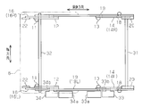
- FIG. 1 is a perspective view showing a vehicle seat to which a seat lifter device according to a first embodiment of the present invention is applied.
- the top view which shows the seat lifter apparatus of FIG.
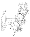
- the disassembled perspective view which shows the seat lifter apparatus of FIG.
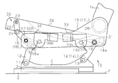
- movement of the seat lifter apparatus of FIG. The side view which shows operation
- FIG. 1 is a perspective view showing a seat 1 which is a front seat of a vehicle such as an automobile.
- a pair of lower rails 2 facing the width direction of the seat 1 and extending in the front-rear direction are fixed to the vehicle floor F (see FIG. 4).
- An upper rail 3 is attached to each lower rail 2 so as to be movable relative to the lower rail 2.
- the pair of lower rails 2 and the pair of upper rails 3 constitute a slide mechanism.
- Each upper rail 3 is coupled with a flat bracket 4 (sheet support member) extending upward. More specifically, as shown in a cross-sectional view in a circle C in FIG. 1, the upper rail 3 includes a pair of opposing members 3a formed by bending a plate material. The pair of members 3a are symmetrical to each other. Each bracket 4 is fastened to a vertical wall portion formed in the center portion of the corresponding upper rail 3 with, for example, a bolt / nut or a caulking pin. A sheet main body 5 is fixed and supported by both the brackets 4 via a lifter mechanism 10.
- the seat body 5 includes a seat cushion 6, a seat back 7 that is supported by a rear end portion of the seat cushion 6 so as to be tiltable (rotatable), and a headrest 8 supported by the upper end portion of the seat back 7.
- the front / rear position of the seat body 5 can be adjusted by the slide mechanism, and the up / down position of the seat body 5 can be adjusted by the lifter mechanism 10.
- the seated person of the said seat main body 5 can adjust the up-and-down position of the seat main body 5 according to the physique, for example, in order to obtain a desired viewpoint.
- FIG. 2 and 3 are a plan view and an exploded perspective view showing a skeleton shape of the sheet body 5, respectively.
- one end portion (first end portion) of the front link 12 is rotatably connected to the front portion of each bracket 4 by a support shaft 11.
- One end portion (first end portion) of the rear link 14 is rotatably connected to the rear portion of each bracket 4 by a support shaft 13.
- the front link 12 and the rear link 14 extend rearward with respect to the respective support shafts 11 and 13.
- One end portion (first end portion) of the tilt link 16 is rotatably connected to the other end portion (second end portion) of each front link 12 by a support shaft 15.
- the tilt link 16 extends forward with respect to the support shaft 15.
- the front and rear portions of the lower arm 19 (frame member) are rotated by the support shafts 17 and 18 respectively at the longitudinal intermediate portion of each tilt link 16 and the other end portion (second end portion) of each rear link 14. It is connected freely. Both the lower arms 19 form a skeleton on both sides of the seat cushion 6. A seat back frame 7 a that forms a skeleton on both sides of the seat back 7 is supported via the reclining mechanism 20 at the rear end portions of the lower arms 19.
- Each rear link 14 extends rearward with respect to the support shaft 13 (the connection portion between the bracket 4 and the rear link 14) more than the support shaft 18 (the connection portion between the lower arm 19 and the rear link 14). It has a protruding portion 14a. Both the extending portions 14a are fixed to both end portions of the rear connecting rod 31 as a beam member extending in the sheet width direction. Both support shafts 17 are fixed to both ends of a front connecting rod 32 extending in the sheet width direction.
- each tilt link 16 is rotatably connected to one end portion (first end portion) of the swing link 22 by a support shaft 21.
- the swing link 22 extends upward with respect to the support shaft 21.
- the front end of a cushion pan 24 as a cushion member is rotatably connected to the other end (second end) of each swing link 22 by a support shaft 23.
- the cushion pan 24 is formed in a substantially square dish shape in accordance with the substantially square shape formed by the lower arms 19 and the rear connecting rod 31.
- the rear part of the cushion pan 24 is rotatably connected to the rear connecting rod 31.
- the cushion pan 24 forms the skeleton of the seat cushion 6 and holds a cushion material for sitting.
- the left rear link 14 (hereinafter referred to as the rear link 14L) toward the front of the seat includes a substantially sector-shaped sector gear portion 14b that extends toward the front about the support shaft 18.
- a lifter drive device 33 as a rotation transmission member is fixed to the outer surface of the left lower arm 19 (hereinafter referred to as the lower arm 19L) toward the front of the seat.
- the lifter drive device 33 includes an electric motor 33a and a pinion 33b that is rotationally driven by the electric motor 33a via an appropriate speed reduction mechanism.
- the pinion 33b penetrates the lower arm 19L and meshes with the sector gear portion 14b.
- the motion of the rear link 14L is transmitted to the right rear link 14 (hereinafter referred to as the rear link 14R) toward the front of the seat via the rear connecting rod 31.
- the left and right rear links 14L and 14R centering on the support shaft 13 rotate in conjunction with each other.
- the lifter driving device 33 and the like form the lifter mechanism 10.
- the left tilt link 16 (hereinafter referred to as tilt link 16L) toward the front of the seat includes a substantially sector-shaped sector gear portion 16a that extends from the support shaft 17 toward the rear.
- a front tilt drive device 34 is fixed to the outer surface of the lower arm 19L in front of the lifter drive device 33.
- the front tilt drive device 34 includes an electric motor 34a and a pinion 34b that is rotationally driven by the electric motor 34a via an appropriate speed reduction mechanism.
- the pinion 34b penetrates the lower arm 19L and meshes with the sector gear portion 16a.
- the tilt link 16L meshing with the pinion 34b in the sector gear portion 16a tries to rotate around the support shaft 17.
- the support shaft 17 moves up and down together with the swing link 22 and the front portion of the lower arm 19L as a result.
- the pinion 34b meshing with the sector gear portion 16a is locked by the speed reduction mechanism, thereby the lower arm 19L supporting the pinion 34b (front tilt drive device 34) and
- the tilt link 16L is substantially integrated.
- tilt link 16R the right tilt link 16
- the front tilt drive device 34 and the like form a tilt mechanism 30.
- the operation of the lifter mechanism 10 will be described on the assumption that the drive of the front tilt drive unit 34 is stopped and the tilt link 16 and the swing link 22 are substantially integrated with the lower arm 19 that supports the front tilt drive unit 34.
- the bracket 4 (upper rail 3), the front link 12, the rear link 14, and the lower arm 19 form a four-node rotating chain with the lower arm 19 as a mediating node (joint node).
- the bracket 4 (upper rail 3), the front link 12, the rear link 14, and the cushion pan 24 form a four-joint rotation chain having the cushion pan 24 as a mediating node.
- the cushion pan 24 also moves substantially upward.
- the rear connecting rod 31 that connects the rear portion of the cushion pan 24 and the rear link 14 is disposed rearward of the support shaft 18 that connects the lower arm 19 and the rear link 14. That is, the distance between the rear connecting rod 31 and the support shaft 13 is larger than the distance between the support shaft 18 and the support shaft 13. Therefore, the cushion pan 24 moves higher than the lower arm 19 by an amount corresponding to the difference between the distances.
- the cushion pan 24 also moves substantially downward.
- the rear part of the cushion pan 24 moves below the lower arm 19 by an amount corresponding to the above-described distance difference.
- the distance between the cushion pan 24 and the reclining mechanism 20 changes through the adjustment of the vertical position of the seat body 5 by the lifter mechanism 10.
- the distance decreases when the vertical position moves upward due to the adjustment by the lifter mechanism 10 and increases when it moves downward.
- the cushion pan 24 (seat cushion 6) is largely moved upward, the amount of upward movement of the lower arm 19 (seat back 7) is suppressed compared to that of the cushion pan 24 (seat cushion 6). It is done.
- the cushion pan 24 (seat cushion 6) is moved largely downward, the downward movement amount of the lower arm 19 (seat back 7) is suppressed as compared with that of the cushion pan 24 (seat cushion 6).
- the amount of up and down movement of the seat back 7 is suppressed. be able to.
- the operation of the tilt mechanism 30 will be described on the assumption that the drive of the lifter drive device 33 is stopped.
- the tilt link 16, the lower arm 19, the swing link 22, and the cushion pan 24 form a four-joint rotation chain with the swing link 22 as a medial node.
- the S-shaped curve of the back and the S-shaped curve of the seat back can be matched.
- the downward movement amount of the seat back 7 is suppressed compared to that of the cushion pan 24 (seat cushion 6), Accordingly, the S-shaped curve of the back and the S-shaped curve of the seat back 7 can be similarly matched.
- the possible adjustment amount of the lower arm 19 in the vertical direction can be reduced as compared with that at the rear part of the cushion pan 24, it is not necessary to lengthen the front link 12 and the rear link 14. Therefore, the strength and rigidity required for the front link 12 and the rear link 14 can be reduced, and the mass of the front link 12 and the rear link 14 can be reduced. Furthermore, a sufficient gap can be ensured between the headrest 8 held at the upper end of the seat back 7 and the ceiling.
- the rear connecting rod 31 is fixed to the rear links 14 so as to bridge between the rear links 14, and the rear portion of the cushion pan 24 (seat cushion 6) is interposed via the rear connecting rod 31. It is connected to both rear links 14. Therefore, the rear part of the cushion pan 24 (seat cushion 6) can be more firmly connected to both rear links 14.
- the cushion pan 24 alone supports the weight of the seated person on the seat. Therefore, the structure of the cushion pan 24 can be greatly simplified.
- the tilt mechanism 30 can tilt the front portion of the cushion pan 24 with the rear portion of the cushion pan 24 as a fulcrum, the seat posture can be adjusted more finely as desired.
- the vertical movement amount of the front portion of the cushion pan 24 is ensured to be larger than that of the lower arm 19, the vertical movement amount of the lower arm 19 (the reclining mechanism 20, the seat back 7) by the lifter mechanism 10 is increased.
- the amount of vertical movement of the front portion of the seat cushion 6 can be increased, and therefore the amount of change in the seating surface angle can be increased.
- the vertical movement amount of the lower arm 19 can be reduced with respect to the vertical movement amount of the rear part of the cushion pan 24. For this reason, even if the rear part of the cushion pan 24 is moved largely upward, the upper and lower gaps between the lower arm 19 and the bracket 4 (seat rail) can be reduced, and thus a protector for preventing the limbs from entering the gap is provided. Can be omitted.
- the rear connecting rod 41 as the beam member of the present embodiment has a pair of shaft portions 41a disposed at both ends, and an axial line shifted in parallel from the axis of both the shaft portions 41a. And having an eccentric portion 41b integrally connecting the shaft portions 41a.
- Each shaft portion 41 a is fixed to the rear end portion of the rear link 42 and is rotatably connected to the rear portion of the lower arm 19.
- the eccentric portion 41b is disposed behind the shaft portion 41a (the connecting portion between the lower arm 19 and the rear link 42) with respect to the support shaft 13 (the connecting portion between the bracket 4 and the rear link 42).
- the structure of the rear link 42 of this embodiment is the same as that of the said 1st Embodiment except the extension part (14a) being omitted.
- the cushion pan 46 forming the front side portion of the cushion member 45 is formed in a substantially square dish shape, and has a pair of attachment pieces 46a extending rearward from both ends in the seat width direction.
- the rear portion of the cushion pan 46 is rotatably connected to a longitudinal intermediate portion (a portion sandwiched between the support shaft 17 and the shaft portion 41a) of the lower arm 19 by a support shaft 48 in each attachment piece 46a.
- the front portion of the cushion pan 46 is rotatably connected to the other end portion (second end portion) of the swing link 22 by the support shafts 23.
- the plurality of S springs 47 forming the rear side portion of the cushion member 45 are juxtaposed in the seat width direction and extend in the front-rear direction while being bent.
- the front end portion of each S spring 47 is locked to a locking portion 46 b disposed at the rear end portion of the cushion pan 46, and the rear end portion of each S spring 47 is connected to the eccentric portion 41 b of the rear connecting rod 41. It is pivotably locked.
- these S springs 47 are eccentric portions behind the shaft portion 41a (the connection portion between the lower arm 19 and the rear link 42) with respect to the support shaft 13 (the connection portion between the bracket 4 and the rear link 42). 41b.
- the operation of the lifter mechanism 10 will be described on the assumption that the drive of the front tilt drive unit 34 is stopped and the tilt link 16 and the swing link 22 are substantially integrated with the lower arm 19 that supports the front tilt drive unit 34.
- the bracket 4 upper rail 3
- the front link 12 the rear link 42
- the lower arm 19 constitute a four-node rotating chain having the lower arm 19 as a mediating node (joint node).
- the cushion member 45 also moves substantially upward.
- the eccentric portion 41 b that connects the rear end portions of the plurality of S springs 47 and the rear link 14 is disposed behind the shaft portion 41 a that connects the lower arm 19 and the rear link 14. That is, the distance between the eccentric portion 41 b and the support shaft 13 is larger than the distance between the shaft portion 41 a and the support shaft 13. Therefore, the cushion member 45 moves higher than the lower arm 19 by an amount corresponding to the difference between the distances.
- the cushion member 45 As the front link 12 and the rear link 42 rotate, the cushion member 45 also moves substantially downward.
- the rear end portions of the plurality of S springs 47 move below the lower arm 19 by an amount corresponding to the above-described distance difference. In other words, even if the cushion member 45 (seat cushion 6) is moved greatly downward, the downward movement amount of the lower arm 19 (seat back 7) is suppressed as compared with that of the cushion member 45 (seat cushion 6). It has been. Note that the displacement of the rear end portion of the S spring 47 with respect to the cushion member 45 at this time is absorbed by the elastic deformation of the S spring 47.
- the tilt link 16, the lower arm 19, the swing link 22, and the cushion pan 46 constitute a four-joint rotation chain having the swing link 22 as a mediating node.
- the tilt link 16 (16L) tries to rotate around the support shaft 17.
- the support shaft 17 moves downward with respect to the support shaft 15 together with the swing link 22.
- the cushion pan 46 rotates about the support shaft 48 in the counterclockwise direction shown in the drawing, and the front portion of the cushion pan 46 (seat cushion 6) moves downward.
- the seat back frame 7a (seat back 7) supported by the rear end portions of the lower arms 19 via the reclining mechanism 20 remains substantially stopped and held at its current position.
- the pivot center (support shaft 48) of the cushion pan 46 is disposed closer to the support shaft 23 than the pivot center (rear side connecting rod 31) of the cushion pan 24 of the first embodiment. For this reason, the front part of the cushion pan 46 (seat cushion 6) can be moved up and down more greatly than the rotation amount of the same tilt link 16 compared to that of the first embodiment.
- the following advantages can be obtained in addition to the advantages (1), (2), (4), and (5) in the first embodiment.
- the rear connecting rod 41 (beam member) serves as a connecting portion (both shaft portions 41a) between the rear link 42 and the lower arm 19, and a connecting portion (eccentric portion 41b) between the rear link 42 and the rear portion of the cushion member 45. ). For this reason, the number of parts can be reduced.
- Such a rear connecting rod 41 can be easily realized by simply bending a conventional rear connecting rod in order to connect a plurality of S springs 47.
- the cushion pan 46 and the plurality of S springs 47 support the weight of the seated person on the seat surface in cooperation. Can do.
- the rear portion of the lower arm 19 and the rear portion of the cushion pan 24 may be connected to the shaft portion 41a and the eccentric portion 41b of the rear side connecting rod 41 in accordance with the second embodiment.
- the rear portion of the lower arm 19 and the rear end portion of the S spring 47 may be connected to the support shaft 18 and the rear connecting rod 31 in accordance with the first embodiment.
- an operation knob as a rotation transmitting member capable of transmitting an operation force for rotating the rear link 14 (14L) may be employed.
- the lower link 19 may be moved up and down by rotating the front link 12 by the lifter drive device 33 (or the above-described operation knob).
- the tilt mechanism 30 may be omitted.
Abstract
シートリフター装置は、シート支持部材と、第1及び第2の端部を備える前リンクであってシート支持部材の前部に第1の端部が回動自在に連結された前リンクと、第1及び第2の端部を備える後リンクであってシート支持部材の後部に第1の端部が回動自在に連結された後リンクと、前リンクの第2の端部に回動自在に連結される前部と、シート支持部材と後リンクとの連結部位よりも後方で後リンクの第2の端部に回動自在に連結される後部とを有するフレーム部材であってシートバックがフレーム部材の後端部に支持されるフレーム部材と、シートクッションの一部を構成するクッション部材であってフレーム部材に回動自在に連結される前部と、後リンクとフレーム部材との連結部位よりもシート支持部材と後リンクとの連結部位から離れた位置で後リンクに回動自在に連結される後部とを有するクッション部材と、前及び後リンクの一方を回動させる回動伝達部材とを備える。
Description
本発明は、シートクッションの上下位置を調整するシートリフター装置に関する。
車両の前部シートなど一部の座席は、例えば、着座者が所望の視点を得るべくその体格に合わせてシートクッションの上下位置を調整することが可能であるシートリフター装置を備えている。従来では、こうした種々のシートリフター装置が提案されている。例えば、特許文献1に記載されたシートリフター装置は、アッパレール上のベース板に取り付けられたリフター機構を備えており、該リフター機構により、シートクッションの上下位置が調整される。前記ベース板にはブラケットが固定されるとともに、該ブラケットにはシートバックがリクライニング機構を介して固定されている。このシートリフター装置では、ベース板及びシートバックに対しシートクッションのみが上下動する。
一方、特許文献2に記載されたシートリフター装置では、シートクッションが、4節回転連鎖を形成する前リンク及び後リンクを介してロアフレームに支持されている。前リンク及び後リンクによりシートクッションの上下位置が調整される。シートクッションには、リクライニング機構を介して、シートバックが固定されている。このシートリフター装置では、特許文献1のそれとは異なり、シートクッション及びシートバックが一体的に上下動する。
一般に、シートバックには、標準的な体格を有する着座者の背中のS字カーブに対応するS字カーブが設けられている。特許文献1のシートリフター装置では、標準的な体格(身長)を有する着座者が、所望の視点を得るべく、シートクッションの上下位置を調整する場合、その着座者の背中のS字カーブはシートバックのそれと、ある程度の範囲で対応することが可能である。しかしながら、小柄な人や大柄な人、すなわち、標準よりも低いまたは高い身長を有する人が、視点の調整のためにシートクッションの上下位置を調整する場合、着座者の背中のS字カーブとシートバックのS字カーブとが大きくずれる可能性がある。
特許文献2のシートリフター装置では、シートクッション及びシートバックは一体的に上下動する。このため、大柄な人や小柄な人については、背中のS字カーブとシートバックのS字カーブとが合わないままの状態になる可能性がある。さらにまた、衝突等でシートバックに加わった荷重は、前リンク及び後リンクによって形成される4節回転連鎖に加わる。このため、前リンク及び後リンクの強度確保のためにその肉厚や幅寸を大きくする必要がある。特に、4節回転連鎖による上下方向へのシートクッションの可能な調整量を大きくするために、これら前リンク及び後リンクを長くする場合には、それらのリンクの強度及び剛性をより一層確保する必要がある。加えて、上下位置の調整によってシートクッションが上方へ移動する場合、それに伴ってシートバックも上方に移動する。このため、該シートバックの上端部に保持されたヘッドレストと天井との間の隙間が小さくなってしまう。
本発明の目的は、着座者の背中のS字カーブとシートバックのS字カーブとのずれを抑制しながらも、着座者の視点の位置を調整することができるシートリフター装置を提供することにある。
上記目的を達成するため、本発明の一態様では、シート支持部材と、第1及び第2の端部を備える前リンクであって、前記シート支持部材の前部に第1の端部が回動自在に連結された前リンクと、第1及び第2の端部を備える後リンクであって、前記シート支持部材の後部に第1の端部が回動自在に連結された後リンクと、前記前リンクの第2の端部に回動自在に連結される前部と、前記シート支持部材と前記後リンクとの連結部位よりも後方において前記後リンクの第2の端部に回動自在に連結される後部とを有するフレーム部材であって、シートバックがフレーム部材の後端部に支持される、フレーム部材と、シートクッションの一部を構成するクッション部材であって、前記フレーム部材に回動自在に連結される前部と、前記後リンクと前記フレーム部材との連結部位よりも前記シート支持部材と前記後リンクとの連結部位から離れた位置で、前記後リンクに回動自在に連結される後部とを有する、クッション部材と、前記前リンク及び前記後リンクのうちの一方を回動させる回動伝達部材とを備えたシートリフター装置を提供する。
(第1の実施形態)
以下、本発明を具体化した第1の実施形態について図面に従って説明する。
以下、本発明を具体化した第1の実施形態について図面に従って説明する。
図1は、例えば自動車などの車両の前部シートであるシート1を示す斜視図である。同図に示すように、車両フロアF(図4参照)には、シート1の幅方向に対向し前後方向に延在する一対のロアレール2が固定されている。各ロアレール2には、該ロアレール2に対し相対移動可能にアッパレール3が装着されている。これら一対のロアレール2及び一対のアッパレール3は、スライド機構を構成する。
各アッパレール3には、上方に延びる平板状のブラケット4(シート支持部材)が結合されている。詳述すると、図1中の円C内に横断面図を示したように、アッパレール3は、板材を曲成してなる対向する一対の部材3aを備える。該一対の部材3aは互いに対称である。各ブラケット4は、対応するアッパレール3の中央部に形成される縦壁部に、例えばボルト・ナット又はかしめピンにて締結されている。これら両ブラケット4には、リフター機構10を介して、シート本体5が固定及び支持されている。このシート本体5は、シートクッション6と、該シートクッション6の後端部に傾動(回動)自在に支持されたシートバック7と、該シートバック7の上端部に支持されたヘッドレスト8とを備える。シート本体5の前後位置は、前記スライド機構により調整可能であるとともに、シート本体5の上下位置は、リフター機構10により調整可能である。これにより、当該シート本体5の着座者は、例えば、所望の視点を得るべく、その体格に合わせてシート本体5の上下位置を調整可能である。
次に、リフター機構10及びその周辺部の構造について更に説明する。
図2及び図3は、それぞれシート本体5の骨格形状を示す平面図及び分解斜視図である。図3に示すように、各ブラケット4の前部には、支持軸11により前リンク12の一方の端部(第1の端部)が回動自在に連結されている。各ブラケット4の後部には、支持軸13により後リンク14の一方の端部(第1の端部)が回動自在に連結されている。前リンク12及び後リンク14は、各々の支持軸11,13に対し後方に延びている。各前リンク12の他方の端部(第2の端部)には、支持軸15によりチルトリンク16の一方の端部(第1の端部)が回動自在に連結されている。チルトリンク16は、支持軸15に対し前方に延びている。
各チルトリンク16の長手方向中間部及び各後リンク14の他方の端部(第2の端部)には、それぞれ支持軸17,18によりロアアーム19(フレーム部材)の前部及び後部がそれぞれ回動自在に連結されている。これら両ロアアーム19は、シートクッション6の両側部の骨格をなす。両ロアアーム19の後端部には、シートバック7の両側部の骨格をなすシートバックフレーム7aがリクライニング機構20を介して支持されている。
なお、各後リンク14は、支持軸13(ブラケット4と後リンク14との間の連結部位)に対し支持軸18(ロアアーム19と後リンク14との間の連結部位)よりも後方に延びる延出部14aを有する。これら両延出部14aは、シート幅方向に延在する梁部材としての後側連結棒31の両端部にそれぞれ固定されている。両支持軸17は、シート幅方向に延在する前側連結棒32の両端部にそれぞれ固定されている。
各チルトリンク16の他方の端部(第2の端部)には、支持軸21により揺動リンク22の一方の端部(第1の端部)が回動自在に連結されている。揺動リンク22は、支持軸21に対し上方に延びている。
各揺動リンク22の他方の端部(第2の端部)には、支持軸23によりクッション部材としてのクッションパン24の前部が回動自在に連結されている。このクッションパン24は、両ロアアーム19及び後側連結棒31のなす略四角形状に合わせて略四角皿状に成形されている。クッションパン24の後部は後側連結棒31に回動自在に連結されている。クッションパン24は、シートクッション6の骨格をなすもので、着座用のクッション材を保持する。
シート前方に向かって左側の後リンク14(以下、後リンク14Lという)は、支持軸18を中心にその前方に向かって広がる略扇状のセクタギヤ部14bを備える。シート前方に向かって左側のロアアーム19(以下、ロアアーム19Lという)の外側面には、回動伝達部材としてのリフター用駆動装置33が固定されている。このリフター用駆動装置33は、電動モータ33aと、該電動モータ33aにより適宜の減速機構を介して回転駆動されるピニオン33bとを有する。ピニオン33bは、ロアアーム19Lを貫通してセクタギヤ部14bと噛合している。
従って、リフター用駆動装置33が駆動されると、セクタギヤ部14bにおいてピニオン33bに噛合する後リンク14Lが支持軸18を中心に回動しようとする。しかしながら、ブラケット4(アッパレール3)は、上下方向に移動できないため、結果として支持軸18はロアアーム19Lの後部とともに支持軸13に対し上下動する。リフター用駆動装置33の駆動が停止されると、セクタギヤ部14bと噛合するピニオン33bが前記減速機構によりロックされ、それによって、該ピニオン33b(リフター用駆動装置33)を支持するロアアーム19L及び後リンク14Lが実質的に一体化される。このとき、後リンク14Lの運動は、後側連結棒31を介してシート前方に向かって右側の後リンク14(以下、後リンク14Rという)に伝達される。これにより、支持軸13を中心とする左右の後リンク14L,14Rは連動して回動する。リフター用駆動装置33等は、リフター機構10を形成する。
シート前方に向かって左側のチルトリンク16(以下、チルトリンク16Lという)は、支持軸17を中心にその後方に向かって広がる略扇状のセクタギヤ部16aを備える。ロアアーム19Lの外側面には、リフター用駆動装置33より前方にフロントチルト用駆動装置34が固定されている。このフロントチルト用駆動装置34は、電動モータ34aと、該電動モータ34aにより適宜の減速機構を介して回転駆動されるピニオン34bとを有する。ピニオン34bは、ロアアーム19Lを貫通してセクタギヤ部16aと噛合している。
従って、フロントチルト用駆動装置34が駆動されると、セクタギヤ部16aにおいてピニオン34bに噛合するチルトリンク16Lが支持軸17を中心に回動しようとする。しかしながら、ブラケット4(アッパレール3)に連結される前リンク12は、上下方向に移動できないため、結果として支持軸15に対し支持軸17が揺動リンク22及びロアアーム19Lの前部とともに上下動する。フロントチルト用駆動装置34の駆動が停止されると、セクタギヤ部16aと噛合するピニオン34bが前記減速機構によりロックされ、それによって、該ピニオン34b(フロントチルト用駆動装置34)を支持するロアアーム19L及びチルトリンク16Lが実質的に一体化される。このとき、チルトリンク16Lの運動は、前側連結棒32を介してシート前方に向かって右側のチルトリンク16(以下、チルトリンク16Rという)に伝達される。これにより、支持軸15を中心とする左右のチルトリンク16L,16Rは連動して回動する。フロントチルト用駆動装置34等は、チルト機構30を形成する。
ここで、本実施形態のシートリフター装置の動作について図4~図6に従って説明する。
まず、フロントチルト用駆動装置34の駆動が停止され、これを支持するロアアーム19にチルトリンク16及び揺動リンク22が実質的に一体化されているものとして、リフター機構10の動作について説明する。このとき、ブラケット4(アッパレール3)、前リンク12、後リンク14及びロアアーム19は、該ロアアーム19を媒介節(連接節)とする4節回転連鎖を形成する。また、ブラケット4(アッパレール3)、前リンク12、後リンク14及びクッションパン24は、該クッションパン24を媒介節とする4節回転連鎖を形成する。
リフター用駆動装置33が駆動され、ピニオン33bが図4において図示時計回転方向に回転すると、支持軸18を中心に回動しようとする後リンク14(14L)がブラケット4(アッパレール3)から押される。これによって、後リンク14が支持軸13を中心に図示反時計回転方向に回動する。これに連動して前リンク12が支持軸11を中心に図示反時計回転方向に回動する。これにより、図5に示すように、それぞれ支持軸11,13よりも後方に配置された支持軸17,18がそれぞれ上方に移動し、ロアアーム19が略上方に移動する。同時に、両ロアアーム19の後端部にリクライニング機構20を介して支持されたシートバックフレーム7a(シートバック7)も上方に移動する。
前リンク12及び後リンク14の回動に伴い、クッションパン24も略上方に移動する。クッションパン24の後部と後リンク14とを連結する後側連結棒31は、ロアアーム19と後リンク14とを連結する支持軸18よりも後方に配置されている。すなわち、後側連結棒31と支持軸13との間の距離は、支持軸18と支持軸13との間の距離より大きい。そのため、クッションパン24は、それらの距離の間の差に応じた分だけロアアーム19よりも大きく上方に移動する。
すなわち、図5に示したように、前リンク12及び後リンク14の回動に伴うクッションパン24の後部、ロアアーム19の移動距離をそれぞれA、Bで表すと、
ロアアームの移動距離B<クッションパンの後部の移動距離A
の関係になっている。
ロアアームの移動距離B<クッションパンの後部の移動距離A
の関係になっている。
一方、リフター用駆動装置33が逆方向に駆動され、ピニオン33bが図5において図示反時計回転方向に回転すると、支持軸18を中心に回動しようとする後リンク14(14L)がブラケット4(アッパレール3)から引かれる。これによって、後リンク14が支持軸13を中心に図示時計回転方向に回動する。これに連動して前リンク12が支持軸11を中心に図示時計回転方向に回動する。これにより、それぞれ支持軸11,13よりも後方に配置された支持軸17,18がそれぞれ下方に移動し、ロアアーム19が略下方に移動する。同時に、シートバックフレーム7a(シートバック7)も下方に移動する。
前リンク12及び後リンク14の回動に伴い、クッションパン24も略下方に移動する。クッションパン24の後部は、前述の距離差に応じた分だけロアアーム19よりも大きく下方に移動する。
リフター機構10によるシート本体5の上下位置の調整を通じて、クッションパン24とリクライニング機構20との間の距離は変化する。その距離は、リフター機構10による調整によって前記上下位置が上方に移動するときに小さくなり、反対に下方に移動するときに大きくなる。換言すれば、クッションパン24(シートクッション6)を上方に大きく移動させたとしても、ロアアーム19(シートバック7)の上方への移動量はクッションパン24(シートクッション6)のそれと比較して抑えられる。クッションパン24(シートクッション6)を下方に大きく移動させたとしても、ロアアーム19(シートバック7)の下方への移動量はクッションパン24(シートクッション6)のそれと比較して抑えられる。
以上により、本実施形態のリフター機構10により、着座者の視点の位置を調整するためにシートクッション6を上下に大きく移動させた場合であっても、シートバック7の上下への移動量を抑えることができる。
次に、リフター用駆動装置33の駆動が停止されているものとして、チルト機構30の動作について説明する。このとき、チルトリンク16、ロアアーム19、揺動リンク22及びクッションパン24は、揺動リンク22を媒介節とする4節回転連鎖を形成する。
フロントチルト用駆動装置34が駆動され、ピニオン34bが図5において図示反時計回転方向に回転すると、チルトリンク16(16L)が支持軸17を中心に回動しようとする。結果として、図6に示すように、支持軸17が揺動リンク22とともに支持軸15に対し上方に移動する。これにより、クッションパン24が後側連結棒31を中心に図示時計回転方向に回動し、該クッションパン24(シートクッション6)の前部が上方に移動する。このとき、両ロアアーム19の後端部にリクライニング機構20を介して支持されたシートバックフレーム7a(シートバック7)は、概ね停止したままであり、その現在の位置に保持される。
一方、フロントチルト用駆動装置34が逆方向に駆動され、ピニオン34bが図6において図示時計回転方向に回転すると、チルトリンク16(16L)が支持軸17を中心に回動しようする。結果として、支持軸17が揺動リンク22とともに支持軸15に対し下方に移動する。これにより、クッションパン24が後側連結棒31を中心に図示反時計回転方向に回動し、該クッションパン24(シートクッション6)の前部が下方に移動する。このとき、両ロアアーム19の後端部にリクライニング機構20を介して支持されたシートバックフレーム7a(シートバック7)は、概ね停止したままであり、その現在の位置に保持される。
以上により、本実施形態のチルト機構30により、シートバック7をほとんど移動させることなく、シートクッション6の前部の上下位置のみを調整することが可能になる。
以上詳述したように、本実施形態によれば、以下に示す利点が得られるようになる。
(1)リフター用駆動装置33による後リンク14の回動に伴って、ロアアーム19の後部がシートバック7と一体で上下動する。ブラケット4、クッションパン24の後部、ロアアーム19の後部は、それぞれ支持軸13、後側連結棒31、支持軸18によって、後リンク14と連結されている。後側連結棒31は、支持軸18より支持軸13から離れており、したがってクッションパン24の後部はロアアーム19の後部よりも大きく上下動する。これにより、例えば小柄な人がクッションパン24(シートクッション6)を上方に大きく移動させたとしても、シートバック7の上方への移動量はクッションパン24(シートクッション6)のそれと比較して抑えられ、それによって、背中のS字カーブとシートバックのS字カーブとを合わせることができる。一方、大柄な人がクッションパン24(シートクッション6)を下方に大きく移動させたとしても、シートバック7の下方への移動量はクッションパン24(シートクッション6)のそれと比較して抑えられ、それによって、同様に背中のS字カーブとシートバック7のS字カーブとを合わせることができる。
また、上下方向へのロアアーム19の可能な調整量をクッションパン24の後部のそれと比較して少なくできるため、前リンク12及び後リンク14を長くする必要がない。したがって、前リンク12及び後リンク14に要求される強度及び剛性を低減することができるとともに、前リンク12及び後リンク14の質量を低減することができる。さらにまた、シートバック7の上端部に保持されたヘッドレスト8と天井との間の隙間を十分に確保することができる。
(2)後側連結棒31は両後リンク14の間を橋渡しするように両後リンク14に固定されており、クッションパン24(シートクッション6)の後部は、後側連結棒31を介して両後リンク14に連結されている。したがって、クッションパン24(シートクッション6)の後部をより堅固に両後リンク14に連結することができる。
(3)座面にかかる着座者の体重を、クッションパン24が単独で支えている。したがって、クッションパン24の構造を極めて簡素化できる。
(4)チルト機構30は、クッションパン24の後部を支点としてクッションパン24の前部を傾動させることができるため、所望の通りにシート姿勢をより細かく調整することができる。特に、クッションパン24の前部の上下の移動量がロアアーム19のそれよりも大きく確保されるため、リフター機構10によるロアアーム19(リクライニング機構20、シートバック7)の上下の移動量を増加させることなく、シートクッション6の前部の上下の移動量を大きくすることができ、したがって、座面角の変化量を大きくすることができる。
(5)クッションパン24の後部の上下の移動量に対し、ロアアーム19の上下の移動量を少なくできる。このため、クッションパン24の後部を上方に大きく移動させても、ロアアーム19及びブラケット4(シートレール)間の上下の隙間を小さくでき、ひいては該隙間への手足の進入を防止するためのプロテクターを割愛することができる。
(第2の実施形態)
以下、本発明を具体化した第2の実施形態について図面に従って説明する。なお、第2の実施形態では、主に、ロアアーム19に連結されるクッション部材の構造が第1の実施形態のそれから変更されている。同様の部分についてはその詳細な説明は省略する。
以下、本発明を具体化した第2の実施形態について図面に従って説明する。なお、第2の実施形態では、主に、ロアアーム19に連結されるクッション部材の構造が第1の実施形態のそれから変更されている。同様の部分についてはその詳細な説明は省略する。
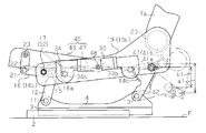
図7及び図8は、それぞれシート本体5の骨格形状を示す分解斜視図及び側面図である。同図に示すように、本実施形態の梁部材としての後側連結棒41は、両端部に配設された一対の軸部41aと、これら両軸部41aの軸線から平行にずれた軸線を有して両軸部41a間を接続する偏心部41bとを一体的に有する。各軸部41aは、それぞれ後リンク42の後方端部に固着されるとともに、前記ロアアーム19の後部に回動自在に連結されている。偏心部41bは、支持軸13(ブラケット4と後リンク42との間の連結部位)に対し軸部41a(ロアアーム19と後リンク42との間の連結部位)よりも後方に配置されている。なお、本実施形態の後リンク42の構造は、延出部(14a)が割愛されていることを除き、前記第1の実施形態のそれと同様である。
また、本実施形態では、クッションパン24に代えて、クッションパン46と、ばね部材としての複数のSばね47とを備える、クッション部材45が用いられる。クッション部材45の前側部を形成するクッションパン46は、略四角皿状に成形されており、そのシート幅方向両端から後方に延びる一対の取付片46aを有する。クッションパン46の後部は、各取付片46aにおいて、ロアアーム19の長手方向中間部(支持軸17と軸部41aとの間に挟まれる部分)に、支持軸48により回動自在に連結されている。クッションパン46の前部は、前記各支持軸23により揺動リンク22の他方の端部(第2の端部)に回動自在に連結されている。
クッション部材45の後側部を形成する複数のSばね47は、シート幅方向に並設されて屈曲しつつ前後方向に延びている。各Sばね47の前端部はクッションパン46の後端部に配設された係止部46bに係止されるとともに、各Sばね47の後端部は後側連結棒41の偏心部41bに回動自在に係止されている。つまり、これらSばね47は、支持軸13(ブラケット4と後リンク42との間の連結部位)に対し軸部41a(ロアアーム19と後リンク42との間の連結部位)よりも後方の偏心部41bに連結されている。
ここで、本実施形態のシートリフター装置の動作について図9を併せ参照して説明する。
まず、フロントチルト用駆動装置34の駆動が停止され、これを支持するロアアーム19にチルトリンク16及び揺動リンク22が実質的に一体化されているものとして、リフター機構10の動作について説明する。このとき、ブラケット4(アッパレール3)、前リンク12、後リンク42及びロアアーム19は、該ロアアーム19を媒介節(連接節)とする4節回転連鎖を構成する。
リフター用駆動装置33が駆動され、ピニオン33bが図8において図示時計回転方向に回転すると、軸部41aを中心に回動しようとする後リンク42がブラケット4(アッパレール3)から押される。これによって、図9に示すように、前述と同様にしてロアアーム19が略上方に移動する。同時に、両ロアアーム19の後端部にリクライニング機構20を介して支持されたシートバックフレーム7a(シートバック7)も上方に移動する。
前リンク12及び後リンク42の回動に伴い、クッション部材45も略上方に移動する。複数のSばね47の後端部と後リンク14とを連結する偏心部41bは、ロアアーム19と後リンク14とを連結する軸部41aよりも後方に配置されている。すなわち、偏心部41bと支持軸13との間の距離は、軸部41aと支持軸13との間の距離より大きい。そのため、クッション部材45は、それらの距離の間の差に応じた分だけロアアーム19よりも大きく上方に移動する。
すなわち、図9に示したように、前リンク12及び後リンク42の回動に伴うSばね47の後端部、ロアアーム19の移動距離をそれぞれA1、B1で表すと、
ロアアームの移動距離B1<Sばねの後端部の移動距離A1
の関係になっている。
ロアアームの移動距離B1<Sばねの後端部の移動距離A1
の関係になっている。
換言すれば、クッション部材45(シートクッション6)を上方に大きく移動させたとしても、ロアアーム19(シートバック7)の上方への移動量はクッション部材45(シートクッション6)のそれと比較して抑えられている。なお、このときのクッション部材45に対するSばね47の後端部の位置ずれは、該Sばね47の弾性変形によって吸収されている。
一方、リフター用駆動装置33が逆方向に駆動され、ピニオン33bが図9において図示反時計回転方向に回転すると、軸部41aを中心に回動しようとする後リンク42がブラケット4(アッパレール3)から引かれる。これによって、前述と同様にしてロアアーム19が略下方に移動する。同時に、シートバックフレーム7a(シートバック7)も下方に移動する。
前リンク12及び後リンク42の回動に伴い、クッション部材45も略下方に移動する。複数のSばね47の後端部は、前述の距離差に応じた分だけロアアーム19よりも大きく下方に移動する。換言すれば、クッション部材45(シートクッション6)を下方に大きく移動させたとしても、ロアアーム19(シートバック7)の下方への移動量はクッション部材45(シートクッション6)のそれと比較して抑えられている。なお、このときのクッション部材45に対するSばね47の後端部の位置ずれは、該Sばね47の弾性変形によって吸収されている。
以上により、着座者の視点の位置を調整するためにシートクッション6を上下に大きく移動させた場合であっても、シートバック7の上下への移動量を抑えることができる。
次に、リフター用駆動装置33の駆動が停止されているものとして、チルト機構30の動作について説明する。このとき、チルトリンク16、ロアアーム19、揺動リンク22及びクッションパン46は、揺動リンク22を媒介節とする4節回転連鎖を構成する。
フロントチルト用駆動装置34が駆動され、ピニオン34bが図9において図示反時計回転方向に回転すると、チルトリンク16(16L)が支持軸17を中心に回動しようとする。結果として、支持軸17が揺動リンク22とともに支持軸15に対し上方に移動する。これにより、クッションパン46が支持軸48を中心に図示時計回転方向に回動し、該クッションパン46(シートクッション6)の前部が上方に移動する。このとき、両ロアアーム19の後端部にリクライニング機構20を介して支持されたシートバックフレーム7a(シートバック7)は、概ね停止したままであり、その現在の位置に保持される。
一方、フロントチルト用駆動装置34が逆方向に駆動され、ピニオン34bが図示時計回転方向に回転すると、チルトリンク16(16L)が支持軸17を中心に回動しようとする。結果として、支持軸17が揺動リンク22とともに支持軸15に対し下方に移動する。これにより、クッションパン46が支持軸48を中心に図示反時計回転方向に回動し、該クッションパン46(シートクッション6)の前部が下方に移動する。このとき、両ロアアーム19の後端部にリクライニング機構20を介して支持されたシートバックフレーム7a(シートバック7)は、概ね停止したままであり、その現在の位置に保持される。
以上により、シートバック7をほとんど移動させることなく、シートクッション6の前部の上下位置のみを調整することが可能になる。特に、クッションパン46の回動中心(支持軸48)は、前記第1の実施形態のクッションパン24の回動中心(後側連結棒31)に比べて支持軸23寄りに配置されている。このため、同じチルトリンク16の回動量に対し第1の実施形態のそれと比べてクッションパン46(シートクッション6)の前部をより大きく上下動させることができる。
以上詳述したように、本実施形態によれば、前記第1の実施形態における(1)(2)(4)(5)の利点に加えて以下に示す利点が得られるようになる。
(6)後側連結棒41(梁部材)は、後リンク42とロアアーム19との連結部位(両軸部41a)として、また後リンク42とクッション部材45の後部との連結部位(偏心部41b)として兼用される。このため、部品点数を削減することができる。係る後側連結棒41は、単に複数のSばね47を連結するために従来からある後側連結棒を曲げ加工することによって、簡単に実現することができる。
(7)クッションパン46及び複数のSばね47からなるクッション部材45を採用したことで、座面にかかる着座者の体重を、これらクッションパン46及び複数のSばね47が協働して支えることができる。
なお、上記実施形態は以下のように変更してもよい。
前記第1の実施形態において、ロアアーム19の後部及びクッションパン24の後部を、前記第2の実施形態に準じて後側連結棒41の軸部41a及び偏心部41bにそれぞれ連結してもよい。
前記第2の実施形態において、ロアアーム19の後部及びSばね47の後端部を、前記第1の実施形態に準じて支持軸18及び後側連結棒31にそれぞれ連結してもよい。
前記各実施形態において、リフター用駆動装置33に代えて、後リンク14(14L)を回動させるための操作力を伝達可能な回動伝達部材としての操作ノブを採用してもよい。
前記各実施形態において、後リンク14(14L)に代えて、リフター用駆動装置33(又は上述の操作ノブ)により前リンク12を回動させて、ロアアーム19等を上下動させてもよい。
前記各実施形態において、チルト機構30を割愛してもよい。
Claims (6)
- シート支持部材と、
第1及び第2の端部を備える前リンクであって、前記シート支持部材の前部に第1の端部が回動自在に連結された前リンクと、
第1及び第2の端部を備える後リンクであって、前記シート支持部材の後部に第1の端部が回動自在に連結された後リンクと、
前記前リンクの第2の端部に回動自在に連結される前部と、前記シート支持部材と前記後リンクとの連結部位よりも後方において前記後リンクの第2の端部に回動自在に連結される後部とを有するフレーム部材であって、シートバックがフレーム部材の後端部に支持される、フレーム部材と、
シートクッションの一部を構成するクッション部材であって、前記フレーム部材に回動自在に連結される前部と、前記後リンクと前記フレーム部材との連結部位よりも前記シート支持部材と前記後リンクとの連結部位から離れた位置で、前記後リンクに回動自在に連結される後部とを有する、クッション部材と、
前記前リンク及び前記後リンクのうちの一方を回動させる回動伝達部材とを備えたシートリフター装置。 - 前記後リンクは、シート幅方向に対向する一対の後リンクであり、
前記シートリフター装置は、梁部材をさらに備え、同梁部材は、前記両後リンクに固着され同後リンクと前記フレーム部材との前記連結部位を提供する一対の軸部と、該両軸部の軸線からずれた軸線を有して前記両軸部間を延びる偏心部とを有し、
前記クッション部材の後部は、前記偏心部を介して前記両後リンクに回動自在に連結されている請求項1に記載のシートリフター装置。 - 前記後リンクは、シート幅方向に対向する一対の後リンクであり、
前記シートリフター装置は、シート幅方向に延在して前記両後リンクに固定される梁部材をさらに備え、同梁部材は、前記クッション部材の後部と前記両後リンクとの一対の連結部位を通る軸線を有し、
前記クッション部材の後部は、前記梁部材を介して前記両後リンクに回動自在に連結されている請求項1に記載のシートリフター装置。 - 前記クッション部材は、
前記フレーム部材に回動自在に連結され、クッション部材の前側部を形成するクッションパンと、
クッション部材の後側部を形成するばね部材であって、前記クッションパンに係止される前端部と、前記梁部材に回動自在に係止される後端部とを有するばね部材とを備えた請求項2又は3に記載のシートリフター装置。 - 前記クッション部材はクッションパンであり、前記クッションパンの後部は前記梁部材に回動自在に連結されている請求項2又は3に記載のシートリフター装置。
- 前記クッション部材の前部を該クッション部材の後部に対し上下動させるチルト機構をさらに備え、前記クッション部材の前部は前記チルト機構を介して前記フレーム部材に連結されている請求項1~5のいずれか一項に記載のシートリフター装置。
Priority Applications (3)
| Application Number | Priority Date | Filing Date | Title |
|---|---|---|---|
| EP20110825212 EP2617601B1 (en) | 2010-09-17 | 2011-09-14 | Seat lifter device |
| US13/819,826 US8616645B2 (en) | 2010-09-17 | 2011-09-14 | Seat lifter device |
| CN2011900007176U CN203221896U (zh) | 2010-09-17 | 2011-09-14 | 座椅升降器装置 |
Applications Claiming Priority (2)
| Application Number | Priority Date | Filing Date | Title |
|---|---|---|---|
| JP2010-209784 | 2010-09-17 | ||
| JP2010209784A JP5218506B2 (ja) | 2010-09-17 | 2010-09-17 | シートリフター装置 |
Publications (1)
| Publication Number | Publication Date |
|---|---|
| WO2012036212A1 true WO2012036212A1 (ja) | 2012-03-22 |
Family
ID=45831668
Family Applications (1)
| Application Number | Title | Priority Date | Filing Date |
|---|---|---|---|
| PCT/JP2011/071019 WO2012036212A1 (ja) | 2010-09-17 | 2011-09-14 | シートリフター装置 |
Country Status (5)
| Country | Link |
|---|---|
| US (1) | US8616645B2 (ja) |
| EP (1) | EP2617601B1 (ja) |
| JP (1) | JP5218506B2 (ja) |
| CN (1) | CN203221896U (ja) |
| WO (1) | WO2012036212A1 (ja) |
Cited By (6)
| Publication number | Priority date | Publication date | Assignee | Title |
|---|---|---|---|---|
| US20170166095A1 (en) * | 2015-12-09 | 2017-06-15 | GM Global Technology Operations LLC | Motor vehicle with height-adjustable seat |
| US20200164772A1 (en) * | 2018-11-26 | 2020-05-28 | Hyundai Motor Company | Height adjustment apparatus of vehicle seat |
| US10759310B2 (en) | 2018-03-22 | 2020-09-01 | Hyundai Motor Company | Vehicle seat and method for controlling sitting position using the same |
| CN113212258A (zh) * | 2021-06-10 | 2021-08-06 | 延锋安道拓座椅有限公司 | 一种座椅五连杆结构 |
| CN114394043A (zh) * | 2022-02-11 | 2022-04-26 | 诺博汽车系统有限公司 | 可调节座椅的骨架和可调节座椅 |
| US11353084B2 (en) * | 2013-03-15 | 2022-06-07 | Clearmotion Acquisition I Llc | Rotary actuator driven vibration isolation |
Families Citing this family (54)
| Publication number | Priority date | Publication date | Assignee | Title |
|---|---|---|---|---|
| CN102781716B (zh) * | 2010-01-21 | 2014-12-24 | 白木工业株式会社 | 阶段式下降装置以及阶段式升降装置 |
| JP5548058B2 (ja) * | 2010-07-12 | 2014-07-16 | 本田技研工業株式会社 | 車両用シートの制御装置 |
| JP5544247B2 (ja) * | 2010-08-20 | 2014-07-09 | 日本発條株式会社 | 車両用シェル型シートのシートクッションシェルユニット及び車両用シェル型シート |
| US9073456B2 (en) * | 2010-10-12 | 2015-07-07 | Ts Tech Co., Ltd. | Vehicle seat |
| DE102011001638A1 (de) * | 2011-03-29 | 2012-10-04 | C. Rob. Hammerstein Gmbh & Co. Kg | Untergestell für einen Kraftfahrzeugsitz |
| JP2012254777A (ja) * | 2011-05-19 | 2012-12-27 | Shiroki Corp | シートリフタ |
| JP5921307B2 (ja) * | 2012-04-18 | 2016-05-24 | 日本発條株式会社 | 車両用シート |
| EP2662238B1 (en) * | 2012-05-08 | 2021-09-29 | Volvo Car Corporation | A seat carrier arrangement |
| WO2014027627A1 (ja) * | 2012-08-14 | 2014-02-20 | 株式会社デルタツーリング | 乗物用シート |
| JP2014113966A (ja) * | 2012-12-12 | 2014-06-26 | Ts Tech Co Ltd | シート装置 |
| US9050914B2 (en) * | 2012-12-31 | 2015-06-09 | Ts Tech Co., Ltd. | Vehicle seat |
| GB2509549B (en) * | 2013-01-08 | 2015-09-16 | Jaguar Land Rover Ltd | Vehicle seat chassis |
| DE102013200812A1 (de) * | 2013-01-18 | 2014-07-24 | Bayerische Motoren Werke Aktiengesellschaft | Kraftfahrzeug |
| CN103264645A (zh) * | 2013-05-31 | 2013-08-28 | 长城汽车股份有限公司 | 座椅调节装置及具有该座椅调节装置的车辆 |
| JP6237468B2 (ja) * | 2013-06-10 | 2017-11-29 | トヨタ紡織株式会社 | 乗物用シート |
| WO2015008713A1 (ja) * | 2013-07-14 | 2015-01-22 | 株式会社デルタツーリング | リフター機構及び乗物用シート |
| US9085246B1 (en) * | 2014-01-17 | 2015-07-21 | GM Global Technology Operations LLC | Vehicle seat stabilization assembly |
| JP6001009B2 (ja) * | 2014-06-10 | 2016-10-05 | トヨタ紡織株式会社 | 乗物用シート |
| US10285883B2 (en) * | 2014-09-18 | 2019-05-14 | Motion Concepts L.P. | Adjustable chair |
| US9586506B2 (en) * | 2014-10-03 | 2017-03-07 | Ford Global Technologies, Llc | Rear seat cushion with H-point articulation |
| WO2016065234A1 (en) * | 2014-10-23 | 2016-04-28 | Gulfstream Aerospace Corporation | Aircraft door with compressible header |
| DE102015201649B4 (de) * | 2014-11-13 | 2017-07-27 | Adient Luxembourg Holding S.à.r.l. | Verbindungselement zur Höhenverstellung eines Fahrzeugsitzes und Fahrzeugsitz |
| JP6524236B2 (ja) * | 2015-07-31 | 2019-06-05 | テイ・エス テック株式会社 | 車両用シート |
| JP6668947B2 (ja) * | 2016-05-26 | 2020-03-18 | トヨタ紡織株式会社 | 乗物用シート |
| CN105882463A (zh) * | 2016-06-18 | 2016-08-24 | 金余和 | 汽车用带扶手安全座椅 |
| CN105882469A (zh) * | 2016-06-18 | 2016-08-24 | 金余和 | 带一环解锁和锁止铰链机构的少儿座椅 |
| CN105882473A (zh) * | 2016-06-18 | 2016-08-24 | 金余和 | 带头枕和发泡缓冲的儿童安全座椅 |
| CN105882472A (zh) * | 2016-06-18 | 2016-08-24 | 金余和 | 带防飞溅和锁止铰链机构的儿童座椅 |
| CN105882471A (zh) * | 2016-06-18 | 2016-08-24 | 金余和 | 带头枕和侧防护的儿童安全座椅 |
| CN105882464A (zh) * | 2016-06-18 | 2016-08-24 | 金余和 | 侧防护缓冲儿童座椅 |
| CN106043041A (zh) * | 2016-06-18 | 2016-10-26 | 金余和 | 汽车用锁止铰链安全座椅 |
| CN105882465A (zh) * | 2016-06-18 | 2016-08-24 | 金余和 | 带脚踏和侧防护的安全座椅 |
| CN106043040A (zh) * | 2016-06-18 | 2016-10-26 | 金余和 | 侧防护型汽车安全座椅 |
| CN105882466A (zh) * | 2016-06-18 | 2016-08-24 | 金余和 | 带安全带组件和发泡缓冲的安全座椅 |
| CN105882470A (zh) * | 2016-06-18 | 2016-08-24 | 金余和 | 多重防护的儿童安全座椅 |
| CN105882468A (zh) * | 2016-06-18 | 2016-08-24 | 金余和 | 汽车用儿童安全座椅 |
| CN105882467A (zh) * | 2016-06-18 | 2016-08-24 | 金余和 | 带锁止铰链机构的儿童安全座椅 |
| DE102016112106B4 (de) * | 2016-07-01 | 2019-07-04 | Grammer Ag | Federungsvorrichtung |
| JP6533247B2 (ja) * | 2017-04-03 | 2019-06-19 | テイ・エス テック株式会社 | 車両用シート |
| US10377281B2 (en) * | 2017-10-25 | 2019-08-13 | GM Global Technology Operations LLC | Seat transformation bracket |
| DE102017126944B4 (de) * | 2017-11-16 | 2019-08-29 | Grammer Aktiengesellschaft | Fahrzeugsitz mit Führungseinrichtung |
| FR3074105B1 (fr) * | 2017-11-29 | 2021-02-26 | Renault Sas | Siege de vehicule au confort ameliore |
| US10569670B2 (en) * | 2018-03-16 | 2020-02-25 | Adient Engineering and IP GmbH | Seat lifter structure and vehicle seat equipped with the same |
| JP7004271B2 (ja) * | 2018-04-10 | 2022-02-04 | 日本発條株式会社 | 車両用シート |
| US10723243B2 (en) | 2018-11-21 | 2020-07-28 | Lear Corporation | Seat adjuster |
| JP7125903B2 (ja) * | 2019-02-20 | 2022-08-25 | シロキ工業株式会社 | 車両用シート昇降装置 |
| US10940776B2 (en) | 2019-04-17 | 2021-03-09 | Ford Global Technologies, Llc | Adjustable seat |
| KR20210047440A (ko) * | 2019-10-22 | 2021-04-30 | 현대자동차주식회사 | 자동차용 시트 제어 시스템 |
| JP7419753B2 (ja) * | 2019-11-08 | 2024-01-23 | トヨタ紡織株式会社 | 乗物用シート |
| US11377000B2 (en) * | 2020-10-05 | 2022-07-05 | Ford Global Technologies, Llc | Support mechanism for seating assembly |
| DE102021107896A1 (de) | 2021-03-29 | 2022-09-29 | Faurecia Autositze Gmbh | Kraftfahrzeugsitz |
| DE102021107897A1 (de) | 2021-03-29 | 2022-09-29 | Faurecia Autositze Gmbh | Kraftfahrzeugsitz |
| DE102022120164A1 (de) | 2022-06-13 | 2023-12-14 | Adient Us Llc | Unterschenkelstützvorrichtung für einen fahrzeugsitz sowie fahrzeugsitz |
| CN115107592B (zh) * | 2022-07-01 | 2023-12-15 | 北京汽车集团越野车有限公司 | 一种座椅的调节结构、座椅和车辆 |
Citations (7)
| Publication number | Priority date | Publication date | Assignee | Title |
|---|---|---|---|---|
| JPS62129013A (ja) | 1985-12-02 | 1987-06-11 | 池田物産株式会社 | 座席 |
| JPH0637152B2 (ja) * | 1986-05-22 | 1994-05-18 | 富士機工株式会社 | シ−トのリフト装置 |
| JPH0732250Y2 (ja) * | 1990-10-22 | 1995-07-26 | 池田物産株式会社 | シートリフター装置 |
| JP2002225600A (ja) | 2001-01-30 | 2002-08-14 | Johnson Controls Automotive Systems Corp | リフター機能付きの車両用シートクッション |
| JP2008024282A (ja) * | 2006-06-22 | 2008-02-07 | Mazda Motor Corp | 車両用シート構造 |
| JP2008049848A (ja) * | 2006-08-24 | 2008-03-06 | Mazda Motor Corp | 自動車用シート装置 |
| JP2009029185A (ja) * | 2007-07-25 | 2009-02-12 | Imasen Electric Ind Co Ltd | 車両用シートの骨組み構造体 |
Family Cites Families (34)
| Publication number | Priority date | Publication date | Assignee | Title |
|---|---|---|---|---|
| KR960004301B1 (ko) | 1986-03-03 | 1996-03-30 | 후지 기꼬오 가부시끼가이샤 | 차량용 시이트 |
| JPH0637152A (ja) | 1992-07-17 | 1994-02-10 | Seiko Epson Corp | 半導体装置の製造方法、および半導体装置 |
| EP0606547B1 (de) * | 1992-11-14 | 1996-12-27 | C. Rob. Hammerstein GmbH | Arretiervorrichtung für eine Längsverstellvorrichtung eines Fahrzeugsitzes |
| JP2915758B2 (ja) | 1993-07-19 | 1999-07-05 | 本田技研工業株式会社 | マフラー用メッキ下地仕上げ方法 |
| JP3532310B2 (ja) * | 1995-07-28 | 2004-05-31 | 株式会社今仙電機製作所 | パワーシートアジャスト装置 |
| DE19646470B4 (de) * | 1996-11-11 | 2005-06-09 | C. Rob. Hammerstein Gmbh & Co. Kg | Kraftfahrzeugsitz mit einer Lehne und einem Sitz |
| DE19754962C1 (de) | 1997-12-11 | 1999-05-12 | Faure Bertrand Sitztech Gmbh | Fahrzeugsitz, insbesondere Kraftfahrzeugsitz |
| CN1138655C (zh) * | 1998-10-13 | 2004-02-18 | 麦格纳座椅系统公司 | 座垫高度调节组件 |
| US6095475A (en) * | 1998-10-23 | 2000-08-01 | Dura Automtive Properties Inc. | Manual height adjustment assembly for a vehicle seat |
| JP2001097083A (ja) * | 1999-09-29 | 2001-04-10 | Aisin Seiki Co Ltd | シートバーチカル装置 |
| FR2801543B1 (fr) * | 1999-11-30 | 2004-10-15 | Aisin Seiki | Appareil vertical pour siege de vehicule |
| US6517157B1 (en) * | 2001-03-16 | 2003-02-11 | Johnson Controls Technology Company | Apparatus for adjusting a seat belt |
| DE10157211A1 (de) * | 2001-11-22 | 2003-06-12 | Keiper Gmbh & Co Kg | Einsteller für einen Fahrzeugsitz |
| JP4069672B2 (ja) * | 2002-05-15 | 2008-04-02 | トヨタ紡織株式会社 | シートバーチカル装置 |
| JP4069688B2 (ja) * | 2002-06-11 | 2008-04-02 | トヨタ紡織株式会社 | シートバーチカル装置 |
| JP4076938B2 (ja) * | 2003-10-07 | 2008-04-16 | 株式会社タチエス | リフタ付きシート構造 |
| JP4501698B2 (ja) | 2004-06-02 | 2010-07-14 | トヨタ紡織株式会社 | 硬度可変式の車両用シート |
| WO2006104288A1 (ja) * | 2005-03-31 | 2006-10-05 | Ts Tech Co., Ltd. | 自動車用シ-トの高さ調整装置 |
| JP4735187B2 (ja) * | 2005-10-24 | 2011-07-27 | アイシン精機株式会社 | 車両用シート調整装置 |
| JP4940654B2 (ja) * | 2005-12-22 | 2012-05-30 | アイシン精機株式会社 | 車両用シート装置 |
| JP5055766B2 (ja) * | 2005-12-27 | 2012-10-24 | アイシン精機株式会社 | 車両用シート装置 |
| DE102006010421A1 (de) * | 2006-03-07 | 2007-09-13 | Recaro Gmbh & Co. Kg | Fahrzeugsitz, insbesondere Kraftfahrzeugsitz |
| US7413252B2 (en) * | 2006-03-20 | 2008-08-19 | Dura Global Technologies, Inc. | Motor vehicle seat lift assembly |
| JP4883441B2 (ja) * | 2006-05-19 | 2012-02-22 | テイ・エス テック株式会社 | 自動車用シートの高さ調整装置 |
| US7604293B2 (en) | 2006-06-09 | 2009-10-20 | Mazda Motor Corporation | Vehicle seat structure |
| US7533936B2 (en) | 2006-08-24 | 2009-05-19 | Mazda Motor Corporation | Vehicle seat assembly |
| US7703851B2 (en) * | 2006-09-21 | 2010-04-27 | Mazda Motor Corporation | Seat device |
| JP2008087554A (ja) * | 2006-09-29 | 2008-04-17 | Aisin Seiki Co Ltd | 車両用シート装置 |
| DE102008006019A1 (de) * | 2007-04-03 | 2008-10-09 | C. Rob. Hammerstein Gmbh & Co. Kg | Kraftfahrzeugsitz mit einem Sitzbereich |
| JP5082789B2 (ja) * | 2007-11-16 | 2012-11-28 | アイシン精機株式会社 | 車両用シート装置 |
| JP5239380B2 (ja) * | 2008-02-18 | 2013-07-17 | トヨタ紡織株式会社 | 車両用シート |
| JP2009202844A (ja) * | 2008-02-29 | 2009-09-10 | Aisin Seiki Co Ltd | シートリフタ装置 |
| US8096617B2 (en) * | 2009-06-16 | 2012-01-17 | Lear Corporation | Seat having tiltable seat cushion |
| JP5026478B2 (ja) * | 2009-07-30 | 2012-09-12 | デルタ工業株式会社 | 車両用シートのリフター装置 |
-
2010
- 2010-09-17 JP JP2010209784A patent/JP5218506B2/ja not_active Expired - Fee Related
-
2011
- 2011-09-14 CN CN2011900007176U patent/CN203221896U/zh not_active Expired - Fee Related
- 2011-09-14 EP EP20110825212 patent/EP2617601B1/en not_active Not-in-force
- 2011-09-14 WO PCT/JP2011/071019 patent/WO2012036212A1/ja active Application Filing
- 2011-09-14 US US13/819,826 patent/US8616645B2/en not_active Expired - Fee Related
Patent Citations (7)
| Publication number | Priority date | Publication date | Assignee | Title |
|---|---|---|---|---|
| JPS62129013A (ja) | 1985-12-02 | 1987-06-11 | 池田物産株式会社 | 座席 |
| JPH0637152B2 (ja) * | 1986-05-22 | 1994-05-18 | 富士機工株式会社 | シ−トのリフト装置 |
| JPH0732250Y2 (ja) * | 1990-10-22 | 1995-07-26 | 池田物産株式会社 | シートリフター装置 |
| JP2002225600A (ja) | 2001-01-30 | 2002-08-14 | Johnson Controls Automotive Systems Corp | リフター機能付きの車両用シートクッション |
| JP2008024282A (ja) * | 2006-06-22 | 2008-02-07 | Mazda Motor Corp | 車両用シート構造 |
| JP2008049848A (ja) * | 2006-08-24 | 2008-03-06 | Mazda Motor Corp | 自動車用シート装置 |
| JP2009029185A (ja) * | 2007-07-25 | 2009-02-12 | Imasen Electric Ind Co Ltd | 車両用シートの骨組み構造体 |
Non-Patent Citations (1)
| Title |
|---|
| See also references of EP2617601A4 |
Cited By (7)
| Publication number | Priority date | Publication date | Assignee | Title |
|---|---|---|---|---|
| US11353084B2 (en) * | 2013-03-15 | 2022-06-07 | Clearmotion Acquisition I Llc | Rotary actuator driven vibration isolation |
| US20170166095A1 (en) * | 2015-12-09 | 2017-06-15 | GM Global Technology Operations LLC | Motor vehicle with height-adjustable seat |
| US10759310B2 (en) | 2018-03-22 | 2020-09-01 | Hyundai Motor Company | Vehicle seat and method for controlling sitting position using the same |
| US20200164772A1 (en) * | 2018-11-26 | 2020-05-28 | Hyundai Motor Company | Height adjustment apparatus of vehicle seat |
| US10744909B2 (en) * | 2018-11-26 | 2020-08-18 | Hyundai Motor Company | Height adjustment apparatus of vehicle seat |
| CN113212258A (zh) * | 2021-06-10 | 2021-08-06 | 延锋安道拓座椅有限公司 | 一种座椅五连杆结构 |
| CN114394043A (zh) * | 2022-02-11 | 2022-04-26 | 诺博汽车系统有限公司 | 可调节座椅的骨架和可调节座椅 |
Also Published As
| Publication number | Publication date |
|---|---|
| JP2012062020A (ja) | 2012-03-29 |
| EP2617601A1 (en) | 2013-07-24 |
| JP5218506B2 (ja) | 2013-06-26 |
| CN203221896U (zh) | 2013-10-02 |
| EP2617601A4 (en) | 2013-10-16 |
| EP2617601B1 (en) | 2015-05-06 |
| US20130161989A1 (en) | 2013-06-27 |
| US8616645B2 (en) | 2013-12-31 |
Similar Documents
| Publication | Publication Date | Title |
|---|---|---|
| WO2012036212A1 (ja) | シートリフター装置 | |
| JP5239380B2 (ja) | 車両用シート | |
| JP7004271B2 (ja) | 車両用シート | |
| JP6324811B2 (ja) | 乗物用シート | |
| JP2012062020A5 (ja) | ||
| KR101738062B1 (ko) | 레그레스트의 구조 | |
| WO2012049871A1 (ja) | 乗物用シート | |
| US9713381B2 (en) | Chair | |
| WO2012049726A1 (ja) | 乗物用シート | |
| JP5690970B2 (ja) | 車両シート | |
| JP2018127082A (ja) | 中折れシートバック | |
| JP2023075318A (ja) | 乗物用シート | |
| US20130284874A1 (en) | Seat underframe for motor vehicle seats | |
| JP4958471B2 (ja) | 車両用シート装置 | |
| US11897371B2 (en) | Seat frame | |
| JP5499739B2 (ja) | 車両用シート | |
| JP2015003573A (ja) | 乗物用シート | |
| JP4019705B2 (ja) | シート装置 | |
| JP6370641B2 (ja) | 乗物用シート | |
| JP2018001815A (ja) | 乗物用シート | |
| US20230398917A1 (en) | Lower leg support device for a vehicle seat, and vehicle seat | |
| JP6870477B2 (ja) | 乗物用シート | |
| JP6701963B2 (ja) | 乗物用シート | |
| JP5750450B2 (ja) | 乗物用シート | |
| WO2018021579A1 (ja) | 乗物用シート |
Legal Events
| Date | Code | Title | Description |
|---|---|---|---|
| WWE | Wipo information: entry into national phase |
Ref document number: 201190000717.6 Country of ref document: CN |
|
| 121 | Ep: the epo has been informed by wipo that ep was designated in this application |
Ref document number: 11825212 Country of ref document: EP Kind code of ref document: A1 |
|
| WWE | Wipo information: entry into national phase |
Ref document number: 13819826 Country of ref document: US |
|
| WWE | Wipo information: entry into national phase |
Ref document number: 2011825212 Country of ref document: EP |
|
| NENP | Non-entry into the national phase |
Ref country code: DE |