WO2012004976A1 - 硬化膜形成方法 - Google Patents
硬化膜形成方法 Download PDFInfo
- Publication number
- WO2012004976A1 WO2012004976A1 PCT/JP2011/003822 JP2011003822W WO2012004976A1 WO 2012004976 A1 WO2012004976 A1 WO 2012004976A1 JP 2011003822 W JP2011003822 W JP 2011003822W WO 2012004976 A1 WO2012004976 A1 WO 2012004976A1
- Authority
- WO
- WIPO (PCT)
- Prior art keywords
- resin composition
- photosensitive resin
- positive photosensitive
- cleaning
- cured film
- Prior art date
- Legal status (The legal status is an assumption and is not a legal conclusion. Google has not performed a legal analysis and makes no representation as to the accuracy of the status listed.)
- Ceased
Links
Images


Classifications
-
- H—ELECTRICITY
- H10—SEMICONDUCTOR DEVICES; ELECTRIC SOLID-STATE DEVICES NOT OTHERWISE PROVIDED FOR
- H10P—GENERIC PROCESSES OR APPARATUS FOR THE MANUFACTURE OR TREATMENT OF DEVICES COVERED BY CLASS H10
- H10P76/00—Manufacture or treatment of masks on semiconductor bodies, e.g. by lithography or photolithography
- H10P76/20—Manufacture or treatment of masks on semiconductor bodies, e.g. by lithography or photolithography of masks comprising organic materials
- H10P76/204—Manufacture or treatment of masks on semiconductor bodies, e.g. by lithography or photolithography of masks comprising organic materials of organic photoresist masks
- H10P76/2041—Photolithographic processes
-
- G—PHYSICS
- G03—PHOTOGRAPHY; CINEMATOGRAPHY; ANALOGOUS TECHNIQUES USING WAVES OTHER THAN OPTICAL WAVES; ELECTROGRAPHY; HOLOGRAPHY
- G03F—PHOTOMECHANICAL PRODUCTION OF TEXTURED OR PATTERNED SURFACES, e.g. FOR PRINTING, FOR PROCESSING OF SEMICONDUCTOR DEVICES; MATERIALS THEREFOR; ORIGINALS THEREFOR; APPARATUS SPECIALLY ADAPTED THEREFOR
- G03F7/00—Photomechanical, e.g. photolithographic, production of textured or patterned surfaces, e.g. printing surfaces; Materials therefor, e.g. comprising photoresists; Apparatus specially adapted therefor
- G03F7/004—Photosensitive materials
- G03F7/022—Quinonediazides
- G03F7/023—Macromolecular quinonediazides; Macromolecular additives, e.g. binders
- G03F7/0233—Macromolecular quinonediazides; Macromolecular additives, e.g. binders characterised by the polymeric binders or the macromolecular additives other than the macromolecular quinonediazides
-
- G—PHYSICS
- G03—PHOTOGRAPHY; CINEMATOGRAPHY; ANALOGOUS TECHNIQUES USING WAVES OTHER THAN OPTICAL WAVES; ELECTROGRAPHY; HOLOGRAPHY
- G03F—PHOTOMECHANICAL PRODUCTION OF TEXTURED OR PATTERNED SURFACES, e.g. FOR PRINTING, FOR PROCESSING OF SEMICONDUCTOR DEVICES; MATERIALS THEREFOR; ORIGINALS THEREFOR; APPARATUS SPECIALLY ADAPTED THEREFOR
- G03F7/00—Photomechanical, e.g. photolithographic, production of textured or patterned surfaces, e.g. printing surfaces; Materials therefor, e.g. comprising photoresists; Apparatus specially adapted therefor
- G03F7/20—Exposure; Apparatus therefor
-
- G—PHYSICS
- G03—PHOTOGRAPHY; CINEMATOGRAPHY; ANALOGOUS TECHNIQUES USING WAVES OTHER THAN OPTICAL WAVES; ELECTROGRAPHY; HOLOGRAPHY
- G03F—PHOTOMECHANICAL PRODUCTION OF TEXTURED OR PATTERNED SURFACES, e.g. FOR PRINTING, FOR PROCESSING OF SEMICONDUCTOR DEVICES; MATERIALS THEREFOR; ORIGINALS THEREFOR; APPARATUS SPECIALLY ADAPTED THEREFOR
- G03F7/00—Photomechanical, e.g. photolithographic, production of textured or patterned surfaces, e.g. printing surfaces; Materials therefor, e.g. comprising photoresists; Apparatus specially adapted therefor
- G03F7/26—Processing photosensitive materials; Apparatus therefor
- G03F7/30—Imagewise removal using liquid means
- G03F7/3042—Imagewise removal using liquid means from printing plates transported horizontally through the processing stations
- G03F7/3071—Process control means, e.g. for replenishing
-
- G—PHYSICS
- G03—PHOTOGRAPHY; CINEMATOGRAPHY; ANALOGOUS TECHNIQUES USING WAVES OTHER THAN OPTICAL WAVES; ELECTROGRAPHY; HOLOGRAPHY
- G03F—PHOTOMECHANICAL PRODUCTION OF TEXTURED OR PATTERNED SURFACES, e.g. FOR PRINTING, FOR PROCESSING OF SEMICONDUCTOR DEVICES; MATERIALS THEREFOR; ORIGINALS THEREFOR; APPARATUS SPECIALLY ADAPTED THEREFOR
- G03F7/00—Photomechanical, e.g. photolithographic, production of textured or patterned surfaces, e.g. printing surfaces; Materials therefor, e.g. comprising photoresists; Apparatus specially adapted therefor
- G03F7/26—Processing photosensitive materials; Apparatus therefor
- G03F7/40—Treatment after imagewise removal, e.g. baking
-
- G—PHYSICS
- G03—PHOTOGRAPHY; CINEMATOGRAPHY; ANALOGOUS TECHNIQUES USING WAVES OTHER THAN OPTICAL WAVES; ELECTROGRAPHY; HOLOGRAPHY
- G03F—PHOTOMECHANICAL PRODUCTION OF TEXTURED OR PATTERNED SURFACES, e.g. FOR PRINTING, FOR PROCESSING OF SEMICONDUCTOR DEVICES; MATERIALS THEREFOR; ORIGINALS THEREFOR; APPARATUS SPECIALLY ADAPTED THEREFOR
- G03F7/00—Photomechanical, e.g. photolithographic, production of textured or patterned surfaces, e.g. printing surfaces; Materials therefor, e.g. comprising photoresists; Apparatus specially adapted therefor
- G03F7/26—Processing photosensitive materials; Apparatus therefor
- G03F7/40—Treatment after imagewise removal, e.g. baking
- G03F7/405—Treatment with inorganic or organometallic reagents after imagewise removal
Definitions
- the present invention relates to a method for forming a cured film.
- polybenzoxazole resins and polyimide resins having excellent heat resistance and excellent electrical characteristics, mechanical characteristics, and the like have been used for surface protective films and interlayer insulating films of semiconductor elements.
- a positive photosensitive resin composition in which a diazoquinone compound of a photosensitive material is combined with these resins is used (for example, patents) Reference 1).
- CSP shift to chip size package
- WLP wafer level package
- the photosensitive resin composition When the photosensitive resin composition is dissolved in the alkaline developer, it is considered that the dissolved photosensitive resin composition is present in a high concentration in the photosensitive resin composition side (wafer side) region of the alkaline developer.
- the cleaning process it was found that when the wafer was rotated at high speed, the upper part (on the opposite side of the wafer) of the alkaline developer was removed by centrifugal force before the cleaning liquid was supplied. .
- an alkaline developer in which the photosensitive resin composition is dissolved at a high concentration remains. Then, when the cleaning solution is supplied, the alkali concentration of the alkali developer is lowered, and the photosensitive resin composition dissolved in the alkali developer is deposited, and this deposit remains attached in the vicinity of the opening. It was thought that.
- a method of forming a cured film of a positive photosensitive resin composition on a support An application step of applying the positive photosensitive resin composition to the support; An exposure step of selectively irradiating actinic radiation to the positive photosensitive resin composition; A development step of developing the exposed portion of the positive photosensitive resin composition with an alkaline developer; A cleaning step of cleaning the developer with a cleaning solution and removing an exposed portion of the positive photosensitive resin composition; Curing the positive photosensitive resin composition to form a cured film,
- the cleaning step includes a first cleaning step of supplying a cleaning liquid while rotating the support at a peripheral speed of 0.53 m / s or less, or in a state where the support is stationary. And a second cleaning step of supplying a cleaning liquid while rotating the support at a peripheral speed faster than that of the first cleaning step.
- the support in the first cleaning step, is rotated at a peripheral speed of 0.53 m / s or less, or the rotation of the support is stopped.
- the rotation speed is slow or the rotation of the support is stopped, so that the state in which a large amount of the liquid remains on the support is maintained, and the precipitate remains in the liquid.
- the second cleaning step it can suppress that deposits remain
- a method of forming a cured film of a positive photosensitive resin composition that can form a desired pattern can be provided.
- the method for forming a cured film of the positive photosensitive resin composition of the present embodiment is as follows: A method of forming a cured film of a positive photosensitive resin composition 2 on a support 1, An application step of applying the positive photosensitive resin composition 2 to the support 1; An exposure step of selectively irradiating the positive photosensitive resin composition 2 with actinic radiation for exposure; A developing step of developing the exposed portion 20 of the positive photosensitive resin composition 2 with an alkaline developer D; A cleaning step of cleaning the alkaline developer D with a cleaning solution and removing the exposed portion 20 of the positive photosensitive resin composition; Curing the positive photosensitive resin composition to form a cured film,
- the cleaning step is a first cleaning step of supplying the cleaning liquid while rotating the support 1 at a peripheral speed of 0.53 m / s or less or in a state where the support is stationary
- a coating process (hereinafter also referred to as a coating process) in which a positive photosensitive resin composition 2 is applied to the support 1 to form a coating film, and actinic radiation is selected for the coating film.
- Exposure process (hereinafter also referred to as an exposure process) for irradiating the coating film, supplying an alkali developer D to the coating film, and applying the alkali developer D onto the coating film.
- a cleaning process for rotating the coating film to clean the coating film hereinafter also referred to as a cleaning process
- a curing process for heating the coating film after the cleaning process to form a cured film
- the coating step is a step of applying a positive photosensitive resin composition 2 to a support 1 (substrate) to produce a coating film.
- the support 1 is, for example, a silicon wafer, a ceramic substrate, an aluminum substrate, or the like.
- the application amount is such that the final film thickness after curing is 0.1 to 30 ⁇ m.
- the coating method include spin coating using a spinner, spray coating using a spray coater, dipping, printing, roll coating, and the like.
- An exposure process is a process of irradiating actinic radiation so that it may become a desired pattern shape to the coating film produced at the coating process.
- the photosensitive diazoquinone compound (B) (described later in detail) in the positive photosensitive resin composition 2 constituting the coating film generates an acid due to a chemical change. Therefore, it is dissolved and removed in the development step (described later).
- actinic radiation ultraviolet rays, visible rays and the like can be used, but those having a wavelength of 200 to 500 nm are preferable.
- a photomask or reticle whose surface such as a quartz glass substrate is shielded with, for example, chrome so as to obtain a desired pattern shape is manufactured, and the photo The coating film is irradiated with actinic radiation through a mask 3 or the like.
- the positional relationship between the photomask 3 or the like and the support 1 coated with the positive photosensitive resin composition 2 or the reduction of the pattern drawn on the photomask 3 or the desired pattern can be selected as appropriate.
- the portion of the coating film that has been irradiated with actinic radiation in the exposure step is dissolved and removed with an alkaline developer D, and a positive photosensitive resin composition is obtained.
- This is performed for the purpose of obtaining a relief pattern consisting of two.
- the developing method include a paddle method, but are not limited thereto. In the developing method by the paddle method, the alkaline developer D is supplied so as to spread uniformly on the exposed coating film, and then the supply of the alkaline developer is stopped, and the alkaline developer is deposited on the coating film.
- a step in which the exposed portion 20 of the coating film is dissolved and removed in a state where the coating film is covered with a film of the alkaline developer D is called a stationary step.
- this step since the unexposed portion is also in contact with the alkali developer D, a part of the coating film surface layer is dissolved (hereinafter also referred to as film reduction).
- film reduction a part of the coating film surface layer is dissolved.
- this development mechanism can be explained as follows.
- the photosensitive diazoquinone compound in the positive photosensitive resin composition 2 generates an acid by chemical change upon exposure, so that the solubility in the alkaline developer D is improved.
- the alkali-soluble resin and the photosensitive diazoquinone compound undergo an azo coupling reaction in the presence of the alkali developer D, and form a layer that is hardly soluble in the alkali developer on the surface of the coating film. Solubility in D decreases. Thus, since there is a difference in solubility in the alkaline developer D between the exposed portion and the unexposed portion, a relief pattern made of the positive photosensitive resin composition 2 can be produced by development.
- alkali developer examples include inorganic alkalis such as sodium hydroxide, potassium hydroxide, sodium carbonate, sodium silicate, sodium metasilicate, and aqueous ammonia, primary amines such as ethylamine and n-propylamine, diethylamine, and diamine.
- inorganic alkalis such as sodium hydroxide, potassium hydroxide, sodium carbonate, sodium silicate, sodium metasilicate, and aqueous ammonia
- primary amines such as ethylamine and n-propylamine, diethylamine, and diamine.
- aqueous solution of an alkali such as a quaternary ammonium salt and an aqueous solution in which an appropriate amount of a water-soluble organic solvent such as methanol or ethanol or a surfactant is added thereto can be suitably used.
- the viscosity of the alkali developer at 25 ° C. is 0.8 mPa.s. s or more, 3.0 mPa.s. s or less.
- the development step of the alkaline developer can be performed once by supplying the developer (stationary treatment once), but may be repeated a plurality of times for the purpose of shortening the development time.
- the development time refers to the total time during which the alkali developer is allowed to stand on the coating film.
- the static treatment is performed once, the alkali-soluble resin of the positive photosensitive resin composition 2 constituting the coating film and the alkali in the alkali developer D act, and the alkali concentration of the alkali developer D gradually decreases. As a result, the developing speed decreases.
- the standing treatment is repeated a plurality of times, the alkali concentration of the alkali developer D can be kept high, so that the development time can be shortened.
- the alkaline developer D on the support 1 is removed by, for example, rotating the support 1 after the first static treatment is completed. Then, the alkali developer D is again supplied onto the coating film, and a new alkali developer D film is formed on the coating film.
- the alkali concentration of the alkali developer D may become too high, and the coating film opening 21 may vary in shape and size.
- the number of repetitions of the static treatment of the alkali developer D is preferably 1 to 5 times, particularly preferably 1 to 4 times.
- the washing step is performed to remove the developer that adheres to the coating film after the development step.
- the cleaning step is a step of supplying the cleaning liquid C (for example, water) to the coating film after the developing step (for example, the central portion of the coating film) and rotating the coating film to clean the coating film. is there.
- the central part of the coating film is the central part of rotation when rotated.
- a plurality of locations for supplying the cleaning liquid C may be provided not only at the central portion of the coating film but also at any location between the central portion of the coating film and the outer peripheral portion.
- the cleaning liquid C is not particularly limited, and for example, distilled water can be used.
- the coating film has a peripheral speed of 1 m.
- the cleaning liquid is supplied while rotating at a speed of at least / s, and a residue may be observed in the opening 21.
- the substrate is cleaned while being rotated at 1000 rpm or more.
- the diameter of the substrate it is considered that the silicon wafer as the substrate is a minimum of 4 inches and a maximum of 12 inches.
- the peripheral speed is 5.2 m / s or more in the case of 4 inches and in the case of 12 inches. It is thought that it is 15.7 m / s or more.
- the peripheral speed is the speed at the maximum radius position of the rotating object (here, the coating film). If the rotational speed is n and the maximum radius is R, the peripheral speed is 2 ⁇ nR.
- the mechanism by which the residue is observed in the opening 21 is considered as follows.
- a positive photosensitive resin composition containing an alkali-soluble resin and a photosensitive diazoquinone compound when used, the coating film in the unexposed area is formed with an alkali-soluble resin in the presence of the alkali developer D. Since the photosensitive diazoquinone compound causes an azo coupling reaction, a layer that is hardly soluble in the alkali developer D is formed on the surface of the coating film, while the coating film in the unexposed area is gradually but slightly exposed to the alkali developer. Dissolve.
- the coating film When the coating film is dissolved in the alkaline developer D, the coating film is not uniformly dissolved in the alkaline developer D, but mostly remains at the coating film interface and its periphery.
- the cleaning step is performed in this state, most of the alkaline developer D is rapidly removed from the coating film by rotating the coating film at a peripheral speed of 1 m / s or more.
- the alkaline developer D at and around the coating film interface is difficult to eliminate and remains on the coating film.
- most of the dissolved coating film is dissolved in the alkali developer D.
- the cleaning liquid C is supplied onto the coating film in this state, the alkali concentration of the alkali developer D increases.
- the positive photosensitive resin composition dissolved in the alkaline developer D is deposited, and in particular, a residue is observed in the opening 21 having a large amount dissolved. Further, even when the cleaning liquid is supplied simultaneously with the rotation of the coating film, the alkali developer D at the substantially outer periphery of the coating film is considered to be removed before the cleaning liquid is supplied due to centrifugal force. In this state, as described above, it is considered that the positive photosensitive resin composition is deposited, and in particular, a residue is observed in the opening 21 having a large amount dissolved. In addition, it is estimated that a residue is what the coating film of the unexposed part melt
- the cleaning process applied the support 1 on which the positive photosensitive resin composition 2 was applied, exposed and developed to a peripheral speed of 0.53 m / m. a first cleaning step in which the cleaning liquid C is supplied while rotating at s or less, or in a state where the rotation is stopped, and a first cleaning step in which the cleaning liquid C is supplied while rotating at a faster peripheral speed than in the first cleaning step. It has been found that the generation of residue can be suppressed by including the second washing step.
- the alkaline developer on the coating film is prevented from being abruptly removed from the coating film by rotating at a peripheral speed of 0.53 m / s or less or stopping the rotation. To do.
- the alkali concentration of the alkali developer D on the support can be gradually lowered, and the positive photosensitive resin composition It is possible to prevent the precipitation and clean up.
- the rotation speed is slow or the rotation is stopped.
- the peripheral speed exceeds 0.53 m / s, before the cleaning liquid C is supplied, the upper part (the side opposite to the support 1) of the alkaline developer D is removed by centrifugal force. End up. In this state, even if the cleaning liquid C is supplied, the precipitate is likely to adhere to the opening 21 of the coating film, and the precipitate remains in the opening 21.
- the rotational speed (circumferential speed) of the support 1 in the first cleaning step is 0.53 m / s or less, and by setting the rotation speed to 0.53 m / s or less, residue is deposited in the opening 21. Can be suppressed. More preferably, it is 0.42 m / s or less, and is 0.001 m / s or more. Moreover, although the residue of an opening part is not observed also at 0 m / s, in order to open the opening part 21 accurately, it is preferable to rotate the support body 1, and 0.21 m / s or more is more preferable. There is no problem even if the peripheral speed is within a range of the above peripheral speed, even if the peripheral speed is constant or fluctuating.
- the time for the first cleaning step is preferably 1 second or more and 15 seconds or less, and particularly preferably 5 seconds or more and 10 seconds or less. By setting it to 1 second or more, it is possible to secure a time for gradually decreasing the alkali concentration of the alkali developer D on the support. On the other hand, by setting the time to 15 seconds or less, the state where the concentration distribution of the alkaline developer is generated on the support is prevented from continuing for a long time, and the dimensional accuracy of the opening 21 in the coating film surface is increased. Can be maintained.
- the flow rate when supplying the cleaning liquid C onto the coating film is preferably 0.5 to 1.5 L / min, particularly preferably 0.7 to 1.3 L / min.
- the flow rate of the cleaning liquid C in the cleaning process may be a constant flow rate or a variable flow rate.
- the second cleaning step may be any rotational speed that is faster than the rotational speed (peripheral speed) of the first cleaning process.
- the second cleaning process is rotated at a peripheral speed of 3 to 40 m / s. It is preferable.
- 3 m / s or more the alkali developing solution D on a coating film and the support body 1 can be reliably excluded from a coating film and a support body.
- 40 m / s or less it is thought that there exists an effect of reducing the turbulent flow which generate
- the developer whose alkali concentration is gradually reduced in the first cleaning step is eliminated.
- the peripheral speed of the support 1 in the second cleaning step is a constant peripheral speed or a variable peripheral speed.
- the flow rate of the cleaning liquid at this time is the same as that in the first cleaning step.
- the second cleaning step is preferably performed after the predetermined peripheral speed is reached, for example, by supplying the cleaning liquid, for example, not less than 5 seconds and not more than 30 seconds. By doing so, the developer can be removed.
- cleaning liquid C and the alkali developing solution D on the support body 1 will be gradually removed by rotation of the support body 1 while moving to a 2nd washing
- the alkali developer D containing the coating film at a high concentration does not remain at the coating film interface as in the conventional case.
- the coating film that has undergone the cleaning step is heated to obtain a final pattern.
- the heating temperature is preferably 160 ° C. to 380 ° C., more preferably 180 ° C. to 350 ° C.
- an inert gas such as nitrogen in the heating device.
- the positive photosensitive resin composition 2 adhering to the back surface, side surface or the vicinity of the outer periphery of the support 1 during or after application of the positive photosensitive resin composition 2 to the support 1 is dissolved with a solvent to contaminate the apparatus. It is also possible to suppress this.
- the solvent examples include N-methyl-2-pyrrolidone, ⁇ -butyrolactone, N, N-dimethylacetamide, dimethyl sulfoxide, diethylene glycol dimethyl ether, diethylene glycol diethyl ether, diethylene glycol dibutyl ether, propylene glycol monomethyl ether, dipropylene glycol monomethyl ether, propylene Glycol monomethyl ether acetate, methyl lactate, ethyl lactate, butyl lactate, methyl-1,3-butylene glycol acetate, 1,3-butylene glycol-3-monomethyl ether, methyl pyruvate, ethyl pyruvate, methyl-3-methoxypro Examples include, but are not limited to, pionates. Moreover, you may use individually or in mixture.
- the coating film may be pre-baked to volatilize the solvent, and the coating film may be dried.
- a heating device such as a hot plate or an oven is used, and the heating temperature is preferably 60 to 140 ° C., more preferably 100 to 130 ° C.
- an inert gas such as nitrogen in the heating device.
- the positive photosensitive resin composition 2 will be described in detail.
- the following is an illustration and the positive photosensitive resin composition 2 is not limited to the following.
- Examples of the positive photosensitive resin composition 2 according to the present invention include those containing an alkali-soluble resin (A) and a photosensitive diazoquinone compound (B).
- alkali-soluble resin (A) examples include acrylic resins such as cresol-type novolac resins, hydroxystyrene resins, methacrylic acid resins, and methacrylic ester resins, cyclic olefin resins containing hydroxyl groups, carboxyl groups, and polyamide resins.
- acrylic resins such as cresol-type novolac resins, hydroxystyrene resins, methacrylic acid resins, and methacrylic ester resins
- cyclic olefin resins containing hydroxyl groups, carboxyl groups examples of the alkali-soluble resin (A) include acrylic resins such as cresol-type novolac resins, hydroxystyrene resins, methacrylic acid resins, and methacrylic ester resins, cyclic olefin resins containing hydroxyl groups, carboxyl groups, and polyamide resins.
- polyamide resins are preferred from the viewpoint of excellent heat resistance and good mechanical properties.
- a resin having an ether group or an ester group a resin having a polybenzoxazole precursor structure, a resin having a polyimide precursor structure, and a resin having a polyamic acid ester structure.
- the polyamide-type resin containing the structure shown by following formula (1) can be mentioned, for example.
- the repeating unit of the structure represented by the following formula (1) is preferably 2 to 1000.
- R 1 is a hydroxyl group, —O—R 3 , an alkyl group, an acyloxy group, or a cycloalkyl group, which may be the same or different.
- R 2 is a hydroxyl group or a carboxyl group.
- —O—R 3 or —COO—R 3 which may be the same or different, m and n are integers of 0 to 8.
- R 3 is an organic group having 1 to 15 carbon atoms. . here, when R 1 is more than one if there is no hydroxyl group as a good .R 1 be the same or different, respectively, R 2 is at least one must be a carboxyl group. Further, the carboxyl as R 2 In the absence of a group, R 1 must be at least one hydroxyl group.
- -O-R 3 as a substituent of the -O-R 3
- Y as a substituent of X
- -COO-R 3 represents a hydroxyl group
- R 3 is an organic group having 1 to 15 carbon atoms. If necessary, the hydroxyl group and the carboxyl group may be protected.
- R 3 examples include formyl group, methyl group, ethyl group, propyl group, isopropyl group, tertiary butyl group, tertiary butoxycarbonyl group, phenyl group, benzyl group, tetrahydrofuranyl group, tetrahydropyranyl group and the like. It is done.
- the polyamide-based resin having the structure represented by the general formula (1) includes, for example, a compound selected from diamine containing X or bis (aminophenol), 2,4-diaminophenol, and dicarboxylic acid or dicarboxylic acid containing Y. It is obtained by reacting with a compound selected from acid dichloride, dicarboxylic acid derivatives and the like.
- dicarboxylic acid an active ester dicarboxylic acid derivative obtained by reacting 1-hydroxy-1,2,3-benzotriazole or the like in advance may be used in order to increase the reaction yield and the like.
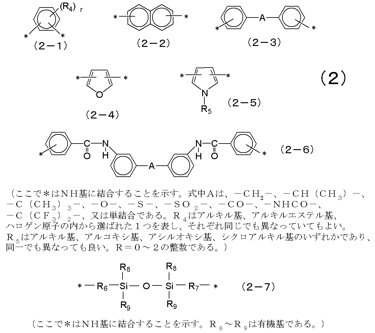
- Examples of X in the general formula (1) include aromatic compounds such as benzene ring and naphthalene ring, heterocyclic compounds such as bisphenols, pyrroles, and furans, and siloxane compounds. What is shown by following formula (2) can be mentioned preferably. These may be used alone or in combination of two or more.
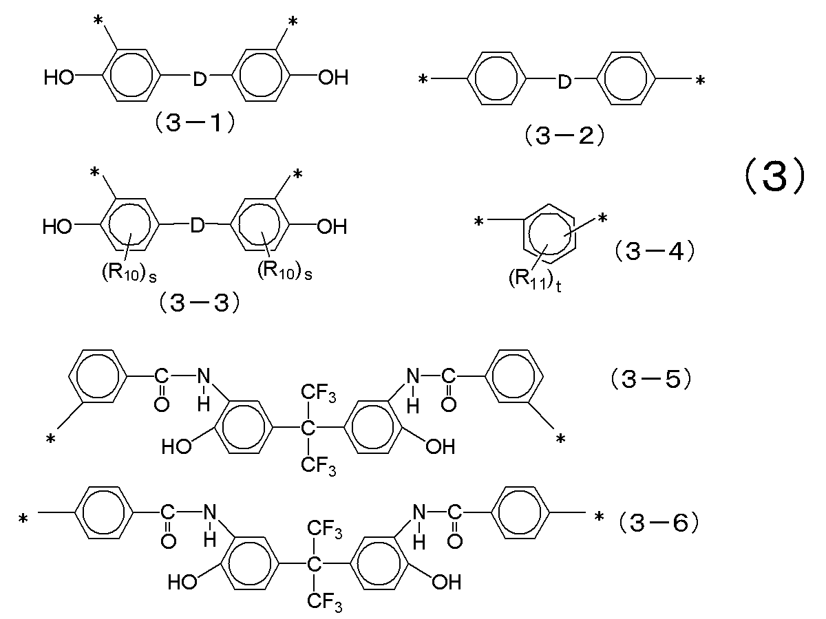
- Particularly preferred among the formulas (2) include those represented by the following formula (3), which are particularly excellent in heat resistance and mechanical properties.
- R 10 is an alkyl group, an alkoxy group, an acyloxy group, or a cycloalkyl group, and is the same
- R 11 represents one selected from an alkyl group, an alkyl ester group, and a halogen atom, and may be the same or different
- s 1 to 3
- t 0 to 2 Is an integer.
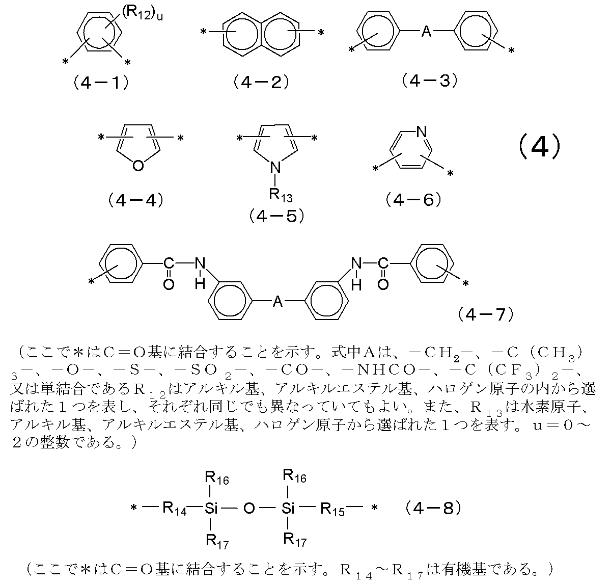
- Y in the general formula (1) is an organic group, and examples thereof include those similar to X.
- aromatic compounds such as benzene ring and naphthalene ring, bisphenols, pyrroles, pyridines, furans, etc.
- the heterocyclic compound of these is mentioned, More specifically, what is shown by following formula (4) can be mentioned preferably. These may be used alone or in combination of two or more.
- R 18 represents one selected from an alkyl group, an alkyl ester group, an alkyl ether group, a benzyl ether group, and a halogen atom
- R 19 represents one selected from a hydrogen atom or an organic group having 1 to 15 carbon atoms, and may be partially substituted
- v is an integer of 0 to 2 is there.
- A is —C (CH 3 ) 3 —, —O—, —SO 2 —, —CO—, or —C (CF 3 ) 2 —.
- the polyamide-based resin represented by the general formula (1) is an acid containing a terminal amino group, an aliphatic group having at least one alkenyl group or alkynyl group, or a cyclic compound group. It is preferred to cap as an amide using an anhydride or acid derivative. Thereby, the preservability of positive photosensitive resin composition can be improved.
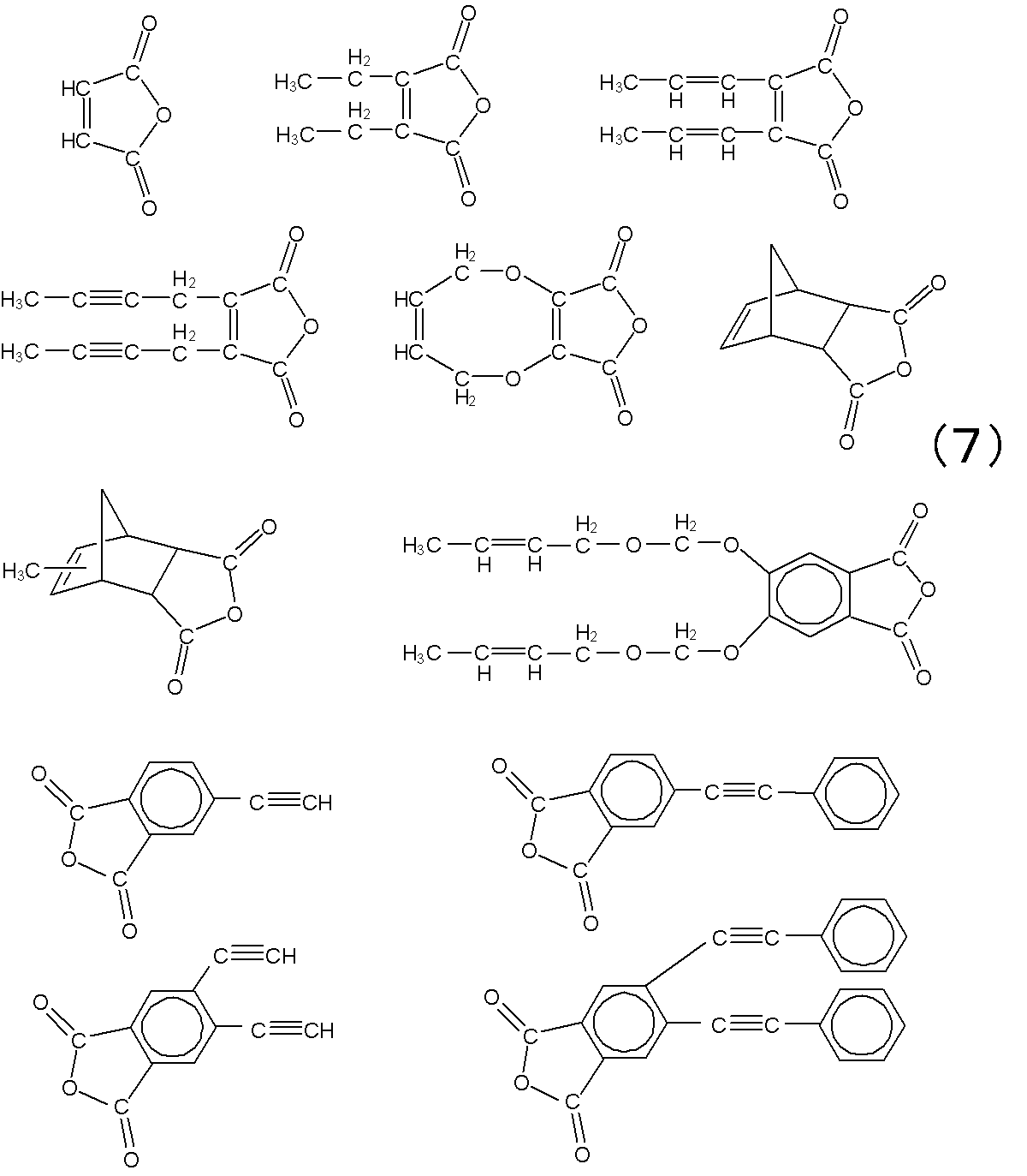
- the acid anhydride containing an aliphatic group or a cyclic compound group having at least one alkenyl group or alkynyl group that reacts with the amino group of the polyamide-based resin include maleic anhydride, bicyclo [2.2.
- An acid derivative containing an aliphatic group or cyclic compound group having at least one alkenyl group or alkynyl group that reacts with an amino group is a carboxylic acid containing an aliphatic group or cyclic compound group having at least one alkenyl group or alkynyl group.
- An acid derivative formed by substituting the OH group of the carboxyl group of an acid or a polyvalent carboxylic acid, such as a halide of carboxylic acid, for example, the following formula (8) is preferred. These may be used alone or in combination of two or more.
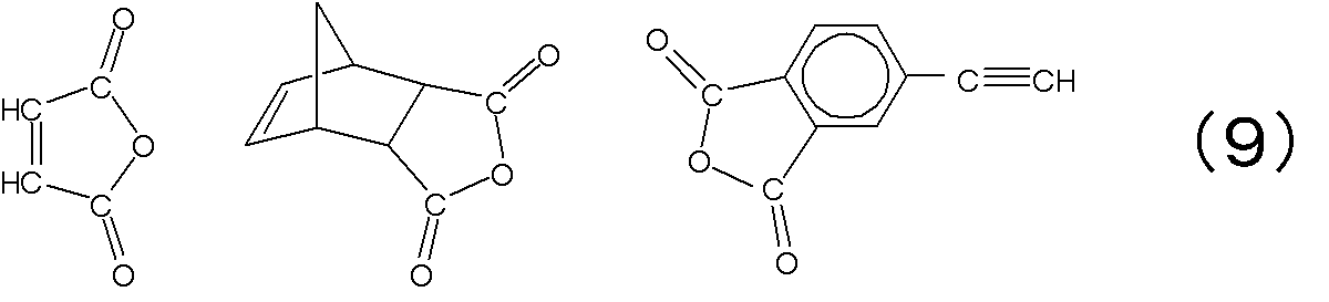
- a group selected by the following formula (9) is preferable as a particularly preferable one. Thereby, preservability can be improved more.
- the method is not limited to the above method, and the terminal acid contained in the polyamide-based resin is reacted with an amine derivative containing an aliphatic group or cyclic compound group having at least one alkenyl group or alkynyl group as an amide. It can also be capped.
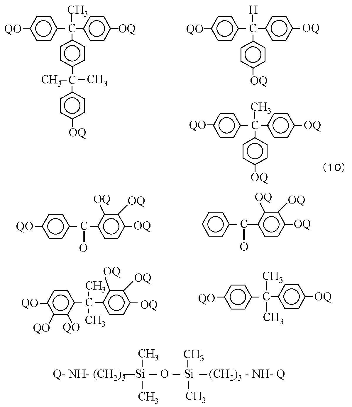
- Examples of the photosensitive diazoquinone compound (B) include esters of a phenol compound and 1,2-naphthoquinone-2-diazide-5-sulfonic acid or 1,2-naphthoquinone-2-diazide-4-sulfonic acid. Specific examples include ester compounds represented by the formulas (10) to (13). These may be used alone or in combination of two or more.
- A represents an organic group
- R 20 to R 23 represent a hydrogen atom or an alkyl group
- R 24 to R 27 represent a hydrogen atom, a hydroxyl group, a halogen atom, an alkyl group, an alkoxy group, an alkenyl group, or a cycloalkyl group. And each of them may be the same or different, and n to q are integers of 0 to 4.
- Q is selected from a hydrogen atom, formula (14), and formula (15).
- at least one of Q of each compound is represented by formula (14) or formula (15).
- the addition amount of the photosensitive diazoquinone compound (B) is preferably 1 to 50 parts by weight with respect to 100 parts by weight of the alkali-soluble resin (A). More preferably, it is 10 to 40 parts by weight. When the addition amount is within the above range, the sensitivity is particularly excellent.
- the positive photosensitive resin composition may contain an additive such as an acrylic, silicone, fluorine, vinyl or the like leveling agent or a silane coupling agent, if necessary.
- silane coupling agent include 3-glycidoxypropyltrimethoxysilane, 3-glycidoxypropylmethyldiethoxysilane, 3-glycidoxypropyltriethoxysilane, p-styryltrimethoxysilane, 3-methacryloxy Propylmethyldimethoxysilane, 3-methacryloxypropyltrimethoxysilane, 3-methacryloxypropylmethyldiethoxysilane, 3-methacryloxypropyltriethoxysilane, 3-acryloxypropyltrimethoxysilane, N-2- (aminoethyl) -3-aminopropylmethyldimethoxysilane, N-2- (aminoethyl) -3-aminopropyltrimethoxysilane, N-2- (
- Solvents include N-methyl-2-pyrrolidone, ⁇ -butyrolactone, N, N-dimethylacetamide, dimethyl sulfoxide, diethylene glycol dimethyl ether, diethylene glycol diethyl ether, diethylene glycol dibutyl ether, propylene glycol monomethyl ether, dipropylene glycol monomethyl ether, propylene glycol Monomethyl ether acetate, methyl lactate, ethyl lactate, butyl lactate, methyl-1,3-butylene glycol acetate, 1,3-butylene glycol-3-monomethyl ether, methyl pyruvate, ethyl pyruvate, methyl-3-methoxypropio And the like, and may be used alone or in combination.
- This application claims priority based on Japanese Patent Application No. 2010-156274 filed on Jul. 9, 2010, the entire disclosure of which
- Example 1 [Synthesis of alkali-soluble resin (A-1)] 443.21 g (0) of a dicarboxylic acid derivative (active ester) obtained by reacting 0.9 mol of diphenyl ether-4,4′-dicarboxylic acid with 1.8 mol of 1-hydroxy-1,2,3-benzotriazole 0.9 mol) and 366.26 g (1 mol) of hexafluoro-2,2-bis (3-amino-4-hydroxyphenyl) propane were equipped with a thermometer, stirrer, raw material inlet, and dry nitrogen gas inlet tube.
- A-1 dicarboxylic acid derivative obtained by reacting 0.9 mol of diphenyl ether-4,4′-dicarboxylic acid with 1.8 mol of 1-hydroxy-1,2,3-benzotriazole 0.9 mol
- 366.26 g (1 mol) of hexafluoro-2,2-bis (3-amino-4-hydroxyphenyl) propane were equipped with a thermometer
- the positive photosensitive resin composition was applied onto a silicon wafer (8 inches) using a spin coater and then pre-baked on a hot plate at 120 ° C. for 4 minutes to obtain a coating film having a thickness of about 8.0 ⁇ m. .
- An i-line stepper (manufactured by Nikon Corporation, NSR Co., Ltd.) is passed through this coating film through a mask (made by Toppan Printing Co., Ltd., test chart No. 1: remaining pattern and blank pattern with a width of 0.88 to 50 ⁇ m are drawn).
- the peripheral speed of the silicon wafer was gradually decreased to finally 0.21 m / s, and at the same time as the developing nozzle was stopped, the rotation of the silicon wafer was stopped and allowed to stand for 50 seconds. At this time, an alkaline developer exists in a film form on the coating film of the silicon wafer. Next, the silicon wafer was rotated at a peripheral speed of 7.33 m / s to remove the developer on the silicon wafer.
- the 2.38% tetramethylammonium hydroxide developer (2.38% tetra The aqueous solution of methylammonium hydroxide) was discharged, the developing nozzle was moved to the vicinity of the outer peripheral portion of the silicon wafer, and the movement of the developing nozzle was stopped in the vicinity of the outer peripheral portion of the silicon wafer.
- the rotational speed of the silicon wafer was gradually decreased to finally 0.21 m / s, and at the same time as the developing nozzle was stopped, the rotation of the wafer was stopped and left for 50 seconds. At this time, an alkaline developer exists in a film form on the coating film of the silicon wafer.
- pure water as a cleaning liquid is supplied to the center of the silicon wafer for 5 seconds (1 L / min, first cleaning step), and then the silicon wafer While rotating the silicon wafer at a peripheral speed of 12.57 m / s, pure water was supplied to the central portion of the silicon wafer for 10 seconds (1 L / min, second cleaning step) and cleaned.
- pure water is supplied simultaneously with the start of rotation of the silicon wafer.
- pure water is supplied until the peripheral speed of the silicon wafer reaches 12.57 m / s after the completion of the first cleaning process. No residue was observed in the coating film opening after washing. The evaluation of the residue was as follows.
- Example 2 the surface condition of the coated film after development and cleaning was evaluated in the same manner as in Example 1 except that the first cleaning step was performed at a peripheral speed of 0.31 m / s for 10 seconds. No residue was observed in the coating film opening after washing.
- Example 3 In Example 1, the surface state of the coated film after development and cleaning was evaluated in the same manner as in Example 1 except that the first cleaning step was performed at a peripheral speed of 0.31 m / s for 1 second. No residue was observed in the coating film opening after washing.
- Example 4 In Example 1, the surface state of the coating film after development and cleaning was evaluated in the same manner as in Example 1 except that the first cleaning step was performed at a peripheral speed of 0.42 m / s for 5 seconds. No residue was observed in the coating film opening after washing.
- Example 5 In Example 1, the surface state of the coated film after development and cleaning was evaluated in the same manner as in Example 1 except that the first cleaning step was performed at a peripheral speed of 0.42 m / s for 10 seconds. No residue was observed in the coating film opening after washing.
- Example 6 In Example 1, the surface condition of the coated film after development and cleaning was evaluated in the same manner as in Example 1 except that the second cleaning step was performed at a peripheral speed of 12.57 m / s for 20 seconds. No residue was observed in the coating film opening after washing.
- Example 7 In Example 1, the surface state of the coating film after development and cleaning was evaluated in the same manner as in Example 1 except that the second cleaning step was performed at a peripheral speed of 3.14 m / s. No residue was observed in the coating film opening after washing.
- Example 8 In Example 1, the surface condition of the coated film after development and cleaning was evaluated in the same manner as in Example 1 except that the second cleaning step was performed at a peripheral speed of 26.18 m / s. No residue was observed in the coating film opening
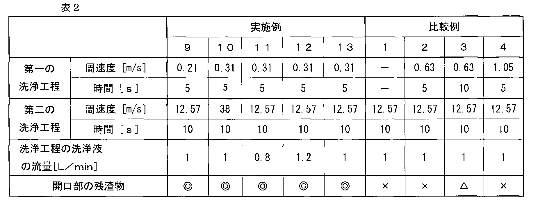
- Example 9 In Example 1, the surface condition of the coated film after development and cleaning was evaluated in the same manner as in Example 1 except that the first cleaning step was performed at a peripheral speed of 0.21 m / s for 5 seconds. No residue was observed in the coating film opening after washing.
- Example 10 In Example 1, the surface condition of the coated film after development and cleaning was evaluated in the same manner as in Example 1 except that the second cleaning step was performed at a peripheral speed of 38 m / s for 10 seconds. No residue was observed in the coating film opening after washing.
- Example 11 In Example 1, the surface condition of the coating film after development and cleaning was evaluated in the same manner as in Example 1 except that the flow rate of the cleaning liquid in the first cleaning process and the second cleaning process was 0.8 L / min. .
- Example 12 In Example 1, the surface state of the coating film after development and cleaning was evaluated in the same manner as in Example 1 except that the flow rate of the cleaning liquid in the first cleaning process and the second cleaning process was 1.2 L / min. . No residue was observed in the coating film opening after the cleaning (evaluation result “ ⁇ ”).
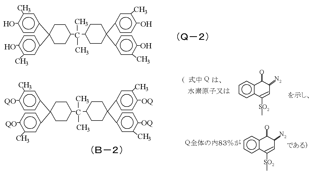
- Example 13 The surface condition of the coated film was evaluated after development and washing in the same manner as in Example 1 except that the photosensitive agent (B-1) in Example 1 was changed to the photosensitive agent (B-2). No residue was observed in the coating film opening after the cleaning (evaluation result “ ⁇ ”).
- the photosensitizer (B-2) was synthesized by mixing 15.82 g (0.025 mol) of phenol formula (Q-2) and 8.40 g (0.083 mol) of triethylamine with a thermometer, stirrer, raw material inlet, Into a four-necked separable flask equipped with a dry nitrogen gas inlet tube, 135 g of tetrahydrofuran was added and dissolved. After cooling the reaction solution to 10 ° C.
- Example 1 the surface state of the coating film after development and cleaning was evaluated in the same manner as in Example 1 except that the first cleaning step was not performed. Residues were observed in the coating film opening after washing (evaluation result “ ⁇ ”).
- Example 2 the surface state of the coated film after development and cleaning was evaluated in the same manner as in Example 1 except that the first cleaning step was performed at a peripheral speed of 0.63 m / s for 5 seconds. Residues were observed in the coating film opening after washing (evaluation result “ ⁇ ”).
- Example 3 In Example 1, the surface condition of the coated film after development and cleaning was evaluated in the same manner as in Example 1 except that the first cleaning step was performed at a peripheral speed of 0.63 m / s for 10 seconds. Residue was observed in the coating film opening after the cleaning (evaluation result “ ⁇ ”). ⁇ Comparative Example 4 >> In Example 1, the surface condition of the coated film after development and cleaning was evaluated in the same manner as in Example 1 except that the first cleaning step was performed at a peripheral speed of 1.05 m / s for 5 seconds. Residues were observed in the coating film opening after washing (evaluation result “ ⁇ ”).
- a method for forming a cured film of a positive photosensitive resin composition capable of forming a pattern at high resolution without a residue in the opening by the method for forming a cured film comprising the positive photosensitive resin composition of the present invention Can be provided.
Landscapes
- Physics & Mathematics (AREA)
- General Physics & Mathematics (AREA)
- Spectroscopy & Molecular Physics (AREA)
- Chemical & Material Sciences (AREA)
- Inorganic Chemistry (AREA)
- Organic Chemistry (AREA)
- Engineering & Computer Science (AREA)
- Automation & Control Theory (AREA)
- Materials For Photolithography (AREA)
- Photosensitive Polymer And Photoresist Processing (AREA)
- Internal Circuitry In Semiconductor Integrated Circuit Devices (AREA)
- Formation Of Insulating Films (AREA)
- Exposure Of Semiconductors, Excluding Electron Or Ion Beam Exposure (AREA)
Abstract
Description
ここでポリベンゾオキサゾール樹脂やポリイミド樹脂を用いた場合のプロセスを簡略化するために、感光材のジアゾキノン化合物をこれらの樹脂と組み合わせたポジ型感光性樹脂組成物が使用されている(例えば、特許文献1参照)。
近年、半導体素子の小型化、高集積化による多層配線化、チップサイズパッケージ(CSP)、ウェハレベルパッケージ(WLP)への移行などにより、半導体素子に対するダメージを低減するため、低応力性に優れたポリベンゾオキサゾール樹脂やポリイミド樹脂を使用したポジ型感光性樹脂組成物が必要とされている。これらポジ型感光性樹脂組成物を実際のプロセスに用いた場合、半導体装置の小型化に伴い微細パターンの形成が必要となる。
アルカリ現像液に感光性樹脂組成物が溶解する際において、アルカリ現像液の感光性樹脂組成物側(ウェハ側)の領域には、溶解した感光性樹脂組成物が高濃度で存在すると考えられる。
洗浄工程において、ウェハを高速で回転させると、洗浄液が供給される前に、アルカリ現像液のうち、上部側(ウェハと反対側)の部分が遠心力により除去されてしまっていることがわかった。ウェハ上には、感光性樹脂組成物が高濃度に溶解したアルカリ現像液が残ってしまう。そして、洗浄液が供給されると、アルカリ現像液のアルカリ濃度が低下し、アルカリ現像液に溶解していた感光性樹脂組成物が析出してしまい、この析出物が開口部付近に付着して残ってしまうと考えられた。
本発明によれば、
支持体にポジ型感光性樹脂組成物の硬化膜を形成する方法であって、
前記支持体に前記ポジ型感光性樹脂組成物を塗布する塗布工程と、
前記ポジ型感光性樹脂組成物に対し、化学線を選択的に照射して露光する露光工程と、
前記ポジ型感光性樹脂組成物の露光部をアルカリ現像液にて現像する現像工程と、
前記現像液を洗浄液にて洗浄するとともに、前記ポジ型感光性樹脂組成物の露光部を除去する洗浄工程と、
前記ポジ型感光性樹脂組成物を加熱して、硬化膜を形成する硬化工程とを有し、
前記洗浄工程は、前記支持体を周速度0.53m/s以下で回転させながら、あるいは、前記支持体を静止した状態で、洗浄液を供給する第一の洗浄工程と、
前記第一の洗浄工程よりも早い周速度で前記支持体を回転させながら洗浄液を供給する第二の洗浄工程とを含むポジ型感光性樹脂組成物の硬化膜形成方法が提供される。
また、仮に感光性樹脂組成物が析出したとしても、回転速度が遅いあるいは支持体の回転が停止しているから、液が多量に支持体上に残った状態が維持され、析出物が液中に浮遊した状態となり、第二の洗浄工程で飛散させることができる。これにより、析出物が残存してしまうことが抑制でき、所望のパターンの硬化膜を得ることができる。
本実施形態のポジ型感光性樹脂組成物の硬化膜形成方法は、
支持体1にポジ型感光性樹脂組成物2の硬化膜を形成する方法であって、
前記支持体1に前記ポジ型感光性樹脂組成物2を塗布する塗布工程と、
前記ポジ型感光性樹脂組成物2に対し、化学線を選択的に照射して露光する露光工程と、
前記ポジ型感光性樹脂組成物2の露光部20をアルカリ現像液Dにて現像する現像工程と、
前記アルカリ現像液Dを洗浄液にて洗浄するとともに、前記ポジ型感光性樹脂組成物の露光部20を除去する洗浄工程と、
前記ポジ型感光性樹脂組成物を加熱して、硬化膜を形成する硬化工程とを有し、
前記洗浄工程は、前記支持体1を周速度0.53m/s以下で回転させながらあるいは、前記支持体を静止した状態(周速度0m/s)で、前記洗浄液を供給する第一の洗浄工程と、
前記第一の洗浄工程よりも早い周速度で前記支持体1を回転させながら前記洗浄液を供給する第二の洗浄工程とを含む。
塗布工程は、図1(A)に示すように、ポジ型感光性樹脂組成物2を支持体1(基板)に塗布し塗布膜を作製する工程である。ここで、支持体1とは、例えば、シリコンウェハ、セラミック基板、アルミ基板などである。塗布量は、半導体素子上に塗布する場合、硬化後の最終膜厚が0.1~30μmになるよう塗布する。膜厚を上記範囲とすることにより、半導体素子の保護表面膜としての機能を十分に発揮することができ、微細な加工パターンが可能であり、加工時間も短くできる。
塗布方法としては、スピンナーを用いた回転塗布、スプレーコーターを用いた噴霧塗布、浸漬、印刷、ロールコーティングなどが挙げられる。
化学線としては、紫外線、可視光線などが使用できるが、200~500nmの波長のものが好ましい。
具体的には、所望のパターン形状が得られるように、石英ガラス基板などの表面を例えばクロムなどで遮蔽させたフォトマスク、レチクル(フォトマスク等3とする)と呼ばれるものを作製し、前記フォトマスク等3を通して前記塗布膜に化学線を照射させる。露光装置の照射方法として、前記フォトマスク等3とポジ型感光性樹脂組成物2を塗布した支持体1との位置関係または、前記フォトマスク等3に描かれたパターンと所望のパターンとの縮小比の関係により、密着露光、近接露光、等倍投影露光、縮小投影露光、走査露光などを適宜選択することができる。
前記パドル方式による現像方法では、露光された塗布膜上にアルカリ現像液Dが一様に濡れ拡がるように供給し、その後、アルカリ現像液の供給を停止し、塗布膜上にアルカリ現像液を盛った状態(塗布膜がアルカリ現像液Dの膜により覆われる状態)にしておき塗布膜の露光部20を溶解除去する工程があり、この工程を静置工程と呼ぶ。この時、未露光部もアルカリ現像液Dと接しているため、塗布膜表層の一部が溶解(以下、膜減りとも記載)する。たとえば、アルカリ可溶性樹脂と感光性ジアゾキノン化合物とを含むポジ型感光性樹脂組成物を使用する場合には、この現像のメカニズムは以下のように説明できる。
露光部は、露光によりポジ型感光性樹脂組成物2中の感光性ジアゾキノン化合物が化学変化により酸を発生するため、アルカリ現像液Dに対する溶解性が向上する。
一方、未露光部は、アルカリ現像液D存在下でアルカリ可溶性樹脂と感光性ジアゾキノン化合物がアゾカップリング反応を生じ、塗布膜表層にアルカリ現像液に難溶である層を形成し、アルカリ現像液Dに対する溶解性が低下する。このように、露光部と未露光部とでアルカリ現像液Dに対する溶解性に差異があるため、現像することによりポジ型感光性樹脂組成物2からなるレリーフパターンを作製することができる。
ここで、アルカリ現像液の25℃での粘度は、0.8mPa.s以上、3.0mPa.s以下である。
前記静置処理が1回の場合、塗布膜を構成するポジ型感光性樹脂組成物2のアルカリ可溶性樹脂とアルカリ現像液D中のアルカリが作用し、しだいにアルカリ現像液Dのアルカリ濃度が低下するため、現像速度が低下してくる。
一方、前記静置処理を複数回繰返し行った場合、アルカリ現像液Dのアルカリ濃度を高い状態に保つことができるため、現像時間を短縮することが可能となる。
静置処理を複数回実施する場合には、1回目の静置処理が終了した後、たとえば、支持体1を回転させることで、支持体1上のアルカリ現像液Dを除去する。そして、再度、塗布膜上に、アルカリ現像液Dを供給し、塗布膜上に新たなアルカリ現像液Dの膜を形成すればよい。
また、前記アルカリ現像液Dの静置処理を複数回繰返し行うと、アルカリ現像液Dの消費量が増えるため、生産コストが高くなるという問題も発生する。
前記アルカリ現像液Dの静置処理の繰返し回数は、1~5回が好ましく、1~4回が特に好ましい。上記範囲とすることで、塗布膜開口部21の形状や大きさにばらつきの少ないものが得られ、さらに、生産コストを低減することが可能となる。
洗浄液Cの供給場所は、塗布膜の中心部のみだけではなく、塗布膜中心部と外周部間の任意の場所に複数設けてもよい。前記洗浄液Cとしては、特に限定されるものではないが、例えば蒸留水を用いることができる。
ここで、従来の洗浄工程では、塗布膜上の現像液、現像液と洗浄液の混合液または洗浄液を回転させながら飛散させる必要があるため、洗浄液を供給し始める際は、塗布膜を周速度1m/s以上で回転させながら洗浄液を供給する場合が普通であり、開口部21に残渣物が観察される場合があった。たとえば、特許4678772号では、基板を1000rpm以上で回転させながら洗浄したとある。基板の直径の記載はないが、基板であるシリコンウェハは最小で4インチ、最大で12インチと考えられるから、周速度は、4インチの場合で5.2m/s以上、12インチの場合で15.7m/s以上であると考えられる。
なお、周速度とは、回転している物体(ここでは、塗布膜)の最大半径位置における速さであり、回転数をn、最大半径をRとすると、周速度は、2πnRとなる。
前述の通り、たとえば、アルカリ可溶性樹脂と感光性ジアゾキノン化合物とを含むポジ型感光性樹脂組成物を使用する場合には、未露光部の塗布膜は、アルカリ現像液D存在下でアルカリ可溶性樹脂と感光性ジアゾキノン化合物がアゾカップリング反応を起こすため、塗布膜表層にアルカリ現像液Dに対して難溶である層を形成する一方、アルカリ現像液により徐々にではあるが未露光部の塗布膜は溶解していく。
アルカリ現像液Dに塗布膜が溶解すると、アルカリ現像液D中に均一に溶解するのではなく、大部分は塗布膜界面およびその周辺に留まる。その状態において洗浄工程を行うと、塗布膜を周速度1m/s以上で回転させることで、大部分のアルカリ現像液Dは塗布膜上より急激に排除される。しかし、塗布膜界面およびその周辺のアルカリ現像液Dは排除されにくく、塗布膜上に残っていると考えられる。
前述の通り、そのアルカリ現像液Dには、溶解した塗布膜の大部分が溶存しており、その状態において、塗布膜上に洗浄液Cが供給されると、アルカリ現像液Dのアルカリ濃度が大きく低下することになり、アルカリ現像液Dに溶解していたポジ型感光性樹脂組成物が析出し、特に、溶解した量が多い開口部21に残渣物が観察されると考えられる。
また、塗布膜の回転と同時に洗浄液を供給する場合においても、遠心力の関係上、塗布膜の略外周部にあるアルカリ現像液Dは、洗浄液が供給される前に排除されると考えられるため、その状態においては、前述の通り、ポジ型感光性樹脂組成物が析出し、特に、溶解した量が多い開口部21に残渣物が観察されると考えられる。なお、残渣物は、未露光部の塗布膜が溶解したものであると推測される。
第一の洗浄工程において、周速度0.53m/s以下で回転あるいは、回転を停止した状態とすることで、塗布膜上のアルカリ現像液が塗布膜上から急激に排除されてしまうことを防止する。
この周速度で回転させつつあるいは、回転を停止した状態で洗浄液を供給することで、支持体上のアルカリ現像液Dのアルカリ濃度を徐々に低下することが可能となり、ポジ型感光性樹脂組成物の析出を抑制して、洗浄することが可能となる。また、仮に、洗浄液の供給速度が速く、アルカリ現像液D中のアルカリ濃度が急激に低下して感光性樹脂組成物が析出したとしても、回転速度が遅い、あるいは回転が停止しているから、液が多量に支持体1上に残った状態が維持され、析出物が液中に浮遊した状態となり、後段の第二の洗浄工程で飛散させることができる。これにより、析出物(残渣物)が残存してしまうことが抑制でき、所望のパターンの硬化膜を得ることができる。
一方で、周速度0.53m/sを超えてしまうと、洗浄液Cが供給される前に、アルカリ現像液Dのうち、上部側(支持体1と反対側)の部分が遠心力により除去されてしまう。この状態で、洗浄液Cを供給しても、析出物は塗布膜の開口部21に付着しやすく、開口部21に析出物が残存してしまう。
第一の洗浄工程の支持体1の回転速度(周速度)は、0.53m/s以下であり、0.53m/s以下とすることで、開口部21に残渣物が析出してしまうことを抑制できる。より好ましくは、0.42m/s以下であり、0.001m/s以上である。また、0m/sにおいても、開口部の残渣物は観察されないが、開口部21を精度良く開口させるためには、支持体1を回転させることが好ましく、0.21m/s以上がより好ましい。
上記周速度の範囲であれば、一定の周速度であっても、変動する周速度であっても問題ない。
また、上記第一の洗浄工程の時間は、1秒以上、15秒以下が好ましく、なかでも、5秒以上、10秒以下が特に好ましい。1秒以上とすることで、支持体上のアルカリ現像液Dのアルカリ濃度を徐々に低下させる時間を確保することができる。一方で、15秒以下とすることで、支持体上でアルカリ現像液の濃度分布が発生している状態が長く続いてしまうことが防止され、塗布膜面内にある開口部21の寸法精度を維持することができる。
また、洗浄工程の洗浄液Cの流量は、一定の流量であっても、変動する流量であっても問題ない。
なお、第一の洗浄工程では、支持体1上に洗浄液Cおよびアルカリ現像液Dが多量に存在するが、洗浄液Cを供給している間、洗浄液Cおよびアルカリ現像液Dは、わずかながら支持体1上から除去される。
第二の洗浄工程では、第一の洗浄工程において、徐々にアルカリ濃度を低下させた現像液を排除する。
第二の洗浄工程の支持体1の周速度は、一定の周速度であっても、変動する周速度であっても問題ない。
また、この際の洗浄液の流量は、第一の洗浄工程と同様である。
第一の洗浄工程から、第二の洗浄工程に移る際、第一の洗浄工程で支持体1を回転させている場合には、支持体1の回転を止めず、支持体1の回転速度を速めればよい。
第二の洗浄工程は、所定の周速度に達してから、洗浄液を供給し、たとえば、5秒以上、30秒以下実施することが好ましい。このようにすることで、現像液を除去することができる。
なお、第一の洗浄工程終了後、第二の洗浄工程に移る間の支持体1の回転により、支持体1上の洗浄液Cおよびアルカリ現像液Dが徐々に除去されることとなる。しかしながら、第一の洗浄工程を実施しているため、従来のように、塗布膜界面に塗布膜を高濃度で含むアルカリ現像液Dが残ることはない。
前記溶剤としては、N-メチル-2-ピロリドン、γ-ブチロラクトン、N,N-ジメチルアセトアミド、ジメチルスルホキシド、ジエチレングリコールジメチルエーテル、ジエチレングリコールジエチルエーテル、ジエチレングリコールジブチルエーテル、プロピレングリコールモノメチルエーテル、ジプロピレングリコールモノメチルエーテル、プロピレングリコールモノメチルエーテルアセテート、乳酸メチル、乳酸エチル、乳酸ブチル、メチル-1,3-ブチレングリコールアセテート、1,3-ブチレングリコール-3-モノメチルエーテル、ピルビン酸メチル、ピルビン酸エチル、メチル-3-メトキシプロピオネートなどが挙げられるが、これらに限ったものではない。また、単独でも混合して用いても良い。
前記プリベークの方法としては、ホットプレート、オーブンなどの加熱装置を用い、加熱温度としては、60~140℃が好ましく、より好ましくは100~130℃である。加熱をする際、加熱装置内に窒素などの不活性ガスを流して、塗布膜の酸化を低減させることも可能である。
なお下記は例示であり、ポジ型感光性樹脂組成物2は下記に限定されるものではない。
本発明に係るポジ型感光性樹脂組成物2は、アルカリ可溶樹脂(A)と、感光性ジアゾキノン化合物(B)とを含むものを例示として挙げることができる。
これらの中でも耐熱性に優れ、機械特性が良いという点からポリアミド系樹脂が好ましく、具体的にはポリベンゾオキサゾール構造およびポリイミド構造の少なくとも一方を有し、かつ主鎖または側鎖に水酸基、カルボキシル基、エーテル基またはエステル基を有する樹脂、ポリベンゾオキサゾール前駆体構造を有する樹脂、ポリイミド前駆体構造を有する樹脂、ポリアミド酸エステル構造を有する樹脂の少なくともいずれか1つが挙げられる。
このようなポリアミド系樹脂としては、例えば下記式(1)で示される構造を含むポリアミド系樹脂を挙げることができる。また、下記式(1)で示される構造の繰り返し単位は、2~1000であることが好ましい。

なお、ジカルボン酸の場合には反応収率等を高めるため、1-ヒドロキシ-1,2,3-ベンゾトリアゾールなどを予め反応させた活性エステル型のジカルボン酸誘導体を用いてもよい。

下記式(5)中のテトラカルボン酸二無水物由来の構造については、C=O基に結合する位置が両方メタ位であるもの、両方パラ位であるものを挙げているが、メタ位とパラ位をそれぞれ含む構造でもよい。


式中Aは、-C(CH3)3-、-O-、-SO2-、-CO-、又は-C(CF3)2-である。)

このような、ポリアミド系樹脂のアミノ基と反応するアルケニル基またはアルキニル基を少なくとも1個有する脂肪族基または環式化合物基を含む酸無水物としては、マレイン酸無水物、ビシクロ[2.2.1]ヘプタ-5-エン-2,3-ジカルボン酸無水物、4-エチニルフタル酸無水物、4-(フェニルエチニル)フタル酸無水物、などが挙げられる。例えば下記式(7)などである。アミノ基と反応するアルケニル基またはアルキニル基を少なくとも1個有する脂肪族基または環式化合物基を含む酸誘導体は、アルケニル基またはアルキニル基を少なくとも1個有する脂肪族基または環式化合物基を含むカルボン酸または多価カルボン酸のカルボキシル基のOH基を置換することにより構成された酸誘導体で、カルボン酸のハロゲン化物などがあり、例えば下記式(8)などが好ましい。これらは単独で用いてもよいし、2種類以上組み合わせて用いても良い。

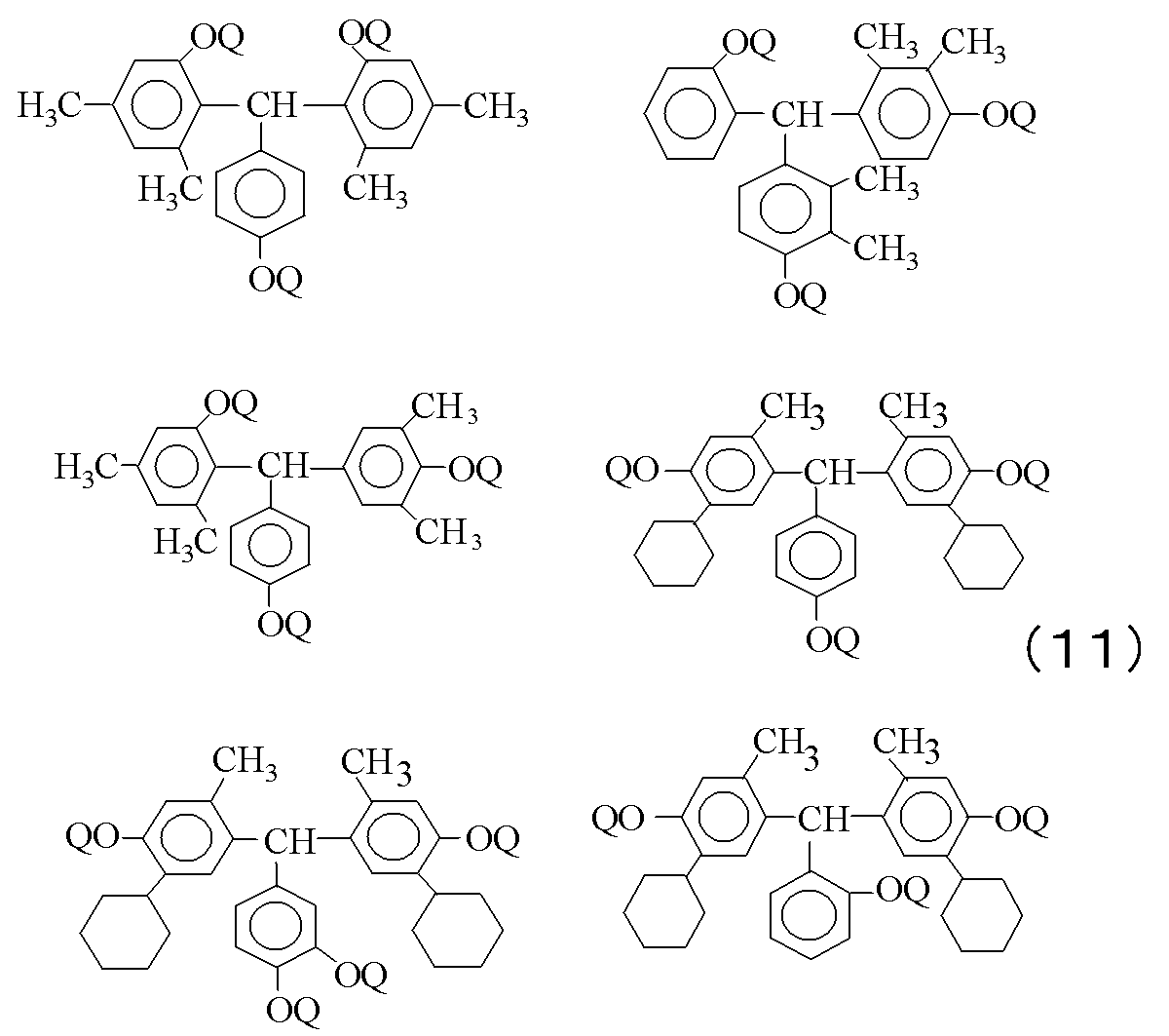


(式中、Aは有機基、R20~R23は水素原子、又はアルキル基、R24~R27は水素原子、水酸基、ハロゲン原子、アルキル基、アルコキシ基、アルケニル基、シクロアルキル基の中から選ばれる1つを表し、それぞれ同じでも異なっていてもよい。n~qは0~4の整数である。)

前記シランカップリング剤としては、3-グリシドキシプロピルトリメトキシシラン、3-グリシドキシプロピルメチルジエトキシシラン、3-グリシドキシプロピルトリエトキシシラン、p-スチリルトリメトキシシラン、3-メタクリロキシプロピルメチルジメトキシシラン、3-メタクリロキシプロピルトリメトキシシラン、3-メタクリロキシプロピルメチルジエトキシシラン、3-メタクリロキシプロピルトリエトキシシラン、3-アクリロキシプロピルトリメトキシシラン、N-2-(アミノエチル)-3-アミノプロピルメチルジメトキシシラン、N-2-(アミノエチル)-3-アミノプロピルトリメトキシシラン、N-2-(アミノエチル)-3-アミノプロピルトリエトキシシラン、3-アミノプロピルトリメトキシシラン、3-アミノプロピルトリエトキシシラン、N-フェニル-3-アミノプロピルトリメトキシシラン、3-メルカプトプロピルメチルジメトキシシラン、3-メルカプトプロピルトリメトキシシラン、ビス(トリエトキシプロピル)テトラスルフィド、3-イソシアネートプロピルトリエトキシシランなどが挙げられるが、これらに限定されない。
この出願は、2010年7月9日に出願された日本特許出願特願2010-156274を基礎とする優先権を主張し、その開示をすべてここに取り込む。
≪実施例1≫
[アルカリ可溶性樹脂(A-1)の合成]
ジフェニルエーテル-4,4'-ジカルボン酸0.9モルと1-ヒドロキシ-1,2,3-ベンゾトリアゾール1.8モルとを反応させて得られたジカルボン酸誘導体(活性エステル)443.21g(0.9モル)とヘキサフルオロ-2,2-ビス(3-アミノ-4-ヒドロキシフェニル)プロパン366.26g(1モル)とを温度計、攪拌機、原料投入口、乾燥窒素ガス導入管を備えた4つ口のセパラブルフラスコに入れ、N-メチル-2-ピロリドン3200gを加えて溶解させた。その後オイルバスを用いて75℃にて12時間反応させた。
次にN-メチル-2-ピロリドン100gに溶解させた4-エチニルフタル酸無水物34.43g(0.2モル)を加え、更に12時間攪拌して反応を終了した。反応混合物を濾過した後、反応混合物を水/イソプロパノール=3/1(体積比)の溶液に投入、沈殿物を濾集し水で充分洗浄した後、真空下で乾燥し、目的のアルカリ可溶性樹脂(A-1)を得た。
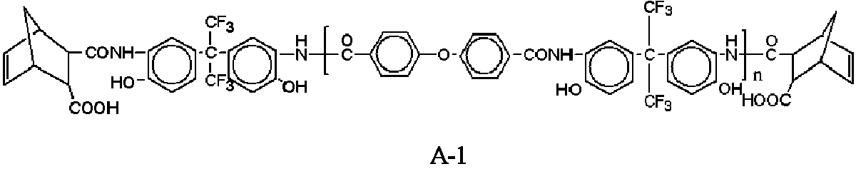
合成したアルカリ可溶性樹脂(A-1)100g、下記式(B-1)の構造を有する感光性ジアゾキノン化合物15gを、γ―ブチロラクトン150gに溶解した後、孔径0.2μmのテフロン(登録商標)製フィルターで濾過しポジ型感光性樹脂組成物を得た。

上記ポジ型感光性樹脂組成物をシリコンウェハ(8インチ)上にスピンコーターを用いて塗布した後、ホットプレートにて120℃で4分プリベークし、膜厚約8.0μmの塗布膜を得た。この塗布膜にマスク(凸版印刷(株)製、テストチャートNo.1:幅0.88~50μmの残しパターン及び抜きパターンが描かれている)を通して、i線ステッパー((株)ニコン製・NSR-4425i)を用いて、100mJ/cm2から780mJ/cm2まで10mJ/cm2刻みで露光量を変化させて化学線を照射した。
次に、ポジ型感光性樹脂組成物が塗布・露光されたシリコンウェハを周速度0.53m/sで回転させて、シリコンウェハの中心部に配置してある現像ノズルから2.38%テトラメチルアンモニウムヒドロキシド現像液(2.38%テトラメチルアンモニウムヒドロキシドの水溶液)を吐出させ、現像ノズルをシリコンウェハの外周部へと移動させ、シリコンウェハの外周部近傍にて現像ノズルの移動を停止させた。現像ノズルを移動させる際にシリコンウェハの周速度を徐々に落としていき最終的には0.21m/sにし、現像ノズルを停止すると同時にシリコンウェハの回転も停止して50秒静置した。このとき、シリコンウェハの塗膜上には、アルカリ現像液が膜状に存在している。
次に、シリコンウェハを周速度7.33m/sで回転させシリコンウェハ上の現像液を排除した。次に、シリコンウェハを周速度7.33m/sで回転させておきながら、シリコンウェハの中心部に配置してある現像ノズルから2.38%テトラメチルアンモニウムヒドロキシド現像液(2.38%テトラメチルアンモニウムヒドロキシドの水溶液)を吐出させ、現像ノズルをシリコンウェハの外周部近傍へと移動させ、シリコンウェハの外周部近傍にて現像ノズルの移動を停止させた。現像ノズルを移動させる際にシリコンウェハの回転数を徐々に落としていき最終的には0.21m/sにし、現像ノズルを停止すると同時に前記ウェハの回転も停止して50秒静置した。このとき、シリコンウェハの塗膜上には、アルカリ現像液が膜状に存在している。
次に、シリコンウェハを周速度0.31m/sで回転させながら、洗浄液である純水をシリコンウェハの中心部に5秒間供給(1L/min、第一の洗浄工程)し、その後、シリコンウェハの回転速度を速めシリコンウェハを周速度12.57m/sで回転させながら、純水をシリコンウェハの中心部に10秒間供給(1L/min、第二の洗浄工程)し、洗浄した。なお、第一の洗浄工程ではシリコンウェハの回転開始と同時に、純水を供給している。また、第一の洗浄工程終了後、シリコンウェハの周速度が12.57m/sに達するまでの間にも、純水は供給されている。
洗浄後の塗布膜開口部に残渣物は観察されなかった。残渣物の評価としては、以下のとおりとした。
◎:塗布膜全体で現像、洗浄後の開口部に残渣物なし。
○:塗布膜の略外周部の一部の開口部に残渣物がごくわずかにあり。
(実用上問題ないレベル)
△:塗布膜の略外周部全体の開口部に残渣物あり。
×:塗布膜全体の開口部に残渣物あり。
実施例1において、第一の洗浄工程を周速度0.31m/sで10秒とした以外は、実施例1と同様に現像、洗浄後塗布膜表面状態の評価を行った。洗浄後の塗布膜開口部に残渣物は観察されなかった。
≪実施例3≫
実施例1において、第一の洗浄工程を周速度0.31m/sで1秒とした以外は、実施例1と同様に現像、洗浄後塗布膜表面状態の評価を行った。洗浄後の塗布膜開口部に残渣物は観察されなかった。
≪実施例4≫
実施例1において、第一の洗浄工程を周速度0.42m/sで5秒とした以外は、実施例1と同様に現像、洗浄後塗布膜表面状態の評価を行った。洗浄後の塗布膜開口部に残渣物は観察されなかった。
実施例1において、第一の洗浄工程を周速度0.42m/sで10秒とした以外は、実施例1と同様に現像、洗浄後塗布膜表面状態の評価を行った。洗浄後の塗布膜開口部に残渣物は観察されなかった。
≪実施例6≫
実施例1において、第二の洗浄工程を周速度12.57m/sで20秒とした以外は、実施例1と同様に現像、洗浄後塗布膜表面状態の評価を行った。洗浄後の塗布膜開口部に残渣物は観察されなかった。
≪実施例7≫
実施例1において、第二の洗浄工程を周速度3.14m/sとした以外は、実施例1と同様に現像、洗浄後塗布膜表面状態の評価を行った。洗浄後の塗布膜開口部に残渣物は観察されなかった。
≪実施例8≫
実施例1において、第二の洗浄工程を周速度26.18m/sとした以外は、実施例1と同様に現像、洗浄後塗布膜表面状態の評価を行った。洗浄後の塗布膜開口部に残渣物は観察されなかった。
実施例1において、第一の洗浄工程を周速度0.21m/sで5秒とした以外は、実施例1と同様に現像、洗浄後塗布膜表面状態の評価を行った。洗浄後の塗布膜開口部に残渣物は観察されなかった。
≪実施例10≫
実施例1において、第二の洗浄工程を周速度38m/sで10秒とした以外は、実施例1と同様に現像、洗浄後塗布膜表面状態の評価を行った。洗浄後の塗布膜開口部に残渣物は観察されなかった。
≪実施例11≫
実施例1において、第一の洗浄工程および第二の洗浄工程を洗浄液の流量を0.8L/minとした以外は、実施例1と同様に現像、洗浄後塗布膜表面状態の評価を行った。洗浄後の塗布膜開口部に残渣物は観察されなかった(評価結果「◎」)。
≪実施例12≫
実施例1において、第一の洗浄工程および第二の洗浄工程を洗浄液の流量を1.2L/minとした以外は、実施例1と同様に現像、洗浄後塗布膜表面状態の評価を行った。洗浄後の塗布膜開口部に残渣物は観察されなかった(評価結果「◎」)。
≪実施例13≫
実施例1の感光剤(B-1)を感光剤(B-2)とした以外は、実施例1と同様に現像、洗浄後塗布膜表面状態の評価を行った。洗浄後の塗布膜開口部に残渣物は観察されなかった(評価結果「◎」)。
感光剤(B-2)の合成は、フェノール式(Q-2)15.82g(0.025モル)と、トリエチルアミン8.40g(0.083モル)とを温度計、攪拌機、原料投入口、乾燥窒素ガス導入管を備えた4つ口のセパラブルフラスコに入れ、テトラヒドロフラン135gを加えて溶解させた。この反応溶液を10℃以下に冷却した後に、1,2-ナフトキノン-2-ジアジド-4-スルホニルクロライド22.30g(0.083モル)をテトラヒドロフラン100gと共に10℃以上にならないように徐々に滴下した。その後10℃以下で5分攪拌した後、室温で5時間攪拌して反応を終了させた。反応混合物を濾過した後、反応混合物を水/メタノール=3/1(体積比)の溶液に投入、沈殿物を濾集し水で充分洗浄した後、真空下で乾燥し、式(B-2)の構造で示される感光性ジアゾキノン化合物を得た。
実施例1において、第一の洗浄工程を未実施にした以外は、実施例1と同様に現像、洗浄後塗布膜表面状態の評価を行った。洗浄後の塗布膜開口部に残渣物は観察された(評価結果「×」)。
≪比較例2≫
実施例1において、第一の洗浄工程を周速度0.63m/sで5秒とした以外は、実施例1と同様に現像、洗浄後塗布膜表面状態の評価を行った。洗浄後の塗布膜開口部に残渣物は観察された(評価結果「×」)。
≪比較例3≫
実施例1において、第一の洗浄工程を周速度0.63m/sで10秒とした以外は、実施例1と同様に現像、洗浄後塗布膜表面状態の評価を行った。洗浄後の塗布膜開口部に残渣物は観察された(評価結果「△」)。
≪比較例4≫
実施例1において、第一の洗浄工程を周速度1.05m/sで5秒とした以外は、実施例1と同様に現像、洗浄後塗布膜表面状態の評価を行った。洗浄後の塗布膜開口部に残渣物は観察された(評価結果「×」)。
Claims (6)
- 支持体にポジ型感光性樹脂組成物の硬化膜を形成する方法であって、
前記支持体に前記ポジ型感光性樹脂組成物を塗布する塗布工程と、
前記ポジ型感光性樹脂組成物に対し、化学線を選択的に照射して露光する露光工程と、
前記ポジ型感光性樹脂組成物の露光部をアルカリ現像液にて現像する現像工程と、
前記現像液を洗浄液にて洗浄するとともに、前記ポジ型感光性樹脂組成物の露光部を除去する洗浄工程と、
前記ポジ型感光性樹脂組成物を加熱して、硬化膜を形成する硬化工程とを有し、
前記洗浄工程は、前記支持体を周速度0.53m/s以下で回転させながら、あるいは、前記支持体を静止した状態で、洗浄液を供給する第一の洗浄工程と、
前記第一の洗浄工程よりも早い周速度で前記支持体を回転させながら洗浄液を供給する第二の洗浄工程とを含むポジ型感光性樹脂組成物の硬化膜形成方法。 - 第二の洗浄工程の前記支持体の周速度が、3~40m/sである請求項1記載のポジ型感光性樹脂組成物の硬化膜形成方法。
- 請求項1または2に記載のポジ型感光性樹脂組成物の硬化膜形成方法において、
前記第一の洗浄工程を1秒以上実施するポジ型感光性樹脂組成物の硬化膜形成方法。 - 請求項1乃至3のいずれかに記載のポジ型感光性樹脂組成物の硬化膜形成方法において、
前記現像工程では、前記ポジ型感光性樹脂組成物上に前記アルカリ現像液の膜を形成するパドル現像を実施するポジ型感光性樹脂組成物の硬化膜形成方法。 - 請求項1乃至4のいずれかに記載のポジ型感光性樹脂組成物の硬化膜形成方法において、
前記ポジ型感光性樹脂組成物は、ポリベンゾオキサゾール構造およびポリイミド構造の少なくとも一方を有し、かつ主鎖または側鎖に水酸基、カルボキシル基、エーテル基またはエステル基を有する樹脂、ポリベンゾオキサゾール前駆体構造を有する樹脂、ポリイミド前駆体構造を有する樹脂、ポリアミド酸エステル構造を有する樹脂の少なくともいずれかの樹脂(A)と、感光性ジアゾキノン化合物(B)とを含むものであるポジ型感光性樹脂組成物の硬化膜形成方法。 - 請求項1乃至5のいずれかに記載のポジ型感光性樹脂組成物の硬化膜形成方法において、
前記アルカリ現像液は、25℃での粘度が0.8mPa・s以上、3.0mPa・s以下であるポジ型感光性樹脂組成物の硬化膜形成方法。
Priority Applications (4)
| Application Number | Priority Date | Filing Date | Title |
|---|---|---|---|
| CN2011800340949A CN102985880A (zh) | 2010-07-09 | 2011-07-05 | 固化膜形成方法 |
| JP2012523522A JP5742843B2 (ja) | 2010-07-09 | 2011-07-05 | 硬化膜形成方法 |
| US13/809,096 US20130108967A1 (en) | 2010-07-09 | 2011-07-05 | Method for forming cured film |
| KR1020137003072A KR20130125751A (ko) | 2010-07-09 | 2011-07-05 | 경화막 형성 방법 |
Applications Claiming Priority (2)
| Application Number | Priority Date | Filing Date | Title |
|---|---|---|---|
| JP2010-156274 | 2010-07-09 | ||
| JP2010156274 | 2010-07-09 |
Publications (1)
| Publication Number | Publication Date |
|---|---|
| WO2012004976A1 true WO2012004976A1 (ja) | 2012-01-12 |
Family
ID=45440966
Family Applications (1)
| Application Number | Title | Priority Date | Filing Date |
|---|---|---|---|
| PCT/JP2011/003822 Ceased WO2012004976A1 (ja) | 2010-07-09 | 2011-07-05 | 硬化膜形成方法 |
Country Status (5)
| Country | Link |
|---|---|
| US (1) | US20130108967A1 (ja) |
| JP (1) | JP5742843B2 (ja) |
| KR (1) | KR20130125751A (ja) |
| CN (1) | CN102985880A (ja) |
| WO (1) | WO2012004976A1 (ja) |
Cited By (1)
| Publication number | Priority date | Publication date | Assignee | Title |
|---|---|---|---|---|
| CN105122144A (zh) * | 2013-04-17 | 2015-12-02 | 富士胶片株式会社 | 图案形成方法、电子元件的制造方法及电子元件 |
Families Citing this family (1)
| Publication number | Priority date | Publication date | Assignee | Title |
|---|---|---|---|---|
| CN111896362A (zh) * | 2020-07-31 | 2020-11-06 | 中国航发湖南动力机械研究所 | 光敏树脂模型旋转冻结方法 |
Citations (9)
| Publication number | Priority date | Publication date | Assignee | Title |
|---|---|---|---|---|
| JPS5627140A (en) * | 1979-08-01 | 1981-03-16 | Siemens Ag | Thermally stabilized positive resist and preparation of thermally stable relief structure using same |
| JPS60124821A (ja) * | 1983-12-09 | 1985-07-03 | Toshiba Corp | 半導体基体に被着されたポジレジスト現像方法 |
| JPS6433930A (en) * | 1987-07-29 | 1989-02-03 | Sanken Electric Co Ltd | Spinner type photoresist developing method |
| JPH10189412A (ja) * | 1996-12-25 | 1998-07-21 | Tokyo Ohka Kogyo Co Ltd | 基板の回転洗浄方法 |
| JP2000223457A (ja) * | 1999-02-02 | 2000-08-11 | Sony Corp | 半導体装置の洗浄方法及び洗浄装置、及び半導体装置の製造方法 |
| JP2002075834A (ja) * | 2000-08-29 | 2002-03-15 | Sharp Corp | 半導体製造工程における現像方法 |
| JP2002280292A (ja) * | 2001-03-22 | 2002-09-27 | Tokyo Electron Ltd | 基板処理方法および現像処理方法 |
| JP2004014869A (ja) * | 2002-06-07 | 2004-01-15 | Tokyo Electron Ltd | 現像装置 |
| JP2009071027A (ja) * | 2007-09-13 | 2009-04-02 | Sokudo:Kk | 基板処理装置および基板処理方法 |
Family Cites Families (6)
| Publication number | Priority date | Publication date | Assignee | Title |
|---|---|---|---|---|
| WO2003105201A1 (ja) * | 2002-06-07 | 2003-12-18 | 東京エレクトロン株式会社 | 基板処理装置、基板処理方法及び現像装置 |
| JP2008535003A (ja) * | 2005-03-25 | 2008-08-28 | フジフィルム・エレクトロニック・マテリアルズ・ユーエスエイ・インコーポレイテッド | 新規な感光性樹脂組成物 |
| JP4684858B2 (ja) * | 2005-11-10 | 2011-05-18 | 東京エレクトロン株式会社 | リンス処理方法、現像処理方法、現像処理装置、制御プログラムおよびコンピュータ読取可能な記憶媒体 |
| WO2007122929A1 (ja) * | 2006-03-30 | 2007-11-01 | Jsr Corporation | 感放射線性絶縁樹脂組成物 |
| JP2010026460A (ja) * | 2008-07-24 | 2010-02-04 | Fujifilm Corp | ポジ型感光性樹脂組成物及びそれを用いた硬化膜形成方法 |
| JP5444704B2 (ja) * | 2008-12-12 | 2014-03-19 | 東レ株式会社 | 感光性組成物、それから形成された硬化膜、および硬化膜を有する素子 |
-
2011
- 2011-07-05 JP JP2012523522A patent/JP5742843B2/ja not_active Expired - Fee Related
- 2011-07-05 CN CN2011800340949A patent/CN102985880A/zh active Pending
- 2011-07-05 US US13/809,096 patent/US20130108967A1/en not_active Abandoned
- 2011-07-05 KR KR1020137003072A patent/KR20130125751A/ko not_active Withdrawn
- 2011-07-05 WO PCT/JP2011/003822 patent/WO2012004976A1/ja not_active Ceased
Patent Citations (9)
| Publication number | Priority date | Publication date | Assignee | Title |
|---|---|---|---|---|
| JPS5627140A (en) * | 1979-08-01 | 1981-03-16 | Siemens Ag | Thermally stabilized positive resist and preparation of thermally stable relief structure using same |
| JPS60124821A (ja) * | 1983-12-09 | 1985-07-03 | Toshiba Corp | 半導体基体に被着されたポジレジスト現像方法 |
| JPS6433930A (en) * | 1987-07-29 | 1989-02-03 | Sanken Electric Co Ltd | Spinner type photoresist developing method |
| JPH10189412A (ja) * | 1996-12-25 | 1998-07-21 | Tokyo Ohka Kogyo Co Ltd | 基板の回転洗浄方法 |
| JP2000223457A (ja) * | 1999-02-02 | 2000-08-11 | Sony Corp | 半導体装置の洗浄方法及び洗浄装置、及び半導体装置の製造方法 |
| JP2002075834A (ja) * | 2000-08-29 | 2002-03-15 | Sharp Corp | 半導体製造工程における現像方法 |
| JP2002280292A (ja) * | 2001-03-22 | 2002-09-27 | Tokyo Electron Ltd | 基板処理方法および現像処理方法 |
| JP2004014869A (ja) * | 2002-06-07 | 2004-01-15 | Tokyo Electron Ltd | 現像装置 |
| JP2009071027A (ja) * | 2007-09-13 | 2009-04-02 | Sokudo:Kk | 基板処理装置および基板処理方法 |
Cited By (1)
| Publication number | Priority date | Publication date | Assignee | Title |
|---|---|---|---|---|
| CN105122144A (zh) * | 2013-04-17 | 2015-12-02 | 富士胶片株式会社 | 图案形成方法、电子元件的制造方法及电子元件 |
Also Published As
| Publication number | Publication date |
|---|---|
| JP5742843B2 (ja) | 2015-07-01 |
| CN102985880A (zh) | 2013-03-20 |
| KR20130125751A (ko) | 2013-11-19 |
| US20130108967A1 (en) | 2013-05-02 |
| JPWO2012004976A1 (ja) | 2013-09-02 |
Similar Documents
| Publication | Publication Date | Title |
|---|---|---|
| JP5171628B2 (ja) | ポジ型感光性樹脂組成物 | |
| JP5545217B2 (ja) | スプレー塗布用ポジ型感光性樹脂組成物及びそれを用いた貫通電極の製造方法 | |
| TW201346448A (zh) | 正型感光性樹脂組成物,使用其之半導體裝置及顯示裝置 | |
| JP4245074B1 (ja) | ポジ型感光性樹脂組成物、硬化膜、保護膜、絶縁膜およびそれを用いた半導体装置、表示体装置。 | |
| JP5562585B2 (ja) | 感光性樹脂組成物 | |
| JP5257450B2 (ja) | ポジ型感光性樹脂組成物、硬化膜、保護膜、絶縁膜およびそれらを用いた半導体装置、表示体装置 | |
| JP3176795B2 (ja) | ポジ型感光性樹脂組成物 | |
| JP5742843B2 (ja) | 硬化膜形成方法 | |
| JP5050450B2 (ja) | 層間絶縁膜、保護膜形成用ポジ型感光性樹脂組成物、保護膜、層間絶縁膜、およびそれを用いた半導体装置、表示素子 | |
| JP2011046918A (ja) | 電子部品の絶縁膜又は表面保護膜用樹脂組成物、パターン硬化膜の製造方法及び電子部品 | |
| JP4978392B2 (ja) | ポジ型感光性樹脂組成物の硬化膜の形成方法 | |
| JP2009175651A (ja) | ポジ型感光性樹脂組成物、硬化膜、保護膜、絶縁膜およびそれを用いた半導体装置、表示体装置。 | |
| JP2006126354A (ja) | 感光性樹脂組成物及びパターン形成樹脂層の製造方法、並びに該感光性樹脂組成物を含む半導体装置及び表示素子 | |
| JP5691645B2 (ja) | 感光性樹脂組成物、硬化膜、保護膜、絶縁膜、半導体装置、および表示体装置 | |
| JP2005249847A (ja) | ポジ型感光性樹脂組成物及びそれを用いた半導体装置または表示素子 | |
| JP4245077B1 (ja) | 感光性樹脂組成物、硬化膜、保護膜、絶縁膜およびそれを用いた半導体装置。 | |
| JP2008170498A (ja) | ポジ型感光性樹脂組成物、硬化膜、保護膜、絶縁膜およびそれを用いた半導体装置、表示体装置 | |
| JP5205772B2 (ja) | ポジ型感光性樹脂組成物、硬化膜、保護膜、絶縁膜およびそれを用いた半導体装置、表示体装置 | |
| JP2004109849A (ja) | ポジ型感光性樹脂組成物及び半導体装置 | |
| JP5012345B2 (ja) | 電子部品の製造方法 | |
| JP2006018191A (ja) | ポジ型感光性樹脂組成物の製造方法並びに半導体装置及び表示素子 | |
| JP5111223B2 (ja) | ネガ型感光性樹脂組成物 | |
| JP2008052079A (ja) | ポジ型感光性樹脂組成物、保護膜、層間絶縁膜、およびそれを用いた半導体装置、表示素子。 | |
| JP2007121522A (ja) | ポジ型感光性樹脂組成物 | |
| JP2010250192A (ja) | ポジ型感光性樹脂組成物、硬化膜、保護膜、絶縁膜およびそれを用いた半導体装置、表示体装置。 |
Legal Events
| Date | Code | Title | Description |
|---|---|---|---|
| WWE | Wipo information: entry into national phase |
Ref document number: 201180034094.9 Country of ref document: CN |
|
| 121 | Ep: the epo has been informed by wipo that ep was designated in this application |
Ref document number: 11803314 Country of ref document: EP Kind code of ref document: A1 |
|
| WWE | Wipo information: entry into national phase |
Ref document number: 2012523522 Country of ref document: JP |
|
| WWE | Wipo information: entry into national phase |
Ref document number: 13809096 Country of ref document: US |
|
| NENP | Non-entry into the national phase |
Ref country code: DE |
|
| ENP | Entry into the national phase |
Ref document number: 20137003072 Country of ref document: KR Kind code of ref document: A |
|
| 122 | Ep: pct application non-entry in european phase |
Ref document number: 11803314 Country of ref document: EP Kind code of ref document: A1 |