WO2011158713A1 - 駐車支援装置 - Google Patents
駐車支援装置 Download PDFInfo
- Publication number
- WO2011158713A1 WO2011158713A1 PCT/JP2011/063127 JP2011063127W WO2011158713A1 WO 2011158713 A1 WO2011158713 A1 WO 2011158713A1 JP 2011063127 W JP2011063127 W JP 2011063127W WO 2011158713 A1 WO2011158713 A1 WO 2011158713A1
- Authority
- WO
- WIPO (PCT)
- Prior art keywords
- parking
- vehicle
- parking target
- steering
- area
- Prior art date
Links
- 238000001514 detection method Methods 0.000 claims abstract description 41
- 238000012806 monitoring device Methods 0.000 abstract 1
- 230000015654 memory Effects 0.000 description 15
- 238000000034 method Methods 0.000 description 14
- 230000006870 function Effects 0.000 description 5
- 238000010586 diagram Methods 0.000 description 3
- 238000009825 accumulation Methods 0.000 description 2
- 230000006399 behavior Effects 0.000 description 2
- 238000012986 modification Methods 0.000 description 2
- 230000004048 modification Effects 0.000 description 2
- 238000005192 partition Methods 0.000 description 2
- 230000002093 peripheral effect Effects 0.000 description 2
- 230000000994 depressogenic effect Effects 0.000 description 1
- 238000006073 displacement reaction Methods 0.000 description 1
- 238000003384 imaging method Methods 0.000 description 1
- 239000004973 liquid crystal related substance Substances 0.000 description 1
- 230000007935 neutral effect Effects 0.000 description 1
- 238000007781 pre-processing Methods 0.000 description 1
- 230000002265 prevention Effects 0.000 description 1
- 230000004044 response Effects 0.000 description 1
- 230000000717 retained effect Effects 0.000 description 1
- 230000000007 visual effect Effects 0.000 description 1
- 239000002699 waste material Substances 0.000 description 1
Images


Classifications
-
- B—PERFORMING OPERATIONS; TRANSPORTING
- B62—LAND VEHICLES FOR TRAVELLING OTHERWISE THAN ON RAILS
- B62D—MOTOR VEHICLES; TRAILERS
- B62D15/00—Steering not otherwise provided for
- B62D15/02—Steering position indicators ; Steering position determination; Steering aids
- B62D15/027—Parking aids, e.g. instruction means
-
- B—PERFORMING OPERATIONS; TRANSPORTING
- B60—VEHICLES IN GENERAL
- B60R—VEHICLES, VEHICLE FITTINGS, OR VEHICLE PARTS, NOT OTHERWISE PROVIDED FOR
- B60R1/00—Optical viewing arrangements; Real-time viewing arrangements for drivers or passengers using optical image capturing systems, e.g. cameras or video systems specially adapted for use in or on vehicles
- B60R1/20—Real-time viewing arrangements for drivers or passengers using optical image capturing systems, e.g. cameras or video systems specially adapted for use in or on vehicles
- B60R1/22—Real-time viewing arrangements for drivers or passengers using optical image capturing systems, e.g. cameras or video systems specially adapted for use in or on vehicles for viewing an area outside the vehicle, e.g. the exterior of the vehicle
- B60R1/23—Real-time viewing arrangements for drivers or passengers using optical image capturing systems, e.g. cameras or video systems specially adapted for use in or on vehicles for viewing an area outside the vehicle, e.g. the exterior of the vehicle with a predetermined field of view
- B60R1/26—Real-time viewing arrangements for drivers or passengers using optical image capturing systems, e.g. cameras or video systems specially adapted for use in or on vehicles for viewing an area outside the vehicle, e.g. the exterior of the vehicle with a predetermined field of view to the rear of the vehicle
-
- B—PERFORMING OPERATIONS; TRANSPORTING
- B60—VEHICLES IN GENERAL
- B60R—VEHICLES, VEHICLE FITTINGS, OR VEHICLE PARTS, NOT OTHERWISE PROVIDED FOR
- B60R2300/00—Details of viewing arrangements using cameras and displays, specially adapted for use in a vehicle
- B60R2300/30—Details of viewing arrangements using cameras and displays, specially adapted for use in a vehicle characterised by the type of image processing
- B60R2300/301—Details of viewing arrangements using cameras and displays, specially adapted for use in a vehicle characterised by the type of image processing combining image information with other obstacle sensor information, e.g. using RADAR/LIDAR/SONAR sensors for estimating risk of collision
-
- B—PERFORMING OPERATIONS; TRANSPORTING
- B60—VEHICLES IN GENERAL
- B60R—VEHICLES, VEHICLE FITTINGS, OR VEHICLE PARTS, NOT OTHERWISE PROVIDED FOR
- B60R2300/00—Details of viewing arrangements using cameras and displays, specially adapted for use in a vehicle
- B60R2300/30—Details of viewing arrangements using cameras and displays, specially adapted for use in a vehicle characterised by the type of image processing
- B60R2300/304—Details of viewing arrangements using cameras and displays, specially adapted for use in a vehicle characterised by the type of image processing using merged images, e.g. merging camera image with stored images
- B60R2300/305—Details of viewing arrangements using cameras and displays, specially adapted for use in a vehicle characterised by the type of image processing using merged images, e.g. merging camera image with stored images merging camera image with lines or icons
-
- B—PERFORMING OPERATIONS; TRANSPORTING
- B60—VEHICLES IN GENERAL
- B60R—VEHICLES, VEHICLE FITTINGS, OR VEHICLE PARTS, NOT OTHERWISE PROVIDED FOR
- B60R2300/00—Details of viewing arrangements using cameras and displays, specially adapted for use in a vehicle
- B60R2300/60—Details of viewing arrangements using cameras and displays, specially adapted for use in a vehicle characterised by monitoring and displaying vehicle exterior scenes from a transformed perspective
- B60R2300/607—Details of viewing arrangements using cameras and displays, specially adapted for use in a vehicle characterised by monitoring and displaying vehicle exterior scenes from a transformed perspective from a bird's eye viewpoint
-
- B—PERFORMING OPERATIONS; TRANSPORTING
- B60—VEHICLES IN GENERAL
- B60R—VEHICLES, VEHICLE FITTINGS, OR VEHICLE PARTS, NOT OTHERWISE PROVIDED FOR
- B60R2300/00—Details of viewing arrangements using cameras and displays, specially adapted for use in a vehicle
- B60R2300/80—Details of viewing arrangements using cameras and displays, specially adapted for use in a vehicle characterised by the intended use of the viewing arrangement
- B60R2300/806—Details of viewing arrangements using cameras and displays, specially adapted for use in a vehicle characterised by the intended use of the viewing arrangement for aiding parking
Definitions
- the present invention relates to a parking support device that supports a driving operation when a vehicle is parked.
- Patent Document 1 describes a parking assist device that sets a parking mode and a parking target position based on a steering wheel operation by a driver.
- the set parking target position is automatically set by the parking assistance device with respect to the position of the vehicle (Patent Document 1: FIG. 7 and the like). For this reason, the driver cannot select the parking target position for the vehicle with a high degree of freedom. For example, even if there are a plurality of parking spaces in a parking lot of a shopping center or the like and it is desired to park in a space close to the entrance / exit, a space different from the space desired by the driver in relation to the vehicle is set. There is a case. That is, even if the parking assistance apparatus of patent document 1 can select a some parking target position, they correspond to the parking form and the parking target position on a one-to-one basis. That is, although the parking mode can be selected, the parking target position is uniquely determined in each parking mode, and an arbitrary parking target position is not selectable.
- the setting of the parking target position is not limited to that set for the position of the vehicle as in Patent Document 1.
- Patent Document 2 a method of detecting an empty space during traveling using sonar or the like, a method of recognizing a white line indicating a parking area, etc.
- Patent Document 2 FIGS. 2, 5, 27, 45, etc.
- the driver it is not possible for the driver to easily set an arbitrary parking target position without using an input means that is not used for normal driving operation.
- the first target parking position and the second target position can be selected, and an empty space detected during traveling using sonar or the like, and a parking section in which a white line is recognized can be selected. It is.
- this selection is automatically performed by the parking assistance device based on the probability of the detection result, and is not a system in which the driver can arbitrarily set a desired parking target position.
- the driver can easily set the parking target position with a high degree of freedom without using input means that are not used for normal driving operations.
- a parking area where the vehicle can be parked an area detection unit capable of detecting a plurality of locations on at least one of the left and right sides of the vehicle;
- a captured image acquisition unit for acquiring a captured image of a scene around the vehicle;
- a display control unit that displays the captured image on a monitor device and superimposes a graphic image indicating a parking target candidate at a position corresponding to the parking area detected by the region detection unit on the captured image;
- a selection unit capable of selecting one of the parking target candidates as a parking target based on an instruction input from the driving device of the vehicle.
- the driver can select a desired parking position without greatly changing the posture of normal driving operation.
- the parking position can be selected by an operation according to a normal driving operation without operating the touch panel again.
- the selection unit of the parking assistance device can select one of the plurality of parking target candidates that exist in at least one of left and right with respect to the vehicle as the parking target.
- the driver can select a desired parking position when a plurality of parking positions are vacant in the direction in which the vehicle is to be parked on the left and right sides of the vehicle. For example, this is useful when it is desired to park at a position near the entrance in a shopping center or the like.
- the driving device is a steering device for the vehicle. Since the driver holds the steering device when driving the vehicle, there is no waste in selecting a desired parking position, and the operation becomes very simple. Further, steering for turning the vehicle is necessary at the time of parking, but at least a part of the steering at that time can be executed at the time of selecting the parking target position. That is, some of the initial steering angle when the vehicle starts to move can be advanced when the parking target position is selected, so that the time required for parking after selecting the parking target position is shortened.
- the selection unit of the parking assistance device selects the parking target candidate existing in the steering direction by the steering device as the parking target.
- the selection unit selects a steering direction of the steering device from among the parking target candidates corresponding to the detected parkable area. It is preferable that the parking target candidate in the direction corresponding to is selected as the parking target.
- steering for turning the vehicle is necessary at the time of parking, but the parking target position can be selected based on the steering direction at that time. Since the steering for selecting the parking target position can be applied to some initial steering angle when the vehicle starts to move, the time required for parking after selecting the parking target position is shortened.
- the parking target candidate that exists in the steering direction by the steering device even when the parking area is not detected on both the left and right sides of the vehicle that is, when the parking area is detected only on either the left or right side. May be selected. That is, regardless of whether or not a parking area is detected on both the left and right sides of the vehicle, the selection unit of the parking assistance device according to the present invention parks the parking target candidate existing in the steering direction by the steering device. It may be selected as a goal. In this case, no parking target candidate is selected when the vehicle is steered in a direction where the parking area is not detected, and any parking target candidate is operated when the vehicle is steered in the direction where the parking area is detected. Will be selected. As a result, even if the parking available area is detected only on either the left or right side, the parking target can be selected by steering in the same direction as the steering direction for turning the vehicle.
- the selection unit of the parking assistance device selects the parking target candidate closer to the vehicle as the parking target based on the operation amount of the steering device as the operation amount increases. .
- the vehicle turns more greatly. For this reason, it becomes suitable for parking at a position closer to the vehicle. Therefore, it is preferable to select a parking target candidate at a position closer to the vehicle as the parking target as the operation amount increases.
- the selection based on the operation amount (steering amount) and the selection based on the steering direction described above the operation for steering (steering) and the operation for selecting the parking target (steering) are well suited. Is done.
- the driver can select a desired parking target by an operation according to a normal driving operation from the parking target candidates corresponding to the parking possible areas detected in a wide range. That is, the driver can easily set the parking target position with a high degree of freedom using the driving device used for normal driving operation as the input means.
- the parking assist device calculates the parking route to the parking target and performs guidance along the parking route.
- the steering angle of the steered wheels that is, the operation amount of the steering device is required. From this, when adopting a configuration in which the operation amount of the steering device when the parking target is selected is treated as an initial steering angle at the time of guidance along the parking route to the parking target, the parking target is selected. As soon as this is done, guidance can be started, which is convenient.
- the captured image displayed on the monitor device is obtained by reversing a left-right mirror image of the image captured behind the vehicle, and the parking target candidate superimposed on the captured image It is good to comprise so that one of these may be selected as a parking target.
- the steering when the parking target candidate existing in the steering direction is selected as the parking target in the monitor device is applied to some initial steering angle when the vehicle starts to move. This is convenient.
- Block diagram schematically showing an example of a system configuration of a vehicle The block diagram which shows an example of a functional structure of a parking assistance apparatus typically Explanatory drawing which shows the example which detects an empty area Explanatory drawing showing an example of surface shape information Explanatory drawing which shows the example which detects an empty area in a parking lot Explanatory drawing which shows an example of the detection result of an empty area Explanatory drawing which shows an example of the detection result of a parking possible area
- region The figure explaining the principle of image recognition of lane markings using a display image
- the figure which shows the example of a display of a parking target candidate The figure which shows Example 1 which selects one of the parking target candidates of FIG.
- the flowchart which shows an example of the process which selects a parking target candidate
- the parking assist device 10 includes a CPU (central processing unit) 5 that performs advanced arithmetic processing such as image recognition and course prediction and plays a central role in the parking assist device 10.
- the CPU 5 executes various arithmetic processes using programs and parameters stored in the program memory 6. Further, the CPU 5 stores the captured image or the like temporarily in the work memory 7 as necessary, and executes the calculation.
- the program memory 6 and the work memory 7 are memories different from the CPU 5 is shown, but they may be integrated in the same package as the CPU 5.
- the parking assistance device 10 is configured as a driving assistance ECU (electronic control unit) 9 together with a CPU 5, a memory, and other peripheral circuits. Each functional unit of the parking assist device 10 is realized by cooperation of hardware and software.
- the CPU 5 is the core, but the parking assistance device 10 may be configured with another logic processor or logic circuit such as a DSP (digital signal processor) as the core.
- DSP digital signal processor
- an image taken by a camera 1 is displayed on a monitor device 4 via an image processing module 2 having a superimposing unit 2a, a graphic drawing unit 2b, a frame memory 2c, and the like. Is done.
- the image processing module 2 functions as the captured image acquisition unit 15 and the display control unit 17 of the present invention, as with the CPU 5 and the program memory 6 (see FIG. 2).
- the camera 1 uses a CCD (charge coupled device) or CIS (CMOS image sensor) or other imaging device to capture a 15 to 30 frame per second two-dimensional image in time series, digitally convert it into video data (captured image). ).
- the two-dimensional image of each frame is stored in the frame memory 2c, and image processing or graphic superimposition can be performed for each frame.
- the CPU 5 issues a drawing instruction to the graphic drawing unit 2b and a graphic superimposing instruction to the superimposing unit 2a.
- the monitor device 4 is also used as a monitor device for a navigation system, for example.
- the monitor device 4 includes a display unit 4a, a touch panel 4b formed on the display unit 4a, and a speaker 4c.
- the display unit 4a displays a captured image of the camera 1 provided from the image processing module 2, a graphic image, a combined image obtained by combining them, and the like.
- the display unit 4a is configured by a liquid crystal display.
- the touch panel 4b is a pressure-sensitive or electrostatic instruction input device that is formed together with the display unit 4a and can output a contact position by a finger or the like as location data.
- the speaker 4c may be provided in another place such as the inside of a door.
- the speaker 4c outputs sound provided from the sound processing module 3 in accordance with an instruction from the CPU 5. Note that the CPU 5 may simply sound a notification sound via the buzzer 8.
- the CPU 5 is communicably connected to various systems and sensors via an in-vehicle network indicated by reference numeral 50 in FIG.
- a CAN (controller area network) 50 is illustrated as an in-vehicle network.
- the parking assist device 10 (CPU 5) is connected to a power steering system 31 and a brake system 37 in the vehicle.
- Each of these systems is configured with an electronic circuit such as a CPU as a core, similar to the parking assist device 10, and is configured with an ECU configured with peripheral circuits as a core, similar to the driving support ECU 9.
- the power steering system 31 is an electric power steering (EPS: electric powersteering) system or an SBW (steer-by-wire) system.
- EPS electric power steering
- SBW steer-by-wire
- an assist torque is applied to a steering wheel operated by a driver by an actuator 41, and automatic steering is performed by driving a steering wheel or a steering wheel by an actuator 41.
- the brake system 37 has an ABS (anti-lock braking system) that suppresses the locking of the brakes, a skid prevention device (ESC: electronic stability control) that suppresses vehicle skidding during cornering, and a brake assist that enhances the braking force.
- Electric brake system and BBW brake-by-wire
- This system can apply a braking force to the vehicle 90 via the actuator 47.
- a steering sensor 21, a wheel speed sensor 23, a shift lever switch 25, and an accelerator sensor 29 are connected to the CAN 50 as examples of various sensors.
- the steering sensor 21 is a sensor that detects the steering amount (rotation angle) of the steering wheel, and is configured using, for example, a Hall element.
- the parking assist device 10 acquires the steering amount of the steering wheel by the driver and the steering amount at the time of automatic steering from the steering sensor 21 and executes various controls.
- the wheel speed sensor 23 is a sensor that detects the amount of rotation of the wheel of the vehicle 90 and the number of rotations per unit time, and is configured using, for example, a Hall element.
- the parking assistance device 10 calculates the amount of movement of the vehicle 90 based on the information acquired from the wheel speed sensor 23 and executes various controls.
- the wheel speed sensor 23 may be provided in the brake system 37.
- the brake system 37 performs various controls by detecting a brake lock, an idle rotation of the wheel, a sign of skidding, and the like from the difference in rotation between the left and right wheels.
- the parking assistance device 10 acquires information via the brake system 37.
- the brake sensor 27 is a sensor that detects the amount of operation of the brake pedal,
- the parking assistance device 10 acquires information via the brake system 37. For example, when the brake pedal is depressed during automatic steering, the parking assist device 10 can perform control to interrupt or stop automatic steering because it is in an unfavorable environment for automatic steering.
- the shift lever switch 25 is a sensor or switch that detects the position of the shift lever, and is configured using a displacement sensor or the like.
- the parking assist device 10 can start assist control when the shift is set to reverse, or can end assist control when the shift is changed from reverse to forward.
- the torque sensor 22 that detects the operation torque to the steering wheel can detect whether or not the driver is holding the steering wheel.
- the parking assist device 10 performs control to interrupt or stop the automatic steering because it is in an environment unfavorable for the automatic steering when the driver grips the steering wheel strongly during the automatic steering. Can do. Further, during automatic steering, creeping of the vehicle 90 by engine idling is generally used. Therefore, when it is detected by the accelerator sensor 29 that the driver has operated the accelerator, the parking assistance device 10 can perform control to interrupt or stop the automatic steering because it is in an environment unfavorable for automatic steering. it can.
- the various systems and sensors shown in FIG. 1 and their connection forms are examples, and other configurations and connection forms may be employed. Further, as described above, the sensor may be directly connected to the CAN 50 or may be connected via various systems.
- the parking assistance device 10 is configured with the CPU 5 as a core, and performs various calculations for parking assistance in cooperation with a program (software) stored in the program memory 6.
- a program software stored in the program memory 6.
- a parking target is set and a driver's operation is instructed by voice, etc.
- there are drivers where the driver is only responsible for speed adjustment and is guided to the parking target by automatic steering.
- a parking target is set, and there are various methods for detecting this parking target.
- a parking support device in which the driver is responsible only for speed adjustment and guides the vehicle to the parking target by automatic steering will be described as an example.
- a configuration in which a parking target is detected by combining free space detection by sonar and image recognition of a lane marking will be described as an example.
- the present invention can also be applied to a parking assist device that is manually steered by a driver.
- the present invention can also be applied to a case where the parking target position is detected by a method using a sonar or a photographed image alone or by another method. Therefore, the embodiment described below is an example and does not limit the present invention.
- the parking assist device 10 is configured as the ECU 9 having the CPU 5 as a core, and the function is achieved by cooperation of hardware and software.
- FIG. 2 schematically illustrates an example of a functional configuration of the parking assistance apparatus 10 using a block diagram. Each function unit also achieves its function through cooperation between hardware and software, and the ECU 9 does not necessarily have to be provided independently of each other.
- the parking assist device 10 includes an area detection unit 11, a captured image acquisition unit 15, a storage unit 16, a display control unit 17, a selection unit 18, and a determination unit 19. Composed.
- the area detection unit 11 includes a distance data acquisition unit 12, an empty area detection unit 13, and a lane marking recognition unit 14.
- the area detection unit 11 is a functional unit that can detect a plurality of parking areas (a reference symbol G to be described later) where the vehicle 90 can be parked.
- “multiple locations can be detected” means that multiple parking areas G can be detected on at least one of the left and right sides of the vehicle 90.
- two parking areas G are detected in the left direction of the vehicle 90
- two parking areas G are detected in the right direction of the vehicle 90
- two places in the left direction of the vehicle 90 It is possible to detect a total of three parking areas G in the right direction.
- the area detection unit 11 includes the distance data acquisition unit 12 and the free area detection unit 13.
- the distance data acquisition unit 12 is a functional unit that acquires a detection result of a distance sensor such as a clearance sonar 33
- the free space detection unit 13 is a functional unit that detects a free space based on the detection result of the distance sensor.
- a clearance sonar 33 distance sensor
- Other distance sensors such as a single beam sensor and a laser radar may be mounted.
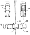
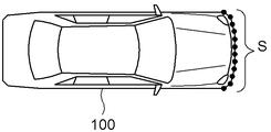
- the distance to the parked vehicle 100 is measured by the clearance sonar 33.
- the clearance sonar 33 measures the distance from the parked vehicle 100 according to the movement of the vehicle 90 and acquires the surface shape information S as shown in FIG.
- the surface shape information S of the parked vehicle 100 is discrete data corresponding to the moving distance of the vehicle 90.
- the moving speed, moving distance, and moving time of the vehicle 90 are determined linearly. For example, when the vehicle 90 moves at a constant speed, if it is measured according to a predetermined time interval, it is measured according to the moving distance.
- the ECU 9 can earn the moving speed and the moving distance of the vehicle 90 based on the detection result of the wheel speed sensor 23. Any method may be used as long as the surface shape information S can be obtained almost uniformly as a result.
- the vacant area detection unit 13 calculates the degree of matching between the bumper shape of the general vehicle stored in the program memory 6 and the surface shape information S. If it is determined that the surface shape information S corresponds to the bumper shape of the vehicle according to a predetermined standard, the area where the surface shape information S is present is detected as a “parked area (space)”. On the contrary, an area not corresponding to the “already parked area” is detected as an “empty area (space)”.
- FIG. 5 is an overhead view showing an example in which the “free space” is detected while the vehicle 90 passes through a passage of a parking lot such as a shopping center.
- a space where the parked vehicle 100 does not exist for example, a space between two parked vehicles 100 parked in the adjacent parking section, is also detected as an empty region in principle.
- a predetermined length along the traveling direction of the vehicle 90 in FIG. 5 is set as a threshold value, and it is detected that the area is not an already parked area over the threshold value, the area is an empty area. E is detected. Further, when it is detected that adjacent parking sections are not continuously parked areas, in principle, it is detected as an empty area E for one vehicle.
- the empty area E may be divided and provided with virtual boundaries to be set as a plurality of empty areas E.
- FIG. 6 schematically shows an example of the “vacant area E” and “already parked area F” thus detected. Since the empty area E is detected as the vehicle 90 moves, all of the empty area E existing within a predetermined range from the vehicle 90 is stored in the storage unit 16 having the work memory 7 or the like as a core.
- the area detection unit 11 is further configured to include a lane marking recognition unit 14, and by recognizing the lane marking W in the empty area E, as shown in FIG. Is detected. Image recognition of the lane marking W will be described later.
- the area detector 11 can detect a plurality of parking areas G where the vehicle 90 can be parked on at least one of the left and right sides of the vehicle 90.
- the reason why detection is possible is that detection is not possible unless the parking section is empty, and the area detection unit 11 is a functional unit that detects a plurality of parking areas G where the vehicle 90 can be parked.
- FIG. 7 shows an example in which a total of five parking areas G, three in the left direction of the vehicle 90 and two in the right direction, are detected.
- FIG. 8 shows an example in which an image captured by the camera 1 of the vehicle 90 at the position shown in FIG.
- a symbol V in FIG. 5 indicates a shooting range of the camera 1 mounted on the vehicle 90.
- the image displayed on the display unit 4a of the monitor device 4 is obtained by inverting the left and right mirror images of the captured image as shown in FIG. Become. That is, it is displayed so that the driver can obtain the same visual effect as when viewing the scene behind the vehicle 90 through the rearview mirror.
- the captured image is also used for image recognition of the lane marking W by the lane marking recognition unit 14.
- it is not necessary to use a mirror image for the image recognition of the lane marking W but here, in order to facilitate understanding, the image recognition of the lane marking W will be described using the same mirror image as the display of the monitor device 4. .
- the lane marking recognition unit 14 performs image recognition of the lane marking W on the captured image acquired by the captured image acquisition unit 15 from the camera 1. Prior to the image recognition of the lane marking W, the lane marking recognition unit 14 sets a region of interest ROI (region of interest) that is a target region for image processing as preprocessing.
- the region of interest ROI is set to an image region corresponding to the free region E detected by the free region detection unit 13. Since the empty area E and the region of interest ROI are concepts in image processing, it is not necessary to actually display them on the monitor device 4.
- FIG. 8 illustrates the procedure of image recognition.
- the lane marking recognition unit 14 performs image processing on the region of interest ROI, detects the lane marking W, and detects the parking area G (image recognition). A much smaller region is set as the region of interest ROI than the entire captured image, and the image recognition of the partition line W is executed in the region of interest ROI, so that the calculation load is reduced.
- FIG. 8 shows an example in which the region of interest ROI is set for one empty region E
- the region of interest ROI is similarly set for other empty regions E
- the partition line W is detected.
- the parking area G is detected.
- the vehicle 90 detects the empty area E while moving, and the shooting range V of the vehicle 90 also changes as the vehicle 90 moves. Accordingly, it is preferable to sequentially recognize the lane markings W with respect to the empty area E detected as the vehicle 90 moves and detect the parking area G. Further, all the parking possible areas G existing within a predetermined range from the vehicle 90 are stored in the storage unit 16 having the work memory 7 or the like as a core.
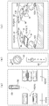
- the display control unit 17 displays the photographed image on the monitor device 4 and superimposes a graphic image indicating the parking target candidate H on the position corresponding to the parking available region G detected by the region detection unit 11 on the photographed image.
- FIG. 9 shows an example in which a plurality of parkingable regions G detected at a plurality of locations are displayed on the monitor device 4 as parking target candidates H.
- a plurality of parkingable regions G detected at a plurality of places are displayed on the monitor device 4 as a parking target candidate H superimposed on a captured image by a graphic image as shown by a broken line in the figure.
- the parking target candidate H is superimposed on the captured image as a yellow graphic image, for example.
- three parking target candidates H1, H2, and H3 are shown.
- the selection unit 18 is a functional unit that can select one of the parking target candidates H as a parking target (indicated by a symbol T in FIGS. 10 to 12) based on an instruction input from the driving device of the vehicle 90. .
- the driver can select one of a plurality of parking target candidates H by operating a steering wheel 51 (steering device) as one of the driving devices.
- FIG. 9A is an overhead view showing a part of the parking lot corresponding to FIG. As shown in FIG. 9 (a), the parked vehicle 100 is not parked in the parking target candidates H1 to H3 and is an empty section.
- FIG. 9B schematically shows the steering wheel 51 and the shift lever 55.
- FIG. 9B shows a state in which the vehicle 90 goes straight through the parking lot passage as shown in FIG.
- the display control unit 17 displays a plurality of parking target candidates H as graphic images, and the selection unit 18 selects one of the parking target candidates H as the parking target T.
- the parking target candidate H is not displayed as a graphic image, and the selection unit 18 also selects the parking target T from the parking target candidate H. Absent.
- the display control unit 17 may display one parking target candidate H as a graphic image, or display it as the parking target T from the beginning. Also good.
- the selection unit 18 selects whether the parking target candidate H is selected or left unselected. Is possible.
- the display control unit 17 displays the parking target T from the beginning when only one parking area G is detected, the function as the selection unit 18 is in a dormant state.
- FIG. 10 shows an example when the steering wheel 51 is operated in the right direction (arrow R direction).
- the parking target candidate H detected in the right direction of the vehicle 90 can be selected.
- the parking target candidate H2 is selected by operating the steering wheel 51 to the right direction by a predetermined amount or more. Is done.
- the selected parking target candidate H2 is superimposed and displayed as a parking target T as a graphic image in a form different from the other parking target candidates H1 and H3 as shown by a solid line in FIG.
- the selected parking target candidate H2 is superimposed on the captured image as a green graphic image.
- the vehicle 90 is parked along a route as indicated by a broken line in FIG.
- the front wheel 53 which is a steered wheel, is steered in a direction corresponding to the broken line path.
- the operation amount of the steering wheel 51 in the right direction is preferably an operation amount that realizes a steering angle corresponding to a parking route as indicated by a broken line in FIG.
- this operation amount includes the case where the steering wheel 51 is rotated one or more times.
- the determination unit 19 is a functional unit that determines the selected (set) parking target T as a parking assistance target.
- a guide unit (not shown) of the ECU 9 calculates the parking route and the steering angle to guide the vehicle 90. This guidance includes guidance by automatic steering and guidance for instructing the steering amount and steering direction of the driver by voice, text, or graphics.
- the final determination of the selected parking target candidate H as the parking target T is that the vehicle 90 starts traveling by creeping by operating a determination button (not shown) displayed on the touch panel 4b or by the driver loosening the brake pedal. Depends on what has been done. These determinations based on the behavior of the vehicle 90 are performed based on detection results of the brake sensor 27, the wheel speed sensor 23, and the like.
- the driver may determine that the selection of the parking target candidate H has been completed because the driver loosens or does not hold the steering wheel 51 and determines the parking target T as the parking target T.
- Such determination based on the behavior of the driver with respect to the steering wheel 51 is performed based on detection results of the steering sensor 21, the torque sensor 22, and the like.
- FIG. 11 shows an example in which the steering wheel 51 is operated in the left direction (arrow L direction).
- the parking target candidate H detected in the left direction of the vehicle 90 can be selected.
- two parking target candidates H are detected in the left direction of the vehicle 90, that is, a parking target candidate H ⁇ b> 3 that is relatively closer to the vehicle 90 and a farther parking target candidate H ⁇ b> 1.
- the parking target candidate H1 far from the vehicle 90 is selected.
- the selected parking target candidate H1 is superimposed and displayed as a parking target T as a graphic image in a form different from the other parking target candidates H2 and H3, for example, a green graphic image, as shown by the solid line in FIG.
- the parking target candidate H1 is determined as a parking target, the vehicle 90 is parked along a route as indicated by a broken line in FIG.
- the front wheel 53 which is a steered wheel, is steered in a direction corresponding to the broken line path.
- the operation amount of the steering wheel 51 to the left when selecting the parking target candidate H1 is preferably an operation amount that realizes a steering angle corresponding to the parking route as shown by a broken line in FIG. is there.
- FIG. 12 shows an example when the steering wheel 51 is operated in the left direction (arrow L direction) as in FIG.
- the parking target candidate H detected in the left direction of the vehicle 90 can be selected.
- two parking target candidates H are detected in the left direction of the vehicle 90, that is, a parking target candidate H ⁇ b> 3 that is relatively close to the vehicle 90 and a parking target candidate H ⁇ b> 1 that is far away.
- the parking target candidate H3 closer to the vehicle 90 is selected by operating the steering wheel 51 to the left more than a relatively large operation amount, that is, a second predetermined amount greater than the first predetermined amount.
- the selected parking target candidate H3 is superimposed and displayed as a parking target T as a graphic image in a form different from the other parking target candidates H1 and H2, as shown by a solid line in FIG.
- the parking target candidate H3 is determined as a parking target, the vehicle 90 is parked along a route as indicated by a broken line in FIG.
- the curvature in this route is larger than the parking route to the parking target candidate H1 far from the vehicle 90. Therefore, parking on the side closer to the vehicle 90 due to an operation amount (second predetermined amount) larger than the operation amount (first predetermined amount) of the steering wheel 51 when selecting the parking target candidate H1 far from the vehicle 90.
- a target candidate H3 is selected. That is, when the parking target candidate H3 is selected, the operation amount of the steering wheel 51 in the left direction is preferably an operation amount that realizes a steering angle corresponding to the parking route as indicated by a broken line in FIG. is there.
- a plurality of parking target candidates H are detected, and one of them can be selected by operating the steering wheel 51.
- a plurality of parking target candidates H can be detected on either the left or right side of the vehicle 90, and one of them can be selected by operating the driving device (for example, the steering wheel 51).
- the display control unit 17 superimposes a plurality of graphic images indicating the parking target candidates H at positions corresponding to the respective parkingable regions G on the photographed image when the plurality of parkingable regions G are detected by the region detection unit 11.
- the selection unit 18 includes not only selection of the left or right parking target candidate H of the vehicle 90 but also selection from the parking target candidates H set at a plurality of locations in the same direction of either the left or right of the vehicle 90.
- one of the plurality of parking target candidates H is selected as the parking target T based on the instruction input from the driving device.
- FIG. 13 is a flowchart schematically showing a series of processes from detection of the empty area E to selection of the parking target candidate H.
- the vehicle 90 detects the empty area E as it moves (# 1). All empty areas E existing within a predetermined range from the vehicle 90 are accumulated and held in the accumulation unit 16 having the work memory 7 or the like as a core. That is, the detection result is held (# 2).
- a region of interest ROI is set as shown in FIG. 8, the lane marking W is image-recognized, and a parking area G is detected as shown in FIG. 3).
- This detection result is also held. That is, all the parking possible areas G existing within a predetermined range from the vehicle 90 are accumulated and held in the accumulation unit 16 having the work memory 7 as a core (# 4).
- the image recognition of the lane marking W is performed for the entire captured image or the region of interest ROI set as a predetermined area for the vehicle 90 on the captured image. Executed. Further, when a vacant area E is detected, such as a parking lot where no lane line W exists, and a lane line W is not detected, a parking area G is set according to the vacant area E.
- step # 5 it is determined based on the detection result of the shift lever switch 25 whether or not the shift lever 55 is reverse. Steps # 1 to # 4 are repeated until the shift lever 55 is set to reverse. That is, since the storage unit 16 holds a vacant area E and a parking area G existing within a predetermined range from the vehicle 90, when the vehicle 90 is moving, a new vacant space is sequentially added according to the movement. The area E and the parking area G are detected, and the retained data is updated. At that time, due to the movement of the vehicle 90, the empty area E and the parking available area G that are no longer in the predetermined range from the vehicle 90 are discarded.
- step # 5 If it is determined in step # 5 that the shift lever 55 is reverse, the available parking area G held in the storage unit 16 is set as the parking target candidate H. Then, as shown in FIG. 9, it is displayed as a graphic image together with the photographed image on the monitor device 4 (# 6).
- the parking target candidate H selected according to the steering direction and the steering amount is displayed (# 7, # 8).
- the steering wheel 51 which is a steering device
- the driving device is not limited to the steering device, and the steering device is not limited to the steering wheel 51.
- a stick handle may be used as a steering device, but the parking target candidate H may be selected using such a stick handle.
- the parking target candidate H may be selected using the direction indicator as the driving device. For example, when the direction indicator is operated in the left direction and is operated in the left direction again as it is, it is counted twice and the second parking target candidate H from the side far from the vehicle 90 is selected. At this time, since the direction indicator remains operated to the left, it also notifies the outside of the vehicle 90 that the vehicle is moving in the left direction. The same applies to the right direction.
- the case where the parking target candidate H closer to the vehicle 90 is selected as the amount of operation of the steering wheel 51 is increased has been described as an example.
- the operation amount of the steering wheel 51 when selecting the parking target candidate H is an example in which the amount of operation corresponds to the initial steering angle when the parking target candidate H is the parking target T. Although described, of course, it need not be limited thereto.
- the operation amount of the steering wheel 51 when selecting the parking target candidate H may be unrelated to the steering angle at the time of guidance in parking assistance.
- the selection unit 18 selects the parking target candidate H corresponding to the detected parking area G.
- the parking target candidate H in the direction corresponding to the steering direction of the steering wheel 51 is selected as the parking target T (for example, FIGS. 9 to 12).
- the parking target candidate H to be selected may be selected.
- the selection unit 18 selects the parking target candidate H that exists in the steering direction by the steering wheel 51 as the parking target T regardless of whether the parking area G is detected on both the left and right sides of the vehicle 90. Good.
- the parking target T when the vehicle is steered in a direction in which the parking area G is not detected, no parking target candidate H is selected as the parking target T, and when the vehicle is steered in the direction in which the parking area G is detected.
- One of the parking target candidates H is selected as the parking target T.
- the steering direction does not necessarily coincide with the direction of the selected parking target candidate H. May be.
- the configuration in which the parking target T is selected based on, for example, the steering amount without being restricted in the steering direction is not hindered.
- Monitor device 11 Area detection unit 15: Captured image acquisition unit 17: Display control unit 18: Selection unit 51: Steering wheel (driving device, steering device) 90: Vehicle G: Parking available area H: Parking target candidate T: Parking target
Abstract
車両を駐車可能な駐車可能領域を、車両の左右の少なくとも一方の側において複数箇所検出可能な領域検出部を有し、駐車可能領域を含み、車両の周辺の情景が撮影された撮影画像をモニタ装置に表示させると共に、領域検出部により検出された駐車可能領域が撮影画像上において対応する全ての位置に駐車目標候補を示すグラフィック画像を重畳させ、車両の運転装置からの指示入力に基づいて駐車目標候補の内の1つを駐車目標として選択可能とする。
Description
本発明は、車両の駐車時の運転操作を支援する駐車支援装置に関する。
駐車時の運転操作を支援する駐車支援装置として、設定された駐車目標位置に対して自動的に操舵を行って車両を誘導するシステムや、ドライバーに操舵方向や操舵量を指示するシステムなどが実用化されている。従来、駐車目標位置の設定に際しては、車内に設けられた設定スイッチやタッチパネル付きのモニタ装置などの入力手段をドライバーが操作する必要があった。これに対し、これら通常の運転操作には用いない入力手段を介することなく駐車目標位置を設定可能な駐車支援装置が提案されている。特開2008-201363号公報(特許文献1)には、ドライバーによるステアリングホイールの操作に基づいて駐車形態及び駐車目標位置を設定する駐車支援装置が記載されている。これによれば、ステアリングホイールが左右の何れかに所定量以上操作された際には、左右何れかへの車庫入れ駐車に対応する駐車目標位置が設定される。ステアリングホイールが左右の何れにも所定量以上操作されない場合には、左方向への縦列駐車に対応する駐車目標が設定される(特許文献1:図5及び図9、第27~36段落等。)。
但し、設定される駐車目標位置は、駐車支援装置が車両の位置に対して自動的に設定したものである(特許文献1:図7等)。このため、ドライバーは車両に対する駐車目標位置を高い自由度で選択することはできない。例えば、ショッピングセンターの駐車場などにおいて複数の駐車区画が空いており、出入り口に近い区画に駐車したい場合であっても、車両との位置関係においてドライバーが所望する区画とは異なる区画が設定される場合がある。つまり、特許文献1の駐車支援装置は、複数の駐車目標位置を選択可能ではあっても、それらは駐車形態と駐車目標位置とが1対1で対応したものである。即ち、駐車形態は選択可能ではあっても、各駐車形態において駐車目標位置は一義的に定められ、任意の駐車目標位置が選択可能なものではない。
尚、駐車目標位置の設定は、特許文献1のように車両の位置に対して設定されるものには限定されない。例えば、特開2007-290557号公報(特許文献2)に記載されているように、ソナーなどを利用して走行中に空き空間を検出する方法や、駐車区画を示す白線を画像認識する方法などもある(特許文献2:図2、図5、第27、第45段落等)。しかし、何れもドライバーが通常の運転操作には用いない入力手段を介することなく任意の駐車目標位置を簡単に設定できるものではない。特許文献2では、第1目標駐車位置と第2目標位置とが選択可能とされており、ソナーなどを利用して走行中に検出した空き空間と、白線を画像認識した駐車区画とが選択可能である。しかし、この選択は検出結果の確からしさに基づいて、駐車支援装置が自動的に行うものでもあり、ドライバーが任意に所望の駐車目標位置を設定可能なシステムではない。
上記背景に鑑みて、ドライバーが通常の運転操作には用いない入力手段を介することなく高い自由度を持って駐車目標位置を簡単に設定可能とすることが求められる。
上記課題に鑑みた本発明に係る駐車支援装置の特徴構成は、
車両を駐車可能な駐車可能領域を、前記車両の左右の少なくとも一方の側において複数箇所検出可能な領域検出部と、
前記車両の周辺の情景が撮影された撮影画像を取得する撮影画像取得部と、
前記撮影画像をモニタ装置に表示させると共に、前記領域検出部により検出された前記駐車可能領域が前記撮影画像上において対応する位置に駐車目標候補を示すグラフィック画像を重畳させる表示制御部と、
前記車両の運転装置からの指示入力に基づいて前記駐車目標候補の内の1つを駐車目標として選択可能な選択部と、を備える点にある。
車両を駐車可能な駐車可能領域を、前記車両の左右の少なくとも一方の側において複数箇所検出可能な領域検出部と、
前記車両の周辺の情景が撮影された撮影画像を取得する撮影画像取得部と、
前記撮影画像をモニタ装置に表示させると共に、前記領域検出部により検出された前記駐車可能領域が前記撮影画像上において対応する位置に駐車目標候補を示すグラフィック画像を重畳させる表示制御部と、
前記車両の運転装置からの指示入力に基づいて前記駐車目標候補の内の1つを駐車目標として選択可能な選択部と、を備える点にある。
この特徴構成によれば、ドライバーは、通常の運転操作の姿勢を大きく崩すことなく、所望の駐車位置を選択することができる。例えばタッチパネルなどを改めて操作することなく、通常の運転操作に準じた操作により駐車位置を選択することができる。
また、本発明に係る駐車支援装置の前記選択部は、前記車両に対して左右の少なくとも一方において複数存在する前記駐車目標候補の内の1つを前記駐車目標として選択可能であると好適である。ドライバーは車両の左右の内、車両を停めたい方向において複数の駐車位置が空いている場合に、所望の駐車位置を選択することができる。例えば、ショッピングセンターなどにおいて入り口に近い位置に駐車したい場合に有用である。
ここで、前記運転装置は、前記車両の操舵装置であると好適である。車両を運転する際、ドライバーは操舵装置を保持しているから、所望の駐車位置を選択するに際して無駄が無く、操作が非常に簡便となる。また、駐車の際には車両を旋回させるための操舵が必要であるが、その際の操舵の少なくとも一部を駐車目標位置の選択の際に実行することができる。つまり、車両が動き始める際の初期舵角の幾分かを、駐車目標位置の選択の際に進めておくことができるので、駐車目標位置を選択した後の駐車に要する時間が短縮される。
また、本発明に係る駐車支援装置の前記選択部は、前記操舵装置による操舵方向に存在する前記駐車目標候補を前記駐車目標として選択すると好適である。特に、前記領域検出部が前記車両の左右両方において前記駐車可能領域を検出した場合、前記選択部は、検出された前記駐車可能領域に対応する前記駐車目標候補の内、前記操舵装置の操舵方向に対応した方向の前記駐車目標候補を前記駐車目標として選択すると好適である。上述したように、駐車の際には車両を旋回させるための操舵が必要であるが、その際の操舵方向に基づいて、駐車目標位置を選択することができる。駐車目標位置の選択の際の操舵は、車両が動き始める際の初期舵角の幾分かに充当できるので、駐車目標位置を選択した後の駐車に要する時間が短縮される。
尚、車両の左右両方において駐車可能領域が検出されていない場合、つまり、左右何れか一方においてのみ駐車可能領域が検出されている場合であっても、操舵装置による操舵方向に存在する駐車目標候補が選択されてもよい。即ち、車両の左右両方において駐車可能領域が検出されているか否かに拘わらず、本発明に係る駐車支援装置の前記選択部は、前記操舵装置による操舵方向に存在する前記駐車目標候補を前記駐車目標として選択するものであってよい。この場合、駐車可能領域が検出されていない方向へ操舵された際には何れの駐車目標候補も選択されず、駐車可能領域が検出されている方向へ操舵された際に何れかの駐車目標候補が選択されることになる。これにより、左右何れか一方においてのみ駐車可能領域が検出されている場合であっても、車両を旋回させるための操舵方向と同じ方向への操舵によって駐車目標を選択することが可能となる。
また、本発明に係る駐車支援装置の前記選択部は、前記操舵装置の操作量に基づき、当該操作量が多いほど前記車両に近い位置の前記駐車目標候補を前記駐車目標として選択すると好適である。操舵装置の操舵量が大きいと車両はより大きく旋回する。このため、より車両に近い位置への駐車に好適となる。従って、操作量が多いほど車両に近い位置の駐車目標候補を駐車目標として選択すると好適である。特に、この操作量(操舵量)による選択と上述した操舵方向による選択とを組み合わせることによって、駐車のための操作(操舵)と、駐車目標の選択のための操作(操舵)とが良好に適合される。従って、ドライバーは、広範な範囲において検出された駐車可能領域に対応する駐車目標候補から、通常の運転操作に準じた操作により所望の駐車目標を選択することが可能となる。即ち、ドライバーは通常の運転操作に用いる運転装置を入力手段として、高い自由度を持って駐車目標位置を簡単に設定することが可能となる。
駐車目標が決定すると、駐車支援装置は駐車目標へ駐車経路を演算して、その駐車経路に沿った誘導を行う。駐車経路の演算における初期条件として操舵輪の操舵角、つまり操舵装置の操作量が必要となる。このことから、前記駐車目標が選択されたときの前記操舵装置の操作量が前記駐車目標への駐車経路に沿った誘導時の初期舵角として扱われるような構成を採用すると、駐車目標が選択されると直ちに誘導を開始することが可能となり、好都合である。
駐車場での一般的な駐車プロセスの1つでは、空いている駐車区画を探しながら駐車場走行路を通り、見つけた駐車区画をバックミラーで確認して、後進駐車を始める。このような駐車プロセスに本発明を適用する場合、前記モニタ装置に表示される撮影画像が前記車両の後方を撮影した画像を左右鏡像反転させたものとし、前記撮影画像に重畳された駐車目標候補の内の1つが駐車目標として選択されるように構成するとよい。このように構成することで、後退駐車時に、モニタ装置において操舵方向に存在する駐車目標候補を駐車目標として選択したときの操舵が、車両が動き始める際の初期舵角の幾分かに充当されることになるので、好都合である。
以下、本発明に係る駐車支援装置の実施形態を図面に基づいて説明する。図1に示すように、駐車支援装置10には、画像認識や進路予想などの高度な演算処理を行い、駐車支援装置10の中核を担うCPU(central processing unit)5が備えられている。CPU5は、プログラムメモリ6に格納されたプログラムやパラメータを利用して各種演算処理を実行する。また、CPU5は、必要に応じてワークメモリ7に一次的に撮影画像などを格納して演算を実行する。ここでは、プログラムメモリ6やワークメモリ7が、CPU5とは別のメモリである例を示しているが、CPU5と同一のパッケージ内に集積されていてもよい。駐車支援装置10は、CPU5やメモリ、その他の周辺回路と共に、運転支援ECU(electronic control unit)9として構成される。駐車支援装置10の各機能部は、ハードウェアとソフトウェアとの協働によって実現される。本例では、CPU5を中核としたが、駐車支援装置10は、DSP(digital signal processor)など、他の論理演算プロセッサや論理回路を中核として構成されてもよい。
図1に示すように、カメラ1(車載カメラ)により撮影された画像は、スーパーインポーズ部2a、グラフィック描画部2b、フレームメモリ2cなどを有する画像処理モジュール2を介して、モニタ装置4に表示される。画像処理モジュール2は、CPU5やプログラムメモリ6などと同様に、本発明の撮影画像取得部15並びに表示制御部17として機能する(図2参照。)。カメラ1は、CCD(charge coupled device)やCIS(CMOS image sensor)などの撮像素子を用いて、毎秒15~30フレームの2次元画像を時系列に撮影し、デジタル変換して動画データ(撮影画像)を出力するデジタルカメラである。各フレームの2次元画像は、フレームメモリ2cに格納され、フレームごとに画像処理やグラフィックの重畳を施されることが可能である。グラフィック描画部2bへの描画指示や、スーパーインポーズ部2aへのグラフィック重畳指示は、CPU5から発せられる。
モニタ装置4は、例えば、ナビゲーションシステムのモニタ装置が兼用される。図1に示すように、モニタ装置4は、表示部4aと、表示部4aに形成されたタッチパネル4bと、スピーカ4cとを有している。表示部4aは、画像処理モジュール2から提供されるカメラ1の撮影画像や、グラフィック画像、それらが合成された合成画像などを表示する。一例として、表示部4aは液晶ディスプレイによって構成される。タッチパネル4bは、表示部4aと共に形成され、指などによる接触位置をロケーションデータとして出力することができる感圧式や静電式の指示入力装置である。図1においては、スピーカ4cは、モニタ装置4に備えられている場合を例示しているが、スピーカ4cはドアの内側など、他の場所に備えられても良い。スピーカ4cは、CPU5の指示に応じて音声処理モジュール3から提供される音声を出力する。尚、CPU5は、単純にブザー8を介して報知音を鳴らす場合もある。
CPU5は、図1において符号50で示す車内ネットワークを介して種々のシステムやセンサと通信可能に接続されている。本実施形態においては、車内ネットワークとしてCAN(controller area network)50を例示している。図1に示すように、駐車支援装置10(CPU5)は、車内のパワーステアリングシステム31やブレーキシステム37と接続される。これら各システムは、駐車支援装置10と同様にCPUなどの電子回路を中核として構成され、運転支援ECU9と同様に周辺回路と共に構成されたECUを中核として構成される。
パワーステアリングシステム31は、電動パワーステアリング(EPS : electric powersteering)システムやSBW(steer-by-wire)システムである。このシステムは、ドライバーにより操作されるステアリングホイールにアクチュエータ41によりアシストトルクを付加する他、ステアリングホイールや操舵輪をアクチュエータ41により駆動することによって自動操舵を行う。ブレーキシステム37は、ブレーキのロックを抑制するABS(anti lock braking system)や、コーナリング時の車両の横滑りを抑制する横滑り防止装置(ESC : electronic stability control)、ブレーキ力を増強させるブレーキアシストなどを有した電動ブレーキシステムや、BBW(brake-by-wire)システムである。このシステムは、アクチュエータ47を介して車両90に制動力を付加することができる。
図1において、各種センサの一例として、ステアリングセンサ21や車輪速センサ23、シフトレバースイッチ25、アクセルセンサ29がCAN50に接続されている。ステアリングセンサ21は、ステアリングホイールの操舵量(回転角度)を検出するセンサであり、例えばホール素子などを用いて構成される。駐車支援装置10は、ドライバーによるステアリングホイールの操舵量や、自動操舵時の操舵量をステアリングセンサ21から取得して各種制御を実行する。
車輪速センサ23は、車両90の車輪の回転量や単位時間当たりの回転数を検出するセンサであり、例えばホール素子などを用いて構成される。駐車支援装置10は、車輪速センサ23から取得した情報に基づいて車両90の移動量などを演算し、各種制御を実行する。車輪速センサ23は、ブレーキシステム37に備えられている場合もある。ブレーキシステム37は、左右の車輪の回転差などからブレーキのロックや、車輪の空回り、横滑りの兆候などを検出して、各種制御を実行する。車輪速センサ23がブレーキシステム37に備えられている場合には、駐車支援装置10は、ブレーキシステム37を介して情報を取得する。ブレーキセンサ27は、ブレーキペダルの操作量を検出するセンサであり、
駐車支援装置10は、ブレーキシステム37を介して情報を取得する。駐車支援装置10は、例えば、自動操舵中にブレーキペダルが踏み込まれたような場合に、自動操舵に不都合な環境下にあるとして自動操舵を中断したり中止したりする制御を行うことができる。
駐車支援装置10は、ブレーキシステム37を介して情報を取得する。駐車支援装置10は、例えば、自動操舵中にブレーキペダルが踏み込まれたような場合に、自動操舵に不都合な環境下にあるとして自動操舵を中断したり中止したりする制御を行うことができる。
シフトレバースイッチ25は、シフトレバーの位置を検出するセンサ又はスイッチであり、変位センサなどを用いて構成される。駐車支援装置10は、例えば、シフトがリバースにセットされた場合に支援制御を開始したり、リバースから前進に変更された場合に支援制御を終了させたりすることができる。
また、ステアリングホイールへの操作トルクを検出するトルクセンサ22は、ドライバーがステアリングホイールを握っているか否かについても検出することが可能である。駐車支援装置10は、自動操舵中にドライバーがステアリングホイールを操作するために強く握った場合などに、自動操舵に不都合な環境下にあるとして自動操舵を中断したり中止したりする制御を行うことができる。また、自動操舵時には、一般的にエンジンのアイドリングによる車両90のクリーピングが利用される。従って、ドライバーがアクセルを操作したことがアクセルセンサ29により検出された場合、駐車支援装置10は、自動操舵に不都合な環境下にあるとして自動操舵を中断したり中止したりする制御を行うことができる。
図1に示す各種システムやセンサ、これらの接続形態については一例であり、他の構成や接続形態が採用されてもよい。また、上述したように、センサは直接CAN50に接続されても良いし、種々のシステムを介して接続されてもよい。
上述したように、駐車支援装置10は、CPU5を中核として構成され、プログラムメモリ6に格納されたプログラム(ソフトウェア)と協働して駐車支援のための種々の演算を実施する。駐車支援の種類としては、
(1)車内に搭載されたモニタ上に車両後方の映像を映し出すと共に、車幅延長線や予想進路線などのガイド線を重畳表示させるもの、
(2)駐車目標を設定し、音声などによりドライバーの操作を指示して誘導するもの、
(3)さらに、ドライバーが速度調整だけを担い、自動操舵により駐車目標へ誘導するもの、などがある。(2)及び(3)では、駐車目標が設定されるが、この駐車目標の検出についても、様々な手法がある。例えば、
(a)駐車目標位置を通過した際に、ソナー(クリアランスソナー33)などで空き領域を検出して自動認識し、駐車目標を検出するもの、
(b)例えば区画線を画像認識して駐車目標を検出するもの、
(c)精度向上のために、上記(a)や(b)など複数の手法を複合させたもの、
などがある。
本実施形態では、上記(3)のように、ドライバーが速度調整だけを担い、自動操舵により駐車目標へ車両を誘導する駐車支援装置を例として説明する。また、本実施形態では、上記(c)のように、ソナー等による空き領域検出と、区画線の画像認識とを複合させて駐車目標を検出する構成を例として説明する。しかし、当然ながら、ドライバーが手動で操舵するような駐車支援装置において本発明を適用することも可能である。また、ソナーや撮影画像を単独で利用する手法や別の手法により駐車目標位置が検出される場合にも、本発明を適用することが可能である。従って、以下に説明する実施形態は、一例であって、本発明を限定するものではない。
上述したように、駐車支援装置10はCPU5を中核としたECU9として構成され、ハードウェアとソフトウェアとの協働によってその機能が達成される。図2は、駐車支援装置10の機能構成の一例をブロック図により模式的に示したものである。各機能部も、ハードウェアとソフトウェアとの協働によってその機能が達成されるものであり、ECU9において必ずしもそれぞれ独立して設けられなくてよい。図2に示すように、駐車支援装置10は、領域検出部11と、撮影画像取得部15と、蓄積部16と、表示制御部17と、選択部18と、決定部19とを有して構成される。領域検出部11は、距離データ取得部12と、空き領域検出部13と、区画線認識部14とを有して構成される。
以下、各機能部について説明する。領域検出部11は、車両90を駐車可能な駐車可能領域(後述する符号G)を複数箇所検出可能な機能部である。尚、ここで、複数箇所検出可能とは、車両90の左右の少なくとも一方の側において複数箇所の駐車可能領域Gを検出可能であることをいう。例えば、車両90の左方向において2箇所の駐車可能領域Gを検出したり、車両90の右方向において2箇所の駐車可能領域Gを検出したり、車両90の左方向において2箇所、車両90の右方向において1箇所の合計3箇所の駐車可能領域Gを検出したりすることが可能である。当然ながら、左右の両方向において2箇所以上、合計4箇所以上の駐車可能領域Gを検出することも可能である。
上述したように、領域検出部11は、距離データ取得部12と空き領域検出部13とを有している。距離データ取得部12は、クリアランスソナー33などの距離センサの検出結果を取得する機能部であり、空き領域検出部13は、距離センサの検出結果に基づいて空き領域を検出する機能部である。以下、他の車両を認識することによって駐車のための空き領域を検出する場合を例として説明する。図3に示すように、車両90には、側方に向けてポイントセンサとしてのクリアランスソナー33(距離センサ)が搭載されている。シングルービームセンサやレーザレーダなど、他の距離センサが搭載されていてもよい。車両90は、駐車中の他の車両100(以下、駐車車両と称す。)のそばを通過する際に、クリアランスソナー33によって駐車車両100までの距離を計測する。例えば、クリアランスソナー33は、車両90の移動に応じて駐車車両100との距離を計測し、図4に示すような表面形状情報Sを取得する。
駐車車両100の表面形状情報Sは、車両90の移動距離に応じた離散的なデータである。尚、車両90の移動速度、移動距離、移動時間は、線形的に定まる。例えば、車両90が等速で移動する場合には、所定時間間隔に応じて計測すれば、移動距離に応じて測定することになる。車両90の移動速度や移動距離は、車輪速センサ23の検出結果に基づいてECU9が所得可能である。結果として概ね均等に表面形状情報Sを得ることができる方法であれば、どのような方法を用いてもよい。
空き領域検出部13は、プログラムメモリ6などに記憶された一般的な車両のバンパー形状と表面形状情報Sとの適合度合いを演算する。そして、所定の基準に応じて、表面形状情報Sが車両のバンパー形状に相当すると判定された場合には、当該表面形状情報Sが存在する領域を「既駐車領域(空間)」として検出する。反対に、「既駐車領域」に相当しない領域については、「空き領域(空間)」として検出する。
図5は、例えばショッピングセンターなどの駐車場の通路を車両90が通過しながら「空き領域」を検出する例を俯瞰図により示している。駐車車両100が存在しない空間、例えば、隣接する駐車区画に駐車された2台の駐車車両100の間の空間も原理的には空き領域として検出される。しかし、図5における車両90の進行方向に沿う所定の長さをしきい値として、そのしきい値以上に長さに亘って既駐車領域ではないことが検出された場合に当該領域が空き領域Eとして検出される。また、隣接する駐車区画が連続して既駐車領域ではないことが検出された場合には、原理的には1台分の空き領域Eとして検出される。但し、そのように広い空き領域Eを検出した後に、当該空き領域Eを分割して仮想的な境界を設けて複数箇所の空き領域Eとして設定してもよい。図6は、そのようにして検出された「空き領域E」及び「既駐車領域F」の一例を模式的に示している。尚、空き領域Eは車両90の移動に伴って検出されるので、車両90から所定の範囲内に存在する空き領域Eは、全てワークメモリ7などを中核とする蓄積部16に蓄積される。
距離データ取得部12と空き領域検出部13とを用いて複数の空き領域Eを検出し、これを駐車可能領域Gとして設定することも可能である。しかし、本実施形態においては、領域検出部11がさらに区画線認識部14を有して構成され、空き領域Eにおける区画線Wを画像認識することによって、図7に示すように駐車可能領域Gを検出する。区画線Wの画像認識については後述する。図3~図7に基づいて上述したように、領域検出部11は、車両90を駐車可能な駐車可能領域Gを車両90の左右の少なくとも一方の側において複数箇所検出可能である。ここで、検出可能としたのは、駐車区画が空いていなければ検出できないからであり、領域検出部11は、車両90を駐車可能な駐車可能領域Gを複数箇所検出する機能部である。図7には、車両90の左方向において3箇所、右方向において2箇所の合計5箇所の駐車可能領域Gが検出された例を示している。
ところで、上述したように、カメラ1により撮影された撮影画像は、画像処理モジュール2を介してモニタ装置4に表示される。図8は、図5に示す位置にある車両90のカメラ1による撮影画像がモニタ装置4に表示された例を示している。図5における符号Vは、車両90に搭載されたカメラ1の撮影範囲を示している。尚、モニタ装置4はドライバーの着座位置よりも前方に配置されているので、モニタ装置4の表示部4aに表示される画像は、図8に示すように撮影画像を左右鏡像反転させたものとなる。つまり、ドライバーがルームミラーを介して車両90の後方の情景を見る場合と同様の視覚効果を得られるように表示される。撮影画像は、区画線認識部14による区画線Wの画像認識にも利用される。当然ながら、区画線Wの画像認識には鏡像画像を用いる必要はないが、ここでは理解を容易にするためにモニタ装置4の表示と同じ鏡像画像を用いて区画線Wの画像認識を説明する。
区画線認識部14は、撮影画像取得部15がカメラ1から取得した撮影画像上で、区画線Wの画像認識を行う。区画線認識部14は、区画線Wの画像認識に先立ち、前処理として画像処理の対象領域である関心領域ROI(region of interest)を設定する。関心領域ROIは、空き領域検出部13により検出された空き領域Eに相当する画像領域に設定される。空き領域E及び関心領域ROIは画像処理上の概念であるから、実際にモニタ装置4に表示する必要はない。ここでは、画像認識の手順を説明するために図8に図示している。区画線認識部14は、関心領域ROIに対して画像処理を行って、区画線Wを検出して駐車可能領域Gを検出する(画像認識する)。撮影画像の全体に比べて、遙かに小さい領域が関心領域ROIとして設定され、当該関心領域ROIの中で区画線Wの画像認識が実行されるので演算負荷が軽減される。
図8では、1箇所の空き領域Eに対して関心領域ROIを設定した例を示しているが、他の空き領域Eに対しても同様に関心領域ROIが設定され、区画線Wを検出することにより駐車可能領域Gが検出される。上述したように、車両90は移動しながら、空き領域Eを検出し、車両90の撮影範囲Vも車両90の移動と共に変化する。従って、車両90の移動に伴って検出される空き領域Eに対して順次、区画線Wの認識を実施して、駐車可能領域Gを検出すると好適である。また、車両90から所定の範囲内に存在する駐車可能領域Gは、全てワークメモリ7などを中核とする蓄積部16に蓄積される。
表示制御部17は、撮影画像をモニタ装置4に表示させると共に、領域検出部11により検出された駐車可能領域Gが撮影画像上において対応する位置に駐車目標候補Hを示すグラフィック画像を重畳させる機能部である。図9は、複数箇所検出された駐車可能領域Gが駐車目標候補Hとしてモニタ装置4に表示された例を示している。図9(c)に示すように、複数箇所検出された駐車可能領域Gは、図において破線で示すようなグラフィッ
ク画像により駐車目標候補Hとして撮影画像上に重畳されてモニタ装置4に表示される。駐車目標候補Hは、例えば黄色のグラフィック画像として撮影画像上に重畳される。図9では、3つの駐車目標候補H1,H2,H3が示されている。
ク画像により駐車目標候補Hとして撮影画像上に重畳されてモニタ装置4に表示される。駐車目標候補Hは、例えば黄色のグラフィック画像として撮影画像上に重畳される。図9では、3つの駐車目標候補H1,H2,H3が示されている。
選択部18は、車両90の運転装置からの指示入力に基づいて駐車目標候補Hの内の1つを駐車目標(図10~図12に符号Tで示す。)として選択可能な機能部である。ドライバーは、運転装置の1つとしてのステアリングホイール51(操舵装置)を操作することによって、複数の駐車目標候補Hから1つを選択することができる。図9(a)は、図5に対応して駐車場の一部を示す俯瞰図である。図9(a)に示すように駐車目標候補H1~H3には駐車車両100は駐車されておらず空き区画である。図9(b)は、ステアリングホイール51とシフトレバー55とを模式的に示している。図9(b)は、車両90が駐車場の通路を図5に示すように直進して停車し、シフトレバー55がリバースにセットされた状態を示しており、ステアリングホイール51は中立位置である。従って、図9(c)に示すように、複数箇所検出された駐車可能領域G(駐車目標候補H)は何れも選択されてはおらず、全ての駐車目標候補Hが未選択状態の黄色のグラフィック画像で示されている。
表示制御部17は、複数の駐車目標候補Hをグラフィック画像として表示させ、選択部18は、駐車目標候補Hの内の1つを駐車目標Tとして選択する。当然ながら、領域検出部11により駐車可能領域Gが検出されなかった場合には、駐車目標候補Hはグラフィック画像として表示されず、選択部18も駐車目標候補Hから駐車目標Tを選択することはない。領域検出部11により駐車可能領域Gが1つだけ検出された場合、表示制御部17は、1つの駐車目標候補Hをグラフィック画像として表示させてもよいし、当初から駐車目標Tとして表示させてもよい。選択部18は、表示制御部17が1つの駐車目標候補Hをグラフィック画像として表示させた場合には、当該駐車目標候補Hを選択するか、未選択状態のままとするかの選択を行うことが可能である。駐車可能領域Gが1つだけ検出された場合に表示制御部17が当初から駐車目標Tとして表示させる場合には、選択部18としての機能は休止状態となる。
以下、図10~図12を利用して、図9に示す駐車目標候補H1~H3の内の1つを選択する例について説明する。図10は、ステアリングホイール51が右方向(矢印R方向)に操作された場合の例を示している。ステアリングホイール51が右方向に操作されることによって、車両90の右方向において検出されている駐車目標候補Hが選択可能となる。図9及び図10においては、車両90の右方向には1つの駐車目標候補H2のみが検出されているので、ステアリングホイール51が所定量以上右方向に操作されることによって駐車目標候補H2が選択される。選択された駐車目標候補H2は、駐車目標Tとして図10において実線で示すように他の駐車目標候補H1,H3とは異なる形態のグラフィック画像として重畳表示される。例えば、選択された駐車目標候補H2は、緑色のグラフィック画像として撮影画像上に重畳される。当該駐車目標候補H2が駐車目標Tとして最終的に決定された際には、車両90は、図10(a)に破線で示すような経路で駐車される。操舵輪である前輪53は、この破線の経路に対応する方向に操舵されている。駐車目標候補H2の選択に際しての右方向へのステアリングホイール51の操作量が、図10(a)に破線で示すような駐車経路に対応する操舵角を実現する操作量であると好適である。当然ながら、この操作量は、ステアリングホイール51を1回転以上回転させる場合も含むものである。
決定部19は、選択された(設定された)駐車目標Tを駐車支援の目標として決定する機能部である。決定部19による決定を受けて、ECU9の不図示の誘導部が、駐車経路や操舵角を演算して車両90を誘導する。この誘導には、自動操舵による誘導や、ドライバーの操舵量や操舵方向を音声や文字、グラフィックによって指示する誘導を含む。尚、
選択された駐車目標候補Hの駐車目標Tとしての最終的な決定は、タッチパネル4bに表示された不図示の決定ボタンの操作や、ドライバーがブレーキペダルを緩めることによって車両90がクリープによる走行を開始したことの判定などによる。これら、車両90の挙動による判定は、ブレーキセンサ27や車輪速センサ23などの検出結果に基づいて実施される。また、ドライバーがステアリングホイール51の保持を緩めたり、非保持となったりしたことにより、ドライバーが駐車目標候補Hの選択を完了したと判定して、駐車目標Tとして決定してもよい。このようなステアリングホイール51に対するドライバーの挙動による判定は、ステアリングセンサ21やトルクセンサ22などの検出結果に基づいて実施される。
選択された駐車目標候補Hの駐車目標Tとしての最終的な決定は、タッチパネル4bに表示された不図示の決定ボタンの操作や、ドライバーがブレーキペダルを緩めることによって車両90がクリープによる走行を開始したことの判定などによる。これら、車両90の挙動による判定は、ブレーキセンサ27や車輪速センサ23などの検出結果に基づいて実施される。また、ドライバーがステアリングホイール51の保持を緩めたり、非保持となったりしたことにより、ドライバーが駐車目標候補Hの選択を完了したと判定して、駐車目標Tとして決定してもよい。このようなステアリングホイール51に対するドライバーの挙動による判定は、ステアリングセンサ21やトルクセンサ22などの検出結果に基づいて実施される。
図11は、ステアリングホイール51が左方向(矢印L方向)に操作された場合の例を示している。ステアリングホイール51が左方向に操作されることによって、車両90の左方向において検出されている駐車目標候補Hが選択可能となる。図9及び図11においては、車両90の左方向には相対的に車両90に近い側の駐車目標候補H3と遠い側の駐車目標候補H1との2つの駐車目標候補Hが検出されている。ステアリングホイール51が相対的に少ない操作量である第1の所定量以上左方向に操作されることによって車両90から遠い側の駐車目標候補H1が選択される。選択された駐車目標候補H1は、駐車目標Tとして上記と同様に図11において実線で示すように他の駐車目標候補H2,H3とは異なる形態のグラフィック画像、例えば緑色のグラフィック画像として重畳表示される。当該駐車目標候補H1が駐車目標として決定された際には、車両90は、図11(a)に破線で示すような経路で駐車される。操舵輪である前輪53は、この破線の経路に対応する方向に操舵されている。従って、駐車目標候補H1の選択に際しての左方向へのステアリングホイール51の操作量は、図11(a)に破線で示すような駐車経路に対応する操舵角を実現する操作量であると好適である。
図12は、図11と同様に、ステアリングホイール51が左方向(矢印L方向)操作された場合の例を示している。上述したように、ステアリングホイール51が左方向に操作されることによって、車両90の左方向において検出されている駐車目標候補Hが選択可能となる。図9及び図12に示すように、車両90の左方向には相対的に車両90に近い側の駐車目標候補H3と遠い側の駐車目標候補H1との2つの駐車目標候補Hが検出されている。ステアリングホイール51が相対的に多い操作量、即ち第1の所定量よりも多い第2の所定量以上左方向に操作されることによって車両90に近い側の駐車目標候補H3が選択される。選択された駐車目標候補H3は、駐車目標Tとして上記と同様に図12において実線で示すように他の駐車目標候補H1,H2とは異なる形態のグラフィック画像、例えば緑色のグラフィック画像として重畳表示される。当該駐車目標候補H3が駐車目標として決定された際には、車両90は、図12(a)に破線で示すような経路で駐車される。この経路における曲率は車両90から遠い側の駐車目標候補H1への駐車経路に比べて大きい。従って、車両90から遠い側の駐車目標候補H1を選択する際のステアリングホイール51の操作量(第1の所定量)よりも大きい操作量(第2の所定量)によって車両90に近い側の駐車目標候補H3が選択される。即ち、駐車目標候補H3の選択に際しての左方向へのステアリングホイール51の操作量は、図12(a)に破線で示すような駐車経路に対応する操舵角を実現する操作量であると好適である。
以上説明したようにして、複数箇所の駐車目標候補Hが検出され、ステアリングホイール51の操作によってそれらの内の1つが選択可能となる。特に、本発明においては、車両90の左右の何れか一方において複数箇所の駐車目標候補Hが検出可能であり、運転装置(例えばステアリングホイール51)の操作によってそれらの内の1つが選択可能である。尚、駐車のための場所が空いていなければ、複数箇所の駐車目標候補Hが検出できないことは自明であるから、以下のように考えることもできる。表示制御部17は、領域検出部11により複数の駐車可能領域Gが検出された場合に、各駐車可能領域Gが撮影画像
上において対応する位置に駐車目標候補Hを示す複数のグラフィック画像を重畳させる。選択部18は、車両90の左又は右の駐車目標候補Hの選択にとどまらず、車両90の左及び右の何れか一方の同一方向において複数箇所設定された駐車目標候補Hからの選択を含んで、運転装置からの指示入力に基づいて複数の駐車目標候補Hの内の1つを駐車目標Tとして選択する。
上において対応する位置に駐車目標候補Hを示す複数のグラフィック画像を重畳させる。選択部18は、車両90の左又は右の駐車目標候補Hの選択にとどまらず、車両90の左及び右の何れか一方の同一方向において複数箇所設定された駐車目標候補Hからの選択を含んで、運転装置からの指示入力に基づいて複数の駐車目標候補Hの内の1つを駐車目標Tとして選択する。
以下、空き領域Eの検出から駐車目標候補Hの選択までの一連の処理を模式的に示すフローチャートである図13を利用して、本発明の駐車支援装置10の一連の処理について整理する。図3~図6に基づいて上述したように、車両90は移動に伴って空き領域Eを検出する(#1)。車両90から所定の範囲内に存在する空き領域Eは、全てワークメモリ7などを中核とする蓄積部16に蓄積されて保持される。つまり、検出結果が保持される(#2)。次に、検出された空き領域Eに基づいて、図8に示すように関心領域ROIが設定され、区画線Wが画像認識され、図7に示すように駐車可能領域Gが検出される(#3)。この検出結果も保持される。即ち、車両90から所定の範囲内に存在する駐車可能領域Gは、全てワークメモリ7などを中核とする蓄積部16に蓄積され、保持される(#4)。尚、空き領域Eが検出されなかった場合には、全撮影画像に対して、あるいは撮影画像上において車両90に対する所定の領域に設定された関心領域ROIに対して、区画線Wの画像認識が実行される。また、区画線Wの存在しない駐車場など、空き領域Eが検出され、区画線Wが検出されなかった場合には、空き領域Eに応じて駐車可能領域Gが設定される。
ステップ#5において、シフトレバー55がリバースであるか否かが、シフトレバースイッチ25の検出結果に基づいて判定される。上記ステップ#1~#4は、シフトレバー55がリバースに設定されるまで繰り返される。即ち、蓄積部16には車両90から所定の範囲内に存在する空き領域Eや駐車可能領域Gが保持されるので、車両90が移動している場合にはその移動に応じて順次、新しい空き領域Eや駐車可能領域Gが検出され、保持データが更新される。その際、車両90の移動により、車両90から所定の範囲内に存在しなくなった空き領域Eや駐車可能領域Gは破棄される。ステップ#5においてシフトレバー55がリバースであると判定されると、蓄積部16に保持されていた駐車可能領域Gが駐車目標候補Hとして設定される。そして、図9に示すように、モニタ装置4に撮影画像と共にグラフィック画像として表示される(#6)。ここで、ドライバーがステアリングホイール51を操作すると、図10~図12に示すように、操舵方向や操舵量に応じて選択された駐車目標候補Hが表示される(#7,#8)。
以上説明したように、本発明によって、ドライバーが通常の運転操作には用いない入力手段を介することなく高い自由度を持って駐車目標位置を簡単に設定可能な駐車支援装置を提供することが可能となる。但し、上記実施形態は、一例であり、本発明の要旨を逸脱しない範囲での改変は本発明の技術的範囲に属するものである。以下に、そのような改変の例を挙げる。
〔1〕上記説明においては、通常の運転操作に用いる運転装置として、操舵装置であるステアリングホイール51を例示した。しかし、運転装置は、操舵装置に限定されるものではなく、また、操舵装置も、ステアリングホイール51に限定されるものではない。福祉車両においては、操舵装置としてスティックハンドルが利用される場合があるが、そのようなスティックハンドルを用いて駐車目標候補Hを選択してもよい。また、方向指示器を操作する回数がカウント可能であれば、運転装置としての方向指示器を利用して駐車目標候補Hを選択してもよい。例えば、左方向に方向指示器を操作し、そのまま再度左方向に操作した場合、2回とカウントし、車両90から遠い側から2番目の駐車目標候補Hが選択される。この際、方向指示器は左に操作されたままであるから、左方向へ進行することを車両90の外部に対して報知することにもなる。右方向についても同様である。
〔2〕上記説明においては、ステアリングホイール51の操作量が多いほど、車両90に近い駐車目標候補Hが選択される場合を例として説明したが、当然ながらそれに限定される必要はない。ステアリングホイール51の操作量が多いほど遠くの駐車目標候補Hが選択されてもよいし、ステアリングホイール51の操作量に依存せず、操作回数によって駐車目標候補Hが選択されてもよい。また、上記説明においては、駐車目標候補Hを選択する際のステアリングホイール51の操作量は、当該駐車目標候補Hを駐車目標Tとした場合の初期舵角に相当する量である場合を例として説明したが、当然ながらそれに限定される必要はない。駐車目標候補Hを選択する際のステアリングホイール51の操作量は、駐車支援における誘導時の舵角とは無関係であっても構わない。
〔3〕上記説明においては、領域検出部11が車両90の左右両方において駐車可能領域Gを検出した場合に、選択部18が、検出された駐車可能領域Gに対応する駐車目標候補Hの内、ステアリングホイール51の操舵方向に対応した方向の駐車目標候補Hを駐車目標Tとして選択する例を用いた(例えば図9~図12。)。しかし、車両90の左右両方において駐車可能領域Gが検出されていない場合、つまり、左右何れか一方においてのみ駐車可能領域Gが検出されている場合であっても、ステアリングホイール51による操舵方向に存在する駐車目標候補Hが選択されてもよい。即ち、車両90の左右両方において駐車可能領域Gが検出されているか否かに拘わらず、選択部18が、ステアリングホイール51による操舵方向に存在する駐車目標候補Hを駐車目標Tとして選択してもよい。
この場合、駐車可能領域Gが検出されていない方向へ操舵された際には何れの駐車目標候補Hも駐車目標Tとして選択されず、駐車可能領域Gが検出されている方向へ操舵された際に何れかの駐車目標候補Hが駐車目標Tとして選択されることになる。これにより、左右何れか一方においてのみ駐車可能領域Gが検出されている場合であっても、車両90を旋回させるための操舵方向と同じ方向への操舵によって駐車目標Tを選択することが可能となる。
〔4〕また、通常の運転操作に用いる運転装置として、操舵装置であるステアリングホイール51を用いる場合であっても、操舵方向と選択される駐車目標候補Hの方向とが必ずしも一致するものでなくてもよい。例えば、左右何れか一方においてのみ駐車可能領域Gが検出されている場合に、操舵方向に拘束されることなく、例えば操舵量などによって駐車目標Tが選択されるような構成を妨げるものではない。
4:モニタ装置
11:領域検出部
15:撮影画像取得部
17:表示制御部
18:選択部
51:ステアリングホイール(運転装置、操舵装置)
90:車両
G:駐車可能領域
H:駐車目標候補
T:駐車目標
11:領域検出部
15:撮影画像取得部
17:表示制御部
18:選択部
51:ステアリングホイール(運転装置、操舵装置)
90:車両
G:駐車可能領域
H:駐車目標候補
T:駐車目標
Claims (8)
- 車両を駐車可能な駐車可能領域を、前記車両の左右の少なくとも一方の側において複数箇所検出可能な領域検出部と、
前記車両の周辺の情景が撮影された撮影画像を取得する撮影画像取得部と、
前記撮影画像をモニタ装置に表示させると共に、前記領域検出部により検出された前記駐車可能領域が前記撮影画像上において対応する位置に駐車目標候補を示すグラフィック画像を重畳させる表示制御部と、
前記車両の運転装置からの指示入力に基づいて前記駐車目標候補の内の1つを駐車目標として選択可能な選択部と、を備える駐車支援装置。 - 前記選択部は、前記車両に対して左右の少なくとも一方において複数存在する前記駐車目標候補の内の1つを前記駐車目標として選択可能である請求項1に記載の駐車支援装置。
- 前記運転装置は、前記車両の操舵装置である請求項1又は2に記載の駐車支援装置。
- 前記選択部は、前記操舵装置による操舵方向に存在する前記駐車目標候補を前記駐車目標として選択する請求項3に記載の駐車支援装置。
- 前記領域検出部が前記車両の左右両方において前記駐車可能領域を検出した場合、前記選択部は、検出された前記駐車可能領域に対応する前記駐車目標候補の内、前記操舵装置の操舵方向に対応した方向の前記駐車目標候補を前記駐車目標として選択する請求項3に記載の駐車支援装置。
- 前記選択部は、前記操舵装置の操作量に基づき、当該操作量が多いほど前記車両に近い位置の前記駐車目標候補を前記駐車目標として選択する請求項3~5の何れか一項に記載の駐車支援装置。
- 前記駐車目標が選択されたときの前記操舵装置の操作量が前記駐車目標への駐車経路に沿った誘導時の初期舵角として扱われる請求項3~6の何れか一項に記載の駐車支援装置。
- 前記モニタ装置に表示される撮影画像が前記車両の後方を撮影した画像を左右鏡像反転させたものであり、前記撮影画像に重畳された駐車目標候補の内の1つが駐車目標として選択される請求項4に記載の駐車支援装置。
Priority Applications (3)
| Application Number | Priority Date | Filing Date | Title |
|---|---|---|---|
| US13/696,899 US9043083B2 (en) | 2010-06-18 | 2011-06-08 | Parking assistance apparatus |
| CN201180030031.6A CN102947137B (zh) | 2010-06-18 | 2011-06-08 | 停车支援装置 |
| EP11795620.1A EP2583869B1 (en) | 2010-06-18 | 2011-06-08 | Parking support device |
Applications Claiming Priority (2)
| Application Number | Priority Date | Filing Date | Title |
|---|---|---|---|
| JP2010-139258 | 2010-06-18 | ||
| JP2010139258A JP5440867B2 (ja) | 2010-06-18 | 2010-06-18 | 駐車支援装置 |
Publications (1)
| Publication Number | Publication Date |
|---|---|
| WO2011158713A1 true WO2011158713A1 (ja) | 2011-12-22 |
Family
ID=45348115
Family Applications (1)
| Application Number | Title | Priority Date | Filing Date |
|---|---|---|---|
| PCT/JP2011/063127 WO2011158713A1 (ja) | 2010-06-18 | 2011-06-08 | 駐車支援装置 |
Country Status (5)
| Country | Link |
|---|---|
| US (1) | US9043083B2 (ja) |
| EP (1) | EP2583869B1 (ja) |
| JP (1) | JP5440867B2 (ja) |
| CN (1) | CN102947137B (ja) |
| WO (1) | WO2011158713A1 (ja) |
Cited By (3)
| Publication number | Priority date | Publication date | Assignee | Title |
|---|---|---|---|---|
| JP2013154730A (ja) * | 2012-01-30 | 2013-08-15 | Fujitsu Ten Ltd | 画像処理装置、画像処理方法、及び、駐車支援システム |
| EP2689991A3 (de) * | 2012-07-24 | 2014-08-13 | Robert Bosch Gmbh | Vorrichtung und Verfahren zum Unterstützen eines Fahrers bei Parkvorgängen |
| CN108602482A (zh) * | 2016-02-09 | 2018-09-28 | 索尼公司 | 信息处理装置、信息处理方法和程序 |
Families Citing this family (55)
| Publication number | Priority date | Publication date | Assignee | Title |
|---|---|---|---|---|
| US9969428B2 (en) * | 2011-04-19 | 2018-05-15 | Ford Global Technologies, Llc | Trailer backup assist system with waypoint selection |
| US9926008B2 (en) * | 2011-04-19 | 2018-03-27 | Ford Global Technologies, Llc | Trailer backup assist system with waypoint selection |
| JP2013178718A (ja) * | 2012-02-29 | 2013-09-09 | Casio Comput Co Ltd | 駐車支援システム |
| JP5906999B2 (ja) * | 2012-08-24 | 2016-04-20 | 株式会社デンソー | 駐車支援装置 |
| JP5880858B2 (ja) * | 2012-08-24 | 2016-03-09 | 株式会社デンソー | 駐車支援装置 |
| KR20140051615A (ko) * | 2012-10-23 | 2014-05-02 | 현대자동차주식회사 | 비주차구역의 주차 지원 장치 및 방법 |
| JP5938334B2 (ja) * | 2012-11-12 | 2016-06-22 | 株式会社日本自動車部品総合研究所 | 駐車支援装置 |
| JP5846317B2 (ja) * | 2012-11-27 | 2016-01-20 | 日産自動車株式会社 | 車両用加速抑制装置 |
| DE102012023706A1 (de) * | 2012-12-05 | 2014-06-05 | Daimler Ag | Fahrzeugseitiges Verfahren und fahrzeugseitige Vorrichtung zum Erfassen und Anzeigen von Parklücken für ein Fahrzeug |
| US9514650B2 (en) * | 2013-03-13 | 2016-12-06 | Honda Motor Co., Ltd. | System and method for warning a driver of pedestrians and other obstacles when turning |
| KR101477231B1 (ko) * | 2013-05-10 | 2014-12-29 | 현대모비스 주식회사 | 차량 출차 보조 방법 및 장치와 이를 이용한 시스템 |
| DE102013114563A1 (de) * | 2013-12-19 | 2015-06-25 | Valeo Schalter Und Sensoren Gmbh | Verfahren zum Durchführen eines Einparkvorgangs eines Kraftfahrzeugs in eine Querparklücke, Parkassistenzsystem und Kraftfahrzeug |
| ES2632599T3 (es) * | 2013-12-20 | 2017-09-14 | Nokia Technologies Oy | Método y aparato para provocar el envío de una directriz de aparcamiento |
| US9514366B2 (en) * | 2014-02-03 | 2016-12-06 | Xerox Corporation | Vehicle detection method and system including irrelevant window elimination and/or window score degradation |
| JP5975051B2 (ja) * | 2014-02-26 | 2016-08-23 | トヨタ自動車株式会社 | 車両制御装置及び車両制御方法 |
| KR102176773B1 (ko) * | 2014-06-11 | 2020-11-09 | 현대모비스 주식회사 | 자동차의 주차시스템 |
| JP6248836B2 (ja) * | 2014-07-10 | 2017-12-20 | 株式会社デンソー | 運転支援装置 |
| JP6110349B2 (ja) * | 2014-09-12 | 2017-04-05 | アイシン精機株式会社 | 駐車支援装置 |
| DE102014221755A1 (de) * | 2014-10-27 | 2016-04-28 | Robert Bosch Gmbh | Verfahren und Vorrichtung zum Betreiben eines Fahrzeugs |
| US9751558B2 (en) | 2015-03-25 | 2017-09-05 | Ford Global Technologies, Llc | Handwheel obstruction detection and inertia compensation |
| JP6523018B2 (ja) | 2015-03-31 | 2019-05-29 | 株式会社デンソーテン | 駐車支援装置、及び駐車支援システム |
| KR102326058B1 (ko) * | 2015-08-10 | 2021-11-12 | 현대모비스 주식회사 | 운전자 보조 장치 및 그 제어 방법 |
| US10134135B1 (en) * | 2015-08-27 | 2018-11-20 | Hrl Laboratories, Llc | System and method for finding open space efficiently in three dimensions for mobile robot exploration |
| US9981656B2 (en) | 2015-10-13 | 2018-05-29 | Ford Global Technologies, Llc | Vehicle parking assist system |
| KR102042371B1 (ko) * | 2015-10-22 | 2019-11-07 | 닛산 지도우샤 가부시키가이샤 | 주차 스페이스 검출 방법 및 장치 |
| CN108431881B (zh) * | 2015-10-22 | 2022-04-26 | 日产自动车株式会社 | 停车辅助信息的显示方法及停车辅助装置 |
| BR112018008270B1 (pt) * | 2015-10-22 | 2023-03-21 | Nissan Motor Co., Ltd | Dispositivo e método de detecção de linha de vaga de estacionamento |
| US10328933B2 (en) | 2015-10-29 | 2019-06-25 | Ford Global Technologies, Llc | Cognitive reverse speed limiting |
| KR101832224B1 (ko) * | 2015-11-11 | 2018-02-26 | 엘지전자 주식회사 | 주차 난이도를 기초로 운전자를 지원하는 장치 및 방법 |
| US10683035B2 (en) | 2015-12-08 | 2020-06-16 | Panasonic Intellectual Property Management Co., Ltd. | Parking assistance device, parking assistance method, and non-transitory computer readable medium |
| CN108367722B (zh) * | 2015-12-17 | 2020-08-18 | 日产自动车株式会社 | 停车辅助方法及装置 |
| US20170197615A1 (en) * | 2016-01-11 | 2017-07-13 | Ford Global Technologies, Llc | System and method for reverse perpendicular parking a vehicle |
| WO2017145364A1 (ja) * | 2016-02-26 | 2017-08-31 | 三菱電機株式会社 | 駐車支援装置および駐車支援方法 |
| CN106228848B (zh) * | 2016-09-29 | 2019-10-01 | 北京百度网讯科技有限公司 | 一种停车导航方法和装置 |
| KR102395278B1 (ko) * | 2016-12-02 | 2022-05-09 | 현대자동차주식회사 | 주차 경로 생성 장치, 그를 포함한 시스템 및 그 방법 |
| JP6946652B2 (ja) * | 2017-02-02 | 2021-10-06 | 株式会社アイシン | 駐車支援装置 |
| KR102001916B1 (ko) | 2017-05-30 | 2019-07-19 | 엘지전자 주식회사 | 주차 보조 시스템 |
| CA3069112A1 (en) * | 2017-07-07 | 2019-01-10 | Nissan Motor Co., Ltd. | Parking assistance method and parking assistance device |
| BR112020000272B1 (pt) * | 2017-07-07 | 2023-03-21 | Nissan Motor Co., Ltd | Método de assistência a estacionamento e dispositivo de assistência a estacionamento |
| US11127297B2 (en) * | 2017-07-17 | 2021-09-21 | Veoneer Us, Inc. | Traffic environment adaptive thresholds |
| JP7283514B2 (ja) * | 2017-07-19 | 2023-05-30 | 株式会社アイシン | 表示制御装置 |
| KR102441082B1 (ko) * | 2018-01-03 | 2022-09-06 | 현대자동차주식회사 | 주차 원격 제어 장치, 그를 포함한 시스템 및 그 방법 |
| DE102018202526B4 (de) * | 2018-02-20 | 2019-09-26 | Audi Ag | Verfahren zum Betreiben einer Fahrerassistenzeinrichtung eines Kraftfahrzeugs mithilfe einer Navigationszielvorgabevorrichtung, Steuereinrichtung, Navigationszielvorgabevorrichtung, und Kraftfahrzeug |
| JP6479231B1 (ja) * | 2018-02-28 | 2019-03-06 | 三菱電機株式会社 | 駐車支援装置および駐車支援方法 |
| US11410434B2 (en) * | 2018-07-10 | 2022-08-09 | Mitsubishi Electric Corporation | Vehicle control device and vehicle control method |
| KR102639078B1 (ko) * | 2018-08-07 | 2024-02-22 | 현대자동차주식회사 | 노면상으로 정보를 표시하는 자동차 및 그 제어 방법 |
| JP7122589B2 (ja) * | 2018-12-26 | 2022-08-22 | パナソニックIpマネジメント株式会社 | 駐車支援装置、駐車支援方法、及び、コンピュータプログラム |
| US11183059B2 (en) * | 2019-04-22 | 2021-11-23 | Baidu Usa Llc | Parking management architecture for parking autonomous driving vehicles |
| JP6755361B2 (ja) * | 2019-04-25 | 2020-09-16 | 株式会社デンソーテン | 駐車支援装置、及び駐車支援システム |
| JP6755360B2 (ja) * | 2019-04-25 | 2020-09-16 | 株式会社デンソーテン | 駐車支援装置、及び駐車支援システム |
| JP6755362B2 (ja) * | 2019-04-25 | 2020-09-16 | 株式会社デンソーテン | 駐車支援装置、及び駐車支援システム |
| JP7467202B2 (ja) * | 2020-03-31 | 2024-04-15 | 本田技研工業株式会社 | 駐車支援システム |
| DE102020211549A1 (de) * | 2020-09-15 | 2022-03-17 | Volkswagen Aktiengesellschaft | Automatisches Auswählen einer aus einer Mehrzahl von Parkassistenzfunktionen bei einem Kraftfahrzeug |
| US11935409B2 (en) * | 2021-10-28 | 2024-03-19 | At&T Intellectual Property I, L.P. | Predictive vehicle parking systems |
| DE102022204313A1 (de) * | 2022-05-02 | 2023-11-02 | Volkswagen Aktiengesellschaft | Verfahren und Vorrichtung zum Erzeugen eines Umfeldabbildes für einen Parkassistenten eines Fahrzeugs |
Citations (10)
| Publication number | Priority date | Publication date | Assignee | Title |
|---|---|---|---|---|
| JP2001006097A (ja) * | 1999-06-25 | 2001-01-12 | Fujitsu Ten Ltd | 車両の運転支援装置 |
| JP2004123059A (ja) * | 2002-10-07 | 2004-04-22 | Yazaki Corp | 駐車支援装置 |
| JP2005067565A (ja) * | 2003-08-28 | 2005-03-17 | Aisin Seiki Co Ltd | 車両後退支援装置 |
| JP2006224778A (ja) * | 2005-02-16 | 2006-08-31 | Nippon Soken Inc | 駐車支援装置 |
| WO2007058325A1 (ja) * | 2005-11-17 | 2007-05-24 | Aisin Seiki Kabushiki Kaisha | 駐車支援装置及び駐車支援方法 |
| JP2007253819A (ja) * | 2006-03-23 | 2007-10-04 | Toyota Motor Corp | 駐車支援装置 |
| JP2007290557A (ja) | 2006-04-25 | 2007-11-08 | Toyota Motor Corp | 駐車支援装置及び駐車支援方法 |
| JP2007302065A (ja) * | 2006-05-09 | 2007-11-22 | Toyota Motor Corp | 駐車支援装置 |
| JP2008201363A (ja) | 2007-02-22 | 2008-09-04 | Aisin Seiki Co Ltd | 駐車支援装置 |
| JP2009205191A (ja) * | 2008-02-26 | 2009-09-10 | Hitachi Ltd | 駐車スペース認識装置 |
Family Cites Families (16)
| Publication number | Priority date | Publication date | Assignee | Title |
|---|---|---|---|---|
| US7366595B1 (en) * | 1999-06-25 | 2008-04-29 | Seiko Epson Corporation | Vehicle drive assist system |
| JP2001201363A (ja) * | 2000-01-19 | 2001-07-27 | Omron Corp | 変位センサ |
| WO2001085496A1 (fr) * | 2000-05-12 | 2001-11-15 | Kabushiki Kaisha Toyota Jidoshokki | Appareil d'aide a la marche arriere d'un vehicule |
| JP4700899B2 (ja) * | 2003-04-14 | 2011-06-15 | 株式会社豊田自動織機 | 駐車支援装置 |
| JP4235026B2 (ja) * | 2003-04-28 | 2009-03-04 | トヨタ自動車株式会社 | 駐車支援装置 |
| JP3931857B2 (ja) * | 2003-07-23 | 2007-06-20 | トヨタ自動車株式会社 | 駐車支援装置及び後退支援装置 |
| JP3938559B2 (ja) * | 2003-08-28 | 2007-06-27 | アイシン精機株式会社 | 車両後退支援装置 |
| JP4461920B2 (ja) * | 2004-06-23 | 2010-05-12 | 株式会社デンソー | 駐車支援装置 |
| JP4437071B2 (ja) * | 2004-12-24 | 2010-03-24 | パナソニック株式会社 | 運転支援装置 |
| DE102005037468A1 (de) * | 2005-08-09 | 2007-02-15 | Robert Bosch Gmbh | Vorrichtung und Verfahren zur Unterstützung eines Einparkvorgangs eines Fahrzeugs |
| JP4835109B2 (ja) | 2005-10-31 | 2011-12-14 | アイシン精機株式会社 | 駐車目標位置設定装置 |
| JP4414959B2 (ja) * | 2005-11-16 | 2010-02-17 | アイシン精機株式会社 | 駐車支援装置 |
| JP4380655B2 (ja) * | 2006-04-25 | 2009-12-09 | トヨタ自動車株式会社 | 駐車支援装置及び駐車支援方法 |
| DE102007002738A1 (de) | 2007-01-18 | 2008-07-24 | Robert Bosch Gmbh | Verfahren zur Unterstützung eines Einparkvorgangs eines Fahrzeugs |
| DE102008027779A1 (de) * | 2008-06-11 | 2009-12-17 | Valeo Schalter Und Sensoren Gmbh | Verfahren zur Unterstützung eines Fahrers eines Fahrzeugs beim Einparken in eine Parklücke |
| US7893847B2 (en) * | 2008-07-09 | 2011-02-22 | Yahoo! Inc. | Real time detection of parking space availability |
-
2010
- 2010-06-18 JP JP2010139258A patent/JP5440867B2/ja not_active Expired - Fee Related
-
2011
- 2011-06-08 EP EP11795620.1A patent/EP2583869B1/en not_active Not-in-force
- 2011-06-08 US US13/696,899 patent/US9043083B2/en not_active Expired - Fee Related
- 2011-06-08 WO PCT/JP2011/063127 patent/WO2011158713A1/ja active Application Filing
- 2011-06-08 CN CN201180030031.6A patent/CN102947137B/zh not_active Expired - Fee Related
Patent Citations (10)
| Publication number | Priority date | Publication date | Assignee | Title |
|---|---|---|---|---|
| JP2001006097A (ja) * | 1999-06-25 | 2001-01-12 | Fujitsu Ten Ltd | 車両の運転支援装置 |
| JP2004123059A (ja) * | 2002-10-07 | 2004-04-22 | Yazaki Corp | 駐車支援装置 |
| JP2005067565A (ja) * | 2003-08-28 | 2005-03-17 | Aisin Seiki Co Ltd | 車両後退支援装置 |
| JP2006224778A (ja) * | 2005-02-16 | 2006-08-31 | Nippon Soken Inc | 駐車支援装置 |
| WO2007058325A1 (ja) * | 2005-11-17 | 2007-05-24 | Aisin Seiki Kabushiki Kaisha | 駐車支援装置及び駐車支援方法 |
| JP2007253819A (ja) * | 2006-03-23 | 2007-10-04 | Toyota Motor Corp | 駐車支援装置 |
| JP2007290557A (ja) | 2006-04-25 | 2007-11-08 | Toyota Motor Corp | 駐車支援装置及び駐車支援方法 |
| JP2007302065A (ja) * | 2006-05-09 | 2007-11-22 | Toyota Motor Corp | 駐車支援装置 |
| JP2008201363A (ja) | 2007-02-22 | 2008-09-04 | Aisin Seiki Co Ltd | 駐車支援装置 |
| JP2009205191A (ja) * | 2008-02-26 | 2009-09-10 | Hitachi Ltd | 駐車スペース認識装置 |
Non-Patent Citations (1)
| Title |
|---|
| See also references of EP2583869A4 |
Cited By (3)
| Publication number | Priority date | Publication date | Assignee | Title |
|---|---|---|---|---|
| JP2013154730A (ja) * | 2012-01-30 | 2013-08-15 | Fujitsu Ten Ltd | 画像処理装置、画像処理方法、及び、駐車支援システム |
| EP2689991A3 (de) * | 2012-07-24 | 2014-08-13 | Robert Bosch Gmbh | Vorrichtung und Verfahren zum Unterstützen eines Fahrers bei Parkvorgängen |
| CN108602482A (zh) * | 2016-02-09 | 2018-09-28 | 索尼公司 | 信息处理装置、信息处理方法和程序 |
Also Published As
| Publication number | Publication date |
|---|---|
| EP2583869A4 (en) | 2017-11-29 |
| US9043083B2 (en) | 2015-05-26 |
| JP5440867B2 (ja) | 2014-03-12 |
| EP2583869B1 (en) | 2019-03-13 |
| EP2583869A1 (en) | 2013-04-24 |
| JP2012001144A (ja) | 2012-01-05 |
| US20130060421A1 (en) | 2013-03-07 |
| CN102947137A (zh) | 2013-02-27 |
| CN102947137B (zh) | 2016-06-29 |
Similar Documents
| Publication | Publication Date | Title |
|---|---|---|
| JP5440867B2 (ja) | 駐車支援装置 | |
| EP3124360B1 (en) | Parking assistance device | |
| US9481368B2 (en) | Park exit assist system and park exit assist method | |
| JP5995931B2 (ja) | 駐車支援装置、駐車支援方法及び制御プログラム | |
| US10077045B2 (en) | Parking assist system, method, and non-transitory computer readable medium storing program | |
| EP2902271B1 (en) | Parking assistance device, and parking assistance method and program | |
| US9738276B2 (en) | Parking assist system | |
| JP6096155B2 (ja) | 運転支援装置及び運転支援システム | |
| CN107792061B (zh) | 停车辅助装置 | |
| JP6006765B2 (ja) | 運転支援装置 | |
| JP2012056428A (ja) | 運転支援装置 | |
| WO2012039234A1 (ja) | 駐車支援装置 | |
| JP5991112B2 (ja) | 駐車支援装置、制御方法、およびプログラム | |
| WO2018190037A1 (ja) | 障害物検知報知装置、方法及びプログラム | |
| WO2018198530A1 (ja) | 駐車支援装置 | |
| EP3378720B1 (en) | Driving control apparatus | |
| US20200298832A1 (en) | Parking support apparatus | |
| JP2018034659A (ja) | 駐車支援装置 | |
| JP7283514B2 (ja) | 表示制御装置 | |
| CN110546047A (zh) | 停车辅助装置 | |
| JP7114919B2 (ja) | 走行支援装置 | |
| JP7476509B2 (ja) | 駐車支援装置、駐車支援方法、および駐車支援プログラム | |
| JP7130923B2 (ja) | 表示制御装置 |
Legal Events
| Date | Code | Title | Description |
|---|---|---|---|
| WWE | Wipo information: entry into national phase |
Ref document number: 201180030031.6 Country of ref document: CN |
|
| 121 | Ep: the epo has been informed by wipo that ep was designated in this application |
Ref document number: 11795620 Country of ref document: EP Kind code of ref document: A1 |
|
| WWE | Wipo information: entry into national phase |
Ref document number: 13696899 Country of ref document: US |
|
| WWE | Wipo information: entry into national phase |
Ref document number: 2011795620 Country of ref document: EP |
|
| NENP | Non-entry into the national phase |
Ref country code: DE |