WO2011126125A1 - フローティング型ディスクブレーキとその組立方法並びにパッドクリップとリターンスプリングとの組立体 - Google Patents
フローティング型ディスクブレーキとその組立方法並びにパッドクリップとリターンスプリングとの組立体 Download PDFInfo
- Publication number
- WO2011126125A1 WO2011126125A1 PCT/JP2011/058949 JP2011058949W WO2011126125A1 WO 2011126125 A1 WO2011126125 A1 WO 2011126125A1 JP 2011058949 W JP2011058949 W JP 2011058949W WO 2011126125 A1 WO2011126125 A1 WO 2011126125A1
- Authority
- WO
- WIPO (PCT)
- Prior art keywords
- pad
- rotor
- return
- portions
- return spring
- Prior art date
Links
Images


Classifications
-
- F—MECHANICAL ENGINEERING; LIGHTING; HEATING; WEAPONS; BLASTING
- F16—ENGINEERING ELEMENTS AND UNITS; GENERAL MEASURES FOR PRODUCING AND MAINTAINING EFFECTIVE FUNCTIONING OF MACHINES OR INSTALLATIONS; THERMAL INSULATION IN GENERAL
- F16D—COUPLINGS FOR TRANSMITTING ROTATION; CLUTCHES; BRAKES
- F16D65/00—Parts or details
- F16D65/02—Braking members; Mounting thereof
- F16D65/04—Bands, shoes or pads; Pivots or supporting members therefor
- F16D65/092—Bands, shoes or pads; Pivots or supporting members therefor for axially-engaging brakes, e.g. disc brakes
- F16D65/095—Pivots or supporting members therefor
- F16D65/097—Resilient means interposed between pads and supporting members or other brake parts
- F16D65/0973—Resilient means interposed between pads and supporting members or other brake parts not subjected to brake forces
- F16D65/0974—Resilient means interposed between pads and supporting members or other brake parts not subjected to brake forces acting on or in the vicinity of the pad rim in a direction substantially transverse to the brake disc axis
- F16D65/0977—Springs made from sheet metal
-
- F—MECHANICAL ENGINEERING; LIGHTING; HEATING; WEAPONS; BLASTING
- F16—ENGINEERING ELEMENTS AND UNITS; GENERAL MEASURES FOR PRODUCING AND MAINTAINING EFFECTIVE FUNCTIONING OF MACHINES OR INSTALLATIONS; THERMAL INSULATION IN GENERAL
- F16D—COUPLINGS FOR TRANSMITTING ROTATION; CLUTCHES; BRAKES
- F16D55/00—Brakes with substantially-radial braking surfaces pressed together in axial direction, e.g. disc brakes
- F16D55/02—Brakes with substantially-radial braking surfaces pressed together in axial direction, e.g. disc brakes with axially-movable discs or pads pressed against axially-located rotating members
- F16D55/22—Brakes with substantially-radial braking surfaces pressed together in axial direction, e.g. disc brakes with axially-movable discs or pads pressed against axially-located rotating members by clamping an axially-located rotating disc between movable braking members, e.g. movable brake discs or brake pads
- F16D55/224—Brakes with substantially-radial braking surfaces pressed together in axial direction, e.g. disc brakes with axially-movable discs or pads pressed against axially-located rotating members by clamping an axially-located rotating disc between movable braking members, e.g. movable brake discs or brake pads with a common actuating member for the braking members
- F16D55/225—Brakes with substantially-radial braking surfaces pressed together in axial direction, e.g. disc brakes with axially-movable discs or pads pressed against axially-located rotating members by clamping an axially-located rotating disc between movable braking members, e.g. movable brake discs or brake pads with a common actuating member for the braking members the braking members being brake pads
- F16D55/226—Brakes with substantially-radial braking surfaces pressed together in axial direction, e.g. disc brakes with axially-movable discs or pads pressed against axially-located rotating members by clamping an axially-located rotating disc between movable braking members, e.g. movable brake discs or brake pads with a common actuating member for the braking members the braking members being brake pads in which the common actuating member is moved axially, e.g. floating caliper disc brakes
- F16D55/2265—Brakes with substantially-radial braking surfaces pressed together in axial direction, e.g. disc brakes with axially-movable discs or pads pressed against axially-located rotating members by clamping an axially-located rotating disc between movable braking members, e.g. movable brake discs or brake pads with a common actuating member for the braking members the braking members being brake pads in which the common actuating member is moved axially, e.g. floating caliper disc brakes the axial movement being guided by one or more pins engaging bores in the brake support or the brake housing
- F16D55/227—Brakes with substantially-radial braking surfaces pressed together in axial direction, e.g. disc brakes with axially-movable discs or pads pressed against axially-located rotating members by clamping an axially-located rotating disc between movable braking members, e.g. movable brake discs or brake pads with a common actuating member for the braking members the braking members being brake pads in which the common actuating member is moved axially, e.g. floating caliper disc brakes the axial movement being guided by one or more pins engaging bores in the brake support or the brake housing by two or more pins
-
- F—MECHANICAL ENGINEERING; LIGHTING; HEATING; WEAPONS; BLASTING
- F16—ENGINEERING ELEMENTS AND UNITS; GENERAL MEASURES FOR PRODUCING AND MAINTAINING EFFECTIVE FUNCTIONING OF MACHINES OR INSTALLATIONS; THERMAL INSULATION IN GENERAL
- F16D—COUPLINGS FOR TRANSMITTING ROTATION; CLUTCHES; BRAKES
- F16D65/00—Parts or details
- F16D65/02—Braking members; Mounting thereof
- F16D65/04—Bands, shoes or pads; Pivots or supporting members therefor
- F16D65/092—Bands, shoes or pads; Pivots or supporting members therefor for axially-engaging brakes, e.g. disc brakes
- F16D65/095—Pivots or supporting members therefor
- F16D65/097—Resilient means interposed between pads and supporting members or other brake parts
- F16D65/0972—Resilient means interposed between pads and supporting members or other brake parts transmitting brake reaction force, e.g. elements interposed between torque support plate and pad
-
- F—MECHANICAL ENGINEERING; LIGHTING; HEATING; WEAPONS; BLASTING
- F16—ENGINEERING ELEMENTS AND UNITS; GENERAL MEASURES FOR PRODUCING AND MAINTAINING EFFECTIVE FUNCTIONING OF MACHINES OR INSTALLATIONS; THERMAL INSULATION IN GENERAL
- F16D—COUPLINGS FOR TRANSMITTING ROTATION; CLUTCHES; BRAKES
- F16D65/00—Parts or details
- F16D65/02—Braking members; Mounting thereof
- F16D65/04—Bands, shoes or pads; Pivots or supporting members therefor
- F16D65/092—Bands, shoes or pads; Pivots or supporting members therefor for axially-engaging brakes, e.g. disc brakes
- F16D65/095—Pivots or supporting members therefor
- F16D65/097—Resilient means interposed between pads and supporting members or other brake parts
- F16D65/0973—Resilient means interposed between pads and supporting members or other brake parts not subjected to brake forces
- F16D65/0974—Resilient means interposed between pads and supporting members or other brake parts not subjected to brake forces acting on or in the vicinity of the pad rim in a direction substantially transverse to the brake disc axis
- F16D65/0975—Springs made from wire
- F16D65/0976—Springs made from wire acting on one pad only
-
- F—MECHANICAL ENGINEERING; LIGHTING; HEATING; WEAPONS; BLASTING
- F16—ENGINEERING ELEMENTS AND UNITS; GENERAL MEASURES FOR PRODUCING AND MAINTAINING EFFECTIVE FUNCTIONING OF MACHINES OR INSTALLATIONS; THERMAL INSULATION IN GENERAL
- F16D—COUPLINGS FOR TRANSMITTING ROTATION; CLUTCHES; BRAKES
- F16D65/00—Parts or details
- F16D65/02—Braking members; Mounting thereof
- F16D65/04—Bands, shoes or pads; Pivots or supporting members therefor
- F16D65/092—Bands, shoes or pads; Pivots or supporting members therefor for axially-engaging brakes, e.g. disc brakes
- F16D65/095—Pivots or supporting members therefor
- F16D65/097—Resilient means interposed between pads and supporting members or other brake parts
- F16D65/0973—Resilient means interposed between pads and supporting members or other brake parts not subjected to brake forces
- F16D65/0974—Resilient means interposed between pads and supporting members or other brake parts not subjected to brake forces acting on or in the vicinity of the pad rim in a direction substantially transverse to the brake disc axis
- F16D65/0977—Springs made from sheet metal
- F16D65/0978—Springs made from sheet metal acting on one pad only
-
- F—MECHANICAL ENGINEERING; LIGHTING; HEATING; WEAPONS; BLASTING
- F16—ENGINEERING ELEMENTS AND UNITS; GENERAL MEASURES FOR PRODUCING AND MAINTAINING EFFECTIVE FUNCTIONING OF MACHINES OR INSTALLATIONS; THERMAL INSULATION IN GENERAL
- F16D—COUPLINGS FOR TRANSMITTING ROTATION; CLUTCHES; BRAKES
- F16D55/00—Brakes with substantially-radial braking surfaces pressed together in axial direction, e.g. disc brakes
- F16D2055/0004—Parts or details of disc brakes
- F16D2055/0008—Brake supports
-
- F—MECHANICAL ENGINEERING; LIGHTING; HEATING; WEAPONS; BLASTING
- F16—ENGINEERING ELEMENTS AND UNITS; GENERAL MEASURES FOR PRODUCING AND MAINTAINING EFFECTIVE FUNCTIONING OF MACHINES OR INSTALLATIONS; THERMAL INSULATION IN GENERAL
- F16D—COUPLINGS FOR TRANSMITTING ROTATION; CLUTCHES; BRAKES
- F16D65/00—Parts or details
- F16D65/02—Braking members; Mounting thereof
- F16D2065/13—Parts or details of discs or drums
- F16D2065/134—Connection
- F16D2065/1392—Connection elements
- F16D2065/1396—Ancillary resilient elements, e.g. anti-rattle or retraction springs
-
- F—MECHANICAL ENGINEERING; LIGHTING; HEATING; WEAPONS; BLASTING
- F16—ENGINEERING ELEMENTS AND UNITS; GENERAL MEASURES FOR PRODUCING AND MAINTAINING EFFECTIVE FUNCTIONING OF MACHINES OR INSTALLATIONS; THERMAL INSULATION IN GENERAL
- F16D—COUPLINGS FOR TRANSMITTING ROTATION; CLUTCHES; BRAKES
- F16D65/00—Parts or details
- F16D65/0043—Brake maintenance and assembly, tools therefor
Definitions
- This invention makes it possible to smoothly return the pad when releasing the brake, thereby preventing the pad lining and the side surface of the rotor from rubbing when not braking, reducing the drag torque of the rotor when not braking,
- the present invention realizes a floating type disc brake, its assembling method, and an assembly of a pad clip and a return spring, which can efficiently reduce the wear of the lining, improve the assemblability, and reduce the assembling cost.
- FIG. 57 shows a first example of a conventional structure described in Patent Document 1 as a floating disc brake.
- the floating disc brake displaces the caliper 2 with respect to the rotor 1 that rotates together with the wheels (not shown) during braking.
- a support 3 provided adjacent to one side of the rotor 1 in the axial direction is fixed to a vehicle body (not shown). Further, the caliper 2 is supported on the support 3 so as to be displaceable in the axial direction.
- a pair of guide pins 4 are provided at both ends in the circumferential direction of the caliper 2, and a pair of guide holes 5 are provided at both ends in the circumferential direction of the support 3 in parallel to the central axis of the rotor 1. Yes.
- the guide pins 4 are inserted into the guide holes 5 so as to be slidable in the axial direction.
- dustproof boots 6 and 6 are provided between the outer peripheral surfaces of the base end portions of these guide pins 4 and the openings of the guide holes.
- both the entrance side and the exit side engaging portions 7 and 8 are provided at both ends of the support 3 at portions separated in the circumferential direction of the rotor 1. Then, both end portions in the circumferential direction of the pressure plates 10a, 10b constituting the pads 9a, 9b are engaged with both the engaging portions 7, 8 so as to be slidable in the axial direction. Further, the caliper 2 having the cylinder portion 11 and the claw portion 12 is disposed so as to straddle both the pads 9a and 9b. Further, a piston 13 that presses the pad 9a on the inner side (the inner side in the width direction of the vehicle in FIG. 57) against the rotor 1 is liquid-tightly fitted in the cylinder portion 11.
- the linings 14a and 14b of the pads 9a and 9b and the inner and outer side surfaces of the rotor 1 rub against each other when the disc brake configured and acts as described above is not braked, the drag torque (rotational resistance) of the rotor 1 is increased.
- the lining 14a, 14b wears unnecessarily as the fuel efficiency increases and the fuel efficiency deteriorates. Such useless wear of the linings 14a and 14b leads to a decrease in the travel distance until the pads 9a and 9b are replaced, and increases operating costs.
- FIG. 58 shows a second example of the conventional structure described in Patent Document 2.
- a pad clip 15 is provided between the support 3 and the pads 9a, 9b to prevent rattling of the pads 9a, 9b, and the pads 9a, 9b are connected to each other.
- a return spring 16 is provided for applying an elastic biasing force (returning force) in the direction of leaving.
- the return spring 16 has a substantially M-shape as a whole, and has a coil portion 17 at the center in the axial direction. Then, both end portions of the return spring 16 are locked in locking holes 18 and 18 formed in the outer peripheral edge portions of the circumferential ends of the pressure plates 10a and 10b, and the coil portion 17 is fixed to the pad clip 15.
- the protrusion 19 is engaged with the protruding piece 19 extending from the upper edge.
- the return spring 16 cannot be supported with a sufficient supporting force with respect to the pad clip 15, so that the pad clip 15 is assembled when the pad clip 15 is assembled. And the return spring 16 cannot be handled as a unit, and the assembling work needs to be performed separately.
- the two pads 9a and 9b are given elastic urging forces in directions away from each other, so that both the pads 9a and 9b come out of the support 3 in the axial direction and fall off. It is necessary to consider not to do so. Even when the caliper is removed when the pads 9a and 9b are replaced, the elastic force of the return spring 16 is applied to the pads 9a and 9b, so that the pads 9a and 9b fall off. It is necessary to consider not to. Such assembling work and replacement work are troublesome and cause an increase in assembling cost.
- both ends of the return spring 16 are locked to the outer peripheral edge of each pad 9a, 9b, so that both the pads 9a, 9b tends to incline toward the rotor toward the inner diameter side (inner peripheral edge). For this reason, the side surface of the rotor and the inner peripheral edges of the linings 14a and 14b of the pads 9a and 9b are easily rubbed.
- the elastic urging force applied to both the pads 9a and 9b by the return spring 16 is the same, the amount of wear of the lining 14b of the outer side pad 9b among these pads 9a and 9b.
- the wear amount of the lining 14a of the pad 9a on the inner side is larger. That is, at the time of braking release, the force that presses the inner pad 9a toward the rotor is lost along with the release of the pressure oil feeding into the cylinder portion, so the inner pad 9a It can be displaced relatively easily in the direction away from the side surface.
- the outer side pad 9b acts on the sliding portion of the caliper (displaced between the guide pin and the guide hole) in response to displacement in a direction away from the outer surface of the rotor. Sliding friction) acts as a resistance. For this reason, the pad 9b on the outer side is not easily displaced in the direction away from the outer surface of the rotor. As a result, as described above, the wear amount of the lining 14b of the outer side pad 9b may be larger than the wear amount of the lining 14a of the inner side pad 9a. Furthermore, there is a possibility that the rotor may undergo thickness fluctuation due to wear, and this thickness fluctuation also causes judder.
- Patent Document 5 as shown in FIG. 59, a structure is formed by bending a wire rod, and a return spring 56 having a pair of coil portions 55, 55 at an intermediate portion is locked to an anti-rattle spring 57. Is described. However, in the case of the structure described in Patent Document 5, the coil portions 55 and 55 are provided in a state where the direction of the central axis and the radial direction substantially coincide with each other. For this reason, the dimension in the circumferential direction of the support 3 becomes excessive by the amount of each of the coil portions 55, 55, and a clearance between the support 3 and the inner peripheral surface of the wheel (not shown) is secured in the layout.
- the present invention is designed to realize a structure in which the pad clip and the return spring can be handled as a single body (subassembly) when the pad clip is assembled, and the assembly work can be easily performed. It is a thing.
- the floating type disc brake is similar to the above-described conventionally known floating type disc brake, and the support and the pair.
- the support is fixed to the vehicle body adjacent to the rotor that rotates with the wheels.
- Each of the pads is provided with a lining on the surface of the pressure plate (a surface opposite to the axial side surface of the rotor among both side surfaces in the axial direction) (the pressure plate and the lining are separate or integrated).
- the caliper can be displaced in the axial direction of the rotor while being supported by the support.
- the pad clip is provided between the pads and the support to prevent the pads from rattling against the support. Further, the return spring presses the pad in a direction away from the rotor.
- a part of the pad clip is provided so that the return spring can be attached (preset) to the pad clip before the both pads are assembled.
- a restraining portion is provided for supporting the return spring by supporting the elastic biasing force of the return spring.
- the pad clip is disposed between the support and a pressure plate constituting the pad, and a leg portion provided with the restraining portion at a part thereof is provided.
- the return spring is formed by bending a wire, and is provided with an abutting portion that is abutted against the restraining portion by its own elastic restoring force and a state of extending toward the rotor side.
- the protruding arm portion, the return portion provided at the end of the extending arm portion on the rotor side, and the reaction force associated with pressing the return portion against the pad are locked to a part of the pad clip. It is provided with a latching portion to be supported and a coil portion provided between the return portion and the latching portion and having a central axis arranged substantially in the rotational direction of the rotor. And the said return part is made to contact
- the locus of the return portion until the pad (lining) is almost worn out from the new state is as parallel as possible to the rotor central axis.
- the extending arm portion can be arranged substantially parallel to the central axis of the rotor in a state when the pad is assembled.
- “arranged in parallel” means a state close to parallel so that the elastic biasing force of the return spring can be efficiently transmitted to the pressure plate of the pad.
- the angle of the extending arm portion changes with the progress of wear of the lining of the pad, the angle of the lining is not limited to being completely parallel, but in a state close to parallel, i.e., when the pad is assembled. Regardless of the thickness (advancing progress of wear), it means a state in which the inclination angle of the extended arm portion with respect to the central axis is within ⁇ 15 degrees, preferably within ⁇ 10 degrees, more preferably within ⁇ 5 degrees.
- the state in which the central axis of the coil portion is arranged substantially in the rotational direction of the rotor means a state in which the rotational direction (tangential direction) at the central portion in the circumferential direction of the pad coincides with the central axis.
- the rotational direction and the direction of the central axis are not limited to the state where they completely coincide with each other, and include a case where they are slightly shifted (for example, within ⁇ 20 degrees, preferably within ⁇ 10 degrees).
- the pad clip and the return spring when the pad clip is assembled, the pad clip and the return spring can be handled as one body (assembly, subassembly), and the assembling work is facilitated.
- the return spring is supported on the pad clip by the elastic biasing force of the return spring by supporting the elastic spring of the return spring by the restraining portion provided on a part of the pad clip. It can be supported with sufficient support. For this reason, the pad clip and the return spring can be handled as a unit, and the assembly work of the pad clip and the return spring can be performed simultaneously, so that the assembly work is facilitated. As a result, the assembling property can be improved and the assembling cost can be reduced.
- the assembly of the pad clip and the return spring of the present invention is excellent in handling, and the management in the assembly factory of the disc brake is about as compared with the case where the pad clip and the return spring are handled separately. Half is enough.
- the number of man-hours for setup can be reduced, the erroneous assembling can be prevented, and the man-hours for assembling can also be reduced.
- the coil portion is provided in the return spring, the spring constant can be suppressed to be lower than that in the case of using a wire spring having no coil portion. Therefore, even when the amount of wear of the pad lining changes and the amount of movement in the axial direction of the pad during braking changes, the change in the elastic biasing force applied to the pad can be suppressed to a small level. And since the central axis of the said coil part is arrange
- At least the return portion is on a virtual plane passing through the coil portion of a virtual plane orthogonal to the central axis of the coil portion.
- Position a part In other words, the positions of the coil part and the part of the return part in the circumferential direction are matched (superimposed in the circumferential direction). According to such a configuration, the positions of the coil part and the part of the return part in the circumferential direction coincide with each other, and at the time of braking, the coil part can be elastically deformed in the twisting direction (winding direction). This elastic deformation (elastic urging force) of the coil portion can be effectively used as a return force for separating the pad from the rotor.
- the said coil part and the said return part are made to overlap regarding the axial direction of the said rotor. More preferably, the central axis of the coil portion and the return portion are overlapped with respect to the axial direction of the rotor. In this case, it is preferable that the coil portion and the return portion are overlapped with each other in the axial direction of the rotor in a state where a new pad is assembled. According to such a configuration, the acting direction of the return force by the return portion can be made substantially coincident with the axial direction that is the moving direction of the rotor. For this reason, the pad can be efficiently separated from the rotor.
- the radial position of the return portion is preferably substantially coincident with the friction center of the pad.
- the substantially matched state is the completely matched state, but it is not limited to the completely matched state. That is, from the completely matched state, the pad friction surface (the surface of the lining that frictionally engages the side surface of the rotor during braking) is within ⁇ 10% (more preferably ⁇ 10%) of the width in the radial direction. (Within 5%), the state of deviation in the radial direction is also a substantially coincident state.
- the radial position of the return portion is within the range of the portion (engagement protrusion) protruding in the circumferential direction from the circumferential edge of the lining at the circumferential end of the pressure plate. (More specifically, the innermost position in the radial direction is more than the portion of the engagement protruding piece that protrudes most in the circumferential direction).
- the radial position of the return portion is substantially coincident with the friction center of the pad. According to such a configuration, it is possible to effectively prevent the pad from being inclined with respect to the rotor and any one of the inner and outer peripheral edges of the pad rubbing against the side surface of the rotor in the brake released state. it can.
- substantially matching means that the force applied to the return spring from the contact portion between the return portion and the pressure plate and the engagement portion between the locking portion and the pad clip. Due to the couple of forces applied to the return spring, this return spring does not generate a moment in the direction of rotation about the radial axis of the rotor, or a negligible value that can be ignored even if it occurs. This means that the two positions in the circumferential direction are made to coincide with each other to the extent that it remains at the point.
- the return portion and the pressure plate are in contact with each other in a certain length range in the circumferential direction. Therefore, if the position of the locking portion is within this length range, the moment is not generated.
- This state is a state in which the abutting position coincides with the position of the locking portion.
- the return spring applies an elastic biasing force in a direction away from the rotor to the pad, a moment in a direction rotating about the radial axis is provided to the return spring.
- the return spring is composed of an inner side spring element and an outer side spring element which are separate from each other, both of the spring elements can be prevented from inadvertently falling off the pad clip.
- both the direction in which the return portion presses the pressure plate and the direction in which the locking portion presses the pad clip are substantially along the axial direction of the rotor. And opposite directions.
- the almost axial direction means that the direction of the force with which each part presses the mating part completely coincides with the axial direction of the rotor, as well as the deviation between the pressing direction and the axial direction.
- it is small (45 degrees or less, preferably 30 degrees or less)
- the component force in the axial direction is large (70% or more, preferably 85% or more) among the component force of the force by which each part presses the mating part Including.
- the elastic urging force of the return spring can be efficiently transmitted to the pad as a force in a direction separating the rotor from the rotor (separating both pads). For this reason, even if it is not a return spring which has a particularly large elastic urging force (for example, using a thick wire), the pads can be reliably separated.
- the elastic biasing force of the return spring since it is not necessary to increase the elastic biasing force of the return spring in particular, not only can the processing cost of the return spring be reduced, but also the assembly work of the return spring can be facilitated.
- Such an invention is also effective when the return spring is combined with a structure composed of an inner side spring element and an outer side spring element which are separate from each other.
- a positioning step portion having a substantially U-shaped cross section provided in a state of projecting toward the pad side with respect to the circumferential direction at a radially intermediate portion of the leg portion of the pad clip, It is elastically fitted on a convex portion formed on a part of the support. And a convex part is pinched
- the positioning step instead of bringing both inner side surfaces (both side surfaces in the radial direction) of the positioning step portion into contact with both outer side surfaces (both side surfaces in the radial direction) of the convex portion with almost the entire width in the axial direction of the rotor, the positioning step
- the tip of the step is slightly protruded in the circumferential direction of the rotor from the tip of the protrusion, and a gap is interposed between the inner surface of the tip of the positioning step and the tip of the protrusion.
- locking part is inserted in this clearance gap through the said latching hole. According to such a configuration, the positioning step portion on the pad clip side and the convex portion on the support side can be brought into contact with each other over almost the entire width.
- the support rigidity of the pad clip with respect to the support can be increased.
- the installation position of the locking portion of the return spring can be brought close to the center portion in the circumferential direction of the support, so that the structure of the invention described above can be easily realized.
- channel which can accommodate this return part is formed in the surface which contact
- the so-called dragging, in which the return portion and the side surface of the rotor slide against each other. Can be reduced. For this reason, the sliding can be reduced and the wear of the rotor sliding surface can be reduced while effectively utilizing the lining (saving resources).
- the axially intermediate portion of the extending arm portion is inserted in the axial direction of the rotor through the inner side of the concave portion formed in the circumferential edge portion of the pressure plate.
- the return portion is brought into contact with the circumferential end side surface (the surface facing the rotor) of the pressure plate without complicating the shapes of the return spring and the pad clip. Can be realized.
- the restraining portion and the abutting portion are opposite to each other in the circumferential direction rather than the surface of the pad clip facing the circumferential end surface of the pressure plate in the circumferential direction. Offset to the side.
- the restraining portion is configured to move the rotor from a torque receiving portion provided to elastically press a circumferential end portion of the pad in the circumferential direction among the leg portions. It is provided in a state of extending to the opposite rotor side with respect to the axial direction.
- the restraining portion is provided to engage with a part of the support in the leg portion and to position the pad clip in the radial direction with respect to the support. It is provided in a state extending from the stepped portion to the side opposite to the rotor with respect to the axial direction of the rotor.
- the pad clip is provided with a pair of leg portions respectively disposed between the support and each pad.
- the return spring is provided with a pair of abutment portions, extended arm portions, return portions, and coil portions.
- the return spring is formed by bending a single wire, the locking portion is omitted, and the coil portions straddle the rotor. It connects with the connection arm part provided in the state. According to such a configuration, it is possible to reduce the number of parts and the number of steps for assembling the return spring to the pad clip (the number of times of assembling is only one).
- the return spring includes an inner side spring element and an outer side spring element which are separate from each other.
- Each of the inner and outer spring elements is provided with an abutting portion, an extending arm portion, a return portion, a locking portion, and a coil portion.
- the elastic biasing force applied to the inner side pad and the outer side pad can be easily made different by making the shape, wire diameter, etc. different between the spring elements. Can do. Therefore, by increasing the elastic biasing force applied to the outer pad compared to the elastic biasing force applied to the inner pad, the wear amount of the outer pad lining, which tends to increase the wear amount, is reduced. It can also be suppressed.
- the said pad clip is comprised from the inner side clip element and the outer side clip element which were respectively provided with the restraint part as a different body.
- the pad clip (clip element) can be configured to be smaller and lighter than when the entire pad clip is integrated (in the case of a gate type in which a pair of legs are connected by a connecting portion). .
- the handleability of the pad clip can be improved, and the workability of assembling the pad clip can be improved.
- the material cost for forming the pad clip can be reduced. Furthermore, it can be used regardless of the thickness (axial dimension) of the rotor used in combination (the pad clip element can be shared).
- the pad clip is a gate type in which a pair of leg portions are connected by a connecting portion
- the back surface of the connecting portion of the pad clip can be accurately held (positioned) by using the processed surface of the portion (rotor path portion) provided so as to straddle the rotor in the support.
- the return spring is preferably provided with a pair of coil portions spaced apart in the axial direction of the rotor, and from each of the coil portions to the side opposite to the rotor with respect to the axial direction of the rotor. And a pair of outer arm portions each provided with an abutting portion.
- the said pad clip shall connect the radial direction outer end parts of a pair of leg part by the connection part which has the latching notch or latching hole which can latch a part of said return spring.
- a step portion is provided for engaging each leg portion with a part of the support to position the pad clip in the radial direction with respect to the support.
- each outer arm portion is abutted against each of the restraining portions in a state in which an elastic biasing force is applied in a direction away from the rotor with respect to the axial direction of the rotor.
- a locking portion provided between the two coil portions in the axial direction of the rotor (an inner side provided in a state extending from the coil portion to the rotor side in the axial direction of the rotor) Elastic urging force directed radially outward with respect to the locking notch or the locking hole), with the locking portion provided on the connecting arm having a shape such that the arm or the pair of inner arms are connected.
- the displacement of the rotor in the axial direction is locked.
- the radially inner end portion of each coil portion is elastically pressed against the radially outer surface of each step portion toward the radially inner side.
- the said return spring is comprised from the mutually separate inner side spring element and outer side spring element each provided with the coil part and a pair of arm part.
- a step portion for engaging each leg portion constituting the pad clip with a part of the support for positioning in the radial direction of the pad clip with respect to the support, and a radially outer surface of the step portion It is assumed that a folded portion formed by folding the radially intermediate portion into a substantially U shape in a state of being bent at a substantially right angle from the outer side in the radial direction.
- each of the inner and outer spring elements abutment provided on a part of the outer arm portion extending from each coil portion to the side opposite to the rotor in the axial direction of the rotor. And abutting the portion against each of the restraining portions in a state where an elastic biasing force is applied in a direction away from the rotor with respect to the axial direction of the rotor, and from the respective coil portions to the rotor side with respect to the axial direction of the rotor.
- the engaging part provided on a part of the inner arm part extending to the part is engaged with an elastic urging force directed toward the rotor with respect to the axial direction of the rotor with respect to a part of the pad clip. Stop.
- the coil portions are respectively incorporated in portions surrounded by the radially outer side surfaces of the step portions and the folded portions.
- the posture (shape) of the return spring can be stabilized. For this reason, it is possible to effectively prevent the return spring from falling off the pad clip or shifting the mounting position. Therefore, it is possible to improve the workability of the work of assembling the pad clip and the return spring to the support. Furthermore, in the state assembled to the support in this manner, the return spring can easily apply a desired elastic urging force (return force) to the pad.
- each inner arm portion is locked to the locking hole formed on the radially outer surface of each stepped portion.
- the floating disk brake assembly method of the present invention is the above-described floating disk brake assembly method, wherein after the return spring is elastically deformed, the elastic deformation is released, so that the return spring is By a resilient restoring force, an abutting portion provided on a part of the return spring is abutted against the restraining portion of the pad clip, and the return spring is attached to the pad clip. Thereafter, the pad clip and the return spring are assembled to the support at the same time. Then, both the pads are assembled to the support.
- the pad clip and return spring assembly of the present invention is a combination of a pad clip and a return spring.
- the pad clip includes a leg portion disposed between the support constituting the disc brake and the pad, and a restraining portion formed on a part of the leg portion.
- the return spring is formed by bending a wire, and is provided at a coil portion, an abutting portion provided at a part of an arm portion extending from the coil portion, and a tip portion of the arm portion, A return portion for contacting the part of the pad and pressing the pad away from the rotor.
- the coil portion is arranged so that the central axis thereof is substantially perpendicular to both the front and back surfaces of the leg portion (the surface facing the pad and the opposite surface in the circumferential direction), and the elasticity of the return spring itself.
- the abutting portion is abutted against the restraining portion by a restoring force.
- the return spring is supported (attached) to the pad clip to constitute an assembly of the pad clip and return spring of the present invention.
- the pad clip and return spring assembly of the present invention is sufficient if the return spring is supported by the pad clip, and the return spring is in a state before the pad clip is attached to the support.
- the pad clip may be supported after the pad clip is attached to the support.
- FIG. 3 is an orthographic view of the floating disc brake shown in FIG. 1 as seen from the outer diameter side.
- FIG. 3 is an orthographic view of the floating disc brake shown in FIG. 1 as seen from the inner side.
- FIG. 6 (A) is a front view
- FIG. 6 (B) is a plan view
- FIG. 6 (C) is a side view showing a state in which a return spring is attached to the pad clip shown in FIG.
- FIG. 7 (A) is a front view
- FIG. 7 (B) is a state in which only one spring element constituting the return spring shown in FIG. 1 is taken out and elastically deformed until it is attached to the pad clip.
- FIG. 7C is a side view of the plan view.
- FIGS. 8A and 8B are diagrams showing two examples of recesses formed in the engagement protrusion of the pressure plate shown in FIG.
- FIG. 11 is an orthographic view of the floating disc brake shown in FIG. 10 as seen from the outer diameter side.
- FIG. 11 is an orthographic view of the floating disc brake shown in FIG. 10 as seen from the inner side.
- FIG. 11 is a perspective view showing the floating disc brake shown in FIG. 10 in a state before the pads are assembled.
- FIG. 11 is an orthographic view of the floating disc brake shown in FIG. 10 viewed from the outer diameter side.
- FIG. 11 is an orthographic view of the floating disc brake shown in FIG. 10 viewed from the inner side.
- It is a perspective view which shows the state (assembly) which attached the return spring to the pad clip shown in FIG. 10 in the state seen from the outer diameter side and the front side.
- FIG. 17A is a front view
- FIG. 17B is a plan view showing a state (assembly) in which a return spring is attached to the pad clip shown in FIG. 18A and 18B are perspective views showing two examples of one spring element constituting the return spring shown in FIG.
- FIG. 20 is an orthographic view of the floating disc brake shown in FIG. 19 as seen from the outer diameter side.
- FIG. 20 is an orthographic view of the floating disc brake shown in FIG. 19 as seen from the inner side.
- FIG. 20 is a perspective view which shows the state (assembly) which attached the return spring to the pad clip shown in FIG. 19 in the state seen from the outer diameter side and the front side.
- FIG. 20 is a perspective view showing a state in which only one spring element constituting the return spring shown in FIG.
- FIG. 19 is taken out and elastically deformed to a mounting state on a pad clip.
- FIG. 26 (A) is a front view
- FIG. 26 (B) is a plan view
- FIG. 26 (C) is a side view showing a state (assembly) in which one spring element is assembled to one clip element shown in FIG. FIG.
- FIG. 28 is a perspective view showing a state in which a part of the caliper shown in FIG. 27 is cut away.
- FIG. 28 is a perspective view showing a state in which each spring element is elastically deformed to a pad mounting state except for the caliper and the pad shown in FIG. 27.
- FIG. 30 is a cross-sectional view taken along the line YY in FIG. 29 showing the return spring shown in FIG. 29 in a state before the pad is assembled.
- FIG. 30 is a cross-sectional view taken along the line YY in FIG. 29 showing the return spring shown in FIG. 29 in a state after being elastically deformed along with the pad assembly.
- FIG. 33 is a view corresponding to the left part of FIGS. 31 to 32, showing a state in which the return spring is elastically deformed as the pad is assembled.
- FIG. 28 is an orthographic view showing a state in which the pad is assembled to the support in which the pad clip and the return spring shown in FIG. 27 are assembled as seen from the outside in the radial direction.
- FIG. 28 is an orthographic view showing a state in which the pad is assembled to the support in which the pad clip and the return spring are assembled as shown in FIG. 27 as viewed from the outer side.
- FIG. 36 is an orthographic view showing a state where the pad is assembled to the support shown in FIG. 35 as seen from the left side. It is a front view which takes out and shows the assembly of the pad clip and return spring shown in FIG. It is a perspective view which shows the state which looked at the floating type disc brake concerning the 7th example of embodiment of this invention from the outer-diameter side and the outer side in the state which abbreviate
- FIG. 39 is an orthographic view of the floating disc brake shown in FIG. 38 as seen from the outer diameter side.
- FIG. 39 is an orthographic view of the floating disc brake shown in FIG.
- FIG. 38 is viewed from the outer side. It is the elements on larger scale of FIG. It is a perspective view which takes out and shows the assembly of the pad clip (element) and the return spring (element) shown in FIG. It is a perspective view which shows the state which looked at the floating type disc brake which concerns on the 8th example of embodiment of this invention from the outer diameter side and the outer side in the state which abbreviate
- FIG. 45 is an orthographic view of the floating disc brake shown in FIG.
- FIG. 44 is viewed from the outer side. It is the elements on larger scale of FIG. It is a perspective view which takes out and shows the assembly of the pad clip and return spring shown in FIG. It is a perspective view which shows the state which looked at the floating type disc brake which concerns on the 9th example of embodiment of this invention from the outer diameter side and the outer side in the state which abbreviate
- the perspective view which shows the state which looked at the floating type disc brake shown in FIG. 50 from the outer diameter side and the inner side. It is the orthographic projection figure which looked at the floating type disc brake shown in FIG. 50 from the outer diameter side.
- FIG. 51 is an orthographic view of the floating disc brake shown in FIG. 50 as seen from the outer side.
- FIG. 51 is an orthographic view of the floating disc brake shown in FIG. 50 as seen from the outer side.
- FIG. 54 is an orthographic view of the floating disc brake shown in FIG. 53 viewed from the right side. It is the elements on larger scale of FIG. It is a perspective view which takes out and shows the assembly of the pad clip (element) and the return spring (element) shown in FIG. It is a fragmentary sectional view showing the 1st example of the conventional structure of a floating type disk brake in the state seen from the outside diameter side. It is a partial cutaway perspective view which takes out a part and shows the 2nd example of conventional structure. It is a perspective view which abbreviate
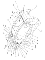
- FIG. 1 to 9 show a first example of an embodiment of the present invention.
- the feature of the present invention including the structure of the first example of the present embodiment, is the structure of the pad clip 15a and the return spring 16a in order to facilitate the assembly work of the pad clip 15a and the return spring 16a. It is in a devised point. Since the structure and operational effects of the other parts are almost the same as in the case of the first example of the conventional structure described above, the illustration and explanation of the equivalent parts are omitted or simplified. An explanation will be given focusing on the characteristic part of one example.
- the engagement recesses 20 and 20 formed in the turn-in side and the turn-out side engagement portions 7 and 8 at both ends in the circumferential direction of the support 3 are connected to the inner side and the outer side.
- the pads 9a and 9b can be displaced in the axial direction. I support it.
- the pad clips 15a and 15a are interposed between the engagement recesses 20 and 20 and the engagement protrusions 21 and 21, respectively.
- Each of these pad clips 15a, 15a is formed by bending and forming a metal plate having elasticity and corrosion resistance, like stainless spring steel, and a pair of leg portions 22 provided separately in the axial direction. , 22 are connected to each other by a connecting portion 23.
- Each of these leg portions 22 includes a positioning step portion 36, a torque receiving portion 37, and a bent portion 38 in a state of being continuous in the radial direction.
- the positioning step portion 36 is provided in a state of projecting toward the pads 9a and 9b in the circumferential direction at the radial intermediate portion of each leg portion 22, and has a substantially U-shaped cross section.
- the protrusions 39 formed in a part of the support 3 are engaged (the protrusions 39 are elastically fitted and clamped) to position the pad clips 15a in the radial direction.
- the torque receiving portion 37 is provided in a state of being bent at a substantially right angle from the radially inner side surface of the positioning step portion 36 to the radially inner side, and provided at the circumferential end of each of the pads 9a and 9b.
- Each engagement protrusion 21 is elastically pressed in the circumferential direction.
- the bent portion 38 is provided in a state of being bent from the radially inner end portion of the torque receiving portion 37 toward the pads 9a and 9b with respect to the circumferential direction. Elastically abuts the side.
- the rotor 1 in the axial direction is more than the pressure plates 10a, 10b constituting the pads 9a, 9b at both axial ends of the pad clips 15a, 15a.
- a pair of restraining portions 24, 24 are provided in a portion separated from (see FIG. 2).
- Each of the restraining portions 24, 24 extends from the torque receiving portions 37, 37 provided near the inner diameter of the leg portions 22, 22 in a direction away from each other with respect to the axial direction. It is formed by bending the pads 9a and 9b with respect to the direction.
- Each of the restraining portions 24, 24 having such a structure is configured so that a return spring 16a, which will be described later, can be attached to each pad clip 15a before the both pads 9a, 9b are assembled (with the pad clip 15a). It is provided to form an assembly with the return spring 16a), and supports each return spring 16a by supporting the elastic urging force (return force) of each return spring 16a. Further, at the portions near the outer diameters of the both leg portions 22 and 22, the protruding portions 25 are respectively provided in the portions that are bent substantially perpendicularly from the radially outer side surfaces of the positioning step portions 36 and 36 radially outward. , 25 are formed. Each of the projecting pieces 25, 25 is formed by forming a U-shaped cut at a portion near the outer diameter of each of the leg portions 22, 22, and bending the inside of the cut toward the caliper side (direction approaching each other). ing.
- the pad clips 15a and 15a having the above-described configuration are provided on the anchor side (the side where the brake torque is supported) and the non-anchor side portion of the disc brake, respectively.
- the leg portions 22, 22 constituting the respective pad clips 15a, 15a are the outer surfaces of the engaging projections 21, 21 provided at the end portions of the inner side and outer side pads 9a, 9b, respectively, It arrange
- the respective engagement protrusions 21 and 21 are elastically pressed toward the circumferential direction by the torque receiving portions 37 and 37 of the respective leg portions 22 and 22, and the pads 9a and 9b are supported by the support.
- the connecting portion 23 is positioned radially outward from the outer peripheral edge of the rotor 1, and connects the radially outer ends of the pair of leg portions 22, 22 to each other.
- each of the return springs 16a and 16a includes an inner side spring element 26a and an outer side spring element 26b, which are separate from each other.
- each of the spring elements 26a and 26b is a torsion coil spring formed by bending a spring steel wire such as stainless steel or piano wire, and a coil portion provided at an axially intermediate portion. 27, the base portions of the pair of arm portions 28a and 28b (the inner arm portion 28a and the outer arm portion 28b) are respectively continuous.
- the coil portion 27 has an inner diameter through which the projecting piece 25 formed on each pad clip 15a can be inserted, and its central axis is substantially the rotational direction of the rotor 1 ⁇ the circumferential direction of the pads 9a and 9b In the rotation direction (tangential direction) of the rotor 1 at the center, it is perpendicular to both the front and back surfaces of the leg 22 and is arranged in the left-right direction in FIG. Further, of the both arm portions 28a and 28b, the tip end portion of the inner arm portion 28a extending toward the rotor 1 in the axial direction is on the pad clip 15a side (anti-pads 9a and 9b side) in the circumferential direction. Each is formed as a locking portion 29 by bending.
- the distal end portions of the respective locking portions 29 and 29 are bent radially outward to form the locking pieces 40 and 40. Then, each of the release preventing pieces 40, 40 may be engaged with the back surface of the connecting portion 23 to prevent the return springs 16a from coming off the pad clip 15a.
- the outer arm portion 28b extending to the side opposite to the rotor 1 is substantially L-shaped in front view, and in order from the proximal end portion toward the distal end portion, the bending portion 30, the butting portion 31, It has an extension arm part 32 and a return part 33.
- the abutting portion 31 is a surface (inner side) facing the side surface of the rotor 1 among the restraining portions 24 and 24 constituting each pad clip 15a by the elastic restoring force of each spring element 26a (26b).
- it is linear and is provided so as to hang inward in the radial direction from the inner diameter side end of the bending portion 30. .
- the extending arm portion 32 is provided in a state of being bent at a substantially right angle from the radially inner end portion of the abutting portion 31 in a direction approaching the rotor 1, and substantially parallel to the central axis of the rotor 1. Is arranged. For this reason, in the case of the first example of the present embodiment, in order to prevent interference between the extending arm portion 32 and the circumferential edge portions of the pressure plates 10a and 10b, the pressure plates 10a, A recess 34 (34a) is formed at the circumferential edge of the engaging protrusions 21 and 21 of 10b. And the axial direction intermediate part of the said extension arm part 32 is penetrated in the axial direction inside each of these recessed parts 34 (34a).
- the axially intermediate portion of the extending arm portion 32 is inserted into the inside of the concave portion 34 that opens only in the circumferential direction as shown in FIG. ) As shown in FIG. 4B, the recess 34a is opened in the circumferential direction and the radial direction (inward).
- the length dimension in the axial direction of the extending arm portion 32 is regulated as follows. That is, the axial dimension of the extending arm portion 32 is made larger than the thickness dimension of the pads 9a and 9b in the axial direction, and the assembled state of the pads 9a and 9b (pads when not braked).
- the return portion 33 which will be described later, is connected to each of the engaging protruding pieces 21, 21.
- the length is set so as to be in contact with a surface (inner surface) facing the side surface of the rotor 1.
- the return portion 33 is separated from the pad clip 15a in the circumferential direction from the distal end portion (end portion on the rotor 1 side) of the extending arm portion 32 (on the side opposite to the locking portion 29). It is provided in a bent state and is in contact with the inner side surface of each of the engagement protrusions 21, 21. Further, a part of the return portion 33 (the base end portion in the illustrated example) is a virtual plane orthogonal to the central axis of the coil portion 27 ⁇ dot-dash line X shown in FIG. 7C ⁇ . , It is located on a virtual plane ⁇ dot-dash line Y shown in the figure ⁇ passing through the coil portion 27.
- the return portion 33 is positioned.
- the radial position of the return portion 33 substantially coincides with the radial position of the friction center of the linings 14a and 14b constituting the pads 9a and 9b.
- the wire diameter or shape can be made different between the spring elements 26a, 26b.
- the load (return force) of the outer side spring element 26b disposed on the outer side of the rotor 1 (giving an elastic biasing force to the outer side pad 9b).
- the load (returning force) of the inner spring element 26a disposed on the inner side (giving an elastic biasing force to the inner pad 9a).
- the load (return force) of the spring element provided on the anti-anchor side (inlet side, return side) should be larger than the load (return force) of the spring element provided on the anchor side (outlet side, return side). You can also.
- the pads 9a and 9b are attached to the support 3 when assembling the floating type disc brake.
- the return spring 16a is attached (preset) to the pad clip 15a. That is, an assembly of the pad clip 15a and the return spring 16a as shown in FIGS.
- the projecting piece 25 is placed inside the coil portion 27 in a state where both the arm portions 28a, 28b constituting the spring elements 26a, 26b are elastically deformed in a direction approaching each other. After the insertion, both the arm portions 28a, 28b are elastically returned (elastic deformation is released).
- the locking portion 29 provided at the distal end portion of the inner arm portion 28a is locked in a state where an elastic biasing force directed radially outward is applied to the inner peripheral edge portion of the connecting portion 23.
- the abutting portion 31 provided on the outer arm portion 28b is abutted against the inner surface of the restraining portion 24 in a state where an elastic urging force in a direction away from the rotor 1 with respect to the axial direction is applied.
- the arms 28a and 28b of the spring elements 26a and 26b are stretched between the inner peripheral edge of the connecting portion 23 constituting the pad clip 15a and the inner surfaces of the restraining portion 24.
- the inner peripheral surface of the coil portion 27 is pressed against the projecting piece 25 toward the rotor 1 side in the radial direction and in the axial direction.
- the spring elements 26a and 26b (return spring 16a) are attached to the pad clip 15a.
- the work of attaching the return spring 16a to the pad clip 15a in this manner can be performed at a disc brake assembly factory, or the parts supplier (pad clip 15a and return spring 16a are manufactured in advance). It can also be done in factories).
- the assembly process of the disk brake is performed in the assembly factory of the disc brake with the pad clip 15a and the return spring 16a.
- the assembly of the pad clip 15a and the return spring 16a is attached to the pad clip 15a.
- the pads 9 a and 9 b are assembled to the support 3.
- the elastic urging force is not yet applied to the two pads 9a and 9b from the return spring 16a in a state in which both the pads 9a and 9b are assembled.
- the pads 9a and 9b are slightly brought close to each other (for example, by a small amount of 1 mm or less), and elastic urging forces in directions away from each other are applied to the pads 9a and 9b. .
- the respective abutting portions 31 and 31 are slightly lifted from the respective restraining portions 24 and 24.
- the operation at the time of braking and releasing of the brake of the floating type disc brake of the first example of the present embodiment assembled as described above is as follows. First, at the time of braking, pressure oil is fed into a cylinder portion provided in a caliper (not shown), and the lining 14a of the inner pad 9a is pressed against the inner surface of the rotor 1 from the top to the bottom by the piston. Then, as a reaction of this pressing force, the caliper is displaced upward in FIG. 2 based on the sliding between the guide pins and the guide holes 5 and 5, and the claw portion is moved to the outer side (outside in the width direction of the vehicle). The lining 14 b of the pad 9 b (lower side in FIG.
- an elastic biasing force is applied to the pads 9a and 9a until the abutting portions 31 and 31 abut against the inner side surfaces of the restricting portions 24 and 24. At the same time, the elastic biasing force is not applied.
- the pad clips 15a when the pad clips 15a are assembled, the pad clips 15a and the return springs 16a are integrated (assemblies, sub-assemblies). ) And the assembly work becomes easy. That is, in the case of the first example of the present embodiment, as described above, the return springs 16a (spring elements 26a, 26b) are made elastic by the restraining portions 24, 24 provided on the pad clips 15a. By supporting the force, the return springs 16a can be supported on the pad clips 15a with sufficient support force corresponding to the elastic urging force.
- each of these pad clips 15a and each of the return springs 16a can be handled as an integral body (assembly), and the assembly work of each of the pad clips 15a and the return spring 16a can be performed at the same time.
- the assembling property can be improved and the assembling cost can be reduced.
- the work for mounting the return springs 16a to the pad clips 15a can be performed in a wide space where the work space is not limited, this work can be easily performed.
- an elastic urging force is not applied to both the pads 9a and 9b immediately after the both pads 9a and 9b are assembled (before the caliper is assembled yet).
- each of the restraining portions 24, 24 is engaged with the engaging protrusions 21, 21 of the pads 9a, 9b, thereby preventing the pads 9a, 9b from falling off the support 3. You can also. Therefore, the assembling work and the conveying work are not complicated. Further, since the pad clips 15a and the return springs 16a can be handled as a unit, the parts management cost can be reduced. The operation of mounting the return springs 16a to the pad clips 15a is performed in advance by a component supplier, and an assembly of the pad clips 15a and the return springs 16a is provided at a disc brake assembly factory.
- Management delivery management, box management, number management, inventory management, order management, storage location
- management delivery management, box management, number management, inventory management, order management, storage location
- the pad clips 15a and the return springs 16a are performed by the pad clips 15a and the return springs 16a.
- the number of man-hours for setup can be reduced, the erroneous assembling can be prevented, and the man-hours for assembling can also be reduced.
- each coil portion 27 is elastically pressed against each projecting piece 25, and therefore the posture (shape) of each spring element 26a, 26b. ) Can be stabilized. For this reason, it is possible to effectively prevent the return springs 16a (spring elements 26a and 26b) from dropping from the pad clips 15a and the mounting position from being displaced. Therefore, it is possible to improve the workability of the work of assembling the pad clips 15a and the return springs 16a to the support 3. Further, the return springs 16a make it easy to apply a desired return force to the pads 9a and 9b.
- each return spring 16a as a torsion coil spring provided with each coil portion 27, for example, the spring constant can be kept lower than when a wire spring having no coil portion is used. For this reason, even when the amount of wear of the linings 14a and 14a of both the pads 9a and 9b changes and the amount of movement of the pads 9a and 9a in the axial direction during braking increases, , 9b can be kept small (stabilized). That is, the elastic urging force applied to both the pads 9a and 9b can be made substantially constant until the linings 14a and 14b are almost worn out from the new state.
- each return portion 33 is placed on a virtual plane orthogonal to the central axis X of each coil portion 27. Since the coil portion 27 and a part of the return portion 33 (base end portion) are positioned on the virtual plane Y that passes therethrough, the positions in the circumferential direction of the coil portion 27 and the return portion 33 coincide with each other during braking. 27 is elastically deformed in the twisting direction (winding direction). Therefore, the elastic deformation (elastic urging force) of each of the coil portions 27 can be effectively used as a return force that separates the pads 9a and 9b from the rotor 1.
- the action direction of the return force by the return portions 33 is determined by the movement of the pads 9a and 9b. It is made to substantially coincide with the axial direction of the rotor 1 that is the direction. Therefore, the pads 9a and 9b can be efficiently separated from the rotor 1.
- the extending arm portions 32 are arranged substantially parallel to the central axis of the rotor 1, and the radial positions of the return portions 33 and 33 are set as follows. Since the pads 9a and 9b are made to coincide with the radial position of the friction center of the linings 14a and 14b constituting the pads 9a and 9b, both the pads 9a and 9b are inclined with respect to the rotor 1 in the brake release state. It is possible to effectively prevent any one of the inner and outer peripheral edges of the pads 9 a and 9 b from rubbing against the side surface of the rotor 1.
- each of the extending arm portions 32 is disposed substantially parallel to the central axis of the rotor 1, the pads 9a and 9b (linings 14a and 14b) are almost worn out from a new state.
- the trajectories of the return portions 33, 33 can be easily made parallel.
- the recessed part 34 (34a) is formed in the circumferential direction edge part of each said engagement protrusion piece 21 and 21, and each said extended arm part 32 is penetrated by the axial direction in these each recessed part 34 (34a). Therefore, the return portions 33, 33 can be connected to the engagement protrusions 21, without complicating the shapes of the return springs 16a (spring elements 26a, 26b) and the pad clips 15a.
- the structure which contacts the inner surface of 21 is realizable.
- each return spring 16a is composed of the inner side spring element 26a and the outer side spring element 26b.
- the wire diameter of the spring element 26b can be made larger than the wire diameter of the inner side spring element 26a.
- the elastic biasing force applied to the outer side pad 9b can be made larger than the elastic biasing force applied to the inner side pad 9a, and the wear of the lining 14b of the outer side pad 9b is likely to increase the wear amount.
- the amount can be effectively reduced.
- the thickness variation of the rotor 1 can be suppressed, and judder generation can be effectively prevented.
- the elastic biasing force applied to the pad 9b can be different from the elastic biasing force applied to the inner pad 9a.
- a concave groove may be formed on the inner side surface of the engaging protrusions 21 and 21, and the return portions 33 and 33 may be accommodated in the concave groove. According to such a configuration, even when the wear amount of the linings 14a and 14b increases (until they are completely worn out), it is possible to prevent the return portions 33 and 33 and the side surfaces of the rotor 1 from rubbing against each other. .
- FIG. 9 shows a second example of the embodiment of the present invention.
- the return spring 16b is integrally formed by bending a single wire.
- the return spring 16b includes the tip of the inner arm 28a of the inner spring element 26a and the tip of the inner arm 28a (see, for example, FIG. 4) of the outer spring 26b in the first example. It has a connected shape.
- the return spring 16b has a connecting arm portion 35 at the center in the axial direction provided so as to straddle the rotor 1 (see FIG. 2 and the like) and both end portions in the axial direction of the connecting arm portion 35.
- It comprises a pair of continuous coil portions 27a and 27a and outer arm portions 28b and 28b in which the respective base portions are connected to the respective coil portions 27a and 27a.
- the configurations of the coil portions 27a and the outer arm portions 28b are the same as in the case of the first example.
- the return spring 16b when the assembly work of the floating type disc brake is performed, the return spring 16b is attached to the pad clip 15a.
- the pad clip 15a is mounted using the restraining portions 24, 24 provided at both ends in the axial direction. That is, an assembly of the pad clip 15a and the return spring 16b (inner side spring element 26a, outer side spring element 26b) as shown in FIG. 9 is formed.
- the pad clip is formed on the inner side of each of the coil portions 27a and 27a in a state where the outer arm portions 28b and 28b constituting the return spring 16b are elastically deformed in a direction approaching each other.
- both outer arm portions 28b, 28b are elastically restored (elastic deformation is released).
- the pair of abutting portions 31, 31 constituting the return spring 16 b are elastically abutted against the inner surfaces of the restraining portions 24, 24 by the elastic restoring force of the return spring 16 b.
- the both abutting portions 31, 31 are stretched between the inner side surfaces of the respective restraining portions 24, 24.
- the return spring 16b is attached to the pad clip 15a.
- the assembly of the pad clip 15a and the return spring 16b is assembled to the support 3 (see FIG.
- the axially intermediate portion of the connecting arm portion 35 constituting the return spring 16b is provided.
- the protrusion 40a protrudes in a direction away from the caliper 2 (see FIGS. 27, 28, and 57) and radially outward.
- the come-off prevention piece 40a may be engaged with the back surface of the connecting portion 23 constituting the pad clip 15a to prevent the return spring 16b from coming off from the pad clip 15a.
- the locking piece 40a In the case of providing such a locking piece 40a, with the return spring 16b inclined with respect to the pad clip 15a, the locking piece 40a is inserted between the leg portions 22, 22, and thereafter The posture of the return spring 16b is returned, and the return spring 16b is assembled to the pad clip 15a.
- the return spring 16b is integrally formed, so that the first As in the case of one example, it is possible to reduce the number of parts and the number of assembling steps for the pad clip 15a as compared with the case where a separate structure is adopted. Further, by connecting the coil portions 27, 27 to each other by the connecting arm portion 35, a locking portion 29 for supporting a reaction force caused by pressing the return portions 33, 33 against the pads 9a, 9b. (See FIGS. 4 to 7 etc.) can be omitted. For this reason, assembly work (mounting work of the pad clip 15a and the return spring 16b) can be simplified. About another structure and an effect, it is the same as that of the case of the 1st example mentioned above.
- [Third example of embodiment] 10 to 18 show a third example of the embodiment of the present invention.
- the feature of the third example of the present embodiment is that the support structure of the return spring 16c for the pad clip 15b is different from the case of the first example of the above-described embodiment. Since the basic structure of the pad clip 15b and the return spring 16c is substantially the same as in the case of the first example, the description of the common parts is omitted or simplified. The explanation will focus on the features of the three examples.
- the connecting portion 23a is connected.
- a pair of locking notches 41 for locking a part of each return spring 16c (latching portion 29a described later) to the connecting portion 23a. , 41 are provided.
- Each of these locking notches 41, 41 is opened at the radially inner end edge of the connecting portion 23a, and is provided in a state of being separated from each other in the axial direction.
- each of the locking notches 41, 41 is about twice the wire diameter of each return spring 16c, and the width dimension in the axial direction is slightly larger than this wire diameter. Degree.
- a pair of locking holes that penetrate the connecting portion 23a in the circumferential direction (plate thickness direction) is formed in the connecting portion 23a. Locking portions 29a and 29a, which will be described later, can be locked in these locking holes.
- the outer portions of the leg portions 22a, 22a are closer to the outer diameter.
- a portion provided in a state of being bent radially outward from the radially outer surface of the positioning step portions 36, 36 is simply a flat surface. That is, in the case of the third example of the present embodiment, the protruding piece 25 (see FIGS. 1 and 7, etc.) is omitted as in the case of the first example and the second example.
- a pair of them are provided at both axial ends of the pad clips 15b.
- the restraining portions 24a and 24a are provided. Particularly in the case of the third example of the present embodiment, these restraining portions 24a, 24a are separated from each other in the axial direction from the torque receiving portions 37, 37 provided near the inner diameters of the respective leg portions 22a, 22a. In a state of extending in the direction, the tip end portion is formed by bending it toward the opposite side of the pad 9a, 9b in the circumferential direction.
- the restraining portions 24a and 24a are connected to the inner side surfaces of the torque receiving portions 37 and 37 (the circumferential end surfaces of the engagement projecting pieces 21 and 21 and the circumferential surface thereof). It is provided on the side opposite to the pad 9a, 9b in the circumferential direction (offset) from the surface facing the direction).
- each of the return springs 16c and 16c is composed of an inner side spring element 26c and an outer side spring element 26d, which are separate from each other.
- each of the spring elements 26c and 26d is a torsion coil spring formed by bending a spring steel wire such as stainless steel or piano wire, and the axial direction of the portion near the radially outer end is formed.
- a base portion of a pair of arm portions 28c and 28d is connected to the coil portion 27b provided in the intermediate portion.
- the diameter of the coil portion 27b is set to the coil portion 27 constituting the return spring 16a (16b) used in the first and second examples of the above-described embodiment. It is larger than the diameter of (27a).
- the radially inner end portions of the coil portions 27b are provided at the radial intermediate portions of the leg portions 22a.
- the positioning step portions 36 are brought into contact with the radially outer side surfaces.
- the winding number of each said coil part 27b is not ask
- One volume may be used as shown in FIG.
- the number of turns of the coil portion 27b may be different between the inner spring element 26c and the outer spring element 26d.
- the number of turns of the coil part 27b constituting the outer side spring element 26d is made larger than the number of turns of the coil part 27b constituting the inner side spring element 26c, and the outer side spring element 26d is constituted.
- the wire is made thicker than the wire constituting the inner spring element 26c, and the return force applied to the outer pad 9b is made larger than the return force applied to the inner pad 9a without increasing the spring constant. .
- the tip end portion of the inner arm portion 28c extending toward the rotor 1 with respect to the axial direction is the pad clip 15b side (anti-pad 9a, 9b side) with respect to the circumferential direction. )
- locking part 29a is each latched with respect to each latching notch 41 formed in the said connection part 23a without rattling. Specifically, each of the locking portions 29a is locked to each locking notch 41 in a state where an elastic biasing force directed radially outward is applied, and the displacement in the axial direction is disabled. is doing.
- each locking portion 29a is bent outward in the radial direction, a locking member 40b is formed at that portion.
- Each of the anti-slip pieces 40b is engaged with the back surface of the connecting portion 23a to prevent the return springs 16c from coming off from the pad clips 15b.
- the outer arm portion 28d extending to the side opposite to the rotor 1 is substantially U-shaped in a front view, and in order from the proximal end portion toward the distal end portion, the bending portion 30a, the outer diameter side bent portion 42, and the protrusion. It has the contact part 31a, the inner diameter side bending part 43, the extension arm part 32a, and the return part 33a.
- the curved portion 30a has a quarter arc shape, and is bent in a radially inward direction toward the distal end side.
- the outer-diameter side bent portion 42 is provided in a state of being bent at a substantially right angle from the inner-diameter side end portion of the curved portion 30a toward the counter pad 9a, 9b side in the circumferential direction.
- the abutting portion 31a is a surface (inner side) facing the side surface of the rotor 1 among the restraining portions 24a and 24a constituting each pad clip 15b by the elastic restoring force of each spring element 26c (26d). It is a portion that is abutted against the side surface, and is provided in a straight line and hangs inward in the radial direction from the inner diameter side end of the outer diameter side bent portion 42.
- the inner diameter side bent portion 43 is provided in a state of being bent from the inner diameter side end portion of the abutting portion 31a to the pads 9a and 9b in the circumferential direction and to the rotor 1 side in the axial direction.
- the abutting portion 31a can be arranged in the circumferential direction rather than the inner side surfaces (surfaces facing the circumferential end surfaces of the engaging projection pieces 21 and 21 in the circumferential direction) of the torque receiving portions 37 and 37. It is provided on the side opposite to the pads 9a and 9b (offset).
- the extending arm portion 32 a is linear and extends from the tip end portion of the inner diameter side bent portion 43 in a direction approaching the rotor 1, and is disposed substantially parallel to the central axis of the rotor 1. .
- a recess 34 (34a) is formed at the circumferential edge of the engaging protrusions 21 and 21 of 10b.
- the axial direction intermediate part of the said extension arm part 32a is penetrated by the axial direction inside each recessed part 34 (34a).
- the return portion 33a is provided in a state of being bent from the tip end portion of the extending arm portion 32a in a direction away from each pad clip 15a in the circumferential direction (on the side opposite to the locking portion 29a).
- the engagement protrusions 21 and 21 are in contact with the inner side surfaces.
- the radial position of the return portion 33a substantially coincides with the radial position of the friction center of the linings 14a and 14b constituting the pads 9a and 9b.
- the pads 9a and 9b are attached to the support 3 when assembling the floating type disc brake.
- the return spring 16c is attached (preset) to the pad clip 15b. That is, an assembly of the pad clip 15b and the return spring 16c (inner side spring element 26c, outer side spring element 26d) as shown in FIGS.
- the locking portion 29a provided at the tip of the inner arm portion 28c constituting each of the spring elements 26c, 26d is inserted into the locking notch 41 formed in the connecting portion 23a (engagement).
- the outer arm portion 28d After the outer arm portion 28d is elastically deformed in the direction approaching the inner arm portion 28c, the outer arm portion 28d is elastically restored (elastic deformation is released).
- the locking portion 29a is locked to the locking notch 41 in a state in which an elastic biasing force directed outward in the radial direction is applied, and the displacement in the axial direction is locked in an impossible manner.
- the abutting portion 31a is abutted against the inner surface of the restraining portion 24a in a state where an elastic biasing force in a direction away from the rotor 1 with respect to the axial direction is applied.
- the spring elements 26c and 26d (return spring 16c) are positioned with respect to the pad clip 15b in the radial direction and the axial direction.
- the assembly of the pad clip 15b and the return spring 16c is configured).
- the anti-disengagement piece 40b and the abutting portion 31a of the spring elements 26c and 26d are placed on the back side of the pad clip 15b, and the remaining portion is placed on the front. Therefore, the spring elements 26c and 26d can be positioned with respect to the pad clip 15b in the circumferential direction.
- the assembly of the pad clip 15b and the return spring 16c is assembled to the support 3 (see FIGS. 13 to 15), and thereafter As shown in FIGS. 10 to 12, the pads 9 a and 9 b are assembled to the support 3. In addition, an elastic urging force is not yet applied from the return spring 16c to the pads 9a and 9b in a state where the pads 9a and 9b are assembled to the support 3 in this way.
- each said restraint part 24a, 24a and each said abutting part 31a, 31a are made from the inner surface (surface facing the circumferential direction end surface of the engagement protrusions 21 and 21) of each said torque receiving part 37 and 37. Since the pads 9a and 9b are offset in the circumferential direction, both the pads 9a and 9b can be assembled by simply translating both the pads 9a and 9b in the axial direction. For this reason, the assembling work is easy and the working efficiency can be improved. Other configurations and operational effects are the same as in the case of the first example.
- [Fourth Example of Embodiment] 19 to 23 show a fourth example of the embodiment of the present invention.
- the feature of the fourth example of the present embodiment is that the support structure of the return spring 16d for the pad clip 15c is different from the case of the first to third examples of the above-described embodiment. Since the basic structure of the pad clip 15c and the return spring 16d is substantially the same as in the case of the first example, the description of the common parts will be omitted or simplified. The explanation will focus on the features of the four examples.
- the radially outer ends of the pair of leg portions 22b, 22b provided with the pad clips 15c spaced apart in the axial direction are connected by the connecting portion 23b.
- the turn-back portions 44 for supporting the coil portions 27c and 27c constituting the return spring 16d at the radially outer ends of the leg portions 22b and 22b, 44 is provided.
- each of the folded portions 44, 44 is bent at a substantially right angle from the radially outer surface of the positioning step portions 36, 36 to the radially outer side, and the radially intermediate portion of the pad 9a, It is formed by folding back into a substantially U shape on the 9b side.
- the dimension in the radial direction between the radially inner side surface of the folded portions 44, 44 and the radially outer side surface of the positioning step portions 36, 36 is set to be slightly larger than the diameter of each coil portion 27c. Yes.
- the distance between the opposite side surfaces of each folded portion 44, 44 in the circumferential direction is slightly larger than the thickness dimension of each coil portion 27c.
- a pair of restraining portions 24b and 24b are provided at both axial ends of each pad clip 15c.
- the restraining portions 24b and 24b are arranged on the radially outer side surfaces of the positioning step portions 36 and 36 and the radially inner end portions of the folded portions 44 and 44, respectively. In this state, the tip end portion (the end portion on the anti-rotor side) is extended so as to be bent toward the anti-pads 9a and 9b side in the circumferential direction.
- each of the restraining portions 24b and 24b is the inner surface of the torque receiving portions 37 and 37 (the surface facing the circumferential end surface of the engaging protrusions 21 and 21). ) With respect to the circumferential direction than the pad 9a, 9b.
- a part of the return spring 16d (spring element 26e, 26a, 36b) is formed on the radially outer surface of the positioning step portions 36, 36 constituting the legs 22b, 22b.
- Locking holes 45, 45 for locking the inner arm portion 28e of 26f) are formed so as to penetrate in the radial direction.
- each return spring 16d, 16d is composed of an inner spring element 26e and an outer spring element 26f, which are separate from each other.
- each of these spring elements 26e and 26f is a torsion coil spring formed by bending a spring steel wire such as stainless steel or piano wire, and the axial direction of the portion near the radially outer end.
- the base portions of the pair of arm portions 28e and 28f are respectively connected to the coil portion 27c provided in the intermediate portion.
- the coil portions 27c are not rattled at the portions surrounded by the radially outer surfaces of the abutting step portions 36 and the folded portions 44. Incorporated.
- the tip end portion of the inner arm portion 28e extending toward the rotor 1 side in the axial direction and radially inward is bent toward the rotor 1 side in the axial direction.
- the locking portions 46 are used.
- the locking portions 46 are locked in the locking holes 45 formed in the positioning step portion 36 from the outside in the radial direction. Further, in this state, the front end portion of each inner arm portion 28e is abutted against the opening portion of each locking hole 45 in a state where an elastic biasing force directed toward the rotor 1 in the axial direction is applied. ing.
- the outer arm portion 28f extending to the side opposite to the rotor 1 is substantially L-shaped when viewed from the front, and in order from the proximal end portion toward the distal end portion, the proximal end portion 47, the bent portion 48, and the extended arm. It has the part 32b and the return part 33b.
- the base end portion 47 has a radially intermediate portion as an abutting portion 31b and is linear.
- the abutting portion 31b is formed by the elastic elements of the spring elements 26e and 26f (coil portions 27c and 27c), among the restraining portions 24b and 24b constituting the pad clips 15c.
- the bent portion 48 is provided in a state bent from the inner diameter side end portion of the base end portion 47 to the pads 9a and 9b side in the circumferential direction and to the rotor 1 side in the axial direction.
- the extending arm portion 32 b is linear and extends in a direction approaching the rotor 1 from the distal end portion of the bent portion 48, and is disposed substantially parallel to the central axis of the rotor 1.
- the pressure plates 10a, 10b in order to prevent interference between the extending arm portion 32b and the circumferential edges of the pressure plates 10a, 10b, the pressure plates 10a, 10b.
- a recess 34 (34a) is formed at the circumferential edge of the engaging protrusions 21 and 21.
- the axial direction intermediate part of the said extension arm part 32b is penetrated by the axial direction inside each recessed part 34 (34a).
- the return portion 33b is provided in a state of being bent from the distal end portion of the extending arm portion 32b in a direction away from the pad clip 15c with respect to the circumferential direction. It is in contact with the inner surface.
- the radial position of the return portion 33b substantially coincides with the radial position of the friction center of the linings 14a and 14b constituting the pads 9a and 9b.
- the pads 9a and 9b are attached to the support 3 when assembling the floating type disc brake.
- the return spring 16d is attached (preset) to the pad clip 15c. That is, an assembly of the pad clip 15c and the return spring 16d (inner side spring element 26e, outer side spring element 26f) as shown in FIG. 22 is formed.
- the coil portion 27 c constituting each of the spring elements 26 e and 26 f is incorporated in a portion surrounded by the radially outer side surface of each positioning step portion 36 and each folded portion 44.
- the outer arm portion 28f is elastically deformed in a direction approaching the inner arm portion 28e, and then the outer arm portion 28f is elastically returned (elastic deformation is released).
- the portion closer to the tip of the inner arm portion 28e is abutted against the opening portion of each locking hole 45 in a state where an elastic biasing force directed toward the rotor 1 with respect to the axial direction is applied, and
- the abutting portion 31b is abutted against the side edge portion of the restraining portion 24b in a state where an elastic urging force is applied in a direction away from the rotor 1 in the axial direction and radially outward.
- the spring elements 26e and 26f (return spring 16d) are positioned with respect to the pad clip 15c in the radial direction, the circumferential direction, and the axial direction. (The assembly of the pad clip 15c and the return spring 16d is configured).
- the assembly of the pad clip 15c and the return spring 16d is assembled to the support 3, and then shown in FIGS.
- the pads 9 a and 9 b are assembled to the support 3.
- both the pads 9a and 9b in the state in which the both pads 9a and 9b are assembled to the support 3 are still elastic from the return spring 16d. No biasing power is granted.
- each of the pad clips 15c is assembled, each of the pad clips 15c and each of the return springs 16d can be handled as an integrated body (assembly, subassembly). For this reason, the assembling work of each pad clip 15c and the return spring 16d can be performed simultaneously, and the assembling work becomes easy. As a result, the assemblability can be improved and the assembling cost can be reduced.
- both the pads 9a and 9b are removed from the support 3. There is no need to take care not to slip out in the axial direction. Therefore, the assembly work and the transport work are not complicated from this side. Further, since the pad clips 15c and the return springs 16d can be handled as an integrated body (assembly), the parts management cost can be reduced.
- the axial direction, the circumferential direction, and the radial direction of each of the spring elements 26e, 26f with the return springs 16d attached to the pad clips 15c Therefore, the posture (shape) of each of the spring elements 26e and 26f can be stabilized. Accordingly, it is possible to effectively prevent the return springs 16d (spring elements 26e and 26f) from falling off the pad clips 15c and the mounting positions from being displaced. As a result, the workability of assembling the pad clips 15c and the return springs 16d to the support 3 can be improved.
- the restraining portions 24c and 24c are provided on the radially outer surface portions of the positioning step portions 36 and 36.
- the material cost can be kept low. That is, in the case of the pad clip 15 (15a, 15b) in the first to third examples, the restraining portions 24, 24a are provided in a state of extending from the torque receiving portion 37 in a direction away from each other in the axial direction.
- the extension amount is larger than that in the fourth example of the present embodiment. For this reason, the width dimension of the pad clip 15 (15a, 15b) at the time of expansion
- the pad clip 15c of the fourth example of the present embodiment since the width dimension at the time of development can be suppressed small, the material cost can be suppressed.
- Other configurations and operational effects are the same as those in the first and third examples.
- [Fifth Example of Embodiment] 24 to 26 show a fifth example of the embodiment of the present invention.
- the feature of the fifth example of the present embodiment is that the shape of the pad clip 15c of the fourth example of the embodiment described above is devised. That is, the pad clip 15d of the fifth example of the present embodiment has a shape such that the connecting portion 23b is omitted from the pad clip 15c of the fourth example, and each includes leg portions 22b and 22b. It is composed of an inner side clip element 49a and an outer side clip element 49b.
- the inner side clip element 49a and The inner side spring element 26e and the outer side spring element 26f constituting the return spring 16d are mounted (preset) to the outer side clip element 49b, respectively. That is, an assembly of the pad clip 15d (inner side clip element 49a, outer side clip element 49b) and the return spring 16d (inner side spring element 26e, outer side spring element 26f) is formed.
- the inner side assembly 50a constituted by the inner side clip element 49a and the inner side spring element 26e, the outer side clip element 49b and the outer side clip element 26f.
- the constructed outer side assembly 50b is assembled to the support 3 separately (or simultaneously).
- the pad clip 15d (inner side, The outer side clip elements 49a and 49b) can be configured to be small and light. For this reason, the handleability of each pad clip 15d can be improved, and the assembling workability of each pad clip 15d can be improved. Further, the material cost for forming each pad clip 15d can be reduced. About another structure and an effect, it is the same as that of the case of the 1st example and 4th example of embodiment mentioned above.
- FIG. 27 to 37 show a sixth example of the embodiment of the present invention.
- the pair of return springs 16e and 16e provided on the turn-in side and the turn-out side are respectively composed of an inner side spring element 26g and an outer side spring element 26h.
- each of the pair of pad clips 15e, 15e attached to the both ends of the support 3 at the turn-in side and the turn-out side, respectively has a substantially U-shaped cross section at the radial intermediate portion of each leg 22c, 22c.
- Certain positioning step portions 36a and 36a are provided in a state of projecting toward the inner side and outer side pads 9a and 9b in the circumferential direction.
- Each of the positioning step portions 36a and 36a is a holding portion provided in a state where the outer side in the radial direction is opened in the support 3 in order to hold a part of the support 3, that is, the pads 9a and 9b. It is elastically fitted to the convex portions 39a, 39a formed at both ends in the circumferential direction of the inner surface. Then, the projections 39a and 39a are clamped from both sides in the radial direction by the positioning step portions 36a and 36a, thereby positioning the pad clips 15e and 15e in the radial direction.
- the projections 39a and 39a are held across the full width in the axial direction by the positioning step portions 36a and 36a. That is, in the case of the fourth to fifth examples of the above-described embodiment, the positioning step portion 36 and the convex portion 39 (see FIG. 24) are folded back and formed only on a part of the positioning step portion 36 in the width direction. 51 (see FIG. 24 and FIG. 26C) only. For this reason, the support rigidity of the pad clips 15c and 15d with respect to the support 3 may not necessarily be sufficient. In particular, as in the fifth example of the embodiment described in FIGS.
- the protruding amount of each positioning step portion 36a, 36a in the circumferential direction is set to be larger than the protruding amount of each protruding portion 39a, 39a,
- a gap 52 (see FIG. 35) is interposed between the inner surfaces of the distal end portions of the positioning step portions 36a and 36a and the distal end surfaces of the convex portions 39a and 39a.
- the return springs 16e and 16e are formed in locking holes 45a and 45a formed at portions protruding from the tip surfaces of the convex portions 39a and 39a at the tip portions of the positioning step portions 36a and 36a.
- the engaging portions 46a and 46a provided at one end portions of the inner side spring element 26g and the outer side spring element 26h are inserted.
- the installation positions of the respective locking portions 46a, 46a are brought closer to the circumferential central portion of the support 3, and the springs are arranged in the circumferential direction.
- Positions at which the return portions 33c, 33c provided at the other ends of the elements 26g, 26h contact the pressure plates 10a, 10b of the inner side and outer side pads 9a, 9b, and the positions of the respective locking portions 46a, 46a Are almost the same. That is, the return portions 33c and 33c and the pressure plates 10a and 10b have a certain length range with respect to the circumferential direction (the length between the alternate long and short dash line ⁇ shown in FIGS. 34 and 35). In the range).
- each of the locking portions 46a, 46a (the chain line ⁇ shown in FIGS. 34 and 35) is within this length range. That is, as shown in FIGS. 34 and 35, the alternate long and short dash line ⁇ is located between the alternate long and short dash line ⁇ and the alternate long and short dash line ⁇ . Accordingly, with the assembly of the pads 9a and 9b to the support 3, the return portions 33c and 33c and the locking portions 46a and 46a provided with the spring elements 26g and 26h at the both ends are provided.
- the return portions 33c and 33c press the pressure plates 10a and 10b, and the locking portions 46a and 46a connect the pad clip 15e.
- the pressing directions are almost axial directions and opposite to each other.
- the elastic urging force of the spring elements 26g and 26h can be efficiently transmitted to the pads 9a and 9b as a force in a direction in which the pads 9a and 9b are separated from each other.
- both the pads 9a and 9b can be reliably separated without using a spring element having a particularly large elastic urging force by using, for example, a thick wire as the spring elements 26g and 26h. .
- the processing costs of the spring elements 26g and 26h be reduced, but also the assembly work of the spring elements 26g and 26h can be facilitated.
- the folded portions 53 and 53 having a substantially U-shaped cross section that opens radially outward at both ends in the axial direction and at the radially outer end of the pad clip 15e. Is forming.
- the coil portions 27c and 27c constituting the spring elements 26g and 26h are hooked on the folded portions 53 and 53 (the folded portion 53 is inserted inside the coil portion 27c).
- the direction of insertion of the locking portions 46a, 46a into the locking holes 45a, 45a and the direction of the folding portions 53, 53 are described above.
- returning part 53, 53 is made smaller than the width dimension of each said coil part 27c, 27c by providing a bending part in the front-end
- a hook-shaped restraint that opens downward at the radially outer ends (shoulders of the pad clip 15e) at both ends of the pad clip 15e in the axial direction.
- Portions 24c and 24c are provided.
- Each of the restraining portions 24c and 24c is bent in a direction in which the tip end portion (the inner half portion in the radial direction, the lower half portion in FIGS. 30 to 33) approaches the pads 9a and 9b in the circumferential direction.
- the portions between the coil portions 27c and 27c and the return portions 33c and 33c are arranged in order from the side of the coil portions 27c and 27c.
- a proximal-side straight portion 54 provided with an abutting portion 59 at the end-side portion, a bending portion 30b, and an extending arm portion 32c are provided.
- the return springs 16e spring elements 26g and 26h
- the abutting portions 59, 59 of the spring elements 26g, 26h are abutted against the restraining portions 24c, 24c.
- the restraining portions 24c and 24c With the abutting portions 59 and 59 engaged with the restraining portions 24c and 24c, the restraining portions 24c and 24c have the return portions 33c and 33c in the state shown in FIGS. 31 and 37, respectively.
- the restraining portions 24c and 24c hold the abutting portions 59 and 59 at the same time as preventing displacement in the direction away from each other.
- the portions of the spring elements 26g and 26h excluding the return portions 33c and 33c are prevented from projecting toward the center of the support 3 in the circumferential direction of the rotor.
- the spring elements 26g and 26h do not interfere with each other when the pads 9a and 9b are assembled to the support 3 while being translated in the axial direction, and the assembling work can be easily performed.
- the pad clips 15e of the pad clips 15e are formed at the circumferential ends (engaging protrusions 21) of the both pads 9a and 9b. What is necessary is just to push this circumferential direction edge part into the torque receiving part 37 of this pad clip 15e, elastically deforming the bending part 38 in the direction to crush.
- the circumferential ends of the pressure plates 10a and 10b of the pads 9a and 9b are moved from the state shown in FIG. 31 to the state shown in FIG. It is incorporated into the support 3 while being elastically deformed from a solid line state to a two-dot chain line state.
- the shape of the return spring 16e shown in FIGS. 29 and 30 is shown in a state where the pads 9a and 9b (and the caliper 2) are elastically deformed to the state where they are assembled to the support 3.
- the pads 9a and 9b (and the caliper 2) are elastically deformed to the state where they are assembled to the support 3.
- FIGS. 38 to 43 show a seventh example of the embodiment.
- the shape of the return spring 16e (inner side spring element 26g, outer side spring element 26h) shown in FIGS. 38 to 43 is such that the pads 9a and 9b (see FIGS. 1 to 3 etc.) are assembled to the support 3. It is shown in a state of being elastically deformed.
- a pad clip 15f having a shape in which the connecting portion 23c is omitted from the pad clip 15e of the sixth example of the above-described embodiment is used.
- the pad clip 15f is composed of an inner side clip element 49c and an outer side clip element 49d, which are composed of legs 22c and 22c, which are separate from each other.
- the inner pads 9a, 9b are assembled to the support 3 as shown in FIG.
- An inner side spring element 26g and an outer side spring element 26h constituting the return spring 16e are attached (preset) to the side clip element 49c and the outer side clip element 49d, respectively. That is, the pad clip 15f (inner side clip element 49c, outer side clip element 49d) and return spring 16e (inner side spring element 26g, outer side spring element 26h) constitute an assembly.
- An inner side assembly 50c constituted by the inner side clip element 49c and the inner side spring element 26g, and an outer side assembly 50d constituted by the outer side clip element 49d and the outer side spring element 26h. Are assembled to the support 3 separately (or simultaneously).
- the pad clip 15f (inner side, The outer side clip elements 49c and 49d) can be made compact and lightweight. For this reason, the handling property of each pad clip 15f can be improved, and the assembling workability of each pad clip 15f can be improved. Further, the material cost for forming each pad clip 15f can be reduced. About another structure and an effect, it is the same as that of the case of the 1st example and 6th example of embodiment mentioned above.
- FIGS. 44 to 49 show an eighth example of the embodiment.
- the shape of the return spring 16e (inner side spring element 26g, outer side spring element 26h) shown in FIGS. 44 to 49 is also such that the pads 9a and 9b (see FIGS. 1 to 3 etc.) are assembled to the support 3. It is shown in a state of being elastically deformed.
- the pad clip 15g of the eighth example of the present embodiment the restraining portions 24c and 24c of the pad clip 15e of the sixth example of the above-described embodiment are restrained by the restraints of the pad clip 15a of the first example of the above-described embodiment. The parts 24 and 24 are replaced.
- the restraining portions 24, 24 of the pad clip 15g of the eighth example of the present embodiment extend from the torque receiving portions 37, 37 provided near the inner diameter of the leg portions 22d, 22d in a direction away from each other in the axial direction.
- the intermediate part is formed by bending the pad 9a, 9b in the circumferential direction.
- [Ninth Embodiment] 50 to 56 show a ninth example of the embodiment.
- the shape of the return spring 16e (inner side spring element 26g, outer side spring element 26h) shown in FIGS. 50 to 56 is also the state in which the pads 9a and 9b (see FIGS. 1 to 3 etc.) are assembled to the support 3. It is shown in a state of being elastically deformed.
- a pad clip 15h having a shape such that the connecting portion 23c is omitted from the pad clip 15g of the eighth example of the above-described embodiment is used.
- the pad clip 15h is composed of an inner side clip element 49e and an outer side clip element 49f, each of which is composed of leg portions 22d and 22d.
- the inner side of the pad 9a, 9b before being assembled to the support 3 is shown.
- the inner side spring element 26g and the outer side spring element 26h constituting the return spring 16e are mounted (preset) to the clip element 49e and the outer side clip element 49f, respectively. That is, an assembly of the pad clip 15h (inner side clip element 49e, outer side clip element 49f) and the return spring 16e (inner side spring element 26g, outer side spring element 26h) is formed.
- An inner side assembly 50e constituted by the inner side clip element 49e and the inner side spring element 26g, and an outer side assembly 50f constituted by the outer side clip element 49f and the outer side spring element 26h. Are assembled to the support 3 separately (or simultaneously).
- the pad clip 15h (inner side, The outer side clip elements 49e, 49f) can be configured to be small and light. For this reason, the handling property of each pad clip 15h can be improved, and the assembling workability of each pad clip 15h can be improved. Further, the material cost for forming each pad clip 15h can be reduced. About another structure and an effect, it is the same as that of the case of the 1st example and 8th example of embodiment mentioned above.
- Japanese Patent Application No. 2010-090770 Japanese patent application filed on October 6, 2010
- Japanese Patent Application No. 2010-226785 Japanese patent application filed on March 14, 2011. This is based on a Japanese patent application (Japanese Patent Application No. 2011-055045), the contents of which are incorporated herein by reference.
- the legs constituting the pad clip are arranged between the support and the inner side and outer side pads, respectively, and when releasing the brake, these pads are attached with elasticity of the return spring.
- the present invention is not limited to such a configuration. That is, it is also possible to dispose the leg portion constituting the pad clip only between the support and one pad, and to separate only this one pad from the rotor using the elastic biasing force of the return spring. In the case of adopting such a configuration, for example, only an assembly including an inner side clip element (or outer side clip element) and an inner side spring element (or outer side spring element) is assembled to the support.
- each element can be freely selected regardless of the inner side, outer side, anchor side, or anti-anchor side.
- assemblies having different configurations can be assembled as assemblies assembled on the inner side, the outer side, the anchor side, and the anti-anchor side.
Landscapes
- Engineering & Computer Science (AREA)
- General Engineering & Computer Science (AREA)
- Mechanical Engineering (AREA)
- Braking Arrangements (AREA)
Priority Applications (3)
| Application Number | Priority Date | Filing Date | Title |
|---|---|---|---|
| US13/638,711 US8869950B2 (en) | 2010-04-09 | 2011-04-08 | Floating disc brake, method of assembling same, and assemblies consisting of pad clips and return springs |
| EP11766025.8A EP2557330B1 (en) | 2010-04-09 | 2011-04-08 | Floating disc brake, method of assembling same, and assemblies consisting of pad clips and return springs |
| CN201180018218.4A CN102834638B (zh) | 2010-04-09 | 2011-04-08 | 浮盘式制动器、组装浮盘式制动器的方法,和由衬垫夹和复位弹簧组成的组件 |
Applications Claiming Priority (6)
| Application Number | Priority Date | Filing Date | Title |
|---|---|---|---|
| JP2010090770 | 2010-04-09 | ||
| JP2010-090770 | 2010-04-09 | ||
| JP2010226785 | 2010-10-06 | ||
| JP2010-226785 | 2010-10-06 | ||
| JP2011-055045 | 2011-03-14 | ||
| JP2011055045A JP5292425B2 (ja) | 2010-04-09 | 2011-03-14 | フローティング型ディスクブレーキとその組立方法並びにパッドクリップとリターンスプリングとの組立体 |
Publications (1)
| Publication Number | Publication Date |
|---|---|
| WO2011126125A1 true WO2011126125A1 (ja) | 2011-10-13 |
Family
ID=44763059
Family Applications (1)
| Application Number | Title | Priority Date | Filing Date |
|---|---|---|---|
| PCT/JP2011/058949 WO2011126125A1 (ja) | 2010-04-09 | 2011-04-08 | フローティング型ディスクブレーキとその組立方法並びにパッドクリップとリターンスプリングとの組立体 |
Country Status (5)
| Country | Link |
|---|---|
| US (1) | US8869950B2 (fi) |
| EP (1) | EP2557330B1 (fi) |
| JP (1) | JP5292425B2 (fi) |
| CN (1) | CN102834638B (fi) |
| WO (1) | WO2011126125A1 (fi) |
Cited By (6)
| Publication number | Priority date | Publication date | Assignee | Title |
|---|---|---|---|---|
| US9261152B2 (en) | 2013-05-14 | 2016-02-16 | Akebono Brake Corporation | Coiled spreader spring |
| EP2791537B1 (fr) | 2011-12-15 | 2016-06-29 | Robert Bosch GmbH | Organe de guidage a verrou d'un patin de frein a disque et frein a disque equipe de tels organes de guidage |
| EP2791535B1 (fr) | 2011-12-15 | 2016-07-20 | Robert Bosch GmbH | Organe de guidage a ressort d'un patin de frein a disque et frein a disque equipe de tels organes de guidage |
| CN104583635B (zh) * | 2012-08-23 | 2017-05-17 | 卢卡斯汽车股份有限公司 | 回复弹簧以及包括可塑性变形的回复弹簧的机动车用盘式制动器 |
| CN107740826A (zh) * | 2017-11-21 | 2018-02-27 | 重庆比速汽车有限公司 | 新型浮钳盘式制动器 |
| CN113692500A (zh) * | 2019-04-17 | 2021-11-23 | 大陆-特韦斯贸易合伙股份公司及两合公司 | 具有摩擦衬片复位弹簧的机动车辆盘式制动器衬片 |
Families Citing this family (31)
| Publication number | Priority date | Publication date | Assignee | Title |
|---|---|---|---|---|
| JP2014516143A (ja) * | 2011-06-09 | 2014-07-07 | ベイジンウェスト・インダストリーズ・カンパニー・リミテッド | 揺動パッド式ブレーキキャリパー |
| DE102012010932A1 (de) * | 2012-06-01 | 2013-12-05 | Lucas Automotive Gmbh | Führungsmittel für eine Bremsbelanganordnung |
| US20140305753A1 (en) * | 2013-04-12 | 2014-10-16 | Akebono Brake Corporation | Pad retraction clip |
| JP6134926B2 (ja) * | 2013-06-28 | 2017-05-31 | 日立オートモティブシステムズ株式会社 | ディスクブレーキ |
| US9267559B2 (en) * | 2013-09-25 | 2016-02-23 | Akebono Brake Industry Co., Ltd | Dampening clip |
| JP6434214B2 (ja) * | 2014-02-06 | 2018-12-05 | 株式会社小糸製作所 | 車両用灯具 |
| KR101628600B1 (ko) * | 2015-01-06 | 2016-06-08 | 현대자동차주식회사 | 드래그가 축소되는 브레이크 캘리퍼용 패드 라이너 |
| WO2016149068A1 (en) * | 2015-03-13 | 2016-09-22 | Kelsey-Hayes Company | Anchor bracket for use in a disc brake assembly, disc brake assembly including such an anchor bracket and method for producing such an anchor bracket |
| DE102016104970A1 (de) * | 2015-06-15 | 2016-12-15 | Knorr-Bremse Systeme für Nutzfahrzeuge GmbH | Scheibenbremse für ein Nutzfahrzeug und Bremsbelagsatz |
| DE112016003042T5 (de) * | 2015-07-03 | 2018-03-22 | Hitachi Automotive Systems, Ltd. | Scheibenbremse und Verfahren zur Herstellung der Scheibenbremse |
| DE102015226344A1 (de) | 2015-12-21 | 2017-06-22 | Knorr-Bremse Systeme für Schienenfahrzeuge GmbH | Bremssteuerung für Schienenfahrzeuge mit adaptiver Belag-Kennlinie |
| WO2018017966A1 (en) * | 2016-07-21 | 2018-01-25 | Preferred Tool & Die, Inc. | Caliper hardware providing separation between pad and rotor |
| DE102016117777A1 (de) * | 2016-09-21 | 2018-03-22 | Knorr-Bremse Systeme für Nutzfahrzeuge GmbH | Scheibenbremse für ein Nutzfahrzeug und Bremsbelagsatz |
| JP6982493B2 (ja) | 2017-12-28 | 2021-12-17 | 曙ブレーキ工業株式会社 | パッドクリップ、パッドクリップと戻しばねとの組立体、及びフローティング型ディスクブレーキ |
| KR102466679B1 (ko) * | 2018-01-08 | 2022-11-14 | 현대모비스 주식회사 | 브레이크 장치용 패드라이너 |
| KR20190089668A (ko) * | 2018-01-23 | 2019-07-31 | 현대모비스 주식회사 | 브레이크 장치용 패드 라이너 |
| US10968967B2 (en) | 2018-11-12 | 2021-04-06 | Akebono Brake Industry Co., Ltd. | Brake retraction spring assembly |
| USD878984S1 (en) | 2018-11-15 | 2020-03-24 | Preferred Tool & Die, Inc. | Brake caliper hardware |
| CN117605773A (zh) * | 2018-12-18 | 2024-02-27 | 沃尔沃卡车集团 | 车轮制动装置 |
| US11143255B2 (en) * | 2019-05-09 | 2021-10-12 | Arvinmeritor Technology, Llc | Brake assembly having a retraction spring and method of assembly |
| DE102019210316A1 (de) | 2019-07-12 | 2021-01-14 | Zf Active Safety Gmbh | Bremsvorrichtung für ein Kraftfahrzeug mit einer Rückstellvorrichtung |
| KR102210465B1 (ko) * | 2019-09-03 | 2021-01-29 | 현대모비스 주식회사 | 브레이크 장치용 패드라이너 |
| USD928674S1 (en) * | 2020-01-08 | 2021-08-24 | Preferred Tool & Die, Inc. | Brake caliper hardware |
| US20210246952A1 (en) * | 2020-02-12 | 2021-08-12 | Arvinmeritor Technology, Llc | Brake assembly having a retraction spring |
| EP3954919A1 (en) | 2020-08-11 | 2022-02-16 | Meritor Heavy Vehicle Braking Systems (UK) Limited | Brake assembly |
| IT202000027948A1 (it) | 2020-11-20 | 2022-05-20 | Brembo Spa | Assieme di una molla reggi pastiglia e una molla ritorno pastiglia, assieme di pastiglia, assieme di freno a disco |
| US11649864B2 (en) | 2021-06-11 | 2023-05-16 | Arvinmeritor Technology, Llc | Disc brake assembly having a sensor assembly attached to a retraction spring |
| US20230048529A1 (en) * | 2021-08-16 | 2023-02-16 | ZF Active Safety US Inc. | Nested brake clip |
| US20240125364A1 (en) | 2022-10-14 | 2024-04-18 | Brembo S.P.A. | Pad-holding spring and pad return spring assembly, pad assembly, brake caliper |
| US20240125366A1 (en) | 2022-10-14 | 2024-04-18 | Brembo S.P.A. | Pad-holding spring and pad return spring assembly, pad assembly, brake caliper |
| CN116877599B (zh) * | 2023-09-05 | 2023-12-08 | 万向钱潮股份公司 | 一种车辆刹车装置 |
Citations (10)
| Publication number | Priority date | Publication date | Assignee | Title |
|---|---|---|---|---|
| JPS56104636U (fi) * | 1980-01-14 | 1981-08-15 | ||
| JPS56127830A (en) | 1980-03-07 | 1981-10-06 | Toyota Motor Corp | Disc brake |
| JPS6173929U (fi) * | 1984-10-20 | 1986-05-19 | ||
| JPS6121619Y2 (fi) | 1980-06-04 | 1986-06-28 | ||
| JPH0292130U (fi) | 1988-07-06 | 1990-07-23 | ||
| JPH0536141A (ja) | 1991-07-30 | 1993-02-12 | Sony Corp | 光磁気記録装置 |
| JPH0514679U (ja) | 1991-03-05 | 1993-02-26 | トキコ株式会社 | デイスクブレーキ |
| JP2010090770A (ja) | 2008-10-07 | 2010-04-22 | Toyota Motor Corp | 制御弁の制御装置 |
| JP2010226785A (ja) | 2009-03-19 | 2010-10-07 | Yaskawa Electric Corp | 板状部材の製造方法と、板状部材、および板状部材を用いたロータとこのロータを有する埋込磁石型回転電機 |
| JP2011055045A (ja) | 2009-08-31 | 2011-03-17 | Sony Corp | 半導体チップ、筺体内信号伝送方法及び筺体内信号伝送システム |
Family Cites Families (12)
| Publication number | Priority date | Publication date | Assignee | Title |
|---|---|---|---|---|
| JPS56104636A (en) | 1980-01-28 | 1981-08-20 | Olympus Optical Co | Annunciator for observing visual point of endoscope with device for display |
| JPS5732230U (fi) * | 1980-08-01 | 1982-02-19 | ||
| JPS6121619A (ja) | 1984-06-25 | 1986-01-30 | Fujitsu Ltd | 相補型3ステ−トmisゲ−ト回路 |
| JPS6173929A (ja) | 1984-09-20 | 1986-04-16 | Canon Inc | デイスプレイパネル |
| JPH0292130A (ja) | 1988-09-29 | 1990-03-30 | Mitsubishi Electric Corp | ブリッジ方式 |
| GB2257483B (en) * | 1991-06-20 | 1995-04-26 | Tokico Ltd | Disk brake with return spring |
| JP3200092B2 (ja) | 1991-07-03 | 2001-08-20 | キヤノン株式会社 | 画像通信装置及び画像通信方法 |
| JP3213191B2 (ja) * | 1995-01-27 | 2001-10-02 | トキコ株式会社 | ディスクブレーキ |
| DE19626299A1 (de) * | 1996-07-01 | 1998-01-08 | Teves Gmbh Alfred | Federanordnung für eine Schwimmsattelscheibenbremse |
| US6920965B2 (en) * | 2000-10-18 | 2005-07-26 | Continental Teves Ag & Co. Ohg | Spot-type disc brake with a spring assembly for a brake pad |
| US20070029148A1 (en) * | 2005-08-08 | 2007-02-08 | Akebono Corporation North America | Caliper brake pad clip |
| US8397880B2 (en) * | 2010-05-27 | 2013-03-19 | Akebono Brake Corporation | Pad retraction device |
-
2011
- 2011-03-14 JP JP2011055045A patent/JP5292425B2/ja active Active
- 2011-04-08 WO PCT/JP2011/058949 patent/WO2011126125A1/ja active Application Filing
- 2011-04-08 EP EP11766025.8A patent/EP2557330B1/en active Active
- 2011-04-08 CN CN201180018218.4A patent/CN102834638B/zh active Active
- 2011-04-08 US US13/638,711 patent/US8869950B2/en active Active
Patent Citations (10)
| Publication number | Priority date | Publication date | Assignee | Title |
|---|---|---|---|---|
| JPS56104636U (fi) * | 1980-01-14 | 1981-08-15 | ||
| JPS56127830A (en) | 1980-03-07 | 1981-10-06 | Toyota Motor Corp | Disc brake |
| JPS6121619Y2 (fi) | 1980-06-04 | 1986-06-28 | ||
| JPS6173929U (fi) * | 1984-10-20 | 1986-05-19 | ||
| JPH0292130U (fi) | 1988-07-06 | 1990-07-23 | ||
| JPH0514679U (ja) | 1991-03-05 | 1993-02-26 | トキコ株式会社 | デイスクブレーキ |
| JPH0536141A (ja) | 1991-07-30 | 1993-02-12 | Sony Corp | 光磁気記録装置 |
| JP2010090770A (ja) | 2008-10-07 | 2010-04-22 | Toyota Motor Corp | 制御弁の制御装置 |
| JP2010226785A (ja) | 2009-03-19 | 2010-10-07 | Yaskawa Electric Corp | 板状部材の製造方法と、板状部材、および板状部材を用いたロータとこのロータを有する埋込磁石型回転電機 |
| JP2011055045A (ja) | 2009-08-31 | 2011-03-17 | Sony Corp | 半導体チップ、筺体内信号伝送方法及び筺体内信号伝送システム |
Cited By (8)
| Publication number | Priority date | Publication date | Assignee | Title |
|---|---|---|---|---|
| EP2791537B1 (fr) | 2011-12-15 | 2016-06-29 | Robert Bosch GmbH | Organe de guidage a verrou d'un patin de frein a disque et frein a disque equipe de tels organes de guidage |
| EP2791535B1 (fr) | 2011-12-15 | 2016-07-20 | Robert Bosch GmbH | Organe de guidage a ressort d'un patin de frein a disque et frein a disque equipe de tels organes de guidage |
| EP2791535B2 (fr) † | 2011-12-15 | 2020-01-01 | Robert Bosch GmbH | Organe de guidage a ressort d'un patin de frein a disque et frein a disque equipe de tels organes de guidage |
| CN104583635B (zh) * | 2012-08-23 | 2017-05-17 | 卢卡斯汽车股份有限公司 | 回复弹簧以及包括可塑性变形的回复弹簧的机动车用盘式制动器 |
| US9261152B2 (en) | 2013-05-14 | 2016-02-16 | Akebono Brake Corporation | Coiled spreader spring |
| CN107740826A (zh) * | 2017-11-21 | 2018-02-27 | 重庆比速汽车有限公司 | 新型浮钳盘式制动器 |
| CN113692500A (zh) * | 2019-04-17 | 2021-11-23 | 大陆-特韦斯贸易合伙股份公司及两合公司 | 具有摩擦衬片复位弹簧的机动车辆盘式制动器衬片 |
| CN113692500B (zh) * | 2019-04-17 | 2023-08-08 | 大陆汽车科技有限公司 | 具有摩擦衬片复位弹簧的机动车辆盘式制动器衬片 |
Also Published As
| Publication number | Publication date |
|---|---|
| US20130025981A1 (en) | 2013-01-31 |
| JP5292425B2 (ja) | 2013-09-18 |
| EP2557330B1 (en) | 2019-10-16 |
| CN102834638B (zh) | 2016-03-16 |
| CN102834638A (zh) | 2012-12-19 |
| US8869950B2 (en) | 2014-10-28 |
| JP2012097894A (ja) | 2012-05-24 |
| EP2557330A1 (en) | 2013-02-13 |
| EP2557330A4 (en) | 2018-03-07 |
Similar Documents
| Publication | Publication Date | Title |
|---|---|---|
| WO2011126125A1 (ja) | フローティング型ディスクブレーキとその組立方法並びにパッドクリップとリターンスプリングとの組立体 | |
| US8042656B2 (en) | Disk brake | |
| JP5855398B2 (ja) | ディスクブレーキ用パッド組立体 | |
| JP2012189188A (ja) | ディスクブレーキ用パッドの戻し装置 | |
| EP3026287B1 (en) | Shim assembly for disk brake | |
| US20140305754A1 (en) | Spring-Equipped Member for Guiding a Disc Brake Pad and Disc Brake provided with such Guiding Members | |
| JP6818098B2 (ja) | ディスクブレーキ | |
| JP2012063014A (ja) | ディスクブレーキ | |
| EP3505787B1 (en) | Pad clip, assembly of pad clip and return spring, and floating type disc brake | |
| JP2007232107A (ja) | ディスクブレーキ | |
| CN118128847A (zh) | 用于滑动卡钳式的机动车辆局部加衬的盘式制动器的摩擦衬片组件 | |
| JP2015031325A (ja) | ディスクブレーキ | |
| JP4818250B2 (ja) | ディスクブレーキ | |
| CN108626273B (zh) | 用于车辆的盘式制动器 | |
| JPWO2019003735A1 (ja) | ディスクブレーキ | |
| WO2018139306A1 (ja) | ディスクブレーキ | |
| JP6231322B2 (ja) | 車両用ディスクブレーキ | |
| JP4286349B2 (ja) | ディスクブレーキ | |
| JP5759793B2 (ja) | ディスクブレーキ | |
| JP6149273B2 (ja) | ディスクブレーキ | |
| JP6676437B2 (ja) | ディスクブレーキ及び鉄道車両用ディスクブレーキ | |
| JP6351190B2 (ja) | ディスクブレーキ | |
| JP5488872B2 (ja) | ディスクブレーキ | |
| JP5542515B2 (ja) | フローティングキャリパ型ディスクブレーキ | |
| JP7361653B2 (ja) | ディスクブレーキ |
Legal Events
| Date | Code | Title | Description |
|---|---|---|---|
| WWE | Wipo information: entry into national phase |
Ref document number: 201180018218.4 Country of ref document: CN |
|
| 121 | Ep: the epo has been informed by wipo that ep was designated in this application |
Ref document number: 11766025 Country of ref document: EP Kind code of ref document: A1 |
|
| WWE | Wipo information: entry into national phase |
Ref document number: 13638711 Country of ref document: US |
|
| NENP | Non-entry into the national phase |
Ref country code: DE |
|
| WWE | Wipo information: entry into national phase |
Ref document number: 2011766025 Country of ref document: EP |