EP3026287B1 - Shim assembly for disk brake - Google Patents
Shim assembly for disk brake Download PDFInfo
- Publication number
- EP3026287B1 EP3026287B1 EP15195067.2A EP15195067A EP3026287B1 EP 3026287 B1 EP3026287 B1 EP 3026287B1 EP 15195067 A EP15195067 A EP 15195067A EP 3026287 B1 EP3026287 B1 EP 3026287B1
- Authority
- EP
- European Patent Office
- Prior art keywords
- shim
- plate
- outside
- main body
- peripheral edge
- Prior art date
- Legal status (The legal status is an assumption and is not a legal conclusion. Google has not performed a legal analysis and makes no representation as to the accuracy of the status listed.)
- Active
Links
- 230000002093 peripheral effect Effects 0.000 claims description 107
- 238000000926 separation method Methods 0.000 claims description 9
- 238000006073 displacement reaction Methods 0.000 description 9
- 238000005299 abrasion Methods 0.000 description 4
- 239000002184 metal Substances 0.000 description 4
- 230000002265 prevention Effects 0.000 description 3
- 229910001220 stainless steel Inorganic materials 0.000 description 3
- 239000010935 stainless steel Substances 0.000 description 3
- 238000005452 bending Methods 0.000 description 2
- 238000005520 cutting process Methods 0.000 description 2
- 239000004519 grease Substances 0.000 description 2
- 238000004519 manufacturing process Methods 0.000 description 2
- 238000003825 pressing Methods 0.000 description 2
- 230000000694 effects Effects 0.000 description 1
- 238000009434 installation Methods 0.000 description 1
- 238000005461 lubrication Methods 0.000 description 1
- 230000007935 neutral effect Effects 0.000 description 1
Images


Classifications
-
- F—MECHANICAL ENGINEERING; LIGHTING; HEATING; WEAPONS; BLASTING
- F16—ENGINEERING ELEMENTS AND UNITS; GENERAL MEASURES FOR PRODUCING AND MAINTAINING EFFECTIVE FUNCTIONING OF MACHINES OR INSTALLATIONS; THERMAL INSULATION IN GENERAL
- F16D—COUPLINGS FOR TRANSMITTING ROTATION; CLUTCHES; BRAKES
- F16D65/00—Parts or details
- F16D65/0006—Noise or vibration control
-
- F—MECHANICAL ENGINEERING; LIGHTING; HEATING; WEAPONS; BLASTING
- F16—ENGINEERING ELEMENTS AND UNITS; GENERAL MEASURES FOR PRODUCING AND MAINTAINING EFFECTIVE FUNCTIONING OF MACHINES OR INSTALLATIONS; THERMAL INSULATION IN GENERAL
- F16D—COUPLINGS FOR TRANSMITTING ROTATION; CLUTCHES; BRAKES
- F16D65/00—Parts or details
- F16D65/02—Braking members; Mounting thereof
- F16D65/04—Bands, shoes or pads; Pivots or supporting members therefor
- F16D65/092—Bands, shoes or pads; Pivots or supporting members therefor for axially-engaging brakes, e.g. disc brakes
- F16D65/095—Pivots or supporting members therefor
- F16D65/097—Resilient means interposed between pads and supporting members or other brake parts
- F16D65/0971—Resilient means interposed between pads and supporting members or other brake parts transmitting brake actuation force, e.g. elements interposed between brake piston and pad
Definitions
- the invention relates to an improved shim assembly for a disk brake which is incorporated into a disk brake used to brake a vehicle to reduce brake squeal produced by vibration of a pad in braking and to reduce uneven abrasion of a lining of the pad.
- a disk brake used to brake a vehicle is structured such that a pair of pads are arranged across a rotor rotatable together with a wheel and, in braking, the pads are pressed against the two axial side surfaces of the rotor.
- the basic structure of such disk brake includes two types, that is, a floating type and an opposed piston type.
- a rotor rotating together with the wheel is firmly pinched from the two axial sides thereof by a pair of pads.
- the two pads have their linings attached to the front surface of a pressure plate having sufficient rigidity. In braking, the pads press the back surface of the pressure plate to thereby cause the front surfaces of the linings and the two axial side surfaces of the rotor to rub each other.
- an axial direction”, “peripheral direction” and “radial direction” mean, unless otherwise specified, the “axial direction”, “peripheral direction” and “radial direction” of a rotor when a shim assembly for disk brake is assembled to a disk brake.
- peripheral edge means the “inner or outer peripheral edge” of the rotor in the radial direction.
- a frictional force receiving portion namely, a contact portion between the rotor two axial side surfaces and the front surfaces of the pad linings, and an anchor portion for supporting brake toque applied to the pads, namely, a contact portion between the pressure plate and a support or a caliper, deviate axially from each other at least by an amount equivalent to the thickness of the pad linings.
- the pads receive moment in a direction where the turn-in sides of the rotor approach each other (fall down on each other), whereby the attitudes of the pads are easy to be unstable.
- the attitudes of the pads get unstable, the movements of the pads are hard to be smooth, thereby causing the pads to vibrate.
- noises called squeals can occur and the degree of uneven abrasion of the linings increases greatly.
- a shim plate is widely held between the back surface of a pressure plate constituting the pad and the tip end face of a piston or the inside surface of a caliper pawl part serving as a pressure surface for pressing such back surface.
- Such shim plate has a simple plate structure but, to enhance the squeal and uneven abrasion reduction effect, there is widely used a two-plate structure in which inside and outside shim plates are superimposed on top of each other. Also, there is conventionally known a structure in which the inside and outside shim plates are combined together such that, while being prevented against separation in the thickness direction, they can displace in the peripheral direction.
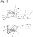
- the patent document 1 discloses a structure shown in Figs. 9 to 12 as a two-plate structure shim assembly.
- a shim assembly 5 constituted of an inside shim plate 3 and an outside shim plate 4 is mounted on the back surface of a pressure plate 2 constituting a pad 1.
- the pad 1 is formed such that a lining 6 is attached and fixed to the front surface (which, when mounting the assembly to the disk brake, is opposed to the side surface of the rotor) of the pressure plate 2 with a large connecting force in a manner to be prevented against movement by brake torque applied in braking.
- the inside shim plate 3 is made of a metal plate and includes a flat plate-shaped inside shim main body 7 and three inside shim locking pieces 8a, 8b, 8c formed bent toward the pressure plate 2 in a total of three portions, namely, the peripheral-direction central portion of the outer peripheral edge and the peripheral-direction two near-to-end portions of the inner peripheral edge of the inside shim main body 7.
- the inside shim main body 7 has multiple opening-holes 9, 9 for holding grease.
- the tip half portion of each of the inside shim locking pieces 8a, 8b, 8c is formed such that the axial-direction middle portion thereof is bent toward the peripheral edge of the pressure plate 2, thereby providing a substantially [doglegged] shape.
- the pressure plate 2 includes, in the radial direction, an radially-outer-side locking recess 10 formed in the peripheral-direction central portion of the outer peripheral edge thereof, and a pair of steps 11, 11 formed in the peripheral-direction near-to-end two portions of the inner peripheral edge thereof. While the inside shim locking piece 8a on the radially-outer-side is engaged into the radially-outer-side locking recess 10 and the inside shim locking pieces 8b, 8c on the radially-inner-side are engaged into the steps 11, 11, the inside shim plate 3 holds the pressure plate 2 from both sides in the radial direction through the inside shim locking pieces 8a, 8b, 8c. In this state, the inside shim plate 3 is mounted on the back side of the pressure plate 2 while it is restricted (substantially prevented) against displacement in the peripheral and radial directions.
- the outside shim plate 4 is made of a metal plate, and includes a flat plate-shaped outside shim main body part 12 and three outside shim locking pieces 13, 13b, and 13c. In the tip half portion of each of the outside shim locking pieces 13, 13b, and 13c as well, the axial-direction middle section thereof is bent toward the peripheral edge of the pressure plate 2, thereby providing a substantially [doglegged] shape. While the outside shim locking pieces 13, 13b, and 13c are overlapped with the inside shim locking pieces 8a, 8b and 8c respectively, the outside shim main body part 12 of the outside shim plate 4 are overlapped with the inside shim main body 7.
- the projecting portions of the tip half portion inner surfaces (surfaces opposed to the peripheral edge of the pressure plate 2) of the outside shim locking pieces 13, 13b, and 13c are elastically engaged into the recesses of the tip half section outer surface (surface opposite to the peripheral edge of the pressure plate 2).
- the outside shim plate 4 is mounted on the inside shim plate 3 in such a manner that it is prevented against separation in the axial direction (thickness direction) and can displace in the peripheral direction.
- the peripheral-direction width dimension of the outside shim locking piece 13a is set smaller than the peripheral-direction width dimension of the inside shim locking piece 8a, and the distance between the peripheral-direction outside edges (which are opposite to each other) of the two outside shim locking pieces 13b, 13c is set smaller than the distance between the two steps 11, 11.
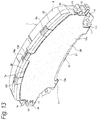
- the patent document 2 discloses a shim assembly 5a shown in Figs. 13 and 14 which can reduce the amount of projection from the peripheral edge of a pressure plate 2a.
- a shim assembly 5a shown in Figs. 13 and 14 which can reduce the amount of projection from the peripheral edge of a pressure plate 2a.
- the second conventional structure of the two inner and outer peripheral edges of an inside shim main body part 7a constituting an inside shim plate 3a, in a total of three portions including the two peripheral-direction near-to-end portions of the outer peripheral edge and the peripheral-direction central portion of the inner periphery edge, there are formed inside shim locking pieces 8d, 8e and 8f respectively bent toward the pressure plate 2a.
- the front half portion inner surfaces of the inside shim locking pieces 8d, 8e formed on the radially-outer-side are respectively elastically contacted with the two locations of the two peripheral-direction near-to-end portion of the outer peripheral edge of the pressure plate 2a. Also, the front half portion inner surface of the inside shim locking pieces 8f formed on the radially-inner-side is engaged with an radially-inner-side locking recess 17 formed in the peripheral-direction central portion of the inner peripheral edge of the pressure plate 2a.
- the outside shim plate 4a includes a flat plate-shaped outside shim main body 12a, three outside shim locking pieces 13d, 13e, 13f, and a pair of locking projection pieces 18, 18.
- the outside shim locking piece 13d formed in the peripheral-direction central portion of the outer peripheral edge of the outside shim main body 12a is engaged with an radially-outer-side locking recess 10a formed in the peripheral-direction central portion of the outer peripheral edge of the pressure plate 2a in such a manner that slight displacement in the peripheral direction is possible.
- the paired outside shim locking pieces 13e and 13f formed in the two peripheral-direction near-to-end portions of the outside shim main body 12a are respectively engaged with a pair of steps 11 formed in the two peripheral-direction near-to-end portions of the inner peripheral edge of the pressure plate 2a.
- the locking projection pieces 18, 18 formed projecting in the peripheral direction from the radial direction central portions of the two peripheral-direction end edges of the outside shim main body 12a are engaged with the two locking opening-holes 15, 15 of the inside shim plate 3a, thereby preventing the outside shim plate 4a against dropout.
- the inside shim plate 3a is mounted on the back surface of the pressure plate 2a in such a manner that it is positioned in the diametric and peripheral directions; and, the outside shim plate 4a is mounted on the inside shim plate 3a in such a manner that it is positioned radially and can displace slightly in the peripheral direction.
- the inside shim locking pieces 8d, 8e, 8f and outside shim locking pieces 13d, 13e, 13f are not overlapped radially, the amounts of projection of the outside shim locking pieces 13d, 13e, 13f from the peripheral edge of the pressure plate 2a can be reduced. Therefore, regardless of the structure of a disk brake, the shim assembly 5a and the other composing parts of the disk brake are made hard to interfere with each other, thereby enabling enhancement in the freedom of design of the disk brake.
- the bending direction of the two locking bent portions 14, 14 of the two peripheral-direction end portions of the inside shim plate 3a is opposite to that of the inside shim locking pieces 8d, 8e and 8f.
- This increases the number of working steps when the inside shim plate 3a is manufactured by press working, thereby increasing the working cost of the inside shim plate 3a.
- the operation to engage the two locking projection pieces 18, 18 of the outside shim plate 4a with the locking opening-holes 15, 15 of the two locking bent portions 14, 14 is also troublesome, thereby raising a possibility of increasing the cost.
- the invention in view of the above circumstances, aims at realizing an inexpensive structure which can assemble together two inside and outside shim plates such that they can displace in the peripheral direction relative to each other and are prevented from separating unexpectedly from each other, and also can minimize the amount of projection of a pad from the two inner and outer peripheral edges of a pressure plate.
- the invention's object is obtained by a shim assembly with the features of claim 1.
- a shim assembly for a disk brake comprising:
- the shim assembly may be configured such that: at least one engaging pawl is provided in an outer peripheral edges of the inside shim main body; at least one engaging pawl is provided in an inner peripheral edges of the inside shim main body; the outside shim locking piece provided in an outer peripheral edge of the outside shim main body is engaged with the engaging pawl formed in the outer peripheral edge of the inside shim main body so as to cover the engaging pawl formed in the outer peripheral edge of the inside shim main body from outward in the radial direction; and the outside shim locking piece provided in an inner peripheral edge of the outside shim main body is engaged with the engaging pawl provided in the inner peripheral edge of the inside shim main body so as to cover the engaging pawl provided in the inner peripheral edge of the inside shim main body from outward in the radial direction.
- one engaging pawl may be provided in the outer peripheral edge of the inside shim main body, and two engaging pawls may be provided in the inner peripheral edge of the inside shim main body.
- a shim assembly 5b for a disk brake of this embodiment includes an inside shim plate 3b and an outside shim plate 4b, and is mounted onto a pad 1.
- the pad 1 includes a pressure plate 2b and a lining 6 attached and fixed to the front surface of the pressure plate 2b, and is arranged in a portion opposed to the axial side surface of a rotor.
- the pressure plate 2b includes, in the peripheral-direction central portion of the outer peripheral edge thereof, a radially-outer-side locking recess 10b which includes, in the peripheral-direction two side portions thereof, a pair of radially-outer-side steps 19 and 19 respectively having a side surface facing outward in the peripheral direction.
- the pressure plate 2b also includes, in the peripheral-direction two near-to-end portions of the inner peripheral edge thereof, a pair of radially-inner-side first steps 20 and 20 respectively having a side surface facing inward in the peripheral direction, and, in the portions thereof nearer to the peripheral-direction center thereof than the first steps 20, 20, a pair of radially-inner-side second steps 21 and 21 respectively having a side surface facing outward in the peripheral direction. And, the peripheral-direction outside surfaces of the second steps 21, 21 and the peripheral-direction inside surfaces of the first steps 20, 20 are opposed to each other in the peripheral direction.
- an anticorrosive and elastic metal plate such as a spring stainless steel plate or a spring stainless steel plate coated with rubber on a surface opposed to the back surface of the pressure plate 2b may be punched, or bent, or wire-cut by press working.
- the inside shim plate 3b includes an inside shim main body 7b, four inside shim locking pieces 8g, 8h, 8i, 8j and three engaging pawls 22a, 22b, 22c.
- the shim main body 7b is formed in a flat plate shape and includes in its multiple locations opening-holes (long holes) 9, 9 for holding therein grease for lubrication.
- each of the inside shim locking pieces 8g, 8h, 8i, 8j includes a flat plate-shaped base half part extending radially from the peripheral edge of the shim main body 7b and a front half part bent toward the pressure plate 2b from the tip end edge of the base half part.
- each of the inside shim locking pieces 8g, 8h, 8i, 8j is bent in the axial-direction middle portion thereof toward the peripheral edge of the pressure plate 2b to provide a substantially "dogleg" shape.
- the front half part inner surfaces of the two inside shim locking pieces 8g and 8h are elastically contacted with two locations between the peripheral-direction central portion of the outer peripheral edge of the pressure plate 2b and two ends, and the two inside shim locking pieces 8i and 8j are elastically contacted with two locations near to the peripheral-direction two ends of the inner peripheral edge of the pressure plate 2b.
- the inside shim main body 7b is contacted with the back surface of the pressure plate 2b.
- the inside shim 3b is mounted onto the back surface side of the pressure plate 2b in such a manner that its peripheral and radial direction displacement is (substantially) restricted.
- the engaging pawls 22a, 22b and 22c are formed.
- the engaging pawl 22a formed on the radially-outer-side includes a flat plate-shaped base half part and a front half part bent about 20 to 30 degrees toward the pressure plate 2b as it goes toward its tip end.
- two engaging pawls 22b and 22c are formed as a flat plate shape as a whole. Also, with the inside shim plate 3b mounted on the back surface of the pressure plate 2b, the tip end edges of the engaging pawls 22a, 22b and 22c slightly project radially from the peripheral edge of the pressure plate 2b.
- the outside shim plate 4b is formed by blanking, or bending or wire-cutting an anticorrosive and elastic metal plate such as a spring stainless steel plate by press working, and includes a flat plate-shaped outside shim main body 12b to be overlapped with the inside shim main body 7b of the inside shim plate 3b, and three outside shim locking pieces 13g, 13h and 13i.
- an anticorrosive and elastic metal plate such as a spring stainless steel plate
- Each of the outside shim locking pieces 13g, 13h and 13i includes a flat plate-shaped base half part extending radially from the peripheral edge of the outside shim main body 12b and a front half part bent toward the pressure plate 2b from the tip end edge of the base half part.
- the front half part of each of the outside shim locking pieces 13g, 13h and 13i also is bent in the axial-direction middle portion thereof toward the peripheral edge of the pressure plate 2b to provide a substantially "dogleg" shape.
- the radially-outer-side outside shim locking piece 13g is engaged with the radially-outer-side locking recess 10b and the two radially-inner-side outside shim locking pieces 13h and 13i are engaged with the radially-inner-side first steps 20 and 20 in such a manner that the peripheral-direction slight displacement thereof is allowed, the front half part inner surface of the piece 13g is contacted or adjacently opposed to the outer peripheral edge of the pressure plate 2b in the portion of the radially-outer-side locking recess 10b, and the two pieces 13h and 13i at the radially inner side are contacted or adjacently opposed to the two locations of the pressure plate 2b existing near the two peripheral-direction ends thereof.
- the outside shim locking pieces 13g, 13h and 13i while ensuring the radial direction positioning of the outside shim plate 4b relative to the pressure plate 2b, may only enable the outside shim plate 4b to displace in the peripheral direction, but the outside shim plate 4b must not always be elastically contacted with the peripheral edge of the pressure plate 2b.
- the radially-outer-side outside shim locking piece 13g is engaged with the radially-outer-side locking recess 10b and is also engaged with the tip end edge of the radially-outer-side engaging pawl 22a of the inside shim plate 3b in such a manner that it covers the engaging pawl 22a from outward in the radial direction.
- the two radially-inner-side outside shim locking pieces 13h and 13i are engaged with the radially-inner-side first steps 20 and 20 and are also engaged with the tip end edges of the radially-inner-side engaging pawls 22b and 22c of the inside shim plate 3b in a manner to cover the engaging pawls 22b and 22c from inward in the radial direction.
- Such engaging operation can be performed easily while elastically deforming the pieces 13g, 13h and 13i through their contact with the tip ends of the engaging pawls 22a, 22b and 22c.
- the outside shim plate 4b is mounted on the inside shim plate 3b in such a manner that radial direction positioning is ensured and slight displacement in the peripheral direction is allowed. Also, with this embodiment, in such mounted state, the amount of the radial direction outward projection of the outside shim locking piece 13b from the outer periphery (circumscribed circle) of the pressure plate 2b, similarly to the conventional first structure, can be sufficiently reduced when compared with a structure in which inside and outside shim locking pieces are overlapped.
- the two shim plates 3b and 4b after previously assembled together (as a shim assembly 5b), may be assembled to the pressure plate 2b, or the inside shim plate 3b and outside shim plate 4b may be assembled sequentially to the pressure plate 2b.
- the shapes of the respective composing parts are improved.
- the peripheral-direction shapes of the outside shim locking pieces 13g, 13h and 13i are formed as straight line shapes parallel to each other and, in such portions of the peripheral edge of the pressure plate 2b as are rubbed against the front half part inner surfaces, there are formed partially cylindrical surface shaped projections 23a, 23b respectively.
- the front half part inner surfaces of the outside shim locking pieces 13g, 13h and 13i are contacted with the top portions (portions projecting most in the radial direction) of the projections 23a, 23b, while the peripheral-direction position of the outside shim plate 4b relative to the pressure plate 2b is defined as a neutral position.
- the peripheral-direction side edges of the front half parts of the outside shim locking pieces 13g, 13h and 13i are separated from the peripheral edge of the pressure plate 2b.
- the peripheral-direction side edges of the front half parts of the outside shim locking pieces 13g, 13h and 13i which are sharp end edges, are not contacted with the peripheral edge of the pressure plate 2b.
- the above-structured shim assembly 5b for a disk brake of the embodiment there can be realized an inexpensive structure which can assemble together the inside and outside shim plates 3b and 4b in such a manner that they can displace relative to each other in the peripheral direction and can be prevented from separating unexpectedly from each other, and also can minimize the amount of projection of the locking pieces from the inner and outer peripheral edges of the pressure plate 2b the pad 1.
- the engaging pawls 22a, 22b and 22c are arranged at the positions out of the inside shim locking pieces 8g, 8h, 8i and 8j provided for mounting the inside shim plate 3b onto the pressure plate 2b.
- the outside shim locking pieces 13g, 13h and 13i formed in the outside shim plate 4b are engaged with the engaging pawls 22a, 22b and 22c in such a manner that the former cover the latter from the radial direction, thereby preventing the inside and outside shim plates 3b and 4b against mutual separation.
- the inside shim locking pieces 8g, 8h, 8i, 8j provided in the inside shim plate 3b and the outside shim locking pieces 13g, 13h and 13i provided in the outside shim plate 4b need not be overlapped with each other. This can minimize the amount of projection of the outside shim locking pieces 13g, 13h and 13i from the peripheral edges of the pressure plate 2b. Consequently, regardless of the structure of a disk brake (whether it is a floating type or an opposed piston type, and, regardless of the number of pistons), the shim assembly 5b for a disk brake and the other composing parts of the disk brake are hard to interfere with each other, thereby enabling enhancement in the freedom of design of the disk brake.
- the engaging pawls 22a, 22b and 22c each having a flat plate shape or bent in the same direction as the inside shim locking pieces 8g, 8h, 8i, 8j may only be formed, thereby, unlike the second conventional structure shown in Figs. 13 and 14 , eliminating the need to form in the inside shim plate 3b locking bent portions bent oppositely to the inside shim locking pieces 8g, 8h, 8i, 8j.
- an increase in the cost can be prevented.
- the operation to engage the outside shim locking pieces 13g, 13h and 13i with the engaging pawls 22a, 22b and 22c can also be facilitated by contacting the outside shim locking pieces 13g, 13h and 13i with the tip ends of the engaging pawls 22a, 22b and 22c to thereby elastically deform these pieces in the radial direction.
- the front half part of the engaging pawl 22a provided on the radially-outer-side is bent toward the pressure plate 2b relative to the base half part thereof, the operation to engage the outside shim locking piece 13g with such engaging pawl 22a can be further facilitated. Therefore, according to the structure of this embodiment, an increase in the manufacturing cost of the shim assembly 5b for a disk brake can be restricted sufficiently.
- the inner surfaces of the peripheral-direction ends of the front half parts of the outside shim locking pieces 13g, 13h and 13i provided in the outside shim plate 4b which, according to braking and release of braking, displaces in the peripheral direction relative to the pressure plate 2b are separated from the peripheral edge of the pressure plate 2b. This can prevent the peripheral-direction end edges of the outside shim locking pieces 13g, 13h and 13i from biting into the peripheral edge of the pressure plate 2b, thereby enabling smooth peripheral- direction displacement of the outside shim plate 4b relative to the pressure plate 2b.
- the above-structured shim assembly for a disk brake of the invention there can be realized an inexpensive structure which can assemble together two inside and outside shim plates such that they can displace in the peripheral direction relative to each other and are prevented from separating unexpectedly from each other, and also can minimize the amount of projection of the shim plate from the two inner and outer peripheral edges of a pressure plate of a pad.
- the engaging pawls are formed in such positions of the inside shim plate as are out of the inside shim locking pieces formed to mount the inside shim plate onto the pressure plate and the outside shim locking pieces formed in the outside shim plate are engaged with the engaging pawls while covering the engaging pawls, thereby preventing the inside and outside shim plates against mutual separation.
- the inside shim locking pieces formed in the inside shim plate and the outside shim locking pieces formed in the outside shim plate may not be overlapped with each other. This can minimize the amount of projection of the locking pieces from the peripheral edge of the pressure plate.
- the engaging pawls each having a flat plate-shaped shape or bent in the same direction as the inside shim locking pieces may only be formed.
- no locking bent portion bent oppositely to the outside shim locking pieces need not be formed in the inside shim plate.
- the operation to engage the outside shim locking pieces with the engaging pawls can be facilitated by elastically deforming the outside shim locking pieces through contact with the tip ends of the engaging pawls. Therefore, according to the invention, an increase in the manufacturing cost of the shim assembly for a disk brake can be restricted sufficiently.
- the number of shim plates constituting the shim assembly for a disk brake of the invention is not restricted to two.
- the invention can also apply to a structure which holds a third shim plate (for example, an intermediate shim plate) between a pressure plate and an inside shim plate, or between an inside shim plate and an outside shim plate.
Description
- This application is based on Japanese Patent Application (No.
2014-236581) filed on November 21, 2014 - The invention relates to an improved shim assembly for a disk brake which is incorporated into a disk brake used to brake a vehicle to reduce brake squeal produced by vibration of a pad in braking and to reduce uneven abrasion of a lining of the pad.
- A disk brake used to brake a vehicle is structured such that a pair of pads are arranged across a rotor rotatable together with a wheel and, in braking, the pads are pressed against the two axial side surfaces of the rotor. The basic structure of such disk brake includes two types, that is, a floating type and an opposed piston type. In any structure, in braking, a rotor rotating together with the wheel is firmly pinched from the two axial sides thereof by a pair of pads. The two pads have their linings attached to the front surface of a pressure plate having sufficient rigidity. In braking, the pads press the back surface of the pressure plate to thereby cause the front surfaces of the linings and the two axial side surfaces of the rotor to rub each other.
- Here, in the specification and claims of the invention, "an axial direction", "peripheral direction" and "radial direction" mean, unless otherwise specified, the "axial direction", "peripheral direction" and "radial direction" of a rotor when a shim assembly for disk brake is assembled to a disk brake. Also, "peripheral edge" means the "inner or outer peripheral edge" of the rotor in the radial direction.
- In braking, a frictional force receiving portion, namely, a contact portion between the rotor two axial side surfaces and the front surfaces of the pad linings, and an anchor portion for supporting brake toque applied to the pads, namely, a contact portion between the pressure plate and a support or a caliper, deviate axially from each other at least by an amount equivalent to the thickness of the pad linings. And, according to the deviation amount equivalent to the thickness, the pads receive moment in a direction where the turn-in sides of the rotor approach each other (fall down on each other), whereby the attitudes of the pads are easy to be unstable. In braking, when the attitudes of the pads get unstable, the movements of the pads are hard to be smooth, thereby causing the pads to vibrate. Thus, noises called squeals can occur and the degree of uneven abrasion of the linings increases greatly.
- To ease such squeals and uneven abrasion, conventionally, a shim plate is widely held between the back surface of a pressure plate constituting the pad and the tip end face of a piston or the inside surface of a caliper pawl part serving as a pressure surface for pressing such back surface. Such shim plate has a simple plate structure but, to enhance the squeal and uneven abrasion reduction effect, there is widely used a two-plate structure in which inside and outside shim plates are superimposed on top of each other. Also, there is conventionally known a structure in which the inside and outside shim plates are combined together such that, while being prevented against separation in the thickness direction, they can displace in the peripheral direction.
- For example, the patent document 1 discloses a structure shown in
Figs. 9 to 12 as a two-plate structure shim assembly. In the illustrated example, a shim assembly 5 constituted of aninside shim plate 3 and anoutside shim plate 4 is mounted on the back surface of apressure plate 2 constituting a pad 1. The pad 1 is formed such that alining 6 is attached and fixed to the front surface (which, when mounting the assembly to the disk brake, is opposed to the side surface of the rotor) of thepressure plate 2 with a large connecting force in a manner to be prevented against movement by brake torque applied in braking. Theinside shim plate 3 is made of a metal plate and includes a flat plate-shaped inside shim main body 7 and three insideshim locking pieces pressure plate 2 in a total of three portions, namely, the peripheral-direction central portion of the outer peripheral edge and the peripheral-direction two near-to-end portions of the inner peripheral edge of the inside shim main body 7. The inside shim main body 7 has multiple opening-holes shim locking pieces pressure plate 2, thereby providing a substantially [doglegged] shape. - The
pressure plate 2 includes, in the radial direction, an radially-outer-side locking recess 10 formed in the peripheral-direction central portion of the outer peripheral edge thereof, and a pair ofsteps shim locking piece 8a on the radially-outer-side is engaged into the radially-outer-side locking recess 10 and the insideshim locking pieces steps inside shim plate 3 holds thepressure plate 2 from both sides in the radial direction through the insideshim locking pieces inside shim plate 3 is mounted on the back side of thepressure plate 2 while it is restricted (substantially prevented) against displacement in the peripheral and radial directions. - The
outside shim plate 4 is made of a metal plate, and includes a flat plate-shaped outside shimmain body part 12 and three outsideshim locking pieces shim locking pieces pressure plate 2, thereby providing a substantially [doglegged] shape. While the outsideshim locking pieces shim locking pieces main body part 12 of theoutside shim plate 4 are overlapped with the inside shim main body 7. In this case, the projecting portions of the tip half portion inner surfaces (surfaces opposed to the peripheral edge of the pressure plate 2) of the outsideshim locking pieces outside shim plate 4 is mounted on theinside shim plate 3 in such a manner that it is prevented against separation in the axial direction (thickness direction) and can displace in the peripheral direction. For this purpose, the peripheral-direction width dimension of the outsideshim locking piece 13a is set smaller than the peripheral-direction width dimension of the insideshim locking piece 8a, and the distance between the peripheral-direction outside edges (which are opposite to each other) of the two outsideshim locking pieces steps - In the above-structured first conventional structure, since the inside
shim locking pieces shim locking pieces shim locking pieces pressure plate 2 are large. This requires consideration for interference with the other composing member of the disk brake, for example, a caliper. The restricted installation space of the disk brake requires large rigidity of the composing part such as the caliper. Thus, the need of consideration for interference prevention raises a disadvantage in securing the freedom of design of the disk brake. - In view of the above circumstances, for example, the
patent document 2 discloses ashim assembly 5a shown inFigs. 13 and14 which can reduce the amount of projection from the peripheral edge of apressure plate 2a. In the second conventional structure, of the two inner and outer peripheral edges of an inside shimmain body part 7a constituting an insideshim plate 3a, in a total of three portions including the two peripheral-direction near-to-end portions of the outer peripheral edge and the peripheral-direction central portion of the inner periphery edge, there are formed insideshim locking pieces pressure plate 2a. The front half portion inner surfaces of the insideshim locking pieces pressure plate 2a. Also, the front half portion inner surface of the insideshim locking pieces 8f formed on the radially-inner-side is engaged with an radially-inner-side locking recess 17 formed in the peripheral-direction central portion of the inner peripheral edge of thepressure plate 2a. - On the two peripheral-direction ends of the inside shim
main body part 7a, there are formed a pair of lockingbent portions pressure plate 2a. In the width direction (radial direction) central portions of the base ends of the twolocking bent portions holes bent portions guide inclination portions - The
outside shim plate 4a includes a flat plate-shaped outside shimmain body 12a, three outsideshim locking pieces locking projection pieces shim locking piece 13d formed in the peripheral-direction central portion of the outer peripheral edge of the outside shimmain body 12a is engaged with an radially-outer-side locking recess 10a formed in the peripheral-direction central portion of the outer peripheral edge of thepressure plate 2a in such a manner that slight displacement in the peripheral direction is possible. The paired outsideshim locking pieces main body 12a are respectively engaged with a pair ofsteps 11 formed in the two peripheral-direction near-to-end portions of the inner peripheral edge of thepressure plate 2a. Thelocking projection pieces main body 12a are engaged with the two locking opening-holes inside shim plate 3a, thereby preventing theoutside shim plate 4a against dropout. - In the second conventional example, with the above structure, the
inside shim plate 3a is mounted on the back surface of thepressure plate 2a in such a manner that it is positioned in the diametric and peripheral directions; and, theoutside shim plate 4a is mounted on theinside shim plate 3a in such a manner that it is positioned radially and can displace slightly in the peripheral direction. And, since the insideshim locking pieces shim locking pieces shim locking pieces pressure plate 2a can be reduced. Therefore, regardless of the structure of a disk brake, theshim assembly 5a and the other composing parts of the disk brake are made hard to interfere with each other, thereby enabling enhancement in the freedom of design of the disk brake. - However, in the above-mentioned second conventional structure, the bending direction of the two
locking bent portions inside shim plate 3a is opposite to that of the insideshim locking pieces inside shim plate 3a is manufactured by press working, thereby increasing the working cost of theinside shim plate 3a. Also, the operation to engage the twolocking projection pieces outside shim plate 4a with the locking opening-holes locking bent portions - [Patent Document 1]
JP 2006-200560 A - [Patent Document 2]
JP 2013-061012 A - The invention, in view of the above circumstances, aims at realizing an inexpensive structure which can assemble together two inside and outside shim plates such that they can displace in the peripheral direction relative to each other and are prevented from separating unexpectedly from each other, and also can minimize the amount of projection of a pad from the two inner and outer peripheral edges of a pressure plate.
The invention's object is obtained by a shim assembly with the features of claim 1. - According to one advantageous aspect of the present invention, there may be provided a shim assembly for a disk brake comprising:
- an inside shim plate configured to be mounted onto a back surface of a pressure plate of a pad for a disk brake, and including a flat plate-shaped inside shim main body;
- an outside shim plate including a flat plate-shaped outside shim main body overlapped with the inside shim main body of the inside shim plate;
- a plurality of inside shim locking pieces, provided in a peripheral edge of the inside shim main body of the inside shim plate, and bent toward the pressure plate so as to be elastically contacted with the peripheral edge of the pressure plate, so that the inside shim plate is mounted onto the back surface of the pressure plate in a state that displacement of the inside shim plate in radial and peripheral directions is restricted;
- outside shim locking pieces, provided in a peripheral edge of the outside shim main body of the outside shim plate, and bent toward the pressure plate so as
to be contacted with or adjacently oppose to portions of the peripheral edge of the pressure plate which are positioned out of portions thereof which the inside shim locking pieces contact, so that the outside shim plate is overlapped with a back surface of the inside shim plate in a state that displacement of the outside shim plate in the peripheral direction is allowed and displacement of the outside shim plate in the radial direction is restricted; and - engaging pawls, provided in portions of the peripheral edge of the inside shim main body which are positioned out of portions thereof where the inside shim locking pieces are formed, each of which having a flat plate shape as a whole or having a tip end bent toward the pressure plate, and projected from the peripheral edge of the pressure plate in a state that the inside shim plate is mounted on the pressure plate,
- wherein the outside shim locking pieces are respectively engaged with the engaging pawls so as to cover the engaging pawls, to prevent the outside shim plate against separation from the inside shim plate.
- The shim assembly may be configured such that: at least one engaging pawl is provided in an outer peripheral edges of the inside shim main body; at least one engaging pawl is provided in an inner peripheral edges of the inside shim main body; the outside shim locking piece provided in an outer peripheral edge of the outside shim main body is engaged with the engaging pawl formed in the outer peripheral edge of the inside shim main body so as to cover the engaging pawl formed in the outer peripheral edge of the inside shim main body from outward in the radial direction; and the outside shim locking piece provided in an inner peripheral edge of the outside shim main body is engaged with the engaging pawl provided in the inner peripheral edge of the inside shim main body so as to cover the engaging pawl provided in the inner peripheral edge of the inside shim main body from outward in the radial direction.
- In the shim assembly, one engaging pawl may be provided in the outer peripheral edge of the inside shim main body, and two engaging pawls may be provided in the inner peripheral edge of the inside shim main body.
-
-
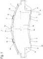
Fig. 1 is a back view of a shim assembly according to an embodiment of the invention, while it is mounted on a pad. -
Fig. 2 is a plan view of the shim assembly. -
Fig. 3 is a side view of the shim assembly when viewed from the right side ofFig. 1 . -
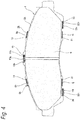
Fig. 4 is a front view of the shim assembly. -
Fig. 5 is a section view taken along the A-O-O-A line ofFig. 1 . -
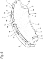
Fig. 6 is a perspective view of the shim assembly, when viewed from the back side and from outward in the radial direction. -
Fig. 7 is an exploded perspective of the shim assembly. -
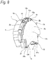
Fig. 8 is a perspective view of the shim assembly, when viewed from the back side and from one side in the peripheral direction. -
Fig. 9 is a back view of a shim assembly according to a first example of a conventional structure, while it is mounted on a pad. -
Fig. 10 is a partially omitted back view of the first conventional shim assembly, taken along the B-O-O-B line ofFig. 9 . -
Fig. 11 is a perspective view of the first conventional shim assembly, when viewed from the back side and from outward in the radial direction. -
Fig. 12 is an exploded perspective of the first conventional shim assembly. -
Fig. 13 is a perspective view of a shim assembly according to a second example of the conventional structure while it is mounted on a pad, when viewed from the back side and from outward in the radial direction. -
Fig. 14 is an exploded perspective view of the second conventional example. - Description is given of an embodiment of the invention with reference to
Figs. 1 to 8 . Ashim assembly 5b for a disk brake of this embodiment includes aninside shim plate 3b and anoutside shim plate 4b, and is mounted onto a pad 1. The pad 1 includes apressure plate 2b and alining 6 attached and fixed to the front surface of thepressure plate 2b, and is arranged in a portion opposed to the axial side surface of a rotor. Thepressure plate 2b includes, in the peripheral-direction central portion of the outer peripheral edge thereof, a radially-outer-side locking recess 10b which includes, in the peripheral-direction two side portions thereof, a pair of radially-outer-side steps pressure plate 2b also includes, in the peripheral-direction two near-to-end portions of the inner peripheral edge thereof, a pair of radially-inner-side first steps 20 and 20 respectively having a side surface facing inward in the peripheral direction, and, in the portions thereof nearer to the peripheral-direction center thereof than thefirst steps second steps first steps - To form the
inside shim plate 3b, an anticorrosive and elastic metal plate such as a spring stainless steel plate or a spring stainless steel plate coated with rubber on a surface opposed to the back surface of thepressure plate 2b may be punched, or bent, or wire-cut by press working. Theinside shim plate 3b includes an inside shimmain body 7b, four insideshim locking pieces pawls - The shim
main body 7b is formed in a flat plate shape and includes in its multiple locations opening-holes (long holes) 9, 9 for holding therein grease for lubrication. - Of the two inner and outer peripheral edges of the shim
main body 7b, in a total of four locations including two locations between the peripheral-direction central portion and two ends of the outer peripheral edge, and the two locations of the inner peripheral edge existing near to the two peripheral-direction ends thereof, there are formed the four insideshim locking pieces shim locking pieces main body 7b and a front half part bent toward thepressure plate 2b from the tip end edge of the base half part. The front half part of each of the insideshim locking pieces pressure plate 2b to provide a substantially "dogleg" shape. In this embodiment, while the two radially-outer-side insideshim locking pieces side steps shim locking pieces shim locking pieces pressure plate 2b and two ends, and the two insideshim locking pieces pressure plate 2b. That is, while holding thepressure plate 2b from both sides in the radial direction using the radially-outer-side insideshim locking pieces shim locking pieces main body 7b is contacted with the back surface of thepressure plate 2b. In this state, theinside shim 3b is mounted onto the back surface side of thepressure plate 2b in such a manner that its peripheral and radial direction displacement is (substantially) restricted. - Also, of the inner and outer peripheral edges of the inside shim
main body 7b, in a total of three portions out of the portions of the insideshim locking pieces engaging pawls pawls pawl 22a formed on the radially-outer-side includes a flat plate-shaped base half part and a front half part bent about 20 to 30 degrees toward thepressure plate 2b as it goes toward its tip end. Meanwhile, two engagingpawls inside shim plate 3b mounted on the back surface of thepressure plate 2b, the tip end edges of theengaging pawls pressure plate 2b. - The
outside shim plate 4b is formed by blanking, or bending or wire-cutting an anticorrosive and elastic metal plate such as a spring stainless steel plate by press working, and includes a flat plate-shaped outside shimmain body 12b to be overlapped with the inside shimmain body 7b of theinside shim plate 3b, and three outsideshim locking pieces main body 12b, in the peripheral-direction central portion of the outer peripheral edge, there is formed oneoutside locking piece 13g; and, in the two peripheral-direction ends of the inner peripheral edge, there are formed two outsideshim locking pieces shim locking pieces main body 12b and a front half part bent toward thepressure plate 2b from the tip end edge of the base half part. The front half part of each of the outsideshim locking pieces pressure plate 2b to provide a substantially "dogleg" shape. In this embodiment, while the radially-outer-side outsideshim locking piece 13g is engaged with the radially-outer-side locking recess 10b and the two radially-inner-side outsideshim locking pieces piece 13g is contacted or adjacently opposed to the outer peripheral edge of thepressure plate 2b in the portion of the radially-outer-side locking recess 10b, and the twopieces pressure plate 2b existing near the two peripheral-direction ends thereof. That is, the outsideshim locking pieces outside shim plate 4b relative to thepressure plate 2b, may only enable theoutside shim plate 4b to displace in the peripheral direction, but theoutside shim plate 4b must not always be elastically contacted with the peripheral edge of thepressure plate 2b. - Especially, in this embodiment, the radially-outer-side outside
shim locking piece 13g is engaged with the radially-outer-side locking recess 10b and is also engaged with the tip end edge of the radially-outer-sideengaging pawl 22a of theinside shim plate 3b in such a manner that it covers the engagingpawl 22a from outward in the radial direction. And, the two radially-inner-side outsideshim locking pieces side engaging pawls inside shim plate 3b in a manner to cover the engagingpawls pieces engaging pawls outside shim plate 4b from theinside shim plate 3b, theoutside shim plate 4b is mounted on theinside shim plate 3b in such a manner that radial direction positioning is ensured and slight displacement in the peripheral direction is allowed. Also, with this embodiment, in such mounted state, the amount of the radial direction outward projection of the outsideshim locking piece 13b from the outer periphery (circumscribed circle) of thepressure plate 2b, similarly to the conventional first structure, can be sufficiently reduced when compared with a structure in which inside and outside shim locking pieces are overlapped. - Here, the two
shim plates shim assembly 5b), may be assembled to thepressure plate 2b, or theinside shim plate 3b andoutside shim plate 4b may be assembled sequentially to thepressure plate 2b. - Also, in this embodiment, in order to minimize resistance caused when the
outside shim plate 4b is displaced in the peripheral direction relative to thepressure plate 2b and the front half part inner surfaces of the outsideshim locking pieces pressure plate 2b, the shapes of the respective composing parts are improved. Specifically, the peripheral-direction shapes of the outsideshim locking pieces pressure plate 2b as are rubbed against the front half part inner surfaces, there are formed partially cylindrical surface shapedprojections - Therefore, the front half part inner surfaces of the outside
shim locking pieces projections outside shim plate 4b relative to thepressure plate 2b is defined as a neutral position. In this state, the peripheral-direction side edges of the front half parts of the outsideshim locking pieces pressure plate 2b. In other words, the peripheral-direction side edges of the front half parts of the outsideshim locking pieces pressure plate 2b. - According to the above-structured
shim assembly 5b for a disk brake of the embodiment, there can be realized an inexpensive structure which can assemble together the inside andoutside shim plates pressure plate 2b the pad 1. - That is, in the
shim assembly 5b of the embodiment, the engagingpawls shim locking pieces inside shim plate 3b onto thepressure plate 2b. And, the outsideshim locking pieces outside shim plate 4b are engaged with the engagingpawls outside shim plates Figs. 9 to 12 , the insideshim locking pieces inside shim plate 3b and the outsideshim locking pieces outside shim plate 4b need not be overlapped with each other. This can minimize the amount of projection of the outsideshim locking pieces pressure plate 2b. Consequently, regardless of the structure of a disk brake (whether it is a floating type or an opposed piston type, and, regardless of the number of pistons), theshim assembly 5b for a disk brake and the other composing parts of the disk brake are hard to interfere with each other, thereby enabling enhancement in the freedom of design of the disk brake. - Further, in this embodiment, for prevention of mutual separation of the inside and
outside shim plates pawls shim locking pieces Figs. 13 and14 , eliminating the need to form in theinside shim plate 3b locking bent portions bent oppositely to the insideshim locking pieces inside shim plate 3b is manufactured by pressing or by wire cutting, an increase in the cost can be prevented. The operation to engage the outsideshim locking pieces pawls shim locking pieces engaging pawls pawl 22a provided on the radially-outer-side is bent toward thepressure plate 2b relative to the base half part thereof, the operation to engage the outsideshim locking piece 13g with suchengaging pawl 22a can be further facilitated. Therefore, according to the structure of this embodiment, an increase in the manufacturing cost of theshim assembly 5b for a disk brake can be restricted sufficiently. - Further, in this embodiment, the inner surfaces of the peripheral-direction ends of the front half parts of the outside
shim locking pieces outside shim plate 4b which, according to braking and release of braking, displaces in the peripheral direction relative to thepressure plate 2b are separated from the peripheral edge of thepressure plate 2b. This can prevent the peripheral-direction end edges of the outsideshim locking pieces pressure plate 2b, thereby enabling smooth peripheral- direction displacement of theoutside shim plate 4b relative to thepressure plate 2b. - According to the above-structured shim assembly for a disk brake of the invention, there can be realized an inexpensive structure which can assemble together two inside and outside shim plates such that they can displace in the peripheral direction relative to each other and are prevented from separating unexpectedly from each other, and also can minimize the amount of projection of the shim plate from the two inner and outer peripheral edges of a pressure plate of a pad.
- That is, in the shim assembly for a disk brake of the invention, the engaging pawls are formed in such positions of the inside shim plate as are out of the inside shim locking pieces formed to mount the inside shim plate onto the pressure plate and the outside shim locking pieces formed in the outside shim plate are engaged with the engaging pawls while covering the engaging pawls, thereby preventing the inside and outside shim plates against mutual separation. Thus, unlike the first conventional structure shown in
Figs. 9 to 12 , the inside shim locking pieces formed in the inside shim plate and the outside shim locking pieces formed in the outside shim plate may not be overlapped with each other. This can minimize the amount of projection of the locking pieces from the peripheral edge of the pressure plate. Further, in the invention, for prevention of mutual separation between the inside and outside shim plates, the engaging pawls each having a flat plate-shaped shape or bent in the same direction as the inside shim locking pieces may only be formed. Thus, unlike the second conventional structure shown inFigs. 13 and14 , no locking bent portion bent oppositely to the outside shim locking pieces need not be formed in the inside shim plate. Also, the operation to engage the outside shim locking pieces with the engaging pawls can be facilitated by elastically deforming the outside shim locking pieces through contact with the tip ends of the engaging pawls. Therefore, according to the invention, an increase in the manufacturing cost of the shim assembly for a disk brake can be restricted sufficiently. - The number of shim plates constituting the shim assembly for a disk brake of the invention is not restricted to two. The invention can also apply to a structure which holds a third shim plate (for example, an intermediate shim plate) between a pressure plate and an inside shim plate, or between an inside shim plate and an outside shim plate.
Claims (3)
- A shim assembly for a disk brake comprising:an inside shim plate (3b) configured to be mounted onto a back surface of a pressure plate (2b) of a pad for a disk brake, and including a flat plate-shaped inside shim main body (7b);an outside shim plate (4b) including a flat plate-shaped outside shim main body (12b) overlapping with the inside shim main body (7b) of the inside shim plate (3b);a plurality of inside shim locking pieces (8g, 8h, 8i, 8j), provided in a peripheral edge of the inside shim main body (7b) of the inside shim plate (3b), bent toward the pressure plate (2b) and configured to be elastically contacted with the peripheral edge of the pressure plate (2b), outside shim locking pieces (13g, 13h, 13i), provided in a peripheral edge of the outside shim main body (12b) of the outside shim plate (4b), bent toward the pressure plate (2b) and configured to be contacted with or adjacently oppose to portions of the peripheral edge of the pressure plate (2b), which are positioned out of portions thereof where the inside shim locking pieces contact, so that the outside shim plate (4b) is overlapping with a back surface of the inside shim plate (3b)
characterized byengaging pawls (22a, 22b, 22c), provided in portions of the peripheral edge of the inside shim main body (7b) which are positioned out of portions thereof where the inside shim locking pieces (8g. 8h, 8i, 8j) are formed, each of which having a flat plate shape as a whole or having a tip end bent toward the pressure plate (2b), and configured to project from the peripheral edge of the pressure plate (2b) in a state that the inside shim plate (3b) is mounted on the pressure plate (2b),wherein the outside shim locking pieces (13g, 13h, 13i) are respectively engaged with the engaging pawls (22a, 22b, 22c) so as to cover the engaging pawls (22a, 22b, 22c), to prevent the outside shim plate (4b) against separation from the inside shim plate (3b). - The shim assembly according to Claim 1, wherein
at least one engaging pawl (22a) is provided in an outer peripheral edges of the inside shim main body (7b),
at least one engaging pawl (22b, 22c) is provided in an inner peripheral edges of the inside shim main body (7b),
the outside shim locking piece (13g) provided in an outer peripheral edge of the outside shim main body (12b) is engaged with the engaging pawl (22a) formed in the outer peripheral edge of the inside shim main body (7b) so as to cover the engaging pawl (22a) formed in the outer peripheral edge of the inside shim main body (7b) from outward in the radial direction, and
the outside shim locking piece (13h, 13i) provided in an inner peripheral edge of the outside shim main body (12b) is engaged with the engaging pawl (22b, 22c) provided in the inner peripheral edge of the inside shim main body (7b) so as to cover the engaging pawl (22b, 22c) provided in the inner peripheral edge of the inside shim main body (7b) from outward in the radial direction. - The shim assembly according to Claim 2, wherein
one engaging pawl (22a) is provided in the outer peripheral edge of the inside shim main body (7b), and
two engaging pawls (22b, 22c) are provided in the inner peripheral edge of the inside shim main body (7b).
Applications Claiming Priority (1)
| Application Number | Priority Date | Filing Date | Title |
|---|---|---|---|
| JP2014236581A JP6433262B2 (en) | 2014-11-21 | 2014-11-21 | Shim assembly for disc brake |
Publications (2)
| Publication Number | Publication Date |
|---|---|
| EP3026287A1 EP3026287A1 (en) | 2016-06-01 |
| EP3026287B1 true EP3026287B1 (en) | 2018-10-24 |
Family
ID=54548095
Family Applications (1)
| Application Number | Title | Priority Date | Filing Date |
|---|---|---|---|
| EP15195067.2A Active EP3026287B1 (en) | 2014-11-21 | 2015-11-18 | Shim assembly for disk brake |
Country Status (4)
| Country | Link |
|---|---|
| US (1) | US9759277B2 (en) |
| EP (1) | EP3026287B1 (en) |
| JP (1) | JP6433262B2 (en) |
| CN (1) | CN105626724B (en) |
Families Citing this family (10)
| Publication number | Priority date | Publication date | Assignee | Title |
|---|---|---|---|---|
| US10252770B2 (en) | 2009-12-15 | 2019-04-09 | Syscend, Inc. | Hub and disk brake system and apparatus |
| US11390355B1 (en) | 2009-12-15 | 2022-07-19 | Syscend, Inc. | Hydraulic brake system and apparatus |
| US11919605B1 (en) | 2014-01-31 | 2024-03-05 | Syscend, Inc. | Hydraulic brake system and apparatus |
| JP6284831B2 (en) * | 2014-06-09 | 2018-02-28 | 曙ブレーキ工業株式会社 | Disc brake pad assembly |
| JP6762900B2 (en) * | 2017-03-28 | 2020-09-30 | 曙ブレーキ工業株式会社 | Laminated shims for disc brakes |
| USD879687S1 (en) * | 2017-07-06 | 2020-03-31 | Syscend, Inc. | Brake slider |
| JP7168415B2 (en) * | 2018-10-31 | 2022-11-09 | 曙ブレーキ工業株式会社 | Shim, shim mounting method, and pad assembly for disc brake |
| KR20220053371A (en) * | 2020-10-22 | 2022-04-29 | 현대모비스 주식회사 | Disk break apparatus |
| US11746840B2 (en) * | 2021-05-28 | 2023-09-05 | ZF Active Safety US Inc. | Retention system for shim on backplate of brake pad assembly |
| DE102021127932A1 (en) | 2021-10-27 | 2023-04-27 | Bayerische Motoren Werke Aktiengesellschaft | Damping plate of a brake pad assembly |
Family Cites Families (11)
| Publication number | Priority date | Publication date | Assignee | Title |
|---|---|---|---|---|
| JP2561569Y2 (en) * | 1991-06-17 | 1998-01-28 | 日清紡績株式会社 | Shim assembly for disc brake |
| JP3863250B2 (en) * | 1997-05-16 | 2006-12-27 | 株式会社日立製作所 | Disc brake |
| JP3932066B2 (en) * | 1997-09-29 | 2007-06-20 | 株式会社日立製作所 | Disc brake |
| JP4715124B2 (en) | 2004-08-06 | 2011-07-06 | 株式会社アドヴィックス | Laminated shim for disc brake and pad unit having the laminated shim |
| JP3998687B2 (en) * | 2005-01-18 | 2007-10-31 | 曙ブレーキ工業株式会社 | Disc brake pad assembly |
| JP2007085439A (en) | 2005-09-21 | 2007-04-05 | Nissin Kogyo Co Ltd | Disc brake for vehicle |
| US20090000880A1 (en) * | 2006-11-30 | 2009-01-01 | Nissin Kogyo Co., Ltd. | Disc brake shim plate |
| JP5855397B2 (en) * | 2011-09-13 | 2016-02-09 | 曙ブレーキ工業株式会社 | Disc brake pad assembly |
| JP5855398B2 (en) | 2011-09-13 | 2016-02-09 | 曙ブレーキ工業株式会社 | Disc brake pad assembly |
| CA2752900C (en) * | 2011-09-19 | 2017-10-10 | Ray Arbesman | Brake shim having lubricant compartment |
| JP6304879B2 (en) * | 2014-06-09 | 2018-04-04 | 日立オートモティブシステムズ株式会社 | Disc brake, pad and a pair of shims |
-
2014
- 2014-11-21 JP JP2014236581A patent/JP6433262B2/en active Active
-
2015
- 2015-11-12 US US14/939,274 patent/US9759277B2/en active Active
- 2015-11-18 EP EP15195067.2A patent/EP3026287B1/en active Active
- 2015-11-20 CN CN201510811153.9A patent/CN105626724B/en active Active
Non-Patent Citations (1)
| Title |
|---|
| None * |
Also Published As
| Publication number | Publication date |
|---|---|
| US20160146276A1 (en) | 2016-05-26 |
| JP6433262B2 (en) | 2018-12-05 |
| JP2016098912A (en) | 2016-05-30 |
| CN105626724A (en) | 2016-06-01 |
| CN105626724B (en) | 2018-10-30 |
| US9759277B2 (en) | 2017-09-12 |
| EP3026287A1 (en) | 2016-06-01 |
Similar Documents
| Publication | Publication Date | Title |
|---|---|---|
| EP3026287B1 (en) | Shim assembly for disk brake | |
| JP5855398B2 (en) | Disc brake pad assembly | |
| JP6189718B2 (en) | Disc brake pad and disc brake device | |
| JP6261289B2 (en) | Disc brake pad spring | |
| JP5855397B2 (en) | Disc brake pad assembly | |
| EP3153736B1 (en) | Pad assembly for disk brake | |
| EP3680504B1 (en) | Vehicular disc brake | |
| US20230341014A1 (en) | Brake assembly | |
| US10598236B2 (en) | Laminated shim for disc brake | |
| JP6982493B2 (en) | Pad clips, pad clip and return spring assemblies, and floating disc brakes | |
| JP5085591B2 (en) | Combination shim plate for disc brake | |
| WO2023062843A1 (en) | Disk brake and cover component | |
| JP7376430B2 (en) | Disc brake and cover parts | |
| JP5488872B2 (en) | Disc brake | |
| CN117916485A (en) | Disc brake and plate | |
| JP2023090193A (en) | Floating type disc brake device | |
| JP2014070652A (en) | Disc brake, and pad support |
Legal Events
| Date | Code | Title | Description |
|---|---|---|---|
| PUAI | Public reference made under article 153(3) epc to a published international application that has entered the european phase |
Free format text: ORIGINAL CODE: 0009012 |
|
| AK | Designated contracting states |
Kind code of ref document: A1 Designated state(s): AL AT BE BG CH CY CZ DE DK EE ES FI FR GB GR HR HU IE IS IT LI LT LU LV MC MK MT NL NO PL PT RO RS SE SI SK SM TR |
|
| AX | Request for extension of the european patent |
Extension state: BA ME |
|
| 17P | Request for examination filed |
Effective date: 20161201 |
|
| RBV | Designated contracting states (corrected) |
Designated state(s): AL AT BE BG CH CY CZ DE DK EE ES FI FR GB GR HR HU IE IS IT LI LT LU LV MC MK MT NL NO PL PT RO RS SE SI SK SM TR |
|
| GRAP | Despatch of communication of intention to grant a patent |
Free format text: ORIGINAL CODE: EPIDOSNIGR1 |
|
| INTG | Intention to grant announced |
Effective date: 20180606 |
|
| RAP1 | Party data changed (applicant data changed or rights of an application transferred) |
Owner name: AKEBONO BRAKE INDUSTRY CO., LTD. |
|
| RIN1 | Information on inventor provided before grant (corrected) |
Inventor name: KOBAYASHI, NAOKO Inventor name: KOBAYASHI, DAISUKE |
|
| GRAS | Grant fee paid |
Free format text: ORIGINAL CODE: EPIDOSNIGR3 |
|
| GRAA | (expected) grant |
Free format text: ORIGINAL CODE: 0009210 |
|
| AK | Designated contracting states |
Kind code of ref document: B1 Designated state(s): AL AT BE BG CH CY CZ DE DK EE ES FI FR GB GR HR HU IE IS IT LI LT LU LV MC MK MT NL NO PL PT RO RS SE SI SK SM TR |
|
| REG | Reference to a national code |
Ref country code: CH Ref legal event code: EP |
|
| REG | Reference to a national code |
Ref country code: IE Ref legal event code: FG4D |
|
| REG | Reference to a national code |
Ref country code: AT Ref legal event code: REF Ref document number: 1057031 Country of ref document: AT Kind code of ref document: T Effective date: 20181115 |
|
| REG | Reference to a national code |
Ref country code: DE Ref legal event code: R096 Ref document number: 602015018618 Country of ref document: DE |
|
| REG | Reference to a national code |
Ref country code: NL Ref legal event code: MP Effective date: 20181024 |
|
| REG | Reference to a national code |
Ref country code: LT Ref legal event code: MG4D |
|
| REG | Reference to a national code |
Ref country code: AT Ref legal event code: MK05 Ref document number: 1057031 Country of ref document: AT Kind code of ref document: T Effective date: 20181024 |
|
| PG25 | Lapsed in a contracting state [announced via postgrant information from national office to epo] |
Ref country code: NL Free format text: LAPSE BECAUSE OF FAILURE TO SUBMIT A TRANSLATION OF THE DESCRIPTION OR TO PAY THE FEE WITHIN THE PRESCRIBED TIME-LIMIT Effective date: 20181024 |
|
| PG25 | Lapsed in a contracting state [announced via postgrant information from national office to epo] |
Ref country code: LV Free format text: LAPSE BECAUSE OF FAILURE TO SUBMIT A TRANSLATION OF THE DESCRIPTION OR TO PAY THE FEE WITHIN THE PRESCRIBED TIME-LIMIT Effective date: 20181024 Ref country code: AT Free format text: LAPSE BECAUSE OF FAILURE TO SUBMIT A TRANSLATION OF THE DESCRIPTION OR TO PAY THE FEE WITHIN THE PRESCRIBED TIME-LIMIT Effective date: 20181024 Ref country code: FI Free format text: LAPSE BECAUSE OF FAILURE TO SUBMIT A TRANSLATION OF THE DESCRIPTION OR TO PAY THE FEE WITHIN THE PRESCRIBED TIME-LIMIT Effective date: 20181024 Ref country code: BG Free format text: LAPSE BECAUSE OF FAILURE TO SUBMIT A TRANSLATION OF THE DESCRIPTION OR TO PAY THE FEE WITHIN THE PRESCRIBED TIME-LIMIT Effective date: 20190124 Ref country code: IS Free format text: LAPSE BECAUSE OF FAILURE TO SUBMIT A TRANSLATION OF THE DESCRIPTION OR TO PAY THE FEE WITHIN THE PRESCRIBED TIME-LIMIT Effective date: 20190224 Ref country code: NO Free format text: LAPSE BECAUSE OF FAILURE TO SUBMIT A TRANSLATION OF THE DESCRIPTION OR TO PAY THE FEE WITHIN THE PRESCRIBED TIME-LIMIT Effective date: 20190124 Ref country code: HR Free format text: LAPSE BECAUSE OF FAILURE TO SUBMIT A TRANSLATION OF THE DESCRIPTION OR TO PAY THE FEE WITHIN THE PRESCRIBED TIME-LIMIT Effective date: 20181024 Ref country code: PL Free format text: LAPSE BECAUSE OF FAILURE TO SUBMIT A TRANSLATION OF THE DESCRIPTION OR TO PAY THE FEE WITHIN THE PRESCRIBED TIME-LIMIT Effective date: 20181024 Ref country code: ES Free format text: LAPSE BECAUSE OF FAILURE TO SUBMIT A TRANSLATION OF THE DESCRIPTION OR TO PAY THE FEE WITHIN THE PRESCRIBED TIME-LIMIT Effective date: 20181024 Ref country code: LT Free format text: LAPSE BECAUSE OF FAILURE TO SUBMIT A TRANSLATION OF THE DESCRIPTION OR TO PAY THE FEE WITHIN THE PRESCRIBED TIME-LIMIT Effective date: 20181024 |
|
| PG25 | Lapsed in a contracting state [announced via postgrant information from national office to epo] |
Ref country code: RS Free format text: LAPSE BECAUSE OF FAILURE TO SUBMIT A TRANSLATION OF THE DESCRIPTION OR TO PAY THE FEE WITHIN THE PRESCRIBED TIME-LIMIT Effective date: 20181024 Ref country code: SE Free format text: LAPSE BECAUSE OF FAILURE TO SUBMIT A TRANSLATION OF THE DESCRIPTION OR TO PAY THE FEE WITHIN THE PRESCRIBED TIME-LIMIT Effective date: 20181024 Ref country code: GR Free format text: LAPSE BECAUSE OF FAILURE TO SUBMIT A TRANSLATION OF THE DESCRIPTION OR TO PAY THE FEE WITHIN THE PRESCRIBED TIME-LIMIT Effective date: 20190125 Ref country code: PT Free format text: LAPSE BECAUSE OF FAILURE TO SUBMIT A TRANSLATION OF THE DESCRIPTION OR TO PAY THE FEE WITHIN THE PRESCRIBED TIME-LIMIT Effective date: 20190224 Ref country code: AL Free format text: LAPSE BECAUSE OF FAILURE TO SUBMIT A TRANSLATION OF THE DESCRIPTION OR TO PAY THE FEE WITHIN THE PRESCRIBED TIME-LIMIT Effective date: 20181024 |
|
| REG | Reference to a national code |
Ref country code: CH Ref legal event code: PL |
|
| REG | Reference to a national code |
Ref country code: DE Ref legal event code: R097 Ref document number: 602015018618 Country of ref document: DE |
|
| PG25 | Lapsed in a contracting state [announced via postgrant information from national office to epo] |
Ref country code: LU Free format text: LAPSE BECAUSE OF NON-PAYMENT OF DUE FEES Effective date: 20181118 Ref country code: CZ Free format text: LAPSE BECAUSE OF FAILURE TO SUBMIT A TRANSLATION OF THE DESCRIPTION OR TO PAY THE FEE WITHIN THE PRESCRIBED TIME-LIMIT Effective date: 20181024 Ref country code: IT Free format text: LAPSE BECAUSE OF FAILURE TO SUBMIT A TRANSLATION OF THE DESCRIPTION OR TO PAY THE FEE WITHIN THE PRESCRIBED TIME-LIMIT Effective date: 20181024 Ref country code: DK Free format text: LAPSE BECAUSE OF FAILURE TO SUBMIT A TRANSLATION OF THE DESCRIPTION OR TO PAY THE FEE WITHIN THE PRESCRIBED TIME-LIMIT Effective date: 20181024 |
|
| REG | Reference to a national code |
Ref country code: BE Ref legal event code: MM Effective date: 20181130 |
|
| REG | Reference to a national code |
Ref country code: IE Ref legal event code: MM4A |
|
| PG25 | Lapsed in a contracting state [announced via postgrant information from national office to epo] |
Ref country code: SK Free format text: LAPSE BECAUSE OF FAILURE TO SUBMIT A TRANSLATION OF THE DESCRIPTION OR TO PAY THE FEE WITHIN THE PRESCRIBED TIME-LIMIT Effective date: 20181024 Ref country code: RO Free format text: LAPSE BECAUSE OF FAILURE TO SUBMIT A TRANSLATION OF THE DESCRIPTION OR TO PAY THE FEE WITHIN THE PRESCRIBED TIME-LIMIT Effective date: 20181024 Ref country code: CH Free format text: LAPSE BECAUSE OF NON-PAYMENT OF DUE FEES Effective date: 20181130 Ref country code: EE Free format text: LAPSE BECAUSE OF FAILURE TO SUBMIT A TRANSLATION OF THE DESCRIPTION OR TO PAY THE FEE WITHIN THE PRESCRIBED TIME-LIMIT Effective date: 20181024 Ref country code: SM Free format text: LAPSE BECAUSE OF FAILURE TO SUBMIT A TRANSLATION OF THE DESCRIPTION OR TO PAY THE FEE WITHIN THE PRESCRIBED TIME-LIMIT Effective date: 20181024 Ref country code: LI Free format text: LAPSE BECAUSE OF NON-PAYMENT OF DUE FEES Effective date: 20181130 Ref country code: MC Free format text: LAPSE BECAUSE OF FAILURE TO SUBMIT A TRANSLATION OF THE DESCRIPTION OR TO PAY THE FEE WITHIN THE PRESCRIBED TIME-LIMIT Effective date: 20181024 |
|
| PLBE | No opposition filed within time limit |
Free format text: ORIGINAL CODE: 0009261 |
|
| STAA | Information on the status of an ep patent application or granted ep patent |
Free format text: STATUS: NO OPPOSITION FILED WITHIN TIME LIMIT |
|
| 26N | No opposition filed |
Effective date: 20190725 |
|
| PG25 | Lapsed in a contracting state [announced via postgrant information from national office to epo] |
Ref country code: SI Free format text: LAPSE BECAUSE OF FAILURE TO SUBMIT A TRANSLATION OF THE DESCRIPTION OR TO PAY THE FEE WITHIN THE PRESCRIBED TIME-LIMIT Effective date: 20181024 Ref country code: IE Free format text: LAPSE BECAUSE OF NON-PAYMENT OF DUE FEES Effective date: 20181118 Ref country code: FR Free format text: LAPSE BECAUSE OF NON-PAYMENT OF DUE FEES Effective date: 20181224 |
|
| PG25 | Lapsed in a contracting state [announced via postgrant information from national office to epo] |
Ref country code: BE Free format text: LAPSE BECAUSE OF NON-PAYMENT OF DUE FEES Effective date: 20181130 |
|
| PG25 | Lapsed in a contracting state [announced via postgrant information from national office to epo] |
Ref country code: MT Free format text: LAPSE BECAUSE OF NON-PAYMENT OF DUE FEES Effective date: 20181118 |
|
| PG25 | Lapsed in a contracting state [announced via postgrant information from national office to epo] |
Ref country code: TR Free format text: LAPSE BECAUSE OF FAILURE TO SUBMIT A TRANSLATION OF THE DESCRIPTION OR TO PAY THE FEE WITHIN THE PRESCRIBED TIME-LIMIT Effective date: 20181024 |
|
| PG25 | Lapsed in a contracting state [announced via postgrant information from national office to epo] |
Ref country code: MK Free format text: LAPSE BECAUSE OF NON-PAYMENT OF DUE FEES Effective date: 20181024 Ref country code: HU Free format text: LAPSE BECAUSE OF FAILURE TO SUBMIT A TRANSLATION OF THE DESCRIPTION OR TO PAY THE FEE WITHIN THE PRESCRIBED TIME-LIMIT; INVALID AB INITIO Effective date: 20151118 Ref country code: CY Free format text: LAPSE BECAUSE OF FAILURE TO SUBMIT A TRANSLATION OF THE DESCRIPTION OR TO PAY THE FEE WITHIN THE PRESCRIBED TIME-LIMIT Effective date: 20181024 |
|
| GBPC | Gb: european patent ceased through non-payment of renewal fee |
Effective date: 20191118 |
|
| PG25 | Lapsed in a contracting state [announced via postgrant information from national office to epo] |
Ref country code: GB Free format text: LAPSE BECAUSE OF NON-PAYMENT OF DUE FEES Effective date: 20191118 |
|
| P01 | Opt-out of the competence of the unified patent court (upc) registered |
Effective date: 20230512 |
|
| PGFP | Annual fee paid to national office [announced via postgrant information from national office to epo] |
Ref country code: DE Payment date: 20230929 Year of fee payment: 9 |