WO2011108127A1 - 車両用ベルト式無段変速機 - Google Patents
車両用ベルト式無段変速機 Download PDFInfo
- Publication number
- WO2011108127A1 WO2011108127A1 PCT/JP2010/058843 JP2010058843W WO2011108127A1 WO 2011108127 A1 WO2011108127 A1 WO 2011108127A1 JP 2010058843 W JP2010058843 W JP 2010058843W WO 2011108127 A1 WO2011108127 A1 WO 2011108127A1
- Authority
- WO
- WIPO (PCT)
- Prior art keywords
- sheave
- fixed sheave
- parking gear
- fixed
- continuously variable
- Prior art date
- Legal status (The legal status is an assumption and is not a legal conclusion. Google has not performed a legal analysis and makes no representation as to the accuracy of the status listed.)
- Ceased
Links
Images






Classifications
-
- F—MECHANICAL ENGINEERING; LIGHTING; HEATING; WEAPONS; BLASTING
- F16—ENGINEERING ELEMENTS AND UNITS; GENERAL MEASURES FOR PRODUCING AND MAINTAINING EFFECTIVE FUNCTIONING OF MACHINES OR INSTALLATIONS; THERMAL INSULATION IN GENERAL
- F16H—GEARING
- F16H9/00—Gearings for conveying rotary motion with variable gear ratio, or for reversing rotary motion, by endless flexible members
- F16H9/02—Gearings for conveying rotary motion with variable gear ratio, or for reversing rotary motion, by endless flexible members without members having orbital motion
- F16H9/04—Gearings for conveying rotary motion with variable gear ratio, or for reversing rotary motion, by endless flexible members without members having orbital motion using belts, V-belts, or ropes
- F16H9/12—Gearings for conveying rotary motion with variable gear ratio, or for reversing rotary motion, by endless flexible members without members having orbital motion using belts, V-belts, or ropes engaging a pulley built-up out of relatively axially-adjustable parts in which the belt engages the opposite flanges of the pulley directly without interposed belt-supporting members
- F16H9/16—Gearings for conveying rotary motion with variable gear ratio, or for reversing rotary motion, by endless flexible members without members having orbital motion using belts, V-belts, or ropes engaging a pulley built-up out of relatively axially-adjustable parts in which the belt engages the opposite flanges of the pulley directly without interposed belt-supporting members using two pulleys, both built-up out of adjustable conical parts
- F16H9/18—Gearings for conveying rotary motion with variable gear ratio, or for reversing rotary motion, by endless flexible members without members having orbital motion using belts, V-belts, or ropes engaging a pulley built-up out of relatively axially-adjustable parts in which the belt engages the opposite flanges of the pulley directly without interposed belt-supporting members using two pulleys, both built-up out of adjustable conical parts only one flange of each pulley being adjustable
-
- F—MECHANICAL ENGINEERING; LIGHTING; HEATING; WEAPONS; BLASTING
- F16—ENGINEERING ELEMENTS AND UNITS; GENERAL MEASURES FOR PRODUCING AND MAINTAINING EFFECTIVE FUNCTIONING OF MACHINES OR INSTALLATIONS; THERMAL INSULATION IN GENERAL
- F16H—GEARING
- F16H63/00—Control outputs from the control unit to change-speed- or reversing-gearings for conveying rotary motion or to other devices than the final output mechanism
- F16H63/02—Final output mechanisms therefor; Actuating means for the final output mechanisms
- F16H63/30—Constructional features of the final output mechanisms
- F16H63/34—Locking or disabling mechanisms
- F16H63/3416—Parking lock mechanisms or brakes in the transmission
- F16H63/3425—Parking lock mechanisms or brakes in the transmission characterised by pawls or wheels
Definitions
- the present invention relates to a belt-type continuously variable transmission for a vehicle, and more particularly to a technique for suppressing the falling of a fixed sheave.
- the groove width variable pulleys of Patent Documents 1 to 3 and 8 are moved in the axial direction of the rotary shaft so as to form a V-groove between the fixed sheave fixed to the rotary shaft and the fixed sheave.
- the movable sheave is provided so as to be able to rotate around the shaft and is relatively non-rotatable, and the transmission belt is clamped between the fixed sheave and the movable sheave.
- the fixed sheave will be tilted to the opposite side of the transmission belt with the base portion of the fixed sheave, that is, the inner periphery as a fulcrum. The moment is applied.
- Patent Document 4 describes an elastic member such as a disc spring that urges the fixed sheave toward the movable sheave from the side opposite to the movable sheave in order to resist the reaction force.
- Patent Document 9 a pinching pulley portion provided on a rotating shaft so as to form a V-groove between the movable sheave and a movable sheave provided on the opposite side of the pinching pulley portion.
- a fixed sheave having a support pulley portion that supports the pinching pulley portion so as to resist a reaction force that the pinching pulley portion receives from the transmission belt.
- Patent Documents 5 to 7 in order to resist the reaction force, an oil chamber is formed adjacent to the wall surface of the fixed sheave opposite to the movable sheave, and hydraulic pressure is supplied to the oil chamber. Is described. However, this complicates the configuration and requires significant changes in parts such as adding a member for forming the oil chamber and an oil passage for supplying hydraulic pressure to the oil chamber. There was a drawback.
- the present invention has been made against the background of the above circumstances, and an object of the present invention is to provide a belt type continuously variable transmission for a vehicle that can suppress the falling of a fixed sheave without adding parts. It is in.
- the gist of the invention according to claim 1 for achieving this object is that: (a) an input shaft and an output shaft provided in parallel with each other, and a pair provided on the outer peripheral side of the input shaft and the output shaft And a transmission belt wound around each of the V-grooves of the pair of variable-width pulleys, and changing the groove width of the V-groove to change the engagement diameter of the transmission belt.
- a belt-type continuously variable transmission for a vehicle that continuously changes a gear ratio wherein (b) the groove width variable pulley includes a fixed sheave fixed to one outer peripheral surface of the input shaft and the output shaft; A movable sheave provided so as to be relatively non-rotatable on the one shaft and relatively movable in the axial direction of the one shaft so as to form the V-groove between the fixed sheave, (c) ⁇
- the parking gear which has an annular protrusion which contact
- the gist of the invention according to claim 2 is that, in the invention according to claim 1, the annular projection of the parking gear is configured such that the transmission of the stationary sheave on the side opposite to the movable sheave is the transmission. It is in contact with the radial position corresponding to the maximum hook diameter of the belt.
- the gist of the invention according to claim 3 is that, in the invention according to claim 1 or 2, the annular protrusion of the parking gear is the fixed sheave of the variable groove width pulley provided on the output shaft. It is in contact with the wall surface on the opposite side to the movable sheave.
- the annular protrusion of the parking gear is located on a side opposite to the movable sheave of the fixed sheave. It exists in being fitted in the annular fitting part protrudingly provided by the said parking gear side from the outer peripheral part of a wall surface, and being engaged in radial direction.
- the annular protrusion of the parking gear is located on a side opposite to the movable sheave of the fixed sheave. It exists in being engaged with the engagement tooth formed in the outer peripheral part of the wall surface in the circumferential direction.
- the parking gear is arranged on the fixed sheave from an inner peripheral side of the annular protrusion of the main body.
- a stopper portion protruding toward the wall surface on the opposite side of the movable sheave, and the pressing force applied to the fixed sheave from the annular projection previously applied to the fixed sheave reaches a predetermined value. Then, the stopper portion comes into contact with the opposite wall surface to limit the application of the pressing force from the annular protrusion to the fixed sheave.
- a gist of the invention according to claim 7 is that, in the invention according to any one of claims 1 to 6, the parking gear is tightened by a nut screwed into a shaft end portion of the one shaft. In other words, it is clamped in the axial direction with the fixed sheave.
- the gist of the invention according to claim 8 is that, in the invention according to any one of claims 1 to 7, the main body and the annular protrusion of the parking gear and the fixed sheave are enclosed in an oil-tight manner.
- a hydraulic chamber that generates a pressing force that presses a wall surface of the fixed sheave opposite to the movable sheave toward the movable sheave by being supplied with a predetermined hydraulic pressure. is there.
- the groove width variable pulley is formed between the fixed sheave fixed to one outer peripheral surface of the input shaft and the output shaft and the fixed sheave.
- a movable sheave provided so as to be relatively non-rotatable on the one shaft and relatively movable in the axial direction of the one shaft so as to form a V-groove for holding the transmission belt on the shaft.
- the disc-shaped main body fixed to the one shaft, and projecting from the main body toward the wall surface on the side opposite to the movable sheave of the fixed sheave, Since a parking gear having an annular protrusion that contacts the outer peripheral side of the wall surface on the opposite side of the transmission belt on the outer peripheral side is provided, the transmission belt is pinched between the fixed sheave and the movable sheave.
- By fixed sheave Even when a reaction force in the axial direction is received from the transmission belt, only a relatively simple change of forming the annular protrusion with respect to the parking gear used in the past has been made. Since the outer peripheral side of the opposite wall surface than the minimum engagement diameter of the transmission belt is supported, it is possible to suppress the falling of the fixed sheave without adding parts and with a relatively simple configuration.
- the annular protrusion of the parking gear corresponds to the maximum engagement diameter of the transmission belt on the wall surface on the opposite side of the movable sheave of the fixed sheave. Because it contacts the radial position, even if the fixed sheave receives the maximum reaction force in the axial direction from the transmission belt by pinching the transmission belt located at the maximum engagement diameter between the fixed sheave and the movable sheave, Of the wall surface of the stationary sheave opposite to the transmission belt, the position in the axial direction, that is, the reaction direction of the reaction force is supported by the annular projection of the parking gear with respect to the point of application of the maximum reaction force. Even if the maximum reaction force acts on the fixed sheave, it is possible to suitably suppress the fall.
- the annular protrusion of the parking gear is formed on the wall surface opposite to the movable sheave of the fixed sheave of the groove width variable pulley provided on the output shaft. Since the fixed sheave fixed to the output shaft receives the reaction force in the axial direction from the transmission belt, the fixed sheave is conventionally supported by the parking gear fixed to the output shaft. It is possible to suppress the falling of the fixed sheave without adding a sash and a relatively simple configuration.
- the annular protrusion of the parking gear protrudes from the outer peripheral portion of the wall surface opposite to the movable sheave of the fixed sheave to the parking gear side. Since it is fitted in the annular fitting portion and engaged in the radial direction, the transmission sheave is clamped between the stationary sheave and the movable sheave so that the stationary sheave is in the direction perpendicular to the axis from the transmission belt. Even if force is received, the reaction force is received by the parking gear, so that the falling of the fixed sheave can be further suppressed.
- the annular protrusion of the parking gear and the engagement teeth formed on the outer peripheral portion of the wall surface on the opposite side to the movable sheave of the fixed sheave. Since the non-rotating member is engaged with the parking gear in order to fix the shaft on which the parking gear is fixed in a non-rotatable manner, the reaction force that the parking gear receives from the non-rotating member is Since it is applied to the engaging portion between the parking gear and the fixed sheave, the fitting portion between the parking gear and the shaft can be shortened or eliminated in the axial direction.
- the length of the spline fitting portion can be shortened or eliminated in the axial direction. Therefore, the molding cost of the fitting part (spline fitting part) can be reduced or reduced, and the length of the shaft can be shortened, so that the manufacturing cost of the belt type continuously variable transmission for a vehicle can be reduced. Can do.
- the parking gear projects from the inner peripheral side of the annular projection of the main body toward the wall surface on the side opposite to the movable sheave of the fixed sheave.
- the pressing force from the annular protrusion given to the fixed sheave to the fixed sheave reaches a predetermined value in advance, the stopper part comes into contact with the opposite wall surface, and from the annular protrusion Since the application of the pressing force to the fixed sheave is limited, if the parking gear is fixed at a position where the stopper portion comes into contact with the opposite wall surface, the pressing force applied to the fixed sheave side in advance to the parking gear (preload) Can be made uniform, so that the pressing force can be easily adjusted. That is, the pressing force can be adjusted by, for example, human work without using a special device such as a preload adjusting device.
- the parking gear is tightened by the nut screwed into the shaft end portion of the one shaft, whereby the shaft center with the fixed sheave. Since the pressing force from the parking gear to the stationary sheave is opposite to the direction of the reaction force acting on the stationary sheave from the transmission belt, the stationary sheave is preliminarily applied to the stationary sheave. Even if a reaction force acts on the fixed sheave, the fall can be suitably suppressed.
- the belt-type continuously variable transmission for the vehicle is formed by a space that is oil-tightly surrounded by the main body and the annular protrusion of the parking gear and the fixed sheave, and is supplied with a predetermined hydraulic pressure. Since a hydraulic chamber is provided that generates a pressing force that pushes the wall surface of the fixed sheave opposite to the movable sheave toward the movable sheave, the transmission belt is pinched between the fixed sheave and the movable sheave.
- the stationary sheave receives a reaction force in the axial direction from the transmission belt, it is a hydraulic chamber formed by only a relatively simple change of forming an annular protrusion on a conventionally used parking gear.
- the generated pressing force acts on the back side of the fixed sheave so as to resist the reaction force, so that the fixed sheave can be tilted without adding parts and with a relatively simple configuration. It is possible to win.
- a hydraulic cylinder provided in the variable groove width pulley for moving the movable sheave of the variable groove width pulley provided on the one shaft in the axial direction is formed in the one shaft.
- the hydraulic chamber is configured to be penetrated in a radial direction from the oil passage in the one shaft on the inner peripheral side of the hydraulic chamber. Part of the hydraulic pressure supplied to the hydraulic cylinder is supplied through the hydraulic pressure supply hole. In this way, the hydraulic pressure can be supplied to the hydraulic chamber only by a relatively simple change of forming a hydraulic pressure supply hole in the one shaft.
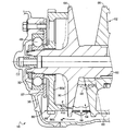
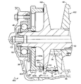
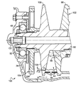
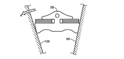
- FIG. 1 is a skeleton diagram of a vehicular power transmission apparatus to which the present invention is preferably applied. It is sectional drawing which shows the actual structure of the continuously variable transmission of one Example of this invention among the power transmission devices for vehicles of FIG. It is sectional drawing which expands and shows a secondary pulley and the one end part of an output shaft among the continuously variable transmission of FIG. It is sectional drawing which expands and shows a secondary pulley and a parking gear among the continuously variable transmission of the other Example of this invention. It is sectional drawing which expands and shows a secondary pulley and a parking gear among the continuously variable transmission of the other Example of this invention.
- FIG. 1 is a skeleton diagram of a vehicle power transmission device 10 to which the present invention is preferably applied.
- a vehicular power transmission device 10 is for an FF (front engine / front drive) vehicle and is connected to an engine 12 well known as a vehicular drive source.
- This vehicle power transmission device 10 uses a torque converter 14 that is well known as a fluid transmission device that transmits the torque of the engine 12 using a fluid as a medium, and the rotational direction of the torque transmitted from the torque converter 14 in order to advance the vehicle.
- the forward / reverse switching device 16 that switches between the rotation direction of the vehicle and the reverse rotation direction for reverse traveling of the vehicle, and the torque transmitted through the forward / reverse switching device 16 is converted into torque according to the load.
- a well-known so-called bevel gear type differential gear device 24 is provided which transmits the generated torque to the pair of left and right wheels 22 while allowing the rotational difference therebetween.
- the pump impeller 26 of the torque converter 14 is provided with a mechanical oil pump 28 that generates, for example, hydraulic pressure used for shift control of the continuously variable transmission 18 and forward / reverse switching control of the forward / reverse switching device 16. Yes.
- the forward / reverse switching device 16 is connected to a sun gear 32 that is connected to the turbine shaft 30 of the torque converter 14 so that power can be transmitted, and is connected to an input shaft 34 of the continuously variable transmission 18, and a forward clutch C is connected to the turbine shaft 30.
- the vehicle 36 is selectively connected via a reverse brake B to a transaxle case 38 that accommodates a carrier 36 that is selectively connected to the vehicle, and a forward / reverse switching device 16, a continuously variable transmission 18, a differential gear device 24, and the like.
- a double pinion type planetary gear device including a ring gear 40 connected to the main body is mainly constituted.
- Both the forward clutch C and the reverse brake B are hydraulic friction engagement devices that are frictionally engaged when oil pressure is supplied from the oil pump 28.
- the forward clutch C is engaged and the reverse brake B is released, whereby the planetary gear device is brought into an integral rotation state and a forward power transmission path is established. It is like that.
- the forward power transmission path is established, the torque transmitted from the torque converter 14 is transmitted to the continuously variable transmission 18 in the same rotational direction.
- the reverse brake B is engaged and the forward clutch C is released, whereby the planetary gear device is brought into the input / output reverse rotation state, and the reverse power transmission path is established. It is supposed to be.
- the reverse power transmission path is established, the torque transmitted from the torque converter 14 is transmitted to the continuously variable transmission 18 with its rotational direction reversed. Further, the forward / reverse switching device 16 is brought into a neutral state (blocked state) in which power transmission is blocked by releasing both the forward clutch C and the reverse brake B.
- FIG. 2 is a cross-sectional view showing a configuration of a continuously variable transmission 18 according to an embodiment of the present invention in the vehicle power transmission device 10 of FIG.
- the continuously variable transmission 18 is provided on an outer peripheral side of the input shaft 34, and an input shaft 34 that is rotatably supported by a transaxle case 38 around a shaft center C ⁇ b> 1 via a pair of bearings 42.
- the secondary pulley (groove width variable pulley) 52 provided on the outer peripheral side of the shaft 34 and the primary pulley 46 and the V-groove 54 of the secondary pulley 52 are wound around the pulley 34 so that power is transmitted by friction between the pulleys.
- a known endless annular transmission belt 56 is used to transmit a known endless annular transmission belt 56.
- the primary pulley 46 is relatively non-rotatable with respect to the input shaft 34 so that the V groove 54 is formed between the fixed sheave 58 fixed on the outer peripheral side of the input shaft 34 and the fixed sheave 58, and the input thereof
- the movable sheave 60 provided so as to be relatively movable in the direction of the axis C1 of the shaft 34, and the movable sheave 60 and the fixed sheave 58 are moved closer to each other by moving the movable sheave 60 in the direction of the axis C1 according to the supplied hydraulic pressure.
- a hydraulic actuator 62 that changes the groove width of the V-groove 54 by being separated.
- the secondary pulley 52 is not relatively rotatable with respect to the output shaft 50 so as to form the V groove 54 between the fixed sheave 64 fixed to the outer peripheral side of the output shaft 50 and the fixed sheave 64.
- a movable sheave 66 provided so as to be relatively movable in the direction of the axis C2 of the output shaft 50, and the movable sheave 66 and the fixed sheave 64 are moved in the direction of the axis C2 in accordance with the supplied hydraulic pressure.
- a hydraulic actuator 68 that changes the groove width of the V-groove 54 by approaching or separating.
- the hydraulic actuator 68 of the secondary pulley 52 is a single piston type, whereas the hydraulic actuator 62 of the primary pulley 46 is a double piston type, and the hydraulic pressure of the secondary pulley 52 is
- the actuator 68 is provided with a coil spring 70 that always urges the movable sheave 66 toward the fixed sheave 64 side, whereas the hydraulic actuator 62 of the primary pulley 46 is not provided with a spring as described above. Is a variable groove width pulley having a similar structure.
- the secondary pulley 52 is demonstrated in detail on behalf of the primary pulley 46 and the secondary pulley 52. FIG.
- the fixed sheave 64 is an annular plate-like member that protrudes from the outer peripheral surface of the output shaft 50 to the outer peripheral side and is provided integrally with the output shaft 50.
- the fixed sheave 64 is formed with a tapered surface 72 that is separated from the movable sheave 60 toward the outer peripheral side on the surface facing the movable sheave 60.
- the movable sheave 66 is engaged with the output shaft 50 by a ball spline method so as to be relatively movable in the direction of the axis C2 and non-rotatably around the axis C2, and to fix the cylindrical part 66a.
- a circular plate-like member that is integrally provided so as to protrude from one end portion on the sheave 64 side toward the outer peripheral side, and has a tapered surface 74 that is separated from the fixed sheave 64 toward the outer peripheral side on the surface facing the fixed sheave 64. It has a plate portion 66b and an outer cylindrical portion 66c projecting in the direction of the axis C2 from the outer peripheral portion of the disk portion 66b toward the opposite side of the fixed sheave 64.
- the tapered surface 74 and the tapered surface 72 of the fixed sheave 64 form a V-shaped V groove 54.
- the hydraulic actuator 68 has an inner peripheral wall portion having an inner peripheral portion sandwiched between a stepped end surface of one end portion thereof and the bearing 48 at one end portion of the output shaft 50 opposite to the fixed sheave 64 with respect to the movable sheave 66.
- a cylinder member 76 having an outer peripheral wall portion 76 c that protrudes on the outer peripheral side and slides through an oil seal with respect to the inner peripheral surface of the outer cylindrical portion 66 c of the movable sheave 66 is provided.
- a hydraulic chamber 78 is formed in a space that is oil-tightly surrounded by the cylinder member 76, the movable sheave 66, and the output shaft 50.
- the hydraulic chamber 78 includes a first oil passage 80 and an output shaft 50 that are formed in the transaxle case 38 and are supplied with hydraulic pressure via a hydraulic control device (not shown) that regulates the hydraulic pressure generated by the oil pump 28.
- Hydraulic pressure is supplied through a second oil passage 82 formed on the inner peripheral side and a third oil passage 84 formed through the output shaft 50 in the radial direction.
- the coil spring 70 is located between the stepped end surface formed on the outer peripheral surface of the inner cylindrical portion 66a of the movable sheave 66 and the stepped end surface formed on the inner peripheral surface of the cylindrical portion 76b of the cylinder member 76. Is provided.
- a movable sheave 66 approaches or separates from the fixed sheave 64 in the direction of the axis C1 in accordance with the hydraulic pressure supplied to the hydraulic chamber 78, so that the width of the V groove 54 changes.
- a movable sheave 66 indicated by a solid line below the axis C ⁇ b> 2 shows a state in which the V groove 54 formed between the fixed sheave 64 and the minimum sheave has a minimum width. In this state, the engagement diameter of the transmission belt 56 is maximized.
- a movable sheave 66 indicated by a solid line on the upper side of the axis C2 and indicated by a two-dot chain line on the lower side shows a state in which the V groove 54 formed between the fixed sheave 64 and the fixed sheave 64 has a maximum width. In this state, the diameter of the transmission belt 56 is minimized.
- FIG. 3 is an enlarged cross-sectional view of the secondary pulley 52 and one end of the output shaft 50 in the continuously variable transmission 18 of FIG.
- a parking gear 86 is fixed between the secondary pulley 52 of the output shaft 50 and the bearing 48 to fix the output shaft 50 so as not to rotate.
- the parking gear 86 is fixed to the fixed sheave 64 on the side opposite to the movable sheave 66 by a disc-like main body 86a fixed by, for example, spline fitting to the output shaft 50, and the main body 86a.
- the sheave 64 has an annular protrusion 86b that protrudes toward the wall surface opposite to the movable sheave 66, that is, the back surface 90, and abuts at a radial position corresponding to the maximum engagement diameter of the transmission belt 56 in the back surface 90. Yes.
- outer peripheral teeth 88 that can be engaged with a parking pole (not shown) provided on a non-rotating member such as the transaxle case 38 are formed.
- the output shaft 50 is fixed to be non-rotatable about the axis C2 when the parking pole is engaged with the outer peripheral teeth 88 of the parking gear 86.
- the parking gear 86 has a main body portion 86a fitted into one end portion of the output shaft 50, for example, in an interference fit or a clearance fit, and is sandwiched between the bearing 48 and the fixed sheave 64 in the direction of the axis C2.
- the nut 92 screwed into the shaft end portion of the output shaft 50 is tightened on the opposite side of the bearing 48 from the bearing gear 86, so that the shaft 48 moves in the direction of the axis C ⁇ b> 2 between the bearing 48 and the fixed sheave 64. It is pinched.
- a pressing force (preload) from the annular protrusion 86b of the parking gear 86 toward the fixed sheave 64 is given to the fixed sheave 64 in advance.
- This pressing force is adjusted to a predetermined value by adjusting the tightening torque according to the relationship between the tightening torque of the nut 92 and the pressing force, which are experimentally determined in advance.
- the predetermined value is set as large as possible within a range in which the fixed sheave 64 is not deformed to the movable sheave 66 side.
- the annular protrusion 86b of the parking gear 86 of the present embodiment is different from the annular protrusion 104b of the conventional parking gear 104 shown in FIG.
- the primary hydraulic pressure supplied to the hydraulic actuator 62 of the primary pulley 46 is regulated by the hydraulic control device and supplied to the hydraulic actuator 68 of the secondary pulley 52.
- the secondary hydraulic pressure is controlled by the hydraulic control device, the groove widths of the V grooves 54 of the primary pulley 46 and the secondary pulley 52 change, and the clamping pressure with respect to the transmission belt 56 is adjusted.
- the groove width of the V groove 54 of the primary pulley 46 and the secondary pulley 52 changes, the engagement diameter of the transmission belt 56 changes, and the rotational speed ratio (speed change) between the input shaft 34 and the output shaft 50 changes. Ratio) changes steplessly.
- the transmission belt 56 indicated by a solid line has a minimum engagement diameter at the primary pulley 46 and a maximum engagement diameter at the secondary pulley 52.
- the transmission gear ratio of the continuously variable transmission 18 is set to the maximum transmission gear ratio.
- the transmission belt 56 indicated by a two-dot chain line has a maximum engagement diameter at the primary pulley 46 and a minimum engagement diameter at the secondary pulley 52, and the belt type continuously variable transmission 18. The state where the gear ratio is set to the minimum gear ratio is shown.
- the fixed sheave 64 and the movable sheave 66 of the secondary pulley 52 receive a reaction force from the transmission belt 56 while applying a clamping pressure in the direction of the axis C2 to the transmission belt 56.
- the fixed sheave 64 has a base portion, that is, an inner peripheral portion of the fixed sheave 64 as a fulcrum, due to the axial reaction force Fc2 of the axial center C2 component of the reaction force F received from the transmission belt 56
- a moment M is applied to tilt the fixed sheave 64 to the side opposite to the movable sheave 66.
- the reaction force and the moment M are maximized when the engagement diameter of the transmission belt 56 is maximized as shown by the solid line in FIG.
- the parking gear 86 is in contact with the back surface 90 of the fixed sheave 64 on the side where the fixed sheave 64 is about to fall due to the moment M.
- the pressing force acting in the direction opposite to the axial reaction force Fc2 is applied to the fixed sheave 64 in advance.
- the pressing force is applied to a position of the back surface 90 of the fixed sheave 64 that opposes the operating point of the maximum axial reaction force Fc2 that the fixed sheave 64 receives from the transmission belt 56 in the operating direction. It has become. Therefore, the parking gear 86 of this embodiment functions as a member that supports the fixed sheave 64 so as to resist the axial reaction force Fc2 (bending moment M).
- the secondary pulley (groove width variable pulley) 52 includes a fixed sheave 64 fixed to the outer peripheral surface of the output shaft 50 (one of the input shaft and the output shaft), A movable groove provided on the output shaft 50 so as not to be relatively rotatable about the axis C2 and to be relatively movable in the direction of the axis C2 so as to form a V-groove 54 for sandwiching the transmission belt 56 with the fixed sheave 64.
- the transmission sheave 64 is clamped between the stationary sheave 64 and the movable sheave 66 so that the stationary sheave 64 is axially oriented in the direction of the axis C2 from the transmission belt 56. Even if the reaction force Fc2 is received, the transmission of the fixed sheave 64 is performed by the parking gear 86 in which only a relatively simple change has been made to form an annular protrusion 86b with respect to what is conventionally fixed to the output shaft 50. Since the outer peripheral side of the rear surface 90 on the side opposite to the belt 56 is supported from the minimum engagement diameter of the transmission belt 56, it is possible to suppress the falling of the fixed sheave 64 without adding parts and with a relatively simple configuration. it can.
- the annular protrusion 86 b of the parking gear 86 abuts on the radial position corresponding to the maximum engagement diameter of the transmission belt 56 on the back surface 90 of the fixed sheave 64.
- the fixed sheave 64 receives the maximum axial reaction force Fc2 in the axial center C2 direction from the transmission belt 56 by sandwiching the transmission belt 56 positioned at the maximum engagement diameter between the fixed sheave 64 and the movable sheave 66.
- the parking gear 86 is tightened with the nut 92 screwed to the shaft end portion of the output shaft 50 and tightened with the fixed sheave 64 in the axial center C2 direction.
- the fixed sheave 64 is preliminarily applied with a pressing force (preload) from the parking gear 86 to the fixed sheave 64 side in a direction opposite to the axial reaction force Fc2. Even if the axial sheer reaction force Fc2 to the parking gear 86 side acts on the fixed sheave 64, it is possible to suitably suppress the fall.
- the pressing force previously applied from the parking gear 86 to the fixed sheave 64 is as large as possible within a range in which the fixed sheave 64 does not deform toward the movable sheave 66 side. Therefore, the stationary sheave 64 can be prevented from falling down while preventing the fixed sheave 64 from being deformed to the movable sheave 66 side by the pressing force and lowering the power transmission efficiency.
- FIG. 10 is a sectional view showing the secondary pulley 102 and the parking gear 104 in the conventional continuously variable transmission 100, and corresponds to FIG. 3 of the first embodiment.
- the annular protrusion 104 b has a radial position on the inner peripheral side of the base portion of the fixed sheave 106, that is, the rear surface 108 of the fixed sheave 106, with respect to the minimum engagement diameter of the transmission belt 56. It is in contact with.
- the stationary sheave 106 falls to the opposite side of the movable sheave 66, and as a result, the contact area between the stationary sheave 106 and the transmission belt 56 decreases and the power transmission efficiency decreases.
- the conventional continuously variable transmission 100 has been dealt with by increasing the thickness of the fixed sheave 106 in the direction of the axis C2 to increase the strength. However, this increases the material cost of the fixed sheave 106. As a result, the manufacturing cost of the continuously variable transmission 100 increases, and the weight of the continuously variable transmission 100 increases.
- the continuously variable transmission 18 of the present embodiment since the back surface 90 of the fixed sheave 64 is supported by the annular protrusion 86b of the parking gear 86, the conventional fixed shown by a two-dot chain line in FIG. Even if the thickness of the fixed sheave 64 in the direction of the axis C2 is smaller than that of the sheave 106, the fixed sheave 64 can be prevented from falling. Therefore, compared to the conventional continuously variable transmission 100, the material cost of the fixed sheave 64 is reduced, the manufacturing cost of the continuously variable transmission 18 is reduced, and the weight of the continuously variable transmission 18 is reduced.
- FIG. 4 is an enlarged sectional view showing the secondary pulley 202 and the parking gear 204 in the continuously variable transmission 200 according to another embodiment of the present invention.
- the fixed sheave 206 of the secondary pulley 202 includes an annular fitting portion 206 a that protrudes from the outer peripheral portion of the back surface 208 opposite to the movable sheave 66 toward the parking gear 204.
- the parking gear 204 is an annular plate-shaped main body portion 204 a fixed to the outer peripheral surface of the output shaft 50, and protrudes from the main body portion 204 a toward the fixed sheave 206. And an annular protrusion 204b fitted in 206a and engaged in the radial direction.
- the parking gear 204 has a main body portion 204a fitted into one end portion of the output shaft 50, for example, in an interference fit or a clearance fit, and is sandwiched between the bearing 48 and the fixed sheave 206 in the axial center C2 direction.
- the nut 92 screwed to the shaft end portion of the output shaft 50 is tightened on the opposite side of the parking gear 204 with respect to the bearing 48, so that the bearing 48 and the fixed sheave 206 are moved in the axial center C2 direction. It is pinched. As a result, a pressing force (preload) from the parking gear 204 toward the fixed sheave 206 is applied to the fixed sheave 206.
- This pressing force is adjusted to a predetermined value by adjusting the tightening torque according to the relationship between the tightening torque of the nut 92 and the pressing force, which are experimentally determined in advance.
- the predetermined value is set as large as possible within a range in which the fixed sheave 206 is not deformed to the movable sheave 66 side.
- the pressing force is applied in advance from the parking gear 204 to the fixed sheave 206 by tightening the nut 92 screwed to the shaft end of the output shaft 50.
- the fixed sheave 206 is opposite to the movable sheave 66 with the base portion, that is, the inner peripheral portion of the fixed sheave 206 as a fulcrum by the axial reaction force Fc2 received from the transmission belt 56.
- a moment M that tends to tilt to the side acts on the fixed sheave 206.
- the parking gear 204 is in contact with the back surface 208 of the fixed sheave 206 on the side where the fixed sheave 206 is about to fall due to the moment M.
- the pressing force acting in the direction opposite to the axial reaction force Fc2 is applied to the fixed sheave 206 in advance.
- the pressing force is applied to a position of the back surface 208 of the fixed sheave 206 that opposes the operating point of the maximum axial reaction force Fc2 that the fixed sheave 206 receives from the transmission belt 56 in the direction of the operation. It has become. Therefore, the parking gear 204 of this embodiment functions as a member that supports the fixed sheave 206 so as to resist the axial reaction force Fc2 (bending moment M).
- the parking gear 204 of the present embodiment is a member that supports the stationary sheave 206 in the radial direction so that the stationary sheave 206 does not fall against the radial reaction force Fr of the direction component orthogonal to the axis C2 of the reaction force F. Function.
- a disc-shaped main body portion 204a fixed to the output shaft 50 on the opposite side of the fixed sheave 206 from the movable sheave 66, a disc-shaped main body portion 204a fixed to the output shaft 50, and the main body portion 204a. Parking that has an annular protrusion 204b that protrudes toward the wall surface opposite to the movable sheave 66 of the fixed sheave 206, that is, the rear surface 208, and abuts at the radial position corresponding to the maximum engagement diameter of the transmission belt 56 in the rear surface 208.
- the fixed sheave 206 Since the gear 204 is provided, the fixed sheave 206 has the maximum in the direction of the axis C2 from the transmission belt 56 by sandwiching the transmission belt 56 positioned at the maximum engagement diameter between the fixed sheave 206 and the movable sheave 66. Even if the axial reaction force Fc2 is received, the axial direction of the maximum axial reaction force Fc2 on the back surface 208 of the fixed sheave 206 is reduced. Since the position of the reaction direction of the reaction force Fc2 is supported by the annular protrusion 204b of the parking gear 204, the stationary sheave 206 can be tilted without adding any parts and with a relatively simple configuration as in the first embodiment. Can be suppressed.
- the annular protrusion 204b of the parking gear 204 is in the annular fitting portion 206a that protrudes from the outer peripheral portion of the back surface 208 of the fixed sheave 206 toward the parking gear 204. Since the transmission belt 56 is clamped between the fixed sheave 206 and the movable sheave 66, the fixed sheave 206 is orthogonal to the axis C2 received from the transmission belt 56.
- the radial reaction force Fr in the direction is transmitted to the output shaft 50 through the fixed sheave 206 and the parking gear 204, and is dispersed in the direction of the axis C2 as compared with the case where the radial reaction force Fr is transmitted only through the fixed sheave 206. Therefore, the bending of the output shaft 50 due to the radial reaction force Fr can be suitably suppressed. Even if the diameter dimension of the output shaft 50 is reduced, it is possible to ensure a bending rigidity equal to or higher than that when the radial reaction force Fr is transmitted only through the fixed sheave 206. Weight can be reduced.
- FIG. 5 is an enlarged sectional view showing the secondary pulley 302 and the parking gear 304 in the continuously variable transmission 300 according to another embodiment of the present invention.
- the fixed sheave 306 of the secondary pulley 302 is formed with a stepped end surface 310 on the inner peripheral portion of the back surface 308 opposite to the movable sheave 66.
- the parking gear 304 includes a main body 304a and an annular protrusion 304b similar to the main body 86a and the annular protrusion 86b of the parking gear 86 of the first embodiment, and an inner peripheral side of the annular protrusion 304b of the main body 304a.
- a stopper portion 304c protruding toward the stepped end surface 310 of the back surface 308.
- the stopper portion 304c comes into contact with the stepped end surface 310 of the back surface 308, and the annular projection 304b.
- the application of the pressing force to the fixed sheave 306 is limited.
- the predetermined value is set as large as possible within a range in which the fixed sheave 306 is not deformed to the movable sheave 66 side.
- FIG. 5 shows a state in which a gap in the direction of the axis C2 is formed between the stopper portion 304c and the stepped end surface 310. This indicates a stage in the middle of assembly, Actually, the stopper portion 304c and the stepped end surface 310 are brought into contact with each other in the axial center C2 direction, and a predetermined pressing force of a predetermined value is applied from the annular protrusion 304b to the fixed sheave 306 as described above.
- the parking gear 304 is a member that supports the fixed sheave 306 so as to resist the axial reaction force Fc2 (bending moment M). Function.
- the fixed sheave 306 has a relatively simple configuration without adding parts. The fall can be suppressed.
- the parking gear 304 is provided with a stopper portion 304c that protrudes from the inner peripheral side of the annular protrusion 304b of the main body portion 304a toward the stepped end surface 310 of the back surface 308.
- the stopper portion 304c comes into contact with the stepped end surface 310 of the back surface 308, and the annular projection Since the application of the pressing force from 304b to the fixed sheave 306 is limited, if the parking gear 304 is fixed at a position where the stopper portion 304c abuts the stepped end surface 310 of the back surface 308, the parking gear 304 is fixed to the fixed sheave 306 beforehand. Since the applied pressing force (preload) can be made uniform, the above pressing force can be adjusted easily. . That is, the pressing force can be adjusted by, for example, human work without using a special device such as a preload adjusting device.
- the parking gear 304 is clamped in the direction of the axis C2 with the fixed sheave 306 by tightening the nut 92 screwed to the shaft end portion of the output shaft 50 to which the parking gear 304 is fixed.
- the parking gear 304 is Since the pressing force to the fixed sheave 306 can be given a predetermined value, the pressing force can be easily adjusted.
- FIG. 6 is an enlarged sectional view showing the secondary pulley 402 and the parking gear 404 in the continuously variable transmission 400 according to another embodiment of the present invention.
- the fixed sheave 406 of the secondary pulley 402 includes an outer peripheral portion of the back surface 408 opposite to the movable sheave 66 and including a radial position corresponding to the maximum engagement diameter of the transmission belt 56.
- a plurality of first spline teeth (engagement teeth) 410 extending radially about the axis C2 are formed continuously in the circumferential direction.
- the first spline teeth 410 of this embodiment are involute splines, for example, but may be other splines.
- the parking gear 404 protrudes toward the back surface 408 of the fixed sheave 406 from the main body portion 404a similar to the main body portion 86a of the parking gear 86 of the first embodiment. And an annular protrusion 404b that contacts the fixed sheave 406 at a radial position corresponding to the maximum engagement diameter.
- the parking gear 404 is formed in a fixed sheave via a plurality of second spline teeth 412 that are respectively formed radially at the front end of the annular protrusion 404b and centered on the axis C2 and mesh with the plurality of first spline teeth 410, respectively.
- 406 is in contact with the axis C2 and engaged in the circumferential direction.
- the parking gear 404 is a member that supports the fixed sheave 406 so as to resist the axial reaction force Fc2 (bending moment M). Function.
- the engaging portion between the first spline teeth 410 and the second spline teeth 412 is used.
- the torque of the output shaft 50 is transmitted to the parking gear 404.
- the length L in the axial center C2 direction of the spline fitting portion between the outer peripheral surface of the output shaft 50 and the inner peripheral surface of the parking gear 404 of this embodiment is shortened by the length L1.
- the fixed sheave 406 can be formed without adding parts and with a relatively simple configuration as in the first embodiment. The fall can be suppressed.
- the annular protrusion 404b of the parking gear 404 has a wall surface opposite to the movable sheave 66 of the fixed sheave 406, that is, the back surface 408 via the second spline teeth 412. Since the first spline teeth (engagement teeth) 410 formed in the outer peripheral portion of the parking gear 404 are engaged in the circumferential direction, the parking gear 404 is fixed to the outer peripheral teeth 88 of the parking gear 404 in order to fix the output shaft 50 in a non-rotatable manner.
- the reaction force that is, the torque that the parking gear 404 receives from the parking pole due to the engagement of the pawl is the engaging portion between the parking gear 404 and the fixed sheave 406 in addition to the engaging portion between the parking gear 404 and the output shaft 50. Therefore, even if the length L of the engagement portion between the parking gear 404 and the output shaft 50 is shortened in the direction of the axis C2, the parkin The strength to resist the reaction force received from the pole can be secured to a conventional equal to or higher. Further, the engaging portion between the first spline teeth 410 and the second spline teeth 412 is provided on the outer peripheral side than the spline fitting portion between the outer peripheral surface of the output shaft 50 and the inner peripheral surface of the parking gear 404.
- the strength for resisting the reaction force received from the parking pole can be suitably ensured to be equal to or higher than the conventional one. Therefore, the molding cost of the spline fitting portion between the outer peripheral surface of the output shaft 50 and the inner peripheral surface of the parking gear 404 is reduced, and the length of the output shaft 50 is shortened by the shortened length L1 of the spline fitting portion. Therefore, the manufacturing cost of the continuously variable transmission 400 can be reduced.
- FIG. 7 is an enlarged cross-sectional view of the secondary pulley 502 and the parking gear 504 in the continuously variable transmission 500 according to another embodiment of the present invention.
- the fixed sheave 506 of the secondary pulley 502 includes an annular fitting portion 506 a protruding from the outer peripheral portion of the back surface 508 opposite to the movable sheave 66 toward the fixed sheave 506,
- a plurality of first spline teeth (engagement teeth) 510 extending in the axial center C2 direction are formed on the inner peripheral surface of the annular fitting portion 506a in a circumferential direction.
- the first spline teeth 510 of the present embodiment are, for example, involute splines, but may be other splines.
- the parking gear 504 protrudes from the main body 504a toward the rear surface 508 of the fixed sheave 506, and the rear surface of the main body 504a.
- the main body 504a has an inner peripheral surface fitted on the outer peripheral surface of the output shaft 50.
- An annular protrusion 504 b that abuts against the fixed sheave 506 at a radial position corresponding to the maximum engagement diameter of the transmission belt 56 out of 508.
- the parking gear 504 is fixed to the fixed sheave via a plurality of second spline teeth 512 that extend in the direction of the axis C2 on the outer peripheral surface of the tip of the annular protrusion 504b and mesh with the plurality of first spline teeth 510, respectively. 506 is engaged in the circumferential direction.
- the parking gear 504 is a member that supports the fixed sheave 506 so as to resist the axial reaction force Fc2 (bending moment M). Function. Even if the parking gear 504 receives a moment that tends to fall to the opposite side of the movable sheave 66 due to the reaction force F that the fixed sheave 506 receives from the transmission belt 56, the annular protrusion 204 b of the parking gear 504 does not move. The annular fitting portion 506a of the fixed sheave 206 is supported in the radial direction on the side to be tilted.
- the parking gear 504 of this embodiment is a member that supports the stationary sheave 506 in the radial direction so that the stationary sheave 506 does not fall against the radial reaction force Fr of the directional component orthogonal to the axis C2 of the reaction force F. Function.
- the torque of the output shaft 50 is transmitted to the parking gear 504 through the engaging portion between the first spline teeth 510 and the second spline teeth 512.
- the engagement portion between the first spline teeth 410 and the second spline teeth 412 is a spline fitting portion between the outer peripheral surface of the output shaft 50 and the inner peripheral surface of the parking gear 104 formed in the conventional one shown in FIG.
- the parking pawl is engaged with the outer peripheral teeth 88 of the parking gear 504 in order to fix the output shaft 50 in a non-rotatable manner, so that the parking gear 504 receives the reaction force received from the parking pawl.
- the strength to withstand is ensured to be equal to or higher than the conventional one.
- the configuration other than the above is the same as that of the first embodiment, and according to the continuously variable transmission 500 of the present embodiment, as in the first embodiment, the fixed sheave 506 can be formed without adding parts and with a relatively simple configuration. The fall can be suppressed.
- the annular protrusion 504b of the parking gear 504 has a wall surface on the opposite side to the movable sheave 66 of the fixed sheave 506, that is, the back surface 508 via the second spline teeth 512. Since the first spline teeth (engagement teeth) 510 formed on the outer peripheral portion of the outer peripheral portion are engaged in the circumferential direction, the conventionally provided spline fitting portion between the parking gear 504 and the output shaft 50 is eliminated. be able to.
- the engagement portion between the first spline teeth 410 and the second spline teeth 412 is a spline fitting between the outer peripheral surface of the output shaft 50 and the inner peripheral surface of the parking gear 104 formed in the conventional one shown in FIG. Since the parking pawl is engaged with the outer peripheral teeth 88 of the parking gear 504 in order to fix the output shaft 50 so as not to rotate, the reaction force received by the parking gear 504 from the parking pawl is provided. The strength for resisting the above can be ensured to be equal to or higher than the conventional one.
- annular protrusion 204b of the parking gear 504 supports the annular fitting portion 506a of the fixed sheave 206 in the radial direction, the bending rigidity of the output shaft 50 and the entire member fixed thereto is improved. Enhanced. Therefore, even if the diameter of the output shaft 50 is reduced, it is possible to ensure a bending rigidity equal to or higher than the conventional one.
- FIG. 8 is an enlarged cross-sectional view of the secondary pulley 52 and the parking gear 602 in the continuously variable transmission 600 according to another embodiment of the present invention.
- the parking gear 602 includes a main body 602 a similar to the main body 86 a of the parking gear 86 according to the first embodiment, and the transmission belt 56 of the back surface 90 of the fixed sheave 64 from the outer periphery of the main body 602 a. It is inserted into an annular O-ring groove 604 formed on a surface opposite to the annular protrusion 602b projecting toward the radial position corresponding to the maximum hook diameter of the annular protrusion 602b and the back surface 90 of the annular protrusion 602b.
- the O-ring 606 is provided.
- the O-ring 606 is made of, for example, an oil-resistant synthetic rubber, and is disposed in close contact with the bottom surface and the back surface 90 of the O-ring groove 604.
- An annular protrusion 602 b of the parking gear 602 is brought into contact with the fixed sheave 64 via an O-ring 606.
- a hydraulic chamber 608 is formed on the inner peripheral side of the annular protrusion 602b.
- the hydraulic chamber 608 includes an annular space surrounded by the main body 602a and the annular protrusion 602b of the parking gear 602 and the fixed sheave 64. Yes.
- the hydraulic chamber 608 is supplied with a predetermined hydraulic pressure from the second oil passage 82 through a hydraulic supply hole 610 pierced radially from the second oil passage 82 in the output shaft 55 on the inner peripheral side of the hydraulic chamber 608.
- a pressing force that presses the wall surface of the fixed sheave 64 opposite to the movable sheave 66, that is, the back surface 90, toward the movable sheave 66 is generated.
- the hydraulic pressure supplied to the hydraulic chamber 608 is a part of the secondary hydraulic pressure that is pressure-controlled by the hydraulic control device and supplied to the hydraulic actuator 68 shown in FIG.
- the transmission belt 56 is clamped between the fixed sheave 64 and the movable sheave 66, whereby the fixed sheave 64 is axially centered in the direction of the axis C2 from the transmission belt 56.
- a moment M that attempts to tilt the fixed sheave 64 to the opposite side of the movable sheave 66 acts on the fixed sheave 64 with the base portion, that is, the inner periphery of the fixed sheave 64 as a fulcrum.
- the pressing force generated by supplying the secondary hydraulic pressure to the hydraulic chamber 608 is against the back surface 90 of the fixed sheave 64 so as to resist the axial reaction force Fc2 (bending moment M). Therefore, it acts in the opposite direction to the axial reaction force Fc2.
- a disk-shaped main body portion 602a fixed to the output shaft 50 on the opposite side of the fixed sheave 64 from the movable sheave 66, a disk-shaped main body portion 602a fixed to the output shaft 50, and the main body portion 602a.
- An annular protrusion 602b that protrudes from the outer peripheral portion toward the radial position corresponding to the maximum engagement diameter of the transmission belt 56 in the back surface 90 of the fixed sheave 64, and a surface that faces the back surface 90 of the annular protrusion 602b.
- a parking gear 602 having an O-ring 606 fitted in a formed annular O-ring groove 604, and a main body 602 a and an annular protrusion 602 b of the parking gear 602 and a fixed sheave 64.
- the movable sheave 66 of the fixed sheave 64 is formed by supplying a secondary hydraulic pressure that is formed by a space surrounded by oil tightness and is pressure-controlled by a hydraulic control device. Is provided with a hydraulic chamber 608 that generates an oil pressure that presses the opposite wall surface, that is, the back surface 90 toward the movable sheave 66, so that the transmission belt 56 is clamped between the fixed sheave 64 and the movable sheave 66. Even when the fixed sheave 64 receives the axial reaction force Fc2 in the direction of the axial center C2 from the transmission belt 56, the parking gear 602 and the fixed sheave are only relatively simple changes to those conventionally used.
- the pressing force generated in the formed hydraulic chamber 608 acts on the back surface 90 of the fixed sheave 64 so as to resist the axial reaction force Fc2, so that no additional parts are required and the structure is relatively simple. The falling of the fixed sheave 64 can be suppressed.
- FIG. 9 is an enlarged sectional view showing the secondary pulley 702 and the parking gear 602 in the continuously variable transmission 700 according to another embodiment of the present invention.
- the fixed sheave 704 of the secondary pulley 702 includes an annular fitting portion 704 a that protrudes toward the parking gear 602 side from the wall surface opposite to the movable sheave 66, that is, from the outer peripheral portion of the back surface 706. .
- the annular protrusion 602b of the parking gear 602 is fitted into the annular fitting portion 704a of the fixed sheave 704 and engaged in the radial direction.
- the hydraulic chamber 608 is supplied with a predetermined hydraulic pressure from the second oil passage 82 through a hydraulic supply hole 610 that is radially penetrated from the second oil passage 82 in the output shaft 55 on the inner peripheral side of the hydraulic chamber 608.
- a pressing force for pressing the back surface 706 of the fixed sheave 64 toward the movable sheave 66 is generated.
- the hydraulic pressure supplied to the hydraulic chamber 608 is a part of the secondary hydraulic pressure that is pressure-controlled by the hydraulic control device and supplied to the hydraulic actuator 68 shown in FIG.
- the transmission belt 56 is clamped between the fixed sheave 704 and the movable sheave 66, whereby the fixed sheave 704 is axially centered in the direction of the axis C2 from the transmission belt 56.
- a moment M that tries to tilt the fixed sheave 704 to the opposite side of the movable sheave 66 acts on the fixed sheave 704 with the base portion, that is, the inner periphery of the fixed sheave 704 as a fulcrum.
- the pressing force generated by supplying the secondary hydraulic pressure to the hydraulic chamber 608 is against the back surface 706 of the fixed sheave 704 so as to resist the axial reaction force Fc2 (bending moment M). Therefore, it acts in the opposite direction to the axial reaction force Fc2.
- the parking gear 602 of the present embodiment is a member that supports the stationary sheave 704 in the radial direction so that the stationary sheave 704 does not fall against the radial reaction force Fr of the direction component orthogonal to the axis C2 of the reaction force F. Function.
- the space formed by the main body 602a and the annular protrusion 602b of the parking gear 604 and the fixed sheave 64 is oil-tightly enclosed, and pressure regulation is controlled by the hydraulic control device.
- a hydraulic chamber 608 that generates hydraulic pressure that presses the wall surface of the fixed sheave 704 opposite to the movable sheave 66, that is, the back surface 706, toward the movable sheave 66 is provided.
- the annular protrusion 602b of the parking gear 602 is in the annular fitting portion 704a that protrudes from the outer peripheral portion of the back surface 706 of the fixed sheave 704 toward the parking gear 602. Since the fixed sheave 704 is engaged in the radial direction, even if the stationary sheave 704 receives a moment to fall to the opposite side of the movable sheave 66 due to the reaction force F received from the transmission belt 56, Since the inner peripheral surface of the annular fitting portion 704a of the fixed sheave 704 is supported in the radial direction by the annular protrusion 602b of the parking gear 602, the falling of the fixed sheave 704 can be suppressed.
- the parking gear 86 (204, 304, 404, 504, 602) is provided on the output shaft 50, but may be provided on the input shaft 34.
- the fixed sheave 64 (206, 306, 406, 506, 704) includes a parking gear 86 (204, 304, 404, 504, 602) and a nut 92 and the fixed sheave 64 (206, 306, 406, 506, 704). ),
- the pressing force from the parking gear 86 to the fixed sheave 64 is applied in advance. However, this pressing force is not necessarily applied. Even when the pressing force is applied, the pressing force may not necessarily be as large as possible as long as the fixed sheave 64 is not deformed to the movable sheave 66 side.
- the parking gear 602 includes an O-ring 606 fitted in an O-ring groove 604 formed on a surface facing the back surface 90 of the annular protrusion 602b.
- the hydraulic chamber 608 includes: The O-ring 606 is disposed in close contact with the bottom surface and the back surface 90 of the O-ring groove 604, and is formed of an oil-tight annular space formed on the inner peripheral side of the annular protrusion 602b.
- another sealing member may be provided to form the hydraulic chamber 608.
- the hydraulic chamber 608 may be formed by joining the annular protrusion 602b of the parking gear 602 and the back surface 90 of the fixed sheave 64 (704) continuously in the circumferential direction without any gap, for example, by welding or the like.
- the parking gear 602 is brought into contact with the fixed sheave 64 (704) via the O-ring 606, but the annular protrusion 602b is brought into contact with the fixed sheave 64 (704). May be. Further, the parking gear 602 is pinched in the direction of the axis C2 between the nut 92 and the fixed sheave 64 (704), so that a pressing force from the parking gear 602 to the fixed sheave 64 (704) is applied in advance. Also good.
- Vehicle continuously variable transmission 34 Input shaft 46: Primary pulley (groove width variable pulley) 50: Output shaft (one of input shaft and output shaft) 52, 202, 302, 402, 502, 702: Secondary pulley (variable groove width pulley) 54: V groove 56: Transmission belt 64, 206, 306, 406, 506, 704: Fixed sheave 66: Movable sheave 86, 204, 304, 404, 504, 602: Parking gear 86a, 204a, 304a, 404a, 504a, 602a: body portion 86b, 204b, 304b, 404b, 504b, 602b: annular projection 304c: stopper portion 90, 208, 308, 408, 508, 706: back surface (wall surface opposite to movable sheave of fixed sheave) 92: Nuts 410, 510: First spline teeth (engagement teeth) 608: Hydraulic chamber
Landscapes
- Engineering & Computer Science (AREA)
- General Engineering & Computer Science (AREA)
- Mechanical Engineering (AREA)
- Transmissions By Endless Flexible Members (AREA)
Abstract
Description
34:入力軸
46:プライマリプーリ(溝幅可変プーリ)
50:出力軸(入力軸および出力軸の一方)
52,202,302,402,502,702:セカンダリプーリ(溝幅可変プーリ)
54:V溝
56:伝動ベルト
64,206,306,406,506,704:固定シーブ
66:可動シーブ
86,204,304,404,504,602:パーキングギヤ
86a,204a,304a,404a,504a,602a:本体部
86b,204b,304b,404b,504b,602b:環状突部
304c:ストッパ部
90,208,308,408,508,706:背面(固定シーブの可動シーブとは反対側の壁面)
92:ナット
410,510:第1スプライン歯(係合歯)
608:油圧室
Claims (8)
- 互いに平行に設けられた入力軸および出力軸と、該入力軸および出力軸の外周側に設けられた一対の溝幅可変プーリと、該一対の溝幅可変プーリのV溝にそれぞれ巻き掛けられた伝動ベルトとを備え、該V溝の溝幅を変化させて該伝動ベルトの掛かり径を変化させることにより変速比を無段階に変化させる車両用ベルト式無段変速機であって、
前記溝幅可変プーリは、前記入力軸および出力軸の一方の外周面に固設された固定シーブと、該固定シーブとの間に前記V溝を形成するように、該一方の軸に相対回転不能且つ該一方の軸の軸心方向に相対移動可能に設けられた可動シーブとを備えるものであり、
前記固定シーブに対して前記可動シーブとは反対側において、前記一方の軸に固設された円板状の本体部と、該本体部から前記固定シーブの前記可動シーブとは反対側の壁面に向けて突き出し、該反対側の壁面のうち前記伝動ベルトの最小掛かり径よりも外周側で当接する環状突部とを有するパーキングギヤが設けられていることを特徴とする車両用ベルト式無段変速機。 - 前記パーキングギヤの環状突部は、前記固定シーブの前記可動シーブとは反対側の壁面のうち、前記伝動ベルトの最大掛かり径に対応する径方向位置に当接することを特徴とする請求項1の車両用ベルト式無段変速機。
- 前記パーキングギヤの環状突部は、前記出力軸に設けられた溝幅可変プーリの固定シーブの前記可動シーブとは反対側の壁面に当接するものであることを特徴とする請求項1または2の車両用ベルト式無段変速機。
- 前記パーキングギヤの環状突部は、前記固定シーブの前記可動シーブとは反対側の壁面の外周部から該パーキングギヤ側に突設された環状嵌合部内に嵌め入れられて径方向に係合されていることを特徴とする請求項1乃至3のいずれか1の車両用ベルト式無段変速機。
- 前記パーキングギヤの環状突部は、前記固定シーブの前記可動シーブとは反対側の壁面の外周部に形成された係合歯と周方向に係合されていることを特徴とする請求項1乃至4のいずれか1の車両用ベルト式無段変速機。
- 前記パーキングギヤは、前記本体部の前記環状突部の内周側から前記固定シーブの前記可動シーブとは反対側の壁面に向けて突設されたストッパ部を備え、前記固定シーブに予め与えられる前記環状突部から該固定シーブへの押圧力が予め定められた所定値に達すると該ストッパ部が前記反対側の壁面に当接して、前記環状突部から固定シーブへの押圧力の付与を制限することを特徴とする請求項1乃至5のいずれか1の車両用ベルト式無段変速機。
- 前記パーキングギヤは、前記一方の軸の軸端部に螺合されたナットによって締め付けられることで前記固定シーブとの間で軸心方向に挟圧されるものであることを特徴とする請求項1乃至6のいずれか1の車両用ベルト式無段変速機。
- 前記パーキングギヤの本体部および環状突部と前記固定シーブとによって油密に囲まれた空間により形成され、所定の油圧が供給されることにより、該固定シーブの前記可動シーブとは反対側の壁面を該可動シーブ側へ押圧する油圧力を発生させる油圧室を備えていることを特徴とする請求項1乃至7のいずれか1の車両用ベルト式無段変速機。
Priority Applications (3)
| Application Number | Priority Date | Filing Date | Title |
|---|---|---|---|
| CN201080065175.0A CN102812267B (zh) | 2010-03-04 | 2010-05-25 | 车辆用带式无级变速器 |
| US13/582,154 US8864610B2 (en) | 2010-03-04 | 2010-05-25 | Belt type continuously variable transmission for vehicle |
| JP2012502956A JP5321730B2 (ja) | 2010-03-04 | 2010-05-25 | 車両用ベルト式無段変速機 |
Applications Claiming Priority (2)
| Application Number | Priority Date | Filing Date | Title |
|---|---|---|---|
| PCT/JP2010/053576 WO2011108107A1 (ja) | 2010-03-04 | 2010-03-04 | 車両用ベルト式無段変速機 |
| JPPCT/JP2010/053576 | 2010-03-04 |
Publications (1)
| Publication Number | Publication Date |
|---|---|
| WO2011108127A1 true WO2011108127A1 (ja) | 2011-09-09 |
Family
ID=44541791
Family Applications (2)
| Application Number | Title | Priority Date | Filing Date |
|---|---|---|---|
| PCT/JP2010/053576 Ceased WO2011108107A1 (ja) | 2010-03-04 | 2010-03-04 | 車両用ベルト式無段変速機 |
| PCT/JP2010/058843 Ceased WO2011108127A1 (ja) | 2010-03-04 | 2010-05-25 | 車両用ベルト式無段変速機 |
Family Applications Before (1)
| Application Number | Title | Priority Date | Filing Date |
|---|---|---|---|
| PCT/JP2010/053576 Ceased WO2011108107A1 (ja) | 2010-03-04 | 2010-03-04 | 車両用ベルト式無段変速機 |
Country Status (4)
| Country | Link |
|---|---|
| US (1) | US8864610B2 (ja) |
| JP (1) | JP5321730B2 (ja) |
| CN (1) | CN102812267B (ja) |
| WO (2) | WO2011108107A1 (ja) |
Families Citing this family (11)
| Publication number | Priority date | Publication date | Assignee | Title |
|---|---|---|---|---|
| JP5704230B2 (ja) * | 2011-03-31 | 2015-04-22 | トヨタ自動車株式会社 | ベルト式無段変速機 |
| US9518640B2 (en) * | 2014-02-07 | 2016-12-13 | Deere & Company | Dry variable speed drive mechanism |
| JP6146347B2 (ja) * | 2014-03-12 | 2017-06-14 | トヨタ自動車株式会社 | 車両用ベルト式無段変速機 |
| US10154178B2 (en) * | 2015-10-15 | 2018-12-11 | Panasonic Intellectual Property Management Co., Ltd. | Imaging apparatus with light shielding plates for blocking incident light on a lens |
| US11125306B2 (en) * | 2017-02-20 | 2021-09-21 | Unipres Corporation | Dividing wall for primary pulley in belt-type continuously variable transmission |
| US20200173524A1 (en) * | 2017-09-28 | 2020-06-04 | Aisin Aw Co., Ltd. | Continuously variable transmission and method for manufacturing the same |
| JP6859915B2 (ja) * | 2017-10-10 | 2021-04-14 | トヨタ自動車株式会社 | 伝動ベルト |
| DE102018106774A1 (de) * | 2018-03-22 | 2019-09-26 | Schaeffler Technologies AG & Co. KG | Kegelscheibenanordnung für ein Kegelscheibenumschlingungsgetriebe mit verschachtelten Komponenten |
| CN112728029B (zh) * | 2020-12-29 | 2023-03-17 | 哈尔滨剑桥学院 | 一种cvt变速器传动机构 |
| US11708903B1 (en) * | 2022-10-20 | 2023-07-25 | Borgwarner, Inc. | Park system integration with chain drive |
| MX2025000837A (es) * | 2024-01-23 | 2025-08-01 | Polaris Inc | Transmision mecanica continuamente variable asistida |
Citations (5)
| Publication number | Priority date | Publication date | Assignee | Title |
|---|---|---|---|---|
| JPH03118347U (ja) * | 1990-03-16 | 1991-12-06 | ||
| JP2004084874A (ja) * | 2002-08-28 | 2004-03-18 | Nissan Motor Co Ltd | ベルト式無段変速装置 |
| JP2005003035A (ja) * | 2003-06-10 | 2005-01-06 | Toyota Motor Corp | ベルト式無段変速機 |
| JP2006105217A (ja) * | 2004-10-01 | 2006-04-20 | Toyota Motor Corp | 車両用ベルト式無段変速機の潤滑装置 |
| JP2008309232A (ja) * | 2007-06-13 | 2008-12-25 | Toyota Motor Corp | ベルト式無段変速機 |
Family Cites Families (27)
| Publication number | Priority date | Publication date | Assignee | Title |
|---|---|---|---|---|
| DE68925680T2 (de) * | 1988-12-10 | 1996-06-27 | Suzuki Motor Co | Stufenlos arbeitendes Kraftfahrzeuggetriebe |
| AU632847B2 (en) | 1989-09-08 | 1993-01-14 | Siegfried Peter | Process for preparing pure monoglycerides, pure diglycerides and/or pure triglycerides |
| DE19857709B4 (de) * | 1997-12-22 | 2006-03-23 | Luk Gs Verwaltungs Kg | Getriebe |
| DE19857710B4 (de) * | 1997-12-22 | 2013-02-21 | Schaeffler Technologies AG & Co. KG | Getriebe |
| DE19909347B4 (de) * | 1998-03-10 | 2012-03-29 | Schaeffler Technologies Gmbh & Co. Kg | Getriebe |
| JP2000170859A (ja) * | 1998-12-08 | 2000-06-23 | Toyota Motor Corp | 無段変速機の可変プーリ装置 |
| US6406390B1 (en) * | 1999-09-24 | 2002-06-18 | Borgwarner Automotive, Inc. | Continuously variable belt drive system |
| US6569043B2 (en) * | 1999-11-29 | 2003-05-27 | Team Industries, Inc. | Clutch with a one-way torque carrying bearing |
| US6561934B2 (en) * | 2000-02-18 | 2003-05-13 | Fuji Jukogyo Kabushiki Kaisha | Oil pressure control for continuously variable transmission |
| JP4752089B2 (ja) | 2000-05-17 | 2011-08-17 | トヨタ自動車株式会社 | ベルト式無段変速機 |
| JP2001330089A (ja) * | 2000-05-22 | 2001-11-30 | Toyota Motor Corp | 巻き掛け伝動装置およびベルト式無段変速機 |
| JP2002106658A (ja) | 2000-10-03 | 2002-04-10 | Fuji Heavy Ind Ltd | ベルト式無段変速装置 |
| ITTO20030041A1 (it) * | 2003-01-24 | 2004-07-25 | Lombardini Srl A Socio Unico | Trasmissione a rapporto variabile con continuita', |
| US20040248679A1 (en) * | 2003-06-03 | 2004-12-09 | Yu-Wen Hsu | Torque limiting device for wheeled vehicle |
| JP4449441B2 (ja) * | 2003-12-09 | 2010-04-14 | トヨタ自動車株式会社 | ベルト式無段変速機 |
| JP4039379B2 (ja) * | 2004-03-23 | 2008-01-30 | トヨタ自動車株式会社 | ベルト式無段変速機 |
| JP2005291319A (ja) * | 2004-03-31 | 2005-10-20 | Jatco Ltd | ベルト式無段変速機 |
| JPWO2006001410A1 (ja) * | 2004-06-28 | 2008-04-17 | ヤマハ発動機株式会社 | 鞍乗型車両用のベルト式無段変速機および鞍乗型車両 |
| ATE487897T1 (de) * | 2004-07-02 | 2010-11-15 | Yamaha Motor Co Ltd | Stufenloses keilriemengetriebe für kleine fahrzeuge und grätschsitz-fahrzeuge |
| US7686715B2 (en) * | 2004-07-08 | 2010-03-30 | Gm Global Technology Operations, Inc. | Hybrid clamping mechanism for belt continuously variable transmission and method of use thereof |
| US20060058128A1 (en) * | 2004-08-24 | 2006-03-16 | Luk Lamellen Und Kupplungsbau Beteiligungs Kg | Belt-driven conical-pulley transmission, method for producing it, and motor vehicle having such a transmission |
| US20060052192A1 (en) * | 2004-08-24 | 2006-03-09 | Luk Lamellen Und Kupplungsbau Beteiligungs Kg | Belt-driven conical-pulley transmission, method for producing it, and motor vehicle having such a transmission |
| JP2007071254A (ja) * | 2005-09-05 | 2007-03-22 | Yamaha Motor Co Ltd | Vベルト式無段変速機及び鞍乗型車両 |
| JP2007170504A (ja) | 2005-12-20 | 2007-07-05 | Toyota Motor Corp | ベルト式無段変速機 |
| JP2008232389A (ja) * | 2007-03-23 | 2008-10-02 | Toyota Motor Corp | ベルト式無段変速機 |
| JP4335941B2 (ja) | 2007-12-21 | 2009-09-30 | 株式会社豊田中央研究所 | ベルト式無段変速機及びそのプーリ |
| WO2011148474A1 (ja) * | 2010-05-26 | 2011-12-01 | トヨタ自動車株式会社 | ベルト式無段変速機 |
-
2010
- 2010-03-04 WO PCT/JP2010/053576 patent/WO2011108107A1/ja not_active Ceased
- 2010-05-25 JP JP2012502956A patent/JP5321730B2/ja not_active Expired - Fee Related
- 2010-05-25 CN CN201080065175.0A patent/CN102812267B/zh not_active Expired - Fee Related
- 2010-05-25 US US13/582,154 patent/US8864610B2/en not_active Expired - Fee Related
- 2010-05-25 WO PCT/JP2010/058843 patent/WO2011108127A1/ja not_active Ceased
Patent Citations (5)
| Publication number | Priority date | Publication date | Assignee | Title |
|---|---|---|---|---|
| JPH03118347U (ja) * | 1990-03-16 | 1991-12-06 | ||
| JP2004084874A (ja) * | 2002-08-28 | 2004-03-18 | Nissan Motor Co Ltd | ベルト式無段変速装置 |
| JP2005003035A (ja) * | 2003-06-10 | 2005-01-06 | Toyota Motor Corp | ベルト式無段変速機 |
| JP2006105217A (ja) * | 2004-10-01 | 2006-04-20 | Toyota Motor Corp | 車両用ベルト式無段変速機の潤滑装置 |
| JP2008309232A (ja) * | 2007-06-13 | 2008-12-25 | Toyota Motor Corp | ベルト式無段変速機 |
Also Published As
| Publication number | Publication date |
|---|---|
| US20130040769A1 (en) | 2013-02-14 |
| JP5321730B2 (ja) | 2013-10-23 |
| CN102812267B (zh) | 2014-11-05 |
| WO2011108107A1 (ja) | 2011-09-09 |
| JPWO2011108127A1 (ja) | 2013-06-20 |
| US8864610B2 (en) | 2014-10-21 |
| CN102812267A (zh) | 2012-12-05 |
Similar Documents
| Publication | Publication Date | Title |
|---|---|---|
| JP5321730B2 (ja) | 車両用ベルト式無段変速機 | |
| US6832974B2 (en) | Planetary gear device for vehicle, having clutch drum provided with retainer ring | |
| WO2020084937A1 (ja) | 車両用の無段変速機 | |
| JP5397552B2 (ja) | 車両用ベルト式無段変速機 | |
| US20190293129A1 (en) | Frictional coupling device of vehicular power transmitting system | |
| AU2011379214B2 (en) | Pulley mechanism for continuously variable belt transmission for vehicle | |
| EP3690284A1 (en) | Vehicle power transmission device | |
| JP2008309292A (ja) | 車両用油圧式摩擦係合装置のスナップリング | |
| JP4583139B2 (ja) | 無段変速機の組立構造および組立方法 | |
| JP6366569B2 (ja) | 無段変速機 | |
| JP2015215065A (ja) | 車両用無段変速機 | |
| JP2008208861A (ja) | ベルト式無段変速機 | |
| JP2010242863A (ja) | ベルト式無段変速機 | |
| JP4894552B2 (ja) | 車両用ベルト式無段変速機 | |
| JP6674243B2 (ja) | 変速機及び支持構造の製造方法 | |
| JP6146347B2 (ja) | 車両用ベルト式無段変速機 | |
| CN104061301B (zh) | 无级变速器 | |
| JP2018071746A (ja) | 車両用無段変速機 | |
| JP2018179222A (ja) | 車両用無段変速機 | |
| JP2010255700A (ja) | 車両用ベルト式無段変速機の溝幅可変プーリ | |
| JP6493346B2 (ja) | 車両用無段変速機 | |
| JP3269419B2 (ja) | ベルト式プーリ装置 | |
| JP2019060354A (ja) | 車両用無段変速機 | |
| JP2017155782A (ja) | 動力伝達機構 | |
| JP6517688B2 (ja) | 動力伝達装置 |
Legal Events
| Date | Code | Title | Description |
|---|---|---|---|
| WWE | Wipo information: entry into national phase |
Ref document number: 201080065175.0 Country of ref document: CN |
|
| 121 | Ep: the epo has been informed by wipo that ep was designated in this application |
Ref document number: 10847024 Country of ref document: EP Kind code of ref document: A1 |
|
| WWE | Wipo information: entry into national phase |
Ref document number: 2012502956 Country of ref document: JP |
|
| NENP | Non-entry into the national phase |
Ref country code: DE |
|
| WWE | Wipo information: entry into national phase |
Ref document number: 13582154 Country of ref document: US |
|
| 122 | Ep: pct application non-entry in european phase |
Ref document number: 10847024 Country of ref document: EP Kind code of ref document: A1 |