WO2011081392A2 - 표면특성이 우수한 열간 프레스용 아연도금강판, 이를 이용한 열간 프레스 성형부품 및 그 제조방법 - Google Patents
표면특성이 우수한 열간 프레스용 아연도금강판, 이를 이용한 열간 프레스 성형부품 및 그 제조방법 Download PDFInfo
- Publication number
- WO2011081392A2 WO2011081392A2 PCT/KR2010/009392 KR2010009392W WO2011081392A2 WO 2011081392 A2 WO2011081392 A2 WO 2011081392A2 KR 2010009392 W KR2010009392 W KR 2010009392W WO 2011081392 A2 WO2011081392 A2 WO 2011081392A2
- Authority
- WO
- WIPO (PCT)
- Prior art keywords
- layer
- steel sheet
- less
- hot press
- hot
- Prior art date
Links
- 229910000831 Steel Inorganic materials 0.000 title claims abstract description 148
- 239000010959 steel Substances 0.000 title claims abstract description 148
- 238000007731 hot pressing Methods 0.000 title claims abstract description 20
- 238000004519 manufacturing process Methods 0.000 title claims description 30
- 238000007747 plating Methods 0.000 claims abstract description 152
- 239000011701 zinc Substances 0.000 claims abstract description 152
- 229910052751 metal Inorganic materials 0.000 claims abstract description 81
- 239000002184 metal Substances 0.000 claims abstract description 81
- 238000009792 diffusion process Methods 0.000 claims abstract description 69
- 229910052725 zinc Inorganic materials 0.000 claims abstract description 67
- HCHKCACWOHOZIP-UHFFFAOYSA-N Zinc Chemical compound [Zn] HCHKCACWOHOZIP-UHFFFAOYSA-N 0.000 claims abstract description 61
- 238000010438 heat treatment Methods 0.000 claims abstract description 60
- 238000000034 method Methods 0.000 claims abstract description 46
- 238000000137 annealing Methods 0.000 claims abstract description 44
- 239000001301 oxygen Substances 0.000 claims abstract description 41
- 229910052760 oxygen Inorganic materials 0.000 claims abstract description 41
- 230000009467 reduction Effects 0.000 claims abstract description 36
- 238000007254 oxidation reaction Methods 0.000 claims abstract description 25
- 238000005275 alloying Methods 0.000 claims abstract description 21
- 229910052742 iron Inorganic materials 0.000 claims abstract description 20
- 230000003647 oxidation Effects 0.000 claims abstract description 8
- QVGXLLKOCUKJST-UHFFFAOYSA-N atomic oxygen Chemical compound [O] QVGXLLKOCUKJST-UHFFFAOYSA-N 0.000 claims abstract 14
- 238000000576 coating method Methods 0.000 claims description 47
- 239000011248 coating agent Substances 0.000 claims description 45
- 229910001335 Galvanized steel Inorganic materials 0.000 claims description 44
- 239000008397 galvanized steel Substances 0.000 claims description 44
- 238000005246 galvanizing Methods 0.000 claims description 19
- 238000000465 moulding Methods 0.000 claims description 18
- 229910052787 antimony Inorganic materials 0.000 claims description 16
- 229910052759 nickel Inorganic materials 0.000 claims description 14
- 239000012535 impurity Substances 0.000 claims description 12
- 230000008719 thickening Effects 0.000 claims description 12
- 238000006243 chemical reaction Methods 0.000 claims description 11
- 229910052802 copper Inorganic materials 0.000 claims description 10
- 229910052718 tin Inorganic materials 0.000 claims description 10
- 229910000905 alloy phase Inorganic materials 0.000 claims description 9
- 229910052804 chromium Inorganic materials 0.000 claims description 8
- 229910052750 molybdenum Inorganic materials 0.000 claims description 8
- 229910052719 titanium Inorganic materials 0.000 claims description 8
- 229910052758 niobium Inorganic materials 0.000 claims description 7
- 229910052720 vanadium Inorganic materials 0.000 claims description 7
- 229910052799 carbon Inorganic materials 0.000 claims description 5
- 230000001590 oxidative effect Effects 0.000 claims description 5
- 238000003825 pressing Methods 0.000 claims description 4
- PCHJSUWPFVWCPO-UHFFFAOYSA-N gold Chemical compound [Au] PCHJSUWPFVWCPO-UHFFFAOYSA-N 0.000 claims description 3
- 229910052737 gold Inorganic materials 0.000 claims description 3
- 239000010931 gold Substances 0.000 claims description 3
- 230000008569 process Effects 0.000 abstract description 23
- 238000004070 electrodeposition Methods 0.000 abstract description 10
- 230000006866 deterioration Effects 0.000 abstract description 7
- 238000012545 processing Methods 0.000 abstract description 7
- 229910052782 aluminium Inorganic materials 0.000 abstract description 6
- 238000005336 cracking Methods 0.000 abstract description 4
- 239000004411 aluminium Substances 0.000 abstract 4
- XAGFODPZIPBFFR-UHFFFAOYSA-N aluminium Chemical compound [Al] XAGFODPZIPBFFR-UHFFFAOYSA-N 0.000 abstract 4
- 238000009747 press moulding Methods 0.000 abstract 2
- 239000000155 melt Substances 0.000 abstract 1
- 239000010410 layer Substances 0.000 description 267
- 239000012071 phase Substances 0.000 description 60
- XEEYBQQBJWHFJM-UHFFFAOYSA-N iron Substances [Fe] XEEYBQQBJWHFJM-UHFFFAOYSA-N 0.000 description 55
- 239000010408 film Substances 0.000 description 34
- MYMOFIZGZYHOMD-UHFFFAOYSA-N Dioxygen Chemical compound O=O MYMOFIZGZYHOMD-UHFFFAOYSA-N 0.000 description 28
- 238000004458 analytical method Methods 0.000 description 25
- 230000007797 corrosion Effects 0.000 description 20
- 238000005260 corrosion Methods 0.000 description 20
- 230000000052 comparative effect Effects 0.000 description 18
- 230000000694 effects Effects 0.000 description 16
- 239000011247 coating layer Substances 0.000 description 13
- 229910019142 PO4 Inorganic materials 0.000 description 11
- 239000010452 phosphate Substances 0.000 description 11
- NBIIXXVUZAFLBC-UHFFFAOYSA-K phosphate Chemical compound [O-]P([O-])([O-])=O NBIIXXVUZAFLBC-UHFFFAOYSA-K 0.000 description 11
- 229910045601 alloy Inorganic materials 0.000 description 9
- 239000000956 alloy Substances 0.000 description 9
- 239000000463 material Substances 0.000 description 9
- 239000000203 mixture Substances 0.000 description 9
- 230000015572 biosynthetic process Effects 0.000 description 8
- 239000002344 surface layer Substances 0.000 description 7
- 229910001566 austenite Inorganic materials 0.000 description 6
- 238000004453 electron probe microanalysis Methods 0.000 description 6
- 238000002844 melting Methods 0.000 description 6
- 230000008018 melting Effects 0.000 description 6
- 239000000047 product Substances 0.000 description 6
- 229910052748 manganese Inorganic materials 0.000 description 5
- 238000005259 measurement Methods 0.000 description 5
- 230000009466 transformation Effects 0.000 description 5
- 229910000859 α-Fe Inorganic materials 0.000 description 5
- 238000004833 X-ray photoelectron spectroscopy Methods 0.000 description 4
- 238000009751 slip forming Methods 0.000 description 4
- 238000012360 testing method Methods 0.000 description 4
- IJGRMHOSHXDMSA-UHFFFAOYSA-N Atomic nitrogen Chemical compound N#N IJGRMHOSHXDMSA-UHFFFAOYSA-N 0.000 description 3
- 229910001297 Zn alloy Inorganic materials 0.000 description 3
- 239000002253 acid Substances 0.000 description 3
- 238000009826 distribution Methods 0.000 description 3
- 238000002474 experimental method Methods 0.000 description 3
- 239000007789 gas Substances 0.000 description 3
- 239000007791 liquid phase Substances 0.000 description 3
- 238000013507 mapping Methods 0.000 description 3
- 150000002739 metals Chemical class 0.000 description 3
- 239000011241 protective layer Substances 0.000 description 3
- 230000000630 rising effect Effects 0.000 description 3
- 229920006395 saturated elastomer Polymers 0.000 description 3
- 239000006104 solid solution Substances 0.000 description 3
- UFHFLCQGNIYNRP-UHFFFAOYSA-N Hydrogen Chemical compound [H][H] UFHFLCQGNIYNRP-UHFFFAOYSA-N 0.000 description 2
- 239000003929 acidic solution Substances 0.000 description 2
- 239000000654 additive Substances 0.000 description 2
- 230000000996 additive effect Effects 0.000 description 2
- 239000010960 cold rolled steel Substances 0.000 description 2
- 239000012141 concentrate Substances 0.000 description 2
- 239000000470 constituent Substances 0.000 description 2
- 238000007796 conventional method Methods 0.000 description 2
- 230000003111 delayed effect Effects 0.000 description 2
- 238000007654 immersion Methods 0.000 description 2
- 230000006872 improvement Effects 0.000 description 2
- 239000007788 liquid Substances 0.000 description 2
- 230000007774 longterm Effects 0.000 description 2
- 238000012423 maintenance Methods 0.000 description 2
- 238000005554 pickling Methods 0.000 description 2
- 230000001681 protective effect Effects 0.000 description 2
- NDVLTYZPCACLMA-UHFFFAOYSA-N silver oxide Chemical compound [O-2].[Ag+].[Ag+] NDVLTYZPCACLMA-UHFFFAOYSA-N 0.000 description 2
- 239000000243 solution Substances 0.000 description 2
- 230000001629 suppression Effects 0.000 description 2
- 238000012795 verification Methods 0.000 description 2
- OKTJSMMVPCPJKN-UHFFFAOYSA-N Carbon Chemical compound [C] OKTJSMMVPCPJKN-UHFFFAOYSA-N 0.000 description 1
- 229910001018 Cast iron Inorganic materials 0.000 description 1
- 229910001030 Iron–nickel alloy Inorganic materials 0.000 description 1
- 229910004298 SiO 2 Inorganic materials 0.000 description 1
- 230000002378 acidificating effect Effects 0.000 description 1
- 230000004888 barrier function Effects 0.000 description 1
- 230000033228 biological regulation Effects 0.000 description 1
- 230000005540 biological transmission Effects 0.000 description 1
- 238000005422 blasting Methods 0.000 description 1
- 150000001875 compounds Chemical class 0.000 description 1
- 238000005520 cutting process Methods 0.000 description 1
- 230000003247 decreasing effect Effects 0.000 description 1
- 230000007547 defect Effects 0.000 description 1
- 230000001934 delay Effects 0.000 description 1
- 238000000151 deposition Methods 0.000 description 1
- 230000008021 deposition Effects 0.000 description 1
- 230000008034 disappearance Effects 0.000 description 1
- 230000007613 environmental effect Effects 0.000 description 1
- 239000000446 fuel Substances 0.000 description 1
- 210000004392 genitalia Anatomy 0.000 description 1
- 239000011521 glass Substances 0.000 description 1
- 238000005098 hot rolling Methods 0.000 description 1
- 239000001257 hydrogen Substances 0.000 description 1
- 229910052739 hydrogen Inorganic materials 0.000 description 1
- 230000001771 impaired effect Effects 0.000 description 1
- 239000003112 inhibitor Substances 0.000 description 1
- 210000004072 lung Anatomy 0.000 description 1
- 229910000734 martensite Inorganic materials 0.000 description 1
- 229910044991 metal oxide Inorganic materials 0.000 description 1
- 150000004706 metal oxides Chemical class 0.000 description 1
- 150000004767 nitrides Chemical class 0.000 description 1
- 229910052757 nitrogen Inorganic materials 0.000 description 1
- 239000007800 oxidant agent Substances 0.000 description 1
- 239000002244 precipitate Substances 0.000 description 1
- 230000002265 prevention Effects 0.000 description 1
- 238000011084 recovery Methods 0.000 description 1
- 230000001172 regenerating effect Effects 0.000 description 1
- 238000003303 reheating Methods 0.000 description 1
- 238000011160 research Methods 0.000 description 1
- 230000004044 response Effects 0.000 description 1
- 238000000926 separation method Methods 0.000 description 1
- 229910052709 silver Inorganic materials 0.000 description 1
- 239000004332 silver Substances 0.000 description 1
- 229910001923 silver oxide Inorganic materials 0.000 description 1
- 230000003595 spectral effect Effects 0.000 description 1
- 238000004611 spectroscopical analysis Methods 0.000 description 1
- 239000007921 spray Substances 0.000 description 1
- 238000005507 spraying Methods 0.000 description 1
- 238000009628 steelmaking Methods 0.000 description 1
- 238000005728 strengthening Methods 0.000 description 1
- 239000002562 thickening agent Substances 0.000 description 1
- 239000010409 thin film Substances 0.000 description 1
- XLYOFNOQVPJJNP-UHFFFAOYSA-N water Substances O XLYOFNOQVPJJNP-UHFFFAOYSA-N 0.000 description 1
Classifications
-
- C—CHEMISTRY; METALLURGY
- C22—METALLURGY; FERROUS OR NON-FERROUS ALLOYS; TREATMENT OF ALLOYS OR NON-FERROUS METALS
- C22C—ALLOYS
- C22C38/00—Ferrous alloys, e.g. steel alloys
- C22C38/001—Ferrous alloys, e.g. steel alloys containing N
-
- C—CHEMISTRY; METALLURGY
- C22—METALLURGY; FERROUS OR NON-FERROUS ALLOYS; TREATMENT OF ALLOYS OR NON-FERROUS METALS
- C22C—ALLOYS
- C22C38/00—Ferrous alloys, e.g. steel alloys
- C22C38/04—Ferrous alloys, e.g. steel alloys containing manganese
-
- C—CHEMISTRY; METALLURGY
- C23—COATING METALLIC MATERIAL; COATING MATERIAL WITH METALLIC MATERIAL; CHEMICAL SURFACE TREATMENT; DIFFUSION TREATMENT OF METALLIC MATERIAL; COATING BY VACUUM EVAPORATION, BY SPUTTERING, BY ION IMPLANTATION OR BY CHEMICAL VAPOUR DEPOSITION, IN GENERAL; INHIBITING CORROSION OF METALLIC MATERIAL OR INCRUSTATION IN GENERAL
- C23C—COATING METALLIC MATERIAL; COATING MATERIAL WITH METALLIC MATERIAL; SURFACE TREATMENT OF METALLIC MATERIAL BY DIFFUSION INTO THE SURFACE, BY CHEMICAL CONVERSION OR SUBSTITUTION; COATING BY VACUUM EVAPORATION, BY SPUTTERING, BY ION IMPLANTATION OR BY CHEMICAL VAPOUR DEPOSITION, IN GENERAL
- C23C2/00—Hot-dipping or immersion processes for applying the coating material in the molten state without affecting the shape; Apparatus therefor
- C23C2/02—Pretreatment of the material to be coated, e.g. for coating on selected surface areas
- C23C2/022—Pretreatment of the material to be coated, e.g. for coating on selected surface areas by heating
-
- C—CHEMISTRY; METALLURGY
- C23—COATING METALLIC MATERIAL; COATING MATERIAL WITH METALLIC MATERIAL; CHEMICAL SURFACE TREATMENT; DIFFUSION TREATMENT OF METALLIC MATERIAL; COATING BY VACUUM EVAPORATION, BY SPUTTERING, BY ION IMPLANTATION OR BY CHEMICAL VAPOUR DEPOSITION, IN GENERAL; INHIBITING CORROSION OF METALLIC MATERIAL OR INCRUSTATION IN GENERAL
- C23C—COATING METALLIC MATERIAL; COATING MATERIAL WITH METALLIC MATERIAL; SURFACE TREATMENT OF METALLIC MATERIAL BY DIFFUSION INTO THE SURFACE, BY CHEMICAL CONVERSION OR SUBSTITUTION; COATING BY VACUUM EVAPORATION, BY SPUTTERING, BY ION IMPLANTATION OR BY CHEMICAL VAPOUR DEPOSITION, IN GENERAL
- C23C2/00—Hot-dipping or immersion processes for applying the coating material in the molten state without affecting the shape; Apparatus therefor
- C23C2/02—Pretreatment of the material to be coated, e.g. for coating on selected surface areas
- C23C2/026—Deposition of sublayers, e.g. adhesion layers or pre-applied alloying elements or corrosion protection
-
- C—CHEMISTRY; METALLURGY
- C23—COATING METALLIC MATERIAL; COATING MATERIAL WITH METALLIC MATERIAL; CHEMICAL SURFACE TREATMENT; DIFFUSION TREATMENT OF METALLIC MATERIAL; COATING BY VACUUM EVAPORATION, BY SPUTTERING, BY ION IMPLANTATION OR BY CHEMICAL VAPOUR DEPOSITION, IN GENERAL; INHIBITING CORROSION OF METALLIC MATERIAL OR INCRUSTATION IN GENERAL
- C23C—COATING METALLIC MATERIAL; COATING MATERIAL WITH METALLIC MATERIAL; SURFACE TREATMENT OF METALLIC MATERIAL BY DIFFUSION INTO THE SURFACE, BY CHEMICAL CONVERSION OR SUBSTITUTION; COATING BY VACUUM EVAPORATION, BY SPUTTERING, BY ION IMPLANTATION OR BY CHEMICAL VAPOUR DEPOSITION, IN GENERAL
- C23C2/00—Hot-dipping or immersion processes for applying the coating material in the molten state without affecting the shape; Apparatus therefor
- C23C2/04—Hot-dipping or immersion processes for applying the coating material in the molten state without affecting the shape; Apparatus therefor characterised by the coating material
- C23C2/06—Zinc or cadmium or alloys based thereon
-
- C—CHEMISTRY; METALLURGY
- C23—COATING METALLIC MATERIAL; COATING MATERIAL WITH METALLIC MATERIAL; CHEMICAL SURFACE TREATMENT; DIFFUSION TREATMENT OF METALLIC MATERIAL; COATING BY VACUUM EVAPORATION, BY SPUTTERING, BY ION IMPLANTATION OR BY CHEMICAL VAPOUR DEPOSITION, IN GENERAL; INHIBITING CORROSION OF METALLIC MATERIAL OR INCRUSTATION IN GENERAL
- C23C—COATING METALLIC MATERIAL; COATING MATERIAL WITH METALLIC MATERIAL; SURFACE TREATMENT OF METALLIC MATERIAL BY DIFFUSION INTO THE SURFACE, BY CHEMICAL CONVERSION OR SUBSTITUTION; COATING BY VACUUM EVAPORATION, BY SPUTTERING, BY ION IMPLANTATION OR BY CHEMICAL VAPOUR DEPOSITION, IN GENERAL
- C23C2/00—Hot-dipping or immersion processes for applying the coating material in the molten state without affecting the shape; Apparatus therefor
- C23C2/26—After-treatment
- C23C2/261—After-treatment in a gas atmosphere, e.g. inert or reducing atmosphere
-
- C—CHEMISTRY; METALLURGY
- C23—COATING METALLIC MATERIAL; COATING MATERIAL WITH METALLIC MATERIAL; CHEMICAL SURFACE TREATMENT; DIFFUSION TREATMENT OF METALLIC MATERIAL; COATING BY VACUUM EVAPORATION, BY SPUTTERING, BY ION IMPLANTATION OR BY CHEMICAL VAPOUR DEPOSITION, IN GENERAL; INHIBITING CORROSION OF METALLIC MATERIAL OR INCRUSTATION IN GENERAL
- C23C—COATING METALLIC MATERIAL; COATING MATERIAL WITH METALLIC MATERIAL; SURFACE TREATMENT OF METALLIC MATERIAL BY DIFFUSION INTO THE SURFACE, BY CHEMICAL CONVERSION OR SUBSTITUTION; COATING BY VACUUM EVAPORATION, BY SPUTTERING, BY ION IMPLANTATION OR BY CHEMICAL VAPOUR DEPOSITION, IN GENERAL
- C23C2/00—Hot-dipping or immersion processes for applying the coating material in the molten state without affecting the shape; Apparatus therefor
- C23C2/26—After-treatment
- C23C2/28—Thermal after-treatment, e.g. treatment in oil bath
-
- C—CHEMISTRY; METALLURGY
- C23—COATING METALLIC MATERIAL; COATING MATERIAL WITH METALLIC MATERIAL; CHEMICAL SURFACE TREATMENT; DIFFUSION TREATMENT OF METALLIC MATERIAL; COATING BY VACUUM EVAPORATION, BY SPUTTERING, BY ION IMPLANTATION OR BY CHEMICAL VAPOUR DEPOSITION, IN GENERAL; INHIBITING CORROSION OF METALLIC MATERIAL OR INCRUSTATION IN GENERAL
- C23C—COATING METALLIC MATERIAL; COATING MATERIAL WITH METALLIC MATERIAL; SURFACE TREATMENT OF METALLIC MATERIAL BY DIFFUSION INTO THE SURFACE, BY CHEMICAL CONVERSION OR SUBSTITUTION; COATING BY VACUUM EVAPORATION, BY SPUTTERING, BY ION IMPLANTATION OR BY CHEMICAL VAPOUR DEPOSITION, IN GENERAL
- C23C2/00—Hot-dipping or immersion processes for applying the coating material in the molten state without affecting the shape; Apparatus therefor
- C23C2/34—Hot-dipping or immersion processes for applying the coating material in the molten state without affecting the shape; Apparatus therefor characterised by the shape of the material to be treated
- C23C2/36—Elongated material
- C23C2/40—Plates; Strips
-
- C—CHEMISTRY; METALLURGY
- C23—COATING METALLIC MATERIAL; COATING MATERIAL WITH METALLIC MATERIAL; CHEMICAL SURFACE TREATMENT; DIFFUSION TREATMENT OF METALLIC MATERIAL; COATING BY VACUUM EVAPORATION, BY SPUTTERING, BY ION IMPLANTATION OR BY CHEMICAL VAPOUR DEPOSITION, IN GENERAL; INHIBITING CORROSION OF METALLIC MATERIAL OR INCRUSTATION IN GENERAL
- C23C—COATING METALLIC MATERIAL; COATING MATERIAL WITH METALLIC MATERIAL; SURFACE TREATMENT OF METALLIC MATERIAL BY DIFFUSION INTO THE SURFACE, BY CHEMICAL CONVERSION OR SUBSTITUTION; COATING BY VACUUM EVAPORATION, BY SPUTTERING, BY ION IMPLANTATION OR BY CHEMICAL VAPOUR DEPOSITION, IN GENERAL
- C23C8/00—Solid state diffusion of only non-metal elements into metallic material surfaces; Chemical surface treatment of metallic material by reaction of the surface with a reactive gas, leaving reaction products of surface material in the coating, e.g. conversion coatings, passivation of metals
- C23C8/06—Solid state diffusion of only non-metal elements into metallic material surfaces; Chemical surface treatment of metallic material by reaction of the surface with a reactive gas, leaving reaction products of surface material in the coating, e.g. conversion coatings, passivation of metals using gases
- C23C8/08—Solid state diffusion of only non-metal elements into metallic material surfaces; Chemical surface treatment of metallic material by reaction of the surface with a reactive gas, leaving reaction products of surface material in the coating, e.g. conversion coatings, passivation of metals using gases only one element being applied
- C23C8/10—Oxidising
-
- Y—GENERAL TAGGING OF NEW TECHNOLOGICAL DEVELOPMENTS; GENERAL TAGGING OF CROSS-SECTIONAL TECHNOLOGIES SPANNING OVER SEVERAL SECTIONS OF THE IPC; TECHNICAL SUBJECTS COVERED BY FORMER USPC CROSS-REFERENCE ART COLLECTIONS [XRACs] AND DIGESTS
- Y10—TECHNICAL SUBJECTS COVERED BY FORMER USPC
- Y10T—TECHNICAL SUBJECTS COVERED BY FORMER US CLASSIFICATION
- Y10T428/00—Stock material or miscellaneous articles
- Y10T428/12—All metal or with adjacent metals
- Y10T428/12493—Composite; i.e., plural, adjacent, spatially distinct metal components [e.g., layers, joint, etc.]
- Y10T428/12771—Transition metal-base component
- Y10T428/12785—Group IIB metal-base component
- Y10T428/12792—Zn-base component
- Y10T428/12799—Next to Fe-base component [e.g., galvanized]
-
- Y—GENERAL TAGGING OF NEW TECHNOLOGICAL DEVELOPMENTS; GENERAL TAGGING OF CROSS-SECTIONAL TECHNOLOGIES SPANNING OVER SEVERAL SECTIONS OF THE IPC; TECHNICAL SUBJECTS COVERED BY FORMER USPC CROSS-REFERENCE ART COLLECTIONS [XRACs] AND DIGESTS
- Y10—TECHNICAL SUBJECTS COVERED BY FORMER USPC
- Y10T—TECHNICAL SUBJECTS COVERED BY FORMER US CLASSIFICATION
- Y10T428/00—Stock material or miscellaneous articles
- Y10T428/12—All metal or with adjacent metals
- Y10T428/12493—Composite; i.e., plural, adjacent, spatially distinct metal components [e.g., layers, joint, etc.]
- Y10T428/12771—Transition metal-base component
- Y10T428/12861—Group VIII or IB metal-base component
- Y10T428/12903—Cu-base component
- Y10T428/12917—Next to Fe-base component
- Y10T428/12924—Fe-base has 0.01-1.7% carbon [i.e., steel]
-
- Y—GENERAL TAGGING OF NEW TECHNOLOGICAL DEVELOPMENTS; GENERAL TAGGING OF CROSS-SECTIONAL TECHNOLOGIES SPANNING OVER SEVERAL SECTIONS OF THE IPC; TECHNICAL SUBJECTS COVERED BY FORMER USPC CROSS-REFERENCE ART COLLECTIONS [XRACs] AND DIGESTS
- Y10—TECHNICAL SUBJECTS COVERED BY FORMER USPC
- Y10T—TECHNICAL SUBJECTS COVERED BY FORMER US CLASSIFICATION
- Y10T428/00—Stock material or miscellaneous articles
- Y10T428/12—All metal or with adjacent metals
- Y10T428/12493—Composite; i.e., plural, adjacent, spatially distinct metal components [e.g., layers, joint, etc.]
- Y10T428/12771—Transition metal-base component
- Y10T428/12861—Group VIII or IB metal-base component
- Y10T428/12931—Co-, Fe-, or Ni-base components, alternative to each other
-
- Y—GENERAL TAGGING OF NEW TECHNOLOGICAL DEVELOPMENTS; GENERAL TAGGING OF CROSS-SECTIONAL TECHNOLOGIES SPANNING OVER SEVERAL SECTIONS OF THE IPC; TECHNICAL SUBJECTS COVERED BY FORMER USPC CROSS-REFERENCE ART COLLECTIONS [XRACs] AND DIGESTS
- Y10—TECHNICAL SUBJECTS COVERED BY FORMER USPC
- Y10T—TECHNICAL SUBJECTS COVERED BY FORMER US CLASSIFICATION
- Y10T428/00—Stock material or miscellaneous articles
- Y10T428/12—All metal or with adjacent metals
- Y10T428/12493—Composite; i.e., plural, adjacent, spatially distinct metal components [e.g., layers, joint, etc.]
- Y10T428/12771—Transition metal-base component
- Y10T428/12861—Group VIII or IB metal-base component
- Y10T428/12937—Co- or Ni-base component next to Fe-base component
-
- Y—GENERAL TAGGING OF NEW TECHNOLOGICAL DEVELOPMENTS; GENERAL TAGGING OF CROSS-SECTIONAL TECHNOLOGIES SPANNING OVER SEVERAL SECTIONS OF THE IPC; TECHNICAL SUBJECTS COVERED BY FORMER USPC CROSS-REFERENCE ART COLLECTIONS [XRACs] AND DIGESTS
- Y10—TECHNICAL SUBJECTS COVERED BY FORMER USPC
- Y10T—TECHNICAL SUBJECTS COVERED BY FORMER US CLASSIFICATION
- Y10T428/00—Stock material or miscellaneous articles
- Y10T428/12—All metal or with adjacent metals
- Y10T428/12493—Composite; i.e., plural, adjacent, spatially distinct metal components [e.g., layers, joint, etc.]
- Y10T428/12771—Transition metal-base component
- Y10T428/12861—Group VIII or IB metal-base component
- Y10T428/12951—Fe-base component
- Y10T428/12958—Next to Fe-base component
Definitions
- the present invention relates to the plating of zinc for hot press forming steel sheet, more particularly to a hot press to prevent the deterioration of the plating layer during the molding, it can ensure a stable coating layer: funny surface properties excellent in hot press forming a zinc-plated steel sheet, using the same It relates to a hot ⁇ -less molded part and a method of manufacturing the same.
- Hot press steel sheet is usually subjected to press working in a state heated to 800-900 ° C. When heated, the surface of the steel sheet is oxidized to generate scale. Therefore, a separate process such as a short blast to remove scale after forming a product is required, and the product and corrosion resistance are also inferior to the plating material.
- the Zn plated steel sheet manufactured by the conventional method is inferior to A1 in terms of heat resistance at a high temperature, and the plating layer is formed unevenly by alloying of Zn layer and high silver oxide at a high temperature of rc. Since the ratio of Zn is lowered to less than 30%, there is a problem that the function as a plating material is reduced in terms of corrosion resistance.
- One aspect of the present invention is a hot hot surface excellent to prevent the deterioration of the galvanized layer during hot press molding the plating material using zinc plating and to minimize the generation of oxide formed on the surface of the plating layer after hot press molding .
- For press To provide a galvanized steel sheet, hot press molded parts using the same and a method of manufacturing the same.
- One aspect of the present invention is a holding plate comprising a surface diffusion layer of a metal less than Cr Cr reduction of the oxygen Gibbs free energy during the oxidation reaction within one depth from the surface; A1 thickening layer containing at least 30% by weight of A1 formed on the surface diffusion layer; ⁇ surface of the diffusion layer and the A1 concentrated layer between the oxide has an average thickness less based 150im distributed discretely, and the carry plate-A1 comprises a zinc plated layer formed on the thickening layer, "" - ' ⁇ : and the It provides a hot-dip galvanized steel sheet having excellent surface characteristics in which the amount of Gibbs free energy per 1 mole of oxygen is less than Cr is less than 0.1% by weight within a depth from the surface.
- the zinc plated layer is Fe: 15.0% by weight or less
- the amount of Gibbs free energy reduction per mole of oxygen at the time of the oxidation reaction is less than Cr: 0.01-2.0% by weight
- the rest preferably contains Zn and other unavoidable impurities.
- the amount of Gibbs free energy reduction per mole of oxygen during the oxidation reaction is smaller than Cr: small metal: silver is at least one selected from the group consisting of Ni, Fe, Co, Cu, Sn, and Sb.
- the thickness of the A1 enriched layer is 0.1 ⁇ L / im, the area where the portion of the A1 enriched layer and the content of the metal in the phase diffusion layer over 5% by weight in the EPMA analysis overlaps, the surface diffusion layer and A1 enrichment It is preferable that it is 10% or less with respect to the layer.
- the steel sheet is in possession weight 3 ⁇ 4> to C: preferably made of: 0.1-4.0%, balance Fe and other inevitable impurities: not more than 2.0% (excluding the OT): 0.1-0.4%, Si.
- the steel sheet is N: 0.001-0.02%, B: 0.0001-0.01%, Ti: 0.001 ⁇ 0; 1%, Nb; At least one selected from the group consisting of 0.001-0.1%, V: 0.001-0.1%, Cr: 0.001-1.0%, Mo: 0.001-1.0%, Sb: 0.001-0.1% 3 ⁇ 4 W: 0.001-0.3% It is more preferable to.
- the steel plate A zinc-plated layer including a Fe—Zn phase in which a metal having a Gibbs free energy reduction amount less than Cr per solid solution of semi-oxidized semi-oxidized oxygen formed on the steel sheet is dissolved; And an oxide layer having an average thickness of 0.01 to 5 formed on the zinc plated layer.
- the oxide layer preferably comprises a continuous film having an average thickness of 10 ⁇ 300nm consisting of one or more oxides selected from the group consisting of Si0 2 and A1 2 0 3 .
- the oxide layer comprises ZnO, and MnO, Si0 2 and A1 2 0 3 group one or more oxides from 0.01 to 50 weight 3 ⁇ 4> selected from the consisting of.
- an oxide containing ZnO and MnO is formed on the continuous film, and the content of MnO is more preferably smaller than ZnO.
- the oxide layer is preferably FeO of 10% by weight or less.
- the zinc diffusion phase is discontinuously present on the upper portion of the steel sheet; ; ⁇ desirable. At this time, the average thickness of the zinc diffusion phase is more preferably 5 or less.
- the Zn content of the galvanized layer is preferably at least 30% by weight.
- the thickness of the galvanized layer is more preferably 1.5 times or more than the thickness before hot press molding.
- the ratio of the alloy phase whose Fe content is 60 weight% or more in the said galvanized layer is 70 weight% or more with respect to the whole said galvanized layer.
- the amount of Gibbs free energy reduction per 1 mole of oxygen in the reaction reaction is at least one selected from the group consisting of Ni, Fe, Co, Cu, Sn, and Sb: wherein the base steel is weight% Furnace C: 0.1-0.4%, Si: 2.0% or less (excluding 0%), Mn :: 0.1-4.0%, balance Fe and other unavoidable impurities.
- the base steel sheet is N: 0.001-0.02%, B: 0.0001-0.01%, Ti: 0.001-0.1%, Nb: 0.001-0.1%, V: 0.001-0.1%, Cr: 0.001-1.0%, Mo: 0.001-1.0%, Sb: 0.001-0; 13 ⁇ 4 W: more preferable than the lungs, which further comprises one or more selected from the group consisting of 0.001-0.3%.
- Another aspect of the present invention is a cast iron free energy per mole of oxygen oxide on the steel sheet; Coating a metal in which the amount of reduction is less than Cr; Annealing the coated steel sheet at 700 to 900 ° C .; Immersing and galvanizing the annealed steel sheet in a hot dip galvanizing bath containing A1: 0.05-0.5 weight>, balance Zn and other unavoidable impurities, and having a temperature range of 430-500 ° C .; Maintaining the galvanized steel sheet to less than 10 minutes after heated to 750 ⁇ 950 ° C to 2 ⁇ 10 ° C / sec rate of temperature rise in an oxidizing atmosphere; And press forming the steel sheet maintained after the heating in a temperature range of 600 to 900 ° C.
- the step of immersing in the hot dip galvanizing bath may further comprise the step of heat treatment the alloy in a temperature range of 6001C or less.
- a metal having a low oxygen affinity to an effective thickness Coating prevents the formation of annealing oxide on the surface of the steel sheet and forms a uniform zinc: gold layer.
- the alloying of the zinc plating layer is promoted during press work heat treatment. Delay: As the melting temperature of the plating layer rises within a short time, the plating layer deteriorates. It can prevent the, can minimize the occurrence of the internal oxide formed after hot press molding.
- FIG. 1 is a photograph observing the cross-section after hot press molding of a hot-dip galvanized steel sheet according to an example of the invention
- FIG. 2 is a photograph observing the spout surface after hot-press molding of a hot-dip galvanized steel sheet according to an example of the comparative example.
- Figure 3 shows a cross section of a hot press molded part manufactured according to another example of the invention example.
- Figure 4 shows a hot press molded part and a cross section : manufactured according to another example of the comparative example.
- Figure 5 shows a photograph observing the cross section of the processing part of the hot press molded part manufactured according to another example of the comparative example.
- Figure 6 shows a photograph observing the cross-section of the back of the hot press molded parts manufactured according to another example of the invention example.
- FIG. 7 is a schematic drawing t ⁇ showing a cross section of an example of a molded part according to another example of the invention example;
- Figure 8 (a) is a cross-sectional photograph of a portion of a hot-dip galvanized steel sheet according to another example of the present invention, (b), (c), (d), (e), (f) is for each component EPMA mapping shows a picture (mapping) analysis.
- One aspect of the present invention is a sochi " plate comprising a surface diffusion layer of a metal of Gib free energy reduction per mole of oxygen less than Cr during the oxidation reaction within a depth from the surface; Gibbs free energy reduction per mole of oxygen during the oxidation reaction is less than Cr A1 thickening layer containing at least 30% by weight of A1 formed on the surface diffusion layer of the metal, and a galvanized layer formed on the Al thickening layer,
- annealing oxides having an average thickness of 150 nm or less are discontinuously distributed within a depth of 1 ⁇ from the surface of the base steel sheet.
- the thickness of the annealing oxide exceeds 150ran, the plating may not be performed well due to the influence of the annealing oxide, which may cause unplating. In the initial stage of hot press heating, the alloying of the plating layer is delayed and sufficient at high temperature heating: heat resistance It cannot be secured.
- the thickness of the annealing oxide may vary depending on the content of Si, Mn, etc. of the steel sheet, the thickness of the annealing oxide is less than nm 150nm ' to ensure the plating property and heat resistance.
- the thickness of the annealing oxide can be controlled to less than 100nm, more : preferably by controlling the thickness of the annealing oxide to 50nm or less.
- the heat resistance can be maximized.
- the metal is diffused into the base material during the annealing heat treatment after coating to lower the concentration of the surface.
- the metal content of A1 in the plating bath is increased when the metal content is 0.1% by weight or more within 1 depth of the surface.
- a larger amount of A1 can be concentrated on the surface diffusion layer.
- the concentrated A1 diffuses to the surface layer portion in the press heating process and then selectively oxidizes to form a dense A1 2 0 3 oxide film, thereby suppressing volatilization and oxide growth of Zn.
- the surface diffusion layer as described above. It is desirable to increase the A1 concentration through.
- the amount of Gibbs free energy reduction per mole of oxygen is less than Cr within l // m from the surface of the steel sheet. If it is present at least 0, 1 weight 3 ⁇ 4 or more, preferably in an amount of 1.0 weight% or more, it is possible to effectively prevent deterioration of the galvanized layer, and more preferably, more than 3.0 weight% to ensure excellent heat resistance of the galvanized layer. Can contribute to
- the solid solution forms a three-phase phase, thereby reducing the diffusion of Fe in the base iron into the plating layer during press heating, thereby playing a key role in forming a single plating layer without decomposing the zinc plating layer. do. Therefore, when the amount of Gibbs free energy reduction per mol of oxygen in the galvanized steel sheet is less than 0.01% by weight of the metal in the plated layer, the 3 ⁇ phase of the press heating is insignificant. , In economical terms, the upper limit is preferably set at 2.0% by weight.
- the type of galvanized steel sheet of the present invention is not particularly limited, and may include all of the hot-dip galvanized steel sheet, the electro-galvanized steel sheet, the dry zinc-plated steel sheet by plasma, and the galvanized steel sheet by high-temperature liquid Zn spray 3 ⁇ 4.
- Fe be added to the galvanized layer at 15.0 wt% or less.: This is to increase the melting point of Zn by forming Fe-Zn alloy phase by diffusing Fe into the galvanized layer. This is a very important configuration for securing. More preferably, when Fe is added in an amount of 5.0 wt% or less, it will occur in the plating layer: The fine cracks that can be further reduced.
- the thickness of the A1 enriched layer is 0.1 to 1, and the area where the portion of the A1 thickener and the metal content of the surface diffusion layer overlap 5% by weight or more in the EPMA analysis is 10% of the additive surface diffusion layer and the A1 concentrated layer. It is preferable that it is the following. After immersion in a zinc plating bath containing A1, an A1 thickening layer is formed on the surface diffusion layer in a thickness of 0.1 to 1.0 / ⁇ and can be adjusted according to the content of A1.
- FIG. 7 is a schematic cross-sectional view of the molded part of the present invention, wherein the amount of reduction in Gibbs free energy per mole of semi-oxidized semireflective oxygen is less than Cr. Diffusion forms a surface diffusion layer. And, it is omitted in FIG.
- n Weir 3 ⁇ 41 thickening layer is the amount of Gibbs free energy reduction per mole of oxygen during the oxidation reaction Cr It has a structure that is formed more through the interface reaction with a smaller metal.A1 contained in the thickening layer is diffused to the surface layer in the press heating process.
- the process of forming the A1 concentrated layer after the plating bath may be essential. If the thickness of the A1 enriched layer is less than 0.1, the amount is too low to form an additive oxide film in a face-to-face manner, and if the thickness exceeds LO /, the thickness of the oxide film may be too thick. ⁇ l. It is preferable to limit m ⁇ .
- the area where the A1 enriched layer and the surface diffusion layer overlap the portion of the metal oxide content of less than 5% by weight of the Gibbs free energy reduction amount per mole of oxidized semi-oxidized oxide: smaller than Cr is over the entire surface diffused layer and A1 enriched layer. It is preferred to be 10% or less with respect to the layer, where the overlapping portion means that the metal and A1 pushed the alloy reaction to form an alloy phase.
- M is present in the alloy state with the metal, it is not easy to diffuse to the surface of the plating layer during the press halting. Therefore, when there are many parts in the alloy state, the A1 2 0 3 continuous oxide film is formed. The amount that can contribute is substantially reduced.
- the difference ⁇ When the portion is less than 10%, A1, which does not exist in the alloy state, is positioned in the thickened layer: so as to effectively form an A1 2 0 3 oxide film.
- the steel sheet is preferably made of a weight% of C: 0.1-0.4%, Si: 2.0% or less (excluding 0%), in :: 0.1-4.0%, the balance Fe and other unavoidable impurities.
- C is a key element for increasing the strength of steel sheets, and produces hard phases of austenite and martensite.
- the content of C is less than 0.1%, even if hot pressing is performed in the austenitic single-phase zone, it is difficult to secure the target strength, and therefore, the content of c is preferably added at least 0.1%.
- the content of C increases the chance of being the excess of 0.4% 1 decrease in toughness and weldability, high and the strength is excessive annealing and plating process in the like to inhibit the tongpan property because there disadvantage in the manufacturing process ⁇ upper limit of C is Limit to 0.4% or less.
- Mn as a solid solution strengthening element, not only contributes greatly to the strength increase, but also plays an important role in delaying the transformation from austenite to ferrite.
- the ferrite transformation temperature (Ae3) is increased in austenite, so that a high heat treatment temperature is required to press the steel sheet on the austenite single phase.
- the content of Mn exceeds 4.0%, weldability, hot compressibility, and the like may deteriorate, which is not preferable.
- the ferrite transformation temperature (Ae3) by Mn In order to secure reduction and quenchability, the content of Mn is 0.5% or more. It is more preferable.
- Si is a component added for the purpose of deoxidation, and the content of Si is less than 2%, and pickling of the hot-rolled sheet is difficult, which may cause scale phase / surface defects by hot-rolled steel sheet and pickled oxide. It is preferable to limit the upper limit of Si to 23 ⁇ 4> because Si0 2 oxide may be formed on the surface of the steel during annealing to cause unplating.
- the steel sheet is N: 0.001-0.02%, B: 0.0001-0.01%, Ti: 0.001-0.1%, Nb: 0.001-0.1%, V: 0.001-0.1%, Cr: 0.001-1.0%, Mo: More preferably at least one member selected from the group consisting of 0.001-1.0%, Sb: 0.001-0.13 ⁇ 4 and W: 0.001-0.33 ⁇ 4>.
- the manufacturing cost for controlling N in the steelmaking process can significantly increase, so the lower limit is set to 0.001%.
- the N content is more than 0.02%, it is difficult to dissolve and perform the steel sheet in the manufacturing process, so that the manufacturing cost can increase, and slab cracking due to A1N is likely to occur, so the upper limit thereof is made 0.02%.
- B is an element that delays ferrite transformation in austenite, and its content is Q.0001% / If less than this effect is difficult to achieve a sufficient amount, it is preferable to limit the upper limit 3 ⁇ 4 because the content of B exceeds 0.01% not only saturates the H effect but also degrades hot workability.
- Ti, Nb, and V are effective elements for increasing the strength of the steel sheet, miniaturizing the grain size, and improving heat treatment properties. If the content is less than 0.001%, the above effect cannot be obtained sufficiently. If the content exceeds 0.1%, the effect of the desired strength and yield strength increase cannot be expected due to an increase in manufacturing cost and excessive carbon and nitride production, so the upper limit is limited to 0.1%. It is preferable.
- the upper limit is preferably limited to 1.0%.
- Sb is an element which plays a role of making the generation of scale uniform by suppressing the selective oxidation of the grain boundary during hot rolling and improving the pickling property of the hot rolled material. If the Sb content is less than 0.001%, the effect is difficult to achieve. If the Sb content is more than 0.1%, the effect is not achieved. In addition to being saturated, it is desirable to limit the upper limit to 0.13 ⁇ 4 »because the manufacturing cost increases and brittleness occurs during hot working.
- W is an element that improves the heat treatment hardenability of the steel sheet and at the same time, an elemental compound having a content of less than 0.001%, which is advantageous for securing the w-containing precipitates, cannot be sufficiently dispersed with the JL, and the content is 0.3 » If exceeded, the effect is not only saturated, but also a manufacturing cost is high, the content is preferably limited to 0.001 0.33 ⁇ 4>.
- the thickness of the galvanized layer is 3 / / m or more to ensure the heat resistance at high temperature, if the thickness is less than 3, the thickness of the plating layer may appear uneven or the corrosion resistance is lowered, more preferably It is effective that it is 5 / m or more.
- the thicker the thickness of the plating layer is advantageous to secure corrosion resistance, but the corrosion resistance is sufficient at about 30 / , and the upper limit of the thickness of the galvanized layer is preferably set to 30, and more preferably the plating layer.
- the hot-dip galvanized layer is preferably formed of a metal in which the amount of Gibbs free energy reduction per mole of molten iron is less than 0.008% by weight or more in the Fe—Zn phase. That is, before the hot press, the plating layer contains a metal having a Gibbs free energy reduction amount per mole of oxygen less than Cr at least 0. 2 weight 3 ⁇ 4> in the plating layer, and Gib free oil per mole of oxygen during the oxidation reaction by hot press heating.
- the metal is dissolved in the Fe-Zn phase to prevent diffusion of the plating layer of the element steel sheet component, which contains less than 0.008 weight of metal with less than Cr amount of Gibbs free energy per mole of oxygen in the three-phase phase. At the same time, it is possible to suppress the diffusion of Zn in the zinc plated layer into the base steel sheet. It is preferable that the thickness of the said oxide layer is 0.01-5 / m or less. When the thickness of the oxide layer formed on the surface of the hot-dip galvanizing exceeds, the oxide is easily brittle and the growth force is concentrated, so that the oxide is easily peeled off from the surface. An oxide removal process such as shot blasting is required after zeum molding.
- the oxide layer comprises a continuous film having an average thickness of 10 ⁇ 300nm consisting of one sheet long oxide selected from the group consisting of Si3 ⁇ 4 and A1 2 0 3 : o is preferred.
- the A1 2 0 3 oxide is mainly formed, the A1 2 0 3 oxide may be single, and some SiO 2 oxide may be included.
- the oxide layer Since the oxide layer is densely and chemically stable, it acts to protect the surface of the coating at high temperatures even in the form of a very thin film. In particular, in order to perform a role of preventing the volatilization of the Zn protect the plated layer effectively pimik of the oxide: This is likely to occur are preferred, If there is a discontinuous portion of the oxidation of the plated layer rapidly in the portion made of a continuous form There may be a problem that can not protect the plating layer properly
- the present inventors have found that when a continuous coating is formed on the oxide layer as described above, the coating layer and the heat resistance as well as the coating property and the adhesion of the coating film are very excellent in the electrodeposition coating process. Conventionally, due to the phenomenon of poor paintability or peeling of the formed coating film during electrodeposition coating treatment, it was forced to undergo phosphate treatment. However, when the oxide layer including the continuous coating film is formed on the plating layer as in the present invention, it is possible to secure electrodeposition paintability and coating film adhesion even without performing a separate phosphate treatment, resulting in a great improvement in terms of economic efficiency and manufacturing efficiency. .
- the at least one oxide selected from the group consisting of Si0 2 and A1 2 0 3 is not only continuous but the thickness is preferably 10 ⁇ 300nm, if less than 10nm Its thickness is so thin that it is difficult to form the continuous film, and there is a problem that it is difficult to play a role to prevent volatilization of 3 ⁇ 43 ⁇ 4. If the thickness exceeds 300nm, the amount is too large and the weldability is deteriorated. Problems arise S It is preferable to limit the thickness to 10 ⁇ 300nm.
- the oxide layer preferably contains ZnO and 0.01-50% by weight of one or more oxides selected from the group consisting of MnO, Si0 2 and A1 2 0 3 .
- ZnO contains 0.01 wt% or more of oxides composed of MnO and Si0 2l A1 2 0 3 , thereby suppressing the growth of the oxide layer. It can function as a protective oxide film that can protect the plating layer.
- the upper limit is preferably limited to 50% by weight.
- an oxide containing ZnO and MnO is formed on the continuous film, and the content of MnO is more preferably smaller than ZnO.
- the MnO oxide was formed on the surface of the plating layer after Mn component was diffused from the base steel plate to the plating layer, more MnO oxides were formed than the ZnO oxide, which means that the diffusion was excessively excessive, resulting in the rapid formation of the surface oxide.
- ZnO also has electrical conductivity. It is excellent in electrodeposition coating and phosphate treatment, so the MnO content is less than ZnO . 3 ⁇ 4 is preferred.
- the oxide layer is preferably FeO of 10% by weight or less. When the oxide dancing eQ: ratio exceeds 10%, it means that a large amount of Fe diffuses from the steel sheet: 3 ⁇ 43 ⁇ 4: to the surface to form an oxide. According to this, the Zn content is more than 30%.
- the ratio of FeO in the oxide formed on the surface of the hot press-molded part obtained in the present invention is suitable less than 10%.
- the lower limit because the smaller the amount of FeO, the better.
- the zinc diffusion phase is discontinuously present on the upper portion of the steel sheet.
- ternary phases of metals having a Gib free energy reduction amount per mole of Zn, Fe and oxygen at the time of oxidation reaction are formed to prevent diffusion of the plated layer of the plated steel sheet at the same time. Since the contained Zn suppresses diffusion into the base steel sheet, the zinc diffusion phase is formed discontinuously, which means that the prevention of Zn separation in the plating layer is good, thereby ensuring excellent corrosion resistance: Moreover, it is preferable that the average thickness of the said zinc diffusion phase is zm or less.
- the heat thickness of the zinc diffusion phase is 7
- the zinc diffusion phase is preferably not formed continuously 1000: along the surface of the steel sheet, the average thickness is the average of the thickness of the alloy phases observed within a certain distance of the surface of 2000 or more.
- the zinc diffusion phase, the zinc-containing phase in the hot-dip galvanized steel sheet is a zinc plated layer and zinc diffusion phase, when the acid is immersed in an acidic solution such as HC1 solution quan with an inhibitor It is not dissolved by Zn, and Zn is contained in the base steel and surface, and the remaining part becomes zinc diffusion phase. Therefore, by dissolving the galvanized steel sheet as an acidic solution as described above, by measuring the thickness of the remaining zinc diffusion phase or the content of Zn contained therein, the presence of the zinc diffusion phase and its spherical shape can be confirmed.
- the content of Zn contained in the zinc diffusion phase in the present invention is less than 30 weight 3 ⁇ 4>.
- the Zn content of the hot-dip galvanized layer may be secured to ⁇ ⁇ or higher to stably maintain the zinc plated layer.
- the zinc plated layer can be stably maintained and the Zn content of the plated layer can satisfy 303 ⁇ 4: 3 ⁇ 4. If the Zn content of the plating layer is less than 30%, uniform plating: it is impossible to form and the regenerative anode property of the plating layer is deteriorated and corrosion resistance tends to be deteriorated: At this time, the thickness of the hot-dip zinc coating layer after hot press forming is hot press forming. : It is more preferable that it is 1.5 times or more than before.
- the iron in the hot press process, the iron is more diffused into the iron by heating, and thus the plating layer becomes thicker than before the hot press process.
- the content of Zn in the plating layer is 30% from the sheet and the surface where the hot press is completed.
- the thickness is controlled to be 1.5 times or more than before the press molding in order to secure layered corrosion resistance.
- the metal is concentrated in the Zn-Fe phase to form a ternary phase to prevent excessive alloying to maintain the galvanized layer stably.
- the ratio of the alloy phase with Fe content of 60 weight% or more in the said galvanized layer is 70 weight 3 ⁇ 4> or more with respect to the whole 3rd galvanized layer.
- the Fe-rich phase layer bunchi becomes the amount of Zn over by the Fe-Zn alloy the melting point rising Studies: effect is insignificant becomes, and therefore is causing the Zn is present in the liquid phase in the zinc plating layer at the time of hot press heated, after hot press
- the liquid phase Zn enters into the base steel sheet during processing, it can cause cracks on the surface of the base steel sheet.
- the Fe-rich alloy phase with a Fe content of 60% by weight or more is 70% by weight of the entire plating layer. When it was less than 3 ⁇ 4, it was found that cracks occurred on the surface of the steel sheet during hot pressing as described above.
- the present inventors have applied the Fe-rich phase having a Fe content of 60 weight 3 ⁇ 4 or more to 70 weight 3 ⁇ 4 » By including the above, it is possible to effectively prevent the occurrence of cracks in the mall, thereby inventing a hot press molded part excellent in workability.
- the metal having a reduced Gibbs free energy reduction amount per mole of oxygen during the oxidation reaction is at least one selected from the group consisting of Ni, Fe, Co, Cu, Sn, and Sb.
- the base steel sheet by weight% C: 0.1-0.4%, Si: 2.0% or less (except 03 ⁇ 4), Mn: 0.1 ⁇ 4.0% ,; It is preferred to consist of the balance Fe and other unavoidable impurities.
- the genital steel sheet is N: 0.001-0.02%, B: 0.0001-0.01%, Ti: 0.001-0.1%, Nb :: 0,001-03 ⁇ 4; V: 0.001-0.1%, Cr: 0.001- Further comprising at least one member selected from the group consisting of 1.0%, Mo: 0.001-1.0%, Sb: 0.001-0.1% and: 0.001-0.3%:
- Another aspect of the present invention comprises the steps of coating a steel sheet with a metal less than Cr amount of Gibbs free energy per mol of oxygen upon reaction; Annealing the coated steel sheet at 700 to 900 ° C .; Immersing and galvanizing the annealed steel sheet in a hot dip galvanizing bath containing A1: 0.05-0.5% by weight,: remainder n and other unavoidable impurities, and having a temperature range of 430 to 500 ° C .; Heating the galvanized steel sheet to an oxidizing atmosphere at a temperature rising rate of 2 to 10 ° C./second to 750 to 950 ° C., and then maintaining the galvanized steel sheet for 10 minutes or less; And : -provides a method for producing a hot press molded part comprising the step of pressing the steel sheet maintained after the heating at a temperature range of 600 ⁇ 900 ° C.
- the galvanized steel sheet and hot press molded part of the present invention there is no particular limitation in the kind of soft plating method.
- hot dip galvanizing, electro galvanizing, or dry plasma or high temperature liquid Zn spraying using plasma may be used as a zinc plating.
- One aspect of the present invention is an example of the above galvanizing method. : The hot dip galvanizing method is described and explained. First, the present invention performs a coating treatment on a steel sheet for hot press forming, the amount of acid i l3 ⁇ 4 "" Gibbs free energy reduction during the oxidation reaction is less than Cr. As mentioned above, the melting temperature of Zn is 420 ° C.
- the growth of oxide on the surface of the plating layer should be minimized and the Zn content in the plating layer should be maintained above a certain amount.
- the role of the coating is to minimize the production of annealing oxides formed on the surface of the cold rolled steel sheet in the annealing furnace.
- Annealed oxide acts as a diffusion barrier to prevent alloying of the constituent elements e and Mn of the Zn plated layer and the steel sheet, and alloying Fe and Mn in the Zn layer when coating the metal to minimize the formation of the annealed oxide Is promoted so that the plating layer may have heat resistance in the furnace.
- the annealing heat treatment is preferably performed in a mixed gas atmosphere of nitrogen and hydrogen in a temperature range of 700 to 90 ( rC: '.
- the dew point temperature of the atmosphere is preferably -10 ° C.
- the proportion of hydrogen gas is 3-15% by volume
- the nitrogen (N 2) gas, heunhap gas is preferred.
- N 2 gas, heunhap gas is preferred.
- the annealing heat treatment temperature is less than 700 ° C, the annealing temperature is too low, it is difficult to secure the material properties of the steel, if the temperature exceeds 900 ° C, the growth rate of the oxide is faster, the steel sheet and molten zinc in the present invention Thin oxide film between plating layers : difficult to form.
- the dew point temperature of the atmosphere exceeds -1 CTC, the growth rate of the oxide is similarly increased.
- the hot-dip galvanizing is more preferably carried out by immersing in a plating bath having a temperature range of 430 ⁇ 500 ° C
- A1 is 0.05-0.5 weight 3 ⁇ 4, the rest Zn and inevitable impurities for the annealed steel sheet. Do. If the content of A1 is less than 0.05%, the plating layer is easily formed unevenly, and if the content of A1 is more than 0.5%, a thickening layer is formed at the interface of the Zn plating layer. In the initial stage of the reaction in the furnace, the diffusion rate of Fe, Mn, etc.
- the temperature of the plating bath is preferably performed within 430 to 500 ::. When the plating bath temperature is less than 430 °, the plating bath does not have sufficient fluidity, and conversely, the bath:
- an acidic plating bath temperature to 430-5001G. More preferably, when the temperature is 4601C or more, it is more effective to thicken the metal and A1 which are weaker to Cr ⁇ than Cr at the interface between the plating layer and the base steel sheet.
- the hot dip galvanizing is performed so as to have a thickness of 5 to 30.
- the alloying in the plating layer is excessive in the hot press heating furnace so that the amount of Zn in the plating layer is significantly decreased after the hot press working, and the thickness of the plating layer exceeds the alloying of the plating layer in the hot press heating furnace.
- Delay is limited to within 30 / m because the oxide grows rapidly on the surface of the plating layer, and also disadvantageous in terms of manufacturing cost.
- the metal applied to the coating should be composed of a metal in which the amount of Gibbs free energy reduction is smaller than that of Cr in forming oxides of metal per mole of oxygen. If the Gibbs free energy reduction amount is 3 ⁇ 4: more than Cr, the coated metal itself is oxidized and there is no improvement effect. Ni and Fe are typically applied as the metal. In addition, Co, Cu, Sn, Sb, etc. can be applied. Although these may be applied in a mixed or alloyed state, Fe is more preferably in an alloy state of FIG. 5. At this time, it is preferable that the coating thickness of the metal is 1 to 1000 nm. If the thickness of the metal is less than l nm, the annealing oxide suppression function is not divided.
- Thickness 1 Oxide suppression by metal coating when the primary lOOoorai is exceeded. It is possible, but it is economically disadvantageous due to the increase of manufacturing cost ⁇ , so it is limited to within lOOOnm. Therefore, it is preferable to control the long-term thickness of 1 ⁇ 1000nm, and more preferably, when controlling to 10 ⁇ 200nm it can be more preferable in terms of economic efficiency and at the same time ensures an excellent effect of suppressing the formation of oxides.
- after the immersion in the hot dip galvanizing bath may further comprise the step of alloying heat treatment in the temperature range of 60 C or less. If the alloying heat treatment is carried out after plating, the temperature of the alloying heat treatment is limited to 600 ° C or less.
- the alloying of the plating layer proceeds to increase the heat resistance in the hot press heating furnace, but the cracking may occur due to the embrittlement of the plating layer.
- the temperature below 6 xrc: eu limited, and preferably limited to not more than 500 ° C and may be plated layer to prevent Fe in an effective micro-cracks occur in the coating layer by suppressing force "to no more than 5% by weight, if the temperature It is more preferable to suppress the occurrence of fine cracks when it is suppressed to less than 450 9 C ' .
- the maximum temperature during heating is 750 ⁇ 950 ° C, and the holding time at the maximum temperature is preferably within 10 minutes.
- the strength is preferably limited to 95CTC in terms of economics.
- the idle time 0 1 at the temperature is too long, there is a possibility that the surface quality of the plating may be lowered, and therefore it should not exceed 30 minutes, and more preferably within 10 minutes is effective.
- the ⁇ protective layer is well formed continuously there is the protective layer is greater than the oxygen partial pressure is 10- 4 ° atm of heating atmosphere in the case of glass, more preferably from 10 _5 atm or more can be formed more smoothly to become.
- press molding is performed at a temperature range of 600 to 900 ° C. to manufacture press-molded parts.
- the temperature is less than 60CTC, austenite becomes ferrite
- the upper limit is preferably limited to 900 ° C.
- the thickness of the annealing oxide formed on the metal surface diffusion layer in the steel sheet was specified and the results are shown in Table 1.
- the thickness of the annealed oxide was measured by G0EDS analysis and TEM cross-sectional analysis, and the thickness of the annealed oxide was determined up to the point where the oxygen content drops to 10 weight 3 ⁇ 4>, and the plating property was evaluated. Then, after applying the hot-dip galvanized steel sheet to the HPF process it was confirmed whether the maintenance of the plating layer #.
- Table 2 shows the metal coating amount, the initial thickness of the Zn layer, the concentration of A1 in the Zn bath, the alloying temperature, the material production method, the thickness of the plating layer after hot pressing, the thickness of the oxide formed on the plating layer, and the composition ratio of the Zn content in the plating layer. It was. The ratio of Zn content in the plated layer showed the composition ratio of Zn in the plated layer during analysis of 3 ⁇ 4 G0EDS.
- inventive steel in the present invention Zn is 30% or more in the plating layer after hot pressing, and the thickness of the oxide layer after hot pressing is 5;
- the thinner plated layer is formed stably, and in particular, the inventive steels 1 to 5 having an oxide layer thickness of less than 1.5 / have a Zn ratio of 37% by weight or more, indicating that the heat resistance is secured. It was formed differently from what is intended in the present invention, such as not performing Ni plating and having a low Zn ratio of the plating layer or an excessively thick oxide layer after hot pressing.
- 1 is a photograph observing the cross section after hot press forming of the hot-dip galvanized steel sheet of invention steel 1.
- FIG. 1 As shown in Figure 1, the thickness of the oxide layer on the surface of the galvanized layer is 5 ⁇ or less, it can be seen that the plating layer is formed uniformly.
- Figure 2 is a photograph observing the cross section after hot press forming the hot-dip galvanized steel sheet of Comparative Steel 1. 2, it can be seen that the boundary of the Zn alloy layer is not clear, the content of the extracted product is less than 30%, and the thickness of the oxide layer is thicker than 5 / m.
- a predetermined metal was applied to the surface of the steel sheet before annealing under the conditions shown in Table 4 below, followed by annealing and Zn plating to prepare a hot dip galvanized steel sheet.
- G0EDS analysis was performed to measure the thickness of the metal coating layer, the amount of metal thickened to the depth of l / m from the surface, and the thickness of the Zn plating layer, and SEM, TEM observation, wet analysis, and electron analysis of four specimen sections to improve the accuracy of the data. Comparison was verified by spectrochemical analysis (ESCA).
- the temperature of the hot press furnace was performed at 750-950 ° C., and the atmosphere of the furnace was in the air.
- the thickness of the plating out was measured by analyzing the cross section of the specimen.
- the thickness of the plating layer was measured as the length from the surface of the coating layer after hot pressing to the point where the content of Zn in the plating layer is 30% by weight or more in the vertical direction, and the experimental conditions and the measurement results are shown in Table 3 below. .
- Comparative Examples 2 and 3 used steels 1 and 2 satisfying the composition range of the present invention, but did not thicken the metal directly under the surface layer by not applying the metal before galvanizing, and thus after hot press molding. It can be confirmed that the plating layers are all lost and heat resistance is impossible. (Example 4)
- a predetermined metal was applied to the surface of the steel sheet before annealing within 200nm, and then subjected to annealing treatment at a temperature of 785 ° C and Zn plating to prepare a hot-dip galvanized steel sheet.
- the thickness of the metal coating layer, the amount of metal concentrated from the surface to the depth, and the thickness of the Zn plating layer were measured by G0EDS analysis, and SEM, TEM observation, wet analysis, and electron spectrochemical analysis of the cross section of the specimen were performed to improve the accuracy of the data.
- ESCA verified by comparison.
- Inventive Examples 1 to 4 are applied to a plating layer during hot press heating through a Ni coating.
- the formation of a ternary phase of Fe-Zii-Ni suppressed the diffusion into the Zn base steel sheet so that the zinc diffusion phase appeared in a discontinuous form, and the thickness of the zinc diffusion phase was also suppressed thinly below 3 ⁇ m :. Therefore, the Zn plated layer as stable in heat resistance are obtained:; By being maintained, the plating layer became thicker after heating, whereby the corrosion resistance of the plating layer can be excellently exhibited.
- the ratio of Zn is more than 30% by weight in the stable plating layer, the point 4 is the upper portion of the base steel sheet, Zn is hardly seen, so the formation of zinc diffusion phase was very small. Therefore, excellent heat resistance of the plating layer is secured, and thus corrosion resistance may be effectively expressed.
- the zinc diffusion is excessive, so that it is difficult to distinguish the plated layer from the steel pipe. That is, most of the Zn in the plating layer is lost to the base steel sheet, and thus heat resistance is not secured.
- a predetermined metal was applied to the surface of the steel sheet before annealing under the conditions shown in Table 10, followed by annealing and Zn plating to prepare a hot dip galvanized steel sheet.
- the thickness of the metal coating layer, the amount of metal concentrated from the surface to 1 ⁇ 1 depth, and the thickness of the Zn plating layer were measured, and SEM, TEM observation, wet analysis, and spectral spectroscopy of specimen sections were used to improve the accuracy of the data. Verification was made by analysis (ESCA).
- the hot pressing process for the hot-dip galvanized steel sheet was examined, the temperature of the hot press heating furnace was carried out at 750 ⁇ 950 ° C and heating ⁇ : ⁇ crisis was in the air.
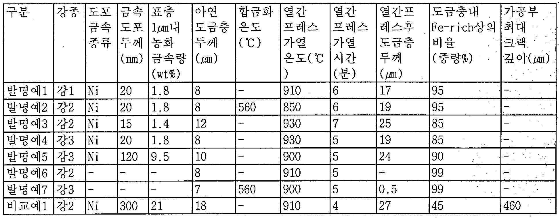
- the plated layer was analyzed by XRD and G0EDS on the surface, and the oxide formed on the surface and the alloy phase in the plated layer were analyzed. -rich phase) The ratio was measured.
- the thickness of the coating layer was measured by a length of up to more than 30% by weight content in the perpendicular ice "hyangeu plating layer from the surface of the plating layer after the hot press Zn point: the processing gokreul a radius 12 ⁇ to examine the part cracks The depth of the cracks generated in the direction of the steel sheet in the section of the cut section was measured, and the respective test tanks and the measurement results are shown in Table 10 below.
- Inventive Examples 1 to 7 are hot so that the galvanized layer thickness does not exceed 15 ;
- the ratio of the Fe-rich phase in the plating layer to 70 weight sub-phases with respect to the entire plating layer after the press process, it was possible to suppress the cracks in the processed portion.
- Inventive Examples 1 to 5 controlled the annealing oxide thinly between the base steel sheet and the plating layer through the metal surface diffusion layer so that Fe of the base iron was diffused into the galvanized layer and alloyed.
- the Zn of the plated layer even after hot press heating. It can be confirmed that the plating layer was kept thick without loss of heat resistance and excellent heat resistance and corrosion resistance were also ensured. have.
- Comparative Example 1 the amount of Ni coating was too high, and the amount of concentrated metal in the surface layer 1 was excessively 3 ⁇ 4. Accordingly, the annealing oxide was excessively thin, and the alloying proceeded too fast, resulting in a thickness of 18.
- the ratio of Fe-rich phase in the plated layer was increased to 45 3 ⁇ 4, which was a maximum of 460. This is because the Zn-rich phase is too much than the 3 ⁇ 4 3 ⁇ 4 Fe-rich phase in the plated layer, Zn was present in the liquid phase, which can be analyzed as having an effect on the generation of cracks in the steel sheet.
- Fe-rich phase having a Fe content of 60% by weight or more exceeded 70 weight 3 ⁇ 4> of the entire plating layer In FIG. 5, a deep stack was formed along the steel sheet in the processing part, whereas the Fe-rich phase was 70 In FIG. 6 exceeding the weight%, hardly any cracks appear in the processing part, and thus it may be confirmed that workability is very excellent.
- G0EDS analysis was used to measure the thickness of the thin metal coating layer, the amount of metal enriched from the surface to 1 / ⁇ depth, and ⁇ plating, and SEM, ⁇ observation, wet analysis, and electrospectral chemistry of the cross section of the specimen to improve the accuracy of the data. Verification was made by analysis (ESCA). Then, a hot pressing process was applied to the hot-dip galvanized steel sheet; The temperature of the hot press furnace was carried out at 750 ⁇ 950 ° C and the atmosphere of the furnace was in the air. After the hot pressing process, the plated layer was analyzed for oxides formed on the surface and alloy phases in the plated layer by XRD and GOEDS analysis.
- the thickness of the plated layer and the state of the plated layer were measured by analyzing only 1 ⁇ of the specimen.
- the thickness of the coating layer was measured by a length of up to more than 30% by weight content in the Zn plating layer in the vertical direction from the surface of the plating layer after the hot press point, "is shown in each of the experimental conditions and the measurement results of the following table 12 .
- Inventive Example 4 Steel 3 Ni 20 1.8 8-930 7 19 0.08: Hours:.
- Inventive Example 5 Steel 3 Fe-Ni 200 16 10-900 5 24 ⁇ .34 ⁇ :
- Inventive Example 6 Steel 2 Co 50 4.5 12-900 6 25 0.12 ' . ⁇ 7 to honor the river 3 Ni 10 0.8 7 - 750 7 14 0.06:; Comparative Example 1 Steel 2.---12-900 7--Comparative Example 2 Steel 3---7 560 910 5-Comparative Example 3 Steel 3---7 560 770 5 2-Comparative Example 4 Steel 3--- 10 560 910 5-Comparative Example 5 Steel 3--10-910 6-
- Inventive Examples 1 to 7 concentrate the metal in the surface layer through metal coating, and it can be confirmed that the plating layer is stably maintained even after hot press heating.
- the amount of thickened metal in the plating layer after the hot press is present in layers, it can be analyzed that the loss of Zn of the galvanized layer through the ternary phase formation was effectively prevented.
- Comparative Examples 1 to 5 did not concentrate metals in the surface layer by omitting metal coating, and thus it was confirmed that the plating layer was lost after hot press heating.
- the present inventors conducted the following experiment to confirm the relationship between the A1 2 0 3 oxide film formed on the plating layer and the thickness or state of the plating layer, and further confirm the effect of the oxide film on the coating property.
- the continuity and thickness of the A1 2 0 3 oxide film were measured by measuring the distribution of elements in the depth direction ⁇ using G0EDS.
- the surface of the specimen was processed by FIB and observed by transmission electron microscope (TEM).
- TEM transmission electron microscope
- A1 2 0 3 Upper layer of oxide film The thickness of the oxide was measured using G0EDS.
- the coating was also evaluated by the £ 3 ⁇ 4 ⁇ treatment on the surface and the results are shown in Table 13.
- Examples 1 to 7 are ⁇ 1 2 0 3 was formed by 40 ⁇ 100nm oxide film continuously, did not exceed 5 degrees upper oxide thickness was more than 50% by weight ZnO content also of those. Therefore, it can be seen that the Zn of the zinc plated layer is suppressed from being deteriorated by the thickness and structure of the oxide layer, thereby contributing to the stable maintenance of the zinc-plated layer as shown in Table 12 above.
- the present inventors conducted experiments of the phosphate treatment and the non-phosphate treatment of the invention examples 1 and 2, respectively, and after the electrodeposition coating treatment, the diagonal of the specimen was measured. After cutting the electrodeposition coating layer with an X, the average and the maximum value of the peeling width of the plating worm around the sheath were measured after the CCT 10 cycle test. In Comparative Examples 1 and 2, since the paintability was poor, the experiment was performed after the phosphate treatment and the coating treatment, and the results are shown in Table 14.
- the amount of phosphate deposition shows that Inventive Examples 1 and 2 are significantly higher than Comparative Examples 1 and 2, which shows that the phosphate treatment adhesion is also improved as the A1 2 0 3 oxide film is continuously formed.
- the invention examples 1 and 2 were 3 ⁇ 4 less than those of the comparative examples 1 and 2, the coating film adhesion degree as the A1 2 0 3 oxide film was continuously formed. You can see that it is very improved.
- FIG. 8 is a cross-sectional view of a hot-dip galvanized steel sheet prepared according to Inventive Example 3; in the distribution photographs of A1 and Ni, Ni is formed directly below the surface of the base steel sheet, and A1 is directly above the ' :! It can be seen that there is a concentrated layer. That is, the portion where Ni is concentrated is a metal surface diffusion layer, and the A1 enrichment layer is present thereon.
- the extruded Ni diffuses into the plating layer during hot press heating to form a ternary phase with Zn-Fe, thereby suppressing the diffusion of Zn in the zinc plating layer into the base steel sheet, and A1 is diffused over the plating layer to produce an A1 2 0 3 oxide film.
- Will form. 9 is a magnified photograph of Al and Ni distribution, where A1 is concentrated just above the Ni based on the dotted line, and the portion indicated in red in the drawing has a large amount of each enrichment. It contains more than and corresponds to the part which contains 30 weight% or more of A1 in A1 photograph. That is, the red portion on the A1 photograph and the ⁇ photograph; In the red part, it can be confirmed that the area where both parts overlap is 10% or less.
Abstract
Description


Claims
Priority Applications (7)
| Application Number | Priority Date | Filing Date | Title |
|---|---|---|---|
| EP10841224.8A EP2520686B1 (en) | 2009-12-29 | 2010-12-28 | Hot-pressed parts with zinc-plating and a production method for the same |
| CN201080064948.3A CN102791901B (zh) | 2009-12-29 | 2010-12-28 | 用于热压的具有显著表面特性的镀锌钢板,使用该钢板得到的热压模塑部件,以及其制备方法 |
| US13/518,904 US9068255B2 (en) | 2009-12-29 | 2010-12-28 | Zinc-plated steel sheet for hot pressing having outstanding surface characteristics, hot-pressed moulded parts obtained using the same, and a production method for the same |
| ES10841224T ES2876258T3 (es) | 2009-12-29 | 2010-12-28 | Partes prensadas en caliente con chapadas con zinc y procedimiento de producción de las mismas |
| JP2012547008A JP5676642B2 (ja) | 2009-12-29 | 2010-12-28 | 表面特性に優れた熱間プレス用亜鉛めっき鋼板並びにこれを利用した熱間プレス成形部品及びその製造方法 |
| US14/703,065 US9945020B2 (en) | 2009-12-29 | 2015-05-04 | Zinc-plated steel sheet for hot pressing having outstanding surface characteristics, hot-pressed moulded parts obtained using the same, and a production method for the same |
| US15/914,389 US11952652B2 (en) | 2009-12-29 | 2018-03-07 | Zinc-plated steel sheet for hot pressing having outstanding surface characteristics, hot-pressed moulded parts obtained using the same, and a production method for the same |
Applications Claiming Priority (10)
| Application Number | Priority Date | Filing Date | Title |
|---|---|---|---|
| KR1020090132777A KR101253818B1 (ko) | 2009-12-29 | 2009-12-29 | 표면특성이 우수한 열간 프레스용 용융아연도금강판, 이를 이용한 열간 프레스 부재 및 이들의 제조방법 |
| KR10-2009-0132777 | 2009-12-29 | ||
| KR1020100136211A KR101115754B1 (ko) | 2010-12-28 | 2010-12-28 | 강도 및 표면특성이 우수한 열간 프레스용 아연도금강판 및 이를 이용한 열간프레스 성형부품 |
| KR10-2010-0136212 | 2010-12-28 | ||
| KR1020100136214A KR101115848B1 (ko) | 2010-12-28 | 2010-12-28 | 표면특성이 우수한 열간 프레스용 아연도금강판 및 이를 이용한 열간 프레스 성형부품 |
| KR1020100136212A KR101197891B1 (ko) | 2010-12-28 | 2010-12-28 | 내열성 및 내식성이 우수한 열간프레스 성형부품 |
| KR1020100136213A KR101171620B1 (ko) | 2010-12-28 | 2010-12-28 | 가공성이 우수한 열간프레스 성형부품 |
| KR10-2010-0136214 | 2010-12-28 | ||
| KR10-2010-0136213 | 2010-12-28 | ||
| KR10-2010-0136211 | 2010-12-28 |
Related Child Applications (2)
| Application Number | Title | Priority Date | Filing Date |
|---|---|---|---|
| US13/518,904 A-371-Of-International US9068255B2 (en) | 2009-12-29 | 2010-12-28 | Zinc-plated steel sheet for hot pressing having outstanding surface characteristics, hot-pressed moulded parts obtained using the same, and a production method for the same |
| US14/703,065 Division US9945020B2 (en) | 2009-12-29 | 2015-05-04 | Zinc-plated steel sheet for hot pressing having outstanding surface characteristics, hot-pressed moulded parts obtained using the same, and a production method for the same |
Publications (4)
| Publication Number | Publication Date |
|---|---|
| WO2011081392A2 true WO2011081392A2 (ko) | 2011-07-07 |
| WO2011081392A9 WO2011081392A9 (ko) | 2011-10-13 |
| WO2011081392A3 WO2011081392A3 (ko) | 2011-12-01 |
| WO2011081392A4 WO2011081392A4 (ko) | 2012-01-19 |
Family
ID=44226999
Family Applications (1)
| Application Number | Title | Priority Date | Filing Date |
|---|---|---|---|
| PCT/KR2010/009392 WO2011081392A2 (ko) | 2009-12-29 | 2010-12-28 | 표면특성이 우수한 열간 프레스용 아연도금강판, 이를 이용한 열간 프레스 성형부품 및 그 제조방법 |
Country Status (6)
| Country | Link |
|---|---|
| US (3) | US9068255B2 (ko) |
| EP (1) | EP2520686B1 (ko) |
| JP (2) | JP5676642B2 (ko) |
| CN (2) | CN102791901B (ko) |
| ES (1) | ES2876258T3 (ko) |
| WO (1) | WO2011081392A2 (ko) |
Cited By (2)
| Publication number | Priority date | Publication date | Assignee | Title |
|---|---|---|---|---|
| JP2014520961A (ja) * | 2011-07-15 | 2014-08-25 | ポスコ | 熱間プレス成形用鋼板、それを用いた成形部材及びそれらの製造方法 |
| US20150292075A1 (en) * | 2012-05-03 | 2015-10-15 | Edward William Schleichert | Automotive components formed of sheet metal coated with a non-metallic coating |
Families Citing this family (33)
| Publication number | Priority date | Publication date | Assignee | Title |
|---|---|---|---|---|
| JP5860959B2 (ja) | 2011-06-28 | 2016-02-16 | ポスコ | めっき層の安定性に優れた熱間プレス成形用めっき鋼板 |
| CN103160764A (zh) * | 2013-03-25 | 2013-06-19 | 冷水江钢铁有限责任公司 | 一种复合带钢的单面连续热镀锌方法 |
| RU2018134251A (ru) | 2013-05-17 | 2019-03-20 | Ак Стил Пропертиз, Инк. | Сталь с цинковым покрытием для упрочнения под прессом, применения и способ изготовления |
| DE102013017798A1 (de) * | 2013-10-25 | 2015-04-30 | GM Global Technology Operations LLC (n. d. Ges. d. Staates Delaware) | Verbundstahlblech |
| JP6211908B2 (ja) * | 2013-12-02 | 2017-10-11 | トヨタ自動車株式会社 | ホットスタンプ成形品の製造方法 |
| JP2016089274A (ja) * | 2014-11-04 | 2016-05-23 | 株式会社神戸製鋼所 | ホットスタンプ用めっき鋼板 |
| DE102015119417B4 (de) * | 2014-11-26 | 2017-10-19 | GM Global Technology Operations LLC (n. d. Ges. d. Staates Delaware) | Verfahren zum presshärten einer galvanisierten stahllegierung |
| DE102015202642A1 (de) * | 2015-02-13 | 2016-08-18 | Muhr Und Bender Kg | Verfahren zum Herstellen eines Erzeugnisses aus gewalztem Bandmaterial |
| WO2017017485A1 (en) | 2015-07-30 | 2017-02-02 | Arcelormittal | A method for the manufacture of a phosphatable part starting from a steel sheet coated with a metallic coating based on aluminium |
| WO2017017484A1 (en) | 2015-07-30 | 2017-02-02 | Arcelormittal | Method for the manufacture of a hardened part which does not have lme issues |
| WO2017017483A1 (en) | 2015-07-30 | 2017-02-02 | Arcelormittal | Steel sheet coated with a metallic coating based on aluminum |
| JP2017066508A (ja) * | 2015-10-02 | 2017-04-06 | 株式会社神戸製鋼所 | 熱間プレス用亜鉛めっき鋼板および熱間プレス成形品の製造方法 |
| CN105385927A (zh) * | 2015-10-15 | 2016-03-09 | 无锡贺邦金属制品有限公司 | 一种汽车用骨架油封 |
| CN105272190A (zh) * | 2015-10-15 | 2016-01-27 | 无锡贺邦金属制品有限公司 | 一种汽车用消声器吊架 |
| CN105276288A (zh) * | 2015-10-15 | 2016-01-27 | 无锡贺邦金属制品有限公司 | 一种汽车用油管卡箍 |
| CN105226420A (zh) * | 2015-10-15 | 2016-01-06 | 无锡贺邦金属制品有限公司 | 一种汽车用接线端子 |
| KR20170075046A (ko) * | 2015-12-22 | 2017-07-03 | 주식회사 포스코 | 내식성이 우수한 열간 프레스 성형품 및 그 제조방법 |
| KR102075182B1 (ko) * | 2015-12-24 | 2020-02-10 | 주식회사 포스코 | 도금성이 우수한 고강도 용융 아연계 도금 강재 및 그 제조방법 |
| US10385415B2 (en) | 2016-04-28 | 2019-08-20 | GM Global Technology Operations LLC | Zinc-coated hot formed high strength steel part with through-thickness gradient microstructure |
| US10619223B2 (en) | 2016-04-28 | 2020-04-14 | GM Global Technology Operations LLC | Zinc-coated hot formed steel component with tailored property |
| CN106739270A (zh) * | 2016-11-24 | 2017-05-31 | 东台银信钢结构工程有限公司 | 一种高密度钢板及其生产工艺 |
| KR101988724B1 (ko) | 2017-06-01 | 2019-06-12 | 주식회사 포스코 | 도금 밀착성이 우수한 열간 프레스 성형 부재용 강판 및 그 제조방법 |
| CN107217199A (zh) * | 2017-06-01 | 2017-09-29 | 安徽诚远医疗科技有限公司 | 一种护士站专用电解钢板 |
| DE102017211076B4 (de) * | 2017-06-29 | 2019-03-14 | Thyssenkrupp Ag | Verfahren zum Herstellen eines mit einem Überzug versehenen Stahlbauteils und Stahlbauteil |
| US11566310B2 (en) | 2017-11-17 | 2023-01-31 | Arcelormittal | Method for the manufacturing of liquid metal embrittlement resistant zinc coated steel sheet |
| JP7006257B2 (ja) * | 2017-12-27 | 2022-01-24 | 日本製鉄株式会社 | ホットスタンプ成形体及びホットスタンプ成形体の製造方法 |
| WO2019171157A1 (en) * | 2018-03-09 | 2019-09-12 | Arcelormittal | A manufacturing process of press hardened parts with high productivity |
| WO2019180492A1 (en) * | 2018-03-23 | 2019-09-26 | Arcelormittal | Forged part of bainitic steel and a method of manufacturing thereof |
| WO2019222950A1 (en) | 2018-05-24 | 2019-11-28 | GM Global Technology Operations LLC | A method for improving both strength and ductility of a press-hardening steel |
| CN112534078A (zh) | 2018-06-19 | 2021-03-19 | 通用汽车环球科技运作有限责任公司 | 具有增强的机械性质的低密度压制硬化钢 |
| US11530469B2 (en) | 2019-07-02 | 2022-12-20 | GM Global Technology Operations LLC | Press hardened steel with surface layered homogenous oxide after hot forming |
| KR20220154177A (ko) * | 2020-03-12 | 2022-11-21 | 닛폰세이테츠 가부시키가이샤 | 핫 스탬프용 도금 강판 |
| JP7331817B2 (ja) * | 2020-10-07 | 2023-08-23 | 株式会社村田製作所 | フェライト焼結体および巻線型コイル部品 |
Citations (1)
| Publication number | Priority date | Publication date | Assignee | Title |
|---|---|---|---|---|
| US6296805B1 (en) | 1998-07-09 | 2001-10-02 | Sollac | Coated hot- and cold-rolled steel sheet comprising a very high resistance after thermal treatment |
Family Cites Families (42)
| Publication number | Priority date | Publication date | Assignee | Title |
|---|---|---|---|---|
| JPS5776176A (en) * | 1980-10-28 | 1982-05-13 | Nippon Steel Corp | Manufacture of high preformance hot-galvanized steel plate |
| JPS58117866A (ja) * | 1981-12-29 | 1983-07-13 | Nippon Steel Corp | 両面異種被覆鋼板の製造法 |
| JPS6060376U (ja) | 1983-10-03 | 1985-04-26 | トヨタ自動車株式会社 | スペアタイヤ格納装置 |
| JPS6088187U (ja) | 1983-11-22 | 1985-06-17 | 豊田工機株式会社 | 圧力流体供給ホース |
| JPH0635648B2 (ja) * | 1989-03-10 | 1994-05-11 | 新日本製鐵株式会社 | 低温加熱、還元省略型の亜鉛又は亜鉛系合金の溶融めっき方法 |
| JPH0660376B2 (ja) * | 1990-07-03 | 1994-08-10 | 新日本製鐵株式会社 | 加工性に優れた溶融合金化亜鉛めっき鋼板及びその製造方法 |
| JP2517169B2 (ja) * | 1990-10-09 | 1996-07-24 | 新日本製鐵株式会社 | 溶融亜鉛めっき鋼板の製造方法 |
| JPH04314848A (ja) * | 1991-04-15 | 1992-11-06 | Nippon Steel Corp | 加工性に優れた高張力合金化溶融亜鉛めっき鋼板の製造方法 |
| US5447802A (en) | 1992-03-30 | 1995-09-05 | Kawasaki Steel Corporation | Surface treated steel strip with minimal plating defects and method for making |
| US5453802A (en) | 1992-06-10 | 1995-09-26 | Sony Electronics Inc. | Method and apparatus for photographically recording digital audio and a medium having photographically recorded digital sountracks |
| JPH0688187A (ja) | 1992-09-03 | 1994-03-29 | Nkk Corp | 合金化溶融亜鉛めっき鋼板の製造方法 |
| JP2707928B2 (ja) * | 1992-10-20 | 1998-02-04 | 住友金属工業株式会社 | 珪素含有鋼板の溶融亜鉛めっき方法 |
| DE4432060A1 (de) | 1994-09-09 | 1996-03-14 | Volker Ludwig | Titer-Ring |
| DE69728389T2 (de) * | 1997-01-13 | 2005-02-24 | Jfe Steel Corp. | Heissgetauchtes galvanisiertes stahlblech mit verminderten defekten, entstanden durch fehlbeschichtung, mit hervorragender kontaktbeschichtungshaftung und verfahren zu dessen herstellung |
| JP3397150B2 (ja) * | 1998-11-25 | 2003-04-14 | 住友金属工業株式会社 | 溶融亜鉛系めっき鋼板 |
| JP4886118B2 (ja) | 2001-04-25 | 2012-02-29 | 株式会社神戸製鋼所 | 溶融亜鉛めっき鋼板 |
| AU2002309283B2 (en) * | 2001-06-15 | 2005-04-14 | Nippon Steel Corporation | High-strength Alloyed Aluminum-system Plated Steel Sheet and High-strength Automotive Part Excellent in Heat Resistance and After-painting Corrosion Resistance |
| JP3582504B2 (ja) * | 2001-08-31 | 2004-10-27 | 住友金属工業株式会社 | 熱間プレス用めっき鋼板 |
| CN100434564C (zh) * | 2001-10-23 | 2008-11-19 | 住友金属工业株式会社 | 热压成型方法,其电镀钢材及其制备方法 |
| CN1985016B (zh) * | 2003-01-15 | 2011-09-14 | 新日本制铁株式会社 | 高强度热浸镀锌钢板及其制备方法 |
| JP2004270029A (ja) | 2003-02-18 | 2004-09-30 | Nippon Steel Corp | 耐亜鉛揮発性に優れた亜鉛系めっき鋼板 |
| BRPI0408983B1 (pt) * | 2003-03-31 | 2014-08-05 | Nippon Steel & Sumitomo Metal Corp | Folha de aço revestida com liga de zinco fundido e processo de produção da mesma |
| CA2521710C (en) * | 2003-04-10 | 2009-09-29 | Nippon Steel Corporation | High strength molten zinc plated steel sheet and process of production of same |
| EP1630244B2 (en) * | 2003-04-23 | 2016-08-17 | Nippon Steel & Sumitomo Metal Corporation | Hot press formed product and method for production thereof |
| JP4085876B2 (ja) * | 2003-04-23 | 2008-05-14 | 住友金属工業株式会社 | 熱間プレス成形品およびその製造方法 |
| JP4506128B2 (ja) | 2003-08-29 | 2010-07-21 | 住友金属工業株式会社 | 熱間プレス成形品およびその製造方法 |
| JP2005113233A (ja) * | 2003-10-09 | 2005-04-28 | Nippon Steel Corp | 熱間プレス用Zn系めっき鋼材 |
| JP4671634B2 (ja) | 2004-07-09 | 2011-04-20 | 新日本製鐵株式会社 | 耐食性に優れた高強度焼き入れ成形体およびその製造方法 |
| JP4631379B2 (ja) | 2004-09-29 | 2011-02-16 | Jfeスチール株式会社 | 溶融亜鉛めっき鋼板及びその製造方法 |
| JP4449795B2 (ja) * | 2005-03-22 | 2010-04-14 | 住友金属工業株式会社 | 熱間プレス用熱延鋼板およびその製造方法ならびに熱間プレス成形部材の製造方法 |
| JP4551268B2 (ja) * | 2005-04-20 | 2010-09-22 | 新日本製鐵株式会社 | 合金化溶融亜鉛メッキ鋼板の製造方法 |
| JP4695459B2 (ja) | 2005-08-24 | 2011-06-08 | 新日本製鐵株式会社 | 塗装後耐食性に優れた亜鉛系めっきが施された熱間プレス鋼材 |
| KR101011897B1 (ko) * | 2005-10-14 | 2011-02-01 | 신닛뽄세이테쯔 카부시키카이샤 | Si를 함유하는 강판의 연속 어닐링 용융 도금 방법 및연속 어닐링 용융 도금 장치 |
| WO2007064172A1 (en) | 2005-12-01 | 2007-06-07 | Posco | Steel sheet for hot press forming having excellent heat treatment and impact property, hot press parts made of it and the method for manufacturing thereof |
| CN101316942A (zh) * | 2005-12-01 | 2008-12-03 | Posco公司 | 用于热压成形的具有优良的热处理和冲击性质的钢板,由该钢板制造的热压部件及其制造方法 |
| JP4975406B2 (ja) | 2006-10-02 | 2012-07-11 | 住友金属工業株式会社 | 高張力合金化溶融亜鉛めっき鋼板およびその製造方法 |
| JP4411326B2 (ja) | 2007-01-29 | 2010-02-10 | 株式会社神戸製鋼所 | リン酸塩処理性に優れた高強度合金化溶融亜鉛めっき鋼板 |
| EP2009129A1 (en) | 2007-06-29 | 2008-12-31 | ArcelorMittal France | Process for manufacturing a galvannealed steel sheet by DFF regulation |
| DE102009018577B3 (de) * | 2009-04-23 | 2010-07-29 | Thyssenkrupp Steel Europe Ag | Verfahren zum Schmelztauchbeschichten eines 2-35 Gew.-% Mn enthaltenden Stahlflachprodukts und Stahlflachprodukt |
| JP4849186B2 (ja) | 2009-10-28 | 2012-01-11 | Jfeスチール株式会社 | 熱間プレス部材およびその製造方法 |
| JP6088187B2 (ja) | 2012-09-26 | 2017-03-01 | 日東電工株式会社 | 光学表示パネルの連続製造方法及び光学表示パネルの連続製造システム |
| JP6060376B2 (ja) | 2012-09-27 | 2017-01-18 | パナソニックIpマネジメント株式会社 | 自己始動形永久磁石同期電動機およびそれを搭載した送風装置 |
-
2010
- 2010-12-28 CN CN201080064948.3A patent/CN102791901B/zh active Active
- 2010-12-28 JP JP2012547008A patent/JP5676642B2/ja active Active
- 2010-12-28 EP EP10841224.8A patent/EP2520686B1/en active Active
- 2010-12-28 ES ES10841224T patent/ES2876258T3/es active Active
- 2010-12-28 CN CN201410569450.2A patent/CN104388870B/zh active Active
- 2010-12-28 US US13/518,904 patent/US9068255B2/en active Active
- 2010-12-28 WO PCT/KR2010/009392 patent/WO2011081392A2/ko active Application Filing
-
2014
- 2014-05-23 JP JP2014106911A patent/JP5879390B2/ja active Active
-
2015
- 2015-05-04 US US14/703,065 patent/US9945020B2/en active Active
-
2018
- 2018-03-07 US US15/914,389 patent/US11952652B2/en active Active
Patent Citations (1)
| Publication number | Priority date | Publication date | Assignee | Title |
|---|---|---|---|---|
| US6296805B1 (en) | 1998-07-09 | 2001-10-02 | Sollac | Coated hot- and cold-rolled steel sheet comprising a very high resistance after thermal treatment |
Cited By (3)
| Publication number | Priority date | Publication date | Assignee | Title |
|---|---|---|---|---|
| JP2014520961A (ja) * | 2011-07-15 | 2014-08-25 | ポスコ | 熱間プレス成形用鋼板、それを用いた成形部材及びそれらの製造方法 |
| US20150292075A1 (en) * | 2012-05-03 | 2015-10-15 | Edward William Schleichert | Automotive components formed of sheet metal coated with a non-metallic coating |
| US9988706B2 (en) * | 2012-05-03 | 2018-06-05 | Magna International Inc. | Automotive components formed of sheet metal coated with a non-metallic coating |
Also Published As
| Publication number | Publication date |
|---|---|
| EP2520686A2 (en) | 2012-11-07 |
| EP2520686B1 (en) | 2021-04-07 |
| CN104388870A (zh) | 2015-03-04 |
| CN102791901B (zh) | 2015-05-06 |
| US20150307977A1 (en) | 2015-10-29 |
| JP5676642B2 (ja) | 2015-02-25 |
| CN102791901A (zh) | 2012-11-21 |
| JP5879390B2 (ja) | 2016-03-08 |
| US20180195159A1 (en) | 2018-07-12 |
| US11952652B2 (en) | 2024-04-09 |
| WO2011081392A3 (ko) | 2011-12-01 |
| WO2011081392A9 (ko) | 2011-10-13 |
| EP2520686A4 (en) | 2017-08-30 |
| JP2013515863A (ja) | 2013-05-09 |
| CN104388870B (zh) | 2017-04-12 |
| ES2876258T3 (es) | 2021-11-12 |
| JP2014221943A (ja) | 2014-11-27 |
| WO2011081392A4 (ko) | 2012-01-19 |
| US20120267012A1 (en) | 2012-10-25 |
| US9945020B2 (en) | 2018-04-17 |
| US9068255B2 (en) | 2015-06-30 |
Similar Documents
| Publication | Publication Date | Title |
|---|---|---|
| WO2011081392A2 (ko) | 표면특성이 우수한 열간 프레스용 아연도금강판, 이를 이용한 열간 프레스 성형부품 및 그 제조방법 | |
| JP5860959B2 (ja) | めっき層の安定性に優れた熱間プレス成形用めっき鋼板 | |
| US8592049B2 (en) | High strength hot dip galvanized steel sheet and high strength galvannealed steel sheet excellent in shapeability and plateability | |
| CN111936650B (zh) | 高强度镀锌钢板、高强度部件和它们的制造方法 | |
| KR101624810B1 (ko) | 도금 습윤성 및 도금 밀착성이 우수한 용융 아연 도금층을 구비한 강판과 그 제조 방법 | |
| KR20140128458A (ko) | 고강도 용융 아연 도금 강판 및 그 제조 방법 | |
| JP4837464B2 (ja) | めっき密着性に優れた高強度溶融亜鉛めっき鋼板及びその製造方法 | |
| CN111936648B (zh) | 高强度镀锌钢板、高强度部件及其制造方法 | |
| KR101115816B1 (ko) | 표면특성이 우수한 열간 프레스용 고망간 아연도금강판 및 이를 이용한 열간 프레스 성형부품 | |
| KR101428151B1 (ko) | 고망간 열연 아연도금강판 및 그 제조방법 | |
| KR101115754B1 (ko) | 강도 및 표면특성이 우수한 열간 프레스용 아연도금강판 및 이를 이용한 열간프레스 성형부품 | |
| CN111936649B (zh) | 高强度镀锌钢板、高强度部件和它们的制造方法 | |
| KR101289219B1 (ko) | 도금층의 안정성이 우수한 열간 프레스 성형용 도금강판 | |
| JP4452126B2 (ja) | 合金化溶融亜鉛めっき用鋼板 | |
| JP4846550B2 (ja) | 合金化溶融亜鉛めっき用鋼板及び合金化溶融亜鉛めっき鋼板 | |
| KR101197891B1 (ko) | 내열성 및 내식성이 우수한 열간프레스 성형부품 | |
| KR101115848B1 (ko) | 표면특성이 우수한 열간 프레스용 아연도금강판 및 이를 이용한 열간 프레스 성형부품 | |
| KR101359161B1 (ko) | 내식성이 우수한 열간 프레스 성형용 도금강판 | |
| KR101171620B1 (ko) | 가공성이 우수한 열간프레스 성형부품 | |
| CN114746571A (zh) | 电阻点焊部的疲劳强度优异的镀锌钢板及其制造方法 | |
| KR20190078318A (ko) | 도금성이 우수한 초고강도 고망간 용융아연도금강판 및 그 제조방법 |
Legal Events
| Date | Code | Title | Description |
|---|---|---|---|
| WWE | Wipo information: entry into national phase |
Ref document number: 201080064948.3 Country of ref document: CN |
|
| 121 | Ep: the epo has been informed by wipo that ep was designated in this application |
Ref document number: 10841224 Country of ref document: EP Kind code of ref document: A1 |
|
| WWE | Wipo information: entry into national phase |
Ref document number: 13518904 Country of ref document: US |
|
| WWE | Wipo information: entry into national phase |
Ref document number: 2012547008 Country of ref document: JP |
|
| NENP | Non-entry into the national phase |
Ref country code: DE |
|
| WWE | Wipo information: entry into national phase |
Ref document number: 2010841224 Country of ref document: EP |