WO2011062065A1 - 双極型二次電池用集電体 - Google Patents
双極型二次電池用集電体 Download PDFInfo
- Publication number
- WO2011062065A1 WO2011062065A1 PCT/JP2010/069610 JP2010069610W WO2011062065A1 WO 2011062065 A1 WO2011062065 A1 WO 2011062065A1 JP 2010069610 W JP2010069610 W JP 2010069610W WO 2011062065 A1 WO2011062065 A1 WO 2011062065A1
- Authority
- WO
- WIPO (PCT)
- Prior art keywords
- layer
- current collector
- active material
- electrode active
- thickness
- Prior art date
Links
Images


Classifications
-
- H—ELECTRICITY
- H01—ELECTRIC ELEMENTS
- H01M—PROCESSES OR MEANS, e.g. BATTERIES, FOR THE DIRECT CONVERSION OF CHEMICAL ENERGY INTO ELECTRICAL ENERGY
- H01M4/00—Electrodes
- H01M4/02—Electrodes composed of, or comprising, active material
- H01M4/36—Selection of substances as active materials, active masses, active liquids
- H01M4/60—Selection of substances as active materials, active masses, active liquids of organic compounds
-
- H—ELECTRICITY
- H01—ELECTRIC ELEMENTS
- H01M—PROCESSES OR MEANS, e.g. BATTERIES, FOR THE DIRECT CONVERSION OF CHEMICAL ENERGY INTO ELECTRICAL ENERGY
- H01M10/00—Secondary cells; Manufacture thereof
- H01M10/05—Accumulators with non-aqueous electrolyte
- H01M10/052—Li-accumulators
-
- H—ELECTRICITY
- H01—ELECTRIC ELEMENTS
- H01M—PROCESSES OR MEANS, e.g. BATTERIES, FOR THE DIRECT CONVERSION OF CHEMICAL ENERGY INTO ELECTRICAL ENERGY
- H01M10/00—Secondary cells; Manufacture thereof
- H01M10/05—Accumulators with non-aqueous electrolyte
- H01M10/058—Construction or manufacture
- H01M10/0585—Construction or manufacture of accumulators having only flat construction elements, i.e. flat positive electrodes, flat negative electrodes and flat separators
-
- H—ELECTRICITY
- H01—ELECTRIC ELEMENTS
- H01M—PROCESSES OR MEANS, e.g. BATTERIES, FOR THE DIRECT CONVERSION OF CHEMICAL ENERGY INTO ELECTRICAL ENERGY
- H01M10/00—Secondary cells; Manufacture thereof
- H01M10/42—Methods or arrangements for servicing or maintenance of secondary cells or secondary half-cells
- H01M10/4235—Safety or regulating additives or arrangements in electrodes, separators or electrolyte
-
- H—ELECTRICITY
- H01—ELECTRIC ELEMENTS
- H01M—PROCESSES OR MEANS, e.g. BATTERIES, FOR THE DIRECT CONVERSION OF CHEMICAL ENERGY INTO ELECTRICAL ENERGY
- H01M4/00—Electrodes
- H01M4/02—Electrodes composed of, or comprising, active material
- H01M4/64—Carriers or collectors
- H01M4/66—Selection of materials
- H01M4/665—Composites
- H01M4/667—Composites in the form of layers, e.g. coatings
-
- H—ELECTRICITY
- H01—ELECTRIC ELEMENTS
- H01M—PROCESSES OR MEANS, e.g. BATTERIES, FOR THE DIRECT CONVERSION OF CHEMICAL ENERGY INTO ELECTRICAL ENERGY
- H01M4/00—Electrodes
- H01M4/02—Electrodes composed of, or comprising, active material
- H01M4/64—Carriers or collectors
- H01M4/66—Selection of materials
- H01M4/668—Composites of electroconductive material and synthetic resins
-
- H—ELECTRICITY
- H01—ELECTRIC ELEMENTS
- H01M—PROCESSES OR MEANS, e.g. BATTERIES, FOR THE DIRECT CONVERSION OF CHEMICAL ENERGY INTO ELECTRICAL ENERGY
- H01M10/00—Secondary cells; Manufacture thereof
- H01M10/04—Construction or manufacture in general
- H01M10/0413—Large-sized flat cells or batteries for motive or stationary systems with plate-like electrodes
- H01M10/0418—Large-sized flat cells or batteries for motive or stationary systems with plate-like electrodes with bipolar electrodes
-
- Y—GENERAL TAGGING OF NEW TECHNOLOGICAL DEVELOPMENTS; GENERAL TAGGING OF CROSS-SECTIONAL TECHNOLOGIES SPANNING OVER SEVERAL SECTIONS OF THE IPC; TECHNICAL SUBJECTS COVERED BY FORMER USPC CROSS-REFERENCE ART COLLECTIONS [XRACs] AND DIGESTS
- Y02—TECHNOLOGIES OR APPLICATIONS FOR MITIGATION OR ADAPTATION AGAINST CLIMATE CHANGE
- Y02E—REDUCTION OF GREENHOUSE GAS [GHG] EMISSIONS, RELATED TO ENERGY GENERATION, TRANSMISSION OR DISTRIBUTION
- Y02E60/00—Enabling technologies; Technologies with a potential or indirect contribution to GHG emissions mitigation
- Y02E60/10—Energy storage using batteries
-
- Y—GENERAL TAGGING OF NEW TECHNOLOGICAL DEVELOPMENTS; GENERAL TAGGING OF CROSS-SECTIONAL TECHNOLOGIES SPANNING OVER SEVERAL SECTIONS OF THE IPC; TECHNICAL SUBJECTS COVERED BY FORMER USPC CROSS-REFERENCE ART COLLECTIONS [XRACs] AND DIGESTS
- Y02—TECHNOLOGIES OR APPLICATIONS FOR MITIGATION OR ADAPTATION AGAINST CLIMATE CHANGE
- Y02P—CLIMATE CHANGE MITIGATION TECHNOLOGIES IN THE PRODUCTION OR PROCESSING OF GOODS
- Y02P70/00—Climate change mitigation technologies in the production process for final industrial or consumer products
- Y02P70/50—Manufacturing or production processes characterised by the final manufactured product
Definitions
- the present invention relates to a current collector for a bipolar secondary battery.
- the present invention relates to an improvement for suppressing a temperature increase of a bipolar secondary battery.
- hybrid vehicles HEV
- electric vehicles EV
- fuel cell vehicles have been manufactured and sold from the viewpoints of environment and fuel efficiency, and new developments are continuing.
- a power supply device such as a lithium ion battery or a nickel metal hydride battery, an electric double layer capacitor, or the like is used.
- lithium ion secondary batteries are considered suitable for electric vehicles because of their high energy density and high durability against repeated charging and discharging, and various developments have been intensively advanced.
- connection portion causes a reduction in the output density and energy density of the battery.
- a bipolar secondary battery is a power generator in which a positive electrode active material layer is formed on one surface of a current collector and a plurality of bipolar electrodes having a negative electrode active material layer formed on the other surface are stacked via an electrolyte layer.
- a positive electrode active material layer, the electrolyte layer, and the negative electrode active material layer form one unit cell layer, and a plurality of the unit cell layers are stacked in series via the current collector.
- an object of the present invention is to provide a current collector for a bipolar secondary battery that can suppress an increase in battery temperature.
- the bipolar secondary battery current collector of the present invention is a conductive bipolar secondary battery current collector.
- the current collector is characterized in that it has an expanding portion that expands in the thickness direction of the current collector at a temperature equal to or higher than a predetermined temperature.
- the expansion portion expands in the thickness direction of the current collector.
- the electrical resistance in the thickness direction of the current collector increases, and the amount of current flowing in that direction is reduced.
- an increase in battery temperature can be suppressed.
- FIG. 1 is a cross-sectional view schematically showing a current collector for a bipolar secondary battery according to a preferred embodiment of the present invention. It is sectional drawing which represented typically the whole structure of the bipolar secondary battery concerning one Embodiment of this invention.
- FIG. 6 is a cross-sectional view schematically showing bipolar electrodes produced in Examples 1 to 17.
- FIG. 6 is a cross-sectional view schematically showing bipolar electrodes manufactured in Comparative Examples 1 to 5.
- One embodiment of the present invention is a current collector for a bipolar secondary battery having conductivity.
- the current collector is characterized in that it has an expanding portion that expands in the thickness direction of the current collector at a temperature equal to or higher than a predetermined temperature.
- the current collector has a function of mediating transfer of electrons from one surface on which the positive electrode active material layer is formed to the other surface on which the negative electrode active material layer is formed.
- a current collector according to a preferred embodiment of the present invention includes a conductive resin layer (hereinafter also simply referred to as “resin layer”) and a conductive adhesive layer (hereinafter also simply referred to as “adhesive layer”). . Further, if necessary, other layers such as an ion blocking layer may be included. However, the scope of the present invention is not limited only to such embodiments, and all the embodiments are not included in the scope of the present invention even if these layers are not included as long as the requirements defined in the claims are satisfied. Can be included.
- FIG. 1 is a cross-sectional view schematically showing a current collector for a bipolar secondary battery according to a preferred embodiment of the present invention.
- Each of the current collectors (a) to (i) of FIG. 1 is formed by laminating a resin layer 1 having one or more conductivity and an adhesive layer 3 having one or more conductivity.
- the current collectors (a) to (c) have a form in which only one or two or more resin layers 1 and one or two or more adhesive layers 3 are laminated.
- the current collectors (d) to (i) further include an ion blocking layer 5 in addition to the resin layer 1 and the adhesive layer 3, and have a structure in which these are laminated.
- the ion blocking layer 5 is located on the outermost layer of one surface and / or the other surface of the current collector, and in the forms (g) to (i), the resin The layer 1 and / or the adhesive layer 3 has a structure in which the ion blocking layer 5 is sandwiched.
- one surface of at least one adhesive layer 3 is in contact with one surface of at least one resin layer 1.
- the adhesive layer 3 has a lower melting point than the resin layer 1.
- the current collector of the present invention is not limited to such a form.
- the resin layer 1 is made of, for example, a resin obtained by adding ketjen black as a conductive filler to polyethylene.
- the adhesive layer 3 is made of, for example, an adhesive containing thermally expandable microcapsules in which hexane as an expanding material is encapsulated in a shell made of polyvinyl chloride and carbon particles as a conductive filler.
- the thermally expandable microcapsule corresponds to the inflatable portion in the present invention. That is, it can be said that the adhesive layer 3 is an embodiment including an expanding portion.
- the ion blocking layer 5 is made of, for example, copper foil.
- the thermally expandable microcapsule included in the adhesive layer 3 of the current collector when the temperature rises, the expansion material contained in the shell is vaporized and expands. Thereby, when the temperature of the current collector rises to a predetermined temperature or higher, the adhesive layer 3 expands in the thickness direction (stacking direction) of the current collector. As a result, the electrical resistance in the thickness direction of the current collector increases, and the amount of current flowing in that direction is reduced.
- the adhesive layer 3 melts and the current collector is divided. This also increases the electrical resistance in the thickness direction of the current collector and can reduce the amount of current flowing in that direction. And if temperature rises further after that, the resin layer 1 will also fuse
- the conductive resin layer 1 has a function as an electron transfer medium, and can contribute to reducing the weight of the current collector.
- the resin layer 1 may include a base material made of a polymer material, and if necessary, a conductive filler and other members.
- non-conductive polymer materials include, for example, polyethylene (PE; high density polyethylene (HDPE), low density polyethylene (LDPE)), polypropylene (PP), polyethylene terephthalate (PET), polybutylene terephthalate (PBT), poly Ether nitrile (PEN), polyimide (PI), polyamideimide (PAI), polyamide (PA), polytetrafluoroethylene (PTFE), styrene-butadiene rubber (SBR), polyacrylonitrile (PAN), polymethyl acrylate (PMA) , Polymethyl methacrylate (PMMA), polyvinyl chloride (PVC), polyvinylidene fluoride (PVdF), polystyrene (PS), silicone resin, cellulose, and epoxy resin.
- PE polyethylene
- HDPE high density polyethylene
- LDPE low density polyethylene
- PP polypropylene
- PET polyethylene terephthalate
- PBT polybutylene terephthalate
- PEN poly Et
- Such a non-conductive polymer material may have excellent potential resistance or solvent resistance.
- preferable conductive polymer materials include polyaniline, polypyrrole, polythiophene, polyacetylene, polyparaphenylene, polyphenylene vinylene, polyacrylonitrile, and polyoxadiazole. Since such a conductive polymer material has sufficient conductivity without adding a conductive filler, it is advantageous in terms of facilitating the manufacturing process or reducing the weight of the current collector.
- the current collector of this embodiment may include one or more resin layers 1, but at least one of the resin layers 1 preferably includes a thermoplastic polymer material that melts by heating.
- the resin layer 1 when at least one resin layer 1 contains a thermoplastic polymer material, when the temperature inside the battery rises, the resin layer 1 melts and an active material formed on the surface of the current collector by the melted resin The layer can be covered. This is preferable because an exothermic reaction between the active material layer and the electrolyte can be suppressed and an increase in battery temperature can be prevented.
- non-conductive polymer materials or conductive materials can be appropriately selected by those skilled in the art depending on the use temperature of the bipolar secondary battery. Further, one kind of polymer material may be used alone, or two or more kinds of polymer materials may be used in combination as a mixture. Further, when the current collector includes two or more resin layers 1, different polymer materials may be used for each resin layer 1.
- a conductive filler may be added to the conductive polymer material or the non-conductive polymer material as necessary.
- a conductive filler is inevitably necessary to impart conductivity to the resin.
- the conductive filler can be used without particular limitation as long as it is a substance having conductivity.
- metals, conductive carbon, etc. are mentioned as a material excellent in electroconductivity, electric potential resistance, or lithium ion barrier
- the metal is not particularly limited, but at least one metal selected from the group consisting of Ni, Ti, Al, Cu, Pt, Fe, Cr, Sn, Zn, In, Sb, and K, or these metals It is preferable to contain an alloy or metal oxide containing. These metals are resistant to the potential of the positive electrode or negative electrode formed on the current collector surface. Among these, an alloy containing at least one metal selected from the group consisting of Ni, Ti, Al, Cu, Pt, Fe, and Cr is more preferable.
- the alloy examples include stainless steel (SUS), Inconel (registered trademark), Hastelloy (registered trademark), and other Fe—Cr alloys, Ni—Cr alloys, and the like. By using these alloys, higher potential resistance can be obtained.
- the conductive carbon is not particularly limited, but at least selected from the group consisting of acetylene black, vulcan, black pearl, carbon nanofiber, ketjen black, carbon nanotube, carbon nanohorn, carbon nanoballoon, and fullerene. It is preferable that 1 type is included. These conductive carbons have a very wide potential window, are stable in a wide range with respect to both the positive electrode potential and the negative electrode potential, and have excellent conductivity. Further, since the density is lower than that of the conductive filler containing the above metal, the current collector can be reduced in weight.
- electroconductive fillers such as these metals and electroconductive carbon, can be used individually by 1 type or in combination of 2 or more types. Further, when the current collector includes two or more resin layers 1, different conductive fillers may be used for each resin layer 1.
- the size of the conductive filler is not particularly limited, and fillers of various sizes can be used depending on the size and thickness of the resin layer 1 or the shape of the conductive filler.
- the average particle diameter when the conductive filler is granular is preferably about 0.1 to 10 ⁇ m from the viewpoint of facilitating molding of the resin layer 1.
- “particle diameter” means the maximum distance L among the distances between any two points on the contour line of the conductive filler.
- the value of “average particle size” is the average value of the particle size of particles observed in several to several tens of fields using an observation means such as a scanning electron microscope (SEM) or a transmission electron microscope (TEM). The calculated value shall be adopted.
- SEM scanning electron microscope
- TEM transmission electron microscope
- the content of the conductive filler contained in the resin layer 1 is not particularly limited.
- the resin includes a conductive polymer material and sufficient conductivity can be secured, it is not always necessary to add a conductive filler.
- the resin is made of only a nonconductive polymer material, it is essential to add a conductive filler in order to impart conductivity.
- the content of the conductive filler is preferably 5 to 35% by mass, more preferably 5 to 25% by mass, and further preferably 5 to 5% by mass with respect to the total mass of the non-conductive polymer material. 15% by mass.
- the shape of the conductive filler is not particularly limited, and a known shape such as a granular shape, a fibrous shape, a plate shape, a lump shape, a cloth shape, and a mesh shape can be appropriately selected.
- a known shape such as a granular shape, a fibrous shape, a plate shape, a lump shape, a cloth shape, and a mesh shape.
- a granular conductive filler when it is desired to impart conductivity to a resin over a wide range, it is preferable to use a granular conductive filler.
- the thickness of the conductive resin layer 1 is preferably thin in order to increase the output density of the battery by reducing the weight.
- the thickness of one layer of the resin layer 1 having conductivity is preferably 0.1 to 200 ⁇ m, more preferably 5 to 150 ⁇ m, and further preferably 10 to 100 ⁇ m. preferable.
- the conductive adhesive layer 3 has a function of bonding the constituent members (each layer) included in the current collector or the current collector and the active material layer formed on the surface of the current collector. Furthermore, the adhesive layer 3 according to the present embodiment has a function of expanding in the stacking direction of the current collector at a temperature lower than the melting point of the adhesive layer itself.
- “expand” means that the thickness is 1.05 times or more the thickness of the adhesive layer in the thickness direction (lamination direction) at 25 ° C.
- the material constituting the adhesive layer 3 is not particularly limited as long as it has an adhesive function and a function of expanding in the thickness direction (lamination direction) due to an increase in temperature, and a conventionally known material can be appropriately employed.
- the adhesive layer 3 includes a thermally expandable microcapsule in which an expansion material is included in a shell including a thermoplastic polymer material in order to impart a function of expanding. In the thermally expandable microcapsule, when the temperature rises, the expansion material is vaporized to expand the shell. Thereby, the adhesive layer 3 can be expanded in the thickness direction (lamination direction).
- thermoplastic polymer material contained in the shell of the thermally expandable microcapsule is not particularly limited, but when the temperature of the bipolar secondary battery rises, other battery components (resin layer 1 and adhesive layer) 3 substrate) must be melted prior to (ie, at a lower temperature) the thermal decomposition.
- a thermoplastic polymer material constituting the shell of the thermally expandable microcapsule can be selected. Examples include polyethylene, polypropylene, polyvinyl alcohol, polyvinyl acetal, polyvinyl acetate, polyvinyl chloride, acrylic resin, and elastomers such as chloroprene rubber, nitrile rubber, styrene-butadiene rubber (SBR), butyl rubber, and silicone rubber. Of these thermoplastic polymer materials, it is preferable to include polyethylene or polypropylene.
- the expansion material included in the shell of the heat-expandable microcapsule is not particularly limited as long as it can vaporize as the temperature rises and expand the shell. You can choose.
- the adhesive layer 3 can be expanded in the thickness direction (lamination direction) as described above by evaporating the expansion material before the shell of the microcapsule melts and expanding the shell. For this reason, in this embodiment, it is necessary for the boiling point of an expansion material to be lower than the thermoplastic polymer material which comprises a shell.
- the type of expansion material can be selected in consideration of the type of material used for the shell (particularly its melting point).
- An example of the expansion material is a cyclic or chain liquid hydrocarbon (for example, hexane or the like), but is not limited to such a form, and conventionally known knowledge can be appropriately referred to.
- thermoplastic polymer materials and conductive fillers can be added to the adhesive layer 3.
- a thermoplastic polymer material that can be included in the above-described resin layer 1 or the shell of the thermally expandable microcapsule can be appropriately employed.
- a conductive filler that can be included in the resin layer 1 described above can be appropriately employed. Therefore, a detailed description of these specific materials is omitted.
- the adhesive layer 3 expands in the stacking direction of the current collector at a temperature lower than the melting point of the adhesive layer itself.
- the adhesive layer 3 expands in the thickness direction (stacking direction) of the current collector.
- the “melting point of the adhesive layer” means the melting point of the material constituting the adhesive layer 3.
- the temperature at which the adhesive layer 3 expands in the laminating direction is preferably lower than the melting point of the adhesive layer 3, more preferably 10 ° C. or more, more preferably 20 ° C. or more, even more preferably lower than the melting point of the adhesive layer 3. Is 30 ° C. or more, particularly preferably 40 ° C. or more, and most preferably 50 ° C. or more.
- the temperature at which the adhesive layer 3 expands is such a temperature, the adhesive layer 3 melts after sufficiently expanding in the thickness direction (stacking direction), and thus the electrical resistance of the current collector can be increased more reliably. Can do.
- the melting point of the adhesive layer 3 of the present embodiment is preferably lower than the melting point of the resin layer 1 described above.
- the resin layer 1 melts.
- the molten resin can be moved toward the surface of the current collector, and the molten resin can cover the active material layer formed on the surface of the current collector.
- the “melting point of the resin layer” means the melting point of the polymer material constituting the resin layer 1.
- the thickness of the adhesive layer 3 is not particularly limited, but the thickness of one layer is preferably 0.5 to 10 ⁇ m, more preferably 1 to 5 ⁇ m, and further preferably 1 to 3 ⁇ m. With the adhesive layer 3 having such a thickness, the above-described effect of suppressing the temperature rise of the battery can be sufficiently exhibited.
- the formation method of the adhesive layer 3 is not particularly limited, and conventionally known knowledge can be appropriately employed.
- the constituent member included in the adhesive layer 3 may be dispersed in a solvent to prepare a slurry, and the slurry may be applied to the surface of the resin layer 1 and then dried.
- each layer of the current collector bonded with the adhesive layer 3 has an advantage that it can be easily recycled by removing the adhesive layer 3.
- the ion blocking layer 5 has conductivity and a function of preventing ion permeation in the current collector (a partition (barrier function) function). Thereby, deterioration of a collector can be prevented and durability of a battery can be improved.
- Examples of materials used for the ion blocking layer 5 include copper, aluminum, iron, chromium, nickel, titanium, vanadium, molybdenum, niobium, and alloys of these metals, metal carbides, metal nitrides, metal oxides, diamond-like materials.
- DLC carbon
- the thickness of the ion blocking layer 5 may be any thickness that can express a function of preventing ion permeation in the current collector. Specifically, the thickness of the ion blocking layer 5 is preferably 0.001 to 50 ⁇ m. When a plurality of ion blocking layers 5 are present, at least one thickness is preferably in the above range, and all the ion blocking layers 5 are more preferably in the above range.
- the number of ion blocking layers 5 arranged on the current collector may be one layer or two or more layers.
- the position at which the ion blocking layer 5 is arranged is not particularly limited, and may be installed as the outermost layer of the current collector, or may be installed inside the resin layer 1 or the adhesive layer 3.
- the current collector includes two resin layers 1, and the two resin layers 1 are formed on one surface of the adhesive layer 3. Are disposed so as to sandwich an adhesive layer-ion blocking layer laminate in which one surface of the ion blocking layer 5 is bonded. In other words, with respect to the adhesive layer-ion blocking layer laminate, two resin layers 1 are arranged on the other surface of the ion blocking layer 5 and the other surface of the bonding layer 3, respectively.
- the divided cross section of the current collector and the ion blocking layer 5 generated by the expansion and melting of the adhesive layer 3 hinder the movement of the resin in the molten resin layer 1, so that the molten resin is collected. It becomes easy to move toward the surface of the electric body. Therefore, it becomes easier for the molten resin of the resin layer 1 to cover the active material layer. As a result, the area of the active material layer that reacts exothermically with the electrolyte becomes smaller, and the temperature rise of the battery can be effectively suppressed.
- the current collector including the conventional ion blocking layer has a problem that when the internal short circuit occurs, the current is easily concentrated by the ion blocking layer, and thus the heat generation of the battery is large.
- the current collector of the present embodiment it is possible to effectively suppress the temperature rise of the battery even when the current collector includes an ion blocking layer.
- FIG. 2 is a cross-sectional view schematically showing the overall structure of a bipolar secondary battery according to an embodiment of the present invention.
- the bipolar secondary battery 10 of this embodiment shown in FIG. 2 has a structure in which a substantially rectangular power generation element 21 in which a charge / discharge reaction actually proceeds is sealed inside a laminate film 29 that is a battery exterior material. .
- the power generation element 21 of the bipolar secondary battery 10 of the present embodiment has a positive electrode active material layer 13 that is electrically coupled to one surface of the current collector 11. And a plurality of bipolar electrodes 23 having a negative electrode active material layer 15 electrically coupled to the opposite surface. Each bipolar electrode 23 is laminated via the electrolyte layer 17 to form the power generation element 21.
- the electrolyte layer 17 has a configuration in which an electrolyte is held at the center in the surface direction of a separator as a base material. At this time, the positive electrode active material layer 13 of one bipolar electrode 23 and the negative electrode active material layer 15 of another bipolar electrode 23 adjacent to the one bipolar electrode 23 face each other through the electrolyte layer 17.
- the bipolar electrodes 23 and the electrolyte layers 17 are alternately stacked. That is, the electrolyte layer 17 is interposed between the positive electrode active material layer 13 of one bipolar electrode 23 and the negative electrode active material layer 15 of another bipolar electrode 23 adjacent to the one bipolar electrode 23. ing.
- the bipolar secondary battery 10 of this embodiment includes the current collector of this embodiment described above as the current collector 11. Thereby, the temperature rise of the bipolar secondary battery can be effectively suppressed.
- the adjacent positive electrode active material layer 13, electrolyte layer 17, and negative electrode active material layer 15 constitute one unit cell layer 19. Therefore, it can be said that the bipolar secondary battery 10 has a configuration in which the single battery layers 19 are stacked.
- a positive electrode active material layer 13 is formed only on one side of the positive electrode outermost layer current collector 11 a located in the outermost layer of the power generation element 21.
- the negative electrode active material layer 15 is formed only on one surface of the outermost current collector 11b on the negative electrode side located in the outermost layer of the power generation element 21.
- the positive electrode active material layer 13 may be formed on both surfaces of the outermost layer current collector 11a on the positive electrode side.
- the negative electrode active material layer 15 may be formed on both surfaces of the outermost layer current collector 11b on the negative electrode side.
- a positive electrode current collector plate 25 is disposed adjacent to the outermost layer current collector 11a on the positive electrode side, and this is extended to form a laminate film 29 that is a battery exterior material.
- the negative electrode current collector plate 27 is disposed so as to be adjacent to the outermost layer current collector 11b on the negative electrode side, and similarly, this is extended and led out from the laminate film 29 which is an exterior of the battery.
- each single cell layer 19 is sealed by fusing the peripheral portion of the current collector 11 and the peripheral portion of the separator in the electrolyte layer 17.
- sealing means it is possible to prevent the electrolyte from leaking out from the unit cell layer 19 and contact with the electrolyte of the other unit cell layer 19.
- adjacent current collectors 11 in the battery from contacting each other and the occurrence of a short circuit due to a slight irregularity at the end of the unit cell layer 19 in the power generation element 21. Therefore, long-term reliability and safety are ensured by the sealing means of this embodiment, and a high-quality bipolar secondary battery 10 can be provided.
- the number of times the single battery layer 19 is stacked is adjusted according to the desired voltage. Further, in the bipolar secondary battery 10, the number of stacking of the single battery layers 19 may be reduced if a sufficient output can be secured even if the thickness of the battery is made as thin as possible. Even in the bipolar secondary battery 10, in order to prevent external impact and environmental degradation during use, the power generation element 21 is sealed under reduced pressure in a laminate film 29 that is a battery exterior material, and the positive electrode current collector plate 25 and the negative electrode current collector 25. A structure in which the electric plate 27 is taken out of the laminate film 29 is preferable.
- the bipolar electrode has a current collector and an active material layer formed on the surface of the current collector. More specifically, a positive electrode active material layer is formed on one surface of one current collector, and a negative electrode active material layer is formed on the other surface.
- the active material layer includes a positive electrode active material or a negative electrode active material, and further includes other additives as necessary.
- the bipolar electrode of this embodiment can effectively suppress an increase in battery temperature by using the above-described current collector.
- the positive electrode active material layer includes a positive electrode active material.
- the positive electrode active material has a composition that occludes ions during discharging and releases ions during charging.
- a preferable example is a lithium-transition metal composite oxide that is a composite oxide of a transition metal and lithium.
- Li ⁇ Co-based composite oxide such as LiCoO 2
- Li ⁇ Ni-based composite oxide such as LiNiO 2
- Li ⁇ Mn-based composite oxide such as spinel LiMn 2 O 4
- Li ⁇ such LiFeO 2 Fe-based composite oxides and those obtained by replacing some of these transition metals with other elements can be used.
- These lithium-transition metal composite oxides are excellent in reactivity and cycle characteristics and are low-cost materials.
- examples of the positive electrode active material include transition metal oxides such as LiFePO 4 and lithium phosphate compounds and sulfate compounds; transition metal oxides such as V 2 O 5 , MnO 2 , TiS 2 , MoS 2 , and MoO 3 , and sulfides. Materials; PbO 2 , AgO, NiOOH, etc. can also be used.
- the positive electrode active material may be used alone or in the form of a mixture of two or more.
- the average particle diameter of the positive electrode active material is not particularly limited, but is preferably 1 to 100 ⁇ m, more preferably 1 to 20 ⁇ m, from the viewpoint of increasing the capacity, reactivity, and cycle durability of the positive electrode active material. Within such a range, the secondary battery can suppress an increase in the internal resistance of the battery during charging and discharging under high output conditions, and can extract a sufficient current.
- the positive electrode active material is secondary particles, it can be said that the average particle diameter of the primary particles constituting the secondary particles is preferably in the range of 10 nm to 1 ⁇ m. It is not limited to. However, it goes without saying that, depending on the manufacturing method, the positive electrode active material may not be a secondary particle formed by aggregation, agglomeration, or the like.
- the particle diameter of the positive electrode active material and the particle diameter of the primary particles a median diameter obtained using a laser diffraction method can be used.
- the shape of the positive electrode active material varies depending on the type and manufacturing method, and examples thereof include a spherical shape (powdered shape), a plate shape, a needle shape, a column shape, and a square shape, but are not limited thereto. Any shape can be used without any problems. Preferably, an optimal shape that can improve battery characteristics such as charge / discharge characteristics is appropriately selected.
- the negative electrode active material layer includes a negative electrode active material.
- the negative electrode active material has a composition capable of releasing ions during discharge and storing ions during charging.
- the negative electrode active material is not particularly limited as long as it can reversibly occlude and release lithium.
- the negative electrode active material examples include metals such as Si and Sn, TiO, Ti 2 O 3 , TiO 2 , or Metal oxides such as SiO 2 , SiO, SnO 2 , complex oxides of lithium and transition metals such as Li 4/3 Ti 5/3 O 4 or Li 7 MnN, Li—Pb alloys, Li—Al alloys , Li, or carbon materials such as natural graphite, artificial graphite, carbon black, activated carbon, carbon fiber, coke, soft carbon, or hard carbon. Moreover, it is preferable that a negative electrode active material contains the element alloyed with lithium.
- the negative electrode active material may be used alone or in the form of a mixture of two or more.
- the element alloying with lithium is not limited to the following, but specifically, Si, Ge, Sn, Pb, Al, In, Zn, H, Ca, Sr, Ba, Ru, Rh, Ir, Pd, Pt, Ag, Au, Cd, Hg, Ga, Tl, C, N, Sb, Bi, O, S, Se, Te, Cl, and the like.
- the particle diameter and shape of the negative electrode active material are not particularly limited, and can take the same form as the above-described positive electrode active material, and thus detailed description thereof is omitted here.
- the active material layer may contain other materials if necessary.
- a conductive aid for example, a conductive aid, a binder, and the like can be included.
- a polymerization initiator for polymerizing the polymer may be included.
- Conductive aid refers to an additive blended to improve the conductivity of the active material layer.
- Examples of the conductive aid include carbon powders such as acetylene black, carbon black, ketjen black, and graphite, various carbon fibers such as vapor grown carbon fiber (VGCF; registered trademark), expanded graphite, and the like.
- VGCF vapor grown carbon fiber
- binder examples include polyvinylidene fluoride (PVdF), polyimide, PTFE, SBR, and a synthetic rubber binder.
- PVdF polyvinylidene fluoride
- PTFE polyimide
- SBR polystyrene-butadiene-styrene
- synthetic rubber binder examples of the binder.
- the binder is not limited to these.
- the binder and the matrix polymer used as the gel electrolyte are the same, it is not necessary to use a binder.
- the compounding ratio of the components contained in the active material layer is not particularly limited.
- the blending ratio can be adjusted by appropriately referring to known knowledge about lithium ion secondary batteries.
- the thickness of the active material layer is not particularly limited, and conventionally known knowledge about the lithium ion secondary battery can be appropriately referred to.
- the thickness of the active material layer is preferably about 10 to 100 ⁇ m, more preferably 20 to 50 ⁇ m. If the active material layer is about 10 ⁇ m or more, the battery capacity can be sufficiently secured. On the other hand, if the active material layer is about 100 ⁇ m or less, it is possible to suppress the occurrence of the problem of an increase in internal resistance due to the difficulty in diffusing lithium ions in the electrode deep part (current collector side).
- the method for forming the positive electrode active material layer (or negative electrode active material layer) on the current collector surface is not particularly limited, and known methods can be used in the same manner.
- a positive electrode active material (or a negative electrode active material) and, if necessary, an electrolyte salt for increasing ion conductivity, a conductive auxiliary agent for increasing electron conductivity, and a binder are appropriately used.
- a positive electrode active material slurry (or a negative electrode active material slurry) is prepared by dispersing and dissolving in a solvent. This is applied onto a current collector, dried to remove the solvent, and then pressed to form a positive electrode active material layer (or negative electrode active material layer) on the current collector.
- the solvent is not particularly limited, but N-methyl-2-pyrrolidone (NMP), dimethylformamide, dimethylacetamide, methylformamide, cyclohexane, hexane and the like can be used.
- NMP N-methyl-2-pyrrolidone
- PVdF polyvinylidene fluoride
- NMP is preferably used as a solvent.
- the positive electrode active material slurry (or the negative electrode active material slurry) is applied onto the current collector, dried, and then pressed.
- the porosity of the positive electrode active material layer (or the negative electrode active material layer) can be controlled by adjusting the pressing conditions.
- the specific means and press conditions for the press treatment are not particularly limited, and can be appropriately adjusted so that the porosity of the positive electrode active material layer (or the negative electrode active material layer) after the press treatment becomes a desired value.
- Specific examples of the press process include a hot press machine and a calendar roll press machine.
- the pressing conditions temperature, pressure, etc.
- conventionally known knowledge can be referred to as appropriate.
- the electrolyte layer has a function as a medium when lithium ions move between the electrodes.
- the electrolyte which comprises an electrolyte layer Polymer electrolytes, such as a liquid electrolyte and a polymer gel electrolyte and a polymer solid electrolyte, can be used suitably.
- the liquid electrolyte is a solution in which a lithium salt as a supporting salt is dissolved in a solvent.
- the solvent include dimethyl carbonate (DMC), diethyl carbonate (DEC), dipropyl carbonate (DPC), ethyl methyl carbonate (EMC), methyl propionate (MP), methyl acetate (MA), and methyl formate (MF).
- the supporting salt is not particularly limited, LiPF 6, LiBF 4, LiClO 4, LiAsF 6, LiTaF 6, LiSbF 6, LiAlCl 4, Li 2 B 10 Cl 10, LiI, LiBr, LiCl Inorganic acid anion salts such as LiAlCl, LiHF 2 and LiSCN, LiCF 3 SO 3 , Li (CF 3 SO 2 ) 2 N, LiBOB (lithium bisoxide borate), LiBETI (lithium bis (perfluoroethylenesulfonylimide); And organic acid anion salts such as Li (C 2 F 5 SO 2 ) 2 N).
- These electrolyte salts may be used alone or in the form of a mixture of two or more.
- the polymer gel electrolyte has a configuration in which the above liquid electrolyte is injected into a matrix polymer having lithium ion conductivity.
- the matrix polymer having lithium ion conductivity include a polymer having polyethylene oxide in the main chain or side chain (PEO), a polymer having polypropylene oxide in the main chain or side chain (PPO), polyethylene glycol (PEG), poly Acrylonitrile (PAN), polymethacrylic acid ester, polyvinylidene fluoride (PVdF), copolymer of polyvinylidene fluoride and hexafluoropropylene (PVdF-HFP), polyacrylonitrile (PAN), poly (methyl acrylate) (PMA), poly (Methyl methacrylate) (PMMA) etc.
- PEO polymer having polyethylene oxide in the main chain or side chain
- PPO polymer having polypropylene oxide in the main chain or side chain
- PEG polyethylene glycol
- PAN poly
- a separator may be used for the electrolyte layer.
- the separator include a microporous film made of polyolefin such as polyethylene or polypropylene, hydrocarbon such as polyvinylidene fluoride-hexafluoropropylene (PVdF-HFP), glass fiber, or the like.
- the polymer solid electrolyte has a structure in which a supporting salt (lithium salt) is dissolved in the above matrix polymer and does not contain an organic solvent. Therefore, when the electrolyte layer is composed of a polymer solid electrolyte, there is no fear of liquid leakage from the battery, and the battery reliability can be improved.
- a supporting salt lithium salt
- a matrix polymer of a polymer gel electrolyte or a polymer solid electrolyte can exhibit excellent mechanical strength by forming a crosslinked structure.
- thermal polymerization, ultraviolet polymerization, radiation polymerization, electron beam polymerization, etc. are performed on a polymerizable polymer (for example, PEO or PPO) for forming a polymer electrolyte, using an appropriate polymerization initiator.
- a polymerization treatment may be performed.
- the said electrolyte may be contained in the active material layer of an electrode.
- the seal portion has a function of preventing contact between current collectors and a short circuit at the end of the single cell layer.
- urethane resin, epoxy resin, polyethylene resin, polypropylene resin, polyimide resin, rubber and the like can be used.
- polyethylene resin and polypropylene resin are preferably used as the constituent material of the insulating layer from the viewpoints of corrosion resistance, chemical resistance, ease of production (film forming property), economy, and the like.
- battery exterior materials As the battery exterior material, a conventionally known metal can case can be used, and a bag-like case using a laminate film containing aluminum that can cover the power generation element can be used.
- a laminate film having a three-layer structure in which polypropylene, aluminum, and nylon are laminated in this order can be used as the laminate film, but the laminate film is not limited thereto.
- a laminate film that is excellent in high output and cooling performance and can be suitably used for a battery for large equipment such as for EV and HEV is desirable.
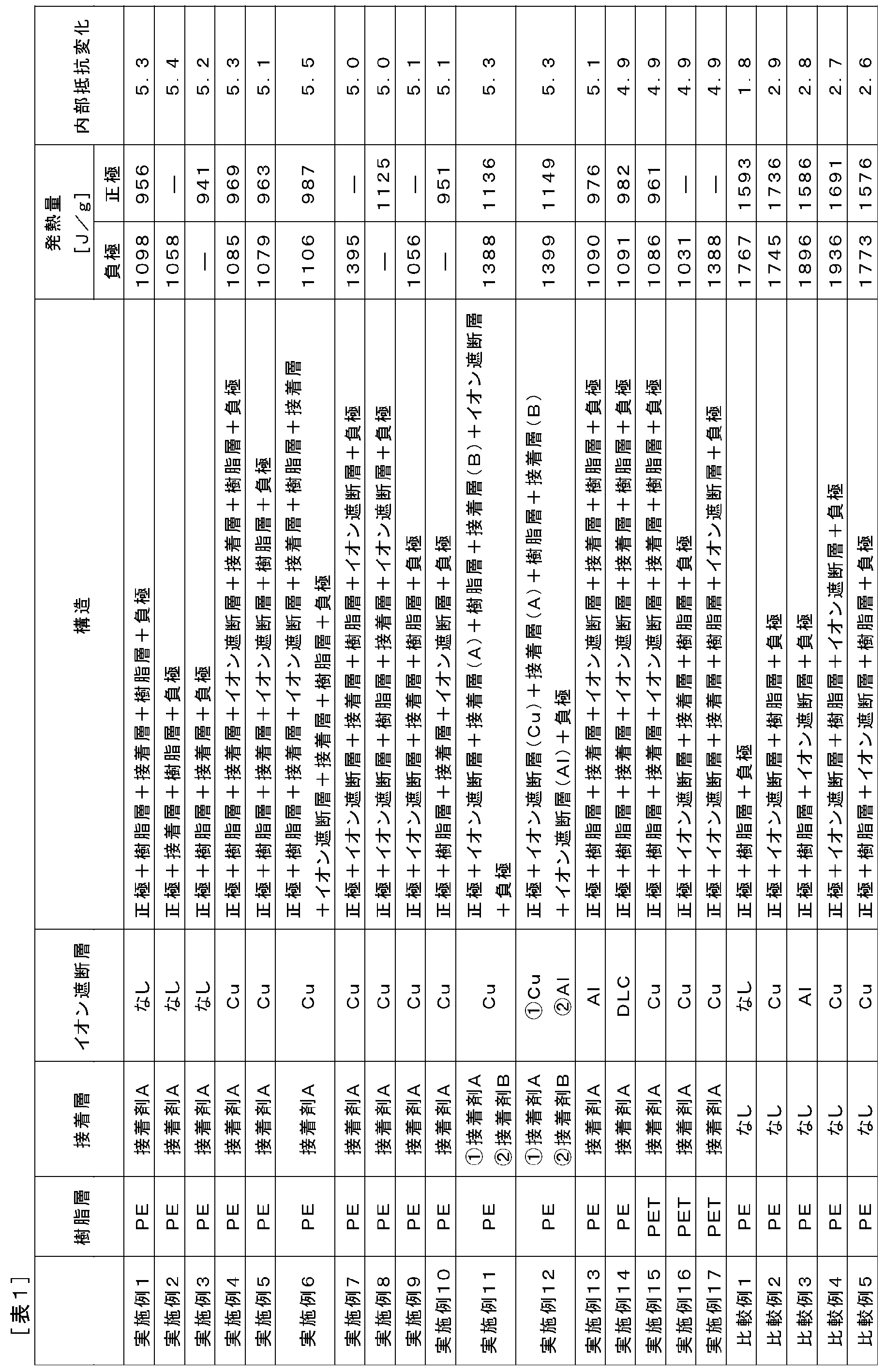
- bipolar electrodes were first produced using current collectors having different materials or laminated structures of the resin layer, the ion blocking layer, and the adhesive layer. And the bipolar secondary battery was produced using this bipolar electrode, and the internal resistance in low temperature and high temperature conditions was evaluated. The current collector and the laminate of the active material layer and the electrolyte were heated, and the amount of heat generated by the exothermic reaction between the active material layer and the electrolyte was evaluated.
- ⁇ Positive electrode active material slurry > 85% by mass of LiMn 2 O 4 as a positive electrode active material, 5% by mass of acetylene black as a conductive additive, 10% by mass of polyvinylidene fluoride (PVDF) as a binder, N-methyl-2-pyrrolidone (as a slurry viscosity adjusting solvent) NMP) was mixed in an appropriate amount to prepare a positive electrode active material slurry.
- PVDF polyvinylidene fluoride
- NMP N-methyl-2-pyrrolidone
- a negative electrode active material slurry was prepared by mixing 90% by mass of hard carbon as a negative electrode active material, 10% by mass of PVDF as a binder, and an appropriate amount of NMP as a slurry viscosity adjusting solvent.
- Example 1 As a resin layer having conductivity, a film having a thickness of 12.5 ⁇ m was prepared by adding 5% by mass of ketjen black to 100% by mass of polyethylene. Further, as a conductive adhesive, 20 mass% of carbon particles as a conductive material was added to thermally expandable microcapsules, and an adhesive A whose viscosity was adjusted using xylene was prepared. The thermally expandable microcapsules are formed by encapsulating hexane as an expanding material in a polyvinyl chloride shell (particle diameter 200 nm, melting point 125 ° C.). The adhesive A is applied to one surface of the resin layer so as to have a thickness of 2 ⁇ m, and another resin layer is laminated thereon and adhered to form a resin layer / adhesive layer / resin layer. A current collector was produced.
- the positive electrode active material slurry was applied to one surface of the obtained current collector, dried, and then pressed to form a positive electrode active material layer having a thickness of 36 ⁇ m. Moreover, after apply
- Example 2 As a resin layer having conductivity, a film having a thickness of 25 ⁇ m was prepared by adding 5% by mass of ketjen black to 100% by mass of polyethylene. The adhesive A was applied to one surface of the resin layer so as to have a thickness of 2 ⁇ m and dried to prepare a current collector composed of a resin layer and an adhesive layer.
- the positive electrode active material slurry was applied to the surface of the obtained current collector on the adhesive layer side, dried, and then pressed to form a positive electrode active material layer having a thickness of 36 ⁇ m. Further, the negative electrode active material slurry is applied to the surface of the current collector on the resin layer side, dried, and then pressed to form a negative electrode active material layer having a thickness of 30 ⁇ m. 3 (B)) was completed.
- Example 3 As a resin layer having conductivity, a film having a thickness of 25 ⁇ m was prepared by adding 5% by mass of ketjen black to 100% by mass of polyethylene. The adhesive A was applied to one surface of the resin layer so as to have a thickness of 2 ⁇ m and dried to prepare a current collector composed of a resin layer and an adhesive layer.
- the positive electrode active material slurry was applied to the surface of the obtained current collector on the resin layer side, dried, and then pressed to form a positive electrode active material layer having a thickness of 36 ⁇ m. Further, the negative electrode active material slurry is applied to the surface on the adhesive layer side of the current collector, dried, and then pressed to form a negative electrode active material layer having a thickness of 30 ⁇ m. 3 (C)) was completed.
- Example 4 As a resin layer having conductivity, a film having a thickness of 12 ⁇ m was prepared by adding 5% by mass of ketjen black to 100% by mass of polyethylene.
- the adhesive A was applied to one surface of the resin layer so as to have a thickness of 1 ⁇ m, and a copper foil having a thickness of 2 ⁇ m serving as an ion blocking layer was laminated thereon and adhered. Furthermore, the adhesive A is applied to the surface of the obtained laminate on the copper foil side so as to have a thickness of 1 ⁇ m, and another resin layer is laminated on the surface to adhere to the resin layer / adhesive layer.
- a current collector composed of an ion blocking layer, an adhesive layer, and a resin layer was produced.
- the positive electrode active material slurry was applied to one surface of the obtained current collector, dried, and then pressed to form a positive electrode active material layer having a thickness of 36 ⁇ m. Moreover, after apply
- Example 5 As a resin layer having conductivity, a film having a thickness of 12 ⁇ m was prepared by adding 5% by mass of ketjen black to 100% by mass of polyethylene. The adhesive A was applied to one surface of the resin layer so as to have a thickness of 1 ⁇ m, and a copper foil having a thickness of 2 ⁇ m serving as an ion blocking layer was laminated thereon and adhered. On the copper foil side surface of the laminate obtained, another resin layer was laminated and bonded by thermocompression bonding at 60 ° C., and a current collector comprising a resin layer / adhesive layer / ion blocking layer / resin layer was bonded. Produced.
- the positive electrode active material slurry was applied to the surface on the resin layer side in contact with the adhesive layer of the obtained current collector, dried, and then pressed to form a positive electrode active material layer having a thickness of 36 ⁇ m.
- the negative electrode active material slurry is applied to the surface of the current collector that is in contact with the ion blocking layer, dried, and then pressed to form a negative electrode active material layer having a thickness of 30 ⁇ m.
- a bipolar electrode (FIG. 3E) was completed.
- Example 6 As a resin layer having conductivity, a film having a thickness of 7 ⁇ m was prepared by adding 5% by mass of ketjen black to 100% by mass of polyethylene. The adhesive A was applied to one surface of the resin layer so as to have a thickness of 1 ⁇ m, and a copper foil having a thickness of 2 ⁇ m serving as an ion blocking layer was laminated thereon and adhered. The adhesive A was applied to the surface of the laminate on the copper foil side so as to have a thickness of 1 ⁇ m, and another resin layer was laminated thereon and adhered.
- a resin layer / adhesive layer / ion blocking layer A current collector composed of an adhesive layer, a resin layer, an adhesive layer, an ion blocking layer, an adhesive layer, and a resin layer was produced.
- the positive electrode active material slurry was applied to one surface of the obtained current collector, dried, and then pressed to form a positive electrode active material layer having a thickness of 36 ⁇ m. Moreover, after apply
- Example 7 As a resin layer having conductivity, a film having a thickness of 20 ⁇ m was prepared by adding 5% by mass of ketjen black to 100% by mass of polyethylene. The adhesive A was applied to one surface of the resin layer so as to have a thickness of 1 ⁇ m, and a copper foil having a thickness of 2 ⁇ m serving as an ion blocking layer was laminated thereon and adhered. Another layer of copper foil is laminated on the surface of the resulting laminate on the resin layer side and bonded by thermocompression bonding at 60 ° C., and a current collector comprising an ion blocking layer, an adhesive layer, a resin layer, and an ion blocking layer is bonded. Produced.
- a positive electrode active material layer having a thickness of 36 ⁇ m is formed by applying the positive electrode active material slurry to the surface on the side of the ion blocking layer in contact with the adhesive layer of the obtained current collector, drying it, and then pressing the slurry. did. Also, the negative electrode active material slurry is applied to the surface on the side of the ion blocking layer in contact with the resin layer of the current collector, dried, and then pressed to form a negative electrode active material layer having a thickness of 30 ⁇ m.
- a bipolar electrode (FIG. 3G) was completed.
- Example 8 As a resin layer having conductivity, a film having a thickness of 20 ⁇ m was prepared by adding 5% by mass of ketjen black to 100% by mass of polyethylene. The adhesive A was applied to one surface of the resin layer so as to have a thickness of 1 ⁇ m, and a copper foil having a thickness of 2 ⁇ m serving as an ion blocking layer was laminated thereon and adhered. Another layer of copper foil is laminated on the surface of the resulting laminate on the resin layer side and bonded by thermocompression bonding at 60 ° C., and a current collector comprising an ion blocking layer, an adhesive layer, a resin layer, and an ion blocking layer is bonded. Produced.
- the positive electrode active material slurry is applied to the surface on the side of the ion blocking layer in contact with the resin layer of the obtained current collector, dried, and then pressed to form a positive electrode active material layer having a thickness of 36 ⁇ m did.
- the negative electrode active material slurry is applied to the surface on the side of the ion blocking layer in contact with the adhesive layer of the current collector, dried, and then pressed to form a negative electrode active material layer having a thickness of 30 ⁇ m.
- a bipolar electrode ((H) in FIG. 3) was completed.
- Example 9 As a resin layer having conductivity, a film having a thickness of 25 ⁇ m was prepared by adding 5% by mass of ketjen black to 100% by mass of polyethylene. The adhesive A is applied to one surface of the resin layer so as to have a thickness of 1 ⁇ m, and a 2 ⁇ m-thick copper foil as an ion blocking layer is laminated on the surface to adhere to the ion blocking layer / adhesion. A current collector comprising a layer and a resin layer was produced.
- the positive electrode active material slurry was applied to the surface of the current collector on the side of the ion blocking layer, dried, and then pressed to form a positive electrode active material layer having a thickness of 36 ⁇ m. Further, the negative electrode active material slurry is applied to the surface of the current collector on the resin layer side, dried, and then pressed to form a negative electrode active material layer having a thickness of 30 ⁇ m. (I) in FIG. 3 was completed.
- Example 10 As a resin layer having conductivity, a film having a thickness of 25 ⁇ m was prepared by adding 5% by mass of ketjen black to 100% by mass of polyethylene. The adhesive A is applied to one surface of the resin layer so as to have a thickness of 1 ⁇ m, and a 2 ⁇ m-thick copper foil as an ion blocking layer is laminated on the surface to adhere to the ion blocking layer / adhesion. A current collector comprising a layer and a resin layer was produced.
- the positive electrode active material slurry was applied to the surface of the obtained current collector on the resin layer side, dried, and then pressed to form a positive electrode active material layer having a thickness of 36 ⁇ m. Also, the negative electrode active material slurry is applied to the surface of the current collector on the side of the ion blocking layer, dried, and then pressed to form a negative electrode active material layer having a thickness of 30 ⁇ m. ((J) in FIG. 3) was completed.
- Example 11 As a resin layer having conductivity, a film having a thickness of 20 ⁇ m was prepared by adding 5% by mass of ketjen black to 100% by mass of polyethylene. In addition to the adhesive A, 20% by mass of carbon particles as a conductive material was added to a modified olefin (polyethylene, melting point 120 ° C.) as a conductive adhesive, and the viscosity was adjusted using xylene. Adhesive B was prepared. The adhesive A was applied to one surface of the resin layer so as to have a thickness of 1 ⁇ m, and a copper foil having a thickness of 2 ⁇ m serving as an ion blocking layer was laminated thereon and adhered.
- a modified olefin polyethylene, melting point 120 ° C.
- the adhesive B is applied to the other surface of the resin layer so as to have a thickness of 1 ⁇ m, and a copper foil having a thickness of 2 ⁇ m as an ion blocking layer is laminated thereon and adhered, whereby an ion blocking layer is formed.
- a current collector composed of an adhesive layer (A), a resin layer, an adhesive layer (B), and an ion blocking layer was produced.
- the positive electrode active material slurry is applied to the surface on the side of the ion blocking layer in contact with the adhesive layer (B) of the obtained current collector, dried, and then pressed to obtain a positive electrode active material having a thickness of 36 ⁇ m. A layer was formed. Also, the negative electrode active material slurry is applied to the surface on the side of the ion blocking layer in contact with the adhesive layer (A) of the current collector, dried, and then pressed to form a negative electrode active material layer having a thickness of 30 ⁇ m. And a bipolar electrode ((K) in FIG. 3) was completed.
- Example 12 As a resin layer having conductivity, a film having a thickness of 20 ⁇ m was prepared by adding 5% by mass of ketjen black to 100% by mass of polyethylene.
- the adhesive A was applied to one surface of the resin layer so as to have a thickness of 1 ⁇ m, and an aluminum foil having a thickness of 2 ⁇ m as an ion blocking layer was laminated thereon and adhered.
- the adhesive B is applied to the other surface of the resin layer so as to have a thickness of 1 ⁇ m, and a copper foil having a thickness of 2 ⁇ m as an ion blocking layer is laminated thereon and adhered, whereby an ion blocking layer is formed.
- a current collector made of (Al), an adhesive layer (A), a resin layer, an adhesive layer (B), and an ion blocking layer (Cu) was produced.
- the positive electrode active material slurry was applied to the surface on the side of the obtained collector ion blocking layer (Cu), dried, and then pressed to form a positive electrode active material layer having a thickness of 36 ⁇ m. Further, the negative electrode active material slurry is applied to the surface of the current collector on the side of the ion blocking layer (Al), dried, and then pressed to form a negative electrode active material layer having a thickness of 30 ⁇ m.
- a bipolar electrode ((L) in FIG. 3) was completed.
- Example 13 A bipolar electrode ((M) in FIG. 3) was completed by the same method as in Example 4 except that an aluminum foil having a thickness of 2 ⁇ m was used as the ion blocking layer.
- Example 14 A bipolar electrode ((N) in FIG. 3) was completed in the same manner as in Example 4 except that a diamond-like carbon (DLC) foil having a thickness of 2 ⁇ m was used as the ion blocking layer.
- DLC diamond-like carbon
- Example 15 As a conductive resin layer, a bipolar electrode (see FIG. 5) was formed in the same manner as in Example 4 except that a 12 ⁇ m thick film obtained by adding 5% by mass of ketjen black to polyethylene terephthalate (PET) was used. 3 (O)) was completed.
- PET polyethylene terephthalate
- Example 16 As a conductive resin layer, a bipolar electrode (see FIG. 5) was formed in the same manner as in Example 9 except that a film having a thickness of 25 ⁇ m obtained by adding 5% by mass of ketjen black to polyethylene terephthalate (PET) was used. 3 (P)) was completed.
- PET polyethylene terephthalate
- Example 17 As a conductive resin layer, a bipolar electrode (see FIG. 5) was obtained in the same manner as in Example 7 except that a film having a thickness of 20 ⁇ m obtained by adding 5% by mass of ketjen black to polyethylene terephthalate (PET) was used. 3 (Q)) was completed.
- PET polyethylene terephthalate
- the positive electrode active material slurry was applied to one surface of the current collector, dried, and then pressed to form a positive electrode active material layer having a thickness of 36 ⁇ m.
- the negative electrode active material slurry was applied to the other surface of the current collector, dried, and then pressed to form a negative electrode active material layer having a thickness of 30 ⁇ m. (A)) was completed.
- a film having a thickness of 25 ⁇ m was prepared by adding 5% by mass of ketjen black to 100% by mass of polyethylene.
- a copper foil having a thickness of 2 ⁇ m as an ion blocking layer was superposed on one surface of the resin layer and bonded by heat fusion at 100 ° C., thereby producing a current collector composed of an ion blocking layer and a resin layer.
- the positive electrode active material slurry was applied to the surface of the current collector on the side of the ion blocking layer, dried, and then pressed to form a positive electrode active material layer having a thickness of 36 ⁇ m. Further, the negative electrode active material slurry is applied to the surface of the current collector on the resin layer side, dried, and then pressed to form a negative electrode active material layer having a thickness of 30 ⁇ m. (B) of FIG. 4 was completed.
- a resin layer having conductivity As a resin layer having conductivity, a film having a thickness of 25 ⁇ m in which 5% by mass of ketjen black was added to polyethylene was prepared. An aluminum foil having a thickness of 2 ⁇ m serving as an ion blocking layer was superposed on one surface of the resin layer and bonded by heat fusion at 100 ° C. to produce a current collector composed of an ion blocking layer and a resin layer.
- the positive electrode active material slurry was applied to the surface of the obtained current collector on the resin layer side, dried, and then pressed to form a positive electrode active material layer having a thickness of 36 ⁇ m. Also, the negative electrode active material slurry is applied to the surface of the current collector on the side of the ion blocking layer, dried, and then pressed to form a negative electrode active material layer having a thickness of 30 ⁇ m. ((C) of FIG. 4) was completed.
- a film having a thickness of 20 ⁇ m was prepared by adding 5% by mass of ketjen black to 100% by mass of polyethylene.
- An aluminum foil having a thickness of 2 ⁇ m as an ion blocking layer was layered on one surface of the resin layer and bonded by heat sealing at 100 ° C.
- a 2 ⁇ m-thick copper foil as an ion blocking layer is overlapped on the other surface of the resin layer and bonded by heat fusion at 100 ° C., and a current collector composed of an ion blocking layer, a resin layer, and an ion blocking layer.
- the body was made.
- the positive electrode active material slurry was applied to one surface of the obtained current collector, dried, and then pressed to form a positive electrode active material layer having a thickness of 36 ⁇ m.
- the negative electrode active material slurry was applied to the other surface of the current collector, dried, and then pressed to form a negative electrode active material layer having a thickness of 30 ⁇ m. (D)) was completed.
- a film having a thickness of 12.5 ⁇ m was prepared by adding 5% by mass of ketjen black to 100% by mass of polyethylene.
- An aluminum foil having a thickness of 2 ⁇ m as an ion blocking layer was layered on one surface of the resin layer and bonded by heat sealing at 100 ° C. Further, another current layer is laminated on the surface of the obtained laminate on the aluminum foil side and bonded by heat fusion at 100 ° C., and a current collector comprising a resin layer, an ion blocking layer, and a resin layer is bonded.
- the positive electrode active material slurry was applied to one surface of the obtained current collector, dried, and then pressed to form a positive electrode active material layer having a thickness of 36 ⁇ m.
- the negative electrode active material slurry was applied to the other surface of the current collector, dried, and then pressed to form a negative electrode active material layer having a thickness of 30 ⁇ m. (E)) was completed.
- LiPF 6 as a lithium salt is dissolved at a concentration of 1.0M in a PC-EC mixed solvent in which propylene carbonate (PC) and ethylene carbonate (EC) are mixed at 1: 1 (volume ratio) to prepare an electrolytic solution.
- PC propylene carbonate
- EC ethylene carbonate
- HFP hexafluoropropylene
- PVDF polyvinylidene fluoride
- the gel electrolyte was applied to the positive electrode active material layer and the negative electrode active material layer of the bipolar electrode, and the DMC was dried to obtain a bipolar electrode soaked with the gel electrolyte. Moreover, the gel polymer electrolyte layer was produced by apply
- the gel polymer electrolyte layer was placed on the positive electrode active material layer of the bipolar electrode, and a seal portion (made of epoxy resin) having a width of 12 mm was disposed around the bipolar electrode. After six layers of bipolar electrodes were laminated in this order, the single cell layers (total of 5 layers) were sealed by fusing by pressing (0.2 MPa, 160 ° C., 5 seconds) from the top and bottom of the seal part. .
- the obtained power generation element was sandwiched between aluminum tabs for current extraction (130 mm ⁇ 80 mm, thickness 100 ⁇ m), and vacuum sealed using an aluminum laminate film as an exterior material. This was hot-pressed using a hot press machine at a surface pressure of 1 kg / cm 2 and a heating temperature of 100 ° C. for 1 hour to cure the uncured seal portion and complete a bipolar secondary battery.
- Examples 1 to 17 had a marked increase in internal resistance due to temperature rise, as compared with Comparative Examples 1 to 5. This was considered to be due to the expansion of the adhesive layer in the thickness direction (lamination direction) by vaporizing the expansion material of the thermally expandable microcapsule constituting the adhesive layer as the temperature increased.
- Examples 1 to 17 it was shown that the amount of heat generated by the exothermic reaction between the positive electrode active material layer and / or the negative electrode active material layer and the electrolyte was significantly reduced as compared with Comparative Examples 1 to 5. This was thought to be due to the reduction in the amount of current flowing in the thickness direction (stacking direction) of the current collector as the internal resistance increased.
Landscapes
- Chemical & Material Sciences (AREA)
- Chemical Kinetics & Catalysis (AREA)
- Electrochemistry (AREA)
- General Chemical & Material Sciences (AREA)
- Engineering & Computer Science (AREA)
- Materials Engineering (AREA)
- Composite Materials (AREA)
- Manufacturing & Machinery (AREA)
- Secondary Cells (AREA)
- Cell Electrode Carriers And Collectors (AREA)
- Battery Electrode And Active Subsutance (AREA)
Abstract
Description
集電体は、正極活物質層が形成される一方の面から、負極活物質層が形成される他方の面への電子の移動を媒介する機能を有する。本発明の好ましい実施形態に係る集電体は、導電性を有する樹脂層(以下、単に「樹脂層」とも称する)および導電性を有する接着層(以下、単に「接着層」とも称する)を含む。さらに必要に応じて、イオン遮断層などの他の層をも含みうる。ただし、本発明の範囲はかような実施形態のみには限定されず、特許請求の範囲に規定される要件を満足する限り、これらの層を含まなくともすべての実施形態が本発明の範囲に包含されうる。
導電性を有する樹脂層1は、電子移動媒体としての機能を有することは勿論のこと、集電体の軽量化に寄与しうる。該樹脂層1は、高分子材料からなる基材、ならびに必要により導電性フィラーおよびその他の部材を含みうる。
導電性を有する接着層3は、集電体に含まれる各構成部材(各層)同士、または、集電体と集電体の表面に形成される活物質層とを接着させる機能を有する。さらに、本実施形態に係る接着層3は、接着層自身の融点よりも低い温度で集電体の積層方向に膨張する機能を有する。なお、本明細書において、「膨張する」とは、25℃での接着層の厚さ方向(積層方向)の厚さに対して、1.05倍以上の厚さとなることを意味する。
イオン遮断層5は、導電性を有するとともに、集電体内のイオン透過を防止する機能(隔壁(バリア性)機能)を有する。これにより、集電体の劣化を防ぎ、電池の耐久性を向上させることができる。
図2は、本発明の一実施形態である双極型二次電池の全体構造を模式的に表わした断面図である。図2に示す本実施形態の双極型二次電池10は、実際に充放電反応が進行する略矩形の発電要素21が、電池外装材であるラミネートフィルム29の内部に封止された構造を有する。
双極型電極は、集電体と、該集電体の表面に形成されてなる活物質層とを有する。より詳しくは、一つの集電体の一方の面に正極活物質層が形成され、他方の面に負極活物質層が形成される。活物質層は正極活物質または負極活物質を含み、必要に応じてその他の添加剤をさらに含む。本形態の双極型電極は、上述の集電体を用いることにより、電池温度の上昇を効果的に抑制することができる。
正極活物質層は正極活物質を含む。正極活物質は、放電時にイオンを吸蔵し、充電時にイオンを放出する組成を有する。好ましい一例としては、遷移金属とリチウムとの複合酸化物であるリチウム-遷移金属複合酸化物が挙げられる。具体的には、LiCoO2などのLi・Co系複合酸化物、LiNiO2などのLi・Ni系複合酸化物、スピネルLiMn2O4などのLi・Mn系複合酸化物、LiFeO2などのLi・Fe系複合酸化物およびこれらの遷移金属の一部を他の元素により置換したものなどが使用できる。これらリチウム-遷移金属複合酸化物は、反応性、サイクル特性に優れ、低コストな材料である。そのためこれらの材料を電極に用いることにより、出力特性に優れた電池を形成することが可能である。このほか、前記正極活物質としては、LiFePO4などの遷移金属とリチウムのリン酸化合物や硫酸化合物;V2O5、MnO2、TiS2、MoS2、MoO3などの遷移金属酸化物や硫化物;PbO2、AgO、NiOOHなど、を用いることもできる。上記正極活物質は、単独で使用されてもあるいは2種以上の混合物の形態で使用されてもよい。
負極活物質層は負極活物質を含む。負極活物質は、放電時にイオンを放出し、充電時にイオンを吸蔵できる組成を有する。負極活物質は、リチウムを可逆的に吸蔵および放出できるものであれば特に制限されないが、負極活物質の例としては、SiやSnなどの金属、あるいはTiO、Ti2O3、TiO2、もしくはSiO2、SiO、SnO2などの金属酸化物、Li4/3Ti5/3O4もしくはLi7MnNなどのリチウムと遷移金属との複合酸化物、Li-Pb系合金、Li-Al系合金、Li、または天然黒鉛、人造黒鉛、カーボンブラック、活性炭、カーボンファイバー、コークス、ソフトカーボン、もしくはハードカーボンなどの炭素材料などが好ましく挙げられる。また、負極活物質は、リチウムと合金化する元素を含むことが好ましい。リチウムと合金化する元素を用いることにより、従来の炭素系材料に比べて高いエネルギー密度を有する高容量および優れた出力特性の電池を得ることが可能となる。上記負極活物質は、単独で使用されてもあるいは2種以上の混合物の形態で使用されてもよい。
電解質層は、電極間でリチウムイオンの移動する際の媒体としての機能を有する。電解質層を構成する電解質に特に制限はなく、液体電解質、ならびに高分子ゲル電解質および高分子固体電解質などのポリマー電解質が適宜用いられうる。
シール部(絶縁層)は、集電体同士の接触や単電池層の端部における短絡を防止する機能を有する。シール部を構成する材料としては、絶縁性、固体電解質の脱落に対するシール性や外部からの水分の透湿に対するシール性(密封性)、電池動作温度下での耐熱性等を有するものであればよい。例えば、ウレタン樹脂、エポキシ樹脂、ポリエチレン樹脂、ポリプロピレン樹脂、ポリイミド樹脂、ゴム等が用いられうる。なかでも、耐蝕性、耐薬品性、作り易さ(製膜性)、経済性等の観点から、ポリエチレン樹脂やポリプロピレン樹脂が、絶縁層の構成材料として好ましく用いられる。
電池外装材としては、従来公知の金属缶ケースを用いることができるほか、発電要素を覆うことができる、アルミニウムを含むラミネートフィルムを用いた袋状のケースが用いられうる。該ラミネートフィルムには、例えば、ポリプロピレン、アルミニウム、ナイロンをこの順に積層してなる3層構造のラミネートフィルム等を用いることができるが、これらに何ら制限されるものではない。本形態では、高出力化や冷却性能に優れ、EV、HEV用等の大型機器用電池に好適に利用することができるラミネートフィルムが望ましい。
正極活物質としてLiMn2O4を85質量%、導電助剤としてアセチレンブラックを5質量%、バインダとしてポリフッ化ビニリデン(PVDF)を10質量%、スラリー粘度調整溶媒としてN-メチル-2-ピロリドン(NMP)を適量混合し、正極活物質スラリーを調製した。
負極活物質としてハードカーボンを90質量%、バインダとしてPVDFを10質量%、スラリー粘度調整溶媒としてNMPを適量混合し、負極活物質スラリーを調製した。
[実施例1]
導電性を有する樹脂層として、ポリエチレン100質量%に対してケッチェンブラックを5質量%添加した厚さ12.5μmのフィルムを準備した。また、導電性を有する接着剤として、熱膨張性マイクロカプセルに、導電性材料としてのカーボン粒子を20質量%添加し、キシレンを用いて粘度調整した接着剤Aを準備した。なお、該熱膨張性マイクロカプセルは、ポリ塩化ビニルのシェル(粒径200nm、融点125℃)に膨張材としてのヘキサンが内包されてなるものである。上記樹脂層の一方の面に上記接着剤Aを厚さ2μmとなるように塗布し、この上に上記樹脂層をもう1枚重ねて接着することによって、樹脂層・接着層・樹脂層からなる集電体を作製した。
導電性を有する樹脂層として、ポリエチレン100質量%に対してケッチェンブラックを5質量%添加した厚さ25μmのフィルムを準備した。上記樹脂層の一方の面に上記接着剤Aを厚さ2μmとなるように塗布、乾燥することによって、樹脂層・接着層からなる集電体を作製した。
導電性を有する樹脂層として、ポリエチレン100質量%に対してケッチェンブラックを5質量%添加した厚さ25μmのフィルムを準備した。上記樹脂層の一方の面に上記接着剤Aを厚さ2μmとなるように塗布、乾燥することによって、樹脂層・接着層からなる集電体を作製した。
導電性を有する樹脂層として、ポリエチレン100質量%に対してケッチェンブラックを5質量%添加した厚さ12μmのフィルムを準備した。上記樹脂層の一方の面に上記接着剤Aを厚さ1μmとなるように塗布し、この上にイオン遮断層としての厚さ2μmの銅箔を重ねて接着した。さらに、得られた積層体の銅箔側の面に上記接着剤Aを厚さ1μmとなるように塗布し、この上に樹脂層をもう1枚重ねて接着することによって、樹脂層・接着層・イオン遮断層・接着層・樹脂層からなる集電体を作製した。
導電性を有する樹脂層として、ポリエチレン100質量%に対してケッチェンブラックを5質量%添加した厚さ12μmのフィルムを準備した。上記樹脂層の一方の面に上記接着剤Aを厚さ1μmとなるように塗布し、この上にイオン遮断層としての厚さ2μmの銅箔を重ねて接着した。得られた積層体の銅箔側の面に、樹脂層をもう1枚重ねて60℃で熱圧着することにより接着し、樹脂層・接着層・イオン遮断層・樹脂層からなる集電体を作製した。
導電性を有する樹脂層として、ポリエチレン100質量%に対してケッチェンブラックを5質量%添加した厚さ7μmのフィルムを準備した。上記樹脂層の一方の面に上記接着剤Aを厚さ1μmとなるように塗布し、この上にイオン遮断層としての厚さ2μmの銅箔を重ねて接着した。この積層体の銅箔側の面に上記接着剤Aを厚さ1μmとなるように塗布し、この上に樹脂層をもう1枚重ねて接着した。得られた積層体の樹脂層側の面に、上記と同様の方法で、さらに接着剤A、銅箔、接着剤A、樹脂層を順次積層することによって、樹脂層・接着層・イオン遮断層・接着層・樹脂層・接着層・イオン遮断層・接着層・樹脂層からなる集電体を作製した。
導電性を有する樹脂層として、ポリエチレン100質量%に対してケッチェンブラックを5質量%添加した厚さ20μmのフィルムを準備した。上記樹脂層の一方の面に上記接着剤Aを厚さ1μmとなるように塗布し、この上にイオン遮断層としての厚さ2μmの銅箔を重ねて接着した。得られた積層体の樹脂層側の面に銅箔をもう1枚重ねて60℃で熱圧着することにより接着し、イオン遮断層・接着層・樹脂層・イオン遮断層からなる集電体を作製した。
導電性を有する樹脂層として、ポリエチレン100質量%に対してケッチェンブラックを5質量%添加した厚さ20μmのフィルムを準備した。上記樹脂層の一方の面に上記接着剤Aを厚さ1μmとなるように塗布し、この上にイオン遮断層としての厚さ2μmの銅箔を重ねて接着した。得られた積層体の樹脂層側の面に銅箔をもう1枚重ねて60℃で熱圧着することにより接着し、イオン遮断層・接着層・樹脂層・イオン遮断層からなる集電体を作製した。
導電性を有する樹脂層として、ポリエチレン100質量%に対してケッチェンブラックを5質量%添加した厚さ25μmのフィルムを準備した。上記樹脂層の一方の面に上記接着剤Aを厚さ1μmとなるように塗布し、この上にイオン遮断層としての厚さ2μmの銅箔を重ねて接着することにより、イオン遮断層・接着層・樹脂層からなる集電体を作製した。
導電性を有する樹脂層として、ポリエチレン100質量%に対してケッチェンブラックを5質量%添加した厚さ25μmのフィルムを準備した。上記樹脂層の一方の面に上記接着剤Aを厚さ1μmとなるように塗布し、この上にイオン遮断層としての厚さ2μmの銅箔を重ねて接着することにより、イオン遮断層・接着層・樹脂層からなる集電体を作製した。
導電性を有する樹脂層として、ポリエチレン100質量%に対してケッチェンブラックを5質量%添加した厚さ20μmのフィルムを準備した。また、接着剤Aとは別に、導電性を有する接着剤として、変性オレフィン(ポリエチレン系、融点120℃)に、導電性材料としてのカーボン粒子を20質量%添加し、キシレンを用いて粘度調整した接着剤Bを準備した。上記樹脂層の一方の面に上記接着剤Aを厚さ1μmとなるように塗布し、この上にイオン遮断層としての厚さ2μmの銅箔を重ねて接着した。さらに、上記樹脂層の他方の面に上記接着剤Bを厚さ1μmとなるように塗布し、この上にイオン遮断層としての厚さ2μmの銅箔を重ねて接着することにより、イオン遮断層・接着層(A)・樹脂層・接着層(B)・イオン遮断層からなる集電体を作製した。
導電性を有する樹脂層として、ポリエチレン100質量%に対してケッチェンブラックを5質量%添加した厚さ20μmのフィルムを準備した。上記樹脂層の一方の面に上記接着剤Aを厚さ1μmとなるように塗布し、この上にイオン遮断層としての厚さ2μmのアルミニウム箔を重ねて接着した。さらに、上記樹脂層の他方の面に上記接着剤Bを厚さ1μmとなるように塗布し、この上にイオン遮断層としての厚さ2μmの銅箔を重ねて接着することにより、イオン遮断層(Al)・接着層(A)・樹脂層・接着層(B)・イオン遮断層(Cu)からなる集電体を作製した。
イオン遮断層として厚さ2μmのアルミニウム箔を用いたことを除いては、実施例4と同様の方法で双極型電極(図3の(M))を完成させた。
イオン遮断層として厚さ2μmのダイヤモンドライクカーボン(DLC)箔を用いたことを除いては、実施例4と同様の方法で双極型電極(図3の(N))を完成させた。
導電性を有する樹脂層として、ポリエチレンテレフタレート(PET)にケッチェンブラックを5質量%添加した厚さ12μmのフィルムを用いたことを除いては、実施例4と同様の方法で双極型電極(図3の(O))を完成させた。
導電性を有する樹脂層として、ポリエチレンテレフタレート(PET)にケッチェンブラックを5質量%添加した厚さ25μmのフィルムを用いたことを除いては、実施例9と同様の方法で双極型電極(図3の(P))を完成させた。
導電性を有する樹脂層として、ポリエチレンテレフタレート(PET)にケッチェンブラックを5質量%添加した厚さ20μmのフィルムを用いたことを除いては、実施例7と同様の方法で双極型電極(図3の(Q))を完成させた。
ポリエチレン100質量%に対してケッチェンブラックを5質量%添加した厚さ20μmのフィルム(導電性を有する樹脂層)のみを集電体として用いた。
導電性を有する樹脂層として、ポリエチレン100質量%に対してケッチェンブラックを5質量%添加した厚さ25μmのフィルムを準備した。上記樹脂層の一方の面にイオン遮断層としての厚さ2μmの銅箔を重ねて100℃で熱融着することにより接着し、イオン遮断層・樹脂層からなる集電体を作製した。
導電性を有する樹脂層として、ポリエチレンにケッチェンブラックを5質量%添加した厚さ25μmのフィルムを準備した。上記樹脂層の一方の面にイオン遮断層としての厚さ2μmのアルミニウム箔を重ねて100℃で熱融着することにより接着し、イオン遮断層・樹脂層からなる集電体を作製した。
導電性を有する樹脂層として、ポリエチレン100質量%に対してケッチェンブラックを5質量%添加した厚さ20μmのフィルムを準備した。上記樹脂層の一方の面にイオン遮断層としての厚さ2μmのアルミニウム箔を重ねて100℃で熱融着することにより接着した。さらに、上記樹脂層の他方の面にイオン遮断層としての厚さ2μmの銅箔を重ねて100℃で熱融着することにより接着し、イオン遮断層・樹脂層・イオン遮断層からなる集電体を作製した。
導電性を有する樹脂層として、ポリエチレン100質量%に対してケッチェンブラックを5質量%添加した厚さ12.5μmのフィルムを準備した。上記樹脂層の一方の面にイオン遮断層としての厚さ2μmのアルミニウム箔を重ねて100℃で熱融着することにより接着した。さらに、得られた積層体のアルミニウム箔側の面に、樹脂層をもう1枚重ねて100℃で熱融着することにより接着し、樹脂層・イオン遮断層・樹脂層からなる集電体を作製した。
プロピレンカーボネート(PC)とエチレンカーボネート(EC)とを1:1(体積比)で混合したPC-EC混合溶媒に、リチウム塩であるLiPF6を1.0Mの濃度で溶解し、電解液を調製した。得られた電解液を90質量%、ホストポリマーとしてヘキサフルオロプロピレン(HFP)およびポリフッ化ビニリデン(PVDF)の混合物(HFP:PVDF=90:10(質量比))を10質量%、粘度調整溶媒として適量のジメチルカーボネート(DMC)を混合し、ゲル電解質を調製した。
上記ゲル電解質を、上記双極型電極の正極活物質層および負極活物質層に塗布し、DMCを乾燥させることで、ゲル電解質が染み込んだ双極型電極とした。また、上記ゲル電解質を、セパレータ(厚さ:20μm)の両面に塗布し、DMCを乾燥させることで、ゲルポリマー電解質層を作製した。
上記で作製した各双極型二次電池を、25℃の雰囲気下、定電流方式(CC、電流:0.5mA)で21.0Vまで充電し、その後、定電圧方式(CV、21V)で充電し、あわせて10時間充電した。その後、1Cの放電容量で放電した。この後、25℃での電池の内部抵抗を測定した。次に、該電池を130℃に加熱し、内部抵抗を測定した。そして、25℃における内部抵抗を1としたときの130℃における内部抵抗を算出した。結果を表1に示す。
上記で作製した各双極型二次電池をグローブボックス内で解体し、正極活物質層・集電体・負極活物質層からなる双極型電極を分離し、DMCで3回洗浄し、真空チャンバー内で乾燥させた。その後、正極活物質層・集電体からなる積層体または負極活物質層・集電体からなる積層体を1mgずつ切り出した。また、ECとジエチルカーボネート(DEC)とを2:3(体積比)で混合したEC-DEC混合溶液に、リチウム塩であるLiPF6を1.0Mの濃度で溶解し、電解液を調製した。そして、上記で切り出した積層体と該電解液とをSUS製金めっきパンに入れ、室温(25℃)~400℃の範囲の示差熱走査分析(DSC)により、活物質層と電解液との発熱反応によって生じた発熱量を測定した。結果を表1に示す。
3 接着層、
5 イオン遮断層、
10 双極型二次電池、
11 集電体、
11a 正極側の最外層集電体、
11b 負極側の最外層集電体、
13 正極活物質層、
15 負極活物質層、
17 電解質層、
19 単電池層、
21 発電要素、
23 双極型電極、
25 正極集電板、
27 負極集電板、
29 ラミネートフィルム、
31 シール部。
Claims (7)
- 導電性を有する双極型二次電池用集電体であって、
所定温度以上の温度で集電体の厚さ方向に膨張する膨張部を有することを特徴とする、双極型二次電池用集電体。 - 前記膨張部が、熱可塑性高分子材料を含むシェルに膨張材が内包されてなる熱膨張性マイクロカプセルを含む、請求項1に記載の双極型二次電池用集電体。
- 導電性を有する樹脂層と、
導電性を有し、前記樹脂層よりも低い融点を有する接着層と、が積層されてなり、
前記接着層が前記膨張部を含む、請求項1または2に記載の双極型二次電池用集電体。 - イオン遮断層をさらに含み、
前記接着層の一方の面と、前記イオン遮断層の一方の面とが互いに接する、請求項3に記載の双極型二次電池用集電体。 - 前記樹脂層を2層含み、
該2層の樹脂層が、それぞれ前記イオン遮断層の他方の面および前記接着層の他方の面に配置されてなる、請求項4に記載の双極型二次電池用集電体。 - 請求項1~5のいずれか1項に記載の双極型二次電池用集電体と、
前記集電体の一方の面に形成されてなる、正極活物質層と、
前記集電体の他方の面に形成されてなる、負極活物質層と、
を含む、双極型二次電池用電極。 - 請求項6に記載の双極型二次電池用電極と、
電解質層と、が積層されてなる発電要素を含む、双極型二次電池。
Priority Applications (8)
| Application Number | Priority Date | Filing Date | Title |
|---|---|---|---|
| CN201080051707.5A CN102687317B (zh) | 2009-11-20 | 2010-11-04 | 双极型二次电池用集电体 |
| JP2011541878A JP5177301B2 (ja) | 2009-11-20 | 2010-11-04 | 双極型二次電池用集電体 |
| BR112012012049-2A BR112012012049B1 (pt) | 2009-11-20 | 2010-11-04 | Coletor de corrente para bateria secundária bipolar, eletrodo para bateria secundária bipolar e bateria secundária bipolar |
| EP10831460.0A EP2503628B1 (en) | 2009-11-20 | 2010-11-04 | Current collector for bipolar secondary battery |
| US13/501,161 US9005807B2 (en) | 2009-11-20 | 2010-11-04 | Current collector for bipolar secondary battery |
| MX2012004859A MX2012004859A (es) | 2009-11-20 | 2010-11-04 | Colector de corriente para bateria secundaria bipolar. |
| RU2012125618/07A RU2544484C2 (ru) | 2009-11-20 | 2010-11-04 | Токосъемник для двухполюсной аккумуляторной батареи |
| KR1020127012830A KR101408389B1 (ko) | 2009-11-20 | 2010-11-04 | 쌍극형 2차 전지용 집전체 |
Applications Claiming Priority (2)
| Application Number | Priority Date | Filing Date | Title |
|---|---|---|---|
| JP2009265181 | 2009-11-20 | ||
| JP2009-265181 | 2009-11-20 |
Publications (1)
| Publication Number | Publication Date |
|---|---|
| WO2011062065A1 true WO2011062065A1 (ja) | 2011-05-26 |
Family
ID=44059547
Family Applications (1)
| Application Number | Title | Priority Date | Filing Date |
|---|---|---|---|
| PCT/JP2010/069610 WO2011062065A1 (ja) | 2009-11-20 | 2010-11-04 | 双極型二次電池用集電体 |
Country Status (9)
| Country | Link |
|---|---|
| US (1) | US9005807B2 (ja) |
| EP (1) | EP2503628B1 (ja) |
| JP (1) | JP5177301B2 (ja) |
| KR (1) | KR101408389B1 (ja) |
| CN (1) | CN102687317B (ja) |
| BR (1) | BR112012012049B1 (ja) |
| MX (1) | MX2012004859A (ja) |
| RU (1) | RU2544484C2 (ja) |
| WO (1) | WO2011062065A1 (ja) |
Cited By (14)
| Publication number | Priority date | Publication date | Assignee | Title |
|---|---|---|---|---|
| CN102683739A (zh) * | 2012-02-20 | 2012-09-19 | 宁德新能源科技有限公司 | 一种锂离子电池 |
| CN104254940A (zh) * | 2012-05-15 | 2014-12-31 | 株式会社Uacj | 集电体、电极结构体、非水电解质电池及蓄电部件、集电体的制造方法 |
| JP2015076182A (ja) * | 2013-10-07 | 2015-04-20 | 古河機械金属株式会社 | 電気素子および電気素子の製造方法 |
| RU2566741C2 (ru) * | 2011-07-26 | 2015-10-27 | Ниссан Мотор Ко., Лтд. | Токоотвод для биполярной литий-ионной аккумуляторной батареи |
| WO2016031690A1 (ja) * | 2014-08-25 | 2016-03-03 | 日産自動車株式会社 | 電極 |
| JPWO2016031688A1 (ja) * | 2014-08-25 | 2017-06-29 | 日産自動車株式会社 | 積層型電池およびその製造方法 |
| CN107305959A (zh) * | 2016-04-25 | 2017-10-31 | 松下知识产权经营株式会社 | 电池和电池制造方法以及电池制造装置 |
| JP2017199662A (ja) * | 2016-04-25 | 2017-11-02 | パナソニックIpマネジメント株式会社 | 電池、および、電池製造方法、および、電池製造装置 |
| JP2019079666A (ja) * | 2017-10-24 | 2019-05-23 | トヨタ自動車株式会社 | 非水電解質二次電池 |
| JP2019139914A (ja) * | 2018-02-08 | 2019-08-22 | 三洋化成工業株式会社 | 樹脂集電体、リチウムイオン電池用正極、及び、リチウムイオン電池 |
| JP2019139915A (ja) * | 2018-02-08 | 2019-08-22 | 三洋化成工業株式会社 | リチウムイオン電池用正極、及び、リチウムイオン電池 |
| WO2019189866A1 (ja) * | 2018-03-30 | 2019-10-03 | 三井化学株式会社 | マイクロカプセルを含むアンダーコート層を備えた正極及びリチウムイオン二次電池 |
| JP2019212384A (ja) * | 2018-05-31 | 2019-12-12 | 三洋化成工業株式会社 | 樹脂集電体、及び、リチウムイオン電池 |
| JP2022537472A (ja) * | 2020-05-20 | 2022-08-26 | 寧徳新能源科技有限公司 | 電池セル、前記電池セルが適用される電池および電子機器 |
Families Citing this family (24)
| Publication number | Priority date | Publication date | Assignee | Title |
|---|---|---|---|---|
| DE102010040574A1 (de) * | 2010-09-10 | 2012-03-15 | Fraunhofer-Gesellschaft zur Förderung der angewandten Forschung e.V. | Stromleiter für elektrochemische Zellen |
| JPWO2013172257A1 (ja) * | 2012-05-15 | 2016-01-12 | 株式会社Uacj | 集電体、電極構造体、非水電解質電池及び蓄電部品、集電体の製造方法 |
| DE102013204226A1 (de) * | 2013-03-12 | 2014-10-02 | Robert Bosch Gmbh | Ableiter für einen elektrochemischen Energiespeicher |
| WO2014159903A2 (en) * | 2013-03-13 | 2014-10-02 | Freya Energy, Inc. | Separator for electrochemical cell with overcharge protection and method of making same |
| US9461337B2 (en) * | 2013-03-13 | 2016-10-04 | Freya Energy, Inc. | Separator for electrochemical cell with thermally induced self-discharge intrinsic in the construction |
| JP6223725B2 (ja) * | 2013-06-12 | 2017-11-01 | 新光電気工業株式会社 | 電池及びその製造方法 |
| JPWO2015029084A1 (ja) * | 2013-08-27 | 2017-03-02 | 新日本金属鉱業株式会社 | 電極構造体及び二次電池 |
| WO2016031689A1 (ja) * | 2014-08-25 | 2016-03-03 | 日産自動車株式会社 | 電気的接続構造 |
| CN105810895A (zh) * | 2014-12-30 | 2016-07-27 | 苏州宝时得电动工具有限公司 | 正极以及含有正极的电池 |
| CN105390629A (zh) * | 2015-10-28 | 2016-03-09 | 广东烛光新能源科技有限公司 | 一种电化学电池及其制备方法 |
| PL3379622T3 (pl) | 2015-11-19 | 2022-10-31 | Zeon Corporation | Elektroda do akumulatora litowo-jonowego |
| JP6798505B2 (ja) * | 2015-12-28 | 2020-12-09 | 日本ゼオン株式会社 | リチウムイオン二次電池用感熱層 |
| CN107749450B (zh) * | 2016-10-19 | 2021-01-19 | 万向一二三股份公司 | 一种高安全性锂离子电池隔膜的制备方法 |
| JP6893457B2 (ja) * | 2017-09-13 | 2021-06-23 | 本田技研工業株式会社 | バイポーラ固体電池の集電板配置構造 |
| JP6816696B2 (ja) * | 2017-10-13 | 2021-01-20 | トヨタ自動車株式会社 | 負極、およびそれを備える非水電解質二次電池 |
| JP7149520B2 (ja) * | 2017-10-31 | 2022-10-07 | パナソニックIpマネジメント株式会社 | 電池及び電池スタック |
| CN108091825A (zh) * | 2017-11-16 | 2018-05-29 | 东莞市迈科新能源有限公司 | 一种锂离子电池极片及其电池 |
| JP6933149B2 (ja) * | 2018-01-22 | 2021-09-08 | トヨタ自動車株式会社 | 非水電解質二次電池 |
| JP6879289B2 (ja) * | 2018-12-13 | 2021-06-02 | トヨタ自動車株式会社 | 非水電解質二次電池 |
| CN110660957B (zh) * | 2018-12-29 | 2020-12-04 | 宁德时代新能源科技股份有限公司 | 一种电极极片和电化学装置 |
| CN110762205A (zh) * | 2019-10-23 | 2020-02-07 | 上海海洋大学 | 一种深海浮力材料应变测量的密封防护结构及制作方法 |
| JP7414813B2 (ja) * | 2020-09-23 | 2024-01-16 | 寧徳新能源科技有限公司 | 複合集電体、電極シート及び電気化学デバイス |
| CN112993206A (zh) * | 2021-02-05 | 2021-06-18 | 珠海冠宇电池股份有限公司 | 一种电极片及电化学储能装置 |
| CN113871626B (zh) * | 2021-09-06 | 2023-03-14 | 湖南领湃达志科技股份有限公司 | 一种二次电池双极集流体及其制造工艺 |
Citations (4)
| Publication number | Priority date | Publication date | Assignee | Title |
|---|---|---|---|---|
| JPS6255870A (ja) * | 1985-09-03 | 1987-03-11 | Japan Storage Battery Co Ltd | 電池用焼結基板の製造法 |
| JPS62100945A (ja) * | 1985-10-28 | 1987-05-11 | Shin Kobe Electric Mach Co Ltd | ニツケルカドミウムアルカリ蓄電池用焼結基板の製造方法 |
| JPH1050294A (ja) * | 1996-08-05 | 1998-02-20 | Sumitomo Bakelite Co Ltd | 熱敏感性抵抗体層付き蓄電素子 |
| JP2006190649A (ja) | 2004-12-07 | 2006-07-20 | Nissan Motor Co Ltd | バイポーラ電池およびその製造方法 |
Family Cites Families (11)
| Publication number | Priority date | Publication date | Assignee | Title |
|---|---|---|---|---|
| JPS6243061A (ja) * | 1985-08-20 | 1987-02-25 | Yuasa Battery Co Ltd | 酸化銀電池 |
| US5200281A (en) * | 1991-11-18 | 1993-04-06 | Westinghouse Electric Corp. | Sintered bipolar battery plates |
| RU2106724C1 (ru) * | 1996-09-30 | 1998-03-10 | Московский государственный авиационный институт (технический университет) | Кислородно(воздушно)-металлический механически перезаряжаемый химический источник тока |
| US6664006B1 (en) * | 1999-09-02 | 2003-12-16 | Lithium Power Technologies, Inc. | All-solid-state electrochemical device and method of manufacturing |
| JP4727021B2 (ja) * | 2000-05-22 | 2011-07-20 | 株式会社クレハ | 電極及びそれを用いた非水系電池 |
| US6503658B1 (en) * | 2001-07-11 | 2003-01-07 | Electro Energy, Inc. | Bipolar electrochemical battery of stacked wafer cells |
| GB0227705D0 (en) * | 2002-11-27 | 2003-01-08 | Danionics As | Electrochemical cell |
| JP2005011540A (ja) * | 2003-06-16 | 2005-01-13 | Toshiba Corp | 非水電解液二次電池 |
| CN100483831C (zh) * | 2004-12-07 | 2009-04-29 | 日产自动车株式会社 | 双极性电极电池组及其制备方法 |
| JP5114950B2 (ja) * | 2006-02-13 | 2013-01-09 | 日産自動車株式会社 | 電池モジュール、組電池及びそれらの電池を搭載した車両 |
| JP2008262785A (ja) | 2007-04-11 | 2008-10-30 | Matsushita Electric Ind Co Ltd | 非水電解質二次電池 |
-
2010
- 2010-11-04 CN CN201080051707.5A patent/CN102687317B/zh active Active
- 2010-11-04 RU RU2012125618/07A patent/RU2544484C2/ru active
- 2010-11-04 JP JP2011541878A patent/JP5177301B2/ja active Active
- 2010-11-04 MX MX2012004859A patent/MX2012004859A/es active IP Right Grant
- 2010-11-04 EP EP10831460.0A patent/EP2503628B1/en active Active
- 2010-11-04 KR KR1020127012830A patent/KR101408389B1/ko active IP Right Grant
- 2010-11-04 BR BR112012012049-2A patent/BR112012012049B1/pt active IP Right Grant
- 2010-11-04 US US13/501,161 patent/US9005807B2/en active Active
- 2010-11-04 WO PCT/JP2010/069610 patent/WO2011062065A1/ja active Application Filing
Patent Citations (4)
| Publication number | Priority date | Publication date | Assignee | Title |
|---|---|---|---|---|
| JPS6255870A (ja) * | 1985-09-03 | 1987-03-11 | Japan Storage Battery Co Ltd | 電池用焼結基板の製造法 |
| JPS62100945A (ja) * | 1985-10-28 | 1987-05-11 | Shin Kobe Electric Mach Co Ltd | ニツケルカドミウムアルカリ蓄電池用焼結基板の製造方法 |
| JPH1050294A (ja) * | 1996-08-05 | 1998-02-20 | Sumitomo Bakelite Co Ltd | 熱敏感性抵抗体層付き蓄電素子 |
| JP2006190649A (ja) | 2004-12-07 | 2006-07-20 | Nissan Motor Co Ltd | バイポーラ電池およびその製造方法 |
Non-Patent Citations (1)
| Title |
|---|
| See also references of EP2503628A4 |
Cited By (26)
| Publication number | Priority date | Publication date | Assignee | Title |
|---|---|---|---|---|
| US9537152B2 (en) | 2011-07-26 | 2017-01-03 | Nissan Motor Co., Ltd. | Collector for bipolar lithium ion secondary batteries |
| RU2566741C2 (ru) * | 2011-07-26 | 2015-10-27 | Ниссан Мотор Ко., Лтд. | Токоотвод для биполярной литий-ионной аккумуляторной батареи |
| CN102683739A (zh) * | 2012-02-20 | 2012-09-19 | 宁德新能源科技有限公司 | 一种锂离子电池 |
| CN104254940A (zh) * | 2012-05-15 | 2014-12-31 | 株式会社Uacj | 集电体、电极结构体、非水电解质电池及蓄电部件、集电体的制造方法 |
| JP2015076182A (ja) * | 2013-10-07 | 2015-04-20 | 古河機械金属株式会社 | 電気素子および電気素子の製造方法 |
| WO2016031690A1 (ja) * | 2014-08-25 | 2016-03-03 | 日産自動車株式会社 | 電極 |
| JPWO2016031688A1 (ja) * | 2014-08-25 | 2017-06-29 | 日産自動車株式会社 | 積層型電池およびその製造方法 |
| JPWO2016031690A1 (ja) * | 2014-08-25 | 2017-07-13 | 日産自動車株式会社 | 電極 |
| US10658674B2 (en) | 2014-08-25 | 2020-05-19 | Nissan Motor Co., Ltd. | Electrode |
| CN107305959A (zh) * | 2016-04-25 | 2017-10-31 | 松下知识产权经营株式会社 | 电池和电池制造方法以及电池制造装置 |
| JP2017199664A (ja) * | 2016-04-25 | 2017-11-02 | パナソニックIpマネジメント株式会社 | 電池、および、電池製造方法、および、電池製造装置 |
| JP2017199662A (ja) * | 2016-04-25 | 2017-11-02 | パナソニックIpマネジメント株式会社 | 電池、および、電池製造方法、および、電池製造装置 |
| CN107305959B (zh) * | 2016-04-25 | 2022-05-13 | 松下知识产权经营株式会社 | 电池和电池制造方法以及电池制造装置 |
| JP7018577B2 (ja) | 2016-04-25 | 2022-02-14 | パナソニックIpマネジメント株式会社 | 電池、および、電池製造方法、および、電池製造装置 |
| JP7018576B2 (ja) | 2016-04-25 | 2022-02-14 | パナソニックIpマネジメント株式会社 | 電池、および、電池製造方法、および、電池製造装置 |
| JP2019079666A (ja) * | 2017-10-24 | 2019-05-23 | トヨタ自動車株式会社 | 非水電解質二次電池 |
| JP2019139914A (ja) * | 2018-02-08 | 2019-08-22 | 三洋化成工業株式会社 | 樹脂集電体、リチウムイオン電池用正極、及び、リチウムイオン電池 |
| JP7007944B2 (ja) | 2018-02-08 | 2022-01-25 | 三洋化成工業株式会社 | リチウムイオン電池用正極、及び、リチウムイオン電池 |
| JP7042640B2 (ja) | 2018-02-08 | 2022-03-28 | 三洋化成工業株式会社 | 樹脂集電体、リチウムイオン電池用正極、及び、リチウムイオン電池 |
| JP2019139915A (ja) * | 2018-02-08 | 2019-08-22 | 三洋化成工業株式会社 | リチウムイオン電池用正極、及び、リチウムイオン電池 |
| CN111758174A (zh) * | 2018-03-30 | 2020-10-09 | 三井化学株式会社 | 具备包含微囊的底涂层的正极及锂离子二次电池 |
| WO2019189866A1 (ja) * | 2018-03-30 | 2019-10-03 | 三井化学株式会社 | マイクロカプセルを含むアンダーコート層を備えた正極及びリチウムイオン二次電池 |
| JP2019212384A (ja) * | 2018-05-31 | 2019-12-12 | 三洋化成工業株式会社 | 樹脂集電体、及び、リチウムイオン電池 |
| JP7148277B2 (ja) | 2018-05-31 | 2022-10-05 | 三洋化成工業株式会社 | 樹脂集電体、及び、リチウムイオン電池 |
| JP2022537472A (ja) * | 2020-05-20 | 2022-08-26 | 寧徳新能源科技有限公司 | 電池セル、前記電池セルが適用される電池および電子機器 |
| JP7273952B2 (ja) | 2020-05-20 | 2023-05-15 | 寧徳新能源科技有限公司 | 電池セル、前記電池セルが適用される電池および電子機器 |
Also Published As
| Publication number | Publication date |
|---|---|
| BR112012012049B1 (pt) | 2021-11-23 |
| EP2503628B1 (en) | 2020-01-08 |
| EP2503628A4 (en) | 2016-06-29 |
| EP2503628A1 (en) | 2012-09-26 |
| CN102687317B (zh) | 2015-03-04 |
| KR20120069772A (ko) | 2012-06-28 |
| RU2012125618A (ru) | 2013-12-27 |
| KR101408389B1 (ko) | 2014-06-17 |
| JP5177301B2 (ja) | 2013-04-03 |
| BR112012012049A2 (pt) | 2020-09-15 |
| MX2012004859A (es) | 2012-05-22 |
| US20120208082A1 (en) | 2012-08-16 |
| US9005807B2 (en) | 2015-04-14 |
| RU2544484C2 (ru) | 2015-03-20 |
| CN102687317A (zh) | 2012-09-19 |
| JPWO2011062065A1 (ja) | 2013-04-04 |
Similar Documents
| Publication | Publication Date | Title |
|---|---|---|
| JP5177301B2 (ja) | 双極型二次電池用集電体 | |
| JP5333576B2 (ja) | 双極型二次電池及びその製造方法 | |
| JP5770553B2 (ja) | 双極型リチウムイオン二次電池用集電体 | |
| JP5504708B2 (ja) | 双極型二次電池 | |
| JP5375978B2 (ja) | 双極型リチウムイオン二次電池用集電体 | |
| JP5458605B2 (ja) | 双極型二次電池 | |
| JP5957947B2 (ja) | 双極型電極およびこれを用いた双極型リチウムイオン二次電池 | |
| JP5381292B2 (ja) | 双極型電極およびこれを用いた双極型二次電池 | |
| KR20140079712A (ko) | 2차 전지 | |
| JP2017168270A (ja) | リチウムイオン二次電池 | |
| JP5402116B2 (ja) | 双極型リチウムイオン二次電池用集電体 | |
| JP2010244943A (ja) | 双極型二次電池 | |
| JP5593984B2 (ja) | 二次電池用集電体 | |
| JP2011171185A (ja) | 二次電池用集電体 | |
| JP5569229B2 (ja) | リチウムイオン二次電池のニッケル含有正極用集電体 |
Legal Events
| Date | Code | Title | Description |
|---|---|---|---|
| WWE | Wipo information: entry into national phase |
Ref document number: 201080051707.5 Country of ref document: CN |
|
| 121 | Ep: the epo has been informed by wipo that ep was designated in this application |
Ref document number: 10831460 Country of ref document: EP Kind code of ref document: A1 |
|
| DPE1 | Request for preliminary examination filed after expiration of 19th month from priority date (pct application filed from 20040101) | ||
| WWE | Wipo information: entry into national phase |
Ref document number: 13501161 Country of ref document: US |
|
| WWE | Wipo information: entry into national phase |
Ref document number: 2011541878 Country of ref document: JP |
|
| WWE | Wipo information: entry into national phase |
Ref document number: MX/A/2012/004859 Country of ref document: MX |
|
| WWE | Wipo information: entry into national phase |
Ref document number: 2010831460 Country of ref document: EP |
|
| ENP | Entry into the national phase |
Ref document number: 20127012830 Country of ref document: KR Kind code of ref document: A |
|
| WWE | Wipo information: entry into national phase |
Ref document number: 1186/KOLNP/2012 Country of ref document: IN |
|
| NENP | Non-entry into the national phase |
Ref country code: DE |
|
| WWE | Wipo information: entry into national phase |
Ref document number: 2012125618 Country of ref document: RU |
|
| REG | Reference to national code |
Ref country code: BR Ref legal event code: B01A Ref document number: 112012012049 Country of ref document: BR |
|
| WWE | Wipo information: entry into national phase |
Ref document number: 1201001997 Country of ref document: TH |
|
| REG | Reference to national code |
Ref country code: BR Ref legal event code: B01E Ref document number: 112012012049 Country of ref document: BR Free format text: APRESENTE A TRADUCAO SIMPLES DA FOLHA DE ROSTO DA CERTIDAO DE DEPOSITO DA PRIORIDADE REIVINDICADA; OU DECLARACAO DE QUE OS DADOS DO PEDIDO INTERNACIONAL ESTAO FIELMENTE CONTIDOS NA PRIORIDADE REIVINDICADA, CONTENDO TODOS OS DADOS IDENTIFICADORES (NUMERO DA PRIORIDADE, DATA, DEPOSITANTE E INVENTORES), CONFORME O PARAGRAFO UNICO DO ART. 25 DA RESOLUCAO 77/2013. CABE SALIENTAR NAO FOI POSSIVEL INDIVIDUALIZAR OS TITULARES DA CITADA PRIORIDADE, INFORMACAO NECESSARIA PARA O EXAME DA CESSAO DO DOCUMENTO DE PRIORIDADE, SE FOR O CASO. |
|
| ENP | Entry into the national phase |
Ref document number: 112012012049 Country of ref document: BR Kind code of ref document: A2 Effective date: 20120521 |