WO2011037124A1 - リチウム二次電池の正極集電積層体 - Google Patents
リチウム二次電池の正極集電積層体 Download PDFInfo
- Publication number
- WO2011037124A1 WO2011037124A1 PCT/JP2010/066370 JP2010066370W WO2011037124A1 WO 2011037124 A1 WO2011037124 A1 WO 2011037124A1 JP 2010066370 W JP2010066370 W JP 2010066370W WO 2011037124 A1 WO2011037124 A1 WO 2011037124A1
- Authority
- WO
- WIPO (PCT)
- Prior art keywords
- positive electrode
- current collector
- conductive
- electrode current
- protective layer
- Prior art date
- Legal status (The legal status is an assumption and is not a legal conclusion. Google has not performed a legal analysis and makes no representation as to the accuracy of the status listed.)
- Ceased
Links
Images


Classifications
-
- H—ELECTRICITY
- H01—ELECTRIC ELEMENTS
- H01M—PROCESSES OR MEANS, e.g. BATTERIES, FOR THE DIRECT CONVERSION OF CHEMICAL ENERGY INTO ELECTRICAL ENERGY
- H01M4/00—Electrodes
- H01M4/02—Electrodes composed of, or comprising, active material
- H01M4/64—Carriers or collectors
- H01M4/66—Selection of materials
-
- H—ELECTRICITY
- H01—ELECTRIC ELEMENTS
- H01M—PROCESSES OR MEANS, e.g. BATTERIES, FOR THE DIRECT CONVERSION OF CHEMICAL ENERGY INTO ELECTRICAL ENERGY
- H01M4/00—Electrodes
- H01M4/02—Electrodes composed of, or comprising, active material
- H01M4/64—Carriers or collectors
- H01M4/66—Selection of materials
- H01M4/668—Composites of electroconductive material and synthetic resins
-
- H—ELECTRICITY
- H01—ELECTRIC ELEMENTS
- H01M—PROCESSES OR MEANS, e.g. BATTERIES, FOR THE DIRECT CONVERSION OF CHEMICAL ENERGY INTO ELECTRICAL ENERGY
- H01M4/00—Electrodes
- H01M4/02—Electrodes composed of, or comprising, active material
- H01M4/13—Electrodes for accumulators with non-aqueous electrolyte, e.g. for lithium-accumulators; Processes of manufacture thereof
-
- H—ELECTRICITY
- H01—ELECTRIC ELEMENTS
- H01M—PROCESSES OR MEANS, e.g. BATTERIES, FOR THE DIRECT CONVERSION OF CHEMICAL ENERGY INTO ELECTRICAL ENERGY
- H01M4/00—Electrodes
- H01M4/02—Electrodes composed of, or comprising, active material
- H01M4/64—Carriers or collectors
- H01M4/66—Selection of materials
- H01M4/663—Selection of materials containing carbon or carbonaceous materials as conductive part, e.g. graphite, carbon fibres
-
- H—ELECTRICITY
- H01—ELECTRIC ELEMENTS
- H01M—PROCESSES OR MEANS, e.g. BATTERIES, FOR THE DIRECT CONVERSION OF CHEMICAL ENERGY INTO ELECTRICAL ENERGY
- H01M4/00—Electrodes
- H01M4/02—Electrodes composed of, or comprising, active material
- H01M4/64—Carriers or collectors
- H01M4/66—Selection of materials
- H01M4/665—Composites
- H01M4/667—Composites in the form of layers, e.g. coatings
-
- H—ELECTRICITY
- H01—ELECTRIC ELEMENTS
- H01M—PROCESSES OR MEANS, e.g. BATTERIES, FOR THE DIRECT CONVERSION OF CHEMICAL ENERGY INTO ELECTRICAL ENERGY
- H01M10/00—Secondary cells; Manufacture thereof
- H01M10/05—Accumulators with non-aqueous electrolyte
- H01M10/052—Li-accumulators
-
- Y—GENERAL TAGGING OF NEW TECHNOLOGICAL DEVELOPMENTS; GENERAL TAGGING OF CROSS-SECTIONAL TECHNOLOGIES SPANNING OVER SEVERAL SECTIONS OF THE IPC; TECHNICAL SUBJECTS COVERED BY FORMER USPC CROSS-REFERENCE ART COLLECTIONS [XRACs] AND DIGESTS
- Y02—TECHNOLOGIES OR APPLICATIONS FOR MITIGATION OR ADAPTATION AGAINST CLIMATE CHANGE
- Y02E—REDUCTION OF GREENHOUSE GAS [GHG] EMISSIONS, RELATED TO ENERGY GENERATION, TRANSMISSION OR DISTRIBUTION
- Y02E60/00—Enabling technologies; Technologies with a potential or indirect contribution to GHG emissions mitigation
- Y02E60/10—Energy storage using batteries
Definitions
- the present invention relates to a positive electrode current collector laminate of a lithium secondary battery, a positive electrode laminate, and further to a lithium secondary battery.
- a lithium secondary battery is composed of a positive electrode in which a positive electrode mixture layer containing a positive electrode active material such as a lithium-containing composite oxide is provided on a positive electrode current collector such as an aluminum foil, and a negative electrode current collector such as an aluminum foil.
- a negative electrode provided with a negative electrode mixture layer containing a negative electrode active material such as a carbonaceous material, and a nonaqueous electrolytic solution containing an electrolyte salt such as a lithium salt and an organic solvent are provided.
- the positive electrode current collector is anodized and corroded due to the action of an electrolyte such as a lithium salt contained in the electrolytic solution, and the cycle characteristics and battery capacity are deteriorated. There is.
- Patent Document 1 proposes forming a surface protective layer containing a heterocyclic compound such as triazoles and coumarins on the current collector.
- Patent Document 2 describes the use of an epoxy resin as a binder.
- Patent Document 2 proposes that a protective layer containing at least one material selected from precious metals, alloys, conductive ceramics, semiconductors, organic semiconductors, and conductive polymers is formed on a current collector.
- the conductive polymer include polyaniline, polypyrrole, polyacene, polydisulfide, and polyparaphenylene.
- One method of forming a protective layer using a conductive polymer is to cast or apply a mixed solution in which a conductive polymer, a binder, and dopan (aromatic sulfonic acid ester) are dissolved in a solvent, and then heat and dry. Illustrated.
- Patent Document 3 proposes a polyvinylidene fluoride, polyacrylic acid, polypropylene, and the like as a binder for the conductive protective film formed on the negative electrode current collector, although it is an invention related to the negative electrode current collector. Yes.
- the surface protective layer of the heterocyclic compound described in Patent Document 1 is insufficient in terms of oxidation potential, and the materials described in Patent Document 2 and Patent Document 3 have a hard electrode.
- the material described in Patent Document 3 is effective in preventing corrosion of the aluminum foil, but is insufficient when used at a high voltage.
- An object of the present invention is to provide a positive electrode current collector laminate and a lithium secondary battery capable of protecting the positive electrode current collector from corrosion without impairing battery characteristics even in a high voltage specification.
- the present invention relates to a positive electrode current collector laminate in which a conductive protective layer (B) containing a fluororesin (b1) and a conductive filler (b2) is provided on the positive electrode current collector (A).
- a positive electrode laminate in which the positive electrode mixture layer (C) is provided on the conductive protective layer (B) of the positive electrode current collector laminate of the present invention, and further includes a positive electrode, a negative electrode, and a non-aqueous electrolyte
- the present invention also relates to a lithium secondary battery in which the positive electrode is the positive electrode current collecting laminate of the present invention.
- the present invention it is possible to provide a positive electrode current collector laminate and a lithium secondary battery that can protect the positive electrode current collector from corrosion without impairing battery characteristics even in a high voltage specification.
- FIG. 26 is a schematic assembly perspective view of a laminate cell manufactured in Examples 25 to 27.
- FIG. 6 is a schematic plan view of a laminate cell produced in Examples 25 to 27.
- the positive electrode current collector laminate of the present invention comprises a positive electrode current collector (A) provided with a conductive protective layer (B) containing a fluororesin (b1) and a conductive filler (b2).
- Positive electrode current collector As a material constituting the positive electrode current collector, for example, the surface of aluminum or its alloy, stainless steel, nickel or its alloy, titanium or its alloy, aluminum or stainless steel is treated with carbon or titanium. Used. Among these, aluminum and aluminum alloys are mentioned as positive electrode current collectors that are particularly protected. These materials can also be used after oxidizing the surface. Further, it is preferable that the surface of the current collector is roughened to improve the adhesion.
- the thickness of the positive electrode current collector is usually in the range of 5 to 30 ⁇ m.
- the positive electrode current collector laminate of the present invention is provided with a conductive protective layer (B) containing a fluororesin (b1) and a conductive filler (b2) on the current collector (A). ing.
- the fluorine resin (b1) can be used without particular limitation as long as it is not susceptible to oxidation.
- a fluorine resin (VdF resin) containing a structural unit derived from vinylidene fluoride (VdF), a fluorine atom in the side chain Acrylate / methacrylate containing tetrafluoroethylene (TFE) and a copolymer of hydrocarbon vinyl ether / vinyl ester.
- VdF resin containing a structural unit derived from vinylidene fluoride (VdF), a fluorine atom in the side chain Acrylate / methacrylate containing tetrafluoroethylene (TFE) and a copolymer of hydrocarbon vinyl ether / vinyl ester.
- a VdF-based resin is preferable because it is easy to contain a conductive filler, is excellent in oxidation resistance, and easily maintains flexibility.
- VdF resin examples include polyvinylidene fluoride (PVdF), which is a VdF homopolymer, and copolymers of VdF with other fluorine monomers and / or non-fluorine monomers.
- PVdF polyvinylidene fluoride
- fluorine monomers include, for example, TFE, hexafluoropropylene (HFP), fluoroalkyl vinyl ether, perfluoro (alkyl vinyl ether) (PAVE), chlorotrifluoroethylene (CTFE), trifluoroethylene, trifluoropropylene, tetrafluoro.
- fluorine-containing monomers such as propylene, pentafluoropropylene, trifluorobutene, tetrafluoroisobutene, vinyl fluoride, and iodine-containing fluorinated vinyl ether.
- non-fluorine monomer include ethylene (Et), propylene (Pr), alkyl vinyl ether and the like. One or two or more of these fluorine-containing monomers and non-fluorine-containing monomers can be used.
- At least one of PVdF, TFE / VdF copolymer, TFE / VdF / HFP copolymer, and VdF / HFP copolymer is preferable from the viewpoint of good flexibility and oxidation resistance.
- a copolymer containing TFE and VdF is preferable because of its low swellability with an electrolytic solution.
- the conductive filler (b2) used in the present invention refers to a filler having a volume resistivity of 1 ⁇ 10 ⁇ 9 to 1 ⁇ ⁇ cm.
- a preferred volume resistivity is 1 ⁇ 10 ⁇ 8 to 1 ⁇ 10 ⁇ 1 ⁇ ⁇ cm.
- Examples of the conductive filler (b2) include a conductive carbon filler.
- These conductive fillers may be particulate fillers, fibrous fillers, or combinations thereof.
- the particulate carbon filler examples include ketjen black, acetylene black, nanoporous carbon, graphite (natural graphite, artificial graphite), furnace black, channel black, etc.
- the chemical resistance and conductivity are good, and the composition From the viewpoint of good fluidity, nanoporous carbon and graphite are preferred, and from the viewpoint of good chemical resistance and electrical conductivity, ketjen black and acetylene black are preferred.
- the average primary particle diameter is preferably 0.002 to 20 ⁇ m, and more preferably 0.025 to 10 ⁇ m from the viewpoint of good conductivity.
- the fibrous carbon filler examples include carbon fibers, carbon nanotubes, and carbon nanofibers. Among them, carbon nanotubes and carbon nanofibers are preferable from the viewpoint of good conductivity, and carbon fibers are preferable from the viewpoint of cost performance. preferable.
- the diameter of the fibrous carbon is preferably 20 ⁇ m or less, more preferably 0.1 to 16 ⁇ m, and particularly preferably 1 to 15 ⁇ m from the viewpoint of good conductivity. Further, the ratio of average fiber length / average fiber diameter is preferably 5 or more, and more preferably 10 or more from the viewpoint of good conductivity. Moreover, it is preferable that it is 1000 or less, Furthermore, 500 or less from the point which preparation of a composition is easy.
- the filler to be blended is preferably a filler that is at least one selected from the group consisting of ketjen black, acetylene black, nanoporous carbon, graphite, carbon fiber, carbon nanotube, and carbon nanofiber.
- the particulate carbon filler and the fibrous carbon filler may be used in combination. When used in combination, for example, it becomes easier to control the aspect ratio of the conductivity of the protective layer, which will be described later, and the conductivity of the protective layer is further improved than when it is used alone.
- the mixing ratio of the particulate carbon filler / fibrous carbon filler the particulate carbon filler is preferably 10% by mass or more, more preferably 20% by mass or more from the viewpoint of giving good fluidity to the composition. It is preferably 90% by mass or less, more preferably 80% by mass or less from the viewpoint of easy control of the conductive aspect ratio in the protective layer.
- the compounding amount of the conductive filler (b2) is 5 to 300 parts by mass with respect to 100 parts by mass of the fluororesin (b1).
- the amount is less than 5 parts by mass, the conductivity of the protective layer becomes insufficient, which is not preferable.
- the amount exceeds 300 parts by mass the preparation of the composition becomes difficult, which is not preferable.
- a preferred lower limit is 5 parts by mass from the viewpoint of good conductivity of the protective layer.
- a preferable upper limit is 200 parts by mass from the viewpoint of good stability during molding, and 100 parts by mass from the viewpoint of easy preparation of the composition. Within this range, a conductive carbon filler and a metal filler may be used in combination.
- a non-conductive (volume resistivity exceeds 1 ⁇ ⁇ cm) filler may be used in combination.
- the nonconductive filler include a nonconductive carbon filler, a nonconductive inorganic oxide filler, and a nonconductive resin filler. Specifically, non-conductive carbon black, non-conductive Austin black, non-conductive graphite (natural graphite, artificial graphite), non-conductive carbon nanotube, non-conductive graphitized carbon black, etc.
- Carbon filler non-conductive such as silica, silicate, clay, diatomaceous earth, montmorillonite, talc, calcium carbonate, calcium silicate, barium sulfate, fatty acid calcium, titanium oxide, bengara, boron nitride, aluminum nitride, magnesium oxide, alumina
- Inorganic oxide filler polyethylene, heat-resistant engineering plastics, PTFE-based tetrafluoroethylene-ethylene-ethylene-tetrafluoroethylene copolymer (ETFE), fluorocarbons such as polyvinylidene fluoride (PVdF) Rimmer, such as a non-conductive resin filler such as polyimide and the like.
- the blending amount may be appropriately selected in consideration of the effect of blending, the degree and weight of conductivity of the conductive filler (b2), the elasticity and flexibility of the generated conductive protective layer, and the like.
- Other components include (b3-1) rubber fine particles for imparting flexibility, (b3-2) an adhesive for improving the adhesion between the current collector and the conductive layer, and (b3-3) fluororesin (B3-4) Surfactant that improves the dispersibility of the conductive filler and improves the leveling property of the paint.
- the rubber fine particles (b3-1) fluorine-based or non-fluorinated rubber particles, and further crosslinked rubber particles are preferable.
- fluorine-based rubber examples include VdF-based copolymer elastomers and TFE-based copolymer elastomers.
- non-fluorine rubber examples include acrylic rubber, SBR rubber, HNBR rubber, and nitrile rubber.
- Examples of the adhesive (b3-2) include an epoxy resin, a phenol resin, a silane coupling agent, and a urethane resin.
- Examples of the coupling agent or the crosslinking agent (b3-3) include a silane coupling agent and a urethane-based crosslinking agent.
- surfactant (b3-4) examples include anionic, nonionic and cationic surfactants.
- the conductive protective layer (B) in the present invention comprises a protective layer-forming composition containing a fluororesin (b1), a conductive filler (b2), and, if necessary, another component (b3) as a positive electrode current collector (A ) To form.
- the protective layer forming composition may be a coating composition or a molding composition.
- a coating composition in the case of a coating composition, it contains a fluororesin (b1), a conductive filler (b2), and, if necessary, a solvent (b4) in addition to other components (b3).
- the solvent (b4) may be an organic solvent or an aqueous solvent.
- organic solvent examples include ketones such as methyl ethyl ketone, acetone, cyclohexanone, and dibutyl ketone; amides such as N-methylpyrrolidone, dimethylacetamide, and dimethylformamide; butyl acetate, amyl acetate, butyl propionate, ethyl cellosolve, methyl cellosolve, and the like
- polar solvents such as ethers such as tetrahydrofuran, diglyme and triglyme.
- aqueous solvent water is representative, but alcohols and ketones may be used in combination. In this case, an emulsion-type coating composition is obtained.
- the blending ratio of the fluororesin (b1) and the conductive filler (b2) in the coating composition is the ratio described in the protective layer.
- the quantity of a solvent (b4) should just be an quantity used as the density
- the coating composition may be prepared by mixing each component by a normal mixing method employed in a coating composition using a resin.
- the method for forming the coating film may be a conventionally known method. For example, by applying to the substrate by roller coating method, brush coating method, dip coating method, spray coating method, gravure coating method, coil coating method, curtain flow coating method, etc., and then naturally drying or heating drying at ambient temperature Form a coating film.
- the fluororesin (b1) and the conductive filler (b2) and, if necessary, other components (b3) and the solvent (b4) are used in a usual manner. Can be made into a slurry.
- the conductive protective layer (B) thus obtained can control the volume resistivity in the range of 0.001 to 50 ⁇ ⁇ cm, and if necessary, 0.001 to 10 ⁇ ⁇ cm, further 1 ⁇ ⁇ cm or less.
- a highly conductive protective layer can be provided.
- the thickness of the conductive protective layer (B) may be appropriately selected within the range of 0.1 to 50 ⁇ m. For example, from the viewpoint of reducing resistance, it is 0.5 ⁇ m or more, more preferably 1.0 ⁇ m or more. From the point of manufacture, 50 micrometers or less, Furthermore, 10 micrometers or less are preferable.
- the current collector laminate of the present invention is highly effective when used for a positive electrode in which the current collector is severely corroded.
- the current collector configured as described above may also be applied to the negative electrode current collector.
- the present invention also relates to a positive electrode laminate in which the positive electrode mixture layer (C) is provided on the conductive protective layer (B) of the positive electrode current collector laminate of the present invention.
- the positive electrode mixture forming the positive electrode mixture layer (C) contains a positive electrode active material and a binder, and if necessary, is prepared by blending other materials.
- a conventionally known positive electrode mixture can be used, but it is particularly effective in the case of a positive electrode mixture having a high voltage specification.
- a lithium-containing transition metal composite oxide that produces a high voltage is particularly preferable.
- Formula (2) Li a Mn 2 -b M 1 b O 4 (where 0.9 ⁇ a; 0 ⁇ b ⁇ 1.5; M 1 is selected from the group consisting of Fe, Co, Ni, Cu, Zn, Al, Sn, Cr, V, Ti, Mg, Ca, Sr, B, Ga, In, Si and Ge Lithium-manganese spinel composite oxide represented by the formula (3): LiNi 1-c M 2 c O 2 (where 0 ⁇ c ⁇ 0.5; M 2 is Fe, Lithium represented by at least one metal selected from the group consisting of Co, Mn, Cu, Zn, Al, Sn, Cr, V, Ti, Mg, Ca, Sr, B, Ga, In, Si, and Ge) nickel composite oxide, or LiCo in 1-d M 3 d O 2 ( wherein, 0 ⁇ d ⁇ 0.5; M 3 At least
- LiCoO 2 , LiMnO 2 , LiNiO 2 , LiMn 2 O 4 , LiNi 0.8 Co 0.15 Al 0.05 O 2 , or LiNi 1/3 Co 1/3 Mn 1/3 O 2 has an energy density. It is preferable in that a high and high output lithium secondary battery can be provided.
- a positive electrode active material such as LiFePO 4 , LiNi 0.8 Co 0.2 O 2 , Li 1.2 Fe 0.4 Mn 0.4 O 2 , LiNi 0.5 Mn 0.5 O 2 , LiV 3 O 6 may be used.
- the compounding amount of the positive electrode active material is preferably 50 to 99% by mass, more preferably 80 to 99% by mass of the positive electrode mixture, from the viewpoint of high battery capacity.
- binder examples include fluorine resin, non-fluorine resin, and rubber.
- fluororesin examples include polytetrafluoroethylene (PTFE) and polyvinylidene fluoride (PVdF).
- PTFE polytetrafluoroethylene
- PVdF polyvinylidene fluoride
- the PTFE may be a tetrafluoroethylene homopolymer or a modified PTFE obtained by copolymerizing a small amount of other monomers such as HFP and PAVE.
- non-fluorinated resins include polyacrylic acid.
- examples of the rubber include ethylene / propylene / diene copolymer rubber (EPDM) and styrene / butadiene copolymer rubber (SBR).
- the blending amount of the binder is preferably 0.5 to 15% by mass, more preferably 0.5 to 10% by mass of the positive electrode mixture from the viewpoint of high battery capacity.
- Other components include fluorine resins such as TFE / HFP copolymer resins and ETFE and VdF copolymer resins for improving the adhesion of the positive electrode mixture and improving the utilization ratio of the positive electrode active material; Fluorine rubber and acrylic rubber for improving the resistance; Cellulosic resins such as cellulose acetate for improving the withstand voltage; Additives used in the production of electrodes of lithium secondary batteries, for example, conductive materials, thickening for electrode production Agents, other polymers, surfactants, and the like.
- the conductive material include conductive carbon black such as acetylene black and ketjen black; and carbonaceous materials such as graphite and carbon fiber.
- the positive electrode mixture layer (C) is appropriately mixed using an appropriate solvent, and a positive electrode mixture forming composition is prepared as a uniform mixture. It can carry out by methods, such as a spin coat, a blade coat, a roll coat, and a dip coat, on a property protection layer (B).
- the dried electrode is usually further rolled if necessary, then cut and processed to a predetermined thickness and size to obtain a positive electrode for a lithium secondary battery.
- the rolling process and the cutting process may be ordinary methods.
- the positive electrode current collector (A) is protected from the lithium salt in the electrolytic solution by the conductive protective layer (B), corrosion of the current collector can be suppressed even at a high operating voltage, The battery characteristics such as cycle characteristics can be prevented from being deteriorated, and the flexibility of the electrode is improved. Even when wound like a wound type lithium secondary battery, cracking and dropping do not occur.
- the present invention also relates to a lithium secondary battery.
- the lithium secondary battery of the present invention includes a positive electrode, a negative electrode, and a non-aqueous electrolyte, and uses the positive electrode laminate of the present invention as the positive electrode. Further, the current collector having the structure of the present invention may be applied to the negative electrode current collector.
- an electrode having a configuration other than the positive electrode current collector laminate of the present invention is used for the negative electrode
- a conventionally known electrode can be used for the negative electrode.
- the non-aqueous electrolyte is not particularly limited as long as it is an electrolyte containing an electrolyte salt and an organic solvent for dissolving the electrolyte salt and is used in a lithium secondary battery.
- Examples of the electrolyte include known electrolyte salts such as LiPF 6 , LiBF 4 , LiN (SO 2 CF 3 ) 2 , and LiN (SO 2 C 2 F 5 ) 2.
- Examples of the organic solvent include ethylene carbonate and dimethyl Hydrocarbon solvents such as carbonate, methyl ethyl carbonate, diethyl carbonate, propylene carbonate; fluorine solvents such as HCF 2 CF 2 CH 2 OCF 2 CF 2 H, CF 3 COOCF 3 , CF 3 COOCH 2 CF 3 , and mixtures thereof Although a solvent etc. can be illustrated, it is not limited only to these.
- Examples of the negative electrode active material constituting the negative electrode include carbon materials, and also include metal oxides and metal nitrides capable of inserting lithium ions.
- Examples of carbon materials include natural graphite, artificial graphite, pyrolytic carbons, cokes, mesocarbon microbeads, carbon fibers, activated carbon, and pitch-coated graphite.
- Metal oxides capable of inserting lithium ions include tin and Examples of the metal compound include silicon and titanium, such as tin oxide, silicon oxide, and lithium titanate.
- Examples of the metal nitride include Li 2.6 Co 0.4 N.
- the compounding amount of the negative electrode active material is preferably 50 to 99% by mass, more preferably 80 to 99% by mass of the negative electrode mixture, from the viewpoint of high battery capacity.
- a separator may be disposed in the lithium secondary battery of the present invention.
- the separator is not particularly limited, and is a microporous polyethylene film, a microporous polypropylene film, a microporous ethylene-propylene copolymer film, a microporous polypropylene / polyethylene bilayer film, or a microporous polypropylene / polyethylene / polypropylene trilayer film.
- a film in which an aramid resin is coated on a separator made for the purpose of improving safety such as a short circuit caused by Li dentrite, or a film in which a resin containing polyamideimide and an alumina filler is coated on a separator can be given (for example, (See JP 2007-299612 A and JP 2007-324073 A).
- the lithium secondary battery of the present invention is useful as a large-sized lithium secondary battery for a hybrid vehicle or a distributed power source, a small-sized lithium secondary battery such as a mobile phone or a portable information terminal.
- the measurement method and evaluation method employed in the present invention are as follows.
- volume resistivity The volume resistivity is measured by the following method. Although the volume resistivity is measured for the laminate, the volume resistivity of the current collector is negligible compared to the volume resistivity of the conductive protective layer. It is regarded as the volume resistivity of the conductive protective layer.
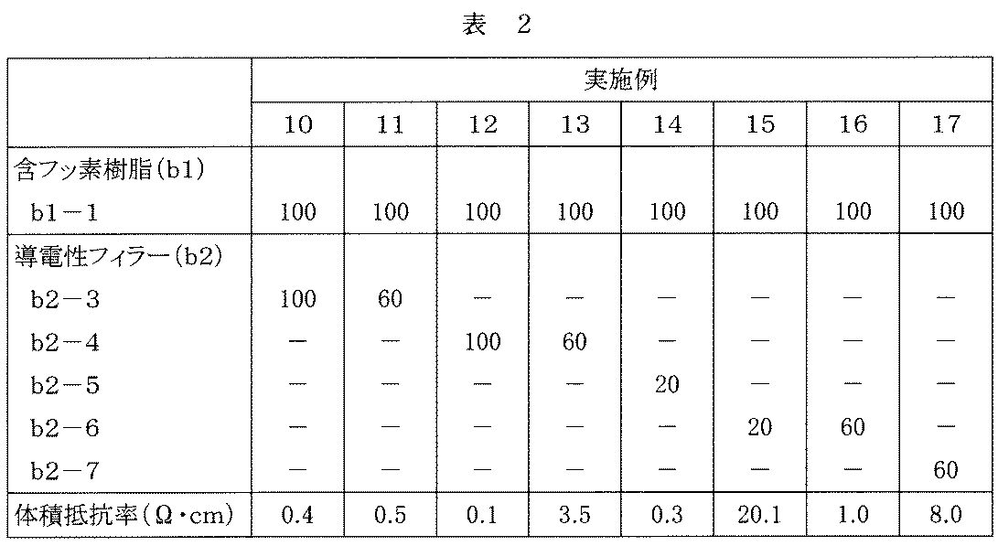
- Example 1 A composition having the following composition was prepared with a planetary mill and coated on an aluminum foil (thickness: 15 ⁇ m) with a bar coater to form a conductive protective layer (thickness: 5.8 ⁇ m) on the aluminum foil. A laminate was obtained.
- B1-1 Fluorine-containing resin: Composition: PVdF Weight average molecular weight (Mw): 110,000 (b2-1) conductive filler: Type: Conductive graphite (Artificial graphite HAG manufactured by Nippon Graphite Co., Ltd.) Average particle size: 5 ⁇ m Volume resistivity: 0.05 ⁇ ⁇ cm (B4-1) Organic solvent: NMP (N-methylpyrrolidone)
- Example 2 In Example 1, except that the blending amount of the conductive filler was changed to 150 parts by mass, a coating material was prepared in the same manner as in Example 1, and a conductive protective layer (thickness: 6 ⁇ m) was formed on the aluminum foil. A laminate was obtained.
- the conductivity level (0.09 ⁇ ⁇ cm) obtained in this example is a region called a highly conductive material and can be compatible with good workability.
- a voltage is applied to this laminate, heat generation is observed, so that it can be used as a heater or an electrode.
- Example 3 A coating material was prepared in the same manner as in Example 1 except that the following fluororesin (b1-2) was used as the fluororesin (b1) in Example 1, and a conductive protective layer (thickness: 6 m) was formed.
- Example 4 In Example 3, except that the blending amount of the conductive filler was changed to 150 parts by mass, a coating material was prepared in the same manner as in Example 3, and a conductive protective layer (thickness: 6 ⁇ m) was formed on the aluminum foil. A laminate was obtained.
- Example 5 A coating material was prepared in the same manner as in Example 1 except that the following conductive filler (b2-2) was used as the conductive filler in Example 1, and a conductive protective layer (thickness: 8 ⁇ m) was formed on the aluminum foil. As a result, a layered product was obtained.
- Conductive filler Type: Conductive carbon fiber (Kureka KCF100 manufactured by Kureha Chemical Industry Co., Ltd.) Average fiber diameter: 10 ⁇ m Volume resistivity: 0.015 ⁇ ⁇ cm
- Example 6 In Example 5, a coating material was prepared in the same manner as in Example 5 except that the blending amount of the conductive filler was changed to 150 parts by mass, and a conductive protective layer (thickness: 8 ⁇ m) was formed on the aluminum foil. A laminate was obtained.
- Example 7 In Example 5, a coating material was prepared in the same manner as in Example 5 except that (b1-2) used in Example 3 was used as the fluororesin (b1), and a conductive protective layer (thickness) was formed on the aluminum foil. S: 8 ⁇ m) was obtained.
- Example 8 In Example 1, 50 parts by mass of the conductive graphite (b2-1) used in Example 1 and 50 parts by mass of the conductive carbon fiber (b2-2) used in Example 5 were used in combination as the conductive filler. A paint was prepared in the same manner as in Example 1 to obtain a laminate in which a conductive protective layer (thickness 8 ⁇ m) was formed on an aluminum foil.
- Example 9 In Example 1, except that the blending amount of the conductive filler was changed to 60 parts by mass, a paint was prepared in the same manner as in Example 1, and a conductive protective layer (thickness: 8 ⁇ m) was formed on the aluminum foil. A laminate was obtained.
- Example 5 a paint was prepared in the same manner as in Example 5 except that the same amount of MT carbon (Thermax N990 manufactured by Cancarb) was used instead of the conductive filler, and a conductive protective layer (thickness) was formed on the aluminum foil. : 5 ⁇ m) was obtained.
- MT carbon Thermax N990 manufactured by Cancarb
- Example 7 a paint was prepared in the same manner as in Example 7 except that the same amount of MT carbon (Thermax N990 manufactured by Cancarb) was used instead of the conductive filler, and a conductive protective layer (thickness) was formed on the aluminum foil. : 5 ⁇ m) was obtained.
- MT carbon Thermax N990 manufactured by Cancarb
- Example 10 In Example 5, a paint was prepared in the same manner as in Example 5 except that the following conductive filler (b2-3) was used as the conductive filler, and a conductive protective layer (thickness: 5 ⁇ m) was formed on the aluminum foil. As a result, a layered product was obtained.
- Conductive filler Type: Conductive graphite (Earth graphite HOP manufactured by Nippon Graphite Co., Ltd.) Average particle size: 4 ⁇ m Volume resistivity: 0.002 ⁇ ⁇ cm
- Example 11 In Example 10, except that the blending amount of the conductive filler was changed to 60 parts by mass, a coating material was prepared in the same manner as in Example 10, and a conductive protective layer (thickness: 5 ⁇ m) was formed on the aluminum foil. A laminate was obtained.
- Example 12 In Example 5, a coating material was prepared in the same manner as in Example 5 except that the following conductive filler (b2-4) was used as the conductive filler, and a conductive protective layer (thickness: 1.. 4 ⁇ m) was obtained.
- Conductive filler Type: Conductive graphite (scale graphite JB-5 manufactured by Nippon Graphite Co., Ltd.) Average particle size: 8 ⁇ m Volume resistivity: 0.0003 ⁇ ⁇ cm
- Example 13 In Example 12, except that the blending amount of the conductive filler was changed to 60 parts by mass, a paint was prepared in the same manner as in Example 12, and a conductive protective layer (thickness: 4 ⁇ m) was formed on the aluminum foil. A laminate was obtained.
- Example 14 In Example 5, the following conductive filler (b2-5) was used as the conductive filler, and the paint was prepared in the same manner as in Example 5 except that the blending amount was changed to 20 parts by mass. A laminate having a conductive protective layer (thickness: 2.8 ⁇ m) was obtained.
- Example 15 In Example 5, the following conductive filler (b2-6) was used as the conductive filler, and the paint was prepared in the same manner as in Example 5 except that the blending amount was changed to 20 parts by mass. A laminate having a conductive protective layer (thickness: 1.4 ⁇ m) was obtained.
- Example 16 In Example 15, except that the blending amount of the conductive filler was changed to 60 parts by mass, a coating material was prepared in the same manner as in Example 15, and a conductive protective layer (thickness: 2.0 ⁇ m) was formed on the aluminum foil. A laminated body was obtained.
- Example 17 In Example 5, the following conductive filler (b2-7) was used as the conductive filler, and the coating amount was prepared in the same manner as in Example 5 except that the blending amount was changed to 60 parts by mass. A laminate having a conductive protective layer (thickness: 0.3 ⁇ m) was obtained.
- Conductive filler Type: Conductive nanoporous carbon (Nanoporous carbon manufactured by Easy-N) Average particle size: 35 nm Volume resistivity: 0.1 ⁇ ⁇ cm
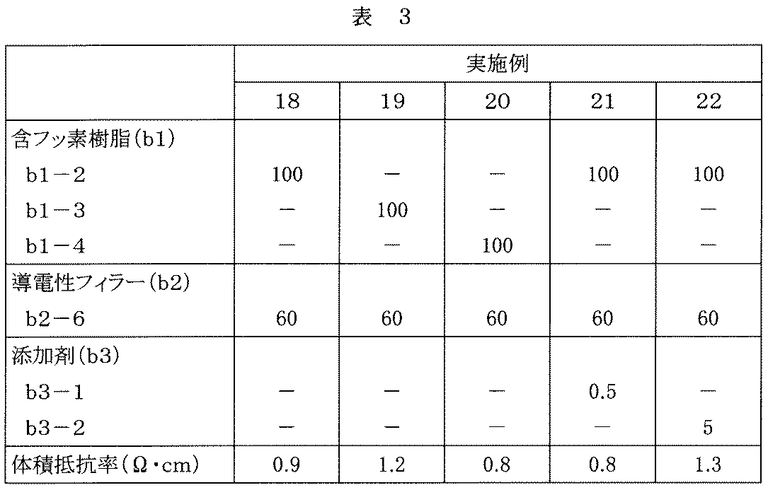
- Example 18 A coating material was prepared in the same manner as in Example 16 except that the fluororesin was changed to fluororesin (b1-2), and a laminate having a conductive protective layer (thickness: 2.0 ⁇ m) formed on an aluminum foil was prepared. Obtained.
- Example 19 A coating material was prepared in the same manner as in Example 16 except that the fluororesin was changed to the next fluororesin (b1-3), and a conductive protective layer (thickness: 2.3 ⁇ m) formed on an aluminum foil Got the body.
- Example 20 A coating material was prepared in the same manner as in Example 16 except that the fluororesin was changed to the next fluororesin (b1-4), and a conductive protective layer (thickness: 2.7 ⁇ m) was formed on the aluminum foil. Got the body.
- Example 21 A paint was prepared in the same manner as in Example 18 except that 0.5 part by mass of tetraethoxysilane (b3-1) was added as an additive (b3), and a conductive protective layer (thickness: 2. 1 m) was formed.
- Example 22 A paint was prepared in the same manner as in Example 18 except that 5 parts by mass of the acrylic rubber fine particles (b3-2) were added as an additive (b3), and a conductive protective layer (thickness: 2.1 ⁇ m) was formed on the aluminum foil. As a result, a layered product was obtained.
- Example 23 A coating material was prepared in the same manner as in Example 16 except that the fluororesin was changed to the next fluororesin (b1-5), and a conductive protective layer (thickness: 2.7 ⁇ m) was formed on the aluminum foil. Got the body.
- the volume resistivity of the obtained laminate was examined.
- the volume resistivity was 1.0 ⁇ ⁇ cm.
- Example 24 A coating material was prepared in the same manner as in Example 16 except that the fluororesin was changed to the next fluororesin (b1-6), and a conductive protective layer (thickness: 2.7 ⁇ m) was formed on the aluminum foil. Got the body.
- the volume resistivity of the obtained laminate was examined.
- the volume resistivity was 0.9 ⁇ ⁇ cm.
- Example 25 (Production of laminate cell) A positive electrode active material obtained by mixing LiNi 0.33 Co 0.33 Al 0.33 O 2 , carbon black, and polyvinylidene fluoride (manufactured by Kureha Chemical Co., Ltd., trade name: KF-1000) at 90/3/7 (mass% ratio) is N-methyl.
- a laminate positive electrode current collector in which a conductive protective layer is formed on the aluminum foil (thickness 15 ⁇ m) produced in Example 1 from the composition for forming a positive electrode mixture layer dispersed in -2-pyrrolidone into a slurry. And then drying to form a positive electrode mixture layer on the conductive protective layer, and then compression-molding with a roller press machine, cutting, welding the lead body, and strip-shaped positive electrode Was made.
- styrene-butadiene rubber dispersed in distilled water is added to artificial graphite powder (manufactured by Hitachi Chemical Co., Ltd., trade name: MAG-D) to a solid content of 6% by mass and mixed with a disperser.
- a disperser After applying the slurry in a uniform manner on a negative electrode current collector (copper foil having a thickness of 10 ⁇ m), drying, forming a negative electrode mixture layer, and then compression molding with a roller press machine and cutting, It dried and welded the lead body and produced the strip
- the belt-like positive electrode 1 is cut into 40 mm ⁇ 72 mm (with a 10 mm ⁇ 10 mm positive electrode terminal 4), and the belt-like negative electrode 2 is cut into 42 mm ⁇ 74 mm (10 mm ⁇ 10 mm negative electrode).
- the lead body was cut to each terminal 5 and a lead body was welded to each terminal.
- a microporous polyethylene film having a thickness of 20 ⁇ m is cut into a size of 78 mm ⁇ 46 mm to form a separator 3, and a positive electrode and a negative electrode are set so as to sandwich the separator 3, and an aluminum laminate packaging material as shown in FIG.
- an electrolytic solution a solution obtained by dissolving LiPF 6 in a mixed solvent of ethylene carbonate (EC) and ethyl methyl carbonate (EMC) at a concentration of 1 mol / liter was used.
- EC ethylene carbonate
- EMC ethyl methyl carbonate
- Cycle characteristics 1 were examined in the following manner using the produced laminate cell.
- Example 26 In Example 25, the cycle characteristic 2 was examined by changing the measurement conditions of the cycle characteristic 1 as follows.
- the cycle characteristic 2 was as good as 84%.
- the cycle characteristic 2 was 72%.
- Example 27 A laminate cell was prepared in the same manner as in Example 25 except that the electrolyte used was EC / EMC / HCF 2 CF 2 CH 2 OCF 2 CF 2 H (20/60/20: volume ratio), and cycle characteristics were obtained. 2 was examined.
- the cycle characteristic 2 was as high as 95%.
- the cycle characteristic 2 was 88%.
- Example 28 The positive electrode current collector provided with the conductive protective layer prepared in Examples 1 to 24 on an aluminum foil was used as a working electrode, lithium as a counter electrode and a reference electrode, and the working electrode having a size of 0.5 ⁇ 0.7 cm. It cut
- EC ethylene carbonate
- MEC methyl ethyl carbonate
- a BAS voltammetric closed cell (VC-4) place the CV electrode prepared above on the working electrode, use Li for the counter electrode and reference electrode, and put 3 ml of the above electrolyte into the measuring cell. Produced.
- This measurement cell was scanned at 5 mV / sec from 3 V to 10 V at 25 ° C. (constant) using a potentio-galvanostat (Solartron 1287 type), and the current change was measured to be 0.5 mA / cm 2. The voltage was measured.
- Evaluation was made based on whether or not the measured voltage was 5.5 V or more because the limit value of the withstand voltage of the electrolyte was about 5.5 V.
- the measurement voltage was 5.5 V or higher for the electrodes of any of the examples.
- the limit voltage at the time of using the electrical power collector which consists only of aluminum foil as a working electrode was 4.5V.
Landscapes
- Chemical & Material Sciences (AREA)
- Engineering & Computer Science (AREA)
- Chemical Kinetics & Catalysis (AREA)
- Electrochemistry (AREA)
- General Chemical & Material Sciences (AREA)
- Materials Engineering (AREA)
- Composite Materials (AREA)
- Manufacturing & Machinery (AREA)
- Cell Electrode Carriers And Collectors (AREA)
- Secondary Cells (AREA)
- Battery Electrode And Active Subsutance (AREA)
Abstract
Description
正極集電体を構成する材料としては、たとえばアルミニウムやその合金、ステンレス鋼、ニッケルやその合金、チタンやその合金、アルミニウムまたはステンレス鋼の表面にカーボンまたはチタンを処理させたものなどが用いられる。これらの中でも、アルミニウムおよびアルミニウム合金が特に保護される正極集電体としてあげられる。これらの材料は表面を酸化して用いることもできる。また、表面処理により集電体表面に凹凸を付けることにより接着性が上がるため好ましい。正極集電体の厚さは、通常5~30μmの範囲である。
本発明の正極集電積層体には、集電体(A)上にフッ素樹脂(b1)と導電性フィラー(b2)を含む導電性保護層(B)が設けられている。
フッ素樹脂(b1)としては、酸化に弱くなければ特に制限なく使用でき、たとえばフッ化ビニリデン(VdF)由来の構造単位を含むフッ素樹脂(VdF系樹脂)、側鎖にフッ素原子を含むアクリレート/メタクリレート、テトラフルオロエチレン(TFE)と炭化水素系ビニルエーテル/ビニルエステルとの共重合体などがあげられる。なかでも、導電性フィラーを含有させることが容易であること、また、耐酸化性に優れ、柔軟性も保持しやすいことから、VdF系樹脂が好ましい。
本発明に用いる導電性フィラー(b2)とは、体積抵抗率が1×10⁻⁹~1Ω・cmのフィラーをいう。好ましい体積抵抗率は1×10⁻⁸~1×10⁻¹Ω・cmである。
フッ素樹脂(b1)および導電性フィラー(b2)に加えて、要すれば他の成分を適宜配合してもよい。
体積抵抗率をつぎの方法にて測定する。なお、体積抵抗率は積層体について測定しているが、集電体の体積抵抗率は導電性保護層の体積抵抗率に比べて無視できる程度であるので、積層体の体積抵抗率の値を導電性保護層の体積抵抗率とみなす。
厚さ2.2mm、幅26mm、長さ60mmのサンプルを作製し、JIS K7194に対応し、体積抵抗率を測定する。測定装置は、三菱化学(株)製LorestaMP(製品名MCP-T350)で、四探針法によって体積抵抗率の測定を行う。
(株)ミツトヨ製のクイックマクロMDQ-30Mを用いて測定する。
つぎの組成の組成物を遊星ミルにて調製し、バーコーターでアルミニウム箔(厚さ15μm)上に塗工し、アルミニウム箔上に導電性保護層(厚さ:5.8μm)が形成された積層体を得た。
(b2)導電性フィラー 100質量部
(b4)有機溶剤 800質量部
(b1-1)含フッ素樹脂:
組成:PVdF
重量平均分子量(Mw):11万
(b2-1)導電性フィラー:
種類:導電性グラファイト(日本黒鉛(株)製の人造黒鉛HAG)
平均粒子径:5μm
体積抵抗率:0.05Ω・cm
(b4-1)有機溶剤:NMP(N-メチルピロリドン)
実施例1において、導電性フィラーの配合量を150質量部に変更したほかは実施例1と同様にして塗料を調製し、アルミニウム箔上に導電性保護層(厚さ:6μm)が形成された積層体を得た。
実施例1において、含フッ素樹脂(b1)としてつぎのフッ素樹脂(b1-2)を使用したほかは実施例1と同様にして塗料を調製し、アルミニウム箔上に導電性保護層(厚さ:6μm)が形成された積層体を得た。
組成:TFE/VdF/HFP=37/60.5/2.5(モル比)
重量平均分子量(Mw):17万
実施例3において、導電性フィラーの配合量を150質量部に変更したほかは実施例3と同様にして塗料を調製し、アルミニウム箔上に導電性保護層(厚さ:6μm)が形成された積層体を得た。
実施例1において、導電性フィラーとしてつぎの導電性フィラー(b2-2)を使用したほかは実施例1と同様にして塗料を調製し、アルミニウム箔上に導電性保護層(厚さ:8μm)が形成された積層体を得た。
種類:導電性カーボンファイバー(呉羽化学工業(株)製のクレカKCF100)
平均繊維径:10μm
体積抵抗率:0.015Ω・cm
実施例5において、導電性フィラーの配合量を150質量部に変更したほかは実施例5と同様にして塗料を調製し、アルミニウム箔上に導電性保護層(厚さ:8μm)が形成された積層体を得た。
実施例5において、含フッ素樹脂(b1)として実施例3で用いた(b1-2)を使用したほかは実施例5と同様にして塗料を調製し、アルミニウム箔上に導電性保護層(厚さ:8μm)が形成された積層体を得た。
実施例1において、導電性フィラーとして実施例1で用いた導電性グラファイト(b2-1)50質量部と実施例5で用いた導電性カーボンファイバー(b2-2)50質量部を併用したほかは実施例1と同様にして塗料を調製し、アルミニウム箔上に導電性保護層(厚さ8μm)が形成された積層体を得た。
実施例1において、導電性フィラーの配合量を60質量部に変更したほかは実施例1と同様にして塗料を調製し、アルミニウム箔上に導電性保護層(厚さ:8μm)が形成された積層体を得た。
実施例5において、導電性フィラーに代えて同量のMTカーボン(Cancarb社製ThermaxN990)を使用したほかは実施例5と同様にして塗料を調製し、アルミニウム箔上に導電性保護層(厚さ:5μm)が形成された積層体を得た。
実施例7において、導電性フィラーに代えて同量のMTカーボン(Cancarb社製ThermaxN990)を使用したほかは実施例7と同様にして塗料を調製し、アルミニウム箔上に導電性保護層(厚さ:5μm)が形成された積層体を得た。

実施例5において、導電性フィラーとしてつぎの導電性フィラー(b2-3)を使用したほかは実施例5と同様にして塗料を調製し、アルミニウム箔上に導電性保護層(厚さ:5μm)が形成された積層体を得た。
種類:導電性グラファイト(日本黒鉛(株)製の土状黒鉛HOP)
平均粒子径:4μm
体積抵抗率:0.002Ω・cm
実施例10において、導電性フィラーの配合量を60質量部に変更したほかは実施例10と同様にして塗料を調製し、アルミニウム箔上に導電性保護層(厚さ:5μm)が形成された積層体を得た。
実施例5において、導電性フィラーとしてつぎの導電性フィラー(b2-4)を使用したほかは実施例5と同様にして塗料を調製し、アルミニウム箔上に導電性保護層(厚さ:1.4μm)が形成された積層体を得た。
種類:導電性グラファイト(日本黒鉛(株)製の鱗状黒鉛JB-5)
平均粒子径:8μm
体積抵抗率:0.0003Ω・cm
実施例12において、導電性フィラーの配合量を60質量部に変更したほかは実施例12と同様にして塗料を調製し、アルミニウム箔上に導電性保護層(厚さ:4μm)が形成された積層体を得た。
実施例5において、導電性フィラーとしてつぎの導電性フィラー(b2-5)を使用し、配合量を20質量部に変更したほかは実施例5と同様にして塗料を調製し、アルミニウム箔上に導電性保護層(厚さ:2.8μm)が形成された積層体を得た。
種類:ケッチェンブラック(ライオン(株)製のECP-600JD)
平均粒子径:40nm
体積抵抗率:0.1Ω・cm
実施例5において、導電性フィラーとしてつぎの導電性フィラー(b2-6)を使用し、配合量を20質量部に変更したほかは実施例5と同様にして塗料を調製し、アルミニウム箔上に導電性保護層(厚さ:1.4μm)が形成された積層体を得た。
種類:アセチレンブラック(電気化学工業(株)製のデンカブラック)
平均粒子径:35nm
体積抵抗率:0.2Ω・cm
実施例15において、導電性フィラーの配合量を60質量部に変更したほかは実施例15と同様にして塗料を調製し、アルミニウム箔上に導電性保護層(厚さ:2.0μm)が形成された積層体を得た。
実施例5において、導電性フィラーとしてつぎの導電性フィラー(b2-7)を使用し、配合量を60質量部に変更したほかは実施例5と同様にして塗料を調製し、アルミニウム箔上に導電性保護層(厚さ:0.3μm)が形成された積層体を得た。
種類:導電性ナノポーラスカーボン(Easy-N社製ナノポーラスカーボン)
平均粒子径:35nm
体積抵抗率:0.1Ω・cm
フッ素樹脂をフッ素樹脂(b1-2)に変更したほかは実施例16と同様にして塗料を調製し、アルミニウム箔上に導電性保護層(厚さ:2.0μm)が形成された積層体を得た。
フッ素樹脂をつぎのフッ素樹脂(b1-3)に変更したほかは実施例16と同様にして塗料を調製し、アルミニウム箔上に導電性保護層(厚さ:2.3μm)が形成された積層体を得た。
組成:VdF/TFE=80/20(モル比)
重量平均分子量(Mw):17万
フッ素樹脂をつぎのフッ素樹脂(b1-4)に変更したほかは実施例16と同様にして塗料を調製し、アルミニウム箔上に導電性保護層(厚さ:2.7μm)が形成された積層体を得た。
組成:VdF/TFE=88/12(モル比)
重量平均分子量(Mw):15万
添加剤(b3)としてテトラエトキシシラン(b3-1)を0.5質量部配合したほかは実施例18と同様にして塗料を調製し、アルミニウム箔上に導電性保護層(厚さ:2.1μm)が形成された積層体を得た。
添加剤(b3)としてアクリルゴム微粒子(b3-2)を5質量部配合したほかは実施例18と同様にして塗料を調製し、アルミニウム箔上に導電性保護層(厚さ:2.1μm)が形成された積層体を得た。
フッ素樹脂をつぎのフッ素樹脂(b1-5)に変更したほかは実施例16と同様にして塗料を調製し、アルミニウム箔上に導電性保護層(厚さ:2.7μm)が形成された積層体を得た。
組成:VdF/TFE=67/33(モル比)
重量平均分子量(Mw):20万
フッ素樹脂をつぎのフッ素樹脂(b1-6)に変更したほかは実施例16と同様にして塗料を調製し、アルミニウム箔上に導電性保護層(厚さ:2.7μm)が形成された積層体を得た。
組成:VdF/HFP=92/8(モル比)
重量平均分子量(Mw):20万
(ラミネートセルの作製)
LiNi0.33Co0.33Al0.33O2とカーボンブラックとポリフッ化ビニリデン(呉羽化学(株)製。商品名KF-1000)を90/3/7(質量%比)で混合した正極活物質をN-メチル-2-ピロリドンに分散してスラリー状とした正極合剤層形成用組成物を実施例1で作製したアルミニウム箔(厚さ15μm)上に導電性保護層が形成された積層体(正極集電体)上に均一に塗布し、乾燥して正極合剤層を導電性保護層上に形成し、その後、ローラプレス機により圧縮成形した後、切断し、リード体を溶接して、帯状の正極を作製した。
充電放電は、1.0Cで4.3Vにて充電電流が1/10Cになるまで充電し0.2C相当の電流で3.0Vまで放電し、引き続き、1.0Cで4.3Vにて充電電流が1/10Cになるまで充電するサイクルを1サイクルとし、5サイクル目と比較した50サイクル目の容量保持率(%)をサイクル特性1とする。
実施例25において、サイクル特性1の測定条件をつぎのように変更して、サイクル特性2を調べた。
充電放電は、1.0Cで4.4Vにて充電電流が1/10Cになるまで充電し0.2C相当の電流で3.0Vまで放電し、引き続き、1.0Cで4.3Vにて充電電流が1/10Cになるまで充電するサイクルを1サイクルとし、5サイクル目と比較した50サイクル目の容量保持率(%)をサイクル特性2とする。
実施例25において、使用する電解液をEC/EMC/HCF2CF2CH2OCF2CF2H(20/60/20:体積比)としたほかは同様にしてラミネートセルを作製し、サイクル特性2を調べた。
実施例1~24で作製した導電性保護層をアルミニウム箔上に設けた正極集電体を作用極に、リチウムを対極、参照極とし、作用極を0.5×0.7cmの大きさに切断し、ニッケル線を抵抗溶接で溶接してCV用の電極を作製した。測定用の電解液としては、エチレンカーボネート(EC)/メチルエチルカーボネート(MEC)(=30/70体積%)の電解質塩溶解用溶媒に電解質塩としてLiPF6を1.0モル/リットルの濃度となるように加えた電解液を使用した。
2 負極
3 セパレータ
4 正極端子
5 負極端子
6 アルミニウムラミネート包装材
Claims (10)
- 正極集電体(A)上に、フッ素樹脂(b1)と導電性フィラー(b2)を含む導電性保護層(B)が設けられてなる正極集電積層体。
- 前記フッ素樹脂(b1)が、フッ化ビニリデンに由来する構造単位を含むフッ素樹脂である請求項1記載の正極集電積層体。
- 前記フッ素樹脂(b1)が、ポリフッ化ビニリデン、テトラフルオロエチレン/フッ化ビニリデン共重合体樹脂、テトラフルオロエチレン/フッ化ビニリデン/ヘキサフルオロプロピレン共重合体樹脂、および/またはフッ化ビニリデン/ヘキサフルオロプロピレン共重合体樹脂である請求項1記載の正極集電積層体。
- 前記導電性フィラー(b2)が、粒子状フィラー、繊維状フィラー、またはこれらの組合せである請求項1~3のいずれかに記載の正極集電積層体。
- 前記導電性フィラー(b2)が、導電性カーボンフィラーである請求項1~4のいずれかに記載の正極集電積層体。
- 前記導電性保護層(B)の体積抵抗率が0.001~50Ω・cmである請求項1~5のいずれかに記載の正極集電積層体。
- 前記フッ素樹脂(b1)100質量部に対して導電性フィラー(b2)が5~300質量部含まれている請求項1~6のいずれかに記載の正極集電積層体。
- 前記導電性保護層(B)が、フッ素樹脂(b1)と導電性フィラー(b2)を含むフッ素樹脂塗料組成物を塗布して形成されてなる請求項1~7のいずれかに記載の正極集電積層体。
- 請求項1~8のいずれかに記載の集電積層体の導電性保護層(B)上に、正極合剤層(C)が設けられてなる正極積層体。
- 正極、負極および非水電解液を備え、正極が請求項9記載の正極積層体であるリチウム二次電池。
Priority Applications (3)
| Application Number | Priority Date | Filing Date | Title |
|---|---|---|---|
| US13/497,900 US20120237824A1 (en) | 2009-09-25 | 2010-09-22 | Positive electrode current collector laminate for lithium secondary battery |
| CN2010800423010A CN102648546A (zh) | 2009-09-25 | 2010-09-22 | 锂二次电池的正极集电层积体 |
| JP2011533000A JPWO2011037124A1 (ja) | 2009-09-25 | 2010-09-22 | リチウム二次電池の正極集電積層体 |
Applications Claiming Priority (2)
| Application Number | Priority Date | Filing Date | Title |
|---|---|---|---|
| JP2009221336 | 2009-09-25 | ||
| JP2009-221336 | 2009-09-25 |
Publications (1)
| Publication Number | Publication Date |
|---|---|
| WO2011037124A1 true WO2011037124A1 (ja) | 2011-03-31 |
Family
ID=43795871
Family Applications (1)
| Application Number | Title | Priority Date | Filing Date |
|---|---|---|---|
| PCT/JP2010/066370 Ceased WO2011037124A1 (ja) | 2009-09-25 | 2010-09-22 | リチウム二次電池の正極集電積層体 |
Country Status (5)
| Country | Link |
|---|---|
| US (1) | US20120237824A1 (ja) |
| JP (1) | JPWO2011037124A1 (ja) |
| KR (1) | KR20120047301A (ja) |
| CN (1) | CN102648546A (ja) |
| WO (1) | WO2011037124A1 (ja) |
Cited By (14)
| Publication number | Priority date | Publication date | Assignee | Title |
|---|---|---|---|---|
| JP2013041704A (ja) * | 2011-08-12 | 2013-02-28 | Mitsubishi Materials Corp | 非水電解質二次電池用電極、およびその製造方法 |
| WO2013151046A1 (ja) * | 2012-04-04 | 2013-10-10 | 古河スカイ株式会社 | 集電体、電極構造体、非水電解質電池及び蓄電部品 |
| WO2014046112A1 (ja) * | 2012-09-21 | 2014-03-27 | 古河スカイ株式会社 | 集電体、電極構造体及び蓄電部品 |
| CN104205426A (zh) * | 2012-04-18 | 2014-12-10 | 株式会社Lg化学 | 电极和包含所述电极的二次电池 |
| EP2716448A4 (en) * | 2011-05-23 | 2015-03-04 | Kaneka Corp | MULTILAYER CONDUCTIVE FILM, RETRACTOR THEREOF, BATTERY AND BIPOLAR BATTERY |
| CN104428929A (zh) * | 2012-07-13 | 2015-03-18 | 古河电气工业株式会社 | 集电体、电极结构体、非水电解质电池或蓄电部件 |
| EP2738856A4 (en) * | 2011-07-29 | 2015-07-01 | Uacj Corp | COLLECTOR, ELECTRODE STRUCTURE, NON-WATER ELECTROLYTE BATTERY AND ELECTRICITY MEMORY COMPONENT |
| JPWO2015156062A1 (ja) * | 2014-04-11 | 2017-04-13 | Necエナジーデバイス株式会社 | 二次電池 |
| WO2017199798A1 (ja) * | 2016-05-16 | 2017-11-23 | Jsr株式会社 | 蓄電デバイス用集電体およびその製造方法、蓄電デバイス用電極およびその製造方法、保護層形成用スラリー、ならびに蓄電デバイス |
| WO2019017054A1 (ja) * | 2017-07-21 | 2019-01-24 | パナソニックIpマネジメント株式会社 | 二次電池用正極、及び二次電池 |
| JP2019075300A (ja) * | 2017-10-17 | 2019-05-16 | 三洋化成工業株式会社 | 樹脂集電体、積層集電体、及び、リチウムイオン電池 |
| JP2019129009A (ja) * | 2018-01-22 | 2019-08-01 | トヨタ自動車株式会社 | 非水電解質二次電池 |
| JPWO2018147390A1 (ja) * | 2017-02-10 | 2019-12-12 | 三井化学株式会社 | 集電体、電極及び非水電解質二次電池 |
| JP2021532542A (ja) * | 2018-08-08 | 2021-11-25 | エルジー・ケム・リミテッド | リチウム二次電池用電極及びそれを含むリチウム二次電池 |
Families Citing this family (25)
| Publication number | Priority date | Publication date | Assignee | Title |
|---|---|---|---|---|
| US20140085773A1 (en) * | 2012-09-25 | 2014-03-27 | Yunasko Limited | Hybrid electrochemical energy storage device |
| JP6011634B2 (ja) * | 2012-11-12 | 2016-10-19 | 株式会社豊田自動織機 | 非水電解質二次電池 |
| KR20140090902A (ko) * | 2013-01-10 | 2014-07-18 | 삼성에스디아이 주식회사 | 이차 전지 및 이차 전지 모듈 |
| JP6371861B2 (ja) | 2014-01-27 | 2018-08-08 | ユッチンソン | 電気エネルギー貯蔵システムのための、保護導電層を含むコレクタを有する電極および対応する製造方法 |
| FR3028088B1 (fr) * | 2014-11-03 | 2016-12-23 | Hutchinson | Electrodes conductrices et leur procede de fabrication |
| JP6777388B2 (ja) * | 2015-02-27 | 2020-10-28 | パナソニック株式会社 | 非水電解質二次電池 |
| NZ720939A (en) * | 2016-03-02 | 2017-12-22 | Resene Paints Ltd | Touch sensitive control system for non-electronic display substrate surfaces |
| CN106009979A (zh) * | 2016-07-07 | 2016-10-12 | 无锡市宝来电池有限公司 | 一种环保型的电池导电涂层材料 |
| CN107170507B (zh) * | 2017-04-13 | 2019-05-03 | 湖南文理学院 | 一种复合导电薄膜及其制备方法 |
| CN109755462B (zh) * | 2017-11-08 | 2021-01-12 | 宁德时代新能源科技股份有限公司 | 一种正极极片、电化学装置及安全涂层 |
| JP6998278B2 (ja) * | 2018-06-13 | 2022-02-10 | 三洋化成工業株式会社 | 樹脂集電体、積層型樹脂集電体、及び、リチウムイオン電池 |
| CN111200111B (zh) * | 2018-11-16 | 2021-03-23 | 宁德时代新能源科技股份有限公司 | 一种正极极片及电化学装置 |
| CN111200110A (zh) | 2018-11-16 | 2020-05-26 | 宁德时代新能源科技股份有限公司 | 一种正极极片及电化学装置 |
| CN110676460B (zh) | 2018-12-29 | 2022-01-18 | 宁德时代新能源科技股份有限公司 | 一种电极极片和电化学装置 |
| CN110661002B (zh) | 2018-12-29 | 2021-06-29 | 宁德时代新能源科技股份有限公司 | 一种电极极片和电化学装置 |
| CN110660963B (zh) | 2018-12-29 | 2021-04-27 | 宁德时代新能源科技股份有限公司 | 一种电极极片和电化学装置 |
| CN110660957B (zh) | 2018-12-29 | 2020-12-04 | 宁德时代新能源科技股份有限公司 | 一种电极极片和电化学装置 |
| CN110943201B (zh) | 2019-04-15 | 2021-02-26 | 宁德时代新能源科技股份有限公司 | 一种正极极片和电化学装置 |
| CN110943200B (zh) | 2019-04-15 | 2021-03-09 | 宁德时代新能源科技股份有限公司 | 一种电极极片和电化学装置 |
| CN110943222B (zh) | 2019-04-15 | 2021-01-12 | 宁德时代新能源科技股份有限公司 | 一种电极极片和电化学装置 |
| CN111180665A (zh) | 2019-06-28 | 2020-05-19 | 宁德时代新能源科技股份有限公司 | 一种电极极片和电化学装置 |
| CN112186195B (zh) * | 2019-07-01 | 2023-11-03 | 宁德时代新能源科技股份有限公司 | 一种正极极片和电化学装置 |
| CN110707364B (zh) * | 2019-09-10 | 2021-01-01 | 深圳先进技术研究院 | 二次电池的制备方法 |
| WO2021187965A1 (ko) * | 2020-03-19 | 2021-09-23 | 주식회사 엘지에너지솔루션 | 전도성의 부식 방지층이 탭 상에 형성되어 있는 양극 집전체, 이를 포함하는 양극, 및 리튬 이차전지 |
| FR3108794B1 (fr) | 2020-03-26 | 2025-02-28 | Accumulateurs Fixes | Collecteur de courant amélioré pour batterie |
Citations (5)
| Publication number | Priority date | Publication date | Assignee | Title |
|---|---|---|---|---|
| JPH07201362A (ja) * | 1993-12-29 | 1995-08-04 | Tdk Corp | リチウム二次電池 |
| JPH11339771A (ja) * | 1998-05-22 | 1999-12-10 | Fuji Photo Film Co Ltd | 非水二次電池 |
| JP2002110249A (ja) * | 2000-09-27 | 2002-04-12 | Matsushita Electric Ind Co Ltd | 非水系二次電池およびその製造方法 |
| JP2009170132A (ja) * | 2008-01-11 | 2009-07-30 | Toyota Motor Corp | 電極およびその製造方法 |
| JP2009252396A (ja) * | 2008-04-02 | 2009-10-29 | Toyota Motor Corp | リチウム二次電池の正極およびその製造方法 |
Family Cites Families (9)
| Publication number | Priority date | Publication date | Assignee | Title |
|---|---|---|---|---|
| DE69409936T2 (de) * | 1993-12-29 | 1998-12-10 | Tdk Corp., Tokio/Tokyo | Lithiumsekundärzelle |
| JPH11228902A (ja) * | 1998-02-17 | 1999-08-24 | Elf Atochem Japan Kk | フッ化ビニリデン系樹脂の金属基材への接着方法、電極構造体、およびその作製方法 |
| CN1354775A (zh) * | 1999-02-18 | 2002-06-19 | 阿托菲纳公司 | 将偏二氟乙烯树脂粘合到金属基材的方法,和电极结构及其生产方法 |
| JP2000243383A (ja) * | 1999-02-22 | 2000-09-08 | Toshiba Battery Co Ltd | リチウム二次電池の製造方法 |
| EP2367224B1 (en) * | 2002-03-25 | 2013-01-09 | Sumitomo Chemical Company, Limited | Method for preparing positive electrode active material for non-aqueous secondary battery |
| TW200519150A (en) * | 2003-12-05 | 2005-06-16 | Showa Denko Kk | Conductive resin composition and molded product thereof |
| JP2005191425A (ja) * | 2003-12-26 | 2005-07-14 | Tdk Corp | キャパシタ用電極の製造方法 |
| JP2006324288A (ja) * | 2005-05-17 | 2006-11-30 | Tdk Corp | 電気化学キャパシタ用電極の製造方法 |
| WO2012036288A1 (ja) * | 2010-09-17 | 2012-03-22 | ダイキン工業株式会社 | 非水二次電池などの集電積層体の導電性保護層形成用ペースト |
-
2010
- 2010-09-22 JP JP2011533000A patent/JPWO2011037124A1/ja active Pending
- 2010-09-22 US US13/497,900 patent/US20120237824A1/en not_active Abandoned
- 2010-09-22 WO PCT/JP2010/066370 patent/WO2011037124A1/ja not_active Ceased
- 2010-09-22 CN CN2010800423010A patent/CN102648546A/zh active Pending
- 2010-09-22 KR KR1020127007718A patent/KR20120047301A/ko not_active Withdrawn
Patent Citations (5)
| Publication number | Priority date | Publication date | Assignee | Title |
|---|---|---|---|---|
| JPH07201362A (ja) * | 1993-12-29 | 1995-08-04 | Tdk Corp | リチウム二次電池 |
| JPH11339771A (ja) * | 1998-05-22 | 1999-12-10 | Fuji Photo Film Co Ltd | 非水二次電池 |
| JP2002110249A (ja) * | 2000-09-27 | 2002-04-12 | Matsushita Electric Ind Co Ltd | 非水系二次電池およびその製造方法 |
| JP2009170132A (ja) * | 2008-01-11 | 2009-07-30 | Toyota Motor Corp | 電極およびその製造方法 |
| JP2009252396A (ja) * | 2008-04-02 | 2009-10-29 | Toyota Motor Corp | リチウム二次電池の正極およびその製造方法 |
Cited By (25)
| Publication number | Priority date | Publication date | Assignee | Title |
|---|---|---|---|---|
| EP2716448A4 (en) * | 2011-05-23 | 2015-03-04 | Kaneka Corp | MULTILAYER CONDUCTIVE FILM, RETRACTOR THEREOF, BATTERY AND BIPOLAR BATTERY |
| EP2738856A4 (en) * | 2011-07-29 | 2015-07-01 | Uacj Corp | COLLECTOR, ELECTRODE STRUCTURE, NON-WATER ELECTROLYTE BATTERY AND ELECTRICITY MEMORY COMPONENT |
| JP2013041704A (ja) * | 2011-08-12 | 2013-02-28 | Mitsubishi Materials Corp | 非水電解質二次電池用電極、およびその製造方法 |
| WO2013151046A1 (ja) * | 2012-04-04 | 2013-10-10 | 古河スカイ株式会社 | 集電体、電極構造体、非水電解質電池及び蓄電部品 |
| CN104221195A (zh) * | 2012-04-04 | 2014-12-17 | 株式会社Uacj | 集电体、电极结构体、非水电解质电池及蓄电零部件 |
| CN104205426A (zh) * | 2012-04-18 | 2014-12-10 | 株式会社Lg化学 | 电极和包含所述电极的二次电池 |
| EP2816640A4 (en) * | 2012-04-18 | 2015-08-26 | Lg Chemical Ltd | ELECTRODE AND SECONDARY BATTERY THEREWITH |
| US9786916B2 (en) | 2012-04-18 | 2017-10-10 | Lg Chem, Ltd. | Electrode and secondary battery including the same |
| CN104428929A (zh) * | 2012-07-13 | 2015-03-18 | 古河电气工业株式会社 | 集电体、电极结构体、非水电解质电池或蓄电部件 |
| CN104428929B (zh) * | 2012-07-13 | 2017-10-24 | 古河电气工业株式会社 | 集电体、电极结构体、非水电解质电池或蓄电部件 |
| WO2014046112A1 (ja) * | 2012-09-21 | 2014-03-27 | 古河スカイ株式会社 | 集電体、電極構造体及び蓄電部品 |
| JPWO2015156062A1 (ja) * | 2014-04-11 | 2017-04-13 | Necエナジーデバイス株式会社 | 二次電池 |
| WO2017199798A1 (ja) * | 2016-05-16 | 2017-11-23 | Jsr株式会社 | 蓄電デバイス用集電体およびその製造方法、蓄電デバイス用電極およびその製造方法、保護層形成用スラリー、ならびに蓄電デバイス |
| JPWO2018147390A1 (ja) * | 2017-02-10 | 2019-12-12 | 三井化学株式会社 | 集電体、電極及び非水電解質二次電池 |
| JP7074284B2 (ja) | 2017-02-10 | 2022-05-24 | 三井化学株式会社 | 正極及び非水電解質二次電池 |
| WO2019017054A1 (ja) * | 2017-07-21 | 2019-01-24 | パナソニックIpマネジメント株式会社 | 二次電池用正極、及び二次電池 |
| JPWO2019017054A1 (ja) * | 2017-07-21 | 2020-05-28 | パナソニックIpマネジメント株式会社 | 二次電池用正極、及び二次電池 |
| JP7108842B2 (ja) | 2017-07-21 | 2022-07-29 | パナソニックIpマネジメント株式会社 | 二次電池用正極、及び二次電池 |
| US11437613B2 (en) | 2017-07-21 | 2022-09-06 | Panasonic Intellectual Property Management Co., Ltd. | Secondary battery positive electrode and secondary battery |
| JP2019075300A (ja) * | 2017-10-17 | 2019-05-16 | 三洋化成工業株式会社 | 樹脂集電体、積層集電体、及び、リチウムイオン電池 |
| JP7010653B2 (ja) | 2017-10-17 | 2022-01-26 | 三洋化成工業株式会社 | 樹脂集電体、積層集電体、及び、リチウムイオン電池 |
| JP2019129009A (ja) * | 2018-01-22 | 2019-08-01 | トヨタ自動車株式会社 | 非水電解質二次電池 |
| JP2021532542A (ja) * | 2018-08-08 | 2021-11-25 | エルジー・ケム・リミテッド | リチウム二次電池用電極及びそれを含むリチウム二次電池 |
| JP7110481B2 (ja) | 2018-08-08 | 2022-08-01 | エルジー エナジー ソリューション リミテッド | リチウム二次電池用正極及びそれを含むリチウム二次電池 |
| US12002961B2 (en) | 2018-08-08 | 2024-06-04 | Lg Energy Solution, Ltd. | Electrode for lithium secondary battery and lithium secondary battery comprising same |
Also Published As
| Publication number | Publication date |
|---|---|
| CN102648546A (zh) | 2012-08-22 |
| JPWO2011037124A1 (ja) | 2013-02-21 |
| US20120237824A1 (en) | 2012-09-20 |
| KR20120047301A (ko) | 2012-05-11 |
Similar Documents
| Publication | Publication Date | Title |
|---|---|---|
| JPWO2011037124A1 (ja) | リチウム二次電池の正極集電積層体 | |
| JP5168395B2 (ja) | 非水二次電池などの集電積層体の導電性保護層形成用ペースト | |
| JP5382120B2 (ja) | リチウム二次電池の電極合剤用スラリー、該スラリーを用いた電極およびリチウム二次電池 | |
| JP5609616B2 (ja) | 非水二次電池などの集電積層体の導電性保護層形成用ペースト | |
| CN101320822B (zh) | 非水电解质二次电池及非水电解质二次电池用正极的制造方法 | |
| US20180248220A1 (en) | Nonaqueous electrolyte secondary batteries | |
| JP2010238588A (ja) | リチウム二次電池の集電積層体 | |
| US8105711B2 (en) | Nonaqueous electrolyte secondary battery | |
| JP6044427B2 (ja) | リチウムイオン二次電池正極用集電体、リチウムイオン二次電池用正極及びリチウムイオン二次電池 | |
| US20150147627A1 (en) | Rechargeable lithium battery | |
| CN102077405A (zh) | 用于高电压锂电池的非水电解质 | |
| WO2010131401A1 (ja) | リチウムイオン二次電池用電極及びリチウムイオン二次電池 | |
| CN103904368A (zh) | 锂二次电池 | |
| CN1468455A (zh) | 高性能锂或锂离子电池 | |
| US10096829B2 (en) | Nonaqueous electrolyte secondary batteries | |
| KR20160072009A (ko) | 비수전해질 이차전지용 전극권회 소자, 이를 이용한 비수전해질 이차전지, 및 비수전해질 이차전지용 전극권회 소자의 제조 방법 | |
| WO2015004841A1 (ja) | 非水電解質二次電池 | |
| WO2018168271A1 (ja) | 非水電解質二次電池用正極及び非水電解質二次電池 | |
| US20230069196A1 (en) | Composite, polymer electrolyte, electrochemical device, polymer-based solid-state battery, and actuator | |
| JP6136809B2 (ja) | リチウムイオン二次電池用正極及びリチウムイオン二次電池 | |
| JP5589720B2 (ja) | 非水電解液二次電池 | |
| WO2014109366A1 (ja) | 非水電解液二次電池 | |
| JP5412853B2 (ja) | リチウム二次電池の正極の製造方法および正極ならびにリチウム二次電池 | |
| CN109935887B (zh) | 电解液和锂离子电池 | |
| CN112020755A (zh) | 蓄电装置用正极及蓄电装置 |
Legal Events
| Date | Code | Title | Description |
|---|---|---|---|
| WWE | Wipo information: entry into national phase |
Ref document number: 201080042301.0 Country of ref document: CN |
|
| 121 | Ep: the epo has been informed by wipo that ep was designated in this application |
Ref document number: 10818797 Country of ref document: EP Kind code of ref document: A1 |
|
| WWE | Wipo information: entry into national phase |
Ref document number: 2011533000 Country of ref document: JP |
|
| WWE | Wipo information: entry into national phase |
Ref document number: 13497900 Country of ref document: US |
|
| ENP | Entry into the national phase |
Ref document number: 20127007718 Country of ref document: KR Kind code of ref document: A |
|
| NENP | Non-entry into the national phase |
Ref country code: DE |
|
| 122 | Ep: pct application non-entry in european phase |
Ref document number: 10818797 Country of ref document: EP Kind code of ref document: A1 |