WO2011037068A1 - Dispositif de formation d'espace - Google Patents
Dispositif de formation d'espace Download PDFInfo
- Publication number
- WO2011037068A1 WO2011037068A1 PCT/JP2010/066061 JP2010066061W WO2011037068A1 WO 2011037068 A1 WO2011037068 A1 WO 2011037068A1 JP 2010066061 W JP2010066061 W JP 2010066061W WO 2011037068 A1 WO2011037068 A1 WO 2011037068A1
- Authority
- WO
- WIPO (PCT)
- Prior art keywords
- heart
- space
- securing device
- pericardial
- space securing
- Prior art date
Links
Images


Classifications
-
- A—HUMAN NECESSITIES
- A61—MEDICAL OR VETERINARY SCIENCE; HYGIENE
- A61B—DIAGNOSIS; SURGERY; IDENTIFICATION
- A61B17/00—Surgical instruments, devices or methods, e.g. tourniquets
- A61B17/34—Trocars; Puncturing needles
- A61B17/3417—Details of tips or shafts, e.g. grooves, expandable, bendable; Multiple coaxial sliding cannulas, e.g. for dilating
- A61B17/3421—Cannulas
- A61B17/3431—Cannulas being collapsible, e.g. made of thin flexible material
-
- A—HUMAN NECESSITIES
- A61—MEDICAL OR VETERINARY SCIENCE; HYGIENE
- A61B—DIAGNOSIS; SURGERY; IDENTIFICATION
- A61B17/00—Surgical instruments, devices or methods, e.g. tourniquets
- A61B17/02—Surgical instruments, devices or methods, e.g. tourniquets for holding wounds open; Tractors
- A61B17/0218—Surgical instruments, devices or methods, e.g. tourniquets for holding wounds open; Tractors for minimally invasive surgery
-
- A—HUMAN NECESSITIES
- A61—MEDICAL OR VETERINARY SCIENCE; HYGIENE
- A61B—DIAGNOSIS; SURGERY; IDENTIFICATION
- A61B17/00—Surgical instruments, devices or methods, e.g. tourniquets
- A61B17/34—Trocars; Puncturing needles
- A61B17/3478—Endoscopic needles, e.g. for infusion
-
- A—HUMAN NECESSITIES
- A61—MEDICAL OR VETERINARY SCIENCE; HYGIENE
- A61B—DIAGNOSIS; SURGERY; IDENTIFICATION
- A61B90/00—Instruments, implements or accessories specially adapted for surgery or diagnosis and not covered by any of the groups A61B1/00 - A61B50/00, e.g. for luxation treatment or for protecting wound edges
- A61B90/30—Devices for illuminating a surgical field, the devices having an interrelation with other surgical devices or with a surgical procedure
-
- A—HUMAN NECESSITIES
- A61—MEDICAL OR VETERINARY SCIENCE; HYGIENE
- A61M—DEVICES FOR INTRODUCING MEDIA INTO, OR ONTO, THE BODY; DEVICES FOR TRANSDUCING BODY MEDIA OR FOR TAKING MEDIA FROM THE BODY; DEVICES FOR PRODUCING OR ENDING SLEEP OR STUPOR
- A61M25/00—Catheters; Hollow probes
- A61M25/10—Balloon catheters
- A61M25/1011—Multiple balloon catheters
-
- A—HUMAN NECESSITIES
- A61—MEDICAL OR VETERINARY SCIENCE; HYGIENE
- A61B—DIAGNOSIS; SURGERY; IDENTIFICATION
- A61B17/00—Surgical instruments, devices or methods, e.g. tourniquets
- A61B17/00234—Surgical instruments, devices or methods, e.g. tourniquets for minimally invasive surgery
- A61B2017/00238—Type of minimally invasive operation
- A61B2017/00243—Type of minimally invasive operation cardiac
- A61B2017/00247—Making holes in the wall of the heart, e.g. laser Myocardial revascularization
-
- A—HUMAN NECESSITIES
- A61—MEDICAL OR VETERINARY SCIENCE; HYGIENE
- A61B—DIAGNOSIS; SURGERY; IDENTIFICATION
- A61B17/00—Surgical instruments, devices or methods, e.g. tourniquets
- A61B2017/00831—Material properties
- A61B2017/00876—Material properties magnetic
-
- A—HUMAN NECESSITIES
- A61—MEDICAL OR VETERINARY SCIENCE; HYGIENE
- A61B—DIAGNOSIS; SURGERY; IDENTIFICATION
- A61B17/00—Surgical instruments, devices or methods, e.g. tourniquets
- A61B17/02—Surgical instruments, devices or methods, e.g. tourniquets for holding wounds open; Tractors
- A61B2017/0237—Surgical instruments, devices or methods, e.g. tourniquets for holding wounds open; Tractors for heart surgery
-
- A—HUMAN NECESSITIES
- A61—MEDICAL OR VETERINARY SCIENCE; HYGIENE
- A61B—DIAGNOSIS; SURGERY; IDENTIFICATION
- A61B17/00—Surgical instruments, devices or methods, e.g. tourniquets
- A61B17/30—Surgical pincettes without pivotal connections
- A61B2017/306—Surgical pincettes without pivotal connections holding by means of suction
- A61B2017/308—Surgical pincettes without pivotal connections holding by means of suction with suction cups
-
- A—HUMAN NECESSITIES
- A61—MEDICAL OR VETERINARY SCIENCE; HYGIENE
- A61B—DIAGNOSIS; SURGERY; IDENTIFICATION
- A61B17/00—Surgical instruments, devices or methods, e.g. tourniquets
- A61B17/34—Trocars; Puncturing needles
- A61B17/3417—Details of tips or shafts, e.g. grooves, expandable, bendable; Multiple coaxial sliding cannulas, e.g. for dilating
- A61B17/3421—Cannulas
- A61B2017/3445—Cannulas used as instrument channel for multiple instruments
- A61B2017/3449—Cannulas used as instrument channel for multiple instruments whereby the instrument channels merge into one single channel
-
- A—HUMAN NECESSITIES
- A61—MEDICAL OR VETERINARY SCIENCE; HYGIENE
- A61B—DIAGNOSIS; SURGERY; IDENTIFICATION
- A61B18/00—Surgical instruments, devices or methods for transferring non-mechanical forms of energy to or from the body
- A61B2018/00315—Surgical instruments, devices or methods for transferring non-mechanical forms of energy to or from the body for treatment of particular body parts
- A61B2018/00345—Vascular system
- A61B2018/00351—Heart
- A61B2018/00392—Transmyocardial revascularisation
-
- A—HUMAN NECESSITIES
- A61—MEDICAL OR VETERINARY SCIENCE; HYGIENE
- A61B—DIAGNOSIS; SURGERY; IDENTIFICATION
- A61B90/00—Instruments, implements or accessories specially adapted for surgery or diagnosis and not covered by any of the groups A61B1/00 - A61B50/00, e.g. for luxation treatment or for protecting wound edges
- A61B90/36—Image-producing devices or illumination devices not otherwise provided for
- A61B90/361—Image-producing devices, e.g. surgical cameras
- A61B2090/3618—Image-producing devices, e.g. surgical cameras with a mirror
-
- A—HUMAN NECESSITIES
- A61—MEDICAL OR VETERINARY SCIENCE; HYGIENE
- A61B—DIAGNOSIS; SURGERY; IDENTIFICATION
- A61B90/00—Instruments, implements or accessories specially adapted for surgery or diagnosis and not covered by any of the groups A61B1/00 - A61B50/00, e.g. for luxation treatment or for protecting wound edges
- A61B90/36—Image-producing devices or illumination devices not otherwise provided for
- A61B90/361—Image-producing devices, e.g. surgical cameras
-
- A—HUMAN NECESSITIES
- A61—MEDICAL OR VETERINARY SCIENCE; HYGIENE
- A61M—DEVICES FOR INTRODUCING MEDIA INTO, OR ONTO, THE BODY; DEVICES FOR TRANSDUCING BODY MEDIA OR FOR TAKING MEDIA FROM THE BODY; DEVICES FOR PRODUCING OR ENDING SLEEP OR STUPOR
- A61M25/00—Catheters; Hollow probes
- A61M25/10—Balloon catheters
- A61M2025/1043—Balloon catheters with special features or adapted for special applications
- A61M2025/1047—Balloon catheters with special features or adapted for special applications having centering means, e.g. balloons having an appropriate shape
-
- A—HUMAN NECESSITIES
- A61—MEDICAL OR VETERINARY SCIENCE; HYGIENE
- A61M—DEVICES FOR INTRODUCING MEDIA INTO, OR ONTO, THE BODY; DEVICES FOR TRANSDUCING BODY MEDIA OR FOR TAKING MEDIA FROM THE BODY; DEVICES FOR PRODUCING OR ENDING SLEEP OR STUPOR
- A61M25/00—Catheters; Hollow probes
- A61M25/10—Balloon catheters
- A61M2025/1043—Balloon catheters with special features or adapted for special applications
- A61M2025/1052—Balloon catheters with special features or adapted for special applications for temporarily occluding a vessel for isolating a sector
-
- A—HUMAN NECESSITIES
- A61—MEDICAL OR VETERINARY SCIENCE; HYGIENE
- A61M—DEVICES FOR INTRODUCING MEDIA INTO, OR ONTO, THE BODY; DEVICES FOR TRANSDUCING BODY MEDIA OR FOR TAKING MEDIA FROM THE BODY; DEVICES FOR PRODUCING OR ENDING SLEEP OR STUPOR
- A61M25/00—Catheters; Hollow probes
- A61M25/01—Introducing, guiding, advancing, emplacing or holding catheters
- A61M25/02—Holding devices, e.g. on the body
- A61M25/04—Holding devices, e.g. on the body in the body, e.g. expansible
Definitions
- the present invention relates to a space securing device.
- an endoscope and treatment tool are inserted into the pericardial space directly under the xiphoid process, and stem cells are injected into the diseased part (for example, the boundary region between the myocardial infarction part and the normal part) without performing thoracotomy.
- a pericardial endoscopic technique is known (for example, see Patent Document 1).
- the pericardial endoscopic technique disclosed in Patent Document 1 has a disadvantage in that the force inserted from the pericardium to the heart always acts on the endoscope inserted into the pericardial cavity. That is, in order to observe and treat the heart with an endoscope inserted into the pericardial cavity, it is necessary to form a space between the outer wall surface of the heart and the endoscope.
- the pericardial endoscopic technique of Patent Document 1 has a disadvantage that the operation from the pericardium acting on the endoscope is not free and the operability is poor.
- the present invention has been made in view of the above-described circumstances, and in pericardial endoscopic procedures, the pericardial cavity is unnecessarily expanded without providing special space securing means in the endoscope or treatment instrument.
- a space securing device capable of improving the operability while securing a space necessary for operation of an endoscope and a treatment instrument without suppressing complications such as cardiac tamponade, for example. It is aimed.
- the present invention provides the following means.
- the present invention relates to a pericardial pressing part that presses the pericardium from the pericardial cavity side, a cardiac pressing part that presses the heart surface from the pericardial cavity side, and a connecting part that connects the pericardial pressing part and the cardiac pressing part.
- a space is formed between the pericardial pressing portion and the heart pressing portion by generating a resilient force that can be expanded against the pressure received from the pericardium and the heart.
- the pericardial pressing portion and the heart pressing portion are pushed and expanded in a direction away from each other by the elastic force of the connecting portion.
- the pericardium is moved away from the heart surface, and a space is formed between the pericardial pressing part and the cardiac pressing part.
- the endoscope and the treatment tool can be operated without being performed.
- the said pericardial press part is formed in plate shape, and the reflective surface which reflects illumination light is provided in the surface on the opposite side to the side which contacts the said pericardium of this pericardial press part. Also good.
- the illumination light from the distal end of the endoscope that has entered the space is directed toward the pericardial pressing part.
- the illumination light is reflected by the reflecting surface provided in the pericardial pressing part, and is irradiated on the surface of the heart facing the reflecting surface.
- the distance from the emission end of the illumination light to the heart surface can be secured, and it is possible to illuminate a wide range of the heart surface without using excessive diffused light.
- the pericardial pressing portion is provided with a pericardial opening that opens the space toward the pericardium, and the cardiac pressing portion opens the space toward the heart.
- the connecting portion may be formed in an annular shape that gradually spreads from the pericardial pressing portion toward the cardiac pressing portion.
- the pericardial pressing part is brought into contact with the pericardium
- the cardiac pressing part is brought into contact with the heart
- the pericardium and the heart are in contact with each other. It expands to increase the distance and forms a space inside.
- This space is opened to the pericardium side by the pericardial side opening and opened to the heart side by the heart side opening.
- An endoscope inserted into the pericardial cavity can be easily run along the outer surface of the connecting portion by the connecting portion formed in an annular shape gradually spreading from the pericardial pressing portion toward the heart pressing portion.
- Or the like can easily enter the space from between the pericardial pressing portion and the pericardium through the pericardial opening.
- the tip of an endoscope or the like can be placed at a position away from the heart surface to observe the heart surface.
- the connecting portion may have an outer surface formed of an outwardly convex curved surface at least in the vicinity of the pericardial pressing portion.
- the connecting portion may have an outer surface formed of a concave curved surface on the outer side at least in the vicinity of the heart pressing portion.
- the inclination angle can be gradually increased from the heart surface to the outer surface of the connecting portion, and the connecting portion such as an endoscope introduced along the surface of the heart in the pericardial cavity. The ease of getting on the outer surface can be improved.
- the outer surface may be provided with one or more grooves extending from the outer edge of the heart pressing portion to the inner edge of the pericardial opening.
- the said heart press part may be formed in the substantially U shape surrounding a part of said space, and the opening part which connects the inside and outside of the said space may be provided in the said connection part.
- the space securing device can be arranged so as to surround the treatment range of the heart surface by the substantially U-shaped heart pressing portion, and an endoscope or the like can be provided via the opening provided in the connecting portion. It is possible to operate the endoscope or the like without being obstructed by the heart, pericardium, or the like.
- an opening for connecting the connecting portion and the inside and outside of the space may be provided, and at least a part of the heart pressing portion may include an inclined surface that increases from the outside to the inside of the opening. Good. By doing so, the tip portion can be lifted from the surface of the heart by the inclined surface when the endoscope or the like enters the space, and observation and treatment can be performed at a position away from the surface of the heart. .
- suck the said heart press part on the surface of the said heart may be sufficient.
- the space securing device can be adsorbed to the heart surface by the adsorbing means and can be stably fixed, and even if the endoscope collides with the space securing device during the operation of the endoscope, It is possible to prevent an inconvenience that the securing device moves from a desired position.
- the suction means may cause the heart pressing portion to be sucked onto the surface of the heart by negative pressure.
- the attracting means may include a magnet provided in one of the heart and the heart pressing portion, and a magnet or a magnetic material provided in the other. In this way, the space securing device can be easily and stably adsorbed to the heart surface.
- the said invention may deform
- a guide tube sheath or endoscope, etc.
- the space securing device housed in the guide tube in a contracted state is pushed out of the guide tube
- the guide The space securing device released from the tube expands in the pericardial space in an attempt to restore its expanded state by its elastic force, and widens the gap between the heart and the pericardium to form a space inside.
- the space is open to the heart surface and is accessible from the outside. Therefore, the operation of the endoscope and the treatment tool is prevented from being obstructed by the pericardium and the heart by allowing the distal end of the endoscope and the treatment tool to enter from the outside into the formed space. Can be improved.
- the endoscope and the treatment tool are provided without providing a special space securing means in the endoscope and the treatment tool and without unnecessarily expanding the pericardial cavity.
- FIG. 1 It is a perspective view which shows the other modification of the space ensuring device of FIG. It is a longitudinal cross-sectional view which shows the use condition in the pericardial cavity of the space securing device of FIG. It is a perspective view which shows the other modification of the space ensuring device of FIG. It is a longitudinal cross-sectional view which shows the use condition in the pericardial cavity of the space securing device of FIG. It is a perspective view which shows the other modification of the space ensuring device of FIG. It is a perspective view which shows the other modification of the space securing device similar to FIG. It is a perspective view which shows the other modification of the space ensuring device of FIG. It is a perspective view which shows the other modification of the space ensuring device of FIG.
- FIG. It is a perspective view which shows the modification of the space ensuring device of FIG. It is a perspective view which shows the modification of the space ensuring device of FIG. It is a perspective view which shows the other modification of the space ensuring device of FIG. It is a perspective view which shows the other modification of the space ensuring device of FIG. It is a perspective view which shows the other modification of the space ensuring device of FIG. It is a longitudinal cross-sectional view which shows the use condition in the pericardial cavity of the space securing device of FIG. It is a perspective view which shows the modification of the space ensuring device of FIG. It is a top view which shows the modification of the space ensuring device of FIG. It is a top view explaining the collection
- FIG. 7 is a perspective view showing another modified example of the space securing device of FIG. 5 in an expanded state.
- FIG. 26 is a perspective view showing a contracted state of the space securing device of FIG. 25.
- FIG. 26 is a perspective view showing a modified example of the space securing device of FIG. 25 and showing an expanded state. It is a top view which shows the contraction state of the space ensuring device of FIG. It is a perspective view which is a modification of the space securing device of FIG. 25 and shows a contracted state. It is a perspective view which shows the expansion state of the space securing device of FIG. It is a bottom view which shows the modification of the space securing device of FIG. It is a longitudinal cross-sectional view which shows the use condition in the pericardial cavity of the modification of the space ensuring device of FIG.
- a space securing device 1 according to a first embodiment of the present invention will be described below with reference to the drawings.
- the space securing device 1 according to the present embodiment is disposed in a pericardial cavity C that is disposed between the heart A and the pericardium B.
- a device that widens the spacing is disposed in a pericardial cavity C that is disposed between the heart A and the pericardium B.
- the space securing device 1 is made of an elastic material that can be expanded and contracted, such as silicone resin.
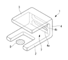
- the space securing device 1 is an integral member including a heart pressing portion 2 that contacts the surface of the heart A, a pericardial pressing portion 3 that contacts the inner surface of the pericardium B, and a connecting portion 4 that connects them.
- the heart pressing portion 2 is a substantially U-shaped flat plate portion.
- the heart pressing unit 2 is disposed at a position that partially surrounds the periphery of the range (for example, diseased site D) to be treated by the treatment tool 6 while being observed with the endoscope 5.
- the pericardial pressing part 3 is, for example, a rectangular flat plate part as shown in FIG. As shown in FIG. 1, the pericardial pressing unit 3 presses the pericardium B with the outer surface. As shown in FIG. 1, the surface opposite to the outer surface of the pericardial pressing portion 3 is coated with a reflective film 3a so that the light L can be reflected.
- the connecting part 4 is a part that connects the one end of the heart pressing part 2 and the pericardial pressing part 3.
- the connecting portion 4 includes a through hole 4a into which the endoscope 5 can be inserted, and a through hole 4b into which the treatment tool 6 can be inserted.
- the through-hole 4a for the endoscope 5 extends from the outside of the space securing device 1 into the space 7 formed between the heart pressing part 2 and the pericardial pressing part 3 in a direction away from the heart pressing part 2. Inclined. Thereby, the front end surface 5a of the endoscope 5 inserted from the outside can be easily arranged obliquely upward.
- the through-hole 4b for the treatment instrument 6 may be inclined in a direction away from the pericardial pressing portion 3 from the outside of the space securing device 1 into the space 7.
- the space securing device 1 includes, for example, a contracted state that can be accommodated in a sheath (guide tube) 8 inserted into the pericardial cavity C from the lower part of the xiphoid process, As shown in FIG. 3, the push rod 9 inserted into the sheath 8 from the proximal end side can be expanded and contracted between the expanded state released by being pushed out of the sheath 8. In the expanded state, the space securing device 1 is expanded by a preset elasticity. Therefore, the space securing device 1 forms a sufficient space 7 without unnecessarily expanding the interval between the pericardium B and the heart A.
- the space securing device 1 configured as described above will be described below.
- a diseased part D of the heart A for example, a boundary region between a myocardial infarction part and a normal part
- the distal end portion of the sheath 8 accommodated in a state where the space securing device 1 is contracted in the vicinity is inserted into the pericardial cavity C as shown in FIG. In this state, the region where the pericardium B and the heart A are separated is limited to the vicinity of the distal end portion of the sheath 8.
- the space securing device 1 accommodated in the sheath 8 is pushed out of the sheath 8 by the push rod 9 introduced from the proximal end side of the sheath 8 as shown in FIG.
- the heart pressing part 2 is arranged at a position surrounding the disease site D as shown in FIG. Since the space securing device 1 is made of an elastic material, it is expanded by its elastic force.
- the pericardium B is pressed by the pericardial pressing unit 3 and the heart A is pressed by the cardiac pressing unit 2, so that the interval between the pericardial B and the heart A can be enlarged in the vicinity of the diseased site D.
- the space securing device 1 is expanded by a preset elasticity in the expanded state. Therefore, a sufficient space 7 can be formed without unnecessarily expanding the interval between the pericardium B and the heart A.
- the endoscope 5 and the treatment tool 6 are guided into the pericardial cavity C through the sheath 8.
- the endoscope 5 is inserted from the heart A side through-hole 4 a provided in the connecting portion 4, the treatment tool 6 is inserted from the pericardium B-side through hole 4 b, and the heart pressing unit 2 and the pericardial pressing unit 3. It inserts in the space 7 formed between.
- the through hole 4a for the endoscope 5 is inclined in a direction away from the heart pressing portion 2 toward the space 7. Therefore, the endoscope 5 inserted into the through hole 4a is easily guided so that the distal end surface 5a is directed obliquely upward.
- illumination light is irradiated from the front end surface 5a.
- the illumination light is reflected to the surface side of the heart A by the reflecting surface 3a provided on the pericardial pressing part 3, and illuminates the surface of the heart A.
- return light such as fluorescence and reflected light returning from the surface of the heart A is collected by an objective lens (not shown) provided on the distal end surface 5a of the endoscope 5 via the reflection surface 3a.
- the optical path from the distal end surface 5a of the endoscope 5 to the surface of the heart A is folded back by the reflecting surface 3a.
- the distance from the distal end surface 5a of the endoscope 5 to the surface of the heart A can be ensured without increasing the distance between the pericardium B and the heart A more than necessary. Therefore, the diseased part D can be sufficiently illuminated and observed without excessively diffusing the illumination light. As a result, complications such as cardiac tamponade can be suppressed.
- Stem cells and the like can be injected by reliably puncturing the injection needle 6a at the tip of the tool 6 in the boundary region between the diseased site D and the normal site.
- the space securing device 1 is grasped by forceps (not shown) introduced through the inside of the sheath 8 and pulled into the sheath 8 while being deformed, so that it can be easily recovered.
- the through-hole 4b into which the treatment tool 6 is inserted is inclined in the direction away from the pericardial pressing portion 3 from the outside of the space securing device 1 into the space 7, thereby
- the injection needle 6a can be easily directed to the diseased site D.
- part D is reflected by the reflective surface 3a, it becomes an inverted image as an acquired image. Therefore, it is preferable to perform image inversion processing by an image processing unit (not shown) connected to the proximal end side of the endoscope 5.
- the space securing device 1 can be made to function as a member that suppresses the force applied by the pulsation of the heart A or the influence of respiration. That is, the heart pressing part 2 in contact with the heart A is made of a soft and easy-to-restore silicone resin or polyurethane resin, and the pericardial pressing part 3 in contact with the pericardium B is made of a hard and hardly deformable material such as PTFE or polyethylene. It may be configured. Moreover, it is good also as a reverse structure.
- the contracted space securing device 1 accommodated in the sheath 8 is expanded from the sheath 8 by being pushed out from the sheath 8, but instead of this, a forceps channel provided in the endoscope 5 is used.
- the contracted space securing device 1 accommodated in (not shown) may be pushed out from the forceps channel.
- an X-ray opaque material is mixed in the silicone resin or the like constituting the space securing device 1.
- space securing device 10-1 according to a second embodiment of the present invention will be described below with reference to the drawings.
- portions having the same configuration as the space securing device 1 according to the first embodiment described above are denoted by the same reference numerals and description thereof is omitted.
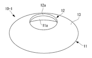
- the space securing device 10-1 is a bowl-shaped member as shown in FIGS.
- the space securing device 10-1 includes a heart pressing portion 11 having a wide-mouthed heart-side opening 11a made of an elastic material such as silicone resin, and a pericardial pressing portion 12 having a narrow-mouthed pericardial-side opening 12a. And an annular connecting portion 13 for connecting them.
- the pericardial opening 12a has a sufficient diameter to allow the distal end of the endoscope 5 to enter the inside from the outside.
- the heart side opening 11a has a sufficient diameter to surround the diseased site D to be observed and treated.
- the connecting portion 13 has an outer surface made of a spherical curved surface that is convex outward.
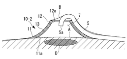
- the space securing device 10-1 according to the present embodiment also has a contracted state that can be accommodated in the sheath 8, and an expanded state in which the space between the surface of the heart A and the pericardium B is expanded by being released from the sheath 8 and expanding. And can be deformed between.
- the space securing device 10-1 In order to observe and treat the disease site D of the heart A using the space securing device 10-1 according to the present embodiment, the space securing device 10-1 is housed in a contracted state as in the first embodiment.
- the sheath 8 is inserted into the pericardial cavity C, and the space securing device 10-1 is pushed out of the sheath 8 so that the heart side opening portion 11a is expanded at a position surrounding the disease site D.
- the heart pressing portion 11 is in close contact with the surface of the heart A, and the heart side opening portion 11a is blocked by the surface of the heart A.
- the pericardial pressing portion 12 is in close contact with the inner surface of the pericardium B, and the pericardial opening 12 a is blocked by the inner surface of the pericardium B.
- the endoscope 5 guided into the pericardial cavity C through the sheath 8 is moved forward on the outer surface of the space securing device 10-1.
- the endoscope 5 is slid between the pericardium B and the pericardial pressing part 12 that have blocked the pericardial opening 12a, and the peripheries of the pericardium It is possible to easily enter the space 7 from the side opening 12a.
- the distal end portion of the endoscope 5 is disposed at a position sufficiently separated from the surface of the heart A, and the bending operation of the bending portion can be freely performed in the space 7. Therefore, there is an advantage that the diseased part D can be easily observed without hindering the operability of the endoscope 5. Furthermore, there is an advantage that treatment with the treatment tool 6 guided separately from the endoscope 5 or through the forceps channel of the endoscope 5 can be easily performed.
- the space securing device 10-1 since the outer surface is formed of a curved surface that is convex outward, the endoscope 5 can be easily curved along the outer surface. Therefore, the operation of the endoscope 5 when entering the pericardial opening 12a can be facilitated.
- the curved surface shape may be concave on the outside.
- the inclination angle of the outer surface of the connecting portion 13 can be suppressed at the position rising from the surface of the heart A, and the endoscope 5 can be easily placed on the outer surface of the space securing device 10-2.
- the space securing devices 10-1 and 10-2 shown in FIGS. 6 and 7 are formed in a thin cylindrical shape, but instead, as shown in FIGS.
- a planar triangular space securing device 10-3 may be employed. Also in this case, you may provide the inclined surface 14 so that it may become thick as an outer surface from an outer peripheral side toward an inner peripheral side.
- annular space securing device 10-4 having a circular or substantially elliptical cross-sectional shape may be employed. Also by these, as shown in FIG. 11, a certain amount of space 7 for the operation of the endoscope 5 can be easily secured between the pericardium B and the surface of the heart A. An ear portion (not shown) that protrudes to the outer peripheral side may be provided so as to be easily gripped at the time of collection.
- a space securing device 10-5 having one or more grooves 15 extending on the outer surface of the connecting portion 13 so as to connect the outer peripheral side and the inner peripheral side is adopted. Also good. By doing in this way, there exists an advantage that the endoscope 5 can be easily guide
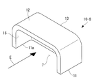
- the space pressing devices 10-6 and 10-7 having a substantially U-shaped configuration may be employed for the heart pressing portion 11 without being closed in an annular shape.
- the space securing device 10-6 may be hollow inside.
- the connecting portion 13 is partially opened to form the opening 16. Therefore, as indicated by an arrow E in the figure, the endoscope 5 and the treatment tool 6 can be made to enter the space 7 surrounded by the space securing device 10 via the opening 16.
- an inclined surface (guiding table) that floats the distal end portion of the endoscope 5 that is allowed to enter the space 7 from the surface of the heart A. 17 may be provided in the heart pressing portion 11.
- a groove 18 is provided on the inclined surface 17.
- FIG. 19 is an example in which an inclined surface 17 is provided on the heart pressing portion 11 so as to float the distal end portion of the endoscope 5 that enters the space 7 from the surface of the heart A.
- the inclined surface 17 may have a groove 18 similar to that shown in FIG.
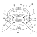
- the connecting portion 13 may be constituted by a plurality of support columns to constitute a bowl-shaped space securing device 10-9.
- the inclined surface 17 is provided in the heart pressing portion 11 in each opening portion 16 provided between the connecting portions 13 made of struts.
- the space securing device (here, the space securing device 10-6 will be described as an example) includes the space securing device 10-6 including a plurality of small pieces 10a.
- the cross-sectional area is sufficiently small so that it can be easily cut by the forceps F or the like.
- the cut piece 10a of the space securing device 10-6 that has been cut can be easily pulled into the sheath 8 while observing with the endoscope 5. Therefore, there is an advantage that the collection operation can be facilitated.
- the dividing line 19 may be applied to other space securing devices 1, 10-1 to 10-9.
- the space securing devices 1, 10-1 to 10-9 made of an elastic material such as a silicone resin have been described as examples, but instead of this, FIGS. 25 to 30 are used.
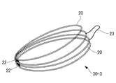
- space securing devices 30-1 to 30-3 configured by wires made of a metal material or a resin material may be employed.
- the space securing device 30-1 shown in FIG. 25 and FIG. 26 has four ring-shaped wires 20 connected to each other by a tube 21 or the like so as to be relatively movable.
- the space securing device 30-1 can be deformed between a contracted state shown in FIG. 26 and an expanded state shown in FIG.
- the space securing device 30-1 can be easily introduced into the pericardial cavity C by the sheath 8 or the like in the contracted state shown in FIG. After being released from the sheath 8, the space securing device 30-1 is in an expanded state as shown in FIG. 25 and is configured to expand the space 7 between the pericardium B and the heart A.
- the wire 20 may be made of a shape memory material.
- the sheath 8 is cooled and maintained in the contracted state shown in FIG. 26, and after being introduced into the pericardial cavity C, the body 8 is brought into the expanded state shown in FIG. You may decide.
- As a cooling method a method using a Peltier element or a low temperature medium such as liquid nitrogen can be sprayed. Furthermore, since it will be in the contracted state of FIG. 26 only by cooling at the time of collection, it can be easily collected.
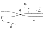
- FIG. 27 shows the expanded state of the space securing device 30-2.
- the space 7 can be stably formed in the pericardial cavity C when the portion connected by the thread 23 is the heart pressing portion 11 and the joint portion 22 is the pericardial pressing portion 12.
- Such a space securing device 30-2 can be folded small by being folded and can be easily accommodated in the sheath 8.
- the securing device 30-3 may be adopted.
- the space 7 is stably formed in the pericardial cavity C. be able to.
- such a space securing device 30-3 can be folded small by folding and can be easily accommodated in the sheath 8.
- the position surrounded by the broken line G in FIG. 30 is cut with a forceps F or the like, so that the two annular wires 20 are simply stacked. And can be easily collected in the sheath 8.
- FIGS. 31 and 32 a space securing device (here, space securing devices 10-3 and 10-1 will be described as an example) provided with suction means for attracting the heart pressing portion 11 to the surface of the heart A. May be adopted.
- the example shown in FIG. 31 shows the space securing device 10-3 having the suction hole 24 that opens to the contact surface of the heart pressing portion 11 to the surface of the heart A as the suction means.
- a communication hole 25 for supplying a negative pressure and a tube 26 are connected to the suction hole 24.
- the heart pressing portion 11 can be adsorbed and fixed on the surface of the heart A by the adsorption hole 24.
- Observation and treatment can be performed stably by adsorbing and fixing at a desired position surrounding the disease site D.
- a probe 28 having a magnet 27 at the tip is disposed in the heart A, and a magnetic material 29 is disposed on the heart pressing portion 11 of the space securing device 10-1.
- the heart pressing portion 11 can be attracted and fixed to the surface of the heart A by the magnetic attraction generated between the magnet 27 and the magnetic material 29.
- a magnet may be arranged. In this case, either a magnet or a magnetic material may be disposed at the tip of the probe 28.
- a bioadhesive may be used to fix the heart pressing part 11 to the heart A surface.
- a magnet (not shown) that generates a magnetic repulsive force between the magnet 27 and the magnet 27 disposed in the heart A may be disposed in the heart pressing portion 11, or an adhesive, negative pressure suction, gripping, or You may employ
Landscapes
- Health & Medical Sciences (AREA)
- Life Sciences & Earth Sciences (AREA)
- Surgery (AREA)
- Heart & Thoracic Surgery (AREA)
- Veterinary Medicine (AREA)
- Public Health (AREA)
- General Health & Medical Sciences (AREA)
- Engineering & Computer Science (AREA)
- Biomedical Technology (AREA)
- Animal Behavior & Ethology (AREA)
- Molecular Biology (AREA)
- Medical Informatics (AREA)
- Nuclear Medicine, Radiotherapy & Molecular Imaging (AREA)
- Pathology (AREA)
- Oral & Maxillofacial Surgery (AREA)
- Child & Adolescent Psychology (AREA)
- Biophysics (AREA)
- Pulmonology (AREA)
- Anesthesiology (AREA)
- Hematology (AREA)
- Endoscopes (AREA)
Abstract
Dans une opération d'endoscopie péricardiaque, l'espace requis pour la manipulation d'un endoscope ou d'un instrument de traitement peut être formé sans prévoir un moyen spécifique de formation d'espace sur l'endoscope ou l'instrument de traitement et sans devoir inutilement dilater la cavité du péricarde, de manière à améliorer les propriétés de manipulation tout en empêchant l'apparition d'une maladie de complication, par exemple un tamponnage cardiaque. L'invention concerne un dispositif de formation d'espace qui comprend une partie de poussée du péricarde qui repousse le péricarde du côté de la cavité du péricarde, une partie de poussée du coeur qui repousse la surface du coeur du côté de la cavité du péricarde et une partie de liaison qui relie ladite partie de poussée du péricarde à ladite partie de poussée du coeur, la partie de liaison exerçant une force élastique qui permet une dilatation en opposition aux poussées appliquées par le péricarde et le coeur pour ainsi former un espace entre ladite partie de poussée du péricarde et ladite partie de poussée du coeur.
Priority Applications (2)
| Application Number | Priority Date | Filing Date | Title |
|---|---|---|---|
| CN201080052840.2A CN102665615B (zh) | 2009-09-22 | 2010-09-16 | 空间确保装置 |
| EP10818743.6A EP2481377A4 (fr) | 2009-09-22 | 2010-09-16 | Dispositif de formation d'espace |
Applications Claiming Priority (4)
| Application Number | Priority Date | Filing Date | Title |
|---|---|---|---|
| US24458609P | 2009-09-22 | 2009-09-22 | |
| US61/244586 | 2009-09-22 | ||
| JP2010-119749 | 2010-05-25 | ||
| JP2010119749A JP5717986B2 (ja) | 2009-09-22 | 2010-05-25 | 空間確保デバイス |
Publications (1)
| Publication Number | Publication Date |
|---|---|
| WO2011037068A1 true WO2011037068A1 (fr) | 2011-03-31 |
Family
ID=46319963
Family Applications (1)
| Application Number | Title | Priority Date | Filing Date |
|---|---|---|---|
| PCT/JP2010/066061 WO2011037068A1 (fr) | 2009-09-22 | 2010-09-16 | Dispositif de formation d'espace |
Country Status (4)
| Country | Link |
|---|---|
| US (1) | US8808173B2 (fr) |
| EP (1) | EP2481377A4 (fr) |
| CN (1) | CN102665615B (fr) |
| WO (1) | WO2011037068A1 (fr) |
Families Citing this family (8)
| Publication number | Priority date | Publication date | Assignee | Title |
|---|---|---|---|---|
| JP2013103075A (ja) * | 2011-11-16 | 2013-05-30 | Olympus Corp | 誘導型医療システム |
| AU2015229719B2 (en) | 2014-03-10 | 2017-04-06 | Stryker Corporation | Limb positioning system |
| CN104055548B (zh) * | 2014-07-10 | 2016-03-02 | 张自雄 | 由磁力牵引活动建腔适于颈部内镜手术的装置 |
| US9951904B2 (en) | 2015-03-24 | 2018-04-24 | Stryker Corporation | Rotatable seat clamps for rail clamp |
| JPWO2017203582A1 (ja) | 2016-05-23 | 2019-04-11 | オリンパス株式会社 | 内視鏡用デバイスおよび内視鏡システム |
| US10750936B2 (en) * | 2017-11-02 | 2020-08-25 | Olympus Corporation | Pericardial-cavity observing method |
| JP6964766B2 (ja) | 2018-04-26 | 2021-11-10 | オリンパス株式会社 | 処置システムおよび拡張デバイス |
| WO2022213334A1 (fr) * | 2021-04-09 | 2022-10-13 | Covidien Lp | Appareil de support de tissu pour intervention chirurgicale laparoscopique |
Citations (7)
| Publication number | Priority date | Publication date | Assignee | Title |
|---|---|---|---|---|
| JPH06507810A (ja) * | 1991-05-29 | 1994-09-08 | オリジン・メドシステムズ・インク | 内視鏡型拡張式レトラクション装置の用法と製作法 |
| JPH07501959A (ja) * | 1991-11-19 | 1995-03-02 | オリジン・メドシステムズ・インク | 組織層を分離するための内視鏡的膨脹式開創装置および使用方法 |
| JPH0975353A (ja) * | 1995-07-07 | 1997-03-25 | Olympus Optical Co Ltd | 腔確保具 |
| JPH10234738A (ja) * | 1997-02-27 | 1998-09-08 | Masao Takahashi | 冠状動脈のバイパス手術に用いる血管吻合部の止血保持装置 |
| JP2000023988A (ja) * | 1998-05-28 | 2000-01-25 | Krajicek Milan | 心筋安定装置 |
| JP2003529390A (ja) * | 1999-04-16 | 2003-10-07 | メディヴァス,エルエルシー. | 治療部位の安定化装置およびその使用方法 |
| US20040064138A1 (en) | 2000-10-05 | 2004-04-01 | Grabek James R. | Atrial appendage remodeling device and method |
Family Cites Families (124)
| Publication number | Priority date | Publication date | Assignee | Title |
|---|---|---|---|---|
| US3281141A (en) * | 1963-01-15 | 1966-10-25 | American Sterilizer Co | Surgical table |
| US3859985A (en) * | 1973-06-27 | 1975-01-14 | Becton Dickinson Co | Angiography valve |
| US4063553A (en) * | 1976-04-08 | 1977-12-20 | Bell & Howell Company | Pressure transducing methods and apparatus |
| US4224929A (en) * | 1977-11-08 | 1980-09-30 | Olympus Optical Co., Ltd. | Endoscope with expansible cuff member and operation section |
| US4319568A (en) * | 1979-10-29 | 1982-03-16 | Vickers Limited | Liquid dispensing apparatus |
| GB8424101D0 (en) * | 1984-09-24 | 1984-10-31 | Vi Tal Hospital Products Ltd | Air-in-line detector |
| JPS6235318A (ja) | 1985-08-09 | 1987-02-16 | Canon Inc | 内視鏡操作方法 |
| US5035231A (en) * | 1987-04-27 | 1991-07-30 | Olympus Optical Co., Ltd. | Endoscope apparatus |
| JP2575395B2 (ja) | 1987-07-15 | 1997-01-22 | オリンパス光学工業株式会社 | Nmr計測用アンテナ装置 |
| US4884567A (en) * | 1987-12-03 | 1989-12-05 | Dimed Inc. | Method for transvenous implantation of objects into the pericardial space of patients |
| JPH0255960A (ja) | 1988-08-20 | 1990-02-26 | Fujikura Ltd | 光電流センサ |
| US4991603A (en) * | 1989-10-30 | 1991-02-12 | Siemens-Pacesetter, Inc. | Transvenously placed defibrillation leads via an inferior vena cava access site and method of use |
| JP2870876B2 (ja) | 1989-10-31 | 1999-03-17 | トッパン・フォームズ株式会社 | 隠蔽部材を有するカードの作成方法 |
| US5048537A (en) * | 1990-05-15 | 1991-09-17 | Medex, Inc. | Method and apparatus for sampling blood |
| US5370134A (en) * | 1991-05-29 | 1994-12-06 | Orgin Medsystems, Inc. | Method and apparatus for body structure manipulation and dissection |
| US7744617B2 (en) * | 1991-05-29 | 2010-06-29 | Covidien Ag | Method and inflatable chamber apparatus for separating layers of tissue |
| US5795325A (en) * | 1991-07-16 | 1998-08-18 | Heartport, Inc. | Methods and apparatus for anchoring an occluding member |
| US5336252A (en) * | 1992-06-22 | 1994-08-09 | Cohen Donald M | System and method for implanting cardiac electrical leads |
| US5297536A (en) * | 1992-08-25 | 1994-03-29 | Wilk Peter J | Method for use in intra-abdominal surgery |
| US5324266A (en) * | 1992-12-23 | 1994-06-28 | Abbott Laboratories | In-line sampling system incorporating an improved blood sampling device |
| US5400773A (en) * | 1993-01-19 | 1995-03-28 | Loma Linda University Medical Center | Inflatable endoscopic retractor |
| US6478029B1 (en) * | 1993-02-22 | 2002-11-12 | Hearport, Inc. | Devices and methods for port-access multivessel coronary artery bypass surgery |
| US5725525A (en) * | 1993-03-16 | 1998-03-10 | Ep Technologies, Inc. | Multiple electrode support structures with integral hub and spline elements |
| SE9303253D0 (sv) | 1993-10-05 | 1993-10-05 | Siemens Elema Ab | Instrument för titthålskirurgi |
| US5522804A (en) * | 1994-02-15 | 1996-06-04 | Lynn; Lawrence A. | Aspiration, mixing, and injection syringe |
| US5846261A (en) * | 1994-07-08 | 1998-12-08 | Aga Medical Corp. | Percutaneous catheter directed occlusion devices |
| JPH08117232A (ja) | 1994-10-24 | 1996-05-14 | Olympus Optical Co Ltd | 穿刺具 |
| JPH08280815A (ja) | 1995-04-19 | 1996-10-29 | Sumitomo Bakelite Co Ltd | ステントデリバリー用カテーテル |
| US5827216A (en) | 1995-06-07 | 1998-10-27 | Cormedics Corp. | Method and apparatus for accessing the pericardial space |
| US5759150A (en) * | 1995-07-07 | 1998-06-02 | Olympus Optical Co., Ltd. | System for evulsing subcutaneous tissue |
| US5836311A (en) | 1995-09-20 | 1998-11-17 | Medtronic, Inc. | Method and apparatus for temporarily immobilizing a local area of tissue |
| US5697916A (en) * | 1995-11-21 | 1997-12-16 | Stat Medical Devices Inc. | Hypodermic dosage measuring device |
| CA2197614C (fr) * | 1996-02-20 | 2002-07-02 | Charles S. Taylor | Instruments chirurgicaux et procedes de stabilisation du coeur palpitant en cours de pontage aortocoronarien |
| US5894843A (en) * | 1996-02-20 | 1999-04-20 | Cardiothoracic Systems, Inc. | Surgical method for stabilizing the beating heart during coronary artery bypass graft surgery |
| ES2128936B1 (es) | 1996-05-22 | 2000-01-16 | Patentes Novedades Sa | Procedimiento para la obtencion de pentaeritritol. |
| US6059750A (en) * | 1996-08-01 | 2000-05-09 | Thomas J. Fogarty | Minimally invasive direct cardiac massage device and method |
| JP3017451B2 (ja) | 1996-11-11 | 2000-03-06 | オリンパス光学工業株式会社 | 内視鏡用フード |
| US5931810A (en) | 1996-12-05 | 1999-08-03 | Comedicus Incorporated | Method for accessing the pericardial space |
| US5735791A (en) * | 1997-01-31 | 1998-04-07 | Research Medical, Inc. | Inflatable heart elevation apparatus and method |
| GB9900964D0 (en) * | 1999-01-15 | 1999-03-10 | Gyrus Medical Ltd | An electrosurgical system |
| US6390976B1 (en) * | 1997-09-17 | 2002-05-21 | Origin Medsystems, Inc. | System to permit offpump beating heart coronary bypass surgery |
| US6592552B1 (en) | 1997-09-19 | 2003-07-15 | Cecil C. Schmidt | Direct pericardial access device and method |
| US5968017A (en) * | 1997-10-14 | 1999-10-19 | Merit Medical Systems, Inc. | Pulse fluid infusion systems |
| US6015382A (en) * | 1997-10-16 | 2000-01-18 | General Surgical Innovations, Inc. | Inflatable manipulator for organ positioning during surgery and method of use |
| US6017332A (en) * | 1997-10-20 | 2000-01-25 | Urrutia; Hector | Medical dye delivery system |
| US6267717B1 (en) * | 1998-03-31 | 2001-07-31 | Advanced Research & Technology Institute | Apparatus and method for treating a body structure with radiation |
| JPH11276422A (ja) | 1998-03-31 | 1999-10-12 | Fuji Photo Optical Co Ltd | 超音波内視鏡 |
| US6740082B2 (en) * | 1998-12-29 | 2004-05-25 | John H. Shadduck | Surgical instruments for treating gastro-esophageal reflux |
| CA2333149A1 (fr) | 1998-05-26 | 1999-12-02 | Comedicus Incorporated | Procedures et appareils d'exploration intrapericardique |
| US6309374B1 (en) | 1998-08-03 | 2001-10-30 | Insite Vision Incorporated | Injection apparatus and method of using same |
| JP2000176011A (ja) | 1998-12-18 | 2000-06-27 | Urrutia Hector | 医療用色素送出システム |
| US6977080B1 (en) * | 1999-08-10 | 2005-12-20 | Allergan, Inc. | Intrapericardial botulinum toxin treatment for bradycardia |
| US7398781B1 (en) * | 1999-08-10 | 2008-07-15 | Maquet Cardiovascular, Llc | Method for subxiphoid endoscopic access |
| US7526342B2 (en) * | 1999-08-10 | 2009-04-28 | Maquet Cardiovascular Llc | Apparatus for endoscopic cardiac mapping and lead placement |
| US6517477B1 (en) * | 2000-01-27 | 2003-02-11 | Scimed Life Systems, Inc. | Catheter introducer system for exploration of body cavities |
| AU782618B2 (en) | 2000-04-12 | 2005-08-11 | Covidien Ag | Thoracentesis device with hyper-sensitive detection mechanism |
| US6471644B1 (en) * | 2000-04-27 | 2002-10-29 | Medtronic, Inc. | Endoscopic stabilization device and method of use |
| JP4517321B2 (ja) | 2000-06-05 | 2010-08-04 | 有限会社エスアールジェイ | オーバーチューブ |
| JP2002017854A (ja) | 2000-07-11 | 2002-01-22 | Daiken Iki Kk | 薬液注入装置の流量調節器 |
| US6890295B2 (en) * | 2002-10-31 | 2005-05-10 | Medtronic, Inc. | Anatomical space access tools and methods |
| US6786898B2 (en) * | 2003-01-15 | 2004-09-07 | Medtronic, Inc. | Methods and tools for accessing an anatomic space |
| US6706013B1 (en) * | 2001-06-29 | 2004-03-16 | Advanced Cardiovascular Systems, Inc. | Variable length drug delivery catheter |
| JP4768154B2 (ja) * | 2001-06-29 | 2011-09-07 | テルモ株式会社 | 医療用エネルギー照射装置 |
| WO2003039354A1 (fr) * | 2001-10-18 | 2003-05-15 | Atropos Limited | Dispositif destiné à faciliter l'introduction d'un colonoscope |
| JP3859491B2 (ja) | 2001-11-15 | 2006-12-20 | オリンパス株式会社 | 内視鏡用シース |
| US7749157B2 (en) * | 2001-12-04 | 2010-07-06 | Estech, Inc. (Endoscopic Technologies, Inc.) | Methods and devices for minimally invasive cardiac surgery for atrial fibrillation |
| JP2004033525A (ja) | 2002-07-04 | 2004-02-05 | Fuji Photo Optical Co Ltd | 硬度可変処置具 |
| AU2003258062A1 (en) | 2002-08-05 | 2004-02-23 | Infraredx, Inc. | Near-infrared spectroscopic analysis of blood vessel walls |
| JP4385118B2 (ja) | 2002-08-07 | 2009-12-16 | 独立行政法人産業技術総合研究所 | 穿針装置及び該穿針装置の針の動作状態の検出方法 |
| JP4334838B2 (ja) | 2002-09-06 | 2009-09-30 | オリンパス株式会社 | 内視鏡装置 |
| JP4088918B2 (ja) | 2002-09-13 | 2008-05-21 | 東レ・メディカル株式会社 | 血液透析装置 |
| CA2511958C (fr) * | 2003-01-21 | 2014-04-08 | Metech S.R.L. | Ecarteur pour operations chirurgicales sur l'arteria haemorrhoidalis |
| US7394976B2 (en) * | 2003-03-25 | 2008-07-01 | Arizant Healthcare Inc. | Fluid warming cassette and system capable of operation under negative pressure |
| JP4274073B2 (ja) * | 2003-08-08 | 2009-06-03 | 住友ベークライト株式会社 | 冠状動脈バイパス術用処置具 |
| CA2439667A1 (fr) * | 2003-09-04 | 2005-03-04 | Andrew Kenneth Hoffmann | Systeme et appareil de perfusion sanguine assistes d'un dispositif produisant des vibrations a basse frequence |
| US7341558B2 (en) * | 2003-09-19 | 2008-03-11 | Medcanica, Llc | Pericardial retractor |
| WO2005028001A1 (fr) * | 2003-09-23 | 2005-03-31 | Gambro Lundia Ab | Appareil, systeme et procedes associes a l'hemodialyse, a l'hemodiafiltration, a l'hemofiltration ou a la dialyse peritoneale |
| US20050159645A1 (en) * | 2003-11-12 | 2005-07-21 | Bertolero Arthur A. | Balloon catheter sheath |
| JP2005169009A (ja) * | 2003-12-15 | 2005-06-30 | Olympus Corp | 内視鏡システム、及び内視鏡 |
| US7399272B2 (en) * | 2004-03-24 | 2008-07-15 | Medtronic, Inc. | Methods and apparatus providing suction-assisted tissue engagement |
| WO2005110192A1 (fr) * | 2004-05-14 | 2005-11-24 | Olympus Corporation | Dispositif d'insertion |
| US8926635B2 (en) * | 2004-06-18 | 2015-01-06 | Medtronic, Inc. | Methods and devices for occlusion of an atrial appendage |
| US7229408B2 (en) * | 2004-06-30 | 2007-06-12 | Ethicon, Inc. | Low profile surgical retractor |
| ITBO20040443A1 (it) * | 2004-07-16 | 2004-10-16 | Cefla Coop | Divaricatore per cavo orale |
| JP2008521523A (ja) | 2004-12-02 | 2008-06-26 | ブラッドリー・エイチ・ストラウス | 慢性完全閉塞部におけるガイドワイヤーの通過を容易にし、促進するための管腔内微細血管形成の増強 |
| JP2007306944A (ja) * | 2005-01-21 | 2007-11-29 | Olympus Corp | 内視鏡及び内視鏡用医療器具並びにその表示方法 |
| US20080015569A1 (en) * | 2005-02-02 | 2008-01-17 | Voyage Medical, Inc. | Methods and apparatus for treatment of atrial fibrillation |
| JP2006271831A (ja) | 2005-03-30 | 2006-10-12 | Terumo Corp | 医療用治療装置およびその装置の使用方法 |
| US20060259017A1 (en) * | 2005-04-27 | 2006-11-16 | Cardiac Pacemakers, Inc. | Adhesive elements and methods for accessing the pericardial space |
| EP1879516A4 (fr) * | 2005-05-02 | 2010-02-03 | Kinetic Spine Technologies Inc | Implant de stabilisation des vertebres |
| US20080167621A1 (en) * | 2005-05-16 | 2008-07-10 | Wagner Gary S | Multi-Barrel Syringe Having Integral Manifold |
| US20070088203A1 (en) * | 2005-05-25 | 2007-04-19 | Liming Lau | Surgical assemblies and methods for visualizing and performing surgical procedures in reduced-access surgical sites |
| US7837688B2 (en) * | 2005-06-13 | 2010-11-23 | Globus Medical | Spinous process spacer |
| JP2007029556A (ja) * | 2005-07-28 | 2007-02-08 | Olympus Corp | 医療装置用挿入補助具 |
| JP2007054333A (ja) | 2005-08-25 | 2007-03-08 | Pentax Corp | Octプローブ、及び、octシステム |
| US20070135686A1 (en) * | 2005-12-14 | 2007-06-14 | Pruitt John C Jr | Tools and methods for epicardial access |
| EP1968466A2 (fr) * | 2005-12-19 | 2008-09-17 | M. S. Abdou | Dispositifs et procédés de mise en place d'un dispositif orthopédique intervertébral |
| WO2007078003A1 (fr) * | 2006-01-06 | 2007-07-12 | Olympus Medical Systems Corp. | Systeme medical a travers une ouverture naturelle ou transcutane |
| JP5116985B2 (ja) * | 2006-04-13 | 2013-01-09 | 富士フイルム株式会社 | 内視鏡 |
| US8342183B2 (en) * | 2006-04-19 | 2013-01-01 | Vibrynt, Inc. | Devices and methods for treatment of obesity |
| CA2910478C (fr) * | 2006-05-18 | 2017-02-28 | Smart Medical Systems Ltd. | Systeme et fonctionnalite d'endoscope souple |
| US20070270882A1 (en) * | 2006-05-19 | 2007-11-22 | Acorn Cardiovascular, Inc. | Pericardium management method for intra-pericardial surgical procedures |
| US8092470B2 (en) * | 2006-06-08 | 2012-01-10 | Olympus Medical Systems Corp. | Calculus crushing apparatus and medical procedure using endoscope |
| US8821376B2 (en) * | 2007-03-12 | 2014-09-02 | David Tolkowsky | Devices and methods for performing medical procedures in tree-like luminal structures |
| JP2008259701A (ja) * | 2007-04-12 | 2008-10-30 | Olympus Corp | 生体内挿入器具 |
| FR2914840A1 (fr) | 2007-04-16 | 2008-10-17 | Lk2 Soc Responsabilite Limitee | Procede de prelevement sanguin, et branchement pour un dispositif de prelevement sanguin. |
| EP2148608A4 (fr) | 2007-04-27 | 2010-04-28 | Voyage Medical Inc | Cathéter pour la visualisation et la manipulation de tissus man uvrables de formes complexes |
| US9901710B2 (en) * | 2007-04-27 | 2018-02-27 | Cvdevices, Llc | Steering engagement catheter devices, systems, and methods |
| US20080275294A1 (en) * | 2007-05-01 | 2008-11-06 | Michael Gertner | Pericardial inserts |
| JP2008284108A (ja) * | 2007-05-16 | 2008-11-27 | Olympus Corp | スタビライザ |
| US20080294174A1 (en) * | 2007-05-21 | 2008-11-27 | Epitek, Inc. | Methods and apparatus for pericardial access |
| EP2157996B1 (fr) * | 2007-05-21 | 2019-07-24 | Smart Medical Systems Ltd. | Cathéter comprenant une partie pouvant être courbée |
| KR101487425B1 (ko) * | 2007-06-29 | 2015-01-29 | 가부시끼가이샤 제이엠에스 | 혈액 투석 장치 |
| JP5011024B2 (ja) * | 2007-08-10 | 2012-08-29 | オリンパスメディカルシステムズ株式会社 | 内視鏡 |
| US8311620B2 (en) * | 2007-08-22 | 2012-11-13 | Cardiac Pacemakers, Inc. | Methods and apparatus to treat and prevent atrial tachyarrhythmias |
| US8545387B2 (en) * | 2007-11-05 | 2013-10-01 | Corinnova Incorporated | Apparatus and method for minimally invasive implantation of heart assist device |
| WO2009092021A1 (fr) * | 2008-01-17 | 2009-07-23 | Nidus Medical, Llc | Accès à la partie inférieure de l'œsophage et systèmes de traitement |
| WO2009132009A1 (fr) * | 2008-04-21 | 2009-10-29 | Medtronic, Inc. | Dispositif d'ablation à force d'aspiration |
| US8690762B2 (en) * | 2008-06-18 | 2014-04-08 | Raytheon Company | Transparent endoscope head defining a focal length |
| CN102264309B (zh) * | 2008-10-10 | 2014-01-29 | 瑟吉奎斯特有限公司 | 具有固定装置的低矮轮廓式外科进入装置 |
| EP2378990B1 (fr) * | 2008-12-22 | 2018-05-16 | Synthes GmbH | Élément d'espacement de traitement intervertébral agrandissable |
| US20100268029A1 (en) * | 2009-04-21 | 2010-10-21 | Xlumena, Inc. | Methods and apparatus for advancing a device from one body lumen to another |
| US20100317925A1 (en) * | 2009-06-12 | 2010-12-16 | Banchieri Michael J | Suction-assisted tissue stabilizers |
| WO2011041638A2 (fr) * | 2009-10-02 | 2011-04-07 | Cardiofocus, Inc. | Système d'ablation cardiaque à élément de sécurité de mise hors tension automatique |
-
2010
- 2010-09-16 WO PCT/JP2010/066061 patent/WO2011037068A1/fr active Application Filing
- 2010-09-16 CN CN201080052840.2A patent/CN102665615B/zh active Active
- 2010-09-16 EP EP10818743.6A patent/EP2481377A4/fr not_active Withdrawn
- 2010-09-17 US US12/884,629 patent/US8808173B2/en active Active
Patent Citations (7)
| Publication number | Priority date | Publication date | Assignee | Title |
|---|---|---|---|---|
| JPH06507810A (ja) * | 1991-05-29 | 1994-09-08 | オリジン・メドシステムズ・インク | 内視鏡型拡張式レトラクション装置の用法と製作法 |
| JPH07501959A (ja) * | 1991-11-19 | 1995-03-02 | オリジン・メドシステムズ・インク | 組織層を分離するための内視鏡的膨脹式開創装置および使用方法 |
| JPH0975353A (ja) * | 1995-07-07 | 1997-03-25 | Olympus Optical Co Ltd | 腔確保具 |
| JPH10234738A (ja) * | 1997-02-27 | 1998-09-08 | Masao Takahashi | 冠状動脈のバイパス手術に用いる血管吻合部の止血保持装置 |
| JP2000023988A (ja) * | 1998-05-28 | 2000-01-25 | Krajicek Milan | 心筋安定装置 |
| JP2003529390A (ja) * | 1999-04-16 | 2003-10-07 | メディヴァス,エルエルシー. | 治療部位の安定化装置およびその使用方法 |
| US20040064138A1 (en) | 2000-10-05 | 2004-04-01 | Grabek James R. | Atrial appendage remodeling device and method |
Non-Patent Citations (1)
| Title |
|---|
| See also references of EP2481377A4 |
Also Published As
| Publication number | Publication date |
|---|---|
| EP2481377A1 (fr) | 2012-08-01 |
| EP2481377A4 (fr) | 2017-12-20 |
| US8808173B2 (en) | 2014-08-19 |
| US20110071342A1 (en) | 2011-03-24 |
| CN102665615B (zh) | 2015-08-19 |
| CN102665615A (zh) | 2012-09-12 |
Similar Documents
| Publication | Publication Date | Title |
|---|---|---|
| WO2011037068A1 (fr) | Dispositif de formation d'espace | |
| US7122002B2 (en) | Endoscope hood and endoscopic mucosa cutting device | |
| JP7144871B2 (ja) | 組織クリップ適用取付セット/後付セット | |
| JP4028175B2 (ja) | 胃腸内圧縮クリップ | |
| JP4510001B2 (ja) | 湾曲器具に沿っての駆動力の伝達 | |
| JP6571183B2 (ja) | 心嚢内視鏡システム | |
| US11096558B2 (en) | Endoscope cover, endoscope, and cover unit | |
| US11064866B2 (en) | Endoscope cover, endoscope, cover unit, and endoscope unit | |
| WO2018180102A1 (fr) | Capuchon d'extrémité distale pour endoscope et endoscope | |
| JP2003527162A (ja) | 水晶体嚢リング及び水晶体嚢リングシステム | |
| JP4222758B2 (ja) | 可撓性インプラント用折り曲げモジュール及びインジェクタ | |
| US6949099B2 (en) | Incising device for use with an endoscope | |
| US20190021714A1 (en) | Tissue collector | |
| US20220061646A1 (en) | Apparatus and method for in vivo cleaning of an optical lens of a surgical visualization device | |
| JP5717986B2 (ja) | 空間確保デバイス | |
| JP2022510625A (ja) | 作動ハンドル | |
| EP3525655B1 (fr) | Sonde optique de balayage dotée d'un mécanisme de flexion | |
| CN110520067A (zh) | 捕捉装置 | |
| JP2023153891A (ja) | 内視鏡用処置具 | |
| US7404817B2 (en) | High-frequency incision device | |
| US11918278B2 (en) | Medical delivery systems and methods of using the same | |
| JP2008036026A (ja) | 医療機器デバイス | |
| CN219250278U (zh) | 一种用于胃肠道黏膜的牵引装置 | |
| JP2016067369A (ja) | 結石除去装置 | |
| KR20190035980A (ko) | 돌출 블레이드와 흡입 수단을 구비한 내시경용 생검 모듈 |
Legal Events
| Date | Code | Title | Description |
|---|---|---|---|
| WWE | Wipo information: entry into national phase |
Ref document number: 201080052840.2 Country of ref document: CN |
|
| 121 | Ep: the epo has been informed by wipo that ep was designated in this application |
Ref document number: 10818743 Country of ref document: EP Kind code of ref document: A1 |
|
| WWE | Wipo information: entry into national phase |
Ref document number: 2010818743 Country of ref document: EP |
|
| NENP | Non-entry into the national phase |
Ref country code: DE |