WO2011024776A1 - 自動製パン機 - Google Patents
自動製パン機 Download PDFInfo
- Publication number
- WO2011024776A1 WO2011024776A1 PCT/JP2010/064219 JP2010064219W WO2011024776A1 WO 2011024776 A1 WO2011024776 A1 WO 2011024776A1 JP 2010064219 W JP2010064219 W JP 2010064219W WO 2011024776 A1 WO2011024776 A1 WO 2011024776A1
- Authority
- WO
- WIPO (PCT)
- Prior art keywords
- blade
- bread
- rotation shaft
- kneading
- cover
- Prior art date
- Legal status (The legal status is an assumption and is not a legal conclusion. Google has not performed a legal analysis and makes no representation as to the accuracy of the status listed.)
- Ceased
Links
Images







Classifications
-
- A—HUMAN NECESSITIES
- A21—BAKING; EDIBLE DOUGHS
- A21B—BAKERS' OVENS; MACHINES OR EQUIPMENT FOR BAKING
- A21B7/00—Baking plants
- A21B7/005—Baking plants in combination with mixing or kneading devices
Definitions
- the present invention relates to an automatic bread maker mainly used in general households.
- a commercial household automatic bread maker puts a bread container containing bread-making ingredients into a baking chamber in the main body, kneads and kneads the bread-making ingredients in the bread container with a kneading blade, and after undergoing a fermentation process,
- the bread container is used as a baking mold to bake bread.
- An example of an automatic bread maker can be seen in Patent Document 1.
- Patent Document 2 describes an automatic bread maker provided with means for automatically charging bread-making auxiliary materials such as raisins, nuts and cheese.
- JP 2000-116526 A Japanese Patent No. 3191645
- the present invention has been made in view of the above points, and provides an automatic bread maker equipped with a convenient mechanism for producing bread directly from cereal grains, and aims to make bread production more familiar. And
- an automatic bread maker includes a bread container for containing bread-making ingredients, a baking chamber provided in the main body for receiving the bread container, and a blade rotation provided at the bottom of the bread container.
- a recess is formed so as to surround the blade rotation shaft, and the grinding blade rotates in the recess.
- the bread-making material can be produced in the bread container by putting the grain into the bread container and grinding it with the grinding blade. Thereafter, the bread-making raw material is kneaded with a kneading blade, and the fermentation and baking steps can be further advanced. Grain grains crushed in the bread container can be baked into bread in the bread container. For this reason, unlike the case where the grains are crushed in another container and then transferred to the bread container, there is no loss associated with the transfer that remains in the other container and does not enter the bread container. Further, since the grinding blade and the kneading blade can be kept in the bread container from the pulverization of the grain to the baking of the bread, the operation is simple. Furthermore, since the pulverizing blade rotates in the concave portion at the bottom of the bread container, it is possible to suppress the scattering of the grain.
- the crushing blade is non-rotatably attached to the blade rotation shaft, and the kneading blade is attached to the blade rotation shaft so as to rotate above the recess, and the kneading blade And a blade rotating shaft may be interposed between the clutch and the blade rotation shaft.
- the kneading blade can be separated from the blade rotation shaft at the time of pulverizing the grain, only the pulverizing blade can be rotated at high speed to efficiently pulverize the grain.
- the clutch when the blade rotation shaft rotates in one direction, the clutch places the kneading blade and the blade rotation shaft in a connected state, and the blade rotation shaft is in a direction opposite to the one direction.
- it may be a one-way clutch that disconnects the kneading blade and the blade rotation shaft.
- the torque can be applied to the kneading blade only by changing the rotation direction of the blade rotation shaft, and the operation is simple.
- a disk for concealing the concave portion may be combined with the kneading blade.
- a dome-shaped cover that is attached to the blade rotation shaft, covers the crushing blade, and has the kneading blade on the outer surface, and the cover may be housed in the recess. Good.
- the crushing blade crushes the grain within the cover, so that the grain does not scatter outside the bread container during crushing. Further, since the cover is housed in the recess and does not protrude from the bottom of the bread container, no large traces are left on the bottom of the bread.
- the crushing blade is non-rotatably attached to the blade rotation shaft, and a clutch for connecting or disengaging the cover and the blade rotation shaft is interposed between the cover and the blade rotation shaft. It is good to do.
- the kneading blade can be separated from the blade rotation shaft at the time of pulverizing the grain, only the pulverizing blade can be rotated at high speed to efficiently pulverize the grain.
- the clutch when the blade rotation shaft rotates in one direction, the clutch connects the cover and the blade rotation shaft, and the blade rotation shaft rotates in a direction opposite to the one direction. When doing so, the cover and the blade rotation shaft may be disconnected.
- a gap is formed between the outer peripheral portion of the cover and the inner surface of the recess so as to allow the flow of the bread-making material, and the cover inner space and the outer cover space communicate with each other.
- a window may be formed.
- the mixture of grains and liquid existing on the concave portion enters the concave portion through the gap, enters the cover from the concave portion, and is crushed by the grinding blade in the cover. A circulation of returning to the bottom is caused, and the grain can be efficiently crushed.
- bread can be baked using hand-held grains, and there is no need to purchase grain flour.
- bread can be baked with rice of the desired degree of milling, from brown rice to white rice.
- rice since it can consistently perform in the bread container in a baking chamber from the grinding
- the grain is crushed in another container and then transferred to the bread container, there is no loss associated with the transfer in which the pulverized grain remains attached to the other container.
- the crushing blade and kneading blade can be kept in the bread container from the beginning to the end, so handling is easy, and the crushing blade rotates in the recess at the bottom of the bread container, thus suppressing the scattering of grain. can do.
- a cereal grain can be grind
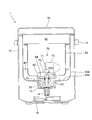
- 1 is a vertical sectional view of an automatic bread maker according to a first embodiment of the present invention.
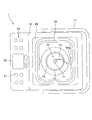
- 1 is a vertical sectional view of the automatic bread maker according to the first embodiment taken along a direction perpendicular to FIG.
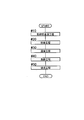
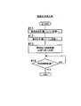
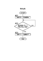
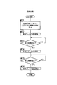
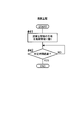
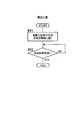
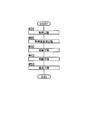
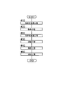
- Overall flowchart of the first aspect bread manufacturing process Flow chart of the impregnation step before crushing of the first aspect bread manufacturing process Flow chart of the grinding process of the first aspect bread manufacturing process Flow chart of the kneading process of the first aspect bread manufacturing process Flow chart of fermentation process of the first aspect bread manufacturing process Flow chart of baking process of first aspect bread manufacturing process
- Overall flowchart of the second aspect bread manufacturing process Flowchart of the impregnation step after crushing of the second aspect bread manufacturing step
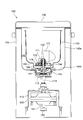
- Third aspect Bread production process overall flowchart Vertical sectional view of an automatic bread maker according to a
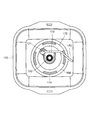
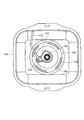
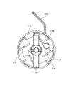
- Top view of the bread container during the kneading step in the automatic bread maker of the second embodiment The top view of the bread container at the time of the crushing process in the automatic bread maker of 2nd Embodiment
- mixing blade was equipped with.
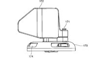
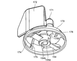
- Side view of a cover with a kneading blade provided in the automatic bread maker of the second embodiment The perspective view which looked at the cover which the automatic bread maker of 2nd Embodiment equipped with the kneading
- mixing blade was seen from the downward direction.
- FIG. 1 the left side of the drawing is the front (front) side of the automatic bread maker 1, and the right side of the drawing is the back (rear) side of the automatic bread maker 1. Further, it is assumed that the left hand side of the observer facing the automatic bread machine 1 from the front is the left side of the automatic bread machine 1, and the right hand side is the right side of the automatic bread machine 1.
- the automatic bread machine 1 has a box-shaped main body 10 composed of a synthetic resin outer shell.
- a handle 11 for transportation is attached to the upper part of the main body 10.
- An operation unit 20 is provided on the front surface of the main body 10.
- the operation unit 20 has operation keys such as a bread type selection key (flour bread, rice flour bread, bread with ingredients), cooking content selection key, timer key, start key, cancel key, and the like.
- a group of 21 and a display unit 22 for displaying set cooking contents, timer reservation time, and the like are provided.
- the display unit 22 is configured by a liquid crystal display panel.
- the upper surface of the main body behind the operation unit 20 is covered with a synthetic resin lid 30.
- the lid 30 is attached to an edge on the back side of the main body 10 with a hinge shaft (not shown), and rotates in a vertical plane with the hinge shaft as a fulcrum.
- a firing chamber 40 is provided inside the main body 10.
- the baking chamber 40 is made of sheet metal and has an open top surface, from which a bread container 50 is placed.
- the baking chamber 40 includes a peripheral side wall 40a and a bottom wall 40b having a rectangular horizontal section.
- a base 12 made of sheet metal is installed inside the main body 10.
- a bread container support 13 made of an aluminum alloy die-cast product is fixed at a location corresponding to the center of the firing chamber 40. The inside of the bread container support part 13 is exposed inside the baking chamber 40.
- a driving shaft 14 is vertically supported at the center of the bread container support 13.
- a pulley 15 is fixed to the lower end of the driving shaft 14.
- the pulley 15 is rotated by a motor 60 supported by the base 12.
- the motor 60 is a saddle shaft, and the output shaft 61 protrudes from the lower surface.
- a pulley 62 connected to the pulley 15 by a belt 63 is fixed to the output shaft 61.
- the bread container support unit 13 supports the bread container 50 by receiving a cylindrical pedestal 51 fixed to the bottom surface of the bread container 50.
- the pedestal 51 is also an aluminum alloy die cast product.
- the bread container 50 is made of sheet metal and has a bucket-like shape, and a handle (not shown) for handbags is attached to the mouth edge.
- the horizontal section of the bread container 50 is a rectangle with rounded corners.
- a blade rotation shaft 52 is vertically supported with a countermeasure against sealing. A rotational force is transmitted to the blade rotating shaft 52 from the driving shaft 14 through the coupling 53.
- the coupling 53 Of the two members constituting the coupling 53, one member is fixed to the lower end of the blade rotation shaft 52 and the other member is fixed to the upper end of the driving shaft 14. The entire coupling 53 is enclosed by the base 51 and the bread container support 13.
- a protrusion (not shown) is formed on the inner peripheral surface of the bread container support 13 and the outer peripheral surface of the pedestal 51, respectively.
- These protrusions constitute a well-known bayonet connection. That is, when the bread container 50 is attached to the bread container support part 13, the bread container 50 is lowered so that the protrusion of the base 51 does not interfere with the protrusion of the bread container support part 13. Then, after the pedestal 51 is fitted into the bread container support 13, when the bread container 50 is twisted horizontally, the protrusion of the pedestal 51 is engaged with the lower surface of the protrusion of the bread container support 13, and the bread container 50 is moved upward. It will not come out. By this operation, coupling 53 is also achieved at the same time.
- the twisting direction when the bread container 50 is attached coincides with the rotation direction of the kneading blade described later so that the bread container 50 does not come off even when the kneading blade rotates.
- the heating device 41 disposed inside the baking chamber 40 surrounds the bread container 50 and heats the bread-making material.
- the heating device 41 is constituted by a sheathed heater.
- the grinding blade 54 is attached to the blade rotation shaft 52 so as not to rotate.
- the crushing blade 54 is made of a stainless steel plate and has a shape like an airplane propeller.
- a flat circular recess 55 is formed at the bottom of the bread container 50, and the crushing blade 54 rotates inside the recess 55.
- the grinding blade 54 has a hub 54a at the center, and a groove (not shown) is formed on the lower surface of the hub 54a so as to cross the diametrical direction.
- a pin (not shown) penetrating the blade rotation shaft 52 horizontally receives the hub 54a and engages with the groove so that the hub 54a is non-rotatably coupled to the blade rotation shaft 52. Since the crushing blade 54 can be easily pulled out from the blade rotating shaft 52, it is possible to easily perform washing after the bread making operation and replacement when the sharpness is deteriorated.
- the kneading blade 70 is attached to the upper end of the blade rotation shaft 52.
- the kneading blade 70 is also an aluminum alloy die-cast product, and has a hub 71 fitted to the blade rotating shaft 52, a horizontal disk 72 provided under the hub 71, and a planar shape that rises perpendicularly to the upper surface of the disk 72. And a U-shaped blade 73.
- the disk 72 has a slightly smaller diameter than the recess 55 and substantially hides the recess 55.
- a one-way clutch (not shown) is interposed between the hub 71 of the kneading blade 70 and the blade rotation shaft 52.
- This one-way clutch connects the blade rotating shaft 52 and the kneading blade 70 when the blade rotating shaft 52 rotates counterclockwise in FIG. 3, and rotates the blade when the blade rotating shaft 52 rotates clockwise in FIG. The shaft 52 and the kneading blade 70 are disconnected.
- the hub 71 can be easily pulled out from the blade rotating shaft 52, the kneading blade 70 after the bread making operation can be easily washed.
- the operation control of the automatic bread maker 1 is performed by the control device 80 shown in FIG.
- the control device 80 is configured by a circuit board disposed at an appropriate location in the main body 10 (preferably a location that is not easily affected by the heat of the baking chamber 40).
- the motor driver 81 of the motor 60 is provided in addition to the operation unit 20 and the heating device 41.
- a temperature sensor 83 are connected.
- the temperature sensor 83 is disposed in the baking chamber 40 and detects the temperature of the baking chamber 40.
- 84 is a commercial power source for supplying power to each component.
- FIGS. 5 to 13 the first embodiment bread manufacturing process is shown in FIGS.
- FIG. 5 is an overall flowchart of the first aspect bread manufacturing process. As shown in FIG. 5, in the first aspect bread manufacturing process, the process proceeds in the order of pre-grinding impregnation process # 10, pulverization process # 20, kneading process # 30, fermentation process # 40, and baking process # 50. Then, the content of each process is demonstrated.
- step # 11 the user weighs the grain and puts a predetermined amount into the bread container 50.
- Rice grains are most easily available as grains, but other grains such as wheat, barley, straw, buckwheat, buckwheat, corn and the like can also be used.
- step # 12 the user measures the liquid and puts a predetermined amount into the bread container 50.
- a common liquid is water, but it may be a liquid having a taste component such as broth or fruit juice. Alcohol may be contained. Note that the order of step # 11 and step # 12 may be switched.
- the operation of putting the grains and liquid into the bread container 50 may be performed by taking the bread container 50 out of the baking chamber 40 or may be performed while the bread container 50 is put in the baking chamber 40.
- Step # 13 starts from this point.
- Step # 13 the mixture of cereal grains and liquid is allowed to stand in the bread container 50, and the cereal grains are impregnated with the liquid.
- the heating means 41 may be energized to increase the temperature of the baking chamber 40.
- step # 14 the control device 80 checks how much time has elapsed since the start of standing of the grain and liquid. When the predetermined time has elapsed, the pre-grinding impregnation step # 10 ends. This is notified to the user by display on the operation unit 20 or by voice.
- Step # 21 is started when the user inputs grinding operation data (type and amount of grain, type of bread to be baked, etc.) through the operation unit 20 and presses the start key.
- step # 21 the control device 80 drives the motor 60 and rotates the blade rotation shaft 52 in the clockwise direction in FIG. Then, the kneading blade 70 is disconnected from the blade rotation shaft 52 by the action of the one-way clutch, and no torque is applied to the kneading blade 70 from the blade rotation shaft 52, and only the grinding blade 54 rotates together with the blade rotation shaft 52. .
- the pulverization by the pulverization blade 54 is performed in a state where the liquid is immersed in the cereal grains, so that the cereal grains can be easily pulverized to the core. Since the pulverization is performed inside the recess 55, scattering of the grain is suppressed.
- step # 22 in order to obtain a desired pulverized grain, a pulverization pattern as set (however, when the pulverizing blade is continuously rotated, intermittently interlaced with a stop period, or intermittently rotated, the interval is taken.
- the control device 80 checks whether or not the rotation time length has been completed.
- step # 23 finish the rotation of the pulverization blade 54, and the pulverization step # 20 is completed. This is notified to the user by display on the display unit 22, voice, or the like.
- the pulverization step # 20 is started by the user's operation after the pre-grinding impregnation step # 10. If the pulverization operation data is input in the middle of No. 10, the pulverization step # 20 may be automatically started after the pre-pulverization impregnation step # 10 is completed.
- a kneading step # 30 shown in FIG. 8 is performed.
- the cereal grains and liquid in the bread container 50 are pasty or slurry dough raw materials.
- the material at the start of the kneading step # 30 is referred to as “dough raw material”, and the material that has come close to the intended state of the dough as the kneading progresses, ".
- step # 31 the user opens the lid 30 and puts a predetermined amount of gluten into the dough material. Add seasoning ingredients such as salt, sugar and shortening as needed.
- the automatic bread maker 1 may be provided with an automatic charging device for gluten and seasoning materials, and the user can input them without bothering the user.
- the user inputs the type of bread and cooking details from the operation unit 20 before and after Step # 31.
- the start key when the preparation is complete, the bread making operation that automatically continues from the kneading step # 30 to the fermentation step # 40 and further to the baking step # 50 is started.
- step # 32 the controller 80 drives the motor 60 to rotate the blade rotation shaft 52 counterclockwise in FIG. Then, the kneading blade 70 and the blade rotation shaft 52 are connected by the action of the one-way clutch, and the kneading blade 70 rotates together with the blade rotation shaft 52.
- the control device 80 energizes the heating device 41 and raises the temperature of the baking chamber 40.
- the dough raw material is kneaded and kneaded into a dough connected to one having a predetermined elasticity.
- an element of “kneading” is added to the kneading.
- the dough raw material in the recess 55 is gradually assimilated into the dough raw material kneaded by the kneading blade 70.
- step # 33 the controller 80 checks how much time has elapsed since the rotation of the kneading blade 70 started. When the predetermined time has elapsed, the process proceeds to step # 34.
- step # 34 the user opens the lid 30 and puts yeast into the dough.
- the yeast used in the dough may be dry yeast.
- Baking powder may be used instead of yeast.
- an automatic dosing device can be used to save the user.
- step # 35 the control device 80 checks how much time has passed since the yeast was added to the dough.
- the process proceeds to step # 36, where the rotation of the kneading blade 70 is completed.
- the dough that is connected and has the required elasticity has been completed. Since the disk 72 prevents the dough from entering the recess 55, most of the dough stays above the recess 55 and the amount entering the recess 55 is small.
- ingredients are introduced in any step of kneading step # 30.
- An automatic loading device can also be used for material loading.
- step # 41 the dough that has undergone the kneading step 30 is placed in a fermentation environment. That is, the control device 80 energizes the heating chamber 40 to the heating device 41 if necessary, and sets the temperature in a temperature zone where fermentation proceeds. The user arranges the dough, if necessary, and leaves the dough.
- step # 42 the control device 80 checks how much time has passed since the dough was placed in the fermentation environment. If predetermined time passes, fermentation process # 40 will be complete
- step # 50 the firing step # 50 shown in FIG. 10 is performed.
- step # 51 the fermented dough is placed in a baking environment. That is, the control device 80 sends electric power necessary for baking to the heating device 41 and raises the temperature of the baking chamber 40 to the baking temperature zone.
- step # 52 the control device 80 checks how much time has passed since the dough was placed in the baking environment.
- the firing step # 50 ends.
- the user since the completion of bread making is notified by display or sound on the display unit 22, the user opens the lid 30 and takes out the bread container 50. And bread is taken out from the bread container 50.
- the disc 72 prevents the dough from falling into the recess 55, so that no protrusion in the shape of the recess 55 is formed at the bottom of the pan.
- FIG. 11 is an overall flowchart of the second aspect bread manufacturing process.
- the process proceeds in the order of pulverization step # 20, post-pulverization impregnation step # 60, kneading step # 30, fermentation step # 40, and firing step # 50.
- the content of the post-grinding impregnation step # 60 will be described based on FIG.
- step # 61 the dough raw material formed in the pulverization step # 20 is allowed to stand inside the bread container 50. This dough raw material has not been subjected to the impregnation step before pulverization. While standing still, liquid soaks into the ground grain.
- the control device 80 energizes the heating device 41 as necessary to heat the dough material and promote the impregnation.
- step # 62 the control device 80 checks how much time has passed since the start of standing. When the predetermined time has elapsed, the post-grinding impregnation step # 60 is finished. When the post-grinding impregnation step # 60 is completed, the process automatically proceeds to the kneading step # 30.
- the steps after the kneading step # 30 are the same as the first aspect bread manufacturing step.
- FIG. 13 is an overall flowchart of the third aspect bread manufacturing process.
- the pre-pulverization impregnation step # 10 of the first aspect is placed before the pulverization step # 20
- the post-pulverization impregnation step 60 of the second aspect is placed after the pulverization step # 20.
- the processes after the kneading process 30 are the same as the first aspect bread manufacturing process.
- the crushing blade 54 can be used not only for crushing grains, but also for fragmenting ingredients such as nuts and leafy vegetables. For this reason, bread containing fine ingredients can be baked.
- the crushing blade 54 can also be used for crushing ingredients other than ingredients mixed in bread and crude drug ingredients.
- the rotation of the pulverizing blade 54 and the rotation of the kneading blade 70 can be controlled in association with each other by a single control device 80, the stage of pulverizing the cereal grains and the pulverized cereal flour At the stage of kneading, the rotation suitable for the type and amount of grain is given to the grinding blade 54 and the kneading blade 70, and the quality of the bread can be improved.
- the left side of the drawing is the front (front) side of the automatic bread maker 100
- the right side of the drawing is the back (rear) side of the automatic bread maker 100.
- the left hand side of the observer facing the automatic bread maker 100 from the front is the left side of the automatic bread maker 100
- the right hand side is the right side of the automatic bread maker 100.
- the automatic bread maker 100 has a box-shaped main body 110 constituted by an outer shell made of synthetic resin.
- An operation unit 120 is provided on the front surface of the main body 110.
- the operation unit 120 has operation keys such as a bread type selection key (wheat flour bread, rice flour bread, bread with ingredients), cooking content selection key, timer key, start key, cancel key, and the like.
- a display unit is provided for displaying the group and the set cooking contents and timer reservation time.
- the display unit includes a liquid crystal display panel and a display lamp using a light emitting diode as a light source.
- the upper surface of the main body behind the operation unit 120 is covered with a synthetic resin lid 130.
- the lid 130 is attached to an edge on the back side of the main body 110 with a hinge shaft (not shown), and rotates in a vertical plane with the hinge shaft as a fulcrum.
- a firing chamber 140 is provided inside the main body 110.
- the baking chamber 140 is made of sheet metal and has an open top surface from which a bread container 150 is placed.
- the baking chamber 140 includes a peripheral side wall 140a and a bottom wall 140b having a rectangular horizontal section.
- a base 112 made of sheet metal is installed inside the main body 110.
- a bread container support 113 made of an aluminum alloy die-cast product is fixed at a position corresponding to the center of the baking chamber 140. The inside of the bread container support 113 is exposed inside the baking chamber 140.
- a driving shaft 114 is vertically supported at the center of the bread container support portion 113.
- the pulleys 115 and 116 give rotation to the driving shaft 114.
- Clutchs are disposed between the pulley 115 and the driving shaft 114, and between the pulley 116 and the driving shaft 114, respectively, and when the pulley 115 is rotated in one direction to transmit the rotation to the driving shaft 114, the driving shaft 114 The rotation is not transmitted to the pulley 116, and when the pulley 116 is rotated in the opposite direction to the pulley 115 and the rotation is transmitted to the driving shaft 114, the rotation of the driving shaft 114 is not transmitted to the pulley 115.
- the pulley 115 is rotated by a kneading motor 160 supported by the base 112.
- the kneading motor 160 is a saddle shaft, and the output shaft 161 protrudes from the lower surface.
- a pulley 162 connected to the pulley 115 by a belt 163 is fixed to the output shaft 161.
- the kneading motor 160 itself is of a low speed / high torque type, and the pulley 162 further rotates the pulley 115 at a reduced speed, so that the driving shaft 114 rotates at a low speed / high torque.
- the crushing motor 164 supported by the base 112 that rotates the pulley 116.
- the grinding motor 164 is also a saddle shaft, and the output shaft 165 protrudes from the upper surface.
- a pulley 166 connected to the pulley 116 by a belt 167 is fixed to the output shaft 165.
- the grinding motor 164 plays a role of giving high speed rotation to the grinding blade described later. Therefore, a high-speed rotation type is selected as the grinding motor 164, and the reduction ratio between the pulley 166 and the pulley 116 is set to be approximately 1: 1.
- the bread container support unit 113 supports the bread container 150 by receiving a cylindrical pedestal 151 fixed to the bottom surface of the bread container 150.
- the pedestal 151 is also an aluminum alloy die cast product.
- the bread container 150 is made of sheet metal and has a bucket-like shape, and a handle for handbags (not shown) is attached to the mouth edge.
- the horizontal cross section of the bread container 150 is a rectangle with rounded corners.
- a vertical blade rotating shaft 152 is vertically supported at the center of the bottom of the bread container 150 with measures against sealing.
- a rotational force is transmitted to the blade rotating shaft 152 from the driving shaft 114 through the coupling 153.
- the coupling 153 Of the two members constituting the coupling 153, one member is fixed to the lower end of the blade rotating shaft 152, and the other member is fixed to the upper end of the driving shaft 114.
- the entire coupling 153 is enclosed by the base 151 and the bread container support 113.
- Protrusions are formed on the inner peripheral surface of the bread container support portion 113 and the outer peripheral surface of the base 151, respectively. These protrusions constitute a well-known bayonet connection. That is, when attaching the bread container 150 to the bread container support part 113, the bread container 150 is lowered so that the protrusion of the base 151 does not interfere with the protrusion of the bread container support part 113. Then, after the base 151 is fitted into the bread container support part 113, when the bread container 150 is twisted horizontally, the protrusion of the base 151 is engaged with the lower surface of the protrusion of the bread container support part 113, and the bread container 150 is moved upward. It will not come out.
- the heating device 141 disposed inside the baking chamber 140 surrounds the bread container 150 and heats the bread-making material.
- the heating device 141 includes a sheathed heater.
- the grinding blade 154 is attached to the blade rotating shaft 152 at a position slightly above the bottom of the bread container 150.
- the crushing blade 154 is not allowed to rotate with respect to the blade rotation shaft 152.
- the crushing blade 154 is made of a stainless steel plate and has a shape like an airplane propeller, as shown in FIGS.
- the central portion of the grinding blade 154 is a hub 154 a that is fitted to the blade rotation shaft 152.
- a groove 154b that crosses the hub 154a in the diametrical direction is formed on the lower surface of the hub 154a.
- a pin (not shown) penetrating the blade rotation shaft 152 horizontally receives the hub 154a and engages with the groove 154b to connect the grinding blade 154 to the blade rotation shaft 152 in a non-rotatable manner. Since the crushing blade 154 can be easily pulled out from the blade rotating shaft 152, it is possible to easily perform cleaning after the bread making operation and replacement when the sharpness deteriorates.
- a flat circular dome-shaped cover 170 is attached to the upper end of the blade rotation shaft 152.
- the cover 170 is made of an aluminum alloy die-cast product and covers the grinding blade 154.
- the cover 170 is rotatably fitted to the blade rotating shaft 152 and is received by the hub 154a of the grinding blade 154. Since the cover 170 can also be easily pulled out from the blade rotating shaft 152, cleaning after the bread making operation can be easily performed.
- the outer surface of the cover 170 is provided with a square-shaped kneading blade 172 by a vertical support shaft 171 disposed at a position away from the blade rotation shaft 152.
- the kneading blade 172 is also an aluminum alloy die cast product.
- the support shaft 171 is fixed to or integrated with the kneading blade 172 and moves together with the kneading blade 172.
- the kneading blade 172 rotates about the support shaft 171 with respect to the cover 170 in a horizontal plane, and takes two postures, a folded posture shown in FIG. 16 and an open posture shown in FIG.
- the kneading blade 172 In the folded position, the kneading blade 172 is in contact with a stopper portion 173 formed on the cover 170 and cannot be rotated clockwise with respect to the cover 70 any more. At this time, the tip of the kneading blade 172 slightly protrudes from the cover 170.
- the open position the kneading blade 172 is separated from the stopper portion 173, and the tip of the kneading blade 172 protrudes greatly from the cover 170.
- the cover 170 is formed with a window 174 that communicates the space inside the cover and the space outside the cover.
- the window 174 is disposed at a height that is aligned with the grinding blade 153 or higher.
- a total of four windows 174 are arranged at intervals of 90 °, but other numbers and arrangement intervals can be selected.
- a total of four ribs 175 are formed on the inner surface of the cover 170 corresponding to the windows 174.
- Each rib 175 extends obliquely from the vicinity of the center of the cover 170 to the outer peripheral annular wall with respect to the radial direction, and the four ribs 175 constitute a kind of bowl shape. Further, each rib 175 is curved so that the side facing the bread-making raw material pressing toward it is convex. The grinding blade 154 rotates so that the lower edge of the rib 175 is grazed.
- a clutch 176 (see FIG. 21) is interposed between the cover 170 and the blade rotating shaft 152.
- the clutch 176 connects the blade rotation shaft 152 and the cover 170 in the rotation direction of the blade rotation shaft 152 when the kneading motor 160 rotates the driving shaft 114 (rotation in this direction is referred to as “forward rotation”).
- the clutch 176 connects the blade rotation shaft 152 and the cover 170 in the rotation direction of the blade rotation shaft 152 when the crushing motor 164 rotates the driving shaft 114 (the rotation in this direction is referred to as “reverse rotation”). Is to be separated. 16 and 17, the “forward rotation” is a counterclockwise rotation, and the “reverse rotation” is a clockwise rotation.
- the clutch 176 includes a first engagement body 176a and a second engagement body 176b.
- the first engagement body 176 is fixed or integrally formed with the hub 154 a of the grinding blade 154, and is thus non-rotatably attached to the blade rotation shaft 152.
- the second engagement body 176b is fixed or integrally formed with the support shaft 171 of the kneading blade 172, and changes the angle according to the change in the posture of the kneading blade 172.
- the clutch 176 switches the connection state according to the attitude of the kneading blade 172. That is, when the kneading blade 172 is in the folded position shown in FIG. 16, the second engaging body 176b is at the angle shown in FIG. At this time, the second engagement body 176b interferes with the rotation path of the first engagement body 176a, and when the blade rotation shaft 152 rotates in the clockwise direction in FIG. The engaging body 176b is engaged, and the rotational force of the blade rotating shaft 152 is transmitted to the cover 170 and the kneading blade 172. When the kneading blade 172 is in the open position shown in FIG. 17, the second engaging body 176b has an angle shown in FIG.
- the second engagement body 176b is retracted from the rotation track of the first engagement body 176a, and even if the blade rotation shaft 152 rotates in the counterclockwise direction in FIG. And the second engagement body 176b is not engaged. Accordingly, the rotational force of the blade rotating shaft 152 is not transmitted to the cover 170 and the kneading blade 172.
- a recess 155 that accommodates the grinding blade 154 and the cover 170 is formed at the bottom of the bread container 150.
- the recess 155 is circular in a planar shape, and a gap 156 is formed between the outer periphery of the cover 170 and the inner surface of the recess 155 to allow the flow of the bread-making material.
- the operation control of the automatic bread maker 100 is performed by the control device 180 shown in FIG.
- the control device 180 is configured by a circuit board disposed at a suitable location in the main body 110 (preferably a location that is not easily affected by the heat of the baking chamber 140).
- a motor driver for the kneading motor 160 is provided in addition to the operation unit 120 and the heating device 141.
- 181, a motor driver 182 of the grinding motor 164, and a temperature sensor 183 are connected.
- the temperature sensor 183 is disposed in the baking chamber 140 and detects the temperature of the baking chamber 140.
- a commercial power source 184 supplies power to each component.
- Step # 21 is started when the user inputs grinding operation data (type and amount of grain, type of bread to be baked, etc.) through the operation unit 120 and presses the start key.
- step # 21 the control device 180 drives the grinding motor 164 to rotate the blade rotating shaft 152 in the reverse direction. Then, the grinding blade 154 starts rotating in the mixture of the grain and liquid.
- the cover 170 also follows the blade rotation shaft 152 and starts rotating. The rotation direction of the cover 170 at this time is clockwise in FIG. 16, and when the kneading blade 172 has been in the folded position until then, the kneading blade 172 turns to the open position by the resistance received from the mixture of the grain and liquid.
- the clutch 176 disconnects the connection between the blade rotation shaft 152 and the cover 170 by the second engagement body 176b retreating from the rotation locus of the first engagement body 176a.
- the kneading blade 170 in the open position hits the inner wall of the bread container 150 as shown in FIG. 17 and prevents the cover 170 from rotating.
- the blade rotation shaft 152 and the grinding blade 154 rotate at high speed in the opposite directions. Since the cover 170 and the kneading blade 172 are stopped, even if the grinding blade 154 rotates at a high speed, the mixture of grains and liquid does not vortex in the bread container 150. Therefore, the vortex swells at the periphery and does not spill out of the bread container 150.
- the grinding blade 154 rotates at high speed to grind the grain.
- the pulverization by the pulverization blade 154 is performed in a state where the liquid is soaked in the cereal grains, so that the cereal grains can be easily pulverized to the core.
- Ribs 175 extending from the vicinity of the center of the cover 170 to the outer peripheral annular wall suppress the flow of the mixture of the grain and the liquid in the same direction as the rotation direction of the grinding blade 154, and assist the grinding. That is, the ribs 175 act to change the flow of the mixture and increase the chance of collision with the grinding blade 154. Since the pulverization is performed in the cover 170, the grains are not scattered outside the bread container 150.
- the mixture of the pulverized grain and liquid is guided toward the window 174 by the rib 175, and is discharged out of the cover 170 through the window 174. Since the rib 175 is curved so that the side facing the mixture of the grain and liquid that presses toward it is convex, the mixture of the grain and liquid is less likely to stay on the surface of the rib 175, and the window 174 smoothly It flows toward.
- the mixture of the grain and liquid As the mixture of the grain and liquid is discharged from the inside of the cover 170, the mixture of the grain and liquid existing on the recess 155 enters the recess 155 through the gap 156, and enters the cover 170 from the recess 155. to go into. Grain grains in the cover 170 are pulverized by the pulverizing blade 154 and return to the top of the recess 155 from the window 174 of the cover 170.
- pulverizing while circulating a grain, a grain can be grind
- the window 174 is disposed at a height above the crushing blade 153 or above, the direction in which the mixture of the crushed grain and liquid is discharged from the cover 170 is horizontal or diagonally upward. Circulation is promoted.
- Step # 22 in order to obtain a desired pulverized grain, a pulverization pattern as set (however, when the pulverizing blade is continuously rotated, intermittently interlaced with a stop period, or intermittently rotated, the interval is taken.
- the control device 180 checks whether or not the rotation time length has been completed.
- the process proceeds to step # 23 to end the rotation of the pulverization blade 154, and the pulverization step # 20 is completed. This is notified to the user by display on the display unit 122, voice, or the like.
- a kneading step # 30 shown in FIG. 8 is performed.
- the cereal grains and liquid in the bread container 150 are pasty or slurry dough raw materials.
- step # 31 the user opens the lid 130 and puts a predetermined amount of gluten into the dough material. Add seasoning ingredients such as salt, sugar and shortening as needed.
- the automatic bread maker 100 may be provided with an automatic charging device for gluten and seasoning materials, and the user can input them without bothering the user.
- the user inputs the type of bread and cooking details from the operation unit 120 before and after Step # 31.
- the start key when the preparation is complete, the bread making operation that automatically continues from the kneading step # 30 to the fermentation step # 40 and further to the baking step # 50 is started.
- step # 32 the control device 180 drives the kneading motor 160.
- the kneading blade 172 changes from the open position to the folded position due to resistance from the dough material.
- the clutch 176 connects the blade rotation shaft 152 and the cover 170 when the second engagement body 176b has an angle that interferes with the rotation locus of the first engagement body 176a.
- the cover 170 and the kneading blade 172 It rotates in the positive direction together with the rotating shaft 152.
- the control device 180 energizes the heating device 141 and raises the temperature of the baking chamber 140.
- the kneading blade 172 rotates, the dough raw material is kneaded and kneaded into a dough connected to one having a predetermined elasticity.
- an element of “kneading” is added to the kneading.
- the rib 175 also rotates. By rotating the ribs 175, the dough material in the cover 170 is quickly discharged from the window 174 and assimilated into the dough material kneaded by the kneading blade 172.
- step # 33 the control device 180 checks how much time has elapsed since the start of the rotation of the kneading blade 172. When the predetermined time has elapsed, the process proceeds to step # 34.
- step # 34 the user opens the lid 130 and puts yeast into the dough.
- the yeast used in the dough may be dry yeast.
- Baking powder may be used instead of yeast.
- an automatic dosing device can be used to save the user.
- step # 35 the control device 180 checks how much time has passed since the yeast was added to the dough. When the time necessary to obtain the desired dough has elapsed, the process proceeds to step # 36, where the rotation of the kneading blade 172 is completed. At this point, the dough that is connected and has the required elasticity has been completed. Most of the dough stays above the recess 155 and only a small amount enters the recess 155.
- An automatic loading device can also be used for material loading.
- the fermentation process # 40 (see FIG. 9) and the baking process (see FIG. 10) are performed, and the bread is baked.
- the cover 170 is housed in the recess 155 and does not protrude from the bottom of the bread container 150. There is no such thing as leaving.
- the pulverizing blade 154 can be used not only for pulverizing grains but also for fragmenting ingredients such as nuts and leafy vegetables. . For this reason, bread containing fine ingredients can be baked.
- the crushing blade 154 can also be used for crushing ingredients other than ingredients mixed in bread and crude drug ingredients.
- the rotation of the grinding blade 154 and the rotation of the kneading blade 172 can be controlled in association with each other by a single control device 180, the stage of pulverizing the grain and the pulverized grain flour At the stage of kneading, the rotation suitable for the type and amount of grain is given to the grinding blade 154 and the kneading blade 172, and the quality of the bread can be improved.
- the present invention can be widely used for automatic bread machines mainly used in general households.
Landscapes
- Life Sciences & Earth Sciences (AREA)
- Engineering & Computer Science (AREA)
- Food Science & Technology (AREA)
- Food-Manufacturing Devices (AREA)
- Baking, Grill, Roasting (AREA)
Abstract
Description
本発明は上記の点に鑑みなされたものであり、穀物粒から直接パンを製造するのに便利な仕組みを備えた自動製パン機を提供し、パン製造をより身近なものにすることを目的とする。
まず、図1から図4を参照しながら第1実施形態の自動製パン機の構成について説明する。なお、図1において、図の左側が自動製パン機1の正面(前面)側、図の右側が自動製パン機1の背面(後面)側である。また、自動製パン機1に正面から向き合った観察者の左手側が自動製パン機1の左側、右手側が自動製パン機1の右側であるものとする。
次に、図14から図23を参照しながら第2実施形態の自動製パン機の構成について説明する。なお、図14において、図の左側が自動製パン機100の正面(前面)側、図の右側が自動製パン機100の背面(後面)側である。また、自動製パン機100に正面から向き合った観察者の左手側が自動製パン機100の左側、右手側が自動製パン機100の右側であるものとする。
設定通りの粉砕パターンが完遂されたらステップ#23に進んで粉砕ブレード154の回転を終了し、粉砕工程#20は終了する。このことは、表示部122における表示や、音声などで使用者に報知される。
以上、本発明が適用された第1実施形態及び第2実施形態の自動製パン機について説明したが、本発明の範囲はこれに限定されるものではなく、発明の主旨を逸脱しない範囲で種々の変更を加えて実施することができる。
10、110 本体
40、140 焼成室
50、150 パン容器
52、152 ブレード回転軸
54、154 粉砕ブレード
55、155 凹部
60 モータ
70、172 混練ブレード
72 ディスク
156 間隙
160 混練モータ
164 粉砕モータ
170 カバー
174 窓
176 クラッチ
Claims (8)
- 製パン原料を入れるパン容器と、
本体内に設けられ、前記パン容器を受け入れる焼成室と、
前記パン容器の底部に設けられるブレード回転軸と、
前記ブレード回転軸に装着される粉砕ブレードと、
前記粉砕ブレードより上側に配置される混練ブレードと、
前記ブレード回転軸に回転力を与えるモータと、
を備え、
前記パン容器の底部には前記ブレード回転軸を囲むように凹部が形成され、前記粉砕ブレードは前記凹部内で回転する、自動製パン機。 - 前記粉砕ブレードは、前記ブレード回転軸に回転不能に取り付けられ、
前記混練ブレードは、前記凹部より上で回転するように前記ブレード回転軸に装着され、
前記混練ブレードと前記ブレード回転軸との間には、両者を連結状態または非連結状態にするクラッチが介在する、請求項1に記載の自動製パン機。 - 前記クラッチは、前記ブレード回転軸が一方向に回転する時は前記混練ブレードと前記ブレード回転軸を連結状態にし、前記ブレード回転軸が前記一方向と逆方向に回転する時は前記混練ブレードと前記ブレード回転軸を非連結状態にする一方向クラッチである、請求項2に記載の自動製パン機。
- 前記凹部を隠すディスクが前記混練ブレードに組み合わせられている、請求項1から3のいずれかに記載の自動製パン機。
- 前記ブレード回転軸に装着され、前記粉砕ブレードを覆うとともに外面に前記混練ブレードを有するドーム状のカバーを更に備え、
前記カバーは前記凹部に収容される、請求項1に記載の自動製パン機。 - 前記粉砕ブレードは、前記ブレード回転軸に回転不能に取り付けられ、
前記カバーと前記ブレード回転軸との間には両者を連結状態または非連結状態にするクラッチが介在する、請求項5に記載の自動製パン機。 - 前記クラッチは、前記ブレード回転軸が一方向に回転する時は前記カバーと前記ブレード回転軸を連結状態にし、前記ブレード回転軸が前記一方向と逆方向に回転する時は前記カバーと前記ブレード回転軸を非連結状態にする、請求項6に記載の自動製パン機。
- 前記カバー外周部と前記凹部内面との間には製パン原料の流動を可能とする間隙が形成され、
前記カバーにはカバー内空間とカバー外空間を連通させる窓が形成されている、請求項5から7のいずれかに記載の自動製パン機。
Priority Applications (2)
| Application Number | Priority Date | Filing Date | Title |
|---|---|---|---|
| CN201080037809.1A CN102665507B (zh) | 2009-08-25 | 2010-08-24 | 自动制面包机 |
| US13/388,614 US20120125208A1 (en) | 2009-08-25 | 2010-08-24 | Automatic bread-maker |
Applications Claiming Priority (4)
| Application Number | Priority Date | Filing Date | Title |
|---|---|---|---|
| JP2009-194122 | 2009-08-25 | ||
| JP2009194125A JP5295040B2 (ja) | 2009-08-25 | 2009-08-25 | 自動製パン機 |
| JP2009194122A JP5295039B2 (ja) | 2009-08-25 | 2009-08-25 | 自動製パン機 |
| JP2009-194125 | 2009-08-25 |
Publications (1)
| Publication Number | Publication Date |
|---|---|
| WO2011024776A1 true WO2011024776A1 (ja) | 2011-03-03 |
Family
ID=43627881
Family Applications (1)
| Application Number | Title | Priority Date | Filing Date |
|---|---|---|---|
| PCT/JP2010/064219 Ceased WO2011024776A1 (ja) | 2009-08-25 | 2010-08-24 | 自動製パン機 |
Country Status (4)
| Country | Link |
|---|---|
| US (1) | US20120125208A1 (ja) |
| CN (1) | CN102665507B (ja) |
| TW (1) | TWI391096B (ja) |
| WO (1) | WO2011024776A1 (ja) |
Cited By (1)
| Publication number | Priority date | Publication date | Assignee | Title |
|---|---|---|---|---|
| JP2014050448A (ja) * | 2012-09-05 | 2014-03-20 | Panasonic Corp | 自動製パン機 |
Families Citing this family (5)
| Publication number | Priority date | Publication date | Assignee | Title |
|---|---|---|---|---|
| CN103767560B (zh) * | 2012-10-24 | 2017-04-12 | 松下电器产业株式会社 | 自动制面包机 |
| CN104869877B (zh) * | 2012-12-20 | 2017-12-01 | 松下知识产权经营株式会社 | 自动制面包机 |
| CN103229942B (zh) * | 2013-05-14 | 2014-04-02 | 李洪剑 | 一种家用馒头和面成型机 |
| US20190069558A1 (en) * | 2016-03-14 | 2019-03-07 | Panasonic Intellectual Property Management Co., Ltd. | Automatic bread maker |
| USD1129177S1 (en) * | 2023-12-27 | 2026-06-09 | Jiangmen Kangbaishi Electrical Appliances Co., Ltd | Bread maker |
Citations (4)
| Publication number | Priority date | Publication date | Assignee | Title |
|---|---|---|---|---|
| JPS63153023A (ja) * | 1986-12-18 | 1988-06-25 | 松下電器産業株式会社 | 電気製パン機 |
| JPH09224842A (ja) * | 1996-02-28 | 1997-09-02 | Matsushita Electric Ind Co Ltd | 自動製パン機 |
| JP2000116526A (ja) * | 1998-10-13 | 2000-04-25 | Matsushita Electric Ind Co Ltd | 自動製パン機 |
| JP3191645B2 (ja) * | 1995-10-27 | 2001-07-23 | 松下電器産業株式会社 | 自動製パン機 |
Family Cites Families (12)
| Publication number | Priority date | Publication date | Assignee | Title |
|---|---|---|---|---|
| US5074201A (en) * | 1989-05-12 | 1991-12-24 | Matsushita Electric Industrial Co., Ltd. | Apparatus for manufacturing tonyu and tofu |
| US5005364A (en) * | 1990-02-07 | 1991-04-09 | Nelson William R | Apparatus for and method of making and delivering slush ice |
| JP3255205B2 (ja) * | 1993-12-06 | 2002-02-12 | 船井電機株式会社 | 製パン機 |
| CN1094745C (zh) * | 1994-11-14 | 2002-11-27 | 松下电器产业株式会社 | 自动面包机 |
| US5921169A (en) * | 1997-01-03 | 1999-07-13 | China Pacific Trade Ltd. | Automatic baking apparatus |
| JPH1176068A (ja) * | 1997-08-07 | 1999-03-23 | Mk Seiko Co Ltd | 製パン機 |
| JP2000037304A (ja) * | 1998-07-21 | 2000-02-08 | Mk Seiko Co Ltd | 製パン機 |
| TW432926U (en) * | 2000-07-21 | 2001-05-01 | Huang Shiue Fen | Ice-cream blender |
| JP4609377B2 (ja) * | 2006-05-17 | 2011-01-12 | パナソニック株式会社 | 自動製パン機 |
| US7780337B2 (en) * | 2007-02-19 | 2010-08-24 | Zheng Peng | Blend soup maker |
| CN101427696A (zh) * | 2007-11-10 | 2009-05-13 | 威斯达电器(中山)制造有限公司 | 一种新型面包机 |
| JP2009125516A (ja) * | 2007-11-28 | 2009-06-11 | Sanyo Electric Co Ltd | 自動製パン器 |
-
2010
- 2010-08-24 US US13/388,614 patent/US20120125208A1/en not_active Abandoned
- 2010-08-24 WO PCT/JP2010/064219 patent/WO2011024776A1/ja not_active Ceased
- 2010-08-24 CN CN201080037809.1A patent/CN102665507B/zh active Active
- 2010-08-25 TW TW099128391A patent/TWI391096B/zh not_active IP Right Cessation
Patent Citations (4)
| Publication number | Priority date | Publication date | Assignee | Title |
|---|---|---|---|---|
| JPS63153023A (ja) * | 1986-12-18 | 1988-06-25 | 松下電器産業株式会社 | 電気製パン機 |
| JP3191645B2 (ja) * | 1995-10-27 | 2001-07-23 | 松下電器産業株式会社 | 自動製パン機 |
| JPH09224842A (ja) * | 1996-02-28 | 1997-09-02 | Matsushita Electric Ind Co Ltd | 自動製パン機 |
| JP2000116526A (ja) * | 1998-10-13 | 2000-04-25 | Matsushita Electric Ind Co Ltd | 自動製パン機 |
Cited By (1)
| Publication number | Priority date | Publication date | Assignee | Title |
|---|---|---|---|---|
| JP2014050448A (ja) * | 2012-09-05 | 2014-03-20 | Panasonic Corp | 自動製パン機 |
Also Published As
| Publication number | Publication date |
|---|---|
| US20120125208A1 (en) | 2012-05-24 |
| CN102665507A (zh) | 2012-09-12 |
| TW201112963A (en) | 2011-04-16 |
| CN102665507B (zh) | 2014-10-22 |
| TWI391096B (zh) | 2013-04-01 |
Similar Documents
| Publication | Publication Date | Title |
|---|---|---|
| WO2011024778A1 (ja) | 自動製パン機 | |
| JP5449795B2 (ja) | 自動製パン機 | |
| WO2011024779A1 (ja) | 自動製パン機 | |
| CN102665507B (zh) | 自动制面包机 | |
| WO2011024589A1 (ja) | 自動製パン器 | |
| JP5295040B2 (ja) | 自動製パン機 | |
| JP5289245B2 (ja) | 自動製パン機 | |
| JP5295039B2 (ja) | 自動製パン機 | |
| US20120240788A1 (en) | Automatic bread maker | |
| JP2011120689A (ja) | 自動製パン機 | |
| JP5845444B2 (ja) | 自動製パン機 | |
| JP5295041B2 (ja) | 自動製パン機 | |
| JP4859965B2 (ja) | 自動製パン機 | |
| JP4859966B2 (ja) | 自動製パン機 | |
| JP2011120690A (ja) | 自動製パン機 | |
| JP2010184081A (ja) | 自動製パン機 | |
| JP5682695B2 (ja) | 自動製パン機 | |
| TWI406646B (zh) | 自動製麵包機 | |
| JP2011152271A (ja) | 自動製パン機 | |
| JP5402676B2 (ja) | 自動製パン機 | |
| JP5402577B2 (ja) | 自動製パン器 | |
| JP2010184082A (ja) | 自動製パン機 | |
| JP2012147994A (ja) | 自動製パン器 | |
| JP2010246590A (ja) | 自動製パン機 | |
| WO2011129004A1 (ja) | 自動製パン機 |
Legal Events
| Date | Code | Title | Description |
|---|---|---|---|
| WWE | Wipo information: entry into national phase |
Ref document number: 201080037809.1 Country of ref document: CN |
|
| 121 | Ep: the epo has been informed by wipo that ep was designated in this application |
Ref document number: 10811826 Country of ref document: EP Kind code of ref document: A1 |
|
| WWE | Wipo information: entry into national phase |
Ref document number: 13388614 Country of ref document: US |
|
| NENP | Non-entry into the national phase |
Ref country code: DE |
|
| 122 | Ep: pct application non-entry in european phase |
Ref document number: 10811826 Country of ref document: EP Kind code of ref document: A1 |