WO2011010553A1 - 車両用ドアロック装置 - Google Patents
車両用ドアロック装置 Download PDFInfo
- Publication number
- WO2011010553A1 WO2011010553A1 PCT/JP2010/061498 JP2010061498W WO2011010553A1 WO 2011010553 A1 WO2011010553 A1 WO 2011010553A1 JP 2010061498 W JP2010061498 W JP 2010061498W WO 2011010553 A1 WO2011010553 A1 WO 2011010553A1
- Authority
- WO
- WIPO (PCT)
- Prior art keywords
- lever
- key
- lock device
- door lock
- vehicle door
- Prior art date
Links
Images


Classifications
-
- E—FIXED CONSTRUCTIONS
- E05—LOCKS; KEYS; WINDOW OR DOOR FITTINGS; SAFES
- E05B—LOCKS; ACCESSORIES THEREFOR; HANDCUFFS
- E05B17/00—Accessories in connection with locks
- E05B17/04—Devices for coupling the turning cylinder of a single or a double cylinder lock with the bolt operating member
- E05B17/041—Coupling device with a shaft projecting axially rearwardly from the cylinder, e.g. affording a degree of universal motion to compensate for misalignment
-
- E—FIXED CONSTRUCTIONS
- E05—LOCKS; KEYS; WINDOW OR DOOR FITTINGS; SAFES
- E05B—LOCKS; ACCESSORIES THEREFOR; HANDCUFFS
- E05B81/00—Power-actuated vehicle locks
- E05B81/12—Power-actuated vehicle locks characterised by the function or purpose of the powered actuators
- E05B81/16—Power-actuated vehicle locks characterised by the function or purpose of the powered actuators operating on locking elements for locking or unlocking action
-
- E—FIXED CONSTRUCTIONS
- E05—LOCKS; KEYS; WINDOW OR DOOR FITTINGS; SAFES
- E05B—LOCKS; ACCESSORIES THEREFOR; HANDCUFFS
- E05B81/00—Power-actuated vehicle locks
- E05B81/24—Power-actuated vehicle locks characterised by constructional features of the actuator or the power transmission
- E05B81/32—Details of the actuator transmission
- E05B81/34—Details of the actuator transmission of geared transmissions
- E05B81/36—Geared sectors, e.g. fan-shaped gears
-
- E—FIXED CONSTRUCTIONS
- E05—LOCKS; KEYS; WINDOW OR DOOR FITTINGS; SAFES
- E05B—LOCKS; ACCESSORIES THEREFOR; HANDCUFFS
- E05B83/00—Vehicle locks specially adapted for particular types of wing or vehicle
- E05B83/36—Locks for passenger or like doors
-
- E—FIXED CONSTRUCTIONS
- E05—LOCKS; KEYS; WINDOW OR DOOR FITTINGS; SAFES
- E05B—LOCKS; ACCESSORIES THEREFOR; HANDCUFFS
- E05B85/00—Details of vehicle locks not provided for in groups E05B77/00 - E05B83/00
- E05B85/06—Lock cylinder arrangements
-
- E—FIXED CONSTRUCTIONS
- E05—LOCKS; KEYS; WINDOW OR DOOR FITTINGS; SAFES
- E05B—LOCKS; ACCESSORIES THEREFOR; HANDCUFFS
- E05B81/00—Power-actuated vehicle locks
- E05B81/02—Power-actuated vehicle locks characterised by the type of actuators used
- E05B81/04—Electrical
- E05B81/06—Electrical using rotary motors
-
- Y—GENERAL TAGGING OF NEW TECHNOLOGICAL DEVELOPMENTS; GENERAL TAGGING OF CROSS-SECTIONAL TECHNOLOGIES SPANNING OVER SEVERAL SECTIONS OF THE IPC; TECHNICAL SUBJECTS COVERED BY FORMER USPC CROSS-REFERENCE ART COLLECTIONS [XRACs] AND DIGESTS
- Y10—TECHNICAL SUBJECTS COVERED BY FORMER USPC
- Y10T—TECHNICAL SUBJECTS COVERED BY FORMER US CLASSIFICATION
- Y10T70/00—Locks
- Y10T70/50—Special application
- Y10T70/5093—For closures
- Y10T70/5155—Door
-
- Y—GENERAL TAGGING OF NEW TECHNOLOGICAL DEVELOPMENTS; GENERAL TAGGING OF CROSS-SECTIONAL TECHNOLOGIES SPANNING OVER SEVERAL SECTIONS OF THE IPC; TECHNICAL SUBJECTS COVERED BY FORMER USPC CROSS-REFERENCE ART COLLECTIONS [XRACs] AND DIGESTS
- Y10—TECHNICAL SUBJECTS COVERED BY FORMER USPC
- Y10T—TECHNICAL SUBJECTS COVERED BY FORMER US CLASSIFICATION
- Y10T70/00—Locks
- Y10T70/50—Special application
- Y10T70/5889—For automotive vehicles
- Y10T70/5956—Steering mechanism with switch
Definitions
- the present invention relates to a vehicle door lock device.
- a lock is connected to a key cylinder disposed on an outside handle of the vehicle door via a rod, and a lock operation / unlock operation (locking) is performed according to the rotation operation of the key cylinder.
- a mechanism provided with a lever mechanism for performing (unlocking) for example, shown in Japanese Patent No. 3777968 (JP3777968B).
- JP3777968B Japanese Patent No. 3777968
- the lever mechanism is inserted into the inner end portion 9a of the rod 9 in the vehicle width direction as shown in FIGS.
- a key rotor 1 having a connecting hole portion 1a that is connected so as to be able to transmit torque and is rotatably assembled to the housing 2, and is rotatably supported by the housing 2 and the key rotor 1 and torque is applied to the key rotor 1.
- a key lever 3 having a hub portion 3a connected so as to be able to be transmitted and disposed in the housing 2, and an idle lever 4 rotatably assembled to a support shaft 3a1 provided on the hub portion 3a of the key lever 3 It has.
- the idle lever 4 includes a round hole 4a that is rotatably fitted to the support shaft 3a1, an arc-shaped elongated hole 4b that can accommodate a protrusion 3a2 provided on the hub portion 3a, and that is centered on the round hole 4a.
- the housing 2 has a U-shaped claw portion 4c that holds the protrusion 5a of the active lever 5 rotatably mounted. For this reason, when the active lever 5 is in the unlocked state and the key cylinder is rotated in the locking direction by the key from the initial state (the state in which the key can be inserted into and removed from the key cylinder), the rod 9 is interposed through the rod 9.
- the key lever 3 rotates in the locking direction integrally with the key rotor 1.
- the projection 3a2 of the key lever 3 is idled by a predetermined amount in the arc-shaped elongated hole 4b of the idle lever 4, and then is engaged with one end wall of the arc-shaped elongated hole 4b, so that the key lever 3 and the idle lever 4 rotates integrally in the locking direction.
- the protrusion 5a of the active lever 5 is pushed in the locking direction by the U-shaped claw portion 4c of the idle lever 4, and the active lever 5 is rotated in the locking direction.
- the key rotor 1 is rotated in the unlocking direction via the rod 9. Then, the key lever 3 rotates integrally with the key rotor 1 in the unlocking direction. At this time, the protrusion 3a2 of the key lever 3 idles a predetermined amount in the arc-shaped elongated hole 4b of the idle lever 4, and then engages with the other end wall of the arc-shaped elongated hole 4b, so that the key lever 3 and the idle lever 4 integrally rotates in the unlocking direction.
- the protrusion 5a of the active lever 5 is pushed in the unlocking direction by the U-shaped claw portion 4c of the idle lever 4, and the active lever 5 is rotated in the unlocking direction.
- a lock / unlock member (open link) interposed in an open mechanism that operates to open the vehicle door to a vehicle body is locked. Since the operation of the open mechanism is restricted by being held at the (lock position), even if the outside handle is opened, the open mechanism does not operate and the vehicle door opens to the vehicle body. Not.
- the lock / unlock member (open link) is held in the unlocked position (unlocked position), and the operation of the open mechanism is allowed.
- the opening mechanism is activated and the vehicle door is opened with respect to the vehicle body.
- the lever mechanism includes the three components of the key rotor 1, the key lever 3, and the idle lever 4 as shown in FIGS. Therefore, it is desired to reduce the number of parts.
- the present invention has been made to solve the above-described problems.
- the vehicle door lock device according to the present invention is adapted to be linked to a key cylinder disposed on the outside handle of the vehicle door via a rod, and is locked / unlocked according to the turning operation of the key cylinder.
- the lever mechanism includes a key rotor that has a connecting hole portion in which an inner end portion of the rod is inserted in the vehicle width direction and is connected so as to be able to transmit torque, and is rotatably assembled to the housing, and the housing and the key rotor
- a key lever disposed in the housing having a hub portion rotatably supported by the key rotor and coupled to the key rotor so as to transmit torque;
- the key lever extends radially outward from the hub portion, and is engaged with a first engagement portion of an active lever that is rotatably assembled in the housing, and a diameter from the hub portion.
- a second arm portion extending outwardly and engageable with a second engagement portion of the active lever;
- the active lever When the active lever is in the unlocked state and the key cylinder is rotated in the locking direction from the initial state, the first arm portion of the active lever is idled after a predetermined amount of idling of the first arm portion of the key lever. Engaging with the engaging portion, the active lever is rotated in the locking direction, and When the active lever is in a locked state and the key cylinder is rotated in the unlocking direction from the initial state, the second arm portion of the key lever is idled by a predetermined amount after the second arm portion of the key lever is idled.
- the active lever is set so as to rotate in the unlocking direction by engaging with the engaging portion.
- the operation when the cylinder is turned in the unlocking direction from the initial state is substantially the same as each operation obtained in the above-described conventional vehicle door lock device.
- the lever mechanism that performs the locking / unlocking operation according to the turning operation of the key cylinder includes the key rotor and the key lever, but does not include the idle lever. For this reason, an idle lever is unnecessary in the lever mechanism, and the lever mechanism of the door lock device can be configured simply and inexpensively.
- the first arm portion and the second arm portion are provided to be displaced in the rotational axis direction of the key lever, and the first arm portion is engaged with the second engagement portion.
- the second arm portion may not be engaged with the first engaging portion.
- the second arm portion and the first engagement portion are arranged in the direction of the rotation axis. Can be placed on top of each other.
- the first arm portion and the second engagement portion are arranged so as to overlap in the rotational axis direction in the locked state. can do.
- the first arm portion and the second arm portion can be brought close to each other, and the key lever can be prevented from being enlarged.
- a fragile portion that can be damaged when the rod is pushed toward the key lever with a force greater than a set value. It is also possible. In this case, when the rod is pushed toward the key lever with a force greater than the set value, the key lever is damaged at the weak part. For this reason, in such a state, in the key lever, rotation is not transmitted from the hub portion to the second arm portion, and even if the key rotor is rotated in the unlocking direction, the active lever is not rotated in the unlocking direction.
- the housing is provided with a breakage assisting portion that assists the breakage of the key lever at the fragile portion when the rod is pushed toward the key lever with a force greater than a set value. It is also possible. In this case, as compared with the case where the housing is not provided with a breakage assisting part, when the rod is pushed toward the key lever with a force greater than the set value, the breakage at the weak part of the key lever should be ensured. It is possible to further enhance the anti-theft function of the door lock device.
- the breakage assisting portion includes an arc-shaped rib extending in an arc shape centering on a circular portion that rotatably supports the key lever, and a linear rib extending on the inner peripheral side of the arc-shaped rib. It is also possible. In this case, the linear rib extends from the circular portion toward an intermediate portion of the arc-shaped rib, and the linear rib and the arc-shaped rib may be slightly separated from each other.
- the key rotor and the key lever can be coaxially arranged and integrated.
- the lever mechanism can be configured with a single component, and the lever mechanism of the door lock device can be configured more simply and inexpensively.
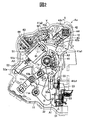
- FIG. 1 is a rear view of an embodiment of a vehicle door lock device according to the present invention, which is disposed inside a door and is viewed from the rear side of the door.
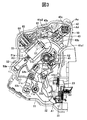
- FIG. 2 is a side view of the main configuration of the vehicle door lock device shown in FIG.
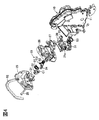
- FIG. 3 is a side view of the main configuration of the vehicle door lock device shown in FIG.
- FIG. 4 is an exploded perspective view of a part of the open mechanism and the latch mechanism in the vehicle door lock device shown in FIGS.
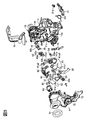
- FIG. 5 is an exploded perspective view of an open mechanism, a lock mechanism, an electric actuator, and the like in the vehicle door lock device shown in FIGS. 6 is a cross-sectional view taken along the line XX of FIG.
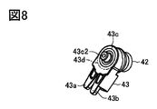
- FIG. 8 is a perspective view of a state in which the key rotor and the key lever shown in FIG. 5 are combined.
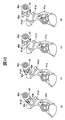
- FIG. 9 is an operation explanatory diagram when the main lever of the active lever shown in FIGS. 2, 3 and 5 is rotated from the unlocked state to the locked state by the key lever.
- FIG. 10 is an operation explanatory view when the main lever of the active lever shown in FIGS. 2, 3 and 5 is rotated from the locked state to the unlocked state by the key lever.
- FIG. 10 is an operation explanatory view when the main lever of the active lever shown in FIGS. 2, 3 and 5 is rotated from the locked state to the unlocked state by the key lever.
- FIG. 11 is a side view of a portion of the housing shown in FIGS. 5 to 7 that accommodates the key lever of the housing cover as viewed from the inside of the housing.
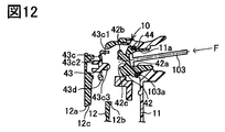
- FIG. 12 is a cross-sectional view when the key lever and the housing cover in the housing are damaged due to the external force in the rod axis direction acting on the key rotor shown in FIG.
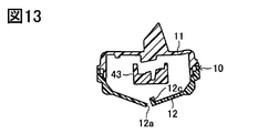
- FIG. 13 is a cross-sectional view of a portion corresponding to FIG. 7 when the housing cover in the housing is damaged as shown in FIG.
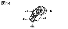
- FIG. 14 is a perspective view showing the relationship between the key rotor and the key lever when the key lever is broken as shown in FIG.
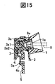
- FIG. 15 is a cross-sectional view of a portion corresponding to FIG. 6 in a conventional vehicle door lock device.
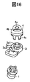
- 16 is an exploded perspective view of a key rotor, a key lever, and an idle lever in the conventional vehicle door lock device shown in FIG.
- FIG. 1 to 5 show a vehicle door lock device Ao according to the present invention.
- This vehicle door lock device Ao is attached to a door FD provided on the front right side of the vehicle.
- an open mechanism A1, a lock mechanism A2, and an electric actuator A3 are provided, and a housing 10 that houses the open mechanism A1, the lock mechanism A2, and the electric actuator A3 is provided.
- the housing 10 includes a housing body 11, a housing cover 12 that is assembled to the housing body 11, and a protector 13 that is assembled to the housing body 11 and the housing cover 12 ( (See FIG. 5).
- a seal ring 91 is assembled between the housing cover 12 and the inner plate of the door FD.
- the open mechanism A1 is for operating the known latch mechanism 20 (see FIGS. 1 and 4) from the latched state to the unlatched state so that the door FD of the vehicle can be opened with respect to the vehicle body (vehicle body).
- the latch mechanism 20 is for holding the door FD in a closed state (a state in which the door FD is closed) with respect to the vehicle body, and a latch 21 that can be engaged with and disengaged from a striker (not shown) fixed to the vehicle body. It has.
- the latch mechanism 20 is not shown in FIGS. 2 and 3, but is shown in a disassembled state in FIG. 4, and is assembled to the door FD in a state assembled to the housing 10. (See FIG. 1).
- the latch mechanism 20 is engaged with the striker to hold the door FD in a closed state (latch state). In the closed state of the door FD, the latch mechanism 20 moves away from the striker to shift the door FD from the closed state to an open state (a state in which the door can be opened with respect to the vehicle body) (an unlatched state).
- the latch mechanism 20 includes a latch 21, a pawl 22, a lift lever 23, and a stopper 24, and includes cushions C1 and C2, a latching torsion spring S1, and a pawl torsion spring S2. These components are assembled to the base plate 25, the case 26, and the sub base plate 27 using screws 28 and pins 29.
- the base plate 25 is assembled to the door FD via a seal member 92 (not shown in FIG. 1) shown in FIG.
- the open mechanism A1 includes an outside open lever 31, an inside open lever 32, and an open link 33 (lock / unlock member).
- the outside open lever 31 is assembled to the housing body 11 together with the torsion spring S3, and is linked to the outside handle 101 (see FIG. 1) provided outside the door FD via the link mechanism L1, The pulling operation of the outside handle 101 rotates the clockwise direction in FIG.
- the outside open lever 31 is assembled with a clip 31a (see FIGS. 1, 4 and 5).
- the inside open lever 32 is rotatably assembled to a support shaft 11a provided on the housing body 11, and is linked to an inside handle (not shown) provided on the indoor side of the door FD, so that the inside handle can be pulled. As a result, it rotates in the counterclockwise direction of FIGS.
- the open link 33 is slidably connected to the outside open lever 31 at the lower end portion thereof, and the active lever 41, which is a component of the lock mechanism A2, is connected to the unlock position shown in FIG. 2 and FIG. It can swing between the lock position shown. 2, the open link 33 can be engaged with the lift lever 23 of the latch mechanism 20 to open the door FD, and in the locked position shown in FIG. The latch mechanism 20 cannot be engaged with the lift lever 23.
- the open link 33 receives the operation of the outside open lever 31 (pulling operation of the outside handle 101) or the operation of the inside open lever 32 (pulling operation of the inside handle), and FIG. 3 is moved upward from the position shown in FIG. 3 (upward in FIGS. 2 and 3). Therefore, when the door FD is in the closed state, the open link 33 is in the unlocked position shown in FIG. 2 and is moved upward in response to the operation of the outside open lever 31 or the inside open lever 32.
- the lift lever 23 of the mechanism 20 is pushed and rotated by the open link 33, and the latch mechanism 20 operates from the latched state to the unlatched state. Thereby, the door FD shifts from the closed state to the open state. That is, when the open link 33 is in the unlock position in FIG.
- the door FD is unlocked.
- the open link 33 is in the locked position shown in FIG. 3 and is moved upward in response to the operation of the outside open lever 31 or the inside open lever 32 in the closed state of the door FD, the open link 33. Is not engaged with the lift lever 23 of the latch mechanism 20, and the latch mechanism 20 is held in the latched state. As a result, the door FD is held in the closed state. That is, when the open link 33 is in the lock position of FIG. 3, the door FD is locked.
- the lock mechanism A2 controls or allows the operation of the open mechanism A1 to lock or unlock the door FD, and includes the above-described active lever 41 and the above-described open link 33 via the active lever 41.
- the lever mechanism A4 for driving to a locked position or unlocked position.
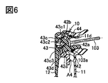
- the lever mechanism A4 includes a key rotor (sometimes called a key-outside locking lever) 42 and a key lever (sometimes called a key switch lever) 43, as shown in FIGS.
- the key rotor 42 is connected to the key cylinder 102 disposed on the outside handle 101 via the rod 103.
- the lever mechanism A4 performs a locking operation (an operation for moving the open link 33 from the unlock position to the lock position via the active lever 41) in response to the rotation operation of the key cylinder 102 (mechanical key operation by the key).
- an unlocking operation (an operation of moving the open link 33 from the locked position to the unlocked position via the active lever 41) can be performed.
- the active lever 41 is assembled to a support shaft 11b provided in the housing body 11 together with a torsion spring S4 (see FIG. 5), and is rotatably supported by the support shaft 11b.
- the active lever 41 includes a main lever 41a, a sub lever 41b, and a torsion spring 41c.
- the main lever 41a is rotatably assembled to the support shaft 11b, and includes a first engagement portion 41a1 that is engageable with the first arm portion 43a of the key lever 43, and a second arm portion 43b of the key lever 43.
- the sub lever 41b is rotatably attached to the support shaft 11b, can rotate relative to the main lever 41a by a predetermined amount, and has an engaging portion (pin portion) 41b1 linked to the long hole 33a of the open link 33.
- the torsion spring 41c biasing member
- the sub lever 41b is urged to rotate in one direction (the counterclockwise direction shown in FIGS. 2 and 3).
- the key rotor 42 has a non-circular coupling hole 42 a into which the inner end 103 a of the rod 103 is inserted in the vehicle width direction and coupled so as to be able to transmit torque.
- a through hole 11d provided in the housing body 11 is rotatably assembled via a seal ring 44.
- the key rotor 42 has a connecting projection 42b that is connected to a non-circular connecting hole 43c1 provided in the hub 43c of the key lever 43 so that torque can be transmitted.
- the key lever 43 has a hub portion 43 c that is coupled to the key rotor 42 so as to be able to transmit torque, and extends radially outward from the hub portion 43 c so that the main lever 43 in the active lever 41 A first arm portion 43a engageable with the first engaging portion 41a1 of the lever 41a, and a second arm portion extending radially outward from the hub portion 43c and engageable with the second engaging portion 41a2 of the main lever 41a 43b.
- the first arm portion 43a and the first engagement portion 41a1 are provided by being displaced by a predetermined amount on the vehicle outer side (housing body 11 side) with respect to the second arm portion 43b and the second engagement portion 41a2 (that is, The first arm portion 43a and the second arm portion 43b, and the first engaging portion 41a1 and the second engaging portion 41a2 are provided with a predetermined amount of displacement in the direction of the rotational axis of the key lever 43, respectively)
- the first arm portion 43a is not engaged with the second engagement portion 41a2 (see FIGS. 10A and 10B), and the second arm portion 43b is the first engagement portion.
- the key lever 43 is rotatably supported by the housing cover 12 of the housing 10 by a shaft portion 43c2 provided in the hub portion 43c, and the key rotor by a projection portion 43c3 provided in the hub portion 43c. It is rotatably supported by the support hole 42c of 42, and is assembled
- the key lever 43 is assembled with the contact 45 shown in FIG. 5 (which functions in cooperation with a second terminal 62 described later). As shown in FIGS.
- the electric actuator A ⁇ b> 3 drives the above-described open link 33 to the lock position or the unlock position via the active lever 41, and locks the electric motor 51, the worm 52, and the lock.
- a lever 53 is provided.
- the electric motor 51 is a known one that is driven in accordance with a lock operation and an unlock operation, and a first terminal 61, a second terminal 62, a switch 63, a connector 64, and the like are provided to control the operation of the electric motor 51. Yes.
- the worm 52 is provided integrally with the output shaft 51 a of the electric motor 51 and is rotationally driven by the electric motor 51.
- the locking lever 53 is rotatably attached to a support shaft 11c provided in the housing body 11.
- the locking lever 53 has a sector gear 53a that meshes with the worm 52, and an engaging portion (long hole) 53b that is linked to the engaging portion (pin portion) 41a3 of the main lever 41a in the active lever 41. For this reason, when the electric actuator A3 is operated, the locking lever 53 is tilted by the driving force of the electric motor 51. As the locking lever 53 tilts, the active lever 41 rotates, and the rotation of the active lever 41 is transmitted to the open link 33, whereby the door is locked or unlocked.
- the formation angle of the sector gear 53a is approximately 45 degrees, and the operation responsiveness (time required for switching between locking and unlocking the door) when the electric actuator A3 is operated is special.
- the locking lever 53 is provided with an operation portion 53c linked to a lock knob (not shown) provided on the indoor side of the door.
- the operating portion 53c is configured to tilt integrally with the sector gear 53a and the engaging portion 53b. For this reason, when the lock knob provided on the indoor side of the door is operated from the unlocked state to the locked state (or from the locked state to the unlocked state) and the operation portion 53c tilts, the engaging portion 53b of the locking lever 53 is integrated.
- the active lever 41 rotates and the rotation of the active lever 41 is transmitted to the open link 33, the door FD is shifted from the unlocked state to the locked state (or from the locked state to the unlocked state).
- the sector gear 53a also rotates integrally so that the worm 52 and the electric motor 51 rotate.
- the main lever 41a of the active lever 41 is in the unlocked state (the state shown in FIG. 9A), and the key cylinder 102 is in the initial state (the key cylinder).
- the first arm portion 43a of the key lever 43 is rotated in the locking direction from the state in which the key can be inserted into and removed from 102
- the first arm portion 43a of the key lever 43 is rotated in a counterclockwise direction in FIG. 9 from the state of (a) in FIG.
- the main lever 41a is set so as to be engaged (contacted) with the second engaging portion 41a2 of the main lever 41a and rotated in the unlocking direction.
- the function of the torsion spring S4 shown in FIG. 5 causes the state shown in FIG. It is rotated regardless of the rotation of the key lever 43 until the state (d) is reached.
- the weakened portion 43d that can be damaged when the rod 103 is pushed toward the key lever 43 with a force greater than a set value between the hub portion 43c of the key lever 43 and the arm portions 43a and 43b.
- a portion corresponding to the key lever 43 of the housing cover 12 in the housing 10 is provided with a breakage assisting portion 12a as shown by a virtual line in FIG.
- the breakage assisting portion 12a includes an arc-shaped rib 12b extending in an arc shape centered on a circular portion 12d that rotatably supports the key lever 43, and a circular portion from the circular portion 12d on the inner peripheral side of the arc-shaped rib 12b.
- the plate thickness of the breakage assisting portion 12a can be set as appropriate, and may be the same as the plate thickness of the general portion, or may be implemented by providing a groove or the like to be thinner than the plate thickness of the general portion. is there.
- the lever mechanism A4 does not require an idle lever, and the lever mechanism A4 of the door lock device Ao can be configured simply and inexpensively.
- the first arm portion 43a and the second arm portion 43b are provided by being displaced by a predetermined amount in the direction of the rotation axis of the key lever 43, and the first arm portion 43a is provided with the active lever 41.
- the second arm portion 43b cannot be engaged with the first engagement portion 41a1 of the main lever 41a.
- the second arm portion 43b and the first engagement portion 41a1 can be arranged so as to overlap in the direction of the rotation axis.
- the first arm portion 43a and the second engagement portion 41a1 can be disposed so as to overlap in the direction of the rotation axis. Therefore, the first arm portion 43a and the second arm portion 43b can be brought close to each other, and the key lever 43 can be prevented from increasing in size.
- the vehicle door lock device Ao described above when the rod 103 is pushed toward the key lever 43 with a force F equal to or greater than a set value between the hub portion 43c of the key lever 43 and both arm portions 43a and 43b. A breakable weak portion 43d is provided. For this reason, when the rod 103 is pushed toward the key lever 43 with the force F equal to or larger than the set value, the key lever 43 is damaged at the fragile portion 43d as shown in FIGS.
- the rotation of the key lever 43 from the hub portion 43c to the arm portions 43a and 43b is not transmitted, and the active lever 41 is rotated in the unlocking direction even when the key rotor 42 is rotated in the unlocking direction. There is no. Therefore, the anti-theft function of the door lock device Ao can be enhanced. Further, in the vehicle door lock device Ao described above, when the rod 103 is pushed toward the key lever 43 by the force F equal to or larger than the set value on the housing cover 12 of the housing 10, the weakened portion 43 d of the key lever 43 A breakage assisting portion 12a for assisting breakage is provided.
- the breakage at 43d can be ensured, and the anti-theft function of the door lock device Ao can be further enhanced.
- the breakage assisting portion 12a provided on the housing cover 12 of the housing 10 is broken as shown in FIGS. 12 and 13, the key lever 43 is broken through the gap in the vehicle width direction caused by the breakage of the housing cover 12. It is possible to drop the hub part 43c thus removed outside the housing 10.
- the breakage assisting portion 12a is provided on the housing cover 12 of the housing 10, but it is also possible to carry out without providing this.
- the fragile portion 43d is provided between the hub portion 43c of the key lever 43 and both the arm portions 43a and 43b.
- the hub portion 43c and the second arm portion 43b of the key lever 43 are provided. It is also possible to carry out by providing a fragile portion (43d) only between them. Note that the key lever 43 can be implemented without providing the weakened portion 43d.
- the key rotor 42 and the key lever 43 are configured as separate members, and the rotation axis of the key rotor 42 is configured to be connectable in a state where the rotation axis is inclined with respect to the rotation axis of the key lever 43. It is also possible to adopt a configuration in which the key rotor (42) and the key lever (43) are arranged coaxially and integrated. In this case, the lever mechanism (A4) can be configured with a single component, and the lever mechanism of the door lock device can be configured more simply and inexpensively.
Landscapes
- Lock And Its Accessories (AREA)
Priority Applications (4)
| Application Number | Priority Date | Filing Date | Title |
|---|---|---|---|
| US13/386,883 US8438888B2 (en) | 2009-07-24 | 2010-06-30 | Door lock device for vehicle |
| EP20100802173 EP2458118B1 (de) | 2009-07-24 | 2010-06-30 | Türverriegelungsvorrichtung für fahrzeuge |
| CN2010800331998A CN102439253B (zh) | 2009-07-24 | 2010-06-30 | 车辆用门锁装置 |
| IN1221DEN2012 IN2012DN01221A (de) | 2009-07-24 | 2010-10-15 |
Applications Claiming Priority (2)
| Application Number | Priority Date | Filing Date | Title |
|---|---|---|---|
| JP2009173170A JP4952751B2 (ja) | 2009-07-24 | 2009-07-24 | 車両用ドアロック装置 |
| JP2009-173170 | 2009-07-24 |
Publications (1)
| Publication Number | Publication Date |
|---|---|
| WO2011010553A1 true WO2011010553A1 (ja) | 2011-01-27 |
Family
ID=43499023
Family Applications (1)
| Application Number | Title | Priority Date | Filing Date |
|---|---|---|---|
| PCT/JP2010/061498 WO2011010553A1 (ja) | 2009-07-24 | 2010-06-30 | 車両用ドアロック装置 |
Country Status (7)
| Country | Link |
|---|---|
| US (1) | US8438888B2 (de) |
| EP (1) | EP2458118B1 (de) |
| JP (1) | JP4952751B2 (de) |
| CN (1) | CN102439253B (de) |
| IN (1) | IN2012DN01221A (de) |
| TW (1) | TW201115005A (de) |
| WO (1) | WO2011010553A1 (de) |
Cited By (2)
| Publication number | Priority date | Publication date | Assignee | Title |
|---|---|---|---|---|
| US8635892B2 (en) | 2011-03-30 | 2014-01-28 | Aisin Seiki Kabushiki Kaisha | Vehicle door lock device |
| US11421454B2 (en) * | 2017-06-07 | 2022-08-23 | Magna Closures Inc. | Closure latch assembly with latch mechanism and outside release mechanism having reset device |
Families Citing this family (19)
| Publication number | Priority date | Publication date | Assignee | Title |
|---|---|---|---|---|
| JP5437309B2 (ja) * | 2011-04-22 | 2014-03-12 | アイシン精機株式会社 | 回転レバーの位置保持装置および該回転レバーの位置保持装置を備える車両用ドアロック装置 |
| CN102864993B (zh) * | 2012-09-18 | 2015-08-19 | 无锡忻润汽车安全系统有限公司 | 内开双拉开启门锁 |
| CN103452395B (zh) * | 2013-08-09 | 2016-04-27 | 浙江吉利汽车研究院有限公司 | 一种车门开启装置 |
| CN104343293B (zh) * | 2013-08-09 | 2017-11-28 | 爱信精机株式会社 | 车辆用门锁装置 |
| JP6515303B2 (ja) * | 2015-07-07 | 2019-05-22 | 三井金属アクト株式会社 | 車両用ドアロック装置 |
| TWI567280B (zh) * | 2016-01-15 | 2017-01-21 | 信昌機械廠股份有限公司 | 車門鎖的防誤開裝置 |
| CN105735790B (zh) * | 2016-04-25 | 2018-06-12 | 烟台三环锁业集团股份有限公司 | 一种汽车侧门锁的门信号功能结构 |
| CN105735782B (zh) * | 2016-04-25 | 2018-04-17 | 烟台三环锁业集团股份有限公司 | 一种汽车侧门锁的门信号集成结构 |
| CN107620529B (zh) | 2016-07-15 | 2020-12-15 | 株式会社安成 | 车辆用门锁装置 |
| CN107642287B (zh) * | 2016-07-20 | 2020-08-28 | 株式会社安成 | 车辆用门锁装置 |
| JP6687852B2 (ja) * | 2016-07-20 | 2020-04-28 | 株式会社アンセイ | 車両用ドアロック装置 |
| JP6627672B2 (ja) * | 2016-07-20 | 2020-01-08 | 株式会社アンセイ | 車両用ドアロック装置 |
| GB2552383B (en) | 2016-07-22 | 2022-08-24 | Cmr Surgical Ltd | Gear packaging for robotic joints |
| CN106088856B (zh) * | 2016-08-20 | 2018-08-24 | 烟台三环锁业集团股份有限公司 | 防误锁功能与直插式钥匙信号集成结构及具有该结构的汽车侧门锁 |
| JP6627729B2 (ja) | 2016-11-25 | 2020-01-08 | 株式会社アンセイ | 車両用ドアロック装置 |
| JP6687857B2 (ja) * | 2017-10-31 | 2020-04-28 | 株式会社アンセイ | 車両用ドアロック装置 |
| JP7028627B2 (ja) | 2017-12-19 | 2022-03-02 | マツダ株式会社 | 車両用ドアロック装置、及び、その取付方法 |
| JP6627920B2 (ja) | 2018-06-26 | 2020-01-08 | 株式会社アンセイ | 車両用ドアロック装置 |
| JP7206877B2 (ja) * | 2018-12-14 | 2023-01-18 | 株式会社アイシン | 車両用ドアロック構造 |
Citations (5)
| Publication number | Priority date | Publication date | Assignee | Title |
|---|---|---|---|---|
| JP2005133320A (ja) * | 2003-10-28 | 2005-05-26 | Aisin Seiki Co Ltd | 車両用ドアロック装置 |
| JP3777968B2 (ja) | 2000-10-26 | 2006-05-24 | アイシン精機株式会社 | ドアロック装置 |
| JP2006266026A (ja) | 2005-03-25 | 2006-10-05 | Aisin Seiki Co Ltd | 車両用ドアロック装置 |
| JP3914149B2 (ja) * | 2002-12-17 | 2007-05-16 | 株式会社ホンダロック | 車両のドア開閉装置 |
| JP2008240451A (ja) * | 2007-03-28 | 2008-10-09 | Nissan Motor Co Ltd | 車両用ドアのロック構造 |
Family Cites Families (15)
| Publication number | Priority date | Publication date | Assignee | Title |
|---|---|---|---|---|
| US4936122A (en) * | 1985-06-04 | 1990-06-26 | Shunichi Osada | Electronic door lock assembly |
| US5931035A (en) * | 1996-02-14 | 1999-08-03 | Ortech Co. | Cylinder type lock arrangement |
| DE19650136B4 (de) | 1996-12-03 | 2006-06-29 | Brose Schließsysteme GmbH & Co.KG | Kraftfahrzeug-Türschloß o. dgl. mit Freilauf |
| DE10041984B4 (de) * | 2000-08-26 | 2006-02-23 | Valeo Sicherheitssysteme Gmbh | Vorrichtung zur Verriegelung der Lenkspindel eines Fahrzeuges |
| DE10247803B3 (de) * | 2002-10-14 | 2004-01-29 | Huf Hülsbeck & Fürst Gmbh & Co. Kg | Vorrichtung zum Sperren der Lenkspindel eines Kraftfahrzeugs |
| JP4038132B2 (ja) * | 2003-01-31 | 2008-01-23 | 株式会社東海理化電機製作所 | 電動ステアリングロック装置 |
| JP4237089B2 (ja) | 2004-03-29 | 2009-03-11 | 三井金属鉱業株式会社 | ドアロック装置 |
| US7302818B2 (en) * | 2004-05-10 | 2007-12-04 | Kabushiki Kaisha Honda Lock | Apparatus for locking and unlocking vehicle door |
| JP4015638B2 (ja) * | 2004-05-10 | 2007-11-28 | 株式会社ホンダロック | 車両のドア開閉装置 |
| JP4321404B2 (ja) * | 2004-08-19 | 2009-08-26 | アイシン精機株式会社 | 車両用ドアロック装置 |
| JP4618493B2 (ja) * | 2005-02-23 | 2011-01-26 | アイシン精機株式会社 | 車両用ドアロック装置 |
| JP4584103B2 (ja) * | 2005-09-30 | 2010-11-17 | アイシン精機株式会社 | 自動車用ドアロック装置 |
| JP5147217B2 (ja) * | 2006-11-10 | 2013-02-20 | 株式会社アルファ | ステアリングロック装置 |
| JP4980853B2 (ja) * | 2006-11-10 | 2012-07-18 | 株式会社アルファ | 電動ステアリングロック装置 |
| JP4991329B2 (ja) * | 2007-01-30 | 2012-08-01 | 株式会社東海理化電機製作所 | 電動ステアリングロック装置の組立方法 |
-
2009
- 2009-07-24 JP JP2009173170A patent/JP4952751B2/ja not_active Expired - Fee Related
-
2010
- 2010-06-30 US US13/386,883 patent/US8438888B2/en not_active Expired - Fee Related
- 2010-06-30 WO PCT/JP2010/061498 patent/WO2011010553A1/ja active Application Filing
- 2010-06-30 CN CN2010800331998A patent/CN102439253B/zh not_active Expired - Fee Related
- 2010-06-30 EP EP20100802173 patent/EP2458118B1/de not_active Not-in-force
- 2010-07-14 TW TW99123122A patent/TW201115005A/zh unknown
- 2010-10-15 IN IN1221DEN2012 patent/IN2012DN01221A/en unknown
Patent Citations (5)
| Publication number | Priority date | Publication date | Assignee | Title |
|---|---|---|---|---|
| JP3777968B2 (ja) | 2000-10-26 | 2006-05-24 | アイシン精機株式会社 | ドアロック装置 |
| JP3914149B2 (ja) * | 2002-12-17 | 2007-05-16 | 株式会社ホンダロック | 車両のドア開閉装置 |
| JP2005133320A (ja) * | 2003-10-28 | 2005-05-26 | Aisin Seiki Co Ltd | 車両用ドアロック装置 |
| JP2006266026A (ja) | 2005-03-25 | 2006-10-05 | Aisin Seiki Co Ltd | 車両用ドアロック装置 |
| JP2008240451A (ja) * | 2007-03-28 | 2008-10-09 | Nissan Motor Co Ltd | 車両用ドアのロック構造 |
Cited By (2)
| Publication number | Priority date | Publication date | Assignee | Title |
|---|---|---|---|---|
| US8635892B2 (en) | 2011-03-30 | 2014-01-28 | Aisin Seiki Kabushiki Kaisha | Vehicle door lock device |
| US11421454B2 (en) * | 2017-06-07 | 2022-08-23 | Magna Closures Inc. | Closure latch assembly with latch mechanism and outside release mechanism having reset device |
Also Published As
| Publication number | Publication date |
|---|---|
| EP2458118B1 (de) | 2013-12-25 |
| IN2012DN01221A (de) | 2015-04-10 |
| CN102439253A (zh) | 2012-05-02 |
| JP2011026826A (ja) | 2011-02-10 |
| US20120118029A1 (en) | 2012-05-17 |
| EP2458118A4 (de) | 2012-12-12 |
| US8438888B2 (en) | 2013-05-14 |
| CN102439253B (zh) | 2013-05-08 |
| TW201115005A (en) | 2011-05-01 |
| EP2458118A1 (de) | 2012-05-30 |
| JP4952751B2 (ja) | 2012-06-13 |
Similar Documents
| Publication | Publication Date | Title |
|---|---|---|
| WO2011010553A1 (ja) | 車両用ドアロック装置 | |
| JP5170303B2 (ja) | 車両用ドアロック装置 | |
| TWI304109B (de) | ||
| EP2578779B1 (de) | Türverriegelungsvorrichtung für fahrzeuge | |
| JP5035470B2 (ja) | 車両用ドアロック装置 | |
| JP4701777B2 (ja) | 車両用ドアロック装置 | |
| JP4952752B2 (ja) | 車両用ドアロック装置 | |
| JPWO2006054761A1 (ja) | 車両用ドアロック装置 | |
| JP4321404B2 (ja) | 車両用ドアロック装置 | |
| JP4618493B2 (ja) | 車両用ドアロック装置 | |
| US20120001442A1 (en) | Vehicle door locking device | |
| JP2021055493A (ja) | 車両用ドアロック装置 | |
| WO2017006601A1 (ja) | 車両用ドアロック装置 | |
| US7766398B2 (en) | Door lock system | |
| JP5352654B2 (ja) | 車両用ドアロック装置 | |
| JP2011084951A (ja) | ダブルロック式車両用ドアロック装置 | |
| JP5375588B2 (ja) | 車両用ドアロック装置 | |
| JP5310474B2 (ja) | ダブルロック式車両用ドアロック装置 | |
| JP4998610B2 (ja) | 車両用ドアロック装置 | |
| JP3404348B2 (ja) | 車両用ドア施解錠装置 | |
| WO2017179227A1 (ja) | 車両ドアラッチ装置 | |
| JP5375589B2 (ja) | 車両用ドアロック装置 | |
| JP2004244994A (ja) | ドアロック装置 |
Legal Events
| Date | Code | Title | Description |
|---|---|---|---|
| WWE | Wipo information: entry into national phase |
Ref document number: 201080033199.8 Country of ref document: CN |
|
| 121 | Ep: the epo has been informed by wipo that ep was designated in this application |
Ref document number: 10802173 Country of ref document: EP Kind code of ref document: A1 |
|
| NENP | Non-entry into the national phase |
Ref country code: DE |
|
| WWE | Wipo information: entry into national phase |
Ref document number: 13386883 Country of ref document: US Ref document number: 1201000274 Country of ref document: TH |
|
| WWE | Wipo information: entry into national phase |
Ref document number: 2010802173 Country of ref document: EP |