WO2010113971A1 - フッ素系重合体の製法 - Google Patents
フッ素系重合体の製法 Download PDFInfo
- Publication number
- WO2010113971A1 WO2010113971A1 PCT/JP2010/055752 JP2010055752W WO2010113971A1 WO 2010113971 A1 WO2010113971 A1 WO 2010113971A1 JP 2010055752 W JP2010055752 W JP 2010055752W WO 2010113971 A1 WO2010113971 A1 WO 2010113971A1
- Authority
- WO
- WIPO (PCT)
- Prior art keywords
- cation
- anion
- polymer
- fluorine
- electrolyte composition
- Prior art date
Links
Images


Classifications
-
- H—ELECTRICITY
- H01—ELECTRIC ELEMENTS
- H01M—PROCESSES OR MEANS, e.g. BATTERIES, FOR THE DIRECT CONVERSION OF CHEMICAL ENERGY INTO ELECTRICAL ENERGY
- H01M8/00—Fuel cells; Manufacture thereof
- H01M8/10—Fuel cells with solid electrolytes
- H01M8/1016—Fuel cells with solid electrolytes characterised by the electrolyte material
- H01M8/1018—Polymeric electrolyte materials
- H01M8/1039—Polymeric electrolyte materials halogenated, e.g. sulfonated polyvinylidene fluorides
-
- C—CHEMISTRY; METALLURGY
- C08—ORGANIC MACROMOLECULAR COMPOUNDS; THEIR PREPARATION OR CHEMICAL WORKING-UP; COMPOSITIONS BASED THEREON
- C08F—MACROMOLECULAR COMPOUNDS OBTAINED BY REACTIONS ONLY INVOLVING CARBON-TO-CARBON UNSATURATED BONDS
- C08F259/00—Macromolecular compounds obtained by polymerising monomers on to polymers of halogen containing monomers as defined in group C08F14/00
- C08F259/08—Macromolecular compounds obtained by polymerising monomers on to polymers of halogen containing monomers as defined in group C08F14/00 on to polymers containing fluorine
-
- H—ELECTRICITY
- H01—ELECTRIC ELEMENTS
- H01B—CABLES; CONDUCTORS; INSULATORS; SELECTION OF MATERIALS FOR THEIR CONDUCTIVE, INSULATING OR DIELECTRIC PROPERTIES
- H01B1/00—Conductors or conductive bodies characterised by the conductive materials; Selection of materials as conductors
- H01B1/06—Conductors or conductive bodies characterised by the conductive materials; Selection of materials as conductors mainly consisting of other non-metallic substances
- H01B1/12—Conductors or conductive bodies characterised by the conductive materials; Selection of materials as conductors mainly consisting of other non-metallic substances organic substances
- H01B1/122—Ionic conductors
-
- H—ELECTRICITY
- H01—ELECTRIC ELEMENTS
- H01G—CAPACITORS; CAPACITORS, RECTIFIERS, DETECTORS, SWITCHING DEVICES OR LIGHT-SENSITIVE DEVICES, OF THE ELECTROLYTIC TYPE
- H01G11/00—Hybrid capacitors, i.e. capacitors having different positive and negative electrodes; Electric double-layer [EDL] capacitors; Processes for the manufacture thereof or of parts thereof
- H01G11/54—Electrolytes
- H01G11/56—Solid electrolytes, e.g. gels; Additives therein
-
- H—ELECTRICITY
- H01—ELECTRIC ELEMENTS
- H01G—CAPACITORS; CAPACITORS, RECTIFIERS, DETECTORS, SWITCHING DEVICES OR LIGHT-SENSITIVE DEVICES, OF THE ELECTROLYTIC TYPE
- H01G11/00—Hybrid capacitors, i.e. capacitors having different positive and negative electrodes; Electric double-layer [EDL] capacitors; Processes for the manufacture thereof or of parts thereof
- H01G11/54—Electrolytes
- H01G11/58—Liquid electrolytes
- H01G11/62—Liquid electrolytes characterised by the solute, e.g. salts, anions or cations therein
-
- H—ELECTRICITY
- H01—ELECTRIC ELEMENTS
- H01G—CAPACITORS; CAPACITORS, RECTIFIERS, DETECTORS, SWITCHING DEVICES OR LIGHT-SENSITIVE DEVICES, OF THE ELECTROLYTIC TYPE
- H01G9/00—Electrolytic capacitors, rectifiers, detectors, switching devices, light-sensitive or temperature-sensitive devices; Processes of their manufacture
- H01G9/004—Details
- H01G9/022—Electrolytes; Absorbents
- H01G9/025—Solid electrolytes
- H01G9/028—Organic semiconducting electrolytes, e.g. TCNQ
-
- H—ELECTRICITY
- H01—ELECTRIC ELEMENTS
- H01G—CAPACITORS; CAPACITORS, RECTIFIERS, DETECTORS, SWITCHING DEVICES OR LIGHT-SENSITIVE DEVICES, OF THE ELECTROLYTIC TYPE
- H01G9/00—Electrolytic capacitors, rectifiers, detectors, switching devices, light-sensitive or temperature-sensitive devices; Processes of their manufacture
- H01G9/20—Light-sensitive devices
- H01G9/2004—Light-sensitive devices characterised by the electrolyte, e.g. comprising an organic electrolyte
- H01G9/2009—Solid electrolytes
-
- H—ELECTRICITY
- H01—ELECTRIC ELEMENTS
- H01G—CAPACITORS; CAPACITORS, RECTIFIERS, DETECTORS, SWITCHING DEVICES OR LIGHT-SENSITIVE DEVICES, OF THE ELECTROLYTIC TYPE
- H01G9/00—Electrolytic capacitors, rectifiers, detectors, switching devices, light-sensitive or temperature-sensitive devices; Processes of their manufacture
- H01G9/20—Light-sensitive devices
- H01G9/2027—Light-sensitive devices comprising an oxide semiconductor electrode
-
- H—ELECTRICITY
- H01—ELECTRIC ELEMENTS
- H01M—PROCESSES OR MEANS, e.g. BATTERIES, FOR THE DIRECT CONVERSION OF CHEMICAL ENERGY INTO ELECTRICAL ENERGY
- H01M10/00—Secondary cells; Manufacture thereof
- H01M10/05—Accumulators with non-aqueous electrolyte
- H01M10/052—Li-accumulators
- H01M10/0525—Rocking-chair batteries, i.e. batteries with lithium insertion or intercalation in both electrodes; Lithium-ion batteries
-
- H—ELECTRICITY
- H01—ELECTRIC ELEMENTS
- H01M—PROCESSES OR MEANS, e.g. BATTERIES, FOR THE DIRECT CONVERSION OF CHEMICAL ENERGY INTO ELECTRICAL ENERGY
- H01M10/00—Secondary cells; Manufacture thereof
- H01M10/05—Accumulators with non-aqueous electrolyte
- H01M10/056—Accumulators with non-aqueous electrolyte characterised by the materials used as electrolytes, e.g. mixed inorganic/organic electrolytes
- H01M10/0564—Accumulators with non-aqueous electrolyte characterised by the materials used as electrolytes, e.g. mixed inorganic/organic electrolytes the electrolyte being constituted of organic materials only
- H01M10/0565—Polymeric materials, e.g. gel-type or solid-type
-
- H—ELECTRICITY
- H01—ELECTRIC ELEMENTS
- H01M—PROCESSES OR MEANS, e.g. BATTERIES, FOR THE DIRECT CONVERSION OF CHEMICAL ENERGY INTO ELECTRICAL ENERGY
- H01M8/00—Fuel cells; Manufacture thereof
- H01M8/10—Fuel cells with solid electrolytes
- H01M8/1016—Fuel cells with solid electrolytes characterised by the electrolyte material
- H01M8/1018—Polymeric electrolyte materials
- H01M8/102—Polymeric electrolyte materials characterised by the chemical structure of the main chain of the ion-conducting polymer
- H01M8/1023—Polymeric electrolyte materials characterised by the chemical structure of the main chain of the ion-conducting polymer having only carbon, e.g. polyarylenes, polystyrenes or polybutadiene-styrenes
-
- H—ELECTRICITY
- H01—ELECTRIC ELEMENTS
- H01M—PROCESSES OR MEANS, e.g. BATTERIES, FOR THE DIRECT CONVERSION OF CHEMICAL ENERGY INTO ELECTRICAL ENERGY
- H01M8/00—Fuel cells; Manufacture thereof
- H01M8/10—Fuel cells with solid electrolytes
- H01M8/1016—Fuel cells with solid electrolytes characterised by the electrolyte material
- H01M8/1018—Polymeric electrolyte materials
- H01M8/1041—Polymer electrolyte composites, mixtures or blends
- H01M8/1053—Polymer electrolyte composites, mixtures or blends consisting of layers of polymers with at least one layer being ionically conductive
-
- H—ELECTRICITY
- H01—ELECTRIC ELEMENTS
- H01M—PROCESSES OR MEANS, e.g. BATTERIES, FOR THE DIRECT CONVERSION OF CHEMICAL ENERGY INTO ELECTRICAL ENERGY
- H01M8/00—Fuel cells; Manufacture thereof
- H01M8/10—Fuel cells with solid electrolytes
- H01M8/1016—Fuel cells with solid electrolytes characterised by the electrolyte material
- H01M8/1018—Polymeric electrolyte materials
- H01M8/1069—Polymeric electrolyte materials characterised by the manufacturing processes
- H01M8/1086—After-treatment of the membrane other than by polymerisation
- H01M8/1088—Chemical modification, e.g. sulfonation
-
- H—ELECTRICITY
- H10—SEMICONDUCTOR DEVICES; ELECTRIC SOLID-STATE DEVICES NOT OTHERWISE PROVIDED FOR
- H10K—ORGANIC ELECTRIC SOLID-STATE DEVICES
- H10K85/00—Organic materials used in the body or electrodes of devices covered by this subclass
- H10K85/10—Organic polymers or oligomers
- H10K85/141—Organic polymers or oligomers comprising aliphatic or olefinic chains, e.g. poly N-vinylcarbazol, PVC or PTFE
-
- H—ELECTRICITY
- H10—SEMICONDUCTOR DEVICES; ELECTRIC SOLID-STATE DEVICES NOT OTHERWISE PROVIDED FOR
- H10K—ORGANIC ELECTRIC SOLID-STATE DEVICES
- H10K85/00—Organic materials used in the body or electrodes of devices covered by this subclass
- H10K85/10—Organic polymers or oligomers
- H10K85/151—Copolymers
-
- H—ELECTRICITY
- H01—ELECTRIC ELEMENTS
- H01M—PROCESSES OR MEANS, e.g. BATTERIES, FOR THE DIRECT CONVERSION OF CHEMICAL ENERGY INTO ELECTRICAL ENERGY
- H01M8/00—Fuel cells; Manufacture thereof
- H01M8/10—Fuel cells with solid electrolytes
- H01M2008/1095—Fuel cells with polymeric electrolytes
-
- H—ELECTRICITY
- H01—ELECTRIC ELEMENTS
- H01M—PROCESSES OR MEANS, e.g. BATTERIES, FOR THE DIRECT CONVERSION OF CHEMICAL ENERGY INTO ELECTRICAL ENERGY
- H01M2300/00—Electrolytes
- H01M2300/0017—Non-aqueous electrolytes
- H01M2300/0065—Solid electrolytes
- H01M2300/0082—Organic polymers
-
- H—ELECTRICITY
- H10—SEMICONDUCTOR DEVICES; ELECTRIC SOLID-STATE DEVICES NOT OTHERWISE PROVIDED FOR
- H10K—ORGANIC ELECTRIC SOLID-STATE DEVICES
- H10K50/00—Organic light-emitting devices
- H10K50/10—OLEDs or polymer light-emitting diodes [PLED]
- H10K50/11—OLEDs or polymer light-emitting diodes [PLED] characterised by the electroluminescent [EL] layers
- H10K50/135—OLEDs or polymer light-emitting diodes [PLED] characterised by the electroluminescent [EL] layers comprising mobile ions
-
- H—ELECTRICITY
- H10—SEMICONDUCTOR DEVICES; ELECTRIC SOLID-STATE DEVICES NOT OTHERWISE PROVIDED FOR
- H10K—ORGANIC ELECTRIC SOLID-STATE DEVICES
- H10K50/00—Organic light-emitting devices
- H10K50/10—OLEDs or polymer light-emitting diodes [PLED]
- H10K50/14—Carrier transporting layers
- H10K50/16—Electron transporting layers
-
- Y—GENERAL TAGGING OF NEW TECHNOLOGICAL DEVELOPMENTS; GENERAL TAGGING OF CROSS-SECTIONAL TECHNOLOGIES SPANNING OVER SEVERAL SECTIONS OF THE IPC; TECHNICAL SUBJECTS COVERED BY FORMER USPC CROSS-REFERENCE ART COLLECTIONS [XRACs] AND DIGESTS
- Y02—TECHNOLOGIES OR APPLICATIONS FOR MITIGATION OR ADAPTATION AGAINST CLIMATE CHANGE
- Y02E—REDUCTION OF GREENHOUSE GAS [GHG] EMISSIONS, RELATED TO ENERGY GENERATION, TRANSMISSION OR DISTRIBUTION
- Y02E10/00—Energy generation through renewable energy sources
- Y02E10/50—Photovoltaic [PV] energy
- Y02E10/542—Dye sensitized solar cells
-
- Y—GENERAL TAGGING OF NEW TECHNOLOGICAL DEVELOPMENTS; GENERAL TAGGING OF CROSS-SECTIONAL TECHNOLOGIES SPANNING OVER SEVERAL SECTIONS OF THE IPC; TECHNICAL SUBJECTS COVERED BY FORMER USPC CROSS-REFERENCE ART COLLECTIONS [XRACs] AND DIGESTS
- Y02—TECHNOLOGIES OR APPLICATIONS FOR MITIGATION OR ADAPTATION AGAINST CLIMATE CHANGE
- Y02E—REDUCTION OF GREENHOUSE GAS [GHG] EMISSIONS, RELATED TO ENERGY GENERATION, TRANSMISSION OR DISTRIBUTION
- Y02E10/00—Energy generation through renewable energy sources
- Y02E10/50—Photovoltaic [PV] energy
- Y02E10/549—Organic PV cells
-
- Y—GENERAL TAGGING OF NEW TECHNOLOGICAL DEVELOPMENTS; GENERAL TAGGING OF CROSS-SECTIONAL TECHNOLOGIES SPANNING OVER SEVERAL SECTIONS OF THE IPC; TECHNICAL SUBJECTS COVERED BY FORMER USPC CROSS-REFERENCE ART COLLECTIONS [XRACs] AND DIGESTS
- Y02—TECHNOLOGIES OR APPLICATIONS FOR MITIGATION OR ADAPTATION AGAINST CLIMATE CHANGE
- Y02E—REDUCTION OF GREENHOUSE GAS [GHG] EMISSIONS, RELATED TO ENERGY GENERATION, TRANSMISSION OR DISTRIBUTION
- Y02E60/00—Enabling technologies; Technologies with a potential or indirect contribution to GHG emissions mitigation
- Y02E60/10—Energy storage using batteries
-
- Y—GENERAL TAGGING OF NEW TECHNOLOGICAL DEVELOPMENTS; GENERAL TAGGING OF CROSS-SECTIONAL TECHNOLOGIES SPANNING OVER SEVERAL SECTIONS OF THE IPC; TECHNICAL SUBJECTS COVERED BY FORMER USPC CROSS-REFERENCE ART COLLECTIONS [XRACs] AND DIGESTS
- Y02—TECHNOLOGIES OR APPLICATIONS FOR MITIGATION OR ADAPTATION AGAINST CLIMATE CHANGE
- Y02E—REDUCTION OF GREENHOUSE GAS [GHG] EMISSIONS, RELATED TO ENERGY GENERATION, TRANSMISSION OR DISTRIBUTION
- Y02E60/00—Enabling technologies; Technologies with a potential or indirect contribution to GHG emissions mitigation
- Y02E60/13—Energy storage using capacitors
-
- Y—GENERAL TAGGING OF NEW TECHNOLOGICAL DEVELOPMENTS; GENERAL TAGGING OF CROSS-SECTIONAL TECHNOLOGIES SPANNING OVER SEVERAL SECTIONS OF THE IPC; TECHNICAL SUBJECTS COVERED BY FORMER USPC CROSS-REFERENCE ART COLLECTIONS [XRACs] AND DIGESTS
- Y02—TECHNOLOGIES OR APPLICATIONS FOR MITIGATION OR ADAPTATION AGAINST CLIMATE CHANGE
- Y02E—REDUCTION OF GREENHOUSE GAS [GHG] EMISSIONS, RELATED TO ENERGY GENERATION, TRANSMISSION OR DISTRIBUTION
- Y02E60/00—Enabling technologies; Technologies with a potential or indirect contribution to GHG emissions mitigation
- Y02E60/30—Hydrogen technology
- Y02E60/50—Fuel cells
-
- Y—GENERAL TAGGING OF NEW TECHNOLOGICAL DEVELOPMENTS; GENERAL TAGGING OF CROSS-SECTIONAL TECHNOLOGIES SPANNING OVER SEVERAL SECTIONS OF THE IPC; TECHNICAL SUBJECTS COVERED BY FORMER USPC CROSS-REFERENCE ART COLLECTIONS [XRACs] AND DIGESTS
- Y02—TECHNOLOGIES OR APPLICATIONS FOR MITIGATION OR ADAPTATION AGAINST CLIMATE CHANGE
- Y02P—CLIMATE CHANGE MITIGATION TECHNOLOGIES IN THE PRODUCTION OR PROCESSING OF GOODS
- Y02P70/00—Climate change mitigation technologies in the production process for final industrial or consumer products
- Y02P70/50—Manufacturing or production processes characterised by the final manufactured product
Definitions
- the present invention relates to a method for producing a fluoropolymer, and in particular, for example, a lithium ion battery, a lithium ion capacitor, a PEM (polymer electrolyte membrane) fuel cell battery, a dye-sensitized solar cell, an electrolytic capacitor (capacitor), an organic EL (electroluminescence).
- the present invention relates to a method for producing a fluorine-based polymer that is suitably used for a composite polymer electrolyte composition disposed between electrodes in an electrochemical device such as a cell.
- a non-aqueous electrolyte containing a lithium salt is generally used.
- This non-aqueous electrolyte is usually aprotic such as carbonates such as ethylene carbonate, propylene carbonate, dimethyl carbonate, diethyl carbonate, methyl ethyl carbonate, and butyl carbonate, lactones such as ⁇ -butyrolactone, and ethers such as tetrahydrofuran.
- a lithium salt is dissolved in a polar organic solvent.
- these organic solvents are volatile, flammable, and have safety problems during overcharge, overdischarge, short circuit, and the like.
- liquid non-aqueous electrolyte is difficult to handle when the battery is sealed in a liquid-tight manner. Even if the gelled non-aqueous electrolyte is used, the problem of volatilization of the organic solvent and the risk of ignition are not solved, and the problem that the electrolyte separated from the gel leaks still remains.
- Patent Documents 1 to 4 lithium ion batteries using a non-aqueous electrolyte in which a lithium salt is dissolved in a room temperature molten salt containing a quaternary ammonium cation have been proposed.
- Normal temperature molten salt is safe because it is liquid at normal temperature, but it is non-volatile and non-flammable, but it has insufficient mechanical properties because it contains liquid as a gel due to the matrix polymer, and the liquid is phase separated. As such, the handling and battery design issues remain.
- a monomer composition containing a molten salt monomer having a quaternary ammonium salt structure comprising a quaternary ammonium cation and a halogen atom-containing anion and a polymerizable functional group, and a charge transfer ion source is also disclosed.
- a composite polymer electrolyte composition produced by polymerization (for example, graft polymerization) in the presence of a polymer reinforcing material such as vinylidene chloride has been developed (Patent Document 7).
- the composite polymer electrolyte composition using the graft polymer disclosed here has a slightly increased ion transfer coefficient (transport number) and excellent nonflammability, but the ion transfer coefficient (transport number), For example, it cannot be said that the lithium ion transfer coefficient is sufficiently high. This is clear from the data of the comparative example described later.
- JP-A-10-92467 (Claims) Japanese Patent Laid-Open No. 10-265684 (claims) JP-A-11-92467 (Claims) JP 2002-042870 (Claims) JP 10-83821 (Claims) JP-A-2000-11753 (Claims) International Publication Number WO2004-88671 (Claims)
- the present invention is a further development of the above-described prior art, and in particular, a fluoropolymer for obtaining a polymer electrolyte composition having significantly improved ion transfer coefficient (transport number), for example, lithium ion transfer coefficient.
- transport number for example, lithium ion transfer coefficient.
- the purpose is to provide a manufacturing method.
- X is a halogen atom other than fluorine
- R 1 and R 2 are a hydrogen atom or a fluorine atom, and both may be the same or different
- Fluorine-based characterized by graft polymerizing a molten salt monomer having a quaternary ammonium salt structure composed of a quaternary ammonium cation and an anion and having a polymerizable functional group on a polymer having a unit represented by This is achieved by the production method of the polymer.
- the object is to provide a monomer composition
- a monomer composition comprising a molten salt monomer having a quaternary ammonium salt structure comprising a quaternary ammonium cation and an anion and having a polymerizable functional group, Formula:-(CR 1 R 2 -CFX)-
- X is a halogen atom other than fluorine
- R 1 and R 2 are a hydrogen atom or a fluorine atom, and both may be the same or different
- the monomer composition means, in addition to the molten salt monomer, a supporting salt such as a charge transfer ion source described later, vinylene carbonates, vinylene acetate, 2-cyanofuran, 2-thiophenecarbonitrile, It includes a monomer composition containing a SEI (Solid Electrolyte Interphase) film forming material or a solvent such as acrylonitrile.
- a supporting salt such as a charge transfer ion source described later
- vinylene carbonates vinylene acetate, 2-cyanofuran, 2-thiophenecarbonitrile
- a monomer composition containing a SEI (Solid Electrolyte Interphase) film forming material or a solvent such as acrylonitrile.
- SEI Solid Electrolyte Interphase
- the object is more preferably achieved by the fact that the molten salt monomer is 3-40 mol% graft-polymerized to a polymer having — (CR 1 R 2 —CFX) — units.
- the fluoropolymer obtained by the method of the present invention is used in a composite polymer electrolyte composition
- the ion transfer coefficient (transport number) is extremely high. For this reason, for example, in an electrolyte composition for a lithium ion battery. When used, a high performance lithium battery can be obtained.
- the composite polymer electrolyte composition using the fluoropolymer obtained by the method of the present invention is nonflammable, there is little risk of ignition, and the composite polymer electrolyte composition obtained using this composition has high risk.
- Molecular electrolyte films are also excellent in mechanical properties such as plasticity and tensile strength.
- FIG. 7500 It is an IR chart of PVdF-CTFE copolymer (# 7500). 4 is an IR chart of the TMAEMA / TFSI graft polymer of Example 3.
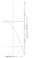
- FIG. It is a calibration curve created by measuring the infrared spectrum while changing the blending ratio of PVdF-CTFE copolymer (# 7500) and TMAEMA / TFSI.
- X is a halogen atom other than fluorine
- R 1 and R 2 are a hydrogen atom or a fluorine atom, and both may be the same or different. It is extremely important to use a polymer having a unit represented by the following, and a fluorine-based polymer obtained by graft polymerization of a molten salt monomer to such a polymer should be used for an electrolyte polymer composition. Therefore, although the reason is not clear, the ion transfer coefficient is remarkably improved.
- the halogen atom a chlorine atom is optimal, but a bromine atom and an iodine atom are also exemplified.
- Examples of the polymer having the — (CR 1 R 2 —CFX) — unit include Formula:-(CR 3 R 4 -CR 5 F) m- (CR 1 R 2 -CFX) n-
- X is a halogen atom other than fluorine
- R 1 , R 2 , R 3 , R 4 and R 5 are hydrogen atoms or fluorine atoms, which may be the same or different
- m is 65 to 99 mol%
- n is 1 to 35 mol%
- m is 99 to 65 mol%
- n is 35 to 1 mol%
- a copolymer represented by is optimal.
- m is preferably 65 to 99 mol%
- n is preferably 1 to 35 mol%
- more preferably m is 80 to 97 mol%
- n is It is 3 to 20 mol%
- optimally m is 92 to 97 mol%
- n is 3 to 8 mol%.
- the copolymer may be a block polymer or a random copolymer.
- other copolymerizable monomers can be used as long as the object of the present invention is not impaired.
- the molecular weight of the polymer is preferably 100,000 to 2,000,000, more preferably 300,000 to 1,500,000 as a weight average molecular weight.
- the weight average molecular weight is obtained from a molecular weight estimation formula from intrinsic viscosity.
- an atom transfer radical polymerization method using a transition metal complex can be applied.
- the transition metal coordinated to this complex draws out a halogen atom (for example, chlorine atom) other than fluorine of the copolymer and becomes a starting point, and the molten salt monomer is graft-polymerized to the polymer.
- a copolymer of a vinylidene fluoride monomer and a vinyl monomer containing fluorine and a halogen atom other than fluorine is preferably used.
- the backbone polymer has a fluorine atom and a halogen atom other than fluorine atom (for example, chlorine atom)
- the bond energy between carbon and halogen is lowered, so that the extraction of halogen atoms other than fluorine (for example, chlorine atom) by the transition metal is fluorine. It occurs more easily than atoms, and graft polymerization of the molten salt monomer is initiated.
- a transition metal halide As the catalyst used in the atom transfer radical polymerization, a transition metal halide is used, and in particular, a copper catalyst containing a copper atom such as copper (I) chloride, acetylacetonate copper (II), CuBr or the like is preferably used.
- the ligands forming the complex include 4,4′-dimethyl-2,2′-bipyridyl (bpy), tris (dimethylaminoethyl) amine (Me 6- TREN), N, N, N ′, N ′′ -penta. Methyldiethylenetriamine (PMDETA), etc.
- transition metal halide complexes formed of copper (I) chloride (CuCl) and 4,4′-dimethyl-2,2′-bipyridyl (bpy) are preferred.
- a solvent capable of dissolving a polymer having a — (CR 1 R 2 —CFX) — unit can be used, and a vinylidene fluoride monomer and a halogen atom other than fluorine and fluorine (for example, a chlorine atom) N-methylpyrrolidone, dimethylacetamide, dimethyl sulfoxide and the like which dissolve a copolymer with a vinyl monomer containing) can be used.
- the reaction temperature varies depending on the ligand of the complex used, but is usually in the range of 10 to 110 ° C.
- Electron beam polymerization is a preferred embodiment because it can be expected to undergo a crosslinking reaction of the polymer itself and a graft reaction of the monomer to the reinforcing material.
- the irradiation amount is preferably 0.1 to 50 Mrad, more preferably 1 to 20 Mrad.
- the monomer unit constituting the polymer is blended in a molar ratio of 97 to 60 mol% and the molten salt monomer in a molar ratio of 3 to 40 mol%, and the grafting rate is 3 in accordance with the target plastic property.
- the polymer may be a solution, a solid, or a molded body (film, porous film, etc.).
- the salt structure of a molten salt monomer having a quaternary ammonium salt structure composed of a quaternary ammonium cation and an anion (for example, a halogen atom-containing anion) and containing a polymerizable functional group is an aliphatic, aliphatic It includes a salt structure composed of a cyclic, aromatic or heterocyclic quaternary ammonium cation and an anion (for example, a halogen atom-containing anion, preferably a fluorine atom-containing anion).
- the “quaternary ammonium cation” here means an onium cation of nitrogen, and includes a heterocyclic onium ion such as imidazolium or pyridium.
- a salt structure comprising at least one ammonium cation selected from the following ammonium cation group and at least one anion selected from the following anion group is preferable.
- Ammonium cation group Pyrrolium cation, pyridinium cation, imidazolium cation, pyrazolium cation, benzimidazolium cation, indolium cation, carbazolium cation, quinolinium cation, pyrrolidinium cation, piperidinium cation, piperazinium cation, Alkyl ammonium cations (including those substituted with a hydrocarbon group having 1 to 30 carbon atoms, hydroxyalkyl, alkoxyalkyl). Any of them includes N and / or a ring having a hydrocarbon group having 1 to 30 carbon atoms (for example, 1 to 10 carbon atoms), a hydroxyalkyl group, or an alkoxyalkyl group.
- Anion group BF 4 ⁇ , PF 6 ⁇ , C n F 2n + 1 CO 2 ⁇ (n is an integer of 1 to 4), C n F 2n + 1 SO 3 ⁇ (n is an integer of 1 to 4), (FSO 2 ) 2 N -, (CF 3 SO 2) 2 N -, (C 2 F 5 SO 2) 2 N -, (CF 3 SO 2) 3 C -, CF 3 SO 2 -N-COCF 3 -, R-SO 2 - An anion containing a halogen atom such as N—SO 2 CF 3 — (R is an aliphatic group), ArSO 2 —N—SO 2 CF 3 — (Ar is an aromatic group), CF 3 COO — and COO ⁇ , HCOO - specific anions and the like.
- a halogen atom such as N—SO 2 CF 3 — (R is an aliphatic group), ArSO 2 —N—SO 2 CF 3 — (Ar
- halogen atom of an anion containing a halogen atom a fluorine atom is preferable, but a chlorine atom, a bromine atom, and an iodine atom are also exemplified.
- Species listed in the ammonium cation group and the anion group are excellent in heat resistance, reduction resistance or oxidation resistance, have a wide electrochemical window, and are suitably used for lithium batteries and capacitors.
- Examples of polymerizable functional groups in the monomer include cyclic ethers having a carbon-carbon unsaturated group such as a vinyl group, an acrylic group, a methacryl group, an acrylamide group, and an allyl group, an epoxy group, an oxetane group, and the like.
- Examples thereof include cyclic sulfides such as thiophene and isocyanate groups.
- the ammonium cation species having a polymerizable functional group is particularly preferably a trialkylaminoethyl methacrylate ammonium cation, a trialkylaminoethyl acrylate ammonium cation, a trialkylaminopropylacrylamide ammonium cation, or a 1-alkyl-3-vinyl.
- alkyl is an alkyl group having 1 to 10 carbon atoms.
- bis ⁇ (trifluoromethyl) sulfonyl ⁇ imide anion, 2,2,2-trifluoro-N- ⁇ (trifluoromethyl) sulfonyl) ⁇ acetimide anion bis ⁇
- examples include (pentafluoroethyl) sulfonyl ⁇ imide anion, bis ⁇ (fluoro) sulfonyl ⁇ imide anion, tetrafluoroborate anion, hexafluorophosphate anion, and trifluoromethanesulfonylimide anion.
- anions containing halogen atoms are more preferred.
- molten salt monomer a salt of the above-mentioned cationic species and anionic species
- trialkylaminoethyl methacrylate ammonium wherein alkyl is C 1 -C 10 alkyl
- bis ⁇ (trifluoromethyl ) Sulfonyl ⁇ imide wherein alkyl is C 1 -C 10 alkyl
- N-alkyl-N-allylammonium bis ⁇ (trifluoromethyl) sulfonyl ⁇ imide wherein alkyl is C 1 -C 10 alkyl
- 1- Vinyl-3-alkylimidazolium bis ⁇ (trifluoromethyl) sulfonyl ⁇ imide wherein alkyl is C 1 -C 10 alkyl
- 1-vinyl-3-alkylimidazolium tetrafluoroborate wherein alkyl is C 1- C 10 alkyl
- the graft ratio of the molten salt monomer to the copolymer is preferably 3 to 40 mol%, more preferably 3.5 to 35 mol%, and most preferably 7 to 30 mol%. is there. By satisfying the grafting ratio in this range, the object of the present invention can be achieved more suitably.
- the method for measuring the grafting rate will be described in Examples described later.
- the graft polymerization of the molten salt monomer may be used alone or may be copolymerized with another monomer that can be copolymerized therewith.
- the fluoropolymer obtained by the present invention is suitably used for electrolyte polymer compositions such as lithium ion batteries, lithium ion capacitors, PEM fuel cell batteries, dye-sensitized solar cells, electrolytic capacitors (capacitors), and organic EL cells. This point will be described below.
- the charge transfer ion source of the lithium ion battery and the lithium ion capacitor is typically a lithium salt, preferably a lithium salt comprising the following lithium cation and fluorine atom-containing anion. Salt is used.
- LiBF 4 LiPF 6 , C n F 2n + 1 CO 2 Li (n is an integer of 1 to 4), C n F 2n + 1 SO 3 Li (n is an integer of 1 to 4), (FSO 2 ) 2 NLi, (CF 3 SO 2 ) 2 NLi, (C 2 F 5 SO 2 ) 2 NLi, (CF 3 SO 2 ) 3 CLi, Li (CF 3 SO 2 —N—COCF 3 ), Li (R—SO 2 —N—SO 2 CF 3 ) (R is an aliphatic group such as an alkyl group), Li (ArSO 2 —N—SO 2 CF 3) (Ar is an aromatic group) and the like.
- the charge transfer ion source of the electrolyte can be a nitrogen-containing salt, and preferably the following alkylammonium cation (for example, tetraethylammonium cation, triethylmethylammonium cation) and fluorine atom
- alkylammonium cation for example, tetraethylammonium cation, triethylmethylammonium cation
- fluorine atom A salt consisting of a contained anion is used, Et 4 -N + BF 4 -, Et 3 Me-N + BF 4 - Et 4 -N + PF 6 -, Et 3 Me-N + PF 6 - and the like.
- the charge transfer ion source of the electrolyte can be a salt containing iodine, and preferably a redox pair electrolyte containing the following alkylimidazolium iodine is used.
- alkylimidazolium iodine there are Br ⁇ / Br 3 — pairs, quinone / hydroquinone pairs, and the like.
- the charge transfer ion source can be a proton donor corresponding to the anion species of the quaternary ammonium salt structure of the molten salt monomer.
- the charge transfer ion source can be a proton donor corresponding to the anion species of the quaternary ammonium salt structure of the molten salt monomer.
- HBF 4 HPF 6 , C n F 2n + 1 CO 2 H (n is an integer of 1 to 4), C n F 2n + 1 SO 3 H (n is an integer of 1 to 4), (FSO 2 ) NH, (CF 3 SO 2 ) NH, (C 2 F 5 SO 2 ) NH, (CF 3 SO 2 ) 3 NH, (CF 3 —SO 2 —NH—COCF 3 ), and (R—SO 2 —NH—SO 2 CF 3 ) (R is an aliphatic group or an aromatic group).
- a PEM fuel cell battery can be obtained by disposing these proton source, molten salt monomer, and fluor
- the charge transfer ion source of an electrolyte composed of an electron transport layer and a light emitting layer is the same material as in the case of a lithium ion secondary battery and a dye-sensitized solar cell. Can be used to improve carrier transport of organic materials.
- the charge transfer ion source can be a proton donor corresponding to the anion species of the quaternary ammonium salt structure of the molten salt monomer. Those are preferred.
- a PEM fuel cell battery can be obtained by disposing these proton source and fluoropolymer between the opposing negative electrode and positive electrode.
- the charge transfer ion source is typically, I 3 - / I - is a redox pair, Additional Br 3 - / Br - pairs, quinone / hydroquinone pairs etc. is there.
- a dye-sensitized solar cell can be obtained by disposing these ion source and fluorine-based polymer between a working electrode having an oxide semiconductor film on which a dye is adsorbed and a conductive counter electrode.
- the organic materials used in organic EL cells using the basic technology of dye-sensitized solar cells are vulnerable to oxygen and moisture, the technology for sealing from the outside has been enhanced, but there is a limit to the long life. Because of the need to use stable organic molecules, an organic EL cell with improved carrier movement of organic materials can be obtained by arranging these ion source and fluorine polymer in the electron transport layer and the light emitting layer. .
- an electrolytic capacitor (capacitor) can be obtained by disposing a fluorine-based polymer that does not include the ion source between opposing conductive electrodes.
- the fluoropolymer obtained by the present invention is used as a polymer electrolyte composition, in particular, a lithium ion battery, a lithium ion capacitor, a PEM fuel cell battery, a dye-sensitized solar cell, an electrolytic capacitor (capacitor), an organic EL. It is preferably used as an electrolyte layer between opposing electrodes of an electrochemical device such as a cell.
- the electrolyte layer include an electrolyte membrane, a coating layer on the negative electrode, a coating layer on the positive electrode, and a coating layer on the separator.
- the fluoropolymer preferably has a multilayer structure (lamella structure) laminated at a molecular level.
- a lithium ion battery typically includes a negative electrode having an active material layer made of a carbon material that occludes and releases lithium ions, typically graphite, LiCoO 2 , LiNi n Co 1-n , LiFePO 4 , LiMn 2 O. 4 and LiNi n Me 1-n O 2 or LiCo n Me 1-n O 2 (Me is one or more selected from Co, Ni, Mn, Sn, Al, Fe, Sb, etc.)
- a positive electrode having an active material layer made of a composite metal oxide containing lithium that absorbs and releases lithium ions is used.
- the positive electrode active material is a metal oxide that does not contain Li, such as manganese dioxide, TiS 2 , MoS 2 , NbS 2 , MoO 3, and V 2 O 5 , or Sulfides can be used.
- a lithium ion capacitor hard carbon, which is a capacitor electrode, is usually used for the negative electrode instead of graphite, but the electrolyte is the same as that of the lithium ion battery.
- a porous electrode provided with a catalyst represented by Pt is generally used.
- a semiconductor electrode in which a dye is adsorbed on an oxide semiconductor film such as TiO 2 or ZnO formed on a substrate having a conductive surface is generally used as a working electrode.
- the counter electrode is a conductive electrode typified by a platinum-deposited glass substrate.
- the electrode pair of the electrolytic capacitor / capacitor the same hard carbon electrode as the electrode pair used in the conventional liquid electrolytic capacitor can be used.
- the fluorine-based polymer obtained by the present invention is a non-flammable / flame retardant of an ion conductive polymer such as a lithium ion battery, a lithium ion capacitor, various capacitors, a capacitor, a dye-sensitized solar cell, a PEM fuel cell battery, and an organic EL cell. Can be applied to electrolytes.
- the ion conductive polymer can be used as a surface coating agent for nanoparticulate carbon, a rare metal, or a metal oxide that is an active material for a lithium ion battery electrode.
- the ion conductive polymer can be used as conductive composite resin particles having a particle diameter of from submicron to 10 ⁇ m by being composited with nanoparticles.
- this ion conductive polymer is sprayed, dipped, coated, etc. for the purpose of imparting non-flammability, flame retardancy and ionic conductivity to the surface of a resin material kneaded or molded into an insulating plastic.
- the cured film can be formed by coating and thermal polymerization or UV (ultraviolet) irradiation.
- the present invention is illustrated by means of non-limiting examples. These examples are intended for electrolytes of lithium ion batteries and lithium ion capacitors, but those skilled in the art will recognize that other electrochemical devices (eg, PEMs) can be obtained by modifying the charge transfer ion source as described above. These embodiments can be easily modified for application to fuel cell batteries, dye-sensitized solar cells, organic EL cells, and the like. In the examples, all parts and percentages are by weight unless otherwise specified. The compounds synthesized in the examples were identified by IR spectrum and NMR spectrum.
- MPP ⁇ Br 110 g was dissolved in 100 ml of ion-exchanged water, and an aqueous solution in which 158 g of lithium bis ⁇ (trifluoromethyl) sulfonyl ⁇ imide (Li ⁇ TFSI) was dissolved in 100 ml of ion-exchanged water was dropped and reacted.
- Li ⁇ TFSI lithium bis ⁇ (trifluoromethyl) sulfonyl ⁇ imide
- MPP / TFSI was separated, washed with 100 ml of ion exchange water, and purified by repeated separation. And it dehydrated under vacuum at 30 degreeC and obtained 169g of MPP * TFSI.
- Synthesis example 2 of molten salt monomer Diallyldimethylammonium bis ⁇ (trifluoromethyl) sulfonyl ⁇ imide (DAA ⁇ TFSI) reaction: While stirring 161.5 g of diallyldimethylammonium chloride (trade name DADMAC 60% solution, manufactured by Daiso Corporation), a solution obtained by dissolving 316 g of Li ⁇ TFSI in 300 ml of ion-exchanged water was added. The diallyldimethylammonium bis ⁇ (trifluoromethyl) sulfonyl ⁇ imide (DAA ⁇ TFSI) obtained by the reaction was separated, purified with repeated washing and washing with 200 ml of ion-exchanged water. And it dehydrated under vacuum at 30 degreeC, and obtained DAA * TFSI365.4g.
- DAA ⁇ TFSI Diallyldimethylammonium bis ⁇ (trifluoromethyl) sulfonyl ⁇ imide
- Synthesis example 3 of molten salt monomer Trimethylaminoethyl methacrylate / bis ⁇ (trifluoromethyl) sulfonyl ⁇ imide (TMAEMA / TFSI) reaction: 187.5 g of dimethylaminoethyl methacrylate methyl chloride quaternary salt (QDM) was dissolved in 300 ml of ion-exchanged water, and 367.5 g of a 70% aqueous solution of H ⁇ TFSI was slowly added dropwise to react with stirring.
- TMAEMA / TFSI Trimethylaminoethyl methacrylate / bis ⁇ (trifluoromethyl) sulfonyl ⁇ imide
- TMAEMA ⁇ TFSI trimethylaminoethyl methacrylate ⁇ bis ⁇ (trifluoromethyl) sulfonyl ⁇ imide
- Synthesis example 4 of molten salt monomer TFSI conversion reaction of dimethylaminopropylacrylamide methyl chloride quaternary salt (TMAPAA / TFSI): Dimethylaminopropylacrylamide methyl chloride quaternary salt (DMAPAA-Q) 75% aqueous solution 106.7 g was diluted with ion-exchanged water 50 ml, and 156 g of H / TFSI 70% aqueous solution was slowly added dropwise with stirring.
- TMAPAA / TFSI dimethylaminopropylacrylamide methyl chloride quaternary salt
- TMAPAA ⁇ TFSI The trimethylaminopropylacrylamide ⁇ (trifluoromethyl) sulfonyl ⁇ imide (TMAPAA ⁇ TFSI) obtained by the reaction was separated, purified with 100 ml of ion-exchanged water and repeated separation. And it dehydrated under vacuum at 30 degreeC, and obtained 79 g of TMAPAA * TFSI. TMAPAA ⁇ TFSI was similarly obtained when Li salt of TFSI was used as an alternative to H ⁇ TFSI.
- Synthesis example 5 of molten salt monomer TFSI conversion reaction of dimethylaminoethyl methacrylate methyl chloride quaternary salt (TMAEA ⁇ TFSI): 50 g of dimethylaminoethyl methacrylate methyl chloride quaternary salt (Kojin DMAEA-Q) was dissolved in 50 ml of ion-exchanged water, and 104 g of a 70% aqueous solution of H.TFSI was slowly added dropwise to react with stirring.
- TFA / TFSI trimethylaminoethyl acrylate / bis (trifluoromethyl) sulfonylimide
- Synthesis example 6 of molten salt monomer Tetrafluoroborate (BF 4 ) reaction of dimethylaminoethyl methacrylate methyl chloride quaternary salt (TMAEMA ⁇ BF 4 ): 174.5 g of dimethylaminoethyl methacrylate methyl chloride quaternary salt (QDM) was dissolved in 300 ml of ion-exchanged water, and 124.4 g of a 70% aqueous solution prepared by dissolving LiBF 4 powder with stirring was slowly added dropwise to react.
- TMAEMA ⁇ BF 4 dimethylaminoethyl methacrylate methyl chloride quaternary salt
- TMAEMA / BF 4 trimethylaminoethyl methacrylate / tetrafluoroborate obtained by the reaction was separated, washed with 200 ml of ion-exchanged water, and purified by repeated separation. And give TMAEMA ⁇ BF 4 174.0g in vacuo dehydrated at 30 ° C..
- DMAPAA-Q dimethylaminopropylacrylamide methyl chloride quaternary salt
- DMAEA-Q dimethylaminoethyl methacrylate methyl chloride quaternary salt
- Synthesis example 7 of molten salt monomer Hexafluorophosphoric acid (PF 6 ) conversion reaction of dimethylaminoethyl methacrylate methyl chloride quaternary salt (TMAEMA ⁇ PF 6 ): 182.3 g of dimethylaminoethyl methacrylate methyl chloride quaternary salt (QDM) was dissolved in 300 ml of ion-exchanged water, and 146.8 g of a 70% aqueous solution prepared by dissolving LiPF 6 powder with stirring was slowly dropped and reacted.
- PF 6 Hexafluorophosphoric acid
- TMAEMA ⁇ PF 6 dimethylaminoethyl methacrylate methyl chloride quaternary salt
- TMAEMA ⁇ PF 6 trimethylaminoethyl methacrylate hexafluorophosphate obtained by the reaction was separated, washed with 200 ml of ion-exchanged water, and purified by repeated separation. And give TMAEMA ⁇ PF 6 214.0g in vacuo dehydrated at 30 ° C..
- the hexafluorophosphate (PF6) reaction was similarly carried out for dimethylaminopropylacrylamide methyl chloride quaternary salt (DMAPAA-Q) and dimethylaminoethyl acrylate methyl chloride quaternary salt (DMAEA-Q) of Synthesis Examples 4 and 5.
- DMAPAA-Q dimethylaminopropylacrylamide methyl chloride quaternary salt
- DMAEA-Q dimethylaminoethyl acrylate methyl chloride quaternary salt
- Synthesis example 8 of molten salt monomer Bisfluorosulfonylimide (FSI) reaction of dimethylaminoethyl methacrylate methyl chloride quaternary salt (TMAEMA ⁇ FSI): 183.6 g of dimethylaminoethyl methacrylate methyl chloride quaternary salt (QDM) was dissolved in 300 ml of ion-exchanged water, and 304.5 g of a 70% aqueous solution prepared by dissolving KFSI powder with stirring was slowly added dropwise to react.
- FSI Bisfluorosulfonylimide
- TMAEMA ⁇ FSI dimethylaminoethyl methacrylate methyl chloride quaternary salt
- TMAEMA ⁇ FSI Trimethylaminoethyl methacrylate bisfluorosulfonylimide (TMAEMA ⁇ FSI) obtained by the reaction was separated, washed with 200 ml of ion-exchanged water, and purified by repeated separation. And it dehydrated under vacuum at 30 degreeC, and 249.1g of TMAEMA * FSI was obtained.
- Synthesis example 9 of molten salt monomer For the methylpropylpiperidine bromide (MPP ⁇ Br) and diallyldimethylammonium chloride (DADMAC) of Synthesis Examples 1 and 2, the bisfluorosulfonylimide (FSI) reaction was carried out in the same manner as in Synthesis Example 8 to produce MPP ⁇ FSI. And DAA ⁇ FSI were obtained.
- MPP ⁇ Br methylpropylpiperidine bromide
- DADMAC diallyldimethylammonium chloride
- a 1 L three-necked flask was equipped with a condenser, a stirring device, and a dropping device, and 6 g of PVdF-CTFE copolymer # 7500 and 80 g of N-methylpyrrolidone (NMP) were added and heated to 80 ° C. in an oil bath and dissolved by stirring. .
- NMP N-methylpyrrolidone
- the reaction product was further washed with a methanol solution and dried to obtain a crude polymer.
- the crude polymer was pulverized, and a mixed solvent of 40% acetone and 60% methanol was added and stirred.
- the ungrafted ionic liquid polymer and the unreacted molten salt monomer were dissolved, and the graft polymer swelled and settled, and thus was separated by a centrifuge. This extraction operation was repeated to obtain a graft polymer containing no homopolymer.
- the yield was measured by drying in a vacuum dryer at 30 ° C., and the infrared spectrum was measured to calculate the grafting rate (mol%). The results are shown in Table 1.
- FIGS. 1 and 2 Comparison of IR charts of the PVdF-CTFE copolymer (# 7500) and the TMAEMA / TFSI graft polymer of Example 3 is shown in FIGS. 1 and 2, respectively.
- the frequency (cm ⁇ 1 ) and transmittance (%) corresponding to each peak number in FIG. Table 3 shows the frequency (cm ⁇ 1 ) and transmittance (%) corresponding to each peak number in FIG.
- TMAEMA ⁇ TFSI grafted PVdF (Example 3) shows a strong carbonyl absorption peak at 1727-1733 cm -1 and grafting.
- * 1350-1352 cm ⁇ 1 is an absorption peak of an anion.
- the absorption peak of PVdF-CTFE copolymer (# 7500) is in the vicinity of 878-882 cm ⁇ 1 , and this peak is reduced in graft PVdF (Example 3).
- the absorption peaks are shown in the two IR charts (FIGS. 1 and 2) of the PVdF-CTFE copolymer (# 7500) and the TMAEMA / TFSI graft polymer of Example 3 as described above. From the comparison, it was confirmed that TMAEMA ⁇ TFSI was clearly grafted.
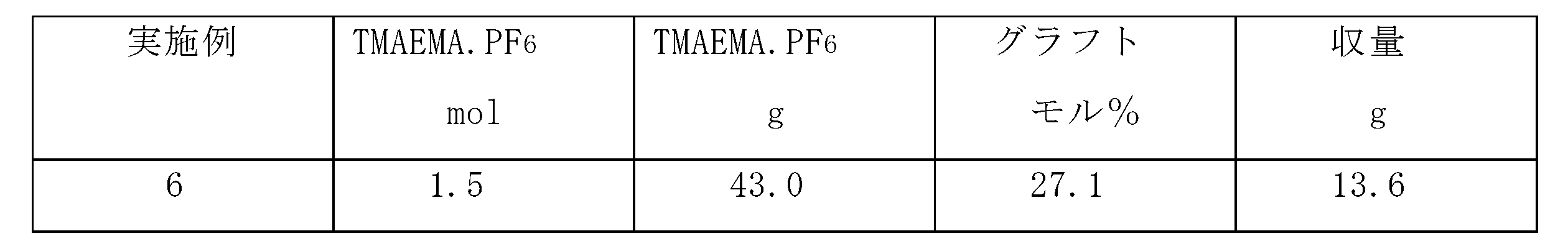
- Example 6 In Example 3, graft polymerization was carried out in the same manner except that the compound name trimethylaminoethyl methacrylate / hexafluorophosphate (TMAEMA / PF 6 ) (Synthesis Example 7) 8943 g was used instead of TMAEMA / TFSI. The results are shown in Table 5.
- Example 7 In Example 3, graft polymerization was carried out in the same manner except that 61.5 g of trimethylaminopropylacrylamide ⁇ (trifluoromethyl) sulfonyl ⁇ imide (TMAPAA ⁇ TFSI) (Synthesis Example 4) was used instead of TMAEMA ⁇ TFSI. The results are shown in Table 6.
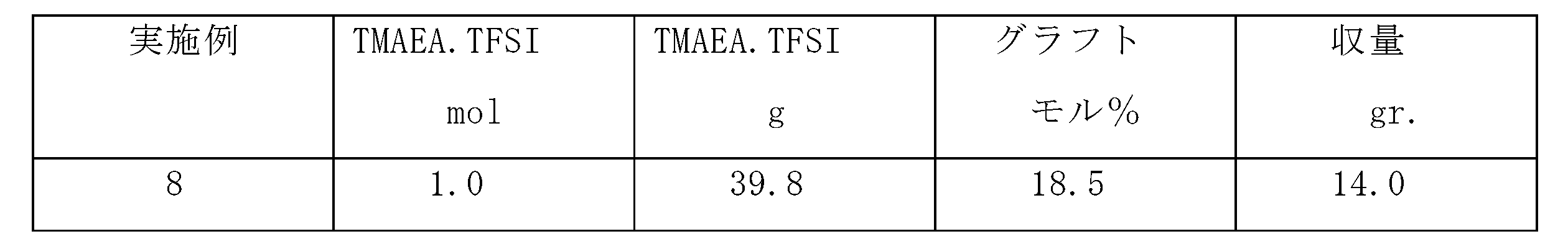
- Example 8 In Example 3, graft polymerization was carried out in the same manner except that 39.8 g of trimethylaminoethyl methacrylate ⁇ bis ⁇ (trifluoromethyl) sulfonyl ⁇ imide (TMAEA ⁇ TFSI) (Synthesis Example 5) was used instead of TMAEMA ⁇ TFSI. Reacted. The results are shown in Table 7.
- Example 9 In Example 3, a graft polymerization reaction was conducted in the same manner except that 34.7 g of trimethylaminoethyl methacrylate bisfluorosulfonylimide (TMAEMA.FSI) (Synthesis Example 8) was used instead of TMAEMA.TFSI as the molten salt monomer. . The results are shown in Table 8.
- TMAEMA.FSI trimethylaminoethyl methacrylate bisfluorosulfonylimide
- Comparative Example 1-3 instead of the PVdF-CTFE copolymer (# 7500) of Example 3, a vinylidene fluoride polymer containing no chlorine- (CH 2 -CF 2 )- ⁇ manufactured by Kureha Chemist, trade name # 1700 (Comparative Example 1) ), Trade name, Kynar 461 (Comparative Example 2) ⁇ , and vinylidene fluoride (PVdF) -hexafluoropropylene (HFP) copolymer (Solvay Kynar 2801) (Comparative Example 3) were used.
- the graft ratio decreases when a trunk polymer containing no chlorine is used.
- Example 10 Preparation of new composite electrolyte precursor solution: As in Synthesis Example 1, 1-methyl-1-propylpiperidinium bis ⁇ (trifluoromethyl) sulfonyl ⁇ imide (MPP ⁇ TFSI) was synthesized. Further, as in Synthesis Example 2, diallyldimethylammonium bis ⁇ (trifluoromethyl) sulfonyl ⁇ imide [DAA ⁇ TFSI] was synthesized. As a graft polymer, a polyfluorinated polymer (TMAEMA-graft polymer) obtained by graft polymerization of trimethylaminoethyl methacrylate was synthesized as in Example 3.
- TMAEMA-graft polymer polyfluorinated polymer obtained by graft polymerization of trimethylaminoethyl methacrylate was synthesized as in Example 3.
- a new non-combustible composite electrolyte precursor solution was prepared by stirring in the same manner. Thereafter, 1.6 g of molten salt monomer DAA ⁇ TFSI having a reactive group was added to the uniformly dispersed solution, and the mixture was stirred with a homogenizer to prepare a novel noncombustible composite electrolyte precursor solution.
- Make a positive electrode paint by weight% solid content apply it to the aluminum foil as the current collector, raise the temperature from 70 ° C to 100 ° C, further raise the temperature to 130 ° C, and heat and dry for a total of 45 minutes to produce the positive electrode To do. Furthermore, it pressed so that the positive electrode single-sided layer thickness might be set to 15 micrometers.
- a negative electrode mixture solution was prepared by mixing 95% by weight of natural graphite as a negative electrode active material and 2% by weight of ketjen black as a conductive agent in 3% by weight of the composite polymer electrolyte precursor solution.
- a negative electrode was prepared by coating a copper foil as a current collector with a weight% solid content negative electrode coating, raising the temperature from 80 ° C. to 110 ° C., further raising the temperature to 130 ° C., and heating and drying for a total of 45 minutes. Furthermore, it pressed so that the positive electrode single-sided layer thickness might be set to 20 micrometers.
- Electrode electrolyte membrane The composite polymer electrolyte precursor solution, which is nonflammable, is coated on a 100 ⁇ m polyester film (T type manufactured by Toray Industries, Inc.), heated at 130 for 30 minutes, and dried to form a composite polymer electrolyte membrane with a thickness of 20 ⁇ m on the polyester film. Formed.
- the composite polymer electrolyte membrane surface was superimposed on the coating surface of the positive electrode, laminated between rolls at 130 ° C., and then the polyester film was peeled off to produce a positive electrode / electrolyte membrane laminated sheet.
- the coating surface of the negative electrode was overlapped on the electrolyte membrane surface of the laminated sheet, and similarly laminated between rolls at 130 ° C. to prepare a positive electrode / electrolyte membrane / negative electrode laminate.
- This laminate was gelled at 150 ° C. ⁇ 10 kg / cm 2 for 30 minutes while thermocompression bonding.
- the graft polymer in the electrolyte membrane formed a lamellar lamellar structure.
- the laminate was punched to a diameter of 15 mm, placed in an aluminum container, and a spring and lid of the same material were stacked and pressed to produce a coin-type cell.
- Charging / discharging cycle test conditions Charging was performed at a constant current with a current of 1 mA and a final voltage of 4.0 V. The discharge was a constant current discharge at a current of 1 mA and a final voltage of 2.5V.
- the discharge capacity (%) the discharge capacity at the initial stage of charge / discharge was 96%, and the discharge capacity of 99% was maintained even at the 20th cycle.
- Example 11 to 18 In Example 10 (using the graft polymer of Example 3), instead of the graft polymer of Example 3, the graft polymers prepared in Examples 1 to 9 (excluding Example 3) were used. In the same manner, a composite electrolyte membrane and a cell were obtained. Table 11 shows the test results (membrane conductive performance, ion conductivity, nonflammability, mechanical strength: tensile strength, etc.) of this cell.
- Example 10 using the graft polymer of Example 3
- the graft polymer prepared in Comparative Examples 1 to 3 was used, and the composite electrolyte membrane was similarly used. And a cell was obtained. The test results of this cell are also shown in Table 11.
- Example 10 (using the graft polymer of Example 3)
- Example 11 (using the graft polymer of Example 1)
- Example 12 (using the graft polymer of Example 2)
- Example 13 (using the graft polymer of Example 4)
- Example 14 (using the graft polymer of Example 5)
- Example 15 (using the graft polymer of Example 6)
- Example 16 (using the graft polymer of Example 7)
- Example 17 using the graft polymer of Example 8)
- Example 18 (using the graft polymer of Example 9)
- Comparative Example 4 (using the graft polymer of Comparative Example 1) Comparative Example 5 (using the graft polymer of Comparative Example 2) Comparative Example 6 (using the graft polymer of Comparative Example 3)
- the safety test (The aluminum laminated cell use by the same cell specification) (needle stick test) was done. Specifically, a needle penetration test was performed under the following conditions using a safety test apparatus capable of overcharging / discharging, crushing, and needle (nail) penetration tests.
- Test equipment Battery safety test equipment (Miwa Manufacturing Co., Ltd.) (Equipment for nail / needle stick test, heat crush test, etc.) Needle specification: 0.8 mm diameter cotton needle used Stitching speed: 1 mm / second
- Needle specification 0.8 mm diameter cotton needle used Stitching speed: 1 mm / second
- the present invention it is possible to provide a method for producing a fluorine-based polymer for obtaining a polymer electrolyte composition in which an ion transfer coefficient (transport number), for example, a lithium ion transfer coefficient is remarkably improved.
- an ion transfer coefficient (transport number) for example, a lithium ion transfer coefficient is remarkably improved.
- the fluoropolymer obtained by the method of the present invention is used in a composite polymer electrolyte composition, the ion transfer coefficient (transport number) is extremely high. For this reason, for example, in an electrolyte composition for a lithium ion battery. When used, a high performance lithium battery can be obtained.
- the composite polymer electrolyte composition using the fluoropolymer obtained by the method of the present invention is nonflammable, there is little risk of ignition, and the composite polymer electrolyte composition obtained using this composition has high risk.
- Molecular electrolyte films are also excellent in mechanical properties such as plasticity and tensile strength.
- the present invention has high industrial applicability.
Abstract
Description
式中、Xは、フッ素以外のハロゲン原子であり、
R1及びR2は、水素原子又はフッ素原子であり、両者は同一であって
もよいし異なっていてもよい、
で示される単位を有する重合体に、4級アンモニウムカチオンとアニオンからなる4級アンモニウム塩構造を有し、かつ重合性官能基を有する溶融塩単量体をグラフト重合することを特徴とするフッ素系重合体の製法によって達成される。
式:-(CR1R2-CFX)-
式中、Xは、フッ素以外のハロゲン原子であり、
R1及びR2は、水素原子又はフッ素原子であり、両者は同一であって
もよいし異なっていてもよい、
で示される単位を有する重合体に配合し、前記重合体に前記溶融塩単量体をグラフト重合して得たフッ素系重合体を含む、複合高分子電解質組成物によって、好適に達成される。なおここで、単量体組成物とは、前記溶融塩単量体以外に、後述する電荷移動イオン源等の支持塩、あるいはビニレンカーボネート類、ビニレンアセテート、2-シアノフラン、2-チオフェンカルボニトリル、アクリロニトリル等のSEI(固体電解質界面相:Solid Electrolyte Interphase)膜形成素材あるいは溶剤等を含む単量体組成物を包含する。
式中、Xは、フッ素以外のハロゲン原子であり、R1及びR2は、水素
原子又はフッ素原子であり、両者は同一であってもよいし異なってい
てもよい、
で示される単位を有する重合体を使用することは極めて重要であり、このような重合体に溶融塩単量体をグラフト重合して得たフッ素系重合体を電解質高分子組成物に使用することにより、その理由は定かではないが、イオン移動係数が著しく向上する。ここでハロゲン原子としては、塩素原子が最適であるが、臭素原子、ヨウ素原子も挙げられる。
式:-(CR3R4-CR5F)m-(CR1R2-CFX)n-
式中、Xは、フッ素以外のハロゲン原子であり、
R1、R2、R3、R4及びR5は、水素原子又はフッ素原子であり、これ
らは同一であってもよいし異なっていてもよく、
mは65~99モル%であり、
nは1~35モル%である、
で示される共重合体が好適であり、特に、
式;-(CH2-CF2)m-(CF2-CFCl)n-
式中、mは99~65モル%であり、
nは35~1モル%である、
で示される共重合体が最適である。
mとnの合計を100モル%とした場合、mは65~99モル%、nは1~35モル%であることが好適であり、より好適にはmは80~97モル%、nは3~20モル%であり、最適にはmは92~97モル%、nは3~8モル%である。
前記共重合体は、ブロック重合体であっても、ランダム共重合体であってもよい。また、他の共重合し得る単量体を、本発明の目的が阻害されない範囲で使用することもできる。
原子移動ラジカル重合で使用される触媒は遷移金属ハロゲン化物が用いられ、特に塩化銅(I)、アセチルアセトナート銅(II)、CuBr等の銅原子を含む銅触媒が好適に用いられる。また錯体を形成するリガンドとしては4,4’-ジメチル-2,2’-ビピリジル(bpy)、トリス(ジメチルアミノエチル)アミン(Me6-TREN)、N,N,N’,N”-ペンタメチルジエチレントリアミン(PMDETA)等が使用される。中でも、塩化銅(I)(CuCl)と4,4’-ジメチル-2,2’-ビピリジル(bpy)とで形成される遷移金属ハロゲン化錯体を好適に使用することができる。
反応溶媒としては、-(CR1R2-CFX)-単位を有する重合体を溶解可能な溶媒を使用することができ、フッ化ビニリデン単量体とフッ素及びフッ素以外のハロゲン原子(例えば塩素原子)を含むビニル単量体との共重合体を溶解するN-メチルピロリドン、ジメチルアセトアミド、ジメチルスルフォキシド等を用いることができる。反応温度は使用する錯体のリガンドによって異なるが、通常、10~110℃の範囲である。
重合体を構成するモノマー単位を97~60モル%と溶融塩単量体を3~40モル%のモル比の範囲になるように配合、目標とする可塑物性に合わせて、グラフト化率が3~40モル%になるようにグラフト重合する。溶融塩単量体を前記重合体にグラフト重合する場合、前記重合体は溶液、固体、成形体(フイルム、多孔フイルム等)のいずれであってもよい。
ピロリウムカチオン、ピリジニウムカチオン、イミダゾリウムカチオン、ピラゾリウムカチオン、ベンズイミダゾリウムカチオン、インドリウムカチオン、カルバゾリウムカチオン、キノリニウムカチオン、ピロリジニウムカチオン、ピペリジニウムカチオン、ピペラジニウムカチオン、アルキルアンモニウムカチオン(但し、炭素原子数1~30の炭化水素基、ヒドロキシアルキル、アルコキシアルキルで置換されているものを含む)が挙げられる。いずれも、N及び/又は環に炭素原子数1~30(例えば、炭素原子数1~10)の炭化水素基、ヒドロキシアルキル基、アルコキシアルキル基が結合しているものを含む。
BF4 -、PF6 -、CnF2n+1CO2 -(nは、1~4の整数)、CnF2n+1SO3 -(nは、1~4の整数)、(FSO2)2N-、(CF3SO2)2N-、(C2F5SO2)2N-、(CF3SO2)3C-、CF3SO2-N-COCF3 -、R-SO2-N-SO2CF3 -(Rは、脂肪族基)、ArSO2-N-SO2CF3 -(Arは、芳香族基)、CF3COO-等のハロゲン原子を含むアニオン及びCOO-、HCOO-等の特定アニオンが挙げられる。ハロゲン原子を含有するアニオンのハロゲン原子としては、フッ素原子が好適であるが、塩素原子、臭素原子、ヨウ素原子も例示される。
LiBF4、LiPF6、CnF2n+1CO2Li(nは、1~4の整数)、
CnF2n+1SO3Li(nは、1~4の整数)、(FSO2)2NLi、
(CF3SO2)2NLi、(C2F5SO2)2NLi、
(CF3SO2)3CLi、Li(CF3SO2-N-COCF3)、
Li(R-SO2-N-SO2CF3)(Rは、アルキル基等の脂肪族基)、
Li(ArSO2-N-SO2CF3)(Arは、芳香族基)等。
Et4-N+BF4 -、Et3Me-N+BF4 -
Et4-N+PF6 -、Et3Me-N+PF6 -等。
トリアルキルイミダゾリウムヨウ素、1,2-ジメチル-3-プロピルイミダゾリウムヨウ素、ヘキシルメチルイミダゾリウムヨウ素等。
HBF4、HPF6、CnF2n+1CO2H(nは、1~4の整数)、CnF2n+1SO3H(nは、1~4の整数)、(FSO2)NH、(CF3SO2)NH、(C2F5SO2)NH、(CF3SO2)3NH、(CF3-SO2-NH-COCF3)、及び(R-SO2-NH-SO2CF3)(Rは、脂肪族基又は芳香族基)。
これらのプロトン源、溶融塩単量体及びフッ素系重合体を、対向する負極と正極の間に配置することによりPEM燃料セル電池を得ることができる。
HBF4、HPF6、CnF2n+1CO2H(nは、1~4の整数)、CnF2n+1SO3H(nは、1~4の整数)、(FSO2)NH、(CF3SO2)NH、(C2F5SO2)NH、(CF3SO2)3NH、(CF3-SO2-NH-COCF3)、及び(R-SO2-NH-SO2CF3)(Rは、脂肪族基又は芳香族基)等。
これらのプロトン源及びフッ素系重合体を、対向する負極と正極の間に配置することによりPEM燃料セル電池を得ることができる。
これらのイオン源及びフッ素系重合体を、色素を吸着させた酸化物半導体膜を有する作用極と、導電性対極の間に配置することにより、色素増感太陽電池を得ることができる。更に、色素増感太陽電池の基礎技術を活用して有機ELセルにて使用される有機材料が酸素や湿気に弱いため、外部から封止する技術が高められているが、長寿命に限界があり安定な有機分子を利用する必要性から、これらのイオン源及びフッ素系重合体を電子輸送層と発光層に配置することにより、有機材料のキャリア移動を向上した有機ELセルを得ることができる。
実施例中、すべての部及び%は特記しない限り重量基準による。実施例中で合成した化合物はIRスペクトル、NMRスペクトルで同定した。
1-メチル-1-プロピルピペリジニウムビス{(トリフルオロメチル)スルフォニル}イミド(MPP・TFSI)化反応:
N-メチルピペリジン99.2gをアセトン300mlに溶かし、50℃でプロピルブロミド120.9gをゆっくり滴下した。8時間反応したのち冷却して1-メチル-1-プロピルピペリジンブロミド(MPP・Br)の結晶を得た。その結晶をアセトンでろ過・洗浄し、乾燥してMPP・Br113gを得た。MPP・Br110gを100mlのイオン交換水に溶解し、リチウムビス{(トリフルオロメチル)スルフォニル}イミド(Li・TFSI)158gをイオン交換水100mlに溶かした水溶液を滴下して反応させた。MPP・TFSIは分液し、イオン交換水100mlで洗浄、分離を繰り返して精製した。そして30℃で真空下脱水してMPP・TFSI 169gを得た。
ジアリルジメチルアンモニウムビス{(トリフルオロメチル)スルフォニル}イミド(DAA・TFSI)化反応:
ジアリルジメチルアンモニウムクロリド(ダイソー社製 商品名DADMAC 60%溶液)161.5gを攪拌しながら、Li・TFSI 316gを300mlのイオン交換水に溶解した溶液を加えた。反応で得られたジアリルジメチルアンモニウムビス{(トリフルオロメチル)スルフォニル}イミド(DAA・TFSI)は分液し、イオン交換水200mlで洗浄、分離を繰り返して精製した。そして30℃で真空下脱水してDAA・TFSI365.4gを得た。
トリメチルアミノエチルメタクリレート・ビス{(トリフルオロメチル)スルフォニル}イミド(TMAEMA・TFSI)化反応:
ジメチルアミノエチルメタクリレート塩化メチル4級塩(QDM)187.5gをイオン交換水300mlに溶かし、攪拌しながらH・TFSI 70%水溶液367.5gをゆっくり滴下して反応させた。反応で得られたトリメチルアミノエチルメタクリレート・ビス{(トリフルオロメチル)スルフォニル}イミド(TMAEMA・TFSI)は分液し、イオン交換水200mlで洗浄、分離を繰り返して精製した。そして30℃で真空下脱水してTMAEMA・TFSI 376.5gを得た。H・TFSIの代替としてTFSIのLi塩を使用した場合にもTMAEMA・TFSIを同様に得た。
ジメチルアミノプロピルアクリルアミド塩化メチル4級塩のTFSI化反応(TMAPAA・TFSI):
ジメチルアミノプロピルアクリルアミド塩化メチル4級塩(DMAPAA-Q)75%水溶液106.7gをイオン交換水50mlで希釈し、攪拌しながらH・TFSI 70%水溶液156gをゆっくり滴下して反応させた。反応で得られたトリメチルアミノプロピルアクリルアミド{(トリフルオロメチル)スルフォニル}イミド(TMAPAA・TFSI)は分液し、イオン交換水100mlで洗浄、分離を繰り返して精製した。そして30℃で真空下脱水してTMAPAA・TFSI 79gを得た。H・TFSIの代替としてTFSIのLi塩を使用した場合にもTMAPAA・TFSIを同様に得た。
ジメチルアミノエチルメタクリレート塩化メチル4級塩のTFSI化反応(TMAEA・TFSI):
ジメチルアミノエチルメタクリレート塩化メチル4級塩(興人DMAEA-Q)50gをイオン交換水50mlに溶かし、攪拌しながらH・TFSI 70%水溶液を104gゆっくり滴下して反応させた。反応で得られたトリメチルアミノエチルアクリレート・ビス(トリフルオロメチル)スルフォニルイミド(TMAEA・TFSI)は分液し、イオン交換水60mlで洗浄、分離を繰り返して精製した。そして30℃で真空下脱水してTMAEA・TFSI 90gを得た。H・TFSIの代替としてTFSIのLi塩を使用した場合にもTMAEA・TFSIを同様に得た。
ジメチルアミノエチルメタクリレート塩化メチル4級塩のテトラフルオロボレート(BF4)化反応(TMAEMA・BF4):
ジメチルアミノエチルメタクリレート塩化メチル4級塩(QDM)175.5gをイオン交換水300mlに溶かし、攪拌しながらLiBF4粉末を溶解して作製した70%水溶液124.4gをゆっくり滴下して反応させた。反応で得られたトリメチルアミノエチルメタクリレート・テトラフルオロボレート(TMAEMA・BF4)は分液し、イオン交換水200mlで洗浄、分離を繰り返して精製した。そして30℃で真空下脱水してTMAEMA・BF4174.0gを得た。合成例4及び5のジメチルアミノプロピルアクリルアミド塩化メチル4級塩(DMAPAA-Q)及びジメチルアミノエチルメタクリレート塩化メチル4級塩(DMAEA-Q)についても同様にテトラフルオロボレート(BF4)化反応を実施してTMAPAA・BF4及びTMAEA・BF4をそれぞれ得た。
ジメチルアミノエチルメタクリレート塩化メチル4級塩のヘキサフルオロリン酸(PF6)化反応(TMAEMA・PF6):
ジメチルアミノエチルメタクリレート塩化メチル4級塩(QDM)182.3gをイオン交換水300mlに溶かし、攪拌しながらLiPF6粉末を溶解して作製した70%水溶液146.8gをゆっくり滴下して反応させた。反応で得られたトリメチルアミノエチルメタクリレートヘキサフルオロホスフェート(TMAEMA・PF6)は分液し、イオン交換水200mlで洗浄、分離を繰り返して精製した。そして30℃で真空下脱水してTMAEMA・PF6 214.0gを得た。合成例4及び5のジメチルアミノプロピルアクリルアミド塩化メチル4級塩(DMAPAA-Q)及びジメチルアミノエチルクリレート塩化メチル4級塩(DMAEA-Q)についても同様にヘキサフルオロホスフェート(PF6)化反応を実施してTMAPAA・PF6及びTMAEA・PF6をそれぞれ得た。
ジメチルアミノエチルメタクリレート塩化メチル4級塩のビスフルオロスルフォニルイミド(FSI)化反応(TMAEMA・FSI):
ジメチルアミノエチルメタクリレート塩化メチル4級塩(QDM)183.6gをイオン交換水300mlに溶かし、攪拌しながらKFSI粉末を溶解して作製した70%水溶液304.5gをゆっくり滴下して反応させた。反応で得られたトリメチルアミノエチルメタクリレートビスフルオロスルフォニルイミド(TMAEMA・FSI)は分液し、イオン交換水200mlで洗浄、分離を繰り返して精製した。そして30℃で真空下脱水してTMAEMA・FSI249.1gを得た。合成例4及び5のジメチルアミノプロピルアクリルアミド塩化メチル4級塩(DMAPAA-Q)及びジメチルアミノエチルクリレート塩化メチル4級塩(DMAEA-Q)についても同様にビスフルオロスルフォニルイミド(FSI)化反応を実施してTMAPAA・FSI及びTMAEA・FSIをそれぞれ得た。
合成例1及び2のメチルプロピルピペリジンブロミド(MPP・Br)及びジアリルジメチルアンモニウムクロリド(DADMAC)についても、合成例8の手順と同様にビスフルオロスルフォニルイミド(FSI)化反応を実施してMPP・FSI及びDAA・FSIをそれぞれ得た。
フッ化ビニリデン(PVdF)-トリフルオロクロロエチレン(CTFE)共重合体として-(CH2-CF2)m-(CF2-CFCl)n-{mは96モル%、nは4モル%、呉羽化学工業社製、商品名#7500、固有粘度〔η〕=2.55(オストワルド粘度計使用、溶媒DMAC、測定温度25℃)〔η〕から推算分子量120万}を使用して、これに溶融塩単量体を下記の条件により、グラフト重合した。
1L三口フラスコに凝縮機、攪拌装置及び滴下装置をつけ、PVdF-CTFE共重合体#7500 6gとN-メチルピロリドン(NMP)80gを加えて、油浴中で80℃に加温、撹拌溶解した。次いでアルゴンガスで雰囲気を十分置換したのち、表1に示された4種の量の溶融塩単量体{化合物名トリメチルアミノエチルメタクリレートビス{(トリフルオロメチル)スルフォニル}イミド(TMAEMA・TFSI)}(合成例3)と、あらかじめ20gのNMPに溶解したbpy 0.46gとCuCl 0.08gを加えた。更にアルゴンで置換して90℃に昇温し23時間反応させた。
反応後40℃まで冷却しアセトンで希釈して、50%メタノール水溶液中に攪拌しながら注入して析出させた。反応生成物は更にメタノール溶液で洗浄したのち乾燥して、粗製重合体を得た。
次いで粗製重合体を粉砕してアセトン40%、メタノール60%の混合溶剤を加えて攪拌した。グラフトしていないイオン性液体重合体及び未反応溶融塩単量体は溶解し、グラフト重合体は膨潤し沈降するので、遠心分離器で分離した。この抽出操作を繰り返してホモポリマーを含まないグラフト重合体を得た。更に30℃、真空乾燥機で乾燥して収量を測定、また赤外スペクトルを測定しグラフト化率(モル%)を算出した。結果を表1に示す。
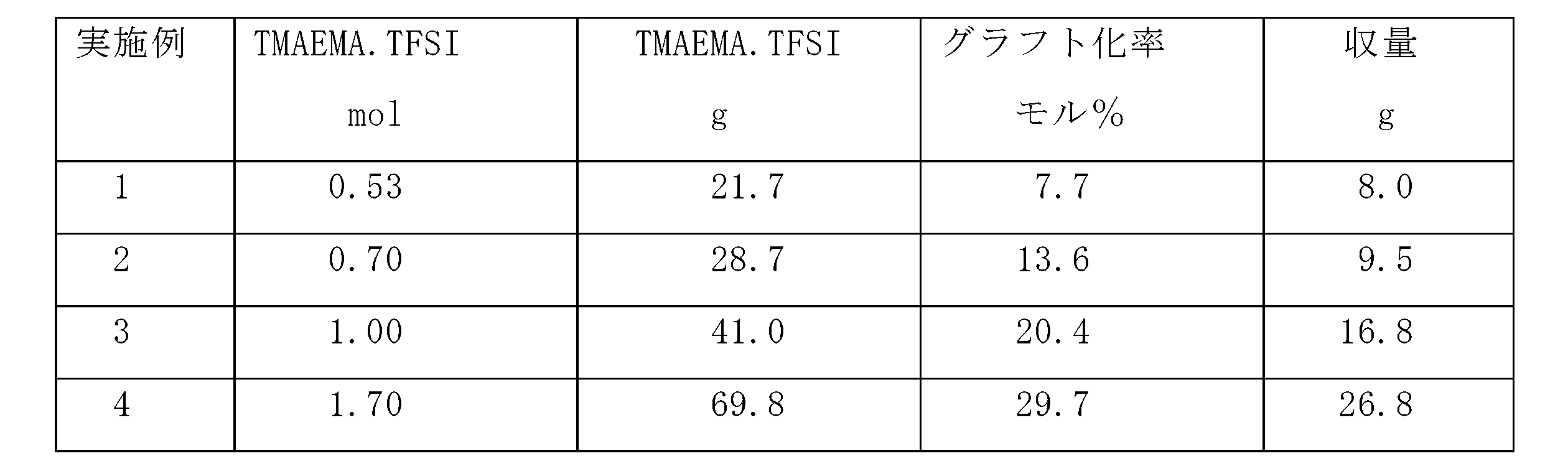
TMAEMA・TFSI 1molのときの使用量=452.2/66.1×6=41.0g
0.7molでは41×0.7=28.7gとなる。
注2)グラフト化率(モル%)
PVdF-CTFE共重合体とTMAEMA・TFSIの配合割合を変えて、赤外スペクト
ルを測定して検量線(図3)を作成した。横軸はTMAEMA・TFSIの配合割合
(モル%)、縦軸はスペクトルの吸光度強度比を示す。
この検量線を用いて、試料のTMAEMA・TFSIのグラフト化率(モル%)
を求めた。
PVdF-CTFE 881cm-1、TMAEMA・TFSI 1729cm-1 (C=O)を使用。
図1の各ピーク番号に対応する周波数(cm-1)及び透過率(%)は、表2のとおりである。


*1350-1352cm-1はアニオンの吸収ピークである。
*PVdF-CTFE共重合体(#7500)の吸収ピークは878-882cm-1付近にあり、グラフトPVdF(実施例3)ではこのピークが減少している。
以上の結果、PVdF-CTFE共重合体(#7500)及び実施例3のTMAEMA・TFSIグラフト重合体の二つのIRチャート(図1及び2)には前記の通り吸収ピークが示されており、これらの比較から、TMAEMA・TFSIが明確にグラフト化されていることが確認できた。
実施例3においてCTFE4モル%の共重合体の代わりにCTFE7モル%の共重合体である-(CH2-CF2)m-(CF2-CFCl)n-{mは93モル%、nは7モル%、呉羽化学工業社製、商品名 FD3145、固有粘度[η]=2.42(オストワルド粘度計使用、溶媒ジメチルアセトアミド(DMAC)、測定温度25℃)、[η]から推算分子量111万}を使用したこと、また、グラフト重合の条件として触媒CuClの代わりにCuBrを使用したこと以外は同様にしてグラフト重合した。結果を表4に示す。

(PVdF)m-(CTFE)n共重合体(mは93モル%、nは7モル%)のときの単量体
平均分子量67.7
実施例3において、TMAEMA・TFSIの代わりに、化合物名トリメチルアミノエチルメタクリレート・ヘキサフルオロホスフェート(TMAEMA・PF6)(合成例7)8943gを使用した以外は同様にしてグラフト重合した。結果を表5に示す。
実施例3において、TMAEMA・TFSIの代わりに、トリメチルアミノプロピルアクリルアミド{(トリフルオロメチル)スルフォニル}イミド(TMAPAA・TFSI)(合成例4)を61.5g使用する以外は同様にしてグラフト重合した。結果を表6に示す。

実施例3において、TMAEMA・TFSIの代わりに、トリメチルアミノエチルメタクリレート・ビス{(トリフルオロメチル)スルフォニル}イミド(TMAEA・TFSI)(合成例5)を39.8g使用する以外は同様にしてグラフト重合反応した。結果を表7に示す。
実施例3において、溶融塩単量体としてTMAEMA・TFSIの代わりにトリメチルアミノエチルメタクリレートビスフルオロスルフォニルイミド(TMAEMA・FSI)(合成例8)を34.7g使用する以外は同様にしてグラフト重合反応した。結果を表8に示す。

[比較例1-3]
実施例3のPVdF-CTFE共重合体(#7500)の代わりに、塩素を含まないフッ化ビニリデン重合体-(CH2-CF2)-{呉羽化学者製、商品名#1700(比較例1)、ソルベイ社製、商品名Kynar461(比較例2)}及びフッ化ビニリデン(PVdF)-ヘキサフロロプロピレン(HFP)共重合体(ソルベイ社製Kynar2801)(比較例3)を使用した。


〔η〕=2.01×10⁻⁴×Mw0.675
この式より Mw=(η/2.01×10-4)1/0.675
出典:Solubility Parameter of Polyvinylidenfluoride, Journal of
Polymer Science Part B Polymer Physics Vol26,785-794
新規複合電解質プリカーサー液の調製:
合成例1の通り、1-メチル-1-プロピルピペリジニウムビス{(トリフルオロメチル)スルフォニル}イミド(MPP・TFSI)を合成した。また、合成例2の通り、ジアリルジメチルアンモニウムビス{(トリフルオロメチル)スルフォニル}イミド〔DAA・TFSI〕を合成した。グラフト重合体として、実施例3の通り、トリメチルアミノエチルメタクリレートがグラフト重合したポリフッ素系重合体(TMAEMA-グラフト重合体)を合成した。
前記MPP・TFSI 2.4gにLi・TFSI(1.3mol相当)をドーピングした溶液を、前記TMAEMA-グラフト重合体5.0gをNMP295gに溶解したプレカーサーに溶解し、ホモジナイザーにて均一分散溶液となる様に攪拌して不燃性の新規複合電解質プリカーサー液を作製した。その後、反応基を保有する溶融塩単量体DAA・TFSI 1.6gを均一分散溶液に加えて、ホモジナイザー攪拌して不燃性の新規複合電解質プリカーサー液を作製した。
正極活物質であるLiCoO290重量%と導電剤であるアセチレンブラック5重量%とを、前記複合高分子電解質プリカーサー溶液5重量%に混合した正極合剤液を作製し、NMP溶剤を加えて50重量%固形分正極塗料にし、集電体であるアルミニウム箔に塗布し、70℃から100℃まで昇温し、更に130℃まで昇温し、合計45分間加熱して乾燥させて正電極を作製する。更に、正極片面層厚みが15μmになるようにプレスした。
負極活物質である天然グラファイト95重量%と導電剤であるケッチェンブラック2重量%とを前記複合高分子電解質プリカーサー溶液3重量%に混合した負極合剤液を作製し、NMP溶剤を加えて50重量%固形分負極塗料にし、集電体である銅箔に塗布し80℃から110℃まで昇温し、更に130℃まで昇温し、合計45分間加熱し乾燥させて負電極を作製した。更に、正極片面層厚みが20μmになるようにプレスした。
不燃性である前記複合高分子電解質プリカーサー溶液を100μmのポリエステルフィルム(東レ社製Tタイプ)にコーティングし、130で30分間加熱し乾燥させ、膜厚20μmの複合高分子電解質膜をポリエステルフィルム上に形成した。
充放電サイクル試験条件:充電は電流1mA、終止電圧4.0Vで定電流充電とした。放電は電流1mA、終止電圧2.5Vで定電流放電とした。
前記実施例10(実施例3のグラフト重合体を使用)において、実施例3のグラフト重合体の代わりに、実施例1~9(実施例3を除く)で作製されたグラフト重合体を使用して、同様に複合電解質膜及びセルを得た。このセルの試験結果(膜導電性能、イオン伝導性、不燃性、力学的強度:引っ張り強度等)を表11に示す。
前記実施例10(実施例3のグラフト重合体を使用)において、実施例3のグラフト重合体の代わりに、比較例1~3で作製されたグラフト重合体を使用して、同様に複合電解質膜及びセルを得た。このセルの試験結果も併せて表11に示す。

実施例11(実施例1のグラフト重合体を使用)
実施例12(実施例2のグラフト重合体を使用)
実施例13(実施例4のグラフト重合体を使用)
実施例14(実施例5のグラフト重合体を使用)
実施例15(実施例6のグラフト重合体を使用)
実施例16(実施例7のグラフト重合体を使用)
実施例17(実施例8のグラフト重合体を使用)
実施例18(実施例9のグラフト重合体を使用)
比較例4(比較例1のグラフト重合体を使用)
比較例5(比較例2のグラフト重合体を使用)
比較例6(比較例3のグラフト重合体を使用)
注2) 輸率(transport number):液間電位の輸率は、電池電位法により算出した。
注3) 膜導電性能: 電極面積0.95cm2の白金電極間に試料を挟み、20℃、65%RHで、交流インピーダンス法(0.1V、周波数1Hz~10MHz)により膜抵抗を測定し、膜導電性能を算出した。
注4) 引張強度:A&D社製、引張り試験機テンシロンRT1350を用い、23℃、5cm/min.で測定した。
試験装置: 電池安全性試験装置(株式会社美和製作所製)
(釘・針刺し試験、加熱圧壊試験等用装置)
針の仕様: 0.8mm径木綿針使用
刺込み速度: 1mm/秒
試験結果として、実施例及び比較例とも、発火・発煙は、認められず、不燃性を確認された。
Claims (20)
- 式:-(CR1R2-CFX)-
式中、Xは、フッ素以外のハロゲン原子であり、
R1及びR2は、水素原子又はフッ素原子であり、両者は同一
であってもよいし異なっていてもよい、
で示される単位を有する重合体に、4級アンモニウムカチオンとアニオンからなる4級アンモニウム塩構造を有し、かつ重合性官能基を有する溶融塩単量体をグラフト重合することを特徴とするフッ素系重合体の製法。 - -(CR1R2-CFX)-単位を有する重合体が、
式:-(CR3R4-CR5F)m-(CR1R2-CFX)n
式中、Xは、フッ素以外のハロゲン原子であり、
R1、R2、R3、R4及びR5は、水素原子又はフッ素原子であ
り、これらは同一であってもよいし異なっていてもよく、
mは99~65モル%であり、
nは1~35モル%である、
で示される共重合体である請求項1記載のフッ素系重合体の製法。 - -(CR1R2-CFX)-単位を有する重合体が、
式:-(CH2-CF2)m-(CF2-CFCl)n-
式中、mは99~65モル%であり、
nは1~35モル%である、
で示される共重合体である請求項2記載のフッ素系重合体の製法。 - 原子移動ラジカル重合で、-(CR1R2-CFX)-単位を有する重合体のフッ素以外のハロゲン原子を引き抜き、溶融塩単量体をグラフト重合する請求項1~3のいずれか1項記載のフッ素系重合体の製法。
- 溶融塩単量体が、-(CR1R2-CFX)-単位を有する重合体に3~40モル%グラフト重合している請求項1~4のいずれか1項記載のフッ素系重合体の製法。
- 溶融塩単量体が、(A)トリアルキルアミノエチルメタクリレートアンモニウムカチオン、トリアルキルアミノエチルアクリレートアンモニウムカチオン、トリアルキルアミノプロピルアクリルアミドアンモニウムカチオン、1-アルキル-3-ビニルイミダゾリウムカチオン、4-ビニル-1-アルキルピリジニウムカチオン、1-(4-ビニルベンジル)-3-アルキルイミダゾリウムカチオン、1-(ビニルオキシエチル)-3-アルキルイミダゾリウムカチオン、1-ビニルイミダゾリウムカチオン、1-アリルイミダゾリウムカチオン、N-アルキル-N-アリルアンモニウムカチオン、1-ビニル-3-アルキルイミダゾリウムカチオン、1-ビニル-3-アルキルイミダゾリウムカチオン、1-グリシジル-3-アルキル-イミダゾリウムカチオン、N-アリル-N-アルキルピロリジニウムカチオン及び4級ジアリルジアルキルアンモニウムカチオンからなる群から選ばれた4級アンモニウムカチオンと、(B)ビス{(トリフルオロメチル)スルフォニル}イミドアニオン、2,2,2-トリフルオロ-N-{(トリフルオロメチル)スルフォニル)}アセトイミドアニオン、ビス{(ペンタフルオロエチル)スルフォニル}イミドアニオン、ビス{(フルオロ)スルフォニル}イミドアニオン、テトラフルオロボレートアニオン、ヘキサフロオロフォスヘートアニオン及びトリフルオロメタンスルフォニルイミドアニオンからなる群から選ばれたアニオンとの塩である請求項1~5のいずれか1項記載のフッ素系重合体の製法。
- 4級アンモニウムカチオンとアニオンからなる4級アンモニウム塩構造を有し、かつ重合性官能基を有する溶融塩単量体を含む単量体組成物を、
式:-(CR1R2-CFX)-
式中、Xは、フッ素以外のハロゲン原子であり、
R1及びR2は、水素原子又はフッ素原子であり、両者は同一であってもよいし
異なっていてもよい、
で示される単位を有する重合体に配合し、前記溶融塩単量体を前記重合体にグラフト重合して得られたフッ素系重合体を含む、複合高分子電解質組成物。 - -(CR1R2-CFX)-単位を有する重合体が、
式:-(CR3R4-CR5F)m-(CR1R2-CFX)n
式中、Xは、フッ素以外のハロゲン原子であり、
R1、R2、R3、R4及びR5は、水素原子又はフッ素原子であ
り、これらは同一であってもよいし異なっていてもよく、
mは99~65モル%であり、
nは1~35モル%である、
で示される共重合体である請求項7記載の複合高分子電解質組成物。 - 溶融塩単量体、-(CR1R2-CFX)-単位を有する重合体に3~40モル%グラフト重合している請求項7又は8記載の複合高分子電解質組成物。
- フッ素系重合体とグラフト重合体が、分子レベルで積層された重層構造体(ラメラ構造)を形成している請求項7記載の複合高分子電解質組成物。
- 溶融塩単量体が、(A)トリアルキルアミノエチルメタクリレートアンモニウムカチオン、トリアルキルアミノエチルアクリレートアンモニウムカチオン、トリアルキルアミノプロピルアクリルアミドアンモニウムカチオン、1-アルキル-3-ビニルイミダゾリウムカチオン、4-ビニル-1-アルキルピリジニウムカチオン、1-(4-ビニルベンジル)-3-アルキルイミダゾリウムカチオン、1-(ビニルオキシエチル)-3-アルキルイミダゾリウムカチオン、1-ビニルイミダゾリウムカチオン、1-アリルイミダゾリウムカチオン、N-アルキル-N-アリルアンモニウムカチオン、1-ビニル-3-アルキルイミダゾリウムカチオン、1-ビニル-3-アルキルイミダゾリウムカチオン、1-グリシジル-3-アルキル-イミダゾリウムカチオン、N-アリル-N-アルキルピロリジニウムカチオン及び4級ジアリルジアルキルアンモニウムカチオンからなる群から選ばれた4級アンモニウムカチオンと(B)ビス{(トリフルオロメチル)スルフォニル}イミドアニオン、2,2,2-トリフルオロ-N-{(トリフルオロメチル)スルフォニル)}アセトイミドアニオン、ビス{(ペンタフルオロエチル)スルフォニル}イミドアニオン、ビス{(フルオロ)スルフォニル}イミドアニオン、テトラフルオロボレートアニオン、ヘキサフロオロフォスヘートアニオン、トリフルオロメタンスルフォニルイミドアニオンからなる群から選ばれたアニオンとの塩である請求項7~10のいずれか1項記載の複合高分子電解質組成物。
- 単量体組成物が電荷移動イオン源を含んでいる請求項7~11のいずれか1項記載の複合高分子電解質組成物。
- イオン源が、LiBF4、LiPF6、CnF2n+1CO2Li(但しnは1~4の整数)、CnF2n+1SO3Li(但しnは1~4の整数)、(FSO2)2NLi、(CF3SO2)2NLi、(C2F5SO2)2NLi、(CF3SO2)3CLi、(CF3-SO2-N-COCF3)Li、及び(R-SO2-N-SO2CF3)Li(Rは脂肪族基又は芳香族基)からなる群から選ばれたリチウム塩である請求項12記載の複合高分子電解質組成物。
- 対向する負極と正極の間に配置されている請求項13記載の複合高分子電解質組成物を備えているリチウムイオン電池又はリチウムイオンキャパシタ。
- イオン源が、HBF4、HPF6、CnF2n+1CO2H(nは1~4の整数)、CnF2n+1SO3H(nは1~4の整数)、(FSO2)NH、(CF3SO2)NH、(C2F5SO2)NH、(CF3SO2)3NH、(CF3-SO2-NH-COCF3)、及び(R-SO2-NH-SO2CF3)(Rは脂肪族基又は芳香族基)からなる群から選ばれたプロトン供与体である請求項12記載の複合高分子電解質組成物。
- 対向する負極と正極の間に配置された請求項15記載の複合高分子電解質組成物を備えているPEM燃料セル電池。
- イオン源が、I3 -/I-又はBr3 -/Br-レドックスイオン対である請求項12記載の複合高分子電解質組成物。
- 色素を吸着させた酸化物半導体膜を有する作用極と、導電性対極の間に配置された請求項17記載の複合高分子電解質組成物を備えている色素増感太陽電池。
- 対抗する導電性電極間に配置された電子輸送層と有機材料を含む発光層に請求項13又は17記載の複合高分子電解質組成物を備えている有機ELセル。
- 対向する導電性電極間に配置された電荷移動イオン源を含まない請求項7記載の複合高分子電解質組成物を備えている電解コンデンサ・キャパシタ。
Priority Applications (4)
| Application Number | Priority Date | Filing Date | Title |
|---|---|---|---|
| EP10758742.0A EP2415793B1 (en) | 2009-03-30 | 2010-03-30 | Method of producing fluorinated polymer |
| US13/260,928 US9562126B2 (en) | 2009-03-30 | 2010-03-30 | Process for producing fluorine containing polymer |
| JP2011507231A JP5688527B2 (ja) | 2009-03-30 | 2010-03-30 | フッ素系重合体の製法 |
| US15/174,646 US9979037B2 (en) | 2009-03-30 | 2016-06-06 | Process for producing fluorine containing polymer |
Applications Claiming Priority (2)
| Application Number | Priority Date | Filing Date | Title |
|---|---|---|---|
| JP2009083676 | 2009-03-30 | ||
| JP2009-083676 | 2009-03-30 |
Related Child Applications (2)
| Application Number | Title | Priority Date | Filing Date |
|---|---|---|---|
| US13/260,928 A-371-Of-International US9562126B2 (en) | 2009-03-30 | 2010-03-30 | Process for producing fluorine containing polymer |
| US15/174,646 Division US9979037B2 (en) | 2009-03-30 | 2016-06-06 | Process for producing fluorine containing polymer |
Publications (1)
| Publication Number | Publication Date |
|---|---|
| WO2010113971A1 true WO2010113971A1 (ja) | 2010-10-07 |
Family
ID=42828260
Family Applications (1)
| Application Number | Title | Priority Date | Filing Date |
|---|---|---|---|
| PCT/JP2010/055752 WO2010113971A1 (ja) | 2009-03-30 | 2010-03-30 | フッ素系重合体の製法 |
Country Status (5)
| Country | Link |
|---|---|
| US (2) | US9562126B2 (ja) |
| EP (1) | EP2415793B1 (ja) |
| JP (1) | JP5688527B2 (ja) |
| KR (1) | KR101647170B1 (ja) |
| WO (1) | WO2010113971A1 (ja) |
Cited By (14)
| Publication number | Priority date | Publication date | Assignee | Title |
|---|---|---|---|---|
| JP2012142196A (ja) * | 2010-12-28 | 2012-07-26 | Sekisui Chem Co Ltd | 多価イオン伝導性材料、多価イオン伝導性電解質、多価イオン伝導性電解質−電極接合体、及び多価イオン電池 |
| JP2013185088A (ja) * | 2012-03-08 | 2013-09-19 | Daicel Corp | 樹脂組成物及びその硬化物、並びに発光素子 |
| JP2014514698A (ja) * | 2011-03-28 | 2014-06-19 | ポステック アカデミー‐インダストリー ファウンデーション | 高分子で置換されたシリコンナノ粒子と自己組織化ブロック共重合体を含む高性能リチウム−ポリマー電池 |
| JP2015038870A (ja) * | 2013-07-19 | 2015-02-26 | パイオトレック株式会社 | 正極および/または負極に使用する導電性を有する結合剤 |
| WO2015151525A1 (ja) * | 2014-04-02 | 2015-10-08 | 日本ゼオン株式会社 | 二次電池電極用バインダー組成物、二次電池電極用スラリー組成物、二次電池用電極、および、二次電池 |
| WO2016063994A1 (ja) * | 2014-10-22 | 2016-04-28 | パイオトレック株式会社 | 導電素材および積層体 |
| WO2017126701A1 (ja) * | 2016-01-19 | 2017-07-27 | パイオトレック株式会社 | 高効率イオン電導型リチウムイオン電池またはリチウムイオンキャパシタ |
| WO2018043760A3 (ja) * | 2016-09-05 | 2018-05-03 | パイオトレック株式会社 | 導電素材およびその用途 |
| JP2019081884A (ja) * | 2017-10-31 | 2019-05-30 | 株式会社イーテック | 組成物 |
| WO2019146137A1 (ja) | 2018-01-24 | 2019-08-01 | パイオトレック株式会社 | セパレーターレス導電ポリマー固体電解質二次電池 |
| JP2019525971A (ja) * | 2016-06-20 | 2019-09-12 | ソルヴェイ(ソシエテ アノニム) | フルオロポリマーフィルム |
| JPWO2018193683A1 (ja) * | 2017-04-21 | 2020-02-27 | 日立化成株式会社 | 電気化学デバイス用部材及び電気化学デバイス |
| WO2021025521A1 (ko) * | 2019-08-08 | 2021-02-11 | 주식회사 엘지화학 | 고분자 전해질용 공중합체, 이를 포함하는 겔 폴리머 전해질 및 리튬 이차전지 |
| CN114644765A (zh) * | 2022-03-09 | 2022-06-21 | 中国科学院上海硅酸盐研究所 | 一种复合离子水凝胶组合物及其制备方法与应用 |
Families Citing this family (19)
| Publication number | Priority date | Publication date | Assignee | Title |
|---|---|---|---|---|
| CN103360524A (zh) * | 2012-04-09 | 2013-10-23 | 纳幕尔杜邦公司 | 两相反应介质中的氟化乙烯基单体的聚合 |
| CN103456506A (zh) * | 2012-05-31 | 2013-12-18 | 海洋王照明科技股份有限公司 | 一种聚丙烯腈基凝胶聚合物电解质电容器的制备方法 |
| US8928966B1 (en) * | 2012-08-08 | 2015-01-06 | Gentex Corporation | Electrochromic polyelectrolyte gel medium having improved creep resistance and associated electrochromic device |
| CN103833675B (zh) * | 2012-11-26 | 2016-04-27 | 海洋王照明科技股份有限公司 | 哌啶类离子液体及其制备方法和应用 |
| EP3132471A4 (en) * | 2014-04-16 | 2017-11-22 | The Board of Trustees of The Leland Stanford Junior University | Polar elastomers for high performance electronic and optoelectronic devices |
| WO2016160703A1 (en) | 2015-03-27 | 2016-10-06 | Harrup Mason K | All-inorganic solvents for electrolytes |
| WO2017173323A1 (en) | 2016-04-01 | 2017-10-05 | NOHMs Technologies, Inc. | Modified ionic liquids containing phosphorus |
| JP7031890B2 (ja) | 2016-07-28 | 2022-03-08 | イクシオン ラブス インコーポレイテッド | ポリマーベースの抗菌性組成物及びその使用方法 |
| US10707531B1 (en) | 2016-09-27 | 2020-07-07 | New Dominion Enterprises Inc. | All-inorganic solvents for electrolytes |
| TWI794224B (zh) * | 2017-04-21 | 2023-03-01 | 南韓商Lg新能源股份有限公司 | 電化學裝置用電極及其製造方法、電化學裝置、以及聚合物電解質組成物 |
| JP6973477B2 (ja) | 2017-04-21 | 2021-12-01 | 昭和電工マテリアルズ株式会社 | ポリマ電解質組成物及びポリマ二次電池 |
| CN110915037B (zh) | 2017-07-17 | 2023-11-07 | 诺姆斯科技公司 | 含磷电解质 |
| CN107860810B (zh) * | 2017-10-20 | 2021-01-29 | 合肥国轩高科动力能源有限公司 | 一种表征sei膜的形成和分解过程的电化学方法及系统 |
| US11655402B2 (en) | 2017-11-21 | 2023-05-23 | Nitto Denko Corporation | Basic ionic liquids compositions and elements including the same |
| WO2020022620A1 (ko) * | 2018-07-27 | 2020-01-30 | 주식회사 엘지화학 | 전극 보호층용 고분자 및 이를 적용한 이차전지 |
| CN109627227B (zh) * | 2018-12-14 | 2020-07-17 | 浙江工业大学 | 一种哌啶型离子液体及其制备方法与应用 |
| US11267707B2 (en) | 2019-04-16 | 2022-03-08 | Honeywell International Inc | Purification of bis(fluorosulfonyl) imide |
| KR102400671B1 (ko) * | 2019-10-30 | 2022-05-23 | 한국화학연구원 | 불소계 공중합체에 양이온성 단량체가 그라프트 중합된 고분자 화합물을 포함하는 항균성 고분자 조성물 |
| KR20230153627A (ko) * | 2022-04-29 | 2023-11-07 | 한국화학연구원 | 불소계 공중합체에 양이온성 단량체와 불소계 아크릴 단량체가 그라프트 중합된 고분자 화합물을 포함하는 항균성 고분자 조성물 |
Citations (10)
| Publication number | Priority date | Publication date | Assignee | Title |
|---|---|---|---|---|
| JPS5032289A (ja) * | 1973-07-21 | 1975-03-28 | ||
| JPH1083821A (ja) | 1996-07-17 | 1998-03-31 | Shikoku Chem Corp | 溶融塩型高分子電解質 |
| JPH1092467A (ja) | 1996-09-18 | 1998-04-10 | Toshiba Corp | 非水電解液二次電池 |
| JPH10265674A (ja) | 1997-03-25 | 1998-10-06 | Mitsubishi Chem Corp | 高分子化合物複合体及びその製造方法 |
| JPH1192467A (ja) | 1997-09-18 | 1999-04-06 | Toray Ind Inc | エポキシ化合物の安定化法と安定剤および重合劣化しにくいエポキシ化合物 |
| JP2000011753A (ja) | 1998-06-17 | 2000-01-14 | Shikoku Chem Corp | イミダゾリウム系溶融塩型電解質 |
| JP2002042870A (ja) | 2000-07-27 | 2002-02-08 | Trekion Co Ltd | ポリマー電解質を使った二次電池 |
| WO2004088671A1 (ja) | 2003-03-31 | 2004-10-14 | Trekion Co., Ltd. | 複合高分子電解質組成物 |
| WO2006046620A1 (ja) * | 2004-10-27 | 2006-05-04 | Asahi Glass Company, Limited | 電解質材料、電解質膜、及び固体高分子形燃料電池用膜電極接合体 |
| JP2007157428A (ja) * | 2005-12-02 | 2007-06-21 | Nitto Denko Corp | 高分子電解質膜及びその製造方法 |
Family Cites Families (3)
| Publication number | Priority date | Publication date | Assignee | Title |
|---|---|---|---|---|
| US3624053A (en) * | 1963-06-24 | 1971-11-30 | Du Pont | Trifluorovinyl sulfonic acid polymers |
| JP3817045B2 (ja) * | 1997-09-12 | 2006-08-30 | 四国化成工業株式会社 | 溶融塩型高分子電解質 |
| DE102005013790B4 (de) * | 2005-03-24 | 2007-03-29 | Polymaterials Ag | Polymerelektrolyt, Verwendung des Polymerelektrolyten und elektrochemische Vorrichtung, die den Polymerelektrolyten umfasst |
-
2010
- 2010-03-30 US US13/260,928 patent/US9562126B2/en active Active
- 2010-03-30 EP EP10758742.0A patent/EP2415793B1/en active Active
- 2010-03-30 WO PCT/JP2010/055752 patent/WO2010113971A1/ja active Application Filing
- 2010-03-30 JP JP2011507231A patent/JP5688527B2/ja active Active
- 2010-03-30 KR KR1020117025494A patent/KR101647170B1/ko active IP Right Grant
-
2016
- 2016-06-06 US US15/174,646 patent/US9979037B2/en active Active
Patent Citations (10)
| Publication number | Priority date | Publication date | Assignee | Title |
|---|---|---|---|---|
| JPS5032289A (ja) * | 1973-07-21 | 1975-03-28 | ||
| JPH1083821A (ja) | 1996-07-17 | 1998-03-31 | Shikoku Chem Corp | 溶融塩型高分子電解質 |
| JPH1092467A (ja) | 1996-09-18 | 1998-04-10 | Toshiba Corp | 非水電解液二次電池 |
| JPH10265674A (ja) | 1997-03-25 | 1998-10-06 | Mitsubishi Chem Corp | 高分子化合物複合体及びその製造方法 |
| JPH1192467A (ja) | 1997-09-18 | 1999-04-06 | Toray Ind Inc | エポキシ化合物の安定化法と安定剤および重合劣化しにくいエポキシ化合物 |
| JP2000011753A (ja) | 1998-06-17 | 2000-01-14 | Shikoku Chem Corp | イミダゾリウム系溶融塩型電解質 |
| JP2002042870A (ja) | 2000-07-27 | 2002-02-08 | Trekion Co Ltd | ポリマー電解質を使った二次電池 |
| WO2004088671A1 (ja) | 2003-03-31 | 2004-10-14 | Trekion Co., Ltd. | 複合高分子電解質組成物 |
| WO2006046620A1 (ja) * | 2004-10-27 | 2006-05-04 | Asahi Glass Company, Limited | 電解質材料、電解質膜、及び固体高分子形燃料電池用膜電極接合体 |
| JP2007157428A (ja) * | 2005-12-02 | 2007-06-21 | Nitto Denko Corp | 高分子電解質膜及びその製造方法 |
Non-Patent Citations (2)
| Title |
|---|
| "Solubility Parameter of Polyvinylidene fluoride", JOURNAL OF POLYMER SCIENCE PART B POLYMER PHYSICS, vol. 26, pages 785 - 794 |
| See also references of EP2415793A4 |
Cited By (29)
| Publication number | Priority date | Publication date | Assignee | Title |
|---|---|---|---|---|
| JP2012142196A (ja) * | 2010-12-28 | 2012-07-26 | Sekisui Chem Co Ltd | 多価イオン伝導性材料、多価イオン伝導性電解質、多価イオン伝導性電解質−電極接合体、及び多価イオン電池 |
| JP2014514698A (ja) * | 2011-03-28 | 2014-06-19 | ポステック アカデミー‐インダストリー ファウンデーション | 高分子で置換されたシリコンナノ粒子と自己組織化ブロック共重合体を含む高性能リチウム−ポリマー電池 |
| JP2013185088A (ja) * | 2012-03-08 | 2013-09-19 | Daicel Corp | 樹脂組成物及びその硬化物、並びに発光素子 |
| JP2015038870A (ja) * | 2013-07-19 | 2015-02-26 | パイオトレック株式会社 | 正極および/または負極に使用する導電性を有する結合剤 |
| WO2015151525A1 (ja) * | 2014-04-02 | 2015-10-08 | 日本ゼオン株式会社 | 二次電池電極用バインダー組成物、二次電池電極用スラリー組成物、二次電池用電極、および、二次電池 |
| KR20160138961A (ko) * | 2014-04-02 | 2016-12-06 | 니폰 제온 가부시키가이샤 | 이차전지전극용 바인더 조성물, 이차전지전극용 슬러리 조성물, 이차전지용 전극, 및 이차전지 |
| JPWO2015151525A1 (ja) * | 2014-04-02 | 2017-04-13 | 日本ゼオン株式会社 | 二次電池電極用バインダー組成物、二次電池電極用スラリー組成物、二次電池用電極、および、二次電池 |
| KR102240708B1 (ko) | 2014-04-02 | 2021-04-14 | 니폰 제온 가부시키가이샤 | 이차전지전극용 바인더 조성물, 이차전지전극용 슬러리 조성물, 이차전지용 전극, 및 이차전지 |
| WO2016063994A1 (ja) * | 2014-10-22 | 2016-04-28 | パイオトレック株式会社 | 導電素材および積層体 |
| WO2017126701A1 (ja) * | 2016-01-19 | 2017-07-27 | パイオトレック株式会社 | 高効率イオン電導型リチウムイオン電池またはリチウムイオンキャパシタ |
| JPWO2017126701A1 (ja) * | 2016-01-19 | 2019-01-24 | パイオトレック株式会社 | 高効率イオン電導型リチウムイオン電池またはリチウムイオンキャパシタ |
| JP2019525971A (ja) * | 2016-06-20 | 2019-09-12 | ソルヴェイ(ソシエテ アノニム) | フルオロポリマーフィルム |
| JP7416564B2 (ja) | 2016-06-20 | 2024-01-17 | ソルヴェイ(ソシエテ アノニム) | フルオロポリマーフィルム |
| JP2022115942A (ja) * | 2016-06-20 | 2022-08-09 | ソルヴェイ(ソシエテ アノニム) | フルオロポリマーフィルム |
| WO2018043760A3 (ja) * | 2016-09-05 | 2018-05-03 | パイオトレック株式会社 | 導電素材およびその用途 |
| JPWO2018043760A1 (ja) * | 2016-09-05 | 2019-07-11 | パイオトレック株式会社 | 導電素材およびその用途 |
| JP7018555B2 (ja) | 2016-09-05 | 2022-02-14 | パイオトレック株式会社 | 導電素材およびその用途 |
| JPWO2018193683A1 (ja) * | 2017-04-21 | 2020-02-27 | 日立化成株式会社 | 電気化学デバイス用部材及び電気化学デバイス |
| JP2019081884A (ja) * | 2017-10-31 | 2019-05-30 | 株式会社イーテック | 組成物 |
| KR20200104891A (ko) | 2018-01-24 | 2020-09-04 | 파이오트렉쿠 가부시키가이샤 | 세퍼레이터리스 도전 폴리머 고체 전해질 이차 전지 |
| JPWO2019146137A1 (ja) * | 2018-01-24 | 2021-01-28 | パイオトレック株式会社 | セパレーターレス導電ポリマー固体電解質二次電池 |
| JP7285419B2 (ja) | 2018-01-24 | 2023-06-02 | パイオトレック株式会社 | セパレーターレス導電ポリマー固体電解質二次電池 |
| US11735763B2 (en) | 2018-01-24 | 2023-08-22 | Piotrek Co., Ltd. | Solid state electrolyte rechargeable battery in no use of separator |
| WO2019146137A1 (ja) | 2018-01-24 | 2019-08-01 | パイオトレック株式会社 | セパレーターレス導電ポリマー固体電解質二次電池 |
| WO2021025521A1 (ko) * | 2019-08-08 | 2021-02-11 | 주식회사 엘지화학 | 고분자 전해질용 공중합체, 이를 포함하는 겔 폴리머 전해질 및 리튬 이차전지 |
| JP2022534952A (ja) * | 2019-08-08 | 2022-08-04 | エルジー エナジー ソリューション リミテッド | 高分子電解質用共重合体、これを含むゲルポリマー電解質及びリチウム二次電池 |
| JP7317432B2 (ja) | 2019-08-08 | 2023-07-31 | エルジー エナジー ソリューション リミテッド | 高分子電解質用共重合体、これを含むゲルポリマー電解質及びリチウム二次電池 |
| CN114644765A (zh) * | 2022-03-09 | 2022-06-21 | 中国科学院上海硅酸盐研究所 | 一种复合离子水凝胶组合物及其制备方法与应用 |
| CN114644765B (zh) * | 2022-03-09 | 2023-12-08 | 中国科学院上海硅酸盐研究所 | 一种复合离子水凝胶组合物及其制备方法与应用 |
Also Published As
| Publication number | Publication date |
|---|---|
| JP5688527B2 (ja) | 2015-03-25 |
| EP2415793B1 (en) | 2015-01-14 |
| US20170040632A1 (en) | 2017-02-09 |
| KR20120027176A (ko) | 2012-03-21 |
| JPWO2010113971A1 (ja) | 2012-10-11 |
| EP2415793A1 (en) | 2012-02-08 |
| US9562126B2 (en) | 2017-02-07 |
| EP2415793A4 (en) | 2014-01-01 |
| US9979037B2 (en) | 2018-05-22 |
| US20120107726A1 (en) | 2012-05-03 |
| KR101647170B1 (ko) | 2016-08-09 |
Similar Documents
| Publication | Publication Date | Title |
|---|---|---|
| JP5688527B2 (ja) | フッ素系重合体の製法 | |
| KR102303831B1 (ko) | 고분자, 이를 포함하는 전해질 및 리튬이차전지 | |
| US7732099B2 (en) | Composite polymer electrolyte composition | |
| US9991057B2 (en) | Hybrid fluoropolymer composition | |
| JP6410021B2 (ja) | 正極および/または負極に使用する導電性を有する結合剤 | |
| WO2003028144A1 (en) | Element using polymer gel electrolyte | |
| CN107924769A (zh) | 凝胶电解质用组合物 | |
| JP7359137B2 (ja) | 蓄電デバイス用セパレータ、蓄電デバイスおよびそれらの製造方法 | |
| JP6875620B2 (ja) | 高効率イオン電導型リチウムイオン電池またはリチウムイオンキャパシタ | |
| JP2013175701A (ja) | 電気化学キャパシタ | |
| JP2003187637A (ja) | 高分子ゲル電解質を用いた素子 | |
| JP2007122902A (ja) | リチウムイオン電池の製造方法 | |
| WO2016159083A1 (ja) | 電気化学キャパシタ | |
| JP2015028905A (ja) | 非水電解質二次電池 | |
| JP6971844B2 (ja) | 電気化学キャパシタ | |
| JP5915967B2 (ja) | 蓄電デバイス用セパレータ、蓄電デバイスおよびそれらの製造方法 | |
| JP2016091668A (ja) | 有機二次電池 | |
| KR20230163349A (ko) | 음극 보호막 | |
| JP2022062997A (ja) | 蓄電デバイス用正極、蓄電デバイス用正極の製造方法および蓄電デバイス | |
| JP2020167114A (ja) | 電極用スラリー組成物、電極、及び蓄電デバイス |
Legal Events
| Date | Code | Title | Description |
|---|---|---|---|
| 121 | Ep: the epo has been informed by wipo that ep was designated in this application |
Ref document number: 10758742 Country of ref document: EP Kind code of ref document: A1 |
|
| WWE | Wipo information: entry into national phase |
Ref document number: 2011507231 Country of ref document: JP |
|
| NENP | Non-entry into the national phase |
Ref country code: DE |
|
| WWE | Wipo information: entry into national phase |
Ref document number: 4228/KOLNP/2011 Country of ref document: IN |
|
| ENP | Entry into the national phase |
Ref document number: 20117025494 Country of ref document: KR Kind code of ref document: A |
|
| WWE | Wipo information: entry into national phase |
Ref document number: 2010758742 Country of ref document: EP |
|
| WWE | Wipo information: entry into national phase |
Ref document number: 13260928 Country of ref document: US |