WO2010113792A1 - エッチング液の処理装置及び処理方法 - Google Patents
エッチング液の処理装置及び処理方法 Download PDFInfo
- Publication number
- WO2010113792A1 WO2010113792A1 PCT/JP2010/055357 JP2010055357W WO2010113792A1 WO 2010113792 A1 WO2010113792 A1 WO 2010113792A1 JP 2010055357 W JP2010055357 W JP 2010055357W WO 2010113792 A1 WO2010113792 A1 WO 2010113792A1
- Authority
- WO
- WIPO (PCT)
- Prior art keywords
- membrane
- etching solution
- etching
- processing apparatus
- concentration
- Prior art date
- Legal status (The legal status is an assumption and is not a legal conclusion. Google has not performed a legal analysis and makes no representation as to the accuracy of the status listed.)
- Ceased
Links
Images


Classifications
-
- H—ELECTRICITY
- H10—SEMICONDUCTOR DEVICES; ELECTRIC SOLID-STATE DEVICES NOT OTHERWISE PROVIDED FOR
- H10P—GENERIC PROCESSES OR APPARATUS FOR THE MANUFACTURE OR TREATMENT OF DEVICES COVERED BY CLASS H10
- H10P72/00—Handling or holding of wafers, substrates or devices during manufacture or treatment thereof
- H10P72/04—Apparatus for manufacture or treatment
- H10P72/0402—Apparatus for fluid treatment
- H10P72/0418—Apparatus for fluid treatment for etching
- H10P72/0422—Apparatus for fluid treatment for etching for wet etching
-
- H—ELECTRICITY
- H10—SEMICONDUCTOR DEVICES; ELECTRIC SOLID-STATE DEVICES NOT OTHERWISE PROVIDED FOR
- H10P—GENERIC PROCESSES OR APPARATUS FOR THE MANUFACTURE OR TREATMENT OF DEVICES COVERED BY CLASS H10
- H10P50/00—Etching of wafers, substrates or parts of devices
- H10P50/60—Wet etching
- H10P50/64—Wet etching of semiconductor materials
- H10P50/642—Chemical etching
-
- B—PERFORMING OPERATIONS; TRANSPORTING
- B01—PHYSICAL OR CHEMICAL PROCESSES OR APPARATUS IN GENERAL
- B01D—SEPARATION
- B01D61/00—Processes of separation using semi-permeable membranes, e.g. dialysis, osmosis or ultrafiltration; Apparatus, accessories or auxiliary operations specially adapted therefor
- B01D61/02—Reverse osmosis; Hyperfiltration ; Nanofiltration
- B01D61/027—Nanofiltration
-
- B—PERFORMING OPERATIONS; TRANSPORTING
- B01—PHYSICAL OR CHEMICAL PROCESSES OR APPARATUS IN GENERAL
- B01D—SEPARATION
- B01D61/00—Processes of separation using semi-permeable membranes, e.g. dialysis, osmosis or ultrafiltration; Apparatus, accessories or auxiliary operations specially adapted therefor
- B01D61/02—Reverse osmosis; Hyperfiltration ; Nanofiltration
- B01D61/12—Controlling or regulating
-
- B—PERFORMING OPERATIONS; TRANSPORTING
- B01—PHYSICAL OR CHEMICAL PROCESSES OR APPARATUS IN GENERAL
- B01D—SEPARATION
- B01D61/00—Processes of separation using semi-permeable membranes, e.g. dialysis, osmosis or ultrafiltration; Apparatus, accessories or auxiliary operations specially adapted therefor
- B01D61/14—Ultrafiltration; Microfiltration
- B01D61/145—Ultrafiltration
-
- B—PERFORMING OPERATIONS; TRANSPORTING
- B01—PHYSICAL OR CHEMICAL PROCESSES OR APPARATUS IN GENERAL
- B01D—SEPARATION
- B01D61/00—Processes of separation using semi-permeable membranes, e.g. dialysis, osmosis or ultrafiltration; Apparatus, accessories or auxiliary operations specially adapted therefor
- B01D61/14—Ultrafiltration; Microfiltration
- B01D61/22—Controlling or regulating
-
- B—PERFORMING OPERATIONS; TRANSPORTING
- B01—PHYSICAL OR CHEMICAL PROCESSES OR APPARATUS IN GENERAL
- B01D—SEPARATION
- B01D61/00—Processes of separation using semi-permeable membranes, e.g. dialysis, osmosis or ultrafiltration; Apparatus, accessories or auxiliary operations specially adapted therefor
- B01D61/58—Multistep processes
-
- C—CHEMISTRY; METALLURGY
- C02—TREATMENT OF WATER, WASTE WATER, SEWAGE, OR SLUDGE
- C02F—TREATMENT OF WATER, WASTE WATER, SEWAGE, OR SLUDGE
- C02F1/00—Treatment of water, waste water, or sewage
- C02F1/66—Treatment of water, waste water, or sewage by neutralisation; pH adjustment
-
- C—CHEMISTRY; METALLURGY
- C02—TREATMENT OF WATER, WASTE WATER, SEWAGE, OR SLUDGE
- C02F—TREATMENT OF WATER, WASTE WATER, SEWAGE, OR SLUDGE
- C02F11/00—Treatment of sludge; Devices therefor
- C02F11/12—Treatment of sludge; Devices therefor by de-watering, drying or thickening
- C02F11/14—Treatment of sludge; Devices therefor by de-watering, drying or thickening with addition of chemical agents
- C02F11/148—Combined use of inorganic and organic substances, being added in the same treatment step
-
- H—ELECTRICITY
- H10—SEMICONDUCTOR DEVICES; ELECTRIC SOLID-STATE DEVICES NOT OTHERWISE PROVIDED FOR
- H10F—INORGANIC SEMICONDUCTOR DEVICES SENSITIVE TO INFRARED RADIATION, LIGHT, ELECTROMAGNETIC RADIATION OF SHORTER WAVELENGTH OR CORPUSCULAR RADIATION
- H10F77/00—Constructional details of devices covered by this subclass
- H10F77/70—Surface textures, e.g. pyramid structures
-
- B—PERFORMING OPERATIONS; TRANSPORTING
- B01—PHYSICAL OR CHEMICAL PROCESSES OR APPARATUS IN GENERAL
- B01D—SEPARATION
- B01D2311/00—Details relating to membrane separation process operations and control
- B01D2311/06—Specific process operations in the permeate stream
-
- C—CHEMISTRY; METALLURGY
- C02—TREATMENT OF WATER, WASTE WATER, SEWAGE, OR SLUDGE
- C02F—TREATMENT OF WATER, WASTE WATER, SEWAGE, OR SLUDGE
- C02F1/00—Treatment of water, waste water, or sewage
- C02F1/52—Treatment of water, waste water, or sewage by flocculation or precipitation of suspended impurities
-
- C—CHEMISTRY; METALLURGY
- C02—TREATMENT OF WATER, WASTE WATER, SEWAGE, OR SLUDGE
- C02F—TREATMENT OF WATER, WASTE WATER, SEWAGE, OR SLUDGE
- C02F11/00—Treatment of sludge; Devices therefor
- C02F11/12—Treatment of sludge; Devices therefor by de-watering, drying or thickening
-
- C—CHEMISTRY; METALLURGY
- C02—TREATMENT OF WATER, WASTE WATER, SEWAGE, OR SLUDGE
- C02F—TREATMENT OF WATER, WASTE WATER, SEWAGE, OR SLUDGE
- C02F1/00—Treatment of water, waste water, or sewage
- C02F1/52—Treatment of water, waste water, or sewage by flocculation or precipitation of suspended impurities
- C02F2001/5218—Crystallization
-
- C—CHEMISTRY; METALLURGY
- C02—TREATMENT OF WATER, WASTE WATER, SEWAGE, OR SLUDGE
- C02F—TREATMENT OF WATER, WASTE WATER, SEWAGE, OR SLUDGE
- C02F2103/00—Nature of the water, waste water, sewage or sludge to be treated
- C02F2103/34—Nature of the water, waste water, sewage or sludge to be treated from industrial activities not provided for in groups C02F2103/12 - C02F2103/32
- C02F2103/346—Nature of the water, waste water, sewage or sludge to be treated from industrial activities not provided for in groups C02F2103/12 - C02F2103/32 from semiconductor processing, e.g. waste water from polishing of wafers
-
- Y—GENERAL TAGGING OF NEW TECHNOLOGICAL DEVELOPMENTS; GENERAL TAGGING OF CROSS-SECTIONAL TECHNOLOGIES SPANNING OVER SEVERAL SECTIONS OF THE IPC; TECHNICAL SUBJECTS COVERED BY FORMER USPC CROSS-REFERENCE ART COLLECTIONS [XRACs] AND DIGESTS
- Y02—TECHNOLOGIES OR APPLICATIONS FOR MITIGATION OR ADAPTATION AGAINST CLIMATE CHANGE
- Y02W—CLIMATE CHANGE MITIGATION TECHNOLOGIES RELATED TO WASTEWATER TREATMENT OR WASTE MANAGEMENT
- Y02W10/00—Technologies for wastewater treatment
- Y02W10/30—Wastewater or sewage treatment systems using renewable energies
- Y02W10/37—Wastewater or sewage treatment systems using renewable energies using solar energy
Definitions
- the present invention relates to an etching solution processing apparatus and processing method, and more particularly to an etching solution processing apparatus and processing method suitable for forming a textured surface by etching the surface of a crystalline silicon substrate. .
- a crystalline silicon substrate used as a substrate for a solar cell is provided with fine pyramidal irregularities on the surface in order to increase the optical path length of incident light and improve power generation efficiency.
- a silicon substrate includes, for example, an alkaline solution such as NaOH or KOH having a concentration of 0.05 to 2 mol / L, and a surfactant mainly composed of caprylic acid or lauric acid having a concentration of 0.01 mol / L or more. It can be obtained by etching the surface of the silicon substrate (texture etching) using the above mixed solution as an etchant (Patent Document 1).
- This etching solution needs to be highly alkaline (high pH) in order to increase the dissolution rate of silicon, and contains organic substances such as caprylic acid and lauric acid in order to make the silicon surface uneven.
- organic substances such as caprylic acid and lauric acid in order to make the silicon surface uneven.
- An organic substance 4-propylbenzoic acid (Patent Document 2) or the like, or isopropyl alcohol (IPA) may be used (Patent Document 3).
- the pH decreases as the number of times of etching is repeated, the concentration of SiO 2 (silicic acid) in the etching solution, and dopants such as phosphorus (P) and boron (B) doped in silicon. Concentration increases. Also, the concentration of organic additives such as caprylic acid is reduced. This reduces the etching rate and makes it difficult to form fine irregular surfaces. Therefore, it is necessary to change the etching solution at regular intervals.
- a collection tank is provided for separating dopants such as phosphorus and boron dissolved in the etching solution from the etching solution by adsorption, precipitation, or electrical collection. It is reused.
- the replacement frequency cannot be reduced sufficiently, and metal salts and porous materials are brought into contact with the etching solution in the collection tank, so that impurities derived from the metal salts and porous materials are in the etching solution. There is also a risk of contamination.
- the present invention has been made in view of the above-described conventional situation, and it is possible to reduce the replacement frequency of the etching solution and to prevent the impurities from being mixed into the processed etching solution.
- An object is to provide an apparatus and a processing method.
- the etching bath has a water temperature of about 80 ° C.
- the water easily evaporates and is concentrated more than the NaOH concentration at the time of supply, so the concentration control is very difficult.
- Another object of the present invention is to make it possible to easily manage the concentration of an etching tank.
- An etching solution processing apparatus is an etching solution processing apparatus for circulating and reusing an etching solution obtained by etching silicon, and a membrane separation means for membrane-separating the etching solution from an etching tank; And a circulation means for circulating the membrane permeation liquid of the membrane separation means to the etching tank.
- An etching solution processing apparatus is characterized in that, in the first aspect, the membrane separation means includes a nanofiltration membrane that selectively removes multivalent ions having two or more valences. It is.
- the membrane separation means includes a nanofiltration membrane that removes divalent or higher polyvalent ions, monovalent alkali metal ions, and hydroxide ions. It is characterized by being.
- An etching solution processing apparatus is characterized in that, in the second or third aspect, the nanofiltration membrane is resistant to an alkaline solution, temperature resistant up to 70 ° C., and a molecular weight cut-off is 150 to 2000. It is what.
- An etching solution processing apparatus is the processing apparatus according to any one of the second to fourth aspects, wherein the membrane separation means is provided with an ultrafiltration membrane before the nanofiltration membrane. It is.
- An etching solution processing apparatus is the measurement apparatus according to any one of the first to fifth aspects, wherein the alkali concentration and organic substance concentrations in the membrane permeation liquid of the membrane separation means are measured, and the measurement means measures the concentration.
- An alkali addition means for adding alkali to the membrane permeate according to the alkali concentration in the membrane permeate, and an organic substance to the membrane permeate according to the organic substance concentration in the membrane permeate measured by the measurement means And an organic substance adding means.
- An etching solution processing apparatus is characterized in that, in the sixth aspect, a dilution water addition means for adding dilution water to the membrane permeation liquid according to the alkali concentration and / or the organic substance concentration is provided. .
- the etching solution processing apparatus of the eighth aspect measures the electrical conductivity or electrical conductivity and Na ion concentration of the etching liquid from the etching tank or the membrane permeation liquid of the membrane separation means, and this result
- the alkali addition means or the organic substance addition means is controlled based on the above.
- the processing apparatus for the etching liquid according to the ninth aspect outputs a membrane exchange signal based on the electric conductivity before and after permeation of the membrane separation means or the alkali concentration of the membrane permeation liquid. Means are provided.
- An etching solution processing apparatus is any one of the first to ninth aspects, wherein the etching solution processing apparatus adjusts the temperature (T 1 ) of the etching solution supplied to the membrane separation means. And a liquid temperature adjusting means for adjusting the liquid temperature of the membrane permeate from the membrane separating means (T 2 ). It is.
- An etching solution processing apparatus includes, in the tenth aspect, a heat exchanger that exchanges heat between the liquid that returns from the membrane separation means to the etching tank and the liquid that flows out of the etching tank toward the membrane separation means. It is characterized by that.
- the etching solution processing method according to the twelfth aspect uses the etching solution processing apparatus according to any one of the first to eleventh aspects.
- the processing apparatus and the processing method of the etching solution of the present invention are such that the etching solution containing a silicon component and / or dopant eluted from silicon is removed by membrane separation treatment and circulated in the etching tank. It can be used for a long period of time compared to the conventional case, and the replacement frequency of the etching solution can be reduced.
- the etching solution can be used without exchanging for a long time. Furthermore, since it is not necessary to replace the etching solution for a long period of time as compared with the conventional case, the amount of acid used for neutralizing the high concentration waste alkaline solution can be reduced.
- the membrane separation means may include a nanofiltration membrane that selectively removes multivalent ions having two or more valences.
- polyvalent ions having two or more valences in the etching solution for example, silicate ions (for example, SiO 3 2 ⁇ ) can be selectively separated while maintaining the alkalinity of the etching solution, It is possible to stabilize the manufacturing time and increase the speed.
- the membrane separation means may include a nanofiltration membrane that removes divalent or higher valent ions, monovalent alkali metal ions, and hydroxide ions. In this case, since the etching solution that has not permeated the membrane separation means becomes alkaline, silicic acid is ionized and fouling of the nanofiltration membrane can be prevented.
- the membrane separation means may include a nanofiltration membrane and an ultrafiltration membrane in the preceding stage.
- the etching solution may contain a high molecular weight body in which dopants, organic substances, silicate ions, and the like have reacted.
- this etching liquid is directly passed through the nanofiltration membrane, the high molecular weight body is deposited on the film surface.
- alkali and organic substances may be added to the membrane permeate.
- concentration in an etching liquid can be maintained at the same level as an unused etching liquid.
- the specific gravity (or refractive index) is increased even though the conductivity of the permeated liquid of the NF membrane is lowered, or the specific gravity (or refractive index) is measured for the decrease rate of the electrical conductivity.
- the rate of decrease in value is small, an increase in the amount of silica leakage from the NF film is considered.
- Film liquid temperature of the etching liquid supplied to the separation means (T 1) and may be adjusted at least one of the liquid temperature of the membrane permeate (T 2) from the membrane separation unit. Thereby, the removal rate of a bivalent silicate ion can be improved.
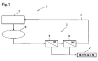
- FIG. 1 is a flowchart of an etching apparatus provided with an etching solution processing apparatus 1 according to an embodiment of the present invention.
- the etching solution in the etching tank 2 is heated to about 80 to 90.degree.
- the etching solution in the etching tank 2 is circulated through the circulation means 6, the membrane separation means 3 and the return pipe 8.
- the etching solution contains 0.05 to 2 mol / L, particularly about 1 to 1.5 mol / L of NaOH, and 0.01 mol / L or more, for example, 0.1 to 0.2 mol / L of an organic additive.
- an organic additive include surfactants such as caprylic acid, lauric acid, 4-propylbenzoic acid, and isopropyl alcohol.
- a crystalline silicon wafer such as a semiconductor wafer is set in a casing and immersed in the etching solution in the etching tank 2, and a plurality of silicon wafers are textured simultaneously. By this texture treatment, silicon and dopant are eluted from the silicon wafer.
- Etching solution in the etching tank 2 is passed through the membrane separation means 3 by a pump provided in the circulation means 6.
- the membrane separation means 3 separates the silicon compound, dopant ions, and the like from the etching solution.
- the ultrafiltration membrane (hereinafter sometimes referred to as a UF membrane) module 4 and the nano are used.
- a filtration membrane (hereinafter sometimes referred to as NF membrane) module 5 is provided.
- the membrane permeate that has passed through the UF membrane module 4 and the NF membrane module 5 is returned to the etching tank 2 via the return pipe 8, and the separation liquid (concentrate) of the etchant that does not pass through the UF membrane and the NF membrane is as follows. Each is sent to the waste water treatment step 7 for treatment.
- the UF membrane of the UF membrane module 4 has a membrane pore size larger than that of the NF membrane.
- a polymer obtained by polymerizing silicon components and other polyion complexes such as dopants are removed by the UF membrane.
- the UF membrane module may be omitted.
- the UF membrane of the UF membrane module 4 preferably has a pore size of 2 to 100 nm and a molecular weight cut off of about 1,000 to 300,000. Further, as a material for the UF membrane, cellulose acetate, polyacrylonitrile, polysulfone, polytetrafluoroethylene, polyethersulfone, polyvinylidene fluoride, and the like are suitable.
- the NF membrane is a membrane having a pore diameter between the UF membrane and the RO membrane and having a charge on the membrane material surface.
- those capable of removing at least divalent or higher polyvalent ions are used, and divalent or higher polyvalent ions may be selectively removed.
- a monovalent alkali metal ion and hydroxide ion may be removed.
- the NF film may remove divalent or higher valent ions, monovalent alkali metal ions, and hydroxide ions.
- the NF membrane preferably has a molecular weight cut-off of 150 to 2000, particularly about 200 to 1000. When it is desired to transmit the target organic substance, an NF film having a higher molecular weight cutoff than that of the organic substance may be used.
- NF membrane permeate becomes alkaline with a pH of about 13 to 14, and contains monovalent silicate ions (for example, HSiO 3 ⁇ ).
- monovalent silicate ions for example, HSiO 3 ⁇
- a part of silicon is a divalent ion (for example, SiO 3 2 ⁇ ) under a highly alkaline condition of pH 13 or higher. Therefore, by setting the etching solution to a pH of 13 or more, SiO 3 2 ⁇ and divalent condensed silicate ions are removed from the etching solution.
- the separation liquid becomes alkaline and silicic acid is ionized.
- the ring can be suppressed. If monovalent alkali metal ions and hydroxide ions are removed by 20 to 50%, preferably 30 to 40%, the alkalinity of the etching solution can be maintained while preventing fouling of the NF film. .
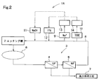
- the return pipe 8 is connected to the alkali concentration measuring means 9 such as Na in the membrane permeate from the membrane separation means 3 and the interface.
- TOC concentration measuring means 10 for measuring the concentration of organic substances such as activator and IPA
- alkali adding means 11 for adding alkali to the membrane permeate according to the alkali concentration in the membrane permeate measured by the measuring means 9
- measurement Organic substance adding means 12 for adding an organic substance to the membrane permeate according to the organic substance concentration in the membrane permeate measured by the means 10 is provided.
- the detection signals of the measuring means 9 and 10 are respectively input to the controllers 13 and 14, and the adding means 11 and 12 are controlled by the controllers 13 and 14.
- alkali concentration measurement means examples include refractive index, viscometer, pH meter, neutralization titration, and ultrasonic wave
- organic additive concentration measurement means include TOC meter, IR (infrared), Raman spectroscopy, and ultraviolet. Examples include light absorption and visible light absorption.
- the alkali and organic additives added to the etching solution by the adding means 11 and 12 are the same as the alkali and organic additives in the etching solution in the etching tank 2.
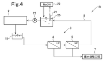
- the solution returning from the NF membrane module 5 to the etching tank 2 is received in the NaOH concentration adjusting tank 20, and the NaOH concentration sensor 21 detects the NaOH concentration.
- This NaOH concentration is given to the NaOH addition device 22, and an NaOH solution (for example, a 25% concentration NaOH solution) is added so that the NaOH concentration in the adjustment tank 20 is equivalent to the NaOH concentration in the etching tank 2.
- the liquid in the adjustment tank 20 is returned to the etching tank 2 by the pump 23.
- the liquid in the etching tank 2 is sent to the UF membrane module 4 through the relay tank 18.
- the other structure is the same as that of FIG. 1, and the same code
- the concentrate is discharged from the membrane separation means to the waste water treatment process 7. Therefore, a fresh etching solution is replenished to the etching apparatus 2 so that the liquid level in the etching tank 2 is kept constant during operation.
- This fresh etching solution is the same as the unused etching solution before starting the etching.
- Examples of the treatment method in the wastewater treatment process 7 include neutralization, coagulation precipitation, crystallization, and dryer drying.
- the concentrate from the membrane modules 4 and 5 has strong alkalinity, it is necessary to perform neutralization.
- a silicon component or the like contained in a high concentration alkaline solution is separated by membrane treatment, and the membrane permeate is returned to the etching tank.
- the load of the wastewater treatment process 7 can be reduced, for example, by reducing the amount of acid necessary for the sum.
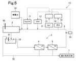
- the etching processing apparatus 1C in FIG. 5 is configured to send the liquid in the etching tank 2 to the UF membrane module 4 through the relay tank 18 in the etching liquid processing apparatus 1A in FIG. Further, the etching processing apparatus 1 ⁇ / b> C further includes an electrical conductivity sensor 33 that measures electrical conductivity as an alkali concentration measuring unit such as Na in the membrane permeate from the membrane separation unit 3 in the return pipe 8. The detection signal of the sensor 33 is input to the controller 13. The controller 13 controls the alkali addition means 11 based on the detection value of the sensor 33 and the measurement value of the alkali concentration measurement means 9.
- electrical conductivity sensors 30 and 31 are also provided in the etching tank 2 and the relay tank 18, respectively.
- a diluting water adding device 34 for adding diluting water to the liquid returned to the etching tank 2 is provided.
- a line 32 for returning a part of the concentrated liquid of the UF membrane module 4 and the NF membrane module 5 to the relay tank 18 is provided.
- the other structure of FIG. 5 is the same as that of FIG. 2, and the same code
- the reason for measuring the electrical conductivity in FIG. 5 is as follows. That is, when silicon dissolves in an alkaline solution and silicate ions increase, OH ⁇ is consumed, and the pH decreases. Since the molar conductivity of OH ⁇ at infinite dilution is 3 to 4 times higher than that of other anions, the electrical conductivity decreases as OH ⁇ is consumed. Therefore, the electrical conductivity can be one of the indices representing the silicic acid component in the alkaline solution.
- the Na ion concentration in the alkaline solution is known in advance, it is possible to calculate the presence or concentration of silicate ions only from the electrical conductivity, but if Na ions can be detected by another means, The accuracy can be increased.
- the location where the electrical conductivity is measured is not particularly specified, but an etching tank, a relay tank, or a permeate is preferable.
- the etching tank As the silicate ion concentration increases, the OH ⁇ concentration decreases and the conductivity decreases. Therefore, it is preferable to maintain the electrical conductivity constant by overflowing the etching solution while supplying the new alkali solution.
- the overflowed etching solution is allowed to flow into the relay tank 18 and then processed by the membrane separation means 3 to obtain an alkali purified solution.
- the arithmetic unit calculates the alkali concentration and the silicic acid concentration from at least one of the detection results, and determines the operating pressure and ON of the membrane modules 4 and 5. / OFF management may be performed.
- a sensor is provided in the return line 8 from the membrane separation means 3 to the etching tank 2, and an IPA solution, an NaOH solution and dilution water are added to the line 8.
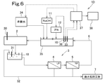
- the etching solution processing apparatus in FIG. In 1D an etching solution adjusting tank 35 is provided in the middle of the line 8, and sensors such as a TOC concentration measuring means 10, an electric conductivity meter 33, and a refractometer 36 are provided in the adjusting tank 35, and an IPA solution is provided in the adjusting tank 35. Add NaOH solution and dilute water.
- Detection signals from the electric conductivity meter 33 and the refractometer 36 are input to a controller 37, and the controller 37 controls the alkali addition means 11 and the dilution water addition device 34.
- an alarm generator 38 When the measured value of the refractometer 36 exceeds the threshold value, an alarm generator 38 generates an NF membrane exchange alarm, and the entire amount of the etching solution from the relay tank 18 is treated as wastewater without passing through the membrane separation means 3.
- the diluting water from the diluting water adding apparatus 34 and the NaOH solution from the alkali adding means 11 are supplied to the etching tank 2 through the adjusting tank 35.
- the etching solution processing apparatus of the present invention includes a liquid temperature adjusting unit for adjusting the liquid temperature (T 1 ) of the etching solution supplied to the membrane separating unit 3, and the liquid temperature of the membrane permeate from the membrane separating unit 3 ( There may be provided at least one liquid temperature adjusting means for adjusting T 2 ), and in particular for adjusting the liquid temperature (T 1 ) of the etching solution supplied to the membrane separation means 3.
- a liquid temperature adjusting means and a liquid temperature adjusting means for adjusting the liquid temperature (T 2 ) of the membrane permeate from the membrane separating means 3 are provided, and heat exchange is performed by the liquid temperature adjusting means before and after the membrane separating means 3. You may do it.
- the liquid temperature (T 1 ) is adjusted by such a liquid temperature adjusting means, the removal rate of divalent silicate ions is improved. The reason for this will be described next.
- the removal rate of divalent silicate ions originates from the temperature dependence of the dissociation equilibrium constant of water, and can be explained by equation (1) derived thermodynamically.
- K is an ion product of water
- T is an absolute temperature
- R is a gas constant
- ⁇ r H ⁇ is a standard reaction enthalpy.
- the subscript p on the left side indicates equilibrium under constant pressure.
- the ionic product K of water decreases with increasing temperature, so that the pH of the solution decreases and dissociation hardly occurs. That is, the amount of divalent silicate ions to be removed is reduced. Accordingly, in order to increase the removal efficiency of divalent silicate ions, treatment at a low temperature is preferable. Note that if the liquid temperature is too low, the amount of permeated water of the NF membrane decreases, so the divalent silicate ion and the amount of permeated water are in a trade-off relationship. Therefore, it is preferable to consider the liquid temperature setting and the number of NF films according to the composition of the etching liquid.
- the temperature (T 1 ) of the etching solution supplied to the membrane separation means 3 is preferably 10 to 70 ° C., particularly about 30 to 50 ° C.
- T 1 the temperature of the etching solution supplied to the membrane separation means 3
- the removal rate of divalent silicate ions may be reduced, and the membrane module may be defective.
- a liquid having a temperature lower than 10 ° C. is passed, although depending on the operation pressure, the membrane may be consolidated and the amount of permeated water of the membrane may be reduced.
- the heat exchanger 42 is a liquid temperature adjusting means for adjusting the liquid temperature (T 1 ) of the etching liquid introduced into the relay tank 43, and the heat exchanger 41 is a liquid of the membrane permeate from the membrane separation means 3. This is a liquid temperature adjusting means for adjusting the temperature (T 2 ).
- T 1 liquid temperature of the etching liquid introduced into the relay tank 43
- T 41 is a liquid of the membrane permeate from the membrane separation means 3.
- T 2 a liquid temperature adjusting means for adjusting the temperature (T 2 ).
- the heat exchanger 42 is for maintaining the water temperature in the relay tank 43, and performs heat exchange between the concentrated liquid (for example, 50 ° C. or less) of the NF membrane module and the high-temperature solution from the etching tank 2.
- the permeation flow rate can be set to the maximum by raising the temperature to the membrane's tolerance temperature.
- the silica removal rate decreases as the temperature of the liquid increases.
- the permeation flux is also relatively large, so that there is little influence in operation at low temperatures.
- NF membrane module 5 only one NF membrane module 5 is installed, but two or more NF membrane modules may be installed in series. In this way, the removal rate of silicic acid from the etching solution can be increased. For example, when only one stage of NF membrane with a silicic acid removal rate of 50% is installed, the silicic acid removal rate is 50%, but when the same NF membrane module is installed in two stages in series, the total 75% of silicic acid can be removed.
- the capacity of the etching tank 2 is 8 m 3 , and NaOH: 54600 mg / L as an unused etchant in this IPA: 11700 mg / L NaOH and IPA aqueous solution with a concentration of.
- the liquid temperature of the etching solution was set to 85 ° C., the silicon wafer was immersed for about 30 minutes, and etching processing was performed one after another.
- the etching tank 2 was appropriately supplemented with a fresh etching solution so that the liquid level in the tank was constant. By continuing the etching, silicon and dopant were eluted from the silicon wafer, and their concentrations in the etching solution gradually increased.
- the etching solution had the composition shown in Table 1. Therefore, the entire etching solution in the system including the etching tank 2 and the return pipe 8 was replaced with a fresh etching solution. Etching was performed again.
- Example 1 The apparatus shown in FIG. 1 was used as an etching solution processing apparatus.
- capacitance of the etching tank 2 is the same as the comparative example 1, and the specification and operating conditions of the UF membrane module 4 and the NF membrane module 5 are as follows.
- UF membrane module 4 “NTU-3306-K6R” manufactured by Nitto Denko Corporation
- NF membrane module 5 “NP030” manufactured by NADIR, Germany
- Water introduced into UF membrane module 4 58 L / min
- Liquid temperature (T 1 ) of the liquid introduced into the UF membrane module 4 liquid passed through the chiller (not shown) after heat exchange with the permeate of the NF membrane module 5): 20 ° C.
- Liquid temperature (T 2 ) of the liquid returned to the etching tank 2 liquid passed through a heater (not shown) after heat exchange with the liquid from the circulation means 6): 80 ° C.
- the etching solution in the etching tank 2 was assumed to be dirty after 12 hours of operation in Comparative Example 1 above.
- Comparative Example 1 the entire amount of the dirty etching solution was discarded as shown in Table 1, but in this example, the operation was continued while the dirty etching solution was subjected to membrane permeation treatment.
- the water recovery rates of the UF membrane module 4 and the NF membrane module 5 were both 90%.
- the etching tank 2 was appropriately supplemented with a fresh etching solution so that the water level in the etching tank 2 was constant.
- Table 2 shows the composition of the permeated liquid of the NF membrane 5 when 12 hours have passed since the operation of Example 1 was started. For reference, Table 2 also shows the waste liquid composition of Table 1 as the raw water composition.
- Example 2 As shown in FIG. 2, an etching solution processing apparatus having an alkali (NaOH in this embodiment) adding means and an organic additive (IPA in this embodiment) adding means was used. Others were etched under the same conditions as in Example 1.
- the alkali concentration measuring means 9 As the alkali concentration measuring means 9, a pH meter was used, and an aqueous NaOH solution (concentration 24%) was added by a chemical injection pump so that the Na + concentration after addition was 31400 mg / L.
- IPA concentration measuring means 10 As the IPA concentration measuring means 10, a TOC meter was used, and an IPA aqueous solution (concentration 20%) was added to the return pipe 8 by a chemical injection pump so that the IPA concentration after addition was 11700 mg / L.
- Table 2 shows the composition of the etchant in the return pipe 8 on the downstream side of the pouring points of NaOH and IPA (when 12 hours have elapsed since the operation started).
- the amount of the concentrated liquid sent from each membrane module 4 and 5 to the waste etching treatment step is 8 m 3 in total per day, and the amount of waste liquid may be significantly smaller than that in Comparative Example 1. Admitted.
- Example 1 it can be seen that the removal rate of impurities SiO 2 and PO 4 3 ⁇ is higher than that of Na + . Further, by combining the UF membrane module and NF membrane module, it can be seen that Crossed flow back to the etching tank Na + by separating the SiO 2. Further, it can be seen that the TOC value indicating the concentration of the organic additive that is important when forming irregularities on the silicon surface hardly changes before and after membrane separation and can be reused.
- the concentration of SiO 2 is high, if the use is continued without performing membrane separation, the etching rate of the silicon wafer becomes slow and it becomes difficult to obtain the desired texture shape, so the concentration of SiO 2 is about 20000 to 25000 mg / Before reaching L, it is discharged and the etching solution needs to be replaced.
- the UF membrane and the NF membrane module are combined as in the first and second embodiments, SiO 2 and PO 4 3 ⁇ can be separated and most of Na + can be returned to the etching tank 2. Therefore, the amount of NaOH used can be reduced by half. Thereby, the usage period of the etching solution can be doubled or more, and the amount of NaOH discharged to the wastewater treatment process can be halved, so that the amount of acid used for neutralization can also be reduced. it can.
- the etching solution had the composition shown in Table 3. Therefore, the entire etching solution in the system was replaced with a fresh etching solution, and etching was performed again.
- Comparative Example 3 In Comparative Example 2 described above, the etching rate decreases as the SiO 2 concentration increases. In Comparative Example 3, a new NaOH solution (concentration 40000 mg / L) was continuously added at 60 L / h so that the SiO 2 concentration was about 10,000 mg / L in order to keep the etching rate constant.
- Example 4 The apparatus shown in FIG. 4 was used as an etching liquid processing apparatus.
- the capacity of the etching tank 2 is the same as in Comparative Example 2, and the specifications and operating conditions of the UF membrane module 4 and the NF membrane module 5 are as follows.
- the concentrated solution from the membrane separation means 3 is not returned to the relay tank 18 but is a processing result when it is processed temporarily.
- UF membrane module 4 “NTU-3306-K6R” manufactured by Nitto Denko Corporation
- NF membrane module 5 Two 8-inch NF membranes with a molecular weight cut-off of 300 in series.
- the liquid introduced into the UF membrane module 4 is a solution that has passed through a chiller (not shown) after heat exchange with the permeate of the NF membrane module 5, and the liquid temperature is 50 ° C.
- the liquid returned to the etching tank 2 is a liquid that has passed through a heater (not shown) after heat exchange with the liquid from the relay tank 18, and the liquid temperature is 80 ° C.
- the liquid temperature of the relay tank 18 is 50 ° C.
- the etching solution in the etching tank 2 was brought into a state after operation for 12 hours in the above Comparative Example 2, and the treatment was started from this state.
- Comparative Example 2 the entire amount of the dirty etching solution was discarded as shown in Table 3, but in Example 4, the operation was continued while the dirty etching solution was subjected to membrane permeation treatment.
- the water recovery rate of the UF membrane module 4 was 90%, and the water recovery rate of the NF membrane module 5 was 50%, which was 45% in total.
- the etching tank 2 was appropriately supplemented with a fresh etching solution so that the water level in the etching tank 2 was constant.
- Table 4 shows the composition of the permeated liquid of the NF membrane 5 when 12 hours have passed since the operation of Example 4 was started.
- Table 4 also shows the waste liquid composition of Comparative Example 2 in Table 3 as the raw water composition.
- the removal rate of SiO 2 was 90%, whereas the recovery rate of NaOH was 60%, and NaOH could be selectively recovered.
- Example 5 The etching solution was processed by the apparatus shown in FIG. In this Example 5, the concentrated liquid of the NF membrane module 5 is returned to the relay tank 18 and circulated, so that the water recovery rate is 72% (the water recovery rate of the UF membrane module is 90%, the water recovery rate of the NF membrane module) Increased to 80%). Since the concentrated water of the NF membrane module 5 is circulated through the relay tank, a permeate having a higher NaOH concentration can be obtained. The brine of the UF membrane module 4 was sent to the wastewater treatment process 7. Table 4 shows the liquid composition of the etching tank in Example 5.
- an etching solution processing tank equipped with an etching solution adjusting tank equipped with NaOH addition means and IPA addition means as an organic additive was used.
- the alkali concentration measuring means based on the detection value of the refractometer 36 and the electric conductivity meter (electromagnetic concentration meter (manufactured by Toa DKK)) 33, the NaOH concentration in the tank 35 is 40,000 mg / L.
- An aqueous NaOH solution (concentration: 25% by weight) was added by addition means 11 comprising a chemical injection pump.
- a certain amount of dilution water is injected from the dilution water adding device 34 into the etching solution adjusting tank 35 so that the SiO 2 concentration in the etching tank 2 is about 10,000 mg / L, and the liquid in the etching tank 2 is reduced.
- the part was overflowed (not shown, flowing directly from the etching tank 2 to the wastewater treatment step).
- the amount of NaOH aqueous solution (concentration 25%) added by the chemical injection pump was increased by an amount that would be 40,000 mg / L when mixed with the dilution water to be added. Since the permeated solution of the NF membrane module 5 had a SiO 2 concentration of 90% or more removed, it was adjusted in the etching solution adjusting tank 35 by adding a short amount of NaOH and IPA.
- the SiO 2 concentration in the etching solution adjusting tank 35 is kept at a low concentration by the removal of SiO 2 by the NF film, but when the measured value of the refractometer 36 exceeds the threshold value, the signal from the controller 17 Based on the above, the alarm generator 38 is operated to issue an NF membrane replacement sign and to a line (not shown) that sends the etching solution from the relay tank 18 to the wastewater treatment process without being treated by the UF membrane module 4. At the same time, the operation was switched to the operation of quantitatively injecting dilution water and 25% NaOH by a signal from the controller 17. By doing so, the etching process can be continuously performed even when the SiO 2 leak occurs due to the deterioration of the NF film.
- an IPA aqueous solution (concentration 20%) was added to the etching solution adjusting tank 35 by the adding means 12 comprising a chemical injection pump so that the IPA concentration was 12000 mg / L.
- Table 5 shows the composition of the etchant sampled in the return line 8 upstream of the etchant adjustment tank 35 (12 hours after the start of operation).
Landscapes
- Engineering & Computer Science (AREA)
- Water Supply & Treatment (AREA)
- Chemical & Material Sciences (AREA)
- Chemical Kinetics & Catalysis (AREA)
- Nanotechnology (AREA)
- Organic Chemistry (AREA)
- Life Sciences & Earth Sciences (AREA)
- Environmental & Geological Engineering (AREA)
- Hydrology & Water Resources (AREA)
- General Chemical & Material Sciences (AREA)
- Inorganic Chemistry (AREA)
- Separation Using Semi-Permeable Membranes (AREA)
- Weting (AREA)
Abstract
Description
a)警報(NF膜の交換サイン)を出す、及び/又は、
b)膜処理を行わずに全量を排液とし、同量を新液として補充する運転(後述の比較例2の運転)に切り替えて運転するのが好ましい。

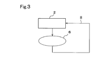
第3図のようにエッチング槽2内のエッチング液を循環手段6及び配管8によって単に循環させるようにしたエッチング装置を用い、シリコンウェハのエッチング処理を行った。
NaOH:54600mg/L
IPA :11700mg/L
の濃度のNaOH及びIPA水溶液を入れた。エッチング液の液温を85℃とし、シリコンウェハを約30分浸漬させ、次々とエッチング処理を行った。なお、エッチング槽2には、槽内の液位が一定となるように新鮮なエッチング液を適宜補充した。エッチングを継続することにより、シリコンウェハからケイ素及びドーパントが溶出し、エッチング液中のそれらの濃度が徐々に上昇した。

エッチング液の処理装置として第1図の装置を用いた。なお、エッチング槽2の容量は比較例1と同一であり、UF膜モジュール4、NF膜モジュール5の仕様及び運転条件は以下の通りである。
NF膜モジュール5:独NADIR社製「NP030」
UF膜モジュール4への導入水量:58L/min
UF膜モジュール4への導入液(NF膜モジュール5の透過液と熱交換後にチラー(図示せず)を通した液)の液温(T1):20℃
エッチング槽2への返送液(循環手段6からの液と熱交換後に加熱器(図示せず)を通した液)の液温(T2):80℃
エッチング液処理装置として第2図に示すようにアルカリ(この実施例ではNaOH)添加手段及び有機添加剤(この実施例ではIPA)添加手段を備えたものを用いた。他は、実施例1と同一条件でエッチングを行った。

表1の通り、実施例1,2では、膜透過液中のSiO2及びPO4 3-濃度が原水と比べて低下しているので、エッチング液の全量交換を行うことなく、エッチング処理を継続することができた。
第8図のエッチング装置を用い、シリコンウェハのエッチング処理を行った。エッチング槽2の容量は200Lであり、この中に未使用のエッチング液として
NaOH:40000mg/L
IPA :12500mg/L
の濃度のNaOH及びIPA水溶液を入れた。エッチング液の液温を85℃とし、シリコンウェハを約30分浸漬させ、次々とエッチング処理を行った。なお、エッチング槽2には、エッチング槽2のSiO2が20000mg/L程度になるように30L/hの添加量にて新鮮なエッチング液を添加手段50から添加し続けた。エッチングを継続することにより、ケイ素及びドーパントが溶出し、エッチング液中のそれらの濃度が徐々に上昇した。

上記の比較例2ではSiO2濃度の増加に伴ってエッチング速度が低下している。比較例3では、エッチング速度を一定に保つためにSiO2濃度が10000mg/L程度となるように常に新液のNaOH溶液(濃度40000mg/L)を60L/hにて添加し続けた。
エッチング液の処理装置として第4図の装置を用いた。エッチング槽2の容量は比較例2と同一であり、UF膜モジュール4、NF膜モジュール5の仕様及び運転条件は以下の通りである。この実施例4は膜分離手段3からの濃縮液を中継槽18に返送せずに、一過式処理した時の処理結果となる。
NF膜モジュール5:分画分子量300の8インチNF膜2本直列
UF膜モジュール4への導入水量:10L/min
なお、UF膜モジュール4への導入液は、NF膜モジュール5の透過液と熱交換後にチラー(図示せず)を通した液であり、その液温は50℃である。

第6図の装置によってエッチング液の処理を行った。この実施例5では、NF膜モジュール5の濃縮液を中継槽18に戻して循環することにより、水回収率を72%(UF膜モジュールの水回収率は90%、NF膜モジュールの水回収率は80%)まで高めた。NF膜モジュール5の濃縮水を中継槽に循環させているため、より高いNaOH濃度の透過液を得ることができる。UF膜モジュール4のブラインは廃水処理工程7へ送った。表4に、この実施例5におけるエッチング槽の液組成を示した。

なお、本出願は、2009年3月31日付で出願された日本特許出願(特願2009-086345)に基づいており、その全体が引用により援用される。
Claims (12)
- シリコンをエッチング処理したエッチング液を循環再利用するためのエッチング液の処理装置であって、
エッチング槽からのエッチング液を膜分離処理する膜分離手段と、
該膜分離手段の膜透過液を該エッチング槽に循環させる循環手段と、
を備えたことを特徴とするエッチング液の処理装置。 - 請求項1において、前記膜分離手段は、2価以上の多価イオンを選択的に除去するナノ濾過膜を備えたものであることを特徴とするエッチング液の処理装置。
- 請求項1において、前記膜分離手段は、2価以上の多価イオン、1価のアルカリ金属イオン及び水酸化物イオンを除去するナノ濾過膜を備えたものであることを特徴とするエッチング液の処理装置。
- 請求項2又は3において、前記ナノ濾過膜はアルカリ液に耐性があり、70℃まで温度耐性があり、分画分子量が150~2000であることを特徴とするエッチング液の処理装置。
- 請求項2ないし4のいずれか1項において、前記膜分離手段は、ナノ濾過膜の前段に限外濾過膜を備えたものであることを特徴とするエッチング液の処理装置。
- 請求項1ないし5のいずれか1項において、前記膜分離手段の膜透過液中のアルカリ濃度及び有機物濃度を計測する濃度計測手段と、
該計測手段により計測した膜透過液中のアルカリ濃度に応じて、膜透過液にアルカリを添加するアルカリ添加手段と、
該計測手段により計測した膜透過液中の有機物濃度に応じて、膜透過液に有機物を添加する有機物添加手段と、
を備えたことを特徴とするエッチング液の処理装置。 - 請求項6において、アルカリ濃度及び/又は有機物濃度に応じて膜透過液に希釈水を添加する希釈水添加手段を備えたことを特徴とするエッチング液の処理装置。
- 請求項6又は7において、エッチング槽からのエッチング液又は膜分離手段の膜透過液の電気伝導率又は電気伝導率とNaイオン濃度を測定し、この結果に基いてアルカリ添加手段又は有機物添加手段が制御されることを特徴とするエッチング液の処理装置。
- 請求項6ないし8のいずれか1項において、膜分離手段の透過前後の電気伝導率又は膜透過液のアルカリ濃度に基づいて膜交換信号を出力する信号出力手段を備えたことを特徴とするエッチング液の処理装置。
- 請求項1ないし9のいずれか1項において、前記エッチング液の処理装置は、前記膜分離手段に供給されるエッチング液の液温(T1)を調節するための液温調節手段、及び前記膜分離手段からの膜透過液の液温(T2)を調節するための液温調節手段の少なくとも一方の液温調節手段を備えたことを特徴とするエッチング液の処理装置。
- 請求項10において、膜分離手段からエッチング槽に戻る液と、エッチング槽から膜分離手段に向って流出する液との熱交換を行う熱交換器を備えたことを特徴とするエッチング液の処理装置。
- 請求項1ないし11のいずれか1項に記載のエッチング液の処理装置を用いることを特徴とするエッチング液の処理方法。
Priority Applications (6)
| Application Number | Priority Date | Filing Date | Title |
|---|---|---|---|
| DE201011001432 DE112010001432T5 (de) | 2009-03-31 | 2010-03-26 | Vorrichtung und Verfahren zur Aufbereitung einer Ätzlösung |
| KR1020117019458A KR101704376B1 (ko) | 2009-03-31 | 2010-03-26 | 에칭액의 처리 장치 및 처리 방법 |
| CN201080012806.2A CN102356454B (zh) | 2009-03-31 | 2010-03-26 | 蚀刻液的处理装置以及处理方法 |
| US13/138,659 US20120006790A1 (en) | 2009-03-31 | 2010-03-26 | Apparatus and method for treating etching solution |
| JP2011507151A JP5477375B2 (ja) | 2009-03-31 | 2010-03-26 | エッチング液の処理装置及び処理方法 |
| US14/961,028 US10249505B2 (en) | 2009-03-31 | 2015-12-07 | Method for treating etching solution |
Applications Claiming Priority (2)
| Application Number | Priority Date | Filing Date | Title |
|---|---|---|---|
| JP2009-086345 | 2009-03-31 | ||
| JP2009086345 | 2009-03-31 |
Related Child Applications (2)
| Application Number | Title | Priority Date | Filing Date |
|---|---|---|---|
| US13/138,659 A-371-Of-International US20120006790A1 (en) | 2009-03-31 | 2010-03-26 | Apparatus and method for treating etching solution |
| US14/961,028 Continuation US10249505B2 (en) | 2009-03-31 | 2015-12-07 | Method for treating etching solution |
Publications (1)
| Publication Number | Publication Date |
|---|---|
| WO2010113792A1 true WO2010113792A1 (ja) | 2010-10-07 |
Family
ID=42828083
Family Applications (1)
| Application Number | Title | Priority Date | Filing Date |
|---|---|---|---|
| PCT/JP2010/055357 Ceased WO2010113792A1 (ja) | 2009-03-31 | 2010-03-26 | エッチング液の処理装置及び処理方法 |
Country Status (8)
| Country | Link |
|---|---|
| US (2) | US20120006790A1 (ja) |
| JP (1) | JP5477375B2 (ja) |
| KR (1) | KR101704376B1 (ja) |
| CN (1) | CN102356454B (ja) |
| DE (1) | DE112010001432T5 (ja) |
| MY (1) | MY166203A (ja) |
| TW (1) | TWI480232B (ja) |
| WO (1) | WO2010113792A1 (ja) |
Cited By (8)
| Publication number | Priority date | Publication date | Assignee | Title |
|---|---|---|---|---|
| JP2012134237A (ja) * | 2010-12-20 | 2012-07-12 | Kurita Water Ind Ltd | アルカリエッチング液の処理装置及び処理方法 |
| JP2013197360A (ja) * | 2012-03-21 | 2013-09-30 | Shibaura Mechatronics Corp | 基板処理方法及び基板処理システム |
| WO2014038277A1 (ja) * | 2012-09-06 | 2014-03-13 | 三菱電機株式会社 | 太陽電池の製造装置およびこれを用いた太陽電池の製造方法 |
| EP2717321A4 (en) * | 2011-06-03 | 2015-05-06 | Sanyo Electric Co | PROCESS FOR THE PRODUCTION OF SOLAR CELLS |
| JP2015093235A (ja) * | 2013-11-12 | 2015-05-18 | 株式会社旭製作所 | Si含有リン酸系廃液からSiを除去又は低減する方法 |
| JP2018018990A (ja) * | 2016-07-28 | 2018-02-01 | 株式会社カネカ | エッチング処理装置、およびエッチング処理方法 |
| CN108103585A (zh) * | 2017-12-25 | 2018-06-01 | 湖州富优得膜分离科技有限公司 | 一种单晶硅片制绒废液的处理方法 |
| WO2025187237A1 (ja) * | 2024-03-06 | 2025-09-12 | 日東電工株式会社 | 浄化水の製造方法、及びシリカスケールリスクの低減方法 |
Families Citing this family (18)
| Publication number | Priority date | Publication date | Assignee | Title |
|---|---|---|---|---|
| JP2013229387A (ja) * | 2012-04-24 | 2013-11-07 | Mitsubishi Electric Corp | エッチング装置およびこれを用いた太陽電池の製造方法 |
| CN102677062B (zh) * | 2012-05-21 | 2014-01-22 | 嘉兴学院 | 一种电解再生碱性蚀刻液的方法 |
| WO2014151778A1 (en) | 2013-03-15 | 2014-09-25 | Tel Fsi, Inc | Processing system and method for providing a heated etching solution |
| KR101410032B1 (ko) * | 2014-01-20 | 2014-06-20 | 강훈 | 에칭액 측정 및 제어시스템 |
| US10170350B2 (en) * | 2014-05-02 | 2019-01-01 | Naura Akrion Inc. | Correlation between conductivity and pH measurements for KOH texturing solutions and additives |
| JP6383254B2 (ja) * | 2014-11-04 | 2018-08-29 | 株式会社東芝 | 処理装置および処理方法 |
| EP3133175A1 (en) * | 2015-08-19 | 2017-02-22 | Enthone, Inc. | System and process for recovering catalytic precious metal from aqueous galvanic processing solution |
| CN105483706B (zh) * | 2015-11-30 | 2019-04-23 | 广东骏亚电子科技股份有限公司 | 一种印刷电路板酸、碱性氯化铜蚀刻废液循环利用装置及其方法 |
| US12227433B2 (en) | 2016-02-19 | 2025-02-18 | Hewlett Packard Enterprise Development Lp | Electrical frequency response fluid analysis |
| CN105742213B (zh) * | 2016-03-07 | 2019-03-12 | 京东方科技集团股份有限公司 | 湿法刻蚀设备及湿法刻蚀方法 |
| DE102016004612A1 (de) * | 2016-04-19 | 2017-10-19 | Merck Patent Gmbh | Verfahren und Befüllungsvorrichtung zum Befüllen eines Transportbehälters mit einem Fluid |
| CN107195728A (zh) * | 2017-06-23 | 2017-09-22 | 江阴鑫辉太阳能有限公司 | 一种太阳能电池返工片的处理方法 |
| WO2019143903A1 (en) | 2018-01-18 | 2019-07-25 | Chia Ming Chen | Color mixing from different light sources |
| US11555798B2 (en) * | 2018-10-08 | 2023-01-17 | Eci Technology, Inc. | Selective monitoring of multiple silicon compounds |
| JP7438171B2 (ja) * | 2021-09-13 | 2024-02-26 | 芝浦メカトロニクス株式会社 | 供給タンク、供給装置、供給システム |
| JP7438172B2 (ja) * | 2021-09-13 | 2024-02-26 | 芝浦メカトロニクス株式会社 | 供給装置、供給システム |
| JP7504940B2 (ja) * | 2022-03-09 | 2024-06-24 | 芝浦メカトロニクス株式会社 | 基板処理装置 |
| EP4544486A1 (en) * | 2022-09-09 | 2025-04-30 | Evoqua Water Technologies LLC | Enabling internet of things (iot) capabilities in legacy water treatment systems |
Citations (4)
| Publication number | Priority date | Publication date | Assignee | Title |
|---|---|---|---|---|
| JPH0418435U (ja) * | 1990-06-01 | 1992-02-17 | ||
| JPH09219388A (ja) * | 1996-02-08 | 1997-08-19 | Mitsubishi Electric Corp | 半導体製造装置 |
| JPH10326769A (ja) * | 1997-05-26 | 1998-12-08 | Mitsubishi Materials Shilicon Corp | 半導体ウェーハ処理溶液の管理方法およびその制御装置 |
| JP2002361249A (ja) * | 2001-06-01 | 2002-12-17 | Nagase & Co Ltd | 現像廃液再生装置及び現像廃液再生方法 |
Family Cites Families (42)
| Publication number | Priority date | Publication date | Assignee | Title |
|---|---|---|---|---|
| DE3782205T2 (de) * | 1986-07-23 | 1993-02-25 | Sumitomo Heavy Industries | Behandlung einer photoresistmaterialien enthaltenden abfalloesung. |
| JPS6442824A (en) * | 1987-08-11 | 1989-02-15 | Kyushu Electron Metal | Wet etching |
| JPH0419388A (ja) * | 1990-05-14 | 1992-01-23 | Shigemitsu Fujii | スクリューポンプ |
| US5158683A (en) * | 1991-09-03 | 1992-10-27 | Ethyl Corporation | Bromide separation and concentration using semipermeable membranes |
| US5205937A (en) * | 1992-04-30 | 1993-04-27 | U.S. Filter Membralox | Recovery and reuse of water-based cleaners |
| US5476591A (en) * | 1993-05-25 | 1995-12-19 | Harrison Western Environmental Services, Inc. | Liquid treatment system and method for operating the same |
| US5503750A (en) * | 1993-10-04 | 1996-04-02 | Russo, Jr.; Lawrence J. | Membrane-based process for the recovery of lactic acid by fermentation of carbohydrate substrates containing sugars |
| DE4406952A1 (de) * | 1994-03-03 | 1995-09-07 | Bayer Ag | Verfahren zur Aufkonzentration von Lackoverspray |
| FR2721227B1 (fr) * | 1994-06-17 | 1996-08-14 | Kodak Pathe | Procédé et dispositif pour la séparation de substance dissoutes dans les eaux de rinçage utilisées en aval d'un bain de traitement d'un film photographique. |
| US5811224A (en) * | 1994-08-24 | 1998-09-22 | Bayer Corporation | Process for rejuvenating developer in printing plate development |
| DE19600967C2 (de) * | 1996-01-12 | 1998-06-04 | Schweizer Electronic Ag | Verfahren zum Auftrennen von aus der Leiterplattenherstellung stammenden organischen Prozeßlösungen |
| US8758720B2 (en) * | 1996-08-12 | 2014-06-24 | Debasish Mukhopadhyay | High purity water produced by reverse osmosis |
| US6537456B2 (en) * | 1996-08-12 | 2003-03-25 | Debasish Mukhopadhyay | Method and apparatus for high efficiency reverse osmosis operation |
| DE19710563C2 (de) * | 1997-03-14 | 2003-10-02 | Daimler Chrysler Ag | Verfahren und Vorrichtung zum Betreiben von Aluminium-Fräsbädern |
| MY119304A (en) * | 1997-12-11 | 2005-04-30 | Shinetsu Handotai Kk | Silicon wafer etching method and silicon wafer etchant |
| JP3695932B2 (ja) * | 1998-02-12 | 2005-09-14 | 三洋電機株式会社 | 凹凸基板の製造方法 |
| US6132618A (en) * | 1998-04-16 | 2000-10-17 | Pq Corporation | System and method for waking a computer having a plurality of power resources from a system state using a data structure |
| JP3434750B2 (ja) * | 1999-09-30 | 2003-08-11 | Necエレクトロニクス株式会社 | 洗浄装置のライン構成及びその設計方法 |
| US6365051B1 (en) * | 1999-10-12 | 2002-04-02 | Mansour S. Bader | Precipitation-membrane distillation hybrid system for the treatment of aqueous streams |
| US6503363B2 (en) * | 2000-03-03 | 2003-01-07 | Seh America, Inc. | System for reducing wafer contamination using freshly, conditioned alkaline etching solution |
| JP3948890B2 (ja) | 2000-08-09 | 2007-07-25 | 三洋電機株式会社 | 凹凸基板の製造方法、凹凸構造形成用界面活性剤並びに光起電力素子の製造方法 |
| JP2003229392A (ja) * | 2001-11-28 | 2003-08-15 | Shin Etsu Handotai Co Ltd | シリコンウエーハの製造方法及びシリコンウエーハ並びにsoiウエーハ |
| EP1329425A1 (en) * | 2002-01-18 | 2003-07-23 | Toray Industries, Inc. | Desalination method and desalination apparatus |
| AU2003216896A1 (en) * | 2002-04-08 | 2003-10-20 | Akzo Nobel N.V. | Method for removing a nitrogen oxide from a gas |
| CN1298636C (zh) * | 2002-11-29 | 2007-02-07 | 长濑产业株式会社 | 废显影液再生装置和废显影液再生方法 |
| GB0312394D0 (en) * | 2003-05-30 | 2003-07-02 | Weir Westgarth Ltd | Filtration apparatus and method |
| JP4554917B2 (ja) * | 2003-12-09 | 2010-09-29 | 旭化成ケミカルズ株式会社 | シリコンウエハーエッチング用苛性アルカリ水溶液の回収再生方法およびそれによって回収された苛性アルカリ水溶液 |
| JP4424039B2 (ja) * | 2004-04-02 | 2010-03-03 | 株式会社Sumco | 半導体ウェーハの製造方法 |
| US7144513B2 (en) * | 2004-05-06 | 2006-12-05 | Nestec S.A. | Water treatment method in high cycle dispensing systems for scale control |
| TWI306837B (en) * | 2004-08-06 | 2009-03-01 | Asahi Kasei Chemicals Corp | Method for purifying aqueous alkaline solution |
| JP2006278409A (ja) | 2005-03-28 | 2006-10-12 | Sanyo Electric Co Ltd | エッチング装置、テクスチャ基板の製造方法および光起電力装置の製造方法 |
| US7575687B2 (en) * | 2005-08-16 | 2009-08-18 | Ge Osmonics, Inc. | Membranes and methods useful for caustic applications |
| JP4326545B2 (ja) | 2006-02-23 | 2009-09-09 | 三洋電機株式会社 | 凹凸基板の製造方法及び光起電力素子の製造方法 |
| JP2008012916A (ja) * | 2006-06-08 | 2008-01-24 | Hitachi Via Mechanics Ltd | 複合シート、複合シートの加工方法、及びレーザ加工装置 |
| KR101433104B1 (ko) * | 2006-09-28 | 2014-08-22 | 쿠리타 고교 가부시키가이샤 | 인산 함유수로부터 인산을 회수하는 방법 및 장치 |
| JP4944558B2 (ja) * | 2006-10-12 | 2012-06-06 | アプリシアテクノロジー株式会社 | エッチング液の再生方法、エッチング方法およびエッチング装置 |
| US20080128354A1 (en) * | 2006-11-30 | 2008-06-05 | Hw Advanced Technologies, Inc. | Method for washing filtration membranes |
| US8420857B2 (en) * | 2007-08-27 | 2013-04-16 | Mallinckrodt Llc | Removal of silica from water soluble compounds by nanofiltration and reverse phase chromatography |
| JP2009086345A (ja) | 2007-09-28 | 2009-04-23 | Fujifilm Corp | 平版印刷版原版 |
| NO20081386L (no) * | 2008-03-14 | 2009-09-15 | Rec Solar As | Method for texturing silicon surfaces and wafers thereof |
| EP2432740B1 (en) * | 2009-05-18 | 2017-02-22 | Dow Global Technologies LLC | Controlling bacteria with brominated amide biocidal compounds in a water system at pH higher than 6 as well as new brominated compound |
| AU2010361595A1 (en) * | 2010-09-30 | 2013-04-04 | General Electric Company | Membrane filtration process with high water recovery |
-
2010
- 2010-03-26 US US13/138,659 patent/US20120006790A1/en not_active Abandoned
- 2010-03-26 KR KR1020117019458A patent/KR101704376B1/ko not_active Expired - Fee Related
- 2010-03-26 WO PCT/JP2010/055357 patent/WO2010113792A1/ja not_active Ceased
- 2010-03-26 MY MYPI2011004595A patent/MY166203A/en unknown
- 2010-03-26 DE DE201011001432 patent/DE112010001432T5/de not_active Withdrawn
- 2010-03-26 CN CN201080012806.2A patent/CN102356454B/zh not_active Expired - Fee Related
- 2010-03-26 JP JP2011507151A patent/JP5477375B2/ja active Active
- 2010-03-30 TW TW099109625A patent/TWI480232B/zh active
-
2015
- 2015-12-07 US US14/961,028 patent/US10249505B2/en not_active Expired - Fee Related
Patent Citations (4)
| Publication number | Priority date | Publication date | Assignee | Title |
|---|---|---|---|---|
| JPH0418435U (ja) * | 1990-06-01 | 1992-02-17 | ||
| JPH09219388A (ja) * | 1996-02-08 | 1997-08-19 | Mitsubishi Electric Corp | 半導体製造装置 |
| JPH10326769A (ja) * | 1997-05-26 | 1998-12-08 | Mitsubishi Materials Shilicon Corp | 半導体ウェーハ処理溶液の管理方法およびその制御装置 |
| JP2002361249A (ja) * | 2001-06-01 | 2002-12-17 | Nagase & Co Ltd | 現像廃液再生装置及び現像廃液再生方法 |
Cited By (9)
| Publication number | Priority date | Publication date | Assignee | Title |
|---|---|---|---|---|
| JP2012134237A (ja) * | 2010-12-20 | 2012-07-12 | Kurita Water Ind Ltd | アルカリエッチング液の処理装置及び処理方法 |
| EP2717321A4 (en) * | 2011-06-03 | 2015-05-06 | Sanyo Electric Co | PROCESS FOR THE PRODUCTION OF SOLAR CELLS |
| JP2013197360A (ja) * | 2012-03-21 | 2013-09-30 | Shibaura Mechatronics Corp | 基板処理方法及び基板処理システム |
| WO2014038277A1 (ja) * | 2012-09-06 | 2014-03-13 | 三菱電機株式会社 | 太陽電池の製造装置およびこれを用いた太陽電池の製造方法 |
| JP5908096B2 (ja) * | 2012-09-06 | 2016-04-26 | 三菱電機株式会社 | 太陽電池の製造装置およびこれを用いた太陽電池の製造方法 |
| JP2015093235A (ja) * | 2013-11-12 | 2015-05-18 | 株式会社旭製作所 | Si含有リン酸系廃液からSiを除去又は低減する方法 |
| JP2018018990A (ja) * | 2016-07-28 | 2018-02-01 | 株式会社カネカ | エッチング処理装置、およびエッチング処理方法 |
| CN108103585A (zh) * | 2017-12-25 | 2018-06-01 | 湖州富优得膜分离科技有限公司 | 一种单晶硅片制绒废液的处理方法 |
| WO2025187237A1 (ja) * | 2024-03-06 | 2025-09-12 | 日東電工株式会社 | 浄化水の製造方法、及びシリカスケールリスクの低減方法 |
Also Published As
| Publication number | Publication date |
|---|---|
| TW201102352A (en) | 2011-01-16 |
| JP5477375B2 (ja) | 2014-04-23 |
| DE112010001432T5 (de) | 2012-10-25 |
| US10249505B2 (en) | 2019-04-02 |
| CN102356454B (zh) | 2014-03-26 |
| JPWO2010113792A1 (ja) | 2012-10-11 |
| TWI480232B (zh) | 2015-04-11 |
| US20120006790A1 (en) | 2012-01-12 |
| US20160086812A1 (en) | 2016-03-24 |
| KR101704376B1 (ko) | 2017-02-08 |
| MY166203A (en) | 2018-06-14 |
| CN102356454A (zh) | 2012-02-15 |
| KR20120002522A (ko) | 2012-01-05 |
Similar Documents
| Publication | Publication Date | Title |
|---|---|---|
| JP5477375B2 (ja) | エッチング液の処理装置及び処理方法 | |
| TWI855997B (zh) | 含有硬度成分之水的處理裝置及處理方法 | |
| JP5330901B2 (ja) | 塩及び淡水の併産装置及び方法 | |
| CN1176032C (zh) | 一种电子级水的集成膜过程生产方法 | |
| TWI537211B (zh) | 純化強酸或強酸性介質以移除二及更高價之金屬離子的方法 | |
| JP4798644B2 (ja) | 逆浸透膜を用いる脱塩方法 | |
| CN102007579B (zh) | 电子材料用清洗水、电子材料的清洗方法及溶气水的供给系统 | |
| US9718710B2 (en) | Treatment apparatus and method for reusing treatment liquid | |
| CN113797773B (zh) | 一种氧化二硫化钼-氧化石墨烯-pei复合陶瓷纳滤膜及其制备方法 | |
| JP5287908B2 (ja) | 水処理装置 | |
| TW202210420A (zh) | 除鹽裝置的運轉方法 | |
| JP2020121278A (ja) | 水処理方法および水処理装置 | |
| JP5594123B2 (ja) | アルカリエッチング液の処理装置及び処理方法 | |
| JP5880079B2 (ja) | 膜分離方法及び装置 | |
| JP2012210595A (ja) | 酸廃液の処理方法及び処理装置 | |
| TW201615557A (zh) | 含有氨之排放水的處理方法及處理裝置 | |
| CN105142763B (zh) | 用于纯化氢氟酸和硝酸的混合物的反渗透 | |
| CN115697918A (zh) | 水处理方法及水处理装置 | |
| CN118201881A (zh) | 多级反渗透膜处理系统 | |
| JP2019042646A (ja) | シリカ含有水の処理装置および処理方法 | |
| TWI405050B (zh) | 自含氫氧化四烷銨之廢液回收及純化氫氧化四烷銨之方法 | |
| JP7782749B1 (ja) | 調整水の製造装置および調整水の製造方法 | |
| JP7115522B2 (ja) | 脱塩装置の運転方法 | |
| RU2320538C1 (ru) | Способ получения водных силикатов или жидких стекол с использованием жидкой фазы гидротермального раствора | |
| CN118812100A (zh) | 一种用于光伏行业生产的氟回收方法 |
Legal Events
| Date | Code | Title | Description |
|---|---|---|---|
| WWE | Wipo information: entry into national phase |
Ref document number: 201080012806.2 Country of ref document: CN |
|
| 121 | Ep: the epo has been informed by wipo that ep was designated in this application |
Ref document number: 10758564 Country of ref document: EP Kind code of ref document: A1 |
|
| WWE | Wipo information: entry into national phase |
Ref document number: 2011507151 Country of ref document: JP |
|
| ENP | Entry into the national phase |
Ref document number: 20117019458 Country of ref document: KR Kind code of ref document: A |
|
| WWE | Wipo information: entry into national phase |
Ref document number: 13138659 Country of ref document: US |
|
| WWE | Wipo information: entry into national phase |
Ref document number: 1120100014329 Country of ref document: DE Ref document number: 112010001432 Country of ref document: DE |
|
| 122 | Ep: pct application non-entry in european phase |
Ref document number: 10758564 Country of ref document: EP Kind code of ref document: A1 |