WO2010067667A1 - 衝突判定システム、乗員拘束システム、車両 - Google Patents
衝突判定システム、乗員拘束システム、車両 Download PDFInfo
- Publication number
- WO2010067667A1 WO2010067667A1 PCT/JP2009/068334 JP2009068334W WO2010067667A1 WO 2010067667 A1 WO2010067667 A1 WO 2010067667A1 JP 2009068334 W JP2009068334 W JP 2009068334W WO 2010067667 A1 WO2010067667 A1 WO 2010067667A1
- Authority
- WO
- WIPO (PCT)
- Prior art keywords
- collision
- vehicle
- side collision
- determination
- door
- Prior art date
Links
Images


Classifications
-
- B—PERFORMING OPERATIONS; TRANSPORTING
- B60—VEHICLES IN GENERAL
- B60R—VEHICLES, VEHICLE FITTINGS, OR VEHICLE PARTS, NOT OTHERWISE PROVIDED FOR
- B60R21/00—Arrangements or fittings on vehicles for protecting or preventing injuries to occupants or pedestrians in case of accidents or other traffic risks
- B60R21/01—Electrical circuits for triggering passive safety arrangements, e.g. airbags, safety belt tighteners, in case of vehicle accidents or impending vehicle accidents
- B60R21/013—Electrical circuits for triggering passive safety arrangements, e.g. airbags, safety belt tighteners, in case of vehicle accidents or impending vehicle accidents including means for detecting collisions, impending collisions or roll-over
- B60R21/0134—Electrical circuits for triggering passive safety arrangements, e.g. airbags, safety belt tighteners, in case of vehicle accidents or impending vehicle accidents including means for detecting collisions, impending collisions or roll-over responsive to imminent contact with an obstacle, e.g. using radar systems
-
- B—PERFORMING OPERATIONS; TRANSPORTING
- B60—VEHICLES IN GENERAL
- B60R—VEHICLES, VEHICLE FITTINGS, OR VEHICLE PARTS, NOT OTHERWISE PROVIDED FOR
- B60R21/00—Arrangements or fittings on vehicles for protecting or preventing injuries to occupants or pedestrians in case of accidents or other traffic risks
- B60R2021/0002—Type of accident
- B60R2021/0025—Pole collision
-
- B—PERFORMING OPERATIONS; TRANSPORTING
- B60—VEHICLES IN GENERAL
- B60R—VEHICLES, VEHICLE FITTINGS, OR VEHICLE PARTS, NOT OTHERWISE PROVIDED FOR
- B60R21/00—Arrangements or fittings on vehicles for protecting or preventing injuries to occupants or pedestrians in case of accidents or other traffic risks
- B60R21/01—Electrical circuits for triggering passive safety arrangements, e.g. airbags, safety belt tighteners, in case of vehicle accidents or impending vehicle accidents
- B60R2021/01204—Actuation parameters of safety arrangents
- B60R2021/01252—Devices other than bags
- B60R2021/01265—Seat belts
Definitions
- the present invention relates to a technique for determining a collision mode of a vehicle.
- Patent Document 1 discloses a system that detects a side collision using a G sensor or a contact sensor that is activated when a vehicle has a side collision.
- an occupant restraint system such as an air bag module in the event of a vehicle accident
- advanced detection that can quickly detect the occurrence of a vehicle collision in order to improve the occupant restraint performance.
- an object of the present invention is to provide a technique effective for appropriately restraining a vehicle occupant in the case of a side collision of the vehicle.
- the present invention is applied to solve the above problems.
- the present invention is typically applicable to a technique for determining information related to a side collision that has occurred in an automobile, but similarly to a technique for detecting information relating to a side collision that has occurred in a vehicle other than an automobile.
- the present invention can be applied.
- the “vehicle” includes various vehicles such as an automobile, a train, a bus, and a truck.
- the collision determination system is a system mounted on a vehicle, and includes a camera, a side collision sensor, an operation amount detection unit, a determination processing unit, a threshold setting unit, and a control unit.
- the determination processing unit, the threshold setting unit, and the control unit may be individual processing elements or a single processing element.
- the camera is an image detection camera arranged toward the side of the vehicle.
- a monocular camera such as a CMOS or CCD, or a stereo camera can be used as this camera.
- this camera may be a dedicated camera for the collision determination system, or may be used as a camera used for another purpose.
- a plurality of cameras used in a parking assist system that assists in a parking operation of a vehicle (for example, front grille, side mirror, and rear roof) At least one of the cameras installed in the camera.
- the side collision sensor is a sensor that is disposed in a partition area defined by a door outer panel and a door inner panel of a vehicle door, and detects a side collision of the vehicle.
- the side collision sensor detects a deformation (crushing) of the vehicle door by a coil sensor having a magnetic sensor coil disposed to face a metal detection object or a pressure change in the vehicle door.
- a pressure sensor can be used.
- the operation amount detection unit is a detection unit that detects an operation amount related to the operation at the time of a side collision of the vehicle.
- the “motion amount related to the operation at the time of a side collision of the vehicle” here is intended to widely include the displacement acceleration, displacement speed, displacement distance, etc. of the vehicle at the time of a side collision.
- the determination processing unit is a processing unit that determines the shape of the collision target involved in the side collision of the vehicle based on the image detected by the camera.
- the threshold setting unit sets the threshold relating to the movement amount to the first threshold when the collision processing object is determined to be other than the pole-shaped object by the determination processing unit, while the collision target object is pole-shaped by the determination processing unit. It is a setting part which sets the threshold value regarding an operation amount to the 2nd threshold value below a 1st threshold value when it determines with it being a target object.
- the control unit has at least first and second control modes.
- This control unit may have a further control mode in addition to the first and second control modes.
- the operation amount detection is performed when the collision target is other than the pole-shaped target based on the determination result of the determination processing unit.
- This is a control mode in which a drive control signal is output to an occupant restraint device that restrains a vehicle occupant on condition that the motion amount detected by the section exceeds a first threshold set by the threshold setting unit.
- the second control mode when a side collision of the vehicle is detected by the side collision sensor, when the collision target is a pole-shaped target based on the determination result of the determination processing unit, This is a control mode in which a drive control signal is output to the occupant restraint device on condition that the detected motion amount exceeds the second threshold set by the threshold setting unit.
- the “pole-shaped object” is intended to include a wide range of rod-shaped collision objects, and typically a utility pole, standing tree, and the like correspond to the pole-shaped object.
- a planar barrier-shaped target object such as a wall or another vehicle is typically cited.
- this control unit may be dedicated to the control of the collision determination system, or may be used as a means for driving and controlling the vehicle engine running system and the electrical system.
- the threshold setting of the operation amount related to the operation at the time of a side collision of the vehicle is changed according to the shape or type of the collision object, and occupant restraint is performed based on the set threshold value.
- Another embodiment of the collision determination system is a system mounted on a vehicle, and includes a camera, a side collision sensor, an operation amount detection unit, a determination processing unit, a second determination processing unit, and a threshold setting unit. And a control unit.
- the camera, the side collision sensor, the operation amount detection unit, and the determination processing unit have the same configuration as described above.
- the determination processing unit, the second determination processing unit, the threshold setting unit, and the control unit may be individual processing elements or a single processing element.
- the second determination processing unit is a processing unit that determines a collision predicted portion of a collision target in the vehicle based on an image detected by the camera.
- the control unit has at least first and second control modes. This control unit may have a further control mode in addition to the first and second control modes.
- the collision prediction part is a vehicle door based on the determination result of the second determination processing unit, and the determination processing unit
- the vehicle occupant is conditioned on the condition that the operation amount detected by the operation amount detection unit exceeds the first threshold set by the threshold setting unit.
- the collision prediction part is a vehicle door based on the determination result of the second determination processing unit, and the determination processing unit determines When the collision target is a pole-shaped target based on the result, the movement amount detected by the movement amount detection unit exceeds the second threshold value set by the threshold value setting unit.
- This control unit avoids the collision itself of the collision target object when the collision prediction part is not a vehicle door based on the determination result of the second determination processing part, for example, when the collision prediction part is a part other than the vehicle door.
- the occupant restraint device can be driven and controlled based on a threshold different from the first threshold and the second threshold.
- this control unit may be dedicated to the control of the collision determination system, or may be used as a means for driving and controlling the vehicle engine running system and the electrical system.
- the threshold setting of the operation amount related to the operation at the time of the side collision of the vehicle is changed according to the shape or type of the collision object, and the set threshold value is set.
- the said determination process part determines with the said collision target object being a barrier-shaped target object, when a collision target object is other than a pole-shaped target object.
- a configuration is preferred.
- the term “barrier object” as used herein is intended to include a wide range of planar collision objects, and typically a wall or another vehicle corresponds to the barrier object.
- the first threshold value in the case of a pole collision in which the degree of influence on the vehicle occupant during a side collision is relatively high
- a threshold of 2 is set. According to such a configuration, it is possible to appropriately control the occupant restraint device depending on whether the collision object is a pole-shaped object or a barrier-shaped object.
- the said operation amount detection part is an acceleration sensor which detects the acceleration information with which it mounts
- a threshold relating to the collision speed among the movements related to the movement at the time of a side collision of the vehicle can be set according to the shape of the collision object.
- the said side collision sensor opposes the metal to-be-detected body interposed in the division area divided by the door outer panel and door inner panel of a vehicle door.
- a coil sensor having a magnetic sensor coil disposed in a manner that, based on a change in current when the magnetic sensor coil is energized, a deformation amount related to a vehicle door at the time of a side collision of the vehicle is defined as a change in distance to the detected object. It is preferable that the configuration be detected.
- all or a part of the metal detection object is configured as a conductor or a magnetic substance including, for example, steel, copper, aluminum, ferrite, and the like.
- the “deformation amount related to the vehicle door” here widely includes the deformation amount of the door outer panel of the vehicle door, the deformation amount of the member that deforms with the deformation of the door outer panel, and the like.
- This coil sensor is a member that is typically attached to a vehicle door-side member in a partitioned region that is partitioned by a door outer panel and a door inner panel of a vehicle door.
- the “vehicle door side member” referred to here is constructed in a long shape between the door front end portion and the door rear end portion of the vehicle door, and inward of the vehicle in accordance with the displacement of the door outer panel at the time of a side collision.
- the coil sensor is non-contact type, and has characteristics such as being resistant to impacts and not susceptible to impacts, and being hardly affected by the environment. It is effective to secure.
- An occupant restraint system includes at least each of the above-described collision determination systems and an occupant restraint device that restrains a vehicle occupant based on a determination result in the collision determination system when a side collision of the vehicle occurs.
- an occupant restraint device typically, an airbag device (airbag module) that restrains an occupant with an airbag that is deployed and inflated in the occupant restraint region, or a chest or abdomen of an occupant seated on a vehicle seat
- An occupant restraint device such as a seat belt device that restrains via a belt may be used.
- an airbag device when used as the occupant restraint device, an airbag device in which the airbag is accommodated in a seat, a pillar, an upper roof rail, or the like can be employed. According to such a configuration, there is provided an occupant restraint system capable of controlling the occupant restraint device by appropriate determination by each of the collision determination systems.
- the vehicle according to the present invention includes an engine travel system, an electrical system, a drive control device, a vehicle door, a collision determination device, and an occupant restraint device.
- the engine traveling system functions as a system involved in traveling of the engine and the vehicle.
- the electrical system functions as a system related to electrical parts used in the vehicle.
- the drive control device functions as a device having a function of performing drive control of the engine running system and the electrical system.
- the vehicle door functions as a passenger boarding / exiting door in which the door outer panel is displaced by a side collision.
- the collision determination device functions as a device that determines a side collision mode of the vehicle door. This collision determination device is constituted by each of the above-described collision determination systems.
- the occupant restraint device restrains the vehicle occupant based on the determination result in the collision determination device during a side collision of the vehicle. According to such a configuration, a vehicle including an occupant restraint device that is controlled by appropriate determination by each of the collision determination systems is provided.
- the threshold value setting of the operation amount related to the operation at the time of the side collision of the vehicle is changed between the case where the collision target particularly involved in the side collision of the vehicle is a pole-like target and the other cases,
- an occupant restraint system 100 as an embodiment of the “occupant restraint system” according to the present invention will be described with reference to FIGS.
- an airbag module capable of deploying and inflating an airbag to an occupant restraint area when an accident occurs is employed as an occupant restraint device that performs occupant restraint.
- This airbag module is installed corresponding to a driver's seat, a passenger seat, a rear seat, and the like.
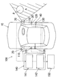
- FIG. 1 schematically shows a state in which the occupant restraint system 100 of the present embodiment is mounted on a vehicle 10 on which a vehicle occupant rides.
- a vehicle 10 as a “vehicle” in the present invention is not particularly shown, but includes a large number of vehicle constituent members constituting the vehicle, an engine traveling system that is a system involved in the traveling of the engine and the vehicle, and electric parts used in the vehicle.
- An electric system which is a system involved, an engine running system, a drive control means for controlling the driving of the electric system, and the like are provided.
- This occupant restraint system 100 is a system that performs control to quickly restrain a vehicle occupant based on information on the side collision in the event of a side collision of the vehicle 10. As shown in FIG. 1, the occupant restraint system 100 includes a camera 110, a side collision sensor 120, an acceleration sensor 130, an ECU 140, and an airbag module 150.
- the camera 110 is typically a camera for image detection (for example, a monocular camera such as a CMOS or a CCD) arranged toward the side of the vehicle.
- This camera 110 has a function of detecting an image of a collision object P located on the side of the vehicle 10, particularly an image of a collision object (also referred to as “obstacle”) involved in a side collision of the vehicle 10.
- the cameras 110 are preferably mounted on the left and right door mirror portions 20 of the vehicle 10, respectively.
- the camera 110 disposed on the door mirror 20 on the right side of the vehicle can detect an image of the collision object P in the detection region A in FIG.
- An image detected by the camera 110 is transmitted to an image processing ECU 141 described later in the ECU 140.
- this camera 110 is also used as a camera used for another purpose, in order to reduce costs, for example, a plurality of cameras (for example, front grille At least one of cameras installed in various places on the side mirror and the rear roof can be used.
- the camera 110 here corresponds to the “camera for image detection” in the present invention.
- the side collision sensor 120 is disposed in a partition area defined by a door outer panel and a door inner panel of the vehicle door 30.
- the side collision sensor 120 determines the amount of deformation at the time of a side collision of a door outer panel or a construction member (also referred to as “door beam” or “reinforcing member”) of the partition area between a predetermined object to be detected. This is a detection sensor that detects a change in distance.
- Information detected by the side collision sensor 120 is transmitted to an airbag module ECU 142 described later in the ECU 140.
- the side collision sensor 120 is preferably attached to each of a door beam or a reinforcing member typically attached to the left and right vehicle doors.
- the side collision sensor 120 here corresponds to the “side collision sensor” and “coil sensor” in the present invention.
- another detection sensor for detecting information related to a side collision can be appropriately mounted on a vehicle body side member such as a vehicle door, a rim, or a pillar.
- the acceleration sensor 130 is disposed on a vehicle body component of the vehicle 10.
- the acceleration sensor 130 is an acceleration sensor that detects acceleration information related to acceleration in the three-axis (X-axis, Y-axis, and Z-axis) directions that act on the vehicle 10 during a side collision.
- the acceleration information detected by the acceleration sensor 130 is transmitted to an airbag module ECU 142 described later in the ECU 140.
- the acceleration sensor 130 is preferably mounted on each of the left and right B pillars 40 of the vehicle.
- the acceleration sensor 130 can detect an operation amount (displacement acceleration, displacement speed, displacement distance) related to the operation at the time of a side collision of the vehicle 10, and the “operation amount detection unit” and “acceleration sensor” in the present invention. It corresponds to.
- the ECU 140 includes an image processing ECU 141 and an airbag module ECU 142.
- Each ECU includes a CPU (arithmetic processing unit), an input / output device, a storage device, a driving device, a peripheral device, and the like.
- the ECU 140 may be a part of a control unit as a drive control device (corresponding to the “drive control device” in the present invention) that controls the engine running system and the electrical system of the vehicle.
- a system constituted by the ECU 140, the camera 110, the side collision sensor 120, and the acceleration sensor 130 is a collision determination system that determines information related to a side collision of the vehicle.
- the “collision determination system” and “ “Collision determination device” is configured.
- the image processing ECU 141 is a processing unit that performs image processing of an image detected by the camera 110. Specifically, a first determination process for determining the shape or type of the collision target P of the side collision of the vehicle 10 based on the image detected by the camera 110, or the collision target of the vehicle 10 before the side collision.
- the image processing ECU 141 executes a second determination process for determining a collision predicted portion where a collision of the object P is predicted.
- a determination mode for determining whether an image of the detected collision object P is a predetermined obstacle, for example, a pole-shaped object such as a utility pole, or detection The judgment mode etc.
- the image processing ECU 141 referred to here determines the shape of the collision target P involved in the side collision of the vehicle 10 based on the image detected by the camera 110, and also determines the shape of the vehicle 10 based on the image detected by the camera 110.
- a determination processing unit that determines a predicted collision portion of the collision target P, and constitutes a “determination processing unit” or a “second determination processing unit” in the present invention.
- the air bag module ECU 142 functions to determine the occurrence of an actual side collision of the vehicle 10 based on the information detected by the side collision sensor 120, while the side surface based on the acceleration information detected by the acceleration sensor 130. It fulfills the function of deriving the displacement speed (also referred to as “collision speed”) of the vehicle body at the time of collision. Although details will be described later, the airbag module ECU 142 further has a function of setting a threshold relating to the displacement speed of the vehicle body at the time of a side collision, based on the processing results of the first processing and the second processing described above, and A function of outputting a drive control signal to the airbag module 150 is achieved based on the processing results of the first process and the second process. Airbag module ECU142 here comprises the "threshold setting part" and the "control part” in this invention.
- the airbag module 150 includes at least an airbag and a gas supply device.
- the airbag is a member that is formed into a bag shape by a fabric and that can be inflated and contracted.
- the gas supply device is activated based on the drive control signal output from the airbag module ECU 142 of the ECU 140, the airbag is deployed and inflated into the occupant restraint region by the gas supply from the gas supply device.
- the airbag module 150 is an airbag device in which an occupant-restraining airbag is appropriately accommodated in a seat, a pillar, an upper roof rail, or the like.
- the airbag module 150 here functions as a device that restrains the vehicle occupant during a side collision of the vehicle, and corresponds to the “occupant restraint device” in the present invention.
- the occupant restraint device controlled by the drive control signal from the airbag module ECU 142 is replaced with or in addition to the airbag module 150, and an occupant restraint device different from the airbag module 150 is used. It is possible to use.
- an occupant restraint device different from the airbag module 150 an occupant restraint device such as a seat belt device, a notification device that performs display output or voice output to perform notification of a side collision, or the like can be used.
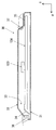
- FIG. 2 shows a basic structure of the side collision sensor 120 of the present embodiment
- FIG. 3 shows a sectional structure of the vehicle door 30 on which the side collision sensor 120 in FIG. 2 is mounted. It is shown schematically.
- the direction of arrow F indicates the front of the vehicle (forward direction)
- the direction of arrow I indicates the interior of the vehicle (vehicle compartment direction).
- the side collision sensor 120 of the present embodiment is a coil sensor in which a coil part 121 in which a magnetic sensor coil is wound in an annular shape one or more times in a coil housing 122 is accommodated.
- the coil part 121 is configured to extend in parallel with the metal detection object, and typically, the detection surface of the metal detection object 123 and the extension plane of the coil part 121 are generally approximately. It is preferable to arrange the side collision sensor 120 so as to be parallel. If necessary, the side collision sensor 120 may be arranged so that the detection surface of the detection object 123 and the extending plane of the coil portion 121 are relatively inclined at a predetermined inclination angle.
- an alternating current (sine wave current) is passed through the magnetic sensor coil of the coil unit 121 by driving an alternating current power supply device (not shown), and an alternating magnetic field is applied to the surrounding detected body 123 (conductor or magnetic body).
- An eddy current is generated in the detected object 123 by the law of electromagnetic induction. This eddy current also generates a magnetic field, and a part of the magnetic field crosses the magnetic sensor coil.
- the magnetic sensor coil adds the magnetic flux caused by the eddy current flowing through the detected object 123 to the magnetic flux caused by the current passed through the AC power supply device, and an induced voltage is generated in the magnetic sensor coil of the coil section 121 by these magnetic fluxes. Will be.
- the side collision sensor 120 can detect the distance to the detected object 123 based on the change in the current flowing in the magnetic sensor coil at this time. Thereby, based on the current change when the magnetic sensor coil is energized, the deformation amount (the deformation amount of the door outer panel 31) related to the vehicle door 30 at the time of the side collision of the vehicle 10 is detected as the change in the distance from the detected object 123.
- the detection object 123 is a detection object of the coil sensor, and is configured as a conductor or a magnetic material including, for example, steel, aluminum, ferrite, and the like. In particular, aluminum has high conductivity, and a large eddy current flows through the coil sensor.
- the detection object 123 is configured using a metal containing aluminum, which is advantageous in improving detection sensitivity.
- a side collision sensor 120 coil sensor
- Such a side collision sensor 120 that uses a coil to detect a metal detection object is a non-contact type, is resistant to impact, does not react to impact, and is not easily affected by the environment. Therefore, it is effective to ensure a desired detection accuracy regarding the side collision.
- the vehicle door 30 of the vehicle 10 is connected to a vehicle main body 37 via a door hinge 36.
- the vehicle door 30 includes a door outer panel 31 that forms an outer wall of the vehicle, and a door inner panel 32 that forms an inner wall of the vehicle.
- the vehicle door 30 may be a front seat door installed between the A pillar and the B pillar of the vehicle 10, or may be a rear seat door installed between the B pillar and the C pillar.
- a metal door beam 124 is installed in a partition region 33 partitioned by the door outer panel 31 and the door inner panel 32.
- the door outer panel 31, the door inner panel 32, and the partition area 33 here correspond to the “door outer panel”, “door inner panel”, and “partition area” in the present invention, respectively.
- the door beam 124 is a cylindrical, rod-shaped or columnar member that extends in the longitudinal direction of the vehicle.
- One end of the door beam 124 is fixed to the vehicle main body 37 via the vehicle front side bracket 34, and the other end is fixed to the vehicle main body 37 via the vehicle rear side bracket 35.
- the door beam 124 has both ends corresponding to the brackets 34 and 35 as fixed ends, and is between the door front end portion (vehicle front side bracket 34) and the door rear end portion (vehicle rear side bracket 35) in the vehicle longitudinal direction. It is erected in a long shape.
- the side collision sensor 120 having the above-described configuration is attached to a predetermined attachment region that faces the facing surface on the door inner panel 32 side (the detection target surface of the detection target 123) among the portions of the door beam 124.
- the side collision sensor 120 may be provided directly on the door beam 124 itself, or may be provided on another member fixed to the door beam 124. Or the structure by which the side collision sensor 120 is mounted
- FIG. 4 shows a flowchart relating to the airbag module control of the present embodiment.
- the control content shown in this flowchart is executed in cooperation by the image processing ECU 141 and the airbag module ECU 142.
- the airbag module control shown in FIG. 4 can be used.
- the image processing ECU 141 constantly monitors via the camera 110 in step S10. Thereby, when the collision target P exists in the detection area (detection area A in FIG. 1) on the side of the vehicle, an image of the collision target P is detected by the camera 110.
- step S11 the image processing ECU 141 determines whether or not the image of the collision target P detected by the camera 110 is that of a pole-shaped (bar-shaped) target (the aforementioned “first determination”). Equivalent to "processing”). Thereby, it is determined whether or not the image of the collision target P is that of a pole-shaped target.
- the first mode for determining whether or not the image of the collision target P detected by the camera 110 is that of a pole-shaped target the image of the collision target P detected by the camera 110 is A second mode for determining whether the object is a pole-shaped object or a barrier-shaped (planar) object, and the image of the collision object P detected by the camera 110 is a pole-shaped object.
- One of the third aspects of determining whether the object is a thing of a thing, a thing of a barrier-like object, or a thing different from a pole-like object and a barrier-like object
- One can be adopted.
- step S11 the image processing ECU 141 determines that the image of the collision target P detected by the camera 110 is that of a pole-shaped target (YES in step S11).
- the image processing ECU 141 proceeds to step S12. That is, if it is determined that the image of the collision object P detected by the camera 110 is not that of a pole object (NO in step S11), the process proceeds to step S16.
- step S12 and step S16 the image processing ECU 141 predicts the collision of the collision object P in the vehicle 10 before the side collision based on the image of the collision object P detected by the camera 110. (Corresponding to the aforementioned “second determination process”). Thereby, it is determined whether or not the collision predicted part of the collision target P is the vehicle door 30. If the image processing ECU 141 determines that the collision predicted part of the collision target P is the vehicle door 30 (YES in step S12 to step S16), the image processing ECU 141 proceeds to step S13 to step S17. In the case of NO in steps S12 to S16, the process is returned to step S10.
- step S13 and step S17 the airbag module ECU 142 determines whether or not the collision target actually collides with the vehicle 10 based on the detection information from the side collision sensor 120. If the air bag module ECU 142 determines that the object has actually collided with the vehicle 10 (YES in step S13 to step S17), the air bag module ECU 142 proceeds to step S14 to step S18. If it is determined that the object does not actually collide with the vehicle 10 (the collision is avoided) (NO in steps S13 to S17), the process returns to step S10.
- the door outer panel 31 of the vehicle door 30 shown in FIG. 3 receives an impact from the outside of the vehicle (downward in FIG. 3), and the inside of the vehicle (FIG. 3) (also referred to as “deformation” or “movement”).
- the door outer panel 31 is displaced inward of the vehicle due to a side collision with the object to be collided, and accordingly, the door beam 124 pressed through the door outer panel 31 bends inward of the vehicle.
- the side collision sensor 120 is displaced inward of the vehicle while approaching the detected body (opposing surface) on the door inner panel 32 side.
- the coil portion 121 constituting the side collision sensor 120 detects a change in the distance from the detected object (opposing surface) on the door inner panel 32 side configured as a metal body as described above. Based on the change, the airbag module ECU 142 detects a side collision of the vehicle 10.
- step S14 the image processing ECU 141 transmits recognition information indicating that the collision target P is a pole-shaped target to the airbag module ECU 142, and then proceeds to step S15.
- step S18 the image processing ECU 141 transmits recognition information indicating that the collision target P is not a pole-shaped target to the airbag module ECU 142, and then proceeds to step S19.
- step S15 the airbag module ECU 142 uses the pole collision threshold corresponding to the case where the collision object P is a pole-shaped object, and controls the airbag module 150 in a control mode based on the pole collision threshold.
- step S19 the airbag module ECU 142 uses the normal collision threshold corresponding to the collision object P other than the pole-shaped object, and controls the airbag module 150 in a control mode based on the normal collision threshold.
- This normal collision threshold value can also be set as a barrier collision threshold value corresponding to the case where the collision object P is a barrier-shaped barrier object.
- step S19 described above the airbag module ECU 142 sends a drive control signal to the airbag module 150 when the displacement speed (also referred to as “collision speed”) V of the vehicle 10 during a side collision exceeds a predetermined threshold value Va. Output.
- the airbag is deployed and inflated in the occupant restraint area to restrain the vehicle occupant.
- the control mode from step S16 to step S19 here corresponds to the “first control mode” in the present invention.
- step S15 the airbag module ECU 142 controls the airbag module 150 to drive when the displacement speed V of the vehicle 10 at the time of a side collision exceeds a threshold value Vb ( ⁇ Va) smaller than the threshold value Va. Output a signal.
- the airbag module ECU 142 changes the threshold value relating to the displacement speed V for driving the airbag module 150 in accordance with the shape or type of the collision object P.
- the threshold value is set to be relatively lower than that in the case of other collision objects, for example, a barrier-shaped barrier-shaped object.
- the control mode from step S12 to step S15 here corresponds to the “second control mode” in the present invention.
- the airbag module ECU 142 determines the threshold value Va (the “first threshold value in the present invention”) when the collision target P is other than the pole-shaped target.
- the threshold value Vb (corresponding to the “second threshold value” in the present invention) is employed when the collision object P is a pole-shaped object.
- the airbag module ECU 142 is configured such that the collision predicted portion is the vehicle door 30 and the collision target P is other than the pole-shaped target.
- a drive control signal is output to the airbag module 150 on the condition that the displacement speed V of the vehicle 10 exceeds the threshold value Va.
- the airbag module ECU 142 is configured such that when the collision prediction site is the vehicle door 30 and the collision target P is a pole-shaped target, As the second control mode, a drive control signal is output to the airbag module 150 on condition that the displacement speed V of the vehicle 10 exceeds the threshold value Vb.
- the airbag module ECU 142 By setting the threshold value for outputting the drive control signal to the bag module 150 to be lowered, it is possible to thoroughly restrain the vehicle occupant by the airbag module 150. Moreover, it is predicted that the collision target P will collide with the vehicle door 30 by the image processing ECU 141 by providing a step of determining a predicted collision part of the vehicle 10 where the collision of the collision target P is predicted before the side collision. Only when this is done, the airbag module ECU 142 controls the driving of the airbag module 150, so that the reliability of the occupant restraint control can be improved.
- step S12 and step S16 in FIG. 4 it is possible to omit the step (step S12 and step S16 in FIG. 4) of determining a predicted collision portion of the vehicle 10 where the collision of the collision object P is predicted before the side collision. is there.
- the airbag module ECU 142 sets the vehicle as the first control mode when the collision target P is other than the pole-shaped target.
- a drive control signal is output to the airbag module 150 on condition that the displacement speed V of 10 exceeds the threshold value Va.
- the airbag module ECU 142 sets the displacement speed of the vehicle 10 as the second control mode when the collision target P is a pole-shaped target.
- a drive control signal is output to the airbag module 150 on the condition that V exceeds the threshold value Vb.
- the control of the airbag module 150 that restrains a vehicle occupant using an airbag as the occupant restraint device has been described.
- the occupant restraint device is replaced with or added to the airbag module 150.
- an occupant restraint device such as a seat belt device that restrains the chest and abdomen of the occupant seated on the vehicle seat via the seat belt can be used.
- the configuration of the occupant restraint system to be mounted on the automobile has been described.
- the present invention is applied to the configuration of the occupant restraint system to be mounted on various vehicles such as cars, trains, buses, and trucks. Can be applied.
Abstract
【課題】車両の側面衝突の際、車両乗員を適正に拘束するのに有効な技術を提供する。 【解決手段】車両に搭載される乗員拘束システム100は、カメラ110、側突センサ120、加速度センサ130、ECU140及びエアバッグモジュール150を有している。ECU140は、車両10の側面衝突に関与する衝突対象物Pがポール状対象物である場合とそれ以外の場合とで、車両10の側面衝突時の衝突速度の閾値設定を変更し、設定した当該閾値に基づいてエアバッグモジュール150を制御する。
Description
本発明は、車両の衝突態様を判定する技術に関するものである。
従来、車両事故の際の衝突発生を検出する種々の車両衝突センサが知られている。例えば、下記特許文献1には、車両の側面衝突の際に作動するGセンサや接触センサによって、側面衝突を検出するシステムが開示されている。ところで、車両事故の際、エアバッグモジュールなどの乗員拘束システムによって車両乗員を拘束するこの種のシステムにおいては、乗員拘束性向上を図るべく車両衝突発生を迅速に検出することが可能な高度な検出技術が望まれている。とりわけ、下記特許文献1に記載のような側面衝突に関しては、車両乗員と衝突物との間に車両ドアが介在するのみであり、また、電柱や立ち木などのポール状の衝突対象物が車両ドアに側面衝突するポール衝突の場合には、車両ドアの車両内方への侵入速度が速いことから、側面衝突態様を前方衝突時よりも短時間で判定することが必要とされる。また、衝突対象物がポール状の衝突対象物である場合には、衝突対象物が壁や別の車両などのバリア状の衝突対象物である場合に比して、側面衝突時に車両乗員が受ける影響の度合いが高いことが知られており、衝突対象物の種類に応じて側面衝突時の車両乗員の拘束態様を適正に制御する技術が要請される。
そこで、本発明は、かかる点に鑑みてなされたものであり、車両の側面衝突の際、車両乗員を適正に拘束するのに有効な技術を提供することを課題とする。
前記課題を解決するために、本発明が適用される。本発明は、典型的には自動車において発生した側面衝突に関する情報を判定する技術に対し適用することができるが、自動車以外の車両において発生した側面衝突に関する情報を検出する技術に対しても同様に、本発明を適用することが可能である。ここでいう「車両」には、自動車、電車、バス、トラック等の各種の車両が包含される。
本発明にかかる衝突判定システムは、車両に搭載されるシステムであって、カメラ、側突センサ、動作量検出部、判定処理部、閾値設定部及び制御部を含む。これら各構成要素のうち、判定処理部、閾値設定部及び制御部は、それぞれ個別の処理要素としてもよいし、或いは単一の処理要素としてもよい。
カメラは、車両の車両側方に向けて配設される画像検出用のカメラである。このカメラとして、典型的には、CMOS、CCDなどの単眼カメラや、ステレオカメラを用いることができる。また、このカメラは、衝突判定システム専用のカメラとしてもよいし、別の用途に使用されるカメラと兼用してもよい。別の用途に使用されるカメラと兼用する場合には、コスト低減を図るべく、例えば車両の駐車操作をアシストするパーキングアシストシステムに使用される複数のカメラ(例えばフロントグリル・サイドミラー・リアルーフの各所に設置されたカメラ)のうちの少なくとも1つを用いることができる。
側突センサは、車両ドアのドアアウタパネルとドアインナパネルとで区画される区画領域に配設され、車両の側面衝突を検知するセンサである。この側突センサとして典型的には、金属製の被検出体に対向して配設された磁気センサコイルを有するコイルセンサや、車両ドア内の圧力変化によって車両ドアの変形(つぶれ)を検知する圧力センサを用いることができる。
動作量検出部は、車両の側面衝突時の動作に関する動作量を検出する検出部である。ここでいう「車両の側面衝突時の動作に関する動作量」とは、側面衝突時の車両の変位加速度、変位速度、変位距離などを広く包含する主旨である。判定処理部は、カメラが検出した画像に基づいて、車両の側面衝突に関与する衝突対象物の形状を判定する処理部である。閾値設定部は、判定処理部によって衝突対象物がポール状対象物以外であると判定された場合に動作量に関する閾値を第1の閾値に設定する一方、判定処理部によって衝突対象物がポール状対象物であると判定された場合に動作量に関する閾値を第1の閾値を下回る第2の閾値に設定する設定部である。
制御部は、第1及び第2の制御モードを少なくとも有する。この制御部は、第1及び第2の制御モードに加えて、更なる制御モードを有してもよい。ここで、第1の制御モードは、側突センサによって車両の側面衝突が検知されたとき、判定処理部の判定結果に基づいて衝突対象物がポール状対象物以外である場合に、動作量検出部において検出された動作量が閾値設定部で設定された第1の閾値を上回ることを条件として車両乗員を拘束する乗員拘束装置に対し駆動制御信号を出力する制御モードである。一方、第2の制御モードは、側突センサによって車両の側面衝突が検知されたとき、判定処理部の判定結果に基づいて衝突対象物がポール状対象物である場合に、動作量検出部において検出された動作量が閾値設定部で設定された第2の閾値を上回ることを条件として乗員拘束装置に対し駆動制御信号を出力する制御モードである。ここでいう「ポール状対象物」とは、棒状の衝突対象物を広く含む主旨であり、典型的には電柱や立ち木などがポール状対象物に相当する。また、ポール状対象物以外の衝突対象物として、典型的には壁や別の車両など平面状のバリア状対象物が挙げられる。なお、この制御部は、当該衝突判定システムの制御専用としてもよいし、或いは車両のエンジン走行系統や電装系統を駆動制御する手段と兼用してもよい。
本発明にかかる衝突判定システムの上記構成によれば、車両の側面衝突時の動作に関する動作量の閾値設定を衝突対象物の形状ないし種類に応じて変更し、設定した当該閾値に基づいて乗員拘束装置を駆動制御することによって、側面衝突時に車両乗員が受ける影響の度合いがとりわけ高いポール衝突に有効に対処することができ、以って車両の側面衝突の際、車両乗員を適正に拘束することが可能となる。
また、本発明にかかる別の形態の衝突判定システムは、車両に搭載されるシステムであって、カメラ、側突センサ、動作量検出部、判定処理部、第2の判定処理部、閾値設定部及び制御部を含む。これらの各構成要素のうち、カメラ、側突センサ、動作量検出部及び判定処理部に関しては、前述と同様の構成である。またこれら各構成要素のうち、判定処理部、第2の判定処理部、閾値設定部及び制御部は、それぞれ個別の処理要素としてもよいし、或いは単一の処理要素としてもよい。
第2の判定処理部は、カメラが検出した画像に基づいて、車両のうち衝突対象物の衝突予測部位を判定する処理部である。制御部は、第1及び第2の制御モードを少なくとも有する。この制御部は、第1及び第2の制御モードに加えて、更なる制御モードを有してもよい。ここで、第1の制御モードは、側突センサによって車両の側面衝突が検知されたとき、第2の判定処理部の判定結果に基づいて衝突予測部位が車両ドアであり、且つ判定処理部の判定結果に基づいて衝突対象物がポール状対象物以外である場合に、動作量検出部において検出された動作量が閾値設定部で設定された第1の閾値を上回ることを条件として車両乗員を拘束する乗員拘束装置に対し駆動制御信号を出力する制御モードである。一方、第2の制御モードは、側突センサによって車両の側面衝突が検知されたとき、第2の判定処理部の判定結果に基づいて衝突予測部位が車両ドアであり、且つ判定処理部の判定結果に基づいて衝突対象物がポール状対象物である場合に、動作量検出部において検出された動作量が閾値設定部で設定された第2の閾値を上回ることを条件として乗員拘束装置に対し駆動制御信号を出力する制御モードである。この制御部は、第2の判定処理部の判定結果に基づいて衝突予測部位が車両ドアでない場合、例えば衝突予測部位が車両ドア以外の部位である場合や、衝突対象物の衝突自体が回避された場合には、第1の閾値や第2の閾値とは別の閾値に基づいて、乗員拘束装置を駆動制御することができる。なお、この制御部は、当該衝突判定システムの制御専用としてもよいし、或いは車両のエンジン走行系統や電装系統を駆動制御する手段と兼用してもよい。
本発明にかかる別の形態の衝突判定システムの上記構成によれば、車両の側面衝突時の動作に関する動作量の閾値設定を衝突対象物の形状ないし種類に応じて変更し、設定した当該閾値に基づいて乗員拘束装置を駆動制御することによって、側面衝突時に車両乗員が受ける影響の度合いがとりわけ高いポール衝突に有効に対処することができ、以って車両の側面衝突の際、車両乗員を適正に拘束することが可能となる。更に、第2の判定処理部の判定結果を制御部の制御に反映させることによって、衝突対象物が車両ドアに衝突することが予測された場合にのみ、乗員拘束装置を駆動制御するため、乗員拘束制御の信頼性向上を図ることが可能となる。
また、本発明にかかる更なる形態の衝突判定システムでは、前記の判定処理部は、衝突対象物がポール状対象物以外である場合に、当該衝突対象物がバリア状対象物であると判定する構成であるのが好ましい。ここでいう「バリア状対象物」とは、平面状の衝突対象物を広く含む主旨であり、典型的には壁や別の車両などがバリア状対象物に相当する。これにより、側面衝突時に車両乗員が受ける影響の度合いが相対的に高いポール衝突の場合の第1の閾値と、側面衝突時に車両乗員が受ける影響の度合いが相対的に低いバリア衝突の場合の第2の閾値が設定される。このような構成によれば、衝突対象物がポール状対象物であるかバリア状対象物であるかに応じて、乗員拘束装置を適正に制御することが可能となる。
また、本発明にかかる更なる形態の衝突判定システムでは、前記の動作量検出部は、車両に装着され当該車両に作用する加速度情報を検出する加速度センサであり、当該加速度センサによって検出された加速度情報に基づいて、車両の側面衝突時の動作に関する衝突速度を検出する構成であるのが好ましい。このような構成によれば、車両の側面衝突時の動作に関する動作量のうち、特に衝突速度に関する閾値を衝突対象物の形状に応じて設定可能とした衝突判定システムが提供される。
また、本発明にかかる更なる形態の衝突判定システムでは、前記の側突センサは、車両ドアのドアアウタパネルとドアインナパネルとで区画される区画領域に介在する金属製の被検出体に対向して配設された磁気センサコイルを有するコイルセンサであり、磁気センサコイルの通電時における電流変化に基づいて、車両の側面衝突時の車両ドアに関する変形量を被検出体との間の距離変化として検出する構成であるのが好ましい。この場合、金属製の被検出体は、その全部または一部が、例えば鋼、銅、アルミニウム、フェライトなどを含む、導電体ないし磁性体として構成される。ここでいう「車両ドアに関する変形量」には、車両ドアのドアアウタパネルの変形量や、当該ドアアウタパネルの変形に伴って変形する部材の変形量などが広く包含される。このコイルセンサは、典型的には車両ドアのドアアウタパネルとドアインナパネルとで区画される区画領域において、車両ドア側部材に取り付けられる部材である。またここでいう「車両ドア側部材」としては、車両ドアのドア前端部とドア後端部との間に長尺状に架設され、側面衝突時に前記ドアアウタパネルの変位に伴って車両内方へと撓み動作する架設部材(「ドアビーム」或いは「補強部材」ともいう)、ドアフレーム、ドアインナパネル等、ドアアウタパネルとドアインナパネルとで区画される区画領域に面する各種の部材が採用され得る。このような構成によれば、コイルセンサは、非接触式であり、また衝撃にも強く衝撃に反応しない、環境に影響を受け難い等の特性を有することから、車両の側面衝突の検知精度を確保するのに有効である。
本発明にかかる乗員拘束システムは、前記の各衝突判定システムと、車両の側面衝突の際、衝突判定システムにおける判定結果に基づいて車両乗員を拘束する乗員拘束装置とを少なくとも備える。ここでいう「乗員拘束装置」として典型的には、乗員拘束領域に展開膨張するエアバッグによって乗員拘束を図るエアバッグ装置(エアバッグモジュール)や、車両シートに着座した乗員の胸部や腹部をシートベルトを介して拘束するシートベルト装置などの乗員拘束デバイスが挙げられる。この場合、乗員拘束装置としてエアバッグ装置を用いる場合には、エアバッグがシート、ピラー、上部ルーフレールなどに収容される形態のエアバッグ装置を採用することができる。このような構成によれば、前記の各衝突判定システムによる適正な判定によって乗員拘束装置を制御することが可能な乗員拘束システムが提供される。
本発明にかかる車両は、エンジン走行系統、電装系統、駆動制御装置、車両ドア、衝突判定装置及び乗員拘束装置を含む。エンジン走行系統は、エンジン及び車両の走行に関与する系統として機能する。電装系統は、車両に使われる電機部品に関与する系統として機能する。駆動制御装置は、エンジン走行系統及び電装系統の駆動制御を行う機能を有する装置として機能する。車両ドアは、側面衝突によりドアアウタパネルが変位する乗員乗降用のドアとして機能する。衝突判定装置は、車両ドアの側面衝突態様を判定する装置として機能する。この衝突判定装置が、前記の各衝突判定システムによって構成される。乗員拘束装置は、車両の側面衝突の際、衝突判定装置における判定結果に基づいて車両乗員を拘束する。このような構成によれば、前記の各衝突判定システムによる適正な判定によって制御される乗員拘束装置を備えた車両が提供される。
本発明によれば、特に車両の側面衝突に関与する衝突対象物がポール状対象物である場合とそれ以外の場合とで、車両の側面衝突時の動作に関する動作量の閾値設定を変更し、設定した当該閾値に基づいて乗員拘束装置を制御する構成を採用することによって、側面衝突時に車両乗員が受ける影響の度合いが高いポール衝突に有効に対処することができ、以って車両の側面衝突の際、車両乗員を適正に拘束することができる。
以下、図1~図4を参照しながら本発明における「乗員拘束システム」の一実施の形態である乗員拘束システム100について説明する。本実施の形態では、乗員拘束を行う乗員拘束装置として、事故発生の際に乗員拘束領域へのエアバッグの展開膨張が可能なエアバッグモジュールを採用している。このエアバッグモジュールは、運転席、助手席、後部座席等に対応して設置される。
本実施の形態の乗員拘束システム100が、車両乗員が乗車する車両10に搭載された様子が図1に模式的に示される。本発明における「車両」としての車両10は、特に図示しないものの、当該車両を構成する多数の車両構成部材、エンジン及び車両の走行に関与する系統であるエンジン走行系統、車両に使われる電機部品に関与する系統である電装系統、エンジン走行系統及び電装系統の駆動制御を行う駆動制御手段等を備えている。
この乗員拘束システム100は、車両10の側面衝突事故の際、当該側面衝突に関する情報に基づいて、車両乗員を速やかに拘束する制御を行なうシステムである。図1に示すように、この乗員拘束システム100は、カメラ110、側突センサ120、加速度センサ130、ECU140及びエアバッグモジュール150を有している。
カメラ110は、典型的には車両側方に向けて配設される画像検出用のカメラ(例えばCMOS、CCDなどの単眼カメラ)である。このカメラ110は、車両10の側方に位置する衝突対象物P、特には車両10の側面衝突に関与する衝突対象物(「障害物」ともいう)の画像を検出する機能を果たす。このカメラ110は、車両10の左右のドアミラー部20にそれぞれ搭載されるのが好ましい。例えば、車両右側のドアミラー部20に配設されたカメラ110は、図1中の検出領域Aにおいて衝突対象物Pの画像を検出することが可能である。このカメラ110によって検出された画像は、ECU140のうち後述する画像処理ECU141に伝送される。なお、このカメラ110を別の用途に使用されるカメラと兼用する場合には、コスト低減を図るべく、例えば車両の駐車操作をアシストするパーキングアシストシステムに使用される複数のカメラ(例えばフロントグリル・サイドミラー・リアルーフの各所に設置されたカメラ)のうちの少なくとも1つを用いることができる。ここでいうカメラ110が、本発明における「画像検出用のカメラ」に相当する。
側突センサ120は、詳細については後述するが、車両ドア30のドアアウタパネルとドアインナパネルとで区画される区画領域に配設される。この側突センサ120は、ドアアウタパネルや当該区画領域の架設部材(「ドアビーム」或いは「補強部材」ともいう)の側面衝突時における変形量を、予め規定された所定の被検出体との間の距離変化として検出する検出センサである。この側突センサ120によって検出された情報は、ECU140のうち後述するエアバッグモジュールECU142に伝送される。この側突センサ120は、典型的には左右の車両ドアに装着されたドアビーム或いは補強部材のそれぞれに装着されるのが好ましい。ここでいう側突センサ120が、本発明における「側突センサ」及び「コイルセンサ」に相当する。なお、この側突センサ120に加えて、側面衝突に関する情報を検出する更なる別の検出センサを、車両ドア、リム、ピラー等の車体側部材に適宜搭載することも可能である。
加速度センサ130は、車両10の車体構成部材に配設される。この加速度センサ130は、側面衝突時に車両10に作用する3軸(X軸、Y軸、Z軸)方向の加速度に関する加速度情報を検出する加速度センサである。この加速度センサ130によって検出された加速度情報は、ECU140のうち後述するエアバッグモジュールECU142に伝送される。この加速度センサ130は、典型的には車両の左右のBピラー40にそれぞれ装着されるのが好ましい。この加速度センサ130は、車両10の側面衝突時の動作に関する動作量(変位加速度、変位速度、変位距離)を検出することが可能であり、本発明における「動作量検出部」及び「加速度センサ」に相当する。
ECU140は、画像処理ECU141及びエアバッグモジュールECU142を有する。各ECUは、CPU(演算処理装置)、入出力装置、記憶装置、駆動装置、周辺装置等によって構成される。このECU140は、車両のエンジン走行系統や電装系統の制御を行なう駆動制御装置(本発明における「駆動制御装置」に相当する)としての制御ユニットの一部としてもよい。このECU140と、前記のカメラ110、側突センサ120及び加速度センサ130とによって構成されるシステムは、車両の側面衝突に関する情報を判定する衝突判定システムであり、本発明における「衝突判定システム」及び「衝突判定装置」を構成する。
画像処理ECU141は、カメラ110によって検出された画像の画像処理を行なう処理部である。具体的には、カメラ110によって検出された画像に基づいて、車両10の側面衝突の衝突対象物Pの形状ないし種類を判定する第1の判定処理や、側面衝突前において車両10のうち衝突対象物Pの衝突が予測される衝突予測部位を判定する第2の判定処理が、この画像処理ECU141によって実行される。第1の判定処理の具体例として、検出した衝突対象物Pの画像が予め既定された障害物、例えば電柱等のポール状の対象物のものであるか否かを判定する判定態様や、検出した衝突対象物Pの画像がポール状の対象物のものであるか、或いはバリア状の対象物のものであるか、更には別の対象物のものであるかを判定する判定態様等を採り得る。また第2の判定処理の具体例として、車両10のうち衝突対象物Pの衝突が予測される衝突部位が、車両ドア(車両乗員がいる部位)であると判定する判定態様等を採り得る。この画像処理ECU141における処理結果は、エアバッグモジュールECU142に伝送される。
ここでいう画像処理ECU141は、カメラ110が検出した画像に基づいて、車両10の側面衝突に関与する衝突対象物Pの形状を判定するとともに、カメラ110が検出した画像に基づいて、車両10のうち衝突対象物Pの衝突予測部位を判定する判定処理部であり、本発明における「判定処理部」ないし「第2の判定処理部」を構成する。
エアバッグモジュールECU142は、側突センサ120によって検出された情報に基づいて、車両10の実際の側面衝突の発生を判定する機能を果たす一方、加速度センサ130によって検出された加速度情報に基づいて、側面衝突時における車体の変位速度(「衝突速度」ともいう)を導出する機能を果たす。また詳細については後述するが、このエアバッグモジュールECU142は、更に前述の第1の処理及び第2の処理の処理結果に基づいて、側面衝突時における車体の変位速度に関する閾値を設定する機能、及び前述の第1の処理及び第2の処理の処理結果に基づいて、エアバッグモジュール150に駆動制御信号を出力する機能を果たす。ここでいうエアバッグモジュールECU142が、本発明における「閾値設定部」及び「制御部」を構成する。
エアバッグモジュール150は、特に図示しないものの、エアバッグ及びガス供給装置を少なくとも備える。当該エアバッグは、布地によって袋状に形成され、膨張及び収縮が可能な部材である。このエアバッグは、ECU140のエアバッグモジュールECU142から出力された駆動制御信号に基づいてガス供給装置が作動したとき、当該ガス供給装置からのガス供給によって乗員拘束領域に展開膨張する。これにより、車両事故の際、エアバッグモジュール150のエアバッグを介して車両乗員を拘束する制御が可能となる。このエアバッグモジュール150は、乗員拘束用のエアバッグがシート、ピラー、上部ルーフレールなどに適宜収容される形態のエアバッグ装置である。ここでいうエアバッグモジュール150は、車両の側面衝突の際、車両乗員を拘束する装置として機能し、本発明における「乗員拘束装置」に相当する。
なお、この乗員拘束システム100において、エアバッグモジュールECU142からの駆動制御信号によって制御される乗員拘束装置は、エアバッグモジュール150に代えて或いは加えて、エアバッグモジュール150とは別の乗員拘束装置を用いることが可能である。エアバッグモジュール150とは別の乗員拘束装置としては、シートベルト装置などの乗員拘束装置や、側面衝突の報知などを行うべく表示出力や音声出力を行う報知装置などを用いることもできる。
次に、上記側突センサ120の具体的な構成に関して図2及び図3を参照しつつ説明する。図2には、本実施の形態の側突センサ120の基本的な構造が示されており、また図3には、図2中の側突センサ120が搭載された車両ドア30の断面構造が模式的に示されている。なお、図3において、矢印F方向が車両前方(前進方向)を示し、矢印I方向が車両内方(車室方向)を示している。
図2に示すように、本実施の形態の側突センサ120は、コイルハウジング122内に磁気センサコイルが円環状に1または複数回巻かれたコイル部121を収容したコイルセンサである。コイル部121は、金属製の検出対象物と並行して延在する構成となっており、典型的には金属製の被検出体123の被検出面と、コイル部121の延在平面が概ね平行となるように、側突センサ120を配設するのが好ましい。必要に応じ、被検出体123の被検出面とコイル部121の延在平面が相対的に所定の傾斜角度によって傾斜するように側突センサ120を配設してもよい。そして、交流電源装置(図示省略)の駆動によって、このコイル部121の磁気センサコイルに交流電流(正弦波電流)が通電され、その周辺の被検出体123(導電体ないし磁性体)に交流磁場が与えられると、電磁誘導の法則によって被検出体123に渦電流が発生する。この渦電流によっても磁界を生じ、その磁界の一部が磁気センサコイルにも錯交する。結局、磁気センサコイルには、交流電源装置で流した電流による磁束に、被検出体123に流れた渦電流による磁束が加算され、これらの磁束によってコイル部121の磁気センサコイルに誘起電圧が発生することとなる。
側突センサ120は、このときに磁気センサコイルに流れる電流の変化に基づいて、被検出体123との間の距離を検出することが可能となる。これにより、磁気センサコイルの通電時における電流変化に基づいて、車両10の側面衝突時の車両ドア30に関する変形量(ドアアウタパネル31の変形量)が被検出体123との間の距離変化として検出されることとなる。この場合の被検出体123は、コイルセンサの検出対象物であり、例えば鋼、アルミニウム、フェライトなどを含む、導電体ないし磁性体として構成される。特に、アルミニウムは導電性が高く、コイルセンサによって大きな渦電流が流れるため、アルミニウムを含む金属を用いて被検出体123を構成することによって、検知感度を向上させるのに有利である。金属製の被検出体の検知にコイルを用いるこのような側突センサ120(コイルセンサ)は、非接触式であり、また衝撃にも強く衝撃に反応しない、環境に影響を受け難い等の特性を有することから、側面衝突に関する所望の検知精度を確保するのに有効である。
図3に示すように、車両10の車両ドア30は、ドアヒンジ36を介して車両本体37に連結されている。この車両ドア30は、車両の外側壁を形成するドアアウタパネル31、車両の内側壁を形成するドアインナパネル32を備える。この車両ドア30は、車両10のAピラーとBピラーとの間に設置される前席ドアとしてもよいし、或いはBピラーとCピラーとの間に設置される後席ドアとしてもよい。これらドアアウタパネル31及びドアインナパネル32によって区画される区画領域33には、金属製のドアビーム124が設置されている。ここでいうドアアウタパネル31、ドアインナパネル32及び区画領域33が、それぞれ本発明における「ドアアウタパネル」、「ドアインナパネル」及び「区画領域」に対応している。
ドアビーム124は、車両前後方向に長尺状に延在する筒状、棒状ないし柱状の部材である。このドアビーム124は、一端が車両前方側ブラケット34を介して車両本体37に固定される一方、他端が車両後方側ブラケット35を介して車両本体37に固定される。すなわち、このドアビーム124は、ブラケット34,35に対応する両端を固定端として、車両前後方向に関しドア前端部(車両前方側ブラケット34)とドア後端部(車両後方側ブラケット35)との間に長尺状に架設されている。
このドアビーム124の各部位のうち、ドアインナパネル32側の対向面(被検出体123の被検出面)に向かう所定の取付け領域に、前記構成の側突センサ120が取り付けられる。なお、この側突センサ120は、ドアビーム124自体に直接的に設けてもよいし、或いはドアビーム124に止着された別の部材に対して設けてもよい。或いは、ドアインナパネル32側に側突センサ120が装着される構成を採用することもできる。この場合には、ドアビーム124自体、或いはドアビーム124に止着された別の部材に、被検出体123の被検出面を設けるのが好ましい。
次に、上記構成の乗員拘束システム100の作用に関して図4を参照しつつ説明する。図4には、本実施の形態のエアバッグモジュール制御に関するフローチャートが示されている。なお、このフローチャートに示す制御内容は、画像処理ECU141及びエアバッグモジュールECU142により協働して実行される。
ここでは、車両10と衝突対象物(図1中の衝突対象物P)とが相対的に近接して実際の衝突に至る場合について考える。この場合、図4に示すエアバッグモジュール制御を用いることができる。このエアバッグモジュール制御では、まず画像処理ECU141が、ステップS10においてカメラ110を介して常時監視を行なう。これにより、車両側方の検出領域(図1中の検出領域A)に衝突対象物Pが存在する場合、この衝突対象物Pの画像がカメラ110によって検出される。
次に、画像処理ECU141が、ステップS11によって、カメラ110が検出した衝突対象物Pの画像がポール状(棒状)の対象物のものであるか否かを判定する(前述の「第1の判定処理」に相当する)。これにより、衝突対象物Pの画像がポール状の対象物のものであるか否かが判定される。なお、このステップS11では、カメラ110が検出した衝突対象物Pの画像がポール状対象物のものであるか否かを判定する第1の態様、カメラ110が検出した衝突対象物Pの画像がポール状対象物のものであるか、或いはバリア状(平面状)の対象物のものであるかを判定する第2の態様、更にはカメラ110が検出した衝突対象物Pの画像がポール状対象物のものであるか、或いはバリア状対象物のものであるか、或いはポール状対象物及びバリア状対象物とは別の対象物のものであるかを判定する第3の態様のうちの1つを採用することができる。
画像処理ECU141は、カメラ110が検出した衝突対象物Pの画像がポール状の対象物のものであると判定した場合(ステップS11のYESの場合)にはステップS12に処理をすすめ、そうでない場合、すなわちカメラ110が検出した衝突対象物Pの画像がポール状の対象物のものでないと判定した場合(ステップS11のNOの場合)にはステップS16に処理をすすめる。
ステップS12及びステップS16ではいずれも、画像処理ECU141が、カメラ110が検出した衝突対象物Pの画像に基づいて、側面衝突前において車両10のうち衝突対象物Pの衝突が予測される衝突予測部位を判定する(前述の「第2の判定処理」に相当する)。これにより、衝突対象物Pの衝突予測部位が車両ドア30であるか否かが判定される。画像処理ECU141は、衝突対象物Pの衝突予測部位が車両ドア30であると判定した場合(ステップS12ないしステップS16のYESの場合)には、ステップS13ないしステップS17に処理をすすめ、そうでない場合(ステップS12ないしステップS16のNOの場合)には、ステップS10に処理を戻す。
ステップS13及びステップS17ではいずれも、エアバッグモジュールECU142が、側突センサ120による検出情報に基づいて、衝突対象物が実際に車両10に衝突したか否かを判定する。エアバッグモジュールECU142は、当該対象物が実際に車両10に衝突したと判定した場合(ステップS13ないしステップS17のYESの場合)には、ステップS14ないしステップS18に処理をすすめ、そうでない場合、すなわち当該対象物が実際には車両10に衝突しなかった(衝突が回避された)と判定した場合(ステップS13ないしステップS17のNOの場合)には、ステップS10に処理を戻す。
なお、衝突対象物が実際に車両10に衝突した場合には、図3中に示す車両ドア30のドアアウタパネル31が車両外方(図3中の下方)から衝撃を受け、車両内方(図3中の上方)へと変位(「変形」ないし「移動」ともいう)する。このとき、ドアアウタパネル31は、衝突対象物との側面衝突によって車両内方へと変位し、これに伴ってドアアウタパネル31を介して押圧されたドアビーム124が車両内方へと撓み動作する。ドアビーム124のこの撓み動作の際、側突センサ120はドアインナパネル32側の被検出体(対向面)に近接しつつ車両内方へと変位する。これにより、側突センサ120を構成するコイル部121によって、前述のような金属体として構成されるドアインナパネル32側の被検出体(対向面)との間の距離変化が検出され、この距離変化に基づいてエアバッグモジュールECU142が車両10の側面衝突を検出することとなる。
ステップS14では、画像処理ECU141がエアバッグモジュールECU142に対し、衝突対象物Pがポール状の対象物であることを示す認識情報を伝送し、その後にステップS15に処理をすすめる。一方、ステップS18では、画像処理ECU141がエアバッグモジュールECU142に対し、衝突対象物Pがポール状の対象物でないことを示す認識情報を伝送し、その後にステップS19に処理をすすめる。
ステップS15では、エアバッグモジュールECU142は、衝突対象物Pがポール状の対象物である場合に対応したポール衝突用閾値を用い、このポール衝突用閾値に基づく制御態様でエアバッグモジュール150を制御する。一方、ステップS19では、エアバッグモジュールECU142は、衝突対象物Pがポール状の対象物以外に対応した通常衝突用閾値を用い、この通常衝突用閾値に基づく制御態様でエアバッグモジュール150を制御する。この通常衝突用閾値を、衝突対象物Pがバリア状のバリア状対象物である場合に対応したバリア衝突用閾値とすることもできる。
上記のステップS19では、エアバッグモジュールECU142は、側面衝突時における車両10の変位速度(「衝突速度」ともいう)Vが予め既定した閾値Vaを上回る場合に、エアバッグモジュール150に駆動制御信号を出力する。これにより、エアバッグが乗員拘束領域に展開膨張して車両乗員を拘束する。ここでいうステップS16からステップS19に至る制御モードが、本発明における「第1の制御モード」に相当する。
これに対し、上記のステップS15では、エアバッグモジュールECU142は、側面衝突時における車両10の変位速度Vが閾値Vaよりも小さい閾値Vb(<Va)を上回る場合に、エアバッグモジュール150に駆動制御信号を出力する。すなわち、本実施の形態では、エアバッグモジュールECU142が、エアバッグモジュール150を駆動する変位速度Vに関する閾値を、衝突対象物Pの形状ないし種類に応じて可変とするとともに、特に衝突対象物Pがポール状対象物である場合には、それ以外の衝突対象物、例えばバリア状のバリア状対象物である場合よりも相対的に低い閾値に設定することとしている。ここでいうステップS12からステップS15に至る制御モードが、本発明における「第2の制御モード」に相当する。
以上のように、本実施の形態では、エアバッグモジュールECU142は、変位速度Vの閾値設定に関し、衝突対象物Pがポール状対象物以外である場合に閾値Va(本発明における「第1の閾値」に相当する)を採用する一方、衝突対象物Pがポール状対象物である場合に閾値Vb(本発明における「第2の閾値」に相当する)を採用する。更に、このエアバッグモジュールECU142は、側突センサ120によって車両10の側面衝突が検知されたとき、衝突予測部位が車両ドア30であり、且つ衝突対象物Pがポール状対象物以外である場合に、第1の制御モードとして、車両10の変位速度Vが閾値Vaを上回ることを条件としてエアバッグモジュール150に駆動制御信号を出力する。また、このエアバッグモジュールECU142は、側突センサ120によって車両10の側面衝突が検知されたとき、衝突予測部位が車両ドア30であり、且つ衝突対象物Pがポール状対象物である場合に、第2の制御モードとして、車両10の変位速度Vが閾値Vbを上回ることを条件としてエアバッグモジュール150に駆動制御信号を出力する。
このような構成によれば、側面衝突時における車両10の変位速度Vが低速である場合であっても、衝突対象物Pがポール状のポール状対象物であるときには、エアバッグモジュールECU142がエアバッグモジュール150に駆動制御信号を出力する閾値を下げる設定を行なうことによって、エアバッグモジュール150による車両乗員の拘束徹底を図ることが可能となる。また、側面衝突前において車両10のうち衝突対象物Pの衝突が予測される衝突予測部位を判定するステップを設けることによって、画像処理ECU141により衝突対象物Pが車両ドア30に衝突することが予測された場合にのみ、エアバッグモジュールECU142がエアバッグモジュール150を駆動制御するため、乗員拘束制御の信頼性向上を図ることが可能となる。
(他の実施の形態)
なお、本発明は上記の実施の形態のみに限定されるものではなく、種々の応用や変形が考えられる。例えば、上記実施の形態を応用した次の各形態を実施することもできる。
なお、本発明は上記の実施の形態のみに限定されるものではなく、種々の応用や変形が考えられる。例えば、上記実施の形態を応用した次の各形態を実施することもできる。
上記実施の形態においては、側面衝突前において車両10のうち衝突対象物Pの衝突が予測される衝突予測部位を判定するステップ(図4中のステップS12及びステップS16)を省略することも可能である。この場合には、エアバッグモジュールECU142は、側突センサ120によって車両10の側面衝突が検知されたとき、衝突対象物Pがポール状対象物以外である場合に、第1の制御モードとして、車両10の変位速度Vが閾値Vaを上回ることを条件としてエアバッグモジュール150に駆動制御信号を出力する。また、エアバッグモジュールECU142は、側突センサ120によって車両10の側面衝突が検知されたとき、衝突対象物Pがポール状対象物である場合に、第2の制御モードとして、車両10の変位速度Vが閾値Vbを上回ることを条件としてエアバッグモジュール150に駆動制御信号を出力する。このような構成によっても、衝突対象物Pがポール状のポール状対象物であるときには、エアバッグモジュール150に駆動制御信号を出力する閾値を下げる設定を行なうことによって、エアバッグモジュール150による車両乗員の拘束徹底を図ることが可能となる。
また上記実施の形態では、側突センサ120として金属製の被検出体に対向して配設された磁気センサコイルを有するコイルセンサを用いる場合について記載したが、本発明ではコイルセンサにかえて、車両ドア内の圧力変化によって車両ドアの変形(つぶれ)を検知する圧力センサを用いることが可能である。
また上記実施の形態では、乗員拘束装置としてエアバッグを用いて車両乗員を拘束するエアバッグモジュール150の制御について記載したが、本発明では、乗員拘束装置として、エアバッグモジュール150に代えて或いは加えて、車両シートに着座した乗員の胸部や腹部をシートベルトを介して拘束するシートベルト装置などの乗員拘束デバイスを用いることができる。
また上記実施の形態では、自動車に装着される乗員拘束システムの構成について記載したが、自動車をはじめ、電車、バス、トラック等の各種の車両に装着される乗員拘束システムの構成に対し本発明を適用することができる。
10 車両
20 ドアミラー部
30 車両ドア
31 ドアアウタパネル
32 ドアインナパネル
33 区画領域
34 車両前方側ブラケット
35 車両後方側ブラケット
36 ドアヒンジ
37 車両本体
40 Bピラー
100 乗員拘束システム
110 カメラ
120 側突センサ
121 コイル部
122 コイルハウジング
123 被検出体
124 ドアビーム
130 加速度センサ(動作量検出部)
140 ECU
141 画像処理ECU(判定処理部、第2の判定処理部)
142 エアバッグモジュールECU(閾値設定部、制御部)
150 エアバッグモジュール(乗員拘束装置)
A 検出領域
P 衝突対象物
Va 閾値(第1の閾値)
Vb 閾値(第2の閾値)
Claims (6)
- 車両に搭載される衝突判定システムであって、
前記車両の車両側方に向けて配設される画像検出用のカメラと、
車両ドアのドアアウタパネルとドアインナパネルとで区画される区画領域に配設され、前記車両の側面衝突を検知する側突センサと、
前記車両の側面衝突時の動作に関する動作量を検出する動作量検出部と、
前記カメラが検出した画像に基づいて、前記車両の側面衝突に関与する衝突対象物の形状を判定する判定処理部と、
前記判定処理部によって前記衝突対象物がポール状対象物以外であると判定された場合に前記動作量に関する閾値を第1の閾値に設定する一方、前記判定処理部によって前記衝突対象物がポール状対象物であると判定された場合に前記動作量に関する閾値を前記第1の閾値を下回る第2の閾値に設定する閾値設定部と、
前記側突センサによって前記車両の側面衝突が検知されたとき、前記判定処理部の判定結果に基づいて前記衝突対象物がポール状対象物以外である場合に、前記動作量検出部において検出された動作量が前記閾値設定部で設定された前記第1の閾値を上回ることを条件として車両乗員を拘束する乗員拘束装置に対し駆動制御信号を出力する第1の制御モードと、前記側突センサによって前記車両の側面衝突が検知されたとき、前記判定処理部の判定結果に基づいて前記衝突対象物がポール状対象物である場合に、前記動作量検出部において検出された動作量が前記閾値設定部で設定された前記第2の閾値を上回ることを条件として前記乗員拘束装置に対し駆動制御信号を出力する第2の制御モードとを有する制御部と、
を備える構成であることを特徴とする衝突判定システム。 - 車両に搭載される衝突判定システムであって、
前記車両の車両側方に向けて配設される画像検出用のカメラと、
車両ドアのドアアウタパネルとドアインナパネルとで区画される区画領域に配設され、前記車両の側面衝突を検知する側突センサと、
前記車両の側面衝突時の動作に関する動作量を検出する動作量検出部と、前記カメラが検出した画像に基づいて、前記車両の側面衝突に関与する衝突対象物の形状を判定する判定処理部と、
前記カメラが検出した画像に基づいて、前記車両のうち前記衝突対象物の衝突予測部位を判定する第2の判定処理部と、
前記判定処理部によって前記衝突対象物がポール状対象物以外であると判定された場合に前記動作量に関する閾値を第1の閾値に設定する一方、前記判定処理部によって前記衝突対象物がポール状対象物であると判定された場合に前記動作量に関する閾値を前記第1の閾値を下回る第2の閾値に設定する閾値設定部と、
前記側突センサによって前記車両の側面衝突が検知されたとき、前記第2の判定処理部の判定結果に基づいて前記衝突予測部位が前記車両ドアであり、且つ前記判定処理部の判定結果に基づいて前記衝突対象物がポール状対象物以外である場合に、前記動作量検出部において検出された動作量が前記閾値設定部で設定された前記第1の閾値を上回ることを条件として車両乗員を拘束する乗員拘束装置に対し駆動制御信号を出力する第1の制御モードと、前記側突センサによって前記車両の側面衝突が検知されたとき、前記第2の判定処理部の判定結果に基づいて前記衝突予測部位が前記車両ドアであり、且つ前記判定処理部の判定結果に基づいて前記衝突対象物がポール状対象物である場合に、前記動作量検出部において検出された動作量が前記閾値設定部で設定された前記第2の閾値を上回ることを条件として前記乗員拘束装置に対し駆動制御信号を出力する第2の制御モードとを有する制御部と、
を備える構成であることを特徴とする衝突判定システム。 - 請求項1または2に記載の衝突判定システムであって、
前記動作量検出部は、前記車両に装着され当該車両に作用する加速度情報を検出する加速度センサを用いて構成され、当該加速度センサによって検出された加速度情報に基づいて、前記車両の側面衝突時の動作に関する衝突速度を検出する構成であることを特徴とする衝突判定システム。 - 請求項1または2に記載の衝突判定システムであって、
前記側突センサは、前記車両ドアのドアアウタパネルとドアインナパネルとで区画される区画領域に介在する金属製の被検出体に対向して配設された磁気センサコイルを有するコイルセンサとして構成され、前記磁気センサコイルの通電時における電流変化に基づいて、前記車両の側面衝突時の前記車両ドアに関する変形量を前記被検出体との間の距離変化として検出する構成であることを特徴とする衝突判定システム。 - 請求項1から4のうちのいずれか1項に記載の衝突判定システムと、
前記車両の側面衝突の際、前記衝突判定システムにおける判定結果に基づいて車両乗員を拘束する乗員拘束装置と、
を備える構成であることを特徴とする乗員拘束システム。 - エンジン走行系統と、
電装系統と、
前記エンジン走行系統及び電装系統の駆動制御を行う駆動制御装置と、
側面衝突によりドアアウタパネルが変位する乗員乗降用の車両ドアと、
前記車両ドアの側面衝突態様を判定する衝突判定装置と、
前記車両の側面衝突の際、前記衝突判定装置における判定結果に基づいて車両乗員を拘束する乗員拘束装置と、
を備え、
前記衝突判定装置は、請求項1から4のうちのいずれか1項に記載の衝突判定システムによって構成されていることを特徴とする車両。
Priority Applications (3)
| Application Number | Priority Date | Filing Date | Title |
|---|---|---|---|
| EP09831773.8A EP2371629B1 (en) | 2008-12-09 | 2009-10-26 | Collision determination system, occupant restraint system, and vehicle |
| US13/132,309 US8825305B2 (en) | 2008-12-09 | 2009-10-26 | Collision determination system, occupant restraint system, and vehicle |
| CN200980149549.4A CN102245441B (zh) | 2008-12-09 | 2009-10-26 | 碰撞判定系统、乘员限制系统、车辆 |
Applications Claiming Priority (2)
| Application Number | Priority Date | Filing Date | Title |
|---|---|---|---|
| JP2008313412A JP5329194B2 (ja) | 2008-12-09 | 2008-12-09 | 衝突判定システム、乗員拘束システム、車両 |
| JP2008-313412 | 2008-12-09 |
Publications (1)
| Publication Number | Publication Date |
|---|---|
| WO2010067667A1 true WO2010067667A1 (ja) | 2010-06-17 |
Family
ID=42242659
Family Applications (1)
| Application Number | Title | Priority Date | Filing Date |
|---|---|---|---|
| PCT/JP2009/068334 WO2010067667A1 (ja) | 2008-12-09 | 2009-10-26 | 衝突判定システム、乗員拘束システム、車両 |
Country Status (5)
| Country | Link |
|---|---|
| US (1) | US8825305B2 (ja) |
| EP (1) | EP2371629B1 (ja) |
| JP (1) | JP5329194B2 (ja) |
| CN (1) | CN102245441B (ja) |
| WO (1) | WO2010067667A1 (ja) |
Cited By (1)
| Publication number | Priority date | Publication date | Assignee | Title |
|---|---|---|---|---|
| CN102205855A (zh) * | 2011-01-21 | 2011-10-05 | 浙江吉利汽车研究院有限公司 | 一种充气式汽车车身纵梁 |
Families Citing this family (24)
| Publication number | Priority date | Publication date | Assignee | Title |
|---|---|---|---|---|
| US8820462B2 (en) * | 2011-05-11 | 2014-09-02 | Nissan Motor Co., Ltd. | Occupant restraint system and occupant restraint method |
| CN103085716A (zh) * | 2011-10-31 | 2013-05-08 | 鸿富锦精密工业(深圳)有限公司 | 交通意外防止系统及方法 |
| DE102012005075A1 (de) * | 2012-03-13 | 2013-09-19 | Gm Global Technology Operations, Llc | Verfahren zur Warnung vor einer möglichen Kollision eines Objektes mit einer Fahrzeugtür eines stehenden Kraftfahrzeuges |
| EP2679450B1 (en) | 2012-06-27 | 2016-07-20 | Volvo Car Corporation | System for protection of a vulnerable road user and method for operating the system |
| JP5905846B2 (ja) * | 2013-03-29 | 2016-04-20 | 株式会社日本自動車部品総合研究所 | 横断判定装置およびプログラム |
| WO2014171863A1 (en) * | 2013-04-17 | 2014-10-23 | Autoliv Development Ab | System for controlling the deployment of an external safety device |
| EP2821308B1 (en) * | 2013-07-03 | 2016-09-28 | Volvo Car Corporation | Vehicle system for control of vehicle safety parameters, a vehicle and a method for controlling safety parameters |
| KR102131448B1 (ko) * | 2013-11-29 | 2020-07-08 | 현대모비스 주식회사 | 자동차의 승객 보호장치 |
| EP2883756B1 (en) | 2013-12-12 | 2019-11-06 | Volvo Car Corporation | Safety system and method for operating a safety system of a vehicle |
| JP6685240B2 (ja) * | 2015-01-27 | 2020-04-22 | 株式会社半導体エネルギー研究所 | 乗員保護装置 |
| US9994184B2 (en) * | 2015-03-31 | 2018-06-12 | Ford Global Technologies, Llc | Vehicle side airbag with secondary chamber |
| CN105480184A (zh) * | 2015-12-28 | 2016-04-13 | 南京航空航天大学 | 一种汽车侧向撞击的保护机构及其控制方法 |
| US10026319B2 (en) * | 2015-12-30 | 2018-07-17 | Thunder Power New Energy Vehicle Development Limited | Collision warning system |
| JP6318183B2 (ja) * | 2016-01-20 | 2018-04-25 | 株式会社Subaru | 画像処理装置 |
| CN105654752B (zh) * | 2016-04-06 | 2018-06-29 | 河南理工大学 | 一种用于多个车辆的汽车行驶安全预警装置 |
| CN107839594B (zh) * | 2016-09-21 | 2020-10-13 | 奥迪股份公司 | 用于车辆的障碍检测装置和方法 |
| JP2018065482A (ja) | 2016-10-20 | 2018-04-26 | 本田技研工業株式会社 | 乗員保護装置 |
| JP6753324B2 (ja) * | 2017-01-25 | 2020-09-09 | トヨタ自動車株式会社 | 車両用乗員保護装置及び車両用乗員保護方法 |
| WO2018150010A1 (de) * | 2017-02-20 | 2018-08-23 | Thyssenkrupp Ag | Achsantriebseinheit mit induktivem ladeempfänger, antriebsachse und kraftfahrzeug |
| CN106864405B (zh) * | 2017-04-14 | 2018-04-13 | 吉林大学 | 一种基于碰撞形态预测的智能安全气囊装置主动调控方法 |
| CN111886631A (zh) * | 2018-03-15 | 2020-11-03 | 阿默尔·萨利赫阿塔拉拉赫阿塔拉拉赫 | 捕捉肇事逃逸-系统(char-s) |
| KR102656935B1 (ko) | 2019-07-08 | 2024-04-16 | 현대모비스 주식회사 | 에어백 제어 장치 및 방법 |
| US20210031714A1 (en) * | 2019-07-30 | 2021-02-04 | Zf Friedrichshafen Ag | Enhanced discrimination method and apparatus for controlling an actuatable protection device |
| CN111572485B (zh) * | 2020-04-29 | 2021-07-06 | 东风汽车集团有限公司 | 一种碰撞保护装置控制系统和控制方法 |
Citations (6)
| Publication number | Priority date | Publication date | Assignee | Title |
|---|---|---|---|---|
| JPH07172262A (ja) | 1993-12-22 | 1995-07-11 | Mitsubishi Motors Corp | 車両用エアーバッグ装置 |
| JPH11310095A (ja) * | 1998-02-24 | 1999-11-09 | Toyota Central Res & Dev Lab Inc | 車両用衝突判別装置 |
| JP2003261003A (ja) * | 1999-02-09 | 2003-09-16 | Toyota Motor Corp | 乗員保護装置の起動制御装置 |
| JP2004212281A (ja) * | 2003-01-07 | 2004-07-29 | Nissan Motor Co Ltd | 車両衝突状態検出装置 |
| JP2008037181A (ja) * | 2006-08-02 | 2008-02-21 | Takata Corp | 変位情報導出装置、乗員拘束システム、車両、変位情報導出方法 |
| JP2008247277A (ja) * | 2007-03-30 | 2008-10-16 | Takata Corp | 乗員拘束装置の制御方法及び乗員拘束装置 |
Family Cites Families (21)
| Publication number | Priority date | Publication date | Assignee | Title |
|---|---|---|---|---|
| US7481453B2 (en) | 1991-07-09 | 2009-01-27 | Automotive Technologies International, Inc. | Inflator system |
| DE69315653T2 (de) | 1992-09-21 | 1998-04-02 | Nec Corp | Unterscheidung eines Unfalls von einem Nicht-Unfall durch Analyse der beim Aufprall erzeugten Frequenzkomponenten der Beschleunigungmesswerte |
| JP3118980B2 (ja) | 1992-09-21 | 2000-12-18 | 日本電気株式会社 | 車両の衝突判定装置 |
| JPH0747915A (ja) | 1993-08-06 | 1995-02-21 | Toyota Motor Corp | 側面衝突用エアバッグ装置 |
| JP3013676B2 (ja) | 1993-10-25 | 2000-02-28 | トヨタ自動車株式会社 | 側面衝突用エアバッグ装置 |
| JP3750314B2 (ja) * | 1997-10-06 | 2006-03-01 | マツダ株式会社 | 車両のエアーバッグ装置 |
| US6561301B1 (en) | 1998-02-24 | 2003-05-13 | Kabushiki Kaisha Toyota Chuo Kenkyusho | Collision discriminating apparatus for vehicles |
| JP2000142310A (ja) | 1998-11-04 | 2000-05-23 | Toyota Motor Corp | 車両用側面衝突検知センサの取付構造 |
| JP3436185B2 (ja) | 1999-02-09 | 2003-08-11 | トヨタ自動車株式会社 | 乗員保護装置の起動制御装置 |
| JP2000233708A (ja) | 1999-02-15 | 2000-08-29 | Toyota Motor Corp | 側面衝突検知装置 |
| US6644688B1 (en) * | 1999-11-04 | 2003-11-11 | Automotive Systems Labortory, Inc. | Crash sensing system |
| JP3503549B2 (ja) * | 1999-11-18 | 2004-03-08 | トヨタ自動車株式会社 | サイドエアバッグ装置及びその制御方法 |
| JP5042475B2 (ja) * | 2005-07-27 | 2012-10-03 | タカタ株式会社 | 変位情報導出装置、乗員拘束システム、車両、変位情報導出方法 |
| JP4918981B2 (ja) | 2005-11-04 | 2012-04-18 | 株式会社デンソー | 車両用衝突判定装置 |
| JP2007137336A (ja) * | 2005-11-21 | 2007-06-07 | Denso Corp | 衝突検出装置及び保護装置 |
| JP4670709B2 (ja) | 2006-03-31 | 2011-04-13 | 株式会社デンソー | 車両用衝突検知システム |
| JP2008105634A (ja) | 2006-10-27 | 2008-05-08 | Toyota Motor Corp | 側面衝突検知装置 |
| JP2008137491A (ja) | 2006-12-01 | 2008-06-19 | Calsonic Kansei Corp | 車両用側面衝突検知装置 |
| JP2008195230A (ja) | 2007-02-13 | 2008-08-28 | Toyota Motor Corp | 側面衝突用エアバッグ制御装置 |
| JP5041868B2 (ja) | 2007-04-27 | 2012-10-03 | 本田技研工業株式会社 | 乗員拘束装置の起動システム |
| US8014921B2 (en) * | 2008-06-25 | 2011-09-06 | Ford Global Technologies, Llc | Ultrasonic sensor-based side impact sensing system |
-
2008
- 2008-12-09 JP JP2008313412A patent/JP5329194B2/ja not_active Expired - Fee Related
-
2009
- 2009-10-26 CN CN200980149549.4A patent/CN102245441B/zh not_active Expired - Fee Related
- 2009-10-26 WO PCT/JP2009/068334 patent/WO2010067667A1/ja active Application Filing
- 2009-10-26 EP EP09831773.8A patent/EP2371629B1/en not_active Not-in-force
- 2009-10-26 US US13/132,309 patent/US8825305B2/en active Active
Patent Citations (6)
| Publication number | Priority date | Publication date | Assignee | Title |
|---|---|---|---|---|
| JPH07172262A (ja) | 1993-12-22 | 1995-07-11 | Mitsubishi Motors Corp | 車両用エアーバッグ装置 |
| JPH11310095A (ja) * | 1998-02-24 | 1999-11-09 | Toyota Central Res & Dev Lab Inc | 車両用衝突判別装置 |
| JP2003261003A (ja) * | 1999-02-09 | 2003-09-16 | Toyota Motor Corp | 乗員保護装置の起動制御装置 |
| JP2004212281A (ja) * | 2003-01-07 | 2004-07-29 | Nissan Motor Co Ltd | 車両衝突状態検出装置 |
| JP2008037181A (ja) * | 2006-08-02 | 2008-02-21 | Takata Corp | 変位情報導出装置、乗員拘束システム、車両、変位情報導出方法 |
| JP2008247277A (ja) * | 2007-03-30 | 2008-10-16 | Takata Corp | 乗員拘束装置の制御方法及び乗員拘束装置 |
Non-Patent Citations (1)
| Title |
|---|
| See also references of EP2371629A4 * |
Cited By (1)
| Publication number | Priority date | Publication date | Assignee | Title |
|---|---|---|---|---|
| CN102205855A (zh) * | 2011-01-21 | 2011-10-05 | 浙江吉利汽车研究院有限公司 | 一种充气式汽车车身纵梁 |
Also Published As
| Publication number | Publication date |
|---|---|
| CN102245441A (zh) | 2011-11-16 |
| JP2010137607A (ja) | 2010-06-24 |
| CN102245441B (zh) | 2013-11-06 |
| US20110231067A1 (en) | 2011-09-22 |
| EP2371629B1 (en) | 2013-06-12 |
| JP5329194B2 (ja) | 2013-10-30 |
| EP2371629A1 (en) | 2011-10-05 |
| EP2371629A4 (en) | 2012-07-25 |
| US8825305B2 (en) | 2014-09-02 |
Similar Documents
| Publication | Publication Date | Title |
|---|---|---|
| JP5329194B2 (ja) | 衝突判定システム、乗員拘束システム、車両 | |
| JP5042475B2 (ja) | 変位情報導出装置、乗員拘束システム、車両、変位情報導出方法 | |
| JP2006264416A (ja) | 対象物検知システム、保護システム、車両 | |
| JP5042771B2 (ja) | 側面衝突検出システム、乗員拘束システム、車両、側面衝突検出方法 | |
| CN1990321B (zh) | 智慧型车辆侧边防撞警示系统及其方法 | |
| JP2011037308A (ja) | 車両用乗員保護システム | |
| JP2009101805A5 (ja) | ||
| US20120259515A1 (en) | Method for activating and/or controlling at least one reversible restraining device | |
| JP6631957B2 (ja) | 車両の乗員保護装置 | |
| JP6069450B1 (ja) | 車両用保護装置 | |
| JP6287955B2 (ja) | 車両用乗員保護装置及び車両用乗員保護方法 | |
| JP2015193367A (ja) | 車両用乗員保護装置 | |
| JP2008037180A (ja) | 変位情報導出装置、乗員拘束システム、車両、変位情報導出方法 | |
| JP5249699B2 (ja) | 側突センサ、側突検出システム、乗員拘束システム、車両 | |
| JP2009184384A (ja) | 側面衝突検出装置、乗員拘束システム、車両 | |
| WO2010073810A1 (ja) | 車両衝突検出装置、乗員拘束システム、車両 | |
| JP2017200791A (ja) | 乗員保護装置及び乗員保護方法 | |
| JP2009101837A (ja) | 乗員保護制御装置 | |
| JP2015140146A (ja) | 車両制御装置、及び、車両制御システム | |
| CN107672555A (zh) | 用于车辆的乘员保护装置 | |
| JP2007302173A (ja) | 車両衝突装置、車両 | |
| JP5666154B2 (ja) | 車両用側突センサ、車両用側突検出システム、乗員拘束システム | |
| CN110723139A (zh) | 一种车辆控制方法、电子设备和车辆 | |
| EP1662458B1 (en) | System and method for the magnetic detection of the presence of objects in a blind angle of a motor vehicle | |
| KR20130113014A (ko) | 차량의 에어백 전개 제어 장치 및 방법 |
Legal Events
| Date | Code | Title | Description |
|---|---|---|---|
| WWE | Wipo information: entry into national phase |
Ref document number: 200980149549.4 Country of ref document: CN |
|
| 121 | Ep: the epo has been informed by wipo that ep was designated in this application |
Ref document number: 09831773 Country of ref document: EP Kind code of ref document: A1 |
|
| WWE | Wipo information: entry into national phase |
Ref document number: 13132309 Country of ref document: US |
|
| NENP | Non-entry into the national phase |
Ref country code: DE |
|
| WWE | Wipo information: entry into national phase |
Ref document number: 2009831773 Country of ref document: EP |