WO2009084487A1 - 車両用動力伝達装置 - Google Patents
車両用動力伝達装置 Download PDFInfo
- Publication number
- WO2009084487A1 WO2009084487A1 PCT/JP2008/073247 JP2008073247W WO2009084487A1 WO 2009084487 A1 WO2009084487 A1 WO 2009084487A1 JP 2008073247 W JP2008073247 W JP 2008073247W WO 2009084487 A1 WO2009084487 A1 WO 2009084487A1
- Authority
- WO
- WIPO (PCT)
- Prior art keywords
- gear
- vehicle
- transmission device
- power transmission
- case
- Prior art date
- Legal status (The legal status is an assumption and is not a legal conclusion. Google has not performed a legal analysis and makes no representation as to the accuracy of the status listed.)
- Ceased
Links
Images



Classifications
-
- F—MECHANICAL ENGINEERING; LIGHTING; HEATING; WEAPONS; BLASTING
- F16—ENGINEERING ELEMENTS AND UNITS; GENERAL MEASURES FOR PRODUCING AND MAINTAINING EFFECTIVE FUNCTIONING OF MACHINES OR INSTALLATIONS; THERMAL INSULATION IN GENERAL
- F16H—GEARING
- F16H57/00—General details of gearing
- F16H57/04—Features relating to lubrication or cooling or heating
- F16H57/042—Guidance of lubricant
- F16H57/0421—Guidance of lubricant on or within the casing, e.g. shields or baffles for collecting lubricant, tubes, pipes, grooves, channels or the like
- F16H57/0423—Lubricant guiding means mounted or supported on the casing, e.g. shields or baffles for collecting lubricant, tubes or pipes
-
- F—MECHANICAL ENGINEERING; LIGHTING; HEATING; WEAPONS; BLASTING
- F16—ENGINEERING ELEMENTS AND UNITS; GENERAL MEASURES FOR PRODUCING AND MAINTAINING EFFECTIVE FUNCTIONING OF MACHINES OR INSTALLATIONS; THERMAL INSULATION IN GENERAL
- F16H—GEARING
- F16H57/00—General details of gearing
- F16H57/04—Features relating to lubrication or cooling or heating
- F16H57/042—Guidance of lubricant
- F16H57/0427—Guidance of lubricant on rotary parts, e.g. using baffles for collecting lubricant by centrifugal force
-
- F—MECHANICAL ENGINEERING; LIGHTING; HEATING; WEAPONS; BLASTING
- F16—ENGINEERING ELEMENTS AND UNITS; GENERAL MEASURES FOR PRODUCING AND MAINTAINING EFFECTIVE FUNCTIONING OF MACHINES OR INSTALLATIONS; THERMAL INSULATION IN GENERAL
- F16H—GEARING
- F16H57/00—General details of gearing
- F16H57/04—Features relating to lubrication or cooling or heating
- F16H57/048—Type of gearings to be lubricated, cooled or heated
- F16H57/0493—Gearings with spur or bevel gears
-
- Y—GENERAL TAGGING OF NEW TECHNOLOGICAL DEVELOPMENTS; GENERAL TAGGING OF CROSS-SECTIONAL TECHNOLOGIES SPANNING OVER SEVERAL SECTIONS OF THE IPC; TECHNICAL SUBJECTS COVERED BY FORMER USPC CROSS-REFERENCE ART COLLECTIONS [XRACs] AND DIGESTS
- Y10—TECHNICAL SUBJECTS COVERED BY FORMER USPC
- Y10T—TECHNICAL SUBJECTS COVERED BY FORMER US CLASSIFICATION
- Y10T74/00—Machine element or mechanism
- Y10T74/19—Gearing
- Y10T74/19991—Lubrication
-
- Y—GENERAL TAGGING OF NEW TECHNOLOGICAL DEVELOPMENTS; GENERAL TAGGING OF CROSS-SECTIONAL TECHNOLOGIES SPANNING OVER SEVERAL SECTIONS OF THE IPC; TECHNICAL SUBJECTS COVERED BY FORMER USPC CROSS-REFERENCE ART COLLECTIONS [XRACs] AND DIGESTS
- Y10—TECHNICAL SUBJECTS COVERED BY FORMER USPC
- Y10T—TECHNICAL SUBJECTS COVERED BY FORMER US CLASSIFICATION
- Y10T74/00—Machine element or mechanism
- Y10T74/21—Elements
- Y10T74/2186—Gear casings
- Y10T74/2188—Axle and torque tubes
Definitions
- the present invention relates to a vehicle power transmission device which is mounted on a vehicle and transmits power from a power generation source to an axle via a gear train housed in a case.
- this type of vehicle power transmission device includes a continuously variable transmission unit, a differential mechanism (differential gear), and the like, and the lubricating oil that has been scraped up by a differential ring gear (final driven gear) that rotates with the wheels by gravity.
- a differential mechanism differential gear
- final driven gear final driven gear
- supply to the predetermined lubrication object is known (for example, refer patent document 1).
- the picked up lubricating oil is driven by a plurality of gears that rotate in conjunction with the def ring gear. Guided to the gap between the uppermost wall portion of the case upper wall and the uppermost gear.
- the conventional vehicle power transmission device is applied to a front-wheel drive vehicle, and is applied to the vehicle so that the diff ring gear (differential mechanism) is located on the vehicle rear side of the primary shaft of the continuously variable transmission unit. It is to be installed. For this reason, it is not easy to adopt the conventional vehicle power transmission device to make the vehicle a longer wheelbase, and in order to extend the vehicle wheelbase, the structure of the vehicle power transmission device is It is preferable to adopt a mirror image-reversed conventional structure (a structure in which the conventional structure is reversed in the vehicle longitudinal direction).
- the vehicle power transmission device adopts the following means in order to achieve the main object.
- the vehicle power transmission device is: In a vehicle power transmission device that is mounted on a vehicle and transmits power from a power generation source to an axle via a gear train housed in a case.
- a lubrication pump driven by the power generation source and capable of supplying a lubrication medium to a lubrication target;
- a lubricating medium reservoir for storing the lubricating medium;
- the lowermost gear scraped toward the center inside the case An uppermost gear that is located on the uppermost side in the case among the gears included in the gear train when mounted on the vehicle, and rotates in the same direction as the lowermost gear when the axle rotates forward;
- a lubricating flow path for guiding a lubricating medium scraped up by the lowermost gear and carried by the gear train to a predetermined lubrication target;
- a guide portion that surrounds a part of the outer periphery of the uppermost gear, guides the lubricating medium that is scraped up by the lowermost gear and carried by the gear train, to the inlet of the lubricating flow path; Is provided.
- This vehicle power transmission device is positioned at the lowermost side in the case among the gears included in the gear train when mounted on the vehicle, and causes the lubricating medium at the inner bottom of the case to follow the inner wall surface of the case when the axle is rotating forward.
- the lowermost gear is scraped up toward the center inside the case, and has a structure in which the structure of a conventional vehicle power transmission device is mirror-inverted. Therefore, in a vehicle equipped with this vehicle power transmission device, the wheelbase can be easily extended.
- the lowermost gear scrapes the lubricating medium at the inner bottom of the case toward the center inside the case without following the inner wall surface of the case during forward rotation of the axle, and the uppermost gear If the axle rotates in the same direction as the lowermost gear during forward rotation, the progress of the lubricating medium scraped up by the lowermost gear is hindered by the rotation of the uppermost gear. For this reason, this vehicle power transmission device surrounds a part of the outer periphery of the uppermost gear, guides the lubricating medium that is scraped up by the lowermost gear and carried by the gear train to the inlet of the lubricating flow path. Is provided.
- the guide portion that surrounds a part of the outer periphery of the uppermost gear suppresses the progress of the lubricating medium by the rotation of the uppermost gear, or the progress of the lubricating medium by the rotation of the uppermost gear. Therefore, a relatively large amount of the lubricating medium can be guided to the lubricating flow path and supplied to a predetermined lubrication target. Therefore, in a vehicle equipped with this vehicle power transmission device, the wheel base can be easily extended, and a predetermined lubrication target is good even when towed when a lubrication medium cannot be supplied to the lubrication target using a lubrication pump. It becomes possible to lubricate.
- the guide portion may define a flow path that surrounds the upper outer periphery of the uppermost gear and that faces the inlet of the lubrication flow path together with the inner wall surface of the case.
- the gear train may include an intermediate gear provided between the lowermost gear and the uppermost gear, and an end portion of the guide portion opposite to the inlet side of the lubrication flow path is It may be positioned so as to receive the lubricating medium carried by the lowermost gear and the intermediate gear and suppress the falling of the lubricating medium to the meshing portion of the uppermost gear and the intermediate gear.
- the intermediate gear may be a single gear, or may be a stepped gear in which a gear that meshes with the lowermost gear and a gear that meshes with the uppermost gear are integrated.
- the gear train may include an intermediate gear provided between the lowermost gear and the uppermost gear, and the guide portion is located near the meshing portion between the uppermost gear and the intermediate gear.
- the lower outer periphery of the uppermost gear may be surrounded up to the vicinity of the inlet of the lubrication flow path.
- the lubricating medium which is scraped up by the lowermost gear and carried by the lowermost gear and the intermediate gear is further transferred from the meshing portion of the uppermost gear and the intermediate gear to the guide portion by the intermediate gear.
- the lubrication medium guided to the guide portion can be satisfactorily guided to the inlet of the lubrication flow path using the rotation of the uppermost gear.
- the intermediate gear may be a single gear, or a stepped gear in which a gear meshing with the lowermost gear and a gear meshing with the uppermost gear are integrated.
- the vehicle power transmission device may further include a partition wall extending upward from the inner bottom portion of the case and surrounding a part of the outer periphery of the lowermost gear on the center side inside the case.
- the vehicle power transmission device may further include a continuously variable transmission unit that is housed in the case and capable of continuously changing the power from the power generation source and transmitting the power to the gear train.
- the vehicle may be a front-wheel drive vehicle, the lowermost gear may be a differential ring gear coupled to a differential mechanism, and the primary shaft of the continuously variable transmission unit is more than the lowermost gear when mounted on a vehicle. May also be located on the vehicle rear side.
- the vehicle power transmission device may further include a forward / reverse switching unit as a lubrication target that is connected to the primary shaft of the continuously variable transmission unit and receives a supply of a lubricating medium from the lubrication flow path.
- a forward / reverse switching unit as a lubrication target that is connected to the primary shaft of the continuously variable transmission unit and receives a supply of a lubricating medium from the lubrication flow path.
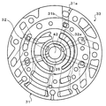
- FIG. 20 It is a schematic block diagram of the power transmission device 20 which concerns on the Example of this invention. It is a fragmentary sectional view showing the inside of transaxle case 21b of power transmission device 20 of an example. 3 is a schematic configuration diagram showing a pump assembly 33 including a pump body 31 and a pump cover 32. FIG. It is a schematic block diagram of 20 A of power transmission devices which concern on a modification.
- FIG. 1 is a schematic configuration diagram showing a power transmission device (transmission) according to an embodiment of the present invention.
- a power transmission device 20 shown in the figure is applied to a front-wheel drive vehicle and transmits power from an engine (not shown) mounted on the front of the vehicle to left and right front wheels, and is integrally coupled to a converter housing 21a,
- CVT continuously variable transmission unit
- the torque converter 22 is configured as a fluid torque converter with a lock-up clutch, and is accommodated in the converter housing 21a. As shown in FIG. 1, the torque converter 22 is disposed inside a pump impeller 23 connected to an engine crankshaft (not shown), a turbine runner 24 fixed to an input shaft 41 of the CVT 40, the pump impeller 23, and the turbine runner 24. It includes a stator 25 arranged, a one-way clutch CO that restricts the rotational direction of the stator 25 to one direction, a lock-up clutch 28 having a damper mechanism 27, and the like.
- the torque converter 22 operates as a torque amplifier when the rotational speed difference between the pump impeller 23 and the turbine runner 24 is large, and operates as a fluid coupling when the rotational speed difference between the two becomes small.
- the pump impeller 23 and the turbine runner 24 are locked by the lock-up clutch 28 so that the power from the engine is mechanically and directly transmitted to the input shaft 41. become.
- the fluctuation of the torque transmitted to the input shaft 41 is absorbed by the damper mechanism 27.
- the oil pump 30 is configured as a so-called gear pump including a pump assembly 33 including a pump body 31 and a pump cover 32 disposed between the torque converter 22 and the forward / reverse switching unit 35 and an external gear 34. .
- the pump body 31 and the pump cover 32 are fixed to the converter housing 21a and the transaxle case 21b.
- the external gear 34 is connected to the pump impeller 23 via a hub, and forms a crescent with internal teeth (not shown) formed in the pump body 31.
- the forward / reverse switching unit 35 is housed in the transaxle case 21b, and includes a double pinion planetary gear mechanism 36, and a hydraulic brake B1 and a clutch C1 that operate using working fluid from the oil pump 30.
- the planetary gear mechanism 36 includes a sun gear fixed to the input shaft 41 of the CVT 40, a ring gear, a pinion gear meshing with the sun gear, and a carrier supporting the pinion gear meshing with the ring gear and coupled to the primary shaft 42 of the CVT 40.
- the brake B1 can fix the ring gear of the planetary gear mechanism 36 with respect to the transaxle case 21b and can be freely rotated.
- the clutch C1 uses the carrier of the planetary gear mechanism 36 as an input shaft 41 (sun gear).
- the CVT 40 is housed inside the transaxle case 21b and the rear cover 21c, and has a primary shaft 42 as a drive side rotating shaft extending coaxially with the input shaft 41, a primary pulley 43 provided for the primary shaft 42, A secondary shaft (output shaft) 44 as a driven side rotating shaft extending in parallel with the primary shaft 42, a secondary pulley 45 provided for the secondary shaft 44, and the primary pulley 43 and the secondary pulley 45 are wound around Belt 46.
- the primary pulley 43 includes a fixed sheave 43a formed integrally with the primary shaft 42, and a movable sheave 43b supported on the primary shaft 42 through a ball spline or the like so as to be slidable in the axial direction.
- a hydraulic cylinder (hydraulic actuator) 47 for changing the groove width of the primary pulley 43 is formed behind the movable sheave 43 b of the primary pulley 43.
- the secondary pulley 45 includes a fixed sheave 45a formed integrally with the secondary shaft 44, and a movable sheave 45b supported by the secondary shaft 44 so as to be slidable in the axial direction via a ball spline, a return spring, or the like. Is done.
- a hydraulic cylinder (hydraulic actuator) 48 for changing the groove width of the secondary pulley 45 is formed behind the movable sheave 45 b of the secondary pulley 45.
- a cancel plate 49 that defines a cancel chamber is provided behind the hydraulic cylinder 48 with respect to the secondary pulley 45.
- the centrifugal oil pressure acting on the hydraulic cylinder 48 can be canceled by the centrifugal oil pressure acting on the working fluid in the cancel chamber.
- a hydraulic circuit (valve body) 90 in which the working fluid pressurized by the oil pump 30 includes a plurality of control valves. (Refer to FIG. 2) The pressure is regulated and supplied, thereby changing the groove widths of the primary pulley 43 and the secondary pulley 45 to change the power input from the input shaft 41 to the primary shaft 42 steplessly. Thus, it is possible to output to the secondary shaft 44.
- the wheel base which is the distance between the front and rear axles, can be easily extended, so that the indoor space, the cargo space, and the like can be enlarged.
- the right side in the figure is the vehicle front (F) side and the left side in the figure is the vehicle rear (R) side.
- the oil pump 30 is driven by the power from the engine during its travel, so the operation sucked from the oil pan 80 by the oil pump 30.
- the fluid (ATF) is supplied as a lubrication medium to the torque converter 22, the forward / reverse switching unit 35, the CVT 40, etc. that require lubrication (the object to be lubricated).
- the oil pump 30 cannot be driven because the engine is stopped when the vehicle equipped with the power transmission device 20 due to a failure or the like is towed by another vehicle with four wheels installed.
- the working fluid as the lubricating medium cannot be supplied to the object to be lubricated using the oil pump 30.
- the power transmission device 20 of the embodiment has a structure in which the structure of a general power transmission device for a front wheel drive vehicle is mirror-inverted so as to correspond to the long wheel base of the vehicle as described above.
- the lowermost differential ring gear 65 removes the working fluid accumulated in the inner bottom portion of the case 21, as indicated by a two-dot chain line arrow in FIG. Instead of being along the inner wall surface of the converter housing 21a, it is scraped up toward the center inside the case.
- the working fluid pumped up by the lowermost diffring gear 65 is not carried by the gear mechanism 60, and in the embodiment, it is positioned on the vehicle rear side of the diffring gear 65 and below the CVT 40.
- the oil flows into the oil pan 80 attached to the case 21, and when the vehicle is towed, the working fluid as the lubricating medium cannot be sufficiently supplied to the forward / reverse switching unit 35 to be lubricated, There is a possibility that the working fluid in the inner bottom portion of the case 21 to be scraped up by the ring gear 65 is insufficient.
- the upper end portion of the partition wall 21 w operates as a meshing portion between the drive pinion gear 64 and the diff ring gear 65 as an intermediate gear between the diff ring gear 65 and the counter drive gear 61 as shown in FIG. Positioned to direct fluid.
- the width of the partition wall 21w that is, the length of the partition wall 21w in the direction parallel to the differential shafts 70a and 70b, the counter shaft 62, etc., may be a length corresponding to the thickness of the differential ring gear 65.
- the width of the partition wall 21w is set to the internal width of the case 21 (in the embodiment, the length of the counter shaft 62 is approximately the same) so that a necessary and sufficient working fluid can be stored in the bottom of the case around the differential ring gear 65. ).
- the partition wall 21w defines the accommodating part of the diff ring gear 65 and the differential mechanism 66 with the converter housing 21a and the inner wall surface of the transaxle case 21b.
- the accommodating portion such as the diff ring gear 65 is formed in a side wall portion facing the engine side surface of the diff ring gear 65 of the converter housing 21a and extends in parallel with the diff shafts 70a, 70b, etc., that is, the shaft of the diff ring gear 65.
- the oil pan 80 communicates with the inside through a communication path including a flow path extending along the direction.
- a rib (not shown) formed on the inner surface of the side wall portion of the transaxle case 21b and the partition wall 21w are made continuous to ensure the strength. And preferred.
- the working fluid scraped up by the diff ring gear 65 can be better directed to the meshing portion between the def ring gear 65 and the drive pinion gear 64 as an intermediate gear. It becomes possible.
- the rotation directions of the lowermost diffring gear 65 and the uppermost counter drive gear 61 coincide. Accordingly, if no measures are taken, the working fluid is lifted up by the diff ring gear 65 and guided by the partition wall 21w to be guided to the meshing portion between the drive pinion gear 64 and the diff ring gear 65 and carried upward by the drive pinion gear 64. Is guided to the meshing portion between the counter driven gear 63 and the counter drive gear 61 as an intermediate gear by the rotation of the counter drive gear 61, and the working fluid falls to the oil pan 80 without being guided further upward. There is also a fear.
- the power transmission device 20 of the embodiment surrounds a part of the outer periphery of the uppermost counter drive gear 61 with respect to the transaxle case 21b and is scraped up by the diff ring gear 65 and the gear.
- a guide wall 21g is provided for guiding the working fluid carried by the mechanism 60, that is, the drive pinion gear 64 and the diff ring gear 65, to the hole 31a of the pump body 31 which is the inlet of the lubricating flow path 32a.
- the guide wall 21g extends from the inner surface of the side wall portion of the transaxle case 21b so as to surround the upper half of the outer periphery of the uppermost counter drive gear 61.
- the power transmission device 20 is positioned at the lowermost side in the case 21 among the gears included in the gear mechanism 60 when the vehicle is mounted, and the case 21 is rotated when the differential shafts 70a and 70b are rotated forward. It has a diff ring gear 65 that scoops the working fluid in the inner bottom toward the center inside the case without being along the inner wall surface of the case 21, and mirrors the structure of a general power transmission device for a front wheel drive vehicle Has a structure. Therefore, in a vehicle equipped with the power transmission device 20, the primary shaft 42 of the CVT 40 is positioned on the vehicle rear side with respect to the diff ring gear 65 and the differential mechanism 66 when mounted on the vehicle, so that the wheel base can be easily extended. it can.
- the power transmission device 20 includes a counter that is positioned on the uppermost side in the case 21 among the gears included in the gear mechanism 60 when mounted on the vehicle and that rotates in the same direction as the diff ring gear 65 when the differential shafts 70a and 70b are rotated forward.
- a guide wall 21g that surrounds a part of the outer periphery of the drive gear 61 and guides the working fluid that is scraped up by the differential gear 65 and carried by the gear mechanism 60 to the hole 31a that is the inlet of the lubrication flow path 32a of the pump assembly 33. Is provided.
- the guide wall 21g surrounding a part of the outer periphery of the uppermost counter drive gear 61 can prevent the progress of the working fluid from being hindered by the rotation of the counter drive gear 61.
- a large amount of working fluid can be guided to the lubrication flow path 32a and supplied to the forward / reverse switching unit 35 as a lubrication target. Therefore, in the front-wheel drive vehicle equipped with the power transmission device 20 of the embodiment, the wheel base can be easily extended, and the working fluid as the lubricating medium cannot be supplied to the forward / reverse switching unit 35 using the oil pump 30. Even during towing, the working fluid can be supplied to the forward / reverse switching unit 35 sufficiently and sufficiently.
- the primary shaft 42 of the CVT 40 is in an overdrive state with respect to the differential shafts 70a and 70b as the axles when being pulled, and the primary shaft 42 rotates at a relatively high speed.
- the forward / reverse switching unit 35 can be favorably lubricated by the working fluid from the lubrication flow path 32a, it becomes possible to satisfactorily perform towing of the vehicle on which the power transmission device 20 is mounted.
- the guide wall 21g of the embodiment surrounds the upper half of the outer periphery of the uppermost counter drive gear 61 and has a flow path 21p that faces the hole 31a that is the inlet of the lubricating flow path 32a together with the upper inner wall surface of the case 21.
- the working fluid that has entered the flow path 21p defined by the guide wall 21g and the upper inner wall surface of the case 21 is not affected by the rotation of the counter drive gear 61. Therefore, the working fluid that has entered the flow path 21p can be guided well to the hole 31a that is the inlet of the lubrication flow path 32a.
- the working fluid conveyed by the differential ring gear 65 and the drive pinion gear 64 as an intermediate gear is received, and the working fluid to the meshing portion of the counter drive gear 61 and the counter driven gear 63 as the intermediate gear is received. If the end of the guide wall 21g opposite to the hole 31a is positioned so as to suppress the fall of the guide wall 21g, the working fluid carried up by the diff ring gear 65 and the drive pinion gear 64 is scraped up by the diff ring gear 65. It is possible to more reliably lead to the flow path 21p defined by the guide wall 21g and the upper inner wall surface of the case 21.
- the power transmission device 20 has a partition wall 21w that extends upward from the inner bottom of the case 21 and surrounds a part of the outer periphery of the diff ring gear 65 at the center inside the case. It is possible to satisfactorily guide the scraped working fluid to the meshing portion between the differential ring gear 65 and the drive pinion gear 64 as an intermediate gear.
- the guide wall 21g of the power transmission device 20 of the above-described embodiment forms a flow path 21p that surrounds the upper half of the outer periphery of the uppermost counter drive gear 61 and faces the hole 31a together with the upper inner wall surface of the transaxle case 21b.
- a guide wall a guide wall provided for the power transmission device 20A shown in FIG. 4 may be adopted.
- the guide wall 21g 'provided in the power transmission device 20A in FIG. 4 is located near the meshing portion between the uppermost counter drive gear 61 and the counter driven gear 63 as an intermediate gear, and near the hole 31a that is the inlet of the lubricating flow path 32a.
- the flow passage 21p that surrounds the lower outer periphery of the counter drive gear 61 and faces the hole 31a together with the outer periphery of the counter drive gear 61 and the upper inner wall surface of the case 21 is defined.
- the working fluid scraped up by the diff ring gear 65 is brought into engagement with the drive pinion gear 64 and the diff ring gear 65 by the partition wall 21w.
- a driving pinion gear 64 as an intermediate gear guides the working fluid from a meshing portion of the counter drive gear 61 and the counter driven gear 63 as an intermediate gear to a flow path 21p defined by the guide wall 21g '.
- the working fluid guided to the wall 21g '(flow path 21p) is utilized to rotate to the hole 31a that is the inlet of the lubrication flow path 32a by using the rotation of the counter drive gear 61 (taken up by the counter drive gear 61). It can lead well.
- the guide wall 21g ′ may also be divided into a plurality of parts such as a part surrounding the counter drive gear 61 and a part forming an oil sump.
- the present invention can be used in the manufacturing industry of power transmission devices for vehicles.
Landscapes
- Engineering & Computer Science (AREA)
- General Engineering & Computer Science (AREA)
- Mechanical Engineering (AREA)
- General Details Of Gearings (AREA)
Abstract
Description
車両に搭載されると共に動力発生源からの動力をケース内に収容されたギヤ列を介して車軸に伝達する車両用動力伝達装置において、
前記動力発生源により駆動されて潤滑対象に対して潤滑媒体を供給可能な潤滑用ポンプと、
前記潤滑媒体を貯留する潤滑媒体貯留部と、
車載時に前記ギヤ列に含まれるギヤの中で前記ケース内の最下側に位置すると共に、前記車軸の正転時に前記ケースの内底部の潤滑媒体を前記ケースの内壁面に沿わせずに該ケース内部の中央に向けて掻き上げる最下側ギヤと、
車載時に前記ギヤ列に含まれるギヤの中で前記ケース内の最上側に位置し、前記車軸の正転時に前記最下側ギヤと同方向に回転する最上側ギヤと、
前記最下側ギヤにより掻き上げられると共に前記ギヤ列により運ばれる潤滑媒体を所定の潤滑対象に導くための潤滑流路と、
前記最上側ギヤの外周の一部を囲み、前記最下側ギヤにより掻き上げられると共に前記ギヤ列により運ばれる潤滑媒体を前記潤滑流路の入口へと案内するガイド部と、
を備えるものである。
Claims (7)
- 車両に搭載されると共に動力発生源からの動力をケース内に収容されたギヤ列を介して車軸に伝達する車両用動力伝達装置において、
前記動力発生源により駆動されて潤滑対象に対して潤滑媒体を供給可能な潤滑用ポンプと、
前記潤滑媒体を貯留する潤滑媒体貯留部と、
車載時に前記ギヤ列に含まれるギヤの中で前記ケース内の最下側に位置すると共に、前記車軸の正転時に前記ケースの内底部の潤滑媒体を前記ケースの内壁面に沿わせずに該ケース内部の中央に向けて掻き上げる最下側ギヤと、
車載時に前記ギヤ列に含まれるギヤの中で前記ケース内の最上側に位置し、前記車軸の正転時に前記最下側ギヤと同方向に回転する最上側ギヤと、
前記最下側ギヤにより掻き上げられると共に前記ギヤ列により運ばれる潤滑媒体を所定の潤滑対象に導くための潤滑流路と、
前記最上側ギヤの外周の一部を囲み、前記最下側ギヤにより掻き上げられると共に前記ギヤ列により運ばれる潤滑媒体を前記潤滑流路の入口へと案内するガイド部と、
を備える車両用動力伝達装置。 - 請求項1に記載の車両用動力伝達装置において、
前記ガイド部は、前記最上側ギヤの上側外周を囲んで前記ケースの内壁面と共に前記潤滑流路の入口に臨む流路を画成する車両用動力伝達装置。 - 請求項2に記載の車両用動力伝達装置において、
前記ギヤ列は、前記最下側ギヤと前記最上側ギヤとの間に設けられた中間ギヤを含み、
前記ガイド部の前記潤滑流路の入口側と反対側の端部は、前記最下側ギヤと前記中間ギヤとにより運ばれる潤滑媒体を受容すると共に前記最上側ギヤと前記中間ギヤとの噛合部への潤滑媒体の落下を抑制するように位置決めされている車両用動力伝達装置。 - 請求項1に記載の車両用動力伝達装置において、
前記ギヤ列は、前記最下側ギヤと前記最上側ギヤとの間に設けられた中間ギヤを含み、
前記ガイド部は、前記最上側ギヤと前記中間ギヤとの噛合部近傍から前記潤滑流路の入口近傍まで前記最上側ギヤの下側外周を囲む車両用動力伝達装置。 - 請求項3または4に記載の車両用動力伝達装置において、
前記ケースの前記内底部から上方に延出して前記ケース内部の中央側で前記最下側ギヤの外周の一部を囲む仕切壁を更に備える車両用動力伝達装置。 - 請求項1から5の何れか一項に記載の車両用動力伝達装置において、
前記ケース内に収容されると共に前記動力発生源からの動力を無段階に変速して前記ギヤ列に伝達可能な無段変速ユニットを更に備え、
前記車両は前輪駆動車両であり、前記最下側ギヤは差動機構に連結されるデフリングギヤであり、前記無段変速ユニットのプライマリシャフトは車載時に前記最下側ギヤよりも車両後方側に位置する車両用動力伝達装置。 - 請求項6に記載の車両用動力伝達装置において、
前記無段変速ユニットの前記プライマリシャフトに接続されると共に、前記潤滑流路から潤滑媒体の供給を受ける潤滑対象としての前後進切換ユニットを更に備える車両用動力伝達装置。
Priority Applications (2)
| Application Number | Priority Date | Filing Date | Title |
|---|---|---|---|
| CN2008800204247A CN101707902B (zh) | 2007-12-27 | 2008-12-19 | 车辆用动力传递装置 |
| DE112008001606T DE112008001606T5 (de) | 2007-12-27 | 2008-12-19 | Fahrzeugkraftübertragungsvorrichtung |
Applications Claiming Priority (2)
| Application Number | Priority Date | Filing Date | Title |
|---|---|---|---|
| JP2007336067A JP4898653B2 (ja) | 2007-12-27 | 2007-12-27 | 車両用動力伝達装置 |
| JP2007-336067 | 2007-12-27 |
Publications (1)
| Publication Number | Publication Date |
|---|---|
| WO2009084487A1 true WO2009084487A1 (ja) | 2009-07-09 |
Family
ID=40796513
Family Applications (1)
| Application Number | Title | Priority Date | Filing Date |
|---|---|---|---|
| PCT/JP2008/073247 Ceased WO2009084487A1 (ja) | 2007-12-27 | 2008-12-19 | 車両用動力伝達装置 |
Country Status (5)
| Country | Link |
|---|---|
| US (1) | US8261883B2 (ja) |
| JP (1) | JP4898653B2 (ja) |
| CN (1) | CN101707902B (ja) |
| DE (1) | DE112008001606T5 (ja) |
| WO (1) | WO2009084487A1 (ja) |
Families Citing this family (32)
| Publication number | Priority date | Publication date | Assignee | Title |
|---|---|---|---|---|
| JP4744581B2 (ja) * | 2008-10-07 | 2011-08-10 | アイシン・エィ・ダブリュ株式会社 | 車両用動力伝達装置 |
| JP4770947B2 (ja) * | 2009-03-02 | 2011-09-14 | トヨタ自動車株式会社 | 車両の動力伝達装置 |
| US8371978B2 (en) * | 2010-03-31 | 2013-02-12 | Aisin Aw Co., Ltd. | Vehicle transmission |
| JP5333320B2 (ja) * | 2010-03-31 | 2013-11-06 | アイシン・エィ・ダブリュ株式会社 | 動力伝達装置 |
| JP5760215B2 (ja) * | 2011-01-24 | 2015-08-05 | 株式会社 神崎高級工機製作所 | 作業車両の車軸駆動装置 |
| JP5809829B2 (ja) * | 2011-03-31 | 2015-11-11 | 本田技研工業株式会社 | エンジンの潤滑構造 |
| JP5408218B2 (ja) * | 2011-09-29 | 2014-02-05 | アイシン・エィ・ダブリュ株式会社 | 動力伝達装置 |
| JP5790630B2 (ja) * | 2012-12-05 | 2015-10-07 | トヨタ自動車株式会社 | 潤滑油供給構造 |
| US9791001B2 (en) * | 2012-12-27 | 2017-10-17 | Toyota Jidosha Kabushiki Kaisha | Power transmitting apparatus for vehicle |
| CN103895795A (zh) * | 2014-03-25 | 2014-07-02 | 重庆隆鑫发动机有限公司 | 摩托车驱动悬置连接构造及摩托车 |
| JP6179899B2 (ja) * | 2014-09-24 | 2017-08-16 | 本田技研工業株式会社 | 車両用パワーユニット |
| JP6129139B2 (ja) * | 2014-10-30 | 2017-05-17 | アイシン精機株式会社 | 減速機の潤滑構造 |
| JP6076314B2 (ja) * | 2014-10-30 | 2017-02-08 | アイシン精機株式会社 | 減速機の潤滑構造 |
| JP6129150B2 (ja) * | 2014-12-24 | 2017-05-17 | アイシン精機株式会社 | 車両駆動装置の潤滑構造 |
| JP6086897B2 (ja) * | 2014-12-24 | 2017-03-01 | アイシン精機株式会社 | 車両駆動装置の潤滑構造 |
| KR101547688B1 (ko) | 2015-03-13 | 2015-08-27 | 신정개발특장차 주식회사 | 중간변속기용 하우징 |
| US10208848B2 (en) * | 2015-07-29 | 2019-02-19 | GM Global Technology Operations LLC | Gear baffle |
| US9772027B2 (en) * | 2015-10-08 | 2017-09-26 | GM Global Technology Operations LLC | Variable baffle that reduces oil at the gear mesh |
| US20180149260A1 (en) * | 2016-11-30 | 2018-05-31 | GM Global Technology Operations LLC | Apparatus for active thermal management of transmission lubricant |
| JP6551389B2 (ja) * | 2016-12-27 | 2019-07-31 | トヨタ自動車株式会社 | ハイブリッド車両の潤滑構造 |
| US10309519B2 (en) * | 2017-02-17 | 2019-06-04 | Ford Global Technologies, Llc | Baffle for automotive transmission |
| US10859152B2 (en) * | 2017-11-13 | 2020-12-08 | Zhejiang Xin Precision Mach Co., Ltd. | Pure electric vehicle transmission with novel lubrication structure |
| WO2019229490A1 (en) | 2018-05-30 | 2019-12-05 | Carrier Corporation | Energy management systems (ems) for transportation refrigeration units (tru) |
| RU2719740C1 (ru) * | 2019-09-11 | 2020-04-22 | Федеральное государственное бюджетное образовательное учреждение высшего образования "Рыбинский государственный авиационный технический университет имени П.А. Соловьева" | Планетарный зубчатый редуктор с двухвенцовыми сателлитами |
| KR102852654B1 (ko) * | 2020-07-23 | 2025-08-29 | 현대모비스 주식회사 | 인휠 구동 장치 |
| US11662013B2 (en) * | 2020-09-24 | 2023-05-30 | GM Global Technology Operations LLC | Stalactite passive lubrication system |
| DE102021206607B3 (de) * | 2021-06-25 | 2022-10-20 | Vitesco Technologies Germany Gmbh | Ölverteiler, Achsantrieb und Kraftfahrzeug |
| JP7445697B2 (ja) * | 2022-03-30 | 2024-03-07 | 本田技研工業株式会社 | 車両用動力伝達装置の潤滑構造 |
| CN116928325A (zh) * | 2022-03-30 | 2023-10-24 | 比亚迪股份有限公司 | 车辆的变速器、动力总成和车辆 |
| CN116928326A (zh) * | 2022-04-01 | 2023-10-24 | 罗伯特·博世有限公司 | 变速箱 |
| US12215774B2 (en) * | 2022-11-28 | 2025-02-04 | Dana Italia S.R.L. | Systems and methods for gearbox fluid reservoir |
| CN119103330A (zh) * | 2023-06-09 | 2024-12-10 | 法雷奥新能源汽车德国有限责任公司 | 一种传动系统和车辆 |
Citations (6)
| Publication number | Priority date | Publication date | Assignee | Title |
|---|---|---|---|---|
| JPS53106571U (ja) * | 1977-01-31 | 1978-08-26 | ||
| JPS60229824A (ja) * | 1984-02-27 | 1985-11-15 | ナシヨナル・リサ−チ・デイベロツプメント・コ−ポレイシヨン | 自動車の駆動システム |
| JPH0514728U (ja) * | 1991-08-08 | 1993-02-26 | 愛知機械工業株式会社 | 動力伝達装置における軸受部の給油構造 |
| JPH1026217A (ja) * | 1996-07-09 | 1998-01-27 | Daihatsu Motor Co Ltd | 自動車用動力伝達系の潤滑装置 |
| JP2004183714A (ja) * | 2002-11-29 | 2004-07-02 | Aisin Aw Co Ltd | 車輌用変速機の潤滑装置 |
| JP2006083934A (ja) * | 2004-09-15 | 2006-03-30 | Kawasaki Heavy Ind Ltd | 車輌用トランスミッションのオイル供給構造 |
Family Cites Families (42)
| Publication number | Priority date | Publication date | Assignee | Title |
|---|---|---|---|---|
| US3625310A (en) * | 1970-01-20 | 1971-12-07 | Dresser Ind | Gearbox lubrication |
| US3672586A (en) * | 1970-10-28 | 1972-06-27 | Leesona Corp | Winding apparatus |
| JPS53106571A (en) * | 1977-02-28 | 1978-09-16 | Nec Corp | Testing method of galllium aresenide semi-insulating substrate |
| US4227427A (en) * | 1977-09-08 | 1980-10-14 | Dana Corporation | Drive unit assembly |
| JPS5455261A (en) * | 1977-10-12 | 1979-05-02 | Toyota Motor Corp | Lubricant induction unit for gear transmission |
| US4242923A (en) * | 1977-11-02 | 1981-01-06 | Toyota Jidosha Kogyo Kabushiki Kaisha | Lubrication in power transmission unit |
| JPS6113801Y2 (ja) * | 1980-08-20 | 1986-04-28 | ||
| US4414861A (en) * | 1982-02-17 | 1983-11-15 | The Falk Corporation | Gear drive cooling |
| JPH0656193B2 (ja) * | 1984-07-13 | 1994-07-27 | ヤマハ発動機株式会社 | 車両用副変速機付内燃機関 |
| JPH063255B2 (ja) * | 1987-03-04 | 1994-01-12 | トヨタ自動車株式会社 | 自動変速機のトランスアクスルケ−ス |
| EP0289024A3 (en) * | 1987-04-30 | 1990-07-11 | Honda Giken Kogyo Kabushiki Kaisha | Belt-and-pulley type continuously variable transmission |
| US5404964A (en) * | 1991-08-05 | 1995-04-11 | Carrier Corporation | System for reducing oil migration from a transmission |
| DE4214827A1 (de) * | 1992-05-10 | 1993-11-11 | Eric Van Damme | Vorrichtung zum dosierten Zuführen von flüssigen oder viskosen Substanzen an eine Verbrauchsstelle |
| US5472383A (en) * | 1993-12-27 | 1995-12-05 | United Technologies Corporation | Lubrication system for a planetary gear train |
| US5601155A (en) * | 1995-07-05 | 1997-02-11 | Delaware Capital Formation, Inc. | Journal bearing using disk for transporting lubricant |
| DE69626762D1 (de) * | 1995-12-15 | 2003-04-24 | Aisin Aw Co | Stufenloses Getriebe |
| DE19602041C2 (de) * | 1996-01-20 | 1998-10-15 | Ford Global Tech Inc | Schaltgabel für ein Wechselgetriebe |
| JPH1038058A (ja) * | 1996-07-23 | 1998-02-13 | Jatco Corp | 自動変速機の油潤滑構造 |
| EP0838613B1 (en) * | 1996-10-25 | 2002-08-14 | Aisin Aw Co., Ltd. | Infinitely variable transmission |
| JP3259826B2 (ja) * | 1997-01-24 | 2002-02-25 | 愛知機械工業株式会社 | ベルト式無段変速機のプーリ油路構造 |
| JP3910251B2 (ja) | 1997-03-17 | 2007-04-25 | 富士重工業株式会社 | 車両用変速装置の潤滑構造 |
| JP3646498B2 (ja) * | 1997-12-26 | 2005-05-11 | スズキ株式会社 | トランスミッションの潤滑装置 |
| US6044931A (en) * | 1998-09-15 | 2000-04-04 | Chrysler Corporation | Lubrication system for an automatic transmission having dual input shafts |
| US6135241A (en) * | 1999-02-24 | 2000-10-24 | Dana Corporation | Axle housing with a deflector |
| DE19908840A1 (de) * | 1999-03-01 | 2000-09-07 | Zahnradfabrik Friedrichshafen | Stufenautomatgetriebe |
| US6161650A (en) * | 1999-03-22 | 2000-12-19 | Cedarapids Inc. | Lubricating system for a vibratory apparatus |
| JP4179715B2 (ja) * | 1999-09-03 | 2008-11-12 | 本田技研工業株式会社 | 内燃機関用潤滑装置 |
| US6634459B1 (en) * | 2001-08-10 | 2003-10-21 | Caterpillar Inc | Accessory drive and particle trap |
| JP4007887B2 (ja) * | 2002-09-18 | 2007-11-14 | 本田技研工業株式会社 | 内燃機関の潤滑装置 |
| JP2004340096A (ja) * | 2003-05-19 | 2004-12-02 | Fuji Heavy Ind Ltd | クランクケースのブリーザ装置 |
| JP4645877B2 (ja) | 2003-09-08 | 2011-03-09 | アイシン・エィ・ダブリュ株式会社 | 車両用駆動装置の潤滑装置 |
| KR100692124B1 (ko) * | 2003-11-04 | 2007-03-12 | 현대자동차주식회사 | 자동 변속기 오일 누유 방지장치 |
| DE10359109A1 (de) * | 2003-12-17 | 2005-07-21 | Deere & Company, Moline | Getriebeanordnung für ein Fahrzeug |
| JP4639591B2 (ja) | 2004-01-14 | 2011-02-23 | トヨタ自動車株式会社 | 車軸駆動装置 |
| JP4074278B2 (ja) * | 2004-09-09 | 2008-04-09 | ジヤトコ株式会社 | バッフルプレート排油構造 |
| US20070144283A1 (en) * | 2005-11-30 | 2007-06-28 | Toshiyuki Hasegawa | Power Transmission Apparatus |
| JP2007255369A (ja) * | 2006-03-24 | 2007-10-04 | Jatco Ltd | 変速機のオイルポンプ構造 |
| JP4846451B2 (ja) * | 2006-05-26 | 2011-12-28 | 本田技研工業株式会社 | パワーユニット |
| JP2007314065A (ja) * | 2006-05-26 | 2007-12-06 | Honda Motor Co Ltd | 車両の動力伝達装置 |
| JP2008014406A (ja) * | 2006-07-06 | 2008-01-24 | Jatco Ltd | 自動変速機 |
| US7712581B2 (en) * | 2006-09-26 | 2010-05-11 | Gm Global Technology Operations, Inc | Transmission having a sealing baffle |
| JP5290029B2 (ja) * | 2009-03-31 | 2013-09-18 | 本田技研工業株式会社 | 内燃機関 |
-
2007
- 2007-12-27 JP JP2007336067A patent/JP4898653B2/ja not_active Expired - Fee Related
-
2008
- 2008-12-19 CN CN2008800204247A patent/CN101707902B/zh not_active Expired - Fee Related
- 2008-12-19 WO PCT/JP2008/073247 patent/WO2009084487A1/ja not_active Ceased
- 2008-12-19 DE DE112008001606T patent/DE112008001606T5/de not_active Withdrawn
- 2008-12-23 US US12/318,229 patent/US8261883B2/en not_active Expired - Fee Related
Patent Citations (6)
| Publication number | Priority date | Publication date | Assignee | Title |
|---|---|---|---|---|
| JPS53106571U (ja) * | 1977-01-31 | 1978-08-26 | ||
| JPS60229824A (ja) * | 1984-02-27 | 1985-11-15 | ナシヨナル・リサ−チ・デイベロツプメント・コ−ポレイシヨン | 自動車の駆動システム |
| JPH0514728U (ja) * | 1991-08-08 | 1993-02-26 | 愛知機械工業株式会社 | 動力伝達装置における軸受部の給油構造 |
| JPH1026217A (ja) * | 1996-07-09 | 1998-01-27 | Daihatsu Motor Co Ltd | 自動車用動力伝達系の潤滑装置 |
| JP2004183714A (ja) * | 2002-11-29 | 2004-07-02 | Aisin Aw Co Ltd | 車輌用変速機の潤滑装置 |
| JP2006083934A (ja) * | 2004-09-15 | 2006-03-30 | Kawasaki Heavy Ind Ltd | 車輌用トランスミッションのオイル供給構造 |
Also Published As
| Publication number | Publication date |
|---|---|
| US20090165587A1 (en) | 2009-07-02 |
| JP4898653B2 (ja) | 2012-03-21 |
| US8261883B2 (en) | 2012-09-11 |
| CN101707902B (zh) | 2013-09-25 |
| JP2009156364A (ja) | 2009-07-16 |
| CN101707902A (zh) | 2010-05-12 |
| DE112008001606T5 (de) | 2010-09-30 |
Similar Documents
| Publication | Publication Date | Title |
|---|---|---|
| JP4898653B2 (ja) | 車両用動力伝達装置 | |
| JP4898654B2 (ja) | 車両用動力伝達装置 | |
| JP4744581B2 (ja) | 車両用動力伝達装置 | |
| US7743888B2 (en) | Transmission and transfer case having integrated lubrication systems | |
| US8495928B2 (en) | Vehicle transmission | |
| JP2006275164A (ja) | 車両用デファレンシャル装置 | |
| WO2011122192A1 (ja) | 動力伝達装置 | |
| WO2016114007A1 (ja) | 変速機 | |
| JP4020240B2 (ja) | 無段変速機における潤滑構造 | |
| JPH1163176A (ja) | 遊星歯車装置の潤滑油供給構造 | |
| JP2010025287A (ja) | 車両のベルト式無段変速装置 | |
| JP3882431B2 (ja) | 車輌用自動変速機の潤滑装置 | |
| JP4302704B2 (ja) | ハイブリッド車両駆動装置 | |
| JP3748680B2 (ja) | 無段変速機の潤滑構造 | |
| JP2001165287A (ja) | 車輌用自動変速機の潤滑装置 | |
| JP4329457B2 (ja) | ベルト式無段変速機 | |
| JP3952947B2 (ja) | 車輌用変速機の潤滑装置 | |
| JP6654542B2 (ja) | 車両用自動変速機 | |
| JP3903605B2 (ja) | トロイダル式無段変速機 | |
| JP3163252B2 (ja) | ピニオンの潤滑構造 | |
| JP7240851B2 (ja) | 差動機構の潤滑構造 | |
| JP2009250280A (ja) | 無段変速機 | |
| JPH11278079A (ja) | 車両用駆動装置 | |
| JP2006183743A (ja) | 車両の動力伝達装置 | |
| JPH0811560A (ja) | 車両用動力伝達装置 |
Legal Events
| Date | Code | Title | Description |
|---|---|---|---|
| WWE | Wipo information: entry into national phase |
Ref document number: 200880020424.7 Country of ref document: CN |
|
| 121 | Ep: the epo has been informed by wipo that ep was designated in this application |
Ref document number: 08868951 Country of ref document: EP Kind code of ref document: A1 |
|
| WWE | Wipo information: entry into national phase |
Ref document number: 1120080016062 Country of ref document: DE |
|
| RET | De translation (de og part 6b) |
Ref document number: 112008001606 Country of ref document: DE Date of ref document: 20100930 Kind code of ref document: P |
|
| 122 | Ep: pct application non-entry in european phase |
Ref document number: 08868951 Country of ref document: EP Kind code of ref document: A1 |