WO2005093864A1 - 熱電変換素子及び熱電変換モジュール - Google Patents
熱電変換素子及び熱電変換モジュール Download PDFInfo
- Publication number
- WO2005093864A1 WO2005093864A1 PCT/JP2005/005133 JP2005005133W WO2005093864A1 WO 2005093864 A1 WO2005093864 A1 WO 2005093864A1 JP 2005005133 W JP2005005133 W JP 2005005133W WO 2005093864 A1 WO2005093864 A1 WO 2005093864A1
- Authority
- WO
- WIPO (PCT)
- Prior art keywords
- thermoelectric conversion
- thin film
- type thermoelectric
- conversion material
- group
- Prior art date
Links
Classifications
-
- C—CHEMISTRY; METALLURGY
- C04—CEMENTS; CONCRETE; ARTIFICIAL STONE; CERAMICS; REFRACTORIES
- C04B—LIME, MAGNESIA; SLAG; CEMENTS; COMPOSITIONS THEREOF, e.g. MORTARS, CONCRETE OR LIKE BUILDING MATERIALS; ARTIFICIAL STONE; CERAMICS; REFRACTORIES; TREATMENT OF NATURAL STONE
- C04B35/00—Shaped ceramic products characterised by their composition; Ceramics compositions; Processing powders of inorganic compounds preparatory to the manufacturing of ceramic products
- C04B35/01—Shaped ceramic products characterised by their composition; Ceramics compositions; Processing powders of inorganic compounds preparatory to the manufacturing of ceramic products based on oxide ceramics
-
- C—CHEMISTRY; METALLURGY
- C03—GLASS; MINERAL OR SLAG WOOL
- C03C—CHEMICAL COMPOSITION OF GLASSES, GLAZES OR VITREOUS ENAMELS; SURFACE TREATMENT OF GLASS; SURFACE TREATMENT OF FIBRES OR FILAMENTS MADE FROM GLASS, MINERALS OR SLAGS; JOINING GLASS TO GLASS OR OTHER MATERIALS
- C03C17/00—Surface treatment of glass, not in the form of fibres or filaments, by coating
- C03C17/22—Surface treatment of glass, not in the form of fibres or filaments, by coating with other inorganic material
- C03C17/23—Oxides
-
- C—CHEMISTRY; METALLURGY
- C04—CEMENTS; CONCRETE; ARTIFICIAL STONE; CERAMICS; REFRACTORIES
- C04B—LIME, MAGNESIA; SLAG; CEMENTS; COMPOSITIONS THEREOF, e.g. MORTARS, CONCRETE OR LIKE BUILDING MATERIALS; ARTIFICIAL STONE; CERAMICS; REFRACTORIES; TREATMENT OF NATURAL STONE
- C04B35/00—Shaped ceramic products characterised by their composition; Ceramics compositions; Processing powders of inorganic compounds preparatory to the manufacturing of ceramic products
- C04B35/01—Shaped ceramic products characterised by their composition; Ceramics compositions; Processing powders of inorganic compounds preparatory to the manufacturing of ceramic products based on oxide ceramics
- C04B35/453—Shaped ceramic products characterised by their composition; Ceramics compositions; Processing powders of inorganic compounds preparatory to the manufacturing of ceramic products based on oxide ceramics based on zinc, tin, or bismuth oxides or solid solutions thereof with other oxides, e.g. zincates, stannates or bismuthates
-
- C—CHEMISTRY; METALLURGY
- C04—CEMENTS; CONCRETE; ARTIFICIAL STONE; CERAMICS; REFRACTORIES
- C04B—LIME, MAGNESIA; SLAG; CEMENTS; COMPOSITIONS THEREOF, e.g. MORTARS, CONCRETE OR LIKE BUILDING MATERIALS; ARTIFICIAL STONE; CERAMICS; REFRACTORIES; TREATMENT OF NATURAL STONE
- C04B35/00—Shaped ceramic products characterised by their composition; Ceramics compositions; Processing powders of inorganic compounds preparatory to the manufacturing of ceramic products
- C04B35/622—Forming processes; Processing powders of inorganic compounds preparatory to the manufacturing of ceramic products
- C04B35/62218—Forming processes; Processing powders of inorganic compounds preparatory to the manufacturing of ceramic products obtaining ceramic films, e.g. by using temporary supports
-
- C—CHEMISTRY; METALLURGY
- C23—COATING METALLIC MATERIAL; COATING MATERIAL WITH METALLIC MATERIAL; CHEMICAL SURFACE TREATMENT; DIFFUSION TREATMENT OF METALLIC MATERIAL; COATING BY VACUUM EVAPORATION, BY SPUTTERING, BY ION IMPLANTATION OR BY CHEMICAL VAPOUR DEPOSITION, IN GENERAL; INHIBITING CORROSION OF METALLIC MATERIAL OR INCRUSTATION IN GENERAL
- C23C—COATING METALLIC MATERIAL; COATING MATERIAL WITH METALLIC MATERIAL; SURFACE TREATMENT OF METALLIC MATERIAL BY DIFFUSION INTO THE SURFACE, BY CHEMICAL CONVERSION OR SUBSTITUTION; COATING BY VACUUM EVAPORATION, BY SPUTTERING, BY ION IMPLANTATION OR BY CHEMICAL VAPOUR DEPOSITION, IN GENERAL
- C23C14/00—Coating by vacuum evaporation, by sputtering or by ion implantation of the coating forming material
- C23C14/06—Coating by vacuum evaporation, by sputtering or by ion implantation of the coating forming material characterised by the coating material
- C23C14/08—Oxides
-
- C—CHEMISTRY; METALLURGY
- C23—COATING METALLIC MATERIAL; COATING MATERIAL WITH METALLIC MATERIAL; CHEMICAL SURFACE TREATMENT; DIFFUSION TREATMENT OF METALLIC MATERIAL; COATING BY VACUUM EVAPORATION, BY SPUTTERING, BY ION IMPLANTATION OR BY CHEMICAL VAPOUR DEPOSITION, IN GENERAL; INHIBITING CORROSION OF METALLIC MATERIAL OR INCRUSTATION IN GENERAL
- C23C—COATING METALLIC MATERIAL; COATING MATERIAL WITH METALLIC MATERIAL; SURFACE TREATMENT OF METALLIC MATERIAL BY DIFFUSION INTO THE SURFACE, BY CHEMICAL CONVERSION OR SUBSTITUTION; COATING BY VACUUM EVAPORATION, BY SPUTTERING, BY ION IMPLANTATION OR BY CHEMICAL VAPOUR DEPOSITION, IN GENERAL
- C23C14/00—Coating by vacuum evaporation, by sputtering or by ion implantation of the coating forming material
- C23C14/22—Coating by vacuum evaporation, by sputtering or by ion implantation of the coating forming material characterised by the process of coating
- C23C14/34—Sputtering
- C23C14/3407—Cathode assembly for sputtering apparatus, e.g. Target
- C23C14/3414—Metallurgical or chemical aspects of target preparation, e.g. casting, powder metallurgy
-
- H—ELECTRICITY
- H10—SEMICONDUCTOR DEVICES; ELECTRIC SOLID-STATE DEVICES NOT OTHERWISE PROVIDED FOR
- H10N—ELECTRIC SOLID-STATE DEVICES NOT OTHERWISE PROVIDED FOR
- H10N10/00—Thermoelectric devices comprising a junction of dissimilar materials, i.e. devices exhibiting Seebeck or Peltier effects
- H10N10/10—Thermoelectric devices comprising a junction of dissimilar materials, i.e. devices exhibiting Seebeck or Peltier effects operating with only the Peltier or Seebeck effects
- H10N10/17—Thermoelectric devices comprising a junction of dissimilar materials, i.e. devices exhibiting Seebeck or Peltier effects operating with only the Peltier or Seebeck effects characterised by the structure or configuration of the cell or thermocouple forming the device
-
- H—ELECTRICITY
- H10—SEMICONDUCTOR DEVICES; ELECTRIC SOLID-STATE DEVICES NOT OTHERWISE PROVIDED FOR
- H10N—ELECTRIC SOLID-STATE DEVICES NOT OTHERWISE PROVIDED FOR
- H10N10/00—Thermoelectric devices comprising a junction of dissimilar materials, i.e. devices exhibiting Seebeck or Peltier effects
- H10N10/80—Constructional details
- H10N10/85—Thermoelectric active materials
- H10N10/851—Thermoelectric active materials comprising inorganic compositions
- H10N10/855—Thermoelectric active materials comprising inorganic compositions comprising compounds containing boron, carbon, oxygen or nitrogen
-
- C—CHEMISTRY; METALLURGY
- C03—GLASS; MINERAL OR SLAG WOOL
- C03C—CHEMICAL COMPOSITION OF GLASSES, GLAZES OR VITREOUS ENAMELS; SURFACE TREATMENT OF GLASS; SURFACE TREATMENT OF FIBRES OR FILAMENTS MADE FROM GLASS, MINERALS OR SLAGS; JOINING GLASS TO GLASS OR OTHER MATERIALS
- C03C2217/00—Coatings on glass
- C03C2217/20—Materials for coating a single layer on glass
- C03C2217/21—Oxides
- C03C2217/23—Mixtures
-
- C—CHEMISTRY; METALLURGY
- C04—CEMENTS; CONCRETE; ARTIFICIAL STONE; CERAMICS; REFRACTORIES
- C04B—LIME, MAGNESIA; SLAG; CEMENTS; COMPOSITIONS THEREOF, e.g. MORTARS, CONCRETE OR LIKE BUILDING MATERIALS; ARTIFICIAL STONE; CERAMICS; REFRACTORIES; TREATMENT OF NATURAL STONE
- C04B2235/00—Aspects relating to ceramic starting mixtures or sintered ceramic products
- C04B2235/02—Composition of constituents of the starting material or of secondary phases of the final product
- C04B2235/30—Constituents and secondary phases not being of a fibrous nature
- C04B2235/32—Metal oxides, mixed metal oxides, or oxide-forming salts thereof, e.g. carbonates, nitrates, (oxy)hydroxides, chlorides
- C04B2235/3201—Alkali metal oxides or oxide-forming salts thereof
- C04B2235/3203—Lithium oxide or oxide-forming salts thereof
-
- C—CHEMISTRY; METALLURGY
- C04—CEMENTS; CONCRETE; ARTIFICIAL STONE; CERAMICS; REFRACTORIES
- C04B—LIME, MAGNESIA; SLAG; CEMENTS; COMPOSITIONS THEREOF, e.g. MORTARS, CONCRETE OR LIKE BUILDING MATERIALS; ARTIFICIAL STONE; CERAMICS; REFRACTORIES; TREATMENT OF NATURAL STONE
- C04B2235/00—Aspects relating to ceramic starting mixtures or sintered ceramic products
- C04B2235/02—Composition of constituents of the starting material or of secondary phases of the final product
- C04B2235/30—Constituents and secondary phases not being of a fibrous nature
- C04B2235/32—Metal oxides, mixed metal oxides, or oxide-forming salts thereof, e.g. carbonates, nitrates, (oxy)hydroxides, chlorides
- C04B2235/3205—Alkaline earth oxides or oxide forming salts thereof, e.g. beryllium oxide
- C04B2235/3208—Calcium oxide or oxide-forming salts thereof, e.g. lime
-
- C—CHEMISTRY; METALLURGY
- C04—CEMENTS; CONCRETE; ARTIFICIAL STONE; CERAMICS; REFRACTORIES
- C04B—LIME, MAGNESIA; SLAG; CEMENTS; COMPOSITIONS THEREOF, e.g. MORTARS, CONCRETE OR LIKE BUILDING MATERIALS; ARTIFICIAL STONE; CERAMICS; REFRACTORIES; TREATMENT OF NATURAL STONE
- C04B2235/00—Aspects relating to ceramic starting mixtures or sintered ceramic products
- C04B2235/02—Composition of constituents of the starting material or of secondary phases of the final product
- C04B2235/30—Constituents and secondary phases not being of a fibrous nature
- C04B2235/32—Metal oxides, mixed metal oxides, or oxide-forming salts thereof, e.g. carbonates, nitrates, (oxy)hydroxides, chlorides
- C04B2235/3205—Alkaline earth oxides or oxide forming salts thereof, e.g. beryllium oxide
- C04B2235/3213—Strontium oxides or oxide-forming salts thereof
-
- C—CHEMISTRY; METALLURGY
- C04—CEMENTS; CONCRETE; ARTIFICIAL STONE; CERAMICS; REFRACTORIES
- C04B—LIME, MAGNESIA; SLAG; CEMENTS; COMPOSITIONS THEREOF, e.g. MORTARS, CONCRETE OR LIKE BUILDING MATERIALS; ARTIFICIAL STONE; CERAMICS; REFRACTORIES; TREATMENT OF NATURAL STONE
- C04B2235/00—Aspects relating to ceramic starting mixtures or sintered ceramic products
- C04B2235/02—Composition of constituents of the starting material or of secondary phases of the final product
- C04B2235/30—Constituents and secondary phases not being of a fibrous nature
- C04B2235/32—Metal oxides, mixed metal oxides, or oxide-forming salts thereof, e.g. carbonates, nitrates, (oxy)hydroxides, chlorides
- C04B2235/3205—Alkaline earth oxides or oxide forming salts thereof, e.g. beryllium oxide
- C04B2235/3215—Barium oxides or oxide-forming salts thereof
-
- C—CHEMISTRY; METALLURGY
- C04—CEMENTS; CONCRETE; ARTIFICIAL STONE; CERAMICS; REFRACTORIES
- C04B—LIME, MAGNESIA; SLAG; CEMENTS; COMPOSITIONS THEREOF, e.g. MORTARS, CONCRETE OR LIKE BUILDING MATERIALS; ARTIFICIAL STONE; CERAMICS; REFRACTORIES; TREATMENT OF NATURAL STONE
- C04B2235/00—Aspects relating to ceramic starting mixtures or sintered ceramic products
- C04B2235/02—Composition of constituents of the starting material or of secondary phases of the final product
- C04B2235/30—Constituents and secondary phases not being of a fibrous nature
- C04B2235/32—Metal oxides, mixed metal oxides, or oxide-forming salts thereof, e.g. carbonates, nitrates, (oxy)hydroxides, chlorides
- C04B2235/3217—Aluminum oxide or oxide forming salts thereof, e.g. bauxite, alpha-alumina
-
- C—CHEMISTRY; METALLURGY
- C04—CEMENTS; CONCRETE; ARTIFICIAL STONE; CERAMICS; REFRACTORIES
- C04B—LIME, MAGNESIA; SLAG; CEMENTS; COMPOSITIONS THEREOF, e.g. MORTARS, CONCRETE OR LIKE BUILDING MATERIALS; ARTIFICIAL STONE; CERAMICS; REFRACTORIES; TREATMENT OF NATURAL STONE
- C04B2235/00—Aspects relating to ceramic starting mixtures or sintered ceramic products
- C04B2235/02—Composition of constituents of the starting material or of secondary phases of the final product
- C04B2235/30—Constituents and secondary phases not being of a fibrous nature
- C04B2235/32—Metal oxides, mixed metal oxides, or oxide-forming salts thereof, e.g. carbonates, nitrates, (oxy)hydroxides, chlorides
- C04B2235/3224—Rare earth oxide or oxide forming salts thereof, e.g. scandium oxide
- C04B2235/3225—Yttrium oxide or oxide-forming salts thereof
-
- C—CHEMISTRY; METALLURGY
- C04—CEMENTS; CONCRETE; ARTIFICIAL STONE; CERAMICS; REFRACTORIES
- C04B—LIME, MAGNESIA; SLAG; CEMENTS; COMPOSITIONS THEREOF, e.g. MORTARS, CONCRETE OR LIKE BUILDING MATERIALS; ARTIFICIAL STONE; CERAMICS; REFRACTORIES; TREATMENT OF NATURAL STONE
- C04B2235/00—Aspects relating to ceramic starting mixtures or sintered ceramic products
- C04B2235/02—Composition of constituents of the starting material or of secondary phases of the final product
- C04B2235/30—Constituents and secondary phases not being of a fibrous nature
- C04B2235/32—Metal oxides, mixed metal oxides, or oxide-forming salts thereof, e.g. carbonates, nitrates, (oxy)hydroxides, chlorides
- C04B2235/3224—Rare earth oxide or oxide forming salts thereof, e.g. scandium oxide
- C04B2235/3227—Lanthanum oxide or oxide-forming salts thereof
-
- C—CHEMISTRY; METALLURGY
- C04—CEMENTS; CONCRETE; ARTIFICIAL STONE; CERAMICS; REFRACTORIES
- C04B—LIME, MAGNESIA; SLAG; CEMENTS; COMPOSITIONS THEREOF, e.g. MORTARS, CONCRETE OR LIKE BUILDING MATERIALS; ARTIFICIAL STONE; CERAMICS; REFRACTORIES; TREATMENT OF NATURAL STONE
- C04B2235/00—Aspects relating to ceramic starting mixtures or sintered ceramic products
- C04B2235/02—Composition of constituents of the starting material or of secondary phases of the final product
- C04B2235/30—Constituents and secondary phases not being of a fibrous nature
- C04B2235/32—Metal oxides, mixed metal oxides, or oxide-forming salts thereof, e.g. carbonates, nitrates, (oxy)hydroxides, chlorides
- C04B2235/3224—Rare earth oxide or oxide forming salts thereof, e.g. scandium oxide
- C04B2235/3229—Cerium oxides or oxide-forming salts thereof
-
- C—CHEMISTRY; METALLURGY
- C04—CEMENTS; CONCRETE; ARTIFICIAL STONE; CERAMICS; REFRACTORIES
- C04B—LIME, MAGNESIA; SLAG; CEMENTS; COMPOSITIONS THEREOF, e.g. MORTARS, CONCRETE OR LIKE BUILDING MATERIALS; ARTIFICIAL STONE; CERAMICS; REFRACTORIES; TREATMENT OF NATURAL STONE
- C04B2235/00—Aspects relating to ceramic starting mixtures or sintered ceramic products
- C04B2235/02—Composition of constituents of the starting material or of secondary phases of the final product
- C04B2235/30—Constituents and secondary phases not being of a fibrous nature
- C04B2235/32—Metal oxides, mixed metal oxides, or oxide-forming salts thereof, e.g. carbonates, nitrates, (oxy)hydroxides, chlorides
- C04B2235/3231—Refractory metal oxides, their mixed metal oxides, or oxide-forming salts thereof
- C04B2235/3232—Titanium oxides or titanates, e.g. rutile or anatase
-
- C—CHEMISTRY; METALLURGY
- C04—CEMENTS; CONCRETE; ARTIFICIAL STONE; CERAMICS; REFRACTORIES
- C04B—LIME, MAGNESIA; SLAG; CEMENTS; COMPOSITIONS THEREOF, e.g. MORTARS, CONCRETE OR LIKE BUILDING MATERIALS; ARTIFICIAL STONE; CERAMICS; REFRACTORIES; TREATMENT OF NATURAL STONE
- C04B2235/00—Aspects relating to ceramic starting mixtures or sintered ceramic products
- C04B2235/02—Composition of constituents of the starting material or of secondary phases of the final product
- C04B2235/30—Constituents and secondary phases not being of a fibrous nature
- C04B2235/32—Metal oxides, mixed metal oxides, or oxide-forming salts thereof, e.g. carbonates, nitrates, (oxy)hydroxides, chlorides
- C04B2235/3231—Refractory metal oxides, their mixed metal oxides, or oxide-forming salts thereof
- C04B2235/3239—Vanadium oxides, vanadates or oxide forming salts thereof, e.g. magnesium vanadate
-
- C—CHEMISTRY; METALLURGY
- C04—CEMENTS; CONCRETE; ARTIFICIAL STONE; CERAMICS; REFRACTORIES
- C04B—LIME, MAGNESIA; SLAG; CEMENTS; COMPOSITIONS THEREOF, e.g. MORTARS, CONCRETE OR LIKE BUILDING MATERIALS; ARTIFICIAL STONE; CERAMICS; REFRACTORIES; TREATMENT OF NATURAL STONE
- C04B2235/00—Aspects relating to ceramic starting mixtures or sintered ceramic products
- C04B2235/02—Composition of constituents of the starting material or of secondary phases of the final product
- C04B2235/30—Constituents and secondary phases not being of a fibrous nature
- C04B2235/32—Metal oxides, mixed metal oxides, or oxide-forming salts thereof, e.g. carbonates, nitrates, (oxy)hydroxides, chlorides
- C04B2235/3231—Refractory metal oxides, their mixed metal oxides, or oxide-forming salts thereof
- C04B2235/3241—Chromium oxides, chromates, or oxide-forming salts thereof
-
- C—CHEMISTRY; METALLURGY
- C04—CEMENTS; CONCRETE; ARTIFICIAL STONE; CERAMICS; REFRACTORIES
- C04B—LIME, MAGNESIA; SLAG; CEMENTS; COMPOSITIONS THEREOF, e.g. MORTARS, CONCRETE OR LIKE BUILDING MATERIALS; ARTIFICIAL STONE; CERAMICS; REFRACTORIES; TREATMENT OF NATURAL STONE
- C04B2235/00—Aspects relating to ceramic starting mixtures or sintered ceramic products
- C04B2235/02—Composition of constituents of the starting material or of secondary phases of the final product
- C04B2235/30—Constituents and secondary phases not being of a fibrous nature
- C04B2235/32—Metal oxides, mixed metal oxides, or oxide-forming salts thereof, e.g. carbonates, nitrates, (oxy)hydroxides, chlorides
- C04B2235/3231—Refractory metal oxides, their mixed metal oxides, or oxide-forming salts thereof
- C04B2235/3251—Niobium oxides, niobates, tantalum oxides, tantalates, or oxide-forming salts thereof
-
- C—CHEMISTRY; METALLURGY
- C04—CEMENTS; CONCRETE; ARTIFICIAL STONE; CERAMICS; REFRACTORIES
- C04B—LIME, MAGNESIA; SLAG; CEMENTS; COMPOSITIONS THEREOF, e.g. MORTARS, CONCRETE OR LIKE BUILDING MATERIALS; ARTIFICIAL STONE; CERAMICS; REFRACTORIES; TREATMENT OF NATURAL STONE
- C04B2235/00—Aspects relating to ceramic starting mixtures or sintered ceramic products
- C04B2235/02—Composition of constituents of the starting material or of secondary phases of the final product
- C04B2235/30—Constituents and secondary phases not being of a fibrous nature
- C04B2235/32—Metal oxides, mixed metal oxides, or oxide-forming salts thereof, e.g. carbonates, nitrates, (oxy)hydroxides, chlorides
- C04B2235/3231—Refractory metal oxides, their mixed metal oxides, or oxide-forming salts thereof
- C04B2235/3256—Molybdenum oxides, molybdates or oxide forming salts thereof, e.g. cadmium molybdate
-
- C—CHEMISTRY; METALLURGY
- C04—CEMENTS; CONCRETE; ARTIFICIAL STONE; CERAMICS; REFRACTORIES
- C04B—LIME, MAGNESIA; SLAG; CEMENTS; COMPOSITIONS THEREOF, e.g. MORTARS, CONCRETE OR LIKE BUILDING MATERIALS; ARTIFICIAL STONE; CERAMICS; REFRACTORIES; TREATMENT OF NATURAL STONE
- C04B2235/00—Aspects relating to ceramic starting mixtures or sintered ceramic products
- C04B2235/02—Composition of constituents of the starting material or of secondary phases of the final product
- C04B2235/30—Constituents and secondary phases not being of a fibrous nature
- C04B2235/32—Metal oxides, mixed metal oxides, or oxide-forming salts thereof, e.g. carbonates, nitrates, (oxy)hydroxides, chlorides
- C04B2235/3231—Refractory metal oxides, their mixed metal oxides, or oxide-forming salts thereof
- C04B2235/3258—Tungsten oxides, tungstates, or oxide-forming salts thereof
-
- C—CHEMISTRY; METALLURGY
- C04—CEMENTS; CONCRETE; ARTIFICIAL STONE; CERAMICS; REFRACTORIES
- C04B—LIME, MAGNESIA; SLAG; CEMENTS; COMPOSITIONS THEREOF, e.g. MORTARS, CONCRETE OR LIKE BUILDING MATERIALS; ARTIFICIAL STONE; CERAMICS; REFRACTORIES; TREATMENT OF NATURAL STONE
- C04B2235/00—Aspects relating to ceramic starting mixtures or sintered ceramic products
- C04B2235/02—Composition of constituents of the starting material or of secondary phases of the final product
- C04B2235/30—Constituents and secondary phases not being of a fibrous nature
- C04B2235/32—Metal oxides, mixed metal oxides, or oxide-forming salts thereof, e.g. carbonates, nitrates, (oxy)hydroxides, chlorides
- C04B2235/3262—Manganese oxides, manganates, rhenium oxides or oxide-forming salts thereof, e.g. MnO
-
- C—CHEMISTRY; METALLURGY
- C04—CEMENTS; CONCRETE; ARTIFICIAL STONE; CERAMICS; REFRACTORIES
- C04B—LIME, MAGNESIA; SLAG; CEMENTS; COMPOSITIONS THEREOF, e.g. MORTARS, CONCRETE OR LIKE BUILDING MATERIALS; ARTIFICIAL STONE; CERAMICS; REFRACTORIES; TREATMENT OF NATURAL STONE
- C04B2235/00—Aspects relating to ceramic starting mixtures or sintered ceramic products
- C04B2235/02—Composition of constituents of the starting material or of secondary phases of the final product
- C04B2235/30—Constituents and secondary phases not being of a fibrous nature
- C04B2235/32—Metal oxides, mixed metal oxides, or oxide-forming salts thereof, e.g. carbonates, nitrates, (oxy)hydroxides, chlorides
- C04B2235/327—Iron group oxides, their mixed metal oxides, or oxide-forming salts thereof
- C04B2235/3272—Iron oxides or oxide forming salts thereof, e.g. hematite, magnetite
-
- C—CHEMISTRY; METALLURGY
- C04—CEMENTS; CONCRETE; ARTIFICIAL STONE; CERAMICS; REFRACTORIES
- C04B—LIME, MAGNESIA; SLAG; CEMENTS; COMPOSITIONS THEREOF, e.g. MORTARS, CONCRETE OR LIKE BUILDING MATERIALS; ARTIFICIAL STONE; CERAMICS; REFRACTORIES; TREATMENT OF NATURAL STONE
- C04B2235/00—Aspects relating to ceramic starting mixtures or sintered ceramic products
- C04B2235/02—Composition of constituents of the starting material or of secondary phases of the final product
- C04B2235/30—Constituents and secondary phases not being of a fibrous nature
- C04B2235/32—Metal oxides, mixed metal oxides, or oxide-forming salts thereof, e.g. carbonates, nitrates, (oxy)hydroxides, chlorides
- C04B2235/327—Iron group oxides, their mixed metal oxides, or oxide-forming salts thereof
- C04B2235/3275—Cobalt oxides, cobaltates or cobaltites or oxide forming salts thereof, e.g. bismuth cobaltate, zinc cobaltite
- C04B2235/3277—Co3O4
-
- C—CHEMISTRY; METALLURGY
- C04—CEMENTS; CONCRETE; ARTIFICIAL STONE; CERAMICS; REFRACTORIES
- C04B—LIME, MAGNESIA; SLAG; CEMENTS; COMPOSITIONS THEREOF, e.g. MORTARS, CONCRETE OR LIKE BUILDING MATERIALS; ARTIFICIAL STONE; CERAMICS; REFRACTORIES; TREATMENT OF NATURAL STONE
- C04B2235/00—Aspects relating to ceramic starting mixtures or sintered ceramic products
- C04B2235/02—Composition of constituents of the starting material or of secondary phases of the final product
- C04B2235/30—Constituents and secondary phases not being of a fibrous nature
- C04B2235/32—Metal oxides, mixed metal oxides, or oxide-forming salts thereof, e.g. carbonates, nitrates, (oxy)hydroxides, chlorides
- C04B2235/327—Iron group oxides, their mixed metal oxides, or oxide-forming salts thereof
- C04B2235/3279—Nickel oxides, nickalates, or oxide-forming salts thereof
-
- C—CHEMISTRY; METALLURGY
- C04—CEMENTS; CONCRETE; ARTIFICIAL STONE; CERAMICS; REFRACTORIES
- C04B—LIME, MAGNESIA; SLAG; CEMENTS; COMPOSITIONS THEREOF, e.g. MORTARS, CONCRETE OR LIKE BUILDING MATERIALS; ARTIFICIAL STONE; CERAMICS; REFRACTORIES; TREATMENT OF NATURAL STONE
- C04B2235/00—Aspects relating to ceramic starting mixtures or sintered ceramic products
- C04B2235/02—Composition of constituents of the starting material or of secondary phases of the final product
- C04B2235/30—Constituents and secondary phases not being of a fibrous nature
- C04B2235/32—Metal oxides, mixed metal oxides, or oxide-forming salts thereof, e.g. carbonates, nitrates, (oxy)hydroxides, chlorides
- C04B2235/3281—Copper oxides, cuprates or oxide-forming salts thereof, e.g. CuO or Cu2O
-
- C—CHEMISTRY; METALLURGY
- C04—CEMENTS; CONCRETE; ARTIFICIAL STONE; CERAMICS; REFRACTORIES
- C04B—LIME, MAGNESIA; SLAG; CEMENTS; COMPOSITIONS THEREOF, e.g. MORTARS, CONCRETE OR LIKE BUILDING MATERIALS; ARTIFICIAL STONE; CERAMICS; REFRACTORIES; TREATMENT OF NATURAL STONE
- C04B2235/00—Aspects relating to ceramic starting mixtures or sintered ceramic products
- C04B2235/02—Composition of constituents of the starting material or of secondary phases of the final product
- C04B2235/30—Constituents and secondary phases not being of a fibrous nature
- C04B2235/32—Metal oxides, mixed metal oxides, or oxide-forming salts thereof, e.g. carbonates, nitrates, (oxy)hydroxides, chlorides
- C04B2235/3284—Zinc oxides, zincates, cadmium oxides, cadmiates, mercury oxides, mercurates or oxide forming salts thereof
-
- C—CHEMISTRY; METALLURGY
- C04—CEMENTS; CONCRETE; ARTIFICIAL STONE; CERAMICS; REFRACTORIES
- C04B—LIME, MAGNESIA; SLAG; CEMENTS; COMPOSITIONS THEREOF, e.g. MORTARS, CONCRETE OR LIKE BUILDING MATERIALS; ARTIFICIAL STONE; CERAMICS; REFRACTORIES; TREATMENT OF NATURAL STONE
- C04B2235/00—Aspects relating to ceramic starting mixtures or sintered ceramic products
- C04B2235/02—Composition of constituents of the starting material or of secondary phases of the final product
- C04B2235/30—Constituents and secondary phases not being of a fibrous nature
- C04B2235/32—Metal oxides, mixed metal oxides, or oxide-forming salts thereof, e.g. carbonates, nitrates, (oxy)hydroxides, chlorides
- C04B2235/3286—Gallium oxides, gallates, indium oxides, indates, thallium oxides, thallates or oxide forming salts thereof, e.g. zinc gallate
-
- C—CHEMISTRY; METALLURGY
- C04—CEMENTS; CONCRETE; ARTIFICIAL STONE; CERAMICS; REFRACTORIES
- C04B—LIME, MAGNESIA; SLAG; CEMENTS; COMPOSITIONS THEREOF, e.g. MORTARS, CONCRETE OR LIKE BUILDING MATERIALS; ARTIFICIAL STONE; CERAMICS; REFRACTORIES; TREATMENT OF NATURAL STONE
- C04B2235/00—Aspects relating to ceramic starting mixtures or sintered ceramic products
- C04B2235/02—Composition of constituents of the starting material or of secondary phases of the final product
- C04B2235/30—Constituents and secondary phases not being of a fibrous nature
- C04B2235/32—Metal oxides, mixed metal oxides, or oxide-forming salts thereof, e.g. carbonates, nitrates, (oxy)hydroxides, chlorides
- C04B2235/3289—Noble metal oxides
- C04B2235/3291—Silver oxides
-
- C—CHEMISTRY; METALLURGY
- C04—CEMENTS; CONCRETE; ARTIFICIAL STONE; CERAMICS; REFRACTORIES
- C04B—LIME, MAGNESIA; SLAG; CEMENTS; COMPOSITIONS THEREOF, e.g. MORTARS, CONCRETE OR LIKE BUILDING MATERIALS; ARTIFICIAL STONE; CERAMICS; REFRACTORIES; TREATMENT OF NATURAL STONE
- C04B2235/00—Aspects relating to ceramic starting mixtures or sintered ceramic products
- C04B2235/02—Composition of constituents of the starting material or of secondary phases of the final product
- C04B2235/30—Constituents and secondary phases not being of a fibrous nature
- C04B2235/32—Metal oxides, mixed metal oxides, or oxide-forming salts thereof, e.g. carbonates, nitrates, (oxy)hydroxides, chlorides
- C04B2235/3296—Lead oxides, plumbates or oxide forming salts thereof, e.g. silver plumbate
-
- C—CHEMISTRY; METALLURGY
- C04—CEMENTS; CONCRETE; ARTIFICIAL STONE; CERAMICS; REFRACTORIES
- C04B—LIME, MAGNESIA; SLAG; CEMENTS; COMPOSITIONS THEREOF, e.g. MORTARS, CONCRETE OR LIKE BUILDING MATERIALS; ARTIFICIAL STONE; CERAMICS; REFRACTORIES; TREATMENT OF NATURAL STONE
- C04B2235/00—Aspects relating to ceramic starting mixtures or sintered ceramic products
- C04B2235/02—Composition of constituents of the starting material or of secondary phases of the final product
- C04B2235/30—Constituents and secondary phases not being of a fibrous nature
- C04B2235/32—Metal oxides, mixed metal oxides, or oxide-forming salts thereof, e.g. carbonates, nitrates, (oxy)hydroxides, chlorides
- C04B2235/3298—Bismuth oxides, bismuthates or oxide forming salts thereof, e.g. zinc bismuthate
-
- C—CHEMISTRY; METALLURGY
- C04—CEMENTS; CONCRETE; ARTIFICIAL STONE; CERAMICS; REFRACTORIES
- C04B—LIME, MAGNESIA; SLAG; CEMENTS; COMPOSITIONS THEREOF, e.g. MORTARS, CONCRETE OR LIKE BUILDING MATERIALS; ARTIFICIAL STONE; CERAMICS; REFRACTORIES; TREATMENT OF NATURAL STONE
- C04B2235/00—Aspects relating to ceramic starting mixtures or sintered ceramic products
- C04B2235/02—Composition of constituents of the starting material or of secondary phases of the final product
- C04B2235/30—Constituents and secondary phases not being of a fibrous nature
- C04B2235/44—Metal salt constituents or additives chosen for the nature of the anions, e.g. hydrides or acetylacetonate
- C04B2235/443—Nitrates or nitrites
-
- C—CHEMISTRY; METALLURGY
- C04—CEMENTS; CONCRETE; ARTIFICIAL STONE; CERAMICS; REFRACTORIES
- C04B—LIME, MAGNESIA; SLAG; CEMENTS; COMPOSITIONS THEREOF, e.g. MORTARS, CONCRETE OR LIKE BUILDING MATERIALS; ARTIFICIAL STONE; CERAMICS; REFRACTORIES; TREATMENT OF NATURAL STONE
- C04B2235/00—Aspects relating to ceramic starting mixtures or sintered ceramic products
- C04B2235/65—Aspects relating to heat treatments of ceramic bodies such as green ceramics or pre-sintered ceramics, e.g. burning, sintering or melting processes
- C04B2235/658—Atmosphere during thermal treatment
- C04B2235/6586—Processes characterised by the flow of gas
-
- C—CHEMISTRY; METALLURGY
- C04—CEMENTS; CONCRETE; ARTIFICIAL STONE; CERAMICS; REFRACTORIES
- C04B—LIME, MAGNESIA; SLAG; CEMENTS; COMPOSITIONS THEREOF, e.g. MORTARS, CONCRETE OR LIKE BUILDING MATERIALS; ARTIFICIAL STONE; CERAMICS; REFRACTORIES; TREATMENT OF NATURAL STONE
- C04B2235/00—Aspects relating to ceramic starting mixtures or sintered ceramic products
- C04B2235/70—Aspects relating to sintered or melt-casted ceramic products
- C04B2235/74—Physical characteristics
- C04B2235/76—Crystal structural characteristics, e.g. symmetry
- C04B2235/762—Cubic symmetry, e.g. beta-SiC
-
- C—CHEMISTRY; METALLURGY
- C04—CEMENTS; CONCRETE; ARTIFICIAL STONE; CERAMICS; REFRACTORIES
- C04B—LIME, MAGNESIA; SLAG; CEMENTS; COMPOSITIONS THEREOF, e.g. MORTARS, CONCRETE OR LIKE BUILDING MATERIALS; ARTIFICIAL STONE; CERAMICS; REFRACTORIES; TREATMENT OF NATURAL STONE
- C04B2235/00—Aspects relating to ceramic starting mixtures or sintered ceramic products
- C04B2235/70—Aspects relating to sintered or melt-casted ceramic products
- C04B2235/74—Physical characteristics
- C04B2235/76—Crystal structural characteristics, e.g. symmetry
- C04B2235/765—Tetragonal symmetry
-
- C—CHEMISTRY; METALLURGY
- C04—CEMENTS; CONCRETE; ARTIFICIAL STONE; CERAMICS; REFRACTORIES
- C04B—LIME, MAGNESIA; SLAG; CEMENTS; COMPOSITIONS THEREOF, e.g. MORTARS, CONCRETE OR LIKE BUILDING MATERIALS; ARTIFICIAL STONE; CERAMICS; REFRACTORIES; TREATMENT OF NATURAL STONE
- C04B2235/00—Aspects relating to ceramic starting mixtures or sintered ceramic products
- C04B2235/70—Aspects relating to sintered or melt-casted ceramic products
- C04B2235/74—Physical characteristics
- C04B2235/76—Crystal structural characteristics, e.g. symmetry
- C04B2235/768—Perovskite structure ABO3
-
- C—CHEMISTRY; METALLURGY
- C04—CEMENTS; CONCRETE; ARTIFICIAL STONE; CERAMICS; REFRACTORIES
- C04B—LIME, MAGNESIA; SLAG; CEMENTS; COMPOSITIONS THEREOF, e.g. MORTARS, CONCRETE OR LIKE BUILDING MATERIALS; ARTIFICIAL STONE; CERAMICS; REFRACTORIES; TREATMENT OF NATURAL STONE
- C04B2235/00—Aspects relating to ceramic starting mixtures or sintered ceramic products
- C04B2235/70—Aspects relating to sintered or melt-casted ceramic products
- C04B2235/96—Properties of ceramic products, e.g. mechanical properties such as strength, toughness, wear resistance
- C04B2235/9607—Thermal properties, e.g. thermal expansion coefficient
Definitions
- thermoelectric conversion element and thermoelectric conversion module
- the present invention relates to a thermoelectric conversion element, a thermoelectric conversion module, and a thermoelectric conversion method.
- thermoelectric conversion which converts thermal energy directly into electrical energy, is considered an effective means.
- Thermoelectric conversion is an energy conversion method that utilizes the Seebeck effect and generates a potential difference by applying a temperature difference to both ends of a thermoelectric conversion material to generate power.
- thermoelectric power generation In such power generation using thermoelectric conversion, that is, thermoelectric power generation, one end of a thermoelectric conversion material is placed in a high-temperature portion generated by waste heat, the other end is placed in the atmosphere, and external resistances are placed on both ends.
- thermoelectric power generation can generate power at a high output density, so the power generator (module) itself can be reduced in size and weight, and can be used as a mobile power source for mobile phones and notebook computers.
- thermoelectric power generation is expected to play a part in solving the energy problem that is of concern in the future.
- a thermoelectric conversion module composed of thermoelectric conversion materials that have high conversion efficiency and excellent heat resistance and chemical durability is required.
- materials such as Ca Co O and the like that show excellent thermoelectric performance in high temperature and air
- thermoelectric conversion materials O-based layered oxides have been reported, and development of thermoelectric conversion materials is progressing.
- thermoelectric conversion modules that is, power generators necessary for realizing efficient thermoelectric generation using thermoelectric conversion materials.
- Non-Patent Document 1 R. Funahashi et al., Jpn. J. Appl. Phys. 39, LI 127 (2000).
- the present invention has been made in view of the above-mentioned state of the art, and its main object is to have a high conversion efficiency necessary for realizing thermoelectric power generation, and to have a high thermal stability.
- An object of the present invention is to provide a thermoelectric conversion element and a thermoelectric conversion module excellent in chemical durability and the like. Means for solving the problem
- thermoelectric conversion material a thin film of a P-type thermoelectric conversion material and an n-type thermoelectric conversion material consisting of a specific composite oxide is formed on an electrically insulating substrate, and one end of the p-type thermoelectric conversion material and one end of the n-type thermoelectric conversion material are electrically connected.
- the element obtained by connecting electrically has high conversion efficiency and good conductivity, and also has good thermal stability and chemical durability, and can exhibit excellent performance as a thermoelectric conversion element It was found that the present invention was completed.
- thermoelectric conversion element thermoelectric conversion module
- thermoelectric conversion method thermoelectric conversion method
- thermoelectric conversion element formed by electrically connecting a thin film of a p-type thermoelectric conversion material and a thin film of an n-type thermoelectric conversion material formed on an electrically insulating substrate,
- a 2 is, Ti, V, Cr, Mn , Fe, Ni, Cu , Ag, Mo, W, Nb and Ta are one or more elements selected from the group consisting of: 2.2 ⁇ a ⁇ 3.6; 0 ⁇ b ⁇ 0.8; 2.0 ⁇ c ⁇ 4.5; 0 ⁇ d ⁇ 2.0 ; 8 ⁇ e ⁇ 10.
- Cu, Zn, Pb, Ca, Sr, Ba, Al, Y and a lanthanoid force are one or more elements selected from the group force;
- M 2 is ⁇ , V, Cr, Mn, Fe, Ni , Cu, Ag, Mo, W, Nb and Ta are one or more elements selected from the group consisting of: 1.8 ⁇ f ⁇ 2.2; 0 ⁇ g ⁇ 0.4; 1.8 ⁇ h ⁇ 2.2; 1.6 ⁇ i ⁇ 2.2; 0 ⁇ j ⁇ 0.5; 8 ⁇ k ⁇ 10.
- thermoelectric conversion material (ii) n-type thermoelectric conversion material
- R 1 is one or more elements selected from the group consisting of Na, K, Sr, Ca and Bi
- R 2 is Ti, V, Cr, Mn, Fe, One or more elements selected from the group consisting of Co, Cu, Mo, W, Nb and Ta, 0.5 ⁇ m ⁇ 1.7; 0 ⁇ n ⁇ 0.5; 0.5 ⁇ p ⁇ 1.2; 0 ⁇ q ⁇ 0.5; 2.7 ⁇ r ⁇ 3.3.
- R 3 is one or more elements selected from the group consisting of Na, K, Sr, Ca and R 4 is Ti, V, Cr, Mn, Fe , Co, Cu, Mo, W, Nb and Ta are one or more elements selected from the group consisting of: 0.5 ⁇ s ⁇ 1.2; 0 ⁇ t ⁇ 0.5; 0.5 ⁇ u ⁇ 1.2; 0 ⁇ v ⁇ 0.5; 3.6 ⁇ w ⁇ 4.4. ), A composite oxide represented by
- thermoelectric conversion element characterized by the above-mentioned.
- thermoelectric conversion material has the general formula: Ca A 1 Co O (where A 1 is Na, K, Li, Ti, V,
- the n-type thermoelectric conversion material has the general formula: Ln R 1 Ni ⁇ (where Ln is a lanthanoid element and R 1 mnr
- Ln is a lanthanoid element
- R 5 is Na, K, Sr, Ca
- R 6 is Ti
- V, Cr, Mn, Fe , Co and Cu are at least one element selected from the group consisting of 0.5 ⁇ x ⁇ 1.2; 0 ⁇ y ⁇ 0.5; 0.5 ⁇ p ⁇ 1.2; 0.01 ⁇ q' ⁇ 0.5;2.8 ⁇ r' ⁇ 3.2 It is. )
- thermoelectric conversion element according to item 1 above.
- the method of electrically connecting a p-type thermoelectric conversion material thin film and an n-type thermoelectric conversion material thin film is a method of directly contacting one end of a P-type thermoelectric conversion material thin film with one end of an n-type thermoelectric conversion material thin film.
- One end of the n-type thermoelectric conversion material thin film and one end of the n-type thermoelectric conversion material thin film are contacted via a conductive material, or one end of the p-type thermoelectric conversion material thin film is directly contacted with one end of the n-type thermoelectric conversion material thin film 2.
- thermoelectric conversion material according to item 1 wherein the thin film of the p-type thermoelectric conversion material and the thin film of the n-type thermoelectric conversion material are formed on the same surface or different surfaces of an electrically insulating substrate.
- thermoelectric conversion material according to claim 1, wherein the electrically insulating substrate is a substrate made of a plastic material.
- thermoelectric conversion element according to the above item 1, wherein the thermoelectromotive force is 60 ⁇ V / K or more in a temperature range of 293K to 1073K.
- thermoelectric conversion element according to item 1 having an electric resistance of 1 ⁇ or less in a temperature range of 293 to 1073K.
- thermoelectric conversion method wherein one end of the thermoelectric generation module according to item 8 is arranged in a high-temperature part and the other end is arranged in a low-temperature part.
- thermoelectric conversion element of the present invention uses a specific composite oxide as a p-type thermoelectric conversion material and an n-type thermoelectric conversion material, and forms a thin film of these composite oxides on an electrically insulating substrate. Is formed by electrically connecting one end of a thermoelectric conversion material to one end of an n-type thermoelectric material.
- thermoelectric conversion element having high thermoelectric conversion efficiency and good electrical conductivity can be obtained. Further, by forming a thin film, it is possible to form a thermoelectric conversion element on a substrate of any desired shape, and thermoelectric conversion elements of various shapes can be easily obtained. As a result, various applications are possible, such as incorporation into electronic circuits and use in fine parts. Furthermore, when using a thermoelectric conversion module in an airflow such as a boiler or an automobile radiator, the module needs to be fin-shaped so that the module does not obstruct the airflow and pressure loss does not occur. Thermoelectric elements are effective.
- thermoelectric conversion material p-type thermoelectric conversion material and the n-type thermoelectric conversion material used in the present invention will be described.
- thermoelectric conversion material As the ⁇ -type thermoelectric conversion material, at least one oxide selected from the group consisting of a complex oxide represented by the following general formula (1) and a complex oxide represented by the following general formula (2) is used. You can:
- a 2 is, Ti, V, Cr, Mn , Fe, Ni, Cu , Ag, Mo, W, Nb and Ta are one or more elements selected from the group consisting of: 2.2 ⁇ a ⁇ 3.6; 0 ⁇ b ⁇ 0.8; 2.0 ⁇ c ⁇ 4.5; 0 ⁇ d ⁇ 2.0 ; 8 ⁇ e ⁇ 10. ), General formula (2): Bi Pb M 1 Co M 2 ⁇ (where M 1 is Na, K, Li, Ti, V, Cr, Mn, Fe, Ni, fghijk
- Cu, Zn, Pb, Ca, Sr, Ba, Al, Y and a lanthanoid force are one or more elements selected from the group force;
- M 2 is ⁇ , V, Cr, Mn, Fe, Ni , Cu, Ag, Mo, W, Nb and Ta force, one or more elements selected from the group consisting of: 1.8 ⁇ f ⁇ 2.2; 0 ⁇ g ⁇ 0.4; 1.8 ⁇ h ⁇ 2.2; 1.6 ⁇ i ⁇ 2.2; 0 ⁇ j ⁇ 0.5; 8 ⁇ k ⁇ 10. ).
- examples of the lanthanoid include La, Ce, Pr, Nd, Sm, Eu, Gd, Tb, Dy, Ho, Er, Tm, Yb, Lu and the like. .
- the composite oxide represented by such a general formula is Ca CoO composed of Ca, Co and 0.
- Partially substituted with a part of Co is replaced by M 2 les, Ru.
- These composite oxides have a high Seebeck coefficient as a p-type thermoelectric conversion material, and also have good electric conductivity. For example, it has a Seebeck coefficient of about ⁇ V / K or more at a temperature of 100 K or more, and an electric resistivity of about 50 m ⁇ cm or less, preferably about 30 m ⁇ cm or less, and the Seebeck coefficient increases with increasing temperature. In addition, it is possible to obtain a material having a tendency to decrease the electric resistivity.
- a 1 is selected from the group consisting of Na, K, U, Ti, V, Cr, Mn, Fe, Ni, Cu, Zn, Pb, Sr, Ba, Al, Bi, Y and lanthanoids.
- These oxides have, for example, a Seebeck coefficient of about ⁇ V / K or more at a temperature of 100 K or more, and an electric resistivity of about 100 m ⁇ cm or less. It may be that the coefficient increases and the electrical resistivity tends to decrease.
- thermoelectric conversion material examples include a composite oxide represented by the following general formula (3), a composite oxide represented by the general formula (4), a composite oxide represented by the general formula (5), At least one oxide selected from the group consisting of composite oxides represented by the formula (6) can be used:
- R 3 is one or more elements selected from the group consisting of Na, K, Sr, Ca and Bi, and R 4 is Ti, V, Cr, Mn, One or more elements selected from the group consisting of Fe, Co, Cu, Mo, W, Nb and Ta, 0.5 ⁇ s ⁇ 1.2; 0 ⁇ t ⁇ 0.5; 0.5 ⁇ u ⁇ 1.2; 0 ⁇ v ⁇ 0.5; 3.6 ⁇ w ⁇ 4.4. ),
- examples of the lanthanoid element include La, Ce, Pr, Nd, Sm, Eu, Gd, Tb, Dy, Ho, Er, Tm, Lu and the like.
- the value of m is 0.5 ⁇ m ⁇ 1.7, and preferably 0.5 ⁇ m ⁇ 1.2.
- the composite oxide represented by each of the above general formulas has a negative Seebeck coefficient.
- a temperature difference is generated between both ends of a material made of the oxide, a potential generated by a thermoelectromotive force is generated. Is higher on the high temperature side than on the low temperature side, indicating the properties as an n-type thermoelectric conversion material.
- the composite oxide represented by the general formula (3) and the composite oxide represented by the general formula (4) have a negative Seebeck coefficient at a temperature of 373 K or more. It has a Seebeck coefficient of about 11 to 20 zV / K at the above temperature. Furthermore, these The composite oxide of the present invention has a very low electric resistivity, and for example, can have an electric resistivity of about 20 m ⁇ cm or less at a temperature of 373 K or more.
- the composite oxide represented by the general formula (3) has a perovskite-type crystal structure
- the composite oxide represented by the general formula (4) has a crystal structure generally called a layered perovskite.
- the former force is called a SABO structure
- the latter is also called an ABO structure.
- part of Ln is substituted by R 1 or R 3
- part of Ni is substituted by R 2 or R 4 .
- the composite oxide represented by the general formula (5) and the composite oxide represented by the general formula (6) are oxides known as a material of a transparent conductive film and the like. It has a Seebeck coefficient of -100 zV / K or less at a temperature of 100K or more, and exhibits a very low electrical resistivity with a low electrical conductivity.At a temperature of 100K or more, it has an electrical resistivity of 100 m ⁇ cm or less. is there.
- the composite oxide represented by the general formula (5) has a hexagonal Peltz-type structure
- the composite oxide represented by the general formula (6) has a cubic rutile structure or a tetragonal rutile structure. It has a crystal bcc structure.
- thermoelectric conversion materials as an example of a preferred composite oxide, a general formula: Ln
- R 1 NiO (where Ln is one or more elements selected from lanthanoids, mnr
- R 1 is one or more elements selected from the group consisting of Na, K, Sr, Ca and Bi, and is 0.5 ⁇ m ⁇ 1.2; 0 ⁇ n ⁇ 0.5; 2.7 ⁇ r ⁇ 3.3 . ), A complex oxide represented by the general formula: (Ln R 3 ) NiO (wherein, Ln is one or more elements selected from lanthanoids.
- R 3 is one or more elements selected from the group consisting of Na, K, Sr, Ca and Bi, 0.5 ⁇ s ⁇ 1.2; 0 ⁇ t ⁇ 0.5; 3.6 ⁇ w ⁇ 4.4 It is. ), A general formula: Ln R 5 Ni R 6 O (where Ln is one or more selected from lanthanoids, y P, r
- R 5 is at least one element selected from the group consisting of Na, K, Sr, Ca, Bi and Nd
- R 6 is Ti, V, Cr, Mn, Fe, Co And at least one element selected from Cu, 0.5 ⁇ x ⁇ 1.2; 0 ⁇ y ⁇ 0.5; 0.5 ⁇ p ⁇ 1.2; 0.01 ⁇ q' ⁇ 0.5;2.8 ⁇ r' ⁇ 3.2 is there. And the like.
- the composite oxide represented by Ni ⁇ has, for example, a Seebeck coefficient of about ⁇ 1 to 30 mV / K at a temperature of 100 K or more, and shows low electric resistivity. In addition, for example, at a temperature of 100 K or more, it can have an electric resistivity of about 10 m ⁇ cm or less.
- Ln R 5 Ni composite oxide represented by R 6 O is, y P r to a temperature above 100 ° C
- thermoelectric conversion element of the present invention is obtained by forming a thin film of the above-mentioned p-type thermoelectric conversion material and n-type thermoelectric conversion material on an electrically insulating substrate, and forming one end of the P-type thermoelectric conversion material thin film. And one end of an n-type thermoelectric conversion material thin film.
- any electrically insulating substrate may be used as long as it does not deteriorate at the heat treatment temperature. Therefore, it is possible to use an inexpensive substrate with a very large number of types of substrates that can be used.
- a substrate having low thermal conductivity such as a glass substrate or a ceramic substrate can be used, the use of such a substrate can greatly reduce the effect of the substrate temperature on the thermoelectric conversion performance of the formed composite oxide thin film. .
- thermoelectric conversion material thin film is formed by a method such as a vapor deposition method or an aerosol deposition method among the thin film formation methods described below, heat treatment is not performed. Since a thin film can be formed, for example, a thermoelectric conversion material thin film with excellent performance is formed on a plastic material as a substrate with a relatively low heat resistance such as polyethylene, polypropylene, polystyrene, polyethylene terephthalate (PET). You can also.
- thermoelectric conversion material thin film can be formed without thermally damaging an organic thin film transistor (organic TFT) or the like. It becomes possible to apply to the BLE device.
- the shape of the electrically insulating substrate is not particularly limited, and may be any shape depending on the intended use of the thermoelectric conversion element.
- thermoelectric conversion element when a pipe-shaped substrate is used, a composite oxide thin film is formed on one or both surfaces thereof, whereby a nove-shaped thermoelectric conversion element can be obtained.
- thermoelectric conversion element having such a shape for example, by passing a combustion gas through the inside of a pipe, thermoelectric power generation can be performed utilizing a temperature difference between a gas introduction part and a gas discharge part. If such a thermoelectric conversion element is used, for example, power generation using the exhaust gas of an automobile becomes possible.
- thermoelectric conversion element When a flexible electrically insulating plastic film is used as a substrate, a thin film of a composite oxide is formed to obtain a thermoelectric conversion element, and then the plastic film substrate is wound or bent. Thereby, the thermoelectric conversion element can be deformed.
- the thickness of the P-type thermoelectric conversion material thin film and the n-type thermoelectric conversion material thin film is not particularly limited, but is appropriately set within the range where good thermoelectric conversion performance can be exhibited according to the usage of these thin films. By setting the thickness to, for example, about 100 nm or more, preferably about 300 nm or more, good performance can be exhibited.
- the upper limit of the film thickness is generally about 10 / m or less, preferably about 5 ⁇ or less, more preferably about 2 ⁇ m or less, when considering the use as a thin film.
- the shape of the p-type thermoelectric conversion material thin film and the shape of the n-type thermoelectric conversion material thin film are not particularly limited, and may be any shape and size according to the shape of the substrate to be bonded.
- the p-type thermoelectric conversion material thin film and the n-type thermoelectric conversion material thin film are simultaneously formed on one surface of the substrate, or the p-type thermoelectric conversion material thin film is formed on one surface.
- a thin film of material is formed, and a thin film of n-type thermoelectric material can be formed on the other surface.
- These thin films may be formed on only a part of the substrate or on the entire surface. Also, make the long side of the thin film as By increasing the length, the temperature difference between both ends of the thin film of the conversion material can be increased, and the voltage can be increased. Further, the electrical resistance can be reduced by shortening the length.
- both thin films may be formed on the outer surface of the pipe, or one thin film may be formed on the outer surface and the other thin film may be formed on the inner surface.
- the method for forming a thin film of a p-type thermoelectric material and an n-type thermoelectric material on an electrically insulating substrate is not particularly limited, and a single-crystal thin film or a polycrystalline thin film having the above composition can be formed. Any method is acceptable.
- a thin film manufacturing method using a vapor phase deposition method For example, a thin film manufacturing method using a vapor phase deposition method; a thin film manufacturing method using a solution raw material such as a dip coating method, a spin coating method, a coating method, and a spraying method; an aerosol spraying fine powder of a composite oxide
- a known method such as a deposition method can be applied.
- a single crystal thin film manufacturing method such as a flux method using a melt or a method of melting and solidifying a raw material without using a melt can also be applied.
- any material can be used without particular limitation as long as it can form an oxide by being vaporized by a vapor deposition method and deposited on a substrate.
- simple metals, oxides, various compounds (such as carbonates) containing constituent metal components, and the like can be used.
- a raw material containing two or more kinds of constituent atoms of the intended composite oxide may be used.
- These raw materials can be used as they are by mixing them so as to have a metal ratio similar to the metal component ratio of the target composite oxide.
- these raw materials are mixed. It is preferable to use it after firing. The use of a fired material facilitates handling of the raw material during vapor deposition described below.
- the firing conditions for the raw material are not particularly limited, and firing at a high temperature at which crystals of the composite oxide represented by the above general formula are formed may be performed.
- the calcination may be performed at a relatively low temperature such that a calcined body without crystal formation is formed.
- the firing means is not particularly limited, and any means such as an electric heating furnace and a gas heating furnace can be adopted.
- the firing atmosphere is usually an oxidizing atmosphere such as an oxygen stream or air, but it is also possible to fire in an inert atmosphere.
- the vapor deposition method is not particularly limited as long as it can form an oxide thin film on a substrate using the above-described raw materials.
- physical vapor deposition such as pulsed laser deposition, sputtering, vacuum vapor deposition, ion plating, plasma assisted vapor deposition, ion assist vapor deposition, reactive vapor deposition, and laser ablation can be suitably employed. .
- pulsed laser deposition sputtering
- vacuum vapor deposition ion plating
- plasma assisted vapor deposition ion assist vapor deposition
- reactive vapor deposition reactive vapor deposition
- laser ablation it is difficult to change the composition when depositing a complex oxide containing multiple elements.
- the laserless laser deposition method is preferred.
- the substrate When depositing the composite oxide, the substrate may be heated to about 400 to 600 ° C., or may be kept at room temperature. In the case of depositing by heating, it is not usually necessary to perform a heat treatment because the composite oxide is formed on the substrate. In a state where the composite oxide is deposited on the substrate at room temperature, the composite oxide has a very low degree of crystallization and may not exhibit good thermoelectric conversion performance. In addition, the crystallization of the composite oxide proceeds, and good thermoelectric conversion performance can be exhibited.
- the heat treatment temperature may be, for example, about 600 to 740 ° C. By performing the heat treatment in this temperature range, the crystallization of the composite oxide thin film progresses, and the composite oxide thin film has good thermoelectric conversion performance. If the heat treatment temperature is too low, crystallization does not proceed sufficiently, and the thermoelectric conversion performance becomes poor. On the other hand, if the heat treatment temperature is too high, another phase appears, and the thermoelectric conversion performance also deteriorates, which is not preferable.
- the atmosphere for the heat treatment may be an oxidizing atmosphere such as the atmosphere or an atmosphere containing about 5% or more of oxygen.
- the pressure at this time particularly limiting the Nag reduced pressure, atmospheric pressure, even good instrument for example one of the pressure, as possible out in the range of about 10_ 3 Pa- 2MPa.
- the heat treatment time varies depending on the size of the object to be treated, the thickness of the composite oxide thin film, and the like. However, it is usually sufficient to perform the heat treatment until the crystallization of the composite oxide thin film sufficiently proceeds.
- the heat treatment time may be about 10 hours, preferably about 113 hours.
- a solution raw material a solution in which a raw material substance containing a constituent metal element of a target composite oxide is dissolved may be used.
- the raw material is not particularly limited as long as it can form an oxide by firing, and may be a simple metal, an oxide, various compounds (chloride, carbonate, nitrate, hydroxide, alkoxide compound, etc.).
- the solvent water or an organic solvent such as toluene or xylene can be used.
- concentration of the raw material is not particularly limited, but, for example, may be about 0.011 mol Z1.
- a solution containing a metal component in the same ratio as the metal component of the target composite oxide is used. Just fine.
- Such a solution raw material is dropped little by little on a substrate rotating at a high speed.
- the solution is uniformly spread on the substrate surface by the centrifugal force caused by the rotation, and the solvent is evaporated to form a target precursor of the composite oxide thin film.
- the rotation speed of the substrate is not particularly limited, and the rotation speed may be determined as appropriate depending on the solution viscosity and the film thickness to be manufactured.
- the precursor is heat-treated in air to form a composite oxide thin film.
- the heat treatment conditions are not particularly limited as long as the desired complex oxide is formed, but generally, the solvent is removed by heating at about 300 to 500 ° C for about 110 hours. Then, by heating at about 500-1000 ° C for about 120 hours, a polycrystalline thin film of the target composite oxide is formed.
- a composite oxide film can be formed by spraying a target composite oxide fine powder together with a carrier gas onto a substrate.
- the fine powder of the composite oxide is usually mixed with raw materials so as to have a metal ratio similar to the metal component ratio of the target composite oxide, and fired in an oxygen-containing atmosphere. Can be obtained by grinding.
- the average particle size of the composite oxide may be, for example, about 0.5 to 5 ⁇ m.
- As the carrier gas for example, a nitrogen gas, a He gas, or the like can be used. Using such a transport gas, the composite oxide powder is sprayed onto the substrate at a gas flow rate of about 5-10 L / min and a nozzle-substrate distance of about 10-30 mm in a decompression chamber with a pressure of lOPa-8 kPa. Thereby, a composite oxide film can be formed. At this time, it is not necessary to heat the substrate, but if the substrate is heated to about 200 to 600 ° C., the adhesion of the formed film can be improved.
- the film is formed by heating at about 200 to 700 ° C for about 10 minutes to 4 hours in an oxygen-containing atmosphere, depending on the film thickness.
- the crystallinity of the film to be formed can be further improved.
- raw materials are mixed so as to have the same element component ratio as that of the target composite oxide, heated and melted on a substrate, and then gradually cooled.
- a crystalline thin film can be formed.
- the raw material is not particularly limited as long as it can form a uniform melt when the raw material mixture is heated, and may be a simple element, an oxide, various compounds (such as carbonates), and the like. Further, a compound containing two or more constituent elements of the target composite oxide may be used.
- heating may be performed under the condition that the molten raw material mixture becomes a uniform solution state, and then cooling may be performed.
- the heating time is not particularly limited, and heating may be performed until a uniform solution state is obtained.
- the heating means is not particularly limited, and any means such as an electric heating furnace and a gas heating furnace can be adopted.
- the atmosphere during melting may be an oxidizing atmosphere such as an oxygen stream or air, but if the raw material contains a sufficient amount of oxygen, it can be melted in an inert atmosphere, for example. It is.
- the cooling method is not particularly limited either.
- the entire raw material in a solution state may be cooled, or a cooled substrate may be immersed in a container containing a molten raw material, and a single crystal may be placed on the surface. May be precipitated.
- the cooling rate is not particularly limited, but as the rate increases, a large number of crystals precipitate on the substrate and a so-called polycrystalline thin film is formed. Therefore, it is preferable to cool slowly.
- the cooling rate may be about 50 ° C / hour or less.
- a method of melting an additional component (flux component) other than a substance serving as a metal source of the composite oxide by heating is a so-called “flux method”. According to this method, a part of the flux component contained in the raw material mixture is melted by heating, and the whole raw material is brought into a solution state due to its chemical transformation, dissolving action, etc., and the raw material mixture is directly cooled. It is possible to obtain a melt at a lower temperature than in.
- a target single crystal can be grown using a supersaturated state accompanying the cooling.
- a single crystal of a composite oxide having a solid phase composition that is in phase equilibrium with a solution formed by melting the raw materials grows. Therefore, based on the composition relation between the melt phase and the solid phase (single crystal) in equilibrium with each other, the ratio of each raw material in the raw material mixture corresponding to the composition of the target composite oxide single crystal is determined. be able to.
- the flux component contained in the raw material remains as a melt component, and is not included in the constituent components of the growing single crystal.
- Such a flux component has a lower melting point than the raw material, can sufficiently dissolve the raw material in the formed melt, and inhibits the properties of the target composite oxide. What is necessary is just to select suitably from the substance which is not used.
- an alkali metal compound, a boron-containing compound, or the like can be suitably used.
- alkali metal compound examples include alkali metal chlorides such as lithium chloride (LiCl), sodium chloride (NaCl), and potassium chloride (KCl), and hydrates thereof; lithium carbonate (Li CO)
- alkali metal carbonates such as sodium carbonate (Na CO) and potassium carbonate (K CO).
- boron-containing compound examples include boric acid (B 0).
- the amount of these flux components is not particularly limited, and is not particularly limited. In consideration of the solubility of the raw material, the amount to be used may be determined according to the actual heating temperature so that a solution containing the raw material with the highest possible concentration is formed.
- the method of melting the raw material mixture is not particularly limited, and it is sufficient that the raw material mixture is heated under the condition that the molten raw material mixture becomes a uniform solution state on the substrate.
- the actual heating temperature varies depending on the type of flux component used. For example, it may be heated and melted for about 20 to 140 hours in a temperature range of about 800 to 1000 ° C.
- the heating means is not particularly limited, and any means such as an electric heating furnace and a gas heating furnace can be adopted.
- the atmosphere at the time of melting may be an oxidizing atmosphere such as an oxygen stream or air. If the raw material contains a sufficient amount of oxygen, it may be melted in an inert atmosphere, for example. It is.
- the cooling rate is not particularly limited, but if the cooling rate is high, a polycrystalline thin film is formed, and the lower the cooling rate, the easier it is to obtain a single crystal thin film.
- a single crystal thin film can be manufactured by cooling at a rate of about 50 ° C. or less per hour.
- the size, yield, and the like of the formed composite oxide single crystal thin film can vary depending on the type and composition ratio of the raw materials, the composition of the molten component, the cooling rate, and the like.
- a single crystal with a needle or plate shape with a width of about 0.5 mm or more, a thickness of about 0.5 mm or more, and a length of about 5 mm or more must be obtained. S can.
- a target composite oxide single crystal thin film is obtained in a state of being attached to the substrate surface. be able to.
- thermoelectric conversion material thin film and the n-type thermoelectric conversion material thin film formed on the substrate can be used as a thermoelectric conversion element by electrically connecting one end of each.
- the sum of the absolute values of the thermoelectromotive forces of the p-type thermoelectric conversion material and the n-type thermoelectric conversion material is, for example, 60 / iV / at all temperatures in the range of 293 to 1073K (absolute temperature). It is preferable to use a combination of thermoelectric conversion materials so that the temperature is about K or more, preferably about 100 ⁇ V / K or more.
- both materials have an electrical resistivity of about 100 m ⁇ cm or less, preferably about 50 m ⁇ cm or less, more preferably about 10 m ⁇ cm or less at all temperatures in the range of 293 1073 K (absolute temperature). Hope that there is ,.
- the method of electrical connection is not particularly limited.
- One end of the p-type thermoelectric conversion material thin film may be directly connected to one end of the n-type thermoelectric conversion material thin film, or the p-type thermoelectric conversion material may be connected.
- One end of the conversion material thin film and one end of the n-type thermoelectric conversion material thin film are connected via a conductive material.
- the specific method for electrically connecting one end of the p-type thermoelectric conversion material and one end of the n-type thermoelectric conversion material is not particularly limited, but may be 293-1073K (absolute) when joined. In all ranges of (temperature), a method that can maintain the characteristics that the thermoelectromotive force of the element is 60 ⁇ V / K or more and the electric resistance is 1 ⁇ or less is preferable.
- connection The electric resistance generated by the connection depends on the connection method, the area of the joint, the type and size of the conductive material to be used, etc., but generally, the electric resistance of the joint occupying the resistance of the entire thermoelectric conversion element. It is preferable to set the connection conditions so that the resistance ratio is about 50% or less.It is more preferable to set it so that it is about 10% or less.It is better to set it so that it is about 5% or less. Is more preferred.
- thermoelectric conversion element obtained by electrically connecting one end of a p-type thermoelectric conversion material thin film and one end of an n-type thermoelectric conversion material thin film on a substrate are shown.
- FIGS. 1 (a) and 1 (c) show a thermoelectric conversion structure in which one end of a p-type thermoelectric conversion material thin film 2 and one end of an n-type thermoelectric conversion material thin film 3 formed on the same plane of a substrate 1 are directly contacted. It shows an element.
- FIGS. 1 (d) and 1 (e) show a state in which one material is brought into contact with a portion of the thin film in a state of covering a part of the other material. According to the element having such a configuration, better electric connection can be obtained.
- FIG. 2 (a) and FIG. 2 (c) show one end of the p-type thermoelectric conversion material thin film 2 formed on the substrate 1 and one end of the n-type thermoelectric conversion material thin film 3 connected via the conductive material 4.
- Fig. 3 shows a thermoelectric conversion element having a structure of the present invention.
- the conductive material any material can be used without particular limitation as long as it can connect the p-type thermoelectric conversion material and the n-type thermoelectric conversion material with low resistance.
- metal paste, solder, conductive ceramic, and the like can be used.
- a noble metal paste such as gold, silver, or platinum
- a conductive ceramic which is chemically stable without melting even at a high temperature of about 1073K and can maintain low resistance.
- a thin film of these conductive materials may be formed by a vapor deposition method such as sputtering.
- FIG. 3 shows that one end of the p-type thermoelectric conversion material thin film 2 and one end of the n-type thermoelectric conversion material thin film 3 are directly contacted on the substrate 1, and the contact portion is further covered with the conductive material 4.
- 3 is a drawing showing the structure of the thermoelectric conversion element having the above structure. According to the element having such a structure, better electrical connection can be ensured at the contact portion with both thin films.
- FIG. 4 (a) and 1 (c) show that a p-type thermoelectric conversion material thin film 2 and an n-type thermoelectric conversion material thin film 3 are formed on the same surface of a substrate without making contact with each other.
- 1 is a drawing showing a thermoelectric conversion element having a structure in which are electrically connected.
- FIG. 4 (a) shows an element having a structure in which both thin films are directly connected on the end face of the substrate
- FIG. 4 (b) shows a conductive element on the end face of the substrate.
- 1 shows a thermoelectric conversion element having a structure in which both thin films are in contact with each other via a material 4.
- a thin film of the conductive material 4 is formed on the end face of the substrate, and the p-type thermoelectric conversion material thin film 2 and the n-type thermoelectric conversion material thin film 3 are placed at the corners of the substrate.
- the conductive material 4 a metal paste, a solder, a conductive ceramic, or the like can be used similarly to the element shown in FIG. 2, and a conductive film formed by a vapor deposition method may be used.
- a p-type thermoelectric conversion material thin film or an n-type thermoelectric conversion material thin film may be used as the conductive material formed on the end face of the substrate.
- the thin film may be a partially laminated state.
- thermoelectric conversion element having the structure shown in FIG. 4 (a) in which the end faces of the substrate are electrically connected, the two thin films are brought into direct contact with each other, and the contact portion is covered with a conductive material. End face In this case, a better electrical connection can be ensured by forming a structure in which part or all of both materials are laminated.
- thermoelectric conversion elements shown in FIGS. 1 to 4 described above a p-type thermoelectric conversion material thin film and an n-type thermoelectric conversion material thin film were used by using a substrate having a cut portion as shown in FIG. By forming on both sides of the cut portion, the heat conduction of the entire device can be further reduced.
- thermoelectric conversion module of the present invention uses a plurality of the above-described thermoelectric conversion elements, and connects the unbonded end of the P-type thermoelectric conversion material of one thermoelectric conversion element to the n-type thermoelectric conversion material of another thermoelectric conversion element.
- a plurality of thermoelectric conversion elements are connected in series by a method of connecting to the unjoined end.
- a specific connection method is not particularly limited, and for example, a method similar to the above-described method of connecting a thermoelectric conversion material in a thermoelectric conversion element can be applied.
- FIG. 6 shows a schematic diagram of an example of the thermoelectric conversion module.
- the thermoelectric conversion module shown in Fig. 1 (a) has a structure in which one end of a p-type thermoelectric material thin film 2 and one end of an n-type thermoelectric material thin film 3 formed on the same plane are in direct contact.
- a plurality of thermoelectric conversion materials by joining the unbonded end of the p-type thermoelectric conversion material 2 and the unbonded end of the n-type thermoelectric conversion material 3 via the conductive material 5 using They are connected in series.
- the number of thermoelectric conversion elements used in one module is not limited, and can be arbitrarily selected depending on required power.
- thermoelectric conversion element As the conductive material 5 used for bonding the thermoelectric conversion element, a noble metal paste, solder, conductive ceramics, or the like can be used as in the case of manufacturing the thermoelectric conversion element shown in FIG.
- a conductive ceramic a composite oxide similar to the p-type thermoelectric conversion material or the n-type thermoelectric conversion material can be used.
- thermoelectric conversion elements are formed on the same substrate by simply connecting unjoined terminals of a plurality of thermoelectric conversion elements formed on different substrates, and the unjoined ends are connected to each other. May be electrically connected.
- the required number of P-type thermoelectric conversion material thin films and n-type thermoelectric conversion material thin films are made the same by applying the above-described method for forming a thin film of thermoelectric conversion material.
- a thermoelectric conversion module can be easily obtained by forming it on one substrate and connecting the ends of each element.
- thermoelectric conversion module of the present invention can generate a voltage by disposing one end of the module at the high-temperature portion and the other end of the module at the low-temperature portion.
- the portion where the p-type thermoelectric conversion material thin film and the n-type thermoelectric conversion material thin film are in direct contact may be disposed in the high-temperature portion, and the other end may be disposed in the low-temperature portion.
- thermoelectric conversion material 2 and an n-type thermoelectric conversion material were used on both sides or one side of a pipe-shaped substrate 1 in parallel with the length direction.
- the thin film of (3) is formed, and a p-type thermoelectric conversion material and an n-type thermoelectric conversion material are electrically connected near one of the openings to form a thermoelectric conversion element on a pipe-shaped substrate.
- thermoelectric conversion module In such a pipe-shaped thermoelectric conversion module, one opening of the thermoelectric conversion module may be arranged on the high-temperature side and the other opening may be arranged on the low-temperature side, but the high-temperature gas is further introduced into the pipe. By passing the gas, it is also possible to perform thermoelectric generation using the temperature difference between the gas at the inlet and the outlet of the pipe.
- Examples of the heat source in the high-temperature section include high-temperature heat of about 473K or more from automobile engines, factories, thermal power plants or nuclear power plants, refuse incinerators, microturbines, boilers, etc., solar heat, hot water, body temperature, etc. Low temperature heat of about 293-473K can be used.
- thermoelectric conversion element of the present invention is a thermoelectric conversion element in which a p-type thermoelectric conversion material and an n-type thermoelectric conversion material are formed in a thin film on an electrically insulating substrate. Since a thermoelectric conversion element can be formed in a wide range, thermoelectric conversion elements of various shapes can be obtained. As a result, various applications are possible, such as incorporation into electronic circuits and use in fine parts. In addition, a plastic substrate can be used, and application to various flexible devices is also possible.
- thermoelectric conversion element of the present invention uses a combination of a p-type thermoelectric conversion material and an n-type thermoelectric conversion material made of a specific composite oxide, and has a high thermoelectric conversion efficiency and good electric power. It is a thermoelectric conversion element having conductivity.
- thermoelectric conversion element is a thermoelectric conversion element that has high thermoelectric conversion efficiency, is made of a thermoelectric conversion material having excellent thermal stability, chemical durability, and the like, and has excellent performance. .
- thermoelectric conversion module of the present invention using such a thermoelectric conversion element has excellent thermal durability, and is broken even when the high-temperature portion is rapidly cooled from a high temperature of about 1000K to room temperature. Power generation characteristics, which are difficult to achieve, are also difficult to deteriorate.
- thermoelectric conversion module of the present invention is not only compact and has a high power density but also resistant to thermal shock. However, application to automobiles is also possible.
- thermoelectric conversion elements can be highly integrated, it is not necessary to charge mobile devices such as mobile phones and notebook computers by installing a heat source. It can also be used as a power source.
- FIG. 1 is a plan view and a front view showing an example of a thermoelectric conversion element.
- FIG. 2 is a plan view and a front view showing another example of the thermoelectric conversion element.
- FIG. 3 is a plan view and a front view showing another example of the thermoelectric conversion element.
- FIG. 4 is a plan view and a front view showing another example of the thermoelectric conversion element.
- FIG. 5 is a plan view of a thermoelectric conversion element substrate having cut portions.
- FIG. 6 is a perspective view of a thermoelectric conversion module formed on a pipe-shaped substrate.
- FIG. 7 is a drawing showing an example of a thermoelectric conversion module.
- FIG. 8 is a schematic diagram of the thermoelectric conversion element obtained in Example 1.
- FIG. 9 is a schematic diagram of the thermoelectric conversion element obtained in Examples 9-116.
- FIG. 10 is a schematic diagram of a thermoelectric conversion element obtained in Examples 17 to 24.
- FIG. 11 is a schematic diagram of the thermoelectric conversion element obtained in Examples 25-40.
- FIG. 12 is a schematic diagram of the thermoelectric conversion element obtained in Examples 41 to 48.
- FIG. 13 is a schematic diagram of the thermoelectric conversion element obtained in Examples 49-51.
- FIG. 14 is a graph showing the temperature dependence of the electric resistance of the thermoelectric conversion element obtained in Example 1. Explanation of reference numerals [0104] 1: Substrate,
- thermoelectric conversion material p-type thermoelectric conversion material
- thermoelectric conversion material n-type thermoelectric conversion material
- thermoelectric conversion element was prepared by the pulse laser deposition method.
- Bismuth oxide (Bi 0), strontium carbonate (SrCO) and cobalt oxide (Co 0)
- La (NO) 6 ⁇ Lanthanum nitrate (La (NO) 6 ⁇ ) as La source, bismuth nitrate (Bi (N ⁇ ) 6 ⁇ ) as Bi source
- Ni (element ratio) 0.9: 0.1: 1.0, using nickel nitrate (Ni (NO) ⁇ 6 ⁇ 0) as Ni source
- thermoelectric conversion material a thin film of a p-type thermoelectric conversion material and an n-type thermoelectric material were formed by pulse laser deposition using an argon-fluorine (ArF) excimer laser with a quartz glass plate of 8 mm x 8 mm x 1 mm as a substrate. Thin films of the conversion material were sequentially deposited. At this time, width 3 mm, length 8 mm, width 2 mm from one end in the longitudinal direction, width 5 mm 5 mm using a mask with an L-shaped opening, p-type thermoelectric conversion material and n-type at the short side of the L-shape Both materials were deposited such that the thermoelectric materials overlapped. In addition, each thin film was formed at room temperature without heating the substrate. Specific film forming conditions are as follows.
- thermoelectric conversion material After forming a thin film of the p-type thermoelectric conversion material and a thin film of the n-type thermoelectric conversion material by the above-described method, a heat treatment was performed at 650 ° C. for 2 hours in an air atmosphere to produce a thermoelectric conversion element.
- thermoelectric conversion element has the same shape as the element shown in FIG. 1 (d), and is a p-type thermoelectric conversion material having a length of 8 mm, a width of 3 mm, and a film thickness of 12 / m.
- the thin film and the thin film of the n-type thermoelectric conversion material are formed at an interval of 2 mm, and each thin film overlaps at the end portion 2 mm of each thin film, so that they are electrically connected.
- Fig. 8 shows a schematic diagram of this thermoelectric conversion element.
- thermoelectric conversion element of Examples 2-8 was fabricated in the same manner as in Example 1 except that a thin film of a p-type thermoelectric conversion material and a thin film of an n-type thermoelectric conversion material having the compositions shown in Table 1 below were formed.
- Table 1 and Table 3 below e is a value in the range of 8-10, k is a value in the range of 8-10, r is a value in the range of 2.7-3.3, and w is 3.6- The value in the range of 4.4, r 'is the value in the range of 2.8-3.2.
- thermoelectric conversion material of each composition shown in Table 1 using a quartz glass plate of 8 mm x 8 mm x 1 mm as a substrate, a length of 8 mm and a thickness of lmm width from one side of the 8 mm x 8 mm surface A 0.5 zm platinum thin film was formed by sputtering. As the sputtering gas, A platinum thin film was formed at room temperature in a vacuum using argon.
- thermoelectric conversion element a thin film of a p-type thermoelectric material having a length of 8 mm was deposited in a range of 3 mm in width from an edge of one side perpendicular to the band of the formed platinum thin film.
- a thin film of n-type thermoelectric material was deposited within a range of 3 mm from the edge of the opposite side where the thin film was deposited.
- Each thin film was deposited by the pulse laser deposition method in the same manner as in Example 1. Next, heat treatment was performed under the same conditions as in Example 1 to produce a thermoelectric conversion element.
- the obtained device has the same shape as the device shown in FIG. 2 (c), and the thin film of the p-type thermoelectric conversion material and the thin film of the n-type thermoelectric conversion material have a width of 3 mm, a length of 8 mm, and a length of 1 mm, respectively. It is formed with a thickness of 2 mm and spaced apart by 2 mm. Each thin film partly overlaps with the platinum thin film, so that it is electrically connected.
- FIG. 9 shows a schematic diagram of this thermoelectric conversion element.
- thermoelectric conversion material Using a mask with an L-shaped opening with a width of 3 mm and a length of 8 mm and a width of 4 mm, 2 mm from one end in the longitudinal direction, p-type heat is applied on a quartz glass substrate of 8 mm ⁇ 8 mm ⁇ 1 mm. Each thin film of the electric conversion material and the n-type thermoelectric conversion material was deposited. At this time, each material was deposited such that the tip of the short side of the L-shaped deposit was in contact with the middle part of the glass substrate. As the p-type thermoelectric conversion material and the n-type thermoelectric conversion material, materials having the compositions shown in Table 1 were used, and deposited by the same laser deposition method as in Example 1. Next, heat treatment was performed in the same manner as in Example 1 to produce a thermoelectric conversion element.
- the obtained device has the same shape as the device shown in FIG. 1 (a), and the thin film of the p-type thermoelectric material and the thin film of the n-type thermoelectric material are 3 mm wide, 8 mm long, It is formed with a thickness of 2 ⁇ and spaced at 2 mm intervals, and is electrically connected by the two thin films contacting linearly at the tip of the short side of the L-shape.
- Fig. 10 shows a schematic diagram of this thermoelectric conversion element.
- thermoelectric material was deposited on one end surface (8 mm x 1 mm surface) of an 8 mm x 8 mm x 1 mm quartz glass substrate, and then an n-type thermoelectric material was deposited thereon.
- thermoelectric conversion material thin film and the n-type thermoelectric conversion material thin film were both deposited so that the side having a length of 3 mm was in contact with the thermoelectric conversion material formed on the end face of the substrate.
- thermoelectric conversion material As the p-type thermoelectric conversion material and the n-type thermoelectric conversion material, materials having the compositions shown in Table 2 were used, and deposited by the same pulsed laser deposition method as in Example 1. Next, heat treatment was performed under the same conditions as in Example 1 to produce a thermoelectric conversion element.
- the obtained device has the same shape as the device shown in FIG. 4 (c), and the thin film of the p-type thermoelectric conversion material and the thin film of the n-type thermoelectric conversion material have a width of 3 mm, a length of 8 mm, and a length of 1 mm, respectively. It is formed with a thickness of 2 mm and spaced at a distance of 2 mm, and is formed between the conductive film made of the thermoelectric conversion material (laminated film of the p-type thermoelectric conversion material and the n-type thermoelectric conversion material) and the corner of the substrate. The contact makes it electrically connected.
- Fig. 11 shows a schematic diagram of this thermoelectric conversion element.
- a thin film of a p-type thermoelectric material having a length of 8 mm was deposited on the 8 mm x 8 mm surface of the quartz glass substrate within a range of 3 mm from one edge to further form a p-type thermoelectric material.
- a thin film of n-type thermoelectric material with a length of 8 mm was deposited within a range of 3 mm in width from the edge of the side opposite to the side.
- each of the p-type thermoelectric conversion material thin film and the n-type thermoelectric conversion material thin film was deposited so as to be in contact with the platinum thin film formed on the end face of the side force substrate having a length of 3 mm.
- thermoelectric conversion material Materials having the compositions shown in Table 2 were used as the p-type thermoelectric conversion material and the n-type thermoelectric conversion material, and were deposited by the same pulsed laser deposition method as in Example 1. Next, heat treatment was performed under the same conditions as in Example 1 to produce a thermoelectric conversion element.
- the obtained device has the same shape as the device shown in FIG. 4 (c), and the thin film of the p-type thermoelectric conversion material and the thin film of the n-type thermoelectric conversion material are 3 mm wide, 8 mm long, It is formed with a thickness of 2 mm and spaced at an interval of 2 mm, and is electrically connected to the conductive film made of a platinum thin film formed on the end face of the substrate at the corner of the substrate.
- This thermoelectric conversion element has the same structure as that shown in FIG. [0120] Example 41-48
- a p-type thermoelectric material is deposited on one end face (8 mm x 1 mm face) of an 8 mm x 8 mm x 1 mm quartz glass substrate at a length of 4 mm from one end, and 4 mm from the opposite end of the same end face.
- An n-type thermoelectric material was deposited in length. In this case, the p-type thermoelectric conversion material and the n-type thermoelectric conversion material were in linear contact with each other on a side having a length of lmm.
- thermoelectric material having a length of 8 mm was deposited on the 8 mm x 8 mm surface of the quartz glass substrate within a range of 3 mm in width from one edge, and further, a p-type thermoelectric material was formed.
- a thin film of n-type thermoelectric material with a length of 8 mm was deposited within a range of 3 mm in width from the edge of the side opposite to the side.
- thermoelectric conversion material thin film is deposited so that the side with a length of 3 mm is in contact with the p-type thermoelectric conversion material formed on the end face of the substrate at the corner of the substrate, and the n-type thermoelectric conversion The material thin film was deposited so that the side with a length of 3 mm was in contact with the n-type thermoelectric conversion material formed on the end face of the substrate at the corner of the substrate.
- the p-type thermoelectric conversion material and the n-type thermoelectric conversion material materials having the compositions shown in Table 2 were used and deposited by the same pulsed laser deposition method as in Example 1. Next, heat treatment was performed under the same conditions as in Example 1 to produce a thermoelectric conversion element.
- the obtained device has the same shape as the device shown in FIG. 4 (a), and the thin film of the p-type thermoelectric conversion material and the thin film of the n-type thermoelectric conversion material have a width of 3 mm, a length of 8 mm, and a length of 1 mm, respectively. It is 1 / im thick and is formed at 2mm intervals, and is in a state of being electrically connected by contacting the thin film of thermoelectric conversion material formed on the end face of the substrate at the corner of the substrate .
- Fig. 12 shows a schematic diagram of this thermoelectric conversion element.
- a conductive film consisting of a platinum, Ca Bi Co O or La Bi Ni ⁇ thin film is deposited on one short end surface (3 mm X lmm surface) of a quartz glass substrate 8 mm long, 3 mm wide and 1 mm thick.
- the method for depositing the NiO thin film is the same as that in the first embodiment.
- thermoelectric conversion element was deposited.
- the method of depositing each thin film is the same as in Example 1.
- execute Heat treatment was performed under the same conditions as in Example 1 to produce a thermoelectric conversion element.
- thermoelectric conversion material thin film and the n-type thermoelectric conversion material thin film were formed on the end face of the substrate with a conductive film made of platinum, Ca Bi Co O, or La Bi NiO and a substrate.
- thermoelectric conversion element By making contact at the corners, they are electrically connected.
- Fig. 13 shows a schematic diagram of this thermoelectric conversion element.
- thermoelectric conversion material With respect to the p-type thermoelectric conversion material and the n-type thermoelectric conversion material of the thermoelectric conversion element obtained in Example 1, the Seebeck coefficient at room temperature was measured by the following method.
- thermoelectric conversion material portion 85 ⁇ ⁇ / ⁇
- Seebeck coefficient ⁇ -type thermoelectric conversion material portion was an 13 ⁇ V / K.
- the Seebeck coefficient of the thermoelectric conversion element obtained in each example was measured in the same manner, the Seebeck coefficient of the ⁇ -type thermoelectric conversion material portion was 60 to 120 ⁇ / ⁇ .
- the Seebeck coefficient of the ⁇ -type thermoelectric conversion material was ⁇ 5 to 25 ⁇ V / K.
- thermoelectric conversion element a platinum wire was formed using silver paste at both ends opposite to the side where the p-type thermoelectric conversion material and the n-type thermoelectric conversion material were electrically connected. Glued. This platinum wire was connected to a voltmeter, and the element was placed in an electric furnace and heated to 500 ° C. The side of the thermoelectric conversion element to which the platinum wire was adhered was air-cooled using an air pump, a temperature difference of 30-40 ° C from the high-temperature side was generated, and the generated voltage (open-circuit voltage) at that time was measured.
- thermoelectric conversion element obtained in Example 1 the generated voltage (open voltage) was 3.4 mV.
- thermoelectric conversion element obtained in each example is shown in Table 1 below.
- FIG. 14 is a graph showing the temperature dependence of the electric resistance of the thermoelectric conversion element obtained in Example 1.
- the electrical resistivity was 350-1000 ⁇ at room temperature-650 ° C.
- thermoelectric conversion material and the n-type thermoelectric conversion material are electrically connected and heated to 500 ° C with the hot side as the hot side, and the other end is air-cooled to generate a temperature difference of 38 ° C.
- the obtained thermoelectric conversion element showed a power generation output of 8.3 nW.
- Table 1 and Table 3 also show the results of the power generation output obtained by the same method for the thermoelectric conversion elements obtained in each example.
- thermoelectric conversion element After preparing a target used for the sputtering method by the following method, the sputtering method Thus, a thermoelectric conversion element was manufactured.
- La (NO) 6 ⁇ Lanthanum nitrate (La (NO) 6 ⁇ ) as La source, bismuth nitrate (Bi (N ⁇ ) 6 ⁇ ) as Bi source
- a thin film of a p-type thermoelectric material and a thin film of an n-type thermoelectric material were sequentially deposited by RF sputtering using a polyimide film of 8 mm ⁇ 8 mm ⁇ 0.5 mm as a substrate.
- the p-type Both materials were deposited such that the conversion material and the n-type thermoelectric conversion material overlapped.
- the substrate was not heated, and the temperature rise due to the plasma was controlled to be 260 ° C or less.
- Substrate Polyimide film
- the thin film of the p-type thermoelectric conversion material and the thin film of the n-type thermoelectric conversion material were formed by the method described above.
- thermoelectric conversion element has the same shape as the element shown in FIG. 1 (d), and is a p-type thermoelectric conversion material having a length of 8 mm, a width of 3 mm, and a film thickness of 11 2 / im.
- the thin film and the thin film of the n-type thermoelectric conversion material are formed at an interval of 2 mm, and each thin film overlaps at the end portion 2 mm of each thin film, so that they are electrically connected.
- This thermoelectric conversion element has the same shape as that shown in FIG.
- thermoelectric conversion element of Examples 53-59 was produced in the same manner as in Example 52 except that a thin film of a p-type thermoelectric conversion material and a thin film of an n-type thermoelectric conversion material having the compositions shown in Table 4 below were formed. .
- the heating temperature during the production of the raw material powder was changed in the range of 700 ° C to 1100 ° C depending on the specific composition.
- e is a value in the range 8-10
- k is a value in the range 8-10
- r is a value in the range 2.7-3.3
- w is 3.6-3.
- the value r in the range of 4 is a value in the range of 2.8—3.2.
- Table 4 below shows the measurement results of the generated voltage (open circuit voltage), electric resistance, and power generation output of each of the thermoelectric conversion elements manufactured in Examples 52 to 59 in the same manner as in Example 1.
- thermoelectric conversion element was produced by the aerosol deposition method using a polyimide resin (trade name: Kapton) sheet as a substrate.
- thermoelectric conversion material powder (i) p-type thermoelectric conversion material powder
- Calcium carbonate CaCO 2
- bismuth oxide Bi 0
- cobalt oxide Co 0
- thermoelectric conversion material represented by BiCoO A raw material powder of a p-type thermoelectric conversion material represented by BiCoO was obtained.
- thermoelectric conversion material powder (ii) n-type thermoelectric conversion material powder
- La (NO) 6 ⁇ Lanthanum nitrate (La (NO) 6 ⁇ ) as La source, bismuth nitrate (Bi (N ⁇ ) 6 ⁇ ) as Bi source
- Ni (element ratio) 0.9: 0.1: 1.0, using nickel nitrate (Ni (NO) ⁇ 6 ⁇ ⁇ ⁇ ⁇ ) as Ni source
- the raw material powder of the electricity conversion material was obtained.
- thermoelectric conversion material film and an n-type thermoelectric conversion material film are sequentially deposited in a decompression chamber with a pressure of lkPa.
- a thermoelectric conversion element was manufactured.
- the thermoelectric conversion material and the n-type thermoelectric conversion material were overlapped so that both materials were deposited. Each thin film was formed at room temperature without heating the substrate.
- thermoelectric conversion element has the same shape as the element shown in Fig.
- thermoelectric conversion material 1 (d) has a length of 8 mm and a width of 3 mm, and a thin film of a p-type thermoelectric conversion material and an n-type thermoelectric conversion material. Thin films are formed at intervals of 2 mm, and each thin film overlaps at the end of each thin film at 2 mm, so that they are electrically connected.
- the high temperature part of this element was heated to 150 ° C by an electric heater and the low temperature part was set to 120 ° C, 4.7 nW of power generation was possible.
- thermoelectric conversion element of Examples 61 to 67 was manufactured in the same manner as in Example 60, except that a thin film of a p-type thermoelectric conversion material and a thin film of an n-type thermoelectric conversion material having the compositions shown in Table 5 below were formed. .
- the heating temperature during the production of the raw material powder was changed in the range of 700 ° C to 1100 ° C depending on the specific composition.
- e is a value in the range of 8-10
- k is a value in the range of 8-10
- r is a value in the range of 2.7-3.3
- w is 3.6-4. It is a value in the range of 4.
- thermoelectric conversion elements manufactured in Examples 60 to 67 the results of measuring the generated voltage (open-circuit voltage), electric resistance, and power generation output in the same manner as in Example 1 are shown in Table 5 below.
- thermoelectric conversion element was manufactured by the sputtering method.
- Gallium oxide (Ga 0) is added to zinc oxide (Zn ⁇ ) by 5wt%, and the disk is 10cm in diameter and 3mm in thickness.
- the product sintered in a shape was used as a target.
- a thin film of a p-type thermoelectric material and a thin film of an n-type thermoelectric material were sequentially deposited by RF sputtering using a polyimide film of 8 mm ⁇ 8 mm ⁇ 0.5 mm as a substrate.
- a mask with an L-shaped opening with a width of 3 mm and a length of 8 mm and a width of 5 mm for 2 mm from one end in the longitudinal direction a P-type Both materials were deposited such that the conversion material and the n-type thermoelectric conversion material overlapped.
- the substrate was not heated, and the temperature rise due to the plasma was controlled to be 260 ° C or less. Specific film forming conditions are as follows.
- the thin film of the p-type thermoelectric conversion material and the thin film of the n-type thermoelectric conversion material were formed by the method described above.
- thermoelectric conversion element has the same shape as the element shown in FIG. 1 (d), and is a p-type thermoelectric conversion material having a length of 8 mm, a width of 3 mm, and a film thickness of 12 ⁇ m.
- the thin film and the thin film of the n-type thermoelectric conversion material are formed at an interval of 2 mm, and each thin film overlaps at the end portion 2 mm of each thin film, so that they are electrically connected.
- This thermoelectric conversion element has the same structure as that shown in FIG.
- thermoelectric conversion element of Examples 69-75 was fabricated in the same manner as in Example 68, except that a thin film of a p-type thermoelectric conversion material and a thin film of an n-type thermoelectric conversion material having the compositions shown in Table 6 below were formed. did.
- the heating temperature during the production of the raw material powder was changed in the range of 700 ° C to 1100 ° C depending on the specific composition.
- e is a value in the range of 8-10
- k is a value in the range of 8-10
- z is a value in the range of 0.9-1.1
- zz is a value in the range of 1.9-13. This is a range value.
- thermoelectric conversion elements manufactured in Examples 68-75 For each of the thermoelectric conversion elements manufactured in Examples 68-75, the results of measuring the generated voltage (open-circuit voltage), electric resistance, and power generation output in the same manner as in Example 1 are shown in Table 6 below.
- thermoelectric conversion materials composed of oxides of various compositions are shown as reference examples.
- a composite oxide having properties as a replacement material was produced by the following method.
- the raw material a carbonate or oxide containing a constituent element of the target composite oxide is used.
- the raw material is selected so as to have the same element ratio as the composition formula described in Table 7 to Table 74.
- the mixture was mixed and calcined at 1073K for 10 hours at atmospheric pressure.
- the obtained fired product was pulverized, shaped, and fired in an oxygen gas stream of 300 mLZ for 20 hours. Thereafter, the obtained fired product was pulverized and press-molded, and subjected to hot press sintering for 20 hours under uniaxial pressure of lOMPa in air to produce a composite oxide for a p-type thermoelectric conversion material.
- the firing temperature for producing each oxide was changed in the range of 1073 to 1273K depending on the composition, and further, in the range of 1123 to 1173K, even at the hot press sintering temperature.
- the measurement results of the Seebeck coefficient at 700 ° C, the electric resistivity at 700 ° C, and the thermal conductivity at 700 ° C are shown in Tables 7 to 74 below.
- each of the oxides shown in Tables 7 to 74 has excellent characteristics as a p-type thermoelectric conversion material, and also has good conductivity. Therefore, even when these oxides are used instead of the P-type thermoelectric conversion material in each of the above examples, it is considered that good thermoelectric power generation performance is exhibited.
- a composite oxide having properties as a replacement material was produced by the following method.
- a nitrate containing a constituent element of the target composite oxide was used as a raw material. After complete dissolution and thorough mixing in an alumina crucible, the water was evaporated to dryness. Next, the precipitate was calcined in an air at 600 ° C for 10 hours in air to decompose nitrate. Thereafter, the fired product was pulverized, pressed, and fired in an oxygen stream of 300 mLZ for 20 hours to synthesize a composite oxide. The firing temperature and firing time were appropriately changed in the range of 700 to 1100 ° C so that the target oxide was formed.
- Tables 75 to 121 below show the element ratio, the Seebeck coefficient at 700 ° C, the electric resistivity at 700 ° C, and the thermal conductivity at 700 ° C in each of the obtained composite oxides.
- each oxide shown in Table 75 and Table 121 has excellent characteristics as an n-type thermoelectric conversion material and also has good conductivity. Therefore, even when these oxides are used instead of the n-type thermoelectric conversion materials in each of the above examples, it is considered that good thermoelectric power generation performance is exhibited.
Abstract
Description


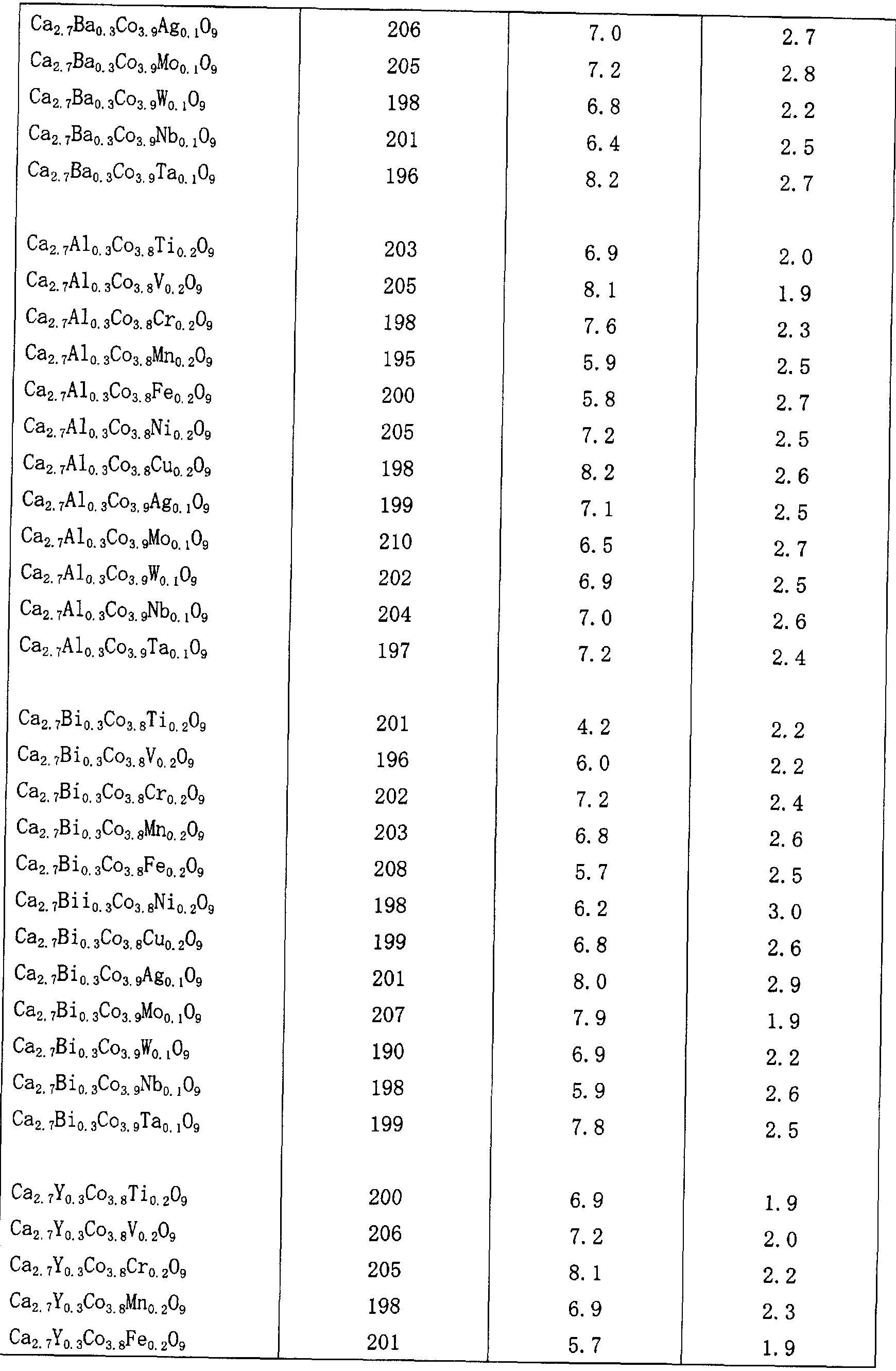


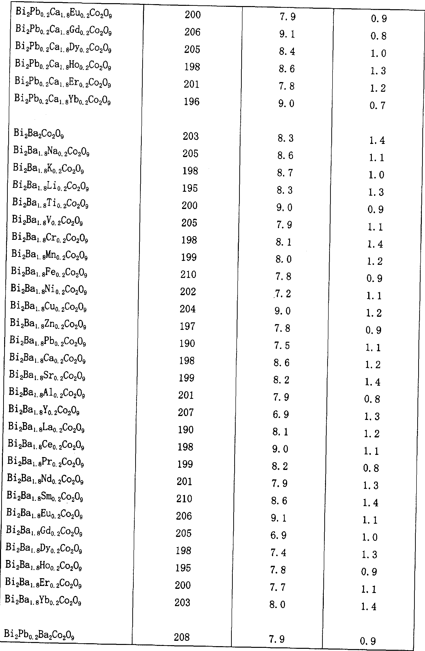


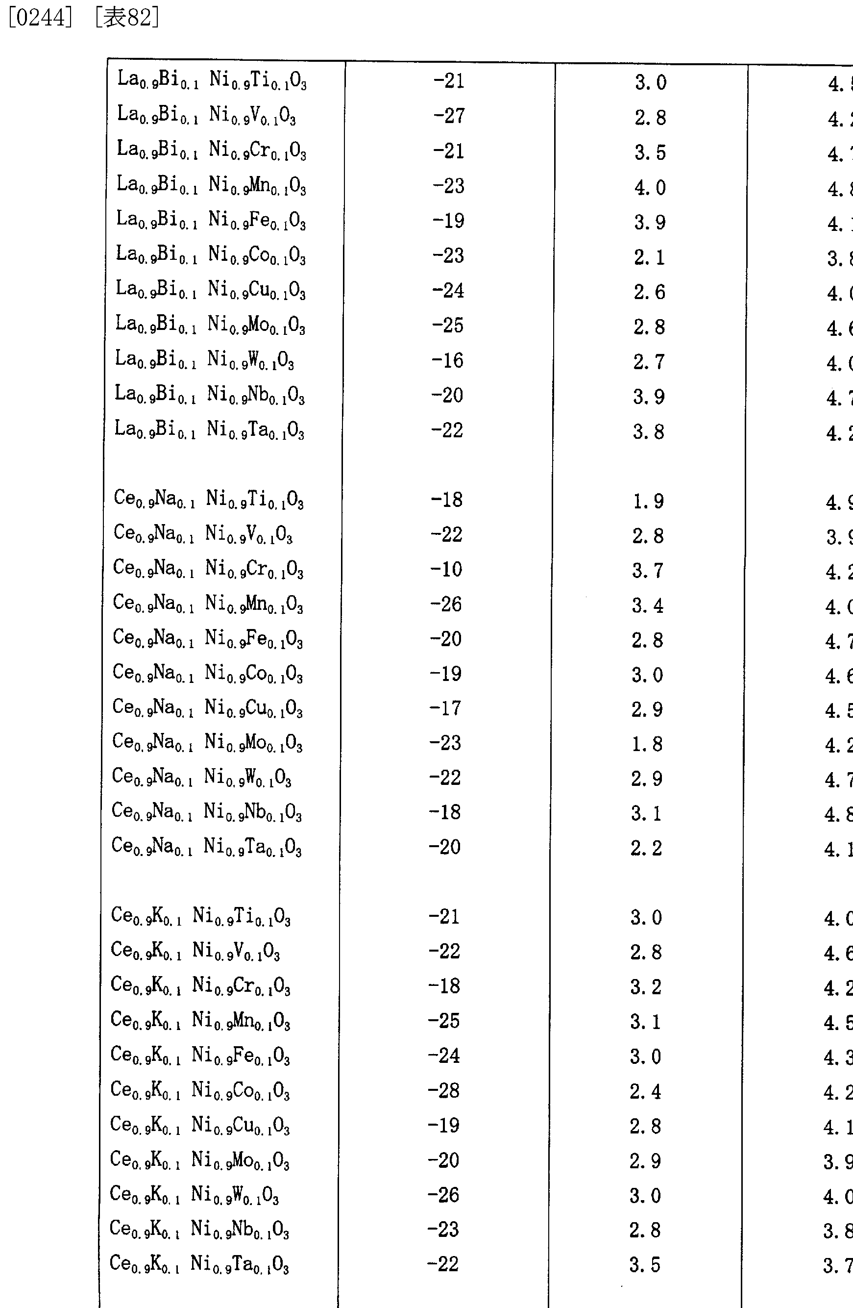


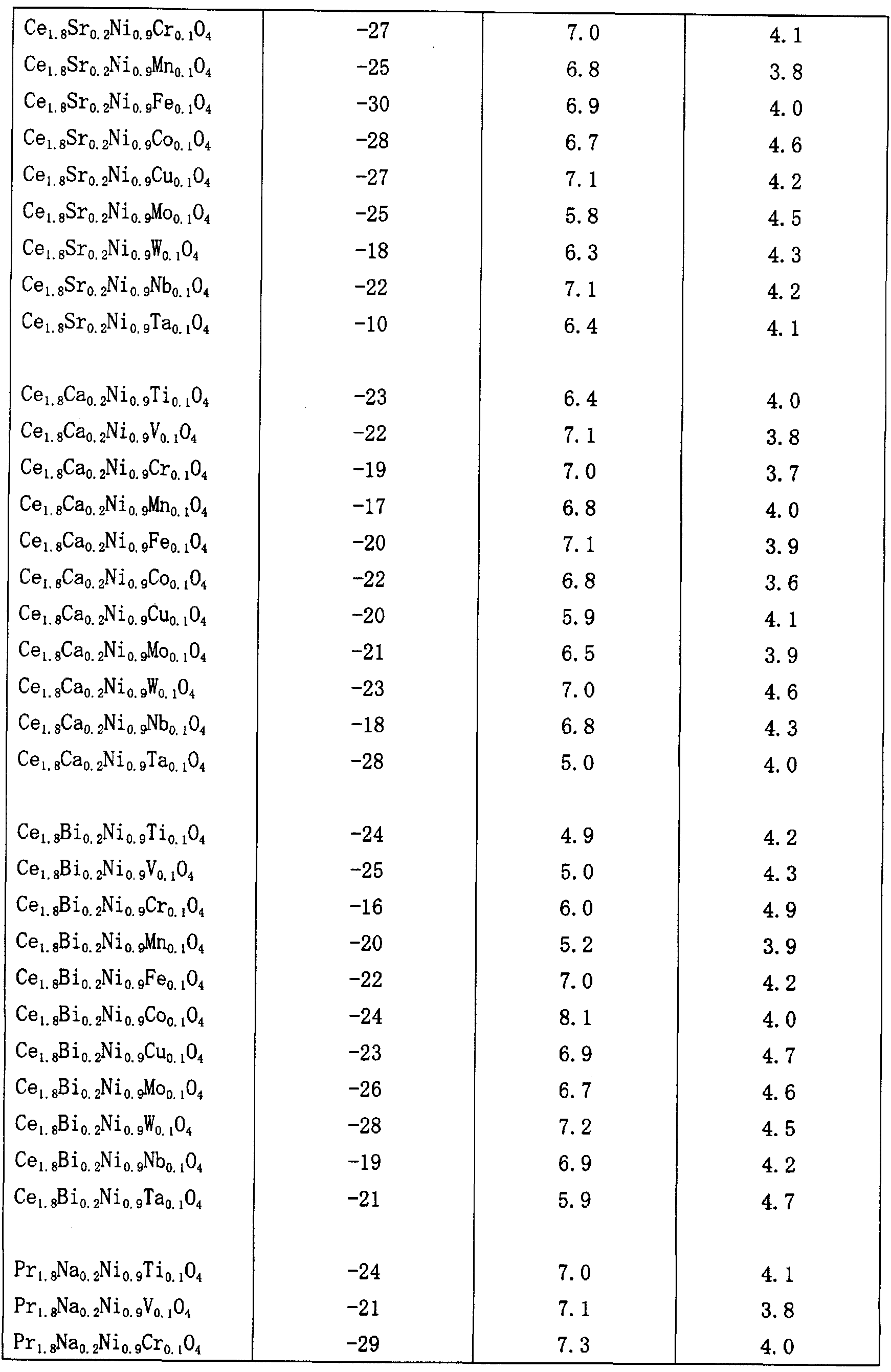


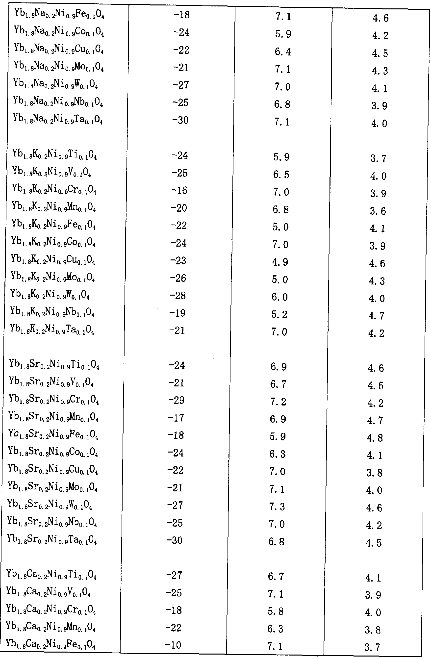

Claims
Priority Applications (3)
| Application Number | Priority Date | Filing Date | Title |
|---|---|---|---|
| US10/593,644 US7649139B2 (en) | 2004-03-25 | 2005-03-22 | Thermoelectric conversion element and thermoelectric conversion module |
| JP2006511459A JP4670017B2 (ja) | 2004-03-25 | 2005-03-22 | 熱電変換素子及び熱電変換モジュール |
| EP05727085A EP1737053B1 (en) | 2004-03-25 | 2005-03-22 | Thermoelectric conversion element and thermoelectric conversion module |
Applications Claiming Priority (2)
| Application Number | Priority Date | Filing Date | Title |
|---|---|---|---|
| JP2004-088290 | 2004-03-25 | ||
| JP2004088290 | 2004-03-25 |
Publications (1)
| Publication Number | Publication Date |
|---|---|
| WO2005093864A1 true WO2005093864A1 (ja) | 2005-10-06 |
Family
ID=35056496
Family Applications (1)
| Application Number | Title | Priority Date | Filing Date |
|---|---|---|---|
| PCT/JP2005/005133 WO2005093864A1 (ja) | 2004-03-25 | 2005-03-22 | 熱電変換素子及び熱電変換モジュール |
Country Status (4)
| Country | Link |
|---|---|
| US (1) | US7649139B2 (ja) |
| EP (1) | EP1737053B1 (ja) |
| JP (1) | JP4670017B2 (ja) |
| WO (1) | WO2005093864A1 (ja) |
Cited By (7)
| Publication number | Priority date | Publication date | Assignee | Title |
|---|---|---|---|---|
| JP2007150112A (ja) * | 2005-11-29 | 2007-06-14 | National Institute Of Advanced Industrial & Technology | コジェネレーションシステム及びその運転方法 |
| JP2009526401A (ja) * | 2006-02-10 | 2009-07-16 | デストロン フィアリング コーポレイション | 改良型低電力熱発電素子 |
| WO2009154019A1 (ja) * | 2008-06-19 | 2009-12-23 | 独立行政法人科学技術振興機構 | アルミニウム含有酸化亜鉛系n型熱電変換材料 |
| US7753584B2 (en) * | 2006-03-31 | 2010-07-13 | Mesoscribe Technologies, Inc. | Thermocouples |
| JP2017528905A (ja) * | 2014-07-17 | 2017-09-28 | エプコス アクチエンゲゼルシャフトEpcos Ag | 熱電素子用の材料および熱電素子用の材料の製造方法 |
| WO2018008507A1 (ja) * | 2016-07-04 | 2018-01-11 | 株式会社デンソー | 熱電発電装置 |
| CN113087514A (zh) * | 2021-04-16 | 2021-07-09 | 郑州轻工业大学 | 一种具有弛豫铁电特性的无铅多铁材料及其制备方法 |
Families Citing this family (43)
| Publication number | Priority date | Publication date | Assignee | Title |
|---|---|---|---|---|
| US7678701B2 (en) * | 2006-07-31 | 2010-03-16 | Eastman Kodak Company | Flexible substrate with electronic devices formed thereon |
| WO2008097385A1 (en) * | 2006-10-18 | 2008-08-14 | The Board Of Governors For Higher Education, State Of Rhode Island And Providence Plantations | Nano-composites for thermal barrier coatings and thermo-electric generators |
| JP4867618B2 (ja) * | 2006-11-28 | 2012-02-01 | 住友化学株式会社 | 熱電変換材料 |
| EP2319082B1 (en) | 2008-08-29 | 2017-11-15 | LG Chem, Ltd. | New compound semiconductor and producing method thereof, and solar cell and thermoelectric conversion element using the same |
| US9660165B2 (en) | 2008-08-29 | 2017-05-23 | Lg Chem, Ltd. | Thermoelectric conversion material and producing method thereof, and thermoelectric conversion element using the same |
| US9214618B2 (en) * | 2008-09-18 | 2015-12-15 | University Of Florida Research Foundation, Inc. | Miniature thermoelectric power generator |
| US20100072461A1 (en) * | 2008-09-24 | 2010-03-25 | Hanvision Co., Ltd. | Thermo-electric semiconductor device and method for manufacturing the same |
| US20100154855A1 (en) * | 2008-12-18 | 2010-06-24 | David Nemir | Thin walled thermoelectric devices and methods for production thereof |
| CN101483218B (zh) * | 2009-01-20 | 2011-03-09 | 深圳大学 | 一种温差电池的制作方法 |
| DE102009031302A1 (de) | 2009-06-30 | 2011-01-05 | O-Flexx Technologies Gmbh | Verfahren zur Herstellung von thermoelektrischen Schichten |
| US20110048488A1 (en) * | 2009-09-01 | 2011-03-03 | Gabriel Karim M | Combined thermoelectric/photovoltaic device and method of making the same |
| DE102010036188A1 (de) * | 2009-10-28 | 2011-05-05 | Sms Siemag Ag | Verfahren zur Energierückgewinnung in hüttentechnischen Anlagen und hüttentechnische Anlage auf Bais von Thermoelementen |
| KR101300758B1 (ko) * | 2011-08-30 | 2013-08-29 | 세종대학교산학협력단 | 발전용 고효율 π형 열전모듈 및 그의 제조 방법 |
| JP5913935B2 (ja) * | 2011-11-30 | 2016-05-11 | 日本サーモスタット株式会社 | 熱電変換モジュール |
| TWI473249B (zh) * | 2011-12-23 | 2015-02-11 | Taiwan Textile Res Inst | 光致冷裝置及其製備方法 |
| KR101384981B1 (ko) * | 2012-01-30 | 2014-04-14 | 연세대학교 산학협력단 | 열효율을 개선할 수 있는 구조를 갖는 열전 소자 |
| JP5670989B2 (ja) | 2012-11-20 | 2015-02-18 | アイシン高丘株式会社 | 熱電モジュールの製造方法 |
| WO2014114366A1 (de) * | 2013-01-24 | 2014-07-31 | O-Flexx Technologies Gmbh | Thermoelektrisches element sowie verfahren zu dessen herstellung |
| US9404175B2 (en) * | 2013-02-04 | 2016-08-02 | Blackberry Limited | Method of forming a target for deposition of doped dielectric films by sputtering |
| US10164164B2 (en) * | 2013-06-13 | 2018-12-25 | Brian Isaac Ashkenazi | Futuristic hybrid thermoelectric devices and designs and methods of using same |
| EP2958156B1 (en) * | 2013-10-04 | 2018-04-04 | LG Chem, Ltd. | Novel compound semiconductor and use thereof |
| US11024789B2 (en) | 2013-12-06 | 2021-06-01 | Sridhar Kasichainula | Flexible encapsulation of a flexible thin-film based thermoelectric device with sputter deposited layer of N-type and P-type thermoelectric legs |
| US10566515B2 (en) | 2013-12-06 | 2020-02-18 | Sridhar Kasichainula | Extended area of sputter deposited N-type and P-type thermoelectric legs in a flexible thin-film based thermoelectric device |
| US10141492B2 (en) | 2015-05-14 | 2018-11-27 | Nimbus Materials Inc. | Energy harvesting for wearable technology through a thin flexible thermoelectric device |
| US10290794B2 (en) | 2016-12-05 | 2019-05-14 | Sridhar Kasichainula | Pin coupling based thermoelectric device |
| US20180090660A1 (en) | 2013-12-06 | 2018-03-29 | Sridhar Kasichainula | Flexible thin-film based thermoelectric device with sputter deposited layer of n-type and p-type thermoelectric legs |
| US10367131B2 (en) | 2013-12-06 | 2019-07-30 | Sridhar Kasichainula | Extended area of sputter deposited n-type and p-type thermoelectric legs in a flexible thin-film based thermoelectric device |
| JP6134658B2 (ja) | 2014-01-22 | 2017-05-24 | 株式会社アツミテック | 熱電変換モジュール |
| KR102170479B1 (ko) * | 2014-02-14 | 2020-10-28 | 엘지이노텍 주식회사 | 열전환장치 |
| WO2015157513A1 (en) * | 2014-04-09 | 2015-10-15 | Cornell University | Misfit p-type transparent conductive oxide (tco) films, methods and applications |
| US9891114B2 (en) * | 2014-05-28 | 2018-02-13 | Hamilton Sundstrand Corporation | Flexible laminated thermocouple |
| DE102014012585B4 (de) * | 2014-08-26 | 2019-07-11 | Diehl & Eagle Picher Gmbh | Vorrichtung zur Bereistellung einer für den Betrieb wenigstens einer elektrischen Zündeinrichtung eines Geschosselements erforderlichen elektrischen Betriebsenergie |
| US10800665B1 (en) * | 2014-09-05 | 2020-10-13 | National Technology & Engineering Solutions Of Sandia, Llc | Redox-active oxide materials for thermal energy storage |
| WO2016039022A1 (ja) * | 2014-09-08 | 2016-03-17 | 富士フイルム株式会社 | 熱電変換素子および熱電変換モジュール |
| US11283000B2 (en) | 2015-05-14 | 2022-03-22 | Nimbus Materials Inc. | Method of producing a flexible thermoelectric device to harvest energy for wearable applications |
| US11276810B2 (en) | 2015-05-14 | 2022-03-15 | Nimbus Materials Inc. | Method of producing a flexible thermoelectric device to harvest energy for wearable applications |
| US10388847B2 (en) * | 2015-05-14 | 2019-08-20 | Nimbus Materials Inc. | Method of producing a flexible thermoelectric device to harvest energy for wearable applications |
| CN105823569B (zh) * | 2016-04-27 | 2018-10-30 | 西安交通大学 | 一种掺杂铬酸镧薄膜型热电偶及其制备方法 |
| US10991867B2 (en) | 2016-05-24 | 2021-04-27 | University Of Utah Research Foundation | High-performance terbium-based thermoelectric materials |
| US11152556B2 (en) | 2017-07-29 | 2021-10-19 | Nanohmics, Inc. | Flexible and conformable thermoelectric compositions |
| US10873116B2 (en) * | 2018-05-18 | 2020-12-22 | Lee Fei Chen | Charging device having thermoelectric module |
| RU189447U1 (ru) * | 2019-02-13 | 2019-05-22 | Федеральное государственное бюджетное учреждение науки Институт химии твердого тела Уральского отделения Российской академии наук | Термоэлектрический модуль |
| US11274363B2 (en) | 2019-04-22 | 2022-03-15 | Nxp Usa, Inc. | Method of forming a sputtering target |
Citations (10)
| Publication number | Priority date | Publication date | Assignee | Title |
|---|---|---|---|---|
| JPH03295281A (ja) * | 1990-04-12 | 1991-12-26 | Matsushita Electric Ind Co Ltd | 熱電装置及びその製造方法 |
| JPH07218348A (ja) * | 1994-02-08 | 1995-08-18 | Toppan Printing Co Ltd | 薄膜熱電対 |
| JP2002076447A (ja) * | 2000-08-29 | 2002-03-15 | National Institute Of Advanced Industrial & Technology | 熱電材料の性能評価方法 |
| JP2002335021A (ja) * | 2001-05-09 | 2002-11-22 | Japan Aviation Electronics Industry Ltd | 薄膜熱電対集積型熱電変換デバイス |
| JP2003008086A (ja) * | 2001-06-22 | 2003-01-10 | Idemitsu Kosan Co Ltd | 複合酸化物及びそれを用いた熱電変換素子 |
| JP2003133600A (ja) * | 2001-10-24 | 2003-05-09 | Kitagawa Ind Co Ltd | 熱電変換部材及びその製造方法 |
| JP2003282964A (ja) * | 2002-03-22 | 2003-10-03 | National Institute Of Advanced Industrial & Technology | n型熱電特性を有する複合酸化物 |
| JP2003306381A (ja) * | 2002-04-16 | 2003-10-28 | National Institute Of Advanced Industrial & Technology | 複合酸化物焼結体の製造方法 |
| JP2003306380A (ja) * | 2002-04-16 | 2003-10-28 | National Institute Of Advanced Industrial & Technology | 複合酸化物焼結体の製造方法 |
| JP2003324220A (ja) * | 2002-05-02 | 2003-11-14 | Toyota Motor Corp | レーザ蒸着法による酸化物系熱電変換薄膜の製造方法 |
Family Cites Families (11)
| Publication number | Priority date | Publication date | Assignee | Title |
|---|---|---|---|---|
| JPS57172784A (en) * | 1981-04-17 | 1982-10-23 | Univ Kyoto | Thermoelectric conversion element |
| US4859250A (en) * | 1985-10-04 | 1989-08-22 | Buist Richard J | Thermoelectric pillow and blanket |
| US5352299A (en) * | 1987-06-26 | 1994-10-04 | Sharp Kabushiki Kaisha | Thermoelectric material |
| JPH01262678A (ja) * | 1988-04-14 | 1989-10-19 | Murata Mfg Co Ltd | 積層熱電素子およびその製造方法 |
| JPH08186293A (ja) * | 1994-12-28 | 1996-07-16 | Seibu Gas Kk | 熱発電材料 |
| JP3295281B2 (ja) | 1995-08-10 | 2002-06-24 | キヤノン株式会社 | レーザー走査光学装置 |
| JP2001127350A (ja) * | 1999-08-17 | 2001-05-11 | Tokyo Gas Co Ltd | 熱電変換材料及び熱電変換素子 |
| JP3443641B2 (ja) * | 2000-02-10 | 2003-09-08 | 独立行政法人産業技術総合研究所 | 高いゼーベック係数と高い電気伝導度を有する複合酸化物 |
| JP3472813B2 (ja) * | 2000-07-18 | 2003-12-02 | 独立行政法人産業技術総合研究所 | 高いゼーベック係数と高い電気伝導度を有する複合酸化物 |
| JP2003335580A (ja) * | 2002-05-21 | 2003-11-25 | Univ Tohoku | 酸化物熱電材料 |
| US7732704B2 (en) * | 2003-10-08 | 2010-06-08 | National Institute Of Advanced Industrial Science And Technology | Conductive paste for connecting thermoelectric conversion material |
-
2005
- 2005-03-22 JP JP2006511459A patent/JP4670017B2/ja not_active Expired - Fee Related
- 2005-03-22 WO PCT/JP2005/005133 patent/WO2005093864A1/ja not_active Application Discontinuation
- 2005-03-22 US US10/593,644 patent/US7649139B2/en not_active Expired - Fee Related
- 2005-03-22 EP EP05727085A patent/EP1737053B1/en not_active Expired - Fee Related
Patent Citations (10)
| Publication number | Priority date | Publication date | Assignee | Title |
|---|---|---|---|---|
| JPH03295281A (ja) * | 1990-04-12 | 1991-12-26 | Matsushita Electric Ind Co Ltd | 熱電装置及びその製造方法 |
| JPH07218348A (ja) * | 1994-02-08 | 1995-08-18 | Toppan Printing Co Ltd | 薄膜熱電対 |
| JP2002076447A (ja) * | 2000-08-29 | 2002-03-15 | National Institute Of Advanced Industrial & Technology | 熱電材料の性能評価方法 |
| JP2002335021A (ja) * | 2001-05-09 | 2002-11-22 | Japan Aviation Electronics Industry Ltd | 薄膜熱電対集積型熱電変換デバイス |
| JP2003008086A (ja) * | 2001-06-22 | 2003-01-10 | Idemitsu Kosan Co Ltd | 複合酸化物及びそれを用いた熱電変換素子 |
| JP2003133600A (ja) * | 2001-10-24 | 2003-05-09 | Kitagawa Ind Co Ltd | 熱電変換部材及びその製造方法 |
| JP2003282964A (ja) * | 2002-03-22 | 2003-10-03 | National Institute Of Advanced Industrial & Technology | n型熱電特性を有する複合酸化物 |
| JP2003306381A (ja) * | 2002-04-16 | 2003-10-28 | National Institute Of Advanced Industrial & Technology | 複合酸化物焼結体の製造方法 |
| JP2003306380A (ja) * | 2002-04-16 | 2003-10-28 | National Institute Of Advanced Industrial & Technology | 複合酸化物焼結体の製造方法 |
| JP2003324220A (ja) * | 2002-05-02 | 2003-11-14 | Toyota Motor Corp | レーザ蒸着法による酸化物系熱電変換薄膜の製造方法 |
Non-Patent Citations (1)
| Title |
|---|
| See also references of EP1737053A4 * |
Cited By (11)
| Publication number | Priority date | Publication date | Assignee | Title |
|---|---|---|---|---|
| JP2007150112A (ja) * | 2005-11-29 | 2007-06-14 | National Institute Of Advanced Industrial & Technology | コジェネレーションシステム及びその運転方法 |
| JP2009526401A (ja) * | 2006-02-10 | 2009-07-16 | デストロン フィアリング コーポレイション | 改良型低電力熱発電素子 |
| US7753584B2 (en) * | 2006-03-31 | 2010-07-13 | Mesoscribe Technologies, Inc. | Thermocouples |
| WO2009154019A1 (ja) * | 2008-06-19 | 2009-12-23 | 独立行政法人科学技術振興機構 | アルミニウム含有酸化亜鉛系n型熱電変換材料 |
| JP2010003851A (ja) * | 2008-06-19 | 2010-01-07 | Japan Science & Technology Agency | アルミニウム含有酸化亜鉛系n型熱電変換材料 |
| US8454860B2 (en) | 2008-06-19 | 2013-06-04 | Japan Science And Technology Agency | Aluminum-containing zinc oxide-based n-type thermoelectric conversion material |
| JP2017528905A (ja) * | 2014-07-17 | 2017-09-28 | エプコス アクチエンゲゼルシャフトEpcos Ag | 熱電素子用の材料および熱電素子用の材料の製造方法 |
| WO2018008507A1 (ja) * | 2016-07-04 | 2018-01-11 | 株式会社デンソー | 熱電発電装置 |
| JP2018006609A (ja) * | 2016-07-04 | 2018-01-11 | 株式会社デンソー | 熱電発電装置 |
| CN113087514A (zh) * | 2021-04-16 | 2021-07-09 | 郑州轻工业大学 | 一种具有弛豫铁电特性的无铅多铁材料及其制备方法 |
| CN113087514B (zh) * | 2021-04-16 | 2022-05-10 | 郑州轻工业大学 | 一种具有弛豫铁电特性的无铅多铁材料及其制备方法 |
Also Published As
| Publication number | Publication date |
|---|---|
| JP4670017B2 (ja) | 2011-04-13 |
| US7649139B2 (en) | 2010-01-19 |
| US20070144573A1 (en) | 2007-06-28 |
| EP1737053A4 (en) | 2008-01-16 |
| JPWO2005093864A1 (ja) | 2008-02-14 |
| EP1737053B1 (en) | 2012-02-29 |
| EP1737053A1 (en) | 2006-12-27 |
| EP1737053A8 (en) | 2007-10-03 |
Similar Documents
| Publication | Publication Date | Title |
|---|---|---|
| WO2005093864A1 (ja) | 熱電変換素子及び熱電変換モジュール | |
| JP4446064B2 (ja) | 熱電変換素子及び熱電変換モジュール | |
| JP4797148B2 (ja) | 熱電変換材料接続用導電性ペースト | |
| WO2005083808A1 (ja) | 熱電変換デバイス、およびこれを用いた冷却方法および発電方法 | |
| JP3472813B2 (ja) | 高いゼーベック係数と高い電気伝導度を有する複合酸化物 | |
| JP3867134B2 (ja) | 複合酸化物焼結体の製造方法 | |
| JP4457215B2 (ja) | 熱電発電機能を有する管材 | |
| JP3896479B2 (ja) | 複合酸化物焼結体の製造方法 | |
| JP2011198989A (ja) | 熱電変換材料及びその製造方法、熱電変換モジュール | |
| US7554029B2 (en) | Complex oxide having p-type thermoelectric characteristics | |
| JP4595123B2 (ja) | 熱電発電装置 | |
| JP2003306381A (ja) | 複合酸化物焼結体の製造方法 | |
| JP4051441B2 (ja) | 薄膜状熱電変換材料及びその形成方法 | |
| WO2005044730A1 (ja) | n型熱電変換特性を有する複合酸化物 | |
| JP2007149996A (ja) | デラフォッサイト構造を持つ層状酸化物熱電材料 | |
| JP4595071B2 (ja) | 熱電変換素子、熱電変換モジュール及び熱電変換方法 | |
| JP3586716B2 (ja) | 高い熱電変換効率を有する複合酸化物 | |
| WO2003000605A1 (fr) | Procede de production d'un monocristal d'oxyde composite | |
| JP2005223307A (ja) | 酸化物系熱電変換膜、及び酸化物系熱電変換膜の作製方法 | |
| JP4275172B2 (ja) | デラフォッサイト構造を持つ層状酸化物熱電材料 | |
| JP2004107151A (ja) | 金属酸化物単結晶及び金属酸化物単結晶の製造方法 |
Legal Events
| Date | Code | Title | Description |
|---|---|---|---|
| AK | Designated states |
Kind code of ref document: A1 Designated state(s): AE AG AL AM AT AU AZ BA BB BG BR BW BY BZ CA CH CN CO CR CU CZ DE DK DM DZ EC EE EG ES FI GB GD GE GH GM HR HU ID IL IN IS JP KE KG KP KR KZ LC LK LR LS LT LU LV MA MD MG MK MN MW MX MZ NA NI NO NZ OM PG PH PL PT RO RU SC SD SE SG SK SL SM SY TJ TM TN TR TT TZ UA UG US UZ VC VN YU ZA ZM ZW |
|
| AL | Designated countries for regional patents |
Kind code of ref document: A1 Designated state(s): BW GH GM KE LS MW MZ NA SD SL SZ TZ UG ZM ZW AM AZ BY KG KZ MD RU TJ TM AT BE BG CH CY CZ DE DK EE ES FI FR GB GR HU IE IS IT LT LU MC NL PL PT RO SE SI SK TR BF BJ CF CG CI CM GA GN GQ GW ML MR NE SN TD TG |
|
| 121 | Ep: the epo has been informed by wipo that ep was designated in this application | ||
| WWE | Wipo information: entry into national phase |
Ref document number: 2006511459 Country of ref document: JP |
|
| WWE | Wipo information: entry into national phase |
Ref document number: 2005727085 Country of ref document: EP Ref document number: 2007144573 Country of ref document: US Ref document number: 10593644 Country of ref document: US |
|
| NENP | Non-entry into the national phase |
Ref country code: DE |
|
| WWW | Wipo information: withdrawn in national office |
Country of ref document: DE |
|
| WWP | Wipo information: published in national office |
Ref document number: 2005727085 Country of ref document: EP |
|
| WWP | Wipo information: published in national office |
Ref document number: 10593644 Country of ref document: US |