WO2003046523A1 - Plastic identifying method - Google Patents
Plastic identifying method Download PDFInfo
- Publication number
- WO2003046523A1 WO2003046523A1 PCT/JP2002/012290 JP0212290W WO03046523A1 WO 2003046523 A1 WO2003046523 A1 WO 2003046523A1 JP 0212290 W JP0212290 W JP 0212290W WO 03046523 A1 WO03046523 A1 WO 03046523A1
- Authority
- WO
- WIPO (PCT)
- Prior art keywords
- infrared absorption
- range
- wave number
- absorption spectrum
- plastic
- Prior art date
Links
- 238000000034 method Methods 0.000 title claims abstract description 123
- 229920003023 plastic Polymers 0.000 title claims abstract description 102
- 239000004033 plastic Substances 0.000 title claims abstract description 102
- 238000000862 absorption spectrum Methods 0.000 claims abstract description 122
- 239000003063 flame retardant Substances 0.000 claims abstract description 53
- 239000000126 substance Substances 0.000 claims abstract description 53
- RNFJDJUURJAICM-UHFFFAOYSA-N 2,2,4,4,6,6-hexaphenoxy-1,3,5-triaza-2$l^{5},4$l^{5},6$l^{5}-triphosphacyclohexa-1,3,5-triene Chemical compound N=1P(OC=2C=CC=CC=2)(OC=2C=CC=CC=2)=NP(OC=2C=CC=CC=2)(OC=2C=CC=CC=2)=NP=1(OC=1C=CC=CC=1)OC1=CC=CC=C1 RNFJDJUURJAICM-UHFFFAOYSA-N 0.000 claims abstract description 46
- 238000001228 spectrum Methods 0.000 claims description 55
- 238000012360 testing method Methods 0.000 claims description 34
- 239000004793 Polystyrene Substances 0.000 claims description 22
- 238000010521 absorption reaction Methods 0.000 claims description 21
- 229920002223 polystyrene Polymers 0.000 claims description 21
- 238000005070 sampling Methods 0.000 claims description 21
- VEORPZCZECFIRK-UHFFFAOYSA-N 3,3',5,5'-tetrabromobisphenol A Chemical compound C=1C(Br)=C(O)C(Br)=CC=1C(C)(C)C1=CC(Br)=C(O)C(Br)=C1 VEORPZCZECFIRK-UHFFFAOYSA-N 0.000 claims description 18
- XECAHXYUAAWDEL-UHFFFAOYSA-N acrylonitrile butadiene styrene Chemical compound C=CC=C.C=CC#N.C=CC1=CC=CC=C1 XECAHXYUAAWDEL-UHFFFAOYSA-N 0.000 claims description 13
- 229920000122 acrylonitrile butadiene styrene Polymers 0.000 claims description 13
- 239000004676 acrylonitrile butadiene styrene Substances 0.000 claims description 13
- 239000004743 Polypropylene Substances 0.000 claims description 7
- 239000003973 paint Substances 0.000 claims description 7
- 229920001155 polypropylene Polymers 0.000 claims description 7
- 229920002678 cellulose Polymers 0.000 claims description 6
- 229910052909 inorganic silicate Inorganic materials 0.000 claims description 6
- -1 polypropylene Polymers 0.000 claims description 6
- 102000004169 proteins and genes Human genes 0.000 claims description 6
- 108090000623 proteins and genes Proteins 0.000 claims description 6
- JYEUMXHLPRZUAT-UHFFFAOYSA-N 1,2,3-triazine Chemical compound C1=CN=NN=C1 JYEUMXHLPRZUAT-UHFFFAOYSA-N 0.000 claims description 5
- 239000001913 cellulose Substances 0.000 claims description 5
- 239000003925 fat Substances 0.000 claims description 5
- 230000001678 irradiating effect Effects 0.000 claims description 5
- 239000003921 oil Substances 0.000 claims description 5
- VGGSQFUCUMXWEO-UHFFFAOYSA-N Ethene Chemical compound C=C VGGSQFUCUMXWEO-UHFFFAOYSA-N 0.000 claims description 3
- 239000005977 Ethylene Substances 0.000 claims description 3
- 235000001892 vitamin D2 Nutrition 0.000 claims description 3
- 239000000654 additive Substances 0.000 abstract description 7
- 239000000049 pigment Substances 0.000 abstract 1
- 238000001514 detection method Methods 0.000 description 13
- 238000004064 recycling Methods 0.000 description 8
- 238000005259 measurement Methods 0.000 description 7
- 238000011109 contamination Methods 0.000 description 6
- XLYOFNOQVPJJNP-UHFFFAOYSA-N water Substances O XLYOFNOQVPJJNP-UHFFFAOYSA-N 0.000 description 5
- 235000010980 cellulose Nutrition 0.000 description 4
- 239000000463 material Substances 0.000 description 4
- PPBRXRYQALVLMV-UHFFFAOYSA-N Styrene Natural products C=CC1=CC=CC=C1 PPBRXRYQALVLMV-UHFFFAOYSA-N 0.000 description 3
- 238000002835 absorbance Methods 0.000 description 2
- 230000000996 additive effect Effects 0.000 description 2
- 239000000428 dust Substances 0.000 description 2
- 235000014593 oils and fats Nutrition 0.000 description 2
- 238000012545 processing Methods 0.000 description 2
- 239000002994 raw material Substances 0.000 description 2
- 230000001846 repelling effect Effects 0.000 description 2
- 239000011347 resin Substances 0.000 description 2
- 229920005989 resin Polymers 0.000 description 2
- 238000004611 spectroscopical analysis Methods 0.000 description 2
- NLHHRLWOUZZQLW-UHFFFAOYSA-N Acrylonitrile Chemical compound C=CC#N NLHHRLWOUZZQLW-UHFFFAOYSA-N 0.000 description 1
- 241000255925 Diptera Species 0.000 description 1
- 238000004566 IR spectroscopy Methods 0.000 description 1
- 241000270666 Testudines Species 0.000 description 1
- 230000005540 biological transmission Effects 0.000 description 1
- 239000003638 chemical reducing agent Substances 0.000 description 1
- 238000004040 coloring Methods 0.000 description 1
- 229920001577 copolymer Polymers 0.000 description 1
- 230000006866 deterioration Effects 0.000 description 1
- 230000002542 deteriorative effect Effects 0.000 description 1
- 238000010586 diagram Methods 0.000 description 1
- 230000000694 effects Effects 0.000 description 1
- 230000007613 environmental effect Effects 0.000 description 1
- 230000012447 hatching Effects 0.000 description 1
- 230000007774 longterm Effects 0.000 description 1
- 238000000691 measurement method Methods 0.000 description 1
- 238000012986 modification Methods 0.000 description 1
- 230000004048 modification Effects 0.000 description 1
- 239000000178 monomer Substances 0.000 description 1
- 238000000465 moulding Methods 0.000 description 1
- 230000035699 permeability Effects 0.000 description 1
- 230000000704 physical effect Effects 0.000 description 1
- 229920000642 polymer Polymers 0.000 description 1
- 230000001681 protective effect Effects 0.000 description 1
- 238000005979 thermal decomposition reaction Methods 0.000 description 1
Classifications
-
- G—PHYSICS
- G01—MEASURING; TESTING
- G01N—INVESTIGATING OR ANALYSING MATERIALS BY DETERMINING THEIR CHEMICAL OR PHYSICAL PROPERTIES
- G01N21/00—Investigating or analysing materials by the use of optical means, i.e. using sub-millimetre waves, infrared, visible or ultraviolet light
- G01N21/17—Systems in which incident light is modified in accordance with the properties of the material investigated
- G01N21/25—Colour; Spectral properties, i.e. comparison of effect of material on the light at two or more different wavelengths or wavelength bands
- G01N21/31—Investigating relative effect of material at wavelengths characteristic of specific elements or molecules, e.g. atomic absorption spectrometry
- G01N21/35—Investigating relative effect of material at wavelengths characteristic of specific elements or molecules, e.g. atomic absorption spectrometry using infrared light
- G01N21/3563—Investigating relative effect of material at wavelengths characteristic of specific elements or molecules, e.g. atomic absorption spectrometry using infrared light for analysing solids; Preparation of samples therefor
-
- G—PHYSICS
- G01—MEASURING; TESTING
- G01N—INVESTIGATING OR ANALYSING MATERIALS BY DETERMINING THEIR CHEMICAL OR PHYSICAL PROPERTIES
- G01N21/00—Investigating or analysing materials by the use of optical means, i.e. using sub-millimetre waves, infrared, visible or ultraviolet light
- G01N21/17—Systems in which incident light is modified in accordance with the properties of the material investigated
- G01N21/55—Specular reflectivity
- G01N21/552—Attenuated total reflection
-
- G—PHYSICS
- G01—MEASURING; TESTING
- G01N—INVESTIGATING OR ANALYSING MATERIALS BY DETERMINING THEIR CHEMICAL OR PHYSICAL PROPERTIES
- G01N2201/00—Features of devices classified in G01N21/00
- G01N2201/12—Circuits of general importance; Signal processing
- G01N2201/129—Using chemometrical methods
Definitions
- the present invention relates to a method for identifying a lock.
- Plastic has many advantages, such as lightness and durability, good transparency, good water permeability, and easy coloring and molding. Is increasing. However, along with this, the amount of plastic that is discarded is steadily increasing, and the increase in environmental load is becoming a social problem. In order to solve these problems and effectively use limited resources, plastic recycling methods have been actively studied in recent years.
- Plastic recycling methods include, for example, material recycling as a raw material for new molded articles by repelling, thermal recycling to burn and recover heat, thermal decomposition to use as a blast furnace reducing agent, and oils and fats / monomers. There is chemical recycling, which decomposes and re-uses it as a raw material for plastics.
- infrared spectroscopy using near infrared has been used to identify the type of plastic.
- Such spectroscopy is mainly used.
- the plastic being identified is black (for example, the plastic used in many home appliances such as the housing of a television receiver is black)
- the irradiated near infrared rays are absorbed. For this reason, it is difficult to obtain an infrared absorption spectrum.
- the obtained infrared absorption spectrum and the infrared absorption spectrum of various standard plastics are used.
- the comparison with the torque group is performed.
- the infrared absorption spectrum of the standard plastic that best matches the obtained infrared absorption spectrum is searched, and the type of plastic is identified.
- Plastics that are subject to recycling often contain additives such as flame retardants.
- standard plastics to be compared and matched are basically polymers alone, and plastics containing additives have not been included in the comparison and matching.
- the infrared absorption spectrum of standard plastic is usually data obtained by a method of transmitting infrared light to an identification object (transmission method). Disclosure of the invention
- the present invention can more accurately identify the type of plastic even when the identification object is colored or when the identification object contains an additive or the like.
- the purpose is to provide a method for identifying plastic that can be used.
- the method for identifying plastic comprises the steps of: (i) irradiating an infrared ray having a predetermined wave number to an identifier including plastic, and measuring the intensity of the infrared ray totally reflected by the identifier. Especially Thus, obtaining a first infrared absorption spectrum;
- the predetermined substance group is a substance group containing plastic
- Each of the infrared absorption spectrums of the infrared absorption spectrum group is configured such that an infrared ray having a predetermined wave number is incident on each of the substances included in the predetermined substance group, and that the substance is totally reflected.
- the collation is performed by comparing a peak of the first infrared absorption spectrum with a peak of each infrared absorption spectrum of the infrared absorption spectrum group.
- the step (i) may include:
- the step (i) may include:
- (i-A) a step of sampling a test piece from the identification object; and (i-B) an infrared ray having a predetermined wave number is incident on a first surface of the test piece corresponding to a surface of the identification object, and Obtaining a second infrared absorption spectrum by measuring the intensity of the infrared light totally reflected on the first surface;
- (i-C) an intensity of the infrared light having a predetermined wave number incident on the second surface of the test piece, which is first exposed at the time of the sampling, and totally reflected on the second surface.
- the predetermined substance group may be a substance group including at least one selected from acrylonitrile-butadiene-styrene copolymer, polypropylene, and polystyrene.
- the predetermined substance group may be a substance group containing a plastic containing a flame retardant.
- the plastic containing the flame retardant may be an acrylonitrile butadiene styrene copolymer containing a tetrabromobisphenol A (TBA) -based flame retardant.
- TSA tetrabromobisphenol A
- the plastic containing the flame retardant may be polystyrene containing at least one flame retardant selected from a decap mouth flame retardant, a TBA flame retardant, a triazine flame retardant, and an ethylene bis flame retardant. You may.
- said first infrared absorption spectrum is, wave number 9 0 6 cm- 1 Power et 9 1 4 cm- 1 range, wavenumber 1 0 2 3 cm - 1 from 1 0 3 1 cm- 1 range and the wave number 2 2 34 cm- 1 has a peak at 2 2 42 cm- 1 range, and the wave number 1 0 0 0 cm- mosquitoes, et 1 00 8 the maximum peak intensity existing in the range of cm 1, when divided by the maximum peak intensity existing in the range of wave number 1 0 2 3 cm- 1 of 1 0 3 1 cm- 1 is at 0.5 or less
- the identification object may be identified as an acrylonitrile lylbutadiene styrene copolymer.
- said first infrared absorption spectrum is, wave number 1 3 7 3 cm- 1 from 1 3 8 1 cm- 1 range, wavenumber 2 9 1 3 cm- if having a peak 1 from the force et 2 9 2 1 cm- 1 range
- the identification object is a polypropylene May be identified.
- the first infrared absorption spectrum / ray may have a wave number in a range of 1368 cm- 1 to 1376 cm- 1 and a wave number of 10 2 3 has a peak from cm _ 1 to 1 0 3 1 cm- 1 range, and the maximum peak intensity existing in the range of wave number 1 0 0 0 cm- 1 1 of 0 0 8 c m_ 1,
- the identification object is a TBA-based flame retardant. It may be identified as a polystyrene which does not contain polystyrene.
- said first infrared absorption spectrum Honoré is, wave number 1 3 6 8 cm- 1 Power et al 1 3 76 cm _ 1 ranging and wavenumber 1 0 2 3 cm- 1 force, et 1 0 3 has a peak at 1 cm _ 1 range, and, wavenumber 1 3 4 8 cm- 1 force, does not have a peak in the range of al 1 3 5 6 cm- 1,
- the identification object may be identified as a polystyrene containing no flame retardant.
- the first infrared absorption spectrum 7 may have a wave number of 1349 cm ⁇ 1, a range of 1357 cm ⁇ 1 , etc. Having a peak in the range of wave number 10 23 cm _ 1 to 103 1 cm- 1 , and having no peak in the range of wave number 9 07 cm- 1 to 9 15 cm- 1 , And the maximum peak intensity which exists in the range of wave number 1 0 0 0 cm- 1 to 1 0 8 cm 1 , and the wave number 1 0 2 3 cm- 1 : in the range of 10 3 1 cm- 1 When the value divided by the maximum peak intensity is 0.5 or less, the identification object may be identified as polystyrene containing a decapro-based flame retardant.
- said first infrared absorption spectrum Honoré is, wave number 1 0 0 0 cm- 1 from 1 0 0 8 cm _ 1 ranging and wavenumber 1 0 2 3 cm— 1 force and a peak in the range of 10 3 1 cm— 1 ; and
- the maximum peak intensity in the range of 1 0 0 0 cm- 1 to 1 0 8 cm- 1 wave number is the maximum in the range of 1 0 2 3 cm- 1 to 1 0 3 1 cm- 1 wave number.
- the identification object may be identified as polystyrene containing a TBA-based flame retardant.
- said first infrared absorption spectrum is, wave number 1 3 5 6 cm- 1 from 1 3 64 cm- 1 range, wavenumber 1 2 2 7 cm - 1 power et al. 1 2 3 5 cm- 1 of the range, the wave number 1 0 8 5 cm- 1 power et al.
- the identification object may be identified as polystyrene containing a triazine-based flame retardant.
- said first infrared absorption spectrum is, wave number 1 3 6 9 cm- 1 from 1 3 7 7 cm- 1 range, wavenumber 1 1 3 7 cm— 1 force to 1 1 4 5 cm— 1 range, wave number 74 2 cm— 1 to 7500 cm— 1 and wave number 1 0 2 3 cm— 1 force to 1 0 3 1 cm _1 range It has a peak at and the maximum peak intensity existing in the range of wave number 1 0 0 0 cm- 1 of 1 0 0 8 cm- 1, wave number 1 0 2 3 cm- 1 1 0 3 1 cm- 1 When the value divided by the maximum peak intensity existing in the range of 0.5 or less is 0.5 or less, the identification object may be identified as polystyrene containing an ethylenebis-based flame retardant.
- the third infrared absorption spectrum is obtained by excluding the peak of the infrared absorption spectrum of the plastic identified as being contained in the object from the peak of the first infrared absorption spectrum. Obtaining the spectrum, (y) comparing the third infrared absorption spectrum with the group of infrared absorption spectra to identify an adhering substance adhering to the surface of the identification object. May be further included.
- the deposit may include at least one selected from fats and oils, proteins, paints, cellulose, and inorganic silicates.
- the third infrared absorption spectrum is the case with peak in the range of wave number 1 7 3 6 cm one 1 Power et al. 1 744 cm _ 1
- the deposit may be identified as at least one selected from fats and oils and paints.
- the third infrared absorption spectrum Honoré is, wave number 1 64 6 cm- 1 force, et 1 6 54 cm- 1 range and a wavenumber of 1 5 4 1 cm- if having a peak 1 from 1 54 9 cm- 1 range, the deposit may be identified as a protein.
- the third infrared absorption spectrum Honoré has wavenumber 1 00 0 cm _ 1 power, the peak in the range of al 1 1 0 0 cm- 1
- the deposit may be identified as at least one selected from cellulose and inorganic silicate.
- (X) a step of obtaining a fourth infrared absorption spectrum by removing the peak of the first infrared absorption spectrum from the peak of the second infrared absorption spectrum;
- (Y) a step of identifying the attached matter adhering to the surface of the identification object by comparing the fourth infrared absorption spectrum with the infrared absorption spectrum group; May be further included.
- FIG. 1 is a cross-sectional view showing an example of a detection unit capable of implementing the plastic identification method of the present invention.
- FIG. 2 is a schematic diagram showing an example of an identification device capable of performing the plastic identification method of the present invention.
- FIG. 3 shows the results measured using the plastic identification method of the present invention. It is an example of an infrared absorption spectrum.
- FIG. 4 is an example of an infrared absorption spectrum measured using the plastic identification method of the present invention.
- the method for identifying plastic according to the present invention comprises:
- a first infrared absorption spectrum is obtained by irradiating infrared rays having a predetermined wave number to an identification object containing plastic and measuring the intensity of the infrared light totally reflected by the identification object.
- the predetermined substance group is a substance group containing plastic.
- the infrared absorption spectrum of the infrared absorption spectrum group includes an infrared ray having a predetermined wave number incident on each substance included in the predetermined substance group, and 4 is an infrared absorption spectrum obtained by measuring the intensity of the infrared light totally reflected.
- the comparison is performed by comparing the peak of the first infrared absorption spectrum with the peak of each infrared absorption spectrum of the infrared absorption spectrum group. .
- the type of plastic contained in the identification object can be identified with higher accuracy even when the identification object is colored or when the identification object contains a flame retardant. be able to.
- the method of performing the step (i) is not particularly limited.
- a detection unit combining an infrared light source, a lens, a prism, a detector, and the like may be used.
- FIG. 1 shows an example of the detection unit.
- the infrared ray having the predetermined wave number (hereinafter, also referred to as infrared ray) is, for example, light having a wave number in a range of 400 cm ⁇ 1 to 700 cm ⁇ 1 (in this case, the light Is a light generally classified as a mid-infrared ray.)
- the detecting unit 1 shown in FIG. 1 includes a light source 2, a prism 3, and a detector 4.
- the infrared light 6 emitted from the light source 2 is incident on the identification object 5 by the prism 3. At this time, the incident angle ⁇ ⁇ shown in FIG.
- FIG. 1 is a cross-sectional view showing a cross section of the detection unit 1, hatching is omitted for easy understanding of the drawing.
- an ATR Attene uat ted T o a l R e f le c t io n
- This measurement method uses an ATR prism, which is a high-refractive index medium, to apply infrared light to the surface of an object at an incident angle equal to or greater than the critical angle, and to measure the intensity of total reflected infrared light.
- the method of performing the step (ii) is not particularly limited.
- a spectrum group measured for a predetermined substance group may be stored in a database or the like in advance, and may be collated one after another with the first spectrum obtained in the step (i).
- the predetermined substance group may be any substance group including plastic.
- the measurement of the stationary group with respect to the predetermined substance group may be performed by using the same method as the method of performing the above-described step (i).
- the matching may be performed by comparing peaks of the contrasting spectrum.
- the comparison of the peaks may be performed on, for example, the peak position and the peak intensity.
- the substance showing the spectrum closest to the first spectrum in the predetermined substance group can be the plastic included in the identification object.
- the step (i) includes:
- the first infrared absorption spectrum is obtained by irradiating an infrared ray of a predetermined wave number to the test piece and measuring the intensity of the infrared ray totally reflected on the test piece. And a step.
- an infrared ray is incident on a test piece sampled from the identification object, instead of directly entering the infrared ray on the identification object. That Therefore, even when the size of the identification object body is large, the identification work is easy.
- the size and shape of the test piece can be optimized according to the detection unit regardless of the shape of the identification object body, the type of plastic contained in the identification object can be identified more accurately and stably. can do. It is also an identification method suitable for continuous identification processing.
- the step (i) includes:
- an infrared ray having a predetermined wave number is incident on the second surface exposed for the first time at the time of the sampling, and the intensity of the infrared ray totally reflected on the second surface is measured.
- the method may include a step of obtaining the first infrared absorption spectrum by measuring.
- the turtle is measured on at least two surfaces of the test piece. Also, one of the measurement surfaces was the first surface that was exposed to the outside during sampling. Therefore, even if the surface of the object has deteriorated due to long-term use, or if there is foreign matter such as dust on the surface of the object, it is included in the object with higher accuracy and stability.
- the type of plastic can be identified. As will be described later, the degree of contamination on the surface of the identification object can be quantified by using this identification method.
- the above identification method can be implemented, for example, by using the identification device shown in FIG.
- the identification device shown in FIG. 2 includes a sampling unit 8 for sampling a test piece 7 from an identification object 12 and a plug included in the test piece 7.
- An identification section 9 having a detection section 1 for identifying the type of stick is provided, and a transport section 10 for transporting a test piece from the sampling section 8 to the detection section 1 is provided.
- the sampling section 8 may be provided with, for example, a punch press. In this case, the sampling of the test piece 1 can be easily performed.
- the identification unit 9 may include, for example, the detection unit illustrated in FIG.
- the transport unit 10 may include, for example, a chucking unit 11. When the chucking portion 11 is provided, measurement on at least two surfaces of the test piece 1 becomes easier.
- the first spectrum may be compared with the spectrum group by using, for example, the identification unit 9. In this case, the data of the spectrum group is stored in the identification unit 9 in advance, and after the first spectrum is measured by the detection unit 4, the data of the first spectrum is sent to the identification unit 9 and collated.
- the predetermined substance group is a substance group containing at least one selected from acrylonitrile butadiene styrene copolymer (ABS), polypropylene (PP) and polystyrene (PS). There may be. These plastics are plastics that are widely used for housings of home appliances.
- the predetermined substance group may be a substance group containing a plastic containing a flame retardant.
- the plastics contained in the identities that are actually recycled contain flame retardants.
- the comparison of the measured first spectrum with the spectrum of the standard plastic included in the spectrum group alone will result in the plastic
- the type may be difficult to identify. Therefore, by adopting such an identification method, it is possible to identify the type of plastic contained in the identification object with higher accuracy even when the identification object contains a flame retardant.
- the plastic containing the flame retardant may be ABS containing a tetrabromobisphenol A (TBA) -based flame retardant.
- the plastic containing the flame retardant is PS containing at least one flame retardant selected from decap mouth flame retardants, TBA flame retardants, triazine flame retardants and ethylene bis flame retardants. Good. These plastics are plastics that are widely used for housings of home appliances.
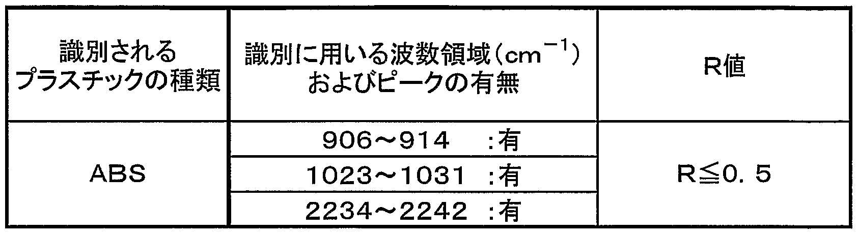
- the first infrared absorption spectrum may have a wave number in a range of 906 cm- 1 to 914 cm- 1 and a wave number of 10 23 - 1 power
- et 1 0 3 1 has a range and a wavenumber 2 2 34 peaks from cm _ 1 to 2 24 2 cm- 1 in the range of cm _1
- the wave number 1 0 0 0 cm- 1 power et al 1 0 0 the maximum peak intensity existing in 8 cm one 1, and divided by the maximum peak intensity existing in the range of wave number 1 0 2 3 cm- 1 of 1 0 3 1 cm- 1 is 0.5 or less
- the identification object may be identified as ABS.
- Table 1 summarizes the above ABS identification methods. However, the R values in Table 1, wave number 1 0 0 0 c ra- 1 Power et al 1 0 0 8 cm- maximum peak intensity existing in the first range, wavenumber 1 0 2 3 cm- 1 from 1 0 3 It is the value obtained by dividing by the maximum peak intensity existing in the range of 1 cm- 1 .
- the R values in this specification are all the same.
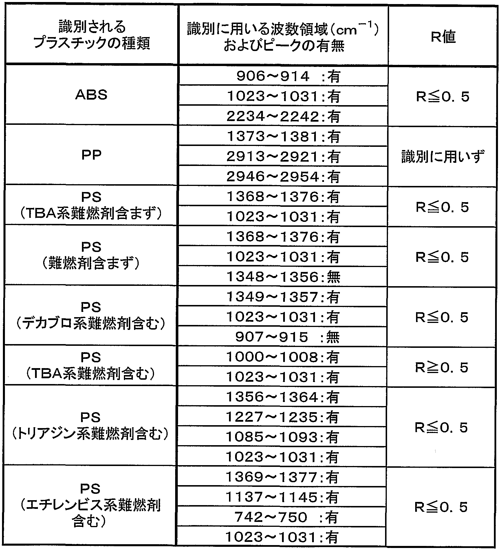
- the identification shown in Table 2 below may be performed in the step (ii).
- the description method in Table 2 is the same as in Table 1 described above. That is, for example, in the above described process (ii), the first infrared absorption scan Bae-vector is, wave number 1 3 7 3 cm- 1 from 1 3 8 1 cm _ 1 range, wavenumber 2 9 1 3 cm — 1 force and 2921 cm- 1 range and wave number 2946 cm- 1 force and 2954 4 cm-If there is a peak in the range of 1 , the identified object is identified as PP May be.
- Table 2 also describes the ABS identification method shown in Table 1.
- the maximum peak intensity existing in the range of the wave number 10 00 cm— 1 to 100 8 cm— 1 and the wave number 10 23 cm— 1 to 103 1 cm— 1 was determined. According to this method, it is possible to more reliably identify whether or not ABS and PS contain a TBA-based flame retardant.
- the spectra shown in FIG. 3 and FIG. 4 are the first spectra obtained by performing the above-mentioned step (i) on different types of identification objects.
- (y) a step of comparing the third infrared absorption spectrum with the infrared absorption spectrum group to identify an adhering substance adhering to the surface of the identification object. May be.
- a method for obtaining the third spectrum is not particularly limited.
- the difference spectrum may be obtained by subtracting a plastic spectrum identified as being included in the identification object from the first spectrum car.
- the same method as the matching described in the first embodiment may be used for the matching between the third spectrum and the vector group in the step (y).
- the step (i) includes:
- (X) a step of obtaining a fourth infrared absorption spectrum by removing the peak of the first infrared absorption spectrum from the peak of the second infrared absorption spectrum;
- (Y) a step of comparing the fourth infrared absorption spectrum with the infrared absorption spectrum group to identify a substance adhering to the surface of the identification object. May be further included.
- the adhering substance remains on the first surface of the test piece sampled from the identification object. Is considered to be a spectrum containing. On the other hand, it is considered that no deposits are present on the second surface exposed for the first time during sampling. Therefore, by adopting such an identification method, it is possible to identify the attached matter present on the surface of the identified object.
- a method for obtaining the fourth spectrum is not particularly limited.
- the difference spectrum may be obtained by subtracting the first spectrum from the second spectrum.
- the matching between the fourth spectrum and the spectrum group in the step (Y) may be performed using the same method as the matching described in the first embodiment.
- Step (i) above a method similar to the method described in Embodiment 1 may be used.
- the deposit is selected from oils and fats, proteins, paints, cellulose, and inorganic silicates. One type may be included. These substances are substances that often adhere to the identified items to be recycled.
- the paint may be, for example, an acryl resin-based protective film used to protect the surface of the identification object.
- proteins include, for example, hand stains
- celluloses include, for example, lint
- inorganic silicates include, for example, dust.
- the identification shown in Table 3 below may be performed in the step (y) (or the above (Y)).
- the description method in Table 3 is the same as in Tables 1 and 2 described above.
- the R value does not need to be used in the identification of deposits.
- the third (or fourth) infrared absorption spectrum has a wave number of 1736 cm- 1 to 1744 cm- 1 .
- the deposit may be identified as at least one selected from fats and oils and paints.
- the step (i) includes:
- Dirt may be attached to the surface of the identification object collected from the market.
- accurate measurement of the spectrum of the identification object does not provide an accurate spectrum, and it may be difficult to identify the type of plastic contained in the identification object. Therefore, a test piece was sampled from the object to be identified, and the first surface corresponding to the surface of the object (considered that dirt was attached) and the second surface exposed for the first time at the time of sampling (dirt was attached). ), And quantitate the difference between the peak areas in each spectrum. Specifically, by determining the ratio of the peak areas, The degree of surface contamination (surface contamination coefficient) can be quantified. If the degree of contamination on the surface of the identification object can be quantified, the type of plastic contained in the identification object can be identified with higher accuracy. Depending on the obtained value of the surface contamination coefficient D (for example, when D is 0.5 or less), a process such as excluding the identification object from the target of the reitalization may be performed.
- the method of performing each of the above steps (s), (t) and (u) is not particularly limited.
- a mathematical process may be performed on each obtained spectrum.
- a method similar to the method described in Embodiment 1 may be used.
- the peak wave number 2 7 5 0 cm- near 1, around the wave number 2 7 5 0 cm- 1, which means a peak contained in a range of ⁇ 4 cm- 1. Further, when a plurality of peaks are included in the above range, it means the peak having the highest intensity. Similar determinations may be made for peaks near other wave numbers in the steps (S), (T), and (U).
- the detection unit When measuring the infrared absorption spectrum of the identification object, the detection unit that irradiates infrared light to the identification object and measures the intensity of the infrared ray totally reflected on the surface of the identification object, and makes sure contact with the identification object If so, the type of plastic contained in the identification object can be identified with higher accuracy. Therefore, there is a need for a method of verifying whether the detection unit and the identification object are surely in contact with each other. If the contact between the object and the detector is incomplete, an air layer exists between them. Since the air layer contains water vapor, it is detected as an identification object by analyzing the amount of water vapor contained in the spectrum measured for the identification object. Verify contact with parts Can be.
- the wave number 3 7 5 0 cm- 1 peak strength of of H 2 nearby correspond to the water vapor, divided by the wavenumber 2 9 2 0 cm one 1 near the peak intensity as a reference for the resin identification, the value H
- the state of contact between the identification object and the detection unit can be verified. For example, if the value of H is 0.3 or more, it may be determined that the peak intensity of water vapor is high, and that the contact between the identification object and the detection unit may be determined to be incomplete. In this case, the arrangement of the identification object may be corrected, and the measurement may be performed again. If the value of H is less than 0.3, the process of identifying the type of plastic contained in the identification object may be continued.
- the method of performing each of the above steps (S), (T) and (U) is not particularly limited.
- mathematical processing may be performed on the obtained spectrum.
- the plastic identification method of the present invention even if the plastic to be identified is colored or contains additives such as a flame retardant, the type of plastic can be more accurately determined. Can be identified.
Description

Claims
Priority Applications (5)
| Application Number | Priority Date | Filing Date | Title |
|---|---|---|---|
| MXPA03009519A MXPA03009519A (es) | 2001-11-28 | 2002-11-25 | Metodo para identificar plasticos. |
| CN028135814A CN1524178B (zh) | 2001-11-28 | 2002-11-25 | 塑料的识别方法 |
| EP02781843A EP1450152A4 (en) | 2001-11-28 | 2002-11-25 | PLASTIC IDENTIFICATION METHOD |
| US10/476,637 US7161151B2 (en) | 2001-11-28 | 2002-11-25 | Plastic identifying method |
| KR20037014750A KR100591357B1 (ko) | 2001-11-28 | 2002-11-25 | 플라스틱의 식별 방법 |
Applications Claiming Priority (2)
| Application Number | Priority Date | Filing Date | Title |
|---|---|---|---|
| JP2001-362213 | 2001-11-28 | ||
| JP2001362213 | 2001-11-28 |
Publications (1)
| Publication Number | Publication Date |
|---|---|
| WO2003046523A1 true WO2003046523A1 (en) | 2003-06-05 |
Family
ID=19172751
Family Applications (1)
| Application Number | Title | Priority Date | Filing Date |
|---|---|---|---|
| PCT/JP2002/012290 WO2003046523A1 (en) | 2001-11-28 | 2002-11-25 | Plastic identifying method |
Country Status (7)
| Country | Link |
|---|---|
| US (1) | US7161151B2 (ja) |
| EP (1) | EP1450152A4 (ja) |
| JP (1) | JP4084643B2 (ja) |
| KR (1) | KR100591357B1 (ja) |
| CN (1) | CN1524178B (ja) |
| MX (1) | MXPA03009519A (ja) |
| WO (1) | WO2003046523A1 (ja) |
Cited By (1)
| Publication number | Priority date | Publication date | Assignee | Title |
|---|---|---|---|---|
| CN105424643A (zh) * | 2015-12-31 | 2016-03-23 | 首钢总公司 | 一种测定混合油品中含量百分比的方法 |
Families Citing this family (26)
| Publication number | Priority date | Publication date | Assignee | Title |
|---|---|---|---|---|
| JP4732385B2 (ja) * | 2006-11-21 | 2011-07-27 | 日本電信電話株式会社 | 弱い相互作用を有する物質の定性定量分析方法 |
| JP5374893B2 (ja) * | 2007-06-27 | 2013-12-25 | 株式会社リコー | 保護剤塗布装置の評価方法 |
| JP5210586B2 (ja) * | 2007-10-01 | 2013-06-12 | Idec株式会社 | プラスチック判別装置およびプラスチック判別方法 |
| JP5176562B2 (ja) * | 2008-01-22 | 2013-04-03 | 株式会社リコー | 固体表面付着物の存在量評価方法、および保護剤塗布装置の評価方法 |
| CN101750279B (zh) * | 2008-11-28 | 2012-04-04 | 上海宝钢工业检测公司 | 氟碳彩涂板涂层中pvdf树脂的含量红外峰面积比值测定法 |
| KR101366959B1 (ko) * | 2011-08-26 | 2014-02-25 | 미쓰비시덴키 가부시키가이샤 | 수지 식별 장치 및 방법 |
| JP5901453B2 (ja) * | 2011-08-26 | 2016-04-13 | 三菱電機株式会社 | 樹脂識別装置および方法 |
| JP5367145B1 (ja) * | 2012-12-10 | 2013-12-11 | ダイオーエンジニアリング株式会社 | 黒色廃プラスチックの材質選別装置 |
| US9630348B2 (en) * | 2013-05-13 | 2017-04-25 | Dialogr Systems, Llc | Detection in thermoplastics |
| US9366626B2 (en) * | 2013-06-20 | 2016-06-14 | Thermo Scientific Portable Instruments Inc. | Method and apparatus for the application of force to a sample for detection using an electromechanical means |
| CN104849231B (zh) * | 2015-05-13 | 2017-11-07 | 北京国科虹谱光电技术有限公司 | 一种塑料材质在线识别的方法及装置 |
| CN105127110B (zh) * | 2015-08-24 | 2017-09-19 | 南京爱丁堡环保科技有限公司 | 一种通用型的多光谱成像混合塑料的自动分选机 |
| JP2017101988A (ja) * | 2015-12-01 | 2017-06-08 | 株式会社島津製作所 | プラスチック判別方法及びプラスチック判別装置 |
| WO2017130409A1 (ja) * | 2016-01-29 | 2017-08-03 | 日本たばこ産業株式会社 | 紙に付着したオイルの種類を特定する方法 |
| FR3059104B1 (fr) | 2016-11-18 | 2020-12-11 | Electricite De France | Dispositif et procede d'estimation d'un parametre d'un materiau polymere |
| CN109870560A (zh) * | 2017-12-04 | 2019-06-11 | 金发科技股份有限公司 | 一种聚丙烯再生料的鉴别方法 |
| KR102109834B1 (ko) * | 2017-12-26 | 2020-05-12 | 주식회사 엘지화학 | 폴리아크릴로니트릴계 섬유의 적외선 분광 스펙트럼 분석방법 |
| WO2019167535A1 (ja) * | 2018-03-01 | 2019-09-06 | 株式会社エコポート九州 | プラスチックの純度測定方法 |
| CN110376157B (zh) * | 2019-07-19 | 2022-04-05 | 应急管理部天津消防研究所 | 一种判定泡沫塑料种类及其阻燃性能的检测分析方法 |
| WO2021195563A1 (en) | 2020-03-26 | 2021-09-30 | Digimarc Corporation | Arrangements for digital marking and reading of items, useful in recycling |
| JP7258839B2 (ja) | 2020-12-24 | 2023-04-17 | パナソニックホールディングス株式会社 | 複合樹脂のセルロース複合判別方法及び装置 |
| CN112697744A (zh) * | 2021-01-14 | 2021-04-23 | 中国林业科学研究院木材工业研究所 | 一种基于红外光谱的东非黑黄檀工艺品的鉴别方法 |
| EP4323918A1 (en) | 2021-04-16 | 2024-02-21 | Digimarc Corporation | Methods and arrangements to aid recycling |
| KR102499986B1 (ko) * | 2021-07-05 | 2023-02-14 | 인하대학교 산학협력단 | 미세 플라스틱 검출 방법 |
| WO2024015385A1 (en) | 2022-07-14 | 2024-01-18 | Digimarc Corporation | Methods and arrangements to utilize end-of-life data generated during recycling and waste sortation for counterfeit deterrence and other actions |
| CN115372306B (zh) * | 2022-07-26 | 2023-06-23 | 中国科学院理化技术研究所 | 一种基于红外吸收光谱指纹特征的油污染分析方法 |
Citations (8)
| Publication number | Priority date | Publication date | Assignee | Title |
|---|---|---|---|---|
| JPH04348257A (ja) * | 1990-07-06 | 1992-12-03 | Toyota Central Res & Dev Lab Inc | 赤外線全反射吸収測定装置および結晶体 |
| JPH08136449A (ja) * | 1994-11-07 | 1996-05-31 | Shimadzu Corp | 赤外線反射対物鏡 |
| DE19502134A1 (de) * | 1995-01-25 | 1996-08-01 | Messer Griesheim Gmbh | Qualitätssichernde Bewertung der Innenoberfläche von fluorbehandelten PE-Behältern mit einer physikalischen Meßmethode |
| JP2000186987A (ja) * | 1998-12-24 | 2000-07-04 | Toshiba Mach Co Ltd | スライサ装置の制御方法及びスライサ装置 |
| JP2000199734A (ja) * | 1999-01-04 | 2000-07-18 | Toshiba Mach Co Ltd | スライサ装置 |
| JP2000214084A (ja) * | 1999-01-25 | 2000-08-04 | Asahi Chem Ind Co Ltd | 検査対象物質判定方法及びその装置 |
| JP2001122978A (ja) * | 1999-10-25 | 2001-05-08 | Fuji Photo Film Co Ltd | セルローストリアセテートフィルム |
| JP2002286637A (ja) * | 2001-03-27 | 2002-10-03 | Matsushita Electric Ind Co Ltd | プラスチックの識別装置 |
Family Cites Families (26)
| Publication number | Priority date | Publication date | Assignee | Title |
|---|---|---|---|---|
| BE790385A (fr) * | 1971-11-01 | 1973-02-15 | Gen Electric | Perfectionnements aux compositions thermoplastiques a inflammation retardee, et aux procedes pour leur |
| EP0176636B1 (en) * | 1984-09-28 | 1990-05-09 | Japan Synthetic Rubber Co., Ltd. | Polymeric thin film and products containing the same |
| CN1009574B (zh) * | 1985-11-07 | 1990-09-12 | 亚力山大-舒勒股份公司 | 测定类似于塑料制品与氧化有关的特性之方法,以及在大注模的产品尤其是在瓶箱上使用该方法的过程和设备 |
| JPS646761U (ja) | 1987-06-29 | 1989-01-13 | ||
| JP2730149B2 (ja) * | 1988-04-15 | 1998-03-25 | 東ソー株式会社 | ポリアリーレンチオエーテル共重合体 |
| US4890577A (en) * | 1988-05-17 | 1990-01-02 | W. G. Dairy Supply, Inc. | Animal feed distribution device |
| DE4122149A1 (de) * | 1990-07-06 | 1992-01-09 | Toyoda Chuo Kenkyusho Kk | Zubehoerteil und kristallelement fuer infrarotspektroskopie mit gedaempfter totalreflexion |
| US5091647A (en) * | 1990-12-24 | 1992-02-25 | Ford Motor Company | Method and apparatus for measuring the thickness of a layer on a substrate |
| JPH05273122A (ja) | 1992-03-26 | 1993-10-22 | Kyushu Electron Metal Co Ltd | シリコン結晶中不純物の赤外吸収測定方法 |
| JPH07111397B2 (ja) * | 1993-01-14 | 1995-11-29 | 東亜電波工業株式会社 | プラスチックの種類判定方法 |
| US5326972A (en) * | 1993-03-25 | 1994-07-05 | General Electric Company | Diamond-based, self-sampling internal reflection element for on-line analysis of materials in a recycle stream |
| DE4340505C1 (de) * | 1993-11-27 | 1995-02-16 | Bruker Analytische Messtechnik | Verfahren zur routinemäßigen Identifikation von Kunststoffen |
| DE4340914A1 (de) * | 1993-11-27 | 1995-06-08 | Bruker Analytische Messtechnik | Verfahren zur routinemäßigen Identifikation von Kunststoffen |
| JPH07239297A (ja) | 1994-02-28 | 1995-09-12 | Shimadzu Corp | 赤外分光光度計 |
| JP3252682B2 (ja) * | 1995-11-13 | 2002-02-04 | 株式会社豊田中央研究所 | 赤外分光分析法による樹脂の高速同定方法およびそのシステム |
| JPH10154734A (ja) | 1996-11-22 | 1998-06-09 | Sumitomo Sitix Corp | 半導体結晶の評価方法 |
| US5965889A (en) * | 1997-11-05 | 1999-10-12 | Pike Technologies Of Wisconsin, Inc. | Imaging stage for fourier transform infrared spectrometer |
| JPH11211634A (ja) | 1998-01-22 | 1999-08-06 | Zeon Kasei Co Ltd | プラスチック試験片打抜き装置 |
| WO1999061158A1 (en) * | 1998-05-26 | 1999-12-02 | Mba Polymers, Inc. | Apparatus and method for enhancing partitioning of different polymeric materials from a mixture by density differential alteration |
| US6108077A (en) * | 1998-12-08 | 2000-08-22 | Nanometrics Incorporated | Sample support with a non-reflecting sample supporting surface |
| US6518572B1 (en) * | 1999-03-25 | 2003-02-11 | Sony Corporation | Infrared microscopic spectrum analysis apparatus and method for analysis of recording media using the same |
| EP1052021A1 (de) * | 1999-05-06 | 2000-11-15 | von Deym, Carl-Ludwig, Graf | Sortier- und Trennverfahren und Anlage für ein Recycling von Kunstoffen |
| EP1072882B1 (en) * | 1999-07-29 | 2004-09-29 | Sony International (Europe) GmbH | Method and apparatus for identification of plastic materials by optical measurements |
| JP2001194297A (ja) | 2000-01-12 | 2001-07-19 | Advantest Corp | 環境測定方法及び装置 |
| US6610981B2 (en) * | 2000-04-27 | 2003-08-26 | National Recovery Technologies, Inc. | Method and apparatus for near-infrared sorting of recycled plastic waste |
| US6689480B2 (en) * | 2000-05-10 | 2004-02-10 | Toray Industries, Inc. | Surface-treated plastic article and method of surface treatment |
-
2002
- 2002-11-25 KR KR20037014750A patent/KR100591357B1/ko active IP Right Grant
- 2002-11-25 US US10/476,637 patent/US7161151B2/en not_active Expired - Lifetime
- 2002-11-25 MX MXPA03009519A patent/MXPA03009519A/es unknown
- 2002-11-25 CN CN028135814A patent/CN1524178B/zh not_active Expired - Lifetime
- 2002-11-25 EP EP02781843A patent/EP1450152A4/en not_active Withdrawn
- 2002-11-25 WO PCT/JP2002/012290 patent/WO2003046523A1/ja active Application Filing
- 2002-11-27 JP JP2002343749A patent/JP4084643B2/ja not_active Expired - Lifetime
Patent Citations (8)
| Publication number | Priority date | Publication date | Assignee | Title |
|---|---|---|---|---|
| JPH04348257A (ja) * | 1990-07-06 | 1992-12-03 | Toyota Central Res & Dev Lab Inc | 赤外線全反射吸収測定装置および結晶体 |
| JPH08136449A (ja) * | 1994-11-07 | 1996-05-31 | Shimadzu Corp | 赤外線反射対物鏡 |
| DE19502134A1 (de) * | 1995-01-25 | 1996-08-01 | Messer Griesheim Gmbh | Qualitätssichernde Bewertung der Innenoberfläche von fluorbehandelten PE-Behältern mit einer physikalischen Meßmethode |
| JP2000186987A (ja) * | 1998-12-24 | 2000-07-04 | Toshiba Mach Co Ltd | スライサ装置の制御方法及びスライサ装置 |
| JP2000199734A (ja) * | 1999-01-04 | 2000-07-18 | Toshiba Mach Co Ltd | スライサ装置 |
| JP2000214084A (ja) * | 1999-01-25 | 2000-08-04 | Asahi Chem Ind Co Ltd | 検査対象物質判定方法及びその装置 |
| JP2001122978A (ja) * | 1999-10-25 | 2001-05-08 | Fuji Photo Film Co Ltd | セルローストリアセテートフィルム |
| JP2002286637A (ja) * | 2001-03-27 | 2002-10-03 | Matsushita Electric Ind Co Ltd | プラスチックの識別装置 |
Non-Patent Citations (1)
| Title |
|---|
| See also references of EP1450152A4 * |
Cited By (1)
| Publication number | Priority date | Publication date | Assignee | Title |
|---|---|---|---|---|
| CN105424643A (zh) * | 2015-12-31 | 2016-03-23 | 首钢总公司 | 一种测定混合油品中含量百分比的方法 |
Also Published As
| Publication number | Publication date |
|---|---|
| CN1524178A (zh) | 2004-08-25 |
| EP1450152A4 (en) | 2009-11-25 |
| KR100591357B1 (ko) | 2006-06-19 |
| EP1450152A1 (en) | 2004-08-25 |
| MXPA03009519A (es) | 2004-12-06 |
| US20040149911A1 (en) | 2004-08-05 |
| JP4084643B2 (ja) | 2008-04-30 |
| KR20040012822A (ko) | 2004-02-11 |
| CN1524178B (zh) | 2011-11-23 |
| JP2003227793A (ja) | 2003-08-15 |
| US7161151B2 (en) | 2007-01-09 |
Similar Documents
| Publication | Publication Date | Title |
|---|---|---|
| WO2003046523A1 (en) | Plastic identifying method | |
| Braun | Simple methods for identification of plastics | |
| Bart | Plastics additives: advanced industrial analysis | |
| JP2010133963A (ja) | 赤外分光法を用いた炭素繊維強化プラスチック材料の樹脂タイプの分類方法 | |
| EP3339840A1 (en) | Resin determining method and resin determining apparatus | |
| Chalmers et al. | Specular reflectance: A convenient tool for polymer characterization by FTIR-microscopy? | |
| JP6160475B2 (ja) | 樹脂識別方法および装置 | |
| Bonifazi et al. | FT-IR analysis and hyperspectral imaging applied to postconsumer plastics packaging characterization and sorting | |
| US6563119B1 (en) | Method and apparatus for identification of plastic materials by optical measurements | |
| Costa et al. | Laser‐induced breakdown spectroscopy applied to the rapid identification of different types of polyethylene used for toy manufacturing | |
| Chen et al. | Quantitative classification of two-dimensional correlation spectra | |
| JP2002286637A (ja) | プラスチックの識別装置 | |
| US6555822B1 (en) | Method for identification of plastic materials by optical measurements | |
| Chalmers et al. | Qualitative and quantitative analysis of plastics, polymers and rubbers by vibrational spectroscopy | |
| Laasonen et al. | Near infrared reflectance spectroscopy for the fast identification of PVC-based films | |
| Odisio et al. | Portable Vis-NIR-FORS instrumentation for restoration products detection: Statistical techniques and clustering | |
| Chalmers et al. | Polymer analysis and characterization by FTIR, FTIR-microscopy, Raman spectroscopy and chemometrics | |
| Shield et al. | Use of mid‐and near‐infrared techniques as tools for characterizing blends of copolymers of styrene–butadiene and acrylonitrile–butadiene | |
| Yang et al. | Soft independent modeling of class analogy for classifying lumber species using their near-infrared spectra | |
| Wieser et al. | Application of Hyperspectral Imaging for identification of aging state of Styrene–Butadiene–Styrene | |
| Sharma et al. | Chemometric analysis on ATR‐FT‐IR spectra of spray paint samples for forensic purposes | |
| Workman Jr | Near‐Infrared Spectroscopy of Polymers and Rubbers | |
| JP2001074650A (ja) | プラスチック判別法 | |
| JP2005164431A (ja) | プラスチック類の識別方法及び装置 | |
| Kradjel et al. | NIR analysis of polymers |
Legal Events
| Date | Code | Title | Description |
|---|---|---|---|
| AK | Designated states |
Kind code of ref document: A1 Designated state(s): CN IN KR MX US |
|
| AL | Designated countries for regional patents |
Kind code of ref document: A1 Designated state(s): AT BE BG CH CY CZ DE DK EE ES FI FR GB GR IE IT LU MC NL PT SE SK TR |
|
| 121 | Ep: the epo has been informed by wipo that ep was designated in this application | ||
| WWE | Wipo information: entry into national phase |
Ref document number: 2002781843 Country of ref document: EP |
|
| WWE | Wipo information: entry into national phase |
Ref document number: PA/a/2003/009519 Country of ref document: MX |
|
| WWE | Wipo information: entry into national phase |
Ref document number: 1728/DELNP/2003 Country of ref document: IN |
|
| WWE | Wipo information: entry into national phase |
Ref document number: 10476637 Country of ref document: US |
|
| WWE | Wipo information: entry into national phase |
Ref document number: 1020037014750 Country of ref document: KR |
|
| WWE | Wipo information: entry into national phase |
Ref document number: 20028135814 Country of ref document: CN |
|
| WWP | Wipo information: published in national office |
Ref document number: 2002781843 Country of ref document: EP |