US9769883B2 - Induction heating cooker - Google Patents
Induction heating cooker Download PDFInfo
- Publication number
- US9769883B2 US9769883B2 US13/256,154 US201013256154A US9769883B2 US 9769883 B2 US9769883 B2 US 9769883B2 US 201013256154 A US201013256154 A US 201013256154A US 9769883 B2 US9769883 B2 US 9769883B2
- Authority
- US
- United States
- Prior art keywords
- cooking vessel
- value
- temperature
- temperature value
- placement position
- Prior art date
- Legal status (The legal status is an assumption and is not a legal conclusion. Google has not performed a legal analysis and makes no representation as to the accuracy of the status listed.)
- Expired - Fee Related, expires
Links
Images


Classifications
-
- H—ELECTRICITY
- H05—ELECTRIC TECHNIQUES NOT OTHERWISE PROVIDED FOR
- H05B—ELECTRIC HEATING; ELECTRIC LIGHT SOURCES NOT OTHERWISE PROVIDED FOR; CIRCUIT ARRANGEMENTS FOR ELECTRIC LIGHT SOURCES, IN GENERAL
- H05B6/00—Heating by electric, magnetic or electromagnetic fields
- H05B6/02—Induction heating
- H05B6/06—Control, e.g. of temperature, of power
- H05B6/062—Control, e.g. of temperature, of power for cooking plates or the like
-
- H—ELECTRICITY
- H05—ELECTRIC TECHNIQUES NOT OTHERWISE PROVIDED FOR
- H05B—ELECTRIC HEATING; ELECTRIC LIGHT SOURCES NOT OTHERWISE PROVIDED FOR; CIRCUIT ARRANGEMENTS FOR ELECTRIC LIGHT SOURCES, IN GENERAL
- H05B2213/00—Aspects relating both to resistive heating and to induction heating, covered by H05B3/00 and H05B6/00
- H05B2213/04—Heating plates with overheat protection means
-
- H—ELECTRICITY
- H05—ELECTRIC TECHNIQUES NOT OTHERWISE PROVIDED FOR
- H05B—ELECTRIC HEATING; ELECTRIC LIGHT SOURCES NOT OTHERWISE PROVIDED FOR; CIRCUIT ARRANGEMENTS FOR ELECTRIC LIGHT SOURCES, IN GENERAL
- H05B2213/00—Aspects relating both to resistive heating and to induction heating, covered by H05B3/00 and H05B6/00
- H05B2213/07—Heating plates with temperature control means
-
- H—ELECTRICITY
- H05—ELECTRIC TECHNIQUES NOT OTHERWISE PROVIDED FOR
- H05B—ELECTRIC HEATING; ELECTRIC LIGHT SOURCES NOT OTHERWISE PROVIDED FOR; CIRCUIT ARRANGEMENTS FOR ELECTRIC LIGHT SOURCES, IN GENERAL
- H05B6/00—Heating by electric, magnetic or electromagnetic fields
- H05B6/02—Induction heating
- H05B6/10—Induction heating apparatus, other than furnaces, for specific applications
- H05B6/12—Cooking devices
- H05B6/1209—Cooking devices induction cooking plates or the like and devices to be used in combination with them
Definitions
- the present invention relates to an induction heating cooker used in kitchens in ordinary homes.
- an induction heating cooker of this type includes a top plate for carrying a cooking vessel placed thereon, a heating coil for inductively heating the cooking vessel, and an infrared sensor for detecting an infrared ray emitted from a bottom surface of the cooking vessel, and accurately adjusts temperature of the cooking vessel generally by use of the infrared sensor.
- the induction heating cooker determines that the cooking vessel is improperly placed when a temperature-rise value after a lapse of a certain time from the start of heating is small, and stops outputting of an inverter circuit when the cooking vessel is improperly placed (refer to, for example, PTL 1).
- Another induction heating cooker of this type further includes a heat-sensitive element in addition to the above-mentioned constituents, and adjusts temperature of the cooking vessel by switching between temperature adjustment based on the infrared sensor and temperature adjustment based on the heat-sensitive element depending on presence or absence of a failure of the infrared sensor (refer to, for example, PTL 2).
- Still another induction heating cooker of this type increases a control temperature value of the heat-sensitive element when an increase in the output of the infrared sensor from the start of heating becomes a predetermined value or more, in addition to the above-mentioned constituents (refer to, for example, PTL 3).
- the present invention provides an easy-to use induction heating cooker that can accurately determine the displacement and inform the displacement or prevent overheating.
- the present invention includes a top plate for carrying a cooking vessel placed thereon, a heating coil provided under the top plate and for inductively heating the cooking vessel, an inverter circuit for supplying a high-frequency current to the heating coil, and an infrared sensor for detecting an infrared ray emitted from a bottom surface of the cooking vessel.
- the present invention further includes a control part for reducing an output of the inverter circuit or stopping a heating operation when a detected temperature of the infrared sensor is higher than a control temperature value of the infrared sensor, and a placement position determining part for calculating a rising gradient of detected temperature of the infrared sensor every after passage of a first predetermined time and performing a placement position determining operation for determining that a placement position of the cooking vessel is improper when the rising gradient is smaller than a first threshold value.
- the present invention has a configuration such that the placement position determining part performs the placement position determining operation after a lapse of a second predetermined time from the start of heating.
- FIG. 1 is a block diagram showing an induction heating cooker according to a first exemplary embodiment of the present invention.
- FIG. 2 is a diagram showing a relationship between an output value of an infrared sensor and heating time according to the first exemplary embodiment of the present invention.
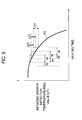
- FIG. 3 is a diagram showing a relationship between an increase in the infrared sensor output value and threshold value S 1 in the first exemplary embodiment of the present invention.
- FIG. 4 is a block diagram showing an induction heating cooker according to a second exemplary embodiment of the present invention.
- FIG. 5 is a block diagram of an induction heating cooker in the case where a cooking vessel is improperly placed according to a third exemplary embodiment of the present invention.
- FIG. 6 is a diagram showing a relationship between heating time and temperature of a side surface of the cooking vessel in the case where the cooking vessel is improperly placed and the case where the cooking vessel is properly placed in the third exemplary embodiment.
- FIG. 7 is a diagram showing a relationship between heating time and infrared sensor detection temperature in the case where the cooking vessel is improperly placed and the case where the cooking vessel is properly placed in a fourth exemplary embodiment of the present invention.
- FIG. 8 is a diagram showing a relationship between heating time and an increase in the infrared sensor detection temperature in the case where the cooking vessel is improperly placed in the fourth exemplary embodiment of the present invention.
- FIG. 9 is a diagram for describing a relationship between the infrared sensor detection temperature-rise value and heating time in the case where the cooking vessel is improperly placed in the fourth exemplary embodiment.
- FIG. 10 is a diagram for describing a relationship between an increase in the infrared sensor detection temperature-rise value and heating time in the case where the cooking vessel is improperly placed and the case where cooking vessel is properly placed in the fourth exemplary embodiment.
- an output value of an infrared sensor is described by using an output voltage value corresponding to infrared emissions detected by the infrared sensor and defining an increase in the output voltage value of the infrared sensor as an increase in the output value of the infrared sensor, or by using a detected temperature value of the infrared sensor, which is obtained by converting the output value of the infrared sensor into corresponding temperature, and a rise value in the detected temperature value of the infrared sensor.
- the both values do not deviate from the present invention. In this manner, the present invention is not limited to the following exemplary embodiments.
- FIG. 1 is a block diagram showing an induction heating cooker according to a first exemplary embodiment of the present invention.
- FIG. 2 is a diagram showing an increase in an infrared sensor output value, which is calculated from an output value of an infrared sensor that detects infrared emissions corresponding to temperature of a bottom surface of a cooking vessel when the cooking vessel is heated at a predetermined heating output by the induction heating cooker according to this embodiment.
- FIG. 3 is a diagram showing setting of a threshold value in determining the propriety of a pan placement position based on the increase in the infrared sensor output value in this embodiment.
- the induction heating cooker includes top plate 2 for carrying cooking vessel 1 placed thereon, heating coil 3 provided under top plate 2 and for inductively heating cooking vessel 1 , and inverter circuit 4 for supplying a high-frequency current to heating coil 3 .
- the induction heating cooker further includes infrared sensor 5 for detecting an infrared ray emitted from the bottom surface of cooking vessel 1 via sensor window 2 a formed on top plate 2 .
- Sensor window 2 a may be formed of another member differed from top plate 2 through which the infrared ray is transmitted.
- top plate 2 may be made of a ceramic material through which the infrared ray is transmitted, and a light-transmitting part of sensor window 2 a may be made of the same material as that of top plate 2 , and a back surface or a front surface of top plate 2 except for sensor window 2 a may be subjected to light-resistant printing and an unprinted part may form sensor window 2 a .
- infrared sensor 5 detects infrared emissions corresponding to temperature of the bottom surface of cooking vessel 1 .
- the induction heating cooker further includes heat-sensitive element 6 such as a thermistor in contact with a lower surface of top plate 2 to detect temperature of cooking vessel 1 and placement position determining part 8 for determining a placement position of cooking vessel 1 on top plate 2 .
- the induction heating cooker further includes control part 7 that reduces or stops outputting of inverter circuit 4 when the temperature detected by the heat-sensitive element 6 is higher than a control temperature value.
- control part 7 controls the inverter circuit 4 to supply the high-frequency current to heating coil 3 .
- Heating of cooking vessel 1 is started.
- Control part 7 controls the high-frequency current supplied to heating coil 3 based on the output of the infrared sensor 5 , thereby controlling high-frequency power supplied to heating coil 3 to control heating amount.
- control part 7 calculates increase ⁇ V in the output value of infrared sensor 5 (hereinafter, referred to as merely increase ⁇ V in the output value).
- control part 7 sets the control temperature value for heat-sensitive element 6 to any one of three control temperature values including control temperature value S 1 (second control temperature value), control temperature value S 2 (first control temperature value) that is higher than control temperature value S 1 , and control temperature value S 3 (third control temperature value) that is higher than control temperature value S 1 .
- Control temperature value S 2 may be equal to control temperature value S 3 . That is, control part 7 performs control to change the control temperature value for heat-sensitive element 6 to any of a plurality of values according to calculated increase ⁇ V in the output value.
- control part 7 controls outputting of inverter circuit 4 or stops the heating operation.
- the induction heating cooker of this embodiment performs cooking in this manner as well as prevents abnormal overheating of the cooking vessel.
- line P 1 shows a relationship between time passage and the output value of infrared sensor 5 .
- control part 7 sets the control temperature value for heat-sensitive element 6 to control temperature value S 2 for predetermined time t 1 (second predetermined time, for example, 110 seconds).
- second predetermined time for example, 110 seconds.
- Control part 7 compares increase ⁇ V in the output value of infrared sensor 5 with threshold value TH 1 (first threshold value, for example, 0.6 V), sets the control temperature value for heat-sensitive element 6 to control temperature value S 1 when increase ⁇ V in the output value is smaller than predetermined threshold value TH 1 , and sets the control temperature value for heat-sensitive element 6 to control temperature value S 3 when increase ⁇ V in the output value is larger than threshold value TH 1 .
- first threshold value for example, 0.6 V
- control temperature value for heat-sensitive element 6 is set to control temperature value S 2 that is higher than control temperature value S 1 until predetermined time t 1 has passed since the start of heating, that is, cooking vessel 1 is heated for a sufficient time and increase ⁇ V in the output value of infrared sensor 5 , which is sufficiently larger than threshold value TH 1 , can be observed, an unstable heating state due to affects of cooking vessel 1 and top plate 2 that are hot in the heating initial stage can be avoided.
- control part 7 compares increase ⁇ V in the output value of infrared sensor 5 with threshold value TH 1 , sets the control temperature value for heat-sensitive element 6 to control temperature value S 3 that is higher than control temperature value S 1 when increase ⁇ V in the output value is larger than threshold value TH 1 .
- Control temperature value S 3 may be the same as control temperature value S 2 or may be different from control temperature value S 2 .
- control part 7 determines that cooking vessel 1 is improperly placed and changes the control temperature value for heat-sensitive element 6 from control temperature value S 2 to control temperature value S 1 that is lower than control temperature value S 2 . That is, when cooking vessel 1 is normally placed on top plate 2 , after a lapse of predetermined time t 1 , cooking vessel 1 is heated and increase ⁇ V in the output value becomes larger than threshold value TH 1 .
- control part 7 determines that cooking vessel 1 is improperly placed and changes the control temperature value for heat-sensitive element 6 from control temperature value S 2 to control temperature value S 1 .
- FIG. 3 shows relationships among variations in increases ⁇ V in the output value due to material and position of cooking vessel 1 and threshold value TH 1 in this embodiment.
- Line G 1 shows increase ⁇ V 1 in the output value (for example, 1.1 V corresponding to difference in detected temperature of 23° C.) in the case where cooking vessel 1 having a high emissivity (for example, a black-coated iron pan having a thickness of 2 mm, the amount of oil stored in the vessel is 800 g) is placed at a normal position on top plate 2 and heated.
- Line G 2 shows increase ⁇ V 2 in the output value (for example, 0.8V corresponding to difference in detected temperature of 20° C.) in the case where cooking vessel 1 having a low emissivity (for example, a magnetic stainless pan having a thickness of 2 mm, the amount of oil stored in the vessel is 800 g) is placed at a normal position on top plate 2 and heated.
- Line E shows increase ⁇ V 3 in the output value in the case where infrared sensor 5 is broken, or cooking vessel 1 is not placed at the normal position on top plate 2 and is displaced from infrared sensor 5 .
- Line T shows first threshold value TH 1 (for example, 0.6V corresponding to difference in detected temperature of 12° C.).
- threshold value TH 1 is set to a value that is larger than increase ⁇ V 3 in the output value detected by infrared sensor 5 .
- threshold value TH 1 is set to a value that is smaller than increase ⁇ V 2 in the output value that can be detected by infrared sensor 5 after a lapse of predetermined time t 1 from the start of heating.
- Control temperature value S 1 is set to be temperature (for example, 100° C.) that is lower than temperature of the bottom surface of cooking vessel 1 , which is safe under heating for a long time.
- Control temperature value S 2 is set to be temperature (for example, 200° C. to 210° C.) that is higher than temperature of the bottom surface of cooking vessel 1 , which can be generally detected for control by infrared sensor 5 in the case of heating cooking vessel 1 having a high emissivity and is equal to or lower than temperature that can prevent oil-catching fire and the like.
- control temperature value for heat-sensitive element 6 can be set to relatively high control temperature value S 2 , thereby eliminating the unstable operation immediately after heating.
- control part 7 sets the control temperature value for heat-sensitive element 6 to control temperature value S 3 that is larger than control temperature value S 1 when increase ⁇ V in the output value of infrared sensor 5 is larger than threshold value TH 1 to control temperature according to the output of infrared sensor 5 .
- control temperature value S 3 is set to be temperature (for example, 200° C.
- control part 7 changes the control temperature value for heat-sensitive element 6 from control temperature value S 2 to control temperature value S 1 when increase ⁇ V in the output value detected by infrared sensor 5 is not more than threshold value TH 1 .
- control part 7 performs temperature control to prevent overheating.
- infrared sensor 5 does not normally function, for example, the position of cooking vessel 1 is displaced and increase ⁇ V in the output value is smaller than threshold value TH 1 , by lowering the control temperature value for heat-sensitive element 6 to control temperature value S 1 , the temperature of the bottom surface of cooking vessel 1 can be controlled to be low so that the heating operation can be continued more safely.
- the control temperature value may be set to control temperature value S 3 .
- the cooking vessel can be heated to target temperature according to control by infrared sensor 5 without turning on the power switch again, realizing the easy-to-use induction heating cooker. Even when increase ⁇ V in the output value becomes larger than threshold value TH 1 after the control temperature value of heat-sensitive element 6 is set to control temperature value S 1 , the control temperature value need not be changed to control temperature value S 2 . This is safer.
- control part 7 sets the control temperature value for heat-sensitive element 6 to control temperature value S 2 , and after a lapse of predetermined time t 1 from the start of heating, every after passage of predetermined time t 2 , control part 7 calculates increase ⁇ V in the output value of infrared sensor 5 for predetermined time t 3 that is smaller than predetermined time t 1 , changes the control temperature value to control temperature value S 1 that is smaller than control temperature value S 2 when increase ⁇ V in the output value is smaller than predetermined threshold value TH 1 , and sets the control temperature value to control temperature value S 3 which is higher than control temperature value S 1 when increase ⁇ V in the output value is larger than threshold value TH 1 .
- the temperature of heat-sensitive element 6 immediately after the start of heating unstably varies depending on material and thickness of cooking vessel 1 or temperature of cooking vessel 1 and top plate 2 at the start of heating.
- the control temperature value for heat-sensitive element 6 can be set to relatively high control temperature value S 2 that is not affected by temperature variation immediately after the start of heating.
- control temperature value S 1 when the control temperature value is set to control temperature value S 1 , even if the infrared sensor 5 does not normally work, for example, cooking vessel 1 is displaced from infrared sensor 5 during heating, the temperature of cooking vessel 1 can be maintained at predetermined temperature while preventing overheating.
- the control temperature value is set to control temperature value S 3 , as in the case where the control temperature value is set to control temperature value S 2 , overheating of unexpected cooking vessel 1 can be prevented.
- the temperature of the cooking vessel can be maintained low to continue heating while preventing overheating, and time required to achieve the target temperature can be reduced, thereby improving usability for the user.
- control part 7 may reduce the output of the inverter circuit 4 or stop the heating operation. Thereby, even when cooking vessel 1 is displaced from sensor window 2 a of infrared sensor 5 , safety can be similarly ensured.
- the placement position of cooking vessel 1 is determined except for during the initial unstable state at the start of heating. Furthermore, cooking vessel 1 storing much oil therein can be distinguished from cooking vessel 1 improperly placed. Therefore, it is possible to accurately detect that cooking vessel 1 is not properly placed on top plate 2 . In addition, it is easy for the user to use.
- FIG. 4 is a block diagram showing an induction heating cooker according to this embodiment.
- informing part 9 for issuing a warning is electrically connected to control part 7 .
- control part 7 determines that the placement position of cooking vessel 1 is improper and informing part 9 informs the fact. Thereby, it is possible to inform whether unexpected cooking vessel 1 is placed or heatable cooking vessel 1 is displaced from sensor window 2 a.
- Informing part 9 may inform that the temperature of cooking vessel 1 reaches control temperature value S 1 when the control temperature value is set to control temperature value S 1 and the temperature of cooking vessel 1 reaches control temperature value S 1 to reduce or stop outputting of inverter circuit 4 . Thereby, it is possible to inform whether unexpected cooking vessel 1 is placed or normal cooking vessel 1 is displaced from sensor window 2 a , resulting in that the heating output is reduced or heating is stopped.
- control part 7 informs the user that cooking vessel 1 is not properly placed. Thereby, the user can replace cooking vessel 1 at a proper position. For this reason, rapid proper heating can be achieved.
- the control temperature value can be changed to the control temperature value that is higher than control temperature value S 1 , for example, control temperature value S 2 or S 3 . In this case, usability is improved.
- the control temperature value S 1 is set so as not to be automatically changed even if the user replaces cooking vessel 1 at the proper position, the user stops heating once and restarts heating, thereby setting the control temperature value to control temperature value S 2 .
- informing part 9 for issuing the warning is further provided and when it is determined that cooking vessel 1 is not properly placed on top plate 2 after a lapse of predetermined time t 1 from the start of heating, control part 7 informs the fact through informing part 9 .
- Informing part 9 can obtain a similar effect by using a display device such as LED and LCD other than warning of buzzer sound, voice and the like.
- FIG. 5 is a block diagram of the induction heating cooker in the case where the cooking vessel is improperly placed in this embodiment.
- FIG. 6 is a diagram showing a relationship between heating time and temperature of a side surface of the cooking vessel in the case where the cooking vessel is properly placed and the case where the cooking vessel is improperly placed in this embodiment.
- placement position determining part 8 determines that the placement position of cooking vessel 1 is improper only when detected temperature T of infrared sensor 5 is higher than predetermined temperature value T 1 , in addition to the function of placement position determining part 8 in the first exemplary embodiment shown in FIG. 1 .
- the output voltage value corresponding to infrared emissions detected by infrared sensor 5 is used as the output value of infrared sensor 5
- an increase in the output voltage value of infrared sensor 5 is used as the increase in the output value of infrared sensor 5 .
- detected temperature T of infrared sensor 5 which is obtained by converting the output value of infrared sensor 5 into corresponding temperature
- rise value ⁇ T of the detected temperature value of the infrared sensor 5 are used for the explanation. That is, a vertical axis in FIG. 2 is reread as infrared sensor temperature T and increase ⁇ V is reread as rise value ⁇ T.
- control part 7 calculates rise value ⁇ T of detected temperature T of infrared sensor 5 for predetermined time t 3 (hereinafter, also referred to as temperature-rise value ⁇ T) every after passage of predetermined time t 2 . According to calculated temperature-rise value ⁇ T and detected temperature T of infrared sensor 5 , control part 7 detects that cooking vessel 1 is improperly placed on top plate 2 .
- placement position determining part 8 calculates temperature-rise value ⁇ T of detected temperature T for predetermined time t 3 every after passage of predetermined time t 2 , and determines that the placement position of cooking vessel 1 is improper when temperature-rise value ⁇ T is smaller than predetermined threshold value TH 1 (for example, 12° C.) for time that is longer than predetermined time t 4 (sixth predetermined time), and detected temperature T is larger than predetermined temperature value T 1 (for example, 210° C.).
- predetermined threshold value TH 1 for example, 12° C.
- predetermined temperature value T 1 for example, 210° C.
- infrared sensor 5 detects the temperature of the bottom surface of cooking vessel 1 .
- the temperature of the bottom surface of generally used cooking vessel 1 that stores oil of, for example, 800 g, as represented by broken line P 1 a in FIG. 6 , increases substantially linearly with a predetermined gradient.
- infrared sensor 5 detects temperature of the side surface of cooking vessel 1 in the vicinity of sensor window 2 a .
- the temperature of the side surface of cooking vessel 1 is, as represented by solid line P 2 in FIG. 6 , becomes characteristically saturated at a certain point.
- detected temperature T corresponding to infrared emissions detected by infrared sensor 5 is also proportional to the temperature of the side surface of cooking vessel 1 .
- temperature-rise value ⁇ T gradually decreases as it gets closer to the saturated state and finally becomes 0 (see below-mentioned solid line P 3 in FIG. 8 ).
- temperature-rise value ⁇ T of detected temperature T of infrared sensor 5 for predetermined time t 3 (for example, 1 minute) is calculated.
- temperature-rise value ⁇ T of detected temperature T is small in both of the case where the amount of oil is small and the case where cooking vessel 1 is not properly placed on top plate 2 , it is hard to distinguish the two cases from each other. However, there is a difference between the cases in detected temperature T.
- temperature-rise value ⁇ T of infrared sensor 5 is smaller than threshold value TH 1 for a time that is longer than predetermined time t 4 (for example, 5 seconds), that is, a calculation result of temperature-rise value ⁇ T of infrared sensor 5 is smaller than threshold value TH 1 consecutively a predetermined number of times or more (for example, five times or more), and detected temperature T of infrared sensor 5 is higher than predetermined temperature value T 1 (for example, 210° C.), placement position determining part 8 determines that placement position of cooking vessel 1 is improper.
- placement position determining part 8 can detect that cooking vessel 1 is not properly placed on top plate 2 , which is distinguished from the case where the amount of oil stored in cooking vessel 1 located at the proper placement position is large (for example, 3 liters or more).
- Predetermined temperature value T 1 may be set to be slightly higher than temperature that is generally used in cooking of deep-fried dish and not cause overheating.
- placement position determining part 8 does not determine that placement position of cooking vessel 1 is improper, and therefore, even when the amount of oil stored in cooking vessel 1 located at the proper placement position of is large, it is possible to prevent wrong determination that the placement position of cooking vessel 1 is improper.
- control temperature value for heat-sensitive element 6 is set to control temperature value S 1 that is lower than control temperature value S 2 . For this reason, heating can be continued while preventing overheating of cooking vessel 1 , thereby improving usability for the user.
- placement position determining part 8 determines that placement position of cooking vessel 1 is improper, as described above instead that the control temperature value for heat-sensitive element 6 is set to control temperature value S 1 that is lower than control temperature value S 2 , heating may be stopped or heating outputting may be reduced.
- This embodiment is especially effective in adjusting the temperature of oil in cooking of deep-fried dish, which requires highly accurate temperature adjustment.
- control part 7 calculates temperature-rise value ⁇ T of infrared sensor 5 for predetermined time t 3 every after passage of predetermined time t 2 and placement position determining part 8 determines that placement position of cooking vessel 1 is improper when temperature-rise value ⁇ T is smaller than predetermined time t 4 or predetermined threshold value TH 1 for a time that is longer than predetermined time t 4 and detected temperature T of infrared sensor 5 is larger than predetermined temperature value T 1 .
- placement position determining part 8 does not wrongly determine that cooking vessel 1 is not properly placed on top plate 2 .
- placement position determining part 8 can accurately detect that cooking vessel 1 is not properly placed on top plate 2 .
- control part 7 changes the control temperature value of heat-sensitive element 6 from control temperature value S 2 to control temperature value S 1 that is lower than control temperature value S 2 .
- FIG. 7 is a diagram showing a relationship between temperature value detected by infrared sensor 5 (hereinafter, also referred to as merely the detected temperature) and heating time in this embodiment.
- FIG. 8 and FIG. 9 are enlarged diagram showing a change in temperature gradient in the vicinity of a bending point of line P 4 a (scope represented by A) in FIG. 7 .
- FIG. 8 and FIG. 9 are diagrams each showing a relationship between temperature-rise value ⁇ T of the detected temperature of the infrared sensor for predetermined time t 3 (hereinafter, also referred to as merely the temperature-rise value ⁇ T) and heating time in this embodiment.
- FIG. 8 and FIG. 9 are diagrams each showing a relationship between temperature-rise value ⁇ T of the detected temperature of the infrared sensor for predetermined time t 3 (hereinafter, also referred to as merely the temperature-rise value ⁇ T) and heating time in this embodiment.
- FIG. 10 is a diagram showing a relationship between increase ⁇ 2 T in temperature-rise value ⁇ T of the detected temperature of the infrared sensor for predetermined time t 6 (fifth predetermined time) and heating time in this embodiment.
- the same constituents as those in the third exemplary embodiment are given the same reference numerals and description thereof is omitted, and only a difference between the fourth exemplary embodiment and the third exemplary embodiment will be described.
- placement position determining part 8 first calculates temperature-rise value ⁇ T of infrared sensor 5 for predetermined time t 3 every after passage of predetermined time t 2 , and calculates increase ⁇ 2 T in temperature-rise value ⁇ T of infrared sensor 5 for predetermined time t 6 every after passage of predetermined time t 5 .
- placement position determining part 8 determines that placement position of cooking vessel 1 is improper when temperature-rise value ⁇ T of infrared sensor 5 is less than threshold value TH 1 for predetermined time t 4 or longer, detected temperature T of infrared sensor 5 is larger than predetermined temperature value T 1 , and a calculated value of increase ⁇ 2 T in temperature-rise value ⁇ T of infrared sensor 5 is less than threshold value TH 2 as a negative value (second threshold value, TH 2 ⁇ 0) for predetermined time t 7 (ninth predetermined time) or longer.
- line P 4 shows the case where cooking vessel 1 storing a standard amount of oil (for example, 800 g. the same hereinafter) therein is properly placed on top plate 2 .
- a standard amount of oil for example, 800 g. the same hereinafter
- the detected temperature of the infrared sensor which corresponds to the output value of infrared sensor 5
- Line P 4 a shows the case where cooking vessel 1 is improperly placed on top plate 2 .
- the detected temperature of the side surface of the cooking vessel 1 increases with passage of the heating time and becomes saturated at a predetermined saturation temperature. Accordingly, temperature-rise value ⁇ T of infrared sensor 5 decreases as the heating time increases.
- Line P 4 b shows the case where the content in cooking vessel 1 is large (for example, 3 liters). That is, in the case where a large amount of oil is stored in cooking vessel 1 , even when cooking vessel 1 is properly placed, it takes time to increase the temperature. For this reason, also when the content in cooking vessel 1 is large, the temperature value of infrared sensor 5 increases with passage of time with a substantially constant gradient that is smaller than the gradient in line P 4 .
- FIG. 8 is a diagram showing a relationship between temperature-rise value ⁇ T of infrared sensor 5 and heating time in the case where cooking vessel 1 storing a standard amount of oil therein is properly placed, the case where cooking vessel 1 is improperly placed, and the case where cooking vessel 1 storing a large amount of oil therein is properly placed.
- line P 5 shows the case where cooking vessel 1 storing a standard amount of oil therein is properly placed.
- temperature-rise value ⁇ T of infrared sensor 5 is larger as compared to the case where the cooking vessel 1 storing a large amount of oil therein is properly placed, and is substantially constant.
- Line P 5 a shows the case where cooking vessel 1 is improperly placed.
- temperature-rise value ⁇ T of infrared sensor 5 rapidly decreases from a certain point and becomes saturated.
- Line P 5 b shows the case where a large amount of oil is stored in cooking vessel 1 .
- temperature-rise value ⁇ T of infrared sensor 5 is smaller than that of line P 4 and is substantially constant.
- temperature-rise value ⁇ T of infrared sensor 5 is small. For this reason, it is difficult to distinguish this case from the case where cooking vessel 1 is improperly placed merely by detecting temperature-rise value ⁇ T of infrared sensor 5 .
- temperature-rise value ⁇ T of infrared sensor 5 in the case where the content is large is close to temperature-rise value ⁇ T in the saturated state of infrared sensor 5 in the case where cooking vessel 1 is improperly placed, temperature-rise value ⁇ T of infrared sensor 5 is less than threshold value TH 1 for predetermined time t 4 and therefore, it is difficult to distinguish both from each other.
- temperature-rise value ⁇ T of infrared sensor 5 is small and therefore, it is difficult to distinguish this case from the case where cooking vessel 1 is improperly placed. For this reason, in this embodiment, first, as shown in FIG. 9 , there is calculated increase ⁇ 2 T in temperature-rise value ⁇ T of infrared sensor 5 for predetermined time t 6 (for example, 30 seconds) every after passage of predetermined time t 5 (for example, 1 second).
- FIG. 10 is a diagram showing a relationship between increase ⁇ 2 T in temperature-rise value ⁇ T of infrared sensor 5 and heating time in the case where cooking vessel 1 storing a standard amount of oil is properly placed, cooking vessel 1 is improperly placed, and the case where cooking vessel 1 storing a large amount of oil therein is properly placed.
- line P 6 shows the case where cooking vessel 1 storing a standard amount of oil therein is properly placed.
- increase ⁇ 2 T in temperature-rise value ⁇ T of infrared sensor 5 is about 0 and constant.
- Line P 6 a shows the case where cooking vessel 1 is improperly placed. In this case, as apparent from line P 5 a in FIG.
- temperature-rise value ⁇ T of infrared sensor 5 gradually decreases, while increase ⁇ 2 T in temperature-rise value ⁇ T of infrared sensor 5 is negative and its absolute value gradually increases, then, becomes smaller again and converges to 0.
- Line P 6 b shows the case where the content in cooking vessel 1 is large. In this case, as apparent from line P 5 b in FIG. 8 , like line P 6 b , increase ⁇ 2 T in temperature-rise value ⁇ T of infrared sensor 5 is about 0 and constant.
- control part 7 sets the control temperature value for heat-sensitive element 6 to control temperature value S 1 that is lower than control temperature value S 2 . That is, when increase ⁇ 2 T in temperature-rise value ⁇ T, which is a negative value having a large absolute value less than negative threshold value TH 2 , continues for some time, this case can be distinguished from the case where increase ⁇ 2 T in temperature-rise value ⁇ T that hardly changes and cooking vessel 1 storing a large amount of oil therein is located at a proper position. Thereby, as compared to configuration in the third exemplary embodiment, configuration in this embodiment can distinguish the case where cooking vessel 1 is improperly placed from the case where cooking vessel 1 having large content is improperly placed with higher accuracy. Consequently, since heating can be achieved without wrongly determining even the case where the content in cooking vessel 1 is large as the case where cooking vessel 1 is improperly placed, usability for the user can be improved.
- placement position determining part 8 can determine whether the placement position of cooking vessel 1 is improper or proper, and similar effect can be achieved.
- control part 7 calculates temperature-rise ⁇ T of infrared sensor 5 for predetermined time t 3 every after passage of predetermined time t 2 , and calculates increase ⁇ 2 T in temperature-rise value ⁇ T of infrared sensor 5 for predetermined time t 6 every after passage of predetermined time t 5 when temperature-rise ⁇ T of infrared sensor 5 is smaller than threshold value TH 1 for a time that is longer than predetermined time t 4 and detected temperature T of infrared sensor 5 is larger than predetermined temperature value T 1 , and placement position determining part 8 determines that placement position of cooking vessel 1 is improper when an absolute value of increase ⁇ 2 T in temperature-rise value ⁇ T is smaller than threshold value TH 2 for a time that is longer than predetermined time t 7 .
- control part 7 lowers the control temperature value for heat-sensitive element 6
- a fifth exemplary embodiment of the present invention will be described.
- the same constituents as those in the third exemplary embodiment are given the same reference numerals and description thereof is omitted, and only a difference between the fifth exemplary embodiment and the third exemplary embodiment will be described.
- the difference between this embodiment and the third exemplary embodiment is that placement position determining part 8 measures temperature-rise value ⁇ TS from detected temperature T of infrared sensor 5 at the start of heating, and when the state where temperature-rise value ⁇ TS is larger than predetermined value DT (first predetermined value) continues for predetermined time t 8 (seventh predetermined time) or longer, even before a lapse of predetermined time t 1 from the start of heating, starts determination of the placement position of cooking vessel 1 .
- infrared sensor 5 Since the output of infrared sensor 5 is not stable immediately after the start of heating due external disturbance and the like, temperature-rise value ⁇ T of infrared sensor 5 cannot be properly calculated after the start of heating. Accordingly, in the first to fourth exemplary embodiments, after a lapse of predetermined time t 1 from the start of heating, placement position determining part 8 performs the placement position determining operation.
- this embodiment has the configuration described in the first to fourth exemplary embodiments, following operations are performed.
- predetermined value DT for example, 20° C.
- predetermined time t 8 for example, 5 seconds
- placement position determining part 8 determines placement position of cooking vessel 1 when the state where temperature-rise value ⁇ TS from detected temperature T of infrared sensor 5 at the start of heating is larger than predetermined value DT continues for predetermined time t 8 or longer.
- placement position determining part 8 performs the placement position determining operation when temperature-rise value ⁇ TS from the detected temperature of the infrared sensor 5 at the start of heating is larger than predetermined value DT before a lapse of predetermined time t 1 from the start of heating.
- placement position determining part 8 may perform the placement position determining operation when increase in the output voltage of infrared sensor 5 from the start of heating is larger than predetermined value DV (second predetermined value, for example, output voltage corresponding to 20° C.) before a lapse of predetermined time t 1 from the start of heating.
- predetermined value DV second predetermined value, for example, output voltage corresponding to 20° C.
- placement position determining part 8 may perform the placement position determining operation when the state where the increase in the output voltage of infrared sensor 5 from the start of heating is larger than predetermined value DV continues for predetermined time t 9 (eighth predetermined time) or longer.
- heat-sensitive element 6 is not limited to the thermistor as long as it can achieve similar effects.
- placement position determining part 8 calculates the rising gradient of detected temperature T of infrared sensor 5 by calculating increase value ⁇ of the detected temperature of infrared sensor 5 for predetermined time t 3 that is smaller than predetermined time t 1 in each of the above-mentioned exemplary embodiments
- a method of calculating the rising gradient of the detected temperature of infrared sensor 5 is not limited to this.
- the rising gradient of detected temperature T of infrared sensor 5 with passage of time may be calculated by measuring time for detected temperature T of infrared sensor to reach a predetermined rise value.
- placement position determining part 8 calculates increase gradient ⁇ 2 T of rising gradient ⁇ T of detected temperature T of infrared sensor 5 with passage of time by calculating increase in the rising gradient for predetermined time t 6
- a method of calculating increase gradient ⁇ 2 T of rising gradient ⁇ T of the detected temperature of infrared sensor 5 is not limited to this. Since increase gradient ⁇ 2 T of rising gradient ⁇ T of the detected temperature of infrared sensor 5 with passage of time corresponds to a second derivative value of the detected temperature of infrared sensor 5 with respect to time, any method corresponding to this may be employed. For example, increase gradient ⁇ 2 T of rising gradient ⁇ T of detected temperature of infrared sensor 5 with passage of time may be calculated by measuring time for the rising gradient of detected temperature T of infrared sensor 5 to reach a predetermined increase.
- Configuration of each of the exemplary embodiments may be implemented in combination as appropriate.
- the present invention includes the top plate for carrying the cooking vessel placed thereon, the heating coil provided under the top plate and for inductively heating the cooking vessel, the inverter circuit for supplying the high-frequency current to the heating coil, the infrared sensor for detecting the infrared ray emitted from the bottom surface of the cooking vessel, the control part for reducing the output of the inverter circuit or stopping the heating operation when the detected temperature of the infrared sensor is higher than the control temperature value for the infrared sensor, and the placement position determining part for performing the placement position determining operation of calculating the rising gradient of the output value of the infrared sensor every after passage of a first predetermined time and performing the placement position determining operation for determining that the placement position of the cooking vessel is improper when the rising gradient is smaller than the first threshold value, and the placement position determining part performs the placement position determining operation after a lapse of the second predetermined time from the start of heating.
- the temperature of the cooking vessel can be controlled by use of the infrared sensor with high response, and wrong detection of the infrared sensor can be prevented. Further, even if the cooking vessel is displaced from the infrared sensor during heating, any slight displacement can be determined accurately to prevent overheating of the cooking vessel, which is excellent in usability.
- the induction heating cooker according to the present invention can properly heat the cooking vessel by use of the infrared sensor while preventing overheating of the cooking vessel, the induction heating cooker is useful as household or commercial induction heating cookers for inductively heating the cooking vessel and performing temperature control.
Landscapes
- Physics & Mathematics (AREA)
- Electromagnetism (AREA)
- Induction Heating Cooking Devices (AREA)
Applications Claiming Priority (5)
| Application Number | Priority Date | Filing Date | Title |
|---|---|---|---|
| JP2009067422 | 2009-03-19 | ||
| JP2009-067422 | 2009-03-19 | ||
| JP2009142885 | 2009-06-16 | ||
| JP2009-142885 | 2009-06-16 | ||
| PCT/JP2010/001730 WO2010106765A1 (ja) | 2009-03-19 | 2010-03-11 | 誘導加熱調理器 |
Publications (2)
| Publication Number | Publication Date |
|---|---|
| US20120000904A1 US20120000904A1 (en) | 2012-01-05 |
| US9769883B2 true US9769883B2 (en) | 2017-09-19 |
Family
ID=42739432
Family Applications (1)
| Application Number | Title | Priority Date | Filing Date |
|---|---|---|---|
| US13/256,154 Expired - Fee Related US9769883B2 (en) | 2009-03-19 | 2010-03-11 | Induction heating cooker |
Country Status (6)
| Country | Link |
|---|---|
| US (1) | US9769883B2 (es) |
| EP (1) | EP2410814B1 (es) |
| JP (1) | JP5655777B2 (es) |
| CN (1) | CN102356694B (es) |
| ES (1) | ES2560525T3 (es) |
| WO (1) | WO2010106765A1 (es) |
Cited By (3)
| Publication number | Priority date | Publication date | Assignee | Title |
|---|---|---|---|---|
| US10788220B2 (en) | 2018-07-13 | 2020-09-29 | Haier Us Appliance Solutions, Inc. | Determining cookware location on a cooktop appliance based on temperature response |
| USD1000206S1 (en) | 2021-03-05 | 2023-10-03 | Tramontina Teec S.A. | Cooktop or portion thereof |
| USD1000205S1 (en) | 2021-03-05 | 2023-10-03 | Tramontina Teec S.A. | Cooktop or portion thereof |
Families Citing this family (16)
| Publication number | Priority date | Publication date | Assignee | Title |
|---|---|---|---|---|
| US8598497B2 (en) | 2010-11-30 | 2013-12-03 | Bose Corporation | Cooking temperature and power control |
| US9006622B2 (en) | 2010-11-30 | 2015-04-14 | Bose Corporation | Induction cooking |
| CN102711301B (zh) * | 2011-03-28 | 2015-07-08 | 株式会社东芝 | 感应加热烹调器 |
| US9568369B2 (en) * | 2011-11-11 | 2017-02-14 | Turbochef Technologies, Inc. | IR temperature sensor for induction heating of food items |
| KR101981671B1 (ko) | 2012-07-27 | 2019-05-24 | 삼성전자주식회사 | 유도가열조리기 및 그 제어방법 |
| US9470423B2 (en) | 2013-12-02 | 2016-10-18 | Bose Corporation | Cooktop power control system |
| JP6106612B2 (ja) * | 2014-01-22 | 2017-04-05 | 日立アプライアンス株式会社 | 誘導加熱調理器 |
| US20150373787A1 (en) * | 2014-06-23 | 2015-12-24 | Cooktek Induction Systems, Llc | Apparatus and method for dual mode temperature sensing |
| EP3758443B1 (en) * | 2014-11-07 | 2023-06-07 | Breville PTY Limited | Cooktop |
| GB2537086B8 (en) * | 2014-12-02 | 2017-09-27 | King Abdulaziz Univ Faculty Of Computing & Information Tech | An energy efficient electric cooker |
| JP6560158B2 (ja) * | 2016-05-30 | 2019-08-14 | 株式会社松井製作所 | 金型温度調節装置及び金型温度調節方法 |
| US10356853B2 (en) | 2016-08-29 | 2019-07-16 | Cooktek Induction Systems, Llc | Infrared temperature sensing in induction cooking systems |
| CN108696955B (zh) * | 2017-04-10 | 2021-10-26 | 佛山市顺德区美的电热电器制造有限公司 | 用于电烹饪器的锅具干烧判断方法、装置和电烹饪器 |
| CN109699098B (zh) * | 2017-10-24 | 2021-08-20 | 佛山市顺德区美的电热电器制造有限公司 | 电磁加热烹饪器具及其锅具偏移检测方法和装置 |
| CN108388151A (zh) * | 2017-10-24 | 2018-08-10 | 广东亿龙电器科技有限公司 | 烹调设备控制方法、装置、计算机设备及存储介质 |
| JP7228778B2 (ja) * | 2018-09-25 | 2023-02-27 | パナソニックIpマネジメント株式会社 | 誘導加熱調理器 |
Citations (15)
| Publication number | Priority date | Publication date | Assignee | Title |
|---|---|---|---|---|
| JPH03184295A (ja) | 1989-12-14 | 1991-08-12 | Matsushita Electric Ind Co Ltd | 誘導加熱調理器 |
| DE4341485A1 (de) | 1993-12-06 | 1995-06-08 | Bosch Siemens Hausgeraete | Steuerung für Haushaltgeräte zur Auswertung von Sensorsignalen |
| US6140617A (en) | 1999-10-22 | 2000-10-31 | General Electric Company | Cooktop control and monitoring system including detecting properties of a utensil through a solid-surface cooktop |
| JP2003051377A (ja) | 2001-08-08 | 2003-02-21 | Matsushita Electric Ind Co Ltd | 誘導加熱調理器 |
| US6630650B2 (en) * | 2000-08-18 | 2003-10-07 | Luxine, Inc. | Induction heating and control system and method with high reliability and advanced performance features |
| CN1701639A (zh) | 2004-01-27 | 2005-11-23 | 松下电器产业株式会社 | 感应加热烹调器 |
| JP2005347000A (ja) | 2004-06-01 | 2005-12-15 | Matsushita Electric Ind Co Ltd | 誘導加熱調理器 |
| US20070080158A1 (en) * | 2003-11-25 | 2007-04-12 | Kabushiki Kaisha Toshiba | Heat cooking apparatus, cooking tool and heat cooking system |
| WO2007091440A1 (ja) * | 2006-02-07 | 2007-08-16 | Matsushita Electric Industrial Co., Ltd. | 誘導加熱装置 |
| WO2008000526A1 (en) | 2006-06-27 | 2008-01-03 | Siemens Aktiengesellschaft | Tool and method for erecting a tower segment |
| WO2008003872A2 (fr) | 2006-07-06 | 2008-01-10 | Seb Sa | Plaque de cuisson permettant la détection de la température d'un article culinaire |
| JP2008140678A (ja) | 2006-12-04 | 2008-06-19 | Matsushita Electric Ind Co Ltd | 加熱調理器 |
| JP2008192581A (ja) | 2007-02-08 | 2008-08-21 | Matsushita Electric Ind Co Ltd | 誘導加熱調理器 |
| WO2008120447A1 (ja) | 2007-03-12 | 2008-10-09 | Panasonic Corporation | 誘導加熱調理器 |
| CA2678840A1 (en) | 2007-08-13 | 2009-02-19 | Panasonic Corporation | Induction heating cooker |
Family Cites Families (1)
| Publication number | Priority date | Publication date | Assignee | Title |
|---|---|---|---|---|
| JP2008120447A (ja) | 2006-11-16 | 2008-05-29 | Mitsubishi Electric Corp | 梱包用緩衝材、およびこれを用いた梱包具 |
-
2010
- 2010-03-11 WO PCT/JP2010/001730 patent/WO2010106765A1/ja active Application Filing
- 2010-03-11 US US13/256,154 patent/US9769883B2/en not_active Expired - Fee Related
- 2010-03-11 EP EP10753262.4A patent/EP2410814B1/en not_active Not-in-force
- 2010-03-11 JP JP2011504737A patent/JP5655777B2/ja active Active
- 2010-03-11 CN CN201080012568.5A patent/CN102356694B/zh not_active Expired - Fee Related
- 2010-03-11 ES ES10753262.4T patent/ES2560525T3/es active Active
Patent Citations (20)
| Publication number | Priority date | Publication date | Assignee | Title |
|---|---|---|---|---|
| JPH03184295A (ja) | 1989-12-14 | 1991-08-12 | Matsushita Electric Ind Co Ltd | 誘導加熱調理器 |
| DE4341485A1 (de) | 1993-12-06 | 1995-06-08 | Bosch Siemens Hausgeraete | Steuerung für Haushaltgeräte zur Auswertung von Sensorsignalen |
| US6140617A (en) | 1999-10-22 | 2000-10-31 | General Electric Company | Cooktop control and monitoring system including detecting properties of a utensil through a solid-surface cooktop |
| US6630650B2 (en) * | 2000-08-18 | 2003-10-07 | Luxine, Inc. | Induction heating and control system and method with high reliability and advanced performance features |
| JP2003051377A (ja) | 2001-08-08 | 2003-02-21 | Matsushita Electric Ind Co Ltd | 誘導加熱調理器 |
| US20070080158A1 (en) * | 2003-11-25 | 2007-04-12 | Kabushiki Kaisha Toshiba | Heat cooking apparatus, cooking tool and heat cooking system |
| CN1701639A (zh) | 2004-01-27 | 2005-11-23 | 松下电器产业株式会社 | 感应加热烹调器 |
| US7102109B2 (en) * | 2004-01-27 | 2006-09-05 | Matsushita Electric Industrial Co., Ltd. | Induction cooking heater |
| JP2005347000A (ja) | 2004-06-01 | 2005-12-15 | Matsushita Electric Ind Co Ltd | 誘導加熱調理器 |
| EP1983804A1 (en) * | 2006-02-07 | 2008-10-22 | Matsushita Electric Industrial Co., Ltd. | Induction heating device |
| WO2007091440A1 (ja) * | 2006-02-07 | 2007-08-16 | Matsushita Electric Industrial Co., Ltd. | 誘導加熱装置 |
| WO2008000526A1 (en) | 2006-06-27 | 2008-01-03 | Siemens Aktiengesellschaft | Tool and method for erecting a tower segment |
| WO2008003872A2 (fr) | 2006-07-06 | 2008-01-10 | Seb Sa | Plaque de cuisson permettant la détection de la température d'un article culinaire |
| US20090314769A1 (en) | 2006-07-06 | 2009-12-24 | Seb S.A. | Hob allowing the temperature of a culinary article to be detected |
| JP2008140678A (ja) | 2006-12-04 | 2008-06-19 | Matsushita Electric Ind Co Ltd | 加熱調理器 |
| JP2008192581A (ja) | 2007-02-08 | 2008-08-21 | Matsushita Electric Ind Co Ltd | 誘導加熱調理器 |
| WO2008120447A1 (ja) | 2007-03-12 | 2008-10-09 | Panasonic Corporation | 誘導加熱調理器 |
| US20100051608A1 (en) | 2007-03-12 | 2010-03-04 | Hiroshi Tominaga | Induction cooking device |
| US20100065551A1 (en) | 2007-03-12 | 2010-03-18 | Hiroshi Tominaga | Induction cooking device |
| CA2678840A1 (en) | 2007-08-13 | 2009-02-19 | Panasonic Corporation | Induction heating cooker |
Non-Patent Citations (4)
| Title |
|---|
| Extended Search Report for corresponding European application serial No. 10753262.4, dated Jul. 16, 2014, 6 pages. |
| International Search Report for International Application No. PCT/JP2010/001730, dated Jun. 15, 2010, 2 pages. |
| Translation of JP 03-184295A to Fukishima dated Dec. 14, 1989. * |
| Translation of JP 2003-051377A to Noguchi dated Feb. 21, 2003. * |
Cited By (3)
| Publication number | Priority date | Publication date | Assignee | Title |
|---|---|---|---|---|
| US10788220B2 (en) | 2018-07-13 | 2020-09-29 | Haier Us Appliance Solutions, Inc. | Determining cookware location on a cooktop appliance based on temperature response |
| USD1000206S1 (en) | 2021-03-05 | 2023-10-03 | Tramontina Teec S.A. | Cooktop or portion thereof |
| USD1000205S1 (en) | 2021-03-05 | 2023-10-03 | Tramontina Teec S.A. | Cooktop or portion thereof |
Also Published As
| Publication number | Publication date |
|---|---|
| JP5655777B2 (ja) | 2015-01-21 |
| CN102356694A (zh) | 2012-02-15 |
| ES2560525T3 (es) | 2016-02-19 |
| JPWO2010106765A1 (ja) | 2012-09-20 |
| EP2410814A4 (en) | 2014-08-13 |
| WO2010106765A1 (ja) | 2010-09-23 |
| EP2410814B1 (en) | 2015-12-02 |
| EP2410814A1 (en) | 2012-01-25 |
| US20120000904A1 (en) | 2012-01-05 |
| CN102356694B (zh) | 2014-05-14 |
Similar Documents
| Publication | Publication Date | Title |
|---|---|---|
| US9769883B2 (en) | Induction heating cooker | |
| US8334487B2 (en) | Induction heating cooking device | |
| US20160076775A1 (en) | Device and method for cooktop fire mitigation | |
| US20120037614A1 (en) | Induction heating cooker | |
| JPH04356619A (ja) | 調理器 | |
| JP2008140678A (ja) | 加熱調理器 | |
| JP4393799B2 (ja) | 誘導加熱調理器 | |
| JP2011165346A (ja) | 誘導加熱調理器 | |
| JP2000283472A (ja) | 加熱調理器 | |
| KR20130122265A (ko) | 조리용기의 열전도율에 따른 과열방지장치 및 방법 | |
| KR101710457B1 (ko) | 조리기 | |
| KR101622612B1 (ko) | 라면조리시간 설정기능을 구비한 가스레인지용 라면조리장치 | |
| KR101183930B1 (ko) | 전기 레인지 안전 차단 제어 방법 | |
| JP5579101B2 (ja) | 誘導加熱調理器 | |
| MXPA00011872A (es) | Metodo y dispositivo para detectar sobrecalentamientos de un recipiente colocado en una planca para cocinar de ceramica de vidrio durante la preparacion de alimentos. | |
| JP3563238B2 (ja) | 加熱調理器 | |
| JP4087342B2 (ja) | 電磁調理器 | |
| JP4241298B2 (ja) | 誘導加熱調理器 | |
| JP2009134918A (ja) | 加熱調理器 | |
| EP1699332B1 (en) | Method and control arrangement for terminating accidental switch on of a deep fryer apparatus not filled with oil | |
| SE536689C2 (sv) | Anordning som förhindrar spisbrand och tillåter att normal matlagning kan fortgå | |
| JP2009059565A (ja) | 誘導加熱調理器 | |
| JP2000297932A (ja) | 加熱調理器 | |
| JP2000283466A (ja) | 過熱防止用安全装置付きコンロ及びその制御方法 | |
| KR0154636B1 (ko) | 기계식 전자렌지의 자동조리 제어장치 |
Legal Events
| Date | Code | Title | Description |
|---|---|---|---|
| AS | Assignment |
Owner name: PANASONIC CORPORATION, JAPAN Free format text: ASSIGNMENT OF ASSIGNORS INTEREST;ASSIGNORS:HASHIMOTO, TAKUYA;WATANABE, KENJI;NOGUCHI, SHINTARO;AND OTHERS;SIGNING DATES FROM 20110805 TO 20110808;REEL/FRAME:027213/0043 |
|
| AS | Assignment |
Owner name: PANASONIC INTELLECTUAL PROPERTY MANAGEMENT CO., LTD., JAPAN Free format text: ASSIGNMENT OF ASSIGNORS INTEREST;ASSIGNOR:PANASONIC CORPORATION;REEL/FRAME:034194/0143 Effective date: 20141110 Owner name: PANASONIC INTELLECTUAL PROPERTY MANAGEMENT CO., LT Free format text: ASSIGNMENT OF ASSIGNORS INTEREST;ASSIGNOR:PANASONIC CORPORATION;REEL/FRAME:034194/0143 Effective date: 20141110 |
|
| STCF | Information on status: patent grant |
Free format text: PATENTED CASE |
|
| AS | Assignment |
Owner name: PANASONIC INTELLECTUAL PROPERTY MANAGEMENT CO., LTD., JAPAN Free format text: CORRECTIVE ASSIGNMENT TO CORRECT THE ERRONEOUSLY FILED APPLICATION NUMBERS 13/384239, 13/498734, 14/116681 AND 14/301144 PREVIOUSLY RECORDED ON REEL 034194 FRAME 0143. ASSIGNOR(S) HEREBY CONFIRMS THE ASSIGNMENT;ASSIGNOR:PANASONIC CORPORATION;REEL/FRAME:056788/0362 Effective date: 20141110 |
|
| FEPP | Fee payment procedure |
Free format text: MAINTENANCE FEE REMINDER MAILED (ORIGINAL EVENT CODE: REM.); ENTITY STATUS OF PATENT OWNER: LARGE ENTITY |
|
| LAPS | Lapse for failure to pay maintenance fees |
Free format text: PATENT EXPIRED FOR FAILURE TO PAY MAINTENANCE FEES (ORIGINAL EVENT CODE: EXP.); ENTITY STATUS OF PATENT OWNER: LARGE ENTITY |
|
| STCH | Information on status: patent discontinuation |
Free format text: PATENT EXPIRED DUE TO NONPAYMENT OF MAINTENANCE FEES UNDER 37 CFR 1.362 |
|
| FP | Lapsed due to failure to pay maintenance fee |
Effective date: 20210919 |