US9517498B2 - Aluminum impact extruded bottle with threaded neck made from recycled aluminum and enhanced alloys - Google Patents
Aluminum impact extruded bottle with threaded neck made from recycled aluminum and enhanced alloys Download PDFInfo
- Publication number
- US9517498B2 US9517498B2 US14/246,728 US201414246728A US9517498B2 US 9517498 B2 US9517498 B2 US 9517498B2 US 201414246728 A US201414246728 A US 201414246728A US 9517498 B2 US9517498 B2 US 9517498B2
- Authority
- US
- United States
- Prior art keywords
- metallic bottle
- aluminum
- inches
- aluminum alloy
- approximately
- Prior art date
- Legal status (The legal status is an assumption and is not a legal conclusion. Google has not performed a legal analysis and makes no representation as to the accuracy of the status listed.)
- Active, expires
Links
Images


Classifications
-
- B—PERFORMING OPERATIONS; TRANSPORTING
- B21—MECHANICAL METAL-WORKING WITHOUT ESSENTIALLY REMOVING MATERIAL; PUNCHING METAL
- B21C—MANUFACTURE OF METAL SHEETS, WIRE, RODS, TUBES, PROFILES OR LIKE SEMI-MANUFACTURED PRODUCTS OTHERWISE THAN BY ROLLING; AUXILIARY OPERATIONS USED IN CONNECTION WITH METAL-WORKING WITHOUT ESSENTIALLY REMOVING MATERIAL
- B21C23/00—Extruding metal; Impact extrusion
- B21C23/002—Extruding materials of special alloys so far as the composition of the alloy requires or permits special extruding methods of sequences
-
- B—PERFORMING OPERATIONS; TRANSPORTING
- B21—MECHANICAL METAL-WORKING WITHOUT ESSENTIALLY REMOVING MATERIAL; PUNCHING METAL
- B21C—MANUFACTURE OF METAL SHEETS, WIRE, RODS, TUBES, PROFILES OR LIKE SEMI-MANUFACTURED PRODUCTS OTHERWISE THAN BY ROLLING; AUXILIARY OPERATIONS USED IN CONNECTION WITH METAL-WORKING WITHOUT ESSENTIALLY REMOVING MATERIAL
- B21C23/00—Extruding metal; Impact extrusion
- B21C23/02—Making uncoated products
- B21C23/18—Making uncoated products by impact extrusion
- B21C23/186—Making uncoated products by impact extrusion by backward extrusion
-
- B—PERFORMING OPERATIONS; TRANSPORTING
- B21—MECHANICAL METAL-WORKING WITHOUT ESSENTIALLY REMOVING MATERIAL; PUNCHING METAL
- B21D—WORKING OR PROCESSING OF SHEET METAL OR METAL TUBES, RODS OR PROFILES WITHOUT ESSENTIALLY REMOVING MATERIAL; PUNCHING METAL
- B21D51/00—Making hollow objects
- B21D51/16—Making hollow objects characterised by the use of the objects
- B21D51/26—Making hollow objects characterised by the use of the objects cans or tins; Closing same in a permanent manner
- B21D51/2615—Edge treatment of cans or tins
-
- B—PERFORMING OPERATIONS; TRANSPORTING
- B65—CONVEYING; PACKING; STORING; HANDLING THIN OR FILAMENTARY MATERIAL
- B65D—CONTAINERS FOR STORAGE OR TRANSPORT OF ARTICLES OR MATERIALS, e.g. BAGS, BARRELS, BOTTLES, BOXES, CANS, CARTONS, CRATES, DRUMS, JARS, TANKS, HOPPERS, FORWARDING CONTAINERS; ACCESSORIES, CLOSURES, OR FITTINGS THEREFOR; PACKAGING ELEMENTS; PACKAGES
- B65D1/00—Rigid or semi-rigid containers having bodies formed in one piece, e.g. by casting metallic material, by moulding plastics, by blowing vitreous material, by throwing ceramic material, by moulding pulped fibrous material or by deep-drawing operations performed on sheet material
- B65D1/02—Bottles or similar containers with necks or like restricted apertures, designed for pouring contents
- B65D1/0207—Bottles or similar containers with necks or like restricted apertures, designed for pouring contents characterised by material, e.g. composition, physical features
-
- B—PERFORMING OPERATIONS; TRANSPORTING
- B65—CONVEYING; PACKING; STORING; HANDLING THIN OR FILAMENTARY MATERIAL
- B65D—CONTAINERS FOR STORAGE OR TRANSPORT OF ARTICLES OR MATERIALS, e.g. BAGS, BARRELS, BOTTLES, BOXES, CANS, CARTONS, CRATES, DRUMS, JARS, TANKS, HOPPERS, FORWARDING CONTAINERS; ACCESSORIES, CLOSURES, OR FITTINGS THEREFOR; PACKAGING ELEMENTS; PACKAGES
- B65D1/00—Rigid or semi-rigid containers having bodies formed in one piece, e.g. by casting metallic material, by moulding plastics, by blowing vitreous material, by throwing ceramic material, by moulding pulped fibrous material or by deep-drawing operations performed on sheet material
- B65D1/02—Bottles or similar containers with necks or like restricted apertures, designed for pouring contents
- B65D1/0223—Bottles or similar containers with necks or like restricted apertures, designed for pouring contents characterised by shape
- B65D1/023—Neck construction
- B65D1/0246—Closure retaining means, e.g. beads, screw-threads
-
- B—PERFORMING OPERATIONS; TRANSPORTING
- B65—CONVEYING; PACKING; STORING; HANDLING THIN OR FILAMENTARY MATERIAL
- B65D—CONTAINERS FOR STORAGE OR TRANSPORT OF ARTICLES OR MATERIALS, e.g. BAGS, BARRELS, BOTTLES, BOXES, CANS, CARTONS, CRATES, DRUMS, JARS, TANKS, HOPPERS, FORWARDING CONTAINERS; ACCESSORIES, CLOSURES, OR FITTINGS THEREFOR; PACKAGING ELEMENTS; PACKAGES
- B65D41/00—Caps, e.g. crown caps or crown seals, i.e. members having parts arranged for engagement with the external periphery of a neck or wall defining a pouring opening or discharge aperture; Protective cap-like covers for closure members, e.g. decorative covers of metal foil or paper
- B65D41/02—Caps or cap-like covers without lines of weakness, tearing strips, tags, or like opening or removal devices
- B65D41/04—Threaded or like caps or cap-like covers secured by rotation
- B65D41/0435—Threaded or like caps or cap-like covers secured by rotation with separate sealing elements
- B65D41/045—Discs
-
- B—PERFORMING OPERATIONS; TRANSPORTING
- B65—CONVEYING; PACKING; STORING; HANDLING THIN OR FILAMENTARY MATERIAL
- B65D—CONTAINERS FOR STORAGE OR TRANSPORT OF ARTICLES OR MATERIALS, e.g. BAGS, BARRELS, BOTTLES, BOXES, CANS, CARTONS, CRATES, DRUMS, JARS, TANKS, HOPPERS, FORWARDING CONTAINERS; ACCESSORIES, CLOSURES, OR FITTINGS THEREFOR; PACKAGING ELEMENTS; PACKAGES
- B65D41/00—Caps, e.g. crown caps or crown seals, i.e. members having parts arranged for engagement with the external periphery of a neck or wall defining a pouring opening or discharge aperture; Protective cap-like covers for closure members, e.g. decorative covers of metal foil or paper
- B65D41/02—Caps or cap-like covers without lines of weakness, tearing strips, tags, or like opening or removal devices
- B65D41/04—Threaded or like caps or cap-like covers secured by rotation
- B65D41/0435—Threaded or like caps or cap-like covers secured by rotation with separate sealing elements
- B65D41/0464—Threaded or like caps or cap-like covers secured by rotation with separate sealing elements the screw-thread or the like being formed by conforming the cap-skirt to the thread or the like formation on a container neck
-
- C—CHEMISTRY; METALLURGY
- C22—METALLURGY; FERROUS OR NON-FERROUS ALLOYS; TREATMENT OF ALLOYS OR NON-FERROUS METALS
- C22C—ALLOYS
- C22C1/00—Making non-ferrous alloys
-
- C—CHEMISTRY; METALLURGY
- C22—METALLURGY; FERROUS OR NON-FERROUS ALLOYS; TREATMENT OF ALLOYS OR NON-FERROUS METALS
- C22C—ALLOYS
- C22C21/00—Alloys based on aluminium
-
- B—PERFORMING OPERATIONS; TRANSPORTING
- B21—MECHANICAL METAL-WORKING WITHOUT ESSENTIALLY REMOVING MATERIAL; PUNCHING METAL
- B21C—MANUFACTURE OF METAL SHEETS, WIRE, RODS, TUBES, PROFILES OR LIKE SEMI-MANUFACTURED PRODUCTS OTHERWISE THAN BY ROLLING; AUXILIARY OPERATIONS USED IN CONNECTION WITH METAL-WORKING WITHOUT ESSENTIALLY REMOVING MATERIAL
- B21C23/00—Extruding metal; Impact extrusion
- B21C23/02—Making uncoated products
- B21C23/18—Making uncoated products by impact extrusion
-
- B—PERFORMING OPERATIONS; TRANSPORTING
- B21—MECHANICAL METAL-WORKING WITHOUT ESSENTIALLY REMOVING MATERIAL; PUNCHING METAL
- B21H—MAKING PARTICULAR METAL OBJECTS BY ROLLING, e.g. SCREWS, WHEELS, RINGS, BARRELS, BALLS
- B21H3/00—Making helical bodies or bodies having parts of helical shape
- B21H3/02—Making helical bodies or bodies having parts of helical shape external screw-threads ; Making dies for thread rolling
- B21H3/04—Making by means of profiled-rolls or die rolls
-
- B—PERFORMING OPERATIONS; TRANSPORTING
- B23—MACHINE TOOLS; METAL-WORKING NOT OTHERWISE PROVIDED FOR
- B23P—METAL-WORKING NOT OTHERWISE PROVIDED FOR; COMBINED OPERATIONS; UNIVERSAL MACHINE TOOLS
- B23P15/00—Making specific metal objects by operations not covered by a single other subclass or a group in this subclass
-
- B—PERFORMING OPERATIONS; TRANSPORTING
- B65—CONVEYING; PACKING; STORING; HANDLING THIN OR FILAMENTARY MATERIAL
- B65D—CONTAINERS FOR STORAGE OR TRANSPORT OF ARTICLES OR MATERIALS, e.g. BAGS, BARRELS, BOTTLES, BOXES, CANS, CARTONS, CRATES, DRUMS, JARS, TANKS, HOPPERS, FORWARDING CONTAINERS; ACCESSORIES, CLOSURES, OR FITTINGS THEREFOR; PACKAGING ELEMENTS; PACKAGES
- B65D1/00—Rigid or semi-rigid containers having bodies formed in one piece, e.g. by casting metallic material, by moulding plastics, by blowing vitreous material, by throwing ceramic material, by moulding pulped fibrous material or by deep-drawing operations performed on sheet material
- B65D1/02—Bottles or similar containers with necks or like restricted apertures, designed for pouring contents
-
- C—CHEMISTRY; METALLURGY
- C22—METALLURGY; FERROUS OR NON-FERROUS ALLOYS; TREATMENT OF ALLOYS OR NON-FERROUS METALS
- C22C—ALLOYS
- C22C21/00—Alloys based on aluminium
- C22C21/02—Alloys based on aluminium with silicon as the next major constituent
-
- C—CHEMISTRY; METALLURGY
- C22—METALLURGY; FERROUS OR NON-FERROUS ALLOYS; TREATMENT OF ALLOYS OR NON-FERROUS METALS
- C22F—CHANGING THE PHYSICAL STRUCTURE OF NON-FERROUS METALS AND NON-FERROUS ALLOYS
- C22F1/00—Changing the physical structure of non-ferrous metals or alloys by heat treatment or by hot or cold working
- C22F1/04—Changing the physical structure of non-ferrous metals or alloys by heat treatment or by hot or cold working of aluminium or alloys based thereon
- C22F1/043—Changing the physical structure of non-ferrous metals or alloys by heat treatment or by hot or cold working of aluminium or alloys based thereon of alloys with silicon as the next major constituent
-
- Y—GENERAL TAGGING OF NEW TECHNOLOGICAL DEVELOPMENTS; GENERAL TAGGING OF CROSS-SECTIONAL TECHNOLOGIES SPANNING OVER SEVERAL SECTIONS OF THE IPC; TECHNICAL SUBJECTS COVERED BY FORMER USPC CROSS-REFERENCE ART COLLECTIONS [XRACs] AND DIGESTS
- Y10—TECHNICAL SUBJECTS COVERED BY FORMER USPC
- Y10T—TECHNICAL SUBJECTS COVERED BY FORMER US CLASSIFICATION
- Y10T29/00—Metal working
- Y10T29/49—Method of mechanical manufacture
- Y10T29/4998—Combined manufacture including applying or shaping of fluent material
- Y10T29/49988—Metal casting
- Y10T29/49989—Followed by cutting or removing material
Definitions
- the present invention relates generally to forming a threaded neck in a metallic bottle manufactured by a process known as impact extrusion. More specifically, the present invention relates to methods, apparatus and alloy compositions used in the impact extrusion manufacturing of containers and other articles with sufficient strength characteristics to allow threading of the container neck to receive threaded closures.
- Aluminum bottles offer the bottling industry and consumers many benefits. Aluminum bottles provide ideal surfaces to decorate with brand names, logos, designs, product information, and/or other preferred indicia and thus offer bottlers, distributors, and retailers an ability to stand out at the point of sale. Aluminum bottles have a strength-to-weight ratio advantage which enables higher stacking than comparable glass bottles. The increased durability of aluminum bottles also reduces the number of containers damaged during processing and shipping, resulting in further savings. Additionally, aluminum bottles are lighter than glass bottles resulting in energy savings during shipment. Finally, recycling aluminum bottles is easier because labels and other indicia are printed directly onto the aluminum bottles while glass and plastic bottles typically have labels that must be separated during the recycling process.
- Aluminum beverage bottles are particularly attractive to consumers because of the convenience they offer.
- the light weight of aluminum bottles makes them easier to carry.
- Aluminum bottles are particularly suitable for use in public places and outdoors because they are durable, safe, and give effective protection from light and air which may negatively affect the quality and taste of the beverage contained in the aluminum bottle.
- aluminum bottles cool down faster than beverage containers made of other materials resulting in colder beverages faster.
- Glass bottles do not offer the same convenience because they are heavier than aluminum bottles and are easier to break. Further, some public facilities and parks prohibit glass bottles because they pose a safety risk when broken.
- Aluminum beverage bottles are known in the container industry and may be formed using an impact extrusion process.
- Impact extrusion is a process utilized to make metallic containers and other articles with unique shapes.
- the products are typically made from a softened metal slug comprised of steel, magnesium, copper, aluminum, tin, and lead and other alloys.
- the container is formed inside a confining die from a cold slug which is contacted by a punch. The force from the punch deforms the metal slug around an outer diameter of the punch and the inner diameter of the confining die.
- the container or other apparatus is removed from the punch with a counter-punch ejector, and other necking and shaping tools are used to form the device to a preferred shape.
- the present invention contemplates the use of a higher strength aluminum alloy which may be used during an impact extrusion process to form containers with integral threaded necks having sufficient mechanical strength to close with a roll on pilfer proof (ROPP) closure.
- the aluminum alloy is comprised at least partly from a recycled scrap material such as aluminum beverage containers.
- the present invention allows for the use of IE containers with thinner walls than are possible with an IE container made from 1070 or 1050 aluminum alloy IE methods.
- IE container body with a high performance integral thread for capping pressurized beverage containers with a threaded closure it is possible to manufacture a lower cost, thin walled, IE aluminum container body with a high performance integral thread for capping pressurized beverage containers with a threaded closure.
- a container strong enough for threading is formed in an impact extrusion process using unique alloys specifically adapted for use in an IE process, said unique alloys blended from various scrap materials with other virgin metals.
- alloying elements such as but not limited to magnesium, may be added to the alloy to refine the chemical composition of the recycled aluminum alloy of the present invention.
- a novel alloy is provided in the initial form of a metal slug and used to form a metallic container in an impact extrusion process, wherein the metallic container is of sufficient strength to thread the neck.
- the alloy in one embodiment has a composition comprised of a recycled 3105 or 3104 aluminum, and a relatively pure 1070 aluminum to form a novel recycled alloy.
- a recycled aluminum alloy which utilizes 40% of 3104 alloy is blended with a 1070 alloy, and which comprises the following composition: approximately 98.47% aluminum; approximately 0.15% Si; approximately 0.31% Fe; approximately 0.09% Cu; approximately 0.41% Mn; approximately 0.49% Mg; approximately 0.05% Zn; approximately 0.02% Cr; and approximately 0.01% Ti.
- 60% to 80% of a recycled aluminum is blended with a 1070 alloy to form a recycled aluminum alloy.
- the recycled aluminum comprises approximately 0.26% Si; approximately 0.53% Fe; approximately 0.16% Cu; approximately 0.84% Mn; approximately 0.6% Mg; approximately 0.12% Zn; approximately 0.02% Cr; and approximately 0.02% Ti.
- the recycled aluminum alloy comprises between about 97.70% aluminum and about 98.05% aluminum; between about 0.16% Si and about 0.24% Si; between about 0.37% Fe and about 0.48% Fe; between about 0.08% Cu and about 0.15% Cu; between about 0.48% Mn and about 0.71% Mn; between about 0.34% Mg and about 0.52% Mg; between about 0.06% Zn and about 0.12% Zn; between about 0.01% Cr and about 0.04% Cr; and between about 0.00% Ti and about 0.04% Ti.
- the method generally comprises (1) forming a slug with an aluminum alloy; (2) deforming the slug into a preferred shape in an impact extrusion process to form the metallic bottle; and (3) forming threads on the neck portion of the metallic bottle, the threads adapted to receive a threaded closure which can be selectively opened and closed.
- the method may further comprise: (4) adding a titanium boride to the aluminum alloy; (5) forming individual slugs from a slab formed from a casting apparatus; (6) annealing the individual slugs in a continuous annealing process, and (7) finishing the slugs by shot blasting to increase the surface area of the slugs.
- the aluminum alloy in one embodiment is comprised of a scrap metal of at least one of a 3104, a 3004, a 3003, a 3103, a 3013 and a 3105 aluminum alloy blended with a relatively pure aluminum alloy. In one embodiment, the aluminum alloy is blended from approximately 60% of a scrap aluminum alloy and approximately 40% of a 1070 aluminum alloy, wherein the scrap aluminum alloy comprises: between about 0.20 wt.
- the scrap aluminum alloy comprises about 0.26% Si; about 0.53% Fe; about 0.16% Cu; about 0.84% Mn; about 0.60% Mg; about 0.12% Zn; about 0.02% Cr; and about 0.02% Ti.
- the aluminum alloy comprises between about 98.15% aluminum and about 98.50% aluminum; between about 0.16% Si and about 0.20% Si; between about 0.37% Fe and about 0.41% Fe; between about 0.08% Cu and about 0.12% Cu; between about 0.48% Mn and about 0.54% Mn; between about 0.34% Mg and about 0.40% Mg; between about 0.06% Zn and about 0.10% Zn; between about 0.01% Cr and about 0.04% Cr; and between about 0.00% Ti and about 0.04% Ti.
- the aluminum alloy consists of: about 98.33% aluminum; about 0.18% Si; about 0.39% Fe; about 0.10% Cu; about 0.51% Mn; about 0.37% Mg; about 0.08% Zn; about 0.02% Cr; and about 0.02% Ti.
- the threads have an exterior diameter of between approximately 1.4 inches and approximately 1.6 inches. In a preferred embodiment, the exterior diameter of the threads is between approximately 1.44 inches and approximately 1.54 inches. In another embodiment, the threads have an exterior diameter between approximately 1.2 inches and approximately 1.4 inches. In a preferred embodiment, the exterior diameter of the threads is between approximately 1.24 inches and approximately 1.34 inches. In yet another embodiment, the threads have an exterior diameter between approximately 1.0 inches and approximately 1.2 inches. In a preferred embodiment, the exterior diameter of the threads is between approximately 1.05 inches and approximately 1.15 inches. In still another embodiment, the exterior diameter of the threads is between approximately 1.0 inches and approximately 1.6 inches.
- the threads have a pitch, or distance from a crest of one thread to a crest of another thread, of between about 0.10 inches and about 0.15 inches. In another embodiment, the pitch is approximately 0.125 inches, or approximately eight threads per inch.
- a body portion of the metallic bottle has a thickness between about 0.0098 inches and about 0.0155 inches. In a more preferred embodiment, the bottle has a thickness between about 0.0135 inches to about 0.0145 inches.
- the metallic bottle has a diameter of between approximately 2.6 inches and approximately 2.85 inches. In a preferred embodiment, the diameter of the metallic bottle may be between 2.64 and 2.75 inches. In one embodiment, the metallic bottle has a height between approximately 6.2 inches and approximately 7.25 inches. In another embodiment, the metallic bottle has a height between about 6.2 inches and about 6.3 inches. In still another embodiment, the height of the metallic bottle is between about 7.1 inches and about 7.25 inches.
- the method includes, but is not limited to: (1) providing scrap aluminum material; (2) melting the scrap aluminum material with a 1070 aluminum alloy to form the recycled aluminum alloy, wherein the recycled aluminum alloy comprises: about 98.33% aluminum, about 0.18% Si, about 0.39% Fe, about 0.10% Cu, about 0.51% Mn, about 0.37% Mg, about 0.08% Zn, about 0.02% Cr, and about 0.02% Ti; (3) casting the recycled aluminum alloy into a slab; (4) rolling the slab to a specified thickness of between about 0.1181 inches to about 0.5512 inches; (5) cooling the slab to a predetermined temperature at an ambient temperature of between about 59° F.
- the slab is cooled for between about 4 hours to about 8 hours. In another embodiment, the slab is cooled for longer than 24 hours. In still another embodiment, the slab is cooled for longer than 1 week.
- Forming threads in the neck portion generally comprises positioning the metallic bottle in a chuck to support the metallic bottle and hold the metallic bottle in a predetermined position.
- An inner core piece of a thread forming device is positioned in the opening of the metallic bottle in contact with an interior surface portion of the neck of the metallic bottle.
- An outer core piece of the thread forming device is positioned in contact with an exterior surface of the neck of the metallic bottle.
- a compressive force is applied to the neck of the metallic bottle by thread forming surfaces of the inner core piece and the outer core piece.
- the thread forming surfaces of the inner and outer core pieces have concave and convex portions predetermined to form threads of a predetermined size and geometry on the metallic bottle.
- the thread forming device is rotated around an axial center of the metallic bottle so that the inner core piece and the outer core piece move around a circumference of the neck of the metallic bottle.
- the method may further comprise: (13) wall ironing the extruded tube to increase the thickness of at least a portion of the neck portion, wherein the thickness of the at least a portion of neck region is greater than a thickness of the body portion of the metallic bottle, and wherein the thickness of the at least a portion of the neck region is about 0.0125 inches and about 0.0155 inches; and (14) sealing the opening of the metallic bottle with a ROPP closure.
- the ROPP closure generally comprises a top portion, a generally cylindrical body portion extending downwardly from the top portion, a detachable pilfer band formed on a lowermost portion of the cylindrical body portion, an open aperture facing downward, and a liner in an interior top portion of the ROPP closure.
- the cylindrical body portion of the ROPP closure used to seal the opening of the metallic bottle is initially unthreaded.
- Sealing the metallic bottle generally comprises: placing the ROPP closure over the threads in the neck portion of the metallic bottle; pressing the ROPP closure downwardly onto sealing surfaces formed on the uppermost portion of the neck portion of the metallic bottle, compressing a liner of the ROPP closure between the sealing surfaces and the top portion of the ROPP closure; pressing a thread roller against an exterior surface of the cylindrical body portion of the ROPP closure, wherein the thread roller applies a compressive force to the cylindrical body portion and rotates around the ROPP closure to form threads in the cylindrical body portion; and pressing a pilfer roller against an exterior surface of the pilfer band to prevent the pilfer band from being removed from the neck portion of the metallic bottle when the ROPP closure is removed from the metallic bottle.
- Impact extruding the slug may comprise: placing the slug in a die having a conical shape; and impacting the slug with a steel punch having a predetermined shape, wherein the extruded tube is extruded backwards out of the die.
- the die has a Vickers hardness (HV) of between approximately 920 HV and approximately 1080 HV. In a more preferred embodiment, the die has a hardness of between approximately 970 HV and approximately 1030 HV. In a still more preferred embodiment, the die has a hardness of between approximately 990 HV and approximately 1010 HV. In one embodiment the punch has a hardness of between approximately 600 HV and approximately 760 HV.
- the punch has a hardness of between approximately 640 HV and approximately 720 HV. In a still more preferred embodiment, the punch has a hardness of between approximately 670 HV and approximately 690 HV. In one embodiment, the slug has a diameter of between approximately 1.61 inches and approximately 1.91 inches. In a more preferred embodiment, the slug has a diameter of between approximately 1.71 inches and approximately 1.81 inches. In a still more preferred embodiment, the slug has a diameter of between approximately 1.75 inches and approximately 1.766 inches. In one embodiment, the slug has a height of between about 0.17 inches and about 0.27 inches. In another embodiment, the slug has a height of between about 0.20 inches and about 0.235 inches.
- the slug has a height of between about 0.216 inches and about 0.217. In one embodiment, the slug has a mass of between approximately 0.69 ounces and approximately 0.875 ounces. In a more preferred embodiment, the slug has a mass of between approximately 0.7 ounces and approximately 0.865 ounces. In a still more preferred embodiment, the slug has a mass of between about 0.740 ounces and about 0.825 ounces.
- the aluminum alloy comprises: between about 97.70 wt. % aluminum and about 98.05 wt. % aluminum; between about 0.20 wt. % Si and about 0.24 wt. % Si; between about 0.44 wt. % Fe and about 0.48 wt. % Fe; between about 0.11 wt. % Cu and about 0.15 wt. % Cu; between about 0.65 wt. % Mn and about 0.71 wt. % Mn; between about 0.46 wt. % Mg and about 0.52 wt. % Mg; between about 0.08 wt. % Zn and about 0.12 wt. % Zn; between about 0.01 wt. % Cr and about 0.04 wt. % Cr; and between about 0.00 wt. % Ti and about 0.04 wt. % Ti.
- the threads are formed by a thread forming device, the thread forming device comprising: a chuck to hold the metallic bottle in a predetermined position; an inner core piece with a first thread forming surface operable to apply a force to an interior surface of the neck portion of the metallic bottle; and an outer core piece with a second thread forming surface operable to apply a force to an exterior surface of the neck portion of the metallic bottle, wherein the thread forming device is operable to rotate around an axial center of the metallic bottle.
- Still another aspect of the present invention is a metallic bottle with a threaded neck, the metallic bottle generally comprising: a bottom dome portion; a body portion extending upwardly from the bottom dome portion; a neck portion extending upwardly from the body portion; threads formed on an exterior surface of the neck portion; and an opening positioned on an uppermost portion of the neck portion. Sealing surfaces are formed on the uppermost portion of the metallic bottle and a pilfer band skirt is formed on the neck portion of the metallic bottle.
- the metallic bottle is comprised of a recycled aluminum alloy, the recycled aluminum alloy comprising: between about 97.70 wt. % aluminum and about 98.50 wt. % aluminum, between about 0.16 wt. % Si and about 0.24 wt. % Si, between about 0.37 wt. % Fe and about 0.48 wt. % Fe, between about 0.08 wt. % Cu and about 0.15 wt. % Cu, between about 0.48 wt. % Mn and about 0.71 wt. % Mn, between about 0.34 wt. % Mg and about 0.52 wt. % Mg, between about 0.06 wt. % Zn and about 0.12 wt.
- the threaded neck of the metallic bottle has a predetermined geometry adapted to receive a ROPP closure, the threads adapted to receive the ROPP closure having an interior diameter of about 1.5 inches. In another embodiment, the threads are adapted to receive the ROPP closure having an interior diameter of about 1.3 inches. In yet another embodiment, the threads are adapted to receive the ROPP closure having an interior diameter of about 1.1 inches. In one embodiment, the threads have a pitch of between about 0.10 inches and about 0.15 inches. In another embodiment, the pitch of the threads is approximately 0.125 inches, or approximately eight threads per inch.
- the metallic bottle has a body with a diameter of between approximately 2.537 inches and approximately 2.838 inches. In a more preferred embodiment, the body of the metallic has a diameter of between approximately 2.68 inches and approximately 2.695 inches. In one embodiment, the metallic bottle has a height of between approximately 6.0 inches and approximately 7.4 inches. In another embodiment, the metallic bottle has and a height of between approximately 6.175 inches and approximately 6.325 inches. In a preferred embodiment, the metallic bottle has and a height of between approximately 6.2 inches and approximately 6.3 inches. In still another embodiment, the metallic bottle has and a height of between approximately 7.112 inches and approximately 7.263 inches. In a preferred embodiment, the metallic bottle has and a height of between approximately 7.162 inches and approximately 7.213 inches.
- compositions of aluminum alloys are provided and contemplated herein.
- the amount of each component i.e., Si, Fe, Cu, etc. may be varied approximately 15% to achieve satisfactory results.
- at least one of Si, Fe, and Cu is added to the aluminum alloy.
- only one of Si, Fe, and Cu is added to the aluminum alloy.
- no Si, Fe, or Cu is added to the aluminum alloy.
- other elements may be added to the aluminum alloy.
- one or more of Mn, Zn, Cr, and Ti are added to the alloy aluminum.
- only one of Mn, Zn, Cr, and Ti are added to the aluminum alloy.
- novel alloy compositions described herein and used in the impact extrusion process be comprised entirely or in part with recycled components and alloys. Rather, the alloys may be obtained and blended from stock materials which have not previously been used or implemented in previous products or processes.
- lightweight containers with threaded necks comprising recycled contents are provided. At least one of the following advantages may be realized: strength to weight ratio; burst pressures; deformation pressures; dent resistance; resistance to scratching or galling; and/or reduction in weight and metal content. Other advantages are also contemplated. Furthermore, aspects and features of the present invention provide for containers with increased resistance to back annealing allowing liner materials with higher cure temperatures. In various embodiments, an alloy for producing IE containers with higher back annealing resistance is contemplated, resulting in improved container performance, and utilizing coatings requiring higher curing temperatures. Container designs and tooling designs for producing such containers are also contemplated.
- an aluminum slug and corresponding IE container with sufficient strength characteristics to thread the neck and comprising recycled material is provided.
- the recycled content may be post-industrial or post-consumer content, the use of which enhances overall product and process efficiency.
- a significant portion of known scrap, such as offal from cup making processes, contains a higher concentration of alloying elements than the base 1070 alloy currently used. These alloying elements, while providing various cost and environmental advantages, modify the metallurgical characteristics of the aluminum. For example, inclusion of these elements increases the solidification temperature range. Casting challenges are thus present. As yield strength increases and the ductility decreases, issues are created with respect to rolling the strip, for example.
- Recrystallization characteristics are known to change, necessitating potential changes to the thermomechanical treatment(s), including but not limited to: rolling temperatures, rolling reductions, annealing temperatures, annealing process, and/or annealing times.
- the increased ultimate tensile strength and yield strength increases the tonnage loads when punching slugs.
- Tonnage loads on the extrusion presses are typically higher in connection with slugs of the present invention.
- the increased material strength of the present invention enables attainment of standard container performance specifications at significant lower container weights and/or wall thicknesses.
- containers Although generally referred to herein as “containers,” “metal containers,” “metallic bottles,” “aluminum bottles,” and/or “bottles,” it should be appreciated that the processes and alloy compositions of the current invention may be used to form any variety of containers or other articles of manufacture of any size or shape. Accordingly, the term “metallic bottle” is intended to cover containers of any type.
- references made herein to “caps,” “closures,” “threaded closures,” “Roll on Pilfer Proof Closures,” and “ROPP closures” should not necessarily be construed as limiting the present invention to a particular type of closure or a particular thread design. It should be appreciated that the current process may be used to form a metal container with threads suitable for any variety of closures including ROPP closures, crown caps, and twist off caps of any size, thread design, or thread geometry. The current invention may also be used to form a metal container with interior threads designed to be sealed with a closure having threads formed on an exterior surface of the closure wherein the closure is inserted into an opening of the metal container.
- closures may be formed of any suitable material know in the art including metal, plastic, rubber, wood, cork, glass, or any combination thereof.
- each of the expressions “at least one of A, B and C,” “at least one of A, B, or C,” “one or more of A, B, and C,” “one or more of A, B, or C,” and “A, B, and/or C” means A alone, B alone, C alone, A and B together, A and C together, B and C together, or A, B and C together.
- FIG. 1 illustrates a method for manufacturing an alloy slug from a recycled aluminum material
- FIG. 2 illustrates an impact extrusion method for use with the recycled aluminum material, and is a continuation of the process shown in FIG. 1 ;
- FIG. 3 illustrates a continuous anneal process
- FIGS. 4A and 4B illustrate a method and the associated tools used to form threads on a metallic bottle according to one embodiment of the present invention
- FIG. 5A is a fragmented front elevation view of a threaded neck of a metallic bottle of one embodiment of the present invention
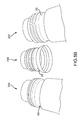
- FIG. 5B is a fragmented prospective view of threaded neck designs of metallic bottles manufactured by impact extrusion according to certain embodiments of the present invention.
- FIGS. 6A and 6B illustrate a method of sealing a metallic bottle with a closure according to one embodiment of the present invention
- FIG. 7 illustrates a method and the associated tools used to form threads on a ROPP closure according to one embodiment of the present invention
- FIG. 8 are front elevation views of sealed metallic bottles according to various embodiments of the present invention.
- FIG. 9 illustrates an alloy composition and comparison of Material 1 and Material 2
- FIG. 10 illustrates a punch head and press die used in various embodiments of the present invention
- FIG. 11 illustrates deformation pressure resistance for containers made with Material 1 and Material 2;
- FIG. 12 illustrates burst pressure resistance for Material 1 and Material 2
- FIG. 13 illustrates container mass for sample Material 1 and sample Material 2.
- various aluminum alloys are identified by numerical indications such as 1070 or 3104.
- aluminum is designated by its major corresponding alloying elements, typically in four-digit arrangement. The first of these four numbers corresponds to a group of aluminum alloys sharing a major alloying element, such as 2XXX (or copper, 3XXX for manganese, 4XXX (for silicon, etc.
- major alloying element such as 2XXX (or copper, 3XXX for manganese, 4XXX (for silicon, etc.
- the term “recycled aluminum alloy” (which may be abbreviate “RA”) followed by a number may be used to identify a particular alloy of the present invention.
- the term “recycled aluminum alloy” or “RE” is merely an identifier for a metal containing recycled aluminum.
- 3104 aluminum alloy commonly known in the art is recycled with another material, typically 1070 aluminum alloy. The number and percentage used after the term “recycled aluminum” identifies the percent of that 3104 recycled alloy which is combined with a 1070 aluminum alloy to form the new alloy used in an impact extrusion process.
- recycled aluminum alloy 3104 30% or RA 3104-30 identifies that 30% of a 3104 alloy has been combined with 70% of a relatively pure 1070 aluminum alloy to form a new alloy having the metallurgical composition of Si, Fe, Cu, etc. provided in the charts.
- Other charts refer to the number “3105” and a percentage of that alloy provided in a given alloy, such as 20% or 40%.
- the term “3105” is an aluminum alloy well known by those skilled in the art, and the 20% or 40% reflects the amount of that alloy which is mixed with a relatively pure 1070 aluminum alloy to form the new alloy which is used in the metal slug and the impact extrusion process to manufacture a container such as an aerosol can.
- Table 2 illustrates compositions of recycled slug materials, wherein the pure aluminum is aluminum alloy 1070 and the recycled scrap material is 3104 at different percentages. All values listed in the table are approximate values.
- Table 3 illustrates compositions of recycled slug materials, wherein the pure aluminum is aluminum alloy 1070 and the recycled scrap material is alloy 3105 at different percentages. All values listed in the table are approximate values.
- Table 4 illustrates compositions of recycled slug materials, wherein the pure aluminum is aluminum alloy 1070 and the recycled scrap material is alloy 3004 at different percentages. All values listed in the table are approximate values.
- Table 5 illustrates compositions of recycled slug materials, wherein aluminum alloy 1070 is combined with a recycled aluminum material with the composition indicated.
- the recycled aluminum material represents an alloy formed from various scrap aluminum material. All values listed in the table are approximate values.
- FIG. 1 illustrates a method 100 of fabricating an alloy from recycled aluminum. While a general order of method 100 is illustrated in FIG. 1 , the method 100 can include more or fewer steps and the order of the steps can be arranged differently than the method 100 illustrated in FIG. 1 .
- the recycled aluminum is processed to make slugs, which may be used in an impact extrusion process. Following the formation of the slugs, the slugs are processed in order to manufacture a metallic bottle as provided in FIG. 2 , which is discussed in greater detail below.
- the recycled aluminum slug material may comprise a recycled scrap aluminum and a pure aluminum, which are melted and cast together to form a novel recycled aluminum slug.
- Suitable recycled aluminum material may include many 3XXX alloys, especially 3005, 3104, 3105, 3103, 3013, and 3003 alloys. In smaller quantities, other alloys may be used to achieve the target chemistry. Alloy 3104 scrap is commonly sourced from beverage can plants. Alloy 3005 is commonly sourced from the automotive industry.
- the pure aluminum may include aluminum alloys 1070 or 1050. A variety of scrap aluminum sources may be used as a source for the alloying element of the recycled aluminum alloy of the present invention. Pure aluminum alloys such as 1050 or 1070 may be used with elemental additions to achieve the target chemical composition of the recycled aluminum alloy.
- Scraps bricks comprising recycled scrap aluminum are melted to facilitate mixing with the molten pure aluminum 102 .
- the recycled scrap aluminum may comprise aluminum alloys 3005, 3104, 3105, 3003, 3013, or 3103.
- the furnace flame directly contacts the recycled aluminum, a small amount of the surface aluminum oxidizes. If the surface area is large, such as compacted scrap bricks, the amount of the material oxidized and the melt loss is higher than if the scrap bricks comprise a small surface area. Therefore, melting furnaces that utilize indirect methods to heat the materials are preferred to those that utilize direct flame impingement.
- melting may occur in several types of furnaces.
- a reverbatory furnace 112 may be used which is typical to produce conventional impact extrusion slugs.
- the aluminum is subject to direct flame impingement.
- a reverbatory furnace 112 is not a preferred method to produce recycled aluminum alloy slugs because of the high melt loss.
- a furnace that utilizes an indirect method to heat the materials is preferred.
- Furnaces that utilize an indirect method to heat materials include, but are not limited to, side well furnaces 110 and rotary furnaces 104 .
- a side well furnace 110 may be used as the furnace.
- Side well furnaces contain the aluminum and gas burners transfer heat to the molten metal. The molten metal is then used to melt the scrap.
- Side well furnaces also have an impeller that circulates the molten bath through a side well.
- Scrap aluminum is fed into the side well at a rate such that the material largely melts before it circulates into the portion of the side well furnace where direct flame impingement is possible.
- the use of a side well furnace 110 is a preferred method for melting scrap metal for the recycled aluminum alloy production.
- a rotary furnace 104 may be used.
- a rotary furnace 104 is similar to a concrete mixer. The aluminum scrap tumbles in one corner of the rotating cylinder. The flame is directed away from this area and heats the refractory lining. The hot lining rotates and contacts the aluminum and transfers energy to the aluminum.
- a rotary furnace 104 is a preferred method for melting scrap for the production of the recycled aluminum alloy. If a rotary furnace 104 or side well furnace 110 is used, the scrap exiting the rotary furnace 104 or side well furnace 110 may be melted and cast into ingots, sows or pigs 106 in an operation separated from the slug production. These ingots, sows or pigs may be melted in a second reverbatory furnace 108 with minimal melt loss because the surface area is relatively small. If elevated melt loss does occur during the melting process, dross must be removed from the bath.
- Titanium boride (TiBor) 114 is added to the melted blend of aluminum alloys just prior to the caster normally by a continuous feed of aluminum with a titanium boride dispersion.
- the TiBor could possibly be added to the aluminum scrap alloy while it is in the furnace.
- the TiBor may refine the grain structure of the recycled aluminum alloy during processing.
- the TiBor concentration is between about 1 lb/ton to about 2.6 lb/ton. In some embodiments, the TiBor concentration is about 0.6 kg/metric tonne.
- the molten alloy is cast.
- molten alloy is solidified into a continuous slab of any suitable dimension using one of several casting techniques.
- the cast slabs are about 8 inches to about 14 inches in width and about 0.75 inches to about 1.5 inches thick.
- the casting speed should be in the range of between about 0.55 to about 0.88 tons/hour/inch of width. In some embodiments, the casting speed may be about 0.68 tons/hour/inch of width.
- Different casting methods may be used and may be chosen from a Hazelett caster 116 , a wheel belt caster 118 , a twin roll caster 120 and/or a block caster 122 .
- a wheel belt caster 118 When a wheel belt caster 118 is used, the molten aluminum is held between a flanged wheel and a thick metal belt during solidification. The belt wraps around the wheel at about 180°. Both the wheel and the belt are chilled with water on the back side to optimize and control heat extraction.
- This wheel belt caster process is commonly used to make 1070 and 1050 slugs.
- the thick steel belt is inflexible and unable to deflect and maintain contact with the slab that is shrinking due to solidification. The effect is magnified by the recycled aluminum alloys because it solidifies over a larger temperature range than the more pure alloys, 1050 and 1070.
- a Hazelett caster 116 may be used.
- the molten aluminum is held between two parallel, flexible steel belts during solidification.
- Steel dam blocks are chain mounted and form the sides of the mold.
- the parallel belts slope slightly downward to allow gravity to feed molten aluminum into the system.
- High pressure water is sprayed on the back side of both belts to optimize and control heat extraction. This high pressure water also deflects the belt to keep it in contact with the solidifying, contracting slab. This belt deflection enables the Hazelett caster 116 to produce a wide range of aluminum (and other) alloys.
- the Hazelett caster process is commonly used to produce architectural aluminum strip and may be used to produce impact extrusion slugs.
- a twin roll caster 120 may be used.
- the molten aluminum is held between two counter rotating, water cooled rolls during solidification.
- the process provides a very small solidification zone and is therefore limited to relatively thin “slabs.” At this thickness, the term strip is probably more accurate than slab. This process is commonly used in the manufacture of aluminum foil.
- a block caster 122 may be used.
- the molten aluminum is held between a series of chain mounted steel blocks during solidification that form the sides of the mold.
- the blocks are water cooled to optimize and control heat extraction.
- a lubricating powder may be applied to the caster components that contact the slab. More specifically, a graphite or silica powder may be applied as necessary. Temperature control is important during and following the casting process. During casting, regardless of the casting process used, the cooling rate and temperature profile of the slab must be carefully controlled during solidification. The wheel belt caster 118 reduces the cooling water flow rate to achieve this. If the Hazelett caster 116 is used, the water flow for general control and gas flow over the slab may be used to closely modify the temperature. Ambient conditions, especially air flow must be controlled near the caster. This air flow control is especially critical when gas flow is used to modify the slab temperature.
- the temperature of the slab at the exit of the caster must also be carefully controlled.
- the exit temperature of the slab through the caster must be above about 968° F., however the maximum temperature of any part of the slab exiting the caster must be less than about 1080° F.
- the thickness of the slab is reduced from about 1.10-1.38 inches to a specified thickness of between about 0.118 inches to about 0.551 inches with a hot mill 124 / 126 and a cold mill 130 / 132 .
- the relative thickness reduction taken in the hot mill 124 / 126 and the cold mill 130 / 132 significantly affects the metallurgical grain structure of the finished product.
- the thickness of the slab at the hot mill exit may vary. In some embodiments, the thickness of the slab following hot milling 124 / 126 is between about 0.236 inches to about 0.709 inches. In order to reach the specified thickness, the slab passes between two counter rotating rolls with a gap less than the incoming thickness while the slab is still at a high temperature of between about 842° F.
- Rolling mills have two commonly used configurations. The most common is a two-high mill that contains only two counter-rotating rolls that contact the slab/strip. Two rolling mills are used to obtain the desired thickness. However, a different number of rolling mills may be used: 1, 3, etc.
- an advanced design is a four-high mill in which the two-counter rotating rolls, the work rolls, are backed up by larger rolls.
- an additional hot mill 126 may be used. Alternatively, multiple hot mills may be used and the slabs may be recirculated to a hot mill 124 / 126 in order to achieve the specified thickness.
- the alloy material may dynamically recrystallize and/or recover.
- This recrystallization and/or recovery is a self annealing process enabled by the heat in the slab/strip.
- the temperatures at which dynamic recrystallization and/or recovery may occur varies with alloy content and may therefore differ for 1050/1070 and recycled aluminum alloys. In most instances, the temperature for dynamic recrystallization and/or recovery is between about 662° F. to about 1,022° F. for recycled aluminum alloy material.
- the hot rolled strip is immersed in a quench tank 128 .
- the quench tank 128 contains water that reduces the strip temperature to near ambient.
- the strip is subjected to a cold mill 130 / 132 .
- the strip may be at ambient temperature and passes between two counter rotating rolls with a gap less than the incoming thickness. Normally two rolling mills may be used to obtain the desired thickness. However, a different number of rolling mills may be used: 1, 3, etc.
- the cold rolled strip does not recrystallize. This cold working causes the yield strength of the material to increase and the ductility decreases.
- Cold mills 130 / 132 may have two-high and four-high configurations.
- the four-high configuration may have better thickness control and is therefore strongly preferred during cold rolling when the final thickness is made.
- an additional cold mill 132 may be used.
- multiple cold mills may be used and the slabs may be recirculated to a cold mill 130 / 132 in order to achieve the specified thickness.
- the relative amounts of thickness reduction taken during the hot mill 124 / 126 and cold mill 130 / 132 have a large effect on the recovery and recrystallization kinetics during annealing.
- the optimal ratio varies with alloy content, rolling mill capability and final strip thickness.
- strips may be subjected to ambient cooling 134 at between about 59° F. to about 122° F., preferably about 77° F., for between about 4 hours to about 8 hours following cold milling 130 / 132 .
- the cooled strip is typically held in storage to allow it to return to ambient temperature.
- the cooled strips are punched 136 .
- the cooled strip is uncoiled and fed into a die set mounted in a press.
- the die set cuts circular slugs from the strip, though it is understood that any shape of slug such as triangle, oval, circle, square, diamond, rectangle, pentagon, or the like may be used depending upon the shape of the die and/or the desired end product.
- the punching tool may be modified in order to control burrs.
- the tool may be modified so that the die button chamfer is between about 0.039 inches by about 25° to about 0.050 inches by 29°.
- the punched slugs are heated to recrystallize the grains and ideally form a homogeneous, equiaxed grain structure.
- the process decreases the strength of the material and increases ductility.
- Annealing may occur by batch annealing 138 and/or continuous annealing 140 .
- the punched slugs When the punched slugs are batch annealed 138 , the punched slugs may be loosely loaded into a holding device such as a wire mesh baskets.
- a holding device such as a wire mesh baskets.
- Several holding devices may be stacked together inside a furnace. The door to the furnace is closed and the slugs may be heated to a target temperature and held for a specified time.
- the target temperature within the interior of furnace is preferably between about 878° F. to about 1,112° F. for between about 5 to about 9 hours, though the annealing time and temperature have a strong interaction and are influenced by the alloy content of the slugs.
- the furnace may be turned off and the slugs allowed to slowly cool in the furnace.
- the punched slugs may be continuously annealed 140 .
- the slugs are loosely distributed on a metal mesh belt on conveyed through a multi-zone furnace.
- the punched slugs are quickly heated to a peak metal temperature and then quickly cooled.
- the operation may be performed in air.
- the peak metal temperature of the punched slugs is between about 842° F. to about 1058° F.
- the peak metal temperature influences the final metallurgical characteristics.
- the peak temperature for optimal metallurgical characteristics is influenced by alloy content.
- Continuous annealing 140 is the preferred process for producing recycled aluminum alloy slugs. Continuous annealing 140 provides two benefits over batch annealing.
- the shorter time at elevated temperature reduces oxide formation on the surface of the slug.
- Aluminum oxides are a concern, however, magnesium oxides are a major concern due to its extreme abrasive nature. Increased magnesium oxide on the surface of the punched slugs may cause excessive scratching of tools used during the impact extrusion process. On extended runs these scratches are an unacceptable quality defect.
- the precisely controlled and homogeneous thermal cycle including rapid heating, limited time at elevated temperature, and rapid cooling of the continuous anneal 140 results in improved and more uniform metallurgical grain structure. This in turn produces IE containers of higher strength. Higher strength containers enable the IE containers to be lighter.
- FIG. 3 illustrates temperature curves of a continuous annealing process.
- the surface of the punched slugs may be finished by roughening the surface of the punched slugs.
- Different methods may be used to finish the punched slugs.
- a tumbler process 142 may be used. A large quantity of the punched slugs are placed in a drum or other container and the drum is rotated and/or vibrated. As slugs fall onto other slugs, denting may occur to one or both slugs.
- the purpose of roughening the surface is to increase the high surface area of the punched slug and create recesses to hold lubricant.
- the large faces of the punched slugs may also be finished along with the sheared surfaces.
- a shot blast finishing process 144 may be used.
- the shot blast finishing process 144 a large number of slugs are placed in an enclosed drum and subjected to impingement by aluminum shot or other materials. The shot forms small depression on the surfaces of the slugs. The slugs are tumbled slightly so the aluminum shot contacts all surfaces of the slug.
- Shot blasting 144 is the preferred process for producing recycled aluminum alloy slugs, and aggressive shot blasting has been shown to be the most effective at removing surface oxides from slugs. This removal of the surface oxides are especially critical for removing adherent magnesium oxides, which cause scratches in IE containers if they are not removed from the slug.
- FIG. 2 illustrates a method 200 of manufacturing a metallic bottle 250 using a slug manufactured from recycled scrap material according to the method 100 as illustrated in FIG. 1 . While a general order of method 200 is illustrated in FIG. 2 , the method 200 can include more or fewer steps and the order of the steps can be arranged differently than illustrated in FIG. 2 .
- One embodiment of a metallic bottle 250 of the present invention is illustrated in FIG. 4A .
- a slug lubrication process 202 may be used wherein the slugs are tumbled with a powdered lubricant. Any suitable lubricant may be used as appreciated by one skilled in the art. Typically about 3.53 oz of lubricant is used per about 220 lb of slugs. Tumbling the lubricant with the slugs forces lubricant onto the slugs. If the slugs have been roughened, then tumbling the slugs with the lubricants forces the lubricant into the depressions created during the finishing operation.
- the lubricated slugs are subjected to an impact extrusion process 204 . More specifically, the lubricated slugs are placed in a cemented carbide die of precise shape. The lubricated slug is impacted by a steel punch, also of precise shape, and the aluminum is extruded backwards away from the die.
- the tooling shapes dictate the wall thickness of the extruded tube portion of the metallic bottle 250 . Although this process is generally known as back extrusion, a forward extrusion process or combinations of back and forward extrusion could also be used as appreciated by one skilled in the art.
- the tooling of the punch and die have shapes to form threads in the extruded metallic bottle 250 .
- wall ironing 206 may be performed.
- the metallic bottle 250 may be passed between a punch and an ironing die with negative clearance.
- wall ironing 206 thins the wall of the tube.
- wall ironing 206 is performed on the tube to increase the thickness of an area that will become the thread region 266 of the neck portion 258 of the metallic bottle 250 to between about 0.0125 inches and about 0.0155 inches.
- the thickness of the thread region 266 is greater than a thickness of the body portion 252 of the metallic bottle 250 , resulting in a stronger thread region 266 without increasing the amount of used to form the rest of the metallic bottle 250 and thereby reducing the material cost of each metallic bottle produced.
- the higher strength of the recycled aluminum alloy increases die deflection. Therefore a smaller die is required to achieve the desired wall thickness. This optional process optimizes material distribution and keeps longer tubes straight.
- the dome forming 208 on the bottom 254 of the metallic bottle 250 may be performed following the impact extrusion 204 or the wall ironing 206 .
- the full dome or a portion of the dome may be formed either at the end of the ironing stroke or in the trimmer.
- the metallic bottle 250 is brushed 210 to remove surface imperfections.
- the rotating metallic bottle 250 is brushed by an oscillating metal or plastic, typically nylon, brush.
- brushing 210 may be performed if the metallic bottle 250 has been subjected to wall ironing 206 and/or doming 208 .
- the caustic wash 212 may comprise sodium hydroxide or alternatively potassium hydroxide or other similar chemicals known by those skilled in the art.
- the interior of the metallic bottle 250 is typically lance coated 214 A.
- the coating may be epoxy based.
- the coating may be applied using any suitable method including, but not limited to, spraying, painting, brushing, dipping, or the like.
- the coating is thermally cured 214 B at a temperature of between about 392° F. to about 482° F. for between about 5 to about 15 minutes.
- Base coating 216 A is generally applied to the exterior of the metallic bottle 250 .
- the base coating may be a white or clear base coat.
- the coating may be applied using any suitable method including, but not limited to, spraying, painting, brushing, dipping, or the like.
- the coating is thermally cured 216 B at a temperature of between about 230° F. to about 356° F. for between about 5 to about 15 minutes.
- Decorative inks 218 A may also be applied to the base coated metallic bottle 250 to produce brand names, logos, designs, product information, and/or other preferred indicia.
- the decorative ink may be applied using any suitable method including, but not limited to, spraying, painting, brushing, dipping, printing, or the like.
- the metallic bottle 250 may be decorated using lithography or other printing processes such as offset printing, dry offset printing, gravure printing, intaglio printing, screen printing, tampo printing, and inkjet printing. Methods and apparatus used to decorate metallic containers are disclosed in U.S. Provisional Patent Application Ser. No. 61/833,799 which is incorporated herein in its entirety by reference.
- the decorative inks may be non-varnish inks or any other suitable ink, including thermochromatic inks.
- the decorative inks are thermally cured 218 B at a temperature of between about 248° F. to about 356° F. for between about 5 to about 15 minutes.
- a clear over varnish 220 A is applied to the metallic bottle 250 .
- the varnish may be applied using any suitable method including, but not limited to, spraying, painting, brushing, dipping, or the like.
- the varnish is thermally cured 220 B at a temperature of between about 302° F. to about 392° F. for between about 5 to about 15 minutes.
- the coatings protect the metal of the body portion from tooling contact, corrosion, and/or to protect the contents of the metallic bottle.
- one or more of the coatings may be cured 214 B, 216 B, 218 B, 220 B using any other suitable method known to those of skill in the art including using ultra violet light.
- dome forming 222 may be formed or completed on the bottom of the metallic bottle 250 . Dome forming 222 may be completed at this stage to ensure that the decoration extends to the standing surface of the metallic bottle 250 .
- An advantage of a two stage doming operation (before trimming 230 and before necking 224 ) is that the base coat extends to the standing surface of the finished can.
- the diameter of the opening 260 of the metallic bottle 250 may be reduced by a process called necking 224 .
- Methods and apparatus used in necking metal containers are disclosed in U.S. Pat. Nos. 4,403,493, 4,693,108, 4,732,027, 5,138,858, 5,448,903, 5,469,729, 5,713,235, 5,778,723, and 7,140,223 which are each incorporated herein in their entirety by reference.
- the number of reducing steps depends on the diameter reduction of the metallic bottle 250 and the shape of the neck 258 .
- For recycled aluminum alloy material more necking steps are generally anticipated. Further, as the recycled aluminum alloy content is altered, some modifications may be expected. For example, one modification requires that the necking center guides be changed in some instances. Larger center guides must be installed when running lightweight recycled aluminum alloy metallic bottles 250 that are thinner near the top.
- the body 252 of the metallic bottle 250 may be shaped 226 .
- Shaping 226 may occur in various stages.
- the number of shaping steps depends on the composition of the recycled aluminum alloy and the wall thickness of the metallic bottle 250 .
- the recycled aluminum alloy may require additional shaping stages as compared to a traditional IE process that uses conventional alloys. Similar to necking, a greater number of incremental forming steps must be used when shaping metallic bottles 250 made from recycled aluminum alloy of the present invention.
- the number of shaping steps is similar to the number of shaping steps used to shape metallic bottles formed by a D&I process.
- tooling may move perpendicular to the container axis and emboss 228 shapes in the metallic bottle 250 .
- the force applied during embossing 228 may be higher when using recycled aluminum alloy material than when traditional impact extrusion material is used as a result of higher as formed strength relative to 1070 or 1050 alloys.
- wall ironing 206 may be performed.
- the wall ironing 206 thins at least a portion of the wall of the tube.
- the wall ironing 206 is performed on the tube, including the area that will become the thread region 266 , to control the thickness of an area that will become the thread region 266 of the neck portion 258 of the metallic bottle 250 to between about 0.0125 inches and about 0.0155 inches.
- the thickness of the wall can be ironed to a final thickness that varies along the axis of the metallic bottle.
- the thickness of the thread region 266 is generally greater than a thickness of the body portion 252 of the metallic bottle 250 , resulting in a stronger thread region 266 without increasing the amount of material used to form the rest of the metallic bottle 250 and thereby reducing the material cost of each metallic bottle produced.
- Metal flow in necking 224 may create an uneven, work hardened edge. Therefore, the edge is trimmed 230 prior to curling. Due to anisotropy differences, recycled aluminum alloy thickens in a different profile during necking 224 . Therefore, it is possible at high necking reductions and high alloy content that additional trimming operations may be required.
- the open edge of the container is curled 232 over itself to create a mounting surface for an aerosol valve.
- the curl may accept a crown closure or may be formed into a thread to accept a cap or other closure.
- a small amount of material may be machined off of the top of the curl, which is known as the mouth mill 234 .
- the mouth mill 234 may be required for mounting certain aerosol valves.
- the metallic bottle 250 has a body portion 252 with a bottom dome portion 254 .
- the body portion 252 also has a sidewall portion 256 with a lower sidewall portion 256 A, a middle sidewall portion 256 B, and an upper sidewall portion 256 C.
- the body portion 252 has a neck portion 258 extending upwardly from the upper sidewall portion 256 C.
- the neck portion 258 has a pre-formed thread portion 266 where the threads 264 will be formed.
- An opening 260 is positioned on an uppermost portion of the neck portion 258 .
- the metallic bottle 250 may have any size or shape.
- the sidewall portion 256 of the metallic bottle 250 generally has a cylindrical shape with an outer diameter 262 of approximately 1.77 inches.
- the body portion 252 has a thickness between about 0.0098 inches and about 0.0155 inches. In a more preferred embodiment, the body portion 252 has a thickness of between about 0.0135 inches and about 0.0145 inches.
- the thickness of the neck region 258 is between about 0.0125 inches and about 0.0155 inches. In a more preferred embodiment, the thickness of the neck region 258 is between about 0.0135 inches and about 0.0145 inches.
- the thread portion 266 has a material thickness greater than the thickness of a material thickness of the sidewall portion 256 .
- the metallic bottle has a diameter 262 of between approximately 2.6 inches and approximately 2.85 inches. In a more preferred embodiment, the diameter of the metallic bottle is between approximately 2.64 and approximately 2.75 inches. In a still more preferred embodiment, the diameter of the metallic bottle is approximately 2.6875 inches.
- the metallic bottle 250 has a height 263 between about 6.2 inches and about 6.3 inches. In a preferred embodiment, the height of the metallic bottle is approximately 6.25 inches. In still another embodiment, the height of the metallic bottle is between about 7.1 inches and about 7.25 inches. In another preferred embodiment, the height 263 is about 7.1875 inches. In yet another embodiment, the height 263 of the metallic bottle is between approximately 6.0 inches and approximately 7.4 inches.
- the sidewall portion 256 of the metallic bottle 250 has a gradual and smooth taper from the starting cylindrical body diameter transitioning inward with a large convex radius (preferably from 2 to 20 inches) and smoothly blending into a similar size concave radius to the vertical chimney.
- This shaped sidewall portion 256 has a first outer diameter at the lower sidewall portion 256 A substantially equal to an outer diameter at the upper sidewall portion 256 C. The first outer diameter is greater than a second outer diameter near the middle sidewall portion 256 B of the body portion 252 .
- the metallic bottle 250 has a tapered body portion 252 with a diameter 262 at the lower sidewall portion 256 A which is greater than a diameter at the middle sidewall portion 256 B and a diameter at the upper sidewall portion 256 C.
- a thread forming device 268 forms the threads 264 in the metallic bottle 250 .
- the device 268 has an inner core piece 270 that is moved into the opening 260 of the metallic bottle 250 and contacts an interior surface portion 261 of the thread portion 266 of the neck 258 .
- An outer core piece 272 is positioned in contact with an exterior surface of the thread portion 266 .
- the inner and outer pieces 270 , 272 have thread forming surfaces 274 , 276 with concave and convex portions predetermined to form the threads 264 on the metallic bottle 250 .
- Inner and outer pieces 270 , 272 with different surfaces 274 , 276 may be interconnected to the thread forming device 268 to form threads with different shapes and geometries on metallic bottles 250 .
- two or more different inner and outer pieces 270 , 272 with different surfaces 274 , 276 may be used in a number of successive operations to form the threads on the metallic bottles 250 .
- the thread forming device 268 has been moved into operable contact with the metallic bottle 250 .
- the metallic bottle 250 may be moved into contact with the thread forming device 268 .
- the metallic bottle 250 is positioned in a chuck 278 to support the metallic bottle 250 and hold the metallic bottle 250 in a predetermined position.
- the thread forming surface 274 of the inner piece 270 contacts and applies a force to the interior surface 261 of the neck portion 258 and the thread forming surface 276 of the outer piece 272 contracts and applies a force to an exterior surface of the neck portion 258 .
- the surfaces 274 , 276 of the inner and outer pieces 270 , 272 thus apply a compressive force therebetween to form the threads 264 of a predetermined size, shape, and geometry to the neck portion 258 of the metallic bottle. While the threads 264 are formed, the thread forming device 268 rotates around the axial center 279 of the metallic bottle 250 so that the inner core piece 270 and the outer core piece 272 move around a circumference of the neck 258 of the metallic bottle 250 .
- threads 264 may be formed on an exterior surface of the neck 258 of the metallic bottle 250 as described in U.S. patent application Ser. No. 14/212,545 which is incorporated herein in its entirety by reference.
- threads may be formed on an interior surface of the neck of the metallic bottle 250 which are adapted to receive a threaded closure as described in U.S. Provisional Patent Application No. 61/937,125, which is incorporated herein in its entirety by reference.
- the tools used during the dome forming 222 , necking 224 , shaping 226 , embossing 228 , trimming 230 , curling 232 , mouth mill 234 , and thread forming 235 may include one or more holding parts, pressing tools, first drawing dies, second drawing dies, trimming tools, cutters, turning-back dies, bending dies, thread forming tools, and rollers.
- FIG. 5A illustrates threads 264 that have been integrally formed on an exterior surface of the neck portion 258 of the metallic bottle 250 according to one embodiment of the present invention.
- the threads 264 are adapted to receive a closure, such as a ROPP closure, to seal the opening 260 of the metallic bottle 250 .
- a closure such as a ROPP closure
- threads may be formed on an interior surface of the neck portion 258 to receive a threaded closure which is inserted into the opening 260 of the metallic bottle 250 .
- the threads 264 have helical ridges 280 and have a size, shape, alignment, and geometry similar to threads of glass containers which are generally known in the art as disclosed in drawings produced and distributed by the Glass Packaging Institute (GPI), including GPI drawing number 5457 for glass finish number 545 which is incorporated herein in its entirety by reference.
- the threads 264 have the dimension, shape, geometry, and alignment of threads described in GPI drawing number 5457.
- the threads 264 have an exterior diameter 282 between approximately 1.44 inches and approximately 1.54 inches.
- the threads 264 have an exterior diameter 282 between approximately 1.24 inches and approximately 1.34 inches.
- the threads 264 have an exterior diameter 282 between about 1.05 inches and about 1.15 inches.
- the threads have a pitch 284 , or distance from the crest of one thread 264 to the crest of the next thread 264 , of approximately 0.125 inches, or eight threads per inch.
- Sealing surfaces are formed on an uppermost surface portion 286 of the bottle 250 .
- the sealing surfaces are adapted to be rigid and dimensionally consistent to contact a liner, polymer sealing surface, or gasket in an interior portion of a closure interconnected to the bottle 250 , as discussed below in conjunction with FIG. 7 .
- the uppermost surface portion 286 is substantially parallel to the bottom dome portion 254 of the metallic bottle 250 .
- a throttle curl is formed on the sealing surface of the upper surface 286 of the metallic bottle 250 . Throttle curling is an operation that better defines or changes the shape and dimensions of the curl. In one embodiment, throttle curling is performed to change the curl radius to create a better seal surface.
- the sealing surfaces of the metallic bottle 250 have the dimensions and geometry described in GPI drawing number 5457.
- an interior surface portion of the uppermost surface 286 has a maximum radius of curvature of approximately 0.031 inches.
- inspections 236 may optionally be performed on the metallic bottles 250 . Inspections may include camera testing, pressure testing, or other suitable testing.
- the metallic bottles 250 may be packaged.
- the metallic bottles 250 may be bundled 238 .
- bundling 238 the metallic bottles 250 may be arranged in groups.
- the group size may vary and in some embodiments, the group size is about 100 metallic bottles 250 .
- the size of the group may depend upon the diameter of the metallic bottles 250 .
- the groups may be bundled using plastic strapping or other similar known processes. A special consideration for recycled aluminum alloy containers is that the strap tension must be controlled in order to prevent heel denting in high contact pressure areas of the bundle.
- the metallic bottles 250 are bulk palletized 240 similar to other beverage containers, such as beverage cans.
- the empty metallic bottles 250 are filled 242 with a beverage.
- a closure such as a ROPP closure 288
- the ROPP closure 288 is placed over the neck portion 258 of the metallic bottle 250 and interconnected to the metallic bottle 250 to seal the opening 260 as illustrated in FIGS. 6A and 6B and threads are formed on the ROPP closure 288 as illustrated in FIG. 7 .
- the ROPP closure 288 Before the ROPP closure 288 is placed on the metallic bottle 250 , the ROPP closure 288 has an unthreaded body portion 290 A that is generally cylindrical.
- the ROPP closure 288 has a top portion 291 with a generally circular shape and a downward facing aperture 292 with an interior diameter predetermined to fit over the threads 264 of the metallic bottle 250 .
- a detachable pilfer band 294 is optionally formed on a lower portion of the body portion 290 of the ROPP closure 288 .
- the detachable pilfer band 294 is formed by cutting a series of serrations 296 into the lower portion of the body portion 290 A.
- the detachable pilfer band 294 is adapted to fit over a pilfer band skirt 298 formed on the neck portion 258 of the metallic bottle 250 axially lower than the threads 264 .
- the pilfer band skirt 284 is formed from a lower portion of the threads 264 .
- the unthreaded ROPP closure 288 is positioned over the neck portion 258 of metallic bottle 250 as illustrated in FIG. 6B .
- a capping apparatus 302 forms threads 308 on the ROPP closure 288 to seal the opening 260 of the metallic bottle 250 .
- the capping apparatus 302 is operable to position the unthreaded ROPP closure 288 over the neck portion 258 of the metallic bottle 250 .
- the capping apparatus 302 has a pressing block 304 that includes a chuck operable to hold and compress a top portion 291 of the ROPP closure 288 downwardly.
- One or more thread rollers 306 of the capping apparatus 302 are positioned in contact with an exterior surface of the body portion 290 of the ROPP closure 288 .
- the thread rollers 306 are operable to rotate around the exterior of the ROPP closure 288 and apply a compressive force to the body portion 290 .
- Threads 308 are formed on the ROPP closure 288 by the thread rollers 306 as they press against and wind the body portion 290 along the threads 264 of the metallic bottle 250 .
- the thread rollers 306 generally start at the top of the threads 264 of the metallic bottle 250 and work downwardly around the ROPP closure 288 .
- the capping apparatus 302 may include a compressing block 312 to press against the exterior top portion 291 of the ROPP closure 288 .
- FIG. 7 also illustrates a curl 316 formed on the upper portion 286 of the metallic bottle 250 .
- the curl 316 is formed by the capping apparatus 302 bending the upper portion 286 of the metallic bottle 250 outwardly.
- the capping apparatus 302 also includes one or more pilfer rollers 310 that can also rotate around the exterior of the ROPP closure 288 .
- the pilfer rollers 310 press against an exterior surface of the pilfer band 294 to decrease the interior diameter of the pilfer band 294 of the ROPP closure 288 .
- the pilfer band skirt 298 of the bottle 250 thus has an outer diameter greater than an interior diameter of the detachable pilfer band 294 .
- the pilfer band skirt 298 prevents the pilfer band 294 from being removed from the bottle when the ROPP closure 288 is rotated to open the metallic bottle 250 .
- the detachable pilfer band 294 contacts the pilfer band skirt 298 preventing the detachable pilfer band 294 from sliding over the pilfer band skirt 298 .
- the serrations 296 of the ROPP closure 288 (illustrated in FIG. 6A ) fracture or sever and the detachable pilfer band 294 is retained on the neck portion 258 of the metallic bottle 250 identifying to the consumer that the ROPP closure 288 has been opened and the seal to the metallic bottle 250 compromised.
- the ROPP closure 274 may be threaded back onto the neck 258 of the metallic bottle 250 to reestablish the seal of the metallic bottle 250 to prevent contents therein spilling.
- metallic bottles 250 D, 250 E of embodiments of the present invention are illustrated.
- the bottles may be adapted to receive ROPP closures of any diameter.
- the diameter of the ROPP closure 288 is approximately 1.5 inches.
- the diameter of the ROPP closure 288 is approximately 1.3 inches.
- the diameter of the ROPP closure 288 is approximately 1.1 inches.
- Knurls have been formed on the ROPP closures 318 to provide a gripping surface for a consumer.
- metallic bottle 250 D has a volume predetermined to hold approximately 12 ounces of a product.
- metallic bottle 250 E has a volume predetermined to hold about 16 ounces of a product.
- FIG. 9 illustrates a comparison of Material 1 versus Material 2. Material 1 is much closer to 18% 3104 cupper scrap content due to a significant loss of magnesium compared to the slug composition of Material 2.
- the processing type to melt the briquetted 3104 cupper scrap may have an influence on the final chemical composition of recycled aluminum alloy material.
- the finish treatment for Material 1 samples was shot blasted. The finish for Material 2 samples was tumbled.
- Table 6 illustrates the slug hardness for reference material 1050, Material 1 and Material 2 after finishing.
- Material 1 had a hardness that was approximately 35% greater than the reference material 1050, while Material 2 had a hardness that was approximately 43% greater than 1050.
- Table 7 illustrates the lubrication parameters and lubrication weight for 100 kg of slugs for a reference material 1050, Material 1, and Material 2. Note that the lubrication material for the reference material 1050 was different from the lubrication used for the slugs comprising Material 1 and Material 2.
- the lubrication process was performed on an offline tumbler for all slugs.
- the difference in lubricant ratio is due to the type of surface treatment (tumbled surface requires less lubricant than shot-blasted surface treatments).
- the monobloc die used was a standard sintered carbide GJ15-1000HV.
- the shape of the die was conical.
- the punch head was a Bohler S600-680HV.
- Tubes were brushed to highlight potential visual score marks and scratches.
- the internal varnish on the containers was Epoxy-phenolic.
- the setting of the application of the internal Epoxy-phenolic varnish was standard. Temperature and time of curing was about 482° F. during about 8 min 30 s. There were no issues of porosity at following the internal varnish.
- White base coat with gloss was applied to the containers. A printed design was also added to the containers.
- Example 1 utilized Material 1 and Material 2 with slugs that had a diameter of about 1.7579 in and a height of about 0.2165 in.
- the mass of the slug material was about 0.820 oz.
- the final dimension of the container following processing, but prior to trimming, was about 5.9055 in.+/ ⁇ about 0.3937 in. in height by about 1.7772 in. in diameter.
- the thickness of the final container was about 0.0110 in.+/ ⁇ 0.0012 in.
- the final mass of the container was about 0.819 oz.
- a standard necking tooling was used.
- Example 2 utilized Material 1 and Material 2 with slugs that had a diameter of about 1.7579 in. and a height of about 0.1969 in.
- the mass of the slug material was about 0.745 oz.
- the final dimensions of the container following processing, but prior to trimming was about was about 5.9055 in+/ ⁇ about 0.3937 in. in height by about 1.7772 in. in diameter.
- the thickness of the final container was about 0.0094 in.+/ ⁇ 0.0012 in.
- the final mass of the container was about 0.728 oz.
- a larger diameter pilot was used. The diameter of the pilot was about 0.0039 in. larger.
- FIG. 10 illustrates a steel punch head and a sintered carbide press die used in various embodiments of the present invention. The punch head surface after pressing all Material 1 slugs was without any score mark on it. As shown in FIG. 10 , the press die in sintered carbide was greatly damaged throughout the perimeter. Press speed lines for both experiments were at about 69 inches per minute and both experiments ran without major stops.
- Table 8 illustrates the extrusion force for samples made using the parameters discussed in Experiment 1 for Materials 1 and 2 and Experiment 2 for Material 1 and 2. A reference material of 1050 is also shown.
- Table 9 illustrates the tube parameters for Materials 1 and 2 using the slug dimensions of Experiment 1 and the tube parameters for Materials 1 and 2 using the slug dimensions of Experiment 2.
- Thickness in.
- Thickness in.
- Thickness in.
- Tolerance 0.0276-0.0315 0.0106-0.0122 0.0133-0.0150 min. 0.0787 1050 (reference) 0.0295 0.0112 0.0138 0.1575-0.2362
- Material 1 0.0303 0.0112 0.0138 0.1969-0.2756
- Material 2 0.0287 0.0114 0.0138 0.1575-0.2362
- Material 1 0.0287 0.0094 0.0126 0.3937-0.4331
- Experiment 2 Material 2 0.0268 0.0096 0.0128 0.3543-0.3937
- Experiment 2
- the bottom thickness was within the tolerance for each material except for Material 2, Experiment 2.
- the bottom wall thickness tolerance and the top wall thickness tolerance were not achieved for either Experiment 2 material.
- Table 10 illustrates the bulging depth (in.) and the porosity in milli-amps (mA), which is a measure of the integrity of the interior coating.
- Tubes with the dimensions of Experiment 1 and Experiment 2 parameters were necked properly with both Material 1 and Material 2 slugs. New pilots were needed to run lightweight cans. The necking shape and all dimensional parameters remained within specification. The chimney thickness (about 0.0177 in. to about 0.0189 in. with white basecoat) before curling was sufficiently thick. Furthermore, the trim length at necking was satisfactory at about 0.0945.
- FIG. 11 illustrates first deformation pressure resistance for cans
- FIG. 12 illustrates the burst pressure for cans
- FIG. 13 illustrates the container masses and alloy compositions.
- Table 11 illustrates the results of a test of the column strength of the threads of IE containers made with standard (1070) aluminum alloy compared with the column strength of threads of D&I containers measured in lbf.
- the D&I containers exhibited a much greater axial load capacity due to the alloy's higher strength properties.
- This table illustrates the problem of forming a threaded neck in a metal bottle manufactured by impact extrusion using standard aluminum alloys.
- Table 12 compares the thread depth of threads of IE containers made with standard (1070) aluminum alloy compared with threads of D&I containers measured in inches.
Landscapes
- Engineering & Computer Science (AREA)
- Mechanical Engineering (AREA)
- Chemical & Material Sciences (AREA)
- Materials Engineering (AREA)
- Metallurgy (AREA)
- Organic Chemistry (AREA)
- Ceramic Engineering (AREA)
- Containers Having Bodies Formed In One Piece (AREA)
- Extrusion Of Metal (AREA)
- Forging (AREA)
- Closures For Containers (AREA)
Priority Applications (4)
| Application Number | Priority Date | Filing Date | Title |
|---|---|---|---|
| US14/246,728 US9517498B2 (en) | 2013-04-09 | 2014-04-07 | Aluminum impact extruded bottle with threaded neck made from recycled aluminum and enhanced alloys |
| US15/279,127 US9844805B2 (en) | 2013-04-09 | 2016-09-28 | Aluminum impact extruded bottle with threaded neck made from recycled aluminum and enhanced alloys |
| US15/826,394 US20180078982A1 (en) | 2013-04-09 | 2017-11-29 | Aluminum impact extruded bottle with threaded neck made from recycled aluminum and enhanced alloys |
| US17/205,963 US12330201B2 (en) | 2013-04-09 | 2021-03-18 | Aluminum impact extruded bottle with threaded neck made from recycled aluminum and enhanced alloys |
Applications Claiming Priority (2)
| Application Number | Priority Date | Filing Date | Title |
|---|---|---|---|
| US201361809952P | 2013-04-09 | 2013-04-09 | |
| US14/246,728 US9517498B2 (en) | 2013-04-09 | 2014-04-07 | Aluminum impact extruded bottle with threaded neck made from recycled aluminum and enhanced alloys |
Related Child Applications (1)
| Application Number | Title | Priority Date | Filing Date |
|---|---|---|---|
| US15/279,127 Division US9844805B2 (en) | 2013-04-09 | 2016-09-28 | Aluminum impact extruded bottle with threaded neck made from recycled aluminum and enhanced alloys |
Publications (2)
| Publication Number | Publication Date |
|---|---|
| US20140298641A1 US20140298641A1 (en) | 2014-10-09 |
| US9517498B2 true US9517498B2 (en) | 2016-12-13 |
Family
ID=51653454
Family Applications (4)
| Application Number | Title | Priority Date | Filing Date |
|---|---|---|---|
| US14/246,728 Active 2034-06-17 US9517498B2 (en) | 2013-04-09 | 2014-04-07 | Aluminum impact extruded bottle with threaded neck made from recycled aluminum and enhanced alloys |
| US15/279,127 Active US9844805B2 (en) | 2013-04-09 | 2016-09-28 | Aluminum impact extruded bottle with threaded neck made from recycled aluminum and enhanced alloys |
| US15/826,394 Abandoned US20180078982A1 (en) | 2013-04-09 | 2017-11-29 | Aluminum impact extruded bottle with threaded neck made from recycled aluminum and enhanced alloys |
| US17/205,963 Active 2036-09-14 US12330201B2 (en) | 2013-04-09 | 2021-03-18 | Aluminum impact extruded bottle with threaded neck made from recycled aluminum and enhanced alloys |
Family Applications After (3)
| Application Number | Title | Priority Date | Filing Date |
|---|---|---|---|
| US15/279,127 Active US9844805B2 (en) | 2013-04-09 | 2016-09-28 | Aluminum impact extruded bottle with threaded neck made from recycled aluminum and enhanced alloys |
| US15/826,394 Abandoned US20180078982A1 (en) | 2013-04-09 | 2017-11-29 | Aluminum impact extruded bottle with threaded neck made from recycled aluminum and enhanced alloys |
| US17/205,963 Active 2036-09-14 US12330201B2 (en) | 2013-04-09 | 2021-03-18 | Aluminum impact extruded bottle with threaded neck made from recycled aluminum and enhanced alloys |
Country Status (13)
| Country | Link |
|---|---|
| US (4) | US9517498B2 (de) |
| EP (1) | EP2983998B1 (de) |
| JP (1) | JP6255084B2 (de) |
| CN (2) | CN105324316B (de) |
| AU (1) | AU2014251206B2 (de) |
| CA (2) | CA2990040C (de) |
| CL (1) | CL2015002985A1 (de) |
| ES (1) | ES2921800T3 (de) |
| GT (1) | GT201500310A (de) |
| HU (1) | HUE059164T2 (de) |
| MX (2) | MX387967B (de) |
| RU (1) | RU2642231C2 (de) |
| WO (1) | WO2014168873A2 (de) |
Cited By (26)
| Publication number | Priority date | Publication date | Assignee | Title |
|---|---|---|---|---|
| US9844805B2 (en) | 2013-04-09 | 2017-12-19 | Ball Corporation | Aluminum impact extruded bottle with threaded neck made from recycled aluminum and enhanced alloys |
| US20180044155A1 (en) * | 2016-08-12 | 2018-02-15 | Ball Corporation | Apparatus and Methods of Capping Metallic Bottles |
| WO2019055777A1 (en) | 2017-09-15 | 2019-03-21 | Ball Corporation | SYSTEM AND METHOD FOR FORMING A METAL CLOSURE FOR A THREADED CONTAINER |
| CN110343885A (zh) * | 2018-04-08 | 2019-10-18 | 南京理工大学 | 一种多尺度析出强化异构铝合金的制备方法 |
| US10479550B2 (en) | 2012-03-26 | 2019-11-19 | Kraft Foods R & D, Inc. | Packaging and method of opening |
| US10507970B2 (en) | 2013-03-07 | 2019-12-17 | Mondelez Uk R&D Limited | Confectionery packaging and method of opening |
| US10513388B2 (en) | 2013-03-07 | 2019-12-24 | Mondelez Uk R&D Limited | Packaging and method of opening |
| US10875684B2 (en) | 2017-02-16 | 2020-12-29 | Ball Corporation | Apparatus and methods of forming and applying roll-on pilfer proof closures on the threaded neck of metal containers |
| US10934104B2 (en) | 2018-05-11 | 2021-03-02 | Stolle Machinery Company, Llc | Infeed assembly quick change features |
| US10976263B2 (en) | 2016-07-20 | 2021-04-13 | Ball Corporation | System and method for aligning an inker of a decorator |
| US11034145B2 (en) | 2016-07-20 | 2021-06-15 | Ball Corporation | System and method for monitoring and adjusting a decorator for containers |
| WO2021119107A1 (en) | 2019-12-09 | 2021-06-17 | Ball Corporation | Metallic roll-on container |
| US11097333B2 (en) | 2018-05-11 | 2021-08-24 | Stolle Machinery Company, Llc | Process shaft tooling assembly |
| US11117180B2 (en) | 2018-05-11 | 2021-09-14 | Stolle Machinery Company, Llc | Quick change tooling assembly |
| US11208271B2 (en) | 2018-05-11 | 2021-12-28 | Stolle Machinery Company, Llc | Quick change transfer assembly |
| US11370015B2 (en) | 2018-05-11 | 2022-06-28 | Stolle Machinery Company, Llc | Drive assembly |
| US11420242B2 (en) | 2019-08-16 | 2022-08-23 | Stolle Machinery Company, Llc | Reformer assembly |
| US11519057B2 (en) | 2016-12-30 | 2022-12-06 | Ball Corporation | Aluminum alloy for impact extruded containers and method of making the same |
| US11534817B2 (en) | 2018-05-11 | 2022-12-27 | Stolle Machinery Company, Llc | Infeed assembly full inspection assembly |
| US11565303B2 (en) | 2018-05-11 | 2023-01-31 | Stolle Machinery Company, Llc | Rotary manifold |
| USD980069S1 (en) | 2020-07-14 | 2023-03-07 | Ball Corporation | Metallic dispensing lid |
| US12168551B2 (en) | 2021-03-01 | 2024-12-17 | Ball Corporation | Metal container and end closure with seal |
| US12291372B2 (en) | 2023-03-17 | 2025-05-06 | Belvac Production Machinery, Inc. | Metal container with a carrier ring and methods of making the same |
| US12291371B2 (en) | 2022-02-04 | 2025-05-06 | Ball Corporation | Method for forming a curl and a threaded metallic container including the same |
| US12385112B2 (en) * | 2011-09-16 | 2025-08-12 | Ball Corporation | Impact extruded containers from recycled aluminum scrap |
| US12453995B2 (en) | 2019-10-16 | 2025-10-28 | Tubex Tubenfabrik Wolfsberg Gmbh | Method for manufacturing an aluminium tube, a method for manufacturing an aluminium slug, an aluminium tube and an aluminium slug |
Families Citing this family (36)
| Publication number | Priority date | Publication date | Assignee | Title |
|---|---|---|---|---|
| WO2015120286A1 (en) | 2014-02-07 | 2015-08-13 | Ball Corporation | Metallic container with a threaded closure |
| US20150314361A1 (en) | 2014-04-30 | 2015-11-05 | Alcoa Inc. | Aluminum sheet with enhanced formability and an aluminum container made from aluminum sheet |
| ES2777611T3 (es) | 2015-05-26 | 2020-08-05 | Novelis Inc | Procedimiento de conformación por soplado a alta velocidad para dar forma a recipientes de aluminio usando aleaciones 3xxx con alto contenido de material reciclado |
| WO2017007610A1 (en) * | 2015-07-06 | 2017-01-12 | Novelis Inc. | Process to manufacture large format aluminum bottles and aluminium bottle manufactured thereby |
| CA3032964C (en) | 2016-08-10 | 2022-05-31 | Ball Corporation | Method and apparatus of decorating a metallic container by digital printing to a transfer blanket |
| US10739705B2 (en) | 2016-08-10 | 2020-08-11 | Ball Corporation | Method and apparatus of decorating a metallic container by digital printing to a transfer blanket |
| JP6662363B2 (ja) * | 2017-07-31 | 2020-03-11 | 東洋製罐株式会社 | 缶製造方法、缶の肩部に立体成形部を形成する装置、缶、缶製造工具セット |
| US20190105720A1 (en) * | 2017-10-05 | 2019-04-11 | Honeywell International Inc. | System and method for trim loss optimization for metal industries |
| CN107898250A (zh) * | 2017-11-24 | 2018-04-13 | 广东欧亚包装有限公司 | 一种铝质扩口杯及其制造方法 |
| WO2019143832A1 (en) | 2018-01-19 | 2019-07-25 | Ball Corporation | System and method for monitoring and adjusting a decorator for containers |
| CN108190173B (zh) * | 2018-02-06 | 2024-04-02 | 王利平 | 一种金属瓶罐及其制备方法 |
| WO2019157346A2 (en) | 2018-02-09 | 2019-08-15 | Ball Corporation | Method and apparatus of decorating a metallic container by digital printing to a transfer blanket |
| CN109834461A (zh) * | 2018-07-13 | 2019-06-04 | 广州佳乐宝婴儿用品有限公司 | 一种铝盒缩口滚牙机 |
| DE102018215243A1 (de) | 2018-09-07 | 2020-03-12 | Neumann Aluminium Austria Gmbh | Aluminiumlegierung, Halbzeug, Dose, Verfahren zur Herstellung eines Butzen, Verfahren zur Herstellung einer Dose sowie Verwendung einer Aluminiumlegierung |
| DE102018215254A1 (de) | 2018-09-07 | 2020-03-12 | Neuman Aluminium Austria Gmbh | Aluminiumlegierung, Halbzeug, Dose, Verfahren zur Herstellung eines Butzen, Verfahren zur Herstellung einer Dose sowie Verwendung einer Aluminiumlegierung |
| EP3877103A4 (de) | 2018-11-05 | 2023-01-04 | Ball Corporation | Metallischer behälter mit einem schraubverschluss |
| CN109737735B (zh) * | 2018-12-26 | 2021-01-01 | 合肥恒力装备有限公司 | 一种粉体材料高温锻烧回转炉炉管的制作方法 |
| US11214411B2 (en) | 2019-04-12 | 2022-01-04 | Ball Corporation | Childproof tamper evident closure assembly |
| US11148847B2 (en) | 2019-05-01 | 2021-10-19 | Pepsico, Inc. | Plastic neck outsert for metal beverage container |
| EP3733319A1 (de) * | 2019-05-02 | 2020-11-04 | TUBEX Tubenfabrik Wolfsberg GmbH | Verfahren zur herstellung eines aluminiumrohres, verfahren zur herstellung eines aluminiumrohling, aluminiumrohr und aluminiumrohling |
| CN110104074A (zh) * | 2019-05-15 | 2019-08-09 | 东北大学 | 一种铝合金汽车仪表盘支架及其生产工艺方法 |
| WO2020263698A1 (en) * | 2019-06-26 | 2020-12-30 | Ball Corporation | A method and apparatus for sealing a metallic container with a metallic end closure |
| BR112022004472A2 (pt) | 2019-09-10 | 2022-05-31 | Anheuser Busch Llc | Redução de uso de material e etapas de deformação de plástico na fabricação de recipientes de alumínio |
| RU2718370C1 (ru) * | 2019-11-18 | 2020-04-06 | Акционерное общество "Арнест" | Сплав на основе алюминия и аэрозольный баллон из этого сплава |
| CN111041283B (zh) * | 2019-12-19 | 2021-09-07 | 广西南南铝加工有限公司 | 一种拉深涨型电饭煲锅胆用3003铝合金圆片的生产方法 |
| CN111455240A (zh) * | 2020-05-21 | 2020-07-28 | 汨罗振升铝业科技有限公司 | 一种高强度铝材及制备工艺 |
| WO2022015885A1 (en) * | 2020-07-14 | 2022-01-20 | Ball Corporation | Metallic dispensing lids for cups and method of making the same |
| EP3940100A1 (de) * | 2020-07-16 | 2022-01-19 | Envases Metalúrgicos De Álava, S.A. | Aluminiumlegierungen zur herstellung von aluminiumdosen durch fliesspressen |
| KR102306847B1 (ko) * | 2020-08-13 | 2021-09-28 | 이종우 | 음식물 기밀 포장용 자동 캔 시밍장치 |
| KR102306851B1 (ko) * | 2020-08-13 | 2021-09-28 | 이종우 | 자력을 이용한 범용 캔 시밍장치 |
| CN112058926A (zh) * | 2020-09-02 | 2020-12-11 | 中国航发北京航空材料研究院 | 一种用于电弧熔丝增材制造的zl114a丝材制备方法 |
| EP4130306A1 (de) * | 2021-08-04 | 2023-02-08 | Aluminium-Werke Wutöschingen AG & Co.KG | Verfahren zur herstellung eines legierungsbandes aus recyceltem aluminium, verfahren zur herstellung eines butzen aus recyceltem aluminium, und legierung aus recyceltem aluminium |
| CN114474936B (zh) * | 2021-12-17 | 2024-12-06 | 惠州万极新能源材料有限公司 | 一种用于提高铝塑膜冲深后r角铝箔残留量的处理方法 |
| JP2023133781A (ja) * | 2022-03-14 | 2023-09-27 | アルテミラ製缶株式会社 | アルミニウム製のボトル状缶、アルミニウム製のカップ及びそれらの製造方法並びにアルミニウム再生塊の製造方法 |
| CN114875279A (zh) * | 2022-05-24 | 2022-08-09 | 龙口南山铝压延新材料有限公司 | 一种低制耳率小口径旋开瓶盖用铝合金带材及其制备方法 |
| US20250033832A1 (en) * | 2023-07-27 | 2025-01-30 | Ball Corporation | Metallic beverage containers with corrosion inhibitors and methods of manufacturing the same |
Citations (141)
| Publication number | Priority date | Publication date | Assignee | Title |
|---|---|---|---|---|
| US3029507A (en) | 1957-11-20 | 1962-04-17 | Coors Porcelain Co | One piece thin walled metal container and method of manufacturing same |
| GB971258A (en) | 1959-11-09 | 1964-09-30 | Reynolds Metals Co | Improvements in or relating to the manufacture of wheels |
| US3232260A (en) | 1962-03-01 | 1966-02-01 | Reynolds Metals Co | End former and flanger |
| GB1215648A (en) | 1968-06-24 | 1970-12-16 | Dow Chemical Co | Method of impact extruding |
| US3812646A (en) | 1972-03-24 | 1974-05-28 | Monsanto Co | Supporting a thin walled bottle during capping |
| US4243438A (en) | 1978-07-21 | 1981-01-06 | Sumitomo Aluminium Smelting Co., Ltd. | Production of aluminum impact extrusions |
| US4260419A (en) | 1978-08-04 | 1981-04-07 | Coors Container Company | Aluminum alloy composition for the manufacture of container components from scrap aluminum |
| US4282044A (en) | 1978-08-04 | 1981-08-04 | Coors Container Company | Method of recycling aluminum scrap into sheet material for aluminum containers |
| GB1598428A (en) | 1977-04-01 | 1981-09-23 | Metal Box Co Ltd | Pilfer proof closures |
| US4318755A (en) | 1980-12-01 | 1982-03-09 | Alcan Research And Development Limited | Aluminum alloy can stock and method of making same |
| US4403493A (en) | 1980-02-12 | 1983-09-13 | Ball Corporation | Method for necking thin wall metallic containers |
| US4411707A (en) | 1981-03-12 | 1983-10-25 | Coors Container Company | Processes for making can end stock from roll cast aluminum and product |
| US4693108A (en) | 1982-12-27 | 1987-09-15 | National Can Corporation | Method and apparatus for necking and flanging containers |
| US4732027A (en) | 1982-12-27 | 1988-03-22 | American National Can Company | Method and apparatus for necking and flanging containers |
| US4823537A (en) | 1987-05-22 | 1989-04-25 | Aluminum Company Of America | Method of forming a pilferproof closure |
| WO1992004477A1 (en) | 1990-09-05 | 1992-03-19 | Golden Aluminum Company | Aluminum alloy composition |
| US5102705A (en) | 1989-02-17 | 1992-04-07 | Mitsui Petrochemical Industries, Ltd. | Bottles and methods for making thereof |
| US5104465A (en) | 1989-02-24 | 1992-04-14 | Golden Aluminum Company | Aluminum alloy sheet stock |
| US5110545A (en) | 1989-02-24 | 1992-05-05 | Golden Aluminum Company | Aluminum alloy composition |
| US5138858A (en) | 1991-07-01 | 1992-08-18 | Ball Corporation | Method for necking a metal container body |
| WO1993017864A1 (en) | 1992-03-06 | 1993-09-16 | Carnaudmetalbox Plc | Laminated metal sheet |
| US5293765A (en) | 1991-04-17 | 1994-03-15 | E. Nussbaum Ag | Method and apparatus for the manufacture of threaded aluminum containers |
| CA2133312A1 (en) | 1993-01-29 | 1994-07-30 | Martin Nussbaum | Process and installation for producing aluminium cans for beverages or foodstuffs |
| US5355710A (en) | 1992-07-31 | 1994-10-18 | Aluminum Company Of America | Method and apparatus for necking a metal container and resultant container |
| US5362341A (en) | 1993-01-13 | 1994-11-08 | Aluminum Company Of America | Method of producing aluminum can sheet having high strength and low earing characteristics |
| US5394727A (en) | 1993-08-18 | 1995-03-07 | Aluminum Company Of America | Method of forming a metal container body |
| US5448903A (en) | 1994-01-25 | 1995-09-12 | Ball Corporation | Method for necking a metal container body |
| US5469729A (en) | 1993-11-23 | 1995-11-28 | Ball Corporation | Method and apparatus for performing multiple necking operations on a container body |
| US5486243A (en) | 1992-10-13 | 1996-01-23 | Kawasaki Steel Corporation | Method of producing an aluminum alloy sheet excelling in formability |
| US5503690A (en) | 1994-03-30 | 1996-04-02 | Reynolds Metals Company | Method of extruding a 6000-series aluminum alloy and an extruded product therefrom |
| US5522950A (en) | 1993-03-22 | 1996-06-04 | Aluminum Company Of America | Substantially lead-free 6XXX aluminum alloy |
| US5551997A (en) | 1991-10-02 | 1996-09-03 | Brush Wellman, Inc. | Beryllium-containing alloys of aluminum and semi-solid processing of such alloys |
| US5571347A (en) | 1994-04-07 | 1996-11-05 | Northwest Aluminum Company | High strength MG-SI type aluminum alloy |
| US5572893A (en) | 1994-12-01 | 1996-11-12 | Goda; Mark E. | Method of necking and impact extruded metal container |
| US5704240A (en) | 1996-05-08 | 1998-01-06 | Aluminum Company Of America | Method and apparatus for forming threads in metal containers |
| US5713235A (en) | 1996-08-29 | 1998-02-03 | Aluminum Company Of America | Method and apparatus for die necking a metal container |
| US5718352A (en) | 1994-11-22 | 1998-02-17 | Aluminum Company Of America | Threaded aluminum cans and methods of manufacture |
| US5769331A (en) | 1994-07-05 | 1998-06-23 | Nippon Chuzo Kabushiki Kaisha | Method and apparatus for recycling empty aluminum cans |
| US5772802A (en) | 1995-10-02 | 1998-06-30 | Kaiser Aluminum & Chemical Corporation | Method for making can end and tab stock |
| US5778723A (en) | 1992-07-31 | 1998-07-14 | Aluminum Company Of America | Method and apparatus for necking a metal container and resultant container |
| JPH10203573A (ja) | 1997-01-20 | 1998-08-04 | Takeuchi Press Ind Co Ltd | 圧縮ガス専用低圧吐出容器 |
| WO1998046488A1 (en) | 1997-04-16 | 1998-10-22 | Crown Cork & Seal Technologies Corporation | Can end |
| WO1999032363A1 (en) | 1997-12-19 | 1999-07-01 | Aluminum Company Of America | Assembly of aluminum can and threaded sleeve |
| WO1999037826A1 (fr) | 1998-01-22 | 1999-07-29 | Cebal S.A. | Alliage d'aluminium pour boitier d'aerosol |
| CA2206483C (en) | 1994-12-01 | 1999-09-14 | Advanced Monobloc Corporation | Method of necking an impact extruded metal container |
| JPH11293363A (ja) | 1998-04-08 | 1999-10-26 | Furukawa Electric Co Ltd:The | 自動車部材用アルミニウム合金の製造方法及びこれにより得られる自動車部材 |
| US6010028A (en) | 1994-11-22 | 2000-01-04 | Aluminum Company Of America | Lightweight reclosable can with attached threaded pour spout and methods of manufacture |
| WO2000003933A1 (fr) | 1998-07-17 | 2000-01-27 | Cebal S.A. | Distributeur de produits cremeux sous pression muni d'un piston etanche |
| JP2000063973A (ja) | 1997-10-31 | 2000-02-29 | Furukawa Electric Co Ltd:The | 自動車車体構造部材用アルミニウム合金押出材及びその製造方法 |
| US6100028A (en) | 1996-06-03 | 2000-08-08 | Merck & Co., Inc. | DNA polymerase extension assay |
| US6126034A (en) | 1998-02-17 | 2000-10-03 | Alcan Aluminum Corporation | Lightweight metal beverage container |
| US6171362B1 (en) | 1998-12-25 | 2001-01-09 | Kobe Steel, Ltd | Method for refining molten aluminum alloy and flux for refining molten aluminum alloy |
| JP2001115226A (ja) | 1999-10-15 | 2001-04-24 | Furukawa Electric Co Ltd:The | 展伸材用アルミニウム合金 |
| US20010003292A1 (en) | 1995-11-01 | 2001-06-14 | T. C. Sun | Method for making can end tab stock |
| JP2001172728A (ja) | 1999-12-15 | 2001-06-26 | Kobe Steel Ltd | 廃空調機のリサイクル方法 |
| JP2001181768A (ja) | 1999-12-17 | 2001-07-03 | Furukawa Electric Co Ltd:The | 自動車構造部材用アルミニウム合金押出し材およびその製造方法 |
| CA2302557A1 (en) | 2000-03-22 | 2001-09-22 | Algoods Inc. | Aluminum alloy composition and process for impact extrusions of long-necked can bodies |
| US20010031376A1 (en) | 2000-03-22 | 2001-10-18 | Fulton Clarence W. | Aluminum alloy composition and process for impact extrusion of long-necked can bodies |
| US6355090B1 (en) | 1998-04-08 | 2002-03-12 | The Furukawa Electric Co., Ltd. | Method of manufacturing aluminum alloy for flattening material and aluminum alloy flattening material for automobiles |
| US6368427B1 (en) | 1999-09-10 | 2002-04-09 | Geoffrey K. Sigworth | Method for grain refinement of high strength aluminum casting alloys |
| JP2002137032A (ja) | 2000-08-25 | 2002-05-14 | Daiwa Can Co Ltd | 金属容器のねじ部成形装置 |
| JP2002173717A (ja) | 2000-12-05 | 2002-06-21 | Kobe Steel Ltd | 廃銅製品からのアルミニウムのリサイクル方法 |
| JP2002302137A (ja) | 2001-09-04 | 2002-10-15 | Suntory Ltd | ネジ付き金属di缶 |
| US6543636B1 (en) | 1998-02-26 | 2003-04-08 | Cebal, S.A. | Method for making an aerosol housing with threaded neck |
| JP2003205924A (ja) | 2002-01-17 | 2003-07-22 | Daiwa Can Co Ltd | ボトル型缶およびその製造方法 |
| US6607615B1 (en) | 1997-10-31 | 2003-08-19 | The Furukawa Electric Co., Ltd. | Extruded material of aluminum alloy for structural members of automobile body and method of manufacturing the same |
| JP2003268460A (ja) | 2002-03-11 | 2003-09-25 | Kobe Steel Ltd | アルミニウム合金屑の処理方法 |
| US6627012B1 (en) | 2000-12-22 | 2003-09-30 | William Troy Tack | Method for producing lightweight alloy stock for gun frames |
| US6630037B1 (en) | 1998-08-25 | 2003-10-07 | Kobe Steel, Ltd. | High strength aluminum alloy forgings |
| JP2003334631A (ja) | 2002-05-20 | 2003-11-25 | Takeuchi Press Ind Co Ltd | インパクト成形用アルミニウムスラグの製造方法及びアルミニウムスラグ |
| US6666933B2 (en) | 1997-04-16 | 2003-12-23 | Crown Cork & Seal Technologies Corporation | Can end, and method of manufacture therefor |
| US6676775B2 (en) | 2000-12-15 | 2004-01-13 | Daimlerchrysler Ag | Recrystallization-hardenable aluminum cast alloy and component |
| RU2221891C1 (ru) | 2002-04-23 | 2004-01-20 | Региональный общественный фонд содействия защите интеллектуальной собственности | Сплав на основе алюминия, изделие из этого сплава и способ изготовления изделия |
| US20040025981A1 (en) | 2000-12-22 | 2004-02-12 | Tack William Troy | Method for producing lightweight alloy stock for impact extrusion |
| US20040035871A1 (en) | 2002-08-20 | 2004-02-26 | Thomas Chupak | Aluminum aerosol can and aluminum bottle and method of manufacture |
| US20040140237A1 (en) | 2002-01-25 | 2004-07-22 | Brownewell Donald L. | Metal container and method for the manufacture thereof |
| JP2004210403A (ja) | 2002-12-19 | 2004-07-29 | Mitsubishi Materials Corp | キャッピング成形方法及びキャッピング装置 |
| US20040213695A1 (en) | 2003-04-24 | 2004-10-28 | Ferreira Adriano M.P. | Alloys from recycled aluminum scrap containing high levels of iron and silicon |
| US20050067365A1 (en) | 2001-12-28 | 2005-03-31 | Tatsuya Hanafusa | Bottle container, bottle, and screw forming device |
| JP2005096843A (ja) | 2003-09-26 | 2005-04-14 | Mitsubishi Materials Corp | ボトル缶およびキャップ付ボトル缶 |
| US20050127077A1 (en) | 2001-12-04 | 2005-06-16 | Exal Corporation | Method of manufacturing an aluminum receptacle with threaded outsert |
| JP3665002B2 (ja) | 2001-09-04 | 2005-06-29 | サントリー株式会社 | ネジ付き金属di缶のキャッピング方法 |
| JP2005193272A (ja) | 2004-01-07 | 2005-07-21 | Taisei Kako Co Ltd | 金属チューブの衝撃押出成形法並びに成形装置 |
| US6945085B1 (en) | 2002-10-15 | 2005-09-20 | Ccl Container (Hermitage) Inc. | Method of making metal containers |
| JP2005263230A (ja) | 2004-03-16 | 2005-09-29 | Mitsubishi Materials Corp | キャッピング方法 |
| JP2005280768A (ja) | 2004-03-30 | 2005-10-13 | Daiwa Can Co Ltd | ボトル型缶およびその製造方法 |
| US6959830B1 (en) | 1999-11-26 | 2005-11-01 | Takeuchi Press Industries Co., Ltd. | Metal container with thread |
| DE60206036T2 (de) | 2001-01-12 | 2006-06-22 | Cebal Aerosol France | Behälter zur vollständigen entleerung von konstanten produktmengen |
| US7117704B2 (en) | 2002-02-15 | 2006-10-10 | Furukawa-Sky Aluminum Corp. | Impact extrusion molded article, and impact extrusion molding method, and an impact extrusion molding apparatus |
| US7147123B2 (en) | 2003-09-10 | 2006-12-12 | Takeuchi Press Industries Co., Ltd. | Metal cap |
| JP3886329B2 (ja) | 2000-05-26 | 2007-02-28 | 株式会社神戸製鋼所 | 切削用Al−Mg−Si系アルミニウム合金押出材 |
| US20070062952A1 (en) | 2003-06-27 | 2007-03-22 | Toyo Seikan Kaisha., Ltd. | Container opening structure, container provide with the opening structure and method of manufacturing the opening structure |
| JP2007106621A (ja) | 2005-10-12 | 2007-04-26 | Tokuyama Corp | 窒化アルミニウムグリーン体の製造方法 |
| US7294213B2 (en) | 2002-07-11 | 2007-11-13 | Pechiney Rhenalu | Aircraft structural member made of an Al-Cu-Mg alloy |
| US20070295051A1 (en) | 2006-06-26 | 2007-12-27 | Myers Gary L | Expanding die and method of shaping containers |
| US20080011702A1 (en) | 2006-07-12 | 2008-01-17 | Rexam Beverage Can Company | Necked-in can body and method for making same |
| US20080041501A1 (en) | 2006-08-16 | 2008-02-21 | Commonwealth Industries, Inc. | Aluminum automotive heat shields |
| US20080163663A1 (en) | 2007-01-05 | 2008-07-10 | Apple Inc | Compact tube with internal features and methods for fabricating the same |
| JP4173388B2 (ja) | 2003-03-17 | 2008-10-29 | ユニバーサル製缶株式会社 | キャップおよびこのキャップが装着されたボトル |
| US20080299001A1 (en) | 2007-05-31 | 2008-12-04 | Alcan International Limited | Aluminum alloy formulations for reduced hot tear susceptibility |
| US7520044B2 (en) * | 2004-07-27 | 2009-04-21 | Boxal France | Aerosol can fabrication process |
| JP2009108421A (ja) | 2009-02-16 | 2009-05-21 | Kobe Steel Ltd | 包装容器蓋用アルミニウム合金板 |
| US7555927B2 (en) | 2004-10-20 | 2009-07-07 | Universal Can Corporation | Bottle-shaped can manufacturing method and bottle-shaped can |
| US20090220714A1 (en) | 2005-09-09 | 2009-09-03 | Toyo Seikan Kaisha, Ltd | Resin-coated seamless aluminum can and resin-coated aluminum alloy lid |
| US7588808B2 (en) | 2004-04-16 | 2009-09-15 | Advanced Plastics Technologies Luxembourg S.A. | Mono and multi-layer articles and injection molding methods of making the same |
| US20090277862A1 (en) | 2006-04-17 | 2009-11-12 | Daiwa Can Company | Can container with screw |
| US7666267B2 (en) | 2003-04-10 | 2010-02-23 | Aleris Aluminum Koblenz Gmbh | Al-Zn-Mg-Cu alloy with improved damage tolerance-strength combination properties |
| US20100065528A1 (en) | 2008-02-29 | 2010-03-18 | Universal Can Corporation | Liner-provided cap and cap-provided threaded container |
| US7713363B2 (en) | 2002-11-01 | 2010-05-11 | Sumitomo Light Metal Industries, Ltd. | Method of manufacturing high-strength aluminum alloy extruded product excelling in corrosion resistance and stress corrosion cracking resistance |
| US20100199741A1 (en) | 2006-05-16 | 2010-08-12 | Alcoa Inc. | Manufacturing process to produce a necked container |
| JP2010202908A (ja) | 2009-03-02 | 2010-09-16 | R Nissei:Kk | ブリケットおよびその製造方法 |
| WO2010117009A1 (ja) | 2009-04-06 | 2010-10-14 | 武内プレス工業株式会社 | 金属ボトル缶 |
| JP4564328B2 (ja) | 2004-10-18 | 2010-10-20 | 古河スカイ株式会社 | 生産性および意匠性に優れる電子機器用筐体 |
| US7824750B2 (en) | 2001-09-17 | 2010-11-02 | Takeuchi Press Industries Co., Ltd. | Inside-coated metal container and its manufacturing method |
| CN101985707A (zh) | 2010-11-16 | 2011-03-16 | 苏州有色金属研究院有限公司 | 6系汽车车身用高烘烤硬化性铝合金材料 |
| US20110113732A1 (en) | 2009-11-13 | 2011-05-19 | The Coca-Cola Company | Method of isolating column loading and mitigating deformation of shaped metal vessels |
| CN101294255B (zh) | 2008-06-12 | 2011-06-08 | 苏州有色金属研究院有限公司 | 一种汽车车身板用铝合金及其制造方法 |
| WO2011078057A1 (ja) | 2009-12-22 | 2011-06-30 | ユニバーサル製缶株式会社 | 缶の凹凸検出装置 |
| US20110164948A1 (en) | 2006-03-31 | 2011-07-07 | Belvac Production Machinery, Inc. | Apparatus for threading cans |
| JP4757022B2 (ja) | 2005-12-28 | 2011-08-24 | 住友軽金属工業株式会社 | 耐食性に優れた高強度、高靭性アルミニウム合金押出材および鍛造材、該押出材および鍛造材の製造方法 |
| US8037728B2 (en) | 2003-08-28 | 2011-10-18 | Universal Can Corporation | Apparatus for producing bottle can |
| JP2011208273A (ja) | 2010-03-10 | 2011-10-20 | Kobe Steel Ltd | 製鋼用アルミニウムブリケット及びその使用方法 |
| US8091402B2 (en) | 2004-12-24 | 2012-01-10 | Universal Can Corporation | Method of manufacturing bottle can |
| US20120031913A1 (en) | 2007-06-08 | 2012-02-09 | Seth Moore | Shaped, Threaded Metal Can |
| US8132687B2 (en) | 2008-06-26 | 2012-03-13 | Alcoa Inc. | Double-walled container and method of manufacture |
| JP2011526232A5 (de) | 2009-06-26 | 2012-08-09 | ||
| WO2012133391A1 (ja) | 2011-03-28 | 2012-10-04 | ユニバーサル製缶株式会社 | ねじ付きボトル缶の製造方法及びねじ付きボトル缶 |
| WO2012144490A1 (ja) | 2011-04-19 | 2012-10-26 | ユニバーサル製缶株式会社 | ねじ付きボトル缶の製造方法及び製造装置 |
| US8313003B2 (en) | 2010-02-04 | 2012-11-20 | Crown Packaging Technology, Inc. | Can manufacture |
| US8360266B2 (en) | 2009-11-13 | 2013-01-29 | The Coca-Cola Corporation | Shaped metal vessel |
| US20130068352A1 (en) * | 2011-09-16 | 2013-03-21 | Ball Corporation | Impact extruded containers from recycled aluminum scrap |
| US20130202477A1 (en) | 2010-04-26 | 2013-08-08 | Sapa Ab | Damage Tolerant Aluminium Material Having a Layered Microstructure |
| JP5290569B2 (ja) | 2007-12-19 | 2013-09-18 | 武内プレス工業株式会社 | ねじ付金属ボトル容器の製造方法及び製造装置。 |
| JP2013244996A (ja) | 2012-05-26 | 2013-12-09 | Universal Seikan Kk | ねじ付き容器 |
| US20150013416A1 (en) | 2012-03-27 | 2015-01-15 | Universal Can Corporation | Manufacturing method and manufacturing apparatus of screw-threaded bottle-can |
| US9327899B2 (en) | 2012-02-24 | 2016-05-03 | Crown Packaging Technology, Inc. | Aerosol container |
| CA2662199C (en) | 2006-09-19 | 2016-05-03 | Crown Packaging Technology, Inc. | Easy open can end with high pressure venting |
| EP2146907B1 (de) | 2007-04-13 | 2016-05-11 | CROWN Packaging Technology, Inc. | Verfahren zur versiegelung eines behälters mit einer deckelstruktur mit verbessertem schutz gegen missbrauch |
| CN101888907B (zh) | 2007-12-06 | 2016-05-11 | 皇冠包装技术公司 | 制罐机 |
| EP2646328B1 (de) | 2010-11-29 | 2016-05-11 | Crown Packaging Technology, Inc. | Verschluss |
| CA2638403C (en) | 2008-04-24 | 2016-07-19 | Alcan International Limited | Aluminum alloy for extrusion and drawing processes |
Family Cites Families (26)
| Publication number | Priority date | Publication date | Assignee | Title |
|---|---|---|---|---|
| US4269632A (en) | 1978-08-04 | 1981-05-26 | Coors Container Company | Fabrication of aluminum alloy sheet from scrap aluminum for container components |
| FR2457328A1 (fr) | 1979-05-25 | 1980-12-19 | Cebal | Alliage d'aluminium de type a-gs |
| JPS61163233A (ja) * | 1985-01-11 | 1986-07-23 | Furukawa Alum Co Ltd | 非熱処理型快削アルミニウム合金 |
| JPS62263954A (ja) * | 1986-05-08 | 1987-11-16 | Nippon Light Metal Co Ltd | しごき加工用熱処理型アルミニウム合金板の製造法 |
| CN1018353B (zh) * | 1989-02-17 | 1992-09-23 | 三井石油化学工业公司 | 瓶(罐)及其制造方法 |
| JPH0499142A (ja) | 1990-08-02 | 1992-03-31 | Kobe Steel Ltd | インパクト成形性及び耐孔食性が優れたアルミニウム合金 |
| JPH06279888A (ja) | 1993-01-27 | 1994-10-04 | Takeuchi Press Ind Co Ltd | インパクト成形用アルミニウム合金の製造方法およびアルミニウム合金製容器 |
| US5681405A (en) | 1995-03-09 | 1997-10-28 | Golden Aluminum Company | Method for making an improved aluminum alloy sheet product |
| UA44247C2 (uk) | 1995-12-21 | 2002-02-15 | Акціонерне Товариство "Гідросила" | Ливарний сплав на основі алюмінію |
| EP0799900A1 (de) | 1996-04-04 | 1997-10-08 | Hoogovens Aluminium Walzprodukte GmbH | Hochfeste Aluminium-Magnesium-Legierung für grosse Schweissstrukturen |
| UA29644A (uk) | 1996-04-09 | 2000-11-15 | Віталій Миколайович Колчак | Спосіб виготовлення котушки електромагнітного вагоносповільнювача |
| US5906689A (en) | 1996-06-06 | 1999-05-25 | Reynolds Metals Company | Corrosion resistant aluminum alloy |
| UA28415A (uk) | 1997-01-21 | 2000-10-16 | Харківська Державна Академія Залізничного Транспорту | Різальний інструмент |
| US5994878A (en) | 1997-09-30 | 1999-11-30 | Chartec Laboratories A/S | Method and apparatus for charging a rechargeable battery |
| US5976278A (en) | 1997-10-03 | 1999-11-02 | Reynolds Metals Company | Corrosion resistant, drawable and bendable aluminum alloy, process of making aluminum alloy article and article |
| US20020007881A1 (en) | 1999-02-22 | 2002-01-24 | Ole Daaland | High corrosion resistant aluminium alloy |
| CN1207116C (zh) * | 1999-09-30 | 2005-06-22 | 大和制罐株式会社 | 瓶形罐的制造方法 |
| JP3561796B2 (ja) * | 2000-02-02 | 2004-09-02 | 武内プレス工業株式会社 | ねじ付金属缶 |
| JP4647799B2 (ja) * | 2000-02-21 | 2011-03-09 | 株式会社町山製作所 | 液状物充填用容器の製造方法 |
| JP4074143B2 (ja) * | 2002-07-02 | 2008-04-09 | ユニバーサル製缶株式会社 | 金属製ボトル缶 |
| JP2004083128A (ja) * | 2001-12-28 | 2004-03-18 | Mitsubishi Materials Corp | ボトル缶体およびボトル |
| JP5032021B2 (ja) * | 2005-12-02 | 2012-09-26 | 大成化工株式会社 | チューブの口部構造及びこの口部構造の製造装置 |
| UA28415U (en) | 2007-07-18 | 2007-12-10 | East Ukrainian Volodymyr Dal N | Method for manufacturing articles of high density |
| US9821926B2 (en) | 2013-03-15 | 2017-11-21 | Ball Corporation | Method and apparatus for forming a threaded neck on a metallic bottle |
| JP6255084B2 (ja) | 2013-04-09 | 2017-12-27 | ボール コーポレイションBall Corporation | 再利用アルミニウム合金から作られる、ネジ込みネックを有するアルミニウム衝撃押出成形ボトル及びその製法 |
| US9409433B2 (en) | 2013-06-11 | 2016-08-09 | Ball Corporation | Printing process using soft photopolymer plates |
-
2014
- 2014-04-07 JP JP2016507586A patent/JP6255084B2/ja not_active Expired - Fee Related
- 2014-04-07 CN CN201480032990.5A patent/CN105324316B/zh not_active Expired - Fee Related
- 2014-04-07 HU HUE14782344A patent/HUE059164T2/hu unknown
- 2014-04-07 ES ES14782344T patent/ES2921800T3/es active Active
- 2014-04-07 EP EP14782344.7A patent/EP2983998B1/de active Active
- 2014-04-07 CA CA2990040A patent/CA2990040C/en active Active
- 2014-04-07 US US14/246,728 patent/US9517498B2/en active Active
- 2014-04-07 MX MX2015013932A patent/MX387967B/es unknown
- 2014-04-07 RU RU2015147899A patent/RU2642231C2/ru active
- 2014-04-07 WO PCT/US2014/033182 patent/WO2014168873A2/en not_active Ceased
- 2014-04-07 CN CN201711315777.7A patent/CN107985713A/zh active Pending
- 2014-04-07 CA CA2908181A patent/CA2908181C/en active Active
- 2014-04-07 AU AU2014251206A patent/AU2014251206B2/en not_active Ceased
-
2015
- 2015-10-01 MX MX2021014034A patent/MX2021014034A/es unknown
- 2015-10-07 CL CL2015002985A patent/CL2015002985A1/es unknown
- 2015-10-08 GT GT201500310A patent/GT201500310A/es unknown
-
2016
- 2016-09-28 US US15/279,127 patent/US9844805B2/en active Active
-
2017
- 2017-11-29 US US15/826,394 patent/US20180078982A1/en not_active Abandoned
-
2021
- 2021-03-18 US US17/205,963 patent/US12330201B2/en active Active
Patent Citations (185)
| Publication number | Priority date | Publication date | Assignee | Title |
|---|---|---|---|---|
| US3029507A (en) | 1957-11-20 | 1962-04-17 | Coors Porcelain Co | One piece thin walled metal container and method of manufacturing same |
| GB971258A (en) | 1959-11-09 | 1964-09-30 | Reynolds Metals Co | Improvements in or relating to the manufacture of wheels |
| US3232260A (en) | 1962-03-01 | 1966-02-01 | Reynolds Metals Co | End former and flanger |
| GB1215648A (en) | 1968-06-24 | 1970-12-16 | Dow Chemical Co | Method of impact extruding |
| US3812646A (en) | 1972-03-24 | 1974-05-28 | Monsanto Co | Supporting a thin walled bottle during capping |
| GB1598428A (en) | 1977-04-01 | 1981-09-23 | Metal Box Co Ltd | Pilfer proof closures |
| US4243438A (en) | 1978-07-21 | 1981-01-06 | Sumitomo Aluminium Smelting Co., Ltd. | Production of aluminum impact extrusions |
| US4260419A (en) | 1978-08-04 | 1981-04-07 | Coors Container Company | Aluminum alloy composition for the manufacture of container components from scrap aluminum |
| US4282044A (en) | 1978-08-04 | 1981-08-04 | Coors Container Company | Method of recycling aluminum scrap into sheet material for aluminum containers |
| US4403493A (en) | 1980-02-12 | 1983-09-13 | Ball Corporation | Method for necking thin wall metallic containers |
| CA1252649A (en) | 1980-12-01 | 1989-04-18 | Paul W. Jeffrey | Aluminum alloy can stock |
| US4318755A (en) | 1980-12-01 | 1982-03-09 | Alcan Research And Development Limited | Aluminum alloy can stock and method of making same |
| US4411707A (en) | 1981-03-12 | 1983-10-25 | Coors Container Company | Processes for making can end stock from roll cast aluminum and product |
| US4693108A (en) | 1982-12-27 | 1987-09-15 | National Can Corporation | Method and apparatus for necking and flanging containers |
| US4732027A (en) | 1982-12-27 | 1988-03-22 | American National Can Company | Method and apparatus for necking and flanging containers |
| US4823537A (en) | 1987-05-22 | 1989-04-25 | Aluminum Company Of America | Method of forming a pilferproof closure |
| US5102705A (en) | 1989-02-17 | 1992-04-07 | Mitsui Petrochemical Industries, Ltd. | Bottles and methods for making thereof |
| US5110545A (en) | 1989-02-24 | 1992-05-05 | Golden Aluminum Company | Aluminum alloy composition |
| US5104465A (en) | 1989-02-24 | 1992-04-14 | Golden Aluminum Company | Aluminum alloy sheet stock |
| WO1992004477A1 (en) | 1990-09-05 | 1992-03-19 | Golden Aluminum Company | Aluminum alloy composition |
| US5293765A (en) | 1991-04-17 | 1994-03-15 | E. Nussbaum Ag | Method and apparatus for the manufacture of threaded aluminum containers |
| US5138858A (en) | 1991-07-01 | 1992-08-18 | Ball Corporation | Method for necking a metal container body |
| US5551997A (en) | 1991-10-02 | 1996-09-03 | Brush Wellman, Inc. | Beryllium-containing alloys of aluminum and semi-solid processing of such alloys |
| WO1993017864A1 (en) | 1992-03-06 | 1993-09-16 | Carnaudmetalbox Plc | Laminated metal sheet |
| US5355710A (en) | 1992-07-31 | 1994-10-18 | Aluminum Company Of America | Method and apparatus for necking a metal container and resultant container |
| US5778723A (en) | 1992-07-31 | 1998-07-14 | Aluminum Company Of America | Method and apparatus for necking a metal container and resultant container |
| US5486243A (en) | 1992-10-13 | 1996-01-23 | Kawasaki Steel Corporation | Method of producing an aluminum alloy sheet excelling in formability |
| US5362341A (en) | 1993-01-13 | 1994-11-08 | Aluminum Company Of America | Method of producing aluminum can sheet having high strength and low earing characteristics |
| CA2133312A1 (en) | 1993-01-29 | 1994-07-30 | Martin Nussbaum | Process and installation for producing aluminium cans for beverages or foodstuffs |
| US5522950A (en) | 1993-03-22 | 1996-06-04 | Aluminum Company Of America | Substantially lead-free 6XXX aluminum alloy |
| US5394727A (en) | 1993-08-18 | 1995-03-07 | Aluminum Company Of America | Method of forming a metal container body |
| US5522248A (en) | 1993-08-18 | 1996-06-04 | Aluminum Company Of America | Method of forming a metal container body |
| US5487295A (en) | 1993-08-18 | 1996-01-30 | Aluminum Company Of America | Method of forming a metal container body |
| CA2169743C (en) | 1993-08-18 | 2000-08-08 | Hans H. Diekhoff | Method of forming a metal container body |
| EP0721384B1 (de) | 1993-08-18 | 2002-12-04 | Aluminum Company Of America | Verfahren zum formen eines metallbehälterkörpers |
| US5469729A (en) | 1993-11-23 | 1995-11-28 | Ball Corporation | Method and apparatus for performing multiple necking operations on a container body |
| US5448903A (en) | 1994-01-25 | 1995-09-12 | Ball Corporation | Method for necking a metal container body |
| US5503690A (en) | 1994-03-30 | 1996-04-02 | Reynolds Metals Company | Method of extruding a 6000-series aluminum alloy and an extruded product therefrom |
| US5571347A (en) | 1994-04-07 | 1996-11-05 | Northwest Aluminum Company | High strength MG-SI type aluminum alloy |
| US5769331A (en) | 1994-07-05 | 1998-06-23 | Nippon Chuzo Kabushiki Kaisha | Method and apparatus for recycling empty aluminum cans |
| US5718352A (en) | 1994-11-22 | 1998-02-17 | Aluminum Company Of America | Threaded aluminum cans and methods of manufacture |
| US6010028A (en) | 1994-11-22 | 2000-01-04 | Aluminum Company Of America | Lightweight reclosable can with attached threaded pour spout and methods of manufacture |
| US6010026A (en) | 1994-11-22 | 2000-01-04 | Aluminum Company Of America | Assembly of aluminum can and threaded sleeve |
| JP3754076B2 (ja) | 1994-11-22 | 2006-03-08 | アルコア インコーポレイテッド | ねじ付きアルミニウム缶およびその製造方法 |
| US5822843A (en) | 1994-11-22 | 1998-10-20 | Aluminum Company Of America | Method of making bottle-shaped metal cans |
| JP2006062755A (ja) | 1994-11-22 | 2006-03-09 | Alcoa Inc | ねじ付きアルミニウム缶およびその製造方法 |
| JP2006062756A (ja) | 1994-11-22 | 2006-03-09 | Alcoa Inc | ねじ付きアルミニウム缶およびその製造方法 |
| US5572893A (en) | 1994-12-01 | 1996-11-12 | Goda; Mark E. | Method of necking and impact extruded metal container |
| CA2206483C (en) | 1994-12-01 | 1999-09-14 | Advanced Monobloc Corporation | Method of necking an impact extruded metal container |
| US5772802A (en) | 1995-10-02 | 1998-06-30 | Kaiser Aluminum & Chemical Corporation | Method for making can end and tab stock |
| US20010003292A1 (en) | 1995-11-01 | 2001-06-14 | T. C. Sun | Method for making can end tab stock |
| US5704240A (en) | 1996-05-08 | 1998-01-06 | Aluminum Company Of America | Method and apparatus for forming threads in metal containers |
| US6100028A (en) | 1996-06-03 | 2000-08-08 | Merck & Co., Inc. | DNA polymerase extension assay |
| US5713235A (en) | 1996-08-29 | 1998-02-03 | Aluminum Company Of America | Method and apparatus for die necking a metal container |
| JPH10203573A (ja) | 1997-01-20 | 1998-08-04 | Takeuchi Press Ind Co Ltd | 圧縮ガス専用低圧吐出容器 |
| WO1998046488A1 (en) | 1997-04-16 | 1998-10-22 | Crown Cork & Seal Technologies Corporation | Can end |
| US6666933B2 (en) | 1997-04-16 | 2003-12-23 | Crown Cork & Seal Technologies Corporation | Can end, and method of manufacture therefor |
| US6607615B1 (en) | 1997-10-31 | 2003-08-19 | The Furukawa Electric Co., Ltd. | Extruded material of aluminum alloy for structural members of automobile body and method of manufacturing the same |
| JP2000063973A (ja) | 1997-10-31 | 2000-02-29 | Furukawa Electric Co Ltd:The | 自動車車体構造部材用アルミニウム合金押出材及びその製造方法 |
| WO1999032363A1 (en) | 1997-12-19 | 1999-07-01 | Aluminum Company Of America | Assembly of aluminum can and threaded sleeve |
| WO1999037826A1 (fr) | 1998-01-22 | 1999-07-29 | Cebal S.A. | Alliage d'aluminium pour boitier d'aerosol |
| US6126034A (en) | 1998-02-17 | 2000-10-03 | Alcan Aluminum Corporation | Lightweight metal beverage container |
| US6543636B1 (en) | 1998-02-26 | 2003-04-08 | Cebal, S.A. | Method for making an aerosol housing with threaded neck |
| JPH11293363A (ja) | 1998-04-08 | 1999-10-26 | Furukawa Electric Co Ltd:The | 自動車部材用アルミニウム合金の製造方法及びこれにより得られる自動車部材 |
| US6355090B1 (en) | 1998-04-08 | 2002-03-12 | The Furukawa Electric Co., Ltd. | Method of manufacturing aluminum alloy for flattening material and aluminum alloy flattening material for automobiles |
| WO2000003933A1 (fr) | 1998-07-17 | 2000-01-27 | Cebal S.A. | Distributeur de produits cremeux sous pression muni d'un piston etanche |
| US6630037B1 (en) | 1998-08-25 | 2003-10-07 | Kobe Steel, Ltd. | High strength aluminum alloy forgings |
| US6171362B1 (en) | 1998-12-25 | 2001-01-09 | Kobe Steel, Ltd | Method for refining molten aluminum alloy and flux for refining molten aluminum alloy |
| US6368427B1 (en) | 1999-09-10 | 2002-04-09 | Geoffrey K. Sigworth | Method for grain refinement of high strength aluminum casting alloys |
| JP3408213B2 (ja) | 1999-10-15 | 2003-05-19 | 古河電気工業株式会社 | 展伸材用アルミニウム合金 |
| JP2001115226A (ja) | 1999-10-15 | 2001-04-24 | Furukawa Electric Co Ltd:The | 展伸材用アルミニウム合金 |
| US7171840B2 (en) | 1999-11-26 | 2007-02-06 | Takeuchi Press Industries Co., Ltd. | Metal container with thread |
| US6959830B1 (en) | 1999-11-26 | 2005-11-01 | Takeuchi Press Industries Co., Ltd. | Metal container with thread |
| JP2001172728A (ja) | 1999-12-15 | 2001-06-26 | Kobe Steel Ltd | 廃空調機のリサイクル方法 |
| JP2001181768A (ja) | 1999-12-17 | 2001-07-03 | Furukawa Electric Co Ltd:The | 自動車構造部材用アルミニウム合金押出し材およびその製造方法 |
| US20010031376A1 (en) | 2000-03-22 | 2001-10-18 | Fulton Clarence W. | Aluminum alloy composition and process for impact extrusion of long-necked can bodies |
| CA2302557A1 (en) | 2000-03-22 | 2001-09-22 | Algoods Inc. | Aluminum alloy composition and process for impact extrusions of long-necked can bodies |
| JP3886329B2 (ja) | 2000-05-26 | 2007-02-28 | 株式会社神戸製鋼所 | 切削用Al−Mg−Si系アルミニウム合金押出材 |
| JP4723762B2 (ja) | 2000-08-25 | 2011-07-13 | 大和製罐株式会社 | 金属容器のねじ部成形装置 |
| JP2002137032A (ja) | 2000-08-25 | 2002-05-14 | Daiwa Can Co Ltd | 金属容器のねじ部成形装置 |
| JP2002173717A (ja) | 2000-12-05 | 2002-06-21 | Kobe Steel Ltd | 廃銅製品からのアルミニウムのリサイクル方法 |
| US6676775B2 (en) | 2000-12-15 | 2004-01-13 | Daimlerchrysler Ag | Recrystallization-hardenable aluminum cast alloy and component |
| US20040025981A1 (en) | 2000-12-22 | 2004-02-12 | Tack William Troy | Method for producing lightweight alloy stock for impact extrusion |
| US6627012B1 (en) | 2000-12-22 | 2003-09-30 | William Troy Tack | Method for producing lightweight alloy stock for gun frames |
| DE60206036T2 (de) | 2001-01-12 | 2006-06-22 | Cebal Aerosol France | Behälter zur vollständigen entleerung von konstanten produktmengen |
| JP2002302137A (ja) | 2001-09-04 | 2002-10-15 | Suntory Ltd | ネジ付き金属di缶 |
| JP3665002B2 (ja) | 2001-09-04 | 2005-06-29 | サントリー株式会社 | ネジ付き金属di缶のキャッピング方法 |
| US7824750B2 (en) | 2001-09-17 | 2010-11-02 | Takeuchi Press Industries Co., Ltd. | Inside-coated metal container and its manufacturing method |
| CN100515875C (zh) | 2001-12-04 | 2009-07-22 | 埃克沙尔公司 | 带有螺纹颈部的铝容纳器 |
| US20050127077A1 (en) | 2001-12-04 | 2005-06-16 | Exal Corporation | Method of manufacturing an aluminum receptacle with threaded outsert |
| US20100326946A1 (en) | 2001-12-28 | 2010-12-30 | Universal Can Corporation | Bottle can member, bottle, and thread forming device |
| US20050067365A1 (en) | 2001-12-28 | 2005-03-31 | Tatsuya Hanafusa | Bottle container, bottle, and screw forming device |
| US20120269602A1 (en) | 2001-12-28 | 2012-10-25 | Universal Can Corporation | Bottle can member, bottle, and thread forming device |
| US8132439B2 (en) | 2001-12-28 | 2012-03-13 | Universal Can Corporation | Bottle can member, bottle, and thread forming device |
| US8037734B2 (en) | 2001-12-28 | 2011-10-18 | Universal Can Corporation | Bottle can member, bottle, and thread forming device |
| US7798357B2 (en) | 2001-12-28 | 2010-09-21 | Universal Can Corporation | Bottle can member, bottle, and thread forming device |
| JP2003205924A (ja) | 2002-01-17 | 2003-07-22 | Daiwa Can Co Ltd | ボトル型缶およびその製造方法 |
| JP4115133B2 (ja) | 2002-01-17 | 2008-07-09 | 大和製罐株式会社 | ボトル型缶およびその製造方法 |
| US20040140237A1 (en) | 2002-01-25 | 2004-07-22 | Brownewell Donald L. | Metal container and method for the manufacture thereof |
| US7117704B2 (en) | 2002-02-15 | 2006-10-10 | Furukawa-Sky Aluminum Corp. | Impact extrusion molded article, and impact extrusion molding method, and an impact extrusion molding apparatus |
| JP2003268460A (ja) | 2002-03-11 | 2003-09-25 | Kobe Steel Ltd | アルミニウム合金屑の処理方法 |
| RU2221891C1 (ru) | 2002-04-23 | 2004-01-20 | Региональный общественный фонд содействия защите интеллектуальной собственности | Сплав на основе алюминия, изделие из этого сплава и способ изготовления изделия |
| JP2003334631A (ja) | 2002-05-20 | 2003-11-25 | Takeuchi Press Ind Co Ltd | インパクト成形用アルミニウムスラグの製造方法及びアルミニウムスラグ |
| US7294213B2 (en) | 2002-07-11 | 2007-11-13 | Pechiney Rhenalu | Aircraft structural member made of an Al-Cu-Mg alloy |
| US7140223B2 (en) | 2002-08-20 | 2006-11-28 | Exal Corporation | Method of producing aluminum container from coil feedstock |
| US20040035871A1 (en) | 2002-08-20 | 2004-02-26 | Thomas Chupak | Aluminum aerosol can and aluminum bottle and method of manufacture |
| EP2119515B1 (de) | 2002-08-20 | 2015-10-14 | Exal Corporation | Verfahren zur Herstellung einer Aerosoldose aus Aluminium aus einem Blechbund |
| EP1731239B1 (de) | 2002-08-20 | 2009-09-02 | Exal Corporation | Verfahren zur Herstellung einer Aerosoldose aus Aluminium aus einem Blechbund |
| US20040173560A1 (en) | 2002-08-20 | 2004-09-09 | Thomas Chupak | Aluminum aerosol can and aluminum bottle and method of manufacture from coil feedstock |
| EP1531952B1 (de) | 2002-08-20 | 2006-08-09 | Exal Corporation | Aerosoldose und flasche aus aluminium sowie herstellungsverfahren aus einem blechbund |
| US6945085B1 (en) | 2002-10-15 | 2005-09-20 | Ccl Container (Hermitage) Inc. | Method of making metal containers |
| US7713363B2 (en) | 2002-11-01 | 2010-05-11 | Sumitomo Light Metal Industries, Ltd. | Method of manufacturing high-strength aluminum alloy extruded product excelling in corrosion resistance and stress corrosion cracking resistance |
| JP2004210403A (ja) | 2002-12-19 | 2004-07-29 | Mitsubishi Materials Corp | キャッピング成形方法及びキャッピング装置 |
| JP4173388B2 (ja) | 2003-03-17 | 2008-10-29 | ユニバーサル製缶株式会社 | キャップおよびこのキャップが装着されたボトル |
| US7666267B2 (en) | 2003-04-10 | 2010-02-23 | Aleris Aluminum Koblenz Gmbh | Al-Zn-Mg-Cu alloy with improved damage tolerance-strength combination properties |
| US20080181812A1 (en) | 2003-04-24 | 2008-07-31 | Ferreira Adriano M P | Alloys from recycled aluminum scrap containing high levels of iron and silicon |
| WO2004094679A1 (en) | 2003-04-24 | 2004-11-04 | Alcan International Limited | Alloys from recycled aluminum scrap containing high levels of iron and silicon |
| US20040213695A1 (en) | 2003-04-24 | 2004-10-28 | Ferreira Adriano M.P. | Alloys from recycled aluminum scrap containing high levels of iron and silicon |
| US20070062952A1 (en) | 2003-06-27 | 2007-03-22 | Toyo Seikan Kaisha., Ltd. | Container opening structure, container provide with the opening structure and method of manufacturing the opening structure |
| US8037728B2 (en) | 2003-08-28 | 2011-10-18 | Universal Can Corporation | Apparatus for producing bottle can |
| US7147123B2 (en) | 2003-09-10 | 2006-12-12 | Takeuchi Press Industries Co., Ltd. | Metal cap |
| JP2005096843A (ja) | 2003-09-26 | 2005-04-14 | Mitsubishi Materials Corp | ボトル缶およびキャップ付ボトル缶 |
| JP4159956B2 (ja) | 2003-09-26 | 2008-10-01 | ユニバーサル製缶株式会社 | ボトル缶およびキャップ付ボトル缶 |
| JP2005193272A (ja) | 2004-01-07 | 2005-07-21 | Taisei Kako Co Ltd | 金属チューブの衝撃押出成形法並びに成形装置 |
| JP2005263230A (ja) | 2004-03-16 | 2005-09-29 | Mitsubishi Materials Corp | キャッピング方法 |
| JP2005280768A (ja) | 2004-03-30 | 2005-10-13 | Daiwa Can Co Ltd | ボトル型缶およびその製造方法 |
| US7588808B2 (en) | 2004-04-16 | 2009-09-15 | Advanced Plastics Technologies Luxembourg S.A. | Mono and multi-layer articles and injection molding methods of making the same |
| US7520044B2 (en) * | 2004-07-27 | 2009-04-21 | Boxal France | Aerosol can fabrication process |
| JP4564328B2 (ja) | 2004-10-18 | 2010-10-20 | 古河スカイ株式会社 | 生産性および意匠性に優れる電子機器用筐体 |
| US7555927B2 (en) | 2004-10-20 | 2009-07-07 | Universal Can Corporation | Bottle-shaped can manufacturing method and bottle-shaped can |
| US8091402B2 (en) | 2004-12-24 | 2012-01-10 | Universal Can Corporation | Method of manufacturing bottle can |
| US20090220714A1 (en) | 2005-09-09 | 2009-09-03 | Toyo Seikan Kaisha, Ltd | Resin-coated seamless aluminum can and resin-coated aluminum alloy lid |
| US8349419B2 (en) | 2005-09-09 | 2013-01-08 | Toyo Seikan Kaisha, Ltd. | Resin-coated seamless aluminum can and resin-coated aluminum alloy lid |
| JP2007106621A (ja) | 2005-10-12 | 2007-04-26 | Tokuyama Corp | 窒化アルミニウムグリーン体の製造方法 |
| JP4757022B2 (ja) | 2005-12-28 | 2011-08-24 | 住友軽金属工業株式会社 | 耐食性に優れた高強度、高靭性アルミニウム合金押出材および鍛造材、該押出材および鍛造材の製造方法 |
| US20110164948A1 (en) | 2006-03-31 | 2011-07-07 | Belvac Production Machinery, Inc. | Apparatus for threading cans |
| US8505350B2 (en) | 2006-03-31 | 2013-08-13 | Belvac Production Machinery, Inc. | Apparatus for threading cans |
| US20090277862A1 (en) | 2006-04-17 | 2009-11-12 | Daiwa Can Company | Can container with screw |
| US20100199741A1 (en) | 2006-05-16 | 2010-08-12 | Alcoa Inc. | Manufacturing process to produce a necked container |
| US20080022746A1 (en) | 2006-06-26 | 2008-01-31 | Myers Gary L | Method of Manufacturing Containers |
| CA2655925C (en) | 2006-06-26 | 2011-11-15 | Alcoa Inc. | Method of manufacturing containers |
| US20070295051A1 (en) | 2006-06-26 | 2007-12-27 | Myers Gary L | Expanding die and method of shaping containers |
| WO2008002899A1 (en) | 2006-06-26 | 2008-01-03 | Alcoa Inc. | Method of manufacturing containers |
| US20080011702A1 (en) | 2006-07-12 | 2008-01-17 | Rexam Beverage Can Company | Necked-in can body and method for making same |
| US20080041501A1 (en) | 2006-08-16 | 2008-02-21 | Commonwealth Industries, Inc. | Aluminum automotive heat shields |
| CA2662199C (en) | 2006-09-19 | 2016-05-03 | Crown Packaging Technology, Inc. | Easy open can end with high pressure venting |
| US20080163663A1 (en) | 2007-01-05 | 2008-07-10 | Apple Inc | Compact tube with internal features and methods for fabricating the same |
| EP2146907B1 (de) | 2007-04-13 | 2016-05-11 | CROWN Packaging Technology, Inc. | Verfahren zur versiegelung eines behälters mit einer deckelstruktur mit verbessertem schutz gegen missbrauch |
| US20080299001A1 (en) | 2007-05-31 | 2008-12-04 | Alcan International Limited | Aluminum alloy formulations for reduced hot tear susceptibility |
| US20120031913A1 (en) | 2007-06-08 | 2012-02-09 | Seth Moore | Shaped, Threaded Metal Can |
| CN101888907B (zh) | 2007-12-06 | 2016-05-11 | 皇冠包装技术公司 | 制罐机 |
| JP5290569B2 (ja) | 2007-12-19 | 2013-09-18 | 武内プレス工業株式会社 | ねじ付金属ボトル容器の製造方法及び製造装置。 |
| US20100065528A1 (en) | 2008-02-29 | 2010-03-18 | Universal Can Corporation | Liner-provided cap and cap-provided threaded container |
| CA2638403C (en) | 2008-04-24 | 2016-07-19 | Alcan International Limited | Aluminum alloy for extrusion and drawing processes |
| CN101294255B (zh) | 2008-06-12 | 2011-06-08 | 苏州有色金属研究院有限公司 | 一种汽车车身板用铝合金及其制造方法 |
| US8132687B2 (en) | 2008-06-26 | 2012-03-13 | Alcoa Inc. | Double-walled container and method of manufacture |
| JP2009108421A (ja) | 2009-02-16 | 2009-05-21 | Kobe Steel Ltd | 包装容器蓋用アルミニウム合金板 |
| JP2010202908A (ja) | 2009-03-02 | 2010-09-16 | R Nissei:Kk | ブリケットおよびその製造方法 |
| JP2012192984A (ja) | 2009-04-06 | 2012-10-11 | Takeuchi Press Ind Co Ltd | 金属ボトル缶 |
| JP5323757B2 (ja) | 2009-04-06 | 2013-10-23 | 武内プレス工業株式会社 | 金属ボトル缶 |
| JP2011116456A (ja) | 2009-04-06 | 2011-06-16 | Takeuchi Press Ind Co Ltd | 金属ボトル缶 |
| WO2010117009A1 (ja) | 2009-04-06 | 2010-10-14 | 武内プレス工業株式会社 | 金属ボトル缶 |
| US9227748B2 (en) | 2009-04-06 | 2016-01-05 | Takeuchi Press Industries Co., Ltd. | Metal bottle can |
| JP5597333B2 (ja) | 2009-04-06 | 2014-10-01 | 武内プレス工業株式会社 | 金属ボトル缶およびその製造方法 |
| US20120024813A1 (en) | 2009-04-06 | 2012-02-02 | Masayuki Nakagawa | Metal bottle can |
| JP2011526232A5 (de) | 2009-06-26 | 2012-08-09 | ||
| US20110113732A1 (en) | 2009-11-13 | 2011-05-19 | The Coca-Cola Company | Method of isolating column loading and mitigating deformation of shaped metal vessels |
| EP2955131A1 (de) | 2009-11-13 | 2015-12-16 | The Coca-Cola Company | Formmetallgefäss |
| US8360266B2 (en) | 2009-11-13 | 2013-01-29 | The Coca-Cola Corporation | Shaped metal vessel |
| WO2011078057A1 (ja) | 2009-12-22 | 2011-06-30 | ユニバーサル製缶株式会社 | 缶の凹凸検出装置 |
| US8313003B2 (en) | 2010-02-04 | 2012-11-20 | Crown Packaging Technology, Inc. | Can manufacture |
| EP2531409B1 (de) | 2010-02-04 | 2016-05-11 | Crown Packaging Technology, Inc. | Dosenkörper |
| JP2011208273A (ja) | 2010-03-10 | 2011-10-20 | Kobe Steel Ltd | 製鋼用アルミニウムブリケット及びその使用方法 |
| US20130202477A1 (en) | 2010-04-26 | 2013-08-08 | Sapa Ab | Damage Tolerant Aluminium Material Having a Layered Microstructure |
| CN101985707A (zh) | 2010-11-16 | 2011-03-16 | 苏州有色金属研究院有限公司 | 6系汽车车身用高烘烤硬化性铝合金材料 |
| EP2646328B1 (de) | 2010-11-29 | 2016-05-11 | Crown Packaging Technology, Inc. | Verschluss |
| WO2012133391A1 (ja) | 2011-03-28 | 2012-10-04 | ユニバーサル製缶株式会社 | ねじ付きボトル缶の製造方法及びねじ付きボトル缶 |
| JP5887340B2 (ja) | 2011-04-19 | 2016-03-16 | ユニバーサル製缶株式会社 | ねじ付きボトル缶の製造方法及び製造装置 |
| WO2012144490A1 (ja) | 2011-04-19 | 2012-10-26 | ユニバーサル製缶株式会社 | ねじ付きボトル缶の製造方法及び製造装置 |
| US20130068352A1 (en) * | 2011-09-16 | 2013-03-21 | Ball Corporation | Impact extruded containers from recycled aluminum scrap |
| US9327899B2 (en) | 2012-02-24 | 2016-05-03 | Crown Packaging Technology, Inc. | Aerosol container |
| JP5855233B2 (ja) | 2012-03-27 | 2016-02-09 | ユニバーサル製缶株式会社 | ねじ付きボトル缶の製造方法 |
| US20150013416A1 (en) | 2012-03-27 | 2015-01-15 | Universal Can Corporation | Manufacturing method and manufacturing apparatus of screw-threaded bottle-can |
| EP2835188B1 (de) | 2012-03-27 | 2016-09-21 | Universal Can Corporation | Verfahren und vorrichtung zur herstellung einer flaschendose mit gewinde |
| JP2013244996A (ja) | 2012-05-26 | 2013-12-09 | Universal Seikan Kk | ねじ付き容器 |
Non-Patent Citations (15)
| Title |
|---|
| Cui et al. "Recycling of automotive aluminum," Transactions of Nonferrous Metals Society of China, Nov. 2010, vol. 20, No. 11, pp. 2057-2063. |
| Fisher et al. "Recycling-The Effect on Grain Refinement of Commercial Aluminium Alloys," London & Scandinavian Metallurgical Co Limited, 122nd TMS Annual Meeting & Exhibition, Feb. 21-25, 1993, 6 pages. |
| Goltz "Aluminum Bottles are Successful," University of Wisconson, 2005, 5 pages [retrieved from: http://www2.uwstout.edu/content/rs/2005/article6.pdf]. |
| Guley et al. "Direct recycling of 1050 aluminum alloy scrap material mixed with 6060 aluminum alloy chips by hot extrusion," International Journal of Material Forming, Apr. 2010, vol. 3, No. Suppl. 1, pp. 853-856. |
| Herbert, "Manufacturing Processes," Prentice-Hall, Inc., Englewood Cliffs, NJ, excerpts from pp. 548-553, 562-563, 1979, 11 pages. |
| International Preliminary Report on Patentability for International (PCT) Patent Application No. PCT/US2012/055390, mailed Mar. 27, 2014 8 pages. |
| International Preliminary Report on Patentability for International (PCT) Patent Application No. PCT/US2014/033182, mailed Oct. 22, 2015, 8 pages. |
| International Search Report and Written Opinion for International (PCT) Patent Application No. PCT/US201/033182, mailed Nov. 25, 2014, 11 pages. |
| International Search Report and Written Opinion for International Patent Application No. PCT/US12/55390, mailed Nov. 21, 2012, 8 pages. |
| Official Action for U.S. Appl. No. 13/617,119, mailed Jun. 8, 2016, 8 pages. |
| Tekkaya et al. "Hot profile extrusion of AA-6060 aluminum chips," Journal of Materials Processing Technology, Apr. 2009, vol. 209, No. 7, pp. 3343-3350. |
| U.S. Appl. No. 14/212,545, filed Mar. 14, 2014, Robinson et al. |
| U.S. Appl. No. 14/301,018, filed Jun. 10, 2014, Carreras. |
| U.S. Appl. No. 61/937,125, filed Feb. 7, 2014, Ross et al. |
| Wikipedia.org article titled "Impact Extrusion" using Way Back Machine (http://web.archive.org) publically available on Dec. 9, 2009. * |
Cited By (34)
| Publication number | Priority date | Publication date | Assignee | Title |
|---|---|---|---|---|
| US12385112B2 (en) * | 2011-09-16 | 2025-08-12 | Ball Corporation | Impact extruded containers from recycled aluminum scrap |
| US10479550B2 (en) | 2012-03-26 | 2019-11-19 | Kraft Foods R & D, Inc. | Packaging and method of opening |
| US10507970B2 (en) | 2013-03-07 | 2019-12-17 | Mondelez Uk R&D Limited | Confectionery packaging and method of opening |
| US10513388B2 (en) | 2013-03-07 | 2019-12-24 | Mondelez Uk R&D Limited | Packaging and method of opening |
| US12330201B2 (en) | 2013-04-09 | 2025-06-17 | Ball Corporation | Aluminum impact extruded bottle with threaded neck made from recycled aluminum and enhanced alloys |
| US9844805B2 (en) | 2013-04-09 | 2017-12-19 | Ball Corporation | Aluminum impact extruded bottle with threaded neck made from recycled aluminum and enhanced alloys |
| US10976263B2 (en) | 2016-07-20 | 2021-04-13 | Ball Corporation | System and method for aligning an inker of a decorator |
| US11034145B2 (en) | 2016-07-20 | 2021-06-15 | Ball Corporation | System and method for monitoring and adjusting a decorator for containers |
| US20180044155A1 (en) * | 2016-08-12 | 2018-02-15 | Ball Corporation | Apparatus and Methods of Capping Metallic Bottles |
| US11459223B2 (en) | 2016-08-12 | 2022-10-04 | Ball Corporation | Methods of capping metallic bottles |
| US11970381B2 (en) * | 2016-08-12 | 2024-04-30 | Ball Corporation | Methods of capping metallic bottles |
| US20220324689A1 (en) * | 2016-08-12 | 2022-10-13 | Ball Corporation | Methods of capping metallic bottles |
| US12110574B2 (en) | 2016-12-30 | 2024-10-08 | Ball Corporation | Aluminum container |
| US11519057B2 (en) | 2016-12-30 | 2022-12-06 | Ball Corporation | Aluminum alloy for impact extruded containers and method of making the same |
| US10875684B2 (en) | 2017-02-16 | 2020-12-29 | Ball Corporation | Apparatus and methods of forming and applying roll-on pilfer proof closures on the threaded neck of metal containers |
| WO2019055777A1 (en) | 2017-09-15 | 2019-03-21 | Ball Corporation | SYSTEM AND METHOD FOR FORMING A METAL CLOSURE FOR A THREADED CONTAINER |
| US11185909B2 (en) | 2017-09-15 | 2021-11-30 | Ball Corporation | System and method of forming a metallic closure for a threaded container |
| CN110343885B (zh) * | 2018-04-08 | 2021-10-08 | 南京理工大学 | 一种多尺度析出强化异构铝合金的制备方法 |
| CN110343885A (zh) * | 2018-04-08 | 2019-10-18 | 南京理工大学 | 一种多尺度析出强化异构铝合金的制备方法 |
| US11208271B2 (en) | 2018-05-11 | 2021-12-28 | Stolle Machinery Company, Llc | Quick change transfer assembly |
| US11117180B2 (en) | 2018-05-11 | 2021-09-14 | Stolle Machinery Company, Llc | Quick change tooling assembly |
| US11370015B2 (en) | 2018-05-11 | 2022-06-28 | Stolle Machinery Company, Llc | Drive assembly |
| US11534817B2 (en) | 2018-05-11 | 2022-12-27 | Stolle Machinery Company, Llc | Infeed assembly full inspection assembly |
| US11565303B2 (en) | 2018-05-11 | 2023-01-31 | Stolle Machinery Company, Llc | Rotary manifold |
| US10934104B2 (en) | 2018-05-11 | 2021-03-02 | Stolle Machinery Company, Llc | Infeed assembly quick change features |
| US11097333B2 (en) | 2018-05-11 | 2021-08-24 | Stolle Machinery Company, Llc | Process shaft tooling assembly |
| US11420242B2 (en) | 2019-08-16 | 2022-08-23 | Stolle Machinery Company, Llc | Reformer assembly |
| US12453995B2 (en) | 2019-10-16 | 2025-10-28 | Tubex Tubenfabrik Wolfsberg Gmbh | Method for manufacturing an aluminium tube, a method for manufacturing an aluminium slug, an aluminium tube and an aluminium slug |
| US11957229B2 (en) | 2019-12-09 | 2024-04-16 | Ball Corporation | Metallic roll-on container |
| WO2021119107A1 (en) | 2019-12-09 | 2021-06-17 | Ball Corporation | Metallic roll-on container |
| USD980069S1 (en) | 2020-07-14 | 2023-03-07 | Ball Corporation | Metallic dispensing lid |
| US12168551B2 (en) | 2021-03-01 | 2024-12-17 | Ball Corporation | Metal container and end closure with seal |
| US12291371B2 (en) | 2022-02-04 | 2025-05-06 | Ball Corporation | Method for forming a curl and a threaded metallic container including the same |
| US12291372B2 (en) | 2023-03-17 | 2025-05-06 | Belvac Production Machinery, Inc. | Metal container with a carrier ring and methods of making the same |
Also Published As
| Publication number | Publication date |
|---|---|
| RU2642231C2 (ru) | 2018-01-24 |
| US9844805B2 (en) | 2017-12-19 |
| CN105324316B (zh) | 2018-01-12 |
| US20140298641A1 (en) | 2014-10-09 |
| US20210205868A1 (en) | 2021-07-08 |
| RU2015147899A (ru) | 2017-05-15 |
| US20180078982A1 (en) | 2018-03-22 |
| WO2014168873A2 (en) | 2014-10-16 |
| EP2983998A2 (de) | 2016-02-17 |
| AU2014251206A1 (en) | 2015-11-12 |
| AU2014251206B2 (en) | 2018-03-08 |
| US20170036255A1 (en) | 2017-02-09 |
| MX2021014034A (es) | 2021-12-10 |
| WO2014168873A3 (en) | 2015-01-15 |
| MX387967B (es) | 2025-03-19 |
| CN107985713A (zh) | 2018-05-04 |
| CA2990040A1 (en) | 2014-10-16 |
| CN105324316A (zh) | 2016-02-10 |
| JP6255084B2 (ja) | 2017-12-27 |
| EP2983998B1 (de) | 2022-04-27 |
| HUE059164T2 (hu) | 2022-10-28 |
| EP2983998A4 (de) | 2017-10-11 |
| US12330201B2 (en) | 2025-06-17 |
| CA2908181C (en) | 2018-02-20 |
| GT201500310A (es) | 2017-01-04 |
| CA2908181A1 (en) | 2014-10-16 |
| JP2016524536A (ja) | 2016-08-18 |
| CL2015002985A1 (es) | 2016-08-12 |
| CA2990040C (en) | 2021-07-20 |
| ES2921800T3 (es) | 2022-08-31 |
| MX2015013932A (es) | 2016-06-06 |
Similar Documents
| Publication | Publication Date | Title |
|---|---|---|
| US12330201B2 (en) | Aluminum impact extruded bottle with threaded neck made from recycled aluminum and enhanced alloys | |
| US12385112B2 (en) | Impact extruded containers from recycled aluminum scrap |
Legal Events
| Date | Code | Title | Description |
|---|---|---|---|
| AS | Assignment |
Owner name: BALL CORPORATION, COLORADO Free format text: ASSIGNMENT OF ASSIGNORS INTEREST;ASSIGNORS:JENTZSCH, KEVIN REED;VAN DE LIEFVOORT, MATTHIAS K.;SILES, JOHN L.;REEL/FRAME:032920/0877 Effective date: 20140213 |
|
| STCF | Information on status: patent grant |
Free format text: PATENTED CASE |
|
| MAFP | Maintenance fee payment |
Free format text: PAYMENT OF MAINTENANCE FEE, 4TH YEAR, LARGE ENTITY (ORIGINAL EVENT CODE: M1551); ENTITY STATUS OF PATENT OWNER: LARGE ENTITY Year of fee payment: 4 |
|
| MAFP | Maintenance fee payment |
Free format text: PAYMENT OF MAINTENANCE FEE, 8TH YEAR, LARGE ENTITY (ORIGINAL EVENT CODE: M1552); ENTITY STATUS OF PATENT OWNER: LARGE ENTITY Year of fee payment: 8 |