US4722656A - Device for emptying containers, especially refuse bins - Google Patents
Device for emptying containers, especially refuse bins Download PDFInfo
- Publication number
- US4722656A US4722656A US06/788,939 US78893985A US4722656A US 4722656 A US4722656 A US 4722656A US 78893985 A US78893985 A US 78893985A US 4722656 A US4722656 A US 4722656A
- Authority
- US
- United States
- Prior art keywords
- valve
- pressure medium
- tipping
- fluid
- switch
- Prior art date
- Legal status (The legal status is an assumption and is not a legal conclusion. Google has not performed a legal analysis and makes no representation as to the accuracy of the status listed.)
- Expired - Lifetime
Links
- 230000004888 barrier function Effects 0.000 claims description 29
- 230000007246 mechanism Effects 0.000 claims description 11
- 230000001276 controlling effect Effects 0.000 claims description 5
- 230000000977 initiatory effect Effects 0.000 claims description 5
- 238000011144 upstream manufacturing Methods 0.000 claims description 4
- 230000000694 effects Effects 0.000 claims description 2
- 230000001105 regulatory effect Effects 0.000 claims description 2
- 239000012530 fluid Substances 0.000 claims 28
- 238000013022 venting Methods 0.000 claims 1
- 238000000034 method Methods 0.000 description 44
- 230000008569 process Effects 0.000 description 35
- 230000005611 electricity Effects 0.000 description 14
- 238000013461 design Methods 0.000 description 10
- 230000008093 supporting effect Effects 0.000 description 6
- 230000000712 assembly Effects 0.000 description 5
- 238000000429 assembly Methods 0.000 description 5
- 230000007935 neutral effect Effects 0.000 description 5
- 238000013459 approach Methods 0.000 description 4
- 230000008901 benefit Effects 0.000 description 4
- 230000001360 synchronised effect Effects 0.000 description 4
- 210000000078 claw Anatomy 0.000 description 3
- 238000010276 construction Methods 0.000 description 3
- 230000002349 favourable effect Effects 0.000 description 3
- 230000001976 improved effect Effects 0.000 description 3
- 230000009471 action Effects 0.000 description 2
- 230000000903 blocking effect Effects 0.000 description 2
- 230000007547 defect Effects 0.000 description 2
- 230000006870 function Effects 0.000 description 2
- 230000015654 memory Effects 0.000 description 2
- 230000006978 adaptation Effects 0.000 description 1
- 238000011161 development Methods 0.000 description 1
- 238000010586 diagram Methods 0.000 description 1
- 230000002650 habitual effect Effects 0.000 description 1
- 238000012544 monitoring process Methods 0.000 description 1
- 230000003287 optical effect Effects 0.000 description 1
- 230000009467 reduction Effects 0.000 description 1
- 230000003014 reinforcing effect Effects 0.000 description 1
- 239000013589 supplement Substances 0.000 description 1
- 230000009469 supplementation Effects 0.000 description 1
- 239000000725 suspension Substances 0.000 description 1
- 238000002604 ultrasonography Methods 0.000 description 1
Images


Classifications
-
- B—PERFORMING OPERATIONS; TRANSPORTING
- B65—CONVEYING; PACKING; STORING; HANDLING THIN OR FILAMENTARY MATERIAL
- B65F—GATHERING OR REMOVAL OF DOMESTIC OR LIKE REFUSE
- B65F3/00—Vehicles particularly adapted for collecting refuse
- B65F3/02—Vehicles particularly adapted for collecting refuse with means for discharging refuse receptacles thereinto
- B65F3/04—Linkages, pivoted arms, or pivoted carriers for raising and subsequently tipping receptacles
- B65F3/06—Arrangement and disposition of fluid actuators
-
- B—PERFORMING OPERATIONS; TRANSPORTING
- B65—CONVEYING; PACKING; STORING; HANDLING THIN OR FILAMENTARY MATERIAL
- B65F—GATHERING OR REMOVAL OF DOMESTIC OR LIKE REFUSE
- B65F1/00—Refuse receptacles; Accessories therefor
- B65F1/14—Other constructional features; Accessories
- B65F1/1484—Other constructional features; Accessories relating to the adaptation of receptacles to carry identification means
-
- B—PERFORMING OPERATIONS; TRANSPORTING
- B65—CONVEYING; PACKING; STORING; HANDLING THIN OR FILAMENTARY MATERIAL
- B65F—GATHERING OR REMOVAL OF DOMESTIC OR LIKE REFUSE
- B65F3/00—Vehicles particularly adapted for collecting refuse
- B65F3/02—Vehicles particularly adapted for collecting refuse with means for discharging refuse receptacles thereinto
- B65F3/04—Linkages, pivoted arms, or pivoted carriers for raising and subsequently tipping receptacles
- B65F3/041—Pivoted arms or pivoted carriers
- B65F3/043—Pivoted arms or pivoted carriers with additional means for keeping the receptacle substantially vertical during raising
-
- B—PERFORMING OPERATIONS; TRANSPORTING
- B65—CONVEYING; PACKING; STORING; HANDLING THIN OR FILAMENTARY MATERIAL
- B65F—GATHERING OR REMOVAL OF DOMESTIC OR LIKE REFUSE
- B65F3/00—Vehicles particularly adapted for collecting refuse
- B65F3/02—Vehicles particularly adapted for collecting refuse with means for discharging refuse receptacles thereinto
- B65F2003/022—Vehicles particularly adapted for collecting refuse with means for discharging refuse receptacles thereinto the discharging means comprising a device for determining the weight of the content of refuse receptacles
-
- B—PERFORMING OPERATIONS; TRANSPORTING
- B65—CONVEYING; PACKING; STORING; HANDLING THIN OR FILAMENTARY MATERIAL
- B65F—GATHERING OR REMOVAL OF DOMESTIC OR LIKE REFUSE
- B65F3/00—Vehicles particularly adapted for collecting refuse
- B65F3/02—Vehicles particularly adapted for collecting refuse with means for discharging refuse receptacles thereinto
- B65F2003/0223—Vehicles particularly adapted for collecting refuse with means for discharging refuse receptacles thereinto the discharging means comprising elements for holding the receptacle
- B65F2003/024—Means for locking the rim
-
- B—PERFORMING OPERATIONS; TRANSPORTING
- B65—CONVEYING; PACKING; STORING; HANDLING THIN OR FILAMENTARY MATERIAL
- B65F—GATHERING OR REMOVAL OF DOMESTIC OR LIKE REFUSE
- B65F3/00—Vehicles particularly adapted for collecting refuse
- B65F3/02—Vehicles particularly adapted for collecting refuse with means for discharging refuse receptacles thereinto
- B65F2003/025—Constructional features relating to actuating means for lifting or tipping containers
- B65F2003/0253—Means for synchronising or coupling two or more discharging devices, e.g. for allowing the discharge of one large container or the simultaneous discharge of two or more containers
-
- B—PERFORMING OPERATIONS; TRANSPORTING
- B65—CONVEYING; PACKING; STORING; HANDLING THIN OR FILAMENTARY MATERIAL
- B65F—GATHERING OR REMOVAL OF DOMESTIC OR LIKE REFUSE
- B65F3/00—Vehicles particularly adapted for collecting refuse
- B65F3/02—Vehicles particularly adapted for collecting refuse with means for discharging refuse receptacles thereinto
- B65F2003/025—Constructional features relating to actuating means for lifting or tipping containers
- B65F2003/0256—Means for vibrating or shaking the containers for facilitating emptying
-
- B—PERFORMING OPERATIONS; TRANSPORTING
- B65—CONVEYING; PACKING; STORING; HANDLING THIN OR FILAMENTARY MATERIAL
- B65F—GATHERING OR REMOVAL OF DOMESTIC OR LIKE REFUSE
- B65F2210/00—Equipment of refuse receptacles
- B65F2210/112—Coding means to aid in recycling
- B65F2210/1123—Bar-codes
-
- B—PERFORMING OPERATIONS; TRANSPORTING
- B65—CONVEYING; PACKING; STORING; HANDLING THIN OR FILAMENTARY MATERIAL
- B65F—GATHERING OR REMOVAL OF DOMESTIC OR LIKE REFUSE
- B65F2210/00—Equipment of refuse receptacles
- B65F2210/164—Printers
-
- B—PERFORMING OPERATIONS; TRANSPORTING
- B65—CONVEYING; PACKING; STORING; HANDLING THIN OR FILAMENTARY MATERIAL
- B65F—GATHERING OR REMOVAL OF DOMESTIC OR LIKE REFUSE
- B65F3/00—Vehicles particularly adapted for collecting refuse
- B65F3/001—Vehicles particularly adapted for collecting refuse for segregated refuse collecting, e.g. vehicles with several compartments
Definitions
- the invention relates to a device for emptying containers, especially for emptying refuse bins into collecting containers, in which a lifting and tipping device, or a tipping device, driven by at least one pressure medium motor is provided with a lifting and tipping frame, or with a tipping frame, that holds the container to be emptied, wherein the pressure medium motor or motors is/are controlled by means of a pressure medium valve inserted in the pressure medium-power circuit, which pressure medium valve is connected directly or indirectly with its actuating mechanism to a control circuit that contains a time switch determining the timed valve control of the valve for the sequence of movement.
- a device of this kind is known from DE-A No. 27 21 059, in which a pressure switch disposed laterally with respect to the tipper and intended for hand-actuation is provided as the element starting up the emptying process. It is necessary first of all to position the container to be emptied on the tipping frame, or lifting and tipping frame, or at least approximately to bring the container into a suitable position, and then to actuate the hand switch starting up the automatic sequence of the emptying process. In practice it is inevitable that the containers brought towards or placed on the lifting and tipping frame, or the tipping frame, will sometimes not be gripped correctly by this. The device known from DE-A No. 27 21 059 therefore carries an increased risk of accidents.
- DE-PS No. 1,028,935 discloses a dustbin tipper in which the control valve for the pressure medium motor is provided with a hand-actuating element which, when the valve has been brought into the actuating position for the pressure medium motor, may be inserted behind a retaining bolt.
- a disconnecting lever likewise arranged in the pressure medium-power circuit, is allocated to this retaining bolt in such a manner that it pushes the hand-actuating element of the control valve behind the retaining bolt forward and, to return the control valve to its initial position, releases it as soon as the load of compressed air on the disconnecting lever has reached a corresponding level.
- the disconnecting lever itself is controlled from an overflow valve which is actuated by the pivot axle of the tipping device, or lifting and tipping device.
- a suitable actuating cam could be provided on the pivot axle of the tipping device, or lifting and tipping device, for the overflow valve, and a flow throttle could be provided in the feed line to the disconnecting lever.
- the invention is based on the problem of appreciably improving a device of the kind decribed in the introduction, such that it is possible to control the emptying process substantially automatically, which allows the container to be emptied merely to be brought by a single operator to the lifting and tipping frame, or tipping frame, and allows the operator to leave the device during the tipping process, for example to take away an empty container and fetch another container to be emptied.
- the improved device shall be operable using pressure medium systems of any kind, whether using hydraulic or pneumatic pressure media, and shall have a simple construction, a simple method of operation, a high degree of operational reliability and an especially economic principle of operation.
- the invention shall ensure that during the automatic emptying process there shall be no danger from this device to the operating crew of persons unconnected with operation.
- control circuit of the pressure medium valve to contain a circuit element for initiating the control sequence, the element being actuated by the container itself placed on the lifting and tipping frame, or tipping frame, of the emptying device.
- the function of the operator is merely to ensure that the container is safely and correctly brought up to and placed on the emptying device, in order thereby simultaneously to ensure the correct positioning of the container on the emptying device and to start off the control sequence for the emptying process. Even in the case of one-man operation, it is possible by this means to achieve a substantially improved degree of safety when the emptying process progresses automatically.
- the circuit element actuated by the container may be a contact switch cooperating with parts on the container. Such contact switches after the advantage that they are mechanically operated only when the container has been placed in the correct position.
- the circuit element actuated by the container may also be formed by one or more non-contact sensors cooperating with parts on the container. Sensors of various kinds may be considered for this purpose, for example ultrasonic sensors, which respond to reflection of ultrasonic waves striking the container wall. Magnetic switches which respond to the approach of magnetic parts affixed to the container wall may also be considered. Moreover, optically or electrically operating sensors of any kind may be considered.
- a further possibility according to the invention consists in the circuit element actuated by the container being formed by one or more photoelectric barriers cooperating with the container.
- the circuit element actuated by the container being formed by one or more photoelectric barriers cooperating with the container.
- several photoelectric barriers arranged at different points close to the lifting and tipping frame, or tipping frame, will be provided, all of which are to be masked by the container wall in order to initiate the switching process, so that a switching process cannot be caused by any objects accidentally coming into the range of a photoelectric barrier.
- the signal generated by the circuit element actuated by the container will be transmitted by way of cable connections to the corresponding parts of the control circuit. It is also possible, however, to transmit wireless signals from the circuit element actuated by the container by means of a small transmitter and small receiver, for example by means of ultrasound or electromagnetic waves, to a receiver which is inserted in the control circuit of the pressure medium valve.
- the circuit element actuated by the container to be emptied is generally permanently installed and in many cases is arranged on the tipping frame, or lifting and tipping frame, and as, on the other hand, in many cases containers of quite different designs with considerable differences in the construction of their lateral limiting walls are still simultaneously in current use, it is advisable within the scope of the invention to provide a hand-actuated switch in parallel with the circuit element actuated by the container to be emptied or in parallel with the receiver inserted in the control circuit.
- the point of this additional hand switch is that the operator can initiate the emptying process by means of the hand-actuated switch should a container that is not suitable for the automatic actuation of the circuit element have been brought onto the emptying device.
- the hand-actuated switch for switching on the control sequence may be disposed on the actuating mechanism of the control valve, and a common hand-operated element may be provided for the hand-actuated switch and the control valve.
- the electrical control circuit provided for the timed control of the valve is designed such that, on release of the switch actuated by the attached container, it constrains the tipping device, or lifting and tipping device, to return to its initial position, preferably immediately on release of this switch or an interruption of the power circuit completed with the switch.
- the pressure medium valve provided for the control of the pressure medium motor or pressure medium motors is set up for operation by pressure media.
- the arrangement of an additional pressure medium control circuit may, under some circumstances, be an advantage when the one for an electrical actuating mechanism of the control valve in the power-pressure medium circuit is inadequate, or when there is no sufficiently reliable source of electricity available.
- a buffer is arranged between the electrical circuit elements and the pressure medium-power circuit or the valves located in the pressure medium-power circuit.
- the force required for actuating the valve arranged in the power-pressure medium circuit can be reinforced by such a buffer and the control energy may be increased.
- the control valve lying in the pressure medium-power circuit may be a two-position valve having a neutral and a working position. This is especially favourable in view of the fact that the actuating mechanism of such a two-position valve can be of especially simple construction. In an hydraulic pressure medium-power circuit it is advisable to connect such a two-position valve in the neutral position on a bypass line connected to the return line of the pressure medium-power circuit.
- a valve that rhythmically interrupts or constricts the pressure medium flow and is actuated by the control circuit can be inserted in the feed of the pressure medium-power circuit to the drive element for the tipping device.
- the invention may be used both for single tippers and for multiple tippers, for example double or twin tippers, triple tippers etc., that is to say, for tippers in which two or more separately operable individual lifting and tipping devices, or individual tipping devices, are arranged next to one another.
- the invention may be applied in the case of so-called combination tippers, namely, those tippers in which two or more individual lifting and tipping devices, or individual tipping devices, are arranged next to one another and can be actuated separately or together, according to choice, so that the individual lifting and tipping devices or individual lifting devices can be used separately from and independently of one another for emptying relatively small containers and all the lifting and tipping devices or tipping devices can be used jointly for emptying relatively large containers.
- the automatic sequence of the emptying process may be effected both in the case of separate operation on all lifting and tipping devices or individual tipping devices and for a modified automatic sequence of the emptying process to be carried out in the case of combined operation of all the lifting and tipping, or tipping, devices.
- the invention offers the opportunity, however, for the automatic sequence of the emptying process to be provided only for the operation as individual lifting and tipping devices or individual tipping devices, and for an improved manual control operation to be provided for the operation as a combination tipper.
- this reversing valve is connected by way of a common switch to a source of electricity and is in the shut-off position when the switch is closed.
- the reversing switch arranged between the two pressure medium-power circuits is in such a switch position that the pressure medium motors of the two lifting and tipping devices or tipping devices are fed from a common source of pressure medium.
- Switching off the automatic control system in the case of joint operation of the two lifting and tipping devices or tipping devices takes account of the fact that, with larger containers, the duration for the emptying process can be very varied. With a fixed time constant of the time switch determining the timed valve control for the sequence of movement, the simple embodiment of the invention would not therefore always be economic. Other conditions obtain, as explained further below, if the weight when full of the container prior to emptying is determined by additional facilities and this additional information is taken into account in the automatic control of the emptying process.
- a second reversing valve to be provided in addition to the reversing valve arranged between the two pressure medium-power circuits.
- This second reversing valve is controlled inversely to the first reversing valve and is inserted in a power circuit upstream of the junction of the pressure medium connecting line with the pressure medium supply line to the pressure medium motors.
- the device for the joint actuation of the two lifting and tipping devices, or tipping devices is advantageously made ready for emptying large containers.
- barrier elements which can be moved into a safety position in which they block off laterally the operating area of the lifting and tipping device or tipping device.
- barrier elements are intended, according to the invention, to be connected directly or indirectly to a shut-off valve lying in the pressure medium inlet line of the pressure medium-power circuit or circuits, such that the supply of pressure medium to the power circuit or circuits is open only when the barrier elements are in the safety position. This means that the automatic emptying of containers, and where possible also the hand-controlled emptying of containers, is possible only when the barrier elements are closed.
- the barrier elements As an alternative to shutting off the supply of pressure medium to the power circuit or circuits, it is also possible within the scope of the invention for the barrier elements to be connected to a main switch inserted upstream of the electrical control circuit or circuits, the main switch only being cut in when the barrier elements are in the safety position.
- the barrier elements may be designed as barricade-like levers which are pivotally mounted on the lateral walls of the collecting container and are optionally joined together in the manner of a bow. These barrier elements can be operated by hand and held in their operative position and their inoperative position by means of springs. Alternatively, it is possible to actuate the barrier elements by means of pressure medium motors.
- the electrical control circuit is connected to a programming and switching device which contains input facilities for identification data, such as type etc., about the particular container to be emptied, memories containing data about the containers that are to be emptied, circuit arrangements for determining the most suitable control method for emptying a particular container and switch facilities for setting the determined control method in the electrical control circuit.
- the device according to the invention operates virtually fully automatically. The operator can feed in the identification data at an indicator panel, for example by means of sensors or push buttons.
- a photoelectric read-in device for identification markings on the containers to be emptied to be arranged in the region of the lifting and tipping frame, or tipping frame, as input facility for the identification data.
- the particular container to be emptied is moved past the read-in device with its identification marking. All the necessary identification data of the container in question are thereby automatically read in.
- These fed-in or automatically read in identification data are compared in the programming and switching device with the stored data about the containers to be emptied.
- the programming and switching device contains circuit arrangements that establish from this comparison a proposal for a method of controlling the device that appears most suitable for emptying the container brought towards the device.
- the individual control features of this established control method are then set on the elements of the electrical control circuit by means of switch facilities.
- the electrical control circuit then correspondingly triggers the control valves arranged in the power-pressure medium circuit.
- the device according to the invention can be used in this embodiment for emptying a plurality of different container types, provided that the necessary mechanical devices are present on the tipper or tippers.
- an advantageous further development of this fully automatic embodiment of the invention may consist in that the electrical control circuit and the valve control system contain linked-together additional elements for setting the lifting and tipping frame, or tipping frame, to the initial position that is suited to the containers to be emptied in each case, optionally with a connection to a facility determining the immediate weight of the collecting container.
- this additional facility means that, once the height or type of container to be emptied has been determined, first of all the lifting and tipping frame, or tipping frame, is preset to a suitable height.
- the immediate weight of the collecting container, the refuse lorry for example may also be brought in for this, because, especailly on refuse lorries, the collecting container settles lower on the spring suspension with increasing weight.
- the electrical control circuit and the valve control system may contain linked-together additional elements for setting the emptying speed that is suited to the containers to be emptied in each case, optionally with a connection to a facility determining the weight of the container to be emptied. Normally, when emptying large containers, only half the speed used for emptying smaller containers is set, as explained in the following embodiments. With such an additional facility, however, still further changes in and adaptations of the emptying seed can be made.
- a further possible supplementation to the above-mentioned fully automatic embodiment of the invention consists in connecting a registering and recording facility for the assimilated identification data, and at least the weight of each container to be emptied, to the programming and switching device.
- This addition is especially advantageous wherever the weight of the refuse emptied from the containers into the collecting container is important. For example, it is in many cases customary in refuse collecting to calculate the charges according to the weight of the refuse taken away.
- An additional registering and recording facility which registers and records in the assimilated identification data the habitual location of the refuse bin in question and also specifies the weight of the contents of the bin, thus provides direct computation documents for the refuse collection charge.
- Establishing the weight of the full container and of the emptied container may also be of considerable importance for the control of the tipper itself.
- devices for determining the weight of the container prior to and after the emptying process may be provided on the lifting and tipping frame, or tipping frame, whilst the programming and switching device contains circuit arrangements for comparing the desired value and actual value of the weight of the container when empty; these circuit arrangements are so designed that, when the actual value exceeds the desired value by a determined degree, they cause the electrical control circuit to repeat the control of a tipping-in process, with the container being shaken during this, whilst, optionally, facilities may also be provided that trigger an alarm and/or enter a corresponding registration in a registering device when the actual value is below the desired value.
- the latter feature serves to safeguard the tipper and the container to be emptied, as a value below the desired value generally means that some parts or other of the container are missing and might have fallen into the tipper. Registration of the container weight below the desired value can be used in order to replace the containers in question as quickly as possible.
- This additional facility means that, at the same time as the containers are emptied, a continuous check can also be carried out on the containers, which is repeated every time they are emptied, so that defects occurring in the condition of containers can be detected in good time, their original cause investigated and eliminated.
- FIG. 1 shows in side view a lifting and tipping device according to the invention with the barrier elements open and with no containers to be emptied;
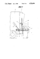
- FIG. 2 shows in side view a lifting and tipping device similar to that of FIG. 1, with the barrier elements closed and a refuse bin placed on it;
- FIG. 3 shows a diagrammatic view of the hydraulic drive and control system used in a device as shown in FIG. 1 or FIG. 2 for single tippers;
- FIG. 4 is a rear view of an emptying device according to the invention as a combination tipper, that is to say, with two lifting and tipping devices which can be actuated jointly or separately arranged next to one another;
- FIG. 5 is a diagrammatic view of the hydraulic drive and control system which may be used for a double or twin tipper, and
- FIG. 6 shows a diagrammatic view of the hydraulic drive and control system used in the device as shown in FIG. 4.
- FIGS. 1 and 2 concern a lifting and tipping device for emptying refuse bins 1 into a refuse collecting container 2 of a refuse lorry having a tipping-in device 3.
- the tipping-in device 3 may be designed as a single tipper or as a double, or twin, tipper; in the latter case it has two tipping devices or lifting and tipping devices 4 operating independently of one another.
- the lifting and tipping device 4 has a swivel arm 5 or a pair of swivel arms 5, to which a lifting and tipping frame 6 is attached by means of a four-bar guide mechanism (not illustrated in detail).
- the lifting and tipping frame 6 is equipped, in this example, on its upper part with a support ledge 7 engaging beneath the rim of the container 1, and on its lower part with an abutment element 8 which positions itself against the wall of the container 1.
- the diagrammatically illustrated hydraulic cylinder-piston arrangement 9 is used to raise and lower the lifting and tipping device 6. Locking of the container 1 is effected by the support ledge 7 pressing the container rim against the abutments 10 disposed on the swivel arms 5.
- the drive of the swivel arms 5 is effected by means of hydraulic cylinder-piston arrangements 11 which, in the Example illustrated, are designed as oscillating motors.
- the cylinder-piston unit 9 of the lifting device and the cylinder-piston unit 11 of the oscillating motor of each lifting and tipping device 4 are combined in a common power-pressure medium circuit (FIG. 3).
- This power-pressure medium circuit is so designed that at the start of operation it acts first of all on the cylinder-piston unit 9 of the lifting device and thereafter on the cylinder-piston unit 11 provided for the oscillating motor.
- the switch 12 which is provided for switching on the electrical control device for the automatic operation and is actuated by the container 1, is mounted beneath the support ledge 7 on the side of the lifting and tipping frame 6 facing the container wall.
- this switch it would be possible to arrange this switch at other positions on the lifting and tipping frame 6, for example in the region of the abutment part 8.
- a non-contact sensor, or a light barrier, or similar means could be provided instead of the contact switch 12.
- a hand-operated switch for example a switch 12, which is located on the tipper housing at a point within easy reach of the operator.
- this hand-operated switch 13 is combined with the control valve 36 arranged in the power-pressure medium circuit such that both parts have a common electromagnetic actuating device 36a and a common hand-operated element 14.
- the hand-operated switch 13 in this Example is constructed as a magnetic sensor switch, which is brought from one switch position to the other on the approach of the actuating rod guided axially through the electromagnetic actuating device 36a and the control valve 36.
- two barrier elements 15 are pivotally mounted on the lateral walls of the refuse lorry. These barrier elements may be combined bow-like on a common pivot axle.
- the barrier elements 15 may be pivoted by hand into and out of their safety position. When they pass a dead centre position, they are held in their respective upper and lower positions by a retaining spring 15b designed as a tension spring.
- a pressure medium motor 15a or a pair of pressure medium motors 15a are provided for setting the barrier elements 15.
- the barrier elements 15 actuate a switch 16 in their safety position.
- an hydraulic pressure medium system which is fed by the pressure medium pump 33 is provided.
- an pressure medium feed line 34 leads via a pressure medium check valve 35 to a control valve 36 constructed as a two-position valve.
- a control valve 36 constructed as a two-position valve.
- a pressure medium inlet line 37 which leads to the pressure medium motors arranged in parallel, namely the lifting cylinder 9 and the pivoting cylinder 11.
- a pressure relief valve 38 with actuating element 39 is attached to the pressure medium inlet line 37.
- a pressure medium relief line 40 leads to a pressure medium return valve 41, which is inserted in the pressure medium return line 42, to improve the return of pressure medium and therewith the return movement of the cylinder piston assemblies 9 and 11.
- a bypass line 43 leads from the control valve 36 to the pressure medium return valve 41.
- the pressure medium return line 42 leads into a pressure medium reservoir 43a from which the pressure medium pump 33 draws the required amount of pressure medium for the system and introduces it into the pressure medium-power circuit by way of the pressure medium feed line 34.
- a control circuit for controlling this pressure medium-power circuit; it comprises the switch 12 mounted on the lifting and tipping frame 6 and actuated by the container placed thereon, and a time relay 45 connected in series with the switch 12.
- This time relay 45 is connected to the electrical operating device of the reversing valve 36 of the pressure medium-power circuit.
- the time constant of the time relay 45 is set to the duration required by the lifting and tipping device, from lifting the container, through pivoting it, until the container is completely empty.
- the lifting cylinder 9 is designed to be more powerful than the pivoting cylinder 11.
- the pressure relief valve 38 drawn in FIG. 3 is that, in the end tipped position, a pivot limiting lever set on the pivot axle of the lifting and tipping device 4 and twisted in accordance with the swing of the pivot axle, strikes with its adjusting screw the actuating element 39 of the pressure relief valve 38.
- the pressure relief valve 38 which was previously in the closed position, is then brought against the action of its regulating spring into a partially open position, so that there is a reduction in pressure in the pressure medium inlet line 37 by way of the pressure relief line 40 to the pressure medium return valve 41.
- the pressure relief valve 38 With a sufficiently large control interval between the actuation of the relief valve 38 and the final position of the pivot limiting lever, the pressure relief valve 38 is then opened sufficiently far for a sharp drop in pressure to occur in the pressure medium inlet line 34. This sharp decrease in pressure medium enables the lifting and tipping device, together with the container to be emptied, to pivot back sufficiently far for the pressure relief valve 38 to close again.
- the inflowing pressure medium causes a renewed pivoting of the lifting and tipping device until the adjusting screw of the pivot limiting lever again meets the actuating element 39 of the pressure relief valve 38, and thus the decrease in pressure medium in the pressure medium inlet line 37 with the pressure relief valve open causes a corresponding return pivoting of the lifting and tipping device together with the container to be emptied. In this manner a kind of vibrating motion is produced, so that complete emptying of the container is ensured.
- the complete return pivoting movement and setting down of the container is initiated in that the time relay 45, after the set duration has elapsed, interrupts the connection between the electrical actuating device of the reversing valve 36 and the source of electricity 44, whereby the reversing valve 36 is switched by means of its restoring spring into the rest position.
- the pressure medium coming from the pressure medium supply 33 by way of the pressure medium feed line 34 then flows away by way of the bypass line 43 through the return valve 41, exerting as it does so a suction on the return line 42 and thus reinforcing the backflow effect of the pressure medium flowing out of the cylinders 9 and 11 by way of the pressure medium inlet line 37 and the pressure medium return line 42.
- valve 80 which rhythmically interrupts or constricts the admission of pressure medium.
- This valve 80 is switched in by the time relay 45 at a point in time at which the tipping process has advanced by a desired extent.
- the container is hereby displaced into a gentle shaking motion whereby the container is competely emptied of its contents.
- the valve 80 is cut out by the time relay 45 on commencement of the return pivoting process.
- the emptying device is arranged on a refuse lorry, it is advantageous to use the vehicle battery as the source of electricity 44. In the case of a stationary collecting container, it would also be conceivable to provide the control circuit with a mains terminal.
- control valve 36 illustrated in FIG. 3 in its design as a two-position valve, it is also possible to use a three-position valve with an operative, return and rest position. In this case, however, more complicated components of the control circuit are required, or a more complex actuating element for such a reversing valve, for example a second time relay which, after the switch contact has been opened by the first time element, i.e. after the container has been emptied, brings the three-position reversing valve into the return position by means of the actuating device.
- a second time relay which, after the switch contact has been opened by the first time element, i.e. after the container has been emptied, brings the three-position reversing valve into the return position by means of the actuating device.
- FIG. 3 shows, in the pressure medium feed line 34 there is inserted a two-position shut-off valve 34a which is connected with its electromagnetic actuating device via the switch 16 operated by the barrier element 15 to the electrical control circuit.
- the switch 16 When the switch 16 is closed, the shut-off valve 34a is put into the position shown in FIG. 3, in which it clears the passage for the hydraulic pressure medium to the pressure medium feed line 34.
- the switch 16 When the switch 16 is open, the shut-off valve 34a positions itself under the influence of its spring in the second position, in which a bypass line 43b leading back to the pressure medium reservoir 43a is connected to the pressure side of the pump 33.
- the emptying device as shown in FIG. 1 or FIG. 2 is constructed as a twin or double tipper, that is to say, is equipped with two adjacent lifting and tipping devices 4, then two identical control systems as shown in FIG. 3 may be provided, namely one for each lifting and tipping device 4.
- a control system as shown in FIG. 5 may be used.
- the operation of the twin or double tipper is as follows, wherein corresponding components from FIG. 3 and FIG. 5 have been given the same reference numerals, but in FIG. 4 are additionally provided with letters (a) and (b):
- the two pressure medium-power circuits have a common pressure medium pump downstream of which is connected a pressure-independent pressure medium flow divider 46, so that each pressure medium-power circuit has its own pressure medium source.
- a common source of electricity 44 is also provided for each of the two control circuits.
- each of the two single lifting and tipping devices does not act directly on the control valve 36a, 36b of the power-pressure medium circuit, but controls in its turn a pneumatic control pressure medium circuit.
- Each of these two control pressure medium circuits consists of a reversing valve 47a, 47b adjusted for electrical operation and connected to the corresponding control circuit, which reversing valve is attached to a supply line 48a, 48b.
- This pneumatic control pressure medium line 48a, 48b is attached to a working cylinder 49a, 49b loaded by a restoring spring, the piston rod 50a, 50b of which working cylinder serves as the element for actuating the control valve 36a, 36b.
- a common pressure medium supply 51 which is connected to the pneumatic valves 47a, 47b via the branch lines 51a, 51b, is provided for the two pneumatic control pressure medium circuits.
- the pneumatic pressure medium source already present for the brake system of the vehicle may be used concomitantly as the pressure medium source 51.
- the return pivoting and setting down operation of the lifting and tipping frame with the now emptied container is effected again as a result of the time relay 45a, 45b interrupting the circuit between the pneumatic valves 47a, 47b adjusted for electrical operation and the source of electricity 44.
- the pneumatic valve 47a, 47b is therefore brought into the neutral position by the restoring force of its spring so that the source of pneumatic pressure medium 51 is disconnected from the pressure medium control circuit.
- the emptying device shown in FIG. 4 is a so-called combination tipper, by means of which both relatively small refuse bins and a larger container may be emptied.
- two adjacent lifting and tipping devices 17a, 17b are arranged on the rear of the tipping-in device 18.
- the drive of each of these lifting and tipping devices 17a, 17b is effected by way of their own cylinder-piston arrangements (not shown) having separate pressure medium-power circuits, so that these may be operated individually for emptying smaller containers.
- the manner in which the combination tipper functions is comparable with that of two single tippers, as explained above.
- each individual lifting and tipping device consists of the known four-bar system which is coordinated with the lifting and tipping frame 21a, 21b by means of the abutment plate 20a, 20b.
- Locking of the containers is effected by the support ledges 22a, 22b pressing the container rim against the locating plates 24a, 24b arranged at the upper end of the swivel arms 23a, 23b.
- a connecting and supporting beam is affixed, for example by means of screws, to the two support ledges 22a, 22b.
- This connecting and supporting beam 25 is, in the Example illustrated, constructed on its upper side with teeth-like holding projections 26a, 26b arranged at intervals so that it is able to hold containers, for example refuse bins, of widely differing upper rim designs.
- an intermediate buffer 27, illustrated by a broken line, may be provided for selective use; it would be arranged between the two abutments parts 20a, 20b.
- pivoting support arms 28a, 28b having receiving claws 29a, 29b for the carrying lugs of these refuse bins are additionally provided on the two lifting and tipping frames 21a, 21b.
- the movement sequence is controlled electrically with fixed time constants for the valve control of the power-pressure medium circuit
- the power-pressure medium circuits of the two single lifting and tipping devices have their own control circuit.
- the switches for initiating the control sequence and actuated by the containers placed in position on the frame are located on the lifting and tipping frame 21a, 21b such that, when the connecting and supporting beam 25 is attached, i.e. when the combination tipper is equipped for synchronous operation of the two individual tippers for emptying larger containers, these switches do not come into contact with the container wall.
- this main switch may be designed and arranged in such a manner that when the connecting and supporting beams 25, or any other connecting element, is disposed between the two lifting and tipping frames 21a and 21b, it is brought into the position in which it switches off the automatic control.
- the two power-pressure medium circuits of the two lifting and tipping devices 17a,17b are connected to one another by means of reversing valves in such a manner that their pressure medium motors are switched in parallel, and are fed from only one source of pressure medium.
- one of the two hand-operated switches 31a, 31b arranged on the tipper housing has to be actuated.
- this hand-operated switch serves for the manual control of the lifting and tipping devices 17a, 17b, should the electrical controls for the automated operation fail.
- two locking hand-operated switches 32a, 32b are provided on the collecting container housing 18.
- FIG. 6 shows a diagrammatic view of an hydraulic drive system and electrical control system for a combination tipper, as illustrated in FIG. 2.
- two hydraulic power-pressure medium circuits which are selectively separated or connected by way of a reversing valve 53 are also provided in this combination tipper.
- Each of these pressure medium circuits has its own source of pressure medium which, in the Example illustrated, may be formed by a respective branch 54a, 54b of a pressure-independent flow divider 54 in conjunction with a pressure medium pump 55 arranged upstream of this flow divider.
- each power-pressure medium circuit there leads from this pressure medium source 54a, 54b a pressure medium feed line 56a, 56b by way of a check valve 57, 57b to the respective reversing valve 52a, 52b.
- This control valve 52a, 52b is joined in the neutral position to a bypass line 58a, 58b which is joined by way of a pressure medium return valve 59a, 59b to the pressure medium return line 60a, 60b.
- the reversing valve 52a, 52b is joined to a pressure medium supply line 61a, 61b which conveys the hydraulic operating medium to the pressure medium motors 62a, 63a and 62b, 63b arranged in parallel.
- a reversing valve 65 which is switched into the blocking position only in synchronous operation of the two tippers. All other components of the two power-pressure medium circuits and control circuits are arranged in an identical manner.
- a pressure medium relief valve 66a, 66b with actuating elements 67a, 67b is joined to each pressure medium inlet line 61a, 61b. From these pressure medium relief valves 66a, 66b pressure medium relief lines 68a, 68b lead to the pressure medium guide valves 59a, 59b.
- the control of the pressure medium-power circuits is effected, as in the embodiment illustrated in FIG. 3, by direct action on the reversing valve 52a, 52b adjusted for electrical actuation.
- the electrical control circuits consist in each case of a time relay 69a, 69b, an operating switch 70a, 70b arranged on the lifting and tipping frame of each individual tipper, and parallel thereto a hand-operated element 71a, 71b.
- a switch 74 actuated when the barrier elements are in the safety position. Between this switch contact 74 and the electricity source 73 there is additionally arranged a locking switch 75.
- the reversing valve 53 installed in the line 64 connecting the two pressure medium circuits, and the reversing valve 65 installed in the pressure medium inlet line 61a of just one pressure medium circuit, are arranged for an electrical actuation and, together with the control circuits, are connected to the source of electricity 73.
- Both reversing switches 53 and 65 are inversely switched, however, in such a manner that in individual operation of the two tippers the reversing valve 53 is in the block position and the reversing valve 65 is in the open position. In this mode of operation the switch 75 is closed, that is to say, is unlocked.
- the reversing switch 65 installed in the pressure medium inlet line 61a is switched by spring force into the block position and the reversing switch 53 installed in the connecting line 64 is switched by spring force into the open position, whereupon a parallel circuit of all pressure medium assemblies 62a, 62b, 63a, 63b is produced and the emptying device is ready for synchronous operation of the two individual tippers for emptying large containers.
- the reversing valve 52b has to be actuated by means of the adjusting member 76b by hand.
- the two lifting cylinders 63a, 63b and the two pivoting cylinders 62a, 62b are charged with the same amount of pressure medium as only one liftiny cylinder 63a and one pivoting cylinder 62a in the individual control.
- a fully automatic emptying device could also be provided within the scope of the invention, with which emptying of containers of any size can be carried out automatically.
- a fully automatic emptying device is provided, for example, with a programming and switching device to which identification data such as type, size, mounting site etc. for the containers to be emptied are to be fed.
- a fully automatic device contains in its control system a memory with data about the containers that are to be emptied. By this means, using switching arrangements, comparisons can be drawn between the identification data fed in and the stored data.
- an emptying procedure suitable for the container in question, or the method of controlling the emptying device for this emptying procedure can be selected and, by means of switching devices, can be set on the respective control elements of the emptying device.
- the lifting and tipping frame, or tipping frame can be brought into a suitable preliminary position for the container to be emptied even prior to the commencement of the emptying procedure.
- the emptying speed may be preselected.
- all parameters of the emptying process can be automatically preselected and set by this fully automatic device using the data of the container identified in each case, and the contents thereof.
- such a fully automatic device may be equipped with a device monitoring the weight of the emptied container, which device refers back to the emptying control system and has the emptying process repeated when the weight of the emptied container still lies above the desired weiht, that is to say, when a container has not been completely emptied.
- registering and recording devices may be provided which establish the identity of the emptied containers and the weight of contents emptied from each container, and also any damage to or other iregularities concerning the emptied containers.
Landscapes
- Engineering & Computer Science (AREA)
- Mechanical Engineering (AREA)
- Refuse-Collection Vehicles (AREA)
- Refuse Collection And Transfer (AREA)
- Refuse Receptacles (AREA)
- Drying Of Solid Materials (AREA)
- Control And Other Processes For Unpacking Of Materials (AREA)
- Filtering Of Dispersed Particles In Gases (AREA)
- Electrical Discharge Machining, Electrochemical Machining, And Combined Machining (AREA)
Applications Claiming Priority (1)
| Application Number | Priority Date | Filing Date | Title |
|---|---|---|---|
| DE3405997A DE3405997C2 (de) | 1984-02-20 | 1984-02-20 | Vorrichtung zum Entleeren von Behältern, insbesondere von Müllbehältern in Sammelbehälter |
Related Child Applications (1)
| Application Number | Title | Priority Date | Filing Date |
|---|---|---|---|
| US13102587A Continuation | 1984-02-20 | 1987-12-10 |
Publications (1)
| Publication Number | Publication Date |
|---|---|
| US4722656A true US4722656A (en) | 1988-02-02 |
Family
ID=6228219
Family Applications (1)
| Application Number | Title | Priority Date | Filing Date |
|---|---|---|---|
| US06/788,939 Expired - Lifetime US4722656A (en) | 1984-02-20 | 1985-02-15 | Device for emptying containers, especially refuse bins |
Country Status (14)
| Country | Link |
|---|---|
| US (1) | US4722656A (cs) |
| EP (2) | EP0156445B1 (cs) |
| JP (1) | JPH07112881B2 (cs) |
| AT (1) | ATE35122T1 (cs) |
| AU (1) | AU573811B2 (cs) |
| CA (1) | CA1259959A (cs) |
| CS (1) | CS275990B6 (cs) |
| DD (1) | DD233355A5 (cs) |
| DE (1) | DE3405997C2 (cs) |
| ES (1) | ES8606174A1 (cs) |
| GR (1) | GR850433B (cs) |
| PT (1) | PT79991B (cs) |
| WO (1) | WO1985003689A2 (cs) |
| ZA (1) | ZA851246B (cs) |
Cited By (20)
| Publication number | Priority date | Publication date | Assignee | Title |
|---|---|---|---|---|
| US4824315A (en) * | 1986-07-21 | 1989-04-25 | Zoller-Kipper Gmbh | Equipment for emptying containers statement as to rights to inventions made under federally-sponsored research and development |
| US5038876A (en) * | 1990-03-05 | 1991-08-13 | Wray-Tech Instruments, Inc. | Hydraulic control system for weighing |
| US5056979A (en) * | 1990-05-25 | 1991-10-15 | Toter, Inc. | Lift unit for lifting and emptying waste containers |
| US5062759A (en) * | 1989-04-03 | 1991-11-05 | Zoller-Kipper Gmbh | Safety circuit arrangement for lifting/tilting or tilting devices |
| US5064333A (en) * | 1987-10-20 | 1991-11-12 | Otto Lift-Systeme Gmbh | Apparatus for emptying containers, particularly refuse containers |
| US5064008A (en) * | 1990-03-05 | 1991-11-12 | Wray-Tech Instruments, Inc. | Hydraulic control system for weighing |
| US5145305A (en) * | 1989-10-18 | 1992-09-08 | Waste Hoists Limited | Collection vehicle, apparatus for use in the vehicle and method of collecting material |
| US5322407A (en) * | 1991-08-30 | 1994-06-21 | Zoller-Kipper Gmbh | Equipment for emptying containers |
| US5631835A (en) * | 1984-04-27 | 1997-05-20 | Hagenbuch; Leroy G. | Apparatus for identifying containers from which refuse is collected and compiling a historical record of the containers |
| US5650928A (en) * | 1984-04-27 | 1997-07-22 | Hagenbuch; Leroy G. | Apparatus and method responsive to the on-board measuring of haulage parameters of a vehicle |
| GB2322351A (en) * | 1997-02-06 | 1998-08-26 | Hoist Technology Limited | Hoist for refuse containers |
| US5879015A (en) * | 1992-02-10 | 1999-03-09 | Ramsey; Michael P. | Method and apparatus for receiving material |
| EP0962401A1 (en) * | 1998-06-05 | 1999-12-08 | Geesink B.V. | Loading device for a refuse collection device provided with safety means |
| NL1009325C2 (nl) * | 1998-06-05 | 2000-02-01 | Geesink Bv | Inrichting voor het legen van afvalhouders in een verzamelhouder |
| EP1201568A1 (en) * | 2000-10-17 | 2002-05-02 | Mol CY NV | Protected device for emptying refuse bins in a collecting container |
| US20060244474A1 (en) * | 2005-04-29 | 2006-11-02 | Hlotyak Stephen J | Site-aware objects |
| WO2006047763A3 (en) * | 2004-10-27 | 2009-04-16 | Paceco Corp | Method and apparatus using radio-location tags to report status for a container handler |
| US20100030370A1 (en) * | 2004-05-14 | 2010-02-04 | King Henry S | Method and apparatus for making status reporting devices for container handlers |
| NL2010344C2 (nl) * | 2013-02-22 | 2014-08-25 | Schijndel Holding B V Van | Inrichting en werkwijze voor het verwerken van vertrouwelijk materiaal. |
| US12391469B2 (en) | 2021-07-23 | 2025-08-19 | Micromatic Llc | Cart tipper protection device and process |
Families Citing this family (28)
| Publication number | Priority date | Publication date | Assignee | Title |
|---|---|---|---|---|
| US5004392A (en) * | 1984-02-20 | 1991-04-02 | Zoller-Kipper Gmbh | Device for emptying containers, especially refuse bins |
| DE3447648C2 (de) * | 1984-12-28 | 1986-12-11 | Garbade, Rolf, 2804 Lilienthal | Verfahren und Vorrichtung zur gewichtsmäßigen Erfassung von Material, vorzugsweise Müll, bei der Entleerung in ein Sammelfahrzeug |
| DE3517491A1 (de) * | 1985-05-15 | 1986-11-20 | G + S Umwelttechnik GmbH, 7107 Nordheim | Hub- oder hub-kipp-vorrichtung zum entleeren von muellbehaeltern in muellfahrzeuge |
| US4771837A (en) * | 1986-10-20 | 1988-09-20 | Breakthru Industries, Inc. | Weighing system |
| DE3819169A1 (de) * | 1988-06-04 | 1989-12-07 | Pfister Gmbh | Verfahren und system zur waegung des inhalts von muelltonnen |
| DE3907441A1 (de) * | 1989-03-08 | 1990-09-13 | Otto Lift Systeme Gmbh | Vorrichtung zum entleeren von insbesondere muellbehaeltern |
| DE3910791C2 (de) * | 1989-04-04 | 1994-08-11 | Bernd Dipl Ing Merle | Verfahren und Einrichtung zur Ermittlung von Entsorgungsgebühren |
| NL193187C (nl) * | 1989-09-29 | 1999-02-02 | Terberg Machines | Transportvoertuig voor afval met een containerlosinrichting en een beveiligingsconstructie. |
| DE4010065A1 (de) * | 1990-03-29 | 1991-10-02 | Franz Sperner | Verfahren zum mengenbezogenen entsorgen von haushalts-und gewerbemuell und mengenbezogenes entsorgungssysstem fuer derartigen muell |
| US5139101A (en) * | 1991-04-10 | 1992-08-18 | Wray-Tech Instruments, Inc. | Hydraulic control system for weighing and two-way valve therefor |
| BE1005209A5 (nl) * | 1991-08-29 | 1993-05-25 | All Round Consulting | Kunststofcontainer voor afval voorzien van een identificatiemiddel en apparaat voor het lezen van de daarin opgeslagen identificatiecode. |
| DE4134344A1 (de) * | 1991-10-17 | 1993-04-22 | Wds Wiege Und Datensysteme Gmb | Vorrichtung zum gewichtsmaessigen erfassen von material, vorzugsweise muell, an einem sammelfahrzeug |
| DE4136045C2 (de) * | 1991-11-01 | 1993-10-07 | Zoeller Kipper | Sicherheitsschranke |
| DE9206606U1 (de) * | 1992-05-15 | 1992-07-23 | Zöller-Kipper GmbH, 6500 Mainz | Trittbrett für Müllfahrzeuge |
| DE4234995C1 (en) * | 1992-10-16 | 1993-09-23 | Kellner, Rainer, 70825 Korntal-Muenchingen, De | Emptiness checking device for refuse containers - performs photoelectric detection of completion of flow of material out of upturned container into vehicle. |
| DE4415060C1 (de) * | 1994-04-29 | 1995-09-28 | Zoeller Kipper | Hubkipp- oder Kippvorrichtung zum Entleeren von Müllbehältern |
| DE4430833C1 (de) * | 1994-08-31 | 1995-11-23 | Zoeller Kipper | Verfahren und Vorrichtung zum Absichern des Arbeitsbereichs von Entleereinrichtungen |
| DE19536629C2 (de) * | 1995-09-22 | 2002-10-24 | Hilmar Meister | Verfahren und Vorrichtung zur Ermittlung verursachergerechter Müllentsorgungsgebühren in Großwohnanlagen |
| EP1031520A1 (de) | 1999-02-22 | 2000-08-30 | Zöller-Kipper GmbH | Vorrichtung zum Entleeren von Behältern, insbesondere Müllbehältern |
| DE102004036363B4 (de) * | 2004-07-22 | 2006-11-23 | Zöller-Kipper GmbH | Verfahren und Vorrichtung zur Absicherung des Arbeitsbereiches von Entleervorrichtungen |
| NL2004148C2 (nl) | 2010-01-26 | 2011-07-27 | Terberg Machines | Beladingssyssteem, vuilnisauto en werkwijze daarvoor. |
| DE102013223840A1 (de) | 2013-11-21 | 2015-05-21 | Zöller-Kipper GmbH | Sicherheitsvorrichtung |
| CN109264267A (zh) * | 2018-10-23 | 2019-01-25 | 凌丽霞 | 一种滑轮提升式垃圾回收车 |
| CN111284063B (zh) * | 2020-03-03 | 2021-11-12 | 福建龙马环卫装备股份有限公司 | 移动式垃圾压缩箱满箱判定方法 |
| WO2023073230A1 (en) * | 2021-10-31 | 2023-05-04 | Emdot Single Member Societe Anonyme | A system installable on a garbage truck for weighing garbage containers, a related use and a garbage truck |
| DE102023104795A1 (de) * | 2023-02-28 | 2024-08-29 | Zöller-Kipper Gesellschaft mit beschränkter Haftung | Schaltanordnung |
| DE102024106252A1 (de) | 2024-03-05 | 2025-09-11 | Faun Umwelttechnik Gmbh & Co. Kg | Nutzfahrzeug |
| DE202024101053U1 (de) | 2024-03-05 | 2024-05-08 | Faun Umwelttechnik Gmbh & Co. Kg | Nutzfahrzeug |
Citations (7)
| Publication number | Priority date | Publication date | Assignee | Title |
|---|---|---|---|---|
| US3263842A (en) * | 1963-08-12 | 1966-08-02 | Schenley Distillers Co Inc | Case dumper |
| US3332560A (en) * | 1961-05-27 | 1967-07-25 | Fr Niepmann G M B H & Co Masch | Cigarette container emptying device |
| US3599806A (en) * | 1969-12-04 | 1971-08-17 | Int Harvester Co | Bale wagon |
| US3738516A (en) * | 1972-07-31 | 1973-06-12 | L Wells | Container lifting mechanism |
| GB1399454A (en) * | 1971-06-22 | 1975-07-02 | Shelvoke Drewry Ltd | Container lifting and tipping mechanism |
| US4259035A (en) * | 1977-09-13 | 1981-03-31 | Sperry Corporation | Agricultural bale accumulator |
| US4544280A (en) * | 1982-12-11 | 1985-10-01 | Satake Engineering, Co., Ltd. | Grain handling system |
Family Cites Families (10)
| Publication number | Priority date | Publication date | Assignee | Title |
|---|---|---|---|---|
| NL105000C (cs) * | 1956-05-08 | |||
| DE1228560B (de) * | 1965-06-18 | 1966-11-10 | Streuber Sulo Eisenwerk F | Steuervorrichtung fuer Muellgefaess-Hubkippvorrichtungen an Muellsammelwagen |
| FR1554603A (cs) * | 1966-11-18 | 1969-01-24 | ||
| AT302902B (de) * | 1970-01-02 | 1972-11-10 | Ochsner & Cie Ag J | Einrichtung zur staubfreien Entleerung von Kehrichteimern |
| DE2721059A1 (de) | 1977-05-11 | 1978-11-23 | Severin Kuepper | Vorrichtung zum heben, entleeren und senken von muellbehaeltern oder containern |
| DE2847259A1 (de) * | 1978-10-31 | 1980-05-08 | Zoeller Kipper | Hub-kipp- oder kippvorrichtung zum entleeren von behaeltern unterschiedlicher groesse |
| DE2851084C2 (de) * | 1978-11-25 | 1982-09-30 | Fahrzeugbau Haller Gmbh, 7000 Stuttgart | Steuereinrichtung für eine Beladevorrichtung für Schüttgutbehälter |
| US4417839A (en) * | 1979-10-16 | 1983-11-29 | The United States Of America As Represented By The Secretary Of Agriculture | Automatic hatchery tray dumper |
| DE3123191A1 (de) * | 1980-06-11 | 1982-03-25 | Glover Webb & Liversidge Ltd., Hamble, Hampshire | Vorrichtung zum anheben und kippen von muellcontainern |
| DE3041630A1 (de) * | 1980-11-05 | 1982-05-13 | Schörling GmbH & Co Waggonbau, 3000 Hannover | Elektrohydraulische steuerung der belade-, press- und entleerungseinrichtung eines muellfahrzeuges |
-
1984
- 1984-02-20 DE DE3405997A patent/DE3405997C2/de not_active Expired
-
1985
- 1985-02-15 AU AU41112/85A patent/AU573811B2/en not_active Ceased
- 1985-02-15 EP EP85200470A patent/EP0156445B1/de not_active Expired
- 1985-02-15 US US06/788,939 patent/US4722656A/en not_active Expired - Lifetime
- 1985-02-15 AT AT85200470T patent/ATE35122T1/de not_active IP Right Cessation
- 1985-02-15 WO PCT/EP1985/000052 patent/WO1985003689A2/de not_active Ceased
- 1985-02-15 EP EP85901399A patent/EP0173727A1/de active Pending
- 1985-02-15 JP JP60501308A patent/JPH07112881B2/ja not_active Expired - Lifetime
- 1985-02-19 ZA ZA851246A patent/ZA851246B/xx unknown
- 1985-02-19 CS CS851162A patent/CS275990B6/cs not_active IP Right Cessation
- 1985-02-19 DD DD85273371A patent/DD233355A5/de not_active IP Right Cessation
- 1985-02-19 ES ES540519A patent/ES8606174A1/es not_active Expired
- 1985-02-19 GR GR850433A patent/GR850433B/el not_active IP Right Cessation
- 1985-02-20 CA CA000474757A patent/CA1259959A/en not_active Expired
- 1985-02-20 PT PT79991A patent/PT79991B/pt active IP Right Revival
Patent Citations (7)
| Publication number | Priority date | Publication date | Assignee | Title |
|---|---|---|---|---|
| US3332560A (en) * | 1961-05-27 | 1967-07-25 | Fr Niepmann G M B H & Co Masch | Cigarette container emptying device |
| US3263842A (en) * | 1963-08-12 | 1966-08-02 | Schenley Distillers Co Inc | Case dumper |
| US3599806A (en) * | 1969-12-04 | 1971-08-17 | Int Harvester Co | Bale wagon |
| GB1399454A (en) * | 1971-06-22 | 1975-07-02 | Shelvoke Drewry Ltd | Container lifting and tipping mechanism |
| US3738516A (en) * | 1972-07-31 | 1973-06-12 | L Wells | Container lifting mechanism |
| US4259035A (en) * | 1977-09-13 | 1981-03-31 | Sperry Corporation | Agricultural bale accumulator |
| US4544280A (en) * | 1982-12-11 | 1985-10-01 | Satake Engineering, Co., Ltd. | Grain handling system |
Cited By (27)
| Publication number | Priority date | Publication date | Assignee | Title |
|---|---|---|---|---|
| US5631835A (en) * | 1984-04-27 | 1997-05-20 | Hagenbuch; Leroy G. | Apparatus for identifying containers from which refuse is collected and compiling a historical record of the containers |
| US5995888A (en) * | 1984-04-27 | 1999-11-30 | Hagenbuch; Leroy G. | Apparatus and method responsive to the on-board measuring of haulage parameters of a vehicle |
| US5742914A (en) * | 1984-04-27 | 1998-04-21 | Hagenbuch; Leroy G. | Apparatus and method responsive to the on-board measuring of haulage parameters of a vehicle |
| US5650928A (en) * | 1984-04-27 | 1997-07-22 | Hagenbuch; Leroy G. | Apparatus and method responsive to the on-board measuring of haulage parameters of a vehicle |
| US5644489A (en) * | 1984-04-27 | 1997-07-01 | Hagenbuch; Leroy G. | Apparatus and method for identifying containers from which material is collected and loaded onto a haulage vehicle |
| US4824315A (en) * | 1986-07-21 | 1989-04-25 | Zoller-Kipper Gmbh | Equipment for emptying containers statement as to rights to inventions made under federally-sponsored research and development |
| US5064333A (en) * | 1987-10-20 | 1991-11-12 | Otto Lift-Systeme Gmbh | Apparatus for emptying containers, particularly refuse containers |
| US5062759A (en) * | 1989-04-03 | 1991-11-05 | Zoller-Kipper Gmbh | Safety circuit arrangement for lifting/tilting or tilting devices |
| US5145305A (en) * | 1989-10-18 | 1992-09-08 | Waste Hoists Limited | Collection vehicle, apparatus for use in the vehicle and method of collecting material |
| US5064008A (en) * | 1990-03-05 | 1991-11-12 | Wray-Tech Instruments, Inc. | Hydraulic control system for weighing |
| US5038876A (en) * | 1990-03-05 | 1991-08-13 | Wray-Tech Instruments, Inc. | Hydraulic control system for weighing |
| US5056979A (en) * | 1990-05-25 | 1991-10-15 | Toter, Inc. | Lift unit for lifting and emptying waste containers |
| AU656788B2 (en) * | 1991-08-30 | 1995-02-16 | Zoller-Kipper Gmbh | Device for emptying containers |
| US5322407A (en) * | 1991-08-30 | 1994-06-21 | Zoller-Kipper Gmbh | Equipment for emptying containers |
| US5879015A (en) * | 1992-02-10 | 1999-03-09 | Ramsey; Michael P. | Method and apparatus for receiving material |
| GB2322351A (en) * | 1997-02-06 | 1998-08-26 | Hoist Technology Limited | Hoist for refuse containers |
| NL1009325C2 (nl) * | 1998-06-05 | 2000-02-01 | Geesink Bv | Inrichting voor het legen van afvalhouders in een verzamelhouder |
| EP0962401A1 (en) * | 1998-06-05 | 1999-12-08 | Geesink B.V. | Loading device for a refuse collection device provided with safety means |
| EP1201568A1 (en) * | 2000-10-17 | 2002-05-02 | Mol CY NV | Protected device for emptying refuse bins in a collecting container |
| US20100030370A1 (en) * | 2004-05-14 | 2010-02-04 | King Henry S | Method and apparatus for making status reporting devices for container handlers |
| US8188865B2 (en) | 2004-05-14 | 2012-05-29 | Paceco Corp. | Apparatus for a status reporting device for container handler |
| US8525671B2 (en) | 2004-05-14 | 2013-09-03 | Paceco Corp. | Method and apparatus for making status reporting devices for container handlers |
| WO2006047763A3 (en) * | 2004-10-27 | 2009-04-16 | Paceco Corp | Method and apparatus using radio-location tags to report status for a container handler |
| US20060244474A1 (en) * | 2005-04-29 | 2006-11-02 | Hlotyak Stephen J | Site-aware objects |
| NL2010344C2 (nl) * | 2013-02-22 | 2014-08-25 | Schijndel Holding B V Van | Inrichting en werkwijze voor het verwerken van vertrouwelijk materiaal. |
| EP2769934A1 (en) * | 2013-02-22 | 2014-08-27 | Van Schijndel Holding B.V. | Device and method for processing confidential material |
| US12391469B2 (en) | 2021-07-23 | 2025-08-19 | Micromatic Llc | Cart tipper protection device and process |
Also Published As
| Publication number | Publication date |
|---|---|
| CS8501162A2 (en) | 1991-06-11 |
| ES8606174A1 (es) | 1986-04-16 |
| CA1259959A (en) | 1989-09-26 |
| PT79991B (de) | 1986-10-28 |
| EP0156445A3 (en) | 1986-03-19 |
| ZA851246B (en) | 1985-10-30 |
| WO1985003689A2 (en) | 1985-08-29 |
| WO1985003689A3 (en) | 1985-10-24 |
| ES540519A0 (es) | 1986-04-16 |
| DE3405997C2 (de) | 1987-01-08 |
| PT79991A (de) | 1985-03-01 |
| EP0156445B1 (de) | 1988-06-15 |
| GR850433B (cs) | 1985-05-13 |
| DD233355A5 (de) | 1986-02-26 |
| JPS61501266A (ja) | 1986-06-26 |
| CS275990B6 (en) | 1992-03-18 |
| AU573811B2 (en) | 1988-06-23 |
| EP0173727A1 (de) | 1986-03-12 |
| JPH07112881B2 (ja) | 1995-12-06 |
| ATE35122T1 (de) | 1988-07-15 |
| DE3405997A1 (de) | 1985-08-22 |
| AU4111285A (en) | 1985-09-10 |
| EP0156445A2 (de) | 1985-10-02 |
Similar Documents
| Publication | Publication Date | Title |
|---|---|---|
| US4722656A (en) | Device for emptying containers, especially refuse bins | |
| US5004392A (en) | Device for emptying containers, especially refuse bins | |
| CA1118704A (en) | Hoisting/tipping or tipping device for emptying containers of varying size | |
| US3580166A (en) | Compaction apparatus | |
| ES2056668T3 (es) | Vehiculo colector de basura con un dispositivo elevador basculante para alojar y vaciar cubos de basura en un agujero de vertido. | |
| GB1589451A (en) | Lifting-tipping apparatus | |
| US4173424A (en) | Automatic packing system for refuse vehicle | |
| US5064333A (en) | Apparatus for emptying containers, particularly refuse containers | |
| JP3333240B2 (ja) | 容器を空ける装置 | |
| US4044664A (en) | System for the handling of solid waste | |
| EP0857669A2 (en) | Hoist for refuse containers | |
| US3625139A (en) | Refuse packing assembly for buildings and the like | |
| EP0857670A1 (en) | Refuse handling system | |
| CZ287974B6 (cs) | Zvedací vyklápěcí nebo vyklápěcí zařízení k vyprazdňování nádob na odpadky | |
| EP1067064B1 (en) | Front-loadable garbage truck | |
| JP4010628B2 (ja) | 塵芥収集車における積込制御装置 | |
| US4095519A (en) | Method for the handling of solid waste | |
| DK166613B1 (da) | Fremgangsmaade og anlaeg til overfoersel af affald | |
| SU1068351A1 (ru) | Устройство дл разгрузки контейнеров в кузов мусоровоза | |
| EP0413400A1 (en) | Transport vehicle with a container unloading device | |
| JP3989177B2 (ja) | 塵芥収集車 | |
| CA1043161A (en) | System and method for the handling of solid waste | |
| CZ288761B6 (cs) | Bezpečnostní ústrojí | |
| JP2559573Y2 (ja) | 塵芥収集車の油圧制御装置 | |
| JPH0454962Y2 (cs) |
Legal Events
| Date | Code | Title | Description |
|---|---|---|---|
| AS | Assignment |
Owner name: ZOLLER-KIPPER GMBH, HANS-ZOLLER-STRASSE 50-68, D-6 Free format text: ASSIGNMENT OF ASSIGNORS INTEREST.;ASSIGNOR:NAAB, JAKOB;REEL/FRAME:004717/0237 Effective date: 19851015 |
|
| STCF | Information on status: patent grant |
Free format text: PATENTED CASE |
|
| FPAY | Fee payment |
Year of fee payment: 4 |
|
| FPAY | Fee payment |
Year of fee payment: 8 |
|
| FPAY | Fee payment |
Year of fee payment: 12 |