JP6278633B2 - 薄膜トランジスタアレイ基板およびその製造方法、並びに、液晶表示装置およびその製造方法 - Google Patents
薄膜トランジスタアレイ基板およびその製造方法、並びに、液晶表示装置およびその製造方法 Download PDFInfo
- Publication number
- JP6278633B2 JP6278633B2 JP2013155544A JP2013155544A JP6278633B2 JP 6278633 B2 JP6278633 B2 JP 6278633B2 JP 2013155544 A JP2013155544 A JP 2013155544A JP 2013155544 A JP2013155544 A JP 2013155544A JP 6278633 B2 JP6278633 B2 JP 6278633B2
- Authority
- JP
- Japan
- Prior art keywords
- electrode
- film
- source
- array substrate
- gate
- Prior art date
- Legal status (The legal status is an assumption and is not a legal conclusion. Google has not performed a legal analysis and makes no representation as to the accuracy of the status listed.)
- Active
Links
- 239000000758 substrate Substances 0.000 title claims description 120
- 239000004973 liquid crystal related substance Substances 0.000 title claims description 36
- 238000004519 manufacturing process Methods 0.000 title claims description 34
- 239000010409 thin film Substances 0.000 title claims description 30
- 239000010408 film Substances 0.000 claims description 266
- 230000007547 defect Effects 0.000 claims description 115
- 239000004065 semiconductor Substances 0.000 claims description 56
- 238000000034 method Methods 0.000 claims description 54
- 238000007689 inspection Methods 0.000 claims description 42
- 229910052751 metal Inorganic materials 0.000 claims description 38
- 239000002184 metal Substances 0.000 claims description 38
- 239000011229 interlayer Substances 0.000 claims description 25
- 238000005530 etching Methods 0.000 claims description 17
- 239000010410 layer Substances 0.000 claims description 16
- 238000000059 patterning Methods 0.000 claims description 14
- 229910045601 alloy Inorganic materials 0.000 claims description 11
- 239000000956 alloy Substances 0.000 claims description 11
- 229910052709 silver Inorganic materials 0.000 claims description 8
- 230000000149 penetrating effect Effects 0.000 claims description 2
- 230000008569 process Effects 0.000 description 44
- 235000019557 luminance Nutrition 0.000 description 34
- 238000000206 photolithography Methods 0.000 description 22
- 230000015572 biosynthetic process Effects 0.000 description 16
- 230000008439 repair process Effects 0.000 description 13
- 230000005684 electric field Effects 0.000 description 7
- 239000000463 material Substances 0.000 description 6
- 229910021417 amorphous silicon Inorganic materials 0.000 description 5
- 229910021420 polycrystalline silicon Inorganic materials 0.000 description 5
- 229910052581 Si3N4 Inorganic materials 0.000 description 4
- VYPSYNLAJGMNEJ-UHFFFAOYSA-N Silicium dioxide Chemical compound O=[Si]=O VYPSYNLAJGMNEJ-UHFFFAOYSA-N 0.000 description 4
- 229910052804 chromium Inorganic materials 0.000 description 4
- 229910052802 copper Inorganic materials 0.000 description 4
- 238000001514 detection method Methods 0.000 description 4
- 229910052737 gold Inorganic materials 0.000 description 4
- 229910052750 molybdenum Inorganic materials 0.000 description 4
- 229910052759 nickel Inorganic materials 0.000 description 4
- HQVNEWCFYHHQES-UHFFFAOYSA-N silicon nitride Chemical compound N12[Si]34N5[Si]62N3[Si]51N64 HQVNEWCFYHHQES-UHFFFAOYSA-N 0.000 description 4
- 229910052814 silicon oxide Inorganic materials 0.000 description 4
- 238000004544 sputter deposition Methods 0.000 description 4
- 229910052719 titanium Inorganic materials 0.000 description 4
- 229910052721 tungsten Inorganic materials 0.000 description 4
- 230000000694 effects Effects 0.000 description 3
- 239000011521 glass Substances 0.000 description 3
- 239000012535 impurity Substances 0.000 description 3
- 230000003287 optical effect Effects 0.000 description 3
- 230000010287 polarization Effects 0.000 description 3
- 241000270281 Coluber constrictor Species 0.000 description 2
- OAICVXFJPJFONN-UHFFFAOYSA-N Phosphorus Chemical compound [P] OAICVXFJPJFONN-UHFFFAOYSA-N 0.000 description 2
- 229910052782 aluminium Inorganic materials 0.000 description 2
- 238000005229 chemical vapour deposition Methods 0.000 description 2
- 210000002858 crystal cell Anatomy 0.000 description 2
- 238000005520 cutting process Methods 0.000 description 2
- OQZCSNDVOWYALR-UHFFFAOYSA-N flurochloridone Chemical compound FC(F)(F)C1=CC=CC(N2C(C(Cl)C(CCl)C2)=O)=C1 OQZCSNDVOWYALR-UHFFFAOYSA-N 0.000 description 2
- 238000002347 injection Methods 0.000 description 2
- 239000007924 injection Substances 0.000 description 2
- 239000011159 matrix material Substances 0.000 description 2
- 229910052698 phosphorus Inorganic materials 0.000 description 2
- 239000011574 phosphorus Substances 0.000 description 2
- 229920005591 polysilicon Polymers 0.000 description 2
- 229910052715 tantalum Inorganic materials 0.000 description 2
- 238000007740 vapor deposition Methods 0.000 description 2
- GYHNNYVSQQEPJS-UHFFFAOYSA-N Gallium Chemical compound [Ga] GYHNNYVSQQEPJS-UHFFFAOYSA-N 0.000 description 1
- XLOMVQKBTHCTTD-UHFFFAOYSA-N Zinc monoxide Chemical compound [Zn]=O XLOMVQKBTHCTTD-UHFFFAOYSA-N 0.000 description 1
- 238000001505 atmospheric-pressure chemical vapour deposition Methods 0.000 description 1
- 230000008901 benefit Effects 0.000 description 1
- 210000004027 cell Anatomy 0.000 description 1
- 230000008859 change Effects 0.000 description 1
- 238000005352 clarification Methods 0.000 description 1
- 230000000052 comparative effect Effects 0.000 description 1
- 238000010586 diagram Methods 0.000 description 1
- 229910052733 gallium Inorganic materials 0.000 description 1
- 230000006872 improvement Effects 0.000 description 1
- 229910052738 indium Inorganic materials 0.000 description 1
- APFVFJFRJDLVQX-UHFFFAOYSA-N indium atom Chemical compound [In] APFVFJFRJDLVQX-UHFFFAOYSA-N 0.000 description 1
- AMGQUBHHOARCQH-UHFFFAOYSA-N indium;oxotin Chemical compound [In].[Sn]=O AMGQUBHHOARCQH-UHFFFAOYSA-N 0.000 description 1
- 239000011810 insulating material Substances 0.000 description 1
- 238000009413 insulation Methods 0.000 description 1
- 238000001459 lithography Methods 0.000 description 1
- 238000004518 low pressure chemical vapour deposition Methods 0.000 description 1
- 239000012528 membrane Substances 0.000 description 1
- 230000002093 peripheral effect Effects 0.000 description 1
- 238000005268 plasma chemical vapour deposition Methods 0.000 description 1
- 230000001681 protective effect Effects 0.000 description 1
- 230000007261 regionalization Effects 0.000 description 1
- 230000004044 response Effects 0.000 description 1
- 239000003566 sealing material Substances 0.000 description 1
- 239000000126 substance Substances 0.000 description 1
- 238000002834 transmittance Methods 0.000 description 1
- YVTHLONGBIQYBO-UHFFFAOYSA-N zinc indium(3+) oxygen(2-) Chemical compound [O--].[Zn++].[In+3] YVTHLONGBIQYBO-UHFFFAOYSA-N 0.000 description 1
Images


Classifications
-
- H—ELECTRICITY
- H01—ELECTRIC ELEMENTS
- H01L—SEMICONDUCTOR DEVICES NOT COVERED BY CLASS H10
- H01L27/00—Devices consisting of a plurality of semiconductor or other solid-state components formed in or on a common substrate
- H01L27/02—Devices consisting of a plurality of semiconductor or other solid-state components formed in or on a common substrate including semiconductor components specially adapted for rectifying, oscillating, amplifying or switching and having at least one potential-jump barrier or surface barrier; including integrated passive circuit elements with at least one potential-jump barrier or surface barrier
- H01L27/12—Devices consisting of a plurality of semiconductor or other solid-state components formed in or on a common substrate including semiconductor components specially adapted for rectifying, oscillating, amplifying or switching and having at least one potential-jump barrier or surface barrier; including integrated passive circuit elements with at least one potential-jump barrier or surface barrier the substrate being other than a semiconductor body, e.g. an insulating body
- H01L27/1214—Devices consisting of a plurality of semiconductor or other solid-state components formed in or on a common substrate including semiconductor components specially adapted for rectifying, oscillating, amplifying or switching and having at least one potential-jump barrier or surface barrier; including integrated passive circuit elements with at least one potential-jump barrier or surface barrier the substrate being other than a semiconductor body, e.g. an insulating body comprising a plurality of TFTs formed on a non-semiconducting substrate, e.g. driving circuits for AMLCDs
- H01L27/124—Devices consisting of a plurality of semiconductor or other solid-state components formed in or on a common substrate including semiconductor components specially adapted for rectifying, oscillating, amplifying or switching and having at least one potential-jump barrier or surface barrier; including integrated passive circuit elements with at least one potential-jump barrier or surface barrier the substrate being other than a semiconductor body, e.g. an insulating body comprising a plurality of TFTs formed on a non-semiconducting substrate, e.g. driving circuits for AMLCDs with a particular composition, shape or layout of the wiring layers specially adapted to the circuit arrangement, e.g. scanning lines in LCD pixel circuits
-
- H—ELECTRICITY
- H01—ELECTRIC ELEMENTS
- H01L—SEMICONDUCTOR DEVICES NOT COVERED BY CLASS H10
- H01L27/00—Devices consisting of a plurality of semiconductor or other solid-state components formed in or on a common substrate
- H01L27/02—Devices consisting of a plurality of semiconductor or other solid-state components formed in or on a common substrate including semiconductor components specially adapted for rectifying, oscillating, amplifying or switching and having at least one potential-jump barrier or surface barrier; including integrated passive circuit elements with at least one potential-jump barrier or surface barrier
- H01L27/12—Devices consisting of a plurality of semiconductor or other solid-state components formed in or on a common substrate including semiconductor components specially adapted for rectifying, oscillating, amplifying or switching and having at least one potential-jump barrier or surface barrier; including integrated passive circuit elements with at least one potential-jump barrier or surface barrier the substrate being other than a semiconductor body, e.g. an insulating body
- H01L27/1214—Devices consisting of a plurality of semiconductor or other solid-state components formed in or on a common substrate including semiconductor components specially adapted for rectifying, oscillating, amplifying or switching and having at least one potential-jump barrier or surface barrier; including integrated passive circuit elements with at least one potential-jump barrier or surface barrier the substrate being other than a semiconductor body, e.g. an insulating body comprising a plurality of TFTs formed on a non-semiconducting substrate, e.g. driving circuits for AMLCDs
- H01L27/1259—Multistep manufacturing methods
- H01L27/1288—Multistep manufacturing methods employing particular masking sequences or specially adapted masks, e.g. half-tone mask
Landscapes
- Engineering & Computer Science (AREA)
- Power Engineering (AREA)
- Physics & Mathematics (AREA)
- Condensed Matter Physics & Semiconductors (AREA)
- General Physics & Mathematics (AREA)
- Computer Hardware Design (AREA)
- Microelectronics & Electronic Packaging (AREA)
- Manufacturing & Machinery (AREA)
- Liquid Crystal (AREA)
- Devices For Indicating Variable Information By Combining Individual Elements (AREA)
- Thin Film Transistor (AREA)
Description
Claims (12)
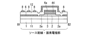
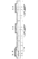
- 薄膜トランジスタを有する薄膜トランジスタアレイ基板であって、
基板上に形成された、前記薄膜トランジスタのゲート電極および前記ゲート電極に接続するゲート配線と、
前記ゲート電極および前記ゲート配線を覆うゲート絶縁膜と、
前記ゲート絶縁膜上に形成された半導体膜と、
前記ゲート電極の上方において、前記半導体膜上に形成された前記薄膜トランジスタのソース電極およびドレイン電極と、
前記ゲート絶縁膜上に形成され、前記ソース電極に接続するソース配線と、
前記ドレイン電極上に一部が直接重ねて形成された画素電極と、
前記ソース電極、前記ドレイン電極、前記ソース配線および前記画素電極を覆う層間絶縁膜と、
前記層間絶縁膜を介して前記画素電極に対向配置された対向電極とを備え、
前記半導体膜は、前記ドレイン電極、前記ソース電極および前記ソース配線それぞれの下、並びに、前記ソース電極とドレイン電極との間の領域に配設されており、
前記画素電極に隣接する前記ソース配線の下の前記半導体膜は、前記ソース配線の両側に1μm以上張り出している
ことを特徴とする薄膜トランジスタアレイ基板。 - 前記対向電極の一部は、前記ソース配線上を覆い、前記ソース配線を挟んで隣接する画素の対向電極と接続している
請求項1記載の薄膜トランジスタアレイ基板。 - 前記対向電極の一部は、前記ゲート電極上を覆い、前記ゲート配線を挟んで隣接する画素の対向電極と接続している
請求項1または請求項2記載の薄膜トランジスタアレイ基板。 - 前記ゲート配線と同じ層に形成された共通配線をさらに備え、
前記対向電極は、前記ゲート絶縁膜および前記層間絶縁膜を貫通するコンタクトホールを介して前記共通配線と電気的に接続する
請求項1から請求項3のいずれか一項記載の薄膜トランジスタアレイ基板。 - 前記ソース電極と前記半導体膜との間、前記ドレイン電極と前記半導体膜との間、および前記ソース配線と前記半導体膜との間のそれぞれに形成されたオーミックコンタクト膜をさらに有し、
前記ソース電極および前記ドレイン電極は、前記オーミックコンタクト膜を介して前記半導体膜が電気的に接続している
請求項1から請求項4のいずれか一項記載の薄膜トランジスタアレイ基板。 - 前記ソース電極、前記ドレイン電極および前記ソース配線は、AlまたはAlを主成分とする合金、もしくは、AgまたはAgを主成分とする合金により形成されている
請求項1から請求項5のいずれか一項記載の薄膜トランジスタアレイ基板。 - 請求項1から請求項6のいずれか一項記載の薄膜トランジスタアレイ基板を備える液晶表示装置。
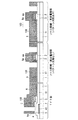
- 薄膜トランジスタを有する薄膜トランジスタアレイ基板の製造方法であって、
(a)基板上に第1の金属膜を成膜してパターニングすることで、前記薄膜トランジスタのゲート電極および前記ゲート電極に接続するゲート配線を形成する工程と、
(b)前記ゲート電極および前記ゲート配線を覆うゲート絶縁膜を形成する工程と、
(c)前記ゲート絶縁膜上に、半導体膜、オーミックコンタクト膜および第2の金属膜をこの順に成膜する工程と、
(d)前記半導体膜、前記オーミックコンタクト膜および前記第2の金属膜をパターニングして、前記薄膜トランジスタのチャネル領域となる領域上で互いに接続した状態のソース電極およびドレイン電極と、前記ソース電極に接続するソース配線とを形成する工程と、
(e)前記互いに接続した状態の前記ソース電極および前記ドレイン電極並びに前記ソース配線の上に、第1の透明導電膜を成膜する工程と、
(f)少なくとも前記チャネル領域となる領域上および前記画素電極に隣接する前記ソース配線のエッジ部を含む領域上が開口されたレジストパターンを用いるエッチングにより、前記第1の透明導電膜をパターニングして画素電極を形成すると共に、前記画素電極に隣接する前記ソース配線のエッジ部上の前記第1の透明導電膜を除去する工程と、
(g)前記工程(f)と同じレジストパターン、または前記工程(f)でパターニングされた前記第1の透明導電膜をマスクにして、前記第1の透明導電膜をパターニングしたことで露出した前記第2の金属膜をエッチングすることで、前記ソース電極および前記ドレイン電極とを分離すると共に、前記画素電極に隣接する前記ソース配線のエッジ部を除去する工程と、
(h)前記工程(f)と同じレジストパターン、または前記工程(f)でパターニングされた前記第1の透明導電膜をマスクにして、前記オーミックコンタクト膜を除去することで、前記チャネル領域となる領域および前記画素電極に隣接する前記ソース配線のエッジ部の下に位置していた前記半導体膜を露出させる工程と、
(i)前記画素電極、前記ソース配線および前記薄膜トランジスタを覆う層間絶縁膜を形成する工程と、
(j)前記層間絶縁膜上に、第2の透明導電膜を成膜してパターニングすることで、前記画素電極と対向する位置に対向電極を形成する工程と、
を備える
ることを特徴とする薄膜トランジスタアレイ基板の製造方法。 - 前記工程(d)で形成される前記ソース電極の幅と、前記工程(f)で形成される画素電極間の距離はほぼ同じである
請求項8記載の薄膜トランジスタアレイ基板の製造方法。 - 前記第2の金属膜は、AlまたはAlを主成分とする合金、もしくは、AgまたはAgを主成分とする合金により形成される
請求項8または請求項9記載の薄膜トランジスタアレイ基板の製造方法。 - 前記レジストパターンの形成後且つ前記第1の透明導電膜をパターニング前、または、前記レジストパターンの除去後且つ前記層間絶縁膜の形成前に、前記第2の金属膜の反射光を利用したパターン欠陥検査が行われる
請求項8から請求項10のいずれか一項記載の薄膜トランジスタアレイ基板の製造方法。 - 請求項8から請求項11のいずれか一項記載の薄膜トランジスタアレイ基板の製造方法を含む液晶表示装置の製造方法。
Priority Applications (2)
| Application Number | Priority Date | Filing Date | Title |
|---|---|---|---|
| JP2013155544A JP6278633B2 (ja) | 2013-07-26 | 2013-07-26 | 薄膜トランジスタアレイ基板およびその製造方法、並びに、液晶表示装置およびその製造方法 |
| US14/336,410 US9252161B2 (en) | 2013-07-26 | 2014-07-21 | Thin film transistor array substrate and manufacturing method thereof, and liquid crystal display device and manufacturing method thereof |
Applications Claiming Priority (1)
| Application Number | Priority Date | Filing Date | Title |
|---|---|---|---|
| JP2013155544A JP6278633B2 (ja) | 2013-07-26 | 2013-07-26 | 薄膜トランジスタアレイ基板およびその製造方法、並びに、液晶表示装置およびその製造方法 |
Publications (3)
| Publication Number | Publication Date |
|---|---|
| JP2015025955A JP2015025955A (ja) | 2015-02-05 |
| JP2015025955A5 JP2015025955A5 (ja) | 2016-09-08 |
| JP6278633B2 true JP6278633B2 (ja) | 2018-02-14 |
Family
ID=52389741
Family Applications (1)
| Application Number | Title | Priority Date | Filing Date |
|---|---|---|---|
| JP2013155544A Active JP6278633B2 (ja) | 2013-07-26 | 2013-07-26 | 薄膜トランジスタアレイ基板およびその製造方法、並びに、液晶表示装置およびその製造方法 |
Country Status (2)
| Country | Link |
|---|---|
| US (1) | US9252161B2 (ja) |
| JP (1) | JP6278633B2 (ja) |
Families Citing this family (9)
| Publication number | Priority date | Publication date | Assignee | Title |
|---|---|---|---|---|
| JP6315966B2 (ja) | 2013-12-11 | 2018-04-25 | 三菱電機株式会社 | アクティブマトリックス基板およびその製造方法 |
| JP6214019B2 (ja) * | 2014-03-07 | 2017-10-18 | 株式会社Joled | バンクの補修方法、有機el表示装置およびその製造方法 |
| CN104362152B (zh) * | 2014-09-16 | 2017-08-01 | 京东方科技集团股份有限公司 | 一种阵列基板的制备方法 |
| CN105223740B (zh) * | 2015-11-05 | 2019-01-22 | 深圳市华星光电技术有限公司 | 阵列基板及其制造方法、液晶显示面板 |
| CN109270754B (zh) * | 2017-07-17 | 2021-04-27 | 京东方科技集团股份有限公司 | 阵列基板和显示装置 |
| JP6978243B2 (ja) * | 2017-07-26 | 2021-12-08 | 三菱電機株式会社 | アレイ基板と当該アレイ基板を有する液晶表示装置 |
| JP2019184698A (ja) * | 2018-04-04 | 2019-10-24 | 三菱電機株式会社 | 液晶表示装置と当該液晶表示装置の製造方法 |
| WO2020174605A1 (ja) * | 2019-02-27 | 2020-09-03 | シャープ株式会社 | 表示装置及びその製造方法 |
| CN114023700B (zh) * | 2021-10-29 | 2022-11-01 | 惠州华星光电显示有限公司 | 一种tft基板的制作方法及tft基板 |
Family Cites Families (27)
| Publication number | Priority date | Publication date | Assignee | Title |
|---|---|---|---|---|
| JP3474309B2 (ja) * | 1995-03-24 | 2003-12-08 | 株式会社半導体エネルギー研究所 | アクティブマトリクス型の液晶表示装置の作製方法 |
| JP4004835B2 (ja) * | 2002-04-02 | 2007-11-07 | 株式会社アドバンスト・ディスプレイ | 薄膜トランジスタアレイ基板の製造方法 |
| KR20060069081A (ko) * | 2004-12-17 | 2006-06-21 | 삼성전자주식회사 | 박막 트랜지스터 표시판 및 그의 제조 방법 |
| KR101085450B1 (ko) * | 2005-02-07 | 2011-11-21 | 삼성전자주식회사 | 박막트랜지스터 기판과 그 제조방법 |
| KR20070019457A (ko) * | 2005-08-12 | 2007-02-15 | 삼성전자주식회사 | 박막 트랜지스터 표시판 및 이를 포함하는 액정표시장치 |
| JP2007102225A (ja) * | 2005-10-05 | 2007-04-19 | Samsung Electronics Co Ltd | 薄膜トランジスタ表示板及びその製造方法 |
| KR100818887B1 (ko) * | 2005-12-14 | 2008-04-02 | 엘지.필립스 엘시디 주식회사 | 액정 표시장치 및 그 제조 방법 |
| KR101192750B1 (ko) * | 2005-12-30 | 2012-10-18 | 엘지디스플레이 주식회사 | Tft 어레이 기판 및 그 제조방법 |
| KR20080001181A (ko) * | 2006-06-29 | 2008-01-03 | 엘지.필립스 엘시디 주식회사 | 액정표시장치용 어레이 기판과 그 제조방법 |
| KR101284697B1 (ko) * | 2006-06-30 | 2013-07-23 | 엘지디스플레이 주식회사 | 액정표시장치용 어레이 기판과 그 제조방법 |
| JP5081444B2 (ja) * | 2006-12-21 | 2012-11-28 | 株式会社ジャパンディスプレイイースト | 表示装置 |
| KR101373735B1 (ko) * | 2007-02-22 | 2014-03-14 | 삼성디스플레이 주식회사 | 신호선의 제조 방법, 박막 트랜지스터 표시판 및 그의 제조방법 |
| JP4374552B2 (ja) * | 2007-04-12 | 2009-12-02 | ソニー株式会社 | 基板の製造方法および基板製造システム、並びに表示装置の製造方法 |
| KR101294232B1 (ko) * | 2007-06-08 | 2013-08-07 | 엘지디스플레이 주식회사 | 프린지 필드 스위칭 모드 액정표시장치용 어레이 기판 및이의 제조 방법 |
| JP5456980B2 (ja) * | 2008-02-15 | 2014-04-02 | 三菱電機株式会社 | 液晶表示装置、及びその製造方法 |
| JP5409024B2 (ja) * | 2008-02-15 | 2014-02-05 | 株式会社半導体エネルギー研究所 | 表示装置 |
| JP5113609B2 (ja) * | 2008-04-24 | 2013-01-09 | パナソニック液晶ディスプレイ株式会社 | 表示装置及びその製造方法 |
| JP2009288462A (ja) * | 2008-05-28 | 2009-12-10 | Ips Alpha Technology Ltd | 表示装置及びその製造方法 |
| DE102008058709B4 (de) * | 2008-06-25 | 2014-06-26 | Lg Display Co., Ltd. | Arraysubstrat für Fringe-Field-Schaltmodus-Flüssigkristallanzeigevorrichtung und eine Fringe-Field-Schaltmodus-Flüssigkristallanzeigevorrichtung, die dasselbe aufweist |
| KR101499239B1 (ko) * | 2008-08-26 | 2015-03-06 | 삼성디스플레이 주식회사 | 박막 트랜지스터 표시판 및 그 제조 방법 |
| JP5646162B2 (ja) * | 2009-01-23 | 2014-12-24 | 三菱電機株式会社 | 薄膜トランジスタアレイ基板、その製造方法、及び液晶表示装置 |
| KR20120060664A (ko) * | 2010-12-02 | 2012-06-12 | 삼성전자주식회사 | 표시 장치 및 표시 장치 제조 방법 |
| JP5907697B2 (ja) * | 2011-11-09 | 2016-04-26 | 三菱電機株式会社 | 配線構造及びそれを備える薄膜トランジスタアレイ基板並びに表示装置 |
| TWI489560B (zh) * | 2011-11-24 | 2015-06-21 | Au Optronics Corp | 畫素結構及其製作方法 |
| JP5286438B2 (ja) * | 2012-10-18 | 2013-09-11 | 三菱電機株式会社 | 液晶表示装置 |
| JP6238712B2 (ja) * | 2013-12-05 | 2017-11-29 | 三菱電機株式会社 | 薄膜トランジスタ基板およびその製造方法 |
| JP6315966B2 (ja) * | 2013-12-11 | 2018-04-25 | 三菱電機株式会社 | アクティブマトリックス基板およびその製造方法 |
-
2013
- 2013-07-26 JP JP2013155544A patent/JP6278633B2/ja active Active
-
2014
- 2014-07-21 US US14/336,410 patent/US9252161B2/en active Active
Also Published As
| Publication number | Publication date |
|---|---|
| US9252161B2 (en) | 2016-02-02 |
| US20150028340A1 (en) | 2015-01-29 |
| JP2015025955A (ja) | 2015-02-05 |
Similar Documents
| Publication | Publication Date | Title |
|---|---|---|
| JP6278633B2 (ja) | 薄膜トランジスタアレイ基板およびその製造方法、並びに、液晶表示装置およびその製造方法 | |
| KR101108943B1 (ko) | 박막 트랜지스터 어레이 기판, 그 제조방법, 및 액정표시장치 | |
| TWI415239B (zh) | Liquid crystal display panel, manufacturing method thereof, and array substrate and manufacturing method thereof | |
| JP2006317516A (ja) | 液晶表示装置及びその製造方法 | |
| JP2006189830A (ja) | 液晶表示装置およびその製造方法 | |
| JP5863399B2 (ja) | 配線構造及びそれを備える薄膜トランジスタアレイ基板並びに表示装置 | |
| JP5117893B2 (ja) | 液晶表示装置、及びその製造方法 | |
| US20130334534A1 (en) | Liquid crystal display and method of manufacturing the same | |
| US7300828B2 (en) | Method of manufacturing a liquid crystal display device | |
| JP4299025B2 (ja) | 液晶表示装置 | |
| JP6112886B2 (ja) | 薄膜トランジスタアレイ基板およびその製造方法 | |
| JP2005182048A (ja) | 多重ドメイン薄膜トランジスタ表示板及びこれを含む液晶表示装置 | |
| JP4112672B2 (ja) | 表示装置用アレイ基板及びその製造方法 | |
| JP2012151382A (ja) | 薄膜トランジスタ、アクティブマトリクス基板、およびそれらの製造方法 | |
| KR20070036915A (ko) | 박막 트랜지스터 기판, 액정 표시 장치 및 그 제조 방법 | |
| US10466526B2 (en) | Liquid crystal display device and method for manufacturing TFT array substrate | |
| KR20090070234A (ko) | 액정표시패널과 이의 제조방법 및 이를 이용한 리페어 방법 | |
| JP6425676B2 (ja) | 表示装置の製造方法 | |
| JP5286438B2 (ja) | 液晶表示装置 | |
| JP6234232B2 (ja) | 液晶表示パネルおよびそのリペア方法 | |
| US20190310506A1 (en) | Liquid crystal display apparatus and method for manufacturing liquid crystal display apparatus | |
| KR20040057785A (ko) | 액정표시장치 | |
| KR101030530B1 (ko) | 액정표시장치 및 그 제조방법 | |
| JP2008065214A (ja) | 液晶装置の製造方法 | |
| JP6497056B2 (ja) | 液晶表示装置の製造方法 |
Legal Events
| Date | Code | Title | Description |
|---|---|---|---|
| A521 | Request for written amendment filed |
Free format text: JAPANESE INTERMEDIATE CODE: A523 Effective date: 20160721 |
|
| A621 | Written request for application examination |
Free format text: JAPANESE INTERMEDIATE CODE: A621 Effective date: 20160721 |
|
| A977 | Report on retrieval |
Free format text: JAPANESE INTERMEDIATE CODE: A971007 Effective date: 20170519 |
|
| A131 | Notification of reasons for refusal |
Free format text: JAPANESE INTERMEDIATE CODE: A131 Effective date: 20170530 |
|
| A521 | Request for written amendment filed |
Free format text: JAPANESE INTERMEDIATE CODE: A523 Effective date: 20170724 |
|
| TRDD | Decision of grant or rejection written | ||
| A01 | Written decision to grant a patent or to grant a registration (utility model) |
Free format text: JAPANESE INTERMEDIATE CODE: A01 Effective date: 20171219 |
|
| A61 | First payment of annual fees (during grant procedure) |
Free format text: JAPANESE INTERMEDIATE CODE: A61 Effective date: 20180116 |
|
| R150 | Certificate of patent or registration of utility model |
Ref document number: 6278633 Country of ref document: JP Free format text: JAPANESE INTERMEDIATE CODE: R150 |
|
| R250 | Receipt of annual fees |
Free format text: JAPANESE INTERMEDIATE CODE: R250 |
|
| R250 | Receipt of annual fees |
Free format text: JAPANESE INTERMEDIATE CODE: R250 |
|
| R250 | Receipt of annual fees |
Free format text: JAPANESE INTERMEDIATE CODE: R250 |
|
| R250 | Receipt of annual fees |
Free format text: JAPANESE INTERMEDIATE CODE: R250 |