JP2010096926A - 光走査装置および画像形成装置 - Google Patents
光走査装置および画像形成装置 Download PDFInfo
- Publication number
- JP2010096926A JP2010096926A JP2008266817A JP2008266817A JP2010096926A JP 2010096926 A JP2010096926 A JP 2010096926A JP 2008266817 A JP2008266817 A JP 2008266817A JP 2008266817 A JP2008266817 A JP 2008266817A JP 2010096926 A JP2010096926 A JP 2010096926A
- Authority
- JP
- Japan
- Prior art keywords
- main scanning
- scanning
- scanning position
- main
- scanned
- Prior art date
- Legal status (The legal status is an assumption and is not a legal conclusion. Google has not performed a legal analysis and makes no representation as to the accuracy of the status listed.)
- Granted
Links
Images


Classifications
-
- H—ELECTRICITY
- H04—ELECTRIC COMMUNICATION TECHNIQUE
- H04N—PICTORIAL COMMUNICATION, e.g. TELEVISION
- H04N1/00—Scanning, transmission or reproduction of documents or the like, e.g. facsimile transmission; Details thereof
- H04N1/04—Scanning arrangements, i.e. arrangements for the displacement of active reading or reproducing elements relative to the original or reproducing medium, or vice versa
- H04N1/047—Detection, control or error compensation of scanning velocity or position
- H04N1/053—Detection, control or error compensation of scanning velocity or position in main scanning direction, e.g. synchronisation of line start or picture elements in a line
-
- H—ELECTRICITY
- H04—ELECTRIC COMMUNICATION TECHNIQUE
- H04N—PICTORIAL COMMUNICATION, e.g. TELEVISION
- H04N1/00—Scanning, transmission or reproduction of documents or the like, e.g. facsimile transmission; Details thereof
- H04N1/04—Scanning arrangements, i.e. arrangements for the displacement of active reading or reproducing elements relative to the original or reproducing medium, or vice versa
- H04N1/113—Scanning arrangements, i.e. arrangements for the displacement of active reading or reproducing elements relative to the original or reproducing medium, or vice versa using oscillating or rotating mirrors
- H04N1/1135—Scanning arrangements, i.e. arrangements for the displacement of active reading or reproducing elements relative to the original or reproducing medium, or vice versa using oscillating or rotating mirrors for the main-scan only
-
- H—ELECTRICITY
- H04—ELECTRIC COMMUNICATION TECHNIQUE
- H04N—PICTORIAL COMMUNICATION, e.g. TELEVISION
- H04N1/00—Scanning, transmission or reproduction of documents or the like, e.g. facsimile transmission; Details thereof
- H04N1/04—Scanning arrangements, i.e. arrangements for the displacement of active reading or reproducing elements relative to the original or reproducing medium, or vice versa
- H04N1/12—Scanning arrangements, i.e. arrangements for the displacement of active reading or reproducing elements relative to the original or reproducing medium, or vice versa using the sheet-feed movement or the medium-advance or the drum-rotation movement as the slow scanning component, e.g. arrangements for the main-scanning
-
- H—ELECTRICITY
- H04—ELECTRIC COMMUNICATION TECHNIQUE
- H04N—PICTORIAL COMMUNICATION, e.g. TELEVISION
- H04N2201/00—Indexing scheme relating to scanning, transmission or reproduction of documents or the like, and to details thereof
- H04N2201/0077—Types of the still picture apparatus
- H04N2201/0082—Image hardcopy reproducer
-
- H—ELECTRICITY
- H04—ELECTRIC COMMUNICATION TECHNIQUE
- H04N—PICTORIAL COMMUNICATION, e.g. TELEVISION
- H04N2201/00—Indexing scheme relating to scanning, transmission or reproduction of documents or the like, and to details thereof
- H04N2201/024—Indexing scheme relating to scanning, transmission or reproduction of documents or the like, and to details thereof deleted
- H04N2201/02406—Arrangements for positioning elements within a head
- H04N2201/02439—Positioning method
- H04N2201/02443—Positioning method using adhesive
-
- H—ELECTRICITY
- H04—ELECTRIC COMMUNICATION TECHNIQUE
- H04N—PICTORIAL COMMUNICATION, e.g. TELEVISION
- H04N2201/00—Indexing scheme relating to scanning, transmission or reproduction of documents or the like, and to details thereof
- H04N2201/04—Scanning arrangements
- H04N2201/047—Detection, control or error compensation of scanning velocity or position
- H04N2201/04701—Detection of scanning velocity or position
- H04N2201/0471—Detection of scanning velocity or position using dedicated detectors
-
- H—ELECTRICITY
- H04—ELECTRIC COMMUNICATION TECHNIQUE
- H04N—PICTORIAL COMMUNICATION, e.g. TELEVISION
- H04N2201/00—Indexing scheme relating to scanning, transmission or reproduction of documents or the like, and to details thereof
- H04N2201/04—Scanning arrangements
- H04N2201/047—Detection, control or error compensation of scanning velocity or position
- H04N2201/04701—Detection of scanning velocity or position
- H04N2201/04732—Detecting at infrequent intervals, e.g. once or twice per line for main-scan control
-
- H—ELECTRICITY
- H04—ELECTRIC COMMUNICATION TECHNIQUE
- H04N—PICTORIAL COMMUNICATION, e.g. TELEVISION
- H04N2201/00—Indexing scheme relating to scanning, transmission or reproduction of documents or the like, and to details thereof
- H04N2201/04—Scanning arrangements
- H04N2201/047—Detection, control or error compensation of scanning velocity or position
- H04N2201/04701—Detection of scanning velocity or position
- H04N2201/04744—Detection of scanning velocity or position by detecting the scanned beam or a reference beam
-
- H—ELECTRICITY
- H04—ELECTRIC COMMUNICATION TECHNIQUE
- H04N—PICTORIAL COMMUNICATION, e.g. TELEVISION
- H04N2201/00—Indexing scheme relating to scanning, transmission or reproduction of documents or the like, and to details thereof
- H04N2201/04—Scanning arrangements
- H04N2201/047—Detection, control or error compensation of scanning velocity or position
- H04N2201/04753—Control or error compensation of scanning position or velocity
- H04N2201/04758—Control or error compensation of scanning position or velocity by controlling the position of the scanned image area
- H04N2201/04767—Control or error compensation of scanning position or velocity by controlling the position of the scanned image area by controlling the timing of the signals, e.g. by controlling the frequency o phase of the pixel clock
- H04N2201/04768—Controlling the frequency of the signals
- H04N2201/04775—Controlling the frequency of the signals using a counter
-
- H—ELECTRICITY
- H04—ELECTRIC COMMUNICATION TECHNIQUE
- H04N—PICTORIAL COMMUNICATION, e.g. TELEVISION
- H04N2201/00—Indexing scheme relating to scanning, transmission or reproduction of documents or the like, and to details thereof
- H04N2201/04—Scanning arrangements
- H04N2201/047—Detection, control or error compensation of scanning velocity or position
- H04N2201/04753—Control or error compensation of scanning position or velocity
- H04N2201/04794—Varying the control or compensation during the scan, e.g. using continuous feedback or from line to line
- H04N2201/04798—Varying the main-scan control during the main-scan, e.g. facet tracking
Abstract
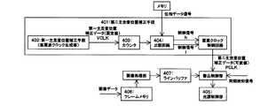
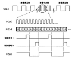
【解決手段】正弦振動して光源からの光束を偏向走査する偏向手段106、偏向された光束により走査される被走査面、被走査面を主走査方向に第一の分割数で分割し、第一分割数による分割領域毎にクロックパルスのタイミングを個別に設定して、主走査位置誤差を補正する第一主走査位置補正手段402、第一主走査位置補正データを元に、被走査面を主走査方向に第二の分割数で分割し、第二分割数による分割領域毎にクロックパルスのタイミングを個別に設定して、主走査位置誤差を補正する第二主走査位置補正手段401を備える。
【選択図】図2
Description
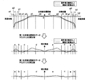
振動ミラーは共振現象を用いており正弦波的に振動するので、各像高で走査速度が異なり、主走査方向のドット位置を調整することが必須となる。そのため、以下のような主走査方向ドット位置補正を同時に行っている。図10は、振動ミラーを単一の周波数の信号で駆動したときの主走査方向に応じた各画素における主走査位置の補正量を示す。主走査領域を複数の領域、実施例では主走査領域を8つの領域に分割し、折れ線で近似することで各領域の境界で主走査位置ずれが0となるように、領域毎に位相シフト回数を設定し、階段状に補正するようになっている。
ni=Ni/(ΔLi/(p/8))
となり、ni画素毎に位相をシフトしてやればよい。
画素クロックをfcとすると、トータルでの位相差Δtは、位相シフト回数Ni/niを用い
Δt=1/16fc×∫(Ni/ni)di
となり、Nドット目の画素における位相差についても同様に、それまでの位相シフトの累積回数により設定できる。
振動ミラーは、単体の走査特性の経時変動が大きいという課題もある。
第二主走査位置補正手段にのみ可変テーブルを持たせることで、可変テーブルのメモリを少なくし、コストの増大を防ぐことができる。
第二の分割数を少なく設定することで、その分割数分の可変テーブルのメモリを少なくし、コストの増大を防ぐことができる。
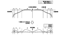
マイクロミラー特有の被走査面中央で走査速度が最速になる走査特性を補正するように第一主走査位置補正手段を設定することができる。
実際には設計値である破線で示す特性に加え、製造誤差などに起因する変動が合わさって、実線で示す曲線のように、高次成分を含んだ主走査位置誤差特性となる。
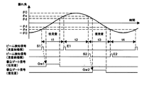
θ=θ0・sin(2πfd・t/2) fd:振動ミラーの駆動周波数
で表され、θ=θsのときの時間を検出すれば、θsは一定であるから振幅θ0を算出することができる。
マイクロミラーの走査特性を電気的に補正し、走査レンズにfθレンズを用いることで、主走査ビームスポット径を被走査面全域にわたり均一に設定し、良好な走査特性を得ることができる。
マイクロミラー単体の走査特性を制御することにより、主走査位置誤差を初期に補正した状態で、経時的にも主走査位置誤差のない走査特性を得ることができる。
複数の検知手段からの信号に基づき走査特性を制御することで、より精度良く光偏向器の走査特性を制御することができる。
画像書込のタイミングをリアルタイムで検知することにより、経時的な変動もなくタイミングを精度良く制御できる。また、偏向器制御と画像書込タイミング制御の検知手段を兼ねることにより、低コストで光走査装置を構成することができる。
往復走査にて画像書込を行う際にも精度良く画像書込タイミング制御を行うことができる。また、偏向器制御と画像書込タイミング制御の検知手段を兼ねることにより、低コストで光走査装置を構成することができる。
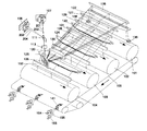
106 振動ミラー(偏向手段)
107、108 光源ユニット
120 第1走査レンズ
126 第2走査レンズ
401 第二主走査位置補正手段
402 第一主走査位置補正手段
Claims (13)
- 光源と、
正弦振動することにより前記光源から射出された光束を偏向走査する偏向手段と、
前記偏向手段により偏向された光束により走査される被走査面と、
前記被走査面を主走査方向に第一の分割数で分割し、この第一分割数による分割領域毎にクロックパルスのタイミングを個別に設定して、主走査位置誤差を補正する第一主走査位置補正手段と、
前記第一主走査位置補正手段によって補正された第一主走査位置補正データを元に、前記被走査面を主走査方向に第二の分割数で分割し、この第二分割数による分割領域毎にクロックパルスのタイミングを個別に設定して、主走査位置誤差を補正する第二主走査位置補正手段と、を備え、
前記第一主走査位置補正手段によって補正された第一主走査位置補正データを元に、第二主走査位置補正手段とによって主走査位置の補正を行うことを特徴とする光走査装置。 - 前記第一主走査位置補正手段により第一分割数で分割された分割領域毎にクロック周波数を決定し、このクロック周波数に基づいて前記第二主走査位置補正手段により主走査位置誤差を補正することを特徴とする請求項1記載の光走査装置。
- 主走査位置誤差の二次成分を、前記第一主走査位置補正手段により、高次成分を第二主走査位置補正手段によりそれぞれ補正することを特徴とする請求項1または2記載の光走査装置。
- 前記第二主走査位置補正手段にのみ可変テーブルを有することを特徴とする請求項1または3記載の光走査装置。
- 前記第二主走査位置補正手段による分割数は前記第一主走査位置補正手段による分割数よりも少ないことを特徴とする請求項1ないし4のいずれかに記載の光走査装置。
- 前記第一主走査位置補正手段は、前記被走査面中央部よりも周辺部で、前記光源を駆動する光源駆動周波数を低く設定することを特徴とする請求項1ないし5のいずれかに記載の光走査装置。
- 前記光偏向器により偏向された光束を前記被走査面に結像走査させる結像手段をさらに有し、この結像手段はfθ特性を有することを特徴とする請求項1ないし6のいずれかに記載の光走査装置。
- 前記偏向器の走査特性を経時的に一定に保つ走査特性制御手段をさらに有することを特徴とする請求項1ないし7のいずれかに記載の光走査装置。
- 前記走査特性制御手段は、前記偏向器の振幅、振幅中央、位相を制御することを特徴とする請求項8記載の光走査装置。
- 走査位置を検知する検知手段を複数備え、複数の検知手段から得られる検知信号を前記走査特性制御手段に入力することを特徴とする請求項8または9記載の光走査装置
- 複数の前記検知手段からの検知信号のうち、一の検知信号を画像書込のタイミングを決定する水平同期信号として、前記被走査面に往路もしくは復路のみで画像を書き込むことを特徴とする請求項10記載の光走査装置。
- 複数の前記検知手段からの検知信号のうち、画像書込直前の検知信号を画像書込のタイミングを決定する水平同期信号として、前記被走査面に往復走査で画像を書き込むことを特徴とする請求項10記載の光走査装置。
- 電子写真プロセスを実行するための各プロセスユニットを備えた画像形成装置であって、電子写真プロセス中の露光プロセスを実行するユニットとして請求項1ないし12のいずれかに記載の光走査装置を備えている画像形成装置。
Priority Applications (2)
| Application Number | Priority Date | Filing Date | Title |
|---|---|---|---|
| JP2008266817A JP5078836B2 (ja) | 2008-10-15 | 2008-10-15 | 光走査装置および画像形成装置 |
| US12/563,214 US8314975B2 (en) | 2008-10-15 | 2009-09-21 | Optical scanning device and image forming apparatus |
Applications Claiming Priority (1)
| Application Number | Priority Date | Filing Date | Title |
|---|---|---|---|
| JP2008266817A JP5078836B2 (ja) | 2008-10-15 | 2008-10-15 | 光走査装置および画像形成装置 |
Publications (2)
| Publication Number | Publication Date |
|---|---|
| JP2010096926A true JP2010096926A (ja) | 2010-04-30 |
| JP5078836B2 JP5078836B2 (ja) | 2012-11-21 |
Family
ID=42098600
Family Applications (1)
| Application Number | Title | Priority Date | Filing Date |
|---|---|---|---|
| JP2008266817A Expired - Fee Related JP5078836B2 (ja) | 2008-10-15 | 2008-10-15 | 光走査装置および画像形成装置 |
Country Status (2)
| Country | Link |
|---|---|
| US (1) | US8314975B2 (ja) |
| JP (1) | JP5078836B2 (ja) |
Families Citing this family (11)
| Publication number | Priority date | Publication date | Assignee | Title |
|---|---|---|---|---|
| US8593701B2 (en) * | 2009-09-04 | 2013-11-26 | Ricoh Company, Ltd. | Optical scanning device and image forming apparatus |
| JP2011100007A (ja) * | 2009-11-06 | 2011-05-19 | Ricoh Co Ltd | 光走査装置および画像形成装置 |
| JP5505617B2 (ja) | 2009-12-10 | 2014-05-28 | 株式会社リコー | 光走査装置及び画像形成装置 |
| JP5691528B2 (ja) | 2011-01-07 | 2015-04-01 | 株式会社リコー | 光走査装置及び画像形成装置 |
| JP5761655B2 (ja) | 2011-03-16 | 2015-08-12 | 株式会社リコー | 光走査装置、画像形成装置、走査レンズ及び走査レンズの成形方法 |
| JP5945894B2 (ja) | 2011-07-11 | 2016-07-05 | 株式会社リコー | 光走査装置及び画像形成装置 |
| JP6065556B2 (ja) * | 2011-12-19 | 2017-01-25 | 株式会社リコー | 画像形成装置、画像形成装置の調整方法、画像形成装置の生産方法、及び画像形成システム |
| JP2013178496A (ja) | 2012-02-06 | 2013-09-09 | Ricoh Co Ltd | 光走査装置及び画像形成装置 |
| JP5935404B2 (ja) | 2012-03-08 | 2016-06-15 | 株式会社リコー | 光走査装置および画像形成装置 |
| JP2017016006A (ja) | 2015-07-03 | 2017-01-19 | 株式会社リコー | 光走査装置、画像表示装置 |
| JP6657897B2 (ja) | 2015-12-10 | 2020-03-04 | 株式会社リコー | ミラー部材の加工方法 |
Citations (7)
| Publication number | Priority date | Publication date | Assignee | Title |
|---|---|---|---|---|
| JPH02131212A (ja) * | 1988-11-11 | 1990-05-21 | Minolta Camera Co Ltd | レーザビームの走査速度補正方式 |
| JP2003276235A (ja) * | 2002-03-20 | 2003-09-30 | Fuji Xerox Co Ltd | 画像形成装置 |
| JP2006259444A (ja) * | 2005-03-18 | 2006-09-28 | Ricoh Co Ltd | 多色画像形成装置および色ずれ補正方法 |
| JP2007033876A (ja) * | 2005-07-27 | 2007-02-08 | Ricoh Co Ltd | 光走査装置及び画像形成装置 |
| JP2007086496A (ja) * | 2005-09-22 | 2007-04-05 | Ricoh Co Ltd | 光走査装置および画像形成装置 |
| JP2007233235A (ja) * | 2006-03-03 | 2007-09-13 | Ricoh Co Ltd | 光走査装置および画像形成装置 |
| JP2008191010A (ja) * | 2007-02-05 | 2008-08-21 | Ricoh Co Ltd | ビームプロファイル計測装置・光走査装置・画像形成装置 |
Family Cites Families (24)
| Publication number | Priority date | Publication date | Assignee | Title |
|---|---|---|---|---|
| US4848879A (en) * | 1982-10-09 | 1989-07-18 | Canon Kabushiki Kaisha | Light modulating device |
| US4902084A (en) * | 1988-07-29 | 1990-02-20 | Oren Aharon | Optical scanning system |
| JPH03270567A (ja) * | 1990-03-20 | 1991-12-02 | Fuji Photo Film Co Ltd | 画像信号補正方法 |
| US5255108A (en) * | 1992-04-27 | 1993-10-19 | Eastman Kodak Company | Method of maximizing the frequency of adjacent facet cross scan error such that the increased spatial frequency reduces the visual perception of the exposure error |
| JP3447907B2 (ja) * | 1996-02-07 | 2003-09-16 | 富士通株式会社 | 画像形成装置 |
| US5999302A (en) * | 1997-06-27 | 1999-12-07 | Speedring Systems, Inc. | Polygon scanner having a fluid film bearing and active correction of cross-scan and in-scan errors |
| US6625331B1 (en) * | 1998-07-03 | 2003-09-23 | Minolta Co., Ltd. | Image forming apparatus |
| JP3668022B2 (ja) * | 1998-11-16 | 2005-07-06 | 株式会社リコー | 画像形成装置 |
| US6930810B1 (en) * | 2000-11-28 | 2005-08-16 | Kabushiki Kaisha Toshiba | Correction table forming method and image forming apparatus |
| JP4598286B2 (ja) | 2001-03-02 | 2010-12-15 | 株式会社リコー | 光走査装置及び画像形成装置 |
| JP3738758B2 (ja) * | 2002-09-30 | 2006-01-25 | ブラザー工業株式会社 | 画像形成装置 |
| US7379085B2 (en) * | 2005-05-26 | 2008-05-27 | Xerox Corporation | System and method for reducing non-linearity errors between two imaging stations |
| JP5027999B2 (ja) * | 2005-07-08 | 2012-09-19 | キヤノン株式会社 | 記録装置およびその制御方法 |
| JP2007086335A (ja) | 2005-09-21 | 2007-04-05 | Fuji Xerox Co Ltd | 光走査装置 |
| JP4909653B2 (ja) | 2006-06-21 | 2012-04-04 | 株式会社リコー | 光走査装置及び画像形成装置 |
| JP4921896B2 (ja) | 2006-09-01 | 2012-04-25 | 株式会社リコー | 光走査装置及び画像形成装置 |
| US7729031B2 (en) | 2006-09-07 | 2010-06-01 | Ricoh Company, Ltd. | Light-source device, optical scanning device, and image forming apparatus |
| US7782511B2 (en) * | 2006-12-28 | 2010-08-24 | Canon Kabushiki Kaisha | Optical scanning apparatus and image forming apparatus comprising the same |
| JP5228331B2 (ja) | 2007-02-13 | 2013-07-03 | 株式会社リコー | 光走査装置、画像形成装置、および多色対応の画像形成装置 |
| JP4836267B2 (ja) | 2007-02-22 | 2011-12-14 | 株式会社リコー | 光走査装置及び画像形成装置 |
| JP4965284B2 (ja) | 2007-03-07 | 2012-07-04 | 株式会社リコー | 光走査装置・画像形成装置 |
| US7869110B2 (en) | 2007-07-11 | 2011-01-11 | Ricoh Company, Ltd. | Optical scan apparatus and image formation apparatus |
| JP2009069504A (ja) | 2007-09-13 | 2009-04-02 | Ricoh Co Ltd | 光走査装置、および画像形成装置 |
| JP2009192563A (ja) | 2008-02-12 | 2009-08-27 | Ricoh Co Ltd | 光走査装置及び画像形成装置 |
-
2008
- 2008-10-15 JP JP2008266817A patent/JP5078836B2/ja not_active Expired - Fee Related
-
2009
- 2009-09-21 US US12/563,214 patent/US8314975B2/en not_active Expired - Fee Related
Patent Citations (7)
| Publication number | Priority date | Publication date | Assignee | Title |
|---|---|---|---|---|
| JPH02131212A (ja) * | 1988-11-11 | 1990-05-21 | Minolta Camera Co Ltd | レーザビームの走査速度補正方式 |
| JP2003276235A (ja) * | 2002-03-20 | 2003-09-30 | Fuji Xerox Co Ltd | 画像形成装置 |
| JP2006259444A (ja) * | 2005-03-18 | 2006-09-28 | Ricoh Co Ltd | 多色画像形成装置および色ずれ補正方法 |
| JP2007033876A (ja) * | 2005-07-27 | 2007-02-08 | Ricoh Co Ltd | 光走査装置及び画像形成装置 |
| JP2007086496A (ja) * | 2005-09-22 | 2007-04-05 | Ricoh Co Ltd | 光走査装置および画像形成装置 |
| JP2007233235A (ja) * | 2006-03-03 | 2007-09-13 | Ricoh Co Ltd | 光走査装置および画像形成装置 |
| JP2008191010A (ja) * | 2007-02-05 | 2008-08-21 | Ricoh Co Ltd | ビームプロファイル計測装置・光走査装置・画像形成装置 |
Also Published As
| Publication number | Publication date |
|---|---|
| US8314975B2 (en) | 2012-11-20 |
| JP5078836B2 (ja) | 2012-11-21 |
| US20100091342A1 (en) | 2010-04-15 |
Similar Documents
| Publication | Publication Date | Title |
|---|---|---|
| JP5078836B2 (ja) | 光走査装置および画像形成装置 | |
| JP4912071B2 (ja) | 光走査装置、光走査方法、画像形成装置、カラー画像形成装置、プログラム、記録媒体 | |
| JP4863840B2 (ja) | 画素形成装置、光走査装置、光走査方法、画像形成装置、カラー画像形成装置 | |
| JP4341908B2 (ja) | 画素クロック及びパルス変調信号生成装置、光走査装置並びに画像形成装置 | |
| US7391003B2 (en) | Apparatus and method for adjusting write start position of a scanning light beam of an image forming apparatus | |
| JP2007269001A (ja) | 光走査装置、光走査方法、画像形成装置、カラー画像形成装置、プログラム、記録媒体 | |
| JP2005231325A (ja) | 画素クロック生成装置、光走査装置及び画像形成装置 | |
| JP2013117699A (ja) | 画像形成装置 | |
| JP2004050515A (ja) | 画像形成装置 | |
| JP2011064765A (ja) | 光ビーム走査光学装置 | |
| JP2003185953A (ja) | 光走査装置およびこれを用いた画像形成装置 | |
| JP4896663B2 (ja) | 画素形成装置、光走査装置、光走査方法、画像形成装置、カラー画像形成装置、プログラム、記録媒体 | |
| JP4134999B2 (ja) | 発光タイミング調整方法、レーザ走査装置及び画像形成装置 | |
| JP4313224B2 (ja) | ドット位置補正方法及びそれを適用した画像形成装置 | |
| JP5445250B2 (ja) | 画像形成装置および画像形成方法 | |
| JP4455084B2 (ja) | 画像形成装置 | |
| US11973914B2 (en) | Image forming apparatus configured to perform halftone processing | |
| US20060221172A1 (en) | Light beam scanning apparatus and image forming apparatus | |
| JP2004212873A (ja) | 光走査装置及び画像形成装置 | |
| JP2006305879A (ja) | 画像形成装置及び画像形成方法 | |
| JP2006116716A (ja) | 光走査装置、光走査装置の画素クロック生成方法および画像形成装置 | |
| JP2007249104A (ja) | 光走査装置、画像形成装置、カラー画像形成装置 | |
| JP2018001588A (ja) | 画像形成装置 | |
| JP2004102103A (ja) | 画像形成装置およびその走査長制御方法 | |
| JP4866057B2 (ja) | 光学装置、画像形成装置、点灯位置変更方法 |
Legal Events
| Date | Code | Title | Description |
|---|---|---|---|
| A621 | Written request for application examination |
Free format text: JAPANESE INTERMEDIATE CODE: A621 Effective date: 20110812 |
|
| A977 | Report on retrieval |
Free format text: JAPANESE INTERMEDIATE CODE: A971007 Effective date: 20120814 |
|
| TRDD | Decision of grant or rejection written | ||
| A01 | Written decision to grant a patent or to grant a registration (utility model) |
Free format text: JAPANESE INTERMEDIATE CODE: A01 Effective date: 20120821 |
|
| A01 | Written decision to grant a patent or to grant a registration (utility model) |
Free format text: JAPANESE INTERMEDIATE CODE: A01 |
|
| A61 | First payment of annual fees (during grant procedure) |
Free format text: JAPANESE INTERMEDIATE CODE: A61 Effective date: 20120828 |
|
| FPAY | Renewal fee payment (event date is renewal date of database) |
Free format text: PAYMENT UNTIL: 20150907 Year of fee payment: 3 |
|
| R150 | Certificate of patent or registration of utility model |
Ref document number: 5078836 Country of ref document: JP Free format text: JAPANESE INTERMEDIATE CODE: R150 Free format text: JAPANESE INTERMEDIATE CODE: R150 |
|
| LAPS | Cancellation because of no payment of annual fees |