JP2010004365A - 原稿照明装置、画像読取装置および画像形成装置 - Google Patents
原稿照明装置、画像読取装置および画像形成装置 Download PDFInfo
- Publication number
- JP2010004365A JP2010004365A JP2008162025A JP2008162025A JP2010004365A JP 2010004365 A JP2010004365 A JP 2010004365A JP 2008162025 A JP2008162025 A JP 2008162025A JP 2008162025 A JP2008162025 A JP 2008162025A JP 2010004365 A JP2010004365 A JP 2010004365A
- Authority
- JP
- Japan
- Prior art keywords
- document
- light
- unit
- scanning direction
- image
- Prior art date
- Legal status (The legal status is an assumption and is not a legal conclusion. Google has not performed a legal analysis and makes no representation as to the accuracy of the status listed.)
- Granted
Links
Images


Classifications
-
- H—ELECTRICITY
- H04—ELECTRIC COMMUNICATION TECHNIQUE
- H04N—PICTORIAL COMMUNICATION, e.g. TELEVISION
- H04N1/00—Scanning, transmission or reproduction of documents or the like, e.g. facsimile transmission; Details thereof
- H04N1/024—Details of scanning heads ; Means for illuminating the original
- H04N1/028—Details of scanning heads ; Means for illuminating the original for picture information pick-up
- H04N1/02815—Means for illuminating the original, not specific to a particular type of pick-up head
- H04N1/02845—Means for illuminating the original, not specific to a particular type of pick-up head using an elongated light source, e.g. tubular lamp, LED array
- H04N1/0285—Means for illuminating the original, not specific to a particular type of pick-up head using an elongated light source, e.g. tubular lamp, LED array in combination with at least one reflector which is in fixed relation to the light source
-
- H—ELECTRICITY
- H04—ELECTRIC COMMUNICATION TECHNIQUE
- H04N—PICTORIAL COMMUNICATION, e.g. TELEVISION
- H04N1/00—Scanning, transmission or reproduction of documents or the like, e.g. facsimile transmission; Details thereof
- H04N1/024—Details of scanning heads ; Means for illuminating the original
- H04N1/028—Details of scanning heads ; Means for illuminating the original for picture information pick-up
- H04N1/02815—Means for illuminating the original, not specific to a particular type of pick-up head
- H04N1/02845—Means for illuminating the original, not specific to a particular type of pick-up head using an elongated light source, e.g. tubular lamp, LED array
- H04N1/02865—Means for illuminating the original, not specific to a particular type of pick-up head using an elongated light source, e.g. tubular lamp, LED array using an array of light sources or a combination of such arrays, e.g. an LED bar
-
- H—ELECTRICITY
- H04—ELECTRIC COMMUNICATION TECHNIQUE
- H04N—PICTORIAL COMMUNICATION, e.g. TELEVISION
- H04N1/00—Scanning, transmission or reproduction of documents or the like, e.g. facsimile transmission; Details thereof
- H04N1/024—Details of scanning heads ; Means for illuminating the original
- H04N1/028—Details of scanning heads ; Means for illuminating the original for picture information pick-up
- H04N1/02815—Means for illuminating the original, not specific to a particular type of pick-up head
- H04N1/02895—Additional elements in the illumination means or cooperating with the illumination means, e.g. filters
Abstract
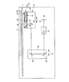
【解決手段】LEDユニット44と、LEDユニット44を挟持するように設けられた遮蔽部材42およびカバー部材43と、遮蔽部材42の対向面42aおよびカバー部材43の対向面43bに設けられ、LEDパッケージ46からの光を原稿Pの照射領域W1に対して副走査方向の前後方向から照射する反射部47〜49とを備えた原稿照明部56において、LEDユニット44を遮蔽部材42およびカバー部材43に着脱自在に設け、遮蔽部材42の対向面42aおよびカバー部材43の対向面43bに、LEDユニット44と反射部47〜49との位置決めを行う溝50、51を設ける。
【選択図】図3
Description
この構成により、発光素子を反射部に対して主走査方向と平行になるように第1の挟持部材および第2の挟持部材に位置決めすることができるため、光源および反射部を照射領域に対して最適な位置に設置することができ、照射領域における副走査方向の照度分布のばらつきを少なくして、常に安定した光量を維持することができる。
この構成により、光源を反射部に対して主走査方向に略直線状に設置することができるので、光源および反射部を照射領域に対して最適な位置に設置することができ、照射領域における副走査方向の照度分布のばらつきを少なくして、常に安定した光量を維持することができる。
この構成により、原稿からの反射光を読取手段に導く光路を確保して照明手段と読取手段を光学的に遮断することができる。
(第1の実施の形態)
図1〜図15は、本発明に係る画像読取装置および画像読取装置を備えた画像形成装置の第1の実施の形態を示す図であり、本実施の形態では、カラー複写機に適用した例を示している。
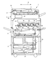
図1において、画像形成装置としてのカラー複写機1は、自動原稿搬送部(以下、ADFともいう)2と、給紙部3と、画像読取装置4と、画像形成部5とを含んで構成されている。
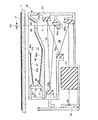
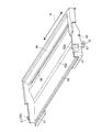
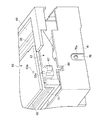
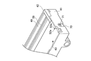
図3に示すように、一体型走査光学ユニット40は、筐体41と、筐体41に着脱自在に設けられた第2の挟持部材としての遮蔽部材42と、遮蔽部材42に着脱自在に設けられ、遮蔽部材42との間に原稿Pの照射領域W1にLEDユニット44から照射を行うための開口43aを有する第1の挟持部材としてのカバー部材43とを備えている。なお、筐体41、遮蔽部材42およびカバー部材43は、それぞれ樹脂製である。
すなわち、遮蔽部材42は、筐体41内に画像読取部54が収納された空間としての第2の空間58が画成されるように原稿照明部56と画像読取部54とを隔離している。
なお、図10は、筐体41を上方から見たときの斜視図、図11は、筐体41、遮蔽部材42およびカバー部材43を分解したときの一体型走査光学ユニット40の要部斜視図、図12は、筐体41および遮蔽部材42とカバー部材43とを分解したときの一体型走査光学ユニット40の要部斜視図、図13は、筐体41、遮蔽部材42およびカバー部材43が組み付けられた状態を示す一体型走査光学ユニット40の要部斜視図である。
本実施の形態では、カバー部材43の溝50および遮蔽部材42の溝51にLED基板45の上下端部を嵌合した後、遮蔽部材42の突起52a、52bにカバー部材43の穴53a、53bを嵌合することにより、遮蔽部材42とカバー部材43の位置決め、すなわち、反射部47〜49の位置決めと反射部47〜49に対するLED基板45の位置決めを同時に行うことができる。
このような組み付け手順によって一体型走査光学ユニット40の組み付けが行われる。
また、本実施の形態では、遮蔽部材42によって筐体41内に第1の空間57と第2の空間58とを画成しているが、これに限らず、遮蔽部材42を筐体41の上端開口部に設けてもよい。すなわち、遮蔽部材42を、筐体41内に画像読取部54を収納するための空間を画成するための蓋として用いてもよい。
図16は、本発明に係る画像読取装置および画像読取装置を備えた画像形成装置の第2の実施の形態を示す図であり、本実施の形態では、原稿照明装置を除いた画像読取装置の構成が第1の実施の形態と異なるのみであり、第1の実施の形態と同一の構成には同一番号を付して説明を省略する。
すなわち、遮蔽部材42は、筐体82内に反射ミラー83が収納された空間としての第2の空間が画成されるように原稿照明部56と反射ミラー83とを隔離している。
また、本実施の形態では、遮蔽部材42によって筐体82内に第1の空間と第2の空間とを画成しているが、これに限らず、遮蔽部材42を筐体82の上端開口部に設けてもよい。すなわち、遮蔽部材42を、筐体82内に反射ミラー83を収納するための空間を画成するための蓋として用いてもよい。
4 画像読取装置
5 画像形成部(画像形成手段)
40 一体型走査光学ユニット(走査光学ユニット)
41、82 筐体
42 遮蔽部材(第2の挟持部材)
42a 対向面(第2の対向面)
43 カバー部材(第1の挟持部材)
43a 開口
43b 対向面(第1の対向面)
44 LEDユニット(光源)
46 LEDパッケージ(発光素子)
47、48、49 反射部
50 溝(位置決め手段)
51 溝(位置決め手段)
54 画像読取部(読取手段)
56 原稿照明部(原稿照明装置)
58 第2の空間(空間)
59 スリット
60a〜60e、83〜85 反射ミラー
61、87 結像レンズ
63、88 CCD(撮像素子)
81 第1の走行体(走査光学ユニット)
P 原稿
W1 読取領域
Claims (9)
- 光源と、前記光源を挟持するように設けられた第1の挟持部材および第2の挟持部材と、前記第1の挟持部材の第1の対向面および前記第1の対向面に対向する前記第2の挟持部材の第2の対向面に設けられ、前記光源からの光を原稿の照射領域に対して副走査方向の前後方向から照射する反射部とを含んで構成される原稿照明装置において、
前記光源が前記第1の挟持部材および前記第2の挟持部材に着脱自在に設けられ、前記第1の挟持部材の第1の対向面および前記第2の挟持部材の第2の対向面に、前記光源と前記反射部との位置決めを行う位置決め手段が設けられることを特徴とする原稿照明装置。 - 前記光源が、主走査方向に略直線状に配列された複数の発光素子を有することを特徴とする請求項1に記載の原稿照明装置。
- 前記第1の挟持部材が前記第2の挟持部材に着脱自在に設けられるとともに、前記第1の挟持部材および前記第2の挟持部材との間に前記光源から原稿に照射を行うための開口が設けられ、
前記第1の挟持部材が、前記光源を外部から遮蔽するカバー部材を構成することを特徴とする請求項1または請求項2に記載の原稿照明装置。 - 前記位置決め手段が、原稿の主走査方向に沿って延在し、前記光源が嵌合される溝から構成されることを特徴とする請求項1ないし請求項3のいずれか1項に記載の原稿照明装置。
- 請求項1ないし請求項4のいずれか1項に記載の原稿照明装置を備えた走査光学ユニットであって、
前記原稿照明装置が着脱自在に取付けられるとともに、原稿から反射された光を読み取る読取手段を内蔵し、原稿の副走査方向に移動自在な筐体を備え、
前記第2の挟持部材が、前記筐体内に前記読取手段が収納された空間が画成されるように前記原稿照明装置と前記読取手段とを隔離し、前記第2の挟持部材に、前記原稿から反射された光を前記空間に導くように主走査方向に延在する長尺のスリットが設けられることを特徴とする一体型走査光学ユニット。 - 前記読取手段が、前記スリットを通して前記空間に導かれた原稿からの光を反射させる複数の反射ミラーと、前記反射ミラーで反射された光を結像させる結像レンズと、前記結像レンズの結像位置に配置され、原稿の画像を読み取る撮像素子とを備えたことを特徴とする請求項5に記載の走査光学ユニット。
- 請求項1ないし請求項4のいずれか1項に記載の原稿照明装置を備えた走査光学ユニットであって、
少なくとも原稿から反射された光を読み取る読取手段に向かって反射する反射ミラーを内蔵し、原稿の副走査方向に移動自在な筐体を備え、
前記第2の挟持部材が、前記筐体内に前記反射ミラーが収納された空間が画成されるように前記原稿照明装置と前記反射ミラーとを隔離し、前記第2の挟持部材に、前記原稿から反射された光を前記空間に導くように主走査方向に延在する長尺のスリットが設けられることを特徴とする一体型走査光学ユニット。 - 請求項5ないし請求項7のいずれか1項に記載の走査光学ユニットを備えた画像読取装置であって、
前記原稿照明装置を副走査方向に移動させる駆動手段を備えたことを特徴とする画像読取装置。 - 請求項8に記載の画像読取装置を備えた画像形成装置であって、前記読取手段によって読み取った画像を記録媒体上に形成する画像形成手段を有することを特徴とする画像形成装置。
Priority Applications (2)
| Application Number | Priority Date | Filing Date | Title |
|---|---|---|---|
| JP2008162025A JP5015867B2 (ja) | 2008-06-20 | 2008-06-20 | 原稿照明装置、画像読取装置および画像形成装置 |
| US12/457,276 US8339682B2 (en) | 2008-06-20 | 2009-06-05 | Lighting device for use in an optical scanning unit, of an image reader |
Applications Claiming Priority (1)
| Application Number | Priority Date | Filing Date | Title |
|---|---|---|---|
| JP2008162025A JP5015867B2 (ja) | 2008-06-20 | 2008-06-20 | 原稿照明装置、画像読取装置および画像形成装置 |
Publications (2)
| Publication Number | Publication Date |
|---|---|
| JP2010004365A true JP2010004365A (ja) | 2010-01-07 |
| JP5015867B2 JP5015867B2 (ja) | 2012-08-29 |
Family
ID=41430957
Family Applications (1)
| Application Number | Title | Priority Date | Filing Date |
|---|---|---|---|
| JP2008162025A Expired - Fee Related JP5015867B2 (ja) | 2008-06-20 | 2008-06-20 | 原稿照明装置、画像読取装置および画像形成装置 |
Country Status (2)
| Country | Link |
|---|---|
| US (1) | US8339682B2 (ja) |
| JP (1) | JP5015867B2 (ja) |
Cited By (1)
| Publication number | Priority date | Publication date | Assignee | Title |
|---|---|---|---|---|
| US9264572B2 (en) | 2011-10-25 | 2016-02-16 | Mitsubishi Electric Corporation | Image reading device |
Families Citing this family (6)
| Publication number | Priority date | Publication date | Assignee | Title |
|---|---|---|---|---|
| JP2010130056A (ja) | 2008-11-25 | 2010-06-10 | Ricoh Co Ltd | 光照射装置、画像読取装置および画像形成装置 |
| JP5359370B2 (ja) | 2009-02-26 | 2013-12-04 | 株式会社リコー | 原稿照明装置並びにそれを用いた画像読取装置 |
| JP5358550B2 (ja) * | 2010-11-30 | 2013-12-04 | 京セラドキュメントソリューションズ株式会社 | 画像読取装置及び画像形成装置 |
| CN102611820B (zh) * | 2011-01-21 | 2016-08-03 | 精工爱普生株式会社 | 图像读取装置 |
| JP6435790B2 (ja) * | 2014-11-11 | 2018-12-12 | 株式会社リコー | 光照射装置、画像読取装置及び画像形成装置 |
| JP6634896B2 (ja) | 2016-03-09 | 2020-01-22 | 株式会社リコー | 光照射装置、画像読取装置および画像形成装置 |
Citations (5)
| Publication number | Priority date | Publication date | Assignee | Title |
|---|---|---|---|---|
| JPS63137340U (ja) * | 1987-02-28 | 1988-09-09 | ||
| JPH07335016A (ja) * | 1994-06-10 | 1995-12-22 | Ricoh Co Ltd | 照明装置発光ランプまわりの冷却構造 |
| JPH09307714A (ja) * | 1996-05-10 | 1997-11-28 | Brother Ind Ltd | 画像読取装置 |
| JP2001083622A (ja) * | 1999-09-13 | 2001-03-30 | Ricoh Co Ltd | 原稿露光走査装置 |
| JP2003158614A (ja) * | 2001-11-20 | 2003-05-30 | Canon Inc | 画像読取装置 |
Family Cites Families (23)
| Publication number | Priority date | Publication date | Assignee | Title |
|---|---|---|---|---|
| US2891720A (en) * | 1956-01-11 | 1959-06-23 | Hughes Aircraft Co | Digital graph reader |
| JPS61273519A (ja) * | 1985-05-29 | 1986-12-03 | Ricoh Co Ltd | 原稿読取装置 |
| JPS63137340A (ja) | 1986-11-29 | 1988-06-09 | Toshiba Corp | 表示装置 |
| US5142137A (en) * | 1990-05-18 | 1992-08-25 | Sharp Kabushiki Kaisha | Image sensor having clamp connecting sensing and driving components |
| JP3202856B2 (ja) * | 1993-12-28 | 2001-08-27 | 株式会社リコー | 画像読み取り装置 |
| EP0713322B1 (en) * | 1994-11-17 | 2002-03-06 | Nikon Corporation | Image input device |
| US5913091A (en) * | 1996-05-21 | 1999-06-15 | Minolta Co., Ltd. | Image reading apparatus |
| JP3141375B2 (ja) * | 1998-11-17 | 2001-03-05 | セイコーエプソン株式会社 | 画像読み取り装置および画像読み取り方法 |
| JP2001230902A (ja) | 2000-02-16 | 2001-08-24 | Matsushita Electric Ind Co Ltd | 画像読取り装置 |
| JP4625279B2 (ja) | 2004-07-09 | 2011-02-02 | 株式会社リコー | 照明装置、画像読取装置及び画像形成装置 |
| US8098411B2 (en) * | 2004-08-31 | 2012-01-17 | Brother Kogyo Kabushiki Kaisha | Image reading apparatus |
| EP1734388A1 (en) * | 2005-06-14 | 2006-12-20 | Ricoh Company, Ltd. | Optical irradiation apparatus, image reading apparatus using the same, and image forming apparatus using the same |
| JP2007078104A (ja) | 2005-09-15 | 2007-03-29 | Seiko Epson Corp | クランプおよびこれを用いたミラー保持機構ならびに画像読み取り装置 |
| JP4687350B2 (ja) * | 2005-09-15 | 2011-05-25 | ブラザー工業株式会社 | 原稿搬送装置、画像読取装置 |
| JP4569434B2 (ja) * | 2005-09-28 | 2010-10-27 | ブラザー工業株式会社 | 画像読取装置 |
| JP4548295B2 (ja) * | 2005-09-29 | 2010-09-22 | ブラザー工業株式会社 | 画像読取装置 |
| JP2007221360A (ja) | 2006-02-15 | 2007-08-30 | Rohm Co Ltd | 画像読取装置およびその製造方法 |
| JP2007221359A (ja) | 2006-02-15 | 2007-08-30 | Rohm Co Ltd | 画像読取装置およびその製造方法 |
| JP4165576B2 (ja) * | 2006-04-27 | 2008-10-15 | ブラザー工業株式会社 | 画像読取装置 |
| JP4273160B2 (ja) * | 2006-07-31 | 2009-06-03 | シャープ株式会社 | 原稿読取装置およびその位置調整量の算出方法 |
| US8614413B2 (en) * | 2007-01-31 | 2013-12-24 | Ricoh Company, Ltd. | Image reading apparatus to illuminate light on an original document with an optical member having four planes positioned such that the light incident side is smaller in size than the light exit side |
| JP4979452B2 (ja) * | 2007-05-07 | 2012-07-18 | キヤノン株式会社 | 画像読取装置 |
| JP5735738B2 (ja) * | 2009-10-06 | 2015-06-17 | キヤノン株式会社 | 画像読取装置 |
-
2008
- 2008-06-20 JP JP2008162025A patent/JP5015867B2/ja not_active Expired - Fee Related
-
2009
- 2009-06-05 US US12/457,276 patent/US8339682B2/en active Active
Patent Citations (5)
| Publication number | Priority date | Publication date | Assignee | Title |
|---|---|---|---|---|
| JPS63137340U (ja) * | 1987-02-28 | 1988-09-09 | ||
| JPH07335016A (ja) * | 1994-06-10 | 1995-12-22 | Ricoh Co Ltd | 照明装置発光ランプまわりの冷却構造 |
| JPH09307714A (ja) * | 1996-05-10 | 1997-11-28 | Brother Ind Ltd | 画像読取装置 |
| JP2001083622A (ja) * | 1999-09-13 | 2001-03-30 | Ricoh Co Ltd | 原稿露光走査装置 |
| JP2003158614A (ja) * | 2001-11-20 | 2003-05-30 | Canon Inc | 画像読取装置 |
Cited By (1)
| Publication number | Priority date | Publication date | Assignee | Title |
|---|---|---|---|---|
| US9264572B2 (en) | 2011-10-25 | 2016-02-16 | Mitsubishi Electric Corporation | Image reading device |
Also Published As
| Publication number | Publication date |
|---|---|
| US20090316224A1 (en) | 2009-12-24 |
| US8339682B2 (en) | 2012-12-25 |
| JP5015867B2 (ja) | 2012-08-29 |
Similar Documents
| Publication | Publication Date | Title |
|---|---|---|
| JP5015867B2 (ja) | 原稿照明装置、画像読取装置および画像形成装置 | |
| JP5353084B2 (ja) | 画像読取装置および画像読取装置を備えた画像形成装置 | |
| US8767274B2 (en) | Image sensor unit, image reader, and image forming apparatus | |
| JP4754409B2 (ja) | 画像読取装置および画像形成装置 | |
| JP6528989B2 (ja) | 照明装置、画像読取装置および画像形成装置 | |
| JP5699808B2 (ja) | 導光部材、原稿照明装置、画像読取装置および画像形成装置 | |
| JP5644053B2 (ja) | 原稿照明装置、走査光学ユニット、画像読取装置および画像形成装置 | |
| JP6435790B2 (ja) | 光照射装置、画像読取装置及び画像形成装置 | |
| JP2013115763A (ja) | 光照射装置、画像読取装置および画像形成装置 | |
| JP2008129247A (ja) | 光照射装置、画像読取装置および画像形成装置 | |
| JP6384104B2 (ja) | 一体型走査光学ユニット、画像読取装置、画像形成装置および画像送受信装置 | |
| JP5100584B2 (ja) | 照明系及びそれを用いた画像読取装置 | |
| JP5811595B2 (ja) | 原稿照明装置、画像読取装置および画像形成装置 | |
| JP5724374B2 (ja) | 原稿照明装置、画像読取装置および画像形成装置 | |
| JP2011087122A (ja) | 原稿照明装置、走査光学ユニット、画像読取装置および画像形成装置 | |
| JP5195549B2 (ja) | 画像読取装置および画像読取装置を備えた画像形成装置 | |
| JP5910924B2 (ja) | 照明装置、画像読取装置、および画像形成装置 | |
| JP2012220566A (ja) | 原稿照明装置、走査光学ユニット、画像読取装置および画像形成装置 | |
| JP6212916B2 (ja) | 原稿照明装置、走査光学ユニット、画像読取装置および画像形成装置 | |
| JP2010204539A (ja) | 原稿照明装置、画像読取装置および画像形成装置 | |
| JP2015167409A (ja) | 画像読取装置および画像形成装置 | |
| JP5768904B2 (ja) | 画像読取装置および画像形成装置 | |
| JP2010191180A (ja) | 原稿照明装置、画像読取装置および画像形成装置 | |
| JP2013084465A (ja) | 原稿照明ユニット、原稿読取装置、および画像形成装置 | |
| JP2014179834A (ja) | 原稿照明装置及び走査光学ユニット及び画像読取装置及び画像形成装置 |
Legal Events
| Date | Code | Title | Description |
|---|---|---|---|
| A621 | Written request for application examination |
Free format text: JAPANESE INTERMEDIATE CODE: A621 Effective date: 20110112 |
|
| A977 | Report on retrieval |
Free format text: JAPANESE INTERMEDIATE CODE: A971007 Effective date: 20111215 |
|
| A131 | Notification of reasons for refusal |
Free format text: JAPANESE INTERMEDIATE CODE: A131 Effective date: 20111227 |
|
| A521 | Request for written amendment filed |
Free format text: JAPANESE INTERMEDIATE CODE: A523 Effective date: 20120216 |
|
| A131 | Notification of reasons for refusal |
Free format text: JAPANESE INTERMEDIATE CODE: A131 Effective date: 20120508 |
|
| A521 | Request for written amendment filed |
Free format text: JAPANESE INTERMEDIATE CODE: A523 Effective date: 20120516 |
|
| TRDD | Decision of grant or rejection written | ||
| A01 | Written decision to grant a patent or to grant a registration (utility model) |
Free format text: JAPANESE INTERMEDIATE CODE: A01 Effective date: 20120605 |
|
| A01 | Written decision to grant a patent or to grant a registration (utility model) |
Free format text: JAPANESE INTERMEDIATE CODE: A01 |
|
| A61 | First payment of annual fees (during grant procedure) |
Free format text: JAPANESE INTERMEDIATE CODE: A61 Effective date: 20120607 |
|
| FPAY | Renewal fee payment (event date is renewal date of database) |
Free format text: PAYMENT UNTIL: 20150615 Year of fee payment: 3 |
|
| R150 | Certificate of patent or registration of utility model |
Ref document number: 5015867 Country of ref document: JP Free format text: JAPANESE INTERMEDIATE CODE: R150 Free format text: JAPANESE INTERMEDIATE CODE: R150 |
|
| LAPS | Cancellation because of no payment of annual fees |