JP2009527770A - Method and system for performing angle-resolved Fourier domain optical coherence tomography - Google Patents
Method and system for performing angle-resolved Fourier domain optical coherence tomography Download PDFInfo
- Publication number
- JP2009527770A JP2009527770A JP2008556520A JP2008556520A JP2009527770A JP 2009527770 A JP2009527770 A JP 2009527770A JP 2008556520 A JP2008556520 A JP 2008556520A JP 2008556520 A JP2008556520 A JP 2008556520A JP 2009527770 A JP2009527770 A JP 2009527770A
- Authority
- JP
- Japan
- Prior art keywords
- sample
- electromagnetic wave
- component
- electromagnetic waves
- signal
- Prior art date
- Legal status (The legal status is an assumption and is not a legal conclusion. Google has not performed a legal analysis and makes no representation as to the accuracy of the status listed.)
- Pending
Links
- 0 C*(C)C1CSCC1 Chemical compound C*(C)C1CSCC1 0.000 description 1
Images
Classifications
-
- G—PHYSICS
- G01—MEASURING; TESTING
- G01N—INVESTIGATING OR ANALYSING MATERIALS BY DETERMINING THEIR CHEMICAL OR PHYSICAL PROPERTIES
- G01N21/00—Investigating or analysing materials by the use of optical means, i.e. using sub-millimetre waves, infrared, visible or ultraviolet light
- G01N21/17—Systems in which incident light is modified in accordance with the properties of the material investigated
- G01N21/47—Scattering, i.e. diffuse reflection
- G01N21/4795—Scattering, i.e. diffuse reflection spatially resolved investigating of object in scattering medium
-
- A—HUMAN NECESSITIES
- A61—MEDICAL OR VETERINARY SCIENCE; HYGIENE
- A61B—DIAGNOSIS; SURGERY; IDENTIFICATION
- A61B5/00—Measuring for diagnostic purposes; Identification of persons
- A61B5/0059—Measuring for diagnostic purposes; Identification of persons using light, e.g. diagnosis by transillumination, diascopy, fluorescence
- A61B5/0062—Arrangements for scanning
- A61B5/0066—Optical coherence imaging
-
- G—PHYSICS
- G01—MEASURING; TESTING
- G01B—MEASURING LENGTH, THICKNESS OR SIMILAR LINEAR DIMENSIONS; MEASURING ANGLES; MEASURING AREAS; MEASURING IRREGULARITIES OF SURFACES OR CONTOURS
- G01B9/00—Measuring instruments characterised by the use of optical techniques
- G01B9/02—Interferometers
- G01B9/02041—Interferometers characterised by particular imaging or detection techniques
- G01B9/02043—Imaging of the Fourier or pupil or back focal plane, i.e. angle resolved imaging
-
- G—PHYSICS
- G01—MEASURING; TESTING
- G01B—MEASURING LENGTH, THICKNESS OR SIMILAR LINEAR DIMENSIONS; MEASURING ANGLES; MEASURING AREAS; MEASURING IRREGULARITIES OF SURFACES OR CONTOURS
- G01B9/00—Measuring instruments characterised by the use of optical techniques
- G01B9/02—Interferometers
- G01B9/02083—Interferometers characterised by particular signal processing and presentation
- G01B9/02087—Combining two or more images of the same region
-
- G—PHYSICS
- G01—MEASURING; TESTING
- G01B—MEASURING LENGTH, THICKNESS OR SIMILAR LINEAR DIMENSIONS; MEASURING ANGLES; MEASURING AREAS; MEASURING IRREGULARITIES OF SURFACES OR CONTOURS
- G01B9/00—Measuring instruments characterised by the use of optical techniques
- G01B9/02—Interferometers
- G01B9/0209—Low-coherence interferometers
- G01B9/02091—Tomographic interferometers, e.g. based on optical coherence
-
- A—HUMAN NECESSITIES
- A61—MEDICAL OR VETERINARY SCIENCE; HYGIENE
- A61B—DIAGNOSIS; SURGERY; IDENTIFICATION
- A61B5/00—Measuring for diagnostic purposes; Identification of persons
- A61B5/0059—Measuring for diagnostic purposes; Identification of persons using light, e.g. diagnosis by transillumination, diascopy, fluorescence
- A61B5/0073—Measuring for diagnostic purposes; Identification of persons using light, e.g. diagnosis by transillumination, diascopy, fluorescence by tomography, i.e. reconstruction of 3D images from 2D projections
-
- G—PHYSICS
- G01—MEASURING; TESTING
- G01B—MEASURING LENGTH, THICKNESS OR SIMILAR LINEAR DIMENSIONS; MEASURING ANGLES; MEASURING AREAS; MEASURING IRREGULARITIES OF SURFACES OR CONTOURS
- G01B2290/00—Aspects of interferometers not specifically covered by any group under G01B9/02
- G01B2290/70—Using polarization in the interferometer
-
- G—PHYSICS
- G01—MEASURING; TESTING
- G01N—INVESTIGATING OR ANALYSING MATERIALS BY DETERMINING THEIR CHEMICAL OR PHYSICAL PROPERTIES
- G01N21/00—Investigating or analysing materials by the use of optical means, i.e. using sub-millimetre waves, infrared, visible or ultraviolet light
- G01N21/17—Systems in which incident light is modified in accordance with the properties of the material investigated
- G01N21/47—Scattering, i.e. diffuse reflection
- G01N2021/4704—Angular selective
- G01N2021/4711—Multiangle measurement
- G01N2021/4714—Continuous plural angles
Landscapes
- Physics & Mathematics (AREA)
- Health & Medical Sciences (AREA)
- General Physics & Mathematics (AREA)
- Life Sciences & Earth Sciences (AREA)
- General Health & Medical Sciences (AREA)
- Engineering & Computer Science (AREA)
- Nuclear Medicine, Radiotherapy & Molecular Imaging (AREA)
- Radiology & Medical Imaging (AREA)
- Pathology (AREA)
- Signal Processing (AREA)
- Optics & Photonics (AREA)
- Immunology (AREA)
- Biochemistry (AREA)
- Analytical Chemistry (AREA)
- Chemical & Material Sciences (AREA)
- Molecular Biology (AREA)
- Public Health (AREA)
- Veterinary Medicine (AREA)
- Biophysics (AREA)
- Animal Behavior & Ethology (AREA)
- Surgery (AREA)
- Biomedical Technology (AREA)
- Medical Informatics (AREA)
- Heart & Thoracic Surgery (AREA)
- Investigating Or Analysing Materials By Optical Means (AREA)
Abstract
本発明の代表的な実施例によれば、構成、装置、及び方法が提供される。具体的には、少なくとも1つの第1電磁波を受信することが可能であり、立体角内の少なくとも1つの第2電磁波をサンプルに対して転送することが可能である。第2電磁波は、第1電磁波と関連付けすることが可能である。複数の第3電磁波を第2電磁波と関連付けられたサンプルから受信することが可能であり、第3電磁波の少なくとも1つの部分は、立体角の外縁の外において提供されている。第3電磁波の各々と関連付けられた信号を同時に検出することが可能であり、これらの信号は、サンプル内の複数の深さにおけるサンプルの情報と関連付けられている。第3電磁波の中の少なくとも1つのものを使用することにより、第3電磁波の別のものを利用する必要性を伴うことなしに、サンプル内の複数の深さを判定することが可能である。 In accordance with exemplary embodiments of the present invention, configurations, apparatus, and methods are provided. Specifically, at least one first electromagnetic wave can be received, and at least one second electromagnetic wave within a solid angle can be transferred to the sample. The second electromagnetic wave can be associated with the first electromagnetic wave. A plurality of third electromagnetic waves can be received from a sample associated with the second electromagnetic wave, and at least one portion of the third electromagnetic wave is provided outside the outer edge of the solid angle. Signals associated with each of the third electromagnetic waves can be detected simultaneously, and these signals are associated with sample information at multiple depths within the sample. By using at least one of the third electromagnetic waves, it is possible to determine multiple depths in the sample without the need to utilize another one of the third electromagnetic waves.
Description
本発明は、角度分解型のフーリエドメイン光干渉断層撮影法を遂行する方法及びシステムに関するものであり、更に詳しくいえば、フーリエドメイン光干渉断層撮影法の手法を使用して遂行される透明サンプル及び混濁サンプルからの空間分解型の角度別後方散乱分布の計測に関するものである。 The present invention relates to a method and system for performing angle-resolved Fourier domain optical coherence tomography, and more particularly, to a transparent sample performed using a Fourier domain optical coherence tomography technique, and This relates to the measurement of spatially resolved backscattering distribution by angle from a turbid sample.
(関連出願に対する相互参照)
本出願は、2006年2月24日付けで出願された米国特許出願第60/776,544号に基づくものである。さらに、本出願は、この米国特許出願の優先権の利益を主張するものであり、この米国特許出願の開示内容は、本願明細書で言及することによって、その全ての内容が本願明細書に包含されている。
(連邦政府による資金提供を受けた研究開発の記載)
本発明は、国立衛生研究所(National Institutes of Health)によって付与された契約第R01 CA103769号の下に、米国政府の支援によって実現したものである。従って、米国政府は、本発明における特定の権利を有している。
(Cross-reference to related applications)
This application is based on US patent application Ser. No. 60 / 776,544, filed Feb. 24, 2006. In addition, this application claims the benefit of priority of this US patent application, and the disclosure of this US patent application is hereby incorporated by reference in its entirety. Has been.
(Description of research and development funded by the federal government)
The present invention has been realized with the support of the US government under Contract No. R01 CA103769 awarded by the National Institutes of Health. Accordingly, the US government has certain rights in the invention.
光干渉断層撮影法(Optical Coherence Tomography:OCT)によれば、数ミクロン(μm)〜数十ミクロンのレベルの分解能における生物学的サンプルの断面画像を取得することが可能であり、従って、組織の微細構造を詳細に撮像することが可能である。フーリエドメインOCT(Fourier-Domain OCT:FD−OCT)は、高速撮像を実現させるような、時間ドメインOCTよりも大幅に改善された感度を提供することが可能であることが実証されている。より具体的には、FD−OCTは、例えば、2004年9月8日付けで出願された国際特許出願第PCT/US2004/029148号、2005年11月2日付けで出願された米国特許出願第11/266,779号、及び2004年7月9日付けで出願された米国特許出願第10/501,276号の中の少なくとも1つのものに記述されているように、スペクトルドメインOCT(Spectral-Domain OCT:SD−OCT)及び光学周波数ドメイン撮像(Optical Frequency Domain Imaging:OFDI)という2つの構成において実施されている。FD−OCTは、心血管、胃腸、及び網膜の撮像を含む多数の臨床環境における形態学的な変化を識別するツールとして大きな可能性を有していることが明らかになっている。 Optical coherence tomography (OCT) makes it possible to obtain cross-sectional images of biological samples at resolutions on the order of several microns (μm) to several tens of microns, thus It is possible to image the fine structure in detail. Fourier-Domain OCT (FD-OCT) has been demonstrated to be able to provide significantly improved sensitivity over time-domain OCT, such as to achieve high-speed imaging. More specifically, FD-OCT is disclosed in, for example, International Patent Application No. PCT / US2004 / 029148 filed on Sep. 8, 2004, and U.S. Patent Application No. filed on Nov. 2, 2005. No. 11 / 266,779, and US patent application Ser. No. 10 / 501,276 filed Jul. 9, 2004, as described in Spectral Domain OCT (Spectral- Domain OCT (SD-OCT) and optical frequency domain imaging (OFDI). FD-OCT has proven to have great potential as a tool to identify morphological changes in a number of clinical settings, including cardiovascular, gastrointestinal, and retinal imaging.
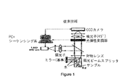
従来のOCTシステム及び方法における1つの制限は、180度に中心を有する1つの角度レンジからの後方散乱光しか収集されないという点にある。このような制限は、光学コヒーレンス顕微鏡法(Optical Coherence Microscopy:OCM)システムにも当てはまる。この場合には、アレイ検出を使用することにより、ビームを走査することなく正面の二次元画像を生成することが可能である。イー.ビューリペア(E. Beaurepaire)らによる「全視野光学コヒーレンス顕微鏡法(Full-Field Optical Coherence Microscopy」(光学レター(Optics Letters),23(4):244〜246頁,1998年)に記述されている上記のようなOCMシステムの一例が図1に示されている。スペックル(Speckle)を低減させることが可能である角度合成(Angular Compounding)の手法を使用することにより、異なる角度から後方散乱した光の取得を実施することが可能である。スペックルは、一般的に、画像の散乱領域内においてチェッカーパターンとして現れるものであり、この結果として、組織の反射率におけるわずかな違いを識別することが更に困難になる。 One limitation in conventional OCT systems and methods is that only backscattered light from one angular range centered at 180 degrees is collected. Such limitations also apply to optical coherence microscopy (OCM) systems. In this case, by using array detection, it is possible to generate a frontal two-dimensional image without scanning the beam. E. E. Beaurepaire et al., Described in “Full-Field Optical Coherence Microscopy” (Optics Letters, 23 (4): 244-246, 1998). An example of such an OCM system is shown in Figure 1. By using an Angular Compounding technique that can reduce Speckle, it was backscattered from different angles. Light acquisition can be performed, and speckle generally appears as a checkered pattern in the scattering region of the image, and as a result, identifies slight differences in tissue reflectivity. Becomes even more difficult.
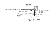
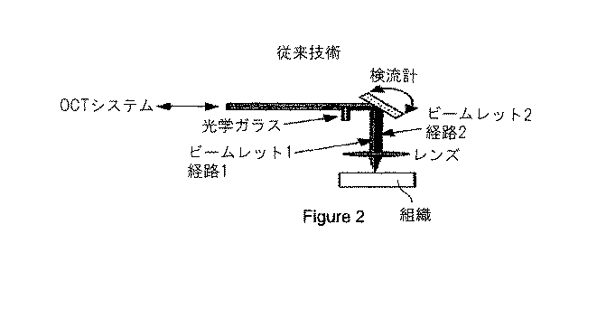
角度合成を実現させるOCT環境において異なる入射角度にて後方散乱光を取得する方法及びシステムは、経路長エンコーディングを利用している。エヌ.イフティミア(N. Iftimia)らによる「経路長エンコーディングを使用した角度合成による光学コヒーレンス顕微鏡法におけるスペックル低減(Speckle Reduction in Optical Coherence Tomography by 'Path Length Encoded' Angular Compounding」(生物医学光学ジャーナル(Journal of Biomedical Optics),8(2):260〜263頁,2003年)に記述されているこのようなシステムの例が図2に示されている。例えば、光学ガラスを撮像ビームの経路内に配置することにより、入射フィールドを複数のビームレットに分割することが可能である。この光学ガラスにより、入射ビームの一部(ビームレット2)が、ビームレット1よりも大きな経路長の遅延を生ずることになる。更には、ビームレット2は、ビームレット1とは異なる角度においてサンプルを照射している。この結果として、サンプルの(それぞれが異なる角度において取得された)複数のOCT画像がOCTディスプレイ上に同時に出現することになる。上記の方法及びシステムは、高速撮像には適しているが、一般に、多数の角度に対する適切なスケーリングが行われず、且つ、空間分解能と取得角度数との間のトレードオフが必要となる可能性がある。
A method and system for acquiring backscattered light at different angles of incidence in an OCT environment that implements angle synthesis utilizes path length encoding. N. N. Iftimia et al. “Speckle Reduction in Optical Coherence Tomography by 'Path Length Encoded' Angular Compounding” (Journal of Optical Medicine An example of such a system described in Biomedical Optics), 8 (2): 260-263, 2003) is shown in Figure 2. For example, optical glass is placed in the path of the imaging beam. It is possible to divide the incident field into a plurality of beamlets, because this optical glass causes part of the incident beam (beamlet 2) to have a longer path length delay than
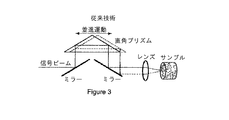
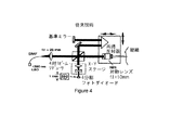
別の方法及びシステムは、直角プリズムを並進運動させることにより、サンプルアームからの光を合焦レンズ(Focusing Lens)上の異なる位置に導いている。エム.バシカンスキ(M. Bashkansky)らによる「光学コヒーレンス顕微鏡法におけるスペックルの統計学及びスペックル低減(Statistics and Reduction of Speckle in Optical Coherence Tomography)」(光学レター(Optics Letters),25(8):545〜547頁,2000年)に記述されている上記のようなシステムの例が図3に示されている。上記の方法及びシステムにおいては、一般に、180度に中心を有する狭い角度レンジにおける後方散乱光を収集しているが、サンプルの法線に対する入射ビームの入射角度がプリズムの位置と共に変化している。このような方法及びシステムは、角度別後方散乱分布の計測を提供しない(又は、場合によっては、許容しない)可能性が高い。画像の取得可能速度が、振動方式においてプリズムの並進運動が可能である速度によって制限されることになるであろう。更に別の方法及びシステムにおいては、4つの検出器によるOCT信号の検出を同時に遂行することが可能であり、これにより、スペックル低減のための角度合成が実現されている。ジェイ.エム.シュミット(J. M. Schmitt)による「光学コヒーレンス顕微鏡法におけるスペックル低減のためのアレイ検出(Array Detection for Speckle Reduction in Optical Coherence Microscopy)」(医学及び生物学の中の物理(Physics in Medicine and Biology),42(7):1427〜1439頁,1997年)に記述されている上記のようなシステムの一例が図4に示されている。具体的には、このシステム内の基準ビームは、一般に、入射ビームよりも大きくない。従って、上記のシステムは、角度別後方散乱分布の計測には、有用ではないであろう。更には、各々の検出器要素は、異なる角度において後方散乱光を受光しているが、所定の検出器要素にて収集される光によって範囲が定まる立体角が、入射ビームによって範囲が定まる立体角の中に完全に含まれている。上記のシステムにおける検出は、時間ドメインにおいて遂行されている。 Another method and system directs light from the sample arm to different positions on the focusing lens by translating a right-angle prism. M. “Statistics and Reduction of Speckle in Optical Coherence Tomography” (Optics Letters, 25 (8): 545) by M. Bashkansky et al. An example of such a system described on page 547 (2000) is shown in FIG. In the above method and system, backscattered light is collected in a narrow angular range centered at 180 degrees, but the incident angle of the incident beam with respect to the sample normal varies with the prism position. Such methods and systems are likely not to provide (or in some cases not tolerate) measurement of angular backscatter distributions. The speed at which images can be acquired will be limited by the speed at which the prism can translate in a vibrating manner. In yet another method and system, it is possible to simultaneously detect OCT signals by four detectors, thereby realizing angle synthesis for speckle reduction. Jay. M. “Array Detection for Speckle Reduction in Optical Coherence Microscopy” by JM Schmitt (Physics in Medicine and Biology), 42 (7): pages 1427 to 1439 (1997), an example of such a system is shown in FIG. Specifically, the reference beam in this system is generally not larger than the incident beam. Thus, the above system would not be useful for measuring angular backscatter distributions. Furthermore, each detector element receives backscattered light at a different angle, but the solid angle defined by the light collected by a given detector element is the solid angle defined by the incident beam. Is completely contained within. The detection in the above system is performed in the time domain.
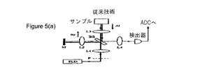
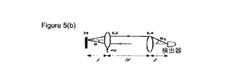
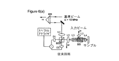
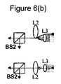
光散乱分光法の分野においては、後方散乱光の角度別分布は、一般に、組織内における散乱粒子のサイズ分布に関する情報を含んでいることが知られている。OCTの光学分解能が制限されている場合には、反射率特性のわずかな差を有する組織間において安定したコントラストを導出する機能は、(特定の状況においては)後方散乱光の角度別分布の計測を利用することが可能である。エー.ワックス(A. Wax)らによる「光散乱分光学の低コヒーレンス干渉法を使用した角度分布の計測(Measurement of Angular Distributions by Use of Low-Coherence Interferometry for Light-Scattering Spectroscopy)」(光学レター(Optics Letters),26(6):322〜324頁,2001年)に記述されている図5(a)及び図5(b)の構成、並びに、ジェイ.ダブリュー.ピティラ(J. W. Pyhtila)らによる「改善された角度分解型の低コヒーレンス干渉法システムを使用して核形態学を決定すること(Determining Nuclear Morphology Using an Improved Angle-Resolved Low Coherence Interferometry System)」(光学エクスプレス(Optics Express),15(25):3474〜3484頁,2003年)に記述されている図6(a)及び図6(b)の構成に示されているように、高い角度分解能を有する光散乱計測のために、低コヒーレンス干渉法を使用した深さ分解型の角度別後方散乱計測(Depth-Resolved Angular Backscattering Measurements)が設計されている。 In the field of light scattering spectroscopy, it is known that the angular distribution of backscattered light generally contains information about the size distribution of the scattered particles in the tissue. When the optical resolution of OCT is limited, the ability to derive a stable contrast between tissues with slight differences in reflectivity characteristics is (in certain circumstances) measuring the angular distribution of backscattered light. Can be used. A. “Measurement of Angular Distributions by Use of Low-Coherence Interferometry for Light-Scattering Spectroscopy” by A. Wax et al. (Optics Letters ), 26 (6): 322-324, 2001), and the structure of FIG. 5 (a) and FIG. W. “Determining Nuclear Morphology Using an Improved Angle-Resolved Low Coherence Interferometry System” (Optical Express) by JW Pyhtila et al. (Optics Express), 15 (25): 3474-3484, 2003), as shown in the configuration of FIGS. 6A and 6B, light having high angular resolution. Depth-Resolved Angular Backscattering Measurements using low-coherence interferometry are designed for scatter measurements.
例えば、低コヒーレンス源からの光を改良型マイケルソン(Michelson)干渉計の2つのアームに分割し、1つのビームをサンプル(又は、サンプルアーム)に入射させ、もう1つのビームをミラー(又は、基準アーム)に入射させる。前者のサンプルアーム内の様々な後方散乱角度の選択性を提供するために、基準アーム内に配置されたレンズをミラー面に対して平行に並進運動させることが可能である。干渉光の計測は、一般に、(図5(a)及び図5(b)に示されている構成を使用して)時間ドメインにおいて、又は(図6(a)及び図6(b)に示されている構成を使用して)周波数ドメインにおいて遂行される。これらの手法によれば、一般に、角度別後方散乱分布の同時計測が不可能であり、計測速度も、レンズを正確に並進運動させることが可能である速度によって制限されることになるであろう。角度、ポイントサンプリング、及び原位置計測について最適化されてはいるが、上記のような現在実施されている角度分解型のLCIは、恐らく、生体内における臨床撮像に好適ではないであろう。 For example, light from a low coherence source is split into two arms of a modified Michelson interferometer, one beam is incident on the sample (or sample arm), and the other beam is mirrored (or Incident on the reference arm. In order to provide selectivity for various backscatter angles within the former sample arm, it is possible to translate the lens located in the reference arm parallel to the mirror plane. Interferometric light measurements are generally shown in the time domain (using the configuration shown in FIGS. 5 (a) and 5 (b)) or as shown in FIGS. 6 (a) and 6 (b). Performed in the frequency domain). These techniques generally do not allow simultaneous measurement of angular backscatter distributions, and the measurement speed will also be limited by the speed at which the lens can be accurately translated. . Although optimized for angle, point sampling, and in-situ measurements, currently implemented angle-resolved LCIs as described above are probably not suitable for in vivo clinical imaging.
従って、前述の欠点を克服する必要性が存在している。実際に、光干渉断層撮影法の撮像環境において複数の角度から後方散乱した光を同時に計測することにより、高度なスペックルの低減と付加的な形態の画像コントラストを実現させることが可能である。 Therefore, there is a need to overcome the aforementioned drawbacks. In fact, by simultaneously measuring the light backscattered from a plurality of angles in the imaging environment of optical coherence tomography, it is possible to realize advanced speckle reduction and additional forms of image contrast.
従って、前述の欠点を克服する必要性が存在している。 Therefore, there is a need to overcome the aforementioned drawbacks.
前述の問題及び/又は欠点に対処するために、且つ/又は、前述の問題及び/又は欠点を克服するために、フーリエドメイン光干渉断層撮影法の原理を使用して透明サンプル及び混濁サンプルからの空間分解型の角度別後方散乱分布を計測するような本発明に係るシステム、装置、及び方法の代表的な実施例が提供されている。更には、本発明の更なる代表的な実施例によれば、スペックルの低減を遂行すると共に、画像のコントラストを生成するために、後方散乱分布を利用したシステム及び方法も提供されている。 To address the aforementioned problems and / or drawbacks and / or to overcome the aforementioned problems and / or drawbacks, the principle of Fourier domain optical coherence tomography is used to remove from transparent and turbid samples. Exemplary embodiments of systems, apparatus and methods according to the present invention for measuring spatially resolved angular backscatter distributions are provided. Furthermore, in accordance with a further exemplary embodiment of the present invention, there is also provided a system and method that utilizes a backscatter distribution to perform speckle reduction and generate image contrast.
従って、本発明の代表的な一実施例によれば、装置及び方法が提供されている。具体的には、少なくとも1つの第1電磁波を受信することが可能であり、立体角内の少なくとも1つの第2電磁波をサンプルに対して転送することが可能である。第2電磁波は、第1電磁波と関連付けすることが可能である。複数の第3電磁波を第2電磁波と関連付けられたサンプルから受信することが可能であり、第3電磁波の少なくとも1つの部分は、立体角の外縁の外において提供されている。第3電磁波の各々と関連付けられた信号を同時に検出することが可能であり、これらの信号は、サンプル内の複数の深さ(Depth)におけるサンプルの情報と関連付けられている。第3電磁波の中の少なくとも1つのものを使用することにより、第3電磁波の別のものを利用する必要性を伴うことなしに、サンプル内の複数の深さを判定することが可能である。 Thus, according to an exemplary embodiment of the present invention, an apparatus and method are provided. Specifically, at least one first electromagnetic wave can be received, and at least one second electromagnetic wave within a solid angle can be transferred to the sample. The second electromagnetic wave can be associated with the first electromagnetic wave. A plurality of third electromagnetic waves can be received from a sample associated with the second electromagnetic wave, and at least one portion of the third electromagnetic wave is provided outside the outer edge of the solid angle. Signals associated with each of the third electromagnetic waves can be detected simultaneously, and these signals are associated with sample information at multiple depths (Depth) within the sample. By using at least one of the third electromagnetic waves, it is possible to determine multiple depths in the sample without the need to utilize another one of the third electromagnetic waves.
更には、第3電磁波の中の2つのものと、第1電磁波と関連付けられた少なくとも1つの第4電磁波との間において干渉を検出することが可能であり、サンプルと関連付けられた情報を、干渉に基づいてサンプル内の深さの関数として取得することが可能である。サンプルの少なくとも1つの部分の複屈折特性、分光特性、モーション、角度別後方散乱特性、又は弾性特性の少なくとも1つのものと関連付けられたデータを信号の関数として提供することが可能である。サンプルの少なくとも1つの部分の少なくとも1つの画像を信号の関数として生成することが可能である。サンプルの少なくとも1つの部分の複屈折特性、分光特性、モーション、角度別後方散乱特性、又は弾性特性の少なくとも1つのものと関連付けられたデータを信号の関数として提供することも可能である。データは、画像と関連付けられたコントラストデータであってよい。又、サンプルの少なくとも1つの部分の散乱特性と関連付けられたデータを信号の組み合わせの関数として提供することも可能である。更には、第3電磁波の中の単一のものを使用して信号の深さを判定することが可能である。 Furthermore, it is possible to detect interference between two of the third electromagnetic waves and at least one fourth electromagnetic wave associated with the first electromagnetic wave, and the information associated with the sample Can be obtained as a function of depth in the sample. Data associated with at least one of birefringence characteristics, spectroscopic characteristics, motion, angular backscatter characteristics, or elastic characteristics of at least one portion of the sample can be provided as a function of the signal. At least one image of at least one portion of the sample can be generated as a function of the signal. It is also possible to provide data associated with at least one of birefringence characteristics, spectroscopic characteristics, motion, angular backscattering characteristics, or elastic characteristics of at least one portion of the sample as a function of the signal. The data may be contrast data associated with the image. It is also possible to provide data associated with the scattering properties of at least one portion of the sample as a function of the signal combination. Furthermore, it is possible to determine the depth of the signal using a single one of the third electromagnetic waves.
本発明の別の代表的な実施例によれば、少なくとも1つのサンプルと関連付けられたデータの生成を円滑に遂行する装置及び方法を提供することが可能である。例えば、少なくとも1つのサンプルから提供された複数の電磁波の信号と関連付けられた第1情報を受信することが可能である。電磁波の中の少なくとも第1のものを第1軸に沿って提供することが可能であり、電磁波の中の少なくとも第2のものを、第1軸とは異なる第2軸に沿って提供することが可能である。第1情報の少なくとも1つの部分内の信号の各々のデータは、サンプル内の複数の深さのデータを包含することが可能である。少なくとも1つのサンプルの画像の少なくとも1つの部分のコントラストデータと関連付けられた第2情報を、第1情報の関数として生成することが可能である。 In accordance with another exemplary embodiment of the present invention, it is possible to provide an apparatus and method that facilitates the generation of data associated with at least one sample. For example, it is possible to receive first information associated with a plurality of electromagnetic wave signals provided from at least one sample. Providing at least a first of the electromagnetic waves along a first axis and providing at least a second of the electromagnetic waves along a second axis different from the first axis; Is possible. Each data of the signal in at least one portion of the first information may include multiple depths of data in the sample. Second information associated with the contrast data of at least one portion of the image of the at least one sample can be generated as a function of the first information.
本発明の更に別の代表的な実施例においては、更なる装置及び方法を提供することが可能である。例えば、少なくとも1つの第1電磁波を受信することが可能であり、立体角内の少なくとも1つの第2電磁波をサンプルに対して転送することが可能である。第2電磁波を第1電磁波と関連付けすることが可能である。複数の第3電磁波の中の少なくとも2つのものを第2電磁波と関連付けられたサンプルから同時に受信することが可能であり、第3電磁波の中の少なくとも1つの部分を立体角の外縁の外において提供することが可能である。第3電磁波の中の少なくとも2つのものと、第1電磁波と関連付けられた少なくとも1つの第4電磁波との間の干渉を検出することが可能である。サンプルと関連付けられた情報を、干渉に基づいてサンプル内の少なくとも1つの深さの関数として取得することが可能である。 In yet another exemplary embodiment of the present invention, additional apparatus and methods can be provided. For example, it is possible to receive at least one first electromagnetic wave and to transfer at least one second electromagnetic wave within a solid angle to the sample. The second electromagnetic wave can be associated with the first electromagnetic wave. It is possible to simultaneously receive at least two of the plurality of third electromagnetic waves from the sample associated with the second electromagnetic wave, and provide at least one portion of the third electromagnetic wave outside the outer edge of the solid angle Is possible. It is possible to detect interference between at least two of the third electromagnetic waves and at least one fourth electromagnetic wave associated with the first electromagnetic wave. Information associated with the sample can be obtained as a function of at least one depth in the sample based on the interference.
上記のような本発明の目的及びその他の目的、特徴、及び利点については、添付の特許請求の請求項との関連において、本発明の実施例に関する以下の詳細な説明を参照することにより、明らかとなるであろう。 These and other objects, features and advantages of the present invention as set forth above will become apparent upon reference to the following detailed description of the embodiments of the invention in connection with the appended claims. It will be.
本発明の更なる目的、特徴、及び利点については、本発明の例示用の実施例を示す添付図面との関連において提示されている以下の詳細な説明を参照することにより、明らかとなるであろう。 Further objects, features and advantages of the present invention will become apparent upon reference to the following detailed description, which is presented in connection with the accompanying drawings which illustrate exemplary embodiments of the invention. Let's go.
これらの図面の全体を通して、同一の参照符号及び文字は、特記されていない限り、図示の実施例の類似した特徴、要素、構成要素、又は部分を表すべく使用されている。更には、以下においては、添付図面を参照し、本発明について詳細に説明しているが、この説明は、例示用の実施例との関連において提示されている。添付の特許請求の範囲の請求項に規定されている本発明の真の範囲及び精神を逸脱することなしに、説明対象の実施例に対する変更及び変形を実施することが可能であると解釈されたい。 Throughout these drawings, the same reference numerals and characters are used to represent similar features, elements, components, or parts of the illustrated embodiments unless otherwise specified. Furthermore, in the following, the present invention will be described in detail with reference to the accompanying drawings, this description being presented in the context of an exemplary embodiment. It should be construed that changes and modifications may be made to the described embodiments without departing from the true scope and spirit of the invention as defined in the appended claims. .
(角度分解型のFD−OCTの典型的な原理)
以下、フーリエドメインOCTの環境において、角度分解型のFD−OCTについて説明する。例えば、FD−OCTにおいては、混濁媒体、半混濁媒体、又は透明媒体の深さ分解型の反射率を取得するために、基準光と撮像サンプルから後方散乱された光との間の干渉を周波数ドメインにおいて計測することが可能である。入力光源の(例えば、光やレーザービーム等の)電磁波を基準ビームとサンプルビームに分割することが可能である。サンプルビーム光を撮像対象のサンプルに導くことが可能であり、サンプルからの後方散乱光を基準ビーム光と干渉させることができる。角度分解型のFD−OCTの場合には、入射サンプルビームによって範囲が定まるものを上回る後方散乱の角度範囲との干渉を実現させるべく、サンプルビームの断面エリアよりも断面エリアを大きくすることができるように、基準ビームを空間的に拡張することが可能である。基準ビームと後方散乱光との間の干渉は、例えば、検出器アレイを使用して計測することが可能である。この検出器アレイは、(i)単一集積回路要素上に集積化された検出器、及び/又は(ii)空間内に一緒に提供された個別の検出器から構成されることが可能である。入射ビームに対する検出後方散乱光の角度依存性は、空間ドメインにおいて、検出器アレイの少なくとも1つの次元に沿った光強度の分布としてエンコーディング可能である。干渉光の波長依存性を計測することが可能であり、異なる後方散乱角度のレンジに対応するフーリエ分析軸方向反射率プロファイルを取得することが可能である。
(Typical principles of angle-resolved FD-OCT)
Hereinafter, angle-resolved FD-OCT will be described in the environment of Fourier domain OCT. For example, in FD-OCT, in order to obtain a depth-resolved reflectance of a turbid medium, a semi-turbid medium, or a transparent medium, interference between the reference light and the light backscattered from the imaging sample is frequency. It can be measured in the domain. It is possible to split the electromagnetic wave (eg, light, laser beam, etc.) of the input light source into a reference beam and a sample beam. The sample beam light can be guided to the sample to be imaged, and the backscattered light from the sample can interfere with the reference beam light. In the case of angle-resolved FD-OCT, the cross-sectional area can be made larger than the cross-sectional area of the sample beam in order to realize interference with the backscattering angular range that exceeds that determined by the incident sample beam. Thus, it is possible to expand the reference beam spatially. The interference between the reference beam and the backscattered light can be measured using, for example, a detector array. This detector array can consist of (i) detectors integrated on a single integrated circuit element and / or (ii) individual detectors provided together in space. . The angular dependence of the detected backscattered light on the incident beam can be encoded as a distribution of light intensity along at least one dimension of the detector array in the spatial domain. The wavelength dependence of the interference light can be measured, and Fourier analysis axial reflectance profiles corresponding to different backscatter angle ranges can be obtained.
例えば、レーザー光の周波数νnの関数として検出器アレイのi番目のピクセルによって検出される干渉信号Siは、次の式(1)の比例式によって付与され得る。 For example, the interference signal S i detected by the i th pixel of the detector array as a function of the frequency ν n of the laser light can be given by the proportional expression of the following equation (1).
ここで、P(νn)は、供給源の合計電力である。R(z)及びφ(z)は、それぞれ、反射率プロファイルの振幅及び位相の項である。軸方向の距離zは、相対的な距離として表現することが可能であり、z=0は、サンプルアームと基準アームとの間のゼロの光学経路差に対応している。P(νn)の一部として表現されるピクセルiに到達するサンプルアーム及び基準アームの(例えば、光等の)電磁波の量は、それぞれ、γs,i及びγr,iと表記することが可能である。反射率プロファイルR(z)は、次元iに沿ってサンプリングされた干渉信号の離散フーリエ変換として次の式(2)のように取得され得る。 Here, P (ν n ) is the total power of the supply source. R (z) and φ (z) are the amplitude and phase terms of the reflectance profile, respectively. The axial distance z can be expressed as a relative distance, where z = 0 corresponds to a zero optical path difference between the sample arm and the reference arm. The amount of electromagnetic waves (eg, light, etc.) of the sample arm and the reference arm reaching the pixel i expressed as part of P (ν n ) shall be expressed as γ s, i and γ r, i , respectively. Is possible. The reflectance profile R (z) can be obtained as the following equation (2) as a discrete Fourier transform of the interference signal sampled along the dimension i.
(角度分解型のFD−OCTを使用したスペックル低減の典型的な原理)
後方散乱した波面の歪みの結果としてスペックルが生じるが、これらのスペックルは、恐らく、低角度の多様な前方散乱によって発生したものであり、且つ、互いに接近した値を有する複数の屈折率により生ずる多様な後方散乱を拡散させる。角度合成法は、一般に、上記のような干渉の結果として生成され、且つ、異なる後方散乱角度に由来する複数のフィールドが、相関関係を有していないという観察結果から得られたものである。例えば、再構築された反射率プロファイルの大きさを平均化することによる等のように、異なる散乱角度からの信号をインコヒーレントの状態で平均化することにより、低減されたスペックルを有する反射率信号を得ることができる。
(Typical principle of speckle reduction using angle-resolved FD-OCT)
Speckles are generated as a result of backscattered wavefront distortions, which are probably caused by various low-angle forward scatters and due to multiple refractive indices having values close to each other. Diffuse the various backscatters that occur. The angle synthesis method is generally obtained from the observation result that a plurality of fields generated as a result of the interference as described above and derived from different backscattering angles have no correlation. Reflectivity with reduced speckle by averaging signals from different scattering angles in an incoherent state, such as by averaging the magnitude of the reconstructed reflectance profile A signal can be obtained.
スペックルの信号対雑音比(Signal-to-Noise Ratio:SNR)は、次の式(3)のように、均質性の散乱特性を有する媒体内におけるピクセル強度の分散の平方根に対するピクセル強度の平均値の比の値として、スペックル低減の尺度とすることができる。 The signal-to-noise ratio (SNR) of the speckle is the average of the pixel intensity with respect to the square root of the dispersion of the pixel intensity in a medium having a homogeneous scattering characteristic as shown in the following equation (3). The ratio of the values can be a measure of speckle reduction.
ここで、山形括弧(<>)は、kによってインデックス付けされたピクセルの収集結果の平均値を表している。スペックルのSNRは、均質性のサンプルから得られる信号の分散の正規化された尺度とすることができる。従って、スペックルのSNRは、システム感度とは異なるものであって、最小検出が可能な反射率としてのスペックルの存在を伴うことなしに規定することが可能である。典型的な角度合成法においては、SNRは、次の式(4)のように、非相関インコヒーレント平均値の数Nの平方根に比例して増大させることが可能である。 Here, the angle brackets (<>) represent the average value of the pixel collection results indexed by k. The speckle SNR can be a normalized measure of the variance of a signal obtained from a sample of homogeneity. Therefore, the SNR of the speckle is different from the system sensitivity, and can be defined without the presence of speckle as a reflectance capable of minimum detection. In a typical angle synthesis method, the SNR can be increased in proportion to the square root of the number N of uncorrelated incoherent averages, as in Equation (4) below.
従って、角度合成によってSNRを増大させることができる程度は、角度別脱相関(Angular Decorrelation)のレベルに依存することが可能である。一般に、多数の散乱体を含むOCTサンプルの容積、並びに、大きな光学的深さに位置するものにおいては、相対的に高いレベルの脱相関を得ることが可能である。これとは対照的に、サンプル容積の寸法に類似した寸法を有する鮮鋭なインターフェイス及び散乱体は、角度合成によるわずかな量のコントラストの向上を示す可能性が高い。 Therefore, the degree to which the SNR can be increased by angle synthesis can depend on the level of angular decorrelation. In general, relatively high levels of decorrelation can be obtained for OCT sample volumes containing multiple scatterers, as well as those located at large optical depths. In contrast, sharp interfaces and scatterers with dimensions similar to the sample volume dimensions are likely to show a slight amount of contrast enhancement due to angular synthesis.
(角度別後方散乱分布からの画像コントラストパラメータの抽出の原理)
角度分解型のFD−OCT方法及びシステムによって計測することが可能である光の角度別後方散乱パターンは、撮像サンプルの散乱体サイズ及び密度に関する情報を包含することが可能である。この情報は、単一の角度レンジ内において後方散乱する光の反射率を計測する光学的な方法に使用可能で且つ非常に類似した散乱特性を有するような組織の異なる領域の間を互いに弁別するために、例えば、臨床における撮像環境において好適であろう。画像コントラストの尺度は、各々のピクセルにおける角度別後方散乱分布から生成することが可能であり、このような尺度は、空間的にスムージングを行うことが可能であり、且つ/又は、画像コントラストの尺度は、空間的にスムージングがなされた角度別後方散乱分布から生成することが可能である。
(Principle of image contrast parameter extraction from backscatter distribution by angle)
The backscatter pattern by angle of light that can be measured by the angle-resolved FD-OCT method and system can include information regarding the scatterer size and density of the imaging sample. This information can be used in an optical method to measure the reflectivity of backscattered light within a single angular range and discriminate between different regions of tissue that have very similar scattering properties Thus, for example, it may be suitable in a clinical imaging environment. Image contrast measures can be generated from angular backscatter distributions at each pixel, such measures can be spatially smoothed, and / or image contrast measures. Can be generated from a spatially smoothed backscattering distribution by angle.
(角度分解型のフーリエドメインOCT)
SD−OCT及びOFDIシステムとSD−OCT及びOFDI方法におけるFD−OCT法は、離散スペクトル干渉を計測することが可能であり、且つ、この計測の実施において異なるものであってよい。OFDIシステム及び方法は、波長掃引型供給源を使用することにより、時間の関数として干渉を記録することが可能であり、SD−OCTシステム及び方法は、一般に、分光計を使用することにより、干渉スペクトルを検出器アレイ又は検出器アレイの一部上に画像生成することが可能である。
(Angle-resolved Fourier domain OCT)
The FD-OCT method in the SD-OCT and OFDI system and the SD-OCT and OFDI method can measure discrete spectral interference and may differ in the implementation of this measurement. OFDI systems and methods can record interference as a function of time by using a swept wavelength source, and SD-OCT systems and methods generally have interference by using a spectrometer. The spectrum can be imaged on the detector array or a portion of the detector array.
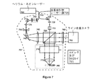
図7は、本発明に係る角度分解型のFD−OCT撮像システムの代表的な実施例の概略図を示している。この代表的なシステムは、波長掃引型供給源(波長掃引型レーザー源)705、干渉計707、及び対応する電子回路(コンピュータ及びデータ取得(DAQ)カード)785を有する画像捕捉カメラ(ライン走査カメラ)765といったような複数のモジュールを具備することが可能である。例えば、レーザー出力は、光を干渉計707の2つのアームに分割することが可能である光カプラ710に導くことが可能である。基準アームコリメータ725から供給されるコリメートされた光は、要素735、740及び745を有する円筒形レンズ望遠鏡に入射することが可能である。この円筒形レンズ望遠鏡は、ライン走査カメラ765の寸法にビームを拡張することが可能である。基準アーム内のコリメータ725の前に、距離が可変である自由空間カプラ712を配置することにより、基準アームの長さの調節を円滑に遂行することが可能である。サンプルアームコリメータ730からのコリメートされた光は、リニア偏光子755及びビームスプリッタ750を通してサンプルに導くことが可能であり、この場合に、上記の光は、サンプル780上に光の焦点を合わせる撮像オプティクス770、775に入射することが可能である。
FIG. 7 shows a schematic diagram of an exemplary embodiment of an angle-resolved FD-OCT imaging system according to the present invention. This representative system includes an image capture camera (line scan camera) having a swept source (wavelength swept laser source) 705, an
それぞれ、コリメータ725、730の前に設けられている偏光コントローラ715、720を配置することにより、波長掃引型供給源705の周波数レンジにわたってフリンジ変調(Fringe Modulation)を極大化することが可能である。撮像オプティクス770、775は、その軸が、干渉計707の面に平行であり、且つ、ビームスプリッタ750から入射するビームに垂直である検流計ミラー770と、サンプル780から1焦点距離に配置された合焦レンズ775とから構成されている。入射ビームは、検流計ミラー770の水平の中心及び垂直の中心に接触している。サンプル780から反射して戻った光は、ミラー770及び合焦レンズ775を介して戻ることが可能であり、次いで、ビームスプリッタ750において基準ビームと干渉することが可能である。この干渉光は、ライン走査カメラ765上に焦点を合わせる円筒形レンズ760に入射することが可能である。ヘリウム・ネオン(He−Ne)レーザー700からの光は、ファイバカプラ(光カプラ)710に注入することが可能であり、この光は、撮像処理手順においてガイドビームとして機能することが可能である。
By arranging the
ライン走査カメラ765からの信号は、データ取得(DAQ)ボード785のアナログ/デジタル(A/D)入力ポートに送信することが可能である。例えば、1つのエーライン(a-line)に対応する期間内において、DAQボード785は、m個のデータポイントをn回の露光から取得することが可能であり、ここで、mは、ライン走査カメラ765内の検出器の数であってよく、nは、1つのエーライン当たりにサンプリングされる周波数の数であってよい。エーライン取得速度は、ライン走査カメラの読み取り速度とnとの商として判定することが可能である。DAQボード785からの読み取りは、例えば、各々の読み取り期間の開始時点におけるライン走査カメラ765によるTTLトリガ信号を使用して周波数掃引型レーザー源(波長掃引型レーザー源)705に同期化することが可能である。
The signal from the
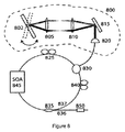
図8に示されているように、波長掃引型供給源の代表的な実施例は、利得要素としての半導体光学増幅器(Semiconductor Optical Amplifier:SOA)845と、検流計ミラーフィルタ800とを有するリング空洞レーザーとして構築可能であり、検流計ミラーフィルタは、検流計ミラー802、望遠鏡805、810、回折格子815、及びファイバコリメータ820を有することが可能である。2つの偏光コントローラ825、840を設けることにより、レーザーの偏光を最適化することが可能であり、これにより、出力カプラ835は、レーザー出力を提供している。出力カプラ835は、出力ポート836とレーザーポート837との間において、原則として光をほぼ等しく分割することが可能である。光サーキュレータ830は、偏光コントローラ840を介して、レーザーポート837から検流計ミラーフィルタ800に光を導くことが可能であり、且つ、検流計ミラーフィルタ800から戻ってきた光を、偏光コントローラ825を介してSOA845に導くことが可能である。検流計ミラーフィルタ800から反射される波長は、一般に、検流計ミラー802が回転するのに伴って変化する。光アイソレータ850を使用することにより、代表的なシステムの残りの部分からレーザーを分離することが可能である。
As shown in FIG. 8, a representative embodiment of a swept wavelength source is a ring having a semiconductor optical amplifier (SOA) 845 as a gain element and a
(方位角及び極角の分解のための二次元(2D)検出)
本発明の第2の代表的な実施例によれば、両方の次元が後方散乱光の角度別分布に対応している検出器の二次元アレイを使用して干渉光の検出を遂行することが可能である。サンプルに入射する光は、波長の調節が可能な狭いライン幅の供給源によって供給することが可能である。撮像サンプルから後方散乱した光は、2つの空間的次元に沿って拡張された基準ビームと干渉する。各々の検出器アレイ要素は、後方散乱光の極角及び方位角の固有のレンジに対応することが可能である。検出器アレイの読み取り値を取得しつつ、レーザーをその調節されたレンジにわたって掃引することにより、各々の離散した方位角及び極角の対毎のベクトルを取得することが可能である。フーリエドメイン光干渉断層撮影再構築法をベクトルに対して適用することが可能であり、これにより、深さ分解型の反射率プロファイルを生成することが可能である。アレイの読み取り値を取得しつつ、サンプルにわたってビームを走査することにより、又は、ビームに対してサンプルを移動させることにより、組織上の異なる場所における角度分解型の反射率プロファイルを取得することが可能である。これらのプロファイルを合成することにより、二次元又は三次元の断面反射率画像を形成することが可能である。
(Two-dimensional (2D) detection for azimuth and polar angle resolution)
According to a second exemplary embodiment of the present invention, interference light detection can be performed using a two-dimensional array of detectors, both dimensions corresponding to angular distributions of backscattered light. Is possible. The light incident on the sample can be supplied by a narrow line width source with adjustable wavelength. Light backscattered from the imaging sample interferes with a reference beam that is expanded along two spatial dimensions. Each detector array element can correspond to a unique range of polar and azimuthal angles of backscattered light. By taking a detector array reading and sweeping the laser over its adjusted range, it is possible to obtain a vector for each discrete azimuth and polar angle pair. A Fourier domain optical coherence tomography reconstruction method can be applied to the vectors, which can generate a depth-resolved reflectance profile. Acquire angle-resolved reflectance profiles at different locations on the tissue by scanning the beam across the sample or moving the sample relative to the beam while taking an array reading It is. By combining these profiles, it is possible to form a two-dimensional or three-dimensional cross-sectional reflectance image.
(角度及び波長の同時分解のための二次元(2D)検出)
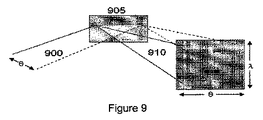
本発明の代表的な第3の実施例によれば、例えば、図9の動作図及びブロック図に示されているように、一方の次元が波長に対応しており、他方の次元が後方散乱光の角度に対応している検出器の二次元アレイを使用することにより、干渉光の検出を遂行することが可能である。サンプル上に入射する光は、広帯域供給源によって供給することが可能である。サンプルから後方散乱した光は、1つの空間次元に沿って拡張された基準ビームと干渉することが可能であり、この空間次元は、後方散乱光の角度に対応可能である。干渉光900は、回折格子905に入射することが可能であり、これにより、波長に対応する別の次元に沿って光を分離することが可能である。次いで、この分離された光910は、二次元検出器アレイ915に入射することが可能である。特定の後方散乱角度レンジに対応する検出器アレイの読み取りの各々の一次元部分に沿って、フーリエドメイン光干渉断層撮影再構築法を干渉スペクトルに対して適用することにより、深さ分解型の反射率プロファイルを提供することが可能である。アレイの読み取り値を取得しつつ、サンプルにわたってビームを走査することにより、又は、ビームに対してサンプルを移動させることにより、組織上の異なる地点における角度分解型の反射率プロファイルを取得することが可能である。これらのプロファイルを合成することにより、二次元又は三次元の断面反射率画像を形成することが可能である。
(Two-dimensional (2D) detection for simultaneous resolution of angles and wavelengths)
According to a third exemplary embodiment of the present invention, for example, one dimension corresponds to wavelength and the other dimension is backscattered, as shown in the operational diagram and block diagram of FIG. By using a two-dimensional array of detectors corresponding to the angle of light, it is possible to perform the detection of interference light. Light incident on the sample can be supplied by a broadband source. The light backscattered from the sample can interfere with a reference beam that is expanded along one spatial dimension, which can correspond to the angle of the backscattered light. The
(ファイバ束光学ブローブ)
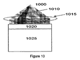
本発明に係る小さなプローブ形状を使用したアプリケーションに好適な第4の代表的な実施例は、図10の動作図及びブロック図に示されているように、ファイバ束と共に使用可能である。この代表的な実施例によれば、光ファイバのアレイ1025を使用することにより、撮像サンプル1000との間において光を送受信することが可能である。アレイ1025内の1つ又は複数のファイバは、「供給ファイバ(Delivery Fiber)」と呼ばれており、これらのファイバを通して、サンプル1000との間で光1010を送受信することが可能である。アレイ1025内の各々のファイバは、角度別後方散乱の固有の狭い角度レンジに対応可能である。ファイバの前に配置されているレンズ1020は、各々のファイバによって収集される光の量を増強するべく機能することが可能である。レンズ1020の前に配置されているレンズ1015は、サンプル1000上に光の焦点を合わせると共に、レンズ1020による収集の前にサンプル1000から後方散乱した光をコリメートするべく、機能している。
(Fiber bundle optical probe)
A fourth exemplary embodiment suitable for applications using small probe shapes according to the present invention can be used with fiber bundles, as shown in the operational and block diagrams of FIG. According to this exemplary embodiment, light can be transmitted to and received from the
(偏光感知式角度分解型のFD−OCT)
光干渉断層撮影法の環境における偏光計測は、生物学的な組織における複屈折の空間的な分解に有用であろう。本発明に係る第5の代表的な実施例によれば、次の各段階の中の1つ又は複数の段階を実行することにより、偏光計測を遂行することが可能である。
(Polarization-sensitive angle-resolved FD-OCT)
Polarimetry in an optical coherence tomography environment may be useful for the spatial resolution of birefringence in biological tissues. According to the fifth exemplary embodiment of the present invention, it is possible to perform polarization measurement by executing one or more of the following steps.
a)干渉計における受信の前に光の偏光を変化させる段階、並びに、基準アーム及び/又はサンプルアームの偏光状態を固定する段階
b)時間の関数としてサンプルビームのみの偏光を変化させる段階
c)時間の関数として基準ビームのみの偏光を変化させる段階
d)偏光状態が異なる基準ビームの少なくとも2つの特徴的な部分が存在可能なように、空間の関数として基準ビームの1つ又は複数の部分の偏光状態を変化させる段階
e)偏光状態が異なるサンプルビームの少なくとも2つの特徴的な部分が存在可能なように、基準ビームとの干渉の前に、空間の関数として後方散乱光の1つ又は複数の部分の偏光状態を変化させる段階
f)偏光状態が異なる少なくとも2つの特徴的な部分が存在可能なように、空間の関数として干渉光の1つ又は複数の部分の偏光状態を変化させる段階
a) changing the polarization of the light before reception at the interferometer and fixing the polarization state of the reference arm and / or the sample arm b) changing the polarization of the sample beam only as a function of time c) Changing the polarization of only the reference beam as a function of time d) of one or more parts of the reference beam as a function of space so that there can be at least two characteristic parts of the reference beam with different polarization states Changing the polarization state e) one or more of the backscattered light as a function of space prior to interference with the reference beam so that there can be at least two characteristic parts of the sample beam with different polarization states F) changing the polarization state of the part of the interference light as a function of space so that there can be at least two characteristic parts with different polarization states Step for changing the polarization state of the One or more portions
前述の典型的な手法(a)、(b)、及び/又は(c)を使用し、これらの手法が由来する偏光状態が恐らくは異なるように、異なる時点において受信されたエーラインを比較することにより、サンプルの複屈折マップを取得することが可能である。前述の典型的な手法(d)、(e)、及び/又は(f)を使用し、これらの手法が由来する偏光状態が恐らくは異なるように、異なる後方散乱角度レンジから得られたエーラインを比較することにより、サンプルの複屈折マップを取得することが可能である。 By using the above-mentioned typical techniques (a), (b), and / or (c), and comparing the lanes received at different times so that the polarization states from which these techniques are derived are probably different. It is possible to obtain a birefringence map of the sample. Use the typical methods (d), (e), and / or (f) described above to compare lanes obtained from different backscatter angle ranges so that the polarization states from which these methods are derived are probably different. By doing so, it is possible to obtain a birefringence map of the sample.
(粒子のサイジング)
平面波からのビームの逸脱を分析によって補償することができる場合には、ミー(Mie)散乱の演算フレームワークを使用し、角度分解型のFD−OCTシステム及び/又は方法から得られた角周波数コンテンツを分析することが可能である。具体的には、ミー(Mie)理論を使用して球面誘電散乱体から発生し得る角度別散乱分布を判定することが可能であることから、角度別散乱分布から散乱体のサイズ分布を判定するという逆の問題を遂行することが可能である。角度別後方散乱分布のミー散乱分析により、上皮組織内の散乱体分布の計測を実現させることが可能であり、この上皮組織内の散乱体分布を、癌病変に先行する形成不全遷移と相互に関連させることが可能である。
(Particle sizing)
Angular frequency content obtained from angle-resolved FD-OCT systems and / or methods using a Mie scattering computational framework where beam deviation from plane waves can be compensated by analysis Can be analyzed. Specifically, since it is possible to determine the scattering distribution by angle that can be generated from the spherical dielectric scatterer using Mie theory, the size distribution of the scatterer is determined from the scattering distribution by angle. It is possible to carry out the opposite problem. It is possible to measure scatterer distribution in epithelial tissue by Mie scattering analysis of backscatter distribution by angle, and this scatterer distribution in epithelial tissue can be correlated with dysplastic transition preceding cancer lesion. It can be related.
(角度別脱相関)
角度分解型のFD−OCTから取得した角度別後方散乱分布を処理する別の方法は、それらの角周波数コンテンツの分析を含んでいる。画像コントラストの尺度は、最大電力を有する角周波数ビン(Angular Frequency Bin)と、最大電力を有するピークの幅とを含む。角度別後方散乱分布の電力−スペクトル密度の分析は、ウィーナー・ヒンチン(Wiener-Kinchine)の定理による自動相関関数の分析と等価である。正規化された自動相関関数Cは、次の式(5)によって提供され得る。
(Decorrelation by angle)
Another method for processing angular backscatter distributions obtained from angle-resolved FD-OCT involves analysis of their angular frequency content. The measure of image contrast includes an angular frequency bin with maximum power and a peak width with maximum power. The analysis of the power-spectral density of the backscattering distribution by angle is equivalent to the analysis of the autocorrelation function by the Wiener-Kinchine theorem. The normalized autocorrelation function C can be provided by the following equation (5).
ここで、j及びiは、角度のインデックスであってよい。例えば、第1最小値との関係において計測された自動相関関数の中央ローブ(Central Lobe)の幅は、連続した角度別サンプル間における相関の程度を示すことが可能である。角度分解型のFD−OCTシステム及び方法を使用して取得した断面画像の各々のピクセル毎に上記の典型的な幅を判定することにより、角度別後方散乱分布の脱相関のレベルのコントラストを有する画像を提供することが可能である。 Here, j and i may be an angle index. For example, the width of the central lobe of the autocorrelation function measured in relation to the first minimum value can indicate the degree of correlation between consecutive angular samples. Determining the above typical width for each pixel of a cross-sectional image acquired using an angle-resolved FD-OCT system and method, thereby having a contrast at the level of decorrelation of the backscatter distribution by angle. An image can be provided.
(例)
スペックルを低減させるべく使用可能な本発明に係るシステム及び方法の代表的な実施例を以下の実験によって検証した。水溶性寒天ゲル(0.5重量%(パーセント)の寒天)及び直径0.3mmのポリマーミクロスフィア(Polymer Microsphere)(デューク サイアンティフィック(Duke Scientific)から入手)によって、2つのレイヤの組織ファントム(Phantom)を形成した。この組織ファントムをシリコーンアイソレータ(Silicone Isolator)(シグマ(Sigma)から入手)内に収容した。2mmの適切な深さを有する最初の散乱レイヤ(第1散乱レイヤ)を形成した。第1散乱レイヤよりも小さな散乱係数を有するように設計された第2散乱レイヤを第1散乱レイヤの上に形成した。この第2散乱レイヤは、約450mmの深さを有していた。深さとの関係において指数的な信号減衰を分析することにより、合計散乱係数は、第1レイヤ及び第2レイヤについて、それぞれ、24cm−1及び12cm−1と推定された。
(Example)
An exemplary embodiment of the system and method according to the present invention that can be used to reduce speckle was verified by the following experiment. A two layer tissue phantom (obtained from Duke Scientific) with a water soluble agar gel (0.5 wt% (percent) agar) and a 0.3 mm diameter polymer microsphere (obtained from Duke Scientific) Phantom). The tissue phantom was housed in a silicone isolator (obtained from Sigma). An initial scattering layer (first scattering layer) having an appropriate depth of 2 mm was formed. A second scattering layer designed to have a smaller scattering coefficient than the first scattering layer was formed on the first scattering layer. This second scattering layer had a depth of about 450 mm. By analyzing the exponential signal attenuation in relation to the depth, the total scattering coefficient, for the first and second layers, respectively, it was estimated to 24cm -1 and 12cm -1.
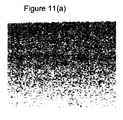
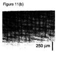
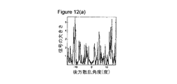
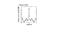
単一の角度別サンプルから生成された二次元画像は、図11(a)に示されているように、大きなスペックルを示しており、この場合には、2つのレイヤ間の境界は、明瞭な可視状態にはない。角度合成された画像内においては、スペックルが大幅に低減されており、図11(b)に示されているように、2つのレイヤの間の境界は、明瞭な可視状態にある。定性的な検査により、図11(b)の画像内の分解能が画像11(a)の画像内の分解能よりも大幅に低くなる可能性は高くない。ファントムの表面の下500mmの地点から取得した典型的な代表的角度別分布のグラフ及びこれに対応する自動相関関数が図12(a)及び図12(b)に示されている。 A two-dimensional image generated from a single angular sample shows large speckles as shown in FIG. 11 (a). In this case, the boundary between the two layers is clear. Is not visible. In the angle synthesized image, the speckle is greatly reduced, and the boundary between the two layers is in a clear visible state as shown in FIG. 11 (b). Due to the qualitative examination, the possibility that the resolution in the image of FIG. 11B is significantly lower than the resolution in the image of the image 11 (a) is not high. FIGS. 12A and 12B show typical typical angular distribution graphs obtained from a point 500 mm below the surface of the phantom and the corresponding autocorrelation function.
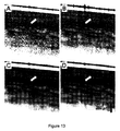
角度合成の効果は、図13A〜図13Dの画像に示されているように、食道組織に適用されたときに顕著に現れる。これらの画像は、生体外においてブタから得られたものであり、撮像対象のサンプルをカバースリップによって軽く圧縮することにより、上皮の基礎を成すレイヤの視認性を向上させている。具体的には、図13Aに示されているように、単一の角度別サンプルから生成された画像は、例えば、分解対象の特徴及びスペックルの結果としてもたらされる粒状性の観点において、最新技術の従来のOFDIシステムによって取得したものに質的に類似している。この典型的な画像においては、上皮内の散乱レイヤは、かすかに現れているのみである(矢印を参照されたい)。図13Bの画像に示されている3つの角度の合成の場合には、画像の特定の部分においてのみ、このレイヤが分解可能であるといったようなスペックルの低減レベルになっている。図13C及び図13Dの画像に示されている30個以上の角度の平均の場合には、散乱レイヤは、画像の長さにわたって明瞭に分解されている。角度合成によって実現される細部における同様の向上は、固有層及び上皮の基礎を成す粘膜下組織の領域内でも観察される。 The effect of angle synthesis is noticeable when applied to esophageal tissue, as shown in the images of FIGS. 13A-13D. These images are obtained from pigs in vitro, and the visibility of the layer that forms the basis of the epithelium is improved by lightly compressing the sample to be imaged with a cover slip. Specifically, as shown in FIG. 13A, an image generated from a single angular sample is a state-of-the-art technique, for example, in terms of granularity resulting from the features to be decomposed and speckle. Is qualitatively similar to that obtained by the conventional OFDI system. In this typical image, the scattering layer in the epithelium only appears faintly (see arrow). In the case of the synthesis of the three angles shown in the image of FIG. 13B, the speckle reduction level is such that this layer can be decomposed only in a specific part of the image. In the case of an average of 30 or more angles shown in the images of FIGS. 13C and 13D, the scattering layer is clearly resolved over the length of the image. Similar improvements in the details achieved by angular synthesis are also observed in the submucosa regions underlying the lamina propria and epithelium.
以上の内容は、本発明の原理を例示したものにすぎない。本願明細書の開示内容に鑑み、説明対象の実施例に対する様々な変更及び変形が当業者には明らかであろう。実際に、本発明の代表的な実施例に係る装置、システム、及び方法は、任意のOCTシステム、OFDIシステム、スペクトルドメインOCT(SD−OCT)システム、又はその他の撮像システムと共に、並びに、例えば、2004年9月8日付けで出願された国際特許出願第PCT/US2004/029148号、2005年11月2日付けで出願された米国特許出願第11/266,779号、及び2004年7月9日付けで出願された米国特許出願第10/501,276号に記述されているものと共に使用可能であり、これらの特許出願の内容は、本願明細書で言及することによって、その全ての内容が本願明細書に包含されている。従って、当業者であれば、本願明細書には明示的に図示及び説明されてはいないが、本発明の原理を実施し、且つ、本発明の精神及び範囲に属する多数のシステム、装置、及び方法を考え出すことが可能であることを理解されたい。更には、以上において、従来技術の知識は、上記の説明で引用することによって明確に包含されていない場合でも、その全ての内容が明示的に本願明細書に包含されている。以上において参照した全ての文献は、本願明細書で言及することによって、その全ての内容が本願明細書に包含されている。 The foregoing is merely illustrative of the principles of the present invention. Various modifications and variations to the described embodiments will be apparent to those skilled in the art in view of the disclosure herein. Indeed, an apparatus, system and method according to an exemplary embodiment of the present invention can be used with any OCT system, OFDI system, spectral domain OCT (SD-OCT) system, or other imaging system, and for example, International Patent Application No. PCT / US2004 / 029148, filed September 8, 2004, US Patent Application No. 11 / 266,779, filed November 2, 2005, and July 9, 2004. Can be used with those described in US patent application Ser. No. 10 / 501,276 filed on date, the contents of which are hereby incorporated by reference in their entirety. It is included in this specification. Accordingly, those skilled in the art will recognize that many systems, devices, and implementations of the principles of the present invention and that fall within the spirit and scope of the present invention are not explicitly shown and described herein. It should be understood that it is possible to come up with a method. Moreover, in the foregoing description, the entire contents of the prior art are expressly included in the present specification even if not explicitly included by reference in the above description. All the documents referred to above are incorporated in the present specification by referring to the present specification.
Claims (28)
前記第3電磁波の各々と関連付けられた信号を同時に検出するべく構成された少なくとも1つの第2構成部であって、この場合に、前記信号は、前記サンプル内の複数の深さにおける少なくとも1つのサンプルの情報と関連付けられており、且つ、この場合に、前記少なくとも1つの第2構成部は、前記第3電磁波の中の少なくとも1つのものを使用することにより、前記第3電磁波の別のものを利用する必要性を伴うことなしに、前記サンプル内の複数の深さを判定することが可能である、少なくとも1つの第2構成部とを有することを特徴とする装置。 At least one first component configured to receive at least one first electromagnetic wave and to transfer at least one second electromagnetic wave within a solid angle to the sample, wherein the at least one first component One second electromagnetic wave is associated with the at least one first electromagnetic wave, wherein the at least one first component comprises a plurality of samples from the sample associated with the at least one second electromagnetic wave. At least one first component configured to receive a third electromagnetic wave, wherein in this case at least one portion of the third electromagnetic wave is provided outside an outer edge of the solid angle; ,
At least one second component configured to simultaneously detect a signal associated with each of the third electromagnetic waves, wherein the signal is at least one at a plurality of depths in the sample. Associated with sample information, and in this case, the at least one second component uses another one of the third electromagnetic waves by using at least one of the third electromagnetic waves. Having at least one second component capable of determining a plurality of depths in the sample without the need to utilize
少なくとも1つの第1電磁波を受信する段階と、
立体角内の少なくとも1つの第2電磁波をサンプルに対して転送する段階であって、この場合に、前記少なくとも1つの第2電磁波は、前記少なくとも1つの第1電磁波と関連付けられている段階と、
前記少なくとも1つの第2電磁波と関連付けられた前記サンプルから複数の第3電磁波を受信する段階であって、この場合に、前記第3電磁波の少なくとも1つの部分は、前記立体角の外縁の外において提供されている段階と、
前記第3電磁波の各々と関連付けられた前記信号を同時に検出する段階であって、この場合に、前記信号は、前記サンプル内の複数の深さにおける前記少なくとも1つのサンプルの情報と関連付けられている段階と、
前記第3電磁波の中の少なくとも1つのものを使用することにより、前記第3電磁波の別のものを利用する必要性を伴うことなしに、前記サンプル内の複数の深さを判定する段階とを有することを特徴とする方法。 In a method for detecting a signal,
Receiving at least one first electromagnetic wave;
Transferring at least one second electromagnetic wave within a solid angle to the sample, wherein the at least one second electromagnetic wave is associated with the at least one first electromagnetic wave;
Receiving a plurality of third electromagnetic waves from the sample associated with the at least one second electromagnetic wave, wherein at least one portion of the third electromagnetic wave is outside an outer edge of the solid angle. Provided stages, and
Simultaneously detecting the signal associated with each of the third electromagnetic waves, wherein the signal is associated with information of the at least one sample at a plurality of depths in the sample. Stages,
Determining a plurality of depths in the sample by using at least one of the third electromagnetic waves without the need to utilize another of the third electromagnetic waves; A method characterized by comprising.
前記少なくとも1つのサンプルから提供された複数の電磁波の信号と関連付けられた第1情報を受信するべく構成された少なくとも1つの第1構成部であって、この場合に、前記電磁波の中の少なくとも第1のものは、第1軸に沿って提供されており、且つ、前記電磁波の中の少なくとも第2のものは、前記第1軸とは異なる第2軸に沿って提供されており、この場合に、前記第1情報の少なくとも1つの部分内の前記信号の各々のデータは、前記少なくとも1つのサンプル内の複数の深さのデータを含んでいる、少なくとも1つの第1構成部と、
前記第1情報の関数として、前記少なくとも1つのサンプルの画像の少なくとも1つの部分のコントラストデータと関連付けられた第2情報を生成するべく構成された少なくとも1つの第2構成部とを有することを特徴とする装置。 In an apparatus for providing data associated with at least one sample,
At least one first component configured to receive first information associated with signals of a plurality of electromagnetic waves provided from the at least one sample, wherein at least a first component of the electromagnetic waves One is provided along a first axis and at least a second one of the electromagnetic waves is provided along a second axis different from the first axis, in this case And at least one first component, wherein each data of the signal in at least one portion of the first information comprises a plurality of depth data in the at least one sample;
At least one second component configured to generate second information associated with contrast data of at least one portion of the image of the at least one sample as a function of the first information. Equipment.
前記少なくとも1つのサンプルから提供された複数の電磁波の信号と関連付けられた第1情報を受信する段階であって、この場合に、前記電磁波の中の少なくとも第1のものは、第1軸に沿って提供されており、且つ、前記電磁波の中の少なくとも第2のものは、前記第1軸とは異なる第2軸に沿って提供されており、この場合に、前記第1情報の少なくとも1つの部分内の前記信号の各々のデータは、前記少なくとも1つのサンプル内の複数の深さのデータを含んでいる段階と、
前記第1情報の関数として、前記少なくとも1つのサンプルの画像の少なくとも1つの部分のコントラストデータと関連付けられた第2情報を生成する段階とを有することを特徴とする方法。 In a method of providing data associated with at least one sample,
Receiving first information associated with signals of a plurality of electromagnetic waves provided from the at least one sample, wherein at least a first one of the electromagnetic waves is along a first axis. And at least a second one of the electromagnetic waves is provided along a second axis different from the first axis, wherein in this case at least one of the first information Each data of the signal in a portion includes a plurality of depth data in the at least one sample;
Generating second information associated with contrast data of at least one portion of the image of the at least one sample as a function of the first information.
前記第3電磁波の中の少なくとも2つのものと、前記少なくとも1つの第1電磁波と関連付けられた少なくとも1つの第4電磁波との間の干渉を検出するべく構成され、且つ、前記干渉に基づいて前記サンプル内の少なくとも1つの深さの関数として、前記サンプルと関連付けられた情報を取得するべく構成された少なくとも1つの第2構成部とを有することを特徴とする装置。 At least one first component configured to receive at least one first electromagnetic wave and transfer at least one second electromagnetic wave within a solid angle to the sample, wherein the at least one first component A second electromagnetic wave is associated with the at least one first electromagnetic wave, wherein the at least one first component is a plurality of third from the sample associated with the at least one second electromagnetic wave. Configured to receive at least two of the electromagnetic waves simultaneously, and in this case, at least one portion of the third electromagnetic wave is provided outside the outer edge of the solid angle, at least one Two first components;
Configured to detect interference between at least two of the third electromagnetic waves and at least one fourth electromagnetic wave associated with the at least one first electromagnetic wave, and based on the interference, the An apparatus comprising: at least one second component configured to obtain information associated with the sample as a function of at least one depth in the sample.
少なくとも1つの第1電磁波を受信する段階と、
立体角内の少なくとも1つの第2電磁波をサンプルに対して転送する段階であって、この場合に、前記少なくとも1つの第2電磁波は、前記少なくとも1つの第1電磁波と関連付けられている段階と、
前記少なくとも1つの第2電磁波と関連付けられた前記サンプルから複数の第3電磁波の中の少なくとも2つのものを同時に受信する段階であって、前記第3電磁波の少なくとも1つの部分は、前記立体角の外縁の外において提供されている段階と、
前記第3電磁波の中の少なくとも2つのものと、前記少なくとも1つの第1電磁波と関連付けられた少なくとも1つの第4電磁波との間の干渉を検出する段階と、
前記干渉に基づいて前記サンプル内の少なくとも1つの深さの関数として、前記サンプルと関連付けられた情報を取得する段階とを有することを特徴とする方法。 In a method for detecting a signal,
Receiving at least one first electromagnetic wave;
Transferring at least one second electromagnetic wave within a solid angle to the sample, wherein the at least one second electromagnetic wave is associated with the at least one first electromagnetic wave;
Simultaneously receiving at least two of a plurality of third electromagnetic waves from the sample associated with the at least one second electromagnetic wave, wherein at least one portion of the third electromagnetic wave is of the solid angle A stage provided outside the outer edge;
Detecting interference between at least two of the third electromagnetic waves and at least one fourth electromagnetic wave associated with the at least one first electromagnetic wave;
Obtaining information associated with the sample as a function of at least one depth in the sample based on the interference.
Applications Claiming Priority (2)
| Application Number | Priority Date | Filing Date | Title |
|---|---|---|---|
| US77654406P | 2006-02-24 | 2006-02-24 | |
| PCT/US2007/062465 WO2007101026A2 (en) | 2006-02-24 | 2007-02-21 | Methods and systems for performing angle-resolved fourier-domain optical coherence tomography |
Related Child Applications (2)
| Application Number | Title | Priority Date | Filing Date |
|---|---|---|---|
| JP2012248356A Division JP2013064747A (en) | 2006-02-24 | 2012-11-12 | Method and system for performing fourier domain optical coherence tomography of angle resolution type |
| JP2013205046A Division JP5856119B2 (en) | 2006-02-24 | 2013-09-30 | Method and system for performing angle-resolved Fourier domain optical coherence tomography |
Publications (2)
| Publication Number | Publication Date |
|---|---|
| JP2009527770A true JP2009527770A (en) | 2009-07-30 |
| JP2009527770A5 JP2009527770A5 (en) | 2010-04-08 |
Family
ID=38234475
Family Applications (4)
| Application Number | Title | Priority Date | Filing Date |
|---|---|---|---|
| JP2008556520A Pending JP2009527770A (en) | 2006-02-24 | 2007-02-21 | Method and system for performing angle-resolved Fourier domain optical coherence tomography |
| JP2012248356A Pending JP2013064747A (en) | 2006-02-24 | 2012-11-12 | Method and system for performing fourier domain optical coherence tomography of angle resolution type |
| JP2013205046A Expired - Fee Related JP5856119B2 (en) | 2006-02-24 | 2013-09-30 | Method and system for performing angle-resolved Fourier domain optical coherence tomography |
| JP2015123729A Expired - Fee Related JP5887006B2 (en) | 2006-02-24 | 2015-06-19 | Method and system for performing angle-resolved Fourier domain optical coherence tomography |
Family Applications After (3)
| Application Number | Title | Priority Date | Filing Date |
|---|---|---|---|
| JP2012248356A Pending JP2013064747A (en) | 2006-02-24 | 2012-11-12 | Method and system for performing fourier domain optical coherence tomography of angle resolution type |
| JP2013205046A Expired - Fee Related JP5856119B2 (en) | 2006-02-24 | 2013-09-30 | Method and system for performing angle-resolved Fourier domain optical coherence tomography |
| JP2015123729A Expired - Fee Related JP5887006B2 (en) | 2006-02-24 | 2015-06-19 | Method and system for performing angle-resolved Fourier domain optical coherence tomography |
Country Status (5)
| Country | Link |
|---|---|
| US (2) | US7982879B2 (en) |
| EP (4) | EP1987318B1 (en) |
| JP (4) | JP2009527770A (en) |
| CN (1) | CN101410691A (en) |
| WO (1) | WO2007101026A2 (en) |
Cited By (8)
| Publication number | Priority date | Publication date | Assignee | Title |
|---|---|---|---|---|
| JP2013518256A (en) * | 2010-01-22 | 2013-05-20 | デユーク・ユニバーシテイ | Multiple windowing scheme for spectroscopic coherence tomography (OCT) and Fourier domain low coherence interferometry |
| JP2016505828A (en) * | 2012-12-06 | 2016-02-25 | リーハイ・ユニバーシティー | Space-division multiplexed optical coherence tomography system |
| US9687157B2 (en) | 2005-10-11 | 2017-06-27 | Duke University | Systems and methods for endoscopic angle-resolved low coherence interferometry |
| US9823127B2 (en) | 2010-01-22 | 2017-11-21 | Duke University | Systems and methods for deep spectroscopic imaging of biological samples with use of an interferometer and spectrometer |
| WO2018203506A1 (en) * | 2017-05-01 | 2018-11-08 | キヤノン株式会社 | Optical coherence tomography apparatus |
| JP2019058644A (en) * | 2017-06-16 | 2019-04-18 | キヤノン ユーエスエイ, インコーポレイテッドCanon U.S.A., Inc | Radial line scanning spectrometer including two-dimensional sensor |
| JP2020073888A (en) * | 2012-06-26 | 2020-05-14 | ケーエルエー コーポレイション | Algorithmic removal of scanning and diffraction optical measurements in angle-resolved reflectance measurements |
| JP2023063161A (en) * | 2021-10-22 | 2023-05-09 | 住友金属鉱山株式会社 | How to predict reflectance, how to select the best material |
Families Citing this family (55)
| Publication number | Priority date | Publication date | Assignee | Title |
|---|---|---|---|---|
| US7324214B2 (en) | 2003-03-06 | 2008-01-29 | Zygo Corporation | Interferometer and method for measuring characteristics of optically unresolved surface features |
| US7102758B2 (en) | 2003-05-06 | 2006-09-05 | Duke University | Fourier domain low-coherence interferometry for light scattering spectroscopy apparatus and method |
| DE602006008896D1 (en) * | 2005-01-20 | 2009-10-15 | Zygo Corp | INTERFEROMETER FOR DETERMINING PROPERTIES OF AN OBJECT SURFACE |
| ES2541851T3 (en) * | 2005-10-11 | 2015-07-27 | Duke University | Systems and method for endoscopic interferometry of low coherence resolved at fiber-based angle |
| US8131348B2 (en) * | 2006-05-12 | 2012-03-06 | Northshore University Healthsystem | Systems, methods and apparatuses of elastic light scattering spectroscopy and low coherence enhanced backscattering spectroscopy |
| CA2651799C (en) * | 2006-05-12 | 2016-07-19 | Northwestern University | Systems, methods, and apparatuses of low-coherence enhanced backscattering spectroscopy |
| MX2009000407A (en) * | 2006-07-21 | 2009-03-25 | Oncoscope Inc | Protective probe tip, particularly for use on a fiber-optic probe used in an endoscopic application. |
| JP5744403B2 (en) * | 2006-08-11 | 2015-07-08 | ノースウェスタン ユニバーシティ | Method for identifying target refractive index variation |
| AU2008298551A1 (en) * | 2007-09-13 | 2009-03-19 | Duke University | Apparatuses, systems, and methods for low-coherence interferometry (LCI) |
| US20090177094A1 (en) * | 2008-01-08 | 2009-07-09 | Oncoscope, Inc. | Systems and methods for tissue examination, diagnostic, treatment, and/or monitoring |
| DE102008017740A1 (en) * | 2008-04-07 | 2009-10-15 | Lios Technology Gmbh | Apparatus and method for calibrating a fiber optic temperature measuring system |
| JP5306075B2 (en) * | 2008-07-07 | 2013-10-02 | キヤノン株式会社 | Imaging apparatus and imaging method using optical coherence tomography |
| US9885834B2 (en) | 2009-01-08 | 2018-02-06 | Northwestern University | Probe apparatus for measuring depth-limited properties with low-coherence enhanced backscattering |
| CZ302803B6 (en) * | 2009-02-04 | 2011-11-16 | Univerzita Palackého | Detection method of coherence granularity field movement and apparatus for making the same |
| US8928892B2 (en) * | 2009-03-04 | 2015-01-06 | Elie Meimoun | Wavefront analysis inspection apparatus and method |
| JP5808119B2 (en) * | 2010-04-13 | 2015-11-10 | キヤノン株式会社 | Model eye, method for adjusting optical tomographic imaging apparatus, and evaluation method |
| US11105686B2 (en) | 2010-05-10 | 2021-08-31 | University of Pittshurgh-Of the Commonwealth System of Higher Education | Spatial-domain low-coherence quantitative phase microscopy |
| EP2577272A4 (en) * | 2010-05-24 | 2017-10-25 | Fairfield University | Low coherence enhanced backscattering tomography and techniques |
| US20120050746A1 (en) * | 2010-08-29 | 2012-03-01 | Shivani Sharma | Apparatus and method for increasing depth range and signal to noise ratio in fourier domain low coherence interferometry |
| JP5588291B2 (en) * | 2010-09-29 | 2014-09-10 | キヤノン株式会社 | Information processing apparatus, information processing method, information processing system, and program |
| WO2013022986A1 (en) * | 2011-08-09 | 2013-02-14 | Optovue, Inc. | Motion correction and normalization of features in optical coherence tomography |
| EP2565625A1 (en) * | 2011-09-05 | 2013-03-06 | Ludwig-Maximilians-Universität München | Optical measurement system and method for operating an optical measurement system |
| CN102506917A (en) * | 2011-12-03 | 2012-06-20 | 太原理工大学 | Optical fiber sensing device for optical fiber chaos laser device and method thereof |
| US9335486B2 (en) * | 2012-01-20 | 2016-05-10 | Afl Telecommunications Llc | Method and apparatus for aligning a large diameter optical fiber |
| US9541375B2 (en) | 2012-07-20 | 2017-01-10 | Samsung Electronics Co., Ltd. | Method and apparatus for generating tomography images |
| EP2929327B1 (en) | 2012-12-05 | 2019-08-14 | Perimeter Medical Imaging, Inc. | System and method for wide field oct imaging |
| HK1210827A1 (en) * | 2012-12-06 | 2016-05-06 | 周超 | System and method for parallel imaging optical coherence tomography |
| US9335154B2 (en) * | 2013-02-01 | 2016-05-10 | Duke University | Systems and methods of angle-resolved low coherence interferometry based optical correlation |
| CA2904894C (en) * | 2013-03-13 | 2021-07-27 | Optimedica Corporation | Free floating support for laser eye surgery system |
| CN107456313B (en) | 2013-03-13 | 2020-11-17 | 光学医疗公司 | Free floating patient interface for laser surgery system |
| WO2015089308A1 (en) * | 2013-12-11 | 2015-06-18 | The General Hospital Corporation | Apparatus and method for high-speed full field optical coherence microscopy |
| US20170219485A1 (en) * | 2014-10-01 | 2017-08-03 | Purdue Research Foundation | Organism Identification |
| CN104330104B (en) * | 2014-10-31 | 2017-04-12 | 浙江大学 | Measuring device for interferential sensor arm length difference |
| JP2016151524A (en) * | 2015-02-18 | 2016-08-22 | ソニー株式会社 | Speckle imaging device, speckle imaging system, and speckle imaging method |
| US9984459B2 (en) | 2015-04-15 | 2018-05-29 | Kabushiki Kaisha Topcon | OCT angiography calculation with optimized signal processing |
| JP6869951B2 (en) | 2015-04-16 | 2021-05-12 | ジェンテュイティ・リミテッド・ライアビリティ・カンパニーGentuity, LLC | Imaging system |
| EP4675259A2 (en) | 2015-08-31 | 2026-01-07 | Spryte Medical, Inc. | Imaging system includes imaging probe and delivery devices |
| DE102017115922C5 (en) * | 2017-07-14 | 2023-03-23 | Precitec Gmbh & Co. Kg | Method and device for measuring and setting a distance between a machining head and a workpiece and associated method for regulation |
| EP3655748B1 (en) | 2017-07-18 | 2023-08-09 | Perimeter Medical Imaging, Inc. | Sample container for stabilizing and aligning excised biological tissue samples for ex vivo analysis |
| TW201921023A (en) * | 2017-09-18 | 2019-06-01 | 安盟生技股份有限公司 | Interference objective module and optical device and method using the same |
| US20190101489A1 (en) * | 2017-09-29 | 2019-04-04 | Michael John Darwin | Method and Apparatus for Simultaneously Measuring 3Dimensional Structures and Spectral Content of Said Structures |
| US10856780B2 (en) * | 2017-11-09 | 2020-12-08 | Joshua Noel Hogan | Spoof detection for biometric validation |
| JP7160935B2 (en) | 2017-11-28 | 2022-10-25 | ジェンテュイティ・リミテッド・ライアビリティ・カンパニー | Imaging system |
| GB201803523D0 (en) * | 2018-03-05 | 2018-04-18 | Malvern Panalytical Ltd | Improved particle sizing by optical diffraction |
| EP3841736A4 (en) | 2018-09-17 | 2022-05-18 | Gentuity LLC | IMAGING SYSTEM WITH OPTICAL PATH |
| EP3962346A4 (en) | 2019-04-30 | 2023-04-19 | Gentuity LLC | IMAGING PROBE WITH FLUID PRESSURE ELEMENT |
| EP3972477A4 (en) | 2019-05-21 | 2023-05-24 | Gentuity LLC | SYSTEMS AND METHODS FOR OCT-BASED PATIENT TREATMENT |
| CN112075925A (en) * | 2020-09-21 | 2020-12-15 | 北京脑科学与类脑研究中心 | Fluorescent imaging illumination device, imaging system and imaging method based on speckle principle |
| US12171524B2 (en) * | 2021-01-29 | 2024-12-24 | Duke University | Devices, systems, and methods for imaging in certain endoscopic environments |
| CN113237842A (en) * | 2021-04-25 | 2021-08-10 | 哈尔滨工业大学 | Fourier infrared spectrometer sample rack and using method |
| US12076118B2 (en) | 2021-10-01 | 2024-09-03 | Canon U.S.A., Inc. | Devices, systems, and methods for detecting external elastic lamina (EEL) from intravascular OCT images |
| US20220117524A1 (en) * | 2021-12-25 | 2022-04-21 | Pai-Chang Yeh | Apparatus, method and device for non-contact and non-invasive blood sugar monitoring to help monitor diabetic patients and hypercoagulation |
| CN115112572B (en) * | 2022-07-15 | 2024-04-26 | 首都师范大学 | Automatic testing device for micro-area angle resolution poincare sphere |
| CN116725492B (en) * | 2023-07-11 | 2023-12-12 | 江苏金视传奇科技有限公司 | Blood vessel imaging method and system based on optical coherence tomography |
| KR20250024355A (en) * | 2023-08-11 | 2025-02-18 | 주식회사 토모큐브 | System and method for high-resolution reflection tomographic imaging |
Citations (3)
| Publication number | Priority date | Publication date | Assignee | Title |
|---|---|---|---|---|
| JP2002517710A (en) * | 1998-06-02 | 2002-06-18 | ゼテティック・インスティチュート | Method and apparatus for confocal interference microscopy using wavenumber domain reflectometer and background amplitude reduction and compensation |
| WO2005047813A1 (en) * | 2003-10-27 | 2005-05-26 | The General Hospital Corporation | Method and apparatus for performing optical imaging using frequency-domain interferometry |
| WO2006017837A2 (en) * | 2004-08-06 | 2006-02-16 | The General Hospital Corporation | Process, system and software arrangement for determining at least one location in a sample using an optical coherence tomography |
Family Cites Families (668)
| Publication number | Priority date | Publication date | Assignee | Title |
|---|---|---|---|---|
| US188855A (en) * | 1877-03-27 | Improvement in can-jackets | ||
| US38040A (en) * | 1863-03-31 | Improvement in treating phosphatic guanos | ||
| US273777A (en) * | 1883-03-13 | Purifying water | ||
| US53673A (en) * | 1866-04-03 | Improved railway-frog | ||
| US86347A (en) * | 1869-02-02 | Improvement in the manufacture of tin-lined lead pipes | ||
| US236700A (en) * | 1881-01-18 | Machine for cleaning cotton | ||
| CA103769A (en) | 1906-11-16 | 1907-02-26 | Harvey S. Cover | Eye guard |
| US984888A (en) * | 1910-11-21 | 1911-02-21 | Johns H V Manville Co | Piston-packing expander. |
| US2339754A (en) * | 1941-03-04 | 1944-01-25 | Westinghouse Electric & Mfg Co | Supervisory apparatus |
| US3028114A (en) * | 1959-09-21 | 1962-04-03 | Kloeckner Werke Ag | Arrangement for coiling metal strip material |
| US3030816A (en) * | 1960-06-03 | 1962-04-24 | Specialties Dev Corp | Control device |
| US3090753A (en) | 1960-08-02 | 1963-05-21 | Exxon Research Engineering Co | Ester oil compositions containing acid anhydride |
| US3082105A (en) * | 1960-09-29 | 1963-03-19 | Bethlehem Steel Corp | Chrome silica brick |
| US3120137A (en) * | 1961-01-03 | 1964-02-04 | Ingersoll Rand Canada | Apparatus for forming varying shaped bores in hollow members |
| GB1257778A (en) | 1967-12-07 | 1971-12-22 | ||
| US3601480A (en) | 1968-07-10 | 1971-08-24 | Physics Int Co | Optical tunnel high-speed camera system |
| JPS4932484U (en) | 1972-06-19 | 1974-03-20 | ||
| US3872407A (en) * | 1972-09-01 | 1975-03-18 | Us Navy | Rapidly tunable laser |
| JPS584481Y2 (en) * | 1973-06-23 | 1983-01-26 | オリンパス光学工業株式会社 | Naishikiyoushiyahenkankogakkei |
| FR2253410A5 (en) | 1973-12-03 | 1975-06-27 | Inst Nat Sante Rech Med | |
| US4002650A (en) * | 1973-12-10 | 1977-01-11 | The Standard Oil Company (Ohio) | Preparation of maleic anhydride from n-butane |
| US4077949A (en) * | 1973-12-28 | 1978-03-07 | Sloan-Kettering Institute For Cancer Research | Polypeptide hormones of the thymus |
| US3941121A (en) | 1974-12-20 | 1976-03-02 | The University Of Cincinnati | Focusing fiber-optic needle endoscope |
| US3983507A (en) | 1975-01-06 | 1976-09-28 | Research Corporation | Tunable laser systems and method |
| US3973219A (en) | 1975-04-24 | 1976-08-03 | Cornell Research Foundation, Inc. | Very rapidly tuned cw dye laser |
| DE2601226C3 (en) * | 1976-01-14 | 1982-01-14 | Zahnradfabrik Friedrichshafen Ag, 7990 Friedrichshafen | Control device for the automotive control of the hydraulic variable displacement pump of a hydrostat |
| US4030831A (en) | 1976-03-22 | 1977-06-21 | The United States Of America As Represented By The Secretary Of The Navy | Phase detector for optical figure sensing |
| US4072200A (en) * | 1976-05-12 | 1978-02-07 | Morris Fred J | Surveying of subterranean magnetic bodies from an adjacent off-vertical borehole |
| US4141362A (en) | 1977-05-23 | 1979-02-27 | Richard Wolf Gmbh | Laser endoscope |
| US4224929A (en) | 1977-11-08 | 1980-09-30 | Olympus Optical Co., Ltd. | Endoscope with expansible cuff member and operation section |
| DE2964775D1 (en) | 1978-03-09 | 1983-03-24 | Nat Res Dev | Measurement of small movements |
| GB2030313A (en) | 1978-06-29 | 1980-04-02 | Wolf Gmbh Richard | Endoscopes |
| FR2448728A1 (en) | 1979-02-07 | 1980-09-05 | Thomson Csf | ROTATING JOINT DEVICE FOR OPTICAL CONDUCTOR CONNECTION AND SYSTEM COMPRISING SUCH A DEVICE |
| US4263843A (en) * | 1979-07-30 | 1981-04-28 | Aluminum Company Of America | Method and apparatus for controlled removal of excess slurry from organic foam |
| US4295738A (en) | 1979-08-30 | 1981-10-20 | United Technologies Corporation | Fiber optic strain sensor |
| US4300816A (en) | 1979-08-30 | 1981-11-17 | United Technologies Corporation | Wide band multicore optical fiber |
| US4428643A (en) | 1981-04-08 | 1984-01-31 | Xerox Corporation | Optical scanning system with wavelength shift correction |
| US5065331A (en) | 1981-05-18 | 1991-11-12 | Vachon Reginald I | Apparatus and method for determining the stress and strain in pipes, pressure vessels, structural members and other deformable bodies |
| GB2106736B (en) | 1981-09-03 | 1985-06-12 | Standard Telephones Cables Ltd | Optical transmission system |
| US4479499A (en) | 1982-01-29 | 1984-10-30 | Alfano Robert R | Method and apparatus for detecting the presence of caries in teeth using visible light |
| US5302025A (en) | 1982-08-06 | 1994-04-12 | Kleinerman Marcos Y | Optical systems for sensing temperature and other physical parameters |
| US4601036A (en) | 1982-09-30 | 1986-07-15 | Honeywell Inc. | Rapidly tunable laser |
| HU187188B (en) | 1982-11-25 | 1985-11-28 | Koezponti Elelmiszeripari | Device for generating radiation of controllable spectral structure |
| CH663466A5 (en) * | 1983-09-12 | 1987-12-15 | Battelle Memorial Institute | METHOD AND DEVICE FOR DETERMINING THE POSITION OF AN OBJECT IN RELATION TO A REFERENCE. |
| JPS6140633A (en) | 1984-08-02 | 1986-02-26 | Nec Corp | Tablet device |
| US4639999A (en) * | 1984-11-02 | 1987-02-03 | Xerox Corporation | High resolution, high efficiency I.R. LED printing array fabrication method |
| US4763977A (en) | 1985-01-09 | 1988-08-16 | Canadian Patents And Development Limited-Societe | Optical fiber coupler with tunable coupling ratio and method of making |
| EP0590268B1 (en) | 1985-03-22 | 1998-07-01 | Massachusetts Institute Of Technology | Fiber Optic Probe System for Spectrally Diagnosing Tissue |
| US5318024A (en) | 1985-03-22 | 1994-06-07 | Massachusetts Institute Of Technology | Laser endoscope for spectroscopic imaging |
| US4734578A (en) | 1985-03-27 | 1988-03-29 | Olympus Optical Co., Ltd. | Two-dimensional scanning photo-electric microscope |
| US4607622A (en) | 1985-04-11 | 1986-08-26 | Charles D. Fritch | Fiber optic ocular endoscope |
| US4631498A (en) | 1985-04-26 | 1986-12-23 | Hewlett-Packard Company | CW Laser wavemeter/frequency locking technique |
| US4650327A (en) * | 1985-10-28 | 1987-03-17 | Oximetrix, Inc. | Optical catheter calibrating assembly |
| JPH0664683B2 (en) | 1986-02-13 | 1994-08-22 | 松下電器産業株式会社 | Rotating magnetic head recorder |
| US5040889A (en) | 1986-05-30 | 1991-08-20 | Pacific Scientific Company | Spectrometer with combined visible and ultraviolet sample illumination |
| CA1290019C (en) | 1986-06-20 | 1991-10-01 | Hideo Kuwahara | Dual balanced optical signal receiver |
| US4770492A (en) | 1986-10-28 | 1988-09-13 | Spectran Corporation | Pressure or strain sensitive optical fiber |
| JPH0824665B2 (en) | 1986-11-28 | 1996-03-13 | オリンパス光学工業株式会社 | Endoscope device |
| US4744656A (en) | 1986-12-08 | 1988-05-17 | Spectramed, Inc. | Disposable calibration boot for optical-type cardiovascular catheter |
| US4751706A (en) | 1986-12-31 | 1988-06-14 | The United States Of America As Represented By The Secretary Of The Army | Laser for providing rapid sequence of different wavelengths |
| US4834111A (en) | 1987-01-12 | 1989-05-30 | The Trustees Of Columbia University In The City Of New York | Heterodyne interferometer |
| GB2209221B (en) | 1987-09-01 | 1991-10-23 | Litton Systems Inc | Hydrophone demodulator circuit and method |
| US5202931A (en) * | 1987-10-06 | 1993-04-13 | Cell Analysis Systems, Inc. | Methods and apparatus for the quantitation of nuclear protein |
| US4909631A (en) * | 1987-12-18 | 1990-03-20 | Tan Raul Y | Method for film thickness and refractive index determination |
| US4890901A (en) * | 1987-12-22 | 1990-01-02 | Hughes Aircraft Company | Color corrector for embedded prisms |
| US4892406A (en) | 1988-01-11 | 1990-01-09 | United Technologies Corporation | Method of and arrangement for measuring vibrations |
| FR2626367B1 (en) | 1988-01-25 | 1990-05-11 | Thomson Csf | MULTI-POINT FIBER OPTIC TEMPERATURE SENSOR |
| FR2626383B1 (en) | 1988-01-27 | 1991-10-25 | Commissariat Energie Atomique | EXTENDED FIELD SCAN AND DEPTH CONFOCAL OPTICAL MICROSCOPY AND DEVICES FOR CARRYING OUT THE METHOD |
| US4925302A (en) | 1988-04-13 | 1990-05-15 | Hewlett-Packard Company | Frequency locking device |
| US5730731A (en) * | 1988-04-28 | 1998-03-24 | Thomas J. Fogarty | Pressure-based irrigation accumulator |
| US4998972A (en) * | 1988-04-28 | 1991-03-12 | Thomas J. Fogarty | Real time angioscopy imaging system |
| US4905169A (en) * | 1988-06-02 | 1990-02-27 | The United States Of America As Represented By The United States Department Of Energy | Method and apparatus for simultaneously measuring a plurality of spectral wavelengths present in electromagnetic radiation |
| US5242437A (en) | 1988-06-10 | 1993-09-07 | Trimedyne Laser Systems, Inc. | Medical device applying localized high intensity light and heat, particularly for destruction of the endometrium |
| DE68929464T2 (en) | 1988-07-13 | 2003-11-20 | Optiscan Pty Ltd | scanning microscope |
| US5214538A (en) | 1988-07-25 | 1993-05-25 | Keymed (Medical And Industrial Equipment) Limited | Optical apparatus |
| GB8817672D0 (en) | 1988-07-25 | 1988-09-01 | Sira Ltd | Optical apparatus |
| US4868834A (en) | 1988-09-14 | 1989-09-19 | The United States Of America As Represented By The Secretary Of The Army | System for rapidly tuning a low pressure pulsed laser |
| DE3833602A1 (en) * | 1988-10-03 | 1990-02-15 | Krupp Gmbh | SPECTROMETER FOR SIMULTANEOUS INTENSITY MEASUREMENT IN DIFFERENT SPECTRAL AREAS |
| US4940328A (en) | 1988-11-04 | 1990-07-10 | Georgia Tech Research Corporation | Optical sensing apparatus and method |
| US4966589A (en) | 1988-11-14 | 1990-10-30 | Hemedix International, Inc. | Intravenous catheter placement device |
| ATE133545T1 (en) | 1988-12-21 | 1996-02-15 | Massachusetts Inst Technology | METHOD FOR LASER-INDUCED FLUORESCENCE OF TISSUE |
| US5046501A (en) | 1989-01-18 | 1991-09-10 | Wayne State University | Atherosclerotic identification |
| US5085496A (en) * | 1989-03-31 | 1992-02-04 | Sharp Kabushiki Kaisha | Optical element and optical pickup device comprising it |
| US5317389A (en) | 1989-06-12 | 1994-05-31 | California Institute Of Technology | Method and apparatus for white-light dispersed-fringe interferometric measurement of corneal topography |
| US4965599A (en) | 1989-11-13 | 1990-10-23 | Eastman Kodak Company | Scanning apparatus for halftone image screen writing |
| US5133035A (en) | 1989-11-14 | 1992-07-21 | Hicks John W | Multifiber endoscope with multiple scanning modes to produce an image free of fixed pattern noise |
| US4984888A (en) | 1989-12-13 | 1991-01-15 | Imo Industries, Inc. | Two-dimensional spectrometer |
| KR930003307B1 (en) | 1989-12-14 | 1993-04-24 | 주식회사 금성사 | Stereoscopic projector |
| US5251009A (en) | 1990-01-22 | 1993-10-05 | Ciba-Geigy Corporation | Interferometric measuring arrangement for refractive index measurements in capillary tubes |
| US5039193A (en) | 1990-04-03 | 1991-08-13 | Focal Technologies Incorporated | Fibre optic single mode rotary joint |
| JPH0456907A (en) | 1990-06-26 | 1992-02-24 | Fujikura Ltd | Optical fiber coupler |
| US5262644A (en) | 1990-06-29 | 1993-11-16 | Southwest Research Institute | Remote spectroscopy for raman and brillouin scattering |
| US5197470A (en) * | 1990-07-16 | 1993-03-30 | Eastman Kodak Company | Near infrared diagnostic method and instrument |
| GB9015793D0 (en) | 1990-07-18 | 1990-09-05 | Medical Res Council | Confocal scanning optical microscope |
| US5127730A (en) | 1990-08-10 | 1992-07-07 | Regents Of The University Of Minnesota | Multi-color laser scanning confocal imaging system |
| US5845639A (en) | 1990-08-10 | 1998-12-08 | Board Of Regents Of The University Of Washington | Optical imaging methods |
| JP3104984B2 (en) | 1990-09-27 | 2000-10-30 | オリンパス光学工業株式会社 | Optical scanning device for tomographic image observation |
| JPH04135551A (en) | 1990-09-27 | 1992-05-11 | Olympus Optical Co Ltd | Optical three-dimensional image observing device |
| US5305759A (en) | 1990-09-26 | 1994-04-26 | Olympus Optical Co., Ltd. | Examined body interior information observing apparatus by using photo-pulses controlling gains for depths |
| US5241364A (en) | 1990-10-19 | 1993-08-31 | Fuji Photo Film Co., Ltd. | Confocal scanning type of phase contrast microscope and scanning microscope |
| US5250186A (en) | 1990-10-23 | 1993-10-05 | Cetus Corporation | HPLC light scattering detector for biopolymers |
| US5202745A (en) * | 1990-11-07 | 1993-04-13 | Hewlett-Packard Company | Polarization independent optical coherence-domain reflectometry |
| US5275594A (en) * | 1990-11-09 | 1994-01-04 | C. R. Bard, Inc. | Angioplasty system having means for identification of atherosclerotic plaque |
| JP3035336B2 (en) * | 1990-11-27 | 2000-04-24 | 興和株式会社 | Blood flow measurement device |
| US5228001A (en) | 1991-01-23 | 1993-07-13 | Syracuse University | Optical random access memory |
| US5784162A (en) | 1993-08-18 | 1998-07-21 | Applied Spectral Imaging Ltd. | Spectral bio-imaging methods for biological research, medical diagnostics and therapy |
| US6198532B1 (en) | 1991-02-22 | 2001-03-06 | Applied Spectral Imaging Ltd. | Spectral bio-imaging of the eye |
| US5293872A (en) * | 1991-04-03 | 1994-03-15 | Alfano Robert R | Method for distinguishing between calcified atherosclerotic tissue and fibrous atherosclerotic tissue or normal cardiovascular tissue using Raman spectroscopy |
| US5321501A (en) | 1991-04-29 | 1994-06-14 | Massachusetts Institute Of Technology | Method and apparatus for optical imaging with means for controlling the longitudinal range of the sample |
| US6485413B1 (en) * | 1991-04-29 | 2002-11-26 | The General Hospital Corporation | Methods and apparatus for forward-directed optical scanning instruments |
| US5465147A (en) | 1991-04-29 | 1995-11-07 | Massachusetts Institute Of Technology | Method and apparatus for acquiring images using a ccd detector array and no transverse scanner |
| US5956355A (en) | 1991-04-29 | 1999-09-21 | Massachusetts Institute Of Technology | Method and apparatus for performing optical measurements using a rapidly frequency-tuned laser |
| US6564087B1 (en) | 1991-04-29 | 2003-05-13 | Massachusetts Institute Of Technology | Fiber optic needle probes for optical coherence tomography imaging |
| US6111645A (en) | 1991-04-29 | 2000-08-29 | Massachusetts Institute Of Technology | Grating based phase control optical delay line |
| US6501551B1 (en) | 1991-04-29 | 2002-12-31 | Massachusetts Institute Of Technology | Fiber optic imaging endoscope interferometer with at least one faraday rotator |
| US5748598A (en) | 1995-12-22 | 1998-05-05 | Massachusetts Institute Of Technology | Apparatus and methods for reading multilayer storage media using short coherence length sources |
| US6134003A (en) | 1991-04-29 | 2000-10-17 | Massachusetts Institute Of Technology | Method and apparatus for performing optical measurements using a fiber optic imaging guidewire, catheter or endoscope |
| US5441053A (en) | 1991-05-03 | 1995-08-15 | University Of Kentucky Research Foundation | Apparatus and method for multiple wavelength of tissue |
| US5281811A (en) * | 1991-06-17 | 1994-01-25 | Litton Systems, Inc. | Digital wavelength division multiplex optical transducer having an improved decoder |
| US5208651A (en) | 1991-07-16 | 1993-05-04 | The Regents Of The University Of California | Apparatus and method for measuring fluorescence intensities at a plurality of wavelengths and lifetimes |
| WO1993003672A1 (en) | 1991-08-20 | 1993-03-04 | Redd Douglas C B | Optical histochemical analysis, in vivo detection and real-time guidance for ablation of abnormal tissues using a raman spectroscopic detection system |
| DE4128744C1 (en) * | 1991-08-29 | 1993-04-22 | Siemens Ag, 8000 Muenchen, De | |
| US5177488A (en) | 1991-10-08 | 1993-01-05 | Hughes Aircraft Company | Programmable fiber optic delay line, and radar target simulation system incorporating the same |
| DE69218386T2 (en) | 1991-12-30 | 1997-09-04 | Philips Electronics Nv | Optical device and device provided with such an optical device for scanning an information level |
| US5353790A (en) | 1992-01-17 | 1994-10-11 | Board Of Regents, The University Of Texas System | Method and apparatus for optical measurement of bilirubin in tissue |
| US5212667A (en) | 1992-02-03 | 1993-05-18 | General Electric Company | Light imaging in a scattering medium, using ultrasonic probing and speckle image differencing |
| US5217456A (en) | 1992-02-24 | 1993-06-08 | Pdt Cardiovascular, Inc. | Device and method for intra-vascular optical radial imaging |
| US5248876A (en) | 1992-04-21 | 1993-09-28 | International Business Machines Corporation | Tandem linear scanning confocal imaging system with focal volumes at different heights |
| US5283795A (en) | 1992-04-21 | 1994-02-01 | Hughes Aircraft Company | Diffraction grating driven linear frequency chirped laser |
| US5486701A (en) * | 1992-06-16 | 1996-01-23 | Prometrix Corporation | Method and apparatus for measuring reflectance in two wavelength bands to enable determination of thin film thickness |
| US5411025A (en) | 1992-06-30 | 1995-05-02 | Cordis Webster, Inc. | Cardiovascular catheter with laterally stable basket-shaped electrode array |
| US5716324A (en) | 1992-08-25 | 1998-02-10 | Fuji Photo Film Co., Ltd. | Endoscope with surface and deep portion imaging systems |
| US5348003A (en) | 1992-09-03 | 1994-09-20 | Sirraya, Inc. | Method and apparatus for chemical analysis |
| EP0587514A1 (en) | 1992-09-11 | 1994-03-16 | Welch Allyn, Inc. | Processor module for video inspection probe |
| US5772597A (en) | 1992-09-14 | 1998-06-30 | Sextant Medical Corporation | Surgical tool end effector |
| US5698397A (en) | 1995-06-07 | 1997-12-16 | Sri International | Up-converting reporters for biological and other assays using laser excitation techniques |
| EP0787977B1 (en) | 1992-09-21 | 2004-05-06 | Institut National De La Sante Et De La Recherche Medicale (Inserm) | Intracorporal probe for precise determination of the velocity of a liquid, in particular of aortic flow |
| US5383467A (en) * | 1992-11-18 | 1995-01-24 | Spectrascience, Inc. | Guidewire catheter and apparatus for diagnostic imaging |
| DE69309953T2 (en) * | 1992-11-18 | 1997-09-25 | Spectrascience Inc | DIAGNOSTIC IMAGE DEVICE |
| US5785663A (en) | 1992-12-21 | 1998-07-28 | Artann Corporation | Method and device for mechanical imaging of prostate |
| US5400771A (en) | 1993-01-21 | 1995-03-28 | Pirak; Leon | Endotracheal intubation assembly and related method |
| JPH06222242A (en) | 1993-01-27 | 1994-08-12 | Shin Etsu Chem Co Ltd | Optical fiber coupler and manufacturing method thereof |
| US5987346A (en) | 1993-02-26 | 1999-11-16 | Benaron; David A. | Device and method for classification of tissue |
| US5414509A (en) | 1993-03-08 | 1995-05-09 | Associated Universities, Inc. | Optical pressure/density measuring means |
| JP3112595B2 (en) * | 1993-03-17 | 2000-11-27 | 安藤電気株式会社 | Optical fiber strain position measuring device using optical frequency shifter |
| FI93781C (en) | 1993-03-18 | 1995-05-26 | Wallac Oy | Biospecific multiparametric method of determination |
| US5485079A (en) | 1993-03-29 | 1996-01-16 | Matsushita Electric Industrial Co., Ltd. | Magneto-optical element and optical magnetic field sensor |
| DE4310209C2 (en) * | 1993-03-29 | 1996-05-30 | Bruker Medizintech | Optical stationary imaging in strongly scattering media |
| DE4314189C1 (en) | 1993-04-30 | 1994-11-03 | Bodenseewerk Geraetetech | Device for the examination of optical fibres made of glass by means of heterodyne Brillouin spectroscopy |
| SE501932C2 (en) | 1993-04-30 | 1995-06-26 | Ericsson Telefon Ab L M | Apparatus and method for dispersion compensation in a fiber optic transmission system |
| US5424827A (en) | 1993-04-30 | 1995-06-13 | Litton Systems, Inc. | Optical system and method for eliminating overlap of diffraction spectra |
| US5454807A (en) | 1993-05-14 | 1995-10-03 | Boston Scientific Corporation | Medical treatment of deeply seated tissue using optical radiation |
| EP0627643B1 (en) | 1993-06-03 | 1999-05-06 | Hamamatsu Photonics K.K. | Laser scanning optical system using axicon |
| JP3234353B2 (en) | 1993-06-15 | 2001-12-04 | 富士写真フイルム株式会社 | Tomographic information reader |
| US5840031A (en) | 1993-07-01 | 1998-11-24 | Boston Scientific Corporation | Catheters for imaging, sensing electrical potentials and ablating tissue |
| US5995645A (en) | 1993-08-18 | 1999-11-30 | Applied Spectral Imaging Ltd. | Method of cancer cell detection |
| US5803082A (en) | 1993-11-09 | 1998-09-08 | Staplevision Inc. | Omnispectramammography |
| US5983125A (en) | 1993-12-13 | 1999-11-09 | The Research Foundation Of City College Of New York | Method and apparatus for in vivo examination of subcutaneous tissues inside an organ of a body using optical spectroscopy |
| US5450203A (en) | 1993-12-22 | 1995-09-12 | Electroglas, Inc. | Method and apparatus for determining an objects position, topography and for imaging |
| US5411016A (en) | 1994-02-22 | 1995-05-02 | Scimed Life Systems, Inc. | Intravascular balloon catheter for use in combination with an angioscope |
| US5590660A (en) * | 1994-03-28 | 1997-01-07 | Xillix Technologies Corp. | Apparatus and method for imaging diseased tissue using integrated autofluorescence |
| DE4411017C2 (en) | 1994-03-30 | 1995-06-08 | Alexander Dr Knuettel | Optical stationary spectroscopic imaging in strongly scattering objects through special light focusing and signal detection of light of different wavelengths |
| TW275570B (en) * | 1994-05-05 | 1996-05-11 | Boehringer Mannheim Gmbh | |
| DE69531118D1 (en) | 1994-07-14 | 2003-07-24 | Washington Res Foundation Seat | DEVICE FOR DETECTING THE BARRETT METAPLASIA IN THE EYES |
| US5459325A (en) | 1994-07-19 | 1995-10-17 | Molecular Dynamics, Inc. | High-speed fluorescence scanner |
| US6159445A (en) | 1994-07-20 | 2000-12-12 | Nycomed Imaging As | Light imaging contrast agents |
| WO1996004839A1 (en) | 1994-08-08 | 1996-02-22 | Computed Anatomy, Incorporated | Processing of keratoscopic images using local spatial phase |
| ES2233727T3 (en) | 1994-08-18 | 2005-06-16 | Carl Zeiss Meditec Ag | SURGICAL DEVICE ASSISTED BY OPTICAL COHERENCE TOMOGRAPHY. |
| US5491524A (en) * | 1994-10-05 | 1996-02-13 | Carl Zeiss, Inc. | Optical coherence tomography corneal mapping apparatus |
| US5740808A (en) | 1996-10-28 | 1998-04-21 | Ep Technologies, Inc | Systems and methods for guilding diagnostic or therapeutic devices in interior tissue regions |
| US5817144A (en) | 1994-10-25 | 1998-10-06 | Latis, Inc. | Method for contemporaneous application OF laser energy and localized pharmacologic therapy |
| US6033721A (en) * | 1994-10-26 | 2000-03-07 | Revise, Inc. | Image-based three-axis positioner for laser direct write microchemical reaction |
| JPH08136345A (en) | 1994-11-10 | 1996-05-31 | Anritsu Corp | Double monochromator |
| JPH08160129A (en) | 1994-12-05 | 1996-06-21 | Uniden Corp | Speed detector |
| US5566267A (en) | 1994-12-15 | 1996-10-15 | Ceram Optec Industries Inc. | Flat surfaced optical fibers and diode laser medical delivery devices |
| US5600486A (en) * | 1995-01-30 | 1997-02-04 | Lockheed Missiles And Space Company, Inc. | Color separation microlens |
| US5648848A (en) | 1995-02-01 | 1997-07-15 | Nikon Precision, Inc. | Beam delivery apparatus and method for interferometry using rotatable polarization chucks |
| DE19506484C2 (en) | 1995-02-24 | 1999-09-16 | Stiftung Fuer Lasertechnologie | Method and device for selective non-invasive laser myography (LMG) |
| RU2100787C1 (en) * | 1995-03-01 | 1997-12-27 | Геликонов Валентин Михайлович | Fibre-optical interferometer and fiber-optical piezoelectric transducer |
| US5868731A (en) | 1996-03-04 | 1999-02-09 | Innotech Usa, Inc. | Laser surgical device and method of its use |
| WO1996028212A1 (en) | 1995-03-09 | 1996-09-19 | Innotech Usa, Inc. | Laser surgical device and method of its use |
| US5526338A (en) | 1995-03-10 | 1996-06-11 | Yeda Research & Development Co. Ltd. | Method and apparatus for storage and retrieval with multilayer optical disks |
| US5697373A (en) | 1995-03-14 | 1997-12-16 | Board Of Regents, The University Of Texas System | Optical method and apparatus for the diagnosis of cervical precancers using raman and fluorescence spectroscopies |
| US5735276A (en) | 1995-03-21 | 1998-04-07 | Lemelson; Jerome | Method and apparatus for scanning and evaluating matter |
| US5926592A (en) | 1995-03-24 | 1999-07-20 | Optiscan Pty Ltd | Optical fibre confocal imager with variable near-confocal control |
| US5565983A (en) | 1995-05-26 | 1996-10-15 | The Perkin-Elmer Corporation | Optical spectrometer for detecting spectra in separate ranges |
| US5785651A (en) | 1995-06-07 | 1998-07-28 | Keravision, Inc. | Distance measuring confocal microscope |
| US5621830A (en) | 1995-06-07 | 1997-04-15 | Smith & Nephew Dyonics Inc. | Rotatable fiber optic joint |
| WO1997001167A1 (en) | 1995-06-21 | 1997-01-09 | Massachusetts Institute Of Technology | Apparatus and method for accessing data on multilayered optical media |
| ATA107495A (en) | 1995-06-23 | 1996-06-15 | Fercher Adolf Friedrich Dr | COHERENCE BIOMETRY AND TOMOGRAPHY WITH DYNAMIC COHERENT FOCUS |
| US5829439A (en) | 1995-06-28 | 1998-11-03 | Hitachi Medical Corporation | Needle-like ultrasonic probe for ultrasonic diagnosis apparatus, method of producing same, and ultrasonic diagnosis apparatus using same |
| JP3654309B2 (en) | 1995-06-28 | 2005-06-02 | 株式会社日立メディコ | Acicular ultrasonic probe |
| US6104945A (en) | 1995-08-01 | 2000-08-15 | Medispectra, Inc. | Spectral volume microprobe arrays |
| WO1997008538A1 (en) * | 1995-08-24 | 1997-03-06 | Purdue Research Foundation | Fluorescence lifetime-based imaging and spectroscopy in tissues and other random media |
| US6016197A (en) * | 1995-08-25 | 2000-01-18 | Ceramoptec Industries Inc. | Compact, all-optical spectrum analyzer for chemical and biological fiber optic sensors |
| FR2738343B1 (en) | 1995-08-30 | 1997-10-24 | Cohen Sabban Joseph | OPTICAL MICROSTRATIGRAPHY DEVICE |
| US6763261B2 (en) | 1995-09-20 | 2004-07-13 | Board Of Regents, The University Of Texas System | Method and apparatus for detecting vulnerable atherosclerotic plaque |
| US6615071B1 (en) | 1995-09-20 | 2003-09-02 | Board Of Regents, The University Of Texas System | Method and apparatus for detecting vulnerable atherosclerotic plaque |
| JP2000511786A (en) | 1995-09-20 | 2000-09-12 | テキサス・ハート・インスティチュート | Detection of temperature difference in pipe wall |
| US5742419A (en) | 1995-11-07 | 1998-04-21 | The Board Of Trustees Of The Leland Stanford Junior Universtiy | Miniature scanning confocal microscope |
| US5719399A (en) * | 1995-12-18 | 1998-02-17 | The Research Foundation Of City College Of New York | Imaging and characterization of tissue based upon the preservation of polarized light transmitted therethrough |
| JP3699761B2 (en) | 1995-12-26 | 2005-09-28 | オリンパス株式会社 | Epifluorescence microscope |
| US5748318A (en) | 1996-01-23 | 1998-05-05 | Brown University Research Foundation | Optical stress generator and detector |
| US5840023A (en) | 1996-01-31 | 1998-11-24 | Oraevsky; Alexander A. | Optoacoustic imaging for medical diagnosis |
| US5642194A (en) | 1996-02-05 | 1997-06-24 | The Regents Of The University Of California | White light velocity interferometer |
| US5862273A (en) * | 1996-02-23 | 1999-01-19 | Kaiser Optical Systems, Inc. | Fiber optic probe with integral optical filtering |
| US5843000A (en) | 1996-05-07 | 1998-12-01 | The General Hospital Corporation | Optical biopsy forceps and method of diagnosing tissue |
| ATA84696A (en) * | 1996-05-14 | 1998-03-15 | Adolf Friedrich Dr Fercher | METHOD AND ARRANGEMENTS FOR INCREASING CONTRAST IN OPTICAL COHERENCE TOMOGRAPHY |
| US6020963A (en) * | 1996-06-04 | 2000-02-01 | Northeastern University | Optical quadrature Interferometer |
| US5795295A (en) | 1996-06-25 | 1998-08-18 | Carl Zeiss, Inc. | OCT-assisted surgical microscope with multi-coordinate manipulator |
| US5842995A (en) | 1996-06-28 | 1998-12-01 | Board Of Regents, The Univerisity Of Texas System | Spectroscopic probe for in vivo measurement of raman signals |
| US6296608B1 (en) | 1996-07-08 | 2001-10-02 | Boston Scientific Corporation | Diagnosing and performing interventional procedures on tissue in vivo |
| US6245026B1 (en) | 1996-07-29 | 2001-06-12 | Farallon Medsystems, Inc. | Thermography catheter |
| US6396941B1 (en) | 1996-08-23 | 2002-05-28 | Bacus Research Laboratories, Inc. | Method and apparatus for internet, intranet, and local viewing of virtual microscope slides |
| US5840075A (en) | 1996-08-23 | 1998-11-24 | Eclipse Surgical Technologies, Inc. | Dual laser device for transmyocardial revascularization procedures |
| US6544193B2 (en) | 1996-09-04 | 2003-04-08 | Marcio Marc Abreu | Noninvasive measurement of chemical substances |
| JPH1090603A (en) | 1996-09-18 | 1998-04-10 | Olympus Optical Co Ltd | Endscopic optical system |
| US5801831A (en) | 1996-09-20 | 1998-09-01 | Institute For Space And Terrestrial Science | Fabry-Perot spectrometer for detecting a spatially varying spectral signature of an extended source |
| RU2108122C1 (en) | 1996-09-24 | 1998-04-10 | Владимир Павлович Жаров | Method and device for physiotherapeutic irradiation with light |
| WO1998013715A1 (en) | 1996-09-27 | 1998-04-02 | Vincent Lauer | Microscope generating a three-dimensional representation of an object |
| DE19640495C2 (en) | 1996-10-01 | 1999-12-16 | Leica Microsystems | Device for confocal surface measurement |
| US5843052A (en) | 1996-10-04 | 1998-12-01 | Benja-Athon; Anuthep | Irrigation kit for application of fluids and chemicals for cleansing and sterilizing wounds |
| US5752518A (en) | 1996-10-28 | 1998-05-19 | Ep Technologies, Inc. | Systems and methods for visualizing interior regions of the body |
| US5904651A (en) | 1996-10-28 | 1999-05-18 | Ep Technologies, Inc. | Systems and methods for visualizing tissue during diagnostic or therapeutic procedures |
| US6044288A (en) * | 1996-11-08 | 2000-03-28 | Imaging Diagnostics Systems, Inc. | Apparatus and method for determining the perimeter of the surface of an object being scanned |
| US5872879A (en) | 1996-11-25 | 1999-02-16 | Boston Scientific Corporation | Rotatable connecting optical fibers |
| US6517532B1 (en) | 1997-05-15 | 2003-02-11 | Palomar Medical Technologies, Inc. | Light energy delivery head |
| US6437867B2 (en) | 1996-12-04 | 2002-08-20 | The Research Foundation Of The City University Of New York | Performing selected optical measurements with optical coherence domain reflectometry |
| US6249630B1 (en) | 1996-12-13 | 2001-06-19 | Imra America, Inc. | Apparatus and method for delivery of dispersion-compensated ultrashort optical pulses with high peak power |
| US5906759A (en) | 1996-12-26 | 1999-05-25 | Medinol Ltd. | Stent forming apparatus with stent deforming blades |
| US5871449A (en) * | 1996-12-27 | 1999-02-16 | Brown; David Lloyd | Device and method for locating inflamed plaque in an artery |
| US6272268B1 (en) | 1996-12-31 | 2001-08-07 | Corning Incorporated | Optical couplers with multilayer fibers |
| US5991697A (en) | 1996-12-31 | 1999-11-23 | The Regents Of The University Of California | Method and apparatus for optical Doppler tomographic imaging of fluid flow velocity in highly scattering media |
| US5760901A (en) | 1997-01-28 | 1998-06-02 | Zetetic Institute | Method and apparatus for confocal interference microscopy with background amplitude reduction and compensation |
| JP3213250B2 (en) | 1997-01-29 | 2001-10-02 | 株式会社生体光情報研究所 | Optical measurement device |
| US5801826A (en) | 1997-02-18 | 1998-09-01 | Williams Family Trust B | Spectrometric device and method for recognizing atomic and molecular signatures |
| US5836877A (en) | 1997-02-24 | 1998-11-17 | Lucid Inc | System for facilitating pathological examination of a lesion in tissue |
| US6120516A (en) | 1997-02-28 | 2000-09-19 | Lumend, Inc. | Method for treating vascular occlusion |
| US6010449A (en) * | 1997-02-28 | 2000-01-04 | Lumend, Inc. | Intravascular catheter system for treating a vascular occlusion |
| US5968064A (en) | 1997-02-28 | 1999-10-19 | Lumend, Inc. | Catheter system for treating a vascular occlusion |
| EP0971626A1 (en) | 1997-03-06 | 2000-01-19 | Massachusetts Institute Of Technology | Instrument for optically scanning of living tissue |
| CA2283949A1 (en) * | 1997-03-13 | 1998-09-17 | Haishan Zeng | Methods and apparatus for detecting the rejection of transplanted tissue |
| US6078047A (en) | 1997-03-14 | 2000-06-20 | Lucent Technologies Inc. | Method and apparatus for terahertz tomographic imaging |
| US5994690A (en) | 1997-03-17 | 1999-11-30 | Kulkarni; Manish D. | Image enhancement in optical coherence tomography using deconvolution |
| JPH10267631A (en) | 1997-03-26 | 1998-10-09 | Kowa Co | Optical measuring device |
| JPH10267830A (en) | 1997-03-26 | 1998-10-09 | Kowa Co | Optical measuring device |
| GB9707414D0 (en) | 1997-04-11 | 1997-05-28 | Imperial College | Anatomical probe |
| AU7221398A (en) | 1997-04-29 | 1998-11-24 | Nycomed Imaging As | Method of demarcating tissue |
| JP2001526650A (en) | 1997-04-29 | 2001-12-18 | ニユコメド・イメージング・アクシエセルカペト | Optical contrast agent |
| US6117128A (en) | 1997-04-30 | 2000-09-12 | Kenton W. Gregory | Energy delivery catheter and method for the use thereof |
| US5887009A (en) * | 1997-05-22 | 1999-03-23 | Optical Biopsy Technologies, Inc. | Confocal optical scanning system employing a fiber laser |
| US6002480A (en) | 1997-06-02 | 1999-12-14 | Izatt; Joseph A. | Depth-resolved spectroscopic optical coherence tomography |
| AU7711498A (en) * | 1997-06-02 | 1998-12-21 | Joseph A. Izatt | Doppler flow imaging using optical coherence tomography |
| US6208415B1 (en) * | 1997-06-12 | 2001-03-27 | The Regents Of The University Of California | Birefringence imaging in biological tissue using polarization sensitive optical coherent tomography |
| JP2002516586A (en) | 1997-06-23 | 2002-06-04 | ティーエイチエス インターナショナル,インコーポレイテッド | Method and apparatus for providing acoustic hemostasis |
| US5920390A (en) | 1997-06-26 | 1999-07-06 | University Of North Carolina | Fiberoptic interferometer and associated method for analyzing tissue |
| US6048349A (en) | 1997-07-09 | 2000-04-11 | Intraluminal Therapeutics, Inc. | Systems and methods for guiding a medical instrument through a body |
| US6058352A (en) | 1997-07-25 | 2000-05-02 | Physical Optics Corporation | Accurate tissue injury assessment using hybrid neural network analysis |
| US5921926A (en) | 1997-07-28 | 1999-07-13 | University Of Central Florida | Three dimensional optical imaging colposcopy |
| US5892583A (en) | 1997-08-21 | 1999-04-06 | Li; Ming-Chiang | High speed inspection of a sample using superbroad radiation coherent interferometer |
| US6014214A (en) * | 1997-08-21 | 2000-01-11 | Li; Ming-Chiang | High speed inspection of a sample using coherence processing of scattered superbroad radiation |
| US6069698A (en) | 1997-08-28 | 2000-05-30 | Olympus Optical Co., Ltd. | Optical imaging apparatus which radiates a low coherence light beam onto a test object, receives optical information from light scattered by the object, and constructs therefrom a cross-sectional image of the object |
| US6297018B1 (en) | 1998-04-17 | 2001-10-02 | Ljl Biosystems, Inc. | Methods and apparatus for detecting nucleic acid polymorphisms |
| US5920373A (en) | 1997-09-24 | 1999-07-06 | Heidelberg Engineering Optische Messysteme Gmbh | Method and apparatus for determining optical characteristics of a cornea |
| US5951482A (en) | 1997-10-03 | 1999-09-14 | Intraluminal Therapeutics, Inc. | Assemblies and methods for advancing a guide wire through body tissue |
| US6193676B1 (en) * | 1997-10-03 | 2001-02-27 | Intraluminal Therapeutics, Inc. | Guide wire assembly |
| US6091984A (en) | 1997-10-10 | 2000-07-18 | Massachusetts Institute Of Technology | Measuring tissue morphology |
| US5955737A (en) | 1997-10-27 | 1999-09-21 | Systems & Processes Engineering Corporation | Chemometric analysis for extraction of individual fluorescence spectrum and lifetimes from a target mixture |
| US6052186A (en) | 1997-11-05 | 2000-04-18 | Excel Precision, Inc. | Dual laser system for extended heterodyne interferometry |
| US6134010A (en) | 1997-11-07 | 2000-10-17 | Lucid, Inc. | Imaging system using polarization effects to enhance image quality |
| US6037579A (en) | 1997-11-13 | 2000-03-14 | Biophotonics Information Laboratories, Ltd. | Optical interferometer employing multiple detectors to detect spatially distorted wavefront in imaging of scattering media |
| US6107048A (en) | 1997-11-20 | 2000-08-22 | Medical College Of Georgia Research Institute, Inc. | Method of detecting and grading dysplasia in epithelial tissue |
| WO2000015101A1 (en) | 1998-09-11 | 2000-03-23 | Spectrx, Inc. | Multi-modal optical tissue diagnostic system |
| AU2242099A (en) | 1998-01-28 | 1999-08-16 | Ht Medical Systems, Inc. | Interface device and method for interfacing instruments to medical procedure simulation system |
| US6165170A (en) | 1998-01-29 | 2000-12-26 | International Business Machines Corporation | Laser dermablator and dermablation |
| US6831781B2 (en) | 1998-02-26 | 2004-12-14 | The General Hospital Corporation | Confocal microscopy with multi-spectral encoding and system and apparatus for spectroscopically encoded confocal microscopy |
| US6134033A (en) | 1998-02-26 | 2000-10-17 | Tyco Submarine Systems Ltd. | Method and apparatus for improving spectral efficiency in wavelength division multiplexed transmission systems |
| EP2267506A3 (en) | 1998-02-26 | 2011-03-02 | The General Hospital Corporation | Confocal microscopy with multi-spectral encoding |
| US6048742A (en) | 1998-02-26 | 2000-04-11 | The United States Of America As Represented By The Secretary Of The Air Force | Process for measuring the thickness and composition of thin semiconductor films deposited on semiconductor wafers |
| RU2148378C1 (en) | 1998-03-06 | 2000-05-10 | Геликонов Валентин Михайлович | Device for performing optic coherent tomography, optic fiber scanning device and method for diagnosing biological tissue in vivo |
| US6174291B1 (en) | 1998-03-09 | 2001-01-16 | Spectrascience, Inc. | Optical biopsy system and methods for tissue diagnosis |
| US6066102A (en) | 1998-03-09 | 2000-05-23 | Spectrascience, Inc. | Optical biopsy forceps system and method of diagnosing tissue |
| US6151522A (en) | 1998-03-16 | 2000-11-21 | The Research Foundation Of Cuny | Method and system for examining biological materials using low power CW excitation raman spectroscopy |
| DE19814057B4 (en) | 1998-03-30 | 2009-01-02 | Carl Zeiss Meditec Ag | Arrangement for optical coherence tomography and coherence topography |
| US6384915B1 (en) | 1998-03-30 | 2002-05-07 | The Regents Of The University Of California | Catheter guided by optical coherence domain reflectometry |
| US6175669B1 (en) * | 1998-03-30 | 2001-01-16 | The Regents Of The Universtiy Of California | Optical coherence domain reflectometry guidewire |
| US6996549B2 (en) * | 1998-05-01 | 2006-02-07 | Health Discovery Corporation | Computer-aided image analysis |
| WO1999057507A1 (en) | 1998-05-01 | 1999-11-11 | Board Of Regents, The University Of Texas System | Method and apparatus for subsurface imaging |
| JPH11326826A (en) | 1998-05-13 | 1999-11-26 | Sony Corp | Lighting method and lighting device |
| US6053613A (en) | 1998-05-15 | 2000-04-25 | Carl Zeiss, Inc. | Optical coherence tomography with new interferometer |
| FR2778838A1 (en) | 1998-05-19 | 1999-11-26 | Koninkl Philips Electronics Nv | METHOD FOR DETECTING VARIATIONS IN ELASTICITY AND ECHOGRAPHIC APPARATUS FOR CARRYING OUT THIS METHOD |
| US5995223A (en) | 1998-06-01 | 1999-11-30 | Power; Joan Fleurette | Apparatus for rapid phase imaging interferometry and method therefor |
| JPH11352409A (en) | 1998-06-05 | 1999-12-24 | Olympus Optical Co Ltd | Fluorescence detector |
| US6549801B1 (en) | 1998-06-11 | 2003-04-15 | The Regents Of The University Of California | Phase-resolved optical coherence tomography and optical doppler tomography for imaging fluid flow in tissue with fast scanning speed and high velocity sensitivity |
| AU5101699A (en) | 1998-07-15 | 2000-02-07 | Corazon Technologies, Inc. | Methods and devices for reducing the mineral content of vascular calcified lesions |
| US6166373A (en) | 1998-07-21 | 2000-12-26 | The Institute For Technology Development | Focal plane scanner with reciprocating spatial window |
| JP2000046729A (en) | 1998-07-31 | 2000-02-18 | Takahisa Mitsui | Apparatus and method for high-speed measurement of optical topographic image by using wavelength dispersion |
| JP2000068862A (en) * | 1998-08-19 | 2000-03-03 | Fujitsu Ltd | Error correction coding device |
| US20040140130A1 (en) | 1998-08-31 | 2004-07-22 | Halliburton Energy Services, Inc., A Delaware Corporation | Roller-cone bits, systems, drilling methods, and design methods with optimization of tooth orientation |
| US6741884B1 (en) | 1998-09-03 | 2004-05-25 | Hypermed, Inc. | Infrared endoscopic balloon probes |
| US8024027B2 (en) | 1998-09-03 | 2011-09-20 | Hyperspectral Imaging, Inc. | Infrared endoscopic balloon probes |
| JP2000131222A (en) | 1998-10-22 | 2000-05-12 | Olympus Optical Co Ltd | Optical tomographic imaging system |
| AU6417599A (en) | 1998-10-08 | 2000-04-26 | University Of Kentucky Research Foundation, The | Methods and apparatus for (in vivo) identification and characterization of vulnerable atherosclerotic plaques |
| JP2000121961A (en) | 1998-10-13 | 2000-04-28 | Olympus Optical Co Ltd | Confocal optical scanning probe system |
| US6274871B1 (en) | 1998-10-22 | 2001-08-14 | Vysis, Inc. | Method and system for performing infrared study on a biological sample |
| US6324419B1 (en) | 1998-10-27 | 2001-11-27 | Nejat Guzelsu | Apparatus and method for non-invasive measurement of stretch |
| JP2000126116A (en) | 1998-10-28 | 2000-05-09 | Olympus Optical Co Ltd | Photo-diagnosis system |
| US6524249B2 (en) | 1998-11-11 | 2003-02-25 | Spentech, Inc. | Doppler ultrasound method and apparatus for monitoring blood flow and detecting emboli |
| WO2000030225A1 (en) | 1998-11-13 | 2000-05-25 | Research And Development Institute, Inc. | Programmable frequency reference for laser frequency stabilization, and arbitrary optical clock generator, using persistent spectral hole burning |
| DE69932485T2 (en) | 1998-11-20 | 2007-01-11 | Fuji Photo Film Co. Ltd., Minamiashigara | Blood vessel imaging system |
| US5975697A (en) | 1998-11-25 | 1999-11-02 | Oti Ophthalmic Technologies, Inc. | Optical mapping apparatus with adjustable depth resolution |
| US6193352B1 (en) * | 1998-12-03 | 2001-02-27 | Eastman Kodak Company | Method for cleaning an ink jet print head |
| US6352502B1 (en) | 1998-12-03 | 2002-03-05 | Lightouch Medical, Inc. | Methods for obtaining enhanced spectroscopic information from living tissue, noninvasive assessment of skin condition and detection of skin abnormalities |
| RU2149464C1 (en) | 1999-01-19 | 2000-05-20 | Таганрогский государственный радиотехнический университет | Dynamic memory unit for storage of radio signals |
| US6191862B1 (en) | 1999-01-20 | 2001-02-20 | Lightlab Imaging, Llc | Methods and apparatus for high speed longitudinal scanning in imaging systems |
| US6272376B1 (en) | 1999-01-22 | 2001-08-07 | Cedars-Sinai Medical Center | Time-resolved, laser-induced fluorescence for the characterization of organic material |
| US6445944B1 (en) | 1999-02-01 | 2002-09-03 | Scimed Life Systems | Medical scanning system and related method of scanning |
| US6615072B1 (en) | 1999-02-04 | 2003-09-02 | Olympus Optical Co., Ltd. | Optical imaging device |
| US6185271B1 (en) * | 1999-02-16 | 2001-02-06 | Richard Estyn Kinsinger | Helical computed tomography with feedback scan control |
| DE19908883A1 (en) | 1999-03-02 | 2000-09-07 | Rainer Heintzmann | Process for increasing the resolution of optical imaging |
| US20070048818A1 (en) | 1999-03-12 | 2007-03-01 | Human Genome Sciences, Inc. | Human secreted proteins |
| CA2367804A1 (en) | 1999-03-29 | 2000-10-05 | Mark A. Hamm | Single mode optical fiber coupling systems |
| US6859275B2 (en) | 1999-04-09 | 2005-02-22 | Plain Sight Systems, Inc. | System and method for encoded spatio-spectral information processing |
| US6264610B1 (en) | 1999-05-05 | 2001-07-24 | The University Of Connecticut | Combined ultrasound and near infrared diffused light imaging system |
| US6353693B1 (en) * | 1999-05-31 | 2002-03-05 | Sanyo Electric Co., Ltd. | Optical communication device and slip ring unit for an electronic component-mounting apparatus |
| US6993170B2 (en) | 1999-06-23 | 2006-01-31 | Icoria, Inc. | Method for quantitative analysis of blood vessel structure |
| JP2001004447A (en) | 1999-06-23 | 2001-01-12 | Yokogawa Electric Corp | Spectroscope |
| US6611833B1 (en) | 1999-06-23 | 2003-08-26 | Tissueinformatics, Inc. | Methods for profiling and classifying tissue using a database that includes indices representative of a tissue population |
| US6208887B1 (en) * | 1999-06-24 | 2001-03-27 | Richard H. Clarke | Catheter-delivered low resolution Raman scattering analyzing system for detecting lesions |
| US7426409B2 (en) | 1999-06-25 | 2008-09-16 | Board Of Regents, The University Of Texas System | Method and apparatus for detecting vulnerable atherosclerotic plaque |
| GB9915082D0 (en) * | 1999-06-28 | 1999-08-25 | Univ London | Optical fibre probe |
| US6359692B1 (en) | 1999-07-09 | 2002-03-19 | Zygo Corporation | Method and system for profiling objects having multiple reflective surfaces using wavelength-tuning phase-shifting interferometry |
| JP2003504627A (en) | 1999-07-13 | 2003-02-04 | クロマビジョン メディカル システムズ インコーポレイテッド | Automatic detection of objects in biological samples |
| EP1199986B1 (en) | 1999-07-30 | 2005-06-01 | Boston Scientific Limited | Rotational and translational drive coupling for catheter assembly |
| ES2279767T3 (en) | 1999-07-30 | 2007-09-01 | Ceramoptec Gmbh | DOUBLE LENGTH MEDICAL DIODE LASER SYSTEM. |
| JP2001046321A (en) | 1999-08-09 | 2001-02-20 | Asahi Optical Co Ltd | Endoscope device |
| US6445939B1 (en) | 1999-08-09 | 2002-09-03 | Lightlab Imaging, Llc | Ultra-small optical probes, imaging optics, and methods for using same |
| US6725073B1 (en) | 1999-08-17 | 2004-04-20 | Board Of Regents, The University Of Texas System | Methods for noninvasive analyte sensing |
| JP3869589B2 (en) | 1999-09-02 | 2007-01-17 | ペンタックス株式会社 | Fiber bundle and endoscope apparatus |
| JP4464519B2 (en) | 2000-03-21 | 2010-05-19 | オリンパス株式会社 | Optical imaging device |
| US6687010B1 (en) * | 1999-09-09 | 2004-02-03 | Olympus Corporation | Rapid depth scanning optical imaging device |
| US6198956B1 (en) * | 1999-09-30 | 2001-03-06 | Oti Ophthalmic Technologies Inc. | High speed sector scanning apparatus having digital electronic control |
| JP2001174744A (en) | 1999-10-06 | 2001-06-29 | Olympus Optical Co Ltd | Optical scanning probe device |
| JP4363719B2 (en) | 1999-10-08 | 2009-11-11 | オリンパス株式会社 | Ultrasound-guided puncture system device |
| US6308092B1 (en) | 1999-10-13 | 2001-10-23 | C. R. Bard Inc. | Optical fiber tissue localization device |
| US6393312B1 (en) | 1999-10-13 | 2002-05-21 | C. R. Bard, Inc. | Connector for coupling an optical fiber tissue localization device to a light source |
| WO2001027679A1 (en) | 1999-10-15 | 2001-04-19 | Cellavision Ab | Microscope and method for manufacturing a composite image with a high resolution |
| US6538817B1 (en) * | 1999-10-25 | 2003-03-25 | Aculight Corporation | Method and apparatus for optical coherence tomography with a multispectral laser source |
| JP2001125009A (en) | 1999-10-28 | 2001-05-11 | Asahi Optical Co Ltd | Endoscope device |
| IL132687A0 (en) | 1999-11-01 | 2001-03-19 | Keren Mechkarim Ichilov Pnimit | System and method for evaluating body fluid samples |
| CN1409818A (en) | 1999-11-19 | 2003-04-09 | 乔宾伊冯公司 | Compact spectrofluorometer |
| DE50005933D1 (en) | 1999-11-24 | 2004-05-06 | Haag Streit Ag Koeniz | METHOD AND DEVICE FOR MEASURING OPTICAL PROPERTIES AT LEAST TWO AREAS DISTANCED FROM ONE OTHER IN A TRANSPARENT AND / OR DIFFUSIVE OBJECT |
| US7236637B2 (en) | 1999-11-24 | 2007-06-26 | Ge Medical Systems Information Technologies, Inc. | Method and apparatus for transmission and display of a compressed digitized image |
| JP2003516531A (en) | 1999-12-09 | 2003-05-13 | オーティーアイ オフサルミック テクノロジーズ インク | Optical mapping device with variable depth resolution |
| JP2001174404A (en) | 1999-12-15 | 2001-06-29 | Takahisa Mitsui | Apparatus and method for measuring optical tomographic image |
| US6738144B1 (en) | 1999-12-17 | 2004-05-18 | University Of Central Florida | Non-invasive method and low-coherence apparatus system analysis and process control |
| US6680780B1 (en) * | 1999-12-23 | 2004-01-20 | Agere Systems, Inc. | Interferometric probe stabilization relative to subject movement |
| US6445485B1 (en) | 2000-01-21 | 2002-09-03 | At&T Corp. | Micro-machine polarization-state controller |
| EP1251779A1 (en) | 2000-01-27 | 2002-10-30 | National Research Council of Canada | Visible-near infrared spectroscopy in burn injury assessment |
| JP3660185B2 (en) | 2000-02-07 | 2005-06-15 | 独立行政法人科学技術振興機構 | Tomographic image forming method and apparatus therefor |
| US6475210B1 (en) | 2000-02-11 | 2002-11-05 | Medventure Technology Corp | Light treatment of vulnerable atherosclerosis plaque |
| US6556305B1 (en) | 2000-02-17 | 2003-04-29 | Veeco Instruments, Inc. | Pulsed source scanning interferometer |
| US6618143B2 (en) | 2000-02-18 | 2003-09-09 | Idexx Laboratories, Inc. | High numerical aperture flow cytometer and method of using same |
| US6751490B2 (en) | 2000-03-01 | 2004-06-15 | The Board Of Regents Of The University Of Texas System | Continuous optoacoustic monitoring of hemoglobin concentration and hematocrit |
| US6687013B2 (en) | 2000-03-28 | 2004-02-03 | Hitachi, Ltd. | Laser interferometer displacement measuring system, exposure apparatus, and electron beam lithography apparatus |
| US6593101B2 (en) | 2000-03-28 | 2003-07-15 | Board Of Regents, The University Of Texas System | Enhancing contrast in biological imaging |
| US6567585B2 (en) | 2000-04-04 | 2003-05-20 | Optiscan Pty Ltd | Z sharpening for fibre confocal microscopes |
| US6692430B2 (en) * | 2000-04-10 | 2004-02-17 | C2Cure Inc. | Intra vascular imaging apparatus |
| AU2001259188A1 (en) | 2000-04-27 | 2001-11-07 | Iridex Corporation | Method and apparatus for real-time detection, control and recording of sub-clinical therapeutic laser lesions during ocular laser photocoagulation |
| US6711283B1 (en) | 2000-05-03 | 2004-03-23 | Aperio Technologies, Inc. | Fully automatic rapid microscope slide scanner |
| WO2001082786A2 (en) | 2000-05-03 | 2001-11-08 | Flock Stephen T | Optical imaging of subsurface anatomical structures and biomolecules |
| US6441959B1 (en) | 2000-05-19 | 2002-08-27 | Avanex Corporation | Method and system for testing a tunable chromatic dispersion, dispersion slope, and polarization mode dispersion compensator utilizing a virtually imaged phased array |
| US6301048B1 (en) | 2000-05-19 | 2001-10-09 | Avanex Corporation | Tunable chromatic dispersion and dispersion slope compensator utilizing a virtually imaged phased array |
| US6560259B1 (en) | 2000-05-31 | 2003-05-06 | Applied Optoelectronics, Inc. | Spatially coherent surface-emitting, grating coupled quantum cascade laser with unstable resonance cavity |
| US6975898B2 (en) | 2000-06-19 | 2005-12-13 | University Of Washington | Medical imaging, diagnosis, and therapy using a scanning single optical fiber system |
| JP4460117B2 (en) | 2000-06-29 | 2010-05-12 | 独立行政法人理化学研究所 | Grism |
| JP2002035005A (en) | 2000-07-21 | 2002-02-05 | Olympus Optical Co Ltd | Therapeutic device |
| US6757467B1 (en) | 2000-07-25 | 2004-06-29 | Optical Air Data Systems, Lp | Optical fiber system |
| US6441356B1 (en) | 2000-07-28 | 2002-08-27 | Optical Biopsy Technologies | Fiber-coupled, high-speed, angled-dual-axis optical coherence scanning microscopes |
| US6882432B2 (en) | 2000-08-08 | 2005-04-19 | Zygo Corporation | Frequency transform phase shifting interferometry |
| US6972894B2 (en) | 2000-08-11 | 2005-12-06 | Crystal Fibre A/S | Optical wavelength converter |
| US7625335B2 (en) | 2000-08-25 | 2009-12-01 | 3Shape Aps | Method and apparatus for three-dimensional optical scanning of interior surfaces |
| DE10042840A1 (en) | 2000-08-30 | 2002-03-14 | Leica Microsystems | Device and method for exciting fluorescence microscope markers in multiphoton scanning microscopy |
| WO2002021170A1 (en) | 2000-09-05 | 2002-03-14 | Arroyo Optics, Inc. | System and method for fabricating components of precise optical path length |
| JP2002095663A (en) | 2000-09-26 | 2002-04-02 | Fuji Photo Film Co Ltd | Method of acquiring optical tomographic image of sentinel lymph node and its device |
| JP2002113017A (en) | 2000-10-05 | 2002-04-16 | Fuji Photo Film Co Ltd | Laser treatment device |
| US7294333B1 (en) | 2000-10-20 | 2007-11-13 | Genegrafts Ltd. | Nucleic acid constructs and cells, and methods utilizing same for modifying the electrophysiological function of excitable tissues |
| ATE454845T1 (en) | 2000-10-30 | 2010-01-15 | Gen Hospital Corp | OPTICAL SYSTEMS FOR TISSUE ANALYSIS |
| JP3842101B2 (en) | 2000-10-31 | 2006-11-08 | 富士写真フイルム株式会社 | Endoscope device |
| ATE437350T1 (en) | 2000-10-31 | 2009-08-15 | Univ Danmarks Tekniske | OPTICAL AMPLIFICATION IN COHERENT OPTICAL FREQUENCY MODULATED CONTINUOUS REFLECTOMETRY |
| US6687036B2 (en) | 2000-11-03 | 2004-02-03 | Nuonics, Inc. | Multiplexed optical scanner technology |
| JP2002148185A (en) | 2000-11-08 | 2002-05-22 | Fuji Photo Film Co Ltd | Oct apparatus |
| US9295391B1 (en) | 2000-11-10 | 2016-03-29 | The General Hospital Corporation | Spectrally encoded miniature endoscopic imaging probe |
| WO2002038806A2 (en) | 2000-11-13 | 2002-05-16 | Gnothis Holding Sa | Detection of nucleic acid polymorphisms |
| US6665075B2 (en) | 2000-11-14 | 2003-12-16 | Wm. Marshurice University | Interferometric imaging system and method |
| DE10057539B4 (en) | 2000-11-20 | 2008-06-12 | Robert Bosch Gmbh | Interferometric measuring device |
| US6558324B1 (en) | 2000-11-22 | 2003-05-06 | Siemens Medical Solutions, Inc., Usa | System and method for strain image display |
| US6856712B2 (en) | 2000-11-27 | 2005-02-15 | University Of Washington | Micro-fabricated optical waveguide for use in scanning fiber displays and scanned fiber image acquisition |
| US7027633B2 (en) | 2000-11-30 | 2006-04-11 | Foran David J | Collaborative diagnostic systems |
| JP4786027B2 (en) | 2000-12-08 | 2011-10-05 | オリンパス株式会社 | Optical system and optical apparatus |
| US6501878B2 (en) | 2000-12-14 | 2002-12-31 | Nortel Networks Limited | Optical fiber termination |
| US6687007B1 (en) * | 2000-12-14 | 2004-02-03 | Kestrel Corporation | Common path interferometer for spectral image generation |
| EP2289598A1 (en) | 2000-12-28 | 2011-03-02 | Palomar Medical Technologies, Inc. | Method and apparatus for therapeutic treatment of the skin |
| WO2002054046A1 (en) | 2000-12-28 | 2002-07-11 | Dmitri Olegovich Lapotko | Method and device for photothermal examination of microinhomogeneities |
| US6515752B2 (en) | 2000-12-28 | 2003-02-04 | Coretek, Inc. | Wavelength monitoring system |
| EP1221581A1 (en) | 2001-01-04 | 2002-07-10 | Universität Stuttgart | Interferometer |
| JP2002205434A (en) | 2001-01-10 | 2002-07-23 | Seiko Epson Corp | Image output device and printing system |
| US7285091B2 (en) | 2001-01-11 | 2007-10-23 | The Johns Hopkins University | Assessment of tooth structure using laser based ultrasonics |
| US7177491B2 (en) | 2001-01-12 | 2007-02-13 | Board Of Regents The University Of Texas System | Fiber-based optical low coherence tomography |
| JP3628615B2 (en) | 2001-01-16 | 2005-03-16 | 独立行政法人科学技術振興機構 | Heterodyne beat image synchronous measurement device |
| US6697652B2 (en) | 2001-01-19 | 2004-02-24 | Massachusetts Institute Of Technology | Fluorescence, reflectance and light scattering spectroscopy for measuring tissue |
| EP1358443A2 (en) | 2001-01-22 | 2003-11-05 | Jonathan E. Roth | Method and apparatus for polarization-sensitive optical coherence tomography |
| US7973936B2 (en) | 2001-01-30 | 2011-07-05 | Board Of Trustees Of Michigan State University | Control system and apparatus for use with ultra-fast laser |
| US20020140942A1 (en) | 2001-02-17 | 2002-10-03 | Fee Michale Sean | Acousto-optic monitoring and imaging in a depth sensitive manner |
| GB0104378D0 (en) | 2001-02-22 | 2001-04-11 | Expro North Sea Ltd | Improved tubing coupling |
| US6654127B2 (en) | 2001-03-01 | 2003-11-25 | Carl Zeiss Ophthalmic Systems, Inc. | Optical delay line |
| US6721094B1 (en) | 2001-03-05 | 2004-04-13 | Sandia Corporation | Long working distance interference microscope |
| US7244232B2 (en) | 2001-03-07 | 2007-07-17 | Biomed Solutions, Llc | Process for identifying cancerous and/or metastatic cells of a living organism |
| IL142773A (en) | 2001-03-08 | 2007-10-31 | Xtellus Inc | Fiber optical attenuator |
| JP2002263055A (en) | 2001-03-12 | 2002-09-17 | Olympus Optical Co Ltd | Tip hood for endoscope |
| US6563995B2 (en) | 2001-04-02 | 2003-05-13 | Lightwave Electronics | Optical wavelength filtering apparatus with depressed-index claddings |
| US6552796B2 (en) | 2001-04-06 | 2003-04-22 | Lightlab Imaging, Llc | Apparatus and method for selective data collection and signal to noise ratio enhancement using optical coherence tomography |
| US7139598B2 (en) | 2002-04-04 | 2006-11-21 | Veralight, Inc. | Determination of a measure of a glycation end-product or disease state using tissue fluorescence |
| US8046057B2 (en) | 2001-04-11 | 2011-10-25 | Clarke Dana S | Tissue structure identification in advance of instrument |
| US20020158211A1 (en) | 2001-04-16 | 2002-10-31 | Dakota Technologies, Inc. | Multi-dimensional fluorescence apparatus and method for rapid and highly sensitive quantitative analysis of mixtures |
| DE10118760A1 (en) | 2001-04-17 | 2002-10-31 | Med Laserzentrum Luebeck Gmbh | Procedure for determining the runtime distribution and arrangement |
| EP2333521B1 (en) | 2001-04-30 | 2019-12-04 | The General Hospital Corporation | Method and apparatus for improving image clarity and sensitivity in optical coherence tomography using dynamic feedback to control focal properties and coherence gating |
| US7616986B2 (en) | 2001-05-07 | 2009-11-10 | University Of Washington | Optical fiber scanner for performing multimodal optical imaging |
| US6701181B2 (en) * | 2001-05-31 | 2004-03-02 | Infraredx, Inc. | Multi-path optical catheter |
| US6615062B2 (en) | 2001-05-31 | 2003-09-02 | Infraredx, Inc. | Referencing optical catheters |
| WO2003003975A2 (en) | 2001-06-04 | 2003-01-16 | The General Hospital Corporation | Detection and therapy of vulnerable plaque with photodynamic compounds |
| US6879851B2 (en) | 2001-06-07 | 2005-04-12 | Lightlab Imaging, Llc | Fiber optic endoscopic gastrointestinal probe |
| EP1191321B1 (en) | 2001-06-07 | 2002-12-11 | Agilent Technologies, Inc. (a Delaware corporation) | Determination of properties of an optical device |
| DE10129651B4 (en) | 2001-06-15 | 2010-07-08 | Carl Zeiss Jena Gmbh | Method for compensation of the dispersion in signals of short-coherence and / or OCT interferometers |
| US6702744B2 (en) | 2001-06-20 | 2004-03-09 | Advanced Cardiovascular Systems, Inc. | Agents that stimulate therapeutic angiogenesis and techniques and devices that enable their delivery |
| US6685885B2 (en) * | 2001-06-22 | 2004-02-03 | Purdue Research Foundation | Bio-optical compact dist system |
| US20040166593A1 (en) | 2001-06-22 | 2004-08-26 | Nolte David D. | Adaptive interferometric multi-analyte high-speed biosensor |
| US6723090B2 (en) | 2001-07-02 | 2004-04-20 | Palomar Medical Technologies, Inc. | Fiber laser device for medical/cosmetic procedures |
| US6795199B2 (en) | 2001-07-18 | 2004-09-21 | Avraham Suhami | Method and apparatus for dispersion compensated reflected time-of-flight tomography |
| DE10137530A1 (en) | 2001-08-01 | 2003-02-13 | Presens Prec Sensing Gmbh | Arrangement and method for multiple fluorescence measurement |
| WO2003011764A2 (en) | 2001-08-03 | 2003-02-13 | Volker Westphal | Real-time imaging system and method |
| US7061622B2 (en) | 2001-08-03 | 2006-06-13 | Case Western Reserve University | Aspects of basic OCT engine technologies for high speed optical coherence tomography and light source and other improvements in optical coherence tomography |
| US20030030816A1 (en) | 2001-08-11 | 2003-02-13 | Eom Tae Bong | Nonlinearity error correcting method and phase angle measuring method for displacement measurement in two-freqency laser interferometer and displacement measurement system using the same |
| US6900899B2 (en) | 2001-08-20 | 2005-05-31 | Agilent Technologies, Inc. | Interferometers with coated polarizing beam splitters that are rotated to optimize extinction ratios |
| US20030045798A1 (en) | 2001-09-04 | 2003-03-06 | Richard Hular | Multisensor probe for tissue identification |
| EP1293925A1 (en) | 2001-09-18 | 2003-03-19 | Agfa-Gevaert | Radiographic scoring method |
| US6961123B1 (en) | 2001-09-28 | 2005-11-01 | The Texas A&M University System | Method and apparatus for obtaining information from polarization-sensitive optical coherence tomography |
| JP2003102672A (en) | 2001-10-01 | 2003-04-08 | Japan Science & Technology Corp | Method and apparatus for automatically detecting and treating or collecting a target site such as a lesion |
| DE10150934A1 (en) | 2001-10-09 | 2003-04-10 | Zeiss Carl Jena Gmbh | Depth resolved measurement and imaging of biological samples using laser scanning microscopy, whereby heterodyne detection and optical modulation is used to allow imaging of deep sample regions |
| US7822470B2 (en) | 2001-10-11 | 2010-10-26 | Osypka Medical Gmbh | Method for determining the left-ventricular ejection time TLVE of a heart of a subject |
| US6980299B1 (en) | 2001-10-16 | 2005-12-27 | General Hospital Corporation | Systems and methods for imaging a sample |
| US6658278B2 (en) | 2001-10-17 | 2003-12-02 | Terumo Cardiovascular Systems Corporation | Steerable infrared imaging catheter having steering fins |
| US7006231B2 (en) * | 2001-10-18 | 2006-02-28 | Scimed Life Systems, Inc. | Diffraction grating based interferometric systems and methods |
| US6749344B2 (en) | 2001-10-24 | 2004-06-15 | Scimed Life Systems, Inc. | Connection apparatus for optical coherence tomography catheters |
| US6661513B1 (en) | 2001-11-21 | 2003-12-09 | Roygbiv, Llc | Refractive-diffractive spectrometer |
| US7588535B2 (en) | 2001-12-11 | 2009-09-15 | C2Cure Inc. | Apparatus, method and system for intravascular photographic imaging |
| US20030216719A1 (en) | 2001-12-12 | 2003-11-20 | Len Debenedictis | Method and apparatus for treating skin using patterns of optical energy |
| JP4068566B2 (en) | 2001-12-14 | 2008-03-26 | アジレント・テクノロジーズ・インク | Retroreflective devices especially for tunable lasers |
| US7365858B2 (en) | 2001-12-18 | 2008-04-29 | Massachusetts Institute Of Technology | Systems and methods for phase measurements |
| US7736301B1 (en) | 2001-12-18 | 2010-06-15 | Advanced Cardiovascular Systems, Inc. | Rotatable ferrules and interfaces for use with an optical guidewire |
| US6947787B2 (en) | 2001-12-21 | 2005-09-20 | Advanced Cardiovascular Systems, Inc. | System and methods for imaging within a body lumen |
| US6975891B2 (en) | 2001-12-21 | 2005-12-13 | Nir Diagnostics Inc. | Raman spectroscopic system with integrating cavity |
| EP1324051A1 (en) | 2001-12-26 | 2003-07-02 | Kevin R. Forrester | Motion measuring device |
| US20080154090A1 (en) | 2005-01-04 | 2008-06-26 | Dune Medical Devices Ltd. | Endoscopic System for In-Vivo Procedures |
| EP2290318B1 (en) | 2002-01-11 | 2015-08-26 | The General Hospital Corporation | Apparatus for OCT imaging with axial line focus for improved resolution and depth of field |
| US7072045B2 (en) | 2002-01-16 | 2006-07-04 | The Regents Of The University Of California | High resolution optical coherence tomography with an improved depth range using an axicon lens |
| CN1623085A (en) | 2002-01-24 | 2005-06-01 | 通用医疗公司 | Apparatus and method for ranging and noise reduction of low coherence interferometry (LCI) and optical coherence tomography (OCT) signals using parallel detection of spectral bands |
| US7355716B2 (en) * | 2002-01-24 | 2008-04-08 | The General Hospital Corporation | Apparatus and method for ranging and noise reduction of low coherence interferometry LCI and optical coherence tomography OCT signals by parallel detection of spectral bands |
| EP1475606A4 (en) | 2002-02-14 | 2007-04-04 | Imalux Corp | Method for studying an object and an optical interferometer for carrying out said method |
| US20030165263A1 (en) | 2002-02-19 | 2003-09-04 | Hamer Michael J. | Histological assessment |
| US7116887B2 (en) | 2002-03-19 | 2006-10-03 | Nufern | Optical fiber |
| US7006232B2 (en) | 2002-04-05 | 2006-02-28 | Case Western Reserve University | Phase-referenced doppler optical coherence tomography |
| US6704590B2 (en) | 2002-04-05 | 2004-03-09 | Cardiac Pacemakers, Inc. | Doppler guiding catheter using sensed blood turbulence levels |
| US7113818B2 (en) | 2002-04-08 | 2006-09-26 | Oti Ophthalmic Technologies Inc. | Apparatus for high resolution imaging of moving organs |
| US7016048B2 (en) | 2002-04-09 | 2006-03-21 | The Regents Of The University Of California | Phase-resolved functional optical coherence tomography: simultaneous imaging of the stokes vectors, structure, blood flow velocity, standard deviation and birefringence in biological samples |
| US20030236443A1 (en) | 2002-04-19 | 2003-12-25 | Cespedes Eduardo Ignacio | Methods and apparatus for the identification and stabilization of vulnerable plaque |
| US7503904B2 (en) | 2002-04-25 | 2009-03-17 | Cardiac Pacemakers, Inc. | Dual balloon telescoping guiding catheter |
| JP4135551B2 (en) | 2002-05-07 | 2008-08-20 | 松下電工株式会社 | Position sensor |
| JP3834789B2 (en) * | 2002-05-17 | 2006-10-18 | 独立行政法人科学技術振興機構 | Autonomous ultra-short optical pulse compression, phase compensation, waveform shaping device |
| RU2242710C2 (en) | 2002-06-07 | 2004-12-20 | Геликонов Григорий Валентинович | Method and device for building object image and device for delivering low coherence optical radiation |
| US7272252B2 (en) | 2002-06-12 | 2007-09-18 | Clarient, Inc. | Automated system for combining bright field and fluorescent microscopy |
| WO2003105678A2 (en) | 2002-06-12 | 2003-12-24 | Advanced Research And Technology Institute, Inc. | Method and apparatus for improving both lateral and axial resolution in ophthalmoscopy |
| JP4045140B2 (en) | 2002-06-21 | 2008-02-13 | 国立大学法人 筑波大学 | Polarization-sensitive optical spectral interference coherence tomography apparatus and method for measuring polarization information inside a sample using the apparatus |
| RU2213421C1 (en) | 2002-06-21 | 2003-09-27 | Южно-Российский государственный университет экономики и сервиса | Dynamic radio-signal memory device |
| US20040039252A1 (en) | 2002-06-27 | 2004-02-26 | Koch Kenneth Elmon | Self-navigating endotracheal tube |
| JP3621693B2 (en) | 2002-07-01 | 2005-02-16 | フジノン株式会社 | Interferometer device |
| US7072047B2 (en) | 2002-07-12 | 2006-07-04 | Case Western Reserve University | Method and system for quantitative image correction for optical coherence tomography |
| JP3950378B2 (en) | 2002-07-19 | 2007-08-01 | 新日本製鐵株式会社 | Synchronous machine |
| JP4258015B2 (en) | 2002-07-31 | 2009-04-30 | 毅 椎名 | Ultrasonic diagnostic system, strain distribution display method, and elastic modulus distribution display method |
| JP4373651B2 (en) | 2002-09-03 | 2009-11-25 | Hoya株式会社 | Diagnostic light irradiation device |
| JP2004113780A (en) | 2002-09-06 | 2004-04-15 | Pentax Corp | Endoscope and optical tomography endoscope device |
| US7283247B2 (en) | 2002-09-25 | 2007-10-16 | Olympus Corporation | Optical probe system |
| AU2003272667A1 (en) | 2002-09-26 | 2004-04-19 | Bio Techplex Corporation | Method and apparatus for screening using a waveform modulated led |
| EP1550207A2 (en) | 2002-10-08 | 2005-07-06 | M/A-Com, Inc. | Apparatus, methods and articles of manufacture for multiband signal processing |
| US6842254B2 (en) | 2002-10-16 | 2005-01-11 | Fiso Technologies Inc. | System and method for measuring an optical path difference in a sensing interferometer |
| US7734332B2 (en) | 2002-10-18 | 2010-06-08 | Ariomedica Ltd. | Atherectomy system with imaging guidewire |
| US20040092829A1 (en) | 2002-11-07 | 2004-05-13 | Simon Furnish | Spectroscope with modified field-of-view |
| JP4246986B2 (en) | 2002-11-18 | 2009-04-02 | 株式会社町田製作所 | Vibration object observation system and vocal cord observation processing apparatus |
| US6847449B2 (en) | 2002-11-27 | 2005-01-25 | The United States Of America As Represented By The Secretary Of The Navy | Method and apparatus for reducing speckle in optical coherence tomography images |
| EP1426799A3 (en) | 2002-11-29 | 2005-05-18 | Matsushita Electric Industrial Co., Ltd. | Optical demultiplexer, optical multi-/demultiplexer, and optical device |
| DE10260256B9 (en) | 2002-12-20 | 2007-03-01 | Carl Zeiss | Interferometer system and measuring / machining tool |
| GB0229734D0 (en) * | 2002-12-23 | 2003-01-29 | Qinetiq Ltd | Grading oestrogen and progesterone receptors expression |
| JP4148771B2 (en) | 2002-12-27 | 2008-09-10 | 株式会社トプコン | Laser device for medical machine |
| US7123363B2 (en) | 2003-01-03 | 2006-10-17 | Rose-Hulman Institute Of Technology | Speckle pattern analysis method and system |
| US7761139B2 (en) | 2003-01-24 | 2010-07-20 | The General Hospital Corporation | System and method for identifying tissue using low-coherence interferometry |
| US7075658B2 (en) * | 2003-01-24 | 2006-07-11 | Duke University | Method for optical coherence tomography imaging with molecular contrast |
| US8054468B2 (en) | 2003-01-24 | 2011-11-08 | The General Hospital Corporation | Apparatus and method for ranging and noise reduction of low coherence interferometry LCI and optical coherence tomography OCT signals by parallel detection of spectral bands |
| US6943892B2 (en) | 2003-01-29 | 2005-09-13 | Sarnoff Corporation | Instrument having a multi-mode optical element and method |
| US7474407B2 (en) | 2003-02-20 | 2009-01-06 | Applied Science Innovations | Optical coherence tomography with 3d coherence scanning |
| JP4338412B2 (en) | 2003-02-24 | 2009-10-07 | Hoya株式会社 | Confocal probe and confocal microscope |
| US7271918B2 (en) | 2003-03-06 | 2007-09-18 | Zygo Corporation | Profiling complex surface structures using scanning interferometry |
| AU2004225188B2 (en) | 2003-03-31 | 2010-04-15 | The General Hospital Corporation | Speckle reduction in optical coherence tomography by path length encoded angular compounding |
| JP4135550B2 (en) | 2003-04-18 | 2008-08-20 | 日立電線株式会社 | Semiconductor light emitting device |
| US7110109B2 (en) | 2003-04-18 | 2006-09-19 | Ahura Corporation | Raman spectroscopy system and method and specimen holder therefor |
| JP2004317437A (en) | 2003-04-18 | 2004-11-11 | Olympus Corp | Optical imaging apparatus |
| WO2004098396A2 (en) | 2003-05-01 | 2004-11-18 | The Cleveland Clinic Foundation | Method and apparatus for measuring a retinal sublayer characteristic |
| WO2004100068A2 (en) | 2003-05-05 | 2004-11-18 | D3D, L.P. | Optical coherence tomography imaging |
| CN100522043C (en) | 2003-05-12 | 2009-08-05 | 富士能株式会社 | Air bag type endoscope |
| SE527164C2 (en) | 2003-05-14 | 2006-01-10 | Spectracure Ab | Interactive therapy/diagnosis system for tumor, has operation mode selector to optically direct non-ionizing electromagnetic therapeutic and/or diagnostic radiation to tumor site, through radiation conductor |
| US7376455B2 (en) | 2003-05-22 | 2008-05-20 | Scimed Life Systems, Inc. | Systems and methods for dynamic optical imaging |
| WO2004111929A2 (en) * | 2003-05-28 | 2004-12-23 | Duke University | Improved system for fourier domain optical coherence tomography |
| JP2007501447A (en) | 2003-05-29 | 2007-01-25 | ミシガン大学リージェンツ | Double clad fiber scanning microscope |
| WO2004111661A2 (en) * | 2003-05-30 | 2004-12-23 | Duke University | System and method for low coherence broadband quadrature interferometry |
| US7263394B2 (en) | 2003-06-04 | 2007-08-28 | Tomophase Corporation | Coherence-gated optical glucose monitor |
| US6943881B2 (en) | 2003-06-04 | 2005-09-13 | Tomophase Corporation | Measurements of optical inhomogeneity and other properties in substances using propagation modes of light |
| JP2007526620A (en) | 2003-06-06 | 2007-09-13 | ザ・ジェネラル・ホスピタル・コーポレイション | Wavelength tuning source device and method |
| US7458683B2 (en) | 2003-06-16 | 2008-12-02 | Amo Manufacturing Usa, Llc | Methods and devices for registering optical measurement datasets of an optical system |
| US7170913B2 (en) | 2003-06-19 | 2007-01-30 | Multiwave Photonics, Sa | Laser source with configurable output beam characteristics |
| US20040260182A1 (en) | 2003-06-23 | 2004-12-23 | Zuluaga Andres F. | Intraluminal spectroscope with wall contacting probe |
| JP4677208B2 (en) | 2003-07-29 | 2011-04-27 | オリンパス株式会社 | Confocal microscope |
| US20050038322A1 (en) | 2003-08-11 | 2005-02-17 | Scimed Life Systems | Imaging endoscope |
| WO2005017495A2 (en) | 2003-08-14 | 2005-02-24 | University Of Central Florida | Interferometric sensor for characterizing materials |
| US7539530B2 (en) | 2003-08-22 | 2009-05-26 | Infraredx, Inc. | Method and system for spectral examination of vascular walls through blood during cardiac motion |
| US20050083534A1 (en) | 2003-08-28 | 2005-04-21 | Riza Nabeel A. | Agile high sensitivity optical sensor |
| JP4590171B2 (en) | 2003-08-29 | 2010-12-01 | オリンパス株式会社 | Capsule type medical device and medical device equipped with the capsule type medical device |
| JP2005077964A (en) * | 2003-09-03 | 2005-03-24 | Fujitsu Ltd | Spectroscope apparatus |
| US20050059894A1 (en) | 2003-09-16 | 2005-03-17 | Haishan Zeng | Automated endoscopy device, diagnostic method, and uses |
| US20050057680A1 (en) * | 2003-09-16 | 2005-03-17 | Agan Martin J. | Method and apparatus for controlling integration time in imagers |
| US7935055B2 (en) | 2003-09-19 | 2011-05-03 | Siemens Medical Solutions Usa, Inc. | System and method of measuring disease severity of a patient before, during and after treatment |
| US6949072B2 (en) | 2003-09-22 | 2005-09-27 | Infraredx, Inc. | Devices for vulnerable plaque detection |
| US8172747B2 (en) | 2003-09-25 | 2012-05-08 | Hansen Medical, Inc. | Balloon visualization for traversing a tissue wall |
| JP3796550B2 (en) | 2003-09-26 | 2006-07-12 | 日本電信電話株式会社 | Optical interference tomography device |
| EP1677095A1 (en) | 2003-09-26 | 2006-07-05 | The Kitasato Gakuen Foundation | Variable-wavelength light generator and light interference tomograph |
| US7142835B2 (en) | 2003-09-29 | 2006-11-28 | Silicon Laboratories, Inc. | Apparatus and method for digital image correction in a receiver |
| US7292792B2 (en) | 2003-09-30 | 2007-11-06 | Lucent Technologies Inc. | High speed modulation of optical subcarriers |
| GB2407155A (en) * | 2003-10-14 | 2005-04-20 | Univ Kent Canterbury | Spectral interferometry method and apparatus |
| DE10349230A1 (en) | 2003-10-23 | 2005-07-07 | Carl Zeiss Meditec Ag | Apparatus for interferometric eye length measurement with increased sensitivity |
| DE10351319B4 (en) | 2003-10-31 | 2005-10-20 | Med Laserzentrum Luebeck Gmbh | Interferometer for optical coherence tomography |
| US7130320B2 (en) | 2003-11-13 | 2006-10-31 | Mitutoyo Corporation | External cavity laser with rotary tuning element |
| WO2005054780A1 (en) | 2003-11-28 | 2005-06-16 | The General Hospital Corporation | Method and apparatus for three-dimensional spectrally encoded imaging |
| US7359062B2 (en) | 2003-12-09 | 2008-04-15 | The Regents Of The University Of California | High speed spectral domain functional optical coherence tomography and optical doppler tomography for in vivo blood flow dynamics and tissue structure |
| DE10358735B4 (en) | 2003-12-15 | 2011-04-21 | Siemens Ag | Catheter device comprising a catheter, in particular an intravascular catheter |
| JP4414771B2 (en) | 2004-01-08 | 2010-02-10 | オリンパス株式会社 | Confocal microspectroscope |
| RU2255426C1 (en) | 2004-02-19 | 2005-06-27 | Южно-Российский государственный университет экономики и сервиса | Radio-signal dynamic memory device having series binary fiber- optic system |
| JP4462959B2 (en) | 2004-02-25 | 2010-05-12 | 富士通株式会社 | Microscope image photographing system and method |
| EP1722669A4 (en) | 2004-02-27 | 2009-05-27 | Optiscan Pty Ltd | Optical element |
| US20050254059A1 (en) | 2004-05-14 | 2005-11-17 | Alphonse Gerard A | Low coherence interferometric system for optical metrology |
| US7190464B2 (en) * | 2004-05-14 | 2007-03-13 | Medeikon Corporation | Low coherence interferometry for detecting and characterizing plaques |
| US7242480B2 (en) | 2004-05-14 | 2007-07-10 | Medeikon Corporation | Low coherence interferometry for detecting and characterizing plaques |
| KR101239250B1 (en) | 2004-05-29 | 2013-03-05 | 더 제너럴 하스피탈 코포레이션 | Process, system and software arrangement for a chromatic dispersion compensation using reflective layers in optical coherence tomography (oct) imaging |
| EP1771755B1 (en) | 2004-07-02 | 2016-09-21 | The General Hospital Corporation | Endoscopic imaging probe comprising dual clad fibre |
| DE102004035269A1 (en) | 2004-07-21 | 2006-02-16 | Rowiak Gmbh | Laryngoscope with OCT |
| US20090227994A1 (en) | 2004-08-10 | 2009-09-10 | The Regents Of The University Of California | Device and method for the delivery and/or elimination of compounds in tissue |
| KR101269455B1 (en) | 2004-09-10 | 2013-05-30 | 더 제너럴 하스피탈 코포레이션 | System and method for optical coherence imaging |
| JP4997112B2 (en) | 2004-09-29 | 2012-08-08 | ザ ジェネラル ホスピタル コーポレイション | Apparatus for transmitting at least one electromagnetic radiation and method of manufacturing the same |
| US7113625B2 (en) | 2004-10-01 | 2006-09-26 | U.S. Pathology Labs, Inc. | System and method for image analysis of slides |
| SE0402435L (en) | 2004-10-08 | 2006-04-09 | Trajan Badju | Process and system for generating three-dimensional images |
| CA2584993A1 (en) | 2004-10-22 | 2006-04-27 | Bevan Leslie Reid | Analytical method and apparatus |
| JP5175101B2 (en) | 2004-10-29 | 2013-04-03 | ザ ジェネラル ホスピタル コーポレイション | System and method for performing Jones matrix based analysis to measure unpolarized polarization parameters using polarization sensitive optical coherence tomography |
| EP1807722B1 (en) | 2004-11-02 | 2022-08-10 | The General Hospital Corporation | Fiber-optic rotational device, optical system for imaging a sample |
| US7417740B2 (en) | 2004-11-12 | 2008-08-26 | Medeikon Corporation | Single trace multi-channel low coherence interferometric sensor |
| US8617152B2 (en) | 2004-11-15 | 2013-12-31 | Medtronic Ablation Frontiers Llc | Ablation system with feedback |
| DE102005045071A1 (en) | 2005-09-21 | 2007-04-12 | Siemens Ag | Catheter device with a position sensor system for the treatment of a partial and / or complete vascular occlusion under image monitoring |
| GB0425419D0 (en) | 2004-11-18 | 2004-12-22 | Sira Ltd | Interference apparatus and method and probe |
| WO2006058187A2 (en) | 2004-11-23 | 2006-06-01 | Robert Eric Betzig | Optical lattice microscopy |
| GB0426609D0 (en) | 2004-12-03 | 2005-01-05 | Ic Innovations Ltd | Analysis |
| JP2006162366A (en) | 2004-12-06 | 2006-06-22 | Fujinon Corp | Optical tomographic imaging system |
| US7450242B2 (en) * | 2004-12-10 | 2008-11-11 | Fujifilm Corporation | Optical tomography apparatus |
| US7336366B2 (en) * | 2005-01-20 | 2008-02-26 | Duke University | Methods and systems for reducing complex conjugate ambiguity in interferometric data |
| US8315282B2 (en) | 2005-01-20 | 2012-11-20 | Massachusetts Institute Of Technology | Fourier domain mode locking: method and apparatus for control and improved performance |
| US7342659B2 (en) * | 2005-01-21 | 2008-03-11 | Carl Zeiss Meditec, Inc. | Cross-dispersed spectrometer in a spectral domain optical coherence tomography system |
| US7330270B2 (en) | 2005-01-21 | 2008-02-12 | Carl Zeiss Meditec, Inc. | Method to suppress artifacts in frequency-domain optical coherence tomography |
| HU227859B1 (en) | 2005-01-27 | 2012-05-02 | E Szilveszter Vizi | Real-time 3d nonlinear microscope measuring system and its application |
| US7267494B2 (en) | 2005-02-01 | 2007-09-11 | Finisar Corporation | Fiber stub for cladding mode coupling reduction |
| US7860555B2 (en) | 2005-02-02 | 2010-12-28 | Voyage Medical, Inc. | Tissue visualization and manipulation system |
| US7664300B2 (en) * | 2005-02-03 | 2010-02-16 | Sti Medical Systems, Llc | Uterine cervical cancer computer-aided-diagnosis (CAD) |
| DE102005007574B3 (en) | 2005-02-18 | 2006-08-31 | Siemens Ag | catheter device |
| EP1910996A1 (en) | 2005-02-23 | 2008-04-16 | Lyncee Tec S.A. | Wave front sensing method and apparatus |
| JP4628820B2 (en) | 2005-02-25 | 2011-02-09 | サンテック株式会社 | Wavelength scanning fiber laser light source |
| US7530948B2 (en) | 2005-02-28 | 2009-05-12 | University Of Washington | Tethered capsule endoscope for Barrett's Esophagus screening |
| DE102005010790A1 (en) | 2005-03-09 | 2006-09-14 | Basf Ag | Photovoltaic cell with a photovoltaically active semiconductor material contained therein |
| US20060224053A1 (en) | 2005-03-30 | 2006-10-05 | Skyline Biomedical, Inc. | Apparatus and method for non-invasive and minimally-invasive sensing of venous oxygen saturation and pH levels |
| KR20080013919A (en) | 2005-04-22 | 2008-02-13 | 더 제너럴 하스피탈 코포레이션 | Apparatus, Systems and Methods for Providing Spectral Domain Polarization Sensitive Optical Coherence Tomography |
| WO2006116362A2 (en) | 2005-04-25 | 2006-11-02 | The Trustees Of Boston University | Structured substrates for optical surface profiling |
| JP2008541096A (en) | 2005-05-13 | 2008-11-20 | ザ ジェネラル ホスピタル コーポレイション | Apparatus, system, and method capable of performing spectral domain optical coherence reflectometry for sensitive detection of chemical and biological samples |
| EP2453238B1 (en) | 2005-05-23 | 2016-12-21 | Harald F. Hess | Optical microscopy with phototransformable optical labels |
| EP1887926B1 (en) | 2005-05-31 | 2014-07-30 | The General Hospital Corporation | System and method which use spectral encoding heterodyne interferometry techniques for imaging |
| US9060689B2 (en) | 2005-06-01 | 2015-06-23 | The General Hospital Corporation | Apparatus, method and system for performing phase-resolved optical frequency domain imaging |
| JP2008545500A (en) | 2005-06-07 | 2008-12-18 | コーニンクレッカ フィリップス エレクトロニクス エヌ ヴィ | Laser optical feedback tomography sensor and method |
| US7391520B2 (en) | 2005-07-01 | 2008-06-24 | Carl Zeiss Meditec, Inc. | Fourier domain optical coherence tomography employing a swept multi-wavelength laser and a multi-channel receiver |
| WO2007005913A2 (en) | 2005-07-01 | 2007-01-11 | Infotonics Technology Center, Inc. | Non-invasive monitoring system |
| DE102005034443A1 (en) | 2005-07-22 | 2007-02-22 | Carl Zeiss Jena Gmbh | Sample e.g. cell particle, luminescence microscopy method, involves prevailing one of sample regions for image of sample, so that image has local resolution which is enhanced in relation to excitation radiation distribution |
| US7292347B2 (en) | 2005-08-01 | 2007-11-06 | Mitutoyo Corporation | Dual laser high precision interferometer |
| JP4376837B2 (en) | 2005-08-05 | 2009-12-02 | サンテック株式会社 | Wavelength scanning laser light source |
| EP2207008A1 (en) | 2005-08-09 | 2010-07-14 | The General Hospital Corporation | Apparatus and method for performing polarization-based quadrature demodulation in optical coherence tomography |
| US7668342B2 (en) | 2005-09-09 | 2010-02-23 | Carl Zeiss Meditec, Inc. | Method of bioimage data processing for revealing more meaningful anatomic features of diseased tissues |
| WO2007030835A2 (en) | 2005-09-10 | 2007-03-15 | Baer Stephen C | High resolution microscopy using an optically switchable fluorophore |
| JP4708937B2 (en) | 2005-09-15 | 2011-06-22 | Hoya株式会社 | OCT observation instrument, fixing instrument, and OCT system |
| WO2007035553A2 (en) | 2005-09-15 | 2007-03-29 | The Regents Of The University Of California | Methods and compositions for detecting neoplastic cells |
| KR100743591B1 (en) | 2005-09-23 | 2007-07-27 | 한국과학기술원 | Confocal self-interference microscope with side lobe removed |
| US7843572B2 (en) | 2005-09-29 | 2010-11-30 | The General Hospital Corporation | Method and apparatus for optical imaging via spectral encoding |
| US7450241B2 (en) | 2005-09-30 | 2008-11-11 | Infraredx, Inc. | Detecting vulnerable plaque |
| US7400410B2 (en) | 2005-10-05 | 2008-07-15 | Carl Zeiss Meditec, Inc. | Optical coherence tomography for eye-length measurement |
| WO2007044612A2 (en) | 2005-10-07 | 2007-04-19 | Bioptigen, Inc. | Imaging systems using unpolarized light and related methods and controllers |
| ES2541851T3 (en) * | 2005-10-11 | 2015-07-27 | Duke University | Systems and method for endoscopic interferometry of low coherence resolved at fiber-based angle |
| WO2007044786A2 (en) | 2005-10-11 | 2007-04-19 | Zygo Corporation | Interferometry method and system including spectral decomposition |
| US7408649B2 (en) | 2005-10-26 | 2008-08-05 | Kla-Tencor Technologies Corporation | Method and apparatus for optically analyzing a surface |
| WO2007084995A2 (en) | 2006-01-19 | 2007-07-26 | The General Hospital Corporation | Methods and systems for optical imaging of epithelial luminal organs by beam scanning thereof |
| WO2007084945A1 (en) | 2006-01-19 | 2007-07-26 | The General Hospital Corporation | Systems and methods for performing rapid fluorescense lifetime, excitation and emission spectral measurements |
| WO2007084903A2 (en) | 2006-01-19 | 2007-07-26 | The General Hospital Corporation | Apparatus for obtaining information for a structure using spectrally-encoded endoscopy techniques and method for producing one or more optical arrangements |
| GB0601183D0 (en) | 2006-01-20 | 2006-03-01 | Perkinelmer Ltd | Improvements in and relating to imaging |
| AU2007211061B2 (en) | 2006-01-31 | 2013-04-18 | The Board Of Trustees Of The University Of Illinois | Method and apparatus for measurement of optical properties in tissue |
| US9777053B2 (en) | 2006-02-08 | 2017-10-03 | The General Hospital Corporation | Methods, arrangements and systems for obtaining information associated with an anatomical sample using optical microscopy |
| US8184367B2 (en) | 2006-02-15 | 2012-05-22 | University Of Central Florida Research Foundation | Dynamically focused optical instrument |
| DE102006008990B4 (en) | 2006-02-23 | 2008-05-21 | Atmos Medizintechnik Gmbh & Co. Kg | Method and arrangement for generating a signal corresponding to the opening state of the vocal folds of the larynx |
| TWI414543B (en) | 2006-02-24 | 2013-11-11 | Toray Industries | Fiber reinforced thermoplastic resin molded body, molding material, and process for manufacturing the same |
| JP2007271761A (en) | 2006-03-30 | 2007-10-18 | Fujitsu Ltd | Spectroscopic device and wavelength dispersion control device |
| US7742173B2 (en) | 2006-04-05 | 2010-06-22 | The General Hospital Corporation | Methods, arrangements and systems for polarization-sensitive optical frequency domain imaging of a sample |
| US20070253901A1 (en) | 2006-04-27 | 2007-11-01 | David Deng | Atherosclerosis genes and related reagents and methods of use thereof |
| WO2007127395A2 (en) | 2006-04-28 | 2007-11-08 | Bioptigen, Inc. | Methods, systems and computer program products for optical coherence tomography (oct) using automatic dispersion compensation |
| WO2007133964A2 (en) | 2006-05-12 | 2007-11-22 | The General Hospital Corporation | Processes, arrangements and systems for providing a fiber layer thickness map based on optical coherence tomography images |
| US7460248B2 (en) | 2006-05-15 | 2008-12-02 | Carestream Health, Inc. | Tissue imaging system |
| EP1859727A1 (en) | 2006-05-26 | 2007-11-28 | Stichting voor de Technische Wetenschappen | optical triggering system for stroboscopy and a stroboscopic system |
| US7599074B2 (en) | 2006-06-19 | 2009-10-06 | The Board Of Trustees Of The Leland Stanford Junior University | Grating angle magnification enhanced angular sensor and scanner |
| US20070291277A1 (en) | 2006-06-20 | 2007-12-20 | Everett Matthew J | Spectral domain optical coherence tomography system |
| WO2008027927A2 (en) | 2006-08-28 | 2008-03-06 | Thermo Electron Scientific Instruments Llc | Spectroscopic microscopy with image -driven analysis |
| US8838213B2 (en) | 2006-10-19 | 2014-09-16 | The General Hospital Corporation | Apparatus and method for obtaining and providing imaging information associated with at least one portion of a sample, and effecting such portion(s) |
| US20080138011A1 (en) | 2006-10-26 | 2008-06-12 | Furukawa Electric North America, Inc. | Production of optical pulses at a desired wavelength utilizing higher-order-mode (HOM) fiber |
| JP2010508056A (en) | 2006-10-30 | 2010-03-18 | エルフィ−テック リミテッド | System and method for in vivo measurement of biological parameters |
| DE102006054556A1 (en) | 2006-11-20 | 2008-05-21 | Zimmer Medizinsysteme Gmbh | Apparatus and method for non-invasive, optical detection of chemical and physical blood values and body constituents |
| US20080204762A1 (en) | 2007-01-17 | 2008-08-28 | Duke University | Methods, systems, and computer program products for removing undesired artifacts in fourier domain optical coherence tomography (FDOCT) systems using integrating buckets |
| EP2102583A2 (en) | 2007-01-19 | 2009-09-23 | The General Hospital Corporation | Apparatus and method for controlling ranging depth in optical frequency domain imaging |
| US20080226029A1 (en) | 2007-03-12 | 2008-09-18 | Weir Michael P | Medical device including scanned beam unit for imaging and therapy |
| JP5227525B2 (en) | 2007-03-23 | 2013-07-03 | 株式会社日立製作所 | Biological light measurement device |
| KR20100014457A (en) | 2007-03-26 | 2010-02-10 | 고쿠리츠 다이가쿠 호우징 도쿄 가이요우 다이가쿠 | Germ cell marker using fish vasa gene |
| BRPI0810177A2 (en) | 2007-04-10 | 2014-12-30 | Univ Southern California | METHODS AND SYSTEMS FOR BLOOD FLOW MEASUREMENT USING DOPPLER COHERENCE TOMOGRAPHY |
| WO2008137637A2 (en) | 2007-05-04 | 2008-11-13 | The General Hospital Corporation | Methods, arrangements and systems for obtaining information associated with a sample using brillouin microscopy |
| US7799558B1 (en) | 2007-05-22 | 2010-09-21 | Dultz Shane C | Ligand binding assays on microarrays in closed multiwell plates |
| US8166967B2 (en) | 2007-08-15 | 2012-05-01 | Chunyuan Qiu | Systems and methods for intubation |
| US20090219544A1 (en) | 2007-09-05 | 2009-09-03 | The General Hospital Corporation | Systems, methods and computer-accessible medium for providing spectral-domain optical coherence phase microscopy for cell and deep tissue imaging |
| WO2009049296A2 (en) | 2007-10-12 | 2009-04-16 | The General Hospital Corporation | Systems and processes for optical imaging of luminal anatomic structures |
| US9332942B2 (en) | 2008-01-28 | 2016-05-10 | The General Hospital Corporation | Systems, processes and computer-accessible medium for providing hybrid flourescence and optical coherence tomography imaging |
| JP5192247B2 (en) | 2008-01-29 | 2013-05-08 | 並木精密宝石株式会社 | OCT probe |
| US7898656B2 (en) | 2008-04-30 | 2011-03-01 | The General Hospital Corporation | Apparatus and method for cross axis parallel spectroscopy |
| US8184298B2 (en) | 2008-05-21 | 2012-05-22 | The Board Of Trustees Of The University Of Illinois | Spatial light interference microscopy and fourier transform light scattering for cell and tissue characterization |
| JP2011521747A (en) | 2008-06-02 | 2011-07-28 | ライトラブ イメージング, インコーポレイテッド | Quantitative method for obtaining tissue features from optical coherence tomography images |
| JP5324839B2 (en) | 2008-06-19 | 2013-10-23 | 株式会社トプコン | Optical image measuring device |
| JP5546112B2 (en) | 2008-07-07 | 2014-07-09 | キヤノン株式会社 | Ophthalmic imaging apparatus and ophthalmic imaging method |
| US8133127B1 (en) | 2008-07-21 | 2012-03-13 | Synder Terrance W | Sports training device and methods of use |
| JP5371315B2 (en) | 2008-07-30 | 2013-12-18 | キヤノン株式会社 | Optical coherence tomography method and optical coherence tomography apparatus |
| US20110160681A1 (en) | 2008-12-04 | 2011-06-30 | Searete Llc, A Limited Liability Corporation Of The State Of Delaware | Systems, devices, and methods including catheters having light removable coatings based on a sensed condition |
| CN101744601B (en) | 2008-12-05 | 2013-04-24 | 德昌电机(深圳)有限公司 | Capsule type imaging device and internal image capturing system |
| US8864669B2 (en) | 2008-12-29 | 2014-10-21 | Perseus-Biomed Inc. | Method and system for tissue imaging and analysis |
| US8457715B2 (en) | 2009-04-08 | 2013-06-04 | Covidien Lp | System and method for determining placement of a tracheal tube |
| US9089331B2 (en) | 2009-07-31 | 2015-07-28 | Case Western Reserve University | Characterizing ablation lesions using optical coherence tomography (OCT) |
| WO2011055376A1 (en) | 2009-11-09 | 2011-05-12 | Tata Institute Of Fundamental Research | Biological laser plasma x-ray point source |
| KR101522850B1 (en) | 2010-01-14 | 2015-05-26 | 삼성전자주식회사 | Method and apparatus for encoding/decoding motion vector |
| KR20130004326A (en) | 2010-03-05 | 2013-01-09 | 더 제너럴 하스피탈 코포레이션 | Systems, methods and computer-accessible medium which provide microscopic images of at least one anatomical structure at a particular resolution |
-
2007
- 2007-02-21 US US11/677,278 patent/US7982879B2/en not_active Ceased
- 2007-02-21 EP EP07757246.9A patent/EP1987318B1/en not_active Not-in-force
- 2007-02-21 EP EP10195729A patent/EP2306141A1/en not_active Withdrawn
- 2007-02-21 WO PCT/US2007/062465 patent/WO2007101026A2/en not_active Ceased
- 2007-02-21 CN CNA2007800105177A patent/CN101410691A/en active Pending
- 2007-02-21 EP EP10195748A patent/EP2309221A1/en not_active Withdrawn
- 2007-02-21 EP EP15180628.8A patent/EP2982929A1/en not_active Withdrawn
- 2007-02-21 JP JP2008556520A patent/JP2009527770A/en active Pending
-
2012
- 2012-11-12 JP JP2012248356A patent/JP2013064747A/en active Pending
-
2013
- 2013-09-30 JP JP2013205046A patent/JP5856119B2/en not_active Expired - Fee Related
-
2014
- 2014-02-19 US US14/184,537 patent/USRE46412E1/en active Active
-
2015
- 2015-06-19 JP JP2015123729A patent/JP5887006B2/en not_active Expired - Fee Related
Patent Citations (3)
| Publication number | Priority date | Publication date | Assignee | Title |
|---|---|---|---|---|
| JP2002517710A (en) * | 1998-06-02 | 2002-06-18 | ゼテティック・インスティチュート | Method and apparatus for confocal interference microscopy using wavenumber domain reflectometer and background amplitude reduction and compensation |
| WO2005047813A1 (en) * | 2003-10-27 | 2005-05-26 | The General Hospital Corporation | Method and apparatus for performing optical imaging using frequency-domain interferometry |
| WO2006017837A2 (en) * | 2004-08-06 | 2006-02-16 | The General Hospital Corporation | Process, system and software arrangement for determining at least one location in a sample using an optical coherence tomography |
Non-Patent Citations (3)
| Title |
|---|
| JPN5009000818; PYHTILA: OPTICS EXPRESS V12 N25, 20041213, OPTICAL SOCIETY OF AMERICA * |
| JPN5009000819; PYTHILA J M: OPTICS EXPRESS V11 N25, 20031215, P3473-3484, OPTICAL SOCIETY OF AMERICA * |
| JPN5009000820; SCHMITT J M: PHYSICS IN MEDICINE AND BIOLOGY V42 N7, 199707, P1427-1439, TAYLOR AND FRANCIS LTD. * |
Cited By (11)
| Publication number | Priority date | Publication date | Assignee | Title |
|---|---|---|---|---|
| US9687157B2 (en) | 2005-10-11 | 2017-06-27 | Duke University | Systems and methods for endoscopic angle-resolved low coherence interferometry |
| US10292595B2 (en) | 2005-10-11 | 2019-05-21 | Duke University | Systems and methods for endoscopic angle-resolved low coherence interferometry |
| JP2013518256A (en) * | 2010-01-22 | 2013-05-20 | デユーク・ユニバーシテイ | Multiple windowing scheme for spectroscopic coherence tomography (OCT) and Fourier domain low coherence interferometry |
| US9274001B2 (en) | 2010-01-22 | 2016-03-01 | Duke University | Dual window processing schemes for spectroscopic optical coherence tomography (OCT) and fourier domain low coherence interferometry |
| US9823127B2 (en) | 2010-01-22 | 2017-11-21 | Duke University | Systems and methods for deep spectroscopic imaging of biological samples with use of an interferometer and spectrometer |
| JP2020073888A (en) * | 2012-06-26 | 2020-05-14 | ケーエルエー コーポレイション | Algorithmic removal of scanning and diffraction optical measurements in angle-resolved reflectance measurements |
| JP7046898B2 (en) | 2012-06-26 | 2022-04-04 | ケーエルエー コーポレイション | Algorithmic removal from optical measurements of scanning and diffraction in angle-resolved reflectance measurements |
| JP2016505828A (en) * | 2012-12-06 | 2016-02-25 | リーハイ・ユニバーシティー | Space-division multiplexed optical coherence tomography system |
| WO2018203506A1 (en) * | 2017-05-01 | 2018-11-08 | キヤノン株式会社 | Optical coherence tomography apparatus |
| JP2019058644A (en) * | 2017-06-16 | 2019-04-18 | キヤノン ユーエスエイ, インコーポレイテッドCanon U.S.A., Inc | Radial line scanning spectrometer including two-dimensional sensor |
| JP2023063161A (en) * | 2021-10-22 | 2023-05-09 | 住友金属鉱山株式会社 | How to predict reflectance, how to select the best material |
Also Published As
| Publication number | Publication date |
|---|---|
| JP5856119B2 (en) | 2016-02-09 |
| WO2007101026A2 (en) | 2007-09-07 |
| US7982879B2 (en) | 2011-07-19 |
| EP2982929A1 (en) | 2016-02-10 |
| WO2007101026A3 (en) | 2007-10-25 |
| US20070201033A1 (en) | 2007-08-30 |
| JP2014041137A (en) | 2014-03-06 |
| CN101410691A (en) | 2009-04-15 |
| EP2309221A1 (en) | 2011-04-13 |
| EP1987318A2 (en) | 2008-11-05 |
| EP1987318B1 (en) | 2015-08-12 |
| JP5887006B2 (en) | 2016-03-16 |
| JP2013064747A (en) | 2013-04-11 |
| JP2015166747A (en) | 2015-09-24 |
| EP2306141A1 (en) | 2011-04-06 |
| USRE46412E1 (en) | 2017-05-23 |
Similar Documents
| Publication | Publication Date | Title |
|---|---|---|
| JP5887006B2 (en) | Method and system for performing angle-resolved Fourier domain optical coherence tomography | |
| US11471039B2 (en) | High resolution 3-D spectral domain optical imaging apparatus and method | |
| US7859679B2 (en) | System, method and arrangement which can use spectral encoding heterodyne interferometry techniques for imaging | |
| JP4454030B2 (en) | Image processing method for three-dimensional optical tomographic image | |
| JP5579606B2 (en) | Apparatus, system and method for low coherence interferometry (LCI) | |
| USRE42641E1 (en) | Depth-resolved spectroscopic optical coherence tomography | |
| EP2078222B1 (en) | Interferometric synthetic aperture microscopy | |
| US20090219544A1 (en) | Systems, methods and computer-accessible medium for providing spectral-domain optical coherence phase microscopy for cell and deep tissue imaging | |
| EP1277040A2 (en) | Methods and systems using field-based light scattering spectroscopy | |
| US10485422B2 (en) | System and method for imaging subsurface of specimen | |
| CN105996999B (en) | Method and system for measuring sample depth resolution attenuation coefficient based on OCT | |
| WO2016023502A1 (en) | Phase-inverted sidelobe-annihilated optical coherence tomography | |
| Meleppat et al. | Optical frequency domain imaging with a rapidly swept laser in the 1300nm bio-imaging window | |
| Yang et al. | High-speed low-cost line-field spectral-domain optical coherence tomography for industrial applications | |
| RU2184347C2 (en) | Process generating images of internal structure of objects | |
| Faber et al. | Optical coherence tomography | |
| Gomes et al. | Optical Coherence Tomography (OCT): From Basics to General Applications | |
| Adie | Enhancement of contrast in optical coherence tomography: new modes, methods and technology | |
| Li | Development of a simple full field optical coherence tomography system and its applications |
Legal Events
| Date | Code | Title | Description |
|---|---|---|---|
| A521 | Request for written amendment filed |
Free format text: JAPANESE INTERMEDIATE CODE: A523 Effective date: 20100222 |
|
| A621 | Written request for application examination |
Free format text: JAPANESE INTERMEDIATE CODE: A621 Effective date: 20100222 |
|
| A131 | Notification of reasons for refusal |
Free format text: JAPANESE INTERMEDIATE CODE: A131 Effective date: 20120515 |
|
| A601 | Written request for extension of time |
Free format text: JAPANESE INTERMEDIATE CODE: A601 Effective date: 20120814 |
|
| A602 | Written permission of extension of time |
Free format text: JAPANESE INTERMEDIATE CODE: A602 Effective date: 20120821 |
|
| A521 | Request for written amendment filed |
Free format text: JAPANESE INTERMEDIATE CODE: A523 Effective date: 20121112 |
|
| A02 | Decision of refusal |
Free format text: JAPANESE INTERMEDIATE CODE: A02 Effective date: 20130528 |