JP4677208B2 - Confocal microscope - Google Patents
Confocal microscope Download PDFInfo
- Publication number
- JP4677208B2 JP4677208B2 JP2004217423A JP2004217423A JP4677208B2 JP 4677208 B2 JP4677208 B2 JP 4677208B2 JP 2004217423 A JP2004217423 A JP 2004217423A JP 2004217423 A JP2004217423 A JP 2004217423A JP 4677208 B2 JP4677208 B2 JP 4677208B2
- Authority
- JP
- Japan
- Prior art keywords
- light
- wavelength
- confocal microscope
- source unit
- light source
- Prior art date
- Legal status (The legal status is an assumption and is not a legal conclusion. Google has not performed a legal analysis and makes no representation as to the accuracy of the status listed.)
- Active
Links
- 230000003287 optical effect Effects 0.000 claims description 47
- 239000000835 fiber Substances 0.000 claims description 37
- 230000010287 polarization Effects 0.000 claims description 13
- 239000004038 photonic crystal Substances 0.000 claims description 12
- 230000001902 propagating effect Effects 0.000 claims description 5
- 230000004075 alteration Effects 0.000 claims description 2
- 230000008878 coupling Effects 0.000 description 19
- 238000010168 coupling process Methods 0.000 description 19
- 238000005859 coupling reaction Methods 0.000 description 19
- 230000005284 excitation Effects 0.000 description 17
- 239000013307 optical fiber Substances 0.000 description 14
- 238000005253 cladding Methods 0.000 description 9
- 230000008859 change Effects 0.000 description 8
- 238000006243 chemical reaction Methods 0.000 description 8
- 239000006185 dispersion Substances 0.000 description 8
- 238000003384 imaging method Methods 0.000 description 8
- 230000000644 propagated effect Effects 0.000 description 7
- VYPSYNLAJGMNEJ-UHFFFAOYSA-N Silicium dioxide Chemical compound O=[Si]=O VYPSYNLAJGMNEJ-UHFFFAOYSA-N 0.000 description 6
- 101150084961 PCF7 gene Proteins 0.000 description 4
- 239000003086 colorant Substances 0.000 description 4
- 230000000694 effects Effects 0.000 description 4
- 239000000463 material Substances 0.000 description 4
- 239000000470 constituent Substances 0.000 description 3
- 238000010586 diagram Methods 0.000 description 3
- 238000000034 method Methods 0.000 description 3
- 239000000377 silicon dioxide Substances 0.000 description 3
- 238000010521 absorption reaction Methods 0.000 description 2
- 238000013459 approach Methods 0.000 description 2
- 230000007423 decrease Effects 0.000 description 2
- 239000003269 fluorescent indicator Substances 0.000 description 2
- 230000004907 flux Effects 0.000 description 2
- 230000004048 modification Effects 0.000 description 2
- 238000012986 modification Methods 0.000 description 2
- 238000012545 processing Methods 0.000 description 2
- 230000002194 synthesizing effect Effects 0.000 description 2
- 230000009471 action Effects 0.000 description 1
- 230000008901 benefit Effects 0.000 description 1
- 239000003054 catalyst Substances 0.000 description 1
- 238000012937 correction Methods 0.000 description 1
- 230000001808 coupling effect Effects 0.000 description 1
- 239000013078 crystal Substances 0.000 description 1
- 230000007547 defect Effects 0.000 description 1
- 230000001419 dependent effect Effects 0.000 description 1
- 238000006073 displacement reaction Methods 0.000 description 1
- 239000002657 fibrous material Substances 0.000 description 1
- 238000002073 fluorescence micrograph Methods 0.000 description 1
- 239000007850 fluorescent dye Substances 0.000 description 1
- 102000034287 fluorescent proteins Human genes 0.000 description 1
- 108091006047 fluorescent proteins Proteins 0.000 description 1
- 230000014509 gene expression Effects 0.000 description 1
- 230000010354 integration Effects 0.000 description 1
- 238000012423 maintenance Methods 0.000 description 1
- 230000007246 mechanism Effects 0.000 description 1
- 238000010606 normalization Methods 0.000 description 1
- 230000008569 process Effects 0.000 description 1
- 239000011800 void material Substances 0.000 description 1
Images


Description
本発明は、試料に対して点光源からの光を2次元走査し、試料からの光を検出する共焦点顕微鏡に関するものである。 The present invention relates to a confocal microscope that scans a sample with light from a point light source two-dimensionally and detects light from the sample.
共焦点顕微鏡は、点光源からの光を対物レンズにより試料上に集光させ、その集光点をスキャナを用いて光学的に2次元走査し、試料からの光(特に蛍光)を対物レンズを通して光検出器で検出し、2次元の情報を得る。 In a confocal microscope, light from a point light source is condensed on a sample by an objective lens, the condensing point is optically two-dimensionally scanned using a scanner, and light (particularly fluorescence) from the sample passes through the objective lens. Two-dimensional information is obtained by detecting with a photodetector.
ところで、このような共焦点顕微鏡では、蛍光色素や蛍光タンパクで標識された試料を、標識に対応した励起波長を用いて励起する。 By the way, in such a confocal microscope, a sample labeled with a fluorescent dye or a fluorescent protein is excited using an excitation wavelength corresponding to the label.
このため、点光源として、レーザ光源を用いる場合、励起波長域毎にレーザ光源を用意する必要がある。そして、複数のレーザ光源からのレーザ光を走査光学系に導入し、それぞれ励起波長域毎にコリメートレンズを介して対物レンズにより試料上に集光させる。 For this reason, when using a laser light source as a point light source, it is necessary to prepare a laser light source for every excitation wavelength range. Then, laser beams from a plurality of laser light sources are introduced into the scanning optical system, and are condensed on the sample by the objective lens via a collimator lens for each excitation wavelength region.
この場合、各コリメートレンズにより試料上の焦点位置を調整する。また、走査光学系には、各コリメートレンズより出射したそれぞれの波長領域毎のレーザ光を対物レンズに導入するため、これらのレーザ光をダイクロイックミラーなどを用いて合成する光線方向変換エレメントなどが設けられている。
ところが、各波長領域毎にコリメートレンズを有する光学系が用いられると、仮に、これら光学系にばらつきがあると、これらのばらつきにより、試料上の焦点位置にXY方向、さらにはZ方向のズレが発生することがある。このため、これら試料上の焦点位置のズレを調整するのに精密な調整が必要となり、多大な手間と時間がかかる。また、レーザ光を合成するための光線方向変換エレメントを用いることは、価格的にも高価になるという問題がある。 However, if an optical system having a collimating lens is used for each wavelength region, if these optical systems have variations, these variations cause deviations in the XY direction and further in the Z direction at the focal position on the sample. May occur. For this reason, precise adjustment is required to adjust the shift of the focal position on these samples, which takes a lot of labor and time. Moreover, there is a problem that using a light beam direction conversion element for synthesizing laser beams is expensive in price.
特許文献1では、複数のレーザ光源からのレーザ光を混合して1本の光ファイバに入射し、光ファイバからの出射光をコリメートレンズを介して対物レンズにより試料上に集光させている。 In Patent Document 1, laser beams from a plurality of laser light sources are mixed and incident on a single optical fiber, and light emitted from the optical fiber is collected on a sample by an objective lens via a collimator lens.
この場合、光ファイバには、コアとグラッドとのわずかな屈折率差を利用して、コア中に光を閉じ込めて光伝搬させるシングルモードファイバが用いられている。ところが、このようなシングルモードファイバは、シングルモード伝搬させるためのカットオフ周波数があり、次式の制約を受ける。 In this case, as the optical fiber, a single mode fiber is used in which light is confined in the core and propagates by utilizing a slight difference in refractive index between the core and the grad. However, such a single mode fiber has a cut-off frequency for propagating the single mode, and is subject to the following equation.
V=kf・a・NA
ここで、Vは、シングルモード伝搬させるための値であり、V<2.405である必要がある。kfは、kf=2π/λで表わされ、ファイバに入れる波長λによって変わる。aは、コアの半径を表している。さらに、NAは、ファイバに取り込める開口数である。
V = kf · a · NA
Here, V is a value for propagating the single mode, and it is necessary that V <2.405. kf is expressed by kf = 2π / λ and varies depending on the wavelength λ to be put into the fiber. a represents the radius of the core. Furthermore, NA is the numerical aperture that can be taken into the fiber.
このようにシングルモードファイバは、波長依存性があり、波長域に応じたファイバが必要となる。この傾向は、短波長域になればなるほど顕著で、波長依存性が大きくなるため、例えば、短波長域の400nmをシングル伝搬すると、長波長域の波長は、550nm程度しか使用できない。 As described above, the single mode fiber has wavelength dependency, and a fiber corresponding to the wavelength region is required. This tendency becomes more conspicuous as the wavelength becomes shorter, and the wavelength dependency becomes larger. For example, when a single wavelength of 400 nm in the short wavelength region is propagated, the wavelength in the long wavelength region can be used only at about 550 nm.
このことは、一般に、共焦点顕微鏡では、励起光用光源として、UVレーザを始め、VIOLETレーザ、可視域レーザ、近赤外波長以上のレーザなど幅広い波長域のレーザ光が用いられるが、このような場合、特許文献1に開示された考えのものでも、適用する波長域の広さによっては、ファイバが複数本必要になってしまい、上述したと同様な問題点を依然生じる。 In general, in a confocal microscope, laser light in a wide wavelength range such as a UV laser, a VIOLET laser, a visible laser, or a laser having a near infrared wavelength or more is used as a light source for excitation light. In this case, even the idea disclosed in Patent Document 1 requires a plurality of fibers depending on the width of the applied wavelength range, and the same problems as described above still occur.
一方、特許文献2には、シングルモードファイバを利用して、異なる発光色のLEDの光を光伝搬する方法が開示されている。
On the other hand,
しかし、このような方法に用いられるファイバについても、上述したシングルモード伝搬の式に当てはめると、コア径が数μmになる。このため、このように非常に小さなコア径のファイバに光源からの光を導入しようとすると、カップリング効率が悪くなり、必要とするシングルモードの光を得るのが困難になる。ちなみに、一般に利用されるレーザ光のBeam Diameterは、0.5〜2程度、Beam Divergenceは、0.2〜2程度である。 However, the fiber used in such a method also has a core diameter of several μm when applied to the above-described single mode propagation equation. For this reason, if it is attempted to introduce light from a light source into a fiber having such a very small core diameter, the coupling efficiency is deteriorated and it is difficult to obtain the required single mode light. Incidentally, the beam diameter of generally used laser light is about 0.5 to 2, and Beam Divergence is about 0.2 to 2.
この問題を解決するためには、レーザ光の発光点をファイバのコア径のとほぼ同程度にする必要があるが、このことは、光学的に困難になるという問題を生じる。また、ファイバのコア径を大きくすることも考えられるが、これでは、共焦点顕微鏡で必要なシングルモード動作が困難になってしまう。 In order to solve this problem, it is necessary to make the light emitting point of the laser light approximately the same as the core diameter of the fiber, but this causes a problem that it becomes optically difficult. Although it is conceivable to increase the core diameter of the fiber, this makes it difficult to perform a single mode operation necessary for a confocal microscope.
本発明は上記事情に鑑みてなされたもので、広波長帯域の光伝搬を可能としたファイバを用いることで、波長帯域毎の光学系およびそれぞれの光学調整を不要にできる共焦点顕微鏡を提供することを目的とする。 The present invention has been made in view of the above circumstances, and provides a confocal microscope that can eliminate the need for an optical system for each wavelength band and optical adjustment for each wavelength band by using a fiber that enables light propagation in a wide wavelength band. For the purpose.
本発明の局面に係る共焦点顕微鏡は、波長の異なる光を発生する少なくとも2つの光源を有する光源ユニットと、前記光源ユニットからの光を試料上に集光させる対物レンズと、前記光源ユニットからの光を前記試料上で2次元走査する光走査手段と、前記光源ユニットと前記光走査手段との間に配置され、前記光源ユニットから導入される光を前記走査手段側に伝搬する一つのフォトニック結晶ファイバと、前記フォトニック結晶ファイバから出射した光をコリメートして前記光走査手段へ導くコリメート手段と、前記光走査手段による2次元走査により前記試料上から発生する蛍光を共焦点観察する蛍光観察手段と、前記光源ユニットからの光を用いてDIC観察を行うDIC観察手段とを具備し、前記光源ユニットにより発生する光は、波長405nm付近の光と波長635nm付近の光を含み、かつ偏光特性を有する光であり、前記フォトニック結晶ファイバは、コアの周囲に設けられるクラッドに配置された複数のエアーホールを有するとともに、このエアーホールの配置が鉛直方向と水平方向で異なることにより偏波特性を維持した光伝播を可能にしたことを特徴とする。 A confocal microscope according to an aspect of the present invention includes a light source unit having at least two light sources that generate light having different wavelengths, an objective lens that focuses light from the light source unit on a sample, and a light source unit. an optical scanning means for scanning two-dimensional light on the sample, is arranged between the light source unit and the light scanning unit, a photonic propagating light entering from said light source unit to the scanning means side A crystal fiber, a collimating means for collimating light emitted from the photonic crystal fiber and guiding it to the optical scanning means, and fluorescence observation for confocal observation of fluorescence generated from the sample by two-dimensional scanning by the optical scanning means and means, using light from the light source unit; and a DIC observation means for performing DIC observation, the light generated by said light source unit Wherein the light in the vicinity of the optical wavelength 635nm in the vicinity of a wavelength of 405 nm, and a light having a polarization characteristic, the photonic crystal fiber has a plurality of air holes disposed in the cladding provided around the core, the The arrangement of the air holes is different between the vertical direction and the horizontal direction, thereby enabling light propagation while maintaining polarization characteristics .
本発明の実施の形態によれば、広波長帯域の光伝搬を可能としたファイバを用いることで、波長帯域毎の光学系およびそれぞれの光学調整を不要にできる共焦点顕微鏡を提供できる。 According to the embodiment of the present invention, it is possible to provide a confocal microscope that can eliminate the need for an optical system for each wavelength band and optical adjustment for each wavelength band by using a fiber that enables light propagation in a wide wavelength band.
以下、本発明の実施の形態を図面に従い説明する。 Hereinafter, embodiments of the present invention will be described with reference to the drawings.
(第1の実施の形態)
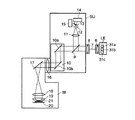
図1は、本発明の第1の実施の形態に係る共焦点顕微鏡共焦点顕微鏡の概略構成を示す図である。図1に示す共焦点顕微鏡は、顕微鏡ユニットM、走査ユニットSU、光源ユニットとしてのレーザユニットLにより構成されている。
(First embodiment)
FIG. 1 is a diagram showing a schematic configuration of a confocal microscope confocal microscope according to the first embodiment of the present invention. The confocal microscope shown in FIG. 1 includes a microscope unit M, a scanning unit SU, and a laser unit L as a light source unit.
レーザユニットLは、近赤外波長以上のレーザ1a、可視域レーザ1b、VIOLETレーザ1c、及びUVレーザ1dなどを備えている。
The laser unit L includes a
近赤外波長以上のレーザ1aからのレーザ光の光路上には、反射ミラー2が配置されている。また、可視域レーザ1bからのレーザ光の光路上には、反射ミラー2で反射されるレーザ光との交点上にダイクロイックミラー3が配置されている。ダイクロイックミラー3は、これら2つのレーザ光路を合成するもので、反射ミラー2で反射されるレーザ光を透過し、可視域レーザ1bからのレーザ光を反射する。
A
VIOLETレーザ1cからのレーザ光の光路上には、ダイクロイックミラー3で合成された光との交点上にダイクロイックミラー4が配置されている。ダイクロイックミラー4は、これら2つのレーザ光路を合成するもので、ダイクロイックミラー3で合成されたレーザ光を透過し、VIOLETレーザ1cからのレーザ光を反射する。
On the optical path of the laser light from the
UVレーザ1dからのレーザ光の光路上には、ダイクロイックミラー4で合成された光との交点上にダイクロイックミラー5が配置されている。ダイクロイックミラー5は、これら2つのレーザ光路を合成するもので、ダイクロイックミラー4で合成されたレーザ光を反射し、UVレーザ1dからのレーザ光を透過し、同一光軸上のマルチ波長のレーザ光を出射する。
A
レーザユニットLのダイクロイックミラー5からのマルチ波長のレーザ光の出射光路には、カップリングレンズ6を介してフォトニック結晶ファイバ(以下、「PCF」と略称する。)7の入射端が配置されている。
An incident end of a photonic crystal fiber (hereinafter abbreviated as “PCF”) 7 is disposed through a
カップリングレンズ6は、ダイクロイックミラー5から出射されたレーザ光をPCF7の入射端へ集光する。PCF7は、多数のエアーホールを規則正しく配列した構造のクラッドを持つ。PCF7の詳細は、後述する。また、PCF7は、マルチ波長のシングルモード光を出力する。
The
PCF7の出射端には、コリメートレンズ8が配置されている。コリメートレンズ8は、マルチ波長のシングルモード光を平行光束に変換する。
A collimating
コリメートレンズ8からの平行光束は、走査ユニットSUに導かれる。
The parallel light flux from the collimating
走査ユニットSUには、コリメートレンズ8からの平行光束の光路上に波長分割素子9が配置されている。波長分割素子9は、平行光束の光のうち、後述する試料21を励起するために必要な励起波長を透過し、試料21で励起されて蛍光を発した蛍光波長を反射する特性を有している。
In the scanning unit SU, a
波長分割素子9を透過したレーザ光(励起波長光)の光路には、ガルバノミラーユニット10が配置されている。ガルバノミラーユニット10は、直交する2方向に光を偏向するための2枚のガルバノミラー10a、10bを有する。これらのガルバノミラー10a、10bによりレーザ光(励起波長光)が2次元方向に偏向される。
A
波長分割素子9の試料21からの蛍光の反射光路には、共焦点観察手段を構成するコンフォーカルレンズ11、共焦点ピンホール12、ダイクロイックミラー13および光電変換素子14,15が配置されている。光電変換素子14,15には、例えばフォトマルチプライアが用いられる。
A
走査ユニットSUには、リレーレンズ16を介して顕微鏡ユニットMが接続されている。
A microscope unit M is connected to the scanning unit SU via a
顕微鏡ユニットMでは、ガルバノミラーユニット10により偏向されたレーザ光(励起波長光)の光路に、ミラー17が配置されている。ミラー17の反射光路には、結像レンズ18および対物レンズ19が配置されている。
In the microscope unit M, a
この場合において、リレーレンズ16を介してミラー17で反射し、さらに結像レンズ18を通ったレーザ光(励起波長光)は、対物レンズ19を透過して、ステージ20に載置された試料21に照射される。このとき、結像レンズ18により対物レンズ19を透過する光は、先のコリメートレンズ8の光束径で試料21上に集光され、ガルバノミラー10a、10bの動きにより試料21上の所定の範囲で走査される。
In this case, the laser light (excitation wavelength light) reflected by the
なお、試料21上に集光されるレーザ光(励起波長光)は、用途に応じて、静止させてスポット的に照射させてもよいし、走査ユニットSUを瞬間的にスキップ作動させて複数の任意の位置にスポット的に照射させるようにしてもよい。
Note that the laser light (excitation wavelength light) condensed on the
試料21は、レーザ光(励起波長光)により、蛍光指示薬が励起され蛍光を発する。この蛍光は、先の光路とは逆方向に、対物レンズ19から結像レンズ18、ミラー17、リレーレンズ16、ガルバノミラー10a、10bを通って波長分割素子9に達し、波長分割素子9で反射してコンフォーカルレンズ11で集光される。そして、この集光位置にあるピンホール12で焦点面だけの蛍光が選択され、ダイクロイックミラー13で蛍光波長を分割した光が光電変換素子14,15により受光され画像化される。
The
なお、近赤外波長以上のレーザ1aとして、IRパルスレーザを用いることができる。このようなIRパルスレーザを用いると、2光子吸収により蛍光画像を取得することができる。このときの2光子吸収現象は、結像位置でのみ発生するので、ピンホール12は、理論的には不要にできる。
An IR pulse laser can be used as the
次に、PCF(フォトニック結晶ファイバ)7について説明する。 Next, the PCF (photonic crystal fiber) 7 will be described.
図2は、PCF7の断面図を示す図である。例えばGeからなるコア7aの周囲にSiからなるクラッド7bが設けられている。また、コア7a周囲のクラッド7bには、多数のエアーホール7cが規則正しく配列されている。この場合、PCF7は、コア7aとクラッド7bともに同じ材質(例えばシリカ)で形成されたものでもよい。
FIG. 2 is a cross-sectional view of the
PCF7は、クラッド7bのエアーホール7cの配列、エアーホール7cの数、クラッド7bの面積全体の中でエアーホール7cが占める割合、コア7aの径およびコア7aの材質などにより特性が決定される。
The characteristics of the
また、PCF7は、
格子間隔Λ:エアーホール7cの中心間隔、
エアーホール径d:クラッド7bのエアーホール径、
コア径2a:中心欠陥の高屈折率部の最小径で第一層エアーホールと外接する円の径、
比エアーホール径d/Λ:dとΛの比(この値は、クラヅドの実効的な屈折率と関係することから、構造の規格化パラメータとしてしばしば使われる)、
空隙率(AIR FILLING FRACTION)F:高屈折率触媒に対するエアーの割合、
規格化周波数Λ/λ:波長に対するエアーホール中心間隔の相対的な大きさ(導波特性の記述にはΛそのものより規格化周波数を用いる。)
とすると、これらの関係式は、

Lattice interval Λ: center interval of
Air hole diameter d: Air hole diameter of the
Core diameter 2a: the diameter of a circle circumscribing the first layer air hole at the minimum diameter of the high refractive index portion of the center defect,
Specific air hole diameter d / Λ: ratio of d and Λ (this value is often used as a structural normalization parameter because it is related to the effective refractive index of the cladding),
Void ratio (AIR FILLING FRACTION) F: Ratio of air to high refractive index catalyst,
Normalized frequency Λ / λ: Relative size of air hole center distance with respect to wavelength (normalized frequency is used from Λ itself for description of waveguide characteristics)
Then, these relational expressions are
ここでの屈折率導波型PCFは、導波原理が全反射である点は、通常のファイバと同じである。両者の特性の違いは、PCF7では、クラッド7bの実効屈折率が光の波長により大きく変化する点である。クラッド7bの実効屈折率は、エアーホール7cの径やピッチと波長との大小関係により変化する。これによって、波長が短くてもシングルモード動作することや、コア7aの面積をどんなに大きくてもシングルモード動作するという特性が生まれる(果てしないシングルモードESM:ENDLESSLY-SINGLEMODE)。
The index-guided PCF here is the same as a normal fiber in that the guiding principle is total reflection. The difference between the two characteristics is that in the
もう1つの違いは、コア7aとの屈折率差を通常の光ファイバよりもはるかに大きくできるという点である。クラッド7bの実効屈折率は、エアーホール7cの直径やピッチによって制御でき、エアーホール7cを大きくすることで空気の影響を高めれば実効屈折率は大きく下がる。すなわち、従来の光ファイバに比べて、屈折率差の変化の自由度が大変大きい。
Another difference is that the refractive index difference from the
コア7aとクラッド7bの屈折率差は、光の導波構造(光の封じ込め構造)に関係し、光の導波構造は、光ファイバの導波路分散と相関を持つ。このことから、PCF7では、導波路分散を広い範囲に亘って変えることが可能である。したがって、この導波路分散と材料分散(ファイバの素材自身が持つ分散)を組み合わせることによって、例えば、短波長でゼロ分散を持つ光ファイバや広い波長帯域に亘って分散がフラットな光ファイバを実現できる。
The refractive index difference between the core 7a and the clad 7b is related to the light waveguide structure (light containment structure), and the light waveguide structure has a correlation with the waveguide dispersion of the optical fiber. From this, in the
さらに、クラッド7bのエアーホール径をXY方向で異ならせる構造異方性を持たせたり、コア径を非円とすることなどで大きな偏波保持性が生まれ、偏波保持ファイバを実現することもできる。 Furthermore, by providing structural anisotropy that varies the air hole diameter of the clad 7b in the XY direction, or by making the core diameter non-circular, a large polarization maintaining property is created, and a polarization maintaining fiber can be realized. it can.
通常の光ファイバの導波モードの数は、次式のV値で与えら、V値が2.4以下の場合にシングルモード動作する。 The number of waveguide modes of a normal optical fiber is given by the V value of the following formula, and single mode operation is performed when the V value is 2.4 or less.
通常のシングルモードファイバでは、nc0とnc1が材料分散により波長とともに同等に変化する。そのため(3)式の√の中の値は、ほとんど波長に対して一定となる。その結果、V値は波長λに反比例して変化することになり、波長が短くなるとシングルモード条件であるV<2.4が成り立たなくなる。 In a normal single mode fiber, n c0 and n c1 change equally with wavelength due to material dispersion. Therefore, the value in √ in equation (3) is almost constant with respect to the wavelength. As a result, the V value changes in inverse proportion to the wavelength λ. When the wavelength is shortened, the single mode condition V <2.4 is not satisfied.
一方、PCF7は、この式が次式で表される。 On the other hand, this formula is expressed by the following formula for PCF7.
Λ:格子間隔、√n0:シリカの屈折率、neff:クラッドの実効屈折率
この(4)式では、√の中のneffの値が波長依存性があるためにVeff値は、通常の光ファイバと異なった波長依存性を示す。これは、波長が短くなるとコアとクラッドの実効屈折率の差が小さくなり、(4)式中のλと√の値が共に小さくなり、それぞれ相殺し合う。つまり、通常の光ファイバのようにλに反比例するのでなく、波長による変化が小さくなり、波長が短くなるにしたがい変化が鈍くなり、一定の値(最大値)に近づく。比エアーホール径d/Λ:dとΛの比が小さい場合、Veff値の最大値は、より小さな値に収束する。Veff値はPCFの場合、4.1以下でシングルモード動作することが示されており、この条件を満たすd/Λ値は、約0.4以下になる。
Λ: Lattice spacing, √n 0 : Refractive index of silica, n eff : Effective refractive index of cladding In this equation (4), the value of n eff in √ is wavelength-dependent, so the Veff value is usually The wavelength dependence is different from that of optical fiber. This is because when the wavelength is shortened, the difference between the effective refractive indexes of the core and the clad becomes small, and both the values of λ and √ in the equation (4) become small and cancel each other. That is, instead of being inversely proportional to λ as in a normal optical fiber, the change due to the wavelength becomes smaller, the change becomes slower as the wavelength becomes shorter, and approaches a certain value (maximum value). Specific air hole diameter d / Λ: When the ratio of d and Λ is small, the maximum value of the Veff value converges to a smaller value. In the case of PCF, the Veff value is 4.1 or less, and it is shown that the single mode operation is performed. The d / Λ value satisfying this condition is about 0.4 or less.
また、NAは、次式で与えられる。 NA is given by the following equation.
通常の光ファイバでは、コアとクラッドの屈折率差△nは、波長によりほとんど変化しないため、NAも波長による変化はほとんどない。これに対し、PCF7では、neffが短波長になるほど、nc0に近づくため、顕著な波長依存性を示し、短波長になるほどNAは小さくなる。 In a normal optical fiber, the refractive index difference Δn between the core and the clad hardly changes depending on the wavelength, and therefore the NA hardly changes depending on the wavelength. In contrast, in PCF7, as n eff becomes shorter, to approach the n c0, showed significant wavelength dependence, NA as the wavelength becomes shorter decreases.
よって、通常の光ファイバでは、短波長でシングルモードにするには、コア径を小さくする必要があるが、PCF7では、短波長でシングルモードにするのに、コア径を小さくしなくても可能である。また、通常の光ファイバでは、NAは、波長による変化がないままであるが、PCF7では、(5)式から明らかなように、短波長になるほどNAを小さくすることが可能である。
Therefore, in the case of a normal optical fiber, it is necessary to reduce the core diameter in order to achieve a single mode at a short wavelength. However, in the case of PCF7, it is possible to make a single mode at a short wavelength without reducing the core diameter. It is. In a normal optical fiber, the NA remains unchanged due to the wavelength. However, in the
このようなPCF7を用いることにより、共焦点顕微鏡として、例えば、405nm近辺のVIOLETレーザ1cと440〜635nmまでの可視域レーザを同時に使用することがあっても、1本のPCF7のみで走査ユニットSU側に光伝搬することができる。勿論、350nm程度の紫外域から1200nmの近赤外波長以上であっても、1本のPCF7のみで対応することが可能である。
By using such a
従って、このようにすれば、レーザユニットLと走査ユニットSUとの間を接続するファイバとしてPCF7を用いることで、近赤外波長域からUV波長域までの広い波長域の光を1本のPCF7のみで走査ユニットSU側に光伝搬することができる。つまり、従来では、波長域が広がると、所定の波長域毎にファイバを分けて、走査ユニットに光伝搬させる必要があったが、これを最小1本のPCF7のみで光伝搬することができる。
Therefore, in this way, by using the
このことは、レーザユニットLを各波長域毎に、それぞれ用意する必要がなく、1つに纏めることができるので、レーザ光をコントロールするための制御系も構成が簡単になるばかりか、配線数を減らすことも可能であり、価格的に安価にできるとともに、配線数を減らせることで、信頼性の向上も図れる。 This means that it is not necessary to prepare each laser unit L for each wavelength region, and the laser units L can be combined into one. Therefore, the configuration of the control system for controlling the laser light is simplified, and the number of wires is also reduced. It is also possible to reduce the number of wires, and the cost can be reduced, and the number of wirings can be reduced to improve the reliability.
また、1本のPCF7で走査ユニットSU側に光伝搬できることで、走査ユニットに光を導入した後も、所定の波長域毎にコリメートレンズなどの光学系を用意する必要がなくなり、波長域毎の光軸調整を必要としない。従来、各波長域毎の光学系の光軸調整は、物理的に行われるため、熱膨張などによって、光軸ずれ発生し易かったが、1本のPCF7のみで同軸上に光を導入し、光軸調整を省略できるので、光軸のずれがなくなり、光軸ずれによる試料上の走査位置が変わることがないため、取得される画像の信頼性が高い。
Further, since light can be propagated to the scanning unit SU side by one
さらに、顕微鏡を納入後、新たに他の波長領域のレーザを追加した場合も、レーザユニットLで光学調整をすればよく、PCF7については、そのまま対応できるので、ユーザ先でのセットアップも容易である。また、ファイバが何らかの影響で壊れた場合も、従来であれば、ファイバのカップリング調整と走査ユニットに導入するための光学調整の他に、さらに走査ユニット内での光学調整も必要であるが、PCF7であれば、交換の後、PCF7のカップリング調整と走査ユニットに導入するための光学調整だけで済むためメンテナンス性が高い。
Furthermore, even when a laser of another wavelength region is newly added after delivery of the microscope, it is only necessary to perform optical adjustment with the laser unit L, and the
さらにまた、従来では、走査ユニット内で各波長領域毎のコリメートレンズより出射したレーザ光を対物レンズに導入するため、これらのレーザ光をダイクロイックミラーなどを用いた光線方向変換エレメントで合成するようにしていたが、これら光線方向変換エレメントを必要としないので、走査ユニットをコンパクトにすることができるとともに、光線方向変換エレメントでの光の損失も防止でき、効率のよい光伝搬を行なうことができる。 Furthermore, conventionally, in order to introduce the laser light emitted from the collimating lens for each wavelength region in the scanning unit into the objective lens, the laser light is synthesized by a light beam direction conversion element using a dichroic mirror or the like. However, since these light direction changing elements are not required, the scanning unit can be made compact, and loss of light in the light direction changing elements can be prevented, and efficient light propagation can be performed.
図3は、PCF7の端面処理について説明する図である。図3において、PCF7は、Geからなるコア7aの周囲に、シリカからなるクラッド7bが設けられ、さらに、コア7a周囲のクラッド7bに、多数のエアーホール7cが配置されている。この場合において、カップリングレンズ6やコリメートレンズ8との光学的な接続をするために、PCF7の両端にコネクタ(図示しない)が取り付けられる。コネクタを取り付ける際に、PCF7の両端を研磨する必要がある。しかし、PCF7は屈折率差を持たせるために微小な穴(エアーホール7c)が開いており、端面処理のためクラッド7b端面を研磨すると、エアーホール7cが埋まってしまい本来の性能を出せなくなってしまう。そこで、予めクラッド7b端面において、10〜500μm程度の範囲だけエアーホール7c部分を無くし、この部分で端面研磨できるようにする。この場合、カップリングレンズ6を介して入射されるレーザ光は、コア7a上の、該コア7a先端からエアーホール7c先端までの間のエアーホール7cが存在しない部分で焦点を結ばせるようにすればよいが、望ましくは、コア7a上のエアーホール7c先端に相当する位置がよい。
FIG. 3 is a diagram for explaining the end face processing of the
第1の実施の形態では、レーザユニットLとして、近赤外波長以上のレーザ1a、可視域レーザ1b、VIOLETレーザ1c、UVレーザ1dなどが設けられる例を述べたが、レーザが2個以上存在すれば、上述したと同様な効果を得られる。
In the first embodiment, the laser unit L is provided with the
(第2の実施の形態)
次に、本発明の第2の実施の形態を説明する。
(Second Embodiment)
Next, a second embodiment of the present invention will be described.
図4は、本発明の第2の実施の形態の概略構成を示す図であり、図1と同一部分には、同符号を付している。 FIG. 4 is a diagram showing a schematic configuration of the second embodiment of the present invention, and the same parts as those in FIG.
図4において、共焦点顕微鏡は、顕微鏡ユニットM、走査ユニットSUの他、光源ユニットとしてLED光源ユニットLEを備えている。 In FIG. 4, the confocal microscope includes an LED light source unit LE as a light source unit in addition to the microscope unit M and the scanning unit SU.
LED光源ユニットLEには、発光ダイオードとして、それぞれ発光色の異なる青色のLED31a、緑色のLED31b、赤色のLED31cが設けられている。
The LED light source unit LE is provided with a
LED31a、31b、31cから発せられる光は、図示しない合成手段で合成され、マルチ波長の光として、カップリングレンズ6を介してPCF7の入射端へ集光する。PCF7は、マルチ波長のシングルモード光の光を出力する。
Lights emitted from the
以下、第1の実施の形態で述べたと同様で、コリメートレンズ8で平行光束になって、波長分割素子9で、平行光束の光の内、試料21を励起するために必要な励起波長が透過する。
Hereinafter, in the same manner as described in the first embodiment, the
波長分割素子9で励起波長光となった光は、ガルバノミラーユニット10で、試料21面上のXY方向に偏向され、リレーレンズ16を透過してミラー17に入射する。ミラー17で反射した光は、結像レンズ18より対物レンズ19を透過して試料21上に集光され、ガルバノミラー10a、10bの動きにより試料21上の所定の範囲で走査される。
The light that has become the excitation wavelength light by the
第1の実施の形態と同様に、試料21上に集光されるレーザ光(励起波長光)は、用途に応じて、静止させてスポット的に照射させてもよいし、走査ユニットSUを瞬間的にスキップ作動させて複数の任意の位置にスポット的に照射させるようにしてもよい。
As in the first embodiment, the laser light (excitation wavelength light) focused on the
試料21上に照射されるレーザ光(励起波長光)により、蛍光指示薬が励起されると、蛍光が発する。この蛍光は、先の光路とは逆方向に、対物レンズ19から結像レンズ18、ミラー17、リレーレンズ16、ガルバノミラー10a、10bを通って波長分割素子9で反射してコンフォーカルレンズ11で集光される。そして、この集光位置にあるピンホール12で焦点面だけの蛍光が選択され、ダイクロイックミラー13で蛍光波長を分割した光が光電変換素子14,15により受光され画像化される。
When the fluorescent indicator is excited by laser light (excitation wavelength light) irradiated on the
このようにすれば、光源ユニットとして、発光色の異なるLED31a、31b、31cを有するLED光源ユニットLEを用い、走査ユニットSUとの間をPCF7で接続するようにしたので、レーザを使わないポイントスキャン方式の走査型共焦点顕微鏡を実現できる。
In this case, the LED light source unit
LED光源ユニットLEからのLED光をPCF7に導入するが、PCF7は、従来のシングルモードファイバに比べてコア径を大きくすることが可能(例えば数十μm程度)なので、カップリング効率をよくすることができ、共焦点顕微鏡で必要なシングルモードの光を確実に得ることができる。
LED light from the LED light source unit LE is introduced into the
LED光源ユニットLEのLED31a、31b、31cを光源として使用して共焦点顕微鏡を構成できるので、価格的にも安価にできる。また、LED31a、31b、31cは、レーザに比べて消費電力が小さく、省エネルギー化が可能である。さらに、LED31a、31b、31cは、非常に小さいため、コンパクトな光源を実現できる。このため、図4では、LED光源ユニットLEは、走査ユニットSUと分けて構成されていたが、走査ユニットSU内に組み込むことも可能になり、一体化によるさらなるコンパクト化が実現できる。
Since the confocal microscope can be configured by using the
LED光源ユニットLEのLED31a、31b、31cは、電圧のオンオフのみで点灯、消灯が可能であり、また、輝度を変化させるために、電流を可変したり、パルス状にON/OFFすることなどの変調により、輝度を変えることも可能で、これによって調光も簡単にできる。このことは、従来においては、調光制御するために特別の機構が必要であったが、電気制御回路だけで実現できるので、コンパクトになるとともに、安価にできる。
The
LED31a、31b、31cは、レーザに比べて、寿命が長く、システムの維持コストが安いという効果もある。
The
LEDは、レーザに比べて、いろいろな波長のものも実用化されており、試料21の励起波長に対して、波長選択自由度が高いというメリットもある。
LEDs having various wavelengths as compared with lasers have been put into practical use, and there is an advantage that the degree of freedom in wavelength selection is high with respect to the excitation wavelength of the
LEDは、レーザと比べると波長幅が広い。よって、BAフィルタやAOTFなどの波長選択素子と組み合わせて、必要な波長幅に変換して使用することで、波長の選択性を向上させることができる。 An LED has a wider wavelength width than a laser. Therefore, wavelength selectivity can be improved by combining with a wavelength selection element such as a BA filter or AOTF and converting it to a required wavelength width.
一方、図4では、LED光源ユニットLEには、LED31a、31b、31cのみを設けたが、レーザ光源を組み合わせることで、強い光が必要な場合は、レーザを利用し、弱い光でも構わない場合は、LEDを利用するという利便性の向上も可能である。
On the other hand, in FIG. 4, the LED light source unit LE is provided with only the
(第3の実施の形態)
次に、本発明の第3の実施の形態を説明する。
(Third embodiment)
Next, a third embodiment of the present invention will be described.
従来のファイバを用いる場合は、カップリングレンズおよびコリメートレンズの波長補正を行わない。これは、これまでのファイバでは、NAが波長依存性をほとんど持たないからである。 When a conventional fiber is used, wavelength correction of the coupling lens and the collimating lens is not performed. This is because NA has almost no wavelength dependence in the conventional fiber.
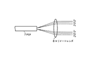
しかし、第1の実施の形態に用いられるPCF7は、NAが波長依存性を持っている。このためカップリングレンズ6とコリメートレンズ8は、波長依存性を考慮した設計が必要である。つまり、これらカップリングレンズ6とコリメートレンズ8は、PCF7のコア7aに対してカップリング作用又はコリメート作用が波長依存しないものにする必要がある。このため、短波長域についてNAが小さく、長波長域についてはNAが大きくなるように特性を補正するレンズ構成とする必要がある。ちなみに、コリメートレンズ8は、図5に示すように、PCF7のNAがほぼ一定の場合、異なる波長λ1、λ2、λ3によって光の広がりが異なる。ここでの波長は、λ1<λ2<λ3である。
However, in the
そこで、第3の実施の形態では、カップリングレンズ6およびコリメートレンズ8として、波長によってNAが変化するようなレンズ(例えば、所定量の色収差を持たせたレンズ)を用いる。このようにすれば、カップリングレンズ6によるカップリング効率とコリメートレンズ8によるコリメート光の平行度を最適化することが可能になる。つまり、カップリングレンズ6については、カップリング効率を改善できるので、PCF7へ入射する光の損失を少なくすることが可能となり、光の強度が強い光源を使う必要がなく省エネルギー化が図ることができる。また、コリメートレンズについても、光の平行度を保ったまま、光束径をほぼ一定にすることができるので、対物レンズ19に入射する光の損失を最小限にして試料21に導くことができ、励起効率を良くすることが可能である。
Therefore, in the third embodiment, as the
(第3の実施の形態の変形例)
また、対物レンズ19で形成されるビームスポット径は、光の波長λと開口数NAに依存する。波長λが短いほど、ビームスポット径は小さくなる。そこで、光の波長λによるスポット径の変動を開口数NA(すなわち、対物レンズへの入射ビーム径)の調節によって相殺するように、PCF7以降のコリメートレンズ8を含む光学系の波長特性を光学的にコンペンセート(補償)する。これによって、対物レンズ19からの光のスポット径は、波長λに関わらず等しく揃えることができる。従って、分解能に対する波長の影響をなくすことができる。
(Modification of the third embodiment)
The beam spot diameter formed by the
(第4の実施の形態)
次に、本発明の第4の実施の形態を説明する。
(Fourth embodiment)
Next, a fourth embodiment of the present invention will be described.
ところで、PCF7は、規則正しいエアーホールが開いているが、これでは、共焦点顕微鏡で必要とする偏波特性を持たせた光伝播が得られないことがある。
By the way, although the regular air holes are opened in the
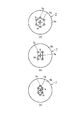
そこで、第4の実施の形態のPCF7には、図6(a)及び図6(b)に示すようにコア7a周囲のクラッド7bに形成されるエアーホール7cの配置を鉛直V方向と水平H方向で異ならしたものが用いられる。
Therefore, in the
このようなPCF7によれば、偏波特性を持った波長の光を、偏波特性を維持したままシングルモード伝播することが可能となる。
According to such a
なお、エアーホール7cの鉛直V方向と水平H方向の配置は、例えば、図7(a)に示すように六角形状、図7(b)に示す長方形状、図7(c)に示す楕円状など各種のものが考えられる。 The arrangement of the air holes 7c in the vertical V direction and the horizontal H direction is, for example, hexagonal as shown in FIG. 7 (a), rectangular as shown in FIG. 7 (b), and elliptical as shown in FIG. 7 (c). Various things are possible.
従って、このようにすれば、PCF7により偏波特性を維持した波長の光伝播が可能になるので、共焦点顕微鏡では、DIC観察が、簡単に可能である。仮に、PCF7で偏波特性を維持できなければ、別途波長板などが必要となるが、PCF7で偏波特性を維持した光伝播を可能とすることで、波長板が不要になる。このことは、波長板での光の損失を無くすことができるので、さらに明るく効率の良いシステムの構築が可能である。
Accordingly, if this is done, light propagation with a wavelength that maintains the polarization characteristics by the
なお、本発明は、上記実施の形態に限定されるものでなく、実施段階では、その要旨を変更しない範囲で種々変形することが可能である。 In addition, this invention is not limited to the said embodiment, In the implementation stage, it can change variously in the range which does not change the summary.
さらに、上記実施の形態には、種々の段階の発明が含まれており、開示されている複数の構成要件における適宜な組み合わせにより種々の発明が抽出できる。例えば、実施の形態に示されている全構成要件から幾つかの構成要件が削除されても、発明が解決しようとする課題の欄で述べた課題を解決でき、発明の効果の欄で述べられている効果が得られる場合には、この構成要件が削除された構成が発明として抽出できる。 Furthermore, the above embodiments include inventions at various stages, and various inventions can be extracted by appropriately combining a plurality of disclosed constituent elements. For example, even if some constituent requirements are deleted from all the constituent requirements shown in the embodiment, the problem described in the column of the problem to be solved by the invention can be solved, and is described in the column of the effect of the invention. If the above effect is obtained, a configuration from which this configuration requirement is deleted can be extracted as an invention.
なお、以上述べた実施の形態には、以下の発明も含まれる。 The embodiments described above include the following inventions.
(1) 前記フォトニック結晶ファイバは、入射端側にカップリングレンズ、出射端側にコリメートレンズがそれぞれ配置されること。 (1) In the photonic crystal fiber, a coupling lens is disposed on the incident end side, and a collimating lens is disposed on the exit end side.
(2) 前記フォトニック結晶ファイバは、少なくとも2つの光源に対して1本設けられること。 (2) One photonic crystal fiber is provided for at least two light sources.
本発明の実施の形態によれば、例えば、近赤外波長域からUV波長域までの広い波長域の光を1本のPCFのみで光走査手段側にシングルモードで光伝搬することができるので、光走査手段側に光を導入した後も、波長域毎に光学系を用意する必要がなくなり、波長域毎の光軸調整を必要としない。これにより、光軸のずれがなくなり、光軸ずれによる試料上の走査位置が変わることがない。さらに、顕微鏡を納入後、新たに他の波長領域のレーザを追加した場合も、光源ユニットで光学調整をすればよく、PCFについては、PCF自身の交換や増設を必要とせずに、そのまま対応できるので、ユーザ先でのセットアップも容易である。なお、上記の実施の形態では、PCFで近赤外波長域からUV波長域までの波長域の光を光走査手段側にシングルモードで光伝搬する例を説明したが、赤外波長域からUV波長域までの波長域の光を光伝搬しても良い。 According to the embodiment of the present invention, for example, light in a wide wavelength range from the near-infrared wavelength range to the UV wavelength range can be propagated in a single mode to the optical scanning means side with only one PCF. Even after the light is introduced into the optical scanning means side, it is not necessary to prepare an optical system for each wavelength region, and optical axis adjustment for each wavelength region is not required. Thereby, the optical axis is not displaced, and the scanning position on the sample is not changed by the optical axis displacement. Furthermore, even when a laser of another wavelength region is newly added after delivery of the microscope, it is only necessary to perform optical adjustment with the light source unit, and the PCF can be handled as it is without requiring replacement or expansion of the PCF itself. Therefore, setup at the user site is easy. In the above embodiment, an example in which light in the wavelength range from the near infrared wavelength range to the UV wavelength range is propagated in the single mode to the optical scanning unit side by the PCF has been described. Light in the wavelength range up to the wavelength range may be propagated.
また、本発明の実施の形態によれば、コア径を太くした(例えば数十μm程度)PCFを用いることで発光ダイオードのように比較的大きな点光源を使用できる。また、光源ユニットとして、発光色の異なる発光ダイオードを用いることで、ポイントスキャン方式の共焦点顕微鏡を実現できる。 Further, according to the embodiment of the present invention, a relatively large point light source such as a light emitting diode can be used by using a PCF having a large core diameter (for example, about several tens of μm). In addition, a point-scan confocal microscope can be realized by using light emitting diodes having different emission colors as the light source unit.
さらに、本発明の実施の形態によれば、対物レンズからの光のスポット径を揃えることができ、波長分解能の影響をなくすことができる。 Furthermore, according to the embodiment of the present invention, the spot diameter of light from the objective lens can be made uniform, and the influence of wavelength resolution can be eliminated.
さらに、本発明の実施の形態によれば、PCFにより偏波特性を維持した波長の光伝播が可能になる。 Furthermore, according to the embodiment of the present invention, it is possible to propagate light having a wavelength with polarization characteristics maintained by the PCF.
M…顕微鏡ユニット
SU…走査ユニット
L…レーザユニット
1a…近赤外波長以上のレーザ、1b…可視域レーザ、1c…VIOLETレーザ、1d…UVレーザ
2…反射ミラー、3、4、5…ダイクロイックミラー
6…カップリングレンズ、7…PCF
7a…コア、7b…クラッド、7c…エアーホール
8…コリメートレンズ、9…波長分割素子
10…ガルバノミラーユニット、10a.10b…ガルバノミラー
11…コンフォーカルレンズ、12…共焦点ピンホール
13…ダイクロイックミラー、14.15…光電変換素子
16…リレーレンズ、17…ミラー、18…結像レンズ
19…対物レンズ、20…ステージ、21…試料
31a.31b、31d…LED
M ... Microscope unit SU ... Scanning unit L ...
7a ... core, 7b ... clad, 7c ...
Claims (8)
前記光源ユニットからの光を試料上に集光させる対物レンズと、
前記光源ユニットからの光を前記試料上で2次元走査する光走査手段と、
前記光源ユニットと前記光走査手段との間に配置され、前記光源ユニットから導入される光を前記走査手段側に伝搬する一つのフォトニック結晶ファイバと、
前記フォトニック結晶ファイバから出射した光をコリメートして前記光走査手段へ導くコリメート手段と、
前記光走査手段による2次元走査により前記試料上から発生する蛍光を共焦点観察する蛍光観察手段と、
前記光源ユニットからの光を用いてDIC観察を行うDIC観察手段とを具備し、
前記光源ユニットにより発生する光は、波長405nm付近の光と波長635nm付近の光を含み、かつ偏光特性を有する光であり、
前記フォトニック結晶ファイバは、コアの周囲に設けられるクラッドに配置された複数のエアーホールを有するとともに、このエアーホールの配置が鉛直方向と水平方向で異なることにより偏波特性を維持した光伝播を可能にしたことを特徴とする共焦点顕微鏡。 A light source unit having at least two light sources that generate light of different wavelengths;
An objective lens for condensing the light from the light source unit on the sample;
Light scanning means for two-dimensionally scanning light from the light source unit on the sample;
One photonic crystal fiber disposed between the light source unit and the light scanning means and propagating light introduced from the light source unit to the scanning means side ;
Collimating means for collimating the light emitted from the photonic crystal fiber and guiding it to the optical scanning means;
Fluorescence observation means for confocal observation of fluorescence generated from the sample by two-dimensional scanning by the light scanning means;
DIC observation means for performing DIC observation using light from the light source unit ,
The light generated by the light source unit includes light having a wavelength of about 405 nm and light having a wavelength of about 635 nm, and has polarization characteristics.
The photonic crystal fiber has a plurality of air holes arranged in a clad provided around the core, and the light propagation maintaining polarization characteristics by the arrangement of the air holes being different in the vertical direction and the horizontal direction. A confocal microscope characterized by that.
前記光源ユニットは可視域の光と、バイオレット、紫外域、近赤外または赤外の少なくとも1つの帯域の光とを発生し、
前記フォトニクス結晶ファイバは、前記光源ユニットが発生した光を1本のフォトニクス結晶ファイバのみで前記光走査ユニットに伝送することを特徴とする共焦点顕微鏡。 The confocal microscope according to claim 1 ,
The light source unit generates light in the visible range and light in at least one band of violet, ultraviolet, near infrared, or infrared,
The confocal microscope, wherein the photonic crystal fiber transmits light generated by the light source unit to the optical scanning unit using only one photonic crystal fiber.
前記コリメートレンズを所定量の色収差をもたせたレンズ構成とすることにより、波長によらずコリメートされた光の平行度を保ったまま光束径をほぼ一定にすることを特徴とする共焦点顕微鏡。 In confocal microscope according to claim 1 or 2, wherein the collimating means comprises a collimating lens,
A confocal microscope characterized in that the collimating lens has a lens configuration having a predetermined amount of chromatic aberration, so that the diameter of the light beam is substantially constant while maintaining the parallelism of the collimated light regardless of the wavelength .
Priority Applications (1)
| Application Number | Priority Date | Filing Date | Title |
|---|---|---|---|
| JP2004217423A JP4677208B2 (en) | 2003-07-29 | 2004-07-26 | Confocal microscope |
Applications Claiming Priority (2)
| Application Number | Priority Date | Filing Date | Title |
|---|---|---|---|
| JP2003203132 | 2003-07-29 | ||
| JP2004217423A JP4677208B2 (en) | 2003-07-29 | 2004-07-26 | Confocal microscope |
Publications (3)
| Publication Number | Publication Date |
|---|---|
| JP2005062850A JP2005062850A (en) | 2005-03-10 |
| JP2005062850A5 JP2005062850A5 (en) | 2007-08-30 |
| JP4677208B2 true JP4677208B2 (en) | 2011-04-27 |
Family
ID=34379866
Family Applications (1)
| Application Number | Title | Priority Date | Filing Date |
|---|---|---|---|
| JP2004217423A Active JP4677208B2 (en) | 2003-07-29 | 2004-07-26 | Confocal microscope |
Country Status (1)
| Country | Link |
|---|---|
| JP (1) | JP4677208B2 (en) |
Families Citing this family (54)
| Publication number | Priority date | Publication date | Assignee | Title |
|---|---|---|---|---|
| JP4241038B2 (en) | 2000-10-30 | 2009-03-18 | ザ ジェネラル ホスピタル コーポレーション | Optical method and system for tissue analysis |
| WO2004088361A2 (en) | 2003-03-31 | 2004-10-14 | The General Hospital Corporation | Speckle reduction in optical coherence tomography by path length encoded angular compounding |
| KR101386971B1 (en) | 2003-06-06 | 2014-04-18 | 더 제너럴 하스피탈 코포레이션 | Process and apparatus for a wavelength tunning source |
| WO2006014392A1 (en) | 2004-07-02 | 2006-02-09 | The General Hospital Corporation | Endoscopic imaging probe comprising dual clad fibre |
| WO2006024014A2 (en) | 2004-08-24 | 2006-03-02 | The General Hospital Corporation | Process, system and software arrangement for measuring a mechanical strain and elastic properties of a sample |
| US8208995B2 (en) | 2004-08-24 | 2012-06-26 | The General Hospital Corporation | Method and apparatus for imaging of vessel segments |
| JP2008521516A (en) | 2004-11-29 | 2008-06-26 | ザ ジェネラル ホスピタル コーポレイション | Configuration, apparatus, endoscope, catheter, and method for performing optical image generation by simultaneously illuminating and detecting multiple points on a sample |
| JP5065008B2 (en) * | 2005-03-18 | 2012-10-31 | 古河電気工業株式会社 | Optical fiber and waveguide |
| US7756375B2 (en) * | 2005-03-18 | 2010-07-13 | The Furukawa Electric Co., Ltd. | Optical fiber and waveguide |
| EP2325803A1 (en) | 2005-04-28 | 2011-05-25 | The General Hospital Corporation | Evaluating optical coherence tomography information for an anatomical structure |
| US9060689B2 (en) | 2005-06-01 | 2015-06-23 | The General Hospital Corporation | Apparatus, method and system for performing phase-resolved optical frequency domain imaging |
| ES2354287T3 (en) | 2005-08-09 | 2011-03-11 | The General Hospital Corporation | APPARATUS AND METHOD FOR PERFORMING A DEMODULATION IN QUADRATURE BY POLARIZATION IN OPTICAL COHERENCE TOMOGRAPHY. |
| CN101365375B (en) | 2005-09-29 | 2013-09-11 | 通用医疗公司 | Method and apparatus for optical imaging via spectral encoding |
| US7889348B2 (en) * | 2005-10-14 | 2011-02-15 | The General Hospital Corporation | Arrangements and methods for facilitating photoluminescence imaging |
| US8145018B2 (en) | 2006-01-19 | 2012-03-27 | The General Hospital Corporation | Apparatus for obtaining information for a structure using spectrally-encoded endoscopy techniques and methods for producing one or more optical arrangements |
| PL1973466T3 (en) | 2006-01-19 | 2021-07-05 | The General Hospital Corporation | Ballon imaging catheter |
| WO2007149603A2 (en) | 2006-02-01 | 2007-12-27 | The General Hospital Corporation | Apparatus for applying a plurality of electro-magnetic radiations to a sample |
| JP5524487B2 (en) | 2006-02-01 | 2014-06-18 | ザ ジェネラル ホスピタル コーポレイション | A method and system for emitting electromagnetic radiation to at least a portion of a sample using a conformal laser treatment procedure. |
| EP1987318B1 (en) | 2006-02-24 | 2015-08-12 | The General Hospital Corporation | Methods and systems for performing angle-resolved fourier-domain optical coherence tomography |
| EP2517616A3 (en) | 2006-05-10 | 2013-03-06 | The General Hospital Corporation | Processes, arrangements and systems for providing frequency domain imaging of a sample |
| WO2008049118A2 (en) | 2006-10-19 | 2008-04-24 | The General Hospital Corporation | Apparatus and method for obtaining and providing imaging information associated with at least one portion of a sample and effecting such portion(s) |
| JP2008139820A (en) * | 2006-11-02 | 2008-06-19 | Olympus Corp | Microscope illumination apparatus |
| EP2602651A3 (en) | 2007-03-23 | 2014-08-27 | The General Hospital Corporation | Methods, arrangements and apparatus for utilizing a wavelength-swept laser using angular scanning and dispersion procedures |
| US10534129B2 (en) | 2007-03-30 | 2020-01-14 | The General Hospital Corporation | System and method providing intracoronary laser speckle imaging for the detection of vulnerable plaque |
| WO2010009136A2 (en) | 2008-07-14 | 2010-01-21 | The General Hospital Corporation | Apparatus and methods for color endoscopy |
| JP5731394B2 (en) | 2008-12-10 | 2015-06-10 | ザ ジェネラル ホスピタル コーポレイション | System, apparatus and method for extending imaging depth range of optical coherence tomography through optical subsampling |
| US9615748B2 (en) | 2009-01-20 | 2017-04-11 | The General Hospital Corporation | Endoscopic biopsy apparatus, system and method |
| CN102308444B (en) | 2009-02-04 | 2014-06-18 | 通用医疗公司 | Apparatus and method for utilization of a high-speed optical wavelength tuning source |
| BR112012001042A2 (en) | 2009-07-14 | 2016-11-22 | Gen Hospital Corp | fluid flow measurement equipment and method within anatomical structure. |
| ES2831223T3 (en) | 2010-03-05 | 2021-06-07 | Massachusetts Gen Hospital | Apparatus for providing electromagnetic radiation to a sample |
| JP2011215285A (en) * | 2010-03-31 | 2011-10-27 | Yamatake Corp | Light-receiving optical system |
| US9069130B2 (en) | 2010-05-03 | 2015-06-30 | The General Hospital Corporation | Apparatus, method and system for generating optical radiation from biological gain media |
| US9795301B2 (en) | 2010-05-25 | 2017-10-24 | The General Hospital Corporation | Apparatus, systems, methods and computer-accessible medium for spectral analysis of optical coherence tomography images |
| US9557154B2 (en) | 2010-05-25 | 2017-01-31 | The General Hospital Corporation | Systems, devices, methods, apparatus and computer-accessible media for providing optical imaging of structures and compositions |
| EP2575591A4 (en) | 2010-06-03 | 2017-09-13 | The General Hospital Corporation | Apparatus and method for devices for imaging structures in or at one or more luminal organs |
| US9510758B2 (en) | 2010-10-27 | 2016-12-06 | The General Hospital Corporation | Apparatus, systems and methods for measuring blood pressure within at least one vessel |
| WO2012172718A1 (en) | 2011-06-16 | 2012-12-20 | 富士電機株式会社 | Light-guide apparatus and light-guiding method |
| WO2013013049A1 (en) | 2011-07-19 | 2013-01-24 | The General Hospital Corporation | Systems, methods, apparatus and computer-accessible-medium for providing polarization-mode dispersion compensation in optical coherence tomography |
| EP2769491A4 (en) | 2011-10-18 | 2015-07-22 | Gen Hospital Corp | Apparatus and methods for producing and/or providing recirculating optical delay(s) |
| WO2013148306A1 (en) | 2012-03-30 | 2013-10-03 | The General Hospital Corporation | Imaging system, method and distal attachment for multidirectional field of view endoscopy |
| WO2013177154A1 (en) | 2012-05-21 | 2013-11-28 | The General Hospital Corporation | Apparatus, device and method for capsule microscopy |
| JP6227652B2 (en) | 2012-08-22 | 2017-11-08 | ザ ジェネラル ホスピタル コーポレイション | System, method, and computer-accessible medium for fabricating a miniature endoscope using soft lithography |
| JP6560126B2 (en) | 2013-01-28 | 2019-08-14 | ザ ジェネラル ホスピタル コーポレイション | Apparatus and method for providing diffusion spectroscopy superimposed on optical frequency domain imaging |
| WO2014120791A1 (en) | 2013-01-29 | 2014-08-07 | The General Hospital Corporation | Apparatus, systems and methods for providing information regarding the aortic valve |
| US11179028B2 (en) | 2013-02-01 | 2021-11-23 | The General Hospital Corporation | Objective lens arrangement for confocal endomicroscopy |
| JP6378311B2 (en) | 2013-03-15 | 2018-08-22 | ザ ジェネラル ホスピタル コーポレイション | Methods and systems for characterizing objects |
| WO2014186353A1 (en) | 2013-05-13 | 2014-11-20 | The General Hospital Corporation | Detecting self-interefering fluorescence phase and amplitude |
| EP3021735A4 (en) | 2013-07-19 | 2017-04-19 | The General Hospital Corporation | Determining eye motion by imaging retina. with feedback |
| WO2015009932A1 (en) | 2013-07-19 | 2015-01-22 | The General Hospital Corporation | Imaging apparatus and method which utilizes multidirectional field of view endoscopy |
| EP3025173B1 (en) | 2013-07-26 | 2021-07-07 | The General Hospital Corporation | Apparatus with a laser arrangement utilizing optical dispersion for applications in fourier-domain optical coherence tomography |
| US9733460B2 (en) | 2014-01-08 | 2017-08-15 | The General Hospital Corporation | Method and apparatus for microscopic imaging |
| WO2015116986A2 (en) | 2014-01-31 | 2015-08-06 | The General Hospital Corporation | System and method for facilitating manual and/or automatic volumetric imaging with real-time tension or force feedback using a tethered imaging device |
| WO2015153982A1 (en) | 2014-04-04 | 2015-10-08 | The General Hospital Corporation | Apparatus and method for controlling propagation and/or transmission of electromagnetic radiation in flexible waveguide(s) |
| WO2016015052A1 (en) | 2014-07-25 | 2016-01-28 | The General Hospital Corporation | Apparatus, devices and methods for in vivo imaging and diagnosis |
Citations (6)
| Publication number | Priority date | Publication date | Assignee | Title |
|---|---|---|---|---|
| JP2002048979A (en) * | 2000-06-17 | 2002-02-15 | Leica Microsystems Heidelberg Gmbh | Instrument for examining microscopic preparation with scanning microscope |
| JP2002267933A (en) * | 2001-03-13 | 2002-09-18 | Olympus Optical Co Ltd | Laser microscope |
| JP2002323625A (en) * | 2001-04-25 | 2002-11-08 | Sumitomo Electric Ind Ltd | End face structure of optical fiber and optical fiber |
| JP2003021784A (en) * | 2001-07-06 | 2003-01-24 | Olympus Optical Co Ltd | Scanning laser microscope and image acquiring method for the same |
| JP2003107266A (en) * | 2001-09-27 | 2003-04-09 | Nippon Telegr & Teleph Corp <Ntt> | Polarization maintaining optical fiber and optical fiber for absolute single polarization |
| JP2003128429A (en) * | 2001-10-17 | 2003-05-08 | Mitsubishi Cable Ind Ltd | Optical element and method of manufacturing it, optical fiber and method of manufacturing it |
-
2004
- 2004-07-26 JP JP2004217423A patent/JP4677208B2/en active Active
Patent Citations (6)
| Publication number | Priority date | Publication date | Assignee | Title |
|---|---|---|---|---|
| JP2002048979A (en) * | 2000-06-17 | 2002-02-15 | Leica Microsystems Heidelberg Gmbh | Instrument for examining microscopic preparation with scanning microscope |
| JP2002267933A (en) * | 2001-03-13 | 2002-09-18 | Olympus Optical Co Ltd | Laser microscope |
| JP2002323625A (en) * | 2001-04-25 | 2002-11-08 | Sumitomo Electric Ind Ltd | End face structure of optical fiber and optical fiber |
| JP2003021784A (en) * | 2001-07-06 | 2003-01-24 | Olympus Optical Co Ltd | Scanning laser microscope and image acquiring method for the same |
| JP2003107266A (en) * | 2001-09-27 | 2003-04-09 | Nippon Telegr & Teleph Corp <Ntt> | Polarization maintaining optical fiber and optical fiber for absolute single polarization |
| JP2003128429A (en) * | 2001-10-17 | 2003-05-08 | Mitsubishi Cable Ind Ltd | Optical element and method of manufacturing it, optical fiber and method of manufacturing it |
Also Published As
| Publication number | Publication date |
|---|---|
| JP2005062850A (en) | 2005-03-10 |
Similar Documents
| Publication | Publication Date | Title |
|---|---|---|
| JP4677208B2 (en) | Confocal microscope | |
| JP6804636B2 (en) | Optical imaging system using vortex fibers for multimode lighting | |
| US7953308B2 (en) | System and method for fiber optic bundle-based illumination for imaging system | |
| JP5254205B2 (en) | Optical scanning device and two-dimensional image display device using the same | |
| US7239384B2 (en) | Laser-scanning fluoroscopy apparatus | |
| JP6282658B2 (en) | Confocal microscope with freely adjustable sample scanning | |
| EP1601070A2 (en) | Wavelength stabilized laser | |
| US7215468B2 (en) | Confocal microscope | |
| US20080212191A1 (en) | Optical arrangement and optical method | |
| KR102409738B1 (en) | Super-resolution imaging | |
| US8982918B2 (en) | System, device and method for stabilizing the optical output power of an optical system | |
| Mashayekh et al. | Silicon nitride PIC-based multi-color laser engines for life science applications | |
| Li et al. | Single-layer multitasking vortex-metalens for ultra-compact two-photon excitation STED endomicroscopy imaging | |
| JP2002048979A (en) | Instrument for examining microscopic preparation with scanning microscope | |
| CN105683801A (en) | Microscope with an element for changing the shape of the illuminating light focus point | |
| WO2020095417A1 (en) | Optical multiplexer, light source module, two-dimensional optical scanning device, and image projection device | |
| US20110199676A1 (en) | Confocal microscope | |
| KR20030032839A (en) | Fiber laser apparatus as well as optical multi/demultiplexer and image display apparatus therefor | |
| CN101634730B (en) | Light transformation system and light transformation method | |
| WO2020079862A1 (en) | Optical multiplexer, light source module, two-dimensional optical scanning device, and image projection device | |
| JP4799420B2 (en) | Apparatus for generating a light beam including a plurality of wavelengths | |
| JP2009513994A (en) | Light source device having microstructure optical element and microscope having the light source device | |
| JP6289156B2 (en) | Super-resolution microscope | |
| JP2010197459A (en) | Optical multiplexer and light source device | |
| JP2004212800A (en) | Illuminator for microscope and confocal microscope using the same |
Legal Events
| Date | Code | Title | Description |
|---|---|---|---|
| A521 | Request for written amendment filed |
Free format text: JAPANESE INTERMEDIATE CODE: A523 Effective date: 20070718 |
|
| A621 | Written request for application examination |
Free format text: JAPANESE INTERMEDIATE CODE: A621 Effective date: 20070718 |
|
| A977 | Report on retrieval |
Free format text: JAPANESE INTERMEDIATE CODE: A971007 Effective date: 20100924 |
|
| A131 | Notification of reasons for refusal |
Free format text: JAPANESE INTERMEDIATE CODE: A131 Effective date: 20101005 |
|
| A521 | Request for written amendment filed |
Free format text: JAPANESE INTERMEDIATE CODE: A523 Effective date: 20101203 |
|
| TRDD | Decision of grant or rejection written | ||
| A01 | Written decision to grant a patent or to grant a registration (utility model) |
Free format text: JAPANESE INTERMEDIATE CODE: A01 Effective date: 20110118 |
|
| A01 | Written decision to grant a patent or to grant a registration (utility model) |
Free format text: JAPANESE INTERMEDIATE CODE: A01 |
|
| A61 | First payment of annual fees (during grant procedure) |
Free format text: JAPANESE INTERMEDIATE CODE: A61 Effective date: 20110131 |
|
| FPAY | Renewal fee payment (event date is renewal date of database) |
Free format text: PAYMENT UNTIL: 20140204 Year of fee payment: 3 |
|
| R151 | Written notification of patent or utility model registration |
Ref document number: 4677208 Country of ref document: JP Free format text: JAPANESE INTERMEDIATE CODE: R151 |
|
| FPAY | Renewal fee payment (event date is renewal date of database) |
Free format text: PAYMENT UNTIL: 20140204 Year of fee payment: 3 |
|
| S531 | Written request for registration of change of domicile |
Free format text: JAPANESE INTERMEDIATE CODE: R313531 |
|
| R350 | Written notification of registration of transfer |
Free format text: JAPANESE INTERMEDIATE CODE: R350 |
|
| R250 | Receipt of annual fees |
Free format text: JAPANESE INTERMEDIATE CODE: R250 |
|
| R250 | Receipt of annual fees |
Free format text: JAPANESE INTERMEDIATE CODE: R250 |
|
| R250 | Receipt of annual fees |
Free format text: JAPANESE INTERMEDIATE CODE: R250 |
|
| R250 | Receipt of annual fees |
Free format text: JAPANESE INTERMEDIATE CODE: R250 |
|
| S111 | Request for change of ownership or part of ownership |
Free format text: JAPANESE INTERMEDIATE CODE: R313111 |
|
| R250 | Receipt of annual fees |
Free format text: JAPANESE INTERMEDIATE CODE: R250 |
|
| R371 | Transfer withdrawn |
Free format text: JAPANESE INTERMEDIATE CODE: R371 |
|
| S111 | Request for change of ownership or part of ownership |
Free format text: JAPANESE INTERMEDIATE CODE: R313111 |
|
| R371 | Transfer withdrawn |
Free format text: JAPANESE INTERMEDIATE CODE: R371 |
|
| S111 | Request for change of ownership or part of ownership |
Free format text: JAPANESE INTERMEDIATE CODE: R313111 |
|
| R350 | Written notification of registration of transfer |
Free format text: JAPANESE INTERMEDIATE CODE: R350 |
|
| R250 | Receipt of annual fees |
Free format text: JAPANESE INTERMEDIATE CODE: R250 |