JP4786027B2 - Optical system and optical apparatus - Google Patents
Optical system and optical apparatus Download PDFInfo
- Publication number
- JP4786027B2 JP4786027B2 JP2000374085A JP2000374085A JP4786027B2 JP 4786027 B2 JP4786027 B2 JP 4786027B2 JP 2000374085 A JP2000374085 A JP 2000374085A JP 2000374085 A JP2000374085 A JP 2000374085A JP 4786027 B2 JP4786027 B2 JP 4786027B2
- Authority
- JP
- Japan
- Prior art keywords
- scanning
- optical
- light
- objective lens
- optical path
- Prior art date
- Legal status (The legal status is an assumption and is not a legal conclusion. Google has not performed a legal analysis and makes no representation as to the accuracy of the status listed.)
- Expired - Fee Related
Links
Images


Classifications
-
- G—PHYSICS
- G02—OPTICS
- G02B—OPTICAL ELEMENTS, SYSTEMS OR APPARATUS
- G02B21/00—Microscopes
- G02B21/0004—Microscopes specially adapted for specific applications
- G02B21/002—Scanning microscopes
- G02B21/0024—Confocal scanning microscopes (CSOMs) or confocal "macroscopes"; Accessories which are not restricted to use with CSOMs, e.g. sample holders
- G02B21/0052—Optical details of the image generation
- G02B21/0056—Optical details of the image generation based on optical coherence, e.g. phase-contrast arrangements, interference arrangements
-
- G—PHYSICS
- G01—MEASURING; TESTING
- G01N—INVESTIGATING OR ANALYSING MATERIALS BY DETERMINING THEIR CHEMICAL OR PHYSICAL PROPERTIES
- G01N21/00—Investigating or analysing materials by the use of optical means, i.e. using sub-millimetre waves, infrared, visible or ultraviolet light
- G01N21/17—Systems in which incident light is modified in accordance with the properties of the material investigated
- G01N21/47—Scattering, i.e. diffuse reflection
- G01N21/4795—Scattering, i.e. diffuse reflection spatially resolved investigating of object in scattering medium
-
- G—PHYSICS
- G02—OPTICS
- G02B—OPTICAL ELEMENTS, SYSTEMS OR APPARATUS
- G02B21/00—Microscopes
- G02B21/0004—Microscopes specially adapted for specific applications
- G02B21/002—Scanning microscopes
- G02B21/0024—Confocal scanning microscopes (CSOMs) or confocal "macroscopes"; Accessories which are not restricted to use with CSOMs, e.g. sample holders
- G02B21/0036—Scanning details, e.g. scanning stages
- G02B21/0048—Scanning details, e.g. scanning stages scanning mirrors, e.g. rotating or galvanomirrors, MEMS mirrors
-
- G—PHYSICS
- G02—OPTICS
- G02B—OPTICAL ELEMENTS, SYSTEMS OR APPARATUS
- G02B21/00—Microscopes
- G02B21/0004—Microscopes specially adapted for specific applications
- G02B21/002—Scanning microscopes
- G02B21/0024—Confocal scanning microscopes (CSOMs) or confocal "macroscopes"; Accessories which are not restricted to use with CSOMs, e.g. sample holders
- G02B21/0052—Optical details of the image generation
- G02B21/0072—Optical details of the image generation details concerning resolution or correction, including general design of CSOM objectives
Description
【発明の属する技術分野】
本発明は、光学系及び光学装置に関し、特に、OCTとOCMの観察に切り替え可能な光学系及び光学装置に関するものである。
【従来の技術】
生物標本の内部を観察できる光学装置として、特開昭61−219919号公報に開示されている共焦点光学系を備えた走査型光学顕微鏡が知られている。また、特開平4−146410号公報には、走査光学系において、対物レンズの瞳の大きさや瞳位置に対して対物レンズに入射する光の光束径を変換したり走査ミラーの位置を調整したりする技術が記載されている。
また、近年では、生体組織等の不透明な散乱体内部が観察できる手法として、米国特許第5,321,501号等に開示されているような低コヒーレンス干渉法あるいはOCT(Optical Coherence Tomography)と呼ばれる手法が知られるようになってきた。図11は、低コヒーレンス干渉法のための一般的な光学系を示している。コヒーレンス長(あるいは可干渉距離)が短い光源81を用い、この光源81からの光をビームスプリッタ82により試料4へ導く信号光路と反射鏡83へ導く参照光路とに分割する。それぞれの光路を往復して戻ってきた光を再びビームスプリッタ82で合成したとき、参照光路と略等しい光路長を形成する信号光路の試料4内の観測点86にあって、コヒーレンス長に略等しい光軸方向の範囲に存在する領域から散乱されて戻ってきた光のみが参照光と干渉する。したがって、この干渉信号を検出器84で検出することにより、試料内部の情報を光軸方向において選択的に得ることができる。
通常、参照光路の反射鏡83を光軸方向に移動することにより、試料4の深さ方向の走査を行うと同時に、参照光にドップラーシフトを与える。一般的に、低コヒーレンス干渉法では、干渉信号のうちドップラーシフト周波数のビート信号を検波するいわゆるヘテロダイン干渉計測を行うので、非常に高いS/N比での測定を行うことができる。
ここで、走査ミラーにより光軸に垂直な方向にも走査を行うことで、図11におけるx−z断面の像を得ることができる。対物レンズの焦点深度を、参照光路の反射鏡の移動範囲よりも大きく設定しておくことで、反射鏡を移動しても略一定のx−y面内分解能を保つことができ、反射鏡を高速に動かせば画像取得も高速に行える。この場合、大きな焦点深度が必要となるために、対物レンズの開口数は小さいものを用いることになる。
一方、Optics Letters vol.19,No.8,p.590(1994)に示されているように、低コヒーレンス干渉法において、対物レンズの開口数を大きなものとし、共焦点光学系を使用した顕微鏡観察法が知られている。この観察法は、OCM(Optical Coherence Microscopy)と呼ばれるものであり、共焦点光学系による高い空間分解能と、低コヒーレンス干渉法の高いS/N比が組み合わされた顕微鏡技術である。OCTでは対物レンズの焦点深度に比べコヒーレンス長が短いのに対し、OCMでは対物レンズの焦点深度はコヒーレンス長と同等かそれ以下となる。OCMでは、図11のx−y面における分解能が高いというメリットを生かして、光軸に垂直な方向に走査するためのx、y両方向の走査ミラーを用い、x−y面内の高分解画像を得ることができる。OCMにおいても、OCTと同様に、ヘテロダイン干渉計測を応用することで、生体内部を高分解能で観察することができる。OCTとOCMのそれぞれの技術の特徴については、Optics & Photonics News,May,p.41(1997)にも掲載されている。
【発明が解決しようとする課題】
上述したように、OCTは試料の深さ方向(z方向)において広い範囲を観察することができる。しかしながら、ある深さ位置において高分解能で試料を観察することはできない。逆に、OCMはある深さ位置において高分解能で試料を観察することはできるが、焦点深度が浅いため目的の深を見つけるまでに時間がかかるという問題がある。
本発明は上記の問題点に鑑みてなされたもので、観察したい試料内の位置(深さ位置)を容易に見つけることができ、なお且つその深さ位置において高分解能、高S/N比で観察ができる光学系及び光学装置を提供することを目的とする。
【課題を解決するための手段】
上記目的を達成するため、本発明の光学系は、光源と、
前記光源からの光を参照光路と信号光路に分岐する境界面を備える光分岐部材と、
前記光源からの光と試料とを相対的に移動させる走査系と、
前記参照光路と前記信号光路を合成する境界面を備える光合成部材と、
前記光合成部材により合成された光を検出する光検出素子とを備え、
前記光分岐部材と前記対物レンズの間に光束径変換光学系を配置したことを特徴とするものである。
また、本発明の別の光学系は、光源と、
前記光源からの光を参照光路と信号光路に分岐する境界面を備える光分岐部材と、
前記信号光路に配置され対物レンズの瞳をリレーする瞳リレー光学系と、
前記信号光路に配置され前記瞳リレー光学系によってリレーされた瞳位置の近傍に配置された光走査系と、
前記リレーされた瞳位置と前記光走査系を略一致させる補正機構と、
前記参照光路と前記信号光路を合成する境界面を備える光合成部材と、
前記光合成部材により合成された光を検出する光検出素子とを備えたことを特徴とするものである。
また、本発明の光学装置は、光源と、
前記光源からの光を参照光路と信号光路に分岐する境界面を備える光分岐部材と、
前記信号光路に配置される少なくとも1つの対物レンズと、
前記対物レンズによって集光された光と試料とを相対的に移動させる走査系と、
前記参照光路と前記信号光路を合成する境界面を備える光合成部材と、
前記光合成部材により合成された光を検出する光検出素子と、
前記光分岐部材と前記光合成部材の間に配置され光路長を変化させる光路長調整機構と、
走査制御機構を備えた光学装置であって、
前記走査系は前記集光された光と前記試料を前記対物レンズの光軸に平行な方向に相対的に移動させる第1の走査機構と、前記集光された光と前記試料を該1の方向と垂直な第2の方向に移動させる第2の走査機構を少なくとも備え、
前記走査制御機構は前記第1の走査機構と前記光路長調整機構の何れかを選択する機能と、前記選択された機構と前記第2の走査機構の走査速度を決定する機能とを備えたことを特徴とするものである。
【発明の実施の形態】
上述したように、上記OCTは、開口数の小さな一般的には低倍率の対物レンズを使用して、試料の深さ方向(z方向)において広い範囲を観察するのに適していると言える。一方、OCMは、一般的には共焦点光学系と開口数の大きな高倍率の対物レンズを用いて、生体試料の内部を高分解能で観察するのに適している。よって、試料の内部観察において、試料内の大きな構造の確認や各部位の位置関係の把握を行った上で、その中の注目領域についてさらに細かい分解能で観察を行う場合等、OCTとOCMの両者を容易に切り替えて観察することは非常に有効な手法となる。
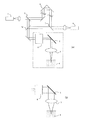
図1(a)は本発明の光学系の構成を示す図で、OCTとOCMの両者を容易に切り替えて観察することができる光学系を示している。この図を用いて本発明の光学系の構成と作用を説明する。
光源1から出た光は、光分岐部材2により参照光路と信号光路に分岐される。参照光路とは、図1(a)においては、光分岐部材2を透過し、折り返しミラー9を経由する光路である。一方、信号光路とは、光分岐部材2により反射される光路である。光分岐部材2により反射された光は、ハーフミラー10を透過して、光束径変換光学系6、光走査系5、対物レンズ3を通過し、試料4に照射される。試料4により反射・散乱された光は、対物レンズ3、光走査系5、光束径変換光学系6を通過し、ハーフミラー10で反射される。参照光路と信号光路は光合成部材7によって合成され、光検出素子8で検出される。
前述のように、OCTとOCMでは試料側の焦点深度が大きく異なるため、両者の観察を行うためには少なくとも2種類の開口数を持つ光学系が必要となる。そこで、本発明の光学系では、光束径変換光学系6を光学系内に配置することで、異なる開口数を持つ光学系に応じた光束径が設定できるようにしている。
光束径変換光学系6は、対物レンズ3に入射する光の光束径を変換することができる。したがって、図1(a)に示したように、光束径変換光学系6により光束径を小さくすることにより対物レンズ3の実質的な開口数は小さくなる。また、光束径変換光学系6により光束径を大きくすることにより、図1(a)の点線内の構成は、図1(b)に示すように、対物レンズ3の開口数を大きくする構成とすることができる。したがって、例えば開口数の小さな対物レンズ3を使用するOCTでの観察と、開口数の大きな対物レンズ3を使用するOCMでの観察の両者を切り替えて行う場合、上記の構成を用いることにより最適な光束径を設定することができる。これにより、どちらの観察の場合も、光量損失を起こさずに対物レンズ3の切り替えを行うことができる。
特に、低コヒーレンス干渉法等により生体試料等を観察する場合には、試料4からの戻り光が微弱であり、光の利用効率の低下は最も避けなければならない事項である。しかしながら、本発明の構成を用いることにより、様々な対物レンズ3に最適な光束径が設定できる。よって、常に高い光の利用効率が実現されるので、高S/N比での観察が可能となる。
なお、光分岐部材2や光合成部材7は、ハーフミラー、ビームスプリッタあるいはファイバカプラーのように、入射した光を透過光と反射光に分岐する境界面を有する光学素子である。また、光束径変換光学系6は、対物レンズ3の瞳をリレーする瞳リレー光学系とすることができる。この構成により、光走査系5を対物レンズ3の瞳位置と共役な位置に配置することも可能となる。
また、図1では対物レンズ3で集光した光を、光走査系5で対物レンズ3の光軸と垂直な方向に走査させているが、光走査系5を固定ミラーにして試料4を保持するステージを光軸と垂直な方向に移動させても良い。
次に、開口数を切り替える別の例として、対物レンズを変換する場合を説明する。対物レンズの光軸に垂直な方向に光を走査する場合、対物レンズの瞳位置あるいは瞳位置と共役な位置においてミラー走査することが望ましい。ところが、対物レンズの瞳の大きさは、対物レンズ毎に異なるのが一般的である。そのため、光束径が常に一定の光学系だと、瞳よりも光束径が小さい場合には所望の開口数が得られない。逆に、光束径が大きい場合には光の利用効率が低下してしまうという問題が生じる。
これに対して、本発明の光学系では光束径変換光学系6を備えているため、対物レンズの瞳径に入射光束の径を一致させることができる。よって、上記のような問題は生じない。また、対物レンズを切り替えてOCT観察とOCM観察の切り替えが行われたとしても、低コヒーレンス干渉の特徴である高いS/N比が損なわれることはない。
次に、図2に、本発明の別の光学系の構成を示す。図1と異なるのは、信号光路の中の、ハーフミラー10から試料4までの光学系である。図2においては、ハーフミラー10を透過した信号光路の光は光走査系5により走査され、瞳リレー光学系11を通過し、対物レンズ3により試料4に照射される。瞳リレー光学系11は、対物レンズ3の瞳13の瞳位置をリレーし、リレーされた位置に光走査系5が配置されている。
ここで、この状態で対物レンズの交換が行われ、対物レンズ3の代わりに別の対物レンズが光路中に配置されたとする。一般的に対物レンズの瞳位置は対物レンズごとに異なる。この場合も、別の対レンズの瞳位置は、対物レンズの瞳13の位置と異なる。そのため、別の対物レンズの瞳は瞳リレー光学系でリレーされるが、光走査系5の位置とは異なる位置にリレーされてしまう。そこで、本発明の光学系では補正機構12を設け、補正機構12によって瞳リレー光学系11で新たにリレーされた瞳の位置と光走査系5の位置を一致させるようにしている。
図2では、補正機構12が移動機構(不図示)を備えており、この移動機構によって瞳リレー光学系11と光走査系5が一体で移動するようになっている。このため、対物レンズ3が交換されても、リレーされた対物レンズの瞳位置と光走査系5の位置を一致させることができる。この結果、光走査系5による光の走査によって光束が瞳13でケラレることがなく、周辺光量不足を防ぐことができる。
なお、図1および図2に示す光学系において、以下のように構成することができる。光分岐部材2から光合成部材7の間の光路、すなわち参照光路又は信号光路あるいはその両方に、音響光学素子(AOM)などの光の周波数を変調する周波数変調部材を有するように構成することができる。これにより、参照光路と信号光路との間の周波数差を利用したヘテロダイン計測を行うことができるため、高S/N比の観察像を得ることができる。
また、参照光路又は信号光路あるいはその両方に、光路長を変化させる光路長調整機構を有するように構成することができる。これにより、試料内の観測点の深さ方向位置を調整したり、又は、走査したりすることが可能となる。
また、その光路長調整機構を、光の周波数を変調可能であるように構成することができる。これにより、光路長調整機構が周波数変調部材の作用を兼ねることができる。
また、光検出素子で検出された光に対し、参照光路と信号光路との間の光の差周波数成分の信号を取得するための信号処理装置を有するように構成することができる。
周波数変調部材や光路長調整機構により、信号光路と参照光路のそれぞれの光の周波数に差を付けることができる。そして、光検出素子により検出される信号のうち、この周波数差に相当する成分の信号を信号処理装置を用いて取得して、ヘテロダイン検出を行うことができる。
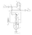
図3に、本発明の光学装置の構成を示す。光源1を出た光は、光分岐部材2により参照光路と信号光路に分岐される。光分岐部材2を透過する参照光路の光は、光路長調整機構21を通過して、光合成部材7に到達する。一方、光分岐部材2により反射された信号光路の光は、ハーフミラー10を透過し、光走査系22により反射され、対物レンズ25又は26を通過して試料4に照射される。試料4は走査ステージ24に保持されている。試料4内の観測点(対物レンズによる集光位置)29で反射・散乱された光は、対物レンズ25又は26、光走査系22を通過し、ハーフミラー10で反射され、光合成部材7に到達する。光合成部材7で参照光路と信号光路の光が合成され、光検出素子8で検出される。
本発明の光学装置では光路長調整機構21が参照光路に配置されており、参照光路の光路長を変化させることができるようになっている。具体的には、光路長調整機構21は反射型あるいは透過型の光学素子と移動機構を備えており、この光学素子を移動させることによって光路長を変化させている。そして、この光路長を変化させることによって、試料4の内部において、信号光路の光路長が参照光路の光路長が一致する位置を変えることができるようになっている。よって、光路長調整機構21は試料4内の観測点29と試料4を相対的に、対物レンズ25の光軸に沿う方向(第1の方向)に移動させる機構である。
走査系は光走査系22と走査ステージ24で構成されている。このうち、走査ステージ24は第1の走査機構であって、試料4を第1の方向に移動させる。そして、光走査系22は第2の走査機構であって、試料4内の観測点29を対物レンズ25の光軸と垂直な方向(第2の方向)に移動させる。よって、図3の構成においては、第1の方向はz方向、第2の方向はx方向に一致する。なお、2つの瞳リレー光学系11によって、対物レンズの瞳13、23は光走査系22の位置にリレーされている。瞳位置の違いは図2の補正機構12によって行われる。
走査制御機構27は光走査系22と走査ステージ24の走査速度、及び光路長調整機構21の光学素子の移動速度(走査速度)を制御する機能を備えている。そして更に、走査制御機構27は、第1の方向への走査機構として、走査ステージ24と光路長調整機構21のいずれか一方を選択する機能を備えている。
以上が本発明の光学装置の基本構成であるが、対物レンズとしてはLc≧Dfを満たす開口数を有する対物レンズを少なくとも1つ使用するのが好ましい。ここで、Dfは一般的に焦点深度と呼ばれる値で、対物レンズの開口数をNA、光源の中心波長をλcとした場合、Df=λc/(NA)2 の式より求まる値である。また、Lcは試料に入射する光の可干渉距離である。
また、Lc≧Dfを満たす開口数を有する対物レンズの他に、Lc<Dfを満足する開口数を有する対物レンズを少なくとも1つ備えることもできる。そして、Lc≧Dfを満足する対物レンズとLc<Dfを満足する対物レンズの両方を備える場合、走査制御機構27は対物レンズの切替に応じて走査速度の設定と第1の方向への走査機構の選択を行う。
ここで、対物レンズについて説明する。対物レンズ25は、Lc<Dfを満たす開口数を有する対物レンズである。この対物レンズ25の焦点深度は試料4に入射する光源1からの光の可干渉距離(コヒーレンス長)よりも長いため、OCTによる観測に適している。一方、対物レンズ26は、Lc≧Dfを満たす開口数を有する対物レンズである。この対物レンズ26の開口数は対物レンズ25の開口数よりも大きく、OCMによる観測に適している。
なお、本発明の構成においては、後述するように、対物レンズ25を使用せず、対物レンズ26のみによって構成することも可能である。しかしながら、説明を容易にするため、ここではそれぞれの対物レンズを使用する構成とする。また、同じく説明を容易とするため、それぞれの対物レンズの開口数を満足するように、光源からの光が対物レンズの瞳全てを通過するものとする。したがって、対物レンズ25はOCT用、対物レンズ26はOCM用となる。
次に、走査制御機構27の作用を説明する。走査制御機構27は、使用する対物レンズのDfの値に応じて、第1の方向への走査機構として走査ステージ24と光路長調整機構21のいずれか一方を選択する。そして、光走査系22と選択された第1の方向への走査機構の走査速度を決定する。
Lc<Dfの場合、つまり対物レンズ25を用いる場合であるから光学装置はOCTとなる。OCTでは、コヒーレンス長がz方向の分解能を決定する。そこで、走査制御機構27は第1の方向への走査機構として光路長調整機構21を選択する。これにより、試料4内で信号光路の光路長が参照光路の光路長と一致する位置が変化することになる。この時、対物レンズ25と試料4との相対的な位置は変化しない。そして、光路長調整機構21における光学素子の走査速度をv1、光走査系22の走査速度をv2とすると、走査制御機構27はv1>v2となるように各々の速度を設定する。
このように、Lc<Dfの場合は、光路長調整機構21の走査速度(第1の方向の走査速度)を光走査系22の走査速度(第2の方向の走査速度)よりも速く設定して、x−z断面画像を観測する。なお、第1の方向の走査を速く行うことは、光路長調整機構21の走査で発生するドップラー周波数を利用したヘテロダイン干渉計測において、実用的なドップラー周波数を得る上で有効である。
一方、Lc≧Dfの場合、つまり、ここでは対物レンズ26を用いる場合であるから光学装置はOCMとなる。OCMでは、焦点深度がコヒーレンス長以下となるため、観測点29を第1の方向に走査するには、対物レンズ26と試料4との相対的な位置を変化させる必要がある。そこで、走査制御機構27は第1の方向への走査機構として走査ステージ24を選択する。そして、走査ステージ24の走査速度をv1、光走査系22の走査速度をv2とすると、v2>v1となるように各々の速度を設定する。
光走査系22の具体的構成としては走査ミラーが考えられる。走査ミラーを使用した場合、走査ステージ24による走査は、走査ミラーによる走査に比べて一般的に速度が遅い。したがって、試料のx−z断面画像をできるだけ高速に観測するためには、第2の方向の走査を第1の方向よりも高速に行うのが最も効率的である。つまり、走査速度はv2>v1と設定されるのが望ましい。
なお、図3では走査ステージ24により第1の方向を走査しているが、走査ステージ24を固定して対物レンズ26を第1の方向に移動させる機構にすることも可能である。そして、上記のような走査速度の設定は、第1の方向の走査を対物レンズ26で行う場合にも好ましい。特に、第1の方向における観察範囲がコヒーレンス長よりも大きい場合には、対物レンズ26による観測点29の移動に応じて、光路長調整機構21による光路長の調整も必要となる。よって、対物レンズ26の走査速度v1を光走査系22の走査速度v2より小さくすることにより、光路長の調整を行うことができる。
このように、走査制御機構27は使用する対物レンズの切替に応じて、以下のように走査速度の設定と第1の方向への走査機構の選択を行う。
Lc<Dfのとき、v1>v2
Lc≧Dfのとき、v2>v1
ここで、Dfは信号光路に配置される対物レンズの開口数をNA、光源の中心波長をλcとした場合、Df=λc/(NA)2 の式より求まる値、Lcは試料に入射する光の可干渉距離、v1、v2はそれぞれ第1の方向への走査速度、第2の方向への走査速度である。
図3に示す構成では、説明を容易とするために、対物レンズ25と26の交換によりOCTとOCMの切り替えを行っている。しかしながら、本発明の光学装置の基本構成において、対物レンズ26のみでOCTとOCMの観察も可能である。例えば、対物レンズ26に入射する光の光束を絞ると有効開口数が小さくなり、対物レンズ26は実質的に対物レンズ25と同じになる。このようにすれば、1つの対物レンズによりOCT及びOCMを行う構成も可能である。なお、有効開口数とは、実際に対物レンズ26に入射する光束径によって決まる試料側の開口数である。
この場合、走査制御機構27は以下の使用する対物レンズの有効開口数に応じて、以下のように走査速度の設定と第1の方向への走査機構の選択を行う。
Lc<Df' のとき、v1>v2
Lc≧Df' のとき、v2>v1
ここで、Df' は信号光路に配置される対物レンズの有効開口数をNA' 、光源の中心波長をλcとした場合、Df' =λc/(NA' )2 の式より求まる値、Lcは試料に入射する光の可干渉距離、v1、v2はそれぞれ第1の方向への走査速度、第2の方向への走査速度である。
さて、図3の光学装置では光路長調整機構により周波数変調を行い、テロダイン干渉計測を行っている。しかしながら、これとは別に、音響光学素子のような光路長変化を伴わない周波数変調部材を配置して、ヘテロダイン干渉計測をすることができる。この場合の構成は、図3に示す構成と略同じであるが、参照光路又は信号光路あるいはその両方に、光路長変化を伴うことなく光の周波数を変調する周波数変調部材を配置する点が異なる。また、走査制御機構27の動作において、Lc<DfあるいはLc<Df' の場合も走査速度をv2>v1に設定するという点で異なる。
光路長調整機構21によって周波数変調が行われることは図3で説明した。しかしながら、図3に示したような折り返しミラーを駆動する構成では、光路長の調整範囲全体にわたって変調周波数を一定に保つことは難しい。このため、図3のような光路長調整機構21だと、ドップラー周波数に広がりが生じS/N比の低下を招くおそれがある。
これに対して、音響光学素子のような周波数変調部材では、常に一定の周波数変調が行われる上、光路長変化を伴わない。したがって、光路長調整機構21で周波数変調を行う必要がない。また、Lc<Df' の場合においても、Lc≧Df' の場合と同じく、走査速度をv2>v1と設定することができ、光路長調整機構21を高速に駆動する必要がない。前にも述べたが、光走査系22の具体的手段としての走査ミラーは一般的に高速駆動が可能であるため、本発明の構成は、時間分解能を要求される観察においては特に有効である。
このように、参照光路又は信号光路あるいはその両方に、光路長変化を伴うことなく光の周波数を変調する周波数変調部材を配置しておくと、周波数変調のための機械的駆動機構が不要となる。よって、特に前述のOCMにおいてより高速な観測を行うことができるので好ましい。
この場合、走査制御機構27はLcとDfあるいはLcとDf' の大小に関わらず、走査速度を以下のように設定するとともに、第1の方向への走査機構の選択を行う。
v2>v1
なお、使用する対物レンズのDfあるいはDf' の値に応じて、走査速度を切替える構成を説明したが、この構成においても参照光路又は信号光路あるいはその両方に、光路長変化を伴うことなく光の周波数を変調する周波数変調部材を配置することも当然できる。
図4に、本発明の別の光学装置の構成を示す。
光源1を出た光は、光分岐部材2により参照光路と信号光路に分岐される。光分岐部材2を透過する参照光路の光は、光路長調整機構31を通過して、光合成部材7に到達する。一方、光分岐部材2により反射された信号光路の光は、ハーフミラー10を透過し、第2の方向に光を走査する光走査系32により反射される。光走査系32により反射された光は、瞳リレー光学系11を通過して第3の方向に光を走査する光走査系33に入射する。光走査系33で反射された光は、瞳リレー光学系11を通過して対物レンズ35又は36に入射し、試料4に照射される。試料4は走査ステージ34に保持されている。試料4内の観測点(対物レンズによる集光位置)29で反射・散乱された光は、対物レンズ35又は36、瞳リレー光学系11、光走査系33、32を通過し、ハーフミラー10で反射され、光合成部材7に到達する。光合成部材7で参照光路と信号光路の光が合成され、光検出素子8で検出される。
図4の光学装置においても、光路長調整機構31が参照光路に配置されており、参照光路の光路長を変化させることができるようになっている。また、走査系は光走査系32、33と走査ステージ24で構成されている。このうち、走査ステージ24は第1の走査機構であって、試料4を第1の方向に移動させる。そして、光走査系32は第2の走査機構であって、試料4内の観測点29を対物レンズ25の光軸と垂直な方向(第2の方向)に移動させる。また、光走査系33は第3の走査機構であって、試料4内の観測点29を第1及び第2の方向と垂直な方向(第3の方向)に移動させる。よって、図3の構成においては、第1の方向はz方向、第2の方向はx方向、第3の方向はy方向に一致する。なお、2つの瞳リレー光学系11によって、対物レンズの瞳13あるいは23は光走査系32と33の位置にリレーされている。対物レンズの瞳13と23の瞳位置の違いは、図2の補正機構12によって行われる。
走査制御手段37は光走査系32、33と走査ステージ34の走査速度、及び光路長調整機構31の光学素子の移動速度(走査速度)を制御する機能を備えている。そして更に、走査制御手段37は、第1の方向への走査機構として、走査ステージ34と光路長調整機構31のいずれか一方を選択する機能を備えている。
以上が本発明の別の光学装置の基本構成であるが、対物レンズとしてはLc≧Dfを満たす開口数を有する対物レンズを少なくとも1つ使用するのが好ましい。ここで、Dfは一般的に焦点深度と呼ばれる値で、対物レンズの開口数をNA、光源の中心波長をλcとした場合、Df=λc/(NA)2 の式より求まる値である。また、Lcは試料に入射する光の可干渉距離である。
また、Lc≧Dfを満たす開口数を有する対物レンズの他に、Lc<Dfを満足する開口数を有する対物レンズを少なくとも1つ備えることもできる。そして、Lc≧Df満足する対物レンズとLc<Df満足する対物レンズの両方を備える場合、走査制御機構37は対物レンズの切替に応じて走査速度の設定と第1の方向への走査機構の選択を行う。 Lc<Dfの場合、つまり、ここでは対物レンズ35を用いる場合であり、光学装置はOCTとなる。OCTでは、コヒーレンス長がz方向の分解能を決定する。そこで、走査制御機構37は第1の方向への走査機構として光路長調整機構31を選択する。これにより、試料4内で信号光路の光路長が参照光路の光路長と一致する位置が変化することになる。この時、対物レンズ35と試料4との相対的な位置は変化しない。そして、光路長調整機構31における光学素子の走査速度をv1、光走査系32の走査速度をv2、光走査系33走査速度をv3とすると、走査制御機構37はv1>v2>v3となるように各々の速度を設定する。
このように、Lc<Dfの場合は、光路長調整手段31の走査速度(第1の方向の走査速度)を走査系32の走査速度(第2の方向の走査速度)よりも速く設定して、x−z断面画像を観測する。そして、走査系33の走査速度(第3の方向の走査速度)を走査系32の走査速度よりも更に遅く設定して、y方向ごとのx−z断面画像が得られるようにしている。これにより、図4の光学装置では試料4の3次元画像が得られる。なお、第1の方向の走査を速く行うことは、光路長調整手段21の走査で発生するドップラー周波数を利用したヘテロダイン干渉計測において、実用的なドップラー周波数を得る上で有効である。
一方、Lc≧Dfの場合、つまり、ここでは対物レンズ36を用いる場合であり、光学装置はOCMとなる。OCMでは、焦点深度がコヒーレンス長以下となるため、観測点39を第1の方向に走査するには、対物レンズ36と試料4との相対的な位置を変化させる必要がある。そこで、走査制御機構37は第1の方向への走査機構として走査ステージ34を選択する。そして、走査ステージ34における光学素子の走査速度をv1、光走査系32の走査速度をv2、光走査系33の走査速度をv3とすると、走査制御機構37はv2>v3>v1となるように各々の速度を設定する。
このように、Lc≧Dfの場合は、走査ステージ34の走査速度(第1の方向の走査速度)を光走査系32の走査速度(第2の方向の走査速度)や光走査系33の走査速度(第3の方向の走査速度)よりも遅く設定して、x−y断面画像を優先的に観測する。そして、x−y断面画像の取得後に走査ステージ34を移動させ、新たなz位置でのx−y断面画像が得られるようにしている。これにより、試料4の3次元画像が得られる。
光走査系32、33の具体的構成としては走査ミラーが考えられる。走査ミラーを使用した場合、走査ステージ34による走査は、走査ミラーによる走査に比べて一般的に速度が遅い。したがって、試料4の3次元画像をできるだけ高速に観測するためには、第2の方向及び第3の方向の走査を第1の方向よりも高速に行うのが最も効率的である。つまり、走査速度はv2>v3>v1と設定されるのが望ましい。
また、図3の光学装置でも説明したように、走査ステージ34を固定して対物レンズ36を第1の方向に移動させる機構にすることも可能である。そして、上記のような走査速度の設定は、第1の方向の走査を対物レンズ36で行う場合にも好ましい。特に、第1の方向における観察範囲がコヒーレンス長よりも大きい場合には、対物レンズ36による観測点39の移動に応じて、光路長調整機構31による光路長の調整も必要となる。よって、対物レンズ36の走査速度v1を光走査系22、23の走査速度v2、v3より小さくすることにより、光路長の調整を行うことができる。
このように、走査制御機構37は使用する対物レンズの切替に応じて、以下のように走査速度の設定と第1の方向への走査機構の選択を行う。
Lc<Dfのとき、v1>v2>v3
Lc≧Dfのとき、v2>v3>v1
ここで、Dfは信号光路に配置される対物レンズの開口数をNA、光源の中心波長をλcとした場合、Df=λc/(NA)2 の式より求まる値、Lcは試料に入射する光の可干渉距離、v1、v2、v3はそれぞれ第1の方向への走査速度、第2の方向への走査速度、第3の方向への走査速度である。
また、本発明の別の光学装置の基本構成においても、対物レンズ36のみでOCTとOCMの観察も可能である。これは図3の光学装置で説明したように、対物レンズ36に入射する光の光束を絞り有効開口数を小さくすれば良い。この結果、対物レンズ36は実質的に対物レンズ35と同じになるのでOCT用の対物レンズとなる。よって1つの対物レンズでOCT及びOCMを行う構成も可能である。
この場合、走査制御機構37は以下の使用する対物レンズの有効開口数に応じて、以下のように走査速度の設定と第1の方向への走査機構の選択を行う。
Lc<Df' のとき、v1>v2>v3
Lc≧Df' のとき、v2>v3>v1
ここで、Df' は信号光路に配置される対物レンズの有効開口数をNA' 、光源の波長をλcとした場合、Df' =λc/(NA' )2 の式より求まる値、Lcは試料に入射する光の可干渉距離、v1、v2、v3はそれぞれ第1の方向への走査速度、第2の方向への走査速度、第3の方向への走査速度である。
また、参照光路又は信号光路あるいはその両方に、光路長変化を伴うことなく光の周波数を変調する周波数変調部材を配置することができる。この点については図3の光学装置で説明したとおりで、光路長調整機構31において周波数変調を行う必要がなくなる。そのため、走査制御機構37は使用する対物レンズの開口数あるいは有効開口数に応じて、以下のように走査速度の設定と第1の方向への走査機構の選択を行う。
Lc<DfあるいはLc<Df' のとき、
v2>v1>v3又はv2>v3>v1
Lc≧DfあるいはLc<Df' のとき、
v2>v3>v1
ここで、Dfは信号光路に配置される対物レンズの開口数をNA、光源の波長をλcとした場合、Df=λc/(NA)2 の式より求まる値、Df' は信号光路に配置される対物レンズの有効開口数をNA' 、光源の波長をλcとした場合、Df' =λc/(NA' )2 の式より求まる値、Lcは試料に入射する光の可干渉距離、v1、v2、v3はそれぞれ第1の方向への走査速度、第2の方向への走査速度、第3の方向への走査速度である。
このように、参照光路又は信号光路あるいはその両方に、光路長変化を伴うことなく光の周波数を変調する周波数変調部材を配置することにより、特に前述のOCMにおいて、より高速な観測を行うことができる。前にも述べたが、走査系32、33の具体的手段としての走査ミラーは一般的に高速駆動が可能であるため、このような構成は、時間分解能を要求される観察においては特に有効である。
また、図3あるいは図4に示した光学装置において、光束径の大きさを変える光束径変換光学系を配置することもできる。この場合、光束径変換光学系は、光が光走査系に入射するかあるいは光走査系から射出される位置に配置すれば良い。この構成により、OCTやOCMにおいて、所望の有効開口数を設定したり、あるいは対物レンズを交換した際に光の利用効率の低下を防ぐことができる。
また、その光束径変換光学系は、対物レンズの瞳をリレーする瞳リレー光学系とすることができる。この構成により、第2の方向あるいは第3の方向への走査を行う走査系を、対物レンズの瞳位置と共役な位置に配置することも可能となる。
また、瞳リレー光学系によってリレーされた対物レンズの瞳位置と光走査系の位置を、略一致させる補正機構を設けても良い。この構成により、対物レンズの交換によって対物レンズの瞳位置が異なる場合においても、リレーされた瞳位置と光走査系の位置をほぼ一致させることができる。これにより、第2の方向あるいは第3の方向への走査を行う光走査系が対物レンズの瞳位置と常に共役な位置になるように構成でき、周辺光量不足等を防ぐことができる。
また、対物レンズの有効開口数の変化及びこれに付随する光学系の変化により、信号光路と参照光路との分散特性に差が生じる場合がある。そこで、この分散特性の差を補償する分散調整素子を設けるのが良い。更に、その分散調整素子は、分散調整量を選択的に又は連続的に調整可能であれば好ましい。
光源からの光として、スペクトルに幅を持つ光を使用した場合を考える。この光が光路中に配置された光学素子を通過するとき、その光学素子の分散特性に応じて波長によりその光路長が異なるという現象が起きる。例えば、光源のスペクトル分布が図10(a)に示されるものであった場合に、図10(b)で示した分散特性を持つ光学素子を光が通過すると、図10に示す波長λ1の光の光路長は波長λhの光の光路長よりも長くなる。本発明の光学系あるいは光学装置において干渉計測を行う場合には、波長による光路長の差があると、S/N比の低下を招く。信号光路と参照光路との分散特性の差は、光束径変換光学系や補正機構による信号光路の光学系の変更、あるいは対物レンズの開口数(有効開口数)を変化させる操作に伴って発生する。そこで、上述の分散調整素子を用いることにより、信号光路と参照光路との分散特性の差を補償することができる。その結果、干渉計測におけるS/N比を向上させることができる。
また、対物レンズの有効開口数の変化及びこれに付随する光学系の変化により発生する光路長の変化分を、光路長調整量として光路長調整機構により補償するように構成することができる。この構成を用いることにより、上述の分散調整素子と同様に光路長変化分を補償することができる。
また、分散調整量又は光路長調整量あるいはその両方を記憶するための記憶手段を有するように構成しておくことが好ましい。これまで述べたように、OCTとOCMを切り替えて使用する方法の一つとして、1つの対物レンズの有効開口数を変化させる方法がある。この場合、効率的でかつ高S/N比の観察を行うためには、有効開口数の変化に伴って分散の調整又は光路長の調整あるいはその両方を正確に行う必要がある。一方、様々な試料に最適な倍率で観察するためには、対物レンズを何種類も交換する必要がある。この場合、有効開口数も様々に変化するため、それに伴う分散の調整量や光路長調整量の組み合せも多くなる。
そのため、有効開口数が変化する度にそれぞれの最適な調整量を探るのは、観察操作を行う上で非常に煩雑となる。そこで、記憶手段で分散調整量又は光路長調整量あるいはその両方を予め記憶しておくことで、分散や光路長の調整操作時にこれを参照することができる。
また、光源は低コヒーレンス光源であることが好ましい。この構成により、低コヒーレンス干渉観察を行うことができる。
また、本発明の光学系を有する顕微鏡を構成することができる。これまでに述べた光学系を顕微鏡に組み込むか、あるいは顕微鏡に接続することで、顕微鏡システムの操作性を生かした効率的な観察を行うことができる。
また、以上の光学系を顕微鏡から取り外し可能にすることができる。この構成により、新規に顕微鏡システムを構築することなく、従来の顕微鏡にその光学系を後付けすることができる。また、1つの光学系を異なる複数の顕微鏡に取り付けることも可能となる。
以上述べたように、本発明の光学系と光学装置は、OCT、OCMのどららの観察においても、画像取得に要する時間をできるだけ短くできることができる。したがって、生体試料を特にin vivoで観測する場合には、細胞や組織の動きを高い時間分解で観測したいという要求に応えることが可能となる。また、OCTとOCMを切り替えた場合に、S/N比の低下を招くこともない。
以下、本発明の光学系及び光学装置の実施例を、図面を参照にして説明する。
(実施例1)
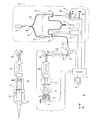
図5(a)は、本発明による光学系の実施例を示したものである。この実施例は低コヒーレンス干渉光学系の例であって、試料内の対物レンズの光軸に平行な断面の画像を観察するための光学系である。
図5(a)において、低コヒーレンス光源101からの光は、ファイバーカップラー102へ光ファイバーで導かれる。ファイバーカップラー102からの光は参照光路103と信号光路104に分岐される。参照光路103の光は、AOM(音響光学素子)131を通過し、コリメータレンズ105で平行光として射出され、可動ミラー106で反射される。可動ミラー106による反射光はコリメータレンズ105より再び同じ光路を戻り、AOM131を通過してファイバーカップラー102に到達する。
一方、信号光路104の光は、AOM132を通過し、シングルモードファイバー端191を射出し、コリメータレンズ107で平行光として射出される。そして、射出した光はx方向の走査を行うガルバノミラー108で反射し、光束径変換光学系115内の瞳リレー光学系109を通過し、対物レンズ110により試料111に照射される。試料111内の観測点112からの散乱光は、再び対物レンズ110、瞳リレー光学系109、ガルバノミラー108、コリメータレンズ107、AOM132を通ってファイバーカップラー102に到達する。参照光路103と信号光路104からの戻り光はファイバーカップラー102で合成され、光検出器114で検出される。光検出器114の出力は、信号処理装置133に入力される。この光学系においては、光分岐素子と合成素子が1つのファイバーカップラー102により構成されている。
本実施例では、コリメータレンズ105、可動ミラー106、及び可動ミラー106を移動させる図示されていない移動機構が光路長調整機構を構成している。可動ミラー106を高速で変位させることにより光の周波数のドップラーシフトが起こる。また、AOM132、133を動作させることにより、各光路の光の周波数が変調される。これらを選択的に使用するか、又は組み合わせて使用することができる。参照光路103と信号光路104の光の差周波数成分を信号処理装置133で検出することにより、参照光路103と信号光路104のヘテロダイン干渉計測を行うことができる。
次に、信号光路の動作について説明する。対物レンズ110の瞳113は瞳リレー光学系109でリレーされる。ガルバノミラー108は、瞳リレー光学系109によってリレーされた瞳位置に配置されている。
対物レンズ110は、焦点深度が大きい、つまり、開口数の小さな対物レンズである。一方、図5(b)は開口数の大きな対物レンズ120である。ここで、図5(b)は、図5(a)において、対物レンズ110を対物レンズ120に切り替えられたときの光学系であって、ガルバノミラー108以降の光学系について示したものである。したがって、OCT観察を行う場合には、対物レンズ110が使用される。一方、OCM観察の場合は対物レンズ120が用いられ、シングルモードファイバー端191を共焦点ピンホールとする共焦点光学系による観察を行うことができる。
ここで、対物レンズ120の瞳123の瞳径は、対物レンズ110の瞳113の瞳径よりも小さい。このため、対物レンズ120を使用する場合には、光束径変換光学系115により瞳リレー光学系109を別の瞳リレー光学系119に変換する。ガルバノミラー108から対物レンズの瞳への瞳リレー倍率は、瞳リレー光学系109よりも瞳リレー光学系119の方が小さくなるように設定されている。したがって、ガルバノミラー108から射出される光束の径を、対物レンズの瞳径に一致させることできる。これにより、光源101からの光を無駄なく使用することができる。
さらに、対物レンズ120の瞳123の対物レンズ120内での位置は、対物レンズ110のそれとは異なっているが、瞳リレー光学系119によって瞳123はガルバノミラー108と共役になっている。すなわち、本実施例では、リレーされた対物レンズの瞳位置がガルバノミラー108に略一致しているから、光束径変換光学系115が補正機構としても作用していることになる。
(実施例2)
図6(a)は、本発明による光学装置の実施例を示したものである。本実施例は低コヒーレンス干渉光学装置の例であって、試料内の対物レンズの光軸に平行な断面の画像を観察するための光学装置である。
図6(a)において、低コヒーレンス光源201からの光は、ファイバーカップラー202へ光ファイバーで導かれる。ファイバーカップラー202からの光は参照光路203と信号光路204に分岐される。参照光路203の光は、AOM231を通過し、ファイバー端241を射出の後、コリメータレンズ242で平行光に変換され、別のコリメータレンズ243を通過してファイバーカップラー222に導かれる。
一方、信号光路204の光は、AOM232を通過し、サーキュレーター246を通過後、シングルモードファイバー端291から射出され、コリメータレンズ207で平行光に変換される。その後、光束径変換光学系215を通過し、x方向の走査を行うガルバノミラー208で反射され、瞳リレー光学系209を通過し、対物レンズ210により試料211を照射する。試料211は、z方向に移動可能なステージ216に固定されている。試料211内の観測点212からの散乱光は、再び対物レンズ210、瞳リレー光学系209、ガルバノミラー208、光束径変換光学系215、コリメータレンズ207を通り、サーキュレーター246を通過してファイバーカップラー222に到達する。参照光路203と信号光路204からの光はファイバーカップラー222で合成され、光検出器214で検出される。光検出器214の出力は、信号処理装置233に入力される。
まず、信号光路の動作について説明する。本実施例では、低コヒーレンス光源201は、中心波長1.3μm、コヒーレンス長20μmの光源である。そして、図6(a)の対物レンズ210には開口数0.5のものを用いている。このとき、
Lc=20μm
Df=5.2μm
となるので、対物レンズ210は、Lc≧Dfを満たしている。
図6(a)においては、対物レンズ210に入射する光束径は、対物レンズ210の瞳213の瞳径に一致している。このため、有効開口数は対物レンズ210の開口数に等しい。したがって、この状態においてはOCMによる観察を行うことができる。そこで、走査制御機構270は、第1の方向(z方向)の走査機構としてステージ216を選択し、振動周波数を10Hzに設定する。また、第2の方向(x方向)の走査機構であるガルバノミラー208の振動周波数を4kHzに設定する。
本実施例の光学装置では、観察範囲をx:400μm、z:400μmとし、x−z断面の1画像の走査時間を0.1秒に設定している。そして、得られる画素数を400×400画素とすると、上記振動周波数を平均走査速度に換算すれば、x:3.2m/秒(=v2)、z:8mm/秒(=v1)となり、v2>v1となっている。つまり、x方向に高速走査を行い、z方向は相対的に低速で走査を行うことで、x−z画像を得る。なお、干渉信号の計測については、参照光路及び信号光路に配置されたAOM231及び232の変調周波数の差周波数を用いたヘテロダイン計測を行う。差周波数成分の検出は信号処理装置233により行われる。
一方、図6(b)は、図6(a)と同じ対物レンズ210を用いてOCT観察を行う例である。ここでは、図6(a)のうち、コリメータレンズ207より後の光学系を抜き出して示している。光束径変換光学系215は光束径変換光学系219を有しており、光束径変換光学系219をコリメータレンズ207とガルバノミラー208の間に挿入できる機構となっている。光束径変換光学系219は、コリメータレンズ207から射出される平行光束の光束径を縮小する倍率を有している。例えば、この光束径変換光学系219が光路中に挿入された場合、対物レンズ210の有効開口数は0.035となるように倍率が設定されている。このとき、Df' は、
Df' =約1mm
となるので、図6(b)の光学系では、Lc<Df' を満たしていることになる。
図6(b)の光学系でのOCT観察においても、x−z断面の1画像の走査時間を0.1秒に設定している。OCTでは、一般的に、第1の方向(z方向)の走査は、例えば図5(a)における可動ミラー106を高速に振動させ、このとき発生するドップラー周波数を利用したヘテロダイン計測を行うことが多い。しかしながら、本実施例では、OCTの場合においても、AOM231及び232によって生じる変調周波数を用いてヘテロダイン計測を行う。このため、z方向への高速走査は必要ない。そこで、走査制御機構270は第1の方向の走査速度v1と第2の方向の走査速度v2について、図6(a)と同じく、v2>v1となるように設定する。
この設定により、第2の方向の走査においては、図6(a)と同じガルバノミラー208を同じ走査速度で駆動することが可能で、ガルバノミラー208の制御機構が簡易的なものとなる。一方、第1の方向の走査機構については、ステージ216又は参照光路の光路長調整機構260を用いることができる。ステージ216を用いた場合には、光路長調整手段260には走査機構が不要となるメリットがある。
このように、本実施例では、OCTとOCMの両者の観察において、対物レンズ、x方向走査機構・走査速度、z方向走査機構、ヘテロダイン計測のための光変調手段を全て共通化することができる。
次に、参照光路の光路長調整機構260について説明する。光路長調整機構260の主な構成要素は、コリメータレンズ242、243、駆動ステージ245、駆動部244である。ファイバー端241とコリメータレンズ242は駆動部244に固定されている。駆動部244は駆動ステージ245上を移動する。これにより、コリメータレンズ242と243の間の光路長が変化し、光路長の調整が行われる。
光束径変換光学系215において、光束径変換光学系219を信号光路に挿脱すると、OCM用の図6(a)の光学系とOCT用の図6(b)の光学系が切り替わる。このとき、光束径変換光学系219の挿脱によって、新たな光路長の変化が起こる。光路長の変化が起こると、OCMとOCTでの観測位置が大きく異なる可能性がある。さらには、観測点212が試料211から外れてしまう可能性もある。そのため、これらの可能性を無くすために、何らかの光学的な補償をする必要がある。
そこで、光路長調整機構260の駆動部244を上記光路長の変化分に相当する距離だけ移動させて、光路長変化の影響をなくすことができる。また、本実施例では、光路長調整量の記憶手段として、指示マーク261が駆動部244に、また、調整用目盛262、263が駆動ステージ245に記されているため、容易に光路長調整量の切り替えが行える。
また、コリメータレンズ242と243の間には、例えばプリズムや回折格子のような分散調整素子251が挿脱可能であるように構成されている。これは、信号光路と参照光路の間で発生する分散特性の差を補償するものである。なお、この分散特性の差は、光束径変換光学系219の信号光路への挿脱により発生する。これにより、光学系の切り替えに伴うS/N比の低下を防ぐことができる。
本実施例においては、走査制御機構270、光束径変換光学系215、光路長調整機構260及び分散調整素子251を電気的に制御し、OCTとOCMの切り替えに係わる煩雑な操作を全て自動的に行うことも可能である。
(実施例3)
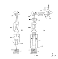
図7(a)は、本発明による光学装置の別の実施例を示したものである。本実施例も低コヒーレンス干渉光学装置の例であって、試料内の3次元画像を観察するための光学装置である。
図7(a)において、低コヒーレンス光源301からの光は、ファイバーカップラー302へ光ファイバーで導かれる。ファイバーカップラー302からの光は参照光路303と信号光路304に分岐される。参照光路303の光は、AOM331、サーキュレーター347を通ってコリメータレンズ342で平行光に変換される。さらに、分散調整素子351を通過し、可動ミラー306で反射される。反射光は、再び分散調整素子351、コリメータレンズ342、サーキュレータ347を通って、ファイバーカップラー322に到達する。
一方、信号光路304の光は、AOM332、サーキュレーター346を通り、シングルモードファイバー端391から射出される。そして、コリメータレンズ307を通過し、ガルバノミラー318で反射され、瞳リレー光学系319を通過し、ガルバノミラー308に入射する。ガルバノミラー308で反射された光は、瞳リレー光学系309を通過後、対物レンズ310により試料311に照射される。試料311は、ステージ316に固定されている。
試料311内の観測点312からの散乱光は、再び対物レンズ310、瞳リレー光学系309、ガルバノミラー308、瞳リレー光学系319、ガルバノミラー318、コリメータレンズ307を通過し、サーキュレーター346を通って、ファイバーカップラー322に到達する。参照光路303と信号光路304からの光はファイバーカップラー322で合成され、光検出器314で検出される。光検出器314の出力は、信号処理装置333に入力される。
本実施例では、低コヒーレンス光源301は、中心波長1.3μm、コヒーレンス長20μmの光源である。対物レンズ310には、開口数0.5のものを用い、図7(a)においてOCM観察用の光学系を構成している。このとき、 Lc=20μm
Df=5.2μm
となるので、対物レンズ310は、Lc≧Dfを満たしている。一方、図7(b)はOCT観察用の光学系の一部で、図7(a)におけるガルバノミラー308以降を抜き出して示したものである。対物レンズ320の開口数は0.025であり、
Df=約2mm
となるので、対物レンズ320は、Lc<Dfを満たしている。
本実施例では、第2の方向(x方向)と第3の方向(y方向)の走査用に、ガルバノミラー308、318を有している。また、第1の方向(z方向)の走査用に、ステージ316又は光路長調整機構(可動ミラー306)を有している。
よって、OCT観察、OCM観察の両者において、3次元観察が可能である。
本実施例における対物レンズ310と320では、それぞれの瞳313及び323の瞳径及び瞳位置が異なっている。対物レンズの瞳位置と走査ミラー位置が共役な位置関係になっていないと、ケラレが生じることは先に説明したとおりである。そこで、本実施例では、光束径を瞳径と一致すさせるため、対物レンズ320を使用する際に、光束径変換光学系としてアダプターレンズ(光束径変換光学系)373を、瞳リレー光学系309と対物レンズ320の間に配置する。この構成の利点は、瞳リレー光学系309を変更する必要がないという点である。図7(b)のOCT観察においては、x−z断面の2次元像を観察し、その画像において注目する領域を、図7(a)のOCM観察により3次元で観察を行うという設定をしている。まず、OCT観察では、対物レンズ320を使用し、アダプターレンズ373を光路内に挿入する。第1の方向の走査は参照光路303内の可動ミラー306により行い、第2の方向の走査は走査ミラー308により行う。ここでは、可動ミラー306の走査による光周波数のドップラーシフトを利用したヘテロダイン干渉計測を行うため、走査速度は第2の方向よりも第1の方向の方が速く設定される。走査速度の設定は、走査制御機構としてのコンピュータ371により制御されている。
次に、OCM観察を行う場合には、対物レンズ310が光路中に挿入され、アダプターレンズ373が光路から外れる。第2及び第3の方向の走査は、それぞれ走査ミラー308、318により行われる。また、第1の方向の走査はステージ316により行われる。3次元画像の取得は、まず、x−y断面の2次元像を取得し、これをz方向に走査することにより行う。そのため、z方向の走査が最も遅くなるように設定される。
第1の方向の走査機構を光路長調整機構(可動ミラー306)からステージ316へ切り替える操作、及び各走査機構の走査速度の設定は、コンピュータ371により制御される。また、OCM観測の場合、ヘテロダイン干渉計測のための光周波数変調部材には、AOM331及び332が用いられる。また、OCT、OCMのそれぞれのヘテロダイン検波においては、可動ミラー306によって生じるドップラー周波数、あるいは、AOM331と332によって生じる差周波数を信号処理装置333で処理する。具体的には、ロックインアンプ等が使用される。信号処理装置333の出力はコンピュータ371に取り込まれ、画像への変換を行い、表示装置372により画像表示が行われる。
図7(b)で、アダプターレンズ373を光路内に挿入すると、アダプターレンズ373による分散及び光路長の変化が発生する。分散の変化については、参照光路内に配置された分散調整素子351により補償することが可能である。この分散の調整も、コンピュータ371により制御可能である。なお、この分散調整素子351は、図7(a)に示すようなくさびプリズムを向かい合わせた構成にすることにより、分散量を連続的に調整することができる。対物レンズや試料が交換された際に、参照光路303と信号光路304の間で分散特性に差が出る可能性があるが、この構成によりわずかな分散特性の差の調整も可能である。
図7(a)では、OCM観察におけるz方向走査、つまり、観測点312の第1の方向への走査の手段としてステージ316を用いたが、別の手段として、例えば対物レンズ310をz方向に走査することも可能である。このような構成は、ステージ316に試料311を載せることが困難な場合や、試料311が生体試料であって試料311を走査することができない場合に有効である。ただし、この場合は、対物レンズ310のz方向走査に伴い、信号光路の光路長が変化するため、これと同期して参照光路の可動ミラー306を同時に走査する必要がある。
(実施例4)
図8(a)及び図8(b)は、リレーされた瞳位置を補正する例を示している。ここでは、OCTとOCMのそれぞれに用いられる対物レンズの瞳の瞳径は同じで、瞳の位置が異なる場合を示している。図8(a)は図7(a)の一部について示し、図8(b)は図7(b)と同じ部分を示している。
対物レンズ410と420のそれぞれの瞳413と423の瞳径は同じ大きさである。ただし、それぞれの瞳の位置が異なっている。本実施例では、瞳とガルバノミラーの位置関係を共役にするため、補正機構として図8(a)、(b)に示すように、平行平面板473を光路中に挿脱する。平行平面板473の材質は、ガラス、結晶、透明樹脂などである。この構成を用いると、比較的簡単な光学素子を用いるだけで、瞳リレー光学系409を変更する必要がなく、また、走査ミラー、瞳リレー光学系、試料のそれぞれの相対位置をほとんど一定に保ったまま、対物レンズを交換することができるという利点がある。
(実施例5)
図9は、本発明の光学系と顕微鏡を組合わせた例を示すものである。図9では、図7及び図8に示された光学装置に用いられている光学系を顕微鏡に応用している。図9においては、図7の干渉光学系380の信号光路が、走査光学系503に導入され、走査光学系503からの光が顕微鏡501に入射する。走査光学系503は、図8に示された光学系で構成されている。
顕微鏡501はレボルバ520を備えており、ここに図8で用いられた対物レンズ410、420と別の対物レンズ510が取り付けられている。このレボルバ520を回転させることによって対物レンズを変換し、OCTとOCMの観察を切り替えて行うことができる。
干渉光学系380と走査光学系503は、コンピュータ371により制御することが可能である。また、干渉光学系380と走査光学系503は、走査干渉光学ユニット502として一体に構成することが可能である。そして、この走査干渉光学ユニット502は顕微鏡501から取り外し可能であるように構成されている。したがって、観察用途に適した様々な顕微鏡に、この走査干渉光学ユニット502を取り付けることができる。
以上の本発明の光学系及び光学装置は、例えば次のように構成することができる。
〔1〕 光源と、
前記光源からの光を参照光路と信号光路に分岐する境界面を備える光分岐部材と、
前記光源からの光と試料とを相対的に移動させる走査系と、
前記参照光路と前記信号光路を合成する境界面を備える光合成部材と、
前記光合成部材により合成された光を検出する光検出素子とを備え、
前記光分岐部材と前記対物レンズの間に光束径変換光学系を配置したことを特徴とする光学系。
〔2〕 前記光束径変換光学系は、対物レンズの瞳をリレーする瞳リレー光学系であることを特徴とする上記1記載の光学系。
〔3〕 前記走査系は光走査系、ステージ走査系であることを特徴とする上記1記載の光学系。
〔4〕 光源と、
前記光源からの光を参照光路と信号光路に分岐する境界面を備える光分岐部材と、
前記信号光路に配置され対物レンズの瞳をリレーする瞳リレー光学系と、
前記信号光路に配置され前記瞳リレー光学系によってリレーされた瞳位置の近傍に配置された光走査系と、
前記リレーされた瞳位置と前記光走査系を略一致させる補正機構と、
前記参照光路と前記信号光路を合成する境界面を備える光合成部材と、
前記光合成部材により合成された光を検出する光検出素子とを備えたことを特徴とする光学系。
〔5〕 前記参照光路又は前記信号光路あるいはその両方に、光の周波数を変調する周波数変調部材を有することを特徴とする上記1から4の何れか1項記載の光学系。
〔6〕 前記参照光路又は前記信号光路あるいはその両方に、光路長を変化させる光路長調整機構を有することを特徴とする上記1から5の何れか1項記載の光学系。
〔7〕 前記光路長調整機構が、光の周波数を変調可能であることを特徴とする上記6記載の光学系。
〔8〕 前記光検出素子で検出された光に対し、前記参照光路と前記信号光路との間の光の差周波数成分の信号を取得するための信号処理装置を有することを特徴とする上記5記載の光学系。
〔9〕 前記光検出素子で検出された光に対し、前記参照光路と前記信号光路との間の光の差周波数成分の信号を取得するための信号処理装置を有することを特徴とする上記7記載の光学系。
〔10〕光源と、
前記光源からの光を参照光路と信号光路に分岐する境界面を備える光分岐部材と、
前記信号光路に配置される少なくとも1つの対物レンズと、
前記対物レンズによって集光された光と試料とを相対的に移動させる走査系と、
前記参照光路と前記信号光路を合成する境界面を備える光合成部材と、
前記光合成部材により合成された光を検出する光検出素子と、
前記光分岐部材と前記光合成部材の間に配置され光路長を変化させる光路長調整機構と、
走査制御機構を備えた光学装置であって、
前記走査系は前記集光された光と前記試料を前記対物レンズの光軸に平行な第1の方向に相対的に移動させる第1の走査機構と、前記集光された光と前記試料を該第1の方向と垂直な第2の方向に移動させる第2の走査機構を少なくとも備え、
前記走査制御機構は前記第1の走査機構と前記光路長調整機構の何れかを選択する機能と、前記選択された機構と前記第2の走査機構の走査速度を決定する機能とを備えたことを特徴とする光学装置。
〔11〕 前記信号光路に配置可能で、Lc≧Dfを満たす開口数を有する少なくとも1つの対物レンズを有することを特徴とする上記10記載の光学装置。ここで、Dfは一般的に焦点深度と呼ばれる値で、対物レンズの開口数をNA、光源の中心波長をλcとした場合、Df=λc/(NA)2 の式より求まる値である。また、Lcは試料に入射する光の可干渉距離である。
〔12〕 前記信号光路に配置可能で、Lc<Dfを満たす開口数を有する少なくとも1つの対物レンズを有することを特徴とする上記11記載の光学装置。ここで、Dfは一般的に焦点深度と呼ばれる値で、対物レンズの開口数をNA、光源の中心波長をλcとした場合、Df=λc/(NA)2 の式より求まる値である。また、Lcは試料に入射する光の可干渉距離である。
〔13〕 前記走査制御機構は、前記第1の走査機構と前記光路長調整機構の選択と、前記選択された機構と前記第2の走査機構の走査速度の決定を、前記対物レンズの交換に伴い選択的に切り替えることを特徴とする上記12記載の光学装置。
〔14〕 前記走査制御機構は、以下のように前記走査速度の設定を行う上記13記載の光学装置。
Lc<Dfのとき、v1>v2
Lc≧Dfのとき、v2>v1
ここで、Dfは信号光路に配置される対物レンズの開口数をNA、光源の中心波長をλcとした場合、Df=λc/(NA)2 の式より求まる値、Lcは試料に入射する光の可干渉距離、v1、v2はそれぞれ第1の方向への走査速度、第2の方向への走査速度である。
〔15〕 前記走査制御機構は、以下のように前記走査速度の設定を行う上記11記載の光学装置。
Lc<Df' のとき、v1>v2
Lc≧Df' のとき、v2>v1
ここで、Df' は信号光路に配置される対物レンズの有効開口数をNA' 、光源の中心波長をλcとした場合、Df' =λc/(NA' )2 の式より求まる値、Lcは試料に入射する光の可干渉距離、v1、v2はそれぞれ第1の方向への走査速度、第2の方向への走査速度である。
〔16〕 前記参照光路又は前記信号光路あるいはその両方に、光路長変化を伴うことなく光の周波数を変調する周波数変調部材を有することを特徴とする上記10から15の何れか1項記載の光学装置。
〔17〕 前記参照光路又は前記信号光路のいずれか一方、あるいはその両方の光路に周波数変調部材を設け、該周波数変調部材は光路長を変化させることなく光の周波数を変調する作用を有し、該前記走査制御機構はLcとDfあるいはLcとDf' の大小に関わらず、
v2>v1
となるように前記走査速度を設定することを特徴とする上記10から13の何れか1項記載の光学装置。
ここで、Df、Df' は一般的に焦点深度と呼ばれる値で、対物レンズの開口数をNA、光源の中心波長をλcとした場合、Df=λc/(NA)2 の式、対物レンズの開口数をNA' とした場合、Df' =λc/(NA' )2 の式より求まる値である。また、Lcは試料に入射する光の可干渉距離、v1、v2はそれぞれ第1の方向への走査速度、第2の方向への走査速度である。
〔18〕 前記走査系は前記第2の方向と垂直な方向に移動させる第3の走査機構を有し、前記走査制御機構は以下のように走査速度の設定を行う上記13記載の光学装置。
Lc<Dfのとき、v1>v2>v3
Lc≧Dfのとき、v2>v3>v1
ここで、Dfは信号光路に配置される対物レンズの開口数をNA、光源の中心波長をλcとした場合、Df=λc/(NA)2 の式より求まる値、Lcは試料に入射する光の可干渉距離、v1、v2、v3はそれぞれ第1の方向への走査速度、第2の方向への走査速度、第3の方向への走査速度である。
〔19〕 前記走査系は前記第2の方向と垂直な方向に移動させる第3の走査機構を有し、前記走査制御機構は以下のように走査速度の設定を行う上記11記載の光学装置。
Lc<Df' のとき、v1>v2>v3
Lc≧Df' のとき、v2>v3>v1
ここで、Df' は信号光路に配置される対物レンズの有効開口数をNA' 、光源の波長をλcとした場合、Df' =λc/(NA' )2 の式より求まる値、Lcは試料に入射する光の可干渉距離、v1、v2、v3はそれぞれ第1の方向への走査速度、第2の方向への走査速度、第3の方向への走査速度である。
〔20〕 前記走査系は前記第2の方向と垂直な方向に移動させる第3の走査機構を有し、前記参照光路又は前記信号光路あるいはその両方に、光路長変化を伴うことなく光の周波数を変調する周波数変調部材を有することを特徴とする上記13記載の光学装置。
〔21〕 前記走査制御機構は使用する対物レンズの開口数あるいは有効開口数に応じて、以下のように走査速度の設定を行う上記20記載の光学装置。
Lc<DfあるいはLc<Df' のとき、
v2>v1>v3又はv2>v3>v1
Lc≧DfあるいはLc<Df' のとき、
v2>v3>v1
ここで、Dfは信号光路に配置される対物レンズの開口数をNA、光源の波長をλcとした場合、Df=λc/(NA)2 の式より求まる値、Df' は信号光路に配置される対物レンズの有効開口数をNA' 、光源の波長をλcとした場合、Df' =λc/(NA' )2 の式より求まる値、Lcは試料に入射する光の可干渉距離、v1、v2、v3はそれぞれ第1の方向への走査速度、第2の方向への走査速度、第3の方向への走査速度である。
〔22〕 前記走査系に入射するかあるいは前記走査系から射出する光の光束径を変換する光束径変換光学系を有することを特徴とする上記10から21の何れか1項記載の光学装置。
〔23〕 前記光束径変換光学系は、前記対物レンズの瞳をリレーする瞳リレー光学系であることを特徴とする上記22記載の光学装置。
〔24〕 前記信号光路に配置され、前記対物レンズの瞳をリレーする瞳リレー光学系と、前記瞳リレー光学系によりリレーされた瞳位置と前記光走査系の位置を略一致させる補正機構とを有することを特徴とする上記10から23の何れか1項記載の光学系。
〔25〕 前記対物レンズの有効開口数の変化及びこれに付随する光学系の変化により発生する、前記信号光路と前記参照光路との分散特性の差を補正する分散調整素子であって、その分散調整量を選択的に又は連続的に調整可能である分散調整素子を有することを特徴とする上記1から24の何れか1項記載の光学系あるいは光学装置。
〔26〕 前記対物レンズの有効開口数の変化及びこれに付随する光学系の変化により発生する光路長の変化分を、光路長調整量として前記光路長調整機構により補償することを特徴とする上記6、7、9から25の何れか1項記載の光学系あるいは光学装置。
〔27〕 前記分散調整量又は前記光路調整量あるいはその両方を記憶するための記憶手段を有することを特徴とする上記25または26記載の光学系あるいは光学装置。
〔28〕 前記光源は低コヒーレンス光源であることを特徴とする上記1から27の何れか1項記載の光学系あるいは光学装置。
〔29〕 上記1から8の何れか1項記載の光学系を有する顕微鏡。
〔30〕 前記光学系が前記顕微鏡から取り外し可能であることを特徴とする上記29記載の顕微鏡。
【発明の効果】
以上の説明から明らかなように、本発明の光学系及び光学装置によれば、OCTとOCMの両者において、それぞれに最適な効率の良い観察を行い、両者の観察を容易に切り替えることができる。また、OCTとOCMを切り替えて観察する場合において、切り替えに伴うS/N比の低下を防ぎ、両者の観察において高いS/N比を実現することできる。
【図面の簡単な説明】
【図1】本発明の光束径変換光学系を備えた光学系の構成を示す図であって、(a)入射光束径と射出光束径が同じ場合を示す図、(b)入射光束径に比べて射出光束径が大きく変換された場合を示す図である。
【図2】瞳リレー位置補正機構を有する本発明の光学系の構成を示す図である。
【図3】本発明の光学装置の構成を示す図である。
【図4】観測範囲を3次元に拡張した本発明の光学装置の構成を示す図である。
【図5】実施例1の光学系の構成を示す図であって、(a)OCT用対物レンズを用いた時の光学系を示す図、(b)OCM用対物レンズを用いた時の光学系を示す図である。
【図6】実施例2の光学装置の構成を示す図であって、(a)OCM用対物レンズを用いた時の光学系を示す図、(b)OCT用対物レンズを用いた時の光学系を示す図である。
【図7】実施例3の光学装置の構成を示す図であって、(a)OCM用対物レンズを用いた時の光学系を示す図、(b)OCT用対物レンズを用いた時の光学系を示す図である。
【図8】実施例4の光学装置の一部の構成を示す図であって、(a)補正機構によって瞳リレー位置が補正されたときの図、(b)補正機構がないときの図である。
【図9】実施例5として本発明の光学系有する顕微鏡の例を示す図である。
【図10】低コヒーレンス光源のスペクトル分布と光学素子の分散特性を示す図である。
【図11】低コヒーレンス干渉法のための一般的な光学系を示す図である。
【符号の説明】
1…光源
2…光分岐素子
3…対物レンズ
4…試料
5、22、32、33…光走査系
6…光束径変換光学系
7…光合成素子
8…光検出素子
9…折り返しミラー
10…ハーフミラー
11…瞳リレー光学系
12…補正機構
13…対物レンズの瞳
21…光路長調整機構
24、34…走査ステージ
25、26…対物レンズ
27、37…走査制御機構
29、39…観測点
31…光路長調整機構
35、36…対物レンズ
81…光源
82…ビームスプリッタ
83…反射鏡
84…光検出器
86…観測点
101…低コヒーレンス光源
102…ファイバーカップラー
103…参照光路
104…信号光路
105…コリメータレンズ
106…可動ミラー
107…コリメータレンズ
108…ガルバノミラー
109…瞳リレー光学系
110…対物レンズ
111…試料
112…観測点
113…対物レンズの瞳
114…光検出器
115…光束径変換光学系
119…瞳リレー光学系
120…対物レンズ
123…対物レンズの瞳
131、132…AOM(音響光学素子)
133…信号処理装置
191…シングルモードファイバー端
201…低コヒーレンス光源
202…ファイバーカップラー
203…参照光路
204…信号光路
207…コリメータレンズ
208…ガルバノミラー
209…瞳リレー光学系
210…対物レンズ
211…試料
212…観測点
213…対物レンズの瞳
214…光検出器
215…光束径変換光学系
216…ステージ
219…リレー系
222…ファイバーカップラー
231、232…AOM
233…信号処理装置
241…ファイバー端
242、243…コリメータレンズ
244…駆動部
245…駆動ステージ
246…サーキュレーター
251…分散調整素子
260…光路長調整機構
261…指示マーク
262、263…調整用目盛
270…走査制御機構
291…シングルモードファイバー端
301…低コヒーレンス光源
302…ファイバーカップラー
303…参照光路
304…信号光路
306…可動ミラー
307…コリメータレンズ
308…ガルバノミラー
309…瞳リレー光学系
310…対物レンズ
311…試料
312…観測点
313…対物レンズの瞳
314…光検出器
316…ステージ
318…ガルバノミラー
319…瞳リレー光学系
320…対物レンズ
322…ファイバーカップラー
323…対物レンズの瞳
331、332…AOM
333…信号処理装置
342…コリメータレンズ
346、347…サーキュレーター
351…分散調整素子
371…コンピュータ
372…表示装置
373…アダプターレンズ
380…干渉光学系
391…シングルモードファイバー端
409…瞳リレー光学系
410…対物レンズ
413…対物レンズの瞳
420…対物レンズ
423…対物レンズの瞳
473…平行平面板
501…顕微鏡
502…走査干渉光学ユニット
503…走査光学系
510…対物レンズ
520…レボルバBACKGROUND OF THE INVENTION
The present invention relates to an optical system and an optical apparatus, and more particularly to an optical system and an optical apparatus that can be switched to observation of OCT and OCM.
[Prior art]
As an optical apparatus capable of observing the inside of a biological specimen, a scanning optical microscope having a confocal optical system disclosed in Japanese Patent Application Laid-Open No. 61-219919 is known. Japanese Laid-Open Patent Publication No. 4-146410 discloses that in a scanning optical system, the size of the pupil of the objective lens and the diameter of the light beam incident on the objective lens are converted with respect to the pupil position, and the position of the scanning mirror is adjusted. The technology to do is described.
Further, in recent years, as a method for observing the inside of an opaque scatterer such as a living tissue, it is called low coherence interference method or OCT (Optical Coherence Tomography) as disclosed in US Pat. No. 5,321,501. Methods have become known. FIG. 11 shows a typical optical system for low coherence interferometry. A light source 81 having a short coherence length (or coherence distance) is used, and light from the light source 81 is divided into a signal optical path that leads to the
Usually, by moving the
Here, by scanning in the direction perpendicular to the optical axis by the scanning mirror, an image of the xz section in FIG. 11 can be obtained. By setting the focal depth of the objective lens to be larger than the moving range of the reflecting mirror in the reference optical path, a substantially constant xy in-plane resolution can be maintained even if the reflecting mirror is moved. If it moves at high speed, image acquisition can also be performed at high speed. In this case, since a large depth of focus is required, an objective lens having a small numerical aperture is used.
On the other hand, Optics Letters vol. 19, no. 8, p. As shown in 590 (1994), a microscope observation method using a confocal optical system with a large numerical aperture of an objective lens in a low coherence interference method is known. This observation method is called OCM (Optical Coherence Microscopy), and is a microscope technique that combines high spatial resolution by a confocal optical system and high S / N ratio of low coherence interferometry. In OCT, the coherence length is shorter than the focal depth of the objective lens, whereas in OCM, the focal depth of the objective lens is equal to or less than the coherence length. In the OCM, taking advantage of the high resolution in the xy plane of FIG. 11, a high resolution image in the xy plane is used by using both x and y scanning mirrors for scanning in the direction perpendicular to the optical axis. Can be obtained. In the OCM, as in OCT, the inside of the living body can be observed with high resolution by applying heterodyne interferometry. The features of each technology of OCT and OCM are described in Optics & Photonews News, May, p. 41 (1997).
[Problems to be solved by the invention]
As described above, OCT can observe a wide range in the depth direction (z direction) of the sample. However, the sample cannot be observed with high resolution at a certain depth position. On the contrary, OCM can observe a sample at a certain depth position with high resolution, but has a problem that it takes time to find a target depth because the focal depth is shallow.
The present invention has been made in view of the above problems, and can easily find a position (depth position) in a sample to be observed, and at a high resolution and a high S / N ratio at the depth position. An object is to provide an optical system and an optical apparatus that can be observed.
[Means for Solving the Problems]
In order to achieve the above object, an optical system of the present invention includes a light source,
A light branching member comprising a boundary surface for branching light from the light source into a reference light path and a signal light path;
A scanning system for relatively moving the light from the light source and the sample;
A photosynthesis member comprising a boundary surface for synthesizing the reference optical path and the signal optical path;
A light detecting element for detecting light synthesized by the light synthesizing member,
A light beam diameter converting optical system is disposed between the light branching member and the objective lens.
Another optical system of the present invention includes a light source,
A light branching member comprising a boundary surface for branching light from the light source into a reference light path and a signal light path;
A pupil relay optical system that is arranged in the signal optical path and relays the pupil of the objective lens;
An optical scanning system disposed in the vicinity of a pupil position disposed in the signal optical path and relayed by the pupil relay optical system;
A correction mechanism that substantially matches the relayed pupil position with the optical scanning system;
A photosynthesis member comprising a boundary surface for synthesizing the reference optical path and the signal optical path;
And a light detecting element for detecting light combined by the light combining member.
The optical device of the present invention includes a light source,
A light branching member comprising a boundary surface for branching light from the light source into a reference light path and a signal light path;
At least one objective lens disposed in the signal light path;
A scanning system for relatively moving the light collected by the objective lens and the sample;
A photosynthesis member comprising a boundary surface for synthesizing the reference optical path and the signal optical path;
A photodetecting element for detecting light synthesized by the photosynthesis member;
An optical path length adjusting mechanism arranged between the light branching member and the light combining member to change the optical path length;
An optical device having a scanning control mechanism,
The scanning system includes a first scanning mechanism that relatively moves the collected light and the sample in a direction parallel to the optical axis of the objective lens; and the collected light and the sample are At least a second scanning mechanism that moves in a second direction perpendicular to the direction,
The scanning control mechanism has a function of selecting one of the first scanning mechanism and the optical path length adjusting mechanism, and a function of determining a scanning speed of the selected mechanism and the second scanning mechanism. It is characterized by.
DETAILED DESCRIPTION OF THE INVENTION
As described above, it can be said that the OCT is suitable for observing a wide range in the depth direction (z direction) of a sample using an objective lens having a small numerical aperture and generally a low magnification. On the other hand, the OCM is generally suitable for observing the inside of a biological sample with high resolution using a confocal optical system and a high-magnification objective lens having a large numerical aperture. Therefore, in the internal observation of the sample, both the OCT and the OCM are used when confirming the large structure in the sample and grasping the positional relationship of each part and then observing the region of interest with a finer resolution. It is a very effective technique to easily switch and observe.
FIG. 1A is a diagram showing the configuration of the optical system of the present invention, and shows an optical system that can be easily switched between OCT and OCM for observation. The configuration and operation of the optical system of the present invention will be described with reference to this figure.
The light emitted from the light source 1 is branched into a reference optical path and a signal optical path by the optical branching
As described above, since the focal depth on the sample side is greatly different between OCT and OCM, an optical system having at least two types of numerical apertures is required to observe both. Therefore, in the optical system of the present invention, the light beam diameter converting
The light beam diameter conversion
In particular, when a biological sample or the like is observed by low coherence interferometry or the like, the return light from the
The
In FIG. 1, the light collected by the
Next, as another example of switching the numerical aperture, a case of converting an objective lens will be described. When scanning light in a direction perpendicular to the optical axis of the objective lens, it is desirable to perform mirror scanning at the pupil position of the objective lens or at a position conjugate with the pupil position. However, the size of the pupil of the objective lens is generally different for each objective lens. Therefore, if the optical system has a constant light beam diameter, a desired numerical aperture cannot be obtained if the light beam diameter is smaller than the pupil. On the other hand, when the beam diameter is large, there arises a problem that the light use efficiency is lowered.
On the other hand, since the optical system of the present invention includes the light beam diameter converting
Next, FIG. 2 shows the configuration of another optical system of the present invention. What is different from FIG. 1 is an optical system from the
Here, it is assumed that the objective lens is exchanged in this state, and another objective lens is arranged in the optical path instead of the
In FIG. 2, the
The optical system shown in FIGS. 1 and 2 can be configured as follows. An optical path between the light branching
Further, the optical path length adjusting mechanism for changing the optical path length can be provided in the reference optical path and / or the signal optical path. This makes it possible to adjust the position of the observation point in the sample in the depth direction or to scan.
Further, the optical path length adjusting mechanism can be configured to be capable of modulating the frequency of light. Thereby, the optical path length adjusting mechanism can also serve as the function of the frequency modulation member.
Moreover, it can comprise so that it may have a signal processing apparatus for acquiring the signal of the difference frequency component of the light between a reference optical path and a signal optical path with respect to the light detected by the photon detection element.
By using the frequency modulation member or the optical path length adjusting mechanism, it is possible to make a difference between the light frequencies of the signal optical path and the reference optical path. And the signal of the component corresponded to this frequency difference among the signals detected by a photon detection element can be acquired using a signal processor, and heterodyne detection can be performed.
FIG. 3 shows the configuration of the optical apparatus of the present invention. The light emitted from the light source 1 is branched into a reference optical path and a signal optical path by the optical branching
In the optical apparatus of the present invention, the optical path
The scanning system includes an
The
The above is the basic configuration of the optical apparatus of the present invention. As the objective lens, it is preferable to use at least one objective lens having a numerical aperture satisfying Lc ≧ Df. Here, Df is a value generally called a depth of focus, where NA is the numerical aperture of the objective lens and λc is the center wavelength of the light source, Df = λc / (NA) 2 This is a value obtained from the formula. Lc is a coherent distance of light incident on the sample.
In addition to an objective lens having a numerical aperture satisfying Lc ≧ Df, at least one objective lens having a numerical aperture satisfying Lc <Df may be provided. When both the objective lens satisfying Lc ≧ Df and the objective lens satisfying Lc <Df are provided, the
Here, the objective lens will be described. The
In the configuration of the present invention, as will be described later, the
Next, the operation of the
When Lc <Df, that is, when the
Thus, when Lc <Df, the scanning speed of the optical path length adjusting mechanism 21 (scanning speed in the first direction) is set faster than the scanning speed of the optical scanning system 22 (scanning speed in the second direction). Then, an xz cross-sectional image is observed. Note that fast scanning in the first direction is effective in obtaining a practical Doppler frequency in heterodyne interference measurement using the Doppler frequency generated by scanning of the optical path
On the other hand, when Lc ≧ Df, that is, here, the
As a specific configuration of the
In FIG. 3, the
As described above, the
When Lc <Df, v1> v2
When Lc ≧ Df, v2> v1
Here, Df = λc / (NA) where NA is the numerical aperture of the objective lens arranged in the signal optical path and λc is the center wavelength of the light source. 2 Lc is a coherent distance of light incident on the sample, v1 and v2 are a scanning speed in the first direction and a scanning speed in the second direction, respectively.
In the configuration shown in FIG. 3, the OCT and the OCM are switched by exchanging the
In this case, the
When Lc <Df ′, v1> v2
When Lc ≧ Df ′, v2> v1
Here, Df ′ is Df ′ = λc / (NA ′) where NA ′ is the effective numerical aperture of the objective lens arranged in the signal optical path and λc is the center wavelength of the light source. 2 Lc is a coherent distance of light incident on the sample, v1 and v2 are a scanning speed in the first direction and a scanning speed in the second direction, respectively.
Now, in the optical apparatus of FIG. 3, frequency modulation is performed by an optical path length adjusting mechanism, and telodyne interference measurement is performed. However, separately from this, a heterodyne interference measurement can be performed by arranging a frequency modulation member such as an acousto-optic element that does not change the optical path length. The configuration in this case is substantially the same as the configuration shown in FIG. 3 except that a frequency modulation member that modulates the frequency of light without changing the optical path length is arranged in the reference optical path and / or the signal optical path. . The operation of the
The frequency modulation performed by the optical path
On the other hand, a frequency modulation member such as an acousto-optic element always performs constant frequency modulation and does not change the optical path length. Therefore, it is not necessary to perform frequency modulation by the optical path
As described above, if a frequency modulation member that modulates the frequency of light without changing the optical path length is arranged in the reference optical path and / or the signal optical path, a mechanical drive mechanism for frequency modulation becomes unnecessary. . Therefore, it is particularly preferable because higher-speed observation can be performed in the aforementioned OCM.
In this case, the
v2> v1
In addition, although the configuration in which the scanning speed is switched according to the value of Df or Df ′ of the objective lens to be used has been described, in this configuration as well, there is no change in the optical path length in the reference optical path and / or the signal optical path. Of course, it is also possible to arrange a frequency modulation member for modulating the frequency.
FIG. 4 shows the configuration of another optical device of the present invention.
The light emitted from the light source 1 is branched into a reference optical path and a signal optical path by the optical branching
Also in the optical apparatus of FIG. 4, the optical path
The scanning control means 37 has a function of controlling the scanning speed of the
The above is the basic configuration of another optical device according to the present invention. As the objective lens, it is preferable to use at least one objective lens having a numerical aperture satisfying Lc ≧ Df. Here, Df is a value generally called a depth of focus, where NA is the numerical aperture of the objective lens and λc is the center wavelength of the light source, Df = λc / (NA) 2 This is a value obtained from the formula. Lc is a coherent distance of light incident on the sample.
In addition to an objective lens having a numerical aperture satisfying Lc ≧ Df, at least one objective lens having a numerical aperture satisfying Lc <Df may be provided. When both the objective lens satisfying Lc ≧ Df and the objective lens satisfying Lc <Df are provided, the
Thus, when Lc <Df, the scanning speed of the optical path length adjusting unit 31 (scanning speed in the first direction) is set faster than the scanning speed of the scanning system 32 (scanning speed in the second direction). The xz cross-sectional image is observed. Then, the scanning speed of the scanning system 33 (scanning speed in the third direction) is set to be slower than the scanning speed of the
On the other hand, when Lc ≧ Df, that is, here, the
As described above, when Lc ≧ Df, the scanning speed of the scanning stage 34 (scanning speed in the first direction) is changed to the scanning speed of the optical scanning system 32 (scanning speed in the second direction) or the scanning of the
As a specific configuration of the
Further, as described in the optical device of FIG. 3, it is also possible to use a mechanism that fixes the
As described above, the
When Lc <Df, v1>v2> v3
When Lc ≧ Df, v2>v3> v1
Here, Df = λc / (NA) where NA is the numerical aperture of the objective lens arranged in the signal optical path and λc is the center wavelength of the light source. 2 Lc is the coherent distance of light incident on the sample, v1, v2, and v3 are the scanning speed in the first direction, the scanning speed in the second direction, and the scanning in the third direction, respectively. Is speed.
In the basic configuration of another optical apparatus according to the present invention, OCT and OCM can be observed using only the
In this case, the
When Lc <Df ′, v1>v2> v3
When Lc ≧ Df ′, v2>v3> v1
Here, Df ′ is Df ′ = λc / (NA ′) where NA ′ is the effective numerical aperture of the objective lens arranged in the signal optical path and λc is the wavelength of the light source. 2 Lc is the coherent distance of light incident on the sample, v1, v2, and v3 are the scanning speed in the first direction, the scanning speed in the second direction, and the scanning in the third direction, respectively. Is speed.
In addition, a frequency modulation member that modulates the frequency of light without changing the optical path length can be disposed in the reference optical path, the signal optical path, or both. This point is the same as described in the optical apparatus of FIG. 3, and it is not necessary to perform frequency modulation in the optical path
When Lc <Df or Lc <Df ′,
v2>v1> v3 or v2>v3> v1
When Lc ≧ Df or Lc <Df ′,
v2>v3> v1
Here, Df = λc / (NA) where NA is the numerical aperture of the objective lens arranged in the signal optical path and λc is the wavelength of the light source. 2 Df ′ is a value obtained from the following equation: Df ′ = λc / (NA ′) where NA ′ is the effective numerical aperture of the objective lens arranged in the signal optical path and λc is the wavelength of the light source. 2 Lc is the coherent distance of light incident on the sample, v1, v2, and v3 are the scanning speed in the first direction, the scanning speed in the second direction, and the scanning in the third direction, respectively. Is speed.
In this way, by arranging the frequency modulation member that modulates the frequency of light without changing the optical path length in the reference optical path and / or the signal optical path, it is possible to perform faster observation, particularly in the aforementioned OCM. it can. As described above, since the scanning mirror as a specific means of the
Further, in the optical apparatus shown in FIG. 3 or FIG. 4, a light beam diameter conversion optical system that changes the size of the light beam diameter can be arranged. In this case, the light beam diameter converting optical system may be disposed at a position where light enters the optical scanning system or is emitted from the optical scanning system. With this configuration, in OCT and OCM, it is possible to prevent a decrease in light use efficiency when a desired effective numerical aperture is set or the objective lens is replaced.
The light beam diameter converting optical system may be a pupil relay optical system that relays the pupil of the objective lens. With this configuration, the scanning system that performs scanning in the second direction or the third direction can be arranged at a position conjugate with the pupil position of the objective lens.
In addition, a correction mechanism that substantially matches the pupil position of the objective lens relayed by the pupil relay optical system and the position of the optical scanning system may be provided. With this configuration, even when the pupil position of the objective lens differs due to the replacement of the objective lens, the relayed pupil position and the position of the optical scanning system can be substantially matched. Accordingly, the optical scanning system that performs scanning in the second direction or the third direction can be configured so as to be always conjugate with the pupil position of the objective lens, and a shortage of peripheral light amount can be prevented.
Further, there may be a difference in the dispersion characteristics between the signal optical path and the reference optical path due to a change in the effective numerical aperture of the objective lens and a change in the optical system associated therewith. Therefore, it is preferable to provide a dispersion adjusting element that compensates for the difference in dispersion characteristics. Furthermore, it is preferable that the dispersion adjusting element is capable of selectively or continuously adjusting the amount of dispersion adjustment.
Consider a case where light having a spectrum width is used as light from a light source. When this light passes through an optical element disposed in the optical path, a phenomenon occurs in which the optical path length varies depending on the wavelength according to the dispersion characteristics of the optical element. For example, when the spectral distribution of the light source is as shown in FIG. 10A, if light passes through the optical element having the dispersion characteristics shown in FIG. 10B, the light having the wavelength λ1 shown in FIG. Is longer than the optical path length of the light having the wavelength λh. When performing interference measurement in the optical system or optical apparatus of the present invention, if there is a difference in optical path length depending on the wavelength, the S / N ratio is lowered. A difference in dispersion characteristics between the signal optical path and the reference optical path is generated when the optical system of the signal optical path is changed by a light beam diameter conversion optical system or a correction mechanism, or when the numerical aperture (effective numerical aperture) of the objective lens is changed. . Therefore, by using the above-described dispersion adjusting element, it is possible to compensate for a difference in dispersion characteristics between the signal optical path and the reference optical path. As a result, the S / N ratio in interference measurement can be improved.
Further, a change in the optical path length caused by a change in the effective numerical aperture of the objective lens and an accompanying change in the optical system can be compensated by the optical path length adjustment mechanism as an optical path length adjustment amount. By using this configuration, it is possible to compensate for the change in the optical path length in the same manner as the dispersion adjusting element described above.
Further, it is preferable to have a storage means for storing the dispersion adjustment amount and / or the optical path length adjustment amount. As described above, as one method of switching between OCT and OCM, there is a method of changing the effective numerical aperture of one objective lens. In this case, in order to perform an efficient and high S / N ratio observation, it is necessary to accurately adjust the dispersion and / or the optical path length as the effective numerical aperture changes. On the other hand, in order to observe various samples at an optimum magnification, it is necessary to exchange several types of objective lenses. In this case, since the effective numerical aperture also changes variously, the combination of the dispersion adjustment amount and the optical path length adjustment amount associated therewith also increases.
For this reason, finding the optimum adjustment amount each time the effective numerical aperture changes is very complicated in performing the observation operation. Therefore, by storing in advance the dispersion adjustment amount and / or the optical path length adjustment amount in the storage means, it is possible to refer to this when adjusting the dispersion or the optical path length.
The light source is preferably a low coherence light source. With this configuration, low coherence interference observation can be performed.
In addition, a microscope having the optical system of the present invention can be configured. By incorporating the optical system described so far in a microscope or connecting it to a microscope, efficient observation can be performed taking advantage of the operability of the microscope system.
Moreover, the above optical system can be made removable from the microscope. With this configuration, the optical system can be retrofitted to a conventional microscope without constructing a new microscope system. It is also possible to attach one optical system to a plurality of different microscopes.
As described above, the optical system and the optical apparatus according to the present invention can shorten the time required for image acquisition as much as possible in both OCT and OCM observations. Therefore, when a biological sample is observed in vivo, it is possible to meet the demand for observing the movement of cells and tissues with high time resolution. In addition, when the OCT and OCM are switched, the S / N ratio does not decrease.
Embodiments of an optical system and an optical apparatus according to the present invention will be described below with reference to the drawings.
Example 1
FIG. 5 (a) shows an embodiment of an optical system according to the present invention. This embodiment is an example of a low coherence interference optical system, and is an optical system for observing an image of a cross section parallel to the optical axis of an objective lens in a sample.
In FIG. 5A, the light from the low coherence
On the other hand, the light in the
In this embodiment, the
Next, the operation of the signal optical path will be described. The
The
Here, the pupil diameter of the
Further, the position of the
(Example 2)
FIG. 6A shows an embodiment of an optical device according to the present invention. The present embodiment is an example of a low coherence interference optical apparatus, and is an optical apparatus for observing an image of a cross section parallel to the optical axis of an objective lens in a sample.
In FIG. 6A, the light from the low coherence
On the other hand, the light in the
First, the operation of the signal optical path will be described. In this embodiment, the low coherence
Lc = 20 μm
Df = 5.2 μm
Therefore, the
In FIG. 6A, the diameter of the light beam incident on the
In the optical apparatus of the present embodiment, the observation range is x: 400 μm, z: 400 μm, and the scanning time for one image of the xz cross section is set to 0.1 second. Then, assuming that the number of pixels obtained is 400 × 400 pixels, the vibration frequency is converted into an average scanning speed, so that x: 3.2 m / sec (= v2), z: 8 mm / sec (= v1), and v2 > V1. That is, an xz image is obtained by performing high-speed scanning in the x direction and performing scanning at a relatively low speed in the z direction. As for the measurement of the interference signal, heterodyne measurement is performed using the difference frequency between the modulation frequencies of the
On the other hand, FIG. 6B is an example in which OCT observation is performed using the same
Df ′ = about 1 mm
Therefore, in the optical system of FIG. 6B, Lc <Df ′ is satisfied.
Also in the OCT observation with the optical system of FIG. 6B, the scanning time for one image of the xz section is set to 0.1 second. In OCT, in general, scanning in the first direction (z direction) involves, for example, vibrating the
With this setting, in the scanning in the second direction, it is possible to drive the
As described above, in this embodiment, the objective lens, the x-direction scanning mechanism / scanning speed, the z-direction scanning mechanism, and the light modulation means for heterodyne measurement can all be shared in the observation of both OCT and OCM. .
Next, the optical path
In the light beam diameter conversion
Therefore, the influence of the change in the optical path length can be eliminated by moving the
Further, a
In this embodiment, the
(Example 3)
FIG. 7 (a) shows another embodiment of the optical device according to the present invention. This embodiment is also an example of a low coherence interference optical device, and is an optical device for observing a three-dimensional image in a sample.
In FIG. 7A, the light from the low coherence
On the other hand, the light in the
The scattered light from the
In this embodiment, the low coherence
Df = 5.2 μm
Therefore, the
Df = about 2mm
Therefore, the
In this embodiment, galvanometer mirrors 308 and 318 are provided for scanning in the second direction (x direction) and the third direction (y direction). In addition, a
Therefore, three-dimensional observation is possible in both OCT observation and OCM observation.
In the
Next, when performing OCM observation, the
An operation for switching the scanning mechanism in the first direction from the optical path length adjusting mechanism (movable mirror 306) to the
In FIG. 7B, when the
In FIG. 7A, the
Example 4
FIGS. 8A and 8B show examples of correcting the relayed pupil position. Here, a case is shown in which the pupil diameters of the objective lenses used in OCT and OCM are the same and the pupil positions are different. FIG. 8 (a) shows a part of FIG. 7 (a), and FIG. 8 (b) shows the same part as FIG. 7 (b).
The pupil diameters of the
(Example 5)
FIG. 9 shows an example in which the optical system of the present invention and a microscope are combined. In FIG. 9, the optical system used in the optical apparatus shown in FIGS. 7 and 8 is applied to a microscope. In FIG. 9, the signal optical path of the interference
The
The interference
The above optical system and optical device of the present invention can be configured as follows, for example.
[1] a light source;
A light branching member comprising a boundary surface for branching light from the light source into a reference light path and a signal light path;
A scanning system for relatively moving the light from the light source and the sample;
A photosynthesis member comprising a boundary surface for synthesizing the reference optical path and the signal optical path;
A light detecting element for detecting light synthesized by the light synthesizing member,
An optical system comprising a light beam diameter conversion optical system disposed between the light branching member and the objective lens.
[2] The optical system according to [1], wherein the light beam diameter conversion optical system is a pupil relay optical system that relays a pupil of an objective lens.
[3] The optical system as described in 1 above, wherein the scanning system is an optical scanning system or a stage scanning system.
[4] a light source;
A light branching member comprising a boundary surface for branching light from the light source into a reference light path and a signal light path;
A pupil relay optical system that is arranged in the signal optical path and relays the pupil of the objective lens;
An optical scanning system disposed in the vicinity of a pupil position disposed in the signal optical path and relayed by the pupil relay optical system;
A correction mechanism that substantially matches the relayed pupil position with the optical scanning system;
A photosynthesis member comprising a boundary surface for synthesizing the reference optical path and the signal optical path;
An optical system comprising: a light detection element that detects light combined by the light combining member.
[5] The optical system as set forth in any one of [1] to [4], wherein a frequency modulation member that modulates the frequency of light is provided in the reference optical path, the signal optical path, or both.
[6] The optical system according to any one of [1] to [5], further including an optical path length adjusting mechanism that changes an optical path length in the reference optical path and / or the signal optical path.
[7] The optical system as set forth in [6], wherein the optical path length adjusting mechanism is capable of modulating the frequency of light.
[8] The apparatus according to [5], further comprising: a signal processing device for acquiring a signal of a difference frequency component of light between the reference optical path and the signal optical path with respect to the light detected by the photodetecting element. The optical system described.
[9] The apparatus according to [7], further comprising a signal processing device for acquiring a signal of a difference frequency component of light between the reference optical path and the signal optical path with respect to the light detected by the photodetecting element. The optical system described.
[10] a light source;
A light branching member comprising a boundary surface for branching light from the light source into a reference light path and a signal light path;
At least one objective lens disposed in the signal light path;
A scanning system for relatively moving the light collected by the objective lens and the sample;
A photosynthesis member comprising a boundary surface for synthesizing the reference optical path and the signal optical path;
A photodetecting element for detecting light synthesized by the photosynthesis member;
An optical path length adjusting mechanism arranged between the light branching member and the light combining member to change the optical path length;
An optical device having a scanning control mechanism,
The scanning system includes a first scanning mechanism that relatively moves the collected light and the sample in a first direction parallel to the optical axis of the objective lens, and the collected light and the sample. At least a second scanning mechanism that moves in a second direction perpendicular to the first direction;
The scanning control mechanism has a function of selecting one of the first scanning mechanism and the optical path length adjusting mechanism, and a function of determining a scanning speed of the selected mechanism and the second scanning mechanism. An optical device characterized by the above.
[11] The optical apparatus as described in 10 above, wherein the optical apparatus has at least one objective lens that can be arranged in the signal light path and has a numerical aperture satisfying Lc ≧ Df. Here, Df is a value generally called a depth of focus, where NA is the numerical aperture of the objective lens and λc is the center wavelength of the light source, Df = λc / (NA) 2 This is a value obtained from the formula. Lc is a coherent distance of light incident on the sample.
[12] The optical apparatus as described in 11 above, wherein the optical apparatus has at least one objective lens that can be arranged in the signal light path and has a numerical aperture satisfying Lc <Df. Here, Df is a value generally called a depth of focus, where NA is the numerical aperture of the objective lens and λc is the center wavelength of the light source, Df = λc / (NA) 2 This is a value obtained from the formula. Lc is a coherent distance of light incident on the sample.
[13] The scanning control mechanism can be used to replace the objective lens by selecting the first scanning mechanism and the optical path length adjusting mechanism, and determining the scanning speed of the selected mechanism and the second scanning mechanism. 13. The optical device as described in 12 above, wherein the optical device is selectively switched.
[14] The optical device according to [13], wherein the scanning control mechanism sets the scanning speed as follows.
When Lc <Df, v1> v2
When Lc ≧ Df, v2> v1
Here, Df = λc / (NA) where NA is the numerical aperture of the objective lens arranged in the signal optical path and λc is the center wavelength of the light source. 2 Lc is a coherent distance of light incident on the sample, v1 and v2 are a scanning speed in the first direction and a scanning speed in the second direction, respectively.
[15] The optical device according to [11], wherein the scanning control mechanism sets the scanning speed as follows.
When Lc <Df ′, v1> v2
When Lc ≧ Df ′, v2> v1
Here, Df ′ is Df ′ = λc / (NA ′) where NA ′ is the effective numerical aperture of the objective lens arranged in the signal optical path and λc is the center wavelength of the light source. 2 Lc is a coherent distance of light incident on the sample, v1 and v2 are a scanning speed in the first direction and a scanning speed in the second direction, respectively.
[16] The optical system as set forth in any one of [10] to [15], wherein the reference optical path and / or the signal optical path includes a frequency modulation member that modulates the frequency of light without changing the optical path length. apparatus.
[17] A frequency modulation member is provided in one or both of the reference optical path and the signal optical path, and the frequency modulation member has an action of modulating the frequency of light without changing the optical path length, The scanning control mechanism is not limited to Lc and Df or Lc and Df ′.
v2> v1
14. The optical apparatus according to any one of 10 to 13, wherein the scanning speed is set so that
Here, Df and Df ′ are values generally called depth of focus, where Df = λc / (NA) where NA is the numerical aperture of the objective lens and λc is the center wavelength of the light source. 2 When the numerical aperture of the objective lens is NA ′, Df ′ = λc / (NA ′) 2 This is a value obtained from the formula. Lc is a coherent distance of light incident on the sample, and v1 and v2 are a scanning speed in the first direction and a scanning speed in the second direction, respectively.
[18] The optical apparatus as set forth in [13], wherein the scanning system has a third scanning mechanism that moves in a direction perpendicular to the second direction, and the scanning control mechanism sets a scanning speed as follows.
When Lc <Df, v1>v2> v3
When Lc ≧ Df, v2>v3> v1
Here, Df = λc / (NA) where NA is the numerical aperture of the objective lens arranged in the signal optical path and λc is the center wavelength of the light source. 2 Lc is the coherent distance of light incident on the sample, v1, v2, and v3 are the scanning speed in the first direction, the scanning speed in the second direction, and the scanning in the third direction, respectively. Is speed.
[19] The optical device according to [11], wherein the scanning system includes a third scanning mechanism that moves in a direction perpendicular to the second direction, and the scanning control mechanism sets a scanning speed as follows.
When Lc <Df ′, v1>v2> v3
When Lc ≧ Df ′, v2>v3> v1
Here, Df ′ is Df ′ = λc / (NA ′) where NA ′ is the effective numerical aperture of the objective lens arranged in the signal optical path and λc is the wavelength of the light source. 2 Lc is the coherent distance of light incident on the sample, v1, v2, and v3 are the scanning speed in the first direction, the scanning speed in the second direction, and the scanning in the third direction, respectively. Is speed.
[20] The scanning system includes a third scanning mechanism that moves in a direction perpendicular to the second direction, and the optical frequency of the reference optical path and / or the signal optical path is not changed in the optical path length. 14. The optical device as set forth in 13 above, further comprising a frequency modulation member for modulating the frequency.
[21] The optical device as described in 20 above, wherein the scanning control mechanism sets the scanning speed as follows according to the numerical aperture or effective numerical aperture of the objective lens to be used.
When Lc <Df or Lc <Df ′,
v2>v1> v3 or v2>v3> v1
When Lc ≧ Df or Lc <Df ′,
v2>v3> v1
Here, Df = λc / (NA) where NA is the numerical aperture of the objective lens arranged in the signal optical path and λc is the wavelength of the light source. 2 Df ′ is a value obtained from the following equation: Df ′ = λc / (NA ′) where NA ′ is the effective numerical aperture of the objective lens arranged in the signal optical path and λc is the wavelength of the light source. 2 Lc is the coherent distance of light incident on the sample, v1, v2, and v3 are the scanning speed in the first direction, the scanning speed in the second direction, and the scanning in the third direction, respectively. Is speed.
[22] The optical apparatus according to any one of [10] to [21], further comprising a light beam diameter converting optical system that converts a light beam diameter of light incident on or emitted from the scanning system.
[23] The optical device according to [22], wherein the light beam diameter conversion optical system is a pupil relay optical system that relays a pupil of the objective lens.
[24] A pupil relay optical system that is disposed in the signal optical path and relays the pupil of the objective lens, and a correction mechanism that substantially matches the pupil position relayed by the pupil relay optical system with the position of the optical scanning system. 24. The optical system as set forth in any one of 10 to 23, wherein the optical system is provided.
[25] A dispersion adjusting element that corrects a difference in dispersion characteristics between the signal optical path and the reference optical path, which is caused by a change in the effective numerical aperture of the objective lens and a change in the optical system that accompanies the change. 25. The optical system or optical device as set forth in any one of 1 to 24, further comprising a dispersion adjusting element capable of selectively or continuously adjusting the adjustment amount.
[26] The optical path length adjustment mechanism compensates for an optical path length change caused by a change in the effective numerical aperture of the objective lens and a change in the optical system associated therewith, as an optical path length adjustment amount. The optical system or optical device according to any one of 6, 7, 9 to 25.
[27] The optical system or optical apparatus as described in 25 or 26 above, further comprising storage means for storing the dispersion adjustment amount and / or the optical path adjustment amount.
[28] The optical system or optical device as described in any one of 1 to 27 above, wherein the light source is a low-coherence light source.
[29] A microscope having the optical system according to any one of 1 to 8 above.
[30] The microscope as described in 29 above, wherein the optical system is removable from the microscope.
【The invention's effect】
As is clear from the above description, according to the optical system and the optical apparatus of the present invention, it is possible to perform observations that are optimal and efficient for both OCT and OCM, and to easily switch between the observations. Further, when observing by switching between OCT and OCM, it is possible to prevent a decrease in the S / N ratio accompanying switching, and to realize a high S / N ratio in both observations.
[Brief description of the drawings]
FIG. 1 is a diagram showing a configuration of an optical system including a light beam diameter conversion optical system according to the present invention, where (a) a diagram showing a case where an incident light beam diameter and an outgoing light beam diameter are the same; It is a figure which shows the case where an emitted light beam diameter is largely converted compared with.
FIG. 2 is a diagram showing a configuration of an optical system of the present invention having a pupil relay position correction mechanism.
FIG. 3 is a diagram showing a configuration of an optical device according to the present invention.
FIG. 4 is a diagram showing a configuration of an optical apparatus according to the present invention in which an observation range is expanded in three dimensions.
FIGS. 5A and 5B are diagrams showing a configuration of an optical system of Example 1, wherein FIG. 5A is a diagram showing an optical system when an OCT objective lens is used, and FIG. 5B is an optical diagram when an OCM objective lens is used. It is a figure which shows a system | strain.
6A and 6B are diagrams showing a configuration of an optical apparatus of Example 2, wherein FIG. 6A is a diagram showing an optical system when an OCM objective lens is used, and FIG. 6B is an optical diagram when an OCT objective lens is used. It is a figure which shows a system | strain.
7A and 7B are diagrams illustrating a configuration of an optical device according to Example 3, wherein FIG. 7A is a diagram illustrating an optical system when an OCM objective lens is used, and FIG. 7B is an optical diagram when an OCT objective lens is used. It is a figure which shows a system | strain.
FIGS. 8A and 8B are diagrams illustrating a configuration of a part of the optical device according to the fourth embodiment, where FIG. 8A is a diagram when the pupil relay position is corrected by the correction mechanism, and FIG. is there.
9 is a diagram showing an example of a microscope having an optical system of the present invention as Example 5. FIG.
FIG. 10 is a diagram showing a spectral distribution of a low-coherence light source and dispersion characteristics of an optical element.
FIG. 11 is a diagram showing a general optical system for low coherence interferometry.
[Explanation of symbols]
1 ... Light source
2. Optical branching element
3 ... Objective lens
4 ... Sample
5, 22, 32, 33 ... optical scanning system
6. Light beam diameter conversion optical system
7 ... Photosynthesis element
8 ... Photodetection element
9 ... Folding mirror
10 ... Half mirror
11 ... Pupil relay optical system
12 ... Correction mechanism
13 ... Pupil of objective lens
21 ... Optical path length adjustment mechanism
24, 34 ... Scanning stage
25, 26 ... Objective lens
27, 37 ... Scanning control mechanism
29, 39 ... Observation points
31 ... Optical path length adjustment mechanism
35, 36 ... Objective lens
81: Light source
82 ... Beam splitter
83 ... Reflector
84. Photodetector
86 ... Observation point
101 ... Low coherence light source
102 ... Fiber coupler
103: Reference optical path
104: Signal optical path
105 ... Collimator lens
106 ... Movable mirror
107 ... Collimator lens
108 ... Galvano mirror
109 ... Pupil relay optical system
110 ... Objective lens
111 ... Sample
112 ... Observation point
113 ... Pupil of objective lens
114 ... Photodetector
115 ... Light beam diameter conversion optical system
119 ... Pupil relay optical system
120 ... Objective lens
123 ... Pupil of objective lens
131, 132 ... AOM (acousto-optic device)
133 ... Signal processing device
191 ... Single mode fiber end
201 ... Low coherence light source
202 ... Fiber coupler
203 ... Reference optical path
204: Signal optical path
207 ... Collimator lens
208 ... Galvano mirror
209 ... Pupil relay optical system
210 ... Objective lens
211 ... Sample
212 ... Observation point
213 ... Pupil of objective lens
214 ... photodetector
215 ... Light beam diameter conversion optical system
216 ... Stage
219 ... Relay system
222 ... Fiber coupler
231,232 ... AOM
233 ... Signal processing device
241 ... Fiber end
242, 243 ... Collimator lens
244 ... Driving unit
245 ... Driving stage
246: Circulator
251: Dispersion adjusting element
260 ... Optical path length adjustment mechanism
261 ... Instruction mark
262, 263 ... Scale for adjustment
270 ... Scanning control mechanism
291 ... Single mode fiber end
301 ... Low coherence light source
302 ... Fiber coupler
303: Reference optical path
304: Signal optical path
306 ... Movable mirror
307 ... Collimator lens
308 ... Galvano mirror
309 ... Pupil relay optical system
310 ... Objective lens
311 ... Sample
312 ... Observation point
313 ... Pupil of objective lens
314: photodetector
316 ... Stage
318 ... Galvano mirror
319 ... Pupil relay optical system
320 ... Objective lens
322 ... Fiber coupler
323 ... Pupil of objective lens
331, 332 ... AOM
333 ... Signal processing device
342 ... Collimator lens
346, 347 ... circulator
351: Dispersion adjusting element
371 ... Computer
372 ... Display device
373 ... Adapter lens
380: Interferometric optical system
391 ... Single mode fiber end
409 ... Pupil relay optical system
410 ... Objective lens
413 ... Pupil of objective lens
420 ... Objective lens
423 ... Pupil of objective lens
473 ... Parallel plane plate
501 ... Microscope
502 ... Scanning interference optical unit
503 ... Scanning optical system
510 ... Objective lens
520 ... Revolver
Claims (9)
前記信号光路に配置される少なくとも1つの対物レンズと、
前記対物レンズによって集光された光と試料とを相対的に移動させる走査系と、
前記参照光路と前記信号光路を合成する境界面を備える光合成部材と、
前記光合成部材により合成された光を検出する光検出素子と、
前記光分岐部材と前記光合成部材の間に配置され光路長を変化させる光路長調整機構と、
走査制御機構を備えた光学装置であって、
前記走査系は前記集光された光と前記試料を、前記対物レンズの光軸と平行な第1の方向に相対的に移動させる第1の走査機構と、
前記集光された光と前記試料を、該第1の方向と垂直な第2の方向に移動させる第2の走査機構を少なくとも備え、
前記走査制御機構は前記第1の走査機構と前記光路長調整機構の何れかを選択する機能と、前記選択された機構と前記第2の走査機構の走査速度を決定する機能とを備え、
前記信号光路に配置可能で、Lc≧Dfを満たす開口数を有する少なくとも1つの対物レンズを有することを特徴とする光学装置。ここで、Dfは一般的に焦点深度と呼ばれる値で、対物レンズの開口数をNA、光源の中心波長をλcとした場合、Df=λc/(NA) 2 の式より求まる値である。また、Lcは試料に入射する光の可干渉距離である。 An optical branching member having a boundary surface for splitting the reference light path and the signal light path of light from the light source,
At least one objective lens disposed in the signal light path;
A scanning system for relatively moving the light collected by the objective lens and the sample;
A photosynthesis member comprising a boundary surface for synthesizing the reference optical path and the signal optical path;
A photodetecting element for detecting light synthesized by the photosynthesis member;
An optical path length adjusting mechanism arranged between the light branching member and the light combining member to change the optical path length;
An optical device having a scanning control mechanism,
The scanning system includes a first scanning mechanism that relatively moves the collected light and the sample in a first direction parallel to the optical axis of the objective lens;
At least a second scanning mechanism for moving the collected light and the sample in a second direction perpendicular to the first direction;
The scanning control mechanism has a function of selecting one of the first scanning mechanism and the optical path length adjusting mechanism, and a function of determining a scanning speed of the selected mechanism and the second scanning mechanism ,
An optical apparatus comprising: at least one objective lens that can be arranged in the signal optical path and has a numerical aperture satisfying Lc ≧ Df . Here, Df is a value generally referred to as a depth of focus, and is a value obtained from the equation Df = λc / (NA) 2 where NA is the numerical aperture of the objective lens and λc is the center wavelength of the light source . Lc is a coherent distance of light incident on the sample.
Lc<Df' のとき、v1>v2
Lc≧Df' のとき、v2>v1
ここで、Df' は信号光路に配置される対物レンズの有効開口数をNA' 、光源の中心波長をλcとした場合、Df' =λc/(NA' )2 の式より求まる値、Lcは試料に入射する光の可干渉距離、v1、v2はそれぞれ第1の方向への走査速度、第2の方向への走査速度である。The scanning control mechanism, an optical device according to claim 1, wherein performing the scan speed settings as follows.
When Lc <Df ′, v1> v2
When Lc ≧ Df ′, v2> v1
Here, Df ′ is a value obtained from the equation Df ′ = λc / (NA ′) 2 , where NA ′ is the effective numerical aperture of the objective lens arranged in the signal light path and λc is the center wavelength of the light source, and Lc is The coherent distances v1 and v2 of the light incident on the sample are the scanning speed in the first direction and the scanning speed in the second direction, respectively.
Lc<Df' のとき、v1>v2>v3
Lc≧Df' のとき、v2>v3>v1
ここで、Df' は信号光路に配置される対物レンズの有効開口数をNA' 、光源の波長をλcとした場合、Df' =λc/(NA' )2 の式より求まる値、Lcは試料に入射する光の可干渉距離、v1、v2、v3はそれぞれ第1の方向への走査速度、第2の方向への走査速度、第3の方向への走査速度である。The scanning system wherein the second has a third scanning mechanism for moving and a direction perpendicular directions, the scan control mechanism optical system according to claim 1 for setting a scanning speed as follows.
When Lc <Df ′, v1>v2> v3
When Lc ≧ Df ′, v2>v3> v1
Here, Df ′ is a value obtained from the equation Df ′ = λc / (NA ′) 2 , where NA ′ is the effective numerical aperture of the objective lens arranged in the signal optical path and λc is the wavelength of the light source, and Lc is the sample. The coherent distances v1, v2, and v3 of the light incident on are respectively the scanning speed in the first direction, the scanning speed in the second direction, and the scanning speed in the third direction.
Lc<Dfのとき、v1>v2
Lc≧Dfのとき、v2>v1
ここで、Dfは信号光路に配置される対物レンズの開口数をNA、光源の中心波長をλcとした場合、Df=λc/(NA)2 の式より求まる値、Lcは試料に入射する光の可干渉距離、v1、v2はそれぞれ第1の方向への走査速度、第2の方向への走査速度である。The optical apparatus according to claim 5 , wherein the scanning control mechanism sets the scanning speed as follows.
When Lc <Df, v1> v2
When Lc ≧ Df, v2> v1
Here, Df is a value obtained from the equation Df = λc / (NA) 2 where NA is the numerical aperture of the objective lens arranged in the signal optical path and λc is the center wavelength of the light source, and Lc is the light incident on the sample. The coherence distances v1, v2 are the scanning speed in the first direction and the scanning speed in the second direction, respectively.
v2>v1
となるように前記走査速度を設定することを特徴とする請求項5記載の光学装置。ここで、Df、Df' は一般的に焦点深度と呼ばれる値で、対物レンズの開口数をNA、光源の中心波長をλcとした場合、Df=λc/(NA)2 の式、対物レンズの開口数をNA' とした場合、Df' =λc/(NA' )2 の式より求まる値である。また、Lcは試料に入射する光の可干渉距離、v1、v2はそれぞれ第1の方向への走査速度、第2の方向への走査速度である。A frequency modulation member is provided in one or both of the reference optical path and the signal optical path, and the frequency modulation member functions to modulate the frequency of light without changing the optical path length. Regardless of the size of Lc and Df or Lc and Df '
v2> v1
6. The optical apparatus according to claim 5 , wherein the scanning speed is set so that Here, Df and Df ′ are values generally called depth of focus, where NA is the numerical aperture of the objective lens and λc is the center wavelength of the light source, the formula of Df = λc / (NA) 2 , When the numerical aperture is NA ′, Df ′ = λc / (NA ′) 2 . Lc is a coherent distance of light incident on the sample, and v1 and v2 are a scanning speed in the first direction and a scanning speed in the second direction, respectively.
Priority Applications (2)
| Application Number | Priority Date | Filing Date | Title |
|---|---|---|---|
| JP2000374085A JP4786027B2 (en) | 2000-12-08 | 2000-12-08 | Optical system and optical apparatus |
| US10/006,621 US7236251B2 (en) | 2000-12-08 | 2001-12-10 | Optical system and optical apparatus capable of switching between optical coherence tomography observation and optical coherence microscopy observation |
Applications Claiming Priority (1)
| Application Number | Priority Date | Filing Date | Title |
|---|---|---|---|
| JP2000374085A JP4786027B2 (en) | 2000-12-08 | 2000-12-08 | Optical system and optical apparatus |
Publications (3)
| Publication Number | Publication Date |
|---|---|
| JP2002174769A JP2002174769A (en) | 2002-06-21 |
| JP2002174769A5 JP2002174769A5 (en) | 2010-10-07 |
| JP4786027B2 true JP4786027B2 (en) | 2011-10-05 |
Family
ID=18843352
Family Applications (1)
| Application Number | Title | Priority Date | Filing Date |
|---|---|---|---|
| JP2000374085A Expired - Fee Related JP4786027B2 (en) | 2000-12-08 | 2000-12-08 | Optical system and optical apparatus |
Country Status (2)
| Country | Link |
|---|---|
| US (1) | US7236251B2 (en) |
| JP (1) | JP4786027B2 (en) |
Families Citing this family (144)
| Publication number | Priority date | Publication date | Assignee | Title |
|---|---|---|---|---|
| WO2002036015A1 (en) | 2000-10-30 | 2002-05-10 | The General Hospital Corporation | Optical methods and systems for tissue analysis |
| DE10297689B4 (en) * | 2001-05-01 | 2007-10-18 | The General Hospital Corp., Boston | Method and device for the determination of atherosclerotic coating by measurement of optical tissue properties |
| JP3678192B2 (en) * | 2001-11-21 | 2005-08-03 | 横河電機株式会社 | Measuring device |
| US7557929B2 (en) | 2001-12-18 | 2009-07-07 | Massachusetts Institute Of Technology | Systems and methods for phase measurements |
| US7365858B2 (en) * | 2001-12-18 | 2008-04-29 | Massachusetts Institute Of Technology | Systems and methods for phase measurements |
| US7355716B2 (en) * | 2002-01-24 | 2008-04-08 | The General Hospital Corporation | Apparatus and method for ranging and noise reduction of low coherence interferometry LCI and optical coherence tomography OCT signals by parallel detection of spectral bands |
| JP2004163413A (en) * | 2002-08-28 | 2004-06-10 | Carl-Zeiss-Stiftung Trading As Carl Zeiss | Microscope system and microscope inspection method |
| US20040093503A1 (en) * | 2002-11-13 | 2004-05-13 | Dombrowski James Douglas | Acquisition and storage of human biometric data for self identification |
| US20040091136A1 (en) * | 2002-11-13 | 2004-05-13 | Dombrowski James Douglas | Real-time biometric data extraction and comparison for self identification |
| US8054468B2 (en) * | 2003-01-24 | 2011-11-08 | The General Hospital Corporation | Apparatus and method for ranging and noise reduction of low coherence interferometry LCI and optical coherence tomography OCT signals by parallel detection of spectral bands |
| CA2519937C (en) | 2003-03-31 | 2012-11-20 | Guillermo J. Tearney | Speckle reduction in optical coherence tomography by path length encoded angular compounding |
| JP4683853B2 (en) * | 2003-04-04 | 2011-05-18 | オリンパス株式会社 | Total reflection fluorescence microscope |
| EP2008579B1 (en) * | 2003-06-06 | 2016-11-09 | The General Hospital Corporation | Process and apparatus for a wavelength tuned light source |
| JP5416883B2 (en) * | 2003-06-19 | 2014-02-12 | マサチユセツツ・インスチチユート・オブ・テクノロジイ | Phase measuring system and method |
| EP3009815B1 (en) | 2003-10-27 | 2022-09-07 | The General Hospital Corporation | Method and apparatus for performing optical imaging using frequency-domain interferometry |
| ES2243129B1 (en) * | 2004-04-23 | 2006-08-16 | Universitat Politecnica De Catalunya | OPTICAL PROFILE OF DUAL TECHNOLOGY (CONFOCAL AND INTERFEROMETRIC) FOR THE INSPECTION AND THREE-DIMENSIONAL MEASUREMENT OF SURFACES. |
| WO2005117534A2 (en) | 2004-05-29 | 2005-12-15 | The General Hospital Corporation | Process, system and software arrangement for a chromatic dispersion compensation using reflective layers in optical coherence tomography (oct) imaging |
| WO2006014392A1 (en) | 2004-07-02 | 2006-02-09 | The General Hospital Corporation | Endoscopic imaging probe comprising dual clad fibre |
| JP5053845B2 (en) | 2004-08-06 | 2012-10-24 | ザ ジェネラル ホスピタル コーポレイション | Method, system and software apparatus for determining at least one position in a sample using optical coherence tomography |
| WO2006024015A1 (en) | 2004-08-24 | 2006-03-02 | The General Hospital Corporation | Method and apparatus for imaging of vessel segments |
| ATE538714T1 (en) | 2004-08-24 | 2012-01-15 | Gen Hospital Corp | METHOD, SYSTEM AND SOFTWARE ARRANGEMENT FOR DETERMINING THE ELASTIC MODULE |
| EP1787105A2 (en) | 2004-09-10 | 2007-05-23 | The General Hospital Corporation | System and method for optical coherence imaging |
| JP2006079000A (en) * | 2004-09-13 | 2006-03-23 | Olympus Corp | Optical scanning observation device |
| WO2006037132A1 (en) | 2004-09-29 | 2006-04-06 | The General Hospital Corporation | System and method for optical coherence imaging |
| EP1825214A1 (en) * | 2004-11-24 | 2007-08-29 | The General Hospital Corporation | Common-path interferometer for endoscopic oct |
| EP1816949A1 (en) | 2004-11-29 | 2007-08-15 | The General Hospital Corporation | Arrangements, devices, endoscopes, catheters and methods for performing optical imaging by simultaneously illuminating and detecting multiple points on a sample |
| US7417722B2 (en) * | 2004-12-19 | 2008-08-26 | Kla-Tencor Technologies Corporation | System and method for controlling light scattered from a workpiece surface in a surface inspection system |
| DE102005013949A1 (en) * | 2005-03-26 | 2006-09-28 | Carl Zeiss Meditec Ag | scanning device |
| EP2085929A1 (en) | 2005-04-28 | 2009-08-05 | The General Hospital Corporation | Evaluating optical coherence tomography information for an anatomical structure |
| WO2006124800A2 (en) | 2005-05-12 | 2006-11-23 | Lucid, Inc. | Confocal scanning microscope having optical and scanning systems which provide a handheld imaging head |
| JP5702049B2 (en) | 2005-06-01 | 2015-04-15 | ザ ジェネラル ホスピタル コーポレイション | Apparatus, method and system for performing phase resolved optical frequency domain imaging |
| EP2207008A1 (en) | 2005-08-09 | 2010-07-14 | The General Hospital Corporation | Apparatus and method for performing polarization-based quadrature demodulation in optical coherence tomography |
| EP1928306B1 (en) * | 2005-09-29 | 2021-01-13 | General Hospital Corporation | Optical coherence tomography systems and methods including fluorescence microscopic imaging of one or more biological structures |
| WO2007047690A1 (en) * | 2005-10-14 | 2007-04-26 | The General Hospital Corporation | Spectral- and frequency- encoded fluorescence imaging |
| JP5680826B2 (en) * | 2006-01-10 | 2015-03-04 | ザ ジェネラル ホスピタル コーポレイション | Data generation system using endoscopic technology for encoding one or more spectra |
| US8145018B2 (en) | 2006-01-19 | 2012-03-27 | The General Hospital Corporation | Apparatus for obtaining information for a structure using spectrally-encoded endoscopy techniques and methods for producing one or more optical arrangements |
| EP2289398A3 (en) | 2006-01-19 | 2011-04-06 | The General Hospital Corporation | Methods and systems for optical imaging of epithelial luminal organs by beam scanning thereof |
| EP2659851A3 (en) | 2006-02-01 | 2014-01-15 | The General Hospital Corporation | Apparatus for applying a plurality of electro-magnetic radiations to a sample |
| JP5524487B2 (en) * | 2006-02-01 | 2014-06-18 | ザ ジェネラル ホスピタル コーポレイション | A method and system for emitting electromagnetic radiation to at least a portion of a sample using a conformal laser treatment procedure. |
| EP1988825B1 (en) * | 2006-02-08 | 2016-12-21 | The General Hospital Corporation | Arrangements and systems for obtaining information associated with an anatomical sample using optical microscopy |
| JP5055568B2 (en) * | 2006-02-17 | 2012-10-24 | 株式会社ニコン | Phase contrast microscope |
| EP1987318B1 (en) | 2006-02-24 | 2015-08-12 | The General Hospital Corporation | Methods and systems for performing angle-resolved fourier-domain optical coherence tomography |
| EP3150110B1 (en) | 2006-05-10 | 2020-09-02 | The General Hospital Corporation | Processes, arrangements and systems for providing frequency domain imaging of a sample |
| US20070291277A1 (en) | 2006-06-20 | 2007-12-20 | Everett Matthew J | Spectral domain optical coherence tomography system |
| CN101589301B (en) | 2006-08-25 | 2012-11-07 | 通用医疗公司 | Apparatus and methods for enhancing optical coherence tomography imaging using volumetric filtering techniques |
| WO2008049118A2 (en) | 2006-10-19 | 2008-04-24 | The General Hospital Corporation | Apparatus and method for obtaining and providing imaging information associated with at least one portion of a sample and effecting such portion(s) |
| US7830525B2 (en) * | 2006-11-01 | 2010-11-09 | Bioptigen, Inc. | Optical coherence imaging systems having a mechanism for shifting focus and scanning modality and related adapters |
| US7949019B2 (en) | 2007-01-19 | 2011-05-24 | The General Hospital | Wavelength tuning source based on a rotatable reflector |
| EP2102583A2 (en) * | 2007-01-19 | 2009-09-23 | The General Hospital Corporation | Apparatus and method for controlling ranging depth in optical frequency domain imaging |
| EP2267403A3 (en) * | 2007-02-21 | 2011-04-20 | Agfa HealthCare N.V. | System and method for optical coherence tomography |
| EP1962049B1 (en) * | 2007-02-21 | 2015-12-23 | Agfa HealthCare N.V. | System and method for optical coherence tomography |
| EP2339329A3 (en) * | 2007-02-21 | 2012-04-04 | Agfa HealthCare N.V. | System and method for optical coherence tomography |
| ES2525113T3 (en) * | 2007-02-21 | 2014-12-18 | Agfa Healthcare N.V. | Optical coherence tomography system |
| EP1962051A1 (en) * | 2007-02-21 | 2008-08-27 | Agfa HealthCare N.V. | System and method for optical coherence tomography |
| WO2008118781A2 (en) | 2007-03-23 | 2008-10-02 | The General Hospital Corporation | Methods, arrangements and apparatus for utilizing a wavelength-swept laser using angular scanning and dispersion procedures |
| US10534129B2 (en) | 2007-03-30 | 2020-01-14 | The General Hospital Corporation | System and method providing intracoronary laser speckle imaging for the detection of vulnerable plaque |
| US8045177B2 (en) * | 2007-04-17 | 2011-10-25 | The General Hospital Corporation | Apparatus and methods for measuring vibrations using spectrally-encoded endoscopy |
| JP5166770B2 (en) * | 2007-05-15 | 2013-03-21 | オリンパス株式会社 | 3D shape observation device |
| JP5536995B2 (en) * | 2007-07-17 | 2014-07-02 | オリンパス株式会社 | Microscope objective lens and laser scanning microscope system |
| US9375158B2 (en) | 2007-07-31 | 2016-06-28 | The General Hospital Corporation | Systems and methods for providing beam scan patterns for high speed doppler optical frequency domain imaging |
| JP5536650B2 (en) | 2007-08-31 | 2014-07-02 | ザ ジェネラル ホスピタル コーポレイション | System and method for self-interfering fluorescence microscopy and associated computer-accessible media |
| WO2009059034A1 (en) | 2007-10-30 | 2009-05-07 | The General Hospital Corporation | System and method for cladding mode detection |
| US20090141237A1 (en) * | 2007-11-02 | 2009-06-04 | Bioptigen, Inc. | Integrated Optical Coherence Imaging Systems for Use in Ophthalmic Applications and Related Methods and Computer Program Products |
| KR100947464B1 (en) * | 2008-02-13 | 2010-03-17 | 에스엔유 프리시젼 주식회사 | Apparatus for measuring thickness |
| US7898656B2 (en) * | 2008-04-30 | 2011-03-01 | The General Hospital Corporation | Apparatus and method for cross axis parallel spectroscopy |
| WO2009137701A2 (en) | 2008-05-07 | 2009-11-12 | The General Hospital Corporation | System, method and computer-accessible medium for tracking vessel motion during three-dimensional coronary artery microscopy |
| JP5306041B2 (en) | 2008-05-08 | 2013-10-02 | キヤノン株式会社 | Imaging apparatus and method thereof |
| JP5721779B2 (en) * | 2008-05-08 | 2015-05-20 | キヤノン株式会社 | Imaging apparatus and imaging method |
| JP5478840B2 (en) * | 2008-05-19 | 2014-04-23 | キヤノン株式会社 | Optical tomographic imaging apparatus and control method for optical tomographic imaging apparatus |
| WO2009155536A2 (en) | 2008-06-20 | 2009-12-23 | The General Hospital Corporation | Fused fiber optic coupler arrangement and method for use thereof |
| US8662962B2 (en) * | 2008-06-30 | 2014-03-04 | 3M Innovative Properties Company | Sandpaper with non-slip coating layer and method of using |
| EP2309923B1 (en) | 2008-07-14 | 2020-11-25 | The General Hospital Corporation | Apparatus and methods for color endoscopy |
| JP2010026165A (en) * | 2008-07-17 | 2010-02-04 | Olympus Corp | Laser scanning microscope |
| JP2010032400A (en) * | 2008-07-30 | 2010-02-12 | Yokogawa Electric Corp | Biochip reader |
| JP5699421B2 (en) * | 2008-09-16 | 2015-04-08 | 横河電機株式会社 | Microscope equipment |
| US8937724B2 (en) * | 2008-12-10 | 2015-01-20 | The General Hospital Corporation | Systems and methods for extending imaging depth range of optical coherence tomography through optical sub-sampling |
| JP5455001B2 (en) | 2008-12-26 | 2014-03-26 | キヤノン株式会社 | Optical tomographic imaging apparatus and control method for optical tomographic imaging apparatus |
| US9615748B2 (en) * | 2009-01-20 | 2017-04-11 | The General Hospital Corporation | Endoscopic biopsy apparatus, system and method |
| JP2012515930A (en) | 2009-01-26 | 2012-07-12 | ザ ジェネラル ホスピタル コーポレーション | System, method and computer-accessible medium for providing a wide-field super-resolution microscope |
| JP5267161B2 (en) * | 2009-01-29 | 2013-08-21 | 株式会社ニコン | Microscope equipment |
| WO2010105197A2 (en) | 2009-03-12 | 2010-09-16 | The General Hospital Corporation | Non-contact optical system, computer-accessible medium and method for measuring at least one mechanical property of tissue using coherent speckle techniques(s) |
| CN102469943A (en) * | 2009-07-14 | 2012-05-23 | 通用医疗公司 | Apparatus, systems and methods for measuring flow and pressure within a vessel |
| JP5054072B2 (en) | 2009-07-28 | 2012-10-24 | キヤノン株式会社 | Optical tomographic imaging system |
| EP2488909B1 (en) * | 2009-10-16 | 2021-03-10 | Thorlabs, Inc. | Autofocus apparatus |
| PT2542154T (en) | 2010-03-05 | 2020-11-25 | Massachusetts Gen Hospital | Systems, methods and computer-accessible medium which provide microscopic images of at least one anatomical structure at a particular resolution |
| TWI494540B (en) * | 2010-03-29 | 2015-08-01 | Univ Nat Taiwan | Apparatus for low coherence optical imaging |
| TWI418762B (en) * | 2010-03-29 | 2013-12-11 | Univ Nat Taiwan | Apparatus for low coherence optical imaging |
| US9069130B2 (en) | 2010-05-03 | 2015-06-30 | The General Hospital Corporation | Apparatus, method and system for generating optical radiation from biological gain media |
| WO2011149972A2 (en) | 2010-05-25 | 2011-12-01 | The General Hospital Corporation | Systems, devices, methods, apparatus and computer-accessible media for providing optical imaging of structures and compositions |
| WO2011150069A2 (en) | 2010-05-25 | 2011-12-01 | The General Hospital Corporation | Apparatus, systems, methods and computer-accessible medium for spectral analysis of optical coherence tomography images |
| US8705041B2 (en) * | 2010-05-27 | 2014-04-22 | Promet International, Inc. | Coaxial interferometer and inspection probe |
| US10285568B2 (en) | 2010-06-03 | 2019-05-14 | The General Hospital Corporation | Apparatus and method for devices for imaging structures in or at one or more luminal organs |
| EP2632324A4 (en) | 2010-10-27 | 2015-04-22 | Gen Hospital Corp | Apparatus, systems and methods for measuring blood pressure within at least one vessel |
| EP2453285B1 (en) * | 2010-11-16 | 2013-04-03 | Olympus Corporation | Illumination optical system |
| WO2012128367A1 (en) * | 2011-03-24 | 2012-09-27 | 株式会社ニコン | Optical coherence tomography observation device, method for determining relative position between images, and program for determining relative position between images |
| WO2013013049A1 (en) | 2011-07-19 | 2013-01-24 | The General Hospital Corporation | Systems, methods, apparatus and computer-accessible-medium for providing polarization-mode dispersion compensation in optical coherence tomography |
| US10241028B2 (en) | 2011-08-25 | 2019-03-26 | The General Hospital Corporation | Methods, systems, arrangements and computer-accessible medium for providing micro-optical coherence tomography procedures |
| WO2013066631A1 (en) | 2011-10-18 | 2013-05-10 | The General Hospital Corporation | Apparatus and methods for producing and/or providing recirculating optical delay(s) |
| JP6117227B2 (en) * | 2011-11-15 | 2017-04-19 | ジーイー・ヘルスケア・バイオサイエンス・コーポレイション | Mode switchable irradiation system for microscopes |
| EP2833776A4 (en) | 2012-03-30 | 2015-12-09 | Gen Hospital Corp | Imaging system, method and distal attachment for multidirectional field of view endoscopy |
| WO2013177154A1 (en) | 2012-05-21 | 2013-11-28 | The General Hospital Corporation | Apparatus, device and method for capsule microscopy |
| US9360660B2 (en) * | 2012-05-24 | 2016-06-07 | Northwestern University | Methods and apparatus for laser scanning structured illumination microscopy and tomography |
| JP5885600B2 (en) * | 2012-06-20 | 2016-03-15 | オリンパス株式会社 | Photoacoustic microscope |
| EP2888616A4 (en) | 2012-08-22 | 2016-04-27 | Gen Hospital Corp | System, method, and computer-accessible medium for fabrication minature endoscope using soft lithography |
| EP2948758B1 (en) | 2013-01-28 | 2024-03-13 | The General Hospital Corporation | Apparatus for providing diffuse spectroscopy co-registered with optical frequency domain imaging |
| WO2014120791A1 (en) | 2013-01-29 | 2014-08-07 | The General Hospital Corporation | Apparatus, systems and methods for providing information regarding the aortic valve |
| WO2014121082A1 (en) | 2013-02-01 | 2014-08-07 | The General Hospital Corporation | Objective lens arrangement for confocal endomicroscopy |
| CN107456313B (en) * | 2013-03-13 | 2020-11-17 | 光学医疗公司 | Free floating patient interface for laser surgery system |
| CA2904894C (en) * | 2013-03-13 | 2021-07-27 | Optimedica Corporation | Free floating support for laser eye surgery system |
| US20140277505A1 (en) * | 2013-03-15 | 2014-09-18 | Dale Mitchell | Spinal implants with bioactive glass markers |
| US10478072B2 (en) | 2013-03-15 | 2019-11-19 | The General Hospital Corporation | Methods and system for characterizing an object |
| WO2014186353A1 (en) | 2013-05-13 | 2014-11-20 | The General Hospital Corporation | Detecting self-interefering fluorescence phase and amplitude |
| JP6210754B2 (en) * | 2013-06-24 | 2017-10-11 | オリンパス株式会社 | Scanning optical microscope |
| US10117576B2 (en) | 2013-07-19 | 2018-11-06 | The General Hospital Corporation | System, method and computer accessible medium for determining eye motion by imaging retina and providing feedback for acquisition of signals from the retina |
| EP4349242A2 (en) | 2013-07-19 | 2024-04-10 | The General Hospital Corporation | Imaging apparatus and method which utilizes multidirectional field of view endoscopy |
| WO2015013651A2 (en) | 2013-07-26 | 2015-01-29 | The General Hospital Corporation | System, apparatus and method utilizing optical dispersion for fourier-domain optical coherence tomography |
| EP3039474A1 (en) * | 2013-08-28 | 2016-07-06 | Bioptigen, Inc. | Heads up displays for optical coherence tomography integrated surgical microscopes |
| US9196020B2 (en) * | 2013-09-19 | 2015-11-24 | Raytheon Canada Limited | Systems and methods for digital correction of aberrations produced by tilted plane-parallel plates or optical wedges |
| KR101602538B1 (en) * | 2013-11-25 | 2016-03-10 | 세메스 주식회사 | Probe station |
| WO2015105870A1 (en) | 2014-01-08 | 2015-07-16 | The General Hospital Corporation | Method and apparatus for microscopic imaging |
| WO2015116986A2 (en) | 2014-01-31 | 2015-08-06 | The General Hospital Corporation | System and method for facilitating manual and/or automatic volumetric imaging with real-time tension or force feedback using a tethered imaging device |
| JP6358735B2 (en) * | 2014-02-26 | 2018-07-18 | オリンパス株式会社 | Photoacoustic microscope |
| JP5545423B1 (en) * | 2014-03-17 | 2014-07-09 | 住友電気工業株式会社 | Optical measuring device |
| WO2015153982A1 (en) | 2014-04-04 | 2015-10-08 | The General Hospital Corporation | Apparatus and method for controlling propagation and/or transmission of electromagnetic radiation in flexible waveguide(s) |
| ES2907287T3 (en) | 2014-07-25 | 2022-04-22 | Massachusetts Gen Hospital | Apparatus for imaging and in vivo diagnosis |
| TWI553294B (en) * | 2014-11-05 | 2016-10-11 | Univ Nat Taiwan | Optical interference imaging apparatus, system and method of the application of the same |
| KR101775232B1 (en) * | 2015-10-12 | 2017-09-07 | 주식회사 아이엠티 | Wafer test machine capable of laser cleaning |
| US9910276B2 (en) | 2015-06-30 | 2018-03-06 | Microsoft Technology Licensing, Llc | Diffractive optical elements with graded edges |
| US10670862B2 (en) | 2015-07-02 | 2020-06-02 | Microsoft Technology Licensing, Llc | Diffractive optical elements with asymmetric profiles |
| US10038840B2 (en) | 2015-07-30 | 2018-07-31 | Microsoft Technology Licensing, Llc | Diffractive optical element using crossed grating for pupil expansion |
| US9864208B2 (en) | 2015-07-30 | 2018-01-09 | Microsoft Technology Licensing, Llc | Diffractive optical elements with varying direction for depth modulation |
| US10073278B2 (en) | 2015-08-27 | 2018-09-11 | Microsoft Technology Licensing, Llc | Diffractive optical element using polarization rotation grating for in-coupling |
| US10429645B2 (en) | 2015-10-07 | 2019-10-01 | Microsoft Technology Licensing, Llc | Diffractive optical element with integrated in-coupling, exit pupil expansion, and out-coupling |
| US10241332B2 (en) | 2015-10-08 | 2019-03-26 | Microsoft Technology Licensing, Llc | Reducing stray light transmission in near eye display using resonant grating filter |
| US10234686B2 (en) | 2015-11-16 | 2019-03-19 | Microsoft Technology Licensing, Llc | Rainbow removal in near-eye display using polarization-sensitive grating |
| DE102016111949B4 (en) | 2016-06-30 | 2018-03-01 | Leica Microsystems Cms Gmbh | Laser Microscope System |
| EP3339822A1 (en) * | 2016-12-22 | 2018-06-27 | Nederlandse Organisatie voor toegepast- natuurwetenschappelijk onderzoek TNO | Interferometer system and use thereof |
| US10108014B2 (en) * | 2017-01-10 | 2018-10-23 | Microsoft Technology Licensing, Llc | Waveguide display with multiple focal depths |
| DE102017103252B3 (en) | 2017-02-16 | 2018-04-26 | Leica Microsystems Cms Gmbh | Method for microscopic grid illumination |
| WO2018203174A1 (en) | 2017-05-02 | 2018-11-08 | Novartis Ag | Reconfigurable optical coherence tomography (oct) system |
| KR102389181B1 (en) * | 2020-10-20 | 2022-04-20 | 국민대학교산학협력단 | Spectrometer module |
| US11300524B1 (en) * | 2021-01-06 | 2022-04-12 | Kla Corporation | Pupil-plane beam scanning for metrology |
| TWI805083B (en) * | 2021-11-18 | 2023-06-11 | 財團法人工業技術研究院 | Heterogeneous integration detecting method and heterogeneous integration detecting apparatus |
| EP4279861A1 (en) * | 2022-05-19 | 2023-11-22 | Unity Semiconductor | A method and a system for characterising structures etched in a substrate |
Family Cites Families (3)
| Publication number | Priority date | Publication date | Assignee | Title |
|---|---|---|---|---|
| WO1992019930A1 (en) | 1991-04-29 | 1992-11-12 | Massachusetts Institute Of Technology | Method and apparatus for optical imaging and measurement |
| US6111645A (en) * | 1991-04-29 | 2000-08-29 | Massachusetts Institute Of Technology | Grating based phase control optical delay line |
| JP2000292705A (en) * | 1999-04-05 | 2000-10-20 | Olympus Optical Co Ltd | Scanning microscope |
-
2000
- 2000-12-08 JP JP2000374085A patent/JP4786027B2/en not_active Expired - Fee Related
-
2001
- 2001-12-10 US US10/006,621 patent/US7236251B2/en not_active Expired - Fee Related
Also Published As
| Publication number | Publication date |
|---|---|
| US20020048025A1 (en) | 2002-04-25 |
| JP2002174769A (en) | 2002-06-21 |
| US7236251B2 (en) | 2007-06-26 |
Similar Documents
| Publication | Publication Date | Title |
|---|---|---|
| JP4786027B2 (en) | Optical system and optical apparatus | |
| US6496267B1 (en) | Scanning microscope | |
| US5323009A (en) | Conforcal microscope | |
| US8585587B2 (en) | Determining phase variation of light in an endoscope | |
| US6441356B1 (en) | Fiber-coupled, high-speed, angled-dual-axis optical coherence scanning microscopes | |
| US8848268B2 (en) | Microscope with light sheet illumination | |
| US8174761B2 (en) | Total internal reflection interferometer with laterally structured illumination | |
| JP2007501447A (en) | Double clad fiber scanning microscope | |
| AU755153B2 (en) | Imaging system using multi-mode laser illumination to enhance image quality | |
| JP6241858B2 (en) | Confocal microscope | |
| US6924490B2 (en) | Microscope system | |
| JP4270884B2 (en) | Microscope system | |
| US7660035B2 (en) | Scanning microscope | |
| JP2006516766A (en) | Compensation for refractive index mismatch effects at the substrate-medium interface caused by non-confocal, confocal, and interferometric confocal microscopy | |
| CN110720986A (en) | Multimode microsurgery navigation system | |
| JP5213417B2 (en) | Surgical microscope with OCT system | |
| JP2015096943A (en) | Scanning optical microscope | |
| CN209946009U (en) | Optical coherence tomography and two-photon fluorescence synchronous imaging system | |
| JP2011028208A (en) | Microscope device | |
| US20030076587A1 (en) | Confocal theta microscope | |
| EP2278264B1 (en) | Probe microscope | |
| WO2023221400A1 (en) | Super-resolution single-objective light-sheet optical microscopy system and imaging system comprising same | |
| JP2010035949A (en) | Ophthalmic photographing apparatus | |
| JP2734786B2 (en) | Optical echo microscope | |
| CN213748793U (en) | Multi-mode digital holographic microscopic quantitative phase measuring device |
Legal Events
| Date | Code | Title | Description |
|---|---|---|---|
| A621 | Written request for application examination |
Free format text: JAPANESE INTERMEDIATE CODE: A621 Effective date: 20071205 |
|
| A521 | Written amendment |
Free format text: JAPANESE INTERMEDIATE CODE: A523 Effective date: 20100825 |
|
| A977 | Report on retrieval |
Free format text: JAPANESE INTERMEDIATE CODE: A971007 Effective date: 20110217 |
|
| A131 | Notification of reasons for refusal |
Free format text: JAPANESE INTERMEDIATE CODE: A131 Effective date: 20110302 |
|
| A521 | Written amendment |
Free format text: JAPANESE INTERMEDIATE CODE: A523 Effective date: 20110426 |
|
| TRDD | Decision of grant or rejection written | ||
| A01 | Written decision to grant a patent or to grant a registration (utility model) |
Free format text: JAPANESE INTERMEDIATE CODE: A01 Effective date: 20110615 |
|
| A01 | Written decision to grant a patent or to grant a registration (utility model) |
Free format text: JAPANESE INTERMEDIATE CODE: A01 |
|
| A61 | First payment of annual fees (during grant procedure) |
Free format text: JAPANESE INTERMEDIATE CODE: A61 Effective date: 20110713 |
|
| FPAY | Renewal fee payment (event date is renewal date of database) |
Free format text: PAYMENT UNTIL: 20140722 Year of fee payment: 3 |
|
| LAPS | Cancellation because of no payment of annual fees |