JP5455001B2 - Optical tomographic imaging apparatus and control method for optical tomographic imaging apparatus - Google Patents
Optical tomographic imaging apparatus and control method for optical tomographic imaging apparatus Download PDFInfo
- Publication number
- JP5455001B2 JP5455001B2 JP2008331925A JP2008331925A JP5455001B2 JP 5455001 B2 JP5455001 B2 JP 5455001B2 JP 2008331925 A JP2008331925 A JP 2008331925A JP 2008331925 A JP2008331925 A JP 2008331925A JP 5455001 B2 JP5455001 B2 JP 5455001B2
- Authority
- JP
- Japan
- Prior art keywords
- optical
- measurement
- eye
- light
- lights
- Prior art date
- Legal status (The legal status is an assumption and is not a legal conclusion. Google has not performed a legal analysis and makes no representation as to the accuracy of the status listed.)
- Expired - Fee Related
Links
Images


Classifications
-
- G—PHYSICS
- G01—MEASURING; TESTING
- G01B—MEASURING LENGTH, THICKNESS OR SIMILAR LINEAR DIMENSIONS; MEASURING ANGLES; MEASURING AREAS; MEASURING IRREGULARITIES OF SURFACES OR CONTOURS
- G01B9/00—Measuring instruments characterised by the use of optical techniques
- G01B9/02—Interferometers
- G01B9/02015—Interferometers characterised by the beam path configuration
- G01B9/02027—Two or more interferometric channels or interferometers
-
- A—HUMAN NECESSITIES
- A61—MEDICAL OR VETERINARY SCIENCE; HYGIENE
- A61B—DIAGNOSIS; SURGERY; IDENTIFICATION
- A61B3/00—Apparatus for testing the eyes; Instruments for examining the eyes
- A61B3/10—Objective types, i.e. instruments for examining the eyes independent of the patients' perceptions or reactions
- A61B3/102—Objective types, i.e. instruments for examining the eyes independent of the patients' perceptions or reactions for optical coherence tomography [OCT]
-
- G—PHYSICS
- G01—MEASURING; TESTING
- G01B—MEASURING LENGTH, THICKNESS OR SIMILAR LINEAR DIMENSIONS; MEASURING ANGLES; MEASURING AREAS; MEASURING IRREGULARITIES OF SURFACES OR CONTOURS
- G01B9/00—Measuring instruments characterised by the use of optical techniques
- G01B9/02—Interferometers
- G01B9/02015—Interferometers characterised by the beam path configuration
- G01B9/02017—Interferometers characterised by the beam path configuration with multiple interactions between the target object and light beams, e.g. beam reflections occurring from different locations
- G01B9/02019—Interferometers characterised by the beam path configuration with multiple interactions between the target object and light beams, e.g. beam reflections occurring from different locations contacting different points on same face of object
-
- G—PHYSICS
- G01—MEASURING; TESTING
- G01B—MEASURING LENGTH, THICKNESS OR SIMILAR LINEAR DIMENSIONS; MEASURING ANGLES; MEASURING AREAS; MEASURING IRREGULARITIES OF SURFACES OR CONTOURS
- G01B9/00—Measuring instruments characterised by the use of optical techniques
- G01B9/02—Interferometers
- G01B9/02015—Interferometers characterised by the beam path configuration
- G01B9/02029—Combination with non-interferometric systems, i.e. for measuring the object
- G01B9/0203—With imaging systems
-
- G—PHYSICS
- G01—MEASURING; TESTING
- G01B—MEASURING LENGTH, THICKNESS OR SIMILAR LINEAR DIMENSIONS; MEASURING ANGLES; MEASURING AREAS; MEASURING IRREGULARITIES OF SURFACES OR CONTOURS
- G01B9/00—Measuring instruments characterised by the use of optical techniques
- G01B9/02—Interferometers
- G01B9/02041—Interferometers characterised by particular imaging or detection techniques
- G01B9/02044—Imaging in the frequency domain, e.g. by using a spectrometer
-
- G—PHYSICS
- G01—MEASURING; TESTING
- G01B—MEASURING LENGTH, THICKNESS OR SIMILAR LINEAR DIMENSIONS; MEASURING ANGLES; MEASURING AREAS; MEASURING IRREGULARITIES OF SURFACES OR CONTOURS
- G01B9/00—Measuring instruments characterised by the use of optical techniques
- G01B9/02—Interferometers
- G01B9/0209—Low-coherence interferometers
- G01B9/02091—Tomographic interferometers, e.g. based on optical coherence
Description
本発明は、光断層撮像装置および光断層撮像装置の制御方法に関し、特に眼科診療等に用いられる光断層撮像装置および光断層撮像装置の制御方法に関するものである。 The present invention relates to a method of controlling an optical cross-sectional layer imaging device and the optical cutoff layer IMAGING DEVICE, and more particularly to a method of controlling an optical cross-sectional layer imaging device and the optical cutoff layer IMAGING apparatus used for ophthalmologic diagnosis and treatment.
現在、光学機器を用いた眼科用機器として、様々なものが使用されている。
例えば、眼を観察する光学機器として、前眼部撮影機、眼底カメラ、共焦点レーザー走査検眼鏡(Scanning Laser Ophthalmoscope:SLO)、等様々な機器が使用されている。
中でも、多波長光波干渉を利用した光コヒーレンストモグラフィ(OCT:Optical Coherence Tomography)による光断層画像撮像装置では、試料の断層像を高分解能に得ることができる。
このようなことから、この装置は眼科用機器として網膜の専門外来では必要不可欠な装置になりつつある。以下、これをOCT装置と記す。
Currently, various types of ophthalmic equipment using optical equipment are used.
For example, various devices such as an anterior ocular segment photographing machine, a fundus camera, and a confocal laser scanning ophthalmoscope (SLO) are used as optical devices for observing the eyes.
In particular, an optical tomographic imaging apparatus based on optical coherence tomography (OCT) using multiwavelength lightwave interference can obtain a tomographic image of a sample with high resolution.
For this reason, this device is becoming an indispensable device for specialized retina outpatients as an ophthalmic device. Hereinafter, this is referred to as an OCT apparatus.
上記OCT装置によると、低コヒーレント光である測定光を、サンプルに照射し、そのサンプルからの後方散乱光を、干渉系を用いることで高感度に測定することができる。
また、OCT装置は該測定光を、該サンプル上にスキャンすることで、断層像を高分解能に得ることができる。
そのため、被検眼の眼底における網膜の断層像を高分解能に撮像することも可能であることから、網膜の眼科診断等において広く利用されている。
According to the OCT apparatus, measurement light, which is low-coherent light, is irradiated on a sample, and backscattered light from the sample can be measured with high sensitivity by using an interference system.
Further, the OCT apparatus can obtain a tomographic image with high resolution by scanning the measurement light on the sample.
Therefore, a tomographic image of the retina on the fundus of the eye to be examined can be captured with high resolution, and is therefore widely used in ophthalmic diagnosis of the retina.
近年、眼科用OCT装置は従来のタイムドメイン(Time Domain)方式から、より高速な撮像が可能なフーリエドメイン(Fourier Domain)方式に移行しつつある。高速な撮像は、固視微動に代表される眼球運動による画像のブレや欠落を防ぐことを可能にしている。
しかし、高速な撮像が可能なフーリエドメイン方式であっても、完全に眼球運動による画像のブレや欠落を防止できるというわけではなく、結局、さらなる高速化が望まれている。
In recent years, OCT apparatuses for ophthalmology are shifting from the conventional time domain method to the Fourier domain method that enables higher-speed imaging. High-speed imaging makes it possible to prevent image blurring and omission due to eye movements typified by fixation micromotion.
However, even with the Fourier domain method capable of high-speed imaging, it is not possible to completely prevent image blurring and omission due to eye movement, and eventually higher speed is desired.
特許文献1においては、マイクロレンズアレイとニポウディスクとを利用して、複数の測定光を有するマルチビームのOCT装置を具現化している。ここでは、生体の断層画像及び蛍光断層画像とを高速に、取得することを可能にしている。
In
特許文献2においては、複数の光源、複数の光源に共通した物体光結像光学系を持ち、共通の参照光結像光源系と光源に対応した位置に離散配置された複数の光センサを有するOCT装置を具現化している。
ここでは、同時に多数点でデータを取得し、リファレンス光をずらすことで多点データを取得し、高速データの取得を可能にしている。
また、OCT装置は該低コヒーレント光である測定光を網膜の所定の位置に結像させて、断層像を取得する。
しかし、被検眼の静止が難しいこと等の被検眼の要因により、該測定光が虹彩にけられることなく瞳孔を通過し、網膜の所定の位置に結像することが、難しい場合がある。
つまり、OCT装置は、各該測定光が虹彩にけられることにより、該測定光の網膜の所定の位置に到達する割合が減少し、網膜からの反射光もそれに従って減少することがある。その場合、測定光のパワーには安全性の確保のために上限があるため、結果的に得られる断層像のコントラストが低くなることになる。
特に、光軸に垂直な方向に高解像度なOCT装置を目的として、該測定光のビーム径を大きく構成している場合や、高速なOCT装置を目的として、複数の測定光を有するマルチビームのOCT装置を構成する場合には、その傾向はより顕著である。
Here, data is acquired at multiple points at the same time, and multi-point data is acquired by shifting the reference light, enabling high-speed data acquisition.
The OCT apparatus forms a tomographic image by forming the measurement light, which is the low-coherent light, at a predetermined position on the retina.
However, it may be difficult for the measurement light to pass through the pupil without being focused on the iris and form an image at a predetermined position on the retina due to factors of the eye to be examined, such as difficulty in resting the eye to be examined.
That is, in the OCT apparatus, the ratio of the measurement light reaching a predetermined position on the retina is reduced due to the measurement light being focused on the iris, and the reflected light from the retina may be reduced accordingly. In that case, since the power of the measurement light has an upper limit for ensuring safety, the contrast of the resulting tomographic image is lowered.
In particular, for the purpose of an OCT apparatus having a high resolution in the direction perpendicular to the optical axis, when the beam diameter of the measurement light is large, or for a high-speed OCT apparatus, a multi-beam having a plurality of measurement lights is used. In the case of configuring an OCT apparatus, the tendency is more remarkable.
特許文献3においては、高解像度観察が可能な生物標本の内部を観察するOCT装置が開示されている。
ここでは、試料を観察する時に、高解像度観察を可能にするモードと広範囲観察を可能にするモードとを切り換えることを、光束径変換光学系を用いることで行い、高S/N比での観察を可能にしている。
Here, when observing a sample, switching between a mode enabling high-resolution observation and a mode enabling wide-range observation is performed by using a light beam diameter conversion optical system, and observation with a high S / N ratio is performed. Is possible.
上記説明したとおり、OCT装置を用いて、眼底観察を行う際、被検眼の静止が難しいこと等の被検眼の要因により、該測定光が虹彩に照射されることなく瞳孔を通過し、網膜の所定の位置に結像することが、難しい場合がある。
さらに、広範囲の断層像を高速に取得するため、複数の測定光を有する、マルチビームのOCT装置を構成する場合、その影響はより顕著である。
As described above, when observing the fundus using the OCT apparatus, the measurement light passes through the pupil without being irradiated on the iris due to factors such as difficulty in resting the eye, It may be difficult to form an image at a predetermined position.
Furthermore, in order to obtain a wide range of tomographic images at high speed, the influence is more remarkable when a multi-beam OCT apparatus having a plurality of measurement lights is configured.
上記特許文献1では、マイクロレンズアレイとニポウディスクとを利用して、マルチビームのOCT装置を具現化し、高速な撮像を可能にしているが、眼底観察時に必要な上記した静止が難しいこと等による被検眼に対する対策等については特に配慮されていない。
上記特許文献2では、複数の光源と複数の光センサとを有するOCT装置を具現化し、高速な撮像を可能にしているが、ここでも眼底観察時に必要な上記した静止が難しいこと等による被検眼に対する対策等については、特に配慮されていない。
上記特許文献3では、高解像度観察を可能にするモードと広範囲観察を可能にするモードとを切り換える光束径変換光学系を用いて、高解像度観察を可能にしている。
しかし、ここでも眼底観察時に必要な上記した静止が難しいこと等による被検眼に対する対策等については、特に配慮されていない。
In the above-mentioned
In
In
However, no special consideration is given to measures for the eye to be inspected due to the above-described difficulty of stillness required for fundus observation.
本発明は、上記課題に鑑み、被検査物の断層像を撮像するに当たり、被検査物に対する前記測定光群の入射する位置と角度とによる入射状態を観察することができ、
該測定光群を被検査物の所定の位置に結像させて、該断層像を高速に取得することが可能となる光断層撮像装置および光断層撮像装置の制御方法の提供を目的とする。
In view of the above problems, the present invention can observe an incident state depending on a position and an angle of incidence of the measurement light group on the inspection object when capturing a tomographic image of the inspection object.
The surveying constant light group by imaging at a predetermined position of the object to be inspected, to provide a method of controlling an optical cross-sectional layer imaging device which makes it possible to obtain a tomographic image at a high speed and optical cutoff layer IMAGING DEVICE Objective.
本発明は、つぎのように構成した光断層撮像装置および光断層撮像装置の制御方法を提供するものである。
本発明の光断層撮像装置は、複数の測定光を照射した被検眼からの複数の戻り光と、該複数の測定光に対応する複数の参照光とを合波した複数の光に基づいて、該被検眼の眼底の断層画像を取得する光断層撮像装置であって、
前記複数の測定光を前記被検眼の前眼部に照射する照射手段と、
前記照射手段により前記前眼部に照射されている前記複数の測定光の照射領域の情報を取得する取得手段と、
前記取得された照射領域の情報に基づいて、前記複数の測定光の照射領域が所定の重複状態になるように、前記照射手段と前記前眼部との距離を調整する調整手段と、
を有することを特徴とする。
また、本発明の光断層撮像装置は、前記所定の重複状態が、前記複数の測定光の光軸が前記前眼部の略中心で交差する状態であることを特徴とする。
また、本発明の光断層撮像装置は、前記照射領域の情報が、前記複数の測定光の照射領域の重複面積であり、
前記調整手段が、前記重複面積が大きくなるように、前記照射手段と前記前眼部との距離を調整することを特徴とする。
また、本発明の光断層撮像装置は、前記照射領域の情報が、前記複数の測定光の照射領域の略中心同士の距離であり、
前記調整手段が、前記略中心同士の距離が小さくなるように、前記照射手段と前記前眼部との距離を調整することを特徴とする。
また、本発明の光断層撮像装置は、前記照射手段が、前記複数の測定光に対して共通の走査手段を有し、前記共通の走査手段と光学的に略共役な位置で前記複数の測定光が交差するように構成され、
前記調整された後、前記共通の走査手段と前記前眼部とが光学的に略共役な関係であることを特徴とする。
また、本発明の光断層撮像装置は、前記複数の参照光に対して共通の分散補償部材を更に有することを特徴とする。
また、本発明の光断層撮像装置は、前記複数の光を検出し、前記複数の光に対して共通の検出手段を更に有することを特徴とする。
また、本発明の光断層撮像装置は、単一の光源と、
前記単一の光源が発生した光から分割された複数の光を前記複数の測定光と前記複数の参照光とに分割する分割部材と、
を更に有することを特徴とする。
また、本発明の光断層撮像装置は、前記取得手段が、
前記被検眼の前眼部の観察画像を取得する観察画像取得手段と、
前記観察画像と前記断層画像とを関連付けて記録する記録手段と、を有し、
前記観察画像を解析することにより、前記照射領域の情報を取得することを特徴とする。
また、本発明の光断層撮像装置は、前記観察画像取得手段が、カメラ、エリアセンサ、共焦点顕微鏡の少なくとも一つで構成されていることを特徴とする。
また、本発明の光断層撮像装置は、前記調整された後に取得された前記眼底の断層画像と前記断層画像が取得された際の前記前眼部の観察画像とを関連付けて表示手段に表示させる表示制御手段を更に有することを特徴とする。
また、本発明の光断層撮像装置は、前記調整された後に取得された前記眼底の断層画像を
表示手段に表示させる表示制御手段を更に有することを特徴とする。
また、本発明の光断層撮像装置は、前記被検眼の眼底の断層画像を撮像する光断層撮像装置における眼底カメラ本体部と、
前記被検眼の眼底の平面像を撮像するカメラ部と、
を有することを特徴とする。
また、本発明の光断層撮像装置は、
前記複数の測定光の数を増減可能に構成、
前記複数の測定光の走査範囲を増減可能に構成、
前記被検眼に注視させる固視灯によって視線を移動可能に構成、
被検者の顔を所定の位置に保持する顔受けユニットを移動可能に構成、
前記複数の測定光を前記被検眼に導く測定光学系を調整可能に構成、
のいずれかに可能に構成されていることを特徴とする。
また、本発明の光断層撮像装置の制御方法は、複数の測定光を照射した被検眼からの複数の戻り光と、該複数の測定光に対応する複数の参照光とを合波した複数の光に基づいて、該被検眼の眼底の断層画像を取得する光断層撮像装置の制御方法であって、
前記複数の測定光を前記被検眼の前眼部に照射する照射手段により前記前眼部に照射されている前記複数の測定光の照射領域の情報を取得する工程と、
前記取得された照射領域の情報に基づいて、前記複数の測定光の照射領域が所定の重複状態になるように、前記照射手段と前記前眼部との距離を調整する工程と、
を有することを特徴とする。
また、本発明の光断層撮像装置の制御方法は、前記所定の重複状態が、前記複数の測定光の光軸が前記前眼部の略中心で交差する状態であることを特徴とする。
また、本発明の光断層撮像装置の制御方法は、前記照射領域の情報が、前記複数の測定光の照射領域の重複面積であり、
前記調整する工程において、前記重複面積が大きくなるように、前記照射手段と前記前眼部との距離を調整することを特徴とする。
また、本発明の光断層撮像装置の制御方法は、前記照射領域の情報が、前記複数の測定光の照射領域の略中心同士の距離であり、
前記調整する工程において、前記略中心同士の距離が小さくなるように、前記照射手段と前記前眼部との距離を調整することを特徴とする。
また、本発明の光断層撮像装置の制御方法は、前記照射手段が、前記複数の測定光に対して共通の走査手段を有し、前記共通の走査手段と光学的に略共役な位置で前記複数の測定光が交差するように構成され、
前記調整された後、前記共通の走査手段と前記前眼部とが光学的に略共役な関係であることを特徴とする。
また、本発明の光断層撮像装置の制御方法は、前記調整された後に取得された前記眼底の断層画像を表示手段に表示させる工程を更に有することを特徴とする。
また、本発明は、上記した光断層撮像装置の制御方法の各工程をコンピュータに実行させることを特徴とする。
The present invention is to provide a method of controlling an optical cross-sectional layer imaging device and an optical tomographic imaging apparatus configured as follows.
Light sectional layer imaging device of the present invention includes a plurality of return light from the eye irradiated with a plurality of measuring beams, a plurality of light and a plurality of reference beams that correspond to the plurality of measurement light and if wave based on, an optical cross-sectional layer imaging device that acquires a tomographic image of the fundus oculi of該被's eye,
Irradiating means for irradiating the anterior eye part of the eye to be examined with the plurality of measurement lights;
An acquisition means for acquiring information of an irradiation area of the plurality of measurement lights irradiated to the anterior eye portion by the irradiation means;
Based on the information of the obtained irradiation area, and adjusting means irradiation area of the plurality of measurement light to a predetermined overlapping state, to adjust the distance between the irradiation unit and the anterior segment,
It is characterized by having .
Further, the optical cross layer imaging device of the present invention, the predetermined overlapping state, and wherein the optical axis of the plurality of the measurement light is in the state that intersect at substantially the center of the anterior segment.
Moreover, in the optical tomography apparatus of the present invention, the information of the irradiation region is an overlapping area of the irradiation regions of the plurality of measurement lights,
The adjusting means adjusts the distance between the irradiating means and the anterior ocular segment so that the overlapping area increases.
Further, the optical cross layer imaging device of the present invention, information of the irradiation region, the distance substantially centers of the irradiation area of the plurality of measuring beams,
The adjusting means adjusts the distance between the irradiating means and the anterior eye portion so that the distance between the substantially centers becomes small.
In the optical tomography apparatus of the present invention, the irradiating unit has a scanning unit common to the plurality of measurement lights, and the plurality of measurements are optically conjugate with the common scanning unit. Configured to intersect light,
After the adjustment, the common scanning means and the anterior eye part are in an optically conjugate relationship.
The optical tomography apparatus of the present invention further includes a dispersion compensation member common to the plurality of reference lights.
Further, the optical cross layer imaging device of the present invention detects a plurality of light, and further comprising a common detection means for the plurality of light.
Further, the optical cross layer imaging device of the present invention includes a single light source,
A dividing member that divides a plurality of lights divided from the light generated by the single light source into the plurality of measurement lights and the plurality of reference lights;
It further has these.
Further, the optical cross layer imaging device of the present invention, said acquisition means,
An observation image acquisition means for acquiring an observation image of the anterior segment of the eye to be examined;
Recording means for associating and recording the observation image and the tomographic image,
The irradiation area information is acquired by analyzing the observation image.
Further, the optical cross layer imaging device of the present invention, the observation image acquisition unit, a camera, an area sensor, characterized by being composed of at least one confocal microscope.
Further, the optical tomographic imaging apparatus of the present invention causes the display means to display the fundus tomographic image acquired after the adjustment and the observation image of the anterior ocular segment when the tomographic image is acquired in association with each other. It further has a display control means.
Further, the optical tomographic imaging apparatus of the present invention is configured to display the fundus tomographic image acquired after the adjustment.
It further comprises display control means for displaying on the display means .
Also, the optical tomographic imaging apparatus of the present invention, a fundus camera main body portion of the optical cross layer imaging device for imaging a tomographic image of the fundus oculi of the eye,
A camera unit that captures a planar image of the fundus of the eye to be examined;
It is characterized by having.
Further, the optical cross layer imaging device of the present invention,
A configuration capable of increasing or decreasing the number of the plurality of measurement lights;
A configuration capable of increasing or decreasing the scanning range of the plurality of measurement lights,
A structure in which the line of sight can be moved by a fixation lamp to be gazed at the eye to be examined,
A face receiving unit that holds the face of the subject in a predetermined position is configured to be movable,
A configuration capable of adjusting a measurement optical system that guides the plurality of measurement lights to the eye to be examined;
It is configured to be able to either characterized that you have.
The control method for an optical cross-sectional layer imaging device of the present invention, if wave and a plurality of return light from the eye irradiated with a plurality of measuring light and a plurality of reference beams that correspond to the plurality of measurement light based on a plurality of light, a method of controlling an optical cross-sectional layer imaging device that acquires a tomographic image of the fundus oculi of該被's eye,
Obtaining information on an irradiation area of the plurality of measurement lights irradiated to the anterior eye by an irradiation unit that irradiates the anterior eye of the eye to be examined with the plurality of measurement lights;
Based on the information of the obtained irradiation region, so that the irradiation area of the plurality of measurement light becomes a predetermined overlapping state, and adjusting the distance between the irradiation unit and the anterior segment,
It is characterized by having.
In the control method of the optical tomographic imaging apparatus according to the present invention, the predetermined overlapping state is a state in which optical axes of the plurality of measurement lights intersect at an approximate center of the anterior eye part.
Further, in the control method of the optical tomography apparatus of the present invention, the information of the irradiation region is an overlapping area of the irradiation regions of the plurality of measurement lights,
In the adjusting step, a distance between the irradiation unit and the anterior eye part is adjusted so that the overlapping area becomes large.
Further, in the control method of the optical tomographic imaging apparatus of the present invention, the information on the irradiation region is a distance between substantially centers of the irradiation regions of the plurality of measurement lights,
In the adjusting step, the distance between the irradiation unit and the anterior eye part is adjusted so that the distance between the substantially centers becomes small.
In the method of controlling an optical tomographic imaging apparatus according to the present invention, the irradiating unit has a common scanning unit for the plurality of measurement lights, and the optical unit is optically conjugate with the common scanning unit. It is configured so that multiple measuring beams intersect,
After the adjustment, the common scanning means and the anterior eye part are in an optically conjugate relationship.
The method for controlling an optical tomographic imaging apparatus according to the present invention further includes a step of displaying on the display means the tomographic image of the fundus acquired after the adjustment.
Further, the present invention is characterized in that to execute the steps of the control method of the optical cross layer imaging device described above to a computer.
本発明は、被検査物の断層像を撮像するに当たり、被検査物に対する前記測定光群の入射する位置と角度とによる入射状態を観察することができ、該測定光群を被検査物の所定の位置に結像させて、該断層像を高速に取得することが可能となる。 According to the present invention, when capturing a tomographic image of an object to be inspected, it is possible to observe an incident state depending on a position and an angle of the measurement light group incident on the object to be inspected. The tomographic image can be acquired at a high speed.
以下に、本発明の実施形態における光断層撮像装置(以下、光断層画像撮像装置と記す。)および光断層撮像装置の制御方法について説明する。
本実施形態においては、上記した本発明の構成を適用して、例えば、次の(1)〜(19)のような光断層画像撮像装置(OCT装置)を構成することができる。
(1)本実施形態の光断層画像撮像装置は、図1に示されるように、
光源101から出射され複数に分割された光を、該分割された複数の光からなる測定光群106と参照光群105とに更に分割し、該測定光群を被検査物107に導くと共に該参照光群を参照ミラー114に導き、
前記被検査物によって反射あるいは散乱された前記測定光群による戻り光群108と、前記参照ミラーによって反射された前記参照光群とを用い、前記被検査物の断層画像(図2(c)参照)を撮像するように構成されている。
その際、前記被検査物の観察画像を取得する観察手段157を備え、該観察手段によって、前記被検査物に対する前記測定光群の入射する位置と角度とによる入射状態が観察可能とされている。
このような構成により、複数の測定光からなる測定光群を有する光断層画像撮像装置100が、測定光群が被検査物に向かって照射する状態を観察する。
このように観察画像を取得する観察手段を有することで、測定光群が被検査物に向かって照射する状態を容易に把握することができる。
その結果、測定光群と被検査物との位置関係を容易に最適化することができ、広範囲の断層画像を高速に取得することが可能になる。
(2)前記観察手段により取得された観察画像によって、前記測定光群の入射位置を把握する位置把握手段を有する構成とすることで、測定光群と被検査物との相対位置を容易に把握することが可能になり、該相対位置の調整が容易になる。
(3)前記観察手段が、前記被検査物である被検眼の近傍に配置され、該観察手段によって前記測定光群による前記被検眼の前眼部を照射する状態が観察可能とすることで、測定光群を被検眼に対して、光学的に最適な状態に入射させることが可能になる。
(4)前記観察手段により取得された観察画像によって、前記測定光群と前記被検眼との相対位置を調整可能に構成された調整手段(パソコン125)を有する構成とすることで、光学的に、測定光群を被検眼に適切に、入射させることが可能になる。
(5)前記調整手段は、前記測定光群が前記前眼部を照射している面積を最小に調整することが可能に構成することで、光学的に、測定光群を被検眼に適切に、入射することが可能になる。
(6)前記調整手段が、前記測定光群の本数を増減することを可能に構成することで、測定光群と被検眼との相対位置が、最適位置に対して、遠いか近いかを判断する指標を得ることが可能になる。
(7)前記測定光群の本数増減手段による測定光群の本数の増減によって、前記測定光群と前記被検眼との相対位置を把握することを可能に構成することで、調整手段を用いてどのように調整するかを決定する指針を得ることが可能となる。
(8)前記調整手段が、前記測定光群の走査範囲を増減することを可能に構成することで、測定光群と被検眼との相対位置を調整する際に、測定光群の走査範囲を小さくし、調整を容易にすることが可能になる。
(9)前記調整手段が、被検眼に注視させる固視灯によって視線を移動させることを可能に構成することで、主に被検眼の回転運動を促すことが可能になり、結果として、測定光群を容易に網膜の所定の位置に結像させることが可能になる。
(10)前記調整手段が、被検者の顔を所定の位置に保持する顔受けユニットを移動させることを可能に構成することで、被検眼の平行移動が可能になり、結果として、測定光群を容易に網膜の所定の位置に結像させることが可能になる。
(11)前記調整手段が、測定光群を被検査物に導く測定光学系を調整することを可能に構成することで、測定光群を被検査物に対して適切に入射するよう調整することが可能になる。
(12)前記観察画像と前記断層画像とを関連付けて記録する記録手段を有する構成とすることで、測定光群の被検査物に対する入射状態を把握し、取得した断層画像の信頼性を検討することが可能となる。
(13)前記観察手段をカメラ157で構成することで、測定光群が前眼部に入射する様子を容易に観察することができる。
(14)前記観察手段をエリアセンサ(図10の501参照)で構成することで、測定光群が前眼部に入射する様子を容易に観察することができる。
(15)前記観察手段を共焦点顕微鏡で構成することで、測定光が前眼部に入射する様子を容易に観察することができる。
(16)前記光源からの光を前記測定光群と前記参照光群とに分割される位置まで導く光路、前記測定光群を前記被検査物まで導く光路、前記戻り光群を光電変換回路まで導く光路、前記参照光群を前記光電変換回路まで導く光路、
における少なくとも何れかの光路を、光ファイバーによって構成することで、安定性に優れ、小型な光断層撮像装置を実現することが可能になる。
(17)前記被検眼における眼底の断層画像を撮像する光断層画像撮像装置における眼底カメラ本体部300と、
前記被検眼における眼底の平面像を撮像するするカメラ部500と、
を有する構成とすることで、眼底カメラとOCT装置との両方の機能を1つの装置で実現することが可能になる。
そのため、スペースの利用効率が高く、採算性の高いOCT装置を実現することが可能になる。
(18)前記眼底カメラ本体部と、前記眼底の平面像を撮像するカメラ部とが、アダプター400を介して接続可能に構成することで、既存の眼底カメラを利用して、OCT装置の機能を実現することが可能になる。
(19)複数の測定光を照射した被検眼からの複数の戻り光と、該複数の測定光に対応する複数の参照光とを合波した複数の光に基づいて、該被検眼の眼底の断層画像を取得する光断層撮像装置の制御方法を、つぎのように構成することができる。
すなわち、前記複数の測定光を前記被検眼の前眼部に照射する照射手段により前記前眼部に照射されている前記複数の測定光の照射領域の情報を取得する工程と、
前記取得された照射領域の情報に基づいて、前記複数の測定光の照射領域が所定の重複状態になるように、前記照射手段と前記前眼部との距離を調整する工程と、
を有する構成とすることができる。
Hereinafter, an optical tomographic imaging apparatus (hereinafter referred to as an optical tomographic imaging apparatus) and a control method for the optical tomographic imaging apparatus according to embodiments of the present invention will be described.
In the present embodiment, by applying the above-described configuration of the present invention, for example, optical tomographic imaging devices (OCT devices) such as the following (1) to ( 19 ) can be configured.
(1) As shown in FIG. 1, the optical tomographic imaging apparatus of the present embodiment is
The light emitted from the
A tomographic image of the inspection object (see FIG. 2C) using a
At that time, an observation means 157 for acquiring an observation image of the inspection object is provided, and the observation means can observe an incident state depending on a position and an angle at which the measurement light group is incident on the inspection object. .
With such a configuration, the optical tomographic imaging apparatus 100 having the measurement light group composed of a plurality of measurement lights observes the state in which the measurement light group irradiates the inspection object.
Thus, by having the observation means for acquiring the observation image, it is possible to easily grasp the state in which the measurement light group irradiates the inspection object.
As a result, the positional relationship between the measurement light group and the inspection object can be easily optimized, and a wide range of tomographic images can be acquired at high speed.
(2) By having a position grasping means for grasping the incident position of the measurement light group from the observation image acquired by the observation means, the relative position between the measurement light group and the inspection object can be easily grasped. It becomes possible to adjust the relative position.
(3) The observation means is disposed in the vicinity of the eye to be inspected, and the observation means can observe the state of irradiating the anterior eye portion of the eye to be examined by the measurement light group. It becomes possible to make the measurement light group enter the optically optimal state with respect to the eye to be examined.
(4) By having an adjustment means (personal computer 125) configured to be able to adjust the relative position between the measurement light group and the eye to be examined based on the observation image acquired by the observation means, The measurement light group can be appropriately incident on the eye to be examined.
(5) The adjustment unit is configured to be able to adjust the area in which the measurement light group irradiates the anterior eye portion to a minimum, so that the measurement light group is appropriately applied to the eye to be examined. , It becomes possible to enter.
(6) The adjustment means is configured to be able to increase or decrease the number of measurement light groups, thereby determining whether the relative position between the measurement light group and the eye to be examined is far from or close to the optimum position. It is possible to obtain an index to do.
(7) By adjusting the number of the measurement light group by the increase / decrease unit of the measurement light group, the relative position between the measurement light group and the eye to be examined can be grasped by using the adjustment unit. It is possible to obtain guidelines for determining how to adjust.
(8) The adjustment unit is configured to be able to increase or decrease the scanning range of the measurement light group, thereby adjusting the scanning range of the measurement light group when adjusting the relative position between the measurement light group and the eye to be examined. It is possible to reduce the size and facilitate adjustment.
(9) Since the adjustment means is configured to be able to move the line of sight with a fixation lamp that is focused on the eye to be examined, it is possible to mainly promote the rotational movement of the eye to be examined. As a result, the measurement light The group can be easily imaged at a predetermined position of the retina.
(10) Since the adjustment means is configured to be able to move the face receiving unit that holds the face of the subject at a predetermined position, the subject eye can be moved in parallel, and as a result, the measurement light The group can be easily imaged at a predetermined position of the retina.
(11) Adjusting the measurement light group so that the measurement light group is appropriately incident on the inspection object by configuring the adjustment means to be able to adjust the measurement optical system that guides the measurement light group to the inspection object. Is possible.
(12) By having a recording unit that records the observation image and the tomographic image in association with each other, the incident state of the measurement light group on the inspection object is grasped, and the reliability of the acquired tomographic image is examined. It becomes possible.
(13) By configuring the observation means with the
(14) By configuring the observation means with an area sensor (see 501 in FIG. 10), it is possible to easily observe how the measurement light group enters the anterior segment.
(15) By configuring the observation means with a confocal microscope, it is possible to easily observe the state in which the measurement light is incident on the anterior segment.
(16) An optical path for guiding light from the light source to a position where the light is divided into the measurement light group and the reference light group, an optical path for guiding the measurement light group to the inspection object, and the return light group to the photoelectric conversion circuit An optical path for guiding, an optical path for guiding the reference light group to the photoelectric conversion circuit,
By configuring at least one of the optical paths with an optical fiber, it is possible to realize a compact optical tomographic imaging apparatus with excellent stability.
(17) A fundus camera
A
With this configuration, the functions of both the fundus camera and the OCT apparatus can be realized with one apparatus.
Therefore, it is possible to realize an OCT apparatus with high space utilization efficiency and high profitability.
(18) Since the fundus camera main body and the camera unit that captures a planar image of the fundus can be connected via the
(19) Based on a plurality of lights obtained by combining a plurality of return lights from the eye to be examined irradiated with a plurality of measurement lights and a plurality of reference lights corresponding to the plurality of measurement lights, the fundus of the eye to be examined The control method of the optical tomographic imaging apparatus that acquires the tomographic image can be configured as follows.
That is, the step of obtaining information on the irradiation areas of the plurality of measurement lights that are irradiated to the anterior eye by an irradiation unit that irradiates the anterior eye of the eye to be examined with the plurality of measurement lights;
Adjusting the distance between the irradiation means and the anterior segment based on the acquired irradiation area information so that the irradiation areas of the plurality of measurement lights are in a predetermined overlapping state;
It can be set as the structure which has these.
つぎに、本発明の実施例について説明する。
[実施例1]
実施例1においては、本発明を適用した、OCT装置について説明する。ここでは特に、被検眼の断層画像(OCT像)を撮像する装置について説明する。
ここで説明するOCT装置はフーリエドメイン方式のOCT装置(Fourier Domain OCT)であり、さらに、高速撮像を目的として3本の測定光を有し、同時に3つの断層像の取得が可能な、マルチビームのOCT装置について説明する。
ここでは、3本の測定光を有する場合について説明するが、所定の撮像速度によって、測定光の数をさらに増やしてもよい。
Next, examples of the present invention will be described.
[Example 1]
In the first embodiment, an OCT apparatus to which the present invention is applied will be described. Here, in particular, an apparatus for capturing a tomographic image (OCT image) of the eye to be examined will be described.
The OCT apparatus described here is a Fourier domain type OCT apparatus (Fourier Domain OCT), which has three measurement beams for the purpose of high-speed imaging, and is capable of simultaneously acquiring three tomographic images. The OCT apparatus will be described.
Here, the case of having three measurement lights will be described, but the number of measurement lights may be further increased at a predetermined imaging speed.
まず、本実施例におけるOCT装置の光学系の全体の概略構成について説明する。
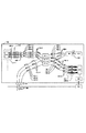
図1に、本実施例におけるOCT装置の光学系全体の概略構成について説明する図を示す。図1において、100はOCT装置、101は光源、104は出射光、105は参照光、106は測定光、142は合波された光、107は被検眼、108は戻り光、110はシングルモードファイバー、120、135はレンズ、114はミラーである。115は分散補償用ガラス、117は電動ステージ、119はXYスキャナ、125はパソコンである。
126は角膜、127は網膜、131、156は光カプラー、139はラインカメラ、140はフレームグラバー、141は透過型グレーティング、153は偏光コントローラ、155はファイバ長可変装置、157は観察カメラである。
First, the overall schematic configuration of the optical system of the OCT apparatus in the present embodiment will be described.
FIG. 1 is a diagram illustrating a schematic configuration of the entire optical system of the OCT apparatus in the present embodiment. In FIG. 1, 100 is an OCT apparatus, 101 is a light source, 104 is outgoing light, 105 is reference light, 106 is measurement light, 142 is combined light, 107 is an eye to be examined, 108 is return light, and 110 is single mode.
126 is a cornea, 127 is a retina, 131 and 156 are optical couplers, 139 is a line camera, 140 is a frame grabber, 141 is a transmission grating, 153 is a polarization controller, 155 is a fiber length variable device, and 157 is an observation camera.
本実施例のOCT装置100は、図1に示されるように、全体としてマイケルソン干渉系を構成している。
図中、光源101から出射した光である出射光104は光カプラー156にて3本の出射光104−1〜3に分割される。ここでは、1つの光源からの光を複数の光に分割して複数の出射光としたが、複数の光源を用意して、複数の出射光を構成してもよい。
さらに、出射光104−1〜3のそれぞれは、偏光コントローラ153−1を通過し、光カプラー131−1〜3にて参照光105−1〜3と測定光106−1〜3とに50:50の強度比で分割する。
測定光106−1〜3は、観察対象である被検眼107における網膜127等によって反射あるいは散乱された戻り光108−1〜3となって戻され、光カプラー131−1〜3によって、参照光105−1〜3と合波される。
参照光105−1〜3と戻り光108−1〜3とは合波された後、透過型グレーティング141によって波長毎に分光され、ラインカメラ139に入射される。ラインカメラ139は各位置(波長)毎に光強度を電圧に変換し、その信号を用いて、被検眼107の断層像が構成される。
As shown in FIG. 1, the OCT apparatus 100 of the present embodiment constitutes a Michelson interference system as a whole.
In the figure,
Further, each of the emitted lights 104-1 to 104-3 passes through the polarization controller 153-1, and the optical couplers 131-1 to 131-3 are changed to 50: Divide by 50 intensity ratios.
The measurement beams 106-1 to 106-3 are returned as return beams 108-1 to 108-3 reflected or scattered by the
After the reference beams 105-1 to 105-3 and the return beams 108-1 to 108-3 are combined, they are spectrally separated for each wavelength by the
つぎに、光源101の周辺について説明する。
光源101は代表的な低コヒーレント光源であるSLD(Super Luminescent Diode)である。
波長は830nm、バンド幅50nmである。ここで、バンド幅は、得られる断層像の光軸方向の分解能に影響するため、重要なパラメーターである。
また、光源の種類は、ここではSLDを選択したが、低コヒーレント光が出射できればよく、ASE(Amplified Spontaneous Emission)等も用いることができる。また、波長は眼を測定することを鑑みると、近赤外光が適する。
さらに、波長は、得られる断層像の横方向の分解能に影響するため、なるべく短波長であることが望ましく、ここでは830nmとする。観察対象の測定部位によっては、他の波長を選んでも良い。
Next, the periphery of the
The
The wavelength is 830 nm and the bandwidth is 50 nm. Here, the bandwidth is an important parameter because it affects the resolution in the optical axis direction of the obtained tomographic image.
Further, although the SLD is selected here as the type of light source, it is only necessary to emit low-coherent light, and ASE (Amplified Spontaneous Emission) or the like can also be used. In view of measuring the eye, near infrared light is suitable for the wavelength.
Furthermore, since the wavelength affects the resolution in the lateral direction of the obtained tomographic image, it is desirable that the wavelength be as short as possible, and here it is 830 nm. Other wavelengths may be selected depending on the measurement site to be observed.
つぎに、参照光105の光路について説明する。
光カプラー131−1〜3によって分割された参照光105−1〜3は、偏光コントローラ153−2、ファイバー長可変装置155−1〜3を通過し、レンズ135−1にて、直径1mmの平行光となって、出射される。
次に、参照光105−1〜3は分散補償用ガラス115を通過し、レンズ135−2にて、ミラー114に集光される。
次に、参照光105−1〜3はミラー114にて方向を変え、再び光カプラー131−1〜3に向かう。
次に、参照光105−1〜3は光カプラー131−1〜3を通過し、ラインカメラ139に導かれる。
ここで、分散補償用ガラス115は被検眼107を測定光106が往復した時の分散を、参照光105に対して補償するものである。
ここでは、日本人の平均的な眼球の直径として代表的な値を想定し、L=23mmとする。さらに、117−1は電動ステージであり、矢印で図示している方向に移動することができ、参照光105の光路長を、調整・制御することができる。
また、電動ステージ117−1はパソコン125により高速に制御することができる。
また、ファイバー長可変装置155−1〜3は各ファイバーの長さの微調整を行う目的で設置され、測定光106−1〜3のそれぞれの測定部位に応じて、参照光105−1〜3の光路長を調整することができ、パソコン125から制御することができる。
Next, the optical path of the reference beam 105 will be described.
The reference beams 105-1 to 105-3 divided by the optical couplers 131-1 to 131-3 pass through the polarization controller 153-2 and the fiber length variable devices 155-1 to 155-3, and are parallel with a diameter of 1 mm by the lens 135-1. It is emitted as light.
Next, the reference beams 105-1 to 105-3 pass through the
Next, the directions of the reference beams 105-1 to 105-3 are changed by the
Next, the reference beams 105-1 to 105-3 pass through the optical couplers 131-1 to 131-3 and are guided to the
Here, the
Here, a typical value is assumed as the average diameter of the Japanese eyeball, and L = 23 mm. Further, reference numeral 117-1 denotes an electric stage, which can move in the direction shown by the arrow, and can adjust and control the optical path length of the reference beam 105.
In addition, the electric stage 117-1 can be controlled by the
The fiber length variable devices 155-1 to 155-3 are installed for the purpose of finely adjusting the length of each fiber, and the reference beams 105-1 to 105-3 are selected according to the measurement sites of the measurement beams 106-1 to 106-3. Can be adjusted and can be controlled from the
つぎに、測定光106の光路について説明する。
光カプラー131−1〜3によって分割された測定光106−1〜3は、偏光コントローラ153−4を通過し、レンズ120−3にて、直径1mmの平行光となって出射され、XYスキャナ119のミラーに入射される。
ここでは、簡単のため、XYスキャナ119は一つのミラーとして記したが、実際にはXスキャン用ミラーとYスキャン用ミラーとの2枚のミラーが近接して配置され、網膜127上を光軸に垂直な方向にラスタースキャンするものである。また、測定光106−1〜3のそれぞれの中心はXYスキャナ119のミラーの回転中心と一致するようにレンズ120−1、3等が調整されている。
レンズ120−1、120−2は測定光106−1〜3が網膜127を走査するための光学系であり、測定光106を角膜126の付近を支点として、網膜127をスキャンする役割がある。
ここでは、レンズ120−1、120−2の焦点距離はそれぞれ50mm、50mmである。
また、117−2は電動ステージであり、矢印で図示している方向に移動することができ、付随するレンズ120−2の位置を、調整・制御することができる。レンズ120−2の位置を調整することで、被検眼107の網膜127の所定の層に測定光106を集光し、観察することが可能になる。
また、被検眼107が屈折異常を有している場合にも対応できる。測定光106−1〜3は被検眼107に入射すると、網膜127からの反射や散乱により戻り光108−1〜3となり、光カプラー131−1〜3を通過し、ラインカメラ139に導かれる。
ここで、電動ステージ117−2はパソコン125により高速に制御することができる。
Next, the optical path of the
The measurement beams 106-1 to 106-3 divided by the optical couplers 131-1 to 131-3 pass through the polarization controller 153-4, and are emitted as parallel light having a diameter of 1 mm by the lens 120-3, and are output by the
Here, for the sake of simplicity, the
The lenses 120-1 and 120-2 are optical systems for the measurement light 106-1 to 106-3 to scan the
Here, the focal lengths of the lenses 120-1 and 120-2 are 50 mm and 50 mm, respectively.
Reference numeral 117-2 denotes an electric stage which can move in the direction shown by the arrow, and can adjust and control the position of the associated lens 120-2. By adjusting the position of the lens 120-2, the
In addition, the case where the
Here, the electric stage 117-2 can be controlled at high speed by the
つぎに、本実施例のOCT装置における測定系の構成について説明する。
網膜127にて反射や散乱された光である戻り光108−1〜3と参照光105−1〜3とは光カプラー131−1〜3にて合波される。
そして、合波された光142は透過型グレーティング141によって波長毎に分光され、レンズ135−3で集光され、ラインカメラ139にて光の強度が各位置(波長)毎に電圧に変換される。
具体的には、ラインカメラ139上には測定光106−1〜3の数に対応して、3本の波長軸上のスペクトル領域の干渉縞が観察されることになる。
得られた電圧信号群はフレームグラバー140にてデジタル値に変換されて、パソコン125にてデータ処理を行い断層像を形成する。
ここでは、ラインカメラ139は4096画素を有し、その内3072画素を使用することで、合波された光142−1〜3のそれぞれの波長毎(1024分割)の強度を得ることができる。
Next, the configuration of the measurement system in the OCT apparatus of this embodiment will be described.
The return beams 108-1 to 108-3 and the reference beams 105-1 to 105-3, which are light reflected or scattered by the
The combined
Specifically, interference fringes in the spectral regions on the three wavelength axes are observed on the
The obtained voltage signal group is converted into a digital value by the
Here, the
つぎに、OCT装置を用いた断層像の取得方法について説明する。
ここでは、図2を用いて網膜127の断層像(光軸に平行な面)の取得方法について説明する。
図2(a)は被検眼107がOCT装置100によって観察されている様子を示している。図1に示した構成と同一または対応する構成には同一の符号が付されているから、重複する構成についての説明は省略する。
図2(a)に示すように、測定光106−1〜3は角膜126を通して、網膜127に入射すると様々な位置における反射や散乱により戻り光108−1〜3となり、それぞれの位置での時間遅延を伴って、ラインカメラ139に到達する。
Next, a method for acquiring a tomographic image using the OCT apparatus will be described.
Here, a method for acquiring a tomographic image (a plane parallel to the optical axis) of the
FIG. 2A shows a state in which the
As shown in FIG. 2 (a), when the measuring beams 106-1 to 106-3 enter the
ここでは、光源101のバンド幅が広く、空間コヒーレンス長が短いために、参照光路の光路長と測定光路の光路長とが略等しい場合に、ラインカメラ139にて、干渉縞が検出できる。上述のように、ラインカメラ139で取得されるのは波長軸上のスペクトル領域の干渉縞となる。
次に、波長軸上の情報である該干渉縞を、ラインカメラ139と透過型グレーティング141との特性を考慮して、合波された光142−1〜3毎に、光周波数軸の干渉縞に変換する。
さらに、変換された光周波数軸の干渉縞を逆フーリエ変換することで、深さ方向の情報が得られる。
Here, since the bandwidth of the
Next, considering the characteristics of the
Furthermore, information in the depth direction can be obtained by performing inverse Fourier transform on the converted interference fringes on the optical frequency axis.
さらに、簡単のため、測定光のうち106−2だけを示した図2(b)に示すように、XYスキャナ119のX軸を駆動しながら、該干渉縞を検知すれば、各X軸の位置毎に干渉縞が得られ、つまり、各X軸の位置毎の深さ方向の情報を得ることができる。
結果として、XZ面での戻り光108−2の強度の2次元分布が得られ、それはすなわち断層像132である(図2(c))。
本来は、断層像132は上記説明したように、該戻り光108の強度をアレイ状に並べたものであり、例えば該強度をグレースケールに当てはめて、表示されるものである。ここでは得られた断層像の境界のみ強調して表示している。
Further, for the sake of simplicity, as shown in FIG. 2B showing only 106-2 of the measurement light, if the interference fringes are detected while driving the X axis of the
As a result, a two-dimensional distribution of the intensity of the return light 108-2 on the XZ plane is obtained, that is, a tomographic image 132 (FIG. 2C).
Originally, as described above, the
また、図2(d)に示す様に、XYスキャナ119を制御して、測定光106−1〜3を網膜127上にラスタースキャンすれば、3つの断層像を同時に、連続して取得することができる。ここでは、XYスキャナの主走査方向をX軸方向、副走査方法をY軸方向として、スキャンする場合を示し、結果として複数のYZ面の断層像を得ることができる。また、ここでは、測定光106−1〜3のそれぞれが、お互いの重複なくスキャンする場合を示しているが、断層像のレジストレーション等のため、重複してスキャンしてもよい。
Also, as shown in FIG. 2D, if the
つぎに、本発明の特徴である測定光観察系の構成について図1を用いて説明する。
OCT装置100において、測定光106−1〜3は上記説明したように、角膜126を通して、網膜127に照射される。観察カメラ157は測定光106−1〜3が角膜126を通して、網膜127に入射する様子を観察する目的で設置されている。
ここでは、被検眼107の右側前方に設置されているが、角膜126付近を観察出来れば、観察カメラ157の位置は何処であってもよい。
また、前記観察手段により取得された観察画像によって、前記測定光群と前記被検眼との相対位置を調整可能に構成された調整手段をつぎのように構成することができる。
例えば、観察カメラ157とパソコン125とを電気的に接続して、観察カメラ157で取得した観察像をパソコン125に取り込み、画像処理等を施し、OCT装置100と被検眼107との相対位置の調整に用いることができる。
また、観察像とOCT像とを関連づけて、表示や保存等を行うことができる。観察カメラ157は測定光106の波長830nmに対応して、ここでは近赤外カメラを用いる。また、近赤外カメラを近赤外のエリアセンサとレンズを組み合わせて構成してもよい。
Next, the configuration of the measurement light observation system, which is a feature of the present invention, will be described with reference to FIG.
In the OCT apparatus 100, the measuring beams 106-1 to 106-3 are irradiated to the
Here, it is installed in front of the right side of the
In addition, the adjusting means configured to be able to adjust the relative position between the measurement light group and the eye to be inspected based on the observation image acquired by the observation means can be configured as follows.
For example, the
Further, the observation image and the OCT image can be associated with each other and displayed or stored. The
次に、観察カメラ157を用いて取得される観察像142について図3から図6を用いて説明する。
図1、図2に示した構成と同一または対応する構成には同一の符号が付されているから、重複する構成についての説明は省略する。
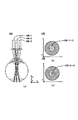
図3(a)は観察対象である被検眼107の断面を模式的に表す模式図143である。
ここで、158は瞳孔、159は虹彩、160は水晶体である。図3(b)は観察像142である。
ここでは、測定光106−1〜3が被検眼107に対して、適切に照射されている様子を示している。
具体的には、適切な照射とは、測定光106−1〜3が虹彩159にけられることなく瞳孔158を通過し、水晶体160の表面付近で交差するように、被検眼107とOCT装置100との相対位置が調整されていることである。
測定光106の光路として、瞳孔158が最も狭くなるため、上記したように調整すると、より太い測定光106を被検眼107に入射することが可能になり、OCT装置の高解像度化に有利である。
図3(b)は水晶体160の表面付近に焦点を合わせて、測定光106−1〜3の様子を観察する観察像142である。
ここでは、測定光106−1〜3が略同一の位置を通過しているため、見かけ上、測定光106−1〜3は一つの円として認識できる。
ここで、水晶体160の表面とレンズ120−2との距離は、レンズ120−2の焦点距離と同一の50mmとし、XYスキャナ119のミラー面と水晶体160の表面とが光学的に共役な関係となっている。
Next, the
Since the same or corresponding components as those shown in FIGS. 1 and 2 are denoted by the same reference numerals, the description of the overlapping components is omitted.
FIG. 3A is a schematic diagram 143 schematically illustrating a cross section of the
Here, 158 is a pupil, 159 is an iris, and 160 is a crystalline lens. FIG. 3B is an
Here, a state in which the measuring beams 106-1 to 106-3 are appropriately irradiated to the
Specifically, the appropriate irradiation means that the measurement light 106-1 to 103-1 passes through the
Since the
FIG. 3B is an
Here, since the measuring beams 106-1 to 106-3 pass through substantially the same position, the measuring beams 106-1 to 106-3 can be recognized as one circle.
Here, the distance between the surface of the
つぎに、被検眼107とOCT装置100との相対位置が適切でない場合について説明する。
図4(a)、図4(b)は被検眼107とOCT装置100との相対位置が図3(a)に示した最適位置と比較して近接している場合を示している。
その場合には、図4(a)から把握できるように、図4(b)のように、測定光106−1〜3が見かけ上広がって観察できる。
ここで、測定光106−1を遮蔽して、図4(c)のような観察像142を取得すれば、測定光106−2〜3が、遮蔽前と比較して+X側に観察でき、被検眼107とOCT装置100との相対位置が最適位置と比較して近接していることが把握できる。
Next, a case where the relative position between the
FIGS. 4A and 4B show a case where the relative position between the
In that case, as can be grasped from FIG. 4A, the measurement beams 106-1 to 106-3 can be apparently spread and observed as shown in FIG. 4B.
Here, if the measurement light 106-1 is shielded and an
また、図5(a)に示すように、被検眼107とOCT装置100との相対位置が図3(a)に示した最適位置と比較して、離れている場合には、図5(b)示すような観察像142を取得することができる。
同様に、測定光106−1を遮蔽して、図5(c)のような観察像142を取得すれば、測定光106−2〜3が−X側に観察でき、被検眼107とOCT装置100との相対位置が最適位置と比較して離れていることが把握できる。
さらに、図6(a)に示すように、被検眼107がOCT装置100に対して、−X方向にずれている場合には、図6(b)示すような観察像142を取得することができ、その状況は明らかである。
Further, as shown in FIG. 5A, when the relative position between the
Similarly, if the measurement light 106-1 is shielded and an
Further, as shown in FIG. 6A, when the
上記したような、被検眼107とOCT装置100との相対位置が適切でない場合には、上記説明した、XYスキャナ119のミラー面と水晶体160の表面との光学的に共役な関係が成り立たないことになる。
そのため、図4(a)、図5(a)、図6(a)に代表される状態は、図3(a)の状態に比べて、戻り光108−1〜3の強度が小さくなり、結果として断層像を構成するための後述する干渉信号のS/N比が低くなる。
一般に、網膜に照射できる測定光のエネルギーには上限がある。そのため、診断に適する断層像を取得するには、測定光106を瞳孔158に適切に入射することが重要になる。また、被検者の静止が難しい等の理由から、測定光106−1〜3がやむを得ず虹彩159に照射された場合であっても、観察像142は、取得した断層像の信頼性の評価を行う手段として用いることができる。
When the relative position between the
Therefore, in the states represented by FIGS. 4A, 5A, and 6A, the intensity of the return lights 108-1 to 108-3 is smaller than the state of FIG. As a result, the S / N ratio of an interference signal to be described later for forming a tomographic image is lowered.
In general, there is an upper limit to the energy of measurement light that can be irradiated on the retina. Therefore, in order to acquire a tomographic image suitable for diagnosis, it is important that the
つぎに、本発明の特徴である被検眼の位置を調整して光断層画像を撮像する光断層画像の撮像方法について具体的に主に図7を用いて説明する。
図1〜6に示した構成と同一または対応する構成には同一の符号が付されているから、重複する構成についての説明は省略する。
一般に眼底の網膜を観察する場合には、安全上の問題から、測定光を網膜上に走査して行う。
本実施例における光断層画像の撮像方法は、測定光を網膜上に走査しながら行うが、適宜、走査範囲を調整してもよい。
この光断層画像の撮像方法においては、以下の(1)〜(4)の工程を、例えば連続して行うものである。或いは、適宜工程を戻って行うこともできる。
また、コンピュータ等を用いて、以下の工程を自動的に行うように構成してもよい。
図8に、上記光断層画像の撮像方法を説明するための各工程のフロー図を示す。
(1)被検者の被検眼107を所定の位置に誘導し、観察カメラ157(図1参照)を用いて水晶体160の表面付近を観察し、観察像142を得る。ここでは、測定光の走査範囲を小さめに設定するとよい(図7(a))。
(2)測定光106−1を一旦、遮光して観察像142を得る(図7(b))。観察像142から、測定光106−2〜3が−X側に観察でき、被検眼107の位置は図7(c)の様であると推測できる。また、パソコン125を用いて、観察像142に画像処理を施し、測定光106の大きさを定量化してもよい。
(3)顔受けユニットや固視灯等(共に不図示)を用いて、被検眼107を+X方向、+Z方向に誘導する。適宜、観察像142を注視し、測定光106−1〜3が見かけ上最小、また瞳孔158の中心に来るように誘導、調整する。(図7(d))。
(4)測定光の走査範囲を所定の範囲に設定する。レンズ120−2の位置を調整することで視度補正を行い、断層像が鮮明になるように、調整する。
Next, an optical tomographic image capturing method for capturing an optical tomographic image by adjusting the position of the eye to be examined, which is a feature of the present invention, will be specifically described mainly with reference to FIG.
Since the same or corresponding components as those shown in FIGS. 1 to 6 are denoted by the same reference numerals, the description of the overlapping components is omitted.
In general, when the retina of the fundus is observed, the measurement light is scanned on the retina for safety reasons.
Although the optical tomographic image capturing method in the present embodiment is performed while scanning the measurement light on the retina, the scanning range may be adjusted as appropriate.
In this optical tomographic image capturing method, the following steps (1) to (4) are performed, for example, continuously. Alternatively, the process can be performed by returning appropriately.
Moreover, you may comprise so that the following processes may be performed automatically using a computer etc.
FIG. 8 shows a flowchart of each step for explaining the above-described optical tomographic image capturing method.
(1) The examinee's
(2) The measurement light 106-1 is once shielded to obtain an observation image 142 (FIG. 7B). From the
(3) The
(4) The scanning range of the measurement light is set to a predetermined range. Diopter correction is performed by adjusting the position of the lens 120-2 so that the tomographic image becomes clear.
[実施例2]
実施例2においては、本発明を適用した、OCT装置について説明する。
ここでは特に、被検眼の断層画像(OCT像)及び眼底画像(平面像)を撮像する装置について説明する。
本実施例においては、眼底カメラにアダプターを介してOCT撮像部を接続してなるOCT装置について説明する。
本実施例は、スペースの利用効率が高く、採算性の高いOCT装置となっている。ここで説明するOCT装置は実施例1と同様に、フーリエドメイン方式のOCT装置であり、さらに、高速撮像を目的として3本の測定光を有し、同時に3つの断層像の取得が可能な、マルチビームのOCT装置である。
[Example 2]
In the second embodiment, an OCT apparatus to which the present invention is applied will be described.
Here, an apparatus that captures tomographic images (OCT images) and fundus images (planar images) of the eye to be examined will be described in particular.
In this embodiment, an OCT apparatus in which an OCT imaging unit is connected to a fundus camera via an adapter will be described.
This embodiment is an OCT apparatus with high space utilization efficiency and high profitability. The OCT apparatus described here is a Fourier domain type OCT apparatus as in the first embodiment, and further has three measurement beams for the purpose of high-speed imaging, and can simultaneously acquire three tomographic images. This is a multi-beam OCT apparatus.
本実施例におけるアダプターを含んだOCT装置の全体の構成について図9を用いて説明する。図9はOCT装置の側面図であり、200はOCT装置、102はOCT撮像部、300は眼底カメラ本体部、400はアダプター、500はカメラ部である。
ここで、眼底カメラ本体部300とアダプター400とカメラ部500とは光学的に接続されている。
ここで、眼底カメラ本体部300とアダプター400とは相対的に移動可能に保持されている。
そのため、大まかな光学的調整を行うことができる。また、アダプター400とOCT撮像部102とは3本のシングルモードファイバー148を介して光学的に接続されている。アダプター400とOCT撮像部102とは3つづつのコネクター410とコネクター154とをそれぞれ有している。そのため、簡単に取り付け及び取り外しが可能である。
また、323は顔受けユニットであり、被検者のあごと額とを固定することで、被検眼の固定を促し、撮像を行う。
また、125はパソコンであり、断層画像の構成や表示等を行う。
ここで、カメラ部500は汎用のデジタル一眼レフカメラである。カメラ部500とアダプター400あるいは眼底カメラ本体部300とは汎用のカメラマウントで接続される。
The overall configuration of the OCT apparatus including the adapter in this embodiment will be described with reference to FIG. FIG. 9 is a side view of the OCT apparatus, in which 200 is an OCT apparatus, 102 is an OCT imaging unit, 300 is a fundus camera body, 400 is an adapter, and 500 is a camera unit.
Here, the fundus camera
Here, the fundus camera
Therefore, rough optical adjustment can be performed. Further, the
Here, the
本実施例におけるアダプターを含んだOCT装置の光学系の構成について図10を用いて、説明する。
図10において、200はOCT装置、107は被検眼、300は眼底カメラ本体部、400はアダプター、500はカメラ部、102はOCT撮像部である。OCT装置200は、OCT撮像部102とカメラ部500とを用いて被検眼107の網膜127の断層画像(OCT像)及び眼底画像(平面像)を取得することを目的としている。
The configuration of the optical system of the OCT apparatus including the adapter in this embodiment will be described with reference to FIG.
In FIG. 10, 200 is an OCT apparatus, 107 is an eye to be examined, 300 is a fundus camera main body, 400 is an adapter, 500 is a camera unit, and 102 is an OCT imaging unit. The
まず、眼底カメラ本体部300について説明する。
被検眼107に対向して、対物レンズ302が設置され、その光軸上で孔あきミラー303によって光路351と光路352とに分岐される。
光路352は被検眼107の眼底を照明する照明光学系を形成している。眼底カメラ本体部300の下部には、被検眼107の位置合わせに用いられるハロゲンランプ316、被検眼107の眼底の撮像に用いるストロボ管314が設置されている。
ここで、313、315はコンデンサレンズ、317はミラーである。ハロゲンランプ316とストロボ管314とからの照明光はリングスリット312によってリング状の光束となり、孔あきミラー303によって反射され、被検眼107の眼底を照明する。
ここで、309、311はレンズ、310は光学フィルターである。
First, the fundus camera
An
The
Here, 313 and 315 are condenser lenses, and 317 is a mirror. Illumination light from the
Here,
光路351は被検眼107の眼底の断層画像及び眼底画像を撮像する撮像光学系を形成している。孔あきミラー303の右方にはフォーカスレンズ304と結像レンズ305が設置されている。
ここで、フォーカスレンズ304は光軸方向に移動可能に支持され、パソコン125によってその位置を制御できる。次に、クイックリターンミラー318を介して、光路351は固視灯320及び観察カメラ321に導かれている。
ここで、クイックリターンミラー318は赤外光の一部を反射及び透過し、可視光を反射するように設計されている。赤外光の一部を反射及び透過するよう設計しているため、固視灯320と観察カメラ321とOCT撮像部102とを同時に使用することが可能になっている。
また、319はダイクロイックミラーであり、固視灯320方向に可視光が、観察カメラ321方向に赤外光がそれぞれ分岐されるよう設計されている。
次に、光路351はミラー306、フィールドレンズ322、ミラー307、リレーレンズ308を介して、アダプター400に導かれる。
ここで、観察カメラ321は角膜126付近を観察し、測定光106−1〜3が被検眼107に入射する様子を把握することができ、本発明の特徴としている。また、固視灯320を用いて、被検眼127を誘導することができる。
The optical path 351 forms an imaging optical system that captures a tomographic image and a fundus image of the fundus of the
Here, the
Here, the
Next, the optical path 351 is guided to the
Here, the
つぎに、光学系の構成(アダプター、カメラ部)について説明する。
アダプター400は光路351をダイクロイックミラー405を介して、断層画像撮像用の光路351−1と眼底画像撮像用の光路351−2とに分割することを最大の機能としている。
ここで、406、407はリレーレンズ、408はXYスキャナ、409はコリメートレンズである。
また、ここでは、リレーレンズ406、407は移動可能に保持され、細かな位置調整を行うことで、光路351−1と351−2との光軸を調整することができる。
なお、ここでは、簡単のため、XYスキャナ408は一つのミラーとして記したが、実際にはXスキャン用ミラーとYスキャン用ミラーとの2枚のミラーが近接して配置され、網膜127上を光軸に垂直な方向にラスタースキャンするものである。
また、XYスキャナ408はパソコン125によって制御される。
また、光路351−1の光軸はXYスキャナ408の2つのミラーの回転中心と一致するように調整されている。
また、410は3本の光ファイバーを取り付けるための3個のコネクターであり、3本の測定光をOCT撮像部102からアダプター400と眼底カメラ本体部300と被検眼107に順に入射することができる。
カメラ部500は眼底画像を撮像するためのデジタル一眼レフカメラである。アダプター400とカメラ部500とは汎用のカメラマウントを介して接続される。
そのため、容易に着脱が可能である。501はエリアセンサであり、その表面に眼底像が形成される。
Next, the configuration of the optical system (adapter, camera unit) will be described.
The
Here, 406 and 407 are relay lenses, 408 is an XY scanner, and 409 is a collimating lens.
Further, here, the relay lenses 406 and 407 are held so as to be movable, and the optical axes of the optical paths 351-1 and 351-2 can be adjusted by performing fine position adjustment.
Here, for the sake of simplicity, the
The
The optical axis of the optical path 351-1 is adjusted so as to coincide with the rotation center of the two mirrors of the
The
Therefore, it can be easily attached and detached.
つぎに、光学系の構成(OCT部)について説明する。
本実施例においては、OCT撮像部102は、光学系の一部を光ファイバーを用いて、構成することにより、装置の小型化が図られている。
測定光学系が眼底カメラ本体部300からなることを除けば、実施例1と同一である。
実施例1の図1に示した構成と同一または対応する構成には同一の符号が付されているから、重複する構成についての説明は省略する。
Next, the configuration of the optical system (OCT unit) will be described.
In the present embodiment, the
Except that the measurement optical system is composed of the fundus camera
Since the same or corresponding components as those shown in FIG. 1 of the first embodiment are denoted by the same reference numerals, the description of the overlapping components is omitted.
まず、本実施例におけるOCT撮像部102の光学系の全体の概略構成について説明する。
図11に、本実施例におけるOCT装置の光学系全体の概略構成について説明する図を示す。
図11において、102はOCT撮像部、101は光源、104は出射光、105は参照光、106は測定光、142は合波された光、110、148はシングルモードファイバー、135はレンズ、114はミラーである。
115は分散補償用ガラス、117は電動ステージ、125はパソコンである。131、156は光カプラー、139はラインカメラ、140はフレームグラバー、141は透過型グレーティング、153は偏光コントローラ、155はファイバ長可変装置である。
First, the overall schematic configuration of the optical system of the
FIG. 11 illustrates a schematic configuration of the entire optical system of the OCT apparatus according to the present embodiment.
In FIG. 11, 102 is an OCT imaging unit, 101 is a light source, 104 is outgoing light, 105 is reference light, 106 is measurement light, 142 is combined light, 110 and 148 are single mode fibers, 135 is a lens, 114 Is a mirror.
115 is a glass for dispersion compensation, 117 is an electric stage, and 125 is a personal computer. 131 and 156 are optical couplers, 139 is a line camera, 140 is a frame grabber, 141 is a transmissive grating, 153 is a polarization controller, and 155 is a fiber length variable device.
本実施例のOCT装置100は、図11に示されるように、全体としてマイケルソン干渉系を構成している。
図中、光源101から出射した光である出射光104は光カプラー156にて3本の出射光104−1〜3に分割される。
さらに、出射光104−1〜3のそれぞれは、偏光コントローラ153−1を通過し、光カプラー131−1〜3にて参照光105−1〜3と測定光106−1〜3を50:50の強度比で分割する。
測定光106−1〜3は、コネクター154、アダプター400、眼底カメラ本体部300を介して、観察対象である被検眼107における網膜127等によって反射あるいは散乱された戻り光108−1〜3となって戻される。そして、光カプラー131−1〜3によって、参照光105−1〜3と合波される(図10)。
参照光105−1〜3と戻り光108−1〜3とは合波された後、透過型グレーティング141によって波長毎に分光され、ラインカメラ139に入射される。ラインカメラ139は各位置(波長)毎に光強度を電圧に変換し、その信号を用いて、被検眼107の断層像が構成される。
As shown in FIG. 11, the OCT apparatus 100 of the present embodiment constitutes a Michelson interference system as a whole.
In the figure,
Further, each of the outgoing lights 104-1 to 104-3 passes through the polarization controller 153-1, and the optical couplers 131-1 to 131-3 convert the reference lights 105-1 to 105-1 and the measuring lights 106-1 to 50-3 by 50:50. Divide by intensity ratio.
The measurement lights 106-1 to 106-3 are returned light 108-1 to 108-3 reflected or scattered by the
After the reference beams 105-1 to 105-3 and the return beams 108-1 to 108-3 are combined, they are spectrally separated for each wavelength by the
つぎに、光源101の周辺について説明する。
光源101は代表的な低コヒーレント光源であるSLD(Super Luminescent Diode)である。波長は830nm、バンド幅50nmである。
ここで、バンド幅は、得られる断層像の光軸方向の分解能に影響するため、重要なパラメーターである。
また、光源の種類は、ここではSLDを選択したが、低コヒーレント光が出射できればよく、ASE(Amplified Spontaneous Emission)等も用いることができる。
また、波長は眼を測定することを鑑みると、近赤外光が適する。さらに波長は、得られる断層像の横方向の分解能に影響するため、なるべく短波長であることが望ましく、ここでは830nmとする。観察対象の測定部位によっては、他の波長を選んでも良い。
Next, the periphery of the
The
Here, the bandwidth is an important parameter because it affects the resolution in the optical axis direction of the obtained tomographic image.
Further, although the SLD is selected here as the type of light source, it is only necessary to emit low-coherent light, and ASE (Amplified Spontaneous Emission) or the like can also be used.
In view of measuring the eye, near infrared light is suitable for the wavelength. Further, since the wavelength affects the resolution in the lateral direction of the obtained tomographic image, it is desirable that the wavelength is as short as possible, and here it is 830 nm. Other wavelengths may be selected depending on the measurement site to be observed.
つぎに、参照光105の光路について説明する。
光カプラー131−1〜3によって分割された参照光105−1〜3は偏光コントローラ153−2、ファイバー長可変装置155−1〜3を通過し、レンズ135−1にて、直径1mmの平行光となって、出射される。
次に、参照光105−1〜3は分散補償用ガラス115を通過し、レンズ135−2にて、ミラー114に集光される。
次に、参照光105−1〜3はミラー114にて方向を変え、再び光カプラー131−1〜3に向かう。
次に、参照光105−1〜3は光カプラー131−1〜3を通過し、ラインカメラ139に導かれる。
分散補償用ガラス115は被検眼107を測定光106が往復した時の分散を、参照光105に対して補償するものである。
ここでは、日本人の平均的な眼球の直径として代表的な値を想定し、L=23mmとする。さらに、117−1は電動ステージであり、矢印で図示している方向に移動することができ、参照光105の光路長を、調整・制御することができる。
また、電動ステージ117−1はパソコン125により高速に制御することができる。
また、ファイバー長可変装置155−1〜3は各ファイバーの長さの微調整を行う目的で設置され、測定光106−1〜3のそれぞれの測定部位に応じて、参照光105−1〜3の光路長を調整することができ、パソコン125から制御することができる。
Next, the optical path of the reference beam 105 will be described.
The reference beams 105-1 to 105-3 divided by the optical couplers 131-1 to 131-3 pass through the polarization controller 153-2 and the fiber length variable devices 155-1 to 155-3, and are parallel light having a diameter of 1 mm by the lens 135-1. And emitted.
Next, the reference beams 105-1 to 105-3 pass through the
Next, the directions of the reference beams 105-1 to 105-3 are changed by the
Next, the reference beams 105-1 to 105-3 pass through the optical couplers 131-1 to 131-3 and are guided to the
The
Here, a typical value is assumed as the average diameter of the Japanese eyeball, and L = 23 mm. Further, reference numeral 117-1 denotes an electric stage, which can move in the direction shown by the arrow, and can adjust and control the optical path length of the reference beam 105.
In addition, the electric stage 117-1 can be controlled by the
The fiber length variable devices 155-1 to 155-3 are installed for the purpose of finely adjusting the length of each fiber, and the reference beams 105-1 to 105-3 are selected according to the measurement sites of the measurement beams 106-1 to 106-3. Can be adjusted and can be controlled from the
つぎに、測定光106の光路について説明する。
光カプラー131−1〜3によって分割された測定光106−1〜3は、偏光コントローラ153−4を通過する。そして、コネクター154、シングルモードファイバー148、アダプター400、眼底カメラ本体部300を介して、測定光106−1〜3は被検眼107の網膜に導かれる(図10)。
測定光106−1〜3が被検眼107に入射すると、網膜127からの反射や散乱により戻り光108−1〜3となる。
戻り光108−1〜3は、再び、眼底カメラ本体部300、アダプター400、コネクター410、シングルモードファイバー148、コネクター154を順に介して、光カプラー131−1〜3に導かれる。
前述の参照光105−1〜3と戻り光108−1〜3とは、光カプラー131−1〜3にて合波され、さらに50:50に分割される。
そして、合波された光142−1〜3は透過型グレーティング141によって波長毎に分光され、レンズ135−3で集光され、ラインカメラ139にて光の強度が各位置(波長)毎に電圧に変換される。
具体的には、ラインカメラ139上には波長軸上のスペクトル領域の干渉縞が観察されることになる。
Next, the optical path of the
The measuring beams 106-1 to 106-3 divided by the optical couplers 131-1 to 131-3 pass through the polarization controller 153-4. Then, the measuring beams 106-1 to 106-3 are guided to the retina of the
When the measuring beams 106-1 to 106-3 are incident on the
The return lights 108-1 to 108-3 are again guided to the optical couplers 131-1 to 131-3 through the fundus camera
The reference beams 105-1 to 105-3 and the return beams 108-1 to 108-3 are combined by the optical couplers 131-1 to 131-3 and further divided into 50:50.
Then, the combined light 142-1 to 142-3 are separated by wavelength by the transmission grating 141, condensed by the lens 135-3, and the intensity of the light is applied to the voltage at each position (wavelength) by the
Specifically, interference fringes in the spectral region on the wavelength axis are observed on the
つぎに、本実施例のOCT装置における測定系の構成について説明する。
OCT撮像系102は、マイケルソン干渉系による干渉信号の強度から構成される断層像(OCT像)を取得することができる。
その測定系について、更に説明すると、網膜127にて反射や散乱された光である戻り光108−1〜3と参照光105−1〜3とは光カプラー131−1〜3にて合波される。
そして、合波された光142は透過型グレーティング141によって波長毎に分光され、レンズ135−3で集光され、ラインカメラ139にて光の強度が各位置(波長)毎に電圧に変換される。
具体的には、ラインカメラ139上には測定光106−1〜3の数に対応して、3本の波長軸上のスペクトル領域の干渉縞が観察されることになる。
得られた電圧信号群はフレームグラバー140にてデジタル値に変換されて、パソコン125にてデータ処理を行い断層像を形成する。
ここでは、ラインカメラ139は4096画素を有し、その内3072画素を使用することで、合波された光142−1〜3のそれぞれの波長毎(1024分割)の強度を得ることができる。
Next, the configuration of the measurement system in the OCT apparatus of this embodiment will be described.
The
The measurement system will be further described. The return beams 108-1 to 108-3 and the reference beams 105-1 to 105-3, which are reflected or scattered by the
The combined
Specifically, interference fringes in the spectral regions on the three wavelength axes are observed on the
The obtained voltage signal group is converted into a digital value by the
Here, the
つぎに、断層像の取得方法について説明する。
OCT装置を用いた断層像の取得方法は実施例1と略同一であるため説明を省略する。
OCT装置200は、XYスキャナ408を制御し、ラインカメラ139で干渉縞を取得することで、網膜127の断層像を取得することができる(図10)。
Next, a method for acquiring a tomographic image will be described.
Since the tomographic image acquisition method using the OCT apparatus is substantially the same as that of the first embodiment, the description thereof is omitted.
The
つぎに、測定光観察系の構成について説明する。
本発明の特徴である測定光観察系の構成については、観察カメラ321が眼底カメラ本体部300の内部に設置されていることを除けば、実施例1と略同一であるため重複する説明は省略する。
OCT装置200は、眼底カメラ本体部300の内部に設置されている観察カメラ321を用いて、測定光106−1〜3が角膜126付近を観察し、OCT装置200と被検眼107の相対位置の調整に用いることができる。
また、調整には固視灯320、顔受けユニット323、パソコン125等を用いることができる。
Next, the configuration of the measurement light observation system will be described.
The configuration of the measurement light observation system, which is a feature of the present invention, is substantially the same as that of the first embodiment except that the
The
Further, a
100:OCT装置
101:光源
102:OCT撮像部
105:参照光
106:測定光
107:被検眼
108:戻り光
114、306、307、317:ミラー
115:分散補償用ガラス
117:電動ステージ
119、408:XYスキャナ
125:パソコン
126:角膜
127:網膜
110、148:シングルモードファイバー
131、156:光カプラー
132:断層像
120、135、309、311:レンズ
139:ラインカメラ
140:フレームグラバー
141:透過型グレーティング
142:合波された光
153:偏光コントローラ
154、410:コネクター
155:ファイバー長可変装置
157、321:観察カメラ
158:瞳孔
159:虹彩
160:水晶体
200:OCT装置
300:眼底カメラ本体部
302:対物レンズ
303:孔あきミラー
304:フォーカスレンズ
305:結像レンズ
308、406、407:リレーレンズ
310:光学フィルター
312:リングスリット
313、315:コンデンサレンズ
314:ストロボ管
316:ハロゲンランプ
318:クイックリターンミラー
319、405:ダイクロイックミラー
320:固視灯
322:フィールドレンズ
323:顔受けユニット
351、352:光路
400:アダプター
409:コリメートレンズ
500:カメラ部
100: OCT apparatus 101: Light source 102: OCT imaging unit 105: Reference light 106: Measurement light 107: Eye 108: Return light 114, 306, 307, 317: Mirror 115: Dispersion compensation glass 117:
Claims (21)
前記複数の測定光を前記被検眼の前眼部に照射する照射手段と、
前記照射手段により前記前眼部に照射されている前記複数の測定光の照射領域の情報を取得する取得手段と、
前記取得された照射領域の情報に基づいて、前記複数の測定光の照射領域が所定の重複状態になるように、前記照射手段と前記前眼部との距離を調整する調整手段と、
を有することを特徴とする光断層撮像装置。 A plurality of return light from the eye irradiated a plurality of measurement light based on the plurality of light and a plurality of reference beams that correspond to the plurality of measurement light and if wave, the該被fundus tomographic image an optical cross layer imaging device for acquiring,
Irradiating means for irradiating the anterior eye part of the eye to be examined with the plurality of measurement lights;
An acquisition means for acquiring information of an irradiation area of the plurality of measurement lights irradiated to the anterior eye portion by the irradiation means;
Based on the information of the obtained irradiation area, and adjusting means irradiation area of the plurality of measurement light to a predetermined overlapping state, to adjust the distance between the irradiation unit and the anterior segment,
Light sectional layer imaging device characterized in that it comprises a.
前記調整手段が、前記重複面積が大きくなるように、前記照射手段と前記前眼部との距離を調整することを特徴とする請求項1または2に記載の光断層撮像装置。
The information of the irradiation region is an overlapping area of the irradiation regions of the plurality of measurement lights,
The adjusting means such that said overlap area is increased, the optical cross layer imaging device according to claim 1 or 2, characterized in that adjusting the distance between the anterior segment and the irradiation unit.
前記調整手段が、前記略中心同士の距離が小さくなるように、前記照射手段と前記前眼部との距離を調整することを特徴とする請求項1または2に記載の光断層撮像装置。 The information of the irradiation area is a distance between the approximate centers of the irradiation areas of the plurality of measurement lights,
The adjusting means such that said distance between the substantially center becomes smaller, the light sectional layer imaging device according to claim 1 or 2, characterized in that adjusting the distance between the irradiation unit and the anterior segment .
前記調整された後、前記共通の走査手段と前記前眼部とが光学的に略共役な関係であることを特徴とする請求項1乃至4のいずれか1項に記載の光断層撮像装置。5. The optical tomographic imaging apparatus according to claim 1, wherein after the adjustment, the common scanning unit and the anterior eye part are in an optically conjugate relationship. 6.
乃至5のいずれか1項に記載の光断層撮像装置。6. The optical tomographic imaging apparatus according to any one of items 1 to 5.
前記単一の光源が発生した光から分割された複数の光を前記複数の測定光と前記複数の参照光とに分割する分割部材と、A dividing member that divides a plurality of lights divided from the light generated by the single light source into the plurality of measurement lights and the plurality of reference lights;
を更に有することを特徴とする請求項1乃至7のいずれか1項に記載の光断層撮像装置。The optical tomographic imaging apparatus according to claim 1, further comprising:
前記被検眼の前眼部の観察画像を取得する観察画像取得手段と、
前記観察画像と前記断層画像とを関連付けて記録する記録手段と、を有し、
前記観察画像を解析することにより、前記照射領域の情報を取得することを特徴とする請求項1から8のいずれか1項に記載の光断層撮像装置。 The acquisition means is
An observation image acquisition means for acquiring an observation image of the anterior segment of the eye to be examined;
Recording means for associating and recording the observation image and the tomographic image,
Wherein by the observed image analyzing, optical cross layer imaging device according to any one of claims 1 8, characterized in that to obtain the information of the irradiation region.
前記被検眼の眼底の平面像を撮像するカメラ部と、
を有することを特徴とする請求項1から12のいずれか1項に記載の光断層撮像装置。 A fundus camera main body portion of the optical cross layer imaging device for imaging a tomographic image of the fundus oculi of the eye to be examined,
A camera unit that captures a planar image of the fundus of the eye to be examined;
Light sectional layer imaging device according to claim 1, any one of 12, characterized in that it comprises a.
前記複数の測定光の数を増減可能に構成、
前記複数の測定光の走査範囲を増減可能に構成、
前記被検眼に注視させる固視灯によって視線を移動可能に構成、
被検者の顔を所定の位置に保持する顔受けユニットを移動可能に構成、
前記複数の測定光を前記被検眼に導く測定光学系を調整可能に構成、
のいずれかに可能に構成されていることを特徴とする請求項1から13のいずれか1項に記載の光断層撮像装置。 The adjusting means is
A configuration capable of increasing or decreasing the number of the plurality of measurement lights;
A configuration capable of increasing or decreasing the scanning range of the plurality of measurement lights,
A structure in which the line of sight can be moved by a fixation lamp to be gazed at the eye to be examined,
A face receiving unit that holds the face of the subject in a predetermined position is configured to be movable,
A configuration capable of adjusting a measurement optical system that guides the plurality of measurement lights to the eye to be examined;
Light sectional layer imaging device according to any one of claims 1 to 13, characterized that you have been configured to be in either.
前記複数の測定光を前記被検眼の前眼部に照射する照射手段により前記前眼部に照射されている前記複数の測定光の照射領域の情報を取得する工程と、
前記取得された照射領域の情報に基づいて、前記複数の測定光の照射領域が所定の重複状態になるように、前記照射手段と前記前眼部との距離を調整する工程と、
を有することを特徴とする光断層撮像装置の制御方法。 A plurality of return light from the eye irradiated a plurality of measurement light based on the plurality of light and a plurality of reference beams that correspond to the plurality of measurement light and if wave, the該被fundus tomographic image a control method for an optical cross-sectional layer imaging device for acquiring,
Obtaining information on an irradiation area of the plurality of measurement lights irradiated to the anterior eye by an irradiation unit that irradiates the anterior eye of the eye to be examined with the plurality of measurement lights;
Based on the information of the obtained irradiation region, so that the irradiation area of the plurality of measurement light becomes a predetermined overlapping state, and adjusting the distance between the irradiation unit and the anterior segment,
Method of controlling an optical cross-sectional layer imaging device characterized in that it comprises a.
前記調整する工程において、前記重複面積が大きくなるように、前記照射手段と前記前眼部との距離を調整することを特徴とする請求項15または16に記載の光断層撮像装置の制御方法。The method of controlling an optical tomographic imaging apparatus according to claim 15 or 16, wherein, in the adjusting step, a distance between the irradiation unit and the anterior segment is adjusted so that the overlapping area is increased.
前記調整する工程において、前記略中心同士の距離が小さくなるように、前記照射手段と前記前眼部との距離を調整することを特徴とする請求項15または16に記載の光断層撮像装置の制御方法。The optical tomographic imaging apparatus according to claim 15 or 16, wherein, in the adjusting step, a distance between the irradiation unit and the anterior eye part is adjusted so that a distance between the substantially centers becomes small. Control method.
前記調整された後、前記共通の走査手段と前記前眼部とが光学的に略共役な関係であることを特徴とする請求項15乃至18のいずれか1項に記載の光断層撮像装置の制御方法。19. The optical tomographic imaging apparatus according to claim 15, wherein after the adjustment, the common scanning unit and the anterior ocular segment have an optically substantially conjugate relationship. Control method.
Priority Applications (5)
| Application Number | Priority Date | Filing Date | Title |
|---|---|---|---|
| JP2008331925A JP5455001B2 (en) | 2008-12-26 | 2008-12-26 | Optical tomographic imaging apparatus and control method for optical tomographic imaging apparatus |
| PCT/JP2009/071718 WO2010074279A1 (en) | 2008-12-26 | 2009-12-18 | Optical tomographic imaging apparatus and imaging method for an optical tomographic image |
| US13/131,933 US20110273668A1 (en) | 2008-12-26 | 2009-12-18 | Optical tomographic imaging apparatus and imaging method for an optical tomographic image |
| CN200980152972.XA CN102264281B (en) | 2008-12-26 | 2009-12-18 | Optical tomographic imaging apparatus and imaging method for optical tomographic image |
| EP09797196A EP2381833A1 (en) | 2008-12-26 | 2009-12-18 | Optical tomographic imaging apparatus and imaging method for an optical tomographic image |
Applications Claiming Priority (1)
| Application Number | Priority Date | Filing Date | Title |
|---|---|---|---|
| JP2008331925A JP5455001B2 (en) | 2008-12-26 | 2008-12-26 | Optical tomographic imaging apparatus and control method for optical tomographic imaging apparatus |
Publications (3)
| Publication Number | Publication Date |
|---|---|
| JP2010152196A JP2010152196A (en) | 2010-07-08 |
| JP2010152196A5 JP2010152196A5 (en) | 2012-02-16 |
| JP5455001B2 true JP5455001B2 (en) | 2014-03-26 |
Family
ID=42115949
Family Applications (1)
| Application Number | Title | Priority Date | Filing Date |
|---|---|---|---|
| JP2008331925A Expired - Fee Related JP5455001B2 (en) | 2008-12-26 | 2008-12-26 | Optical tomographic imaging apparatus and control method for optical tomographic imaging apparatus |
Country Status (5)
| Country | Link |
|---|---|
| US (1) | US20110273668A1 (en) |
| EP (1) | EP2381833A1 (en) |
| JP (1) | JP5455001B2 (en) |
| CN (1) | CN102264281B (en) |
| WO (1) | WO2010074279A1 (en) |
Families Citing this family (37)
| Publication number | Priority date | Publication date | Assignee | Title |
|---|---|---|---|---|
| JP5483873B2 (en) | 2008-12-26 | 2014-05-07 | キヤノン株式会社 | Optical tomographic imaging apparatus and optical tomographic imaging method |
| JP5623028B2 (en) | 2009-01-23 | 2014-11-12 | キヤノン株式会社 | Imaging method and apparatus for taking optical coherence tomographic image |
| JP5743411B2 (en) | 2009-05-08 | 2015-07-01 | キヤノン株式会社 | Optical imaging apparatus and method |
| US8879070B2 (en) * | 2009-06-11 | 2014-11-04 | University Of Tsukuba | Two beams formed by Wollaston prism in sample arm in an optical coherence tomography apparatus |
| JP5641744B2 (en) | 2010-02-10 | 2014-12-17 | キヤノン株式会社 | Imaging apparatus and control method thereof |
| JP5836564B2 (en) | 2010-03-12 | 2015-12-24 | キヤノン株式会社 | Ophthalmic imaging apparatus, ophthalmic imaging method, and program thereof |
| KR101515034B1 (en) * | 2010-03-31 | 2015-04-24 | 캐논 가부시끼가이샤 | Optical coherence tomographic imaging apparatus and control apparatus therefor |
| JP5597012B2 (en) * | 2010-03-31 | 2014-10-01 | キヤノン株式会社 | Tomographic imaging apparatus and tomographic imaging method |
| JP5627321B2 (en) * | 2010-07-09 | 2014-11-19 | キヤノン株式会社 | Optical tomographic imaging apparatus and imaging method thereof |
| JP5610884B2 (en) | 2010-07-09 | 2014-10-22 | キヤノン株式会社 | Optical tomographic imaging apparatus and optical tomographic imaging method |
| JP5733960B2 (en) * | 2010-11-26 | 2015-06-10 | キヤノン株式会社 | Imaging method and imaging apparatus |
| US8437007B2 (en) * | 2010-12-30 | 2013-05-07 | Axsun Technologies, Inc. | Integrated optical coherence tomography system |
| JP5823133B2 (en) | 2011-02-04 | 2015-11-25 | 株式会社トーメーコーポレーション | Ophthalmic equipment |
| CN105942967B (en) * | 2011-02-15 | 2018-12-14 | 视乐有限公司 | By means of the system and method for the inside dimension of optical coherence tomography measurement object |
| JP5289496B2 (en) * | 2011-03-31 | 2013-09-11 | キヤノン株式会社 | Ophthalmic equipment |
| JP6012252B2 (en) * | 2011-10-06 | 2016-10-25 | キヤノン株式会社 | Optical tomographic imaging system |
| JP5936368B2 (en) | 2012-01-20 | 2016-06-22 | キヤノン株式会社 | Optical coherence tomography apparatus and method for operating the same |
| JP6061554B2 (en) | 2012-01-20 | 2017-01-18 | キヤノン株式会社 | Image processing apparatus and image processing method |
| JP6146951B2 (en) | 2012-01-20 | 2017-06-14 | キヤノン株式会社 | Image processing apparatus, image processing method, photographing apparatus, and photographing method |
| JP2013148509A (en) | 2012-01-20 | 2013-08-01 | Canon Inc | Image processing device and image processing method |
| JP5988772B2 (en) | 2012-01-20 | 2016-09-07 | キヤノン株式会社 | Image processing apparatus and image processing method |
| JP6039185B2 (en) | 2012-01-20 | 2016-12-07 | キヤノン株式会社 | Imaging device |
| JP5374598B2 (en) | 2012-01-26 | 2013-12-25 | キヤノン株式会社 | Optical tomography system |
| JP6039908B2 (en) | 2012-02-21 | 2016-12-07 | キヤノン株式会社 | IMAGING DEVICE AND IMAGING DEVICE CONTROL METHOD |
| JP6108811B2 (en) | 2012-02-21 | 2017-04-05 | キヤノン株式会社 | Imaging device |
| DE102012111008B4 (en) * | 2012-11-15 | 2014-05-22 | Precitec Optronik Gmbh | Optical measuring method and optical measuring device for detecting a surface topography |
| DE102013019347A1 (en) * | 2013-08-15 | 2015-02-19 | Carl Zeiss Microscopy Gmbh | High-resolution scanning microscopy |
| US9649025B2 (en) * | 2013-09-02 | 2017-05-16 | Wavelight Gmbh | Scanning optical system with multiple optical sources |
| US9291500B2 (en) * | 2014-01-29 | 2016-03-22 | Raytheon Company | Configurable combination spectrometer and polarizer |
| KR101609365B1 (en) * | 2014-05-27 | 2016-04-21 | 주식회사 고영테크놀러지 | Removable optical coherence tomography apparatus |
| WO2015188255A1 (en) * | 2014-06-11 | 2015-12-17 | L&R Medical Inc. | Angular separation of scan channels |
| JP6494385B2 (en) * | 2014-07-16 | 2019-04-03 | キヤノン株式会社 | Optical image pickup apparatus and control method thereof |
| CN105147241B (en) * | 2015-07-03 | 2017-06-16 | 南京航空航天大学 | Method and system based on double space carrier frequency technique extension OCT image depth |
| KR101855816B1 (en) * | 2016-05-13 | 2018-05-10 | 주식회사 고영테크놀러지 | Biological Tissue Inspection Apparatus and Method thereof |
| CN105942969B (en) * | 2016-06-06 | 2018-06-19 | 成都科奥达光电技术有限公司 | A kind of medical imaging system |
| WO2020129200A1 (en) * | 2018-12-20 | 2020-06-25 | 日本電気株式会社 | Optical coherence tomography device |
| CN110575142A (en) * | 2019-09-16 | 2019-12-17 | 南京波斯泰克光电科技有限公司 | Multi-beam optical coherence tomography instrument of single spectrometer |
Family Cites Families (16)
| Publication number | Priority date | Publication date | Assignee | Title |
|---|---|---|---|---|
| WO1992019930A1 (en) * | 1991-04-29 | 1992-11-12 | Massachusetts Institute Of Technology | Method and apparatus for optical imaging and measurement |
| US5620436A (en) * | 1994-09-22 | 1997-04-15 | Chiron Technolas Gmbh Ophthalmologische Systeme | Method and apparatus for providing precise location of points on the eye |
| US5491524A (en) * | 1994-10-05 | 1996-02-13 | Carl Zeiss, Inc. | Optical coherence tomography corneal mapping apparatus |
| JP2875181B2 (en) * | 1995-03-17 | 1999-03-24 | 株式会社生体光情報研究所 | Tomography equipment |
| US6198540B1 (en) * | 1997-03-26 | 2001-03-06 | Kowa Company, Ltd. | Optical coherence tomography have plural reference beams of differing modulations |
| US6332683B1 (en) * | 1999-10-15 | 2001-12-25 | Canon Kabushiki Kaisha | Fundus examination apparatus |
| JP2001125009A (en) * | 1999-10-28 | 2001-05-11 | Asahi Optical Co Ltd | Endoscope |
| JP3709335B2 (en) * | 2000-09-28 | 2005-10-26 | 株式会社ニデック | Ophthalmic equipment |
| JP4786027B2 (en) | 2000-12-08 | 2011-10-05 | オリンパス株式会社 | Optical system and optical apparatus |
| GB0425419D0 (en) * | 2004-11-18 | 2004-12-22 | Sira Ltd | Interference apparatus and method and probe |
| DE112005002902T5 (en) * | 2004-12-01 | 2007-10-18 | Nidek Co., Ltd., Gamagori | Ophthalmic device |
| JP2006195240A (en) | 2005-01-14 | 2006-07-27 | Fuji Photo Film Co Ltd | Tomographic imaging device |
| JP4837982B2 (en) * | 2005-11-30 | 2011-12-14 | 株式会社ニデック | Ophthalmic equipment |
| JP4869756B2 (en) * | 2006-03-24 | 2012-02-08 | 株式会社トプコン | Fundus observation device |
| JP2008128709A (en) * | 2006-11-17 | 2008-06-05 | Fujifilm Corp | Optical tomographic imaging apparatus |
| JP5541831B2 (en) * | 2006-12-07 | 2014-07-09 | 株式会社トプコン | Optical tomographic imaging apparatus and operating method thereof |
-
2008
- 2008-12-26 JP JP2008331925A patent/JP5455001B2/en not_active Expired - Fee Related
-
2009
- 2009-12-18 CN CN200980152972.XA patent/CN102264281B/en not_active Expired - Fee Related
- 2009-12-18 US US13/131,933 patent/US20110273668A1/en not_active Abandoned
- 2009-12-18 WO PCT/JP2009/071718 patent/WO2010074279A1/en active Application Filing
- 2009-12-18 EP EP09797196A patent/EP2381833A1/en not_active Withdrawn
Also Published As
| Publication number | Publication date |
|---|---|
| CN102264281B (en) | 2014-03-12 |
| JP2010152196A (en) | 2010-07-08 |
| US20110273668A1 (en) | 2011-11-10 |
| WO2010074279A1 (en) | 2010-07-01 |
| CN102264281A (en) | 2011-11-30 |
| EP2381833A1 (en) | 2011-11-02 |
| WO2010074279A4 (en) | 2010-09-10 |
Similar Documents
| Publication | Publication Date | Title |
|---|---|---|
| JP5455001B2 (en) | Optical tomographic imaging apparatus and control method for optical tomographic imaging apparatus | |
| JP5483873B2 (en) | Optical tomographic imaging apparatus and optical tomographic imaging method | |
| JP5054072B2 (en) | Optical tomographic imaging system | |
| KR101321779B1 (en) | Optical imaging apparatus and method for imaging an optical image | |
| JP4732541B2 (en) | Adapter, optical tomographic imaging device, program, ophthalmic device | |
| JP5374598B2 (en) | Optical tomography system | |
| JP5836564B2 (en) | Ophthalmic imaging apparatus, ophthalmic imaging method, and program thereof | |
| JP2010268990A (en) | Optical interference tomographic apparatus and method thereof | |
| JP2011161007A (en) | Optical image pickup device and control method of the same | |
| US10568504B2 (en) | Ophthalmologic apparatus | |
| JP6207221B2 (en) | Optical tomography system | |
| JP2017136215A (en) | Ophthalmologic apparatus and ophthalmologic examination system | |
| JP5597011B2 (en) | Ophthalmic apparatus and control method thereof | |
| JP6207220B2 (en) | Optical tomography system | |
| JP5828811B2 (en) | Imaging apparatus and control method thereof | |
| JP6498162B2 (en) | Optical tomography system | |
| JP5995810B2 (en) | Optical tomography system | |
| JP2018110691A (en) | Ophthalmologic apparatus | |
| JP2017225599A (en) | Oct apparatus | |
| US20150055091A1 (en) | Optical tomographic imaging apparatus | |
| JP2020006234A (en) | Anterior-eye optical coherence tomography apparatus and anterior-eye optical coherence tomography method | |
| JP2023025820A (en) | microscope | |
| JP2016150157A (en) | Optometrist imaging device | |
| JP2015039581A (en) | Optical tomographic imaging device | |
| JP2021087762A (en) | Optical interference tomographic imaging device, control method of optical interference tomographic imaging device, and program |
Legal Events
| Date | Code | Title | Description |
|---|---|---|---|
| A521 | Written amendment |
Free format text: JAPANESE INTERMEDIATE CODE: A523 Effective date: 20111222 |
|
| A621 | Written request for application examination |
Free format text: JAPANESE INTERMEDIATE CODE: A621 Effective date: 20111222 |
|
| A977 | Report on retrieval |
Free format text: JAPANESE INTERMEDIATE CODE: A971007 Effective date: 20130821 |
|
| A131 | Notification of reasons for refusal |
Free format text: JAPANESE INTERMEDIATE CODE: A131 Effective date: 20130903 |
|
| A977 | Report on retrieval |
Free format text: JAPANESE INTERMEDIATE CODE: A971007 Effective date: 20131010 |
|
| A521 | Written amendment |
Free format text: JAPANESE INTERMEDIATE CODE: A523 Effective date: 20131105 |
|
| TRDD | Decision of grant or rejection written | ||
| A01 | Written decision to grant a patent or to grant a registration (utility model) |
Free format text: JAPANESE INTERMEDIATE CODE: A01 Effective date: 20131204 |
|
| RD01 | Notification of change of attorney |
Free format text: JAPANESE INTERMEDIATE CODE: A7421 Effective date: 20131212 |
|
| A61 | First payment of annual fees (during grant procedure) |
Free format text: JAPANESE INTERMEDIATE CODE: A61 Effective date: 20131226 |
|
| R151 | Written notification of patent or utility model registration |
Ref document number: 5455001 Country of ref document: JP Free format text: JAPANESE INTERMEDIATE CODE: R151 |
|
| LAPS | Cancellation because of no payment of annual fees |