JP6494385B2 - Optical image pickup apparatus and control method thereof - Google Patents
Optical image pickup apparatus and control method thereof Download PDFInfo
- Publication number
- JP6494385B2 JP6494385B2 JP2015080445A JP2015080445A JP6494385B2 JP 6494385 B2 JP6494385 B2 JP 6494385B2 JP 2015080445 A JP2015080445 A JP 2015080445A JP 2015080445 A JP2015080445 A JP 2015080445A JP 6494385 B2 JP6494385 B2 JP 6494385B2
- Authority
- JP
- Japan
- Prior art keywords
- light
- image
- unit
- branching
- optical image
- Prior art date
- Legal status (The legal status is an assumption and is not a legal conclusion. Google has not performed a legal analysis and makes no representation as to the accuracy of the status listed.)
- Active
Links
Images


Classifications
-
- A—HUMAN NECESSITIES
- A61—MEDICAL OR VETERINARY SCIENCE; HYGIENE
- A61B—DIAGNOSIS; SURGERY; IDENTIFICATION
- A61B3/00—Apparatus for testing the eyes; Instruments for examining the eyes
- A61B3/10—Objective types, i.e. instruments for examining the eyes independent of the patients' perceptions or reactions
- A61B3/1025—Objective types, i.e. instruments for examining the eyes independent of the patients' perceptions or reactions for confocal scanning
-
- A—HUMAN NECESSITIES
- A61—MEDICAL OR VETERINARY SCIENCE; HYGIENE
- A61B—DIAGNOSIS; SURGERY; IDENTIFICATION
- A61B3/00—Apparatus for testing the eyes; Instruments for examining the eyes
- A61B3/0016—Operational features thereof
- A61B3/0025—Operational features thereof characterised by electronic signal processing, e.g. eye models
-
- A—HUMAN NECESSITIES
- A61—MEDICAL OR VETERINARY SCIENCE; HYGIENE
- A61B—DIAGNOSIS; SURGERY; IDENTIFICATION
- A61B3/00—Apparatus for testing the eyes; Instruments for examining the eyes
- A61B3/0016—Operational features thereof
- A61B3/0041—Operational features thereof characterised by display arrangements
- A61B3/0058—Operational features thereof characterised by display arrangements for multiple images
-
- A—HUMAN NECESSITIES
- A61—MEDICAL OR VETERINARY SCIENCE; HYGIENE
- A61B—DIAGNOSIS; SURGERY; IDENTIFICATION
- A61B3/00—Apparatus for testing the eyes; Instruments for examining the eyes
- A61B3/10—Objective types, i.e. instruments for examining the eyes independent of the patients' perceptions or reactions
- A61B3/12—Objective types, i.e. instruments for examining the eyes independent of the patients' perceptions or reactions for looking at the eye fundus, e.g. ophthalmoscopes
-
- A—HUMAN NECESSITIES
- A61—MEDICAL OR VETERINARY SCIENCE; HYGIENE
- A61B—DIAGNOSIS; SURGERY; IDENTIFICATION
- A61B5/00—Measuring for diagnostic purposes; Identification of persons
- A61B5/0059—Measuring for diagnostic purposes; Identification of persons using light, e.g. diagnosis by transillumination, diascopy, fluorescence
- A61B5/0062—Arrangements for scanning
- A61B5/0068—Confocal scanning
Description
本発明は、光画像撮像装置及びその制御方法に関し、特に眼科診療等に用いられる光画像撮像装置及びその制御方法に関するものである。 The present invention relates to an optical imaging device and a control method thereof, and more particularly to an optical imaging device used for ophthalmic medical treatment and a control method thereof.
生活習慣病や失明原因の上位を占める疾病の早期診療を目的として、眼部の検査が広く行われている。眼部の検査に用いられる眼科装置として、共焦点レーザー顕微鏡の原理を利用した眼科装置である走査型レーザー検眼鏡(SLO:Scanning Laser Ophthalmoscope)がある。走査型レーザー検眼鏡は、測定光であるレーザーを眼底に対してラスタースキャンを行い、その戻り光の強度から平面画像を高分解能かつ高速に得る装置(以下、SLO装置)である。 Eye examinations are widely performed for the purpose of early medical treatment of lifestyle-related diseases and diseases that account for the top causes of blindness. There is a scanning laser opthalmoscope (SLO) which is an ophthalmologic apparatus using the principle of a confocal laser microscope as an ophthalmologic apparatus used for examination of an eye part. The scanning laser ophthalmoscope is a device (hereinafter referred to as an SLO device) that performs a raster scan on the fundus of the laser as measurement light and obtains a planar image with high resolution and high speed from the intensity of the return light.
近年、SLO装置において測定光のビーム径を大きくし、測定光の眼底上でのスポットを微小にすることにより、分解能を向上させた眼底の平面画像を取得することが可能になってきた。しかしながら、眼底の平面画像の取得において、測定光のビーム径の大径化に伴い被検眼にて発生する、測定光やその戻り光の収差による平面画像のSN比及び分解能が低下する。 In recent years, it has become possible to acquire a planar image of the fundus with improved resolution by increasing the beam diameter of the measurement light in the SLO apparatus and making the spot of the measurement light on the fundus minute. However, in the acquisition of a planar image of the fundus, the SN ratio and resolution of the planar image due to the aberration of the measurement light and its return light that occur in the eye to be examined as the beam diameter of the measurement light increases.
これらの低下には、被検眼にて発生する測定光やその戻り光の収差を波面センサでリアルタイムに測定し、波面補正デバイスで被検眼による収差を補正して対処している。このような波面補償デバイス等の補償光学系を有する補償光学SLO装置(以下、AOSLO装置)が開発され、高分解能の平面画像の取得を可能にしている。 These reductions are dealt with by measuring the aberration of the measurement light generated in the eye to be examined and its return light in real time with a wavefront sensor and correcting the aberration due to the eye with a wavefront correction device. An adaptive optics SLO device (hereinafter referred to as an AOSLO device) having a compensation optical system such as a wavefront compensation device has been developed to enable acquisition of a high-resolution planar image.
高分解能の平面画像を取得する場合、上述したような共焦点光学系において、測定光のビーム径の大径化が行われる。しかし、画像を取得する眼底の部位・組織によっては、非共焦点の光学系をその一部に導入することで、平面画像のSN比の向上を図ることが行われている。 When acquiring a high-resolution planar image, the beam diameter of the measurement light is increased in the confocal optical system as described above. However, the S / N ratio of a planar image is improved by introducing a non-confocal optical system into a part of the fundus region / tissue for acquiring an image.
非特許文献1においては、取得する平面画像(血管画像)のSN比を向上させる構成が開示されている。即ち、眼底からの戻り光をその結像面上で、2つに分割し、分割した光をそれぞれの光センサに入射させ検出する。そして、各光センサからの各々の信号を演算(差分)して、網膜の画像化を行うAOSLO装置が開示されている。 Non-Patent Document 1 discloses a configuration that improves the SN ratio of a planar image (blood vessel image) to be acquired. That is, the return light from the fundus is divided into two on the image plane, and the divided light is incident on each photosensor for detection. An AOSLO apparatus is disclosed in which each signal from each optical sensor is calculated (differed) to image the retina.
特許文献1においては、微小な生体物質を画像化する構成が開示されている。即ち、眼底のさまざまな部位・組織における高分解能の平面画像を取得する場合、眼底からの戻り光を受光する光センサに付帯するピンホールの形状を変更することが開示されている。 Patent Document 1 discloses a configuration for imaging a minute biological material. That is, it is disclosed that when acquiring a high-resolution planar image of various regions / tissues of the fundus, the shape of a pinhole attached to an optical sensor that receives return light from the fundus is changed.
上述のAOSLO装置は、補償光学系を用いて高分解能・高SN比の平面画像を取得することが可能とされている。 The above-described AOSLO apparatus can acquire a high-resolution and high-SNR planar image using an adaptive optics system.
しかしながら、非特許文献1に記載の構成では、眼底からの戻り光を受光する2つの光センサでは一次元(例えば横方向)の差分情報に限られている。そのため、縦方向の変化量を強調することが出来ず、例えば真横に走る血管の輪郭強調ができず、改善の余地を残している。 However, in the configuration described in Non-Patent Document 1, the two optical sensors that receive the return light from the fundus are limited to one-dimensional (for example, lateral direction) difference information. Therefore, the amount of change in the vertical direction cannot be emphasized, and for example, the outline of a blood vessel running directly beside cannot be emphasized, leaving room for improvement.
また、特許文献1に記載の構成では、非特許文献1に開示されている戻り光を分割する構成を有しておらず、機能面において改善の余地を残している。 Further, the configuration described in Patent Document 1 does not have the configuration for dividing the return light disclosed in Non-Patent Document 1, and leaves room for improvement in terms of function.
本発明は、上記課題に鑑み、眼底の高分解能・高SN比の平面画像を撮像し、所望の方向の輪郭を強調した画像の抽出が可能となる装置を提供することを目的とする。 In view of the above problems, an object of the present invention is to provide an apparatus that can capture a planar image of the fundus with a high resolution and a high S / N ratio and can extract an image in which a contour in a desired direction is emphasized.
本発明の光画像撮像装置は、光源からの測定光を測定光路を介して被検査物に照射することにより得られる戻り光を、複数の光に分岐する分岐手段と、前記複数の光の強度をそれぞれ測定する受光手段と、前記光の強度に基づいて生成する画像の信号成分の割合を変更する変更手段と、前記変更された信号成分を用いた演算により画像を生成する生成手段と、を有する。 An optical imaging apparatus of the present invention includes a branching unit that branches return light obtained by irradiating a test object with measurement light from a light source via a measurement optical path into a plurality of lights, and the intensity of the plurality of lights Light receiving means for measuring each of the above, a changing means for changing the ratio of the signal component of the image generated based on the intensity of the light, and a generating means for generating an image by calculation using the changed signal component, Have.
本発明によれば、所望の方向の輪郭を強調した画像を得ることができる。 According to the present invention, an image in which a contour in a desired direction is emphasized can be obtained.
本発明を実施するための形態を、以下の通り詳細に説明する。ただし、以下の実施形態は特許請求の範囲に関わる本発明を限定するものではなく、また、本実施形態で説明されている特徴の組み合わせの全てが本発明の解決手段に必須のものとは限らない。 The form for implementing this invention is demonstrated in detail as follows. However, the following embodiments do not limit the present invention related to the claims, and all combinations of features described in the present embodiments are not necessarily essential to the solution means of the present invention. Absent.
[実施形態1]
本発明の実施形態1について説明する。
[Embodiment 1]
A first embodiment of the present invention will be described.
実施形態1においては、光画像撮像装置として、本発明を適用したAOSLO装置について説明する。AOSLO装置は、補償光学系を備え、眼底の高分解能の平面画像(AOSLO像)の撮像を行う装置である。また、この装置においては、AOSLO像の取得を補助するために、広画角の平面画像(WFSLO像)の撮像を行うWFSLO装置、測定光の入射位置を把握するための前眼部観察装置、および撮像箇所を調整するために視線を誘導する固視灯表示装置が付随している。 In the first embodiment, an AOSLO apparatus to which the present invention is applied will be described as an optical image capturing apparatus. The AOSLO apparatus is an apparatus that includes an adaptive optics system and captures a high-resolution planar image (AOSLO image) of the fundus. Further, in this apparatus, in order to assist the acquisition of the AOSLO image, a WFSLO apparatus that captures a wide-angle planar image (WFSLO image), an anterior ocular segment observation apparatus for grasping the incident position of measurement light, In addition, a fixation lamp display device for guiding the line of sight to adjust the imaging location is attached.
本実施形態では、被検査物である被検眼による光学収差を空間光変調器を用いて補正した平面画像を取得するAOSLO装置が構成され、被検眼の視度や、被検眼による光学収差によらず良好な眼底の平面画像が得られる。 In the present embodiment, an AOSLO device that acquires a planar image in which optical aberrations due to an eye to be inspected are corrected using a spatial light modulator is configured. A good planar image of the fundus can be obtained.
なお、高分解能の平面画像を撮像するために、補償光学系を備えているが、高解像度を実現できる光学系の構成であれば、補償光学系を備えていなくても良い。 In addition, although the compensation optical system is provided in order to capture a high-resolution planar image, the compensation optical system may not be provided as long as the configuration is an optical system capable of realizing high resolution.
<AOSLO装置の外観構成>
図1を用いて、まず、本実施形態におけるAOSLO装置101の外観構成について説明する。図1において、(a)はAOSLO装置101を上から見た図、(b)は横から見た図である。
<External configuration of AOSLO device>
First, the external configuration of the AOSLO
AOSLO装置101は、光学系を内蔵するヘッド部102、ヘッド部102を水平垂直方向に移動させるステージ部103、被検者の顔を載せて位置を調整する顔受け部104、操作画面等を表示する液晶モニター105、およびAOSLO装置101全体を制御する制御PC106からなる。
The AOSLO
ステージ部103上に設置されたヘッド部102は、ジョイスティック107を倒すことによって水平方向((a)において紙面に平行な方向)に、回転させることによって垂直方向((a)において紙面に垂直な方向)に移動できる。顔受け部104は、顎を乗せる顎受け108と電動ステージによって顎受け108を移動させる顎受け駆動部109からなる。
The
<光学系の構成>
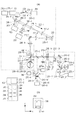
図2を用いて、ヘッド部102に内蔵される光学系について説明する。
<Configuration of optical system>
The optical system built in the
光源201−1から出射した光は、光カプラー231によって参照光205と測定光206−1とに分割される。測定光206−1は、シングルモードファイバー230−4、空間光変調器259、XYスキャナ219−1、ダイクロイックミラー270−1等を介して観察対象の被検査物である被検眼207を照射する。256は固視灯であり、固視灯256からの光束257は、観察対象の被検査物である被検眼207の固視あるいは回旋を促す役割を有する。
The light emitted from the light source 201-1 is split into the
測定光206−1は、被検眼207によって反射あるいは散乱された戻り光208となり、測定光路を逆行し、ビームスプリッタ258−3で反射されて、受光部700に入射される。受光部700を構成するディテクター704−1〜5(図8、図9参照)は、戻り光208の光強度を電圧信号に変換して出力し、その信号を用いて、被検眼207の眼底の平面画像が生成される。本実施形態では、光学系の全体を主にレンズを用いた屈折光学系を用いて構成しているが、レンズの代わりに球面ミラーを用いた反射光学系によっても構成しても良い。
The measurement light 206-1 becomes return light 208 reflected or scattered by the
また、収差補正デバイスとして反射型の空間光変調器を用いたが、透過型の空間光変調器や、可変形状ミラーを用いても構成しても良い。 Further, although a reflective spatial light modulator is used as an aberration correction device, a transmissive spatial light modulator or a deformable mirror may be used.
<AOSLO部の光源>
光源201−1の周辺について説明する。光源201−1は、代表的な低コヒーレント光源であるSLD(Super Luminescent Diode)光源である。波長は840nmバンド幅50nmである。スペックルノイズの少ない平面画像を取得するために低コヒーレント光源を選択している。また、光源の種類は、SLD光源を選択したが低コヒーレント光が出射できれば良くASE(Amplified Spontaneous Emission)光源等も用いることができる。
<Light source of AOSLO section>
The periphery of the light source 201-1 will be described. The light source 201-1 is an SLD (Super Luminescent Diode) light source that is a typical low-coherent light source. The wavelength is 840 nm and the bandwidth is 50 nm. A low coherent light source is selected to obtain a planar image with little speckle noise. As the type of light source, an SLD light source is selected, but it is sufficient if low coherent light can be emitted. An ASE (Amplified Spontaneous Emission) light source or the like can also be used.
また、波長は眼を測定することを考慮すると、近赤外光が適する。さらに、波長は得られる平面画像の横方向の分解能に影響するため、なるべく短波長であることが望ましく、ここでは840nmとする。観察対象の測定部位によっては他の波長を選んでも良い。 In consideration of measuring the eye, near infrared light is suitable for the wavelength. Furthermore, since the wavelength affects the resolution in the horizontal direction of the obtained planar image, it is desirable that the wavelength be as short as possible, here 840 nm. Other wavelengths may be selected depending on the measurement site to be observed.
光源201−1から出射された光は、シングルモードファイバー230−1と光カプラー231とを介して、参照光205と測定光206−1とに90:10の割合で分割される。253−2、253−4は偏光コントローラである。
The light emitted from the light source 201-1 is split into the
<AOSLO部の参照光路>
参照光205の参照光路について説明する。
<Reference optical path of AOSLO section>
The reference light path of the
光カプラー231によって分割された参照光205は、光ファイバー230−2を介して、光量測定装置264に入射される。光量測定装置264は参照光205の光量を測定することにより、測定光206−1の光量をモニターする用途に用いられる。
The
<AOSLO部の測定光路>
測定光206−1の測定光路について説明する。
<Measurement optical path of AOSLO section>
The measurement optical path of the measurement light 206-1 will be described.
光カプラー231によって分割された測定光206−1は、シングルモードファイバー230−4を介してレンズ235−1に導かれ、ビーム径4mmの平行光になるよう調整される。
The measurement light 206-1 split by the
測定光206−1は、ビームスプリッタ258−3、258−1を通過し、レンズ235−5〜6を通過し、空間光変調器259に照射される。
The measurement light 206-1 passes through the beam splitters 258-3 and 258-1, passes through the lenses 235-5 to -6, and is irradiated on the spatial
空間光変調器259は、ドライバ部281内の空間光変調器駆動ドライバ288を介して、制御PC106から制御される。
The spatial
測定光206−1は、空間光変調器259にて変調され、レンズ235−7〜8を通過し、XYスキャナ219−1のミラーに照射される。簡単のため、XYスキャナ219−1は一つのミラーとして図には記したが、実際にはXスキャナとYスキャナとの2枚のミラーが近接して配置され、網膜227上を光軸に垂直な方向に測定光206−1をラスタースキャンするものである。また、測定光206−1の中心がXYスキャナ219−1の各ミラーの回転中心と一致するように、XYスキャナ219−1の各ミラーは調整されている。
The measurement light 206-1 is modulated by the spatial
Xスキャナは測定光206−1を紙面に平行な方向に走査するスキャナであり、共振型スキャナを用いている。共振型スキャナの駆動周波数は約7.9kHzである。また、Yスキャナは、測定光206−1を紙面に垂直な方向に走査するスキャナであり、ガルバノスキャナを用いている。ガルバノスキャナの駆動波形はのこぎり波であり、周波数は32Hz、デューティ比は84%である。Yスキャナの駆動周波数は、AOSLO像の撮像のフレームレートを決定する重要なパラメータである。 The X scanner is a scanner that scans the measurement light 206-1 in a direction parallel to the paper surface, and uses a resonance scanner. The drive frequency of the resonant scanner is about 7.9 kHz. The Y scanner is a scanner that scans the measuring light 206-1 in a direction perpendicular to the paper surface, and uses a galvano scanner. The drive waveform of the galvano scanner is a sawtooth wave, the frequency is 32 Hz, and the duty ratio is 84%. The driving frequency of the Y scanner is an important parameter that determines the frame rate for capturing an AOSLO image.
XYスキャナ219−1は、ドライバ部281内の光スキャナ駆動ドライバ282を介して、制御PC106から制御される。
The XY scanner 219-1 is controlled by the
レンズ235−9〜10は、網膜227を測定光206−1で走査するための光学系であり、測定光206−1を被検眼207の瞳孔中心を支点として、網膜227をスキャンする役割がある。
The lenses 235-9 to 10 are optical systems for scanning the
測定光206−1のビーム径は4mmであるが、より高分解能な光画像を取得するためにビーム径はより大きくしても良い。 The beam diameter of the measurement light 206-1 is 4 mm, but the beam diameter may be larger in order to obtain a higher resolution optical image.
217−1は電動ステージであり、矢印で図示している方向に移動することができ、付随するレンズ235−10の位置を動かし、フォーカス位置を調整することができる。 217-1 is an electric stage, which can move in the direction shown by the arrow, and can adjust the focus position by moving the position of the associated lens 235-10.
電動ステージ217−1は、ドライバ部281内の電動ステージ駆動ドライバ283を介して、制御PC106から制御される。
The electric stage 217-1 is controlled from the
レンズ235−10の位置を調整することで、被検眼207の網膜227の所定の層に測定光206−1を合焦させ、網膜227を観察、撮像することが可能になる。また、被検眼207が屈折異常を有している場合にも対応できる。
By adjusting the position of the lens 235-10, the measurement light 206-1 is focused on a predetermined layer of the
測定光206−1が被検眼207に入射すると、網膜227からの反射や散乱により戻り光208となり、受光部700へ入射する。詳細については後述するが、入射した戻り光208は分岐部によって分岐されてディテクター704−1〜5にそれぞれ照射される。ディテクター704−1〜5は、例えば高速・高感度な光センサであるAPD(Avalanche Photo Diode)やPMT(Photomultiplier Tube)が用いられる。
When the measurement light 206-1 enters the
<受光部>
図7〜図9を用いて受光部700の構成について説明する。
<Light receiver>
The configuration of the
受光部700に入射した戻り光208は、レンズによる結像面に配置された分岐部711の中心部により、その一部の光は反射してディテクター704−1へ照射される。分岐部711により反射された一部の光を除く光の更に一部の光は、分岐部711を透過して、レンズによる結像面に配置された四角錐プリズム706によって4分割されて、ディテクター704−2、704−3、704−4、704−5へそれぞれ照射される(図9参照)。
A part of the
図7(a)に分岐部711を示す。図に示したように分岐部711は、中心部に反射領域714、反射領域714の外側の部分に透過領域712、遮光するための遮光領域713を形成したパターン715を1パターンとした複数のパターンを有している。そして、分岐部711を回転させることにより1つのパターンが選択され、選択されたパターンの中心部が戻り光208の光軸中心に位置するように配置される。
FIG. 7A shows a branching
分岐部711のパターン715の中心部の反射領域714で反射された光708は、ディテクター704−1に入射する。パターン715の透過領域712を通過した光709は、その結像面に配置された四角錐プリズム706によって4分割され、ディテクター704−2、704−3、704−4、704−5へそれぞれ入射する。ディテクター704−2、704−3はそれぞれXスキャナ219−2の走査方向と同軸上に配置され、ディテクター704−4、704−5はYスキャナ219−2の走査方向と同軸上に配置される。
The light 708 reflected by the
分岐部711は、分岐部711が戻り光208の光軸に対して斜めに配置されたときに、選択されたパターンの形状が光軸方向から見て円形になるような楕円形状のパターンを持っている。尚、簡単のため図においては各パターンを円形で示してある。また、分岐部711は、パターン選択制御部289を介して、制御PC106から1つのパターンが選択されるように制御される。
The branching
中心部の反射領域714の径が小さいパターンが選択されると、ディテクター704−1の出力に基づいて生成される共焦点画像(AOSLO像)は、光軸方向の分解能が上がるが焦点深度が狭まる。中心部の反射領域714の径を大きくすると光軸方向の分解能が下がり、焦点深度が広がる。また、ディテクター704−2〜5の各出力に基づいて生成される非共焦点画像は、反射領域714の径が小さく外側の透過領域712が大きいパターンが選択されると、各ディテクターが検出する信号強度が上がるため、生成する差分画像(非共焦点画像)の信号対雑音比(SN比)が大きくなる。中心部の反射領域714の径が大きく外側の透過領域712が小さいパターンが選択されると信号強度が下がるため信号対雑音比は小さくなる。
When a pattern with a small diameter of the
このため観察画像に応じて適切なパターンを選択することで、撮像する画像の分解能や信号対雑音比が良好になるように調整することができる。分岐部711は図7(a)に示すように円形に配置された複数のパターンを形成した板を機械的に回転させてパターンを選択できる構成である。あるいは、図7(b)のように1列に並んで配置された複数のパターンを機械的にスライドさせて選択できる構成でも良く、受光部700での戻り光を分割する構成はここに記載されている限りではない。
For this reason, by selecting an appropriate pattern according to the observed image, it is possible to adjust the resolution of the image to be captured and the signal-to-noise ratio. As shown in FIG. 7A, the
ディテクター704−1〜5で得られたそれぞれの電圧信号は、制御PC106内のADボード276−1にてデジタル値に変換され、制御PC106に入力される。
The respective voltage signals obtained by the detectors 704-1 to 704-5 are converted into digital values by the AD board 276-1 in the
ディテクター704−2、704−3、704−4、704−5に照射されたある時点の光から得た電圧信号のデジタル値をそれぞれIa、Ib、Ic、Idとする。(1)式および(2)式からX方向の信号成分およびY方向の信号成分である微分値Iabおよび微分値Icdを演算により取得する。
Iab=(Ia−Ib)/(Ia+Ib) ・・・(1)
Icd=(Ic−Id)/(Ic+Id) ・・・(2)
X方向およびY方向の信号成分である微分値IabおよびIcdによって生成した画像を用いて、輪郭強調した画像を取得することができる。
Digital values of voltage signals obtained from light at a certain point of time irradiated to the detectors 704-2, 704-3, 704-4, and 704-5 are denoted by Ia, Ib, Ic, and Id, respectively. The differential value Iab and the differential value Icd, which are the signal component in the X direction and the signal component in the Y direction, are obtained by calculation from the equations (1) and (2).
Iab = (Ia−Ib) / (Ia + Ib) (1)
Icd = (Ic−Id) / (Ic + Id) (2)
A contour-enhanced image can be acquired using images generated by the differential values Iab and Icd which are signal components in the X direction and the Y direction.
また、非共焦点画像を生成するための受光部の構成としてディテクターの数を4つとしてIa、Ib、Ic、Idを取得する構成を説明した。別な構成として、四角錐プリズムの分割点に対して線対称にディテクターを2つ配置し、四角錐プリズムとディテクターを光709の光軸に対して回転させる構成とすることで、Iabの値と回転角度θの情報を取得する構成としても良い。 In addition, the configuration in which Ia, Ib, Ic, and Id are acquired by using four detectors as the configuration of the light receiving unit for generating the non-confocal image has been described. As another configuration, two detectors are arranged symmetrically with respect to the dividing point of the quadrangular pyramid prism, and the quadrangular pyramid prism and the detector are rotated with respect to the optical axis of the light 709, so that the value of Iab is It is good also as a structure which acquires the information of rotation angle (theta).
<WFSLO部全体>
WFSLO部について図2を用いて説明する。WFSLO部は基本的にAOSLO部と同様の構成となっている。そのため重複する部分については説明を省略する。
<WFSLO section as a whole>
The WFSLO unit will be described with reference to FIG. The WFSLO section has basically the same configuration as the AOSLO section. Therefore, the description of the overlapping parts is omitted.
光源201−2から出射した光は、レンズ235−2、レンズ235−11〜14、XYスキャナ219−2、ダイクロイックミラー270−1〜3等を介して観察対象である被検眼207を照射する。光源201−2は、AOSLO部と同様にSLD光源である。波長は920nmバンド幅20nmである。
The light emitted from the light source 201-2 irradiates the
<WFSLO部の測定光路>
測定光206−2の測定光路について説明する。光源201−2から射出された測定光206−2は、レンズ235−2、レンズ235−11〜14、XYスキャナ219−2、ダイクロイックミラー270−1等を介して観察対象の被検査物である被検眼207に照射される。
<Measurement optical path of WFSLO section>
The measurement optical path of the measurement light 206-2 will be described. The measurement light 206-2 emitted from the light source 201-2 is an inspection object to be observed through the lens 235-2, lenses 235-11 to 14, the XY scanner 219-2, the dichroic mirror 270-1, and the like. The
XYスキャナ219−2の構成要素であるXスキャナは、測定光206−2を紙面に平行な方向に走査するスキャナであり、共振型スキャナを用いている。その駆動周波数は約3.9kHzである。また、Yスキャナは測定光206−2を紙面に垂直な方向に走査するスキャナであり、ガルバノスキャナを用いている。その駆動波形はのこぎり波であり、周波数は15Hz、デューティ比は84%である。Yスキャナの駆動周波数は、WFSLO像のフレームレートを決定する重要なパラメータである。 The X scanner, which is a component of the XY scanner 219-2, is a scanner that scans the measurement light 206-2 in a direction parallel to the paper surface, and uses a resonance scanner. The driving frequency is about 3.9 kHz. The Y scanner is a scanner that scans the measuring light 206-2 in a direction perpendicular to the paper surface, and uses a galvano scanner. The drive waveform is a sawtooth wave, the frequency is 15 Hz, and the duty ratio is 84%. The driving frequency of the Y scanner is an important parameter that determines the frame rate of the WFSLO image.
測定光206−2のビーム径は1mmであるが、より高分解能な光画像を取得するために、ビーム径をより大きくしても良い。 The beam diameter of the measurement light 206-2 is 1 mm, but the beam diameter may be increased in order to obtain a higher resolution optical image.
測定光206−2は、被検眼207に入射すると網膜227からの反射や散乱により戻り光208’となる。戻り光208’は、ダイクロイックミラー270−1〜3、レンズ235−13〜14、レンズ235−2〜4、XYスキャナ219−2、ビームスプリッタ258−2等を介してディテクター238−2に入射する。ディテクター238−2で検出された戻り光208’の電圧信号に基づき制御PC106がWFSLO像を生成する。
When the measurement light 206-2 is incident on the
<ビーコン部の説明>
次に、被検眼207にて発生する収差を測定するためのビーコン部について説明する。
<Description of the beacon part>
Next, a beacon unit for measuring aberration generated in the
光源201−3から射出された測定光206−3は、レンズ235−15〜16、ダイクロイックミラー270−4等を介して観察対象である被検眼207に照射される。
The measurement light 206-3 emitted from the light source 201-3 is irradiated to the
測定光206−3は、角膜226からの反射を避けるために、被検眼207の角膜中心から偏心して入射される。測定光201−3の戻り光208’’の一部は、ダイクロイックミラー258−1、ピンホール298を介して、波面センサ255に入射され、被検眼207で発生する戻り光208の収差が測定される。ピンホール298は、戻り光208’’以外の不要光を遮光する目的で設置されている。波面センサ255は、制御PC106に電気的に接続されている。波面センサ255は、シャックハルトマン方式の波面センサであり、測定レンジは−10D〜+5Dとなっている。波面センサ255で得られた収差情報は、制御PC106でツェルニケ多項式を用いて表現され、これは被検眼207による収差を示している。ツェルニケ多項式はチルト(傾き)の項、デフォーカスの項、アスティグマ(非点収差)の項、コマの項、トリフォイルの項等からなる。なお、光源201−3の中心波長は760nm、波長幅は20nmである。
In order to avoid reflection from the
角膜226とXYスキャナ219−1と波面センサ255と空間光変調器259とは、光学的に共役になるようレンズ235−5〜10等が配置されている。そのため、波面センサ255は、被検眼207による収差を測定することが可能になっている。また、空間光変調器259は被検眼207による収差を補正することが可能になっている。
The
<固視灯部>
固視灯256は、発光型のディスプレイモジュールからなり表示面(□27mm、128×128画素)をXY平面に有し、液晶、有機EL、LEDアレイ等を用いる。被検眼207が、固視灯256からの光束257を注視することで、被検眼207の固視あるいは回旋が促される。固視灯256の表示面には、例えば図2(b)に示すように、任意の点灯位置265に十字のパターンが点滅して表示される。
<Fixing light part>
The
固視灯256からの光束257は、レンズ235−17〜18、ダイクロイックミラー270−1〜3を介して網膜227に照射される。また、レンズ235−17、18は、固視灯256の表示面と網膜227とが光学的に共役になるよう配置される。また、固視灯256は、ドライバ部281内の固視灯駆動ドライバ284を介して、制御PC106から制御される。
A
<前眼部観察部>
前眼部観察部について説明する。
<Anterior segment observation unit>
The anterior ocular segment observation unit will be described.
前眼部照明光源201−4から出射された光は、被検眼207を照射し、その反射光がダイクロイックミラー207−1、2、4、レンズ235−19、20を介してCCDカメラ260に入射する。光源201−4は、中心波長740nmのLEDである。
The light emitted from the anterior illumination light source 201-4 irradiates the
<フォーカス、シャッター、乱視補正>
以上のように、ヘッド部102に内蔵される光学系は、AOSLO部、WFSLO部、ビーコン部、固視灯部、前眼部観察部からなる。この中でAOSLO部、WFSLO部、ビーコン部、固視灯部は、それぞれ個別に電動ステージ217−1〜4を持ち、4つの電動ステージを連動させて動かすことでフォーカス位置を調整している。ただし、個別にフォーカス位置を調整したい場合には、個別に電動ステージを動かすことで調整可能である。
<Focus, shutter, astigmatism correction>
As described above, the optical system built in the
また、AOSLO部、WFSLO部、ビーコン部はそれぞれシャッター(不図示)を備え、シャッターの開閉により個別に被検眼207に測定光を入射させるか否かを制御できる。ここではシャッターを用いたが、光源201−1〜3を直接ON/OFFすることにより、制御することもできる。同様に、前眼部観察部、固視灯部についても、光源201−4および固視灯256のON/OFFにより制御可能である。
Each of the AOSLO unit, the WFSLO unit, and the beacon unit includes a shutter (not shown), and can control whether measurement light is incident on the
また、レンズ235−10は交換可能になっており、被検眼207による収差(屈折異常)に合わせて球面レンズやシリンドリカルレンズを用いることができる。また1個のレンズに限らず、複数のレンズを組み合わせて設置することも可能である。
Further, the lens 235-10 can be exchanged, and a spherical lens or a cylindrical lens can be used in accordance with the aberration (refractive abnormality) caused by the
<波長>
AOSLO部、WFSLO部、ビーコン部、固視灯部、前眼部観察部に用いられている光源の波長分布を図3に示す。それぞれの光をダイクロイックミラー270−1〜4で分けるために、それぞれ異なる波長帯になるようにしている。なお、図3は各光源の波長の違いを示すものであり、その強度およびスペクトル形状を規定するものではない。
<Wavelength>
FIG. 3 shows the wavelength distribution of the light source used in the AOSLO unit, WFSLO unit, beacon unit, fixation lamp unit, and anterior segment observation unit. In order to divide each light by the dichroic mirrors 270-1 to 270-4, different wavelength bands are used. In addition, FIG. 3 shows the difference in wavelength of each light source, and does not define the intensity and spectrum shape.
<画像化>
撮像画像の生成について説明する。
<Imaging>
Generation of a captured image will be described.
ディテクター704−1〜5に照射された光は、それぞれ光の強度に応じた電圧信号に変換される。ディテクター704−1〜5で得られた電圧信号は、制御PC106内のADボード276−1でデジタル値に変換される。そして、制御PC106にて、XYスキャナ219−1の動作や駆動周波数と同期したデータ処理が行われ、AOSLO像(共焦点画像及び非共焦点画像)が生成される。ADボード276−1の取り込み速度は15MHzである。同様に、ディテクター238−2で得られた電圧信号は、制御PC106内のADボード276−2にてデジタル値に変換され、WFSLO像が生成される。
The light applied to the detectors 704-1 to 704-5 is converted into a voltage signal corresponding to the intensity of the light. The voltage signals obtained by the detectors 704-1 to 704-5 are converted into digital values by the AD board 276-1 in the
<制御ソフト画面>
図5を用いて、液晶モニター105に表示される制御ソフト画面について説明する。図5において、各符号はそれぞれ次のように対応する。
501は、撮像開始を指示するための実行ボタン
502は、処理終了を指示するためのSTOPボタン
503は、顎受け部の微調整を指示するための電動ステージボタン
504は、フォーカスを調整するためのフォーカス調整ボタン
505は、WFSLO像の撮像開始を指示するためのWFSLO撮像ボタン
506は、収差の測定開始を指示するための収差測定ボタン
507は、AOSLO像の撮像開始を指示するためのAOSLO撮像ボタン
511は、収差量の値が表示される収差補正表示部
512は、前眼部画像が表示される前眼部表示部
513は、固視灯256の点灯位置を指示するための固視灯位置表示部
514は、波面センサ255で検出されたハルトマン像が表示される波面センサ表示部
515は、WFSLO像が表示されるWFSLO表示部
516は、ディテクター238−2の出力信号の強度が表示されるWFSLO強度表示部
517は、WFSLO像の記録を指示するためのWFSLO記録ボタン
518は、AOSLO像が表示されるAOSLO表示部
519は、ディテクター704−1の出力信号の強度が表示されるAOSLO強度表示部
520は、AOSLO像の記録を指示するためのAOSLO記録ボタン
521は、自動フォーカスを指示するための自動フォーカスボタン
522は、収差補正の開始を指示するための収差補正ボタン
523は、設定されている撮像条件の変更を指示するための撮像条件設定ボタン
524は、撮像するAOSLO像の深さの調整を指示するための深さ調整ボタン
606は、非共焦点画像の輪郭強調モードを指示するための輪郭強調モードボタン
<画像閲覧ソフト画面>
図6を用いて、液晶モニター105に表示される画像閲覧ソフト画面について説明する。図6において、各符号はそれぞれ次のように対応する。
601は、共焦点画像が表示される共焦点画像表示部
602は、処理対象の画像を指定するための画像番号選択部
603は、表示された共焦点画像と非共焦点画像の画質を調整するための画質調整部
604は、輪郭を強調する角度を調整するための角度調整部605の調整範囲
605は、輪郭強調する角度を変化させるための角度調整部
606は、輪郭強調モードを指示するための輪郭強調モードボタン
611は、非共焦点画像が表示される非共焦点画像表示部
612は、分岐部711のパターンの変更を指示するための焦点深度調整部
<撮像手順>
本実施形態のAOSLO装置における撮像手順について図4〜5を用いて説明する。
<Control software screen>
The control software screen displayed on the liquid crystal monitor 105 will be described with reference to FIG. In FIG. 5, the respective symbols correspond as follows.
501 is an
The image browsing software screen displayed on the liquid crystal monitor 105 will be described with reference to FIG. In FIG. 6, each symbol corresponds as follows.
A confocal
An imaging procedure in the AOSLO apparatus of this embodiment will be described with reference to FIGS.
図4に撮像手順を示す。以下に、各工程について述べる。なお、特に明記が無い限り制御PC106から制御されているものである。
FIG. 4 shows the imaging procedure. Below, each process is described. Note that control is performed from the
(工程1)装置を立ち上げ各種確認を行う。 (Step 1) Start up the device and perform various checks.
操作者が制御PC106及びAOSLO装置の電源を入れると、装置内で測定用の制御ソフトが起動し、図5に示す制御ソフト画面を液晶モニター105に表示する。この状態で、被検者に顔を顔受け部104にセットしてもらう。
When the operator turns on the
(工程2)前眼部画像を取得する。 (Step 2) An anterior ocular segment image is acquired.
操作者により制御ソフト画面の実行ボタン501が押されると、前眼部表示部512に、CCDカメラ260で撮像される前眼部の画像を表示する。前眼部表示部512の中央に瞳孔の中心が略正しい状態で表示されていない場合は、操作者はジョイスティック107を用いてヘッド部102を略正しい位置に動かす。さらに調整が必要な場合は、操作者は制御画面上の電動ステージボタン503を押し、顎受け駆動部109を微動させる。
When the
(工程3)WFSLO像を取得する。 (Step 3) Acquire a WFSLO image.
略正しい状態で前眼部画像が表示された場合、ディテクター238−2で撮像されるWFSLO像を、WFSLO表示部515に表示する。固視灯位置表示部513で固視灯を中央位置に設定し、被検眼207の視線を中心に誘導する。
When the anterior segment image is displayed in a substantially correct state, the WFSLO image captured by the detector 238-2 is displayed on the
次に、操作者はWFSLO強度表示部516を見ながら、フォーカス調整ボタン504を用いて調整を指示する。操作者はWFSLO強度表示部516に表示される信号強度が大きくなるように調整を指示する。WFSLO強度表示部516には横軸時間、縦軸信号強度でWFSLO部のディテクター238−2で検出された信号強度を時系列に表示する。ここで、フォーカス調整ボタン50の調整が指示されることで、レンズ235−10、14、16、18の位置を同時に移動させ、フォーカス位置を調整する。
Next, the operator instructs adjustment using the
WFSLO表示部515にWFSLO像が鮮明に表示されたことを確認した操作者がWFSLO記録ボタン517を押すことに応じて、WFSLOデータを保存部(不図示)に保存する。
When the operator who has confirmed that the WFSLO image is clearly displayed on the
(工程4)AOSLO像の取得位置を決定する。 (Step 4) The acquisition position of the AOSLO image is determined.
操作者はWFSLO表示部515に表示されたWFSLO像を確認し、AOSLO像を取得したい位置を後述の手段を用いて決める。その位置がWFSLO表示部515の中央にくるように被検眼207の視線を固視灯256を用いて誘導する。
The operator confirms the WFSLO image displayed on the
AOSLO像を取得する位置を決める手段は2通りある。一つは固視灯位置表示部513において固視灯の位置を操作者が指示する方法であり、指示された位置の固視灯を点灯する。もう一つはWFSLO表示部515において操作者が所望の位置を指示する方法である。WFSLO表示部515上の画素と固視灯の位置を関連付けて記憶しており、指示に応じて固視灯の位置を自動的に移動し、視線を所望の位置に誘導する。
There are two means for determining the position for acquiring the AOSLO image. One is a method in which the operator designates the position of the fixation lamp in the fixation lamp
AOSLO像を取得したい位置がWFSLO表示部515上中央に移動したのを確認した操作者からの指示に応じて、次の工程に移る。
In response to an instruction from the operator who has confirmed that the position where the AOSLO image is to be acquired has moved to the center on the
(工程5)収差補正を行う。 (Step 5) Aberration correction is performed.
操作者が収差測定ボタン506を押すと、WFSLO測定光である測定光206−2を遮断し、光源201−3から射出されるビーコン光のシャッターを開いてビーコン光である測定光206−3を被検眼207に照射する。波面センサ表示部514に、波面センサ255で検出されたハルトマン像を表示する。このハルトマン像から演算された収差を、収差補正表示部511に表示する。収差はデフォーカス(defocus)成分(μm単位)と、全ての収差量(μmRMS単位)に分けて表示される。ここで、工程3において、AOSLO測定光とビーコン光のフォーカスレンズであるレンズ235−10、16の位置が調整されているため、この工程で収差測定の準備ができている。具体的には、測定光206−3に対する戻り光208’’が、ピンホール298をけられることなく通過し、波面センサ255に到達する状態になっている。
When the operator presses the
ここで自動フォーカスボタン521が押されると、デフォーカスの値が小さくなるようにレンズ235−10、14、16、18の位置を調整する。
Here, when the
操作者が収差補正ボタン522を押すと、収差量が小さくなる方向に空間光変調器259を調整し、リアルタイムに収差量の値を表示する。収差量の値が事前に設定された閾値(0.03μmRMS)以下になると自動的にAOSLO撮像ボタン507が押された状態となり、次の工程に移動する。収差量の閾値は任意に設定できる。また、閾値以下にならない場合には、操作者が収差補正一時停止ボタン508を押し、収差補正を停止させたのち、AOSLO測定ボタン507を押すことにより次の工程に移動させることもできる。
When the operator presses the
(工程6)AOSLO像を取得する。 (Step 6) An AOSLO image is acquired.
操作者がAOSLO撮像ボタン507を押すと、ビーコン光である測定光206−3を遮断し、AOSLO測定光206−1のシャッターを開いて測定光206−1を被検眼207に照射する。AOSLO表示部518に収差補正済みのAOSLO像を表示する。また、AOSLO強度表示部519に、WFSLO強度表示部516と同様に、AOSLO部のディテクター704−1で検出された信号強度を時系列に表示する。
When the operator presses the
操作者は、信号強度が不十分な場合には、AOSLO強度表示部519を見ながらフォーカス位置、顎受け位置を調整し、信号強度が大きくなるように調整を指示する。
When the signal strength is insufficient, the operator adjusts the focus position and the chin rest position while looking at the AOSLO
また、操作者は、撮像条件設定ボタン523を使用することによって、撮像画角、フレームレート、撮像時間を指示することができる。
Further, the operator can instruct the imaging angle of view, the frame rate, and the imaging time by using the imaging
また、操作者は、深さ調整ボタン524を調整して、レンズ235−10を移動させ、被検眼207の深さ方向の撮像範囲を調整することができる。具体的には、視細胞層や神経線維層や色素上皮層等の所望の層の像を取得させることができる。
Further, the operator can adjust the imaging range in the depth direction of the
AOSLO表示部518にAOSLO像が鮮明に表示されたことを確認した操作者が、AOSLO記録ボタン520を押したことに応じて、AOSLOデータを保存部へ保存する。その後、測定光206−1を遮断する。なお、操作者がAOSLO像の焦点深度を変えたい場合は、分岐部711のパターンの反射領域の大きさの変更するために焦点深度調整部612を切り替えることに応じて、分岐部711のパターンを変更し、再度AOSLO像を撮像すれば良い。
When the operator who has confirmed that the AOSLO image is clearly displayed on the
(工程7)AOSLO像の輪郭強調像を表示する。 (Step 7) A contour-enhanced image of the AOSLO image is displayed.
輪郭強調モードボタン606(図5参照)が押されると、AOSLO像を輪郭強調した画像の表示に切り替える。即ち、図5に示す表示から、図6に示す表示に切り替える。 When the contour emphasis mode button 606 (see FIG. 5) is pressed, the AOSLO image is switched to display an image with contour emphasis. That is, the display shown in FIG. 5 is switched to the display shown in FIG.
操作者が図6における角度調整部605を回転させると、回転角度に応じてAOSLO像を輪郭強調する角度が変化する。
再度輪郭強調モードボタン606(図6参照)を押されると、通常のAOSLO像の表示に切り替える(図6から図5へ切り替える)。なお、操作者が輪郭強調した画像の焦点深度を変えたい場合は、分岐部711のパターンの透過領域の大きさが変わるようにパターンの変更を指示し、再度AOSLO像を撮像すれば良い。
When the operator rotates the
When the contour emphasis mode button 606 (see FIG. 6) is pressed again, the display is switched to normal AOSLO image display (switch from FIG. 6 to FIG. 5). Note that when the operator wants to change the depth of focus of the image whose contour is emphasized, it is sufficient to instruct the change of the pattern so that the size of the transmission region of the pattern of the branching
(工程8)次の動作を選択する。 (Step 8) The next operation is selected.
撮像位置の変更を行う場合には工程4に、左右眼の切り替えを行う場合には工程2に戻る。撮像を終了する場合には、工程9に移動する。 If the imaging position is changed, the process returns to step 4; When the imaging is finished, the process moves to step 9.
(工程9)終了する。 (Step 9) The process ends.
STOPボタン502が押されると、処理を終了する。
When the
<画像の確認>
次に、本実施形態のAOSLO装置において撮像したデータを画像化して確認する方法について図6を用いて説明する。
<Confirmation of image>
Next, a method for converting the imaged data in the AOSLO apparatus of this embodiment into an image and confirming it will be described with reference to FIG.
操作者からの指示に基づき、撮像した画像データを可視化する画像閲覧ソフトを起動し、図6に示す画像閲覧ソフト画面を液晶モニター105に表示する。
Based on an instruction from the operator, image browsing software for visualizing the captured image data is activated, and the image browsing software screen shown in FIG. 6 is displayed on the
保存されたWFSLOデータ、もしくはAOSLOデータを読み込んで画像化することができる。 The stored WFSLO data or AOSLO data can be read and imaged.
操作者は、画像番号選択部602への画像番号の入力等よって表示する画像を指定する。撮像時間順に画像番号が付けられて保存されている画像データから、指定された画像番号の画像データを保存部から読み出し、それぞれ共焦点画像表示部601と非共焦点画像表示部611に同時に表示する。
The operator designates an image to be displayed by inputting an image number to the image
画質調整部603には、画像の明るさ、コントラスト、ガンマの調整を行うためのつまみがあり、左右にスライドさせることで共焦点画像表示部601と非共焦点画像表示部611に表示された画像の画質の調整を指示することができる。
The image
非共焦点画像表示部611にはディテクター704−2〜5によって生成した眼底の輪郭強調画像を表示する。また、共焦点画像表示部601および非共焦点画像表示部611の表示は、輪郭強調モードボタン606によって、非共焦点画像と共焦点画像の表示を切り替える構成としても良い。
The non-confocal
操作者は、非共焦点画像表示部611に表示された非共焦点画像の輪郭を強調する角度を調整するための角度調整部605は調整範囲604の円周上を360°回転する。(3)式より回転角度θに応じた値(x,y)を求め、X方向およびY方向の信号成分である微分値IabおよびIcdに掛け合わせることで各々の信号の割合を変更する。そして変更して得た値Iadを画像化して表示することで角度調整部605の角度に応じた陰影の画像を表示する。Iadは(4)式を用いた演算によって得られる。
x=1cosθ
y=lsinθ ・・・(3)
Iad=xIab+yIcd ・・・(4)
上記Iadによって取得した視細胞画像610が角度調整部605の回転角度に応じて演算されて眼底画像を表示することにより、図10のように例えば眼底の視細胞画像の陰影の向きを調整することができる。
An operator adjusts the angle for emphasizing the outline of the non-confocal image displayed on the non-confocal
x = 1 cos θ
y = lsin θ (3)
Iad = xIab + yIcd (4)
The
ここで、角度調整部605に代わる角度調整用のインターフェースは機械的なボリュームの角度θを調整する方法でも良い。または、表示画像の中心から画像上を選択した点を結ぶ線と、画像の水平線とのなす角度をθとして角度を決定する方法でも良く、その調整手段はこの限りではない。
Here, an interface for angle adjustment instead of the
以上のように、ディテクター704−2〜5による4つの信号を用いる事で、任意の角度による陰影を持った画像表示を行うことができ、より自由度の高い詳細な観察画像を得る事が可能となる。 As described above, by using the four signals from the detectors 704-2 to -5, it is possible to display an image with a shadow at an arbitrary angle, and to obtain a detailed observation image with a higher degree of freedom. It becomes.
[実施形態2]
実施形態1において、4つのディテクターによる輪郭強調(陰影調整)について説明した。本実施形態2においては、2つのディテクターによる輪郭強調(陰影調整)について説明する。
[Embodiment 2]
In the first embodiment, the edge enhancement (shadow adjustment) using the four detectors has been described. In the second embodiment, contour enhancement (shadow adjustment) using two detectors will be described.
図9に示した受光部700の構成が、図11に示すように三角柱の形状をしたナイフエッジプリズム720で2分割して受光ディテクター704−6と704−7で受光する構成とする。また、図12に示すようにミラー721のエッジで2分割して受光ディテクター704−6と704−7で受光する構成としても良い。
The configuration of the
これらの構成の場合、図7の分岐部711の構成は、図13のような構成として受光ディテクター704−6と704−7に入射するように透過領域712を2分岐させる構成とする。
In the case of these configurations, the configuration of the branching
さらにこの場合、信号成分の強度を求める(1)式は前述の通りであり、(2)式が、Icd=0となる。 Further, in this case, the expression (1) for obtaining the intensity of the signal component is as described above, and the expression (2) is Icd = 0.
また、この場合のモニター105には調整範囲604の代わりにスライダー調整範囲607で、下記の演算式のxを調整指示が可能とする調整部608を設ける。
Icd=xIad(−1≦x≦+1、x≠0)
この調整部608によって係数xの調整を指示することで、図14のようにx方向の陰影の割合を調整する構成としても良い。
In addition, the
Icd = xIad (−1 ≦ x ≦ + 1, x ≠ 0)
By instructing the adjustment of the coefficient x by the adjusting
以上のように、2つのディテクターによる構成とすることで、前述した4つのディテクターによる構成よりも簡易的な構成で、従来の輪郭強調の調整機構がない構成よりも自由度が高く詳細な観察画像の特徴を得る事が可能となる。 As described above, the configuration with two detectors is a simpler configuration than the configuration with the four detectors described above, and has a higher degree of freedom and a detailed observation image than the configuration without the conventional contour enhancement adjustment mechanism. It is possible to obtain the characteristics of
(その他の実施形態)
本発明の目的は、前述した実施形態の機能を実現するソフトウェアのプログラムコードを記憶した記憶媒体を、システムあるいは装置に供給する。そして、そのシステムあるいは装置のコンピュータ(またはCPUやMPU)が記憶媒体に格納されたプログラムコードを読出し実行することによっても、達成されることは言うまでもない。
(Other embodiments)
An object of the present invention is to supply a storage medium storing software program codes for realizing the functions of the above-described embodiments to a system or apparatus. Needless to say, this can also be achieved by the computer (or CPU or MPU) of the system or apparatus reading and executing the program code stored in the storage medium.
Claims (11)
前記複数の光の強度をそれぞれ測定する受光手段と、
前記光の強度に基づいて生成する画像の信号成分の割合を変更する変更手段と、
前記変更された信号成分を用いた演算により画像を生成する生成手段と、
を有することを特徴とする光画像撮像装置。 Branching means for branching the return light obtained by irradiating the inspection object with the measurement light from the light source through the measurement optical path, into a plurality of lights;
A light receiving means for measuring the intensity of each of the plurality of lights;
Changing means for changing a ratio of signal components of an image to be generated based on the intensity of the light;
Generating means for generating an image by calculation using the changed signal component;
An optical image pickup device comprising:
前記変更手段は、前記指定された角度に基づいて前記信号成分の割合を変更することを特徴とする請求項1に記載の光画像撮像装置。 A designating unit for designating an angle;
The optical image capturing apparatus according to claim 1, wherein the changing unit changes a ratio of the signal component based on the designated angle.
前記変更手段は、指定された大きさに応じて前記信号成分の
割合を変更することを特徴とする請求項1に記載の光画像撮像装置。 Further comprising designation means for designating the magnitudes of the plurality of light beams to be branched;
The optical image capturing apparatus according to claim 1, wherein the changing unit changes a ratio of the signal component according to a designated size.
前記第一の分岐部は、前記複数の光の強度を変更できることを特徴とする請求項1に記載の光画像撮像装置。 The branching unit is composed of a first branching part that branches the central part of the return light, and a second branching part that branches a part outside the central part into a plurality of parts,
The optical image capturing apparatus according to claim 1, wherein the first branching unit can change the intensity of the plurality of lights.
前記指定された角度に基づいて、前記2分割した光の強度から生成する信号成分の割合を変更することを特徴とする請求項5に記載の光画像撮像装置。 A designating unit for designating an angle;
6. The optical image capturing apparatus according to claim 5, wherein a ratio of a signal component generated from the intensity of the light divided into two is changed based on the designated angle.
前記指定された角度に基づいて、前記4分割した光の強度から生成する信号成分の割合を変更することを特徴とする請求項6に記載の光画像撮像装置。 A designating unit for designating an angle;
The optical image capturing apparatus according to claim 6, wherein a ratio of a signal component generated from the intensity of the light divided into four is changed based on the specified angle.
前記表示手段は、前記角度を指定するための画像を前記生成された画像と共に表示することを特徴とする請求項2に記載の光画像撮像装置。 It further has display means for displaying an image generated by the generation means,
The optical image capturing apparatus according to claim 2, wherein the display unit displays an image for designating the angle together with the generated image.
前記複数の光の強度をそれぞれ測定する受光工程と、
前記光の強度に基づいて生成する画像の信号成分の割合を変更する変更工程と、
前記変更された信号成分を用いた演算により画像を生成する生成工程と、
を有することを特徴とする光画像撮像装置の制御方法。 A branching step of branching the return light obtained by irradiating the inspection object with the measurement light from the light source through the measurement optical path into a plurality of lights;
A light receiving step for measuring the intensity of each of the plurality of lights;
A changing step of changing a ratio of signal components of an image to be generated based on the light intensity;
A generating step of generating an image by calculation using the changed signal component;
A method for controlling an optical image pickup apparatus, comprising:
Priority Applications (3)
| Application Number | Priority Date | Filing Date | Title |
|---|---|---|---|
| JP2015080445A JP6494385B2 (en) | 2014-07-16 | 2015-04-09 | Optical image pickup apparatus and control method thereof |
| US15/326,436 US10485419B2 (en) | 2014-07-16 | 2015-06-30 | Optical imaging apparatus and method for controlling the same |
| PCT/JP2015/003297 WO2016009603A1 (en) | 2014-07-16 | 2015-06-30 | Optical imaging apparatus and method for controlling the same |
Applications Claiming Priority (3)
| Application Number | Priority Date | Filing Date | Title |
|---|---|---|---|
| JP2014145915 | 2014-07-16 | ||
| JP2014145915 | 2014-07-16 | ||
| JP2015080445A JP6494385B2 (en) | 2014-07-16 | 2015-04-09 | Optical image pickup apparatus and control method thereof |
Publications (2)
| Publication Number | Publication Date |
|---|---|
| JP2016028674A JP2016028674A (en) | 2016-03-03 |
| JP6494385B2 true JP6494385B2 (en) | 2019-04-03 |
Family
ID=53762257
Family Applications (1)
| Application Number | Title | Priority Date | Filing Date |
|---|---|---|---|
| JP2015080445A Active JP6494385B2 (en) | 2014-07-16 | 2015-04-09 | Optical image pickup apparatus and control method thereof |
Country Status (3)
| Country | Link |
|---|---|
| US (1) | US10485419B2 (en) |
| JP (1) | JP6494385B2 (en) |
| WO (1) | WO2016009603A1 (en) |
Families Citing this family (5)
| Publication number | Priority date | Publication date | Assignee | Title |
|---|---|---|---|---|
| JP2016150090A (en) * | 2015-02-17 | 2016-08-22 | キヤノン株式会社 | Imaging apparatus and control method of the same |
| JP2016168257A (en) | 2015-03-13 | 2016-09-23 | キヤノン株式会社 | Ophthalmologic apparatus, control method thereof, and program |
| JP6882032B2 (en) * | 2017-03-27 | 2021-06-02 | キヤノン株式会社 | Ophthalmic imaging device and its control method |
| FR3065365B1 (en) * | 2017-04-25 | 2022-01-28 | Imagine Eyes | MULTI-SCALE RETINAL IMAGING SYSTEM AND METHOD |
| CN111289924A (en) * | 2018-12-10 | 2020-06-16 | 中科知影(北京)科技有限公司 | Multi-channel atomic magnetic detector |
Family Cites Families (10)
| Publication number | Priority date | Publication date | Assignee | Title |
|---|---|---|---|---|
| TW200419279A (en) * | 2003-03-28 | 2004-10-01 | Adv Lcd Tech Dev Ct Co Ltd | Method and apparatus for forming crystalline portions of semiconductor film |
| JP5269396B2 (en) | 2007-09-29 | 2013-08-21 | 株式会社ニデック | Fundus photographing device |
| JP5455001B2 (en) | 2008-12-26 | 2014-03-26 | キヤノン株式会社 | Optical tomographic imaging apparatus and control method for optical tomographic imaging apparatus |
| JP5590831B2 (en) * | 2009-07-13 | 2014-09-17 | キヤノン株式会社 | Image processing apparatus and image processing method |
| JP2011200367A (en) * | 2010-03-25 | 2011-10-13 | Fujifilm Corp | Image pickup method and device |
| JP6039908B2 (en) * | 2012-02-21 | 2016-12-07 | キヤノン株式会社 | IMAGING DEVICE AND IMAGING DEVICE CONTROL METHOD |
| JP6061498B2 (en) * | 2012-06-01 | 2017-01-18 | キヤノン株式会社 | Ophthalmic equipment |
| JP6041540B2 (en) * | 2012-06-01 | 2016-12-07 | キヤノン株式会社 | Ophthalmic equipment |
| JP2013248254A (en) * | 2012-06-01 | 2013-12-12 | Canon Inc | Ophthalmic device |
| JP6041538B2 (en) * | 2012-06-01 | 2016-12-07 | キヤノン株式会社 | Ophthalmic equipment |
-
2015
- 2015-04-09 JP JP2015080445A patent/JP6494385B2/en active Active
- 2015-06-30 WO PCT/JP2015/003297 patent/WO2016009603A1/en active Application Filing
- 2015-06-30 US US15/326,436 patent/US10485419B2/en not_active Expired - Fee Related
Also Published As
| Publication number | Publication date |
|---|---|
| WO2016009603A1 (en) | 2016-01-21 |
| JP2016028674A (en) | 2016-03-03 |
| US10485419B2 (en) | 2019-11-26 |
| US20170196450A1 (en) | 2017-07-13 |
Similar Documents
| Publication | Publication Date | Title |
|---|---|---|
| US8851673B2 (en) | Imaging apparatus | |
| JP6041538B2 (en) | Ophthalmic equipment | |
| JP6494385B2 (en) | Optical image pickup apparatus and control method thereof | |
| JP2013248260A (en) | Imaging apparatus, control method, and program | |
| US9339185B2 (en) | Imaging apparatus that acquires a first image and, via an aberration correction unit, a second image of an area corresponding to a part of the first image | |
| JP6882032B2 (en) | Ophthalmic imaging device and its control method | |
| JP2013248254A (en) | Ophthalmic device | |
| US10433721B2 (en) | Ophthalmic apparatus and control method for the same | |
| JP6041539B2 (en) | Ophthalmic equipment | |
| JP6061498B2 (en) | Ophthalmic equipment | |
| US10271726B2 (en) | Imaging apparatus and control method for the same | |
| JP6045200B2 (en) | Optical imaging device | |
| JP2020151094A (en) | Ophthalmologic apparatus | |
| JP2019213752A (en) | Ophthalmologic apparatus and control method of ophthalmologic apparatus | |
| JP2016168192A (en) | Image capturing apparatus and control method therefor | |
| JP7030577B2 (en) | Ophthalmic equipment | |
| JP2017144058A (en) | Ophthalmic apparatus and control method therefor, and program | |
| JP2020078649A (en) | Ophthalmologic apparatus, control method thereof, and program | |
| JP6633939B2 (en) | Inspection device | |
| JP2023126596A (en) | Ophthalmologic apparatus and control method thereof | |
| JP2016002177A (en) | Ophthalmologic apparatus | |
| JP2019213751A (en) | Ophthalmologic apparatus and control method thereof | |
| JP2020006105A (en) | Ophthalmologic device and control method thereof | |
| JP2020151096A (en) | Ophthalmologic apparatus | |
| JP2019130046A (en) | Ophthalmologic apparatus |
Legal Events
| Date | Code | Title | Description |
|---|---|---|---|
| A621 | Written request for application examination |
Free format text: JAPANESE INTERMEDIATE CODE: A621 Effective date: 20180329 |
|
| TRDD | Decision of grant or rejection written | ||
| A01 | Written decision to grant a patent or to grant a registration (utility model) |
Free format text: JAPANESE INTERMEDIATE CODE: A01 Effective date: 20190205 |
|
| A61 | First payment of annual fees (during grant procedure) |
Free format text: JAPANESE INTERMEDIATE CODE: A61 Effective date: 20190305 |
|
| R151 | Written notification of patent or utility model registration |
Ref document number: 6494385 Country of ref document: JP Free format text: JAPANESE INTERMEDIATE CODE: R151 |