JP4363719B2 - Ultrasound-guided puncture system device - Google Patents
Ultrasound-guided puncture system device Download PDFInfo
- Publication number
- JP4363719B2 JP4363719B2 JP28863399A JP28863399A JP4363719B2 JP 4363719 B2 JP4363719 B2 JP 4363719B2 JP 28863399 A JP28863399 A JP 28863399A JP 28863399 A JP28863399 A JP 28863399A JP 4363719 B2 JP4363719 B2 JP 4363719B2
- Authority
- JP
- Japan
- Prior art keywords
- puncture
- guide tube
- lumen
- ultrasonic
- distal end
- Prior art date
- Legal status (The legal status is an assumption and is not a legal conclusion. Google has not performed a legal analysis and makes no representation as to the accuracy of the status listed.)
- Expired - Fee Related
Links
Images


Description
【0001】
【発明の属する技術分野】
本発明は、末梢気管支、膵管・胆管など深部管腔臓器において超音波像下に穿刺針をガイドし穿刺を行う超音波ガイド下穿刺システム装置に関する。
【0002】
【従来の技術】
近年、腫瘍の良性悪性の判断など確定診断を得るための超音波ガイド下による穿刺術が注目を浴びている。特に最近は内視鏡の先端に前方もしくは側方を走査可能な超音波探触子を設け、内視鏡の鉗子チャンネルから突出させた穿刺針を超音波画像上に描出することが可能な穿刺用超音波内視鏡が提案され、体腔内からの超音波ガイド下穿刺も可能となった。
【0003】
このような超音波下穿刺可能な超音波内視鏡としては、例えば特開平6−105847号公報によって提案されている超音波内視鏡がある。この提案による超音波内視鏡では、超音波送受信手段と、この超音波受信手段による検査方向に穿刺針を穿刺自在に導出する導出口と、この導出口から導出された穿刺針を観察する観察光学窓と、を生体挿入部の先端構成部に備えた内視鏡において、前記超音波送受信手段、導出口、及び観察光学窓は、生体挿入部の長手方向の同一線上に配置されことを特徴としている。
【0004】
このような構成によれば、超音波送受信手段、導出口、及び観察光学窓を生体挿入部の長手方向の同一線上に配置しているので、観察光学窓から観察される像中心に、超音波断層像の中心と穿刺針の導出方向とが一致することになり、よって、穿刺針を正面から目視観察できるため、穿刺針による処置が正確に行い易くなる。
【0005】
【発明が解決しようとする課題】
しかしながら、上述した特開平6−105847号公報に提案されている従来の超音波内視鏡では、該穿刺用超音波内視鏡の挿入部が、直径φ10mm以上で構成されているため、未梢気管支や膵管・胆管などの細い管腔や、高度や狭窄部位には挿入不可能である。また、内視鏡の鉗子チャンネルを通して体腔内超音波検査を行うための細径超音波プローブであればこれらの部位への挿入は可能であるが、穿刺のガイドを行うのは非常に困難であるという問題点もあった。
【0006】
そこで、本発明は上記問題点に鑑みてなされたもので、印加気管支、膵管・胆管などの深部部位においても、超音波ガイド下穿刺処置を安全且つ確実に行うことができる超音波ガイド下穿刺システム装置、及びこの装置用ガイドチューブを提供することを目的とする。
【0007】
本発明の超音波ガイド下穿刺システム装置は、細長い挿入部の先端側に超音波振動子を有する超音波プローブと、穿刺針と、前記超音波プローブ及び前記穿刺針が挿通可能な少なくとも2つの第1及び第2のルーメンを有するガイドチューブとを含んで構成される超音波ガイド下穿刺システム装置において、
前記穿刺針は、その先端部近傍が略一定の曲率の曲がり癖を有して構成され、前記ガイドチューブの前記穿刺針が挿通される第2のルーメンの先端側開口部付近は、該ルーメンの中心軸が弧となるような略一定の曲率を有して構成されていると共に、前記ガイドチューブ先端の前記第1のルーメンと第2のルーメンとの開口部の間に凸状の穿刺位置指標を設けている。
また、本発明の超音波ガイド下穿刺システム装置用ガイドチューブは、細長い挿入部の先端側に超音波振動子を有する超音波プローブを挿通する第1のルーメンと、穿刺針を挿通する第2のルーメンとを有して体腔内に挿入可能に細長に形成され、前記穿刺針を挿通する第2のルーメンの先端付近を先端に向かうにしたがって前記第1のルーメンから徐々に離れていくように弧状に形成すると共に、先端の前記第1のルーメンと第2のルーメンとの開口部の間に凸状の穿刺位置指標を設けている。
【0008】
本発明によれば、穿刺針が、その先端部近傍が略一定の曲率の曲り癖を有して構成されるとともに、前記ガイドチューブの前記穿刺針が挿通される第1のルーメンの先端側開口部付近が、該ルーメンの中心軸が弧となるような略一定の曲率を有して構成されることにより、穿刺針は確実にガイドチューブの側方に向かって突出させることが可能となる。よって、末梢気管支、膵管・胆管等においても体腔内からのリアルタイムな超音波ガイド下穿刺処置を行うことが可能となる。
【0009】
【発明の実施の形態】
以下、図面を参照しながら本発明の実施の形態について説明する。
【0010】
第1の実施の形態:
図1乃至図12は本発明に係る超音波ガイド下穿刺システム装置の第1の実施の形態を示し、図1は該超音波ガイド下穿刺システム装置の全体構成を示す構成図、図2は該装置の先端部の構成を示す断面図、図3は穿刺針の構成を示す構成図、図4はガイドチューブ先端部の構成を示す断面図、図5は超音波プロープの構成を示す構成図、図6は手元操作部の構成を示す構成図、図7はガイドチューブコネクタの構成を示す断面図、図8は穿刺用ハンドルの構成を示す断面図、図9は穿刺針挿入用スタイレットの構成を示す構成図、図10は穿刺針挿入用ガードの構成を示す構成図、図11は該装置の主要動作を説明するための説明図、図12は穿刺用ハンドル動作を説明するための説明図である。
【0011】
(構成)
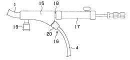
図1に示すように、本実施の形態の超音波ガイド下穿刺システム装置において、内視鏡の鉗子チャンネル等を通して体腔内へ挿入するガイドチューブ1には超音波プローブ4及び穿刺針5(図示せず)が挿通されており、その手元側にはガイドチューブコネクタ15が設けられている。
【0012】
ガイドチューブコネクタ15には、穿刺針5の操作を行う穿刺用ハンドル17が着脱自在に取付けられており、超音波プローブ4は、ガイドチューブコネクタ15からさらに手元側に延在し、接続部14を介して図示しない駆動装置に接続されるようになっている。
【0013】
前記超音波ガイド下穿刺システム装置の先端部の構成を説明すると、図2に示すような構成となっている。つまり、図2に示すように、ガイドチューブ1は、2つのルーメン2,3を内装している。一方のルーメン2には、超音波プローブ4が挿通されており、他方のルーメン3には、穿刺針5が挿通されている。
【0014】
本発明の超音波ガイド下穿刺システム装置では、前記穿刺針5及びこれが内装されるガイドチューブ先端部の構成に改良を施したことが特徴である。
【0015】
前記穿刺針5は、図3(a)に示すようにステンレス等金属製の中空パイプで構成されており、先端部にはほぼ一定の曲率で曲り癖6を形成している。また、図示はしないが穿刺針5先端部付近には、凹凸加工(例えばディンプル加工)が施されている。穿刺針5の手元側端部には、穿刺針ルア口金27及びルア口金用蓋30が取付られるようになっている。
【0016】
なお、穿刺針5の材質は、ステンレス等の金属に限らず、必要な弾性と強度及び生体適合性を有する材質であれば何でもよい。また、図3(b)に示すように、ルア口金用蓋30にスタイレット55を固定しておき、穿刺針5内にスタイレット55を挿通した構成としても良い。
【0017】
また、ガイドチューブ先端部は、図4及び図13に示すように構成されている。図4に示すようにガイドチューブ1には、超音波プローブ挿通用のルーメン2と穿刺針5挿通用のルーメン3とが設けられている。前記穿刺針5を挿通するルーメン3の先端付近は、該ルーメンの軸が弧となるように曲率7を設けて形成されている。この曲率7は、ルーメン3の軸が先端部において先端に向かうにしたがって前記超音波プローブ挿通用のルーメン2から徐々に離れていくように形成されている。前記ルーメン2及び3は、それぞれ挿通される超音波プローブ4、穿刺針5と適度な隙間(例えば0.1〜0.5mm)があくような内径を有している。また、ガイドチューブ1の素材は、ポリテトラフルオロエチレン、ポリエチレン、ポリウレタン、ポリエーテルブロックアミド、ナイロンなど適度な柔軟性を持つ樹脂で構成されている。なお、本実施例では、ガイドチューブ1の外径は、内視鏡の鉗子チャンネルに挿通可能な4mm以下で構成されることが望ましい。
前記ガイドチューブ1の先端部は、具体的には図13に示すように構成されている。すなわち、本実施の形態のガイドチューブ1は、穿刺指標付きガイドチューブ36となっている。この穿刺指標付きガイドチューブ36は、先端のルーメン2の開口部とルーメン3の開口部との間に、凸状の穿刺位置指標35を少なくとも1つ設けている。この穿刺位置指標35の材質は、超音波を反射する材質であれば何でも良い。
この穿刺指標付きガイドチューブ36の作用は、穿刺位置指標35を超音波画像上で捉えることにより、穿刺針5の突出方向を容易且つ確実に確認することができる。これにより、穿刺針5の突出方向と病変部方向とを合わせる作業を容易に且つ確実に行うことが可能となる。
したがって、この穿刺指標付きガイドチューブ36によれば、超音波ガイド下穿刺処置の作業性を向上させることができる。
【0018】
一方、ガイドチューブ1の先端部に配置された超音波プローブ4は、図5に示すように、挿入部13と接続部14とで構成されている。挿入部13は、図5中上段の拡大図に示すように、超音波振動子8を保持したハウジング9をフレキシブルシャフト10の先端に接続し、超音波媒体11とともにシース12内に配置した構造となっている。接続部14は、挿入部13の手元側端部に配置されており、図示しない駆動装置に接続された駆動軸及び信号線が接続されるようになっている。
【0019】
なお、超音波媒体11としては、水、超音波ゼリー、流動パラフィンなどが用いられるが、超音波の減衰が比較的少ない液体であれば何でも良い。また、シース12の材質は、ポリエチレン、ポリメチルペンテン、ポリウレタン、ポリエーテルブロックアミドなど超音波の透過性がある素材であれば何でも良い。
【0020】
次に、本実施の形態の超音波ガイド下穿刺システム装置の操作部近傍の構成について説明する。
【0021】
図6に示すように、ガイドチューブ1の手元側端部には、ガイドチューブコネクタ15が一体的に取り付けられている。ガイドチューブコネクタ15は、超音波プローブの挿入口16と、ルーメン2への注水を行うための注水口金19と、穿刺針5の操作を行う穿刺用ハンドル17を取り付けるための穿刺ハンドル固定部18を含んで構成されている。
【0022】
更に詳細に説明すると、図7に示すように、ガイドチューブコネクタ15には、ルーメン2a及びルーメン3aが形成されており、それぞれガイドチューブ1のルーメン2及びルーメン3と連通している。ルーメン2aは、超音波プローブ挿通口16及び注水口金19に連通しており、超音波プローブ挿通口16には、ルーメン2内の液体が外部へ噴出しないための逆止弁20aを備えた鉗子栓20が取り付けられている。超音波プローブ挿通口16からルーメン2にかけては、超音波プローブ4が引っ掛かるような極端な屈曲部がないように構成している。また、ルーメン3aは、穿刺ハンドル固定部18に連通しており、ルーメン3からルーメン3aを経て穿刺ハンドル固定部までは略直線状になるように構成されている。穿刺ハンドル固定部18は、穿刺用ハンドル17を固定するためルア口金形状を採用して構成されたものであるが、穿刺用ハンドル17を確実に固定できる構造であればどのような形状(例えばボルト&ナットの構造)でも構わない。
【0023】
図8に示すように、前記穿刺用ハンドル17の本体である穿刺用ハンドル本体21の先端側には、ガイドチューブコネクタ15の穿刺ハンドル固定部18(図7参照)に着脱自在なルア口金形状の取付部22が設けられ、外面には針突出量調整スライダ23をスライド自在に嵌合している。該針突出量調整スライダ23の側面には、溝24が形成されており、穿刺用ハンドル本体21に固定されたスライダ固定ボルト32が溝24と嵌合される。スライダ固定ボルト32には、スライダ固定ナット25が取付けられている。一方、穿刺用ハンドル本体21内面には、針突出用スライダ26をスライド自在に嵌装されている。針突出用スライダ26には、目盛33が刻まれており、その後端側には穿刺針5の後端に設けた穿刺針ルア口金27を取り付けるスライダ口金28が形成され、該スライダ口金28近傍にはストッパー29を設けている。このストッパー29が針突出量調整スライダ23と接合することによって、針突出用スライダ26の押し込みが予め設定された穿刺針突出量34で制限されるため、この穿刺針突出量34以上に穿刺針5が突き出すことはない。また、穿刺針ルア口金27の後端側には、着脱可能なルア口金用蓋30が設けられている。このルア口金用蓋30の前方には、穿刺針挿入用スタイレット56が取り付けられている。
【0024】
図9に示すように、穿刺針挿入用スタイレット56は、先端を球面状に形成した針金状のスタイレット56aをルア口金用蓋30に固定したものである。なお、スタイレット56外径は、穿刺針5内径より小さく形成されている。
【0025】
また、本例では、穿刺針5の先端部をカバーする穿刺針挿入ガード57が設けられている。この穿刺針挿入用ガード57は、図10に示すように、穿刺針5の外径と略同じ内径を有し、ルーメン3内径より小さい外径を有するチューブ状に形成されたものであって、その先端が球面状に形成されるようになっている。つまり、図9に示す穿刺針挿入用スタイレット56又は図10に示す穿刺針挿入用ガード57を、穿刺処置前の新しい穿刺針5の先端に挿通または装着することにより、穿刺針5の針先によるガイドチューブ1の破損を防止することが可能である。
【0026】
(作用)
次に、作用を図11を参照しながら詳細に説明する。
【0027】
いま、図1の超音波ガイド下穿刺システム装置を用いて超音波ガイド下穿刺処置を行うものとする。この場合、下記に示す手順で超音波ガイド下穿刺処置が可能である。
【0028】
先ず、ガイドチューブ1に超音波プローブ4と穿刺針5を挿入した状態(図2参照)で、ガイドチューブ1の先端を病変部31近傍まで誘導する。このとき、ガイドチューブ1は、外径φ4mm以下と細いため、従来の穿刺用超音波内視鏡が挿入できなかった末梢気管支や膵管・胆管、狭窄部でも挿入可能である。
【0029】
そして、ガイドチューブ1の注水口金19から超音波画像描出のための生理食塩水等を注水する。すると、生理食塩水等はルーメン2と超音波プローブ5の隙間を伝って病変部31付近に満たされる。このとき、超音波プローブ挿入口16には逆止弁20aを備えた鉗子栓20があるため、生理食塩水等が逆流して噴出することはない(図7参照)。
【0030】
その後、超音波プローブ5を操作し、病変部31の位置を特定する。このとき、ガイドチューブ1と超音波プローブ4の相対位置を変えないように、ガイドチューブ1全体を進退させる。
【0031】
穿刺針5の突出方向は、図11に示すように超音波プローブ4と管腔との隙間が大きい方向になる。この方向が病変部31の方向に一致するようにガイドチューブ1の回転位置を調整する。この場合、必要に応じて針突出用スライダ26を少しだけ押し込み、ガイドチューブ1から穿刺針5を僅かに突出させ、超音波画像上で方向を確認する。
【0032】
そして、超音波画像上で病変部31までの距離を測定し、穿刺針5の突出量(穿刺針突出両34:図8参照)を決定する。そして決定したらスライダ固定ナット25を緩めた後、目盛33を見ながら穿刺用ハンドル17の針突出量調整スライダ23をスライドさせて穿刺針5の突出量34を合わせ、スライダ固定ナット25を締めて針突出量調整スライダ23を固定する(図11参照)。
【0033】
その後、図11に示すように針突出用スライダ26を押し込み穿刺処置を行う。
【0034】
この場合、針突出用スライダ26のストッパー29が針突出量調整スライダ23に当接するため、予め設定した穿刺針突出量34以上に穿刺針5を突き出す恐れはない。また、穿刺針5先端部の曲り癖6と、ルーメン3の先端部の曲率7とにより、穿刺針5は必ずガイドチューブ1の側方に向かって突出されることになる。
【0035】
その後、超音波プローブ4を進退させて穿刺針5先端の位置を確認する(図11参照)。このとき、穿刺針5は先端部付近に凹凸加工が施されているため、明瞭に超音波画像上に描出可能である。
【0036】
また、このとき穿刺針5先端が病変部31に到達していなければ、針突出用スライダ26を前後させて穿刺針5の位置を調整する。つまり、必要に応じてスライダ固定ナット25を緩め、針突出量調整スライダ23の固定を解除する。
【0037】
そして、穿刺針5先端が病変部31に到達したら、ルア口金用蓋30を外したシリンジ等を取付け、組織、細胞等を吸引する。
【0038】
穿刺処置後、一度使用した穿刺針5は針突出用スライダ26のスライダ口金28から穿刺針ルア口金27を取り外すことで、ガイドチューブ1から抜去し、廃棄する。
【0039】
また、続けて穿刺処置を行う場合には、新しい穿刺針5を再度ガイドチューブ1のルーメン3に挿通すれば良い。このとき、新しい穿刺針5には、針先でガイドチューブ1を傷つけないために穿刺針挿入用スタイレット56(図9参照)を挿通しておくか、穿刺針挿入用ガード57を装着しておく(図10参照)。
【0040】
なお、穿刺針5をガイドチューブ1に挿通する際、穿刺針5先端部の曲り癖6とルーメン3の先端部の曲率7の方向が一致していなかったとしても、相互の干渉により反発力が生じ、自動的に穿刺針5、もしくはガイドチューブ1が回転し、穿刺針5の先端部の曲り癖6とルーメン3の先端部の曲率7の方向が一致することになり、安全に且つ確実に穿刺処置を行うことが可能である。
【0041】
(効果)
したがって、本実施の形態によれば、従来、超音波ガイド下穿刺が非常に困難であった未梢気管支や膵管・胆管などの細い管腔や高度や狭窄部位などにおける超音波ガイド下穿刺を安全且つ確実に行うことができる。また、簡単な改良により実施できるので、低コスト化にも寄与する。
【0047】
第2の実施の形態
図14及び図15は本発明に係る超音波ガイド下穿刺システム装置の第2の実施の形態を示し、図14は三次元走査型超音波ガイド下穿刺システム装置として構成した場合のガイドチューブ先端部の構成を示す断面図、図15は該装置に応じて構成されたガイドチューブコネクタの構成を示す断面図である。なお、図14及び図15は前記第1の実施の形態における装置と同様な構成要素には同一の符号を付して説明を省略し、異なる部分のみ説明する。
【0048】
(構成)
本実施の形態では、三次元走査型用に改良がなされたガイドチューブ先端部及びガイドチューブコネクタを設けることにより、前記第1の実施の形態における超音波ガイド下穿刺システム装置を三次元走査型超音波ガイド下穿刺システム装置として構成したことが前記実施の形態と異なる点である。
【0049】
三次元走査型超音波ガイド下穿刺システム装置の全体構成は、前記第1の実施の形態の超音波ガイド下穿刺システム装置と略同様である。
【0050】
本実施の形態の三次元走査型超音波ガイド下穿刺システム装置には、図14に示す三次元走査型ガイドチューブ37と、図15に示す三次元走査型ガイドチューブコネクタ15とが設けられている。
【0051】
三次元走査型ガイドチューブ37は、図14に示すように該ガイドチューブ37の先端付近において、ルーメン2がルーメン3より先端側に延在するように構成している。また、三次元走査型ガイドチューブ37は、その先端部に設けられた注入孔より体腔内へ注水することができるよう構成している。その他の構成については、図11に示すガイドチューブ先端部と同様である。
【0052】
一方、三次元走査型ガイドチューブコネクタでは、図15に示すようにガイドチューブコネクタ15のルーメン2の後端側開口部には、外シース取付部51を形成し、外シース50を糸巻き接着固定している。超音波プローブ4及び外シース50は、図示しない三次元走査用駆動装置に接続されるようになっている。その他の構成は、図7に示すガイドチューブコネクタと同様である。
【0053】
(作用)
本実施の形態における作用は、前記第1の実施の形態と同様であり、さらに、上記構成により、超音波プローブ4が直接体腔内組織に接触することが無いため、超音波プローブ4を機械的に進退させても体腔内を傷つけることなく三次元走査が可能となる。
【0054】
(効果)
したがって、本実施の形態によれば、前記第1の実施の形態の超音波ガイド下穿刺システム装置と同様の効果を得られる他に、簡単な構成で三次元走査を行うことができることから、この三次元走査により、病変部31と穿刺針5の関係を立体的に把握することが可能であるので、より確実な穿刺が可能となる。また、機械的に超音波プローブ4を進退させるため、超音波ガイド下穿刺の作業性をさらに向上させることが可能である。
【0055】
第3の実施の形態
図16は本発明に係る超音波ガイド下穿刺システム装置の第3実施の形態を示し、三次元走査型超音波ガイド下穿刺システム装置として構成した場合の改良がなされたガイドチューブの構成を示す断面図である。なお、図16は前記第2実施の形態における装置と同様な構成要素には、同一の符号を付して説明を省略し、異なる部分のみを説明する。
【0056】
本実施の形態は、前記第2実施の形態における三次元走査型超音波ガイド下穿刺システム装置に、さらに穿刺針5の突出方向を容易且つ確実に把握し、作業性を向上するための改良を施したことが特徴である。
【0057】
本実施の形態の三次元走査型超音波ガイド下穿刺システム装置の全体構成は、前記第2実施の形態の超音波ガイド下穿刺システム装置と略同様であるが、三次元走査ガイドチューブ37に改良が施されている。
【0058】
具体的には、図16に示すように、三次元走査型ガイドチューブ39では、ルーメン3より先端側に延在しているルーメン2のチューブ肉厚部分の例えば図中に示す位置に、穿刺位置指標38を2つ埋め込んで構成することにより、三次元走査型穿刺位置指標付きガイドチューブ39としている。この穿刺位置指標38は、該ガイドチューブ39の軸方向に延びる針金状の部材であり、ガイドチューブ39と異なる材質で構成している。
【0059】
(作用)
本実施の形態における作用は、前記第2の実施の形態と同様であり、さらに、上記構成により、超音波画像上で2つの穿刺位置指標を間に病変部31が位置するようにガイドチューブ39の回転位置を調整することで、穿刺針5の突出方向を合わせることができる。
【0060】
したがって、本実施の形態によれば、前記第2の実施の形態の三次元走査型超音波ガイド下穿刺システム装置と同様の効果を得られる他に、上記作用により、穿刺針5の突出方向を容易且つ確実に把握することができ、超音波ガイド下穿刺処置の作業性を向上させることができるとともに、確実な穿刺処置が可能となる。
【0061】
第4の実施の形態
図17及び図18は本発明に係る超音波ガイド下穿刺システム装置の第4の実施の形態を示し、図17は三次元走査型超音波ガイド下穿刺システム装置に設けられた超音波プローブ一体型ガイドチューブの先端部の構成を示す断面図、図18は超音波プローブ一体型ガイドチューブコネクタの構成を示す断面図である。なお、図17及び図18は前記第2実施の形態における装置と同様な構成要素には同一の符号を付して説明を省略し、異なる部分のみを説明する。
【0062】
本実施の形態では、前記第2の実施の形態における三次元走査型超音波ガイド下穿刺システム装置のガイドチューブ先端部に対し、さらにそのガイドチューブの外径をより細く形成可能として、より超音波ガイド下穿刺処置を効果的に行うための改良を施したことが特徴である。
【0063】
本実施の形態の三次元走査型超音波ガイド下穿刺システム装置の全体構成は、前記第3の実施の形態の超音波ガイド下穿刺システム装置と略同様であるが、前記ガイドチューブに替えて超音波プローブ一体型ガイドチューブが採用されている。
【0064】
具体的には、図17に示すように、該装置に設けられた超音波プローブ一体型ガイドチューブ40は、超音波プローブ4のシース12(図5参照)を削除し、超音波振動子8を保持したハウジング9及び超音波媒体11を内装するように一体的に構成されたものである。この超音波プローブ一体型ガイドチューブ40先端側において、ルーメン2がルーメン3より延在するように形成されており、さらにルーメン2の先端側は閉じるように形成されている。また、フレキシブルシャフト10は、ルーメン2内を進退可能となっている。
【0065】
また、上記超音波プローブ一体型ガイドチューブ40の採用により、ガイドチューブコネクタにおいても改良がなされており、つまり、超音波プローブ体型ガイドチューブコネクタが設けられている。
【0066】
この超音波プローブ一体型ガイドチューブコネクタでは、図18に示すように該ガイドチューブの前方側上部には、ルーメン3aと連通する注水口金19が設けられ、該注水口19は、ルーメン3aを開口するように取り付けられている。また、該ガイドチューブの後端側のルーメン3aと穿刺用ハンドル固定部18との間には、Oリング54が設けられている。このOリング54の外径は、ルーメン3aの内径より大きく、Oリング54の内径は穿刺針5の外径より小さいものが使用される。
【0067】
(作用)
本実施の形態における作用は、前記第2の実施の形態と同様であり、さらに、超音波プローブ4のシース12を省くことによって、ガイドチューブ40の外径をさらに小さくすることが可能となる。また、生理食塩水等の注水は、ルーメン3を介して行うが、Oリング54がルーメン3a内面と穿刺針5の外面に密着するため、注水時に穿刺ハンドル側から生理食塩水等が漏れることはない。
【0068】
したがって、本実施の形態によれば、前記第2実施の形態の三次元走査型超音波ガイド下穿刺システム装置と同様の効果を得られる他に、上記作用により、ガイドチューブ40の外径をより細くすることが可能であるため、より印加の気管支や高度の狭窄部位等でも超音波ガイド下穿刺処置が可能となり、使用範囲を拡大させることができる。
【0069】
第5の実施の形態
図19乃至図21は本発明に係る超音波ガイド下穿刺システム装置の第5の実施の形態を示し、図19は該装置に設けられたガイドチューブの構成を示す断面図、図20は該ガイドチューブの上面図、図21は該装置に設けられたガイドチューブコネクタの構成を示す断面図である。なお、図19乃至図21は前記第1の実施の形態における装置と同様な構成要素には、同一の符号を付して説明を省略し、異なる部分のみ説明する。
【0070】
(構成)
本実施の形態では、より鮮明な超音波画像を見ながらの超音波ガイド下穿刺処置を行うために、前記第1実施の形態における超音波ガイド下穿刺システム装置のガイドチューブ先端部において、穿刺位置指標35(図13参照)に代えて、他の穿刺位置指標43を設けると共に、該穿刺位置指標43が挿通される穿刺位置指標用ルーメン42を該ガイドチューブ先端部内に設けたことが前記実施の態様と異なる点である。
【0071】
本実施の形態の超音波ガイド下穿刺システム装置の全体構成は、前記第2の実施の形態の超音波ガイド下穿刺システム装置と略同様である。
【0072】
本実施の形態の超音波ガイド下穿刺システム装置には、図19に示すガイドチューブ41が設けられ、該ガイドチューブ41は、ルーメン2、ルーメン3に加え、2つの穿刺位置指標用ルーメン42を設けている。これら2つの穿刺位置指標用ルーメン42は、ガイドチューブ41の軸に垂直な断面において、ルーメン2の中心とルーメン3の中心とを結んだ線に対して対称になるように構成されている。
【0073】
また、前記穿刺位置指標用ルーメン42には、図20に示すようにU字型の穿刺位置指標43が進退可能に挿通されるようになっている。
【0074】
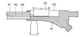
一方、本実施の形態の超音波ガイド下穿刺システム装置では、図21に示すガイドチューブコネクタ15が設けられている。
【0075】
このガイドチューブコネクタ15は、図21に示すように、その本体中央近傍にはスライダ溝53を形成し、指標スライダ52をスライダ溝53にスライド自在に取付けている。また、穿刺位置指標43は、穿刺位置指標用ルーメン42に挿通され、後端側で指標スライダ52に接続されるようになっている。
【0076】
(作用)
本実施の形態における作用は、前記第1の実施の形態と同様であり、さらに、超音波画像上で穿刺位置指標43側に病変部31が来るように調整した後、穿刺時には指標スライダ52を後端側へスライドさせることで、穿刺位置指標43をガイドチューブ41内に引っ込め、超音波画像上に写らないようにするとが可能となる。
【0077】
したがって、本実施の形態によれば、前記第1の実施の形態の超音波ガイド下穿刺システム装置と同様な効果を得られる他に、上記構成により、穿刺時には穿刺位置指標43が超音波画像上に写らなくなるため、鮮明な超音波画像を見ながら超音波ガイド下穿刺処置が可能となる。
【0078】
第6の実施の態様
図22は本発明に係る超音波ガイド下穿刺システム装置の第6の実施の態様を示し、該装置の改良が施されたガイドチューブの構成を示す断面図である。なお、図22は前記第1の実施の形態における装置と同様な構成要素には同一の符号を付して説明を省略し、異なる部分のみを説明する。
【0079】
(構成)
本実施の形態では、手元側の捻り操作に伴うガイドチューブの先端側の追従性を向上させるために、前記第1の実施の形態における超音波ガイド下穿刺システム装置のガイドチューブにおいて、その外周に沿うようにフレックスコイル45を埋設して構成したことが前記第1の実施の形態と異なる点である。
【0080】
本実施の形態の超音波ガイド下穿刺システム装置の全体構成は、前記第1の実施の形態の超音波ガイド下穿刺システム装置と略同様である。
【0081】
本実施の形態の超音波ガイド下穿刺システム装置には、図22に示すガイドチューブ44が設けられている。このガイドチューブ44は、上述したように該ガイドチューブ44の外周に沿うようにフレックスコイル45が埋設されて構成している。
【0082】
(作用)
本実施の形態における作用は、前記第1の実施の形態と同様であり、さらに、上記構成により、ガイドチューブ44は手元側の捻じり操作に対する先端側の追従性が向上することになる。
【0083】
(効果)
したがって、本実施の形態によれば、前記第1の実施の形態の超音波ガイド下穿刺システム装置と同様の効果を得られる他に、捻じり操作に対する追従性を向上させることができるため、穿刺作業時のガイドチューブ44の回転位置決め作業が容易且つ確実となり、さらに超音波ガイド下穿刺処置の作業性を向上させることが可能となる。
【0084】
第7の実施の形態
本発明の超音波ガイド下穿刺システム装置の第7の実施の形態を図4を用いて説明する。
【0085】
(構成)
本実施の形態では、さらにガイドチューブを目的部位まで挿入する際の作業性を向上させるために、前記第1の実施の形態における超音波ガイド下穿刺システム装置のガイドチューブの素材として、X線造影剤を混合した樹脂を用いて該ガイドチューブを構成したことが前記第1の実施の形態と異なる点である。
【0086】
本実施の形態の超音波ガイド下穿刺システム装置の全体構成は、前記第1の実施の形態の超音波ガイド下穿刺システム装置と略同様である。
【0087】
本実施の形態の超音波ガイド下穿刺システム装置には、図4に示すように素材としてX線造影剤を混合した樹脂を用いて構成されたガイドチューブ1aが設けられている。
【0088】
(作用)
本実施の形態における作用は、前記第1の実施の形態と同様であり、さらに、上記構成により、ガイドチューブ1aを体腔内に挿入する際、X線透視にてガイドチューブ1aの先端の位置の確認が容易に行うことが可能となる。
【0089】
(効果)
したがって、本実施の形態によれば、前記第1の実施の形態の超音波ガイド下穿刺システム装置と同様の効果を得られる他に、X線透視にてガイドチューブ1aの先端の位置の確認が容易になるため、ガイドチューブ1aを目的部位まで挿入する際の作業性を向上させることが可能となる。
【0090】
第8の実施の形態
本発明に係る超音波ガイド下穿刺システム装置の第8の実施の形態について、図23を用いて説明する。なお、説明を簡略化するため、前記第1の実施の形態における装置と異なる部分のみ説明する。
【0091】
(構成)
本実施の形態では、前記第1の実施の形態における超音波ガイド下穿刺システム装置のガイドチューブ46の先端部分に改良を施したことが前記第1の実施の形態とは異なる点である。
【0092】
本実施の形態の超音波ガイド下穿刺システム装置の全体構成は、前記第1の実施の形態の超音波ガイド下穿刺システム装置と略同様である。
【0093】
本実施の形態の超音波ガイド下穿刺システム装置には、図23に示すガイドチューブ46が設けられ、該ガイドチューブ46は、同図に示すように、マルチルーメンチューブ47の先端に先端チップ48が固定されるようになっている。この先端チップ48は、ステンレス等X線不透過な素材で構成されており、ルーメン2,ルーメン3にそれぞれに対応するルーメンを備えている。この場合、ルーメン3と連通しているルーメンには、前記第1の実施の形態と同様に曲率7を設けて構成される。
【0094】
(作用)
本実施の形態における作用は、前記第7の実施の形態と同様である。
【0095】
(効果)
したがって、本実施の形態によれば、前記第7の実施の形態の超音波ガイド下穿刺システム装置と同様な効果を得られ、つまり、ガイドチューブ46を目的部位まで挿入する際の作業性を向上させることが可能となる。
【0096】
第9実施の形態
図24は本発明に係る超音波ガイド下穿刺システム装置の第9の実施の形態を示し、該装置のガイドチューブの構成を示す斜視図である。なお、図24は前記第1の実施形態における装置と同様な構成要素には同一の符号を付して説明を省略し、異なる部分のみを説明する。
【0097】
(構成)
本実施の形態では、ガイドチューブの外径をより細く形成可能としてより超音波ガイド下穿刺処置を効果的に行うために、前記第1の実施の形態における超音波ガイド下穿刺システム装置のガイドチューブを改良したことが前記第1の実施の形態と異なる点である。
【0098】
本実施の形態の超音波ガイド下穿刺システム装置の全体構成は、前記第1の実施の形態の超音波ガイド下穿刺システム装置と略同様である。
【0099】
本実施の形態の超音波ガイド下穿刺システム装置には、図24に示すガイドチューブ49が設けられている。
【0100】
このガイドチューブ49は、前記第1の実施の形態にて内装されたルーメン3が、該ガイドチューブ49先端側でルーメン2を螺旋状に取り巻くように構成することで曲率7を形成している。
【0101】
(作用)
本実施の形態における作用は、前記第1の実施の形態と同様であり、さらに上記構成により、ガイドチューブ49の径方向にデッドスペースを設けることなくルーメン3の先端付近に曲率7を設けることができるため、ガイドチューブ49を比較的細く構成することが可能となる。
【0102】
(効果)
したがって、本実施の形態によれば、前記第1の実施の形態の超音波ガイド下穿刺システム装置と同様の効果を得られる他に、ガイドチューブ49の外径をより細く構成することが可能であるため、より末梢側の気管支や高度の狭窄部位等でも安全に且つ確実に超音波ガイド下穿刺処置を行うことが可能となる。
【0103】
[付記]
(付記項1) 細長い挿入部の先端に超音波振動子を有する超音波プローブと、穿刺針と、前記超音波プローブ及び前記穿刺針が挿通可能な少なくとも2つの第1,第2のルーメンを有するガイドチューブとを含んで構成された超音波ガイド下穿刺システム装置において、
前記穿刺針は、その先端部近傍が略一定の曲率の曲り癖を有して構成され、前記ガイドチューブの前記穿刺針が挿通される第1のルーメンの先端側開口部付近は、該ルーメンの中心軸が弧となるような略一定の曲率を有して構成されたことを特徴とする超音波ガイド下穿刺システム装置。
【0104】
(付記項2) 前記第1のルーメンの曲率は、前記ガイドチューブの先端側において第1のルーメンが前記超音波プローブが挿通される第2のルーメンからガイドチューブ外側に向けて離れていくような曲率で構成されたことを特徴とする付記項1記載の超音波ガイド下穿刺システム装置。
【0105】
(付記項3) 前記第2のルーメンは、前記超音波プローブが進退可能に構成されたことを特徴とする付記項1又は付記項2に記載の超音波ガイド下穿刺システム装置。
【0106】
(付記項4) 前記第2のルーメンは、前記第1のルーメンより先端側に延在するように構成されたことを特徴とする付記項1乃至付記項3の何れか一つに記載の超音波ガイド下穿刺システム装置。
【0107】
(付記項5) 前記穿刺針の曲り癖の曲率と前記第1のルーメンの曲率とが略一致するように構成したことを特徴とする付記項1乃至付記項4の何れか一つに記載の超音波ガイド下穿刺システム装置。
【0108】
(付記項6) 前記ガイドチューブは、その外径が4mm以下に構成されたことを特徴とする付記項1乃至付記項5の何れか一つに記載の超音波ガイド下穿刺システム装置。
【0109】
【発明の効果】
以上説明したように本発明によれば、抹消気管支、膵管・胆管などの深部部位においても、超音波ガイド下穿刺処置を安全且つ確実に行うことができる。
【図面の簡単な説明】
【図1】 本発明の超音波ガイド下穿刺システム装置の第1の実施の形態を示し、該装置の全体構成を示す構成図。
【図2】 超音波ガイド下穿刺システム装置の先端部の構成を示す断面図。
【図3】 穿刺針の構成を示す構成図。
【図4】 ガイドチューブ先端部の構成を示す断面図。
【図5】 超音波プローブの構成を示す構成図。
【図6】 手元操作部の構成を示す構成図。
【図7】 ガイドチューブコネクタの構成を示す断面図。
【図8】 穿刺用ハンドルの構成を示す断面図。
【図9】 穿刺針挿入用スタイレットの構成を示す構成図。
【図10】 穿刺針挿入用ガードの構成を示す構成図。
【図11】 超音波ガイド下穿刺システム装置の主要動作を説明するための説明図。
【図12】 穿刺用ハンドル動作を説明するための説明図。
【図13】 ガイドチューブ先端の具体的構成を示す断面図。
【図14】 本発明の超音波ガイド下穿刺システム装置の第2の実施の形態を示し、三次元走査型用ガイドチューブ先端部の構成を示す断面図。
【図15】 三次元走査型用ガイドチューブコネクタの構成を示す断面図。
【図16】 本発明の超音波ガイド下穿刺システム装置の第3の実施の形態を示し、改良がなされた三次元走査型用ガイドチューブの構成を示す断面図。
【図17】 本発明の超音波ガイド下穿刺システム装置の第4の実施の形態を示し、該装置に設けられた超音波プローブ一体型ガイドチューブの先端部の構成を示す断面図。
【図18】 超音波プローブ一体型ガイドチューブコネクタの構成を示す断面図。
【図19】 本発明の超音波ガイド下穿刺システム装置の第5の実施の形態を示し、該装置に設けられたガイドチューブの構成を示す断面図。
【図20】 図19のガイドチューブの上面図。
【図21】 ガイドチューブコネクタの構成を示す断面図。
【図22】 本発明の超音波ガイド下穿刺システム装置の第6の実施の形態を示し、該装置の改良されたガイドチューブの構成を示す断面図。
【図23】 本発明の超音波ガイド下穿刺システム装置の第7及び第8の実施の形態を示し、該装置の改良が施されたガイドチューブの構成を示す断面図。
【図24】 本発明の超音波ガイド穿刺システム装置の第9の実施の形態を示し、該装置のガイドチューブの構成を示す斜視図。[0001]
BACKGROUND OF THE INVENTION
The present invention relates to an ultrasound-guided puncture system apparatus that guides and punctures a puncture needle under an ultrasound image in a deep luminal organ such as a peripheral bronchus, pancreatic duct, or bile duct.
[0002]
[Prior art]
In recent years, puncture using an ultrasound guide for obtaining a definitive diagnosis such as judgment of benign malignancy of a tumor has attracted attention. In particular, recently, an ultrasonic probe capable of scanning the front or side is provided at the distal end of an endoscope, and a puncture needle that can project a puncture needle protruding from a forceps channel of an endoscope on an ultrasonic image Ultrasound endoscopes have been proposed, and ultrasonically guided puncture from inside the body cavity has also become possible.
[0003]
As such an ultrasonic endoscope that can be punctured under ultrasonic waves, there is an ultrasonic endoscope proposed by, for example, Japanese Patent Laid-Open No. 6-105847. In the ultrasonic endoscope according to this proposal, an ultrasonic transmission / reception unit, a lead-out port through which the puncture needle is punctured in an inspection direction by the ultrasonic reception unit, and an observation for observing the puncture needle derived from the lead-out port In the endoscope provided with the optical window and the distal end configuration part of the living body insertion part, the ultrasonic transmission / reception means, the outlet, and the observation optical window are arranged on the same line in the longitudinal direction of the living body insertion part. It is said.
[0004]
According to such a configuration, since the ultrasonic transmission / reception means, the outlet, and the observation optical window are arranged on the same line in the longitudinal direction of the living body insertion portion, the ultrasonic wave is centered on the image observed from the observation optical window. The center of the tomographic image coincides with the lead-out direction of the puncture needle, so that the puncture needle can be visually observed from the front, and the treatment with the puncture needle can be easily performed accurately.
[0005]
[Problems to be solved by the invention]
However, in the conventional ultrasonic endoscope proposed in Japanese Patent Laid-Open No. 6-105847 described above, the insertion portion of the puncture ultrasonic endoscope is configured with a diameter of 10 mm or more. It cannot be inserted into narrow lumens such as bronchi, pancreatic duct, bile duct, altitude or stenosis. In addition, a small-diameter ultrasonic probe for performing an intracorporeal ultrasonic examination through the forceps channel of the endoscope can be inserted into these parts, but it is very difficult to guide the puncture. There was also a problem.
[0006]
Therefore, the present invention has been made in view of the above problems, and ultrasonic waves are also applied to deep sites such as an applied bronchus, pancreatic duct and bile duct.guideAn object of the present invention is to provide an ultrasonic guided puncture system apparatus capable of safely and reliably performing a lower puncture treatment, and a guide tube for the apparatus.
[0007]
The ultrasonic-guided puncture system apparatus according to the present invention includes an ultrasonic probe having an ultrasonic transducer on the distal end side of an elongated insertion portion, a puncture needle, and at least two second probes through which the ultrasonic probe and the puncture needle can be inserted. An ultrasonic guided puncture system device comprising a guide tube having a first lumen and a second lumen,
The puncture needle is configured to have a curved rod having a substantially constant curvature near the distal end portion thereof, and the vicinity of the distal end side opening portion of the second lumen through which the puncture needle of the guide tube is inserted is provided in the lumen. It has a substantially constant curvature so that the central axis is an arc.At the same time, a convex puncture position index is provided between the openings of the first lumen and the second lumen at the tip of the guide tube.
Moreover, the guide tube for an ultrasonic guided puncture system apparatus of the present invention includes a first lumen for inserting an ultrasonic probe having an ultrasonic transducer on the distal end side of an elongated insertion portion, and a second lumen for inserting a puncture needle. An arcuate shape that is formed in an elongated shape so that it can be inserted into a body cavity, and is gradually separated from the first lumen toward the distal end near the distal end of the second lumen through which the puncture needle is inserted. In addition, a convex puncture position index is provided between the opening portions of the first lumen and the second lumen at the tip.
[0008]
According to the present invention, the puncture needle is configured so as to have a bend with a substantially constant curvature in the vicinity of the distal end portion, and the distal end opening of the first lumen through which the puncture needle of the guide tube is inserted. Since the vicinity of the portion is configured to have a substantially constant curvature such that the central axis of the lumen forms an arc, the puncture needle can be reliably projected toward the side of the guide tube. Therefore, real-time ultrasonic guided puncture treatment from the body cavity can be performed also in the peripheral bronchus, pancreatic duct, bile duct and the like.
[0009]
DETAILED DESCRIPTION OF THE INVENTION
Hereinafter, embodiments of the present invention will be described with reference to the drawings.
[0010]
First embodiment:
1 to 12 show a first embodiment of an ultrasonic guided puncture system apparatus according to the present invention, FIG. 1 is a block diagram showing the overall configuration of the ultrasonic guided puncture system apparatus, and FIG. FIG. 3 is a cross-sectional view showing the configuration of the puncture needle, FIG. 4 is a cross-sectional view showing the configuration of the guide tube tip, and FIG. 5 is a block diagram showing the configuration of the ultrasonic probe. FIG. 6 is a block diagram showing the configuration of the hand operating unit, FIG. 7 is a cross-sectional view showing the configuration of the guide tube connector, FIG. 8 is a cross-sectional view showing the configuration of the puncture handle, and FIG. 9 is the configuration of the stylet for inserting the puncture needle FIG. 10 is a configuration diagram showing the configuration of the puncture needle insertion guard, FIG. 11 is an explanatory diagram for explaining the main operation of the device, and FIG. 12 is an explanatory diagram for explaining the puncture handle operation. It is.
[0011]
(Constitution)
As shown in FIG. 1, in the ultrasonic guided puncture system apparatus of the present embodiment, an
[0012]
A
[0013]
The configuration of the distal end portion of the ultrasonic guided puncture system apparatus is as shown in FIG. That is, as shown in FIG. 2, the
[0014]
The ultrasonic guided puncture system apparatus of the present invention is characterized in that the configuration of the
[0015]
As shown in FIG. 3A, the
[0016]
The material of the
[0017]
Moreover, the guide tube front-end | tip part is comprised as shown in FIG.4 and FIG.13. As shown in FIG. 4, the
Specifically, the distal end portion of the
The action of the
Therefore,This
[0018]
On the other hand, the
[0019]
As the
[0020]
Next, a configuration in the vicinity of the operation unit of the ultrasonic guided puncture system apparatus according to the present embodiment will be described.
[0021]
As shown in FIG. 6, a
[0022]
More specifically, as shown in FIG. 7, the
[0023]
As shown in FIG. 8, at the distal end side of the puncture handle
[0024]
As shown in FIG. 9, the puncture
[0025]
In this example, a puncture
[0026]
(Function)
Next, the operation will be described in detail with reference to FIG.
[0027]
Assume that an ultrasonic guided puncture treatment is performed using the ultrasonic guided puncture system apparatus of FIG. In this case, an ultrasonic-guided puncture procedure can be performed according to the procedure shown below.
[0028]
First, with the
[0029]
Then, physiological saline or the like for drawing an ultrasonic image is injected from the
[0030]
Then, the
[0031]
The protruding direction of the
[0032]
Then, the distance to the
[0033]
Thereafter, as shown in FIG. 11, the
[0034]
In this case, since the
[0035]
Thereafter, the
[0036]
At this time, if the tip of the
[0037]
When the tip of the
[0038]
After the puncture treatment, once used, the
[0039]
Further, when the puncture treatment is subsequently performed, a
[0040]
When the
[0041]
(effect)
Therefore, according to the present embodiment, it is safe to perform ultrasonic guided puncture in a narrow lumen, altitude or stenosis, etc., such as the non-bronchial bronchus, pancreatic duct, bile duct, etc. And it can be performed reliably. Moreover, since it can implement by simple improvement, it contributes also to cost reduction.
[0047]
SecondEmbodiment
14 and 15 show an ultrasonic guided puncture system apparatus according to the present invention.SecondFIG. 14 is a cross-sectional view showing the configuration of the guide tube tip when configured as a three-dimensional scanning ultrasonic guided puncture system device, and FIG. 15 is a guide tube configured according to the device. It is sectional drawing which shows the structure of a connector. 14 and 15, the same components as those in the first embodiment are denoted by the same reference numerals, description thereof is omitted, and only different portions are described.
[0048]
(Constitution)
In the present embodiment, by providing the guide tube tip and guide tube connector improved for the three-dimensional scanning type, the ultrasonic guided puncture system apparatus in the first embodiment is changed to the three-dimensional scanning type The difference from the above embodiment is that it is configured as a sonic guided puncture system device.
[0049]
The overall configuration of the three-dimensional scanning ultrasonic guided puncture system apparatus is substantially the same as that of the ultrasonic guided puncture system apparatus of the first embodiment.
[0050]
In the three-dimensional scanning ultrasonic guided puncture system apparatus of the present embodiment, a three-dimensional
[0051]
As shown in FIG. 14, the three-dimensional
[0052]
On the other hand, in the three-dimensional scanning guide tube connector, as shown in FIG. 15, an outer
[0053]
(Function)
The operation in the present embodiment is the same as that of the first embodiment. Furthermore, since the
[0054]
(effect)
Therefore, according to this embodiment, in addition to obtaining the same effect as the ultrasonic guided puncture system apparatus of the first embodiment, it is possible to perform three-dimensional scanning with a simple configuration. Since the relationship between the
[0055]
ThirdEmbodiment
FIG. 16 shows an ultrasonic guided puncture system apparatus according to the present invention.ThirdIt is sectional drawing which shows embodiment and shows the structure of the guide tube in which the improvement at the time of comprising as a three-dimensional scanning ultrasonic guided puncture system apparatus was made | formed. Note that FIG.SecondConstituent elements similar to those of the apparatus in the embodiment are denoted by the same reference numerals, description thereof is omitted, and only different portions are described.
[0056]
In the present embodiment, theSecondThe three-dimensional scanning ultrasonic guided puncture system apparatus according to the embodiment is characterized in that the projection direction of the
[0057]
The overall configuration of the three-dimensional scanning ultrasonic guided puncture system device of the present embodiment isSecondAlthough substantially the same as the ultrasonic guided puncture system apparatus of the embodiment, the three-dimensional
[0058]
Specifically, as shown in FIG. 16, in the three-dimensional
[0059]
(Function)
The operation in the present embodiment is as described above.SecondFurther, the puncture needle is adjusted by adjusting the rotational position of the
[0060]
Therefore, according to the present embodiment,SecondIn addition to obtaining the same effects as those of the three-dimensional scanning ultrasonic guided puncture system apparatus according to the embodiment, the above-described operation makes it possible to easily and reliably grasp the protruding direction of the
[0061]
4thEmbodiment
17 and 18 show an ultrasonic guided puncture system apparatus according to the present invention.4thFIG. 17 is a cross-sectional view showing the configuration of the distal end portion of an ultrasonic probe integrated guide tube provided in the three-dimensional scanning ultrasonic guided puncture system apparatus, and FIG. 18 is an ultrasonic probe integrated type. It is sectional drawing which shows the structure of a guide tube connector. 17 and 18 are the same as those described above.SecondConstituent elements similar to those of the apparatus in the embodiment are denoted by the same reference numerals, description thereof is omitted, and only different portions will be described.
[0062]
In the present embodiment, the aboveSecondThe guide tube distal end portion of the three-dimensional scanning ultrasonic guided puncture system apparatus according to the embodiment can be formed with a thinner outer diameter of the guide tube, and the ultrasonic guided puncture treatment can be performed more effectively. It is the feature that improved for.
[0063]
The overall configuration of the three-dimensional scanning ultrasonic guided puncture system apparatus according to the present embodiment is substantially the same as that of the ultrasonic guided puncture system apparatus according to the third embodiment. An acoustic probe integrated guide tube is employed.
[0064]
Specifically, as shown in FIG. 17, the ultrasonic probe integrated
[0065]
Further, by adopting the above-described ultrasonic probe integrated
[0066]
In this ultrasonic probe-integrated guide tube connector, as shown in FIG. 18, a
[0067]
(Function)
The operation in the present embodiment is as described above.SecondThe outer diameter of the
[0068]
Therefore, according to the present embodiment,SecondIn addition to obtaining the same effect as that of the three-dimensional scanning ultrasonic guided puncture system apparatus of the embodiment, the outer diameter of the
[0069]
5thEmbodiment
19 to 21 show an ultrasonic guided puncture system apparatus according to the present invention.5th19 is a cross-sectional view showing the configuration of a guide tube provided in the apparatus, FIG. 20 is a top view of the guide tube, and FIG. 21 shows the configuration of a guide tube connector provided in the apparatus. It is sectional drawing shown. 19 to 21 are the same as those shown in FIG.FirstConstituent elements similar to those of the apparatus in the embodiment are denoted by the same reference numerals, description thereof is omitted, and only different portions will be described.
[0070]
(Constitution)
In this embodiment, in order to perform an ultrasound-guided puncture procedure while viewing a clearer ultrasound image,FirstIn place of the puncture position index 35 (see FIG. 13), another
[0071]
The overall configuration of the ultrasound guided puncture system apparatus of the present embodiment is substantially the same as the ultrasound guided puncture system apparatus of the second embodiment.
[0072]
The ultrasonic guided puncture system apparatus according to the present embodiment is provided with a
[0073]
Further, as shown in FIG. 20, a U-shaped
[0074]
On the other hand, in the ultrasonic guided puncture system apparatus of the present embodiment, a
[0075]
As shown in FIG. 21, the
[0076]
(Function)
The operation in the present embodiment is as described above.FirstFurther, after adjusting so that the
[0077]
Therefore, according to the present embodiment,FirstIn addition to obtaining the same effect as the ultrasonic guided puncture system apparatus of the above embodiment, the
[0078]
6thEmbodiments of
FIG. 22 shows an ultrasonic guided puncture system apparatus according to the present invention.6thIt is sectional drawing which shows the aspect of this and shows the structure of the guide tube by which improvement of this apparatus was given. In FIG. 22, the same components as those in the first embodiment are denoted by the same reference numerals, description thereof is omitted, and only different portions are described.
[0079]
(Constitution)
In the present embodiment, in order to improve the followability on the distal end side of the guide tube accompanying the twisting operation on the hand side, in the guide tube of the ultrasonic guided puncture system device in the first embodiment, The difference from the first embodiment is that the
[0080]
The overall configuration of the ultrasound-guided puncture system apparatus of the present embodiment is substantially the same as that of the ultrasound-guided puncture system apparatus of the first embodiment.
[0081]
The ultrasonic guided puncture system apparatus according to the present embodiment is provided with a
[0082]
(Action)
The operation in the present embodiment is the same as that in the first embodiment, and the
[0083]
(effect)
Therefore, according to the present embodiment, in addition to obtaining the same effect as the ultrasonic guided puncture system apparatus of the first embodiment, it is possible to improve the followability to the twisting operation. The rotation positioning operation of the
[0084]
7thEmbodiment
The ultrasonic guided puncture system apparatus of the present invention7thThe embodiment will be described with reference to FIG.
[0085]
(Constitution)
In this embodiment, in order to further improve workability when the guide tube is inserted to the target site, X-ray contrast imaging is used as the material of the guide tube of the ultrasonic guided puncture system apparatus in the first embodiment. The difference from the first embodiment is that the guide tube is configured using a resin mixed with an agent.
[0086]
The overall configuration of the ultrasound-guided puncture system apparatus of the present embodiment is substantially the same as that of the ultrasound-guided puncture system apparatus of the first embodiment.
[0087]
As shown in FIG. 4, the ultrasound guided puncture system apparatus of the present embodiment is provided with a guide tube 1a configured using a resin mixed with an X-ray contrast medium as a material.
[0088]
(Function)
The operation in the present embodiment is the same as that in the first embodiment. Further, with the above configuration, when the guide tube 1a is inserted into the body cavity, the position of the tip of the guide tube 1a is determined by X-ray fluoroscopy. Confirmation can be easily performed.
[0089]
(effect)
Therefore, according to the present embodiment, in addition to obtaining the same effect as the ultrasonic guided puncture system apparatus of the first embodiment, the position of the tip of the guide tube 1a can be confirmed by X-ray fluoroscopy. Since it becomes easy, it becomes possible to improve workability | operativity at the time of inserting the guide tube 1a to the target site | part.
[0090]
8thEmbodiment
An ultrasonic guided puncture system apparatus according to the present invention8thThis embodiment will be described with reference to FIG. In order to simplify the description, only parts different from the apparatus in the first embodiment will be described.
[0091]
(Constitution)
The present embodiment is different from the first embodiment in that the distal end portion of the
[0092]
The overall configuration of the ultrasound-guided puncture system apparatus of the present embodiment is substantially the same as that of the ultrasound-guided puncture system apparatus of the first embodiment.
[0093]
The ultrasonic guided puncture system apparatus according to the present embodiment is provided with a
[0094]
(Function)
The operation in the present embodiment is as described above.7thThis is the same as the embodiment.
[0095]
(effect)
Therefore, according to the present embodiment,7thThe same effect as the ultrasonic guided puncture system apparatus of the embodiment can be obtained, that is, the workability when the
[0096]
9thEmbodiment
FIG. 24 shows an ultrasonic guided puncture system apparatus according to the present invention.9thIt is a perspective view which shows this embodiment and shows the structure of the guide tube of this apparatus. In FIG. 24, the same components as those in the apparatus in the first embodiment are denoted by the same reference numerals, description thereof is omitted, and only different portions will be described.
[0097]
(Constitution)
In the present embodiment, the guide tube of the ultrasonic guided puncture system apparatus according to the first embodiment may be used to make the outer diameter of the guide tube thinner and more effectively perform an ultrasonic guided puncture treatment. The improvement is different from the first embodiment.
[0098]
The overall configuration of the ultrasound-guided puncture system apparatus of the present embodiment is substantially the same as that of the ultrasound-guided puncture system apparatus of the first embodiment.
[0099]
The ultrasound guided puncture system apparatus according to the present embodiment is provided with a
[0100]
The
[0101]
(Function)
The operation in the present embodiment is the same as that in the first embodiment. Further, with the above configuration, the
[0102]
(effect)
Therefore, according to this embodiment, in addition to obtaining the same effect as the ultrasonic guided puncture system apparatus of the first embodiment, it is possible to make the outer diameter of the
[0103]
[Appendix]
(Additional Item 1) An ultrasonic probe having an ultrasonic transducer at the tip of an elongated insertion portion, a puncture needle, and at least two first and second lumens through which the ultrasonic probe and the puncture needle can be inserted. In an ultrasonic guided puncture system device configured to include a guide tube,
The puncture needle is configured so that the vicinity of the distal end thereof has a curved surface having a substantially constant curvature, and the vicinity of the opening on the distal end side of the first lumen through which the puncture needle of the guide tube is inserted is An ultrasonic guided puncture system apparatus having a substantially constant curvature such that a central axis is an arc.
[0104]
(Additional Item 2) The curvature of the first lumen is such that the first lumen moves away from the second lumen through which the ultrasonic probe is inserted toward the outside of the guide tube on the distal end side of the guide tube. The ultrasonic guided puncture system device according to
[0105]
(Additional Item 3) The ultrasonic guided puncture system apparatus according to
[0106]
(Additional Item 4) The superstructure according to any one of
[0107]
(Additional Item 5) According to any one of
[0108]
(Additional Item 6) The ultrasonic guided puncture system apparatus according to any one of
[0109]
【The invention's effect】
As described above, according to the present invention, ultrasonic waves are also obtained in deep sites such as peripheral bronchi, pancreatic ducts and bile ducts.guideThe lower puncture procedure can be performed safely and reliably.
[Brief description of the drawings]
FIG. 1 is a configuration diagram showing a first embodiment of an ultrasonic guided puncture system apparatus according to the present invention and showing an overall configuration of the apparatus.
FIG. 2 is a cross-sectional view showing a configuration of a distal end portion of an ultrasonic guided puncture system apparatus.
FIG. 3 is a configuration diagram showing a configuration of a puncture needle.
FIG. 4 is a cross-sectional view showing the configuration of the guide tube tip.
FIG. 5 is a configuration diagram showing a configuration of an ultrasonic probe.
FIG. 6 is a configuration diagram showing a configuration of a hand operation unit.
FIG. 7 is a cross-sectional view showing a configuration of a guide tube connector.
FIG. 8 is a cross-sectional view showing a configuration of a puncture handle.
FIG. 9 is a configuration diagram showing a configuration of a puncture needle insertion stylet.
FIG. 10 is a configuration diagram showing a configuration of a puncture needle insertion guard.
FIG. 11 is an explanatory diagram for explaining the main operation of the ultrasound guided puncture system apparatus.
FIG. 12 is an explanatory diagram for explaining the puncture handle operation.
FIG. 13GaSectional drawing which shows the specific structure of the id tube tip.
FIG. 14 shows an ultrasonic guided puncture system apparatus according to the present invention.SecondSectional drawing which shows this embodiment and shows the structure of the guide tube front-end | tip part for three-dimensional scanning types.
FIG. 15 is a cross-sectional view showing a configuration of a three-dimensional scanning guide tube connector.
FIG. 16 shows an ultrasonic guided puncture system apparatus according to the present invention.ThirdSectional drawing which shows embodiment of this and shows the structure of the guide tube for three-dimensional scanning type by which improvement was made | formed.
FIG. 17 shows an ultrasonic guided puncture system apparatus according to the present invention.4thSectional drawing which shows this embodiment and shows the structure of the front-end | tip part of the ultrasonic probe integrated guide tube provided in this apparatus.
FIG. 18 is a cross-sectional view showing the configuration of an ultrasonic probe integrated guide tube connector.
FIG. 19 shows an ultrasonic guided puncture system apparatus according to the present invention.5thSectional drawing which shows embodiment of this and shows the structure of the guide tube provided in this apparatus.
20 is a top view of the guide tube of FIG.
FIG. 21 is a cross-sectional view showing a configuration of a guide tube connector.
FIG. 22 shows an ultrasonic guided puncture system apparatus according to the present invention.6thSectional drawing which shows embodiment of this and shows the structure of the improved guide tube of this apparatus.
FIG. 23 shows an ultrasonic guided puncture system apparatus according to the present invention.7th and 8thSectional drawing which shows embodiment of this and shows the structure of the guide tube by which improvement of this apparatus was given.
FIG. 24 shows an ultrasonic guided puncture system apparatus according to the present invention.9thThe perspective view which shows embodiment of this and shows the structure of the guide tube of this apparatus.
Claims (5)
前記穿刺針は、その先端部近傍が略一定の曲率の曲がり癖を有して構成され、前記ガイドチューブの前記穿刺針が挿通される第2のルーメンの先端側開口部付近は、該ルーメンの中心軸が弧となるような略一定の曲率を有して構成されていると共に、前記ガイドチューブ先端の前記第1のルーメンと第2のルーメンとの開口部の間に凸状の穿刺位置指標を設けたことを特徴とする超音波ガイド下穿刺システム装置。An ultrasonic probe having an ultrasonic transducer on the distal end side of the elongated insertion portion, a puncture needle, and a guide tube having at least two first and second lumens through which the ultrasonic probe and the puncture needle can be inserted. In an ultrasonic guided puncture system device comprising:
The puncture needle is configured to have a curved rod having a substantially constant curvature near the distal end portion thereof, and the vicinity of the distal end side opening portion of the second lumen through which the puncture needle of the guide tube is inserted is provided in the lumen. A puncture position index having a substantially constant curvature such that the central axis forms an arc and a convex puncture position index between openings of the first lumen and the second lumen at the tip of the guide tube An ultrasonic-guided puncture system device comprising:
Priority Applications (1)
| Application Number | Priority Date | Filing Date | Title |
|---|---|---|---|
| JP28863399A JP4363719B2 (en) | 1999-10-08 | 1999-10-08 | Ultrasound-guided puncture system device |
Applications Claiming Priority (1)
| Application Number | Priority Date | Filing Date | Title |
|---|---|---|---|
| JP28863399A JP4363719B2 (en) | 1999-10-08 | 1999-10-08 | Ultrasound-guided puncture system device |
Publications (3)
| Publication Number | Publication Date |
|---|---|
| JP2001104315A JP2001104315A (en) | 2001-04-17 |
| JP2001104315A5 JP2001104315A5 (en) | 2006-11-16 |
| JP4363719B2 true JP4363719B2 (en) | 2009-11-11 |
Family
ID=17732705
Family Applications (1)
| Application Number | Title | Priority Date | Filing Date |
|---|---|---|---|
| JP28863399A Expired - Fee Related JP4363719B2 (en) | 1999-10-08 | 1999-10-08 | Ultrasound-guided puncture system device |
Country Status (1)
| Country | Link |
|---|---|
| JP (1) | JP4363719B2 (en) |
Cited By (2)
| Publication number | Priority date | Publication date | Assignee | Title |
|---|---|---|---|---|
| CN107920811A (en) * | 2015-09-01 | 2018-04-17 | 波士顿科学国际有限公司 | INod handles on scope |
| CN110035685A (en) * | 2016-12-07 | 2019-07-19 | 波士顿科学国际有限公司 | The system and method for eccentric Nodule tissue acquisition |
Families Citing this family (74)
| Publication number | Priority date | Publication date | Assignee | Title |
|---|---|---|---|---|
| US6712812B2 (en) | 1999-08-05 | 2004-03-30 | Broncus Technologies, Inc. | Devices for creating collateral channels |
| EP1400204A1 (en) | 1999-08-05 | 2004-03-24 | Broncus Technologies, Inc. | Methods and devices for creating collateral channels in the lungs |
| US6749606B2 (en) | 1999-08-05 | 2004-06-15 | Thomas Keast | Devices for creating collateral channels |
| JP4475842B2 (en) * | 2001-04-18 | 2010-06-09 | Hoya株式会社 | Endoscopic puncture device |
| JP3805652B2 (en) * | 2001-08-02 | 2006-08-02 | オリンパス株式会社 | Endoscopic forceps adapter |
| US7708712B2 (en) | 2001-09-04 | 2010-05-04 | Broncus Technologies, Inc. | Methods and devices for maintaining patency of surgically created channels in a body organ |
| JP4339539B2 (en) * | 2001-12-27 | 2009-10-07 | オリンパス株式会社 | Ultrasound puncture needle |
| US20040193034A1 (en) * | 2003-03-28 | 2004-09-30 | Lawrence Wasicek | Combined long rail/short rail IVUS catheter |
| US8308682B2 (en) | 2003-07-18 | 2012-11-13 | Broncus Medical Inc. | Devices for maintaining patency of surgically created channels in tissue |
| JP4370147B2 (en) * | 2003-11-10 | 2009-11-25 | オリンパス株式会社 | Ultrasound puncture needle |
| JP4614265B2 (en) * | 2004-05-06 | 2011-01-19 | 朝日インテック株式会社 | In vivo observation catheter |
| JP4995720B2 (en) | 2004-07-02 | 2012-08-08 | ザ ジェネラル ホスピタル コーポレイション | Endoscopic imaging probe with double clad fiber |
| US8409167B2 (en) | 2004-07-19 | 2013-04-02 | Broncus Medical Inc | Devices for delivering substances through an extra-anatomic opening created in an airway |
| US8208995B2 (en) * | 2004-08-24 | 2012-06-26 | The General Hospital Corporation | Method and apparatus for imaging of vessel segments |
| JP4596530B2 (en) * | 2005-03-10 | 2010-12-08 | フィルメック株式会社 | Medical treatment tool |
| EP2085929A1 (en) | 2005-04-28 | 2009-08-05 | The General Hospital Corporation | Evaluating optical coherence tomography information for an anatomical structure |
| WO2007084903A2 (en) | 2006-01-19 | 2007-07-26 | The General Hospital Corporation | Apparatus for obtaining information for a structure using spectrally-encoded endoscopy techniques and method for producing one or more optical arrangements |
| US7538859B2 (en) | 2006-02-01 | 2009-05-26 | The General Hospital Corporation | Methods and systems for monitoring and obtaining information of at least one portion of a sample using conformal laser therapy procedures, and providing electromagnetic radiation thereto |
| EP1983921B1 (en) | 2006-02-01 | 2016-05-25 | The General Hospital Corporation | Systems for providing electromagnetic radiation to at least one portion of a sample using conformal laser therapy procedures |
| WO2007101026A2 (en) | 2006-02-24 | 2007-09-07 | The General Hospital Corporation | Methods and systems for performing angle-resolved fourier-domain optical coherence tomography |
| US8838213B2 (en) | 2006-10-19 | 2014-09-16 | The General Hospital Corporation | Apparatus and method for obtaining and providing imaging information associated with at least one portion of a sample, and effecting such portion(s) |
| US9421071B2 (en) | 2006-12-01 | 2016-08-23 | Boston Scientific Scimed, Inc. | Direct drive methods |
| WO2008144077A1 (en) | 2007-05-18 | 2008-11-27 | Boston Scientific Scimed, Inc. | Drive systems and methods of use |
| WO2010009136A2 (en) | 2008-07-14 | 2010-01-21 | The General Hospital Corporation | Apparatus and methods for color endoscopy |
| WO2010021951A2 (en) * | 2008-08-18 | 2010-02-25 | The Brigham And Women's Hospital, Inc. | Integrated surgical sampling probe |
| US9615748B2 (en) | 2009-01-20 | 2017-04-11 | The General Hospital Corporation | Endoscopic biopsy apparatus, system and method |
| WO2011004820A1 (en) * | 2009-07-06 | 2011-01-13 | 国立大学法人大阪大学 | Endoscope overtube |
| BR112012001042A2 (en) | 2009-07-14 | 2016-11-22 | Gen Hospital Corp | fluid flow measurement equipment and method within anatomical structure. |
| JP5797195B2 (en) * | 2009-07-23 | 2015-10-21 | ケンドール、 アール. ウォーターズ、 | Intraventricular infusion catheter system with integrated echocardiography capability |
| JP2011036301A (en) * | 2009-08-07 | 2011-02-24 | Masataka Funada | Endoscope |
| JP2011078682A (en) * | 2009-10-09 | 2011-04-21 | Masataka Funada | Puncture needle |
| DK2542154T3 (en) | 2010-03-05 | 2020-11-23 | Massachusetts Gen Hospital | APPARATUS FOR PROVIDING ELECTROMAGNETIC RADIATION TO A SAMPLE |
| US9069130B2 (en) | 2010-05-03 | 2015-06-30 | The General Hospital Corporation | Apparatus, method and system for generating optical radiation from biological gain media |
| EP2575597B1 (en) | 2010-05-25 | 2022-05-04 | The General Hospital Corporation | Apparatus for providing optical imaging of structures and compositions |
| WO2011150069A2 (en) | 2010-05-25 | 2011-12-01 | The General Hospital Corporation | Apparatus, systems, methods and computer-accessible medium for spectral analysis of optical coherence tomography images |
| US10285568B2 (en) | 2010-06-03 | 2019-05-14 | The General Hospital Corporation | Apparatus and method for devices for imaging structures in or at one or more luminal organs |
| JP2012040078A (en) * | 2010-08-16 | 2012-03-01 | Masataka Funada | Endoscope |
| JP5883018B2 (en) | 2010-10-27 | 2016-03-09 | ザ ジェネラル ホスピタル コーポレイション | Apparatus, system, and method for measuring blood pressure within at least one blood vessel |
| US8709034B2 (en) | 2011-05-13 | 2014-04-29 | Broncus Medical Inc. | Methods and devices for diagnosing, monitoring, or treating medical conditions through an opening through an airway wall |
| JP2014521381A (en) | 2011-05-13 | 2014-08-28 | ブロンカス テクノロジーズ, インコーポレイテッド | Methods and devices for tissue ablation |
| US9330092B2 (en) | 2011-07-19 | 2016-05-03 | The General Hospital Corporation | Systems, methods, apparatus and computer-accessible-medium for providing polarization-mode dispersion compensation in optical coherence tomography |
| EP2769491A4 (en) | 2011-10-18 | 2015-07-22 | Gen Hospital Corp | Apparatus and methods for producing and/or providing recirculating optical delay(s) |
| WO2013078235A1 (en) | 2011-11-23 | 2013-05-30 | Broncus Medical Inc | Methods and devices for diagnosing, monitoring, or treating medical conditions through an opening through an airway wall |
| US20130225997A1 (en) * | 2012-02-28 | 2013-08-29 | Spiration, Inc. | Lung biopsy needle |
| WO2013148306A1 (en) | 2012-03-30 | 2013-10-03 | The General Hospital Corporation | Imaging system, method and distal attachment for multidirectional field of view endoscopy |
| US11490797B2 (en) | 2012-05-21 | 2022-11-08 | The General Hospital Corporation | Apparatus, device and method for capsule microscopy |
| WO2014013589A1 (en) * | 2012-07-19 | 2014-01-23 | テルモ株式会社 | Puncture device |
| WO2014031748A1 (en) | 2012-08-22 | 2014-02-27 | The General Hospital Corporation | System, method, and computer-accessible medium for fabrication minature endoscope using soft lithography |
| US9968261B2 (en) | 2013-01-28 | 2018-05-15 | The General Hospital Corporation | Apparatus and method for providing diffuse spectroscopy co-registered with optical frequency domain imaging |
| US10893806B2 (en) | 2013-01-29 | 2021-01-19 | The General Hospital Corporation | Apparatus, systems and methods for providing information regarding the aortic valve |
| WO2014121082A1 (en) | 2013-02-01 | 2014-08-07 | The General Hospital Corporation | Objective lens arrangement for confocal endomicroscopy |
| US10478072B2 (en) | 2013-03-15 | 2019-11-19 | The General Hospital Corporation | Methods and system for characterizing an object |
| WO2014186353A1 (en) | 2013-05-13 | 2014-11-20 | The General Hospital Corporation | Detecting self-interefering fluorescence phase and amplitude |
| US11452433B2 (en) | 2013-07-19 | 2022-09-27 | The General Hospital Corporation | Imaging apparatus and method which utilizes multidirectional field of view endoscopy |
| WO2015010133A1 (en) | 2013-07-19 | 2015-01-22 | The General Hospital Corporation | Determining eye motion by imaging retina. with feedback |
| ES2893237T3 (en) | 2013-07-26 | 2022-02-08 | Massachusetts Gen Hospital | Apparatus with a laser arrangement using optical scattering for applications in optical coherence tomography in the Fourier domain |
| WO2015105870A1 (en) | 2014-01-08 | 2015-07-16 | The General Hospital Corporation | Method and apparatus for microscopic imaging |
| US10736494B2 (en) | 2014-01-31 | 2020-08-11 | The General Hospital Corporation | System and method for facilitating manual and/or automatic volumetric imaging with real-time tension or force feedback using a tethered imaging device |
| US10228556B2 (en) | 2014-04-04 | 2019-03-12 | The General Hospital Corporation | Apparatus and method for controlling propagation and/or transmission of electromagnetic radiation in flexible waveguide(s) |
| EP3171766B1 (en) | 2014-07-25 | 2021-12-29 | The General Hospital Corporation | Apparatus for in vivo imaging and diagnosis |
| DE112014007043T5 (en) * | 2014-11-26 | 2017-08-10 | Olympus Corporation | Endoscope sheath and endoscope injection positioning device |
| JP2015142738A (en) * | 2015-02-03 | 2015-08-06 | 株式会社エム・ピー・アイ | multi-lumen tube for endoscope |
| WO2017094182A1 (en) * | 2015-12-04 | 2017-06-08 | オリンパス株式会社 | Overtube |
| JP2017176465A (en) * | 2016-03-30 | 2017-10-05 | オリンパス株式会社 | Ultrasound observation apparatus, operation method for ultrasound observation apparatus, and operation program for ultrasound observation apparatus |
| US11633176B2 (en) | 2016-08-03 | 2023-04-25 | Boston Scientific Scimed Inc. | Positioning devices, methods, and systems |
| WO2018157038A1 (en) * | 2017-02-27 | 2018-08-30 | Boston Scientific Scimed, Inc. | Systems for body passage navigation and visualization |
| CN110461261A (en) | 2017-04-03 | 2019-11-15 | 堃博生物科技公司 | Electrosurgical accesses sheath |
| US11033248B2 (en) | 2018-02-28 | 2021-06-15 | Gyrus Acmi, Inc. | Orientation pins for device using radial ultrasound |
| JPWO2020079762A1 (en) * | 2018-10-16 | 2021-09-02 | オリンパス株式会社 | How to use guide tube, ultrasonic probe, ultrasonic observation system, and ultrasonic observation system |
| EP4344607A2 (en) | 2018-11-02 | 2024-04-03 | Boston Scientific Medical Device Limited | Biopsy cap and biopsy cap housing |
| USD974561S1 (en) | 2019-05-17 | 2023-01-03 | Boston Scientific Scimed Inc. | Radial ultrasound needle biopsy device |
| US20200359995A1 (en) * | 2019-05-17 | 2020-11-19 | Boston Scientific Scimed, Inc. | Apparatus to provide an adjustable mechanism for radial ultrasound port and flush port |
| CN112438685A (en) * | 2019-08-27 | 2021-03-05 | 捷锐士股份有限公司 | Real-time sampling system |
| CN110477967A (en) * | 2019-09-18 | 2019-11-22 | 声索生物科技(上海)有限公司 | Biopsy ultrasound combination unit |
Family Cites Families (5)
| Publication number | Priority date | Publication date | Assignee | Title |
|---|---|---|---|---|
| JPH08117233A (en) * | 1994-10-26 | 1996-05-14 | Olympus Optical Co Ltd | Ultrasonic endoscope device |
| JPH09122067A (en) * | 1995-10-31 | 1997-05-13 | Olympus Optical Co Ltd | Ultrasonic endoscope |
| JP3367339B2 (en) * | 1996-07-01 | 2003-01-14 | ペンタックス株式会社 | Medical probe guidance device |
| JP3594278B2 (en) * | 1996-10-17 | 2004-11-24 | オリンパス株式会社 | Intracavity ultrasonic probe device |
| JPH11216142A (en) * | 1998-02-04 | 1999-08-10 | Olympus Optical Co Ltd | Ultrasonic endoscope |
-
1999
- 1999-10-08 JP JP28863399A patent/JP4363719B2/en not_active Expired - Fee Related
Cited By (3)
| Publication number | Priority date | Publication date | Assignee | Title |
|---|---|---|---|---|
| CN107920811A (en) * | 2015-09-01 | 2018-04-17 | 波士顿科学国际有限公司 | INod handles on scope |
| CN110035685A (en) * | 2016-12-07 | 2019-07-19 | 波士顿科学国际有限公司 | The system and method for eccentric Nodule tissue acquisition |
| EP4230109A1 (en) * | 2016-12-07 | 2023-08-23 | Boston Scientific Scimed, Inc. | Systems for eccentric nodule tissue acquisition |
Also Published As
| Publication number | Publication date |
|---|---|
| JP2001104315A (en) | 2001-04-17 |
Similar Documents
| Publication | Publication Date | Title |
|---|---|---|
| JP4363719B2 (en) | Ultrasound-guided puncture system device | |
| JP3614943B2 (en) | Endoscopic puncture needle | |
| JP4581036B2 (en) | Ultrasound endoscope system, ultrasound probe, and ultrasound endoscope | |
| JP5249472B2 (en) | Biopsy treatment tool | |
| JP2001104315A5 (en) | ||
| US20090275840A1 (en) | Blood vessel sensing catheter having working lumen for medical appliances | |
| US20090204005A1 (en) | Puncture resistant catheter for sensing vessels and for creating passages in tissue | |
| JP2012513286A (en) | Ultrasound visualization endoscope access device | |
| JPH11276422A (en) | Ultrasonic endoscope | |
| JP2004097286A (en) | Catheter | |
| JP5399817B2 (en) | Insertion aid and catheter | |
| WO2019004355A1 (en) | Image diagnostic catheter | |
| JP3730745B2 (en) | Treatment tool | |
| JPH04307050A (en) | Aspiration biopsy apparatus | |
| JPS6230013B2 (en) | ||
| JP2000229083A (en) | Ultrasonic catheter | |
| JP3571939B2 (en) | Ultrasound catheter | |
| WO2014045677A1 (en) | Biopsy needle and biopsy system | |
| JP3504396B2 (en) | Ultrasound endoscope | |
| JP3438917B2 (en) | Endoscope | |
| JP2003210462A (en) | Ultrasonic catheter | |
| JP5572781B1 (en) | Ultrasonic probe system | |
| JPH07194594A (en) | Treating tool inserting passage for in vivo inspecting device | |
| JPH09108224A (en) | Body cavity ultrasonic probe | |
| JP3763978B2 (en) | Ultrasound catheter |
Legal Events
| Date | Code | Title | Description |
|---|---|---|---|
| A521 | Written amendment |
Free format text: JAPANESE INTERMEDIATE CODE: A523 Effective date: 20060926 |
|
| A621 | Written request for application examination |
Free format text: JAPANESE INTERMEDIATE CODE: A621 Effective date: 20060926 |
|
| TRDD | Decision of grant or rejection written | ||
| A01 | Written decision to grant a patent or to grant a registration (utility model) |
Free format text: JAPANESE INTERMEDIATE CODE: A01 Effective date: 20090721 |
|
| A01 | Written decision to grant a patent or to grant a registration (utility model) |
Free format text: JAPANESE INTERMEDIATE CODE: A01 |
|
| A61 | First payment of annual fees (during grant procedure) |
Free format text: JAPANESE INTERMEDIATE CODE: A61 Effective date: 20090818 |
|
| FPAY | Renewal fee payment (event date is renewal date of database) |
Free format text: PAYMENT UNTIL: 20120828 Year of fee payment: 3 |
|
| FPAY | Renewal fee payment (event date is renewal date of database) |
Free format text: PAYMENT UNTIL: 20130828 Year of fee payment: 4 |
|
| LAPS | Cancellation because of no payment of annual fees |