RU2213421C1 - Dynamic radio-signal memory device - Google Patents
Dynamic radio-signal memory device Download PDFInfo
- Publication number
- RU2213421C1 RU2213421C1 RU2002116859/09A RU2002116859A RU2213421C1 RU 2213421 C1 RU2213421 C1 RU 2213421C1 RU 2002116859/09 A RU2002116859/09 A RU 2002116859/09A RU 2002116859 A RU2002116859 A RU 2002116859A RU 2213421 C1 RU2213421 C1 RU 2213421C1
- Authority
- RU
- Russia
- Prior art keywords
- fiber
- input
- type
- output
- optic
- Prior art date
Links
Images


Abstract
Description
Изобретение относится к технике формирования и обработки радиосигналов. The invention relates to techniques for the formation and processing of radio signals.
Известен ряд рециркуляционных запоминающих устройств на основе волоконно-оптических линий задержки (ВОЛЗ), в которых формирование копий сигнала осуществляется за счет ответвления части оптического излучения в петлю рециркуляции, представляющую собой отрезок волоконного световода (ВС) заданной длины. A number of recirculation storage devices based on fiber optic delay lines (FOCL) are known, in which copying of the signal is carried out by branching part of the optical radiation into a recirculation loop, which is a segment of a fiber waveguide (BC) of a given length.
В патенте 4473270 США, МКИ G 02 B 005/172, описано устройство, содержащее передающий оптический модуль (ПОМ), направленный волоконный ответвитель (НВО) Х-типа, ВОЛЗ в виде отрезка ВС и фотодетектор. Оптический выход ПОМ, электрический вход которого является входом устройства, соединен с первым входным портом НВО Х-типа, третий выходной порт которого через ВОЛЗ с временем задержки τзад соединен со вторым входным портом НВО Х-типа. Четвертый выходной порт НВО соединен с оптическим входом фотодетектора, электрический выход которого является выходом устройства.US Pat. No. 4,473,270, MKI G 02 B 005/172, describes a device comprising a transmitting optical module (POM), an X-type directional fiber coupler (HBO), a fiber optic coupler in the form of a segment of an aircraft, and a photodetector. The POM optical output, the electrical input of which is the input of the device, is connected to the first input port of the X-type HBO, the third output port of which is connected via the fiber optic link with a delay time τ back to the second input port of the HBO HB-type. The fourth HBO output port is connected to the optical input of the photodetector, the electrical output of which is the output of the device.
Признаками аналога, совпадающими с признаками заявляемого технического решения, являются ПОМ, НВО Х-типа, ВОЛЗ, фотодетектор. Signs of an analogue that coincide with the features of the claimed technical solution are POM, HBO X-type, VOLZ, photodetector.
Недостатками такого устройства являются невозможность управления последовательностью формируемых копий, высокая неидентичность копий за счет затухания сигнала в ВС от копии к копии и в связи с последовательным выводом части оптического излучения из процесса рециркуляции, а также накопление шумов при рециркуляции сигнала. The disadvantages of this device are the inability to control the sequence of the generated copies, the high non-identity of the copies due to the attenuation of the signal in the aircraft from copy to copy and in connection with the serial output of part of the optical radiation from the recycling process, as well as the accumulation of noise during signal recycling.
Причинами, препятствующими достижению требуемого технического результата, являются отсутствие средств для управления процессом тиражирования входного сигнала, а также затухание сигнала от копии к копии в связи с последовательным выводом части энергии оптического излучения из процесса циркуляции. В результате при постоянном уровне шумов фотоприемника отношение сигнал/шум копий на выходе устройства и их уровень быстро снижаются, что в конечном итоге и обуславливает малое время хранения информации и высокую неидентичность копий. The reasons hindering the achievement of the required technical result are the lack of means for controlling the process of replicating the input signal, as well as the attenuation of the signal from copy to copy in connection with the serial output of part of the optical radiation energy from the circulation process. As a result, at a constant noise level of the photodetector, the signal-to-noise ratio of copies at the output of the device and their level quickly decrease, which ultimately leads to a short storage time of information and a high non-identity of the copies.
В устройстве, описанном в патенте 4479701 США, МКИ G 02 B 005/172, применено два НВО Х-типа и ВОЛЗ. Оптическим входом устройства является первый входной порт первого НВО Х-типа, третий выходной порт которого соосно соединен с первым входным портом второго НВО Х-типа, четвертый выходной порт которого через ВОЛЗ в виде отрезка ВС с временем задержки τзад соединен со вторым входным портом НВО Х-типа, причем оптическим выходом устройства является третий выходной порт второго НВО Х-типа.In the device described in US patent 4479701, MKI G 02 B 005/172, two HBO X-type and VOLZ are used. The optical input of the device is the first input port of the first X-type IEE, the third output port of which is coaxially connected to the first input port of the second X-type IEE, the fourth output port of which through the fiber optic link in the form of a segment of the aircraft with a delay time τ back connected to the second input port of the IEE X-type, and the optical output of the device is the third output port of the second HBO X-type.
Признаками аналога, совпадающими с признаками заявляемого технического решения, являются два НВО Х-типа, ВОЛЗ. Signs of an analogue that coincide with the features of the proposed technical solution are two HBO X-type, VOLZ.
Недостатками такого устройства являются невозможность управления последовательностью формируемых копий, а также накопление шумов при рециркуляции сигнала. Кроме того, указанное устройство также не обеспечивает равномерность уровня копий выходного радиосигнала. The disadvantages of this device are the inability to control the sequence of the generated copies, as well as the accumulation of noise during signal recirculation. In addition, this device also does not provide uniformity of the level of copies of the output radio signal.
Причинами, препятствующими достижению требуемого технического результата, являются отсутствие средств для управления процессом тиражирования входного сигнала, а также затухание сигнала от копии к копии в связи с последовательным выводом части энергии оптического излучения из процесса циркуляции через оптический выход устройства и четвертый выходной порт первого НВО Х-типа, причем во втором случае энергия оптического излучения бесполезно теряется. В результате при постоянном уровне шумов фотоприемника и заданных коэффициентах ответвления НВО Х-типа отношение сигнал/шум копий на выходе устройства и их уровень быстро снижаются. The reasons hindering the achievement of the required technical result are the lack of means for controlling the process of replicating the input signal, as well as the attenuation of the signal from copy to copy due to the serial output of part of the optical radiation energy from the process of circulation through the optical output of the device and the fourth output port of the first HBO X- type, and in the second case, the energy of optical radiation is uselessly lost. As a result, with a constant noise level of the photodetector and the given X-type IEE type branching ratios, the signal-to-noise ratio of the copies at the output of the device and their level quickly decrease.
Известны устройства динамической памяти на основе многоотводных ВОЛЗ, в которых формирование копий осуществляется за счет ответвления части оптического излучения через определенные расстояния с помощью специальных отводов. Known dynamic memory devices based on multi-fiber FOCLs, in which the formation of copies is carried out by branching part of the optical radiation at certain distances using special taps.
В патенте 4558920 США, МКИ G 02 B 005/172, описано устройство, содержащее ПОМ, многоотводную ВОЛЗ в виде намотанного на барабан ВС, оптический стержень и фотодетектор. Входом устройства является электрический вход ПОМ, оптический выход которого соединен с входом ВОЛЗ, причем излучения с отводов ВС, намотанного на барабан, проецируются в сращенный с основным волокном путем удаления оболочки на его части оптический стержень, с выхода которого поступают на оптический вход фотодетектора, электрический выход которого является выходом устройства. U.S. Patent 4,558,920, MKI G 02 B 005/172, discloses a device comprising a POM, a multi-tap VOLZ in the form of a sun-wound drum, an optical rod, and a photo detector. The input of the device is the POM electrical input, the optical output of which is connected to the VOLZ input, and the radiation from the branches of the aircraft, wound on the drum, is projected into the optical rod fused to the main fiber by removing the sheath on its part, from the output of which the optical detector receives an electrical input the output of which is the output of the device.
Признаками аналогов, совпадающими с признаками заявляемого технического решения, являются ПОМ, ВОЛЗ, фотодетектор. Signs of analogues that coincide with the features of the proposed technical solution are POM, VOLZ, photodetector.
Недостатками известного устройства являются невозможность управления последовательностью формируемых копий, малое время хранения информации, а также сложность изготовления, большой расход волоконного световода и неравномерность уровня копий сигнала на выходе. The disadvantages of the known device are the inability to control the sequence of generated copies, the short storage time of information, as well as the complexity of manufacturing, high consumption of fiber optic fiber and uneven level of copies of the output signal.
Причинами, препятствующими достижению требуемого технического результата, являются отсутствие средств для управления процессом тиражирования входного сигнала, а также то, что из технологических соображений коэффициенты ответвления оптического излучения с отводов волоконного световода выполняются одинаковыми. В этом случае благодаря последовательному ответвлению части оптического сигнала амплитуда выходных сигналов устройства с ростом числа копий уменьшается и тем заметнее, чем больше коэффициент ответвления. The reasons that impede the achievement of the required technical result are the lack of means for controlling the process of replicating the input signal, and also, because of technological considerations, the coefficients of the branch of the optical radiation from the taps of the fiber are the same. In this case, due to the sequential branching of a part of the optical signal, the amplitude of the output signals of the device decreases with an increase in the number of copies, and the more noticeable the greater the branching coefficient.
В устройстве, описанном в патенте 4557552 США, МКИ G 02 B 005/172, применены ПОМ, многоотводная ВОЛЗ в виде намотанного на барабан ВС, две линзы и фотодетектор. Входом устройства является электрический вход ПОМ, оптический выход которого соединен с входом ВОЛЗ, причем оптическое излучение может частично выходить из ВС на специально выполненных изгибах, которое затем фокусируется с помощью первой и второй линз и подается на оптический вход фотодетектора, электрический выход которого является выходом устройства. In the device described in US patent 4557552, MKI G 02 B 005/172, POM, a multi-branch FOCL in the form of a sun-wound aircraft, two lenses and a photo detector are used. The input of the device is the POM electrical input, the optical output of which is connected to the VOLZ input, and the optical radiation can partially exit the aircraft at specially made bends, which is then focused using the first and second lenses and fed to the optical input of the photodetector, the electrical output of which is the output of the device .
Признаками аналогов, совпадающими с признаками заявляемого технического решения, являются ПОМ, ВОЛЗ, фотодетектор. Signs of analogues that coincide with the features of the proposed technical solution are POM, VOLZ, photodetector.
Недостатками такого устройства являются невозможность управления последовательностью формируемых копий, высокая неидентичность копий за счет затухания сигнала в ВС от копии к копии и в связи с выводом оптического излучения из ВС, а также сложность изготовления. The disadvantages of this device are the inability to control the sequence of the generated copies, the high non-identity of the copies due to the attenuation of the signal in the aircraft from copy to copy and in connection with the output of optical radiation from the aircraft, as well as the complexity of manufacturing.
Причинами, препятствующими достижению требуемого технического результата, являются отсутствие средств для управления процессом тиражирования входного сигнала, а также то, что из технологических соображений коэффициенты ответвления оптического излучения с отводов волоконного световода выполняются одинаковыми. В этом случае благодаря последовательному ответвлению части оптического сигнала амплитуда выходных сигналов устройства с ростом числа копий уменьшается и тем заметнее, чем больше коэффициент ответвления. Стремление обеспечить равномерность уровня копий сигнала на выходе устройства за счет последовательного увеличения коэффициентов ответвления предполагает использование уникального технологического оборудования и контрольно-измерительной аппаратуры, а также усложнение конструкции и габаритов устройства. The reasons that impede the achievement of the required technical result are the lack of means for controlling the process of replicating the input signal, and also, because of technological considerations, the coefficients of the branch of the optical radiation from the taps of the fiber are the same. In this case, due to the sequential branching of a part of the optical signal, the amplitude of the output signals of the device decreases with an increase in the number of copies, and the more noticeable the greater the branching coefficient. The desire to ensure uniformity of the level of copies of the signal at the output of the device due to the sequential increase in the branch coefficients involves the use of unique technological equipment and instrumentation, as well as the complexity of the design and dimensions of the device.
Известно устройство для формирования копий радиосигнала (патент 4128759 США, МКИ Н 04 В 009/00), содержащее передающий оптический модуль (ПОМ), N ВОЛЗ в виде отрезков ВС различных длин и фотодетектор. Оптический сигнал с выхода ПОМ поступает на жгут, образованный входными торцами ВОЛЗ, с выходных торцов которых оптическое излучение подается на фотодетектор. Формирование копий осуществляется за счет задержки частей оптического излучения на различное время в различных ВОЛЗ и их последующем суммировании в фотодетекторе. A device for generating copies of a radio signal (US patent 4128759, MKI N 04 V 009/00) containing a transmitting optical module (POM), N FOL in the form of segments of aircraft of various lengths and a photodetector is known. The optical signal from the POM output is fed to a bundle formed by the input ends of the FOCL, from the output ends of which optical radiation is fed to the photodetector. The formation of copies is carried out due to the delay of parts of the optical radiation at different times in different FOLs and their subsequent summation in the photodetector.
Признаками аналога, совпадающими с признаками заявляемого технического решения, являются ПОМ, ВОЛЗ, фотодетектор. Signs of an analogue that coincide with the features of the proposed technical solution are POM, VOLZ, photodetector.
Недостатками устройства являются невозможность управления последовательностью формируемых копий, а также высокие потери на ввод оптического излучения из ПОМ во входные торцы световодов ВОЛЗ. The disadvantages of the device are the inability to control the sequence of the generated copies, as well as high losses due to the input of optical radiation from the POM into the input ends of the VOLZ optical fibers.
Причинами, препятствующими достижению требуемого технического результата, являются отсутствие средств для управления процессом тиражирования входного сигнала, а также то, что для формирования М копий входного сигнала с периодом следования τзад необходимо использование М световодов общей длиной порядка 0,5•М2•L, что в М/2 раз превышает длину используемого ВС в заявляемом объекте (где L - длина ВС, обеспечивающего задержку τзад).The reasons that impede the achievement of the required technical result are the lack of funds for controlling the process of replicating the input signal, and also the fact that for the formation of M copies of the input signal with a repetition period τ back, it is necessary to use M optical fibers with a total length of the order of 0.5 • M 2 • L, which is M / 2 times the length of the aircraft used in the inventive facility (where L is the length of the aircraft, providing a delay τ ass ).
Известно устройство волоконно-оптической динамической памяти (патент 4976518 США, МКИ G 02 B 006/26), включающее в свой состав N каскадов: первый каскад состоит из одного делящего оптическое излучение на три части НВО типа 1х3, входной порт которого является оптическим входом устройства, а три выходных порта которого непосредственно и через ВОЛЗ с временами задержки 3N-1•τзад и 2•3N-1•τзад, определяемыми длинами используемых ВС, соединены с входными портами трех НВО типа 1х3 второго каскада (где τзад - период следования копий), j-й каскад состоит из 3j-1 НВО типа 1х3, три выходных порта каждого из которых непосредственно и через ВОЛЗ с временами задержки 3N-j•τзад и 2•3N-j•τзад соединены с входными портами 3j НВО типа 1х3 (j+1)-го каскада. Выходные порты каждого из 3N-1 НВО типа 1х3 последнего N-го каскада непосредственно и через ВОЛЗ с временами задержки τзад и 2τзад соединены с интегрированным устройством управления, представляющим собой массив из 3N оптических ключей, выход которого является оптическим выходом устройства.A device for fiber-optic dynamic memory is known (US patent 4976518, MKI G 02 B 006/26), which includes N stages: the first stage consists of one dividing optical radiation into three parts of a 1x3 type IEE, the input port of which is the optical input of the device , and the three output ports of which directly and through the VOLZ with delay times of 3 N-1 • τ back and 2 • 3 N-1 • τ back , determined by the lengths of the used aircraft, are connected to the input ports of three HBOs of the type 1x3 of the second stage (where τ back - repetition period), the jth cascade consists of 3 j -1 HBO type 1x3, three output ports of each of which directly and through the fiber optic link with
Формирование копий осуществляется за счет деления оптического излучения в каждом НВО типа 1х3 на три части, задержки каждой части излучения на определенное время и их последующего суммирования. Использование N каскадов позволяет формировать 3N копий входного оптического сигнала.The formation of copies is carried out by dividing the optical radiation in each HBO type 1x3 into three parts, delaying each part of the radiation for a certain time and their subsequent summation. Using N cascades allows you to generate 3 N copies of the input optical signal.
Признаками аналога, совпадающими с признаками заявляемого технического решения, являются ВОЛЗ. Signs of an analogue that coincide with the features of the proposed technical solution are FOL.
Недостатками устройства являются высокий расход ВС, использование большого числа оптических ключей и НВО, а также использование НВО типа 1х3, делящих оптический сигнал на три части, что приводит к увеличению потерь оптического излучения и снижению отношения сигнал/шум на выходе устройства. The disadvantages of the device are the high consumption of aircraft, the use of a large number of optical keys and IEE, as well as the use of IEE type 1x3, dividing the optical signal into three parts, which leads to an increase in optical radiation loss and reduce the signal-to-noise ratio at the output of the device.
Причиной, препятствующей достижению требуемого технического результатa, является то, что для формирования М копий входного сигнала с периодом следования τзад необходимо использование ВС общей длиной порядка M•L•log3M, что в log3M раз превышает длину используемого ВС в заявляемом объекте (где L - длина ВС, обеспечивающего задержку τзад), а также то, что количество используемых НВО в рассматриваемом устройстве превышает количество НВО X-типа в заявляемом объекте в 1,5•(М/log2M) раз и потери в НВО типа 1х>3, делящих оптический сигнал на три части, примерно в 1,5 раза больше, чем потери в НВО Х-типа, используемых в заявляемом объекте, что приводит к увеличению потерь оптического излучения.The reason that impedes the achievement of the required technical result is that for the formation of M copies of the input signal with the repetition period τ ass, it is necessary to use aircraft with a total length of the order of M • L • log 3 M, which is 3 M times the length of the aircraft used in the claimed object (where L is the length of the aircraft providing a delay τ ass ), as well as the fact that the number of IEE used in the device in question exceeds the number of IEE of the X-type in the claimed object by 1.5 • (M / log 2 M) times and losses in the IEE type 1x> 3, dividing the optical signal into three parts, pr approximately 1.5 times greater than the loss in IEE X-type used in the inventive object, which leads to increased optical losses of emission.
Из известных технических решений наиболее близким по технической сущности является программируемая ВОЛЗ, предназначенная для использования в системах тестирования радиолокационных станций (патент 5177488 США, МКИ G 01 S 007/40). Of the known technical solutions, the closest in technical essence is a programmable fiber optic link, designed for use in testing systems of radar stations (US patent 5177488, MKI G 01 S 007/40).
Программируемая ВОЛЗ содержит ПОМ, N волоконно-оптических переключателей (ВОП) типа 1х2 ВОП1, ВОП3,..., ВОП2N-1, N волоконно-оптических переключателей типа 2х1 ВОП2, ВОП4, ..., ВОП2N, N волоконно-оптических линий задержки ВОЛЗ1, . . . , ВОЛЗN, выполненных в виде отрезков ВС заданных длин, а также фотодетектор и блок управления.Programmable fiber optic link contains POM, N fiber optic switches (VOP) type 1x2 VOP 1 , VOP 3 , ..., VOP 2N-1 , N fiber optic switches type 2x1 VOP 2 , VOP 4 , ..., VOP 2N , N fiber optic delay lines VOLZ 1 ,. . . , VOLZ N , made in the form of segments of aircraft of specified lengths, as well as a photodetector and control unit.
Входом устройства является электрический вход ПОМ, оптический выход которого подключен к оптическому входу первого ВОП типа 1х2. Первый выходной порт первого ВОП типа 1х2 соосно соединен с первым входным портом второго ВОП типа 2х1, выходной порт которого соединен с входным портом третьего ВОП типа 1х2. Первый выходной порт 2j-го ВОП типа 1х2 соосно соединен с первым входным портом (2j+1)-го ВОП типа 2х1, выходной порт которого подключен к входному порту (2j+2)-го ВОП типа 1х2. Выходной порт последнего 2N-го ВОП типа 2х1 соосно соединен с оптическим входом фотодетектора, выход которого является выходом устройства. Второй выходной порт первого ВОП типа 1х2 через первую ВОЛЗ соединен с вторым входным портом второго ВОП типа 2х1, второй выходной порт 2j-го ВОП типа 1х2 через j-ю ВОЛЗ соединен с вторым входным портом (2j+1)-го ВОП типа 2х1. Второй выходной порт предпоследнего (2N-1)-го ВОП типа 1x2 через последнюю N-ю BOЛ3N соединен с вторым входным портом последнего 2N-го типа 2х1. Для управления волоконно-оптическими переключателями служит блок управления БУ, выходы 1, 2..., 2N-1, 2N которого подключены к управляющим входам первого, второго,..., (2N-1)-го, 2N-го волоконно-оптических переключателей.The input of the device is the POM electric input, the optical output of which is connected to the optical input of the first 1x2 type VOP. The first output port of the first VOP of type 1x2 is coaxially connected to the first input port of the second VOP of type 2x1, the output port of which is connected to the input port of the third VOP of type 1x2. The first output port of the 2j-th 1x2 VOP is coaxially connected to the first input port of the (2j + 1) -th 2x1 VOP, the output port of which is connected to the input port of the (2j + 2) -th 1x2 VOP. The output port of the last 2Nth VOP of type 2x1 is coaxially connected to the optical input of the photodetector, the output of which is the output of the device. The second output port of the first 1x2 VOP via the first FOCL is connected to the second input port of the second 2x1 VOP; the second output port of the 2jth 1x2 VOP through the jth FOL is connected to the second input port of the (2j + 1) 2nd 2x1 VOP. The second output port of the penultimate (2N-1) -th VOP of type 1x2 through the last N-th BOL3 N is connected to the second input port of the last 2N-th type 2x1. To control the fiber-optic switches, the control unit of the control unit is used, the
Принцип работы устройства заключается в следующем. Передающий оптический модуль преобразует входной радиосигнал в модулированное излучение оптического диапазона, которое подается на входной порт первого ВОП. Дальнейший путь распространения оптического излучения и, соответственно, время его задержки зависит от состояния всех волоконно-оптических переключателей. Управление состояниями волоконно-оптических переключателей с помощью блока управления позволяет включать в общий путь прохождения оптического излучения те или иные ВОЛЗ и тем самым формировать копию входного сигнала с заданным дискретным временем задержки. Минимальное время задержки получается, когда волоконно-оптические переключатели находятся в таком состоянии, что оптический сигнал не проходит ни через одну ВОЛЗ, а максимальное время задержки - когда оптическое излучение задерживается во всех ВОЛЗ. С выхода последнего 2N-го ВОП оптический сигнал поступает на вход фотодетектора, который осуществляет обратное преобразование модулированное излучения оптического диапазона в радиосигнал. The principle of operation of the device is as follows. The transmitting optical module converts the input radio signal into modulated radiation of the optical range, which is fed to the input port of the first VOP. The further propagation path of optical radiation and, accordingly, its delay time depends on the state of all fiber-optic switches. The state control of fiber-optic switches using the control unit allows you to include in the general path of optical radiation one or another FOCL and thereby generate a copy of the input signal with a given discrete delay time. The minimum delay time is obtained when the fiber-optic switches are in such a state that the optical signal does not pass through any fiber optic cable, and the maximum delay time is when the optical radiation is delayed in all fiber optic cables. From the output of the last 2N OP, the optical signal is fed to the input of the photodetector, which performs the inverse conversion of the modulated radiation of the optical range into a radio signal.
Признаками прототипа, совпадающими с признаками заявляемого технического решения, являются ПОМ, блок управления, N ВОЛЗ и фотодетектор, выход которого является выходом устройства. Signs of the prototype, coinciding with the features of the proposed technical solution, are POM, control unit, N FOCL and photo detector, the output of which is the output of the device.
Недостатком программируемой ВОЛЗ является то, что данное устройство по существу является линией задержки с дискретным временем задержки. Данное устройство позволяет формировать только одну копию входного радиосигнала с различной временной задержкой и не обеспечивает тиражирования радиосигнала. The disadvantage of the programmable fiber optic link is that this device is essentially a delay line with a discrete delay time. This device allows you to generate only one copy of the input radio signal with a different time delay and does not provide replication of the radio signal.
Причиной, препятствующей достижению требуемого технического результата, является использование волоконно-оптических переключателей, что позволяет получать при любом заданном сочетании состояний переключателей только один путь для формирования одной копни сигнала. The reason that impedes the achievement of the required technical result is the use of fiber optic switches, which allows for any given combination of switch states to have only one way to form a single wave of signal.
Задача, на решение которой направлено изобретение, заключается в управлении процессом тиражирования входного радиосигнала в динамическом запоминающем устройстве с управляемой бинарной волоконно-оптической структурой. The problem to which the invention is directed, is to control the process of replication of the input radio signal in a dynamic storage device with a controlled binary optical fiber structure.
Технический результат заключается в расширении возможностей управления процессом формирования последовательности копий при сохранении высокой идентичности копий и малом расходе волоконного световода. The technical result consists in expanding the capabilities of controlling the process of forming a sequence of copies while maintaining a high identity of the copies and low consumption of the fiber.
В предлагаемом изобретении вместо волоконно-оптических переключателей используются последовательно соединенные НВО Х-типа и волоконно-оптические ключи (ВОК), за счет чего удается получить различные пути для прохождения оптического излучения в волоконно-оптической структуре, что значительно расширит возможности по управлению процессом формирования копий при сохранении высокой идентичности копий и малом расходе волоконного световода. In the present invention, instead of fiber-optic switches, X-type HBO and fiber-optic keys (FOC) are used in series, due to which it is possible to obtain various paths for the passage of optical radiation in the fiber-optic structure, which will significantly expand the ability to control the process of copying while maintaining high copy identity and low fiber consumption.
Технический результат достигается тем, что в динамическое запоминающее устройство, содержащее передающий оптический модуль, N волоконно-оптических линий задержки, блок управления и фотодетектор, выход которого является выходом устройства, дополнительно введены широкополосный усилитель, делитель мощности, волоконно-оптический усилитель, разделительный направленный ответвитель Y-типа, 2N волоконно-оптических ключей, (N-1) направленных волоконных ответвителей Х-типа и суммирующий направленный волоконный ответвитель Y-типа. The technical result is achieved by the fact that in a dynamic storage device containing a transmitting optical module, N fiber-optic delay lines, a control unit and a photo detector, the output of which is the output of the device, a broadband amplifier, a power divider, a fiber optic amplifier, a directional dividing coupler are additionally introduced Y-type, 2N fiber optic keys, (N-1) X-type directional fiber couplers and Y-type summarizing directional fiber couplers.
Причем входом устройства является вход широкополосного усилителя, выход которого соединен с входом делителя мощности, первый выход которого соединен с электрическим входом передающего оптического модуля, оптический выход которого через волоконно-оптический усилитель соединен с входом разделительного направленного волоконного ответвителя Y-типа, первый выходной порт которого через первый волоконно-оптический ключ подключен к первому входному порту первого направленного волоконного ответвителя Х-типа, третий выходной порт которого через второй волоконно-оптический ключ подключен к первому входному порту второго направленного волоконного ответвителя Х-типа, третий выходной порт j-го направленного волоконного ответвителя через (j+1)-й волоконно-оптический ключ подключен к первому входному порту (j+1)-го направленного волоконного ответвителя Х-типа, третий выходной порт последнего (N-1)-го направленного волоконного ответвителя через N-й волоконно-оптический ключ подключен к первому входному порту суммирующего направленного волоконного ответвителя Y-типа, выходной порт которого соосно соединен с оптическим входом фотодетектора. Moreover, the input of the device is the input of a broadband amplifier, the output of which is connected to the input of the power divider, the first output of which is connected to the electrical input of the transmitting optical module, the optical output of which is connected through the fiber-optic amplifier to the input of the Y-type directional fiber coupler, the first output port of which through the first fiber optic switch connected to the first input port of the first directional X-type fiber coupler, the third output port of which through the second fiber optic switch connected to the first input port of the second X-type directional fiber coupler, the third output port of the j-th directional fiber coupler through the (j + 1) th fiber-optic key is connected to the first input port (j + 1) X-directional fiber coupler, the third output port of the last (N-1) -th directional fiber coupler through the Nth fiber optic key is connected to the first input port of the summarizing Y-type directional fiber coupler, output port otorrhea coaxially connected to the optical input of the photodetector.
Причем второй выходной порт разделительного направленного ответвителя Y-типа через последовательно соединенные (N+1)-й волоконно-оптический ключ и первую волоконно-оптическую линию задержки подключен к второму входному порту первого направленного волоконного ответвителя Х-типа, четвертый выходной порт которого через последовательно соединенные (N+2)-й волоконно-оптический ключ и вторую волоконно-оптическую линию задержки подключен к второму входному порту второго направленного волоконного ответвителя Х-типа, четвертый выходной порт j-го направленного волоконного ответвителя через последовательно соединенные (N+j+1)-й волоконно-оптический ключ и (j+1)-ю волоконно-оптическую линию задержки подключен к второму входному порту (j+1)-го направленного волоконного ответвителя Х-типа, четвертый выходной порт последнего (N-1)-го направленного волоконного ответвителя через последовательно соединенные последний 2N-й волоконно-оптический ключ и последнюю N-ю волоконно-оптическую линию задержки подключен к второму входному порту суммирующего направленного волоконного ответвителя Y-типа, причем второй выход делителя мощности соединен с входом блока управления, j-й выход которого подключен к управляющему входу j-го волоконно-оптического ключа. Moreover, the second output port of the Y-type dividing directional coupler is connected through a series-connected (N + 1) -th fiber optic switch and the first fiber-optic delay line to the second input port of the first X-type directional fiber coupler, the fourth output port of which the connected (N + 2) -th fiber optic switch and the second fiber-optic delay line is connected to the second input port of the second directional X-type fiber coupler, the fourth output port is j- about a directional fiber coupler through a series-connected (N + j + 1) -th fiber optic switch and (j + 1) -th fiber-optic delay line connected to the second input port of the (j + 1) -th directional fiber coupler X- type, the fourth output port of the last (N-1) -th directional fiber coupler is connected through a series connection of the last 2Nth fiber optic switch and the last Nth fiber-optic delay line to the second input port of the summing directional fiber coupler Y-type Wherein the second output of the power divider coupled to an input of the control unit, j-th output is connected to the control input of the j-th optical fiber switch.
Анализ существенных признаков аналогов, прототипа и заявляемого объекта выявил следующие существенные признаки для заявляемого объекта:
- введен широкополосный усилитель для уменьшения коэффициента шума устройства;
- введен делитель мощности для подачи части входного сигнала на блок управления для синхронизации работы блока управления с моментом прихода радиосигнала;
- введен волоконно-оптический усилитель для компенсации потерь на преобразование электрического сигнала в оптическое излучение и потерь в ВОС;
- введен разделительный НВО Y-типа для подачи входного излучения непосредственно на первый входной порт и через последовательно соединенные первый ВОК и первую ВОЛЗ на второй входной порт первого НВО Х-типа;
- введены (N-1) НВО Х-типа для обеспечения тиражирования копий, благодаря суммированию излучений, поступающих на первый и второй входные порты НВО Х-типа, причем просуммированные излучения делятся между третьим и четвертым выходными портами НВО Х-типа;
- введен суммирующий НВО Y-типа, благодаря которому можно использовать только один фотодетектор: на фотодетектор поступает сумма оптических излучений с третьего выходного порта последнего (N-1)-го НВО Х-типа через N-й ВОК и с четвертого выходного порта последнего (N-1)-го НВО Х-типа через последовательно соединенные последний 2N-й ВОК и последнюю N-ю ВОЛЗ;
- введены 2N волоконно-оптических ключей для управления последовательностью формируемых копий.The analysis of the essential features of analogues, prototype and the claimed object revealed the following essential features for the claimed object:
- Introduced a broadband amplifier to reduce the noise figure of the device;
- a power divider has been introduced to supply part of the input signal to the control unit to synchronize the operation of the control unit with the moment the radio signal arrives;
- a fiber-optic amplifier has been introduced to compensate for losses due to the conversion of the electrical signal into optical radiation and losses in the VOS;
- a Y-type separation NVO has been introduced to supply input radiation directly to the first input port and through the first wok and the first fiber optic cable connected in series to the second input port of the first X-type NVO;
- N-1 X-type IEEs have been introduced to duplicate copies by summing the emissions received at the first and second input ports of the X-type IEE, the summed emissions being divided between the third and fourth output ports of the X-type IEE;
- a summing Y-type IEE has been introduced, thanks to which only one photodetector can be used: the photodetector receives the sum of optical emissions from the third output port of the last (N-1) X-type IEE, through the N-th FOC and from the fourth output port of the last ( N-1) X-type IEE through the last 2N-th wok and the last N-th fiber optic line connected in series;
- 2N fiber optic keys were introduced to control the sequence of generated copies.
Таким образом, благодаря введению в динамическое запоминающее устройство последовательно соединенных НВО Х-типа и волоконно-оптических ключей удается обеспечить различные пути прохождения оптического излучения в волоконно-оптической структуре, что значительно расширяет возможности по управлению процессом формирования копий при сохранении высокой идентичности копий и малого расхода волоконного световода. Thus, by introducing series-connected X-type HBO and fiber-optic keys into dynamic memory, it is possible to provide various paths for the passage of optical radiation in the fiber-optic structure, which greatly expands the possibilities for controlling the process of copying while maintaining high copy identity and low consumption fiber light guide.
Доказательство наличия причинно-следственной связи между заявляемой совокупностью признаков и достигаемым техническим результатом приводится далее. Evidence of a causal relationship between the claimed combination of features and the achieved technical result is given below.
Сущность предлагаемого технического решения поясняется чертежами. The essence of the proposed technical solution is illustrated by drawings.
На фиг. 1 представлена структурная схема динамического запоминающего устройства с управляемой бинарной волоконно-оптической структурой, а на фиг. 2 - эпюры, поясняющие принцип работы устройства. In FIG. 1 is a structural diagram of a dynamic storage device with a controlled binary optical fiber structure, and FIG. 2 - diagrams explaining the principle of operation of the device.
На фиг. 3 показана структурная схема блока управления, а на фиг.4 - эпюры, поясняющие принцип его работы. In FIG. 3 is a structural diagram of a control unit, and FIG. 4 is a diagram explaining the principle of its operation.
На фиг. 5 приведена структурная схема динамического запоминающего устройства с управляемой бинарной волоконно-оптической структурой в случае невозможности определения в блоке управления информации о моменте прихода и длительности входного радиосигнала. In FIG. 5 is a structural diagram of a dynamic storage device with a controlled binary fiber optic structure in case it is not possible to determine information about the time of arrival and duration of the input radio signal in the control unit.
На фиг.6 показаны различные варианты формируемых копий при использовании только первых N ВОК для ДЗУ с управляемой бинарной ВОС при N=4 (справа от каждой последовательности на фиг.13б-13д указаны номера разомкнутых ВОК). Figure 6 shows the various options for the generated copies when using only the first N EQA for DZU with controlled binary VOC at N = 4 (the numbers of the open EQA are indicated on the right of each sequence in Fig.13b-13d).
На фиг.7 приведены различные варианты формируемых копий, получаемые при различных сочетаниях разомкнутых ключей, которые позволяют изменять относительные местоположения формируемых копий при одном и том же виде их последовательности для ДЗУ с управляемой бинарной ВОС при N=4 (справа от каждой последовательности указаны номера разомкнутых ВОК, причем номеру j' соответствует (N+j)-й ВОК). Fig. 7 shows various versions of the generated copies obtained with various combinations of open keys, which allow you to change the relative locations of the generated copies with the same type of sequence for DZU with controlled binary VOS at N = 4 (open numbers are shown to the right of each sequence EQA, and the number j 'corresponds to the (N + j) -th EQA).
На фиг. 8 показаны результаты расчетов количества вариантов получаемых копий в заявляемом объекте при различном числе используемых ВОЛЗ. In FIG. 8 shows the results of calculations of the number of options for copies obtained in the inventive object with a different number of used fiber optic cables.
На фиг. 9 приведены все возможные варианты формируемых копий для ДЗУ с управляемой бинарной ВОС при использовании трех ВОЛЗ (справа от каждой последовательности указаны номера разомкнутых ВОК, причем номеру j' соответствует (N+j)-й ВОК). In FIG. Figure 9 shows all the possible variants of the generated copies for a DZU with a controlled binary VOS using three FOLs (to the right of each sequence are the numbers of open FOCs, and the number j 'corresponds to the (N + j) th FOCA).
На фиг. 10 приведены результаты расчетов потерь оптического излучения в бинарной волоконно-оптической структуре для последней копии радиосигнала при различном числе используемых волоконно-оптических линий задержки. In FIG. 10 shows the results of calculations of the loss of optical radiation in a binary optical fiber structure for the last copy of the radio signal for a different number of used fiber-optic delay lines.
На фиг. 11 представлены зависимости неидентичности формируемых в устройстве копий входного радиосигнала от числа формируемых копий при различных периодах следования копий. In FIG. 11 shows the dependences of the non-identity of the copies of the input radio signal generated in the device on the number of generated copies at various repetition periods.
На фиг. 12 приведена структурная схема рециркуляционного запоминающего устройства с одним ответвителем (патент 4473270 США, МКИ G 02 B 005/172), где приняты следующие обозначения: ПОМ - передающий оптический модуль, НВО - направленный волоконный ответвитель Х-типа, ВОЛЗ - волоконно-оптическая линия задержки с временем задержки τзад, ФД - фотодетектор.In FIG. 12 is a structural diagram of a recirculation memory device with one coupler (US patent 4473270, MKI G 02 B 005/172), where the following notation is accepted: POM - transmitting optical module, HBO - X-directional fiber coupler, VOLZ - fiber-optic line delays with delay time τ ass , PD - photodetector.
На фиг. 13 приведена структурная схема рециркуляционного запоминающего устройства с двумя ответвителями (патент 4479701 США, МКИ G 02 B 005/172), где приняты следующие обозначения: НВО - направленный волоконный ответвитель Х-типа, ВОЛЗ - волоконно-оптическая линия задержки с временем задержки τзад.In FIG. 13 is a structural diagram of a recirculation memory device with two taps (US patent 4479701, MKI G 02 B 005/172), where the following notation is used: HBO - X-directional fiber coupler, VOLZ - fiber-optic delay line with delay time τ back .
На фиг.14 приведена структурная схема устройства динамической памяти на основе многоотводной ВОЛЗ (патент 4558920 США, МКИ G 02 B 005/172), где приняты следующие обозначения: ПОМ - передающий оптический модуль, ВС - волоконный световод, ОС - оптический стержень, ФД - фотодетектор. On Fig shows a structural diagram of a dynamic memory device based on multi-tap VOLZ (US patent 4558920, MKI G 02 B 005/172), where the following notation is accepted: POM - transmitting optical module, BC - fiber optic fiber, OS - optical rod, PD - photo detector.
На фиг.15 приведена структурная схема запоминающего устройства на основе многоотводной ВОЛЗ (патент 4557552 США, МКИ G 02 B 005/172), где приняты следующие обозначения: ПОМ - передающий оптический модуль, ВС - волоконный световод, Л1 и Л2 - линзы, ФД - фотодетектор. On Fig shows a structural diagram of a storage device based on multi-tap VOLZ (US patent 4557552, MKI G 02 B 005/172), where the following notation is accepted: POM - transmitting optical module, BC - fiber optic fiber, L1 and L2 - lenses, PD - photo detector.
На фиг.16 приведена структурная схема устройства для формирования копий радиосигнала (патент 4128759 США, МКИ Н 04 В 009/00), где приняты следующие обозначения: ПОМ - передающий оптический модуль, ВС - волоконный световод, ФД - фотодетектор. In Fig.16 shows a structural diagram of a device for generating copies of a radio signal (US patent 4128759, MKI N 04 V 009/00), where the following notation is adopted: POM - transmitting optical module, BC - fiber optic fiber, PD - photodetector.
На фиг. 17 приведена структурная схема устройства волоконно-оптической динамической памяти (патент 4976518 США, МКИ G 02 B 006/26), где приняты следующие обозначения: НВО - направленный волоконный ответвитель типа 1х3, ВОЛЗ - волоконно-оптическая линия задержки. In FIG. 17 is a structural diagram of a fiber optic dynamic memory device (US patent 4976518, MKI G 02 B 006/26), where the following notation is used: HBO - 1x3 type directional fiber coupler, VOLZ - fiber optic delay line.
На фиг. 18 приведена структурная схема программируемой ВОЛЗ (патент 5177488 США, МКИ G 01 S 007/40), где приняты следующие обозначения: ПОМ - передающий оптический модуль, ВОП - волоконно-оптический переключатель, ВОЛЗ - волоконно-оптическая линия задержки, ФД - фотодетектор, БУ - блок управления. In FIG. 18 is a structural diagram of a programmable VOLZ (US patent 5177488, MKI G 01 S 007/40), where the following notation is adopted: POM - transmitting optical module, VOP - fiber optic switch, VOLZ - fiber optic delay line, PD - photodetector, BU - control unit.
Динамическое запоминающее устройство с управляемой бинарной волоконно-оптической структурой содержит (см. фиг.1) широкополосный усилитель ШУ 1, делитель мощности ДМ 2, передающий оптический модуль ПОМ 3, волоконно-оптический усилитель ВОУ 4, фотодетекгор ФД 5, блок управления БУ 6, а также разделительный НВО Y-типа 7, 2N волоконно-оптических ключей ВОК 8-1,..., 8-2N, N ВОЛЗ 9-1,..., 9-N, (N-1) НВО Х-типа 10-1,..., 10-(N-1) и суммирующий НВО Y-типа 11. A dynamic storage device with a controlled binary optical fiber structure contains (see Fig. 1) a
Входом устройства является вход широкополосного усилителя ШУ 1, выход которого подключен к входу делителя мощности ДМ 2, первый выход которого соединен с электрическим входом ПОМ 3, оптический выход которого подключен к оптическому входу волоконно-оптического усилителя ВОУ 4, оптический выход которого соединен с входным портом разделительного НВО Y-типа 7, первый выходной порт которого соосно подключен к оптическому входу первого ВОК 8-1, оптический выход которого подключен к первому входному порту первого НВО X-типа 10-1, третий выходной порт которого соосно подключен к оптическому входу второго ВОК 8-2, оптический выход которого подключен к первому входному порту второго НВО Х-типа 10-2. Третий выходной порт j-го НВО Х-типа 10-j подключен к оптическому входу (j+1)-го ВОК 8-(j+1), оптический выход которого подключен к первому входному порту (j+1)-го НВО Х-типа 10-(j+1), а третий выходной порт последнего (N-1)-го НВО Х-типа 10-(N-1) соединен с оптическим входом N-го ВОК 8-N, оптический выход которого соединен с первым входным портом суммирующего НВО Y-типа 11, выходной порт которого соединен с оптическим входом фотодетектора ФД 5, выход которого является выходом устройства. The input of the device is the input of the
Второй выходной порт разделительного НВО Y-типа 7 подключен к оптическому входу (N+1)-го BOK 8-(N+1), оптический выход которого через первую ВОЛЗ 9-1 подключен ко второму входному порту первого НВО Х-типа 10-1, четвертый выходной порт которого подключен к оптическому входу (N+2)-го BOK 8-(N+2), оптический выход которого через вторую ВОЛЗ 9-2 соосно соединен со вторым входным портом второго НВО Х-типа 10-2. Четвертый выходной порт j-го НВО Х-типа 10-j подключен к оптическому входу (N+j+1)-го BOK 8-(N+j+1), оптический выход которого через (j+1)-ю ВОЛЗ 9-(j+1) соосно подключен ко второму входному порту (j+1)-го НВО Х-типа 10-(j+1). Четвертый выходной порт последнего (N-1)-го НВО Х-типа 10-(N-1) подключен к оптическому входу последнего 2N-го BOK 8-2N, оптический выход которого через последнюю N-ю ВОЛЗ 9-N соосно подключен ко второму входному порту суммирующего НВО Y-типа 11. The second output port of the Y-
Второй выход делителя мощности ДМ 2 соединен с входом блока управления БУ 6, выходы 1, 2. .., 2N-1, 2N которого подключены к управляющим входам первого, второго, ...,(2N-1)-го, 2N-го волоконно-оптических ключей BOK 8-1, 8-2,...,8-(2N-1), 8-2N. The second output of the
Блок управления БУ 6 (см. фиг.3) содержит последовательно соединенные широкополосный усилитель ШУ 12, вход которого является входом блока управления, и формирователь импульсов ФИ 13, выход которого подключен к синхронизирующему входу устройства управления ключами УУК 14, на параллельный информационный вход которого подается в цифровом виде информация для управления последовательностью формируемых копий. Первый выход устройства управления ключами УУК 14 подключен ко второму входу первого логического элемента И ЛИ1 15, к первому входу которого подключен выход формирователя импульсов ФИ 13, a (N+1)-й выход устройства управления ключами УУК 14 подключен ко второму входу второго логического элемента И ЛИ2 16, к первому входу которого подключен выход формирователя импульсов ФИ 13. Выход первого логического элемента И ЛИ1 15 является первым выходом блока управления БУ 6, а выход второго логического элемента И ЛИ2 16 является (N+1)-м выходом блока управления БУ 6. Второй, третий,..., N-й, (N+2)-й, (N+3)-й,..., 2N-й выходы устройства управления ключами УУК 14 являются вторым, третьим,..., N-м, (N+2)-м, (N+3)-м,..., 2N-м выходом блока управления БУ 6. The control unit BU 6 (see Fig. 3) contains a serially connected
Если в блоке управления БУ 6 невозможно определить информацию о моменте прихода радиосигнала и его длительности, то при этом необходимость в делителе мощности ДМ 2 и некоторых элементах блока управления БУ 6 (широкополосном усилителе ШУ 12, формирователе импульсов ФИ 13, логических элементах И ЛИ1 15 и ЛИ2 16) отпадает, а структурная схема динамического запоминающего устройства с управляемой бинарной волоконно-оптической структурой приобретет вид, показанный на фиг.5. If in the
Работает динамическое запоминающее устройство (ДЗУ) с управляемой бинарной волоконно-оптической структурой (ВОС) следующим образом (см. фиг.1 и фиг.2). A dynamic storage device (DZU) with a controlled binary fiber optic structure (BOC) operates as follows (see figure 1 and figure 2).
Динамические запоминающие устройства предназначены для формирования временной последовательности из М+1 копии
![]()
сложного радиосигнала длительностью τи

Параметр KiUc определяет амплитуду i-й копии широкополосного СВЧ-радиосигнала с амплитудной mc(t) и/или угловой Фc(t) модуляцией. Выбор периода следования (времени задержки) копий τзад>τи исключает возможность временного перекрытия отдельных копий.Dynamic storage devices are designed to form a time sequence of M + 1 copies
![]()
complex radio signal of duration τ and
The parameter K i U c determines the amplitude of the i-th copy of a broadband microwave radio signal with amplitude m c (t) and / or angular Ф c (t) modulation. The choice of the repetition period (delay time) of copies τ back > τ and excludes the possibility of temporary overlap of individual copies.
Вариант i=0 в формуле (1) соответствует прямой передаче входного радиосигнала (2) на выход ДЗУ без временной задержки. В этом случае говорят о формировании в ДЗУ нулевой копии входного радиосигнала. Option i = 0 in formula (1) corresponds to the direct transmission of the input radio signal (2) to the output of the DZU without a time delay. In this case, they talk about the formation in the DZU of a zero copy of the input radio signal.
Принцип формирования копий входного радиосигнала в ДЗУ с бинарной ВОС в случае, когда отсутствует управление копиями (все ВОК замкнуты), заключается в следующем (см. фиг.1). Нулевая копия входного радиосигнала соответствует прямой передаче оптического излучения с входного порта разделительного НВО Y-типа 7 на выходной порт суммирующего НВО Y-типа 11, минуя все ВОЛЗ. Первая копия радиосигнала формируется благодаря ответвлению в разделительном НВО Y-типа 7 части оптического сигнала в первую ВОЛЗ 9-1 (через замкнутый (N+1)-й ВОК 8-(N+1)) со временем задержки τзад. С выхода первой ВОЛЗ 9-1 излучение поступает во второй входной порт первого НВО Х-типа 10-1 и далее без задержки на выходной порт суммирующего НВО Y-типа 11.The principle of generating copies of the input radio signal in a DZU with binary VOS in the case when there is no copy control (all FOCs are closed) is as follows (see figure 1). A zero copy of the input radio signal corresponds to the direct transmission of optical radiation from the input port of the Y-
При формировании второй копии излучаемый ПОМ 3 сигнал передается по цепи: входной порт разделительного НВО Y-типа 7 - первый выходной порт разделительного НВО Y-типа 7 - замкнутый первый ВОК 8-1 - первый входной порт первого НВО Х-типа 10-1 - четвертый выходной порт первого НВО Х-типа 10-1 - замкнутый (N+2)-й ВОК 8-(N+2) - вторая ВОЛЗ 9-2 - второй входной порт второго НВО Х-типа 10-2 - третий выходной порт второго НВО Х-типа 10-2 и далее без задержки выходной порт суммирующего НВО Y-типа 11. Третья копия сигнала генерируется благодаря задержке промодулированного оптического излучения как в первой ВОЛЗ 9-1, так и во второй ВОЛЗ 9-2. Наконец, последняя, М-я копия входного радиосигнала проходит через все ВОЛЗ с общим временем задержки
Mτзад = (2N-1)τзад.
Таким образом, если все ВОК замкнуты, то на выходе ДЗУ с N ВОЛЗ формируется последовательность из 2N копий (с учетом нулевой) входного радиосигнала (генеральная последовательность). Для ДЗУ с четырьмя ВОЛЗ генеральная последовательность формируемых копий показана на фиг.6а. Здесь копии пронумерованы цифрами от 0 до 15 (всего последовательность содержит 16 копий).When forming the second copy, the emitted
Mτ ass = (2 N -1) τ ass
Thus, if all EQAs are closed, then a sequence of 2 N copies (taking into account zero) of the input radio signal (general sequence) is formed at the output of the ROM with N FOL. For DZU with four FOCLs, the general sequence of generated copies is shown in figa. Here the copies are numbered from 0 to 15 (in total, the sequence contains 16 copies).
Блок управления БУ 6 работает следующим образом (см. фиг.3 и фиг.4). На вход блока управления со второго выхода делителя мощности ДМ 2 поступает входной сигнал uвх.БУ(t) длительностью τи, который усиливается в широкополосном усилителе ШУ 12. С выхода усилителя усиленный радиосигнал uвх.ФИ(t) подается на вход формирователя импульсов ФИ 13, на выходе которого в момент прихода радиосигнала формируется видеоимпульс uвых.ФИ(t) длительностью τи. В качестве формирователя импульсов ФИ 13 может выступать пороговое устройство, срабатывающее при превышении входным сигналом некоторого уровня. Сформированный в формирователе импульсов ФИ 13 видеоимпульс поступает на первые входы логических элементов И ЛИ1 15 и ЛИ2 16.The
Сигнал с выхода формирователя импульсов ФИ 13 также поступает на синхронизирующий вход устройства управления ключами УУК 14, на информационный вход которого поступает цифровой код управления последовательностью формируемых копий. Цифровой код управления может задаваться как с помощью 2N электрических ключей, каждый из которых будет управлять соответствующим ВОК, так и с помощью более сложных средств, например компьютера. В этом случае информация о моменте прихода и длительности входного сигнала передается устройству управления ключами УУК 14 с помощью сигнала с выхода формирователя импульсов ФИ 13. The signal from the output of the
Цифровой код управления преобразуется в устройстве управления ключами УУК 14 в сигналы управления каждым ВОК в отдельности и подается в виде управляющих сигналов для ВОК на второй, третий,..., N-й, (N+2)-й, (N+3)-й,..., 2N-й выходы блока управления БУ 6 непосредственно, а на первый и (N+1)-й выходы блока управления БУ 6 через логические элементы И ЛИ1 15 и ЛИ2 16. В логических элементах И ЛИ1 15 и ЛИ2 16 происходит объединение сигналов с выхода формирователя импульсов ФИ 13 и первого и (N+l)-го выхода устройства управления ключами УУК 14, причем соответствующий ВОК будет открыт только в том случае, когда на обоих входах соответствующего логического элемента И будут присутствовать сигналы на открытие ВОК. The digital control code is converted in the key
Использование логических элементов И ЛИ1 15 и ЛИ2 16 необходимо для того, чтобы первый ВОК 8-1 и (N+1)-й ВОК 8-(N+1) даже при отсутствии управления копиями открывались только в момент прихода сигнала и только на время его длительности (под воздействием управляющих сигналы u1(t) и uN+1(t) на фиг. 2), благодаря чему не будет допускаться прохождение шумов входных каскадов устройства на его выход и накопление шумов в бинарной ВОС во время формирования копий входного радиосигнала, о чем более подробно будет сказано ниже.The use of logical elements AND LI1 15 and
Рассмотрим сначала процесс управления последовательностью формируемых устройством копий при использовании для этих целей только первых N ВОК 8-1,. ..,8-N. First, we consider the process of controlling the sequence of copies generated by the device when using only the first N VOK 8-1, for these purposes. .., 8-N.
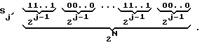
При размыкании j-го волоконно-оптического ключа ВОК 8-j из генеральной последовательности копий исчезнут первые 2j-1 копий. Последующие 2j-1 копий свободно пройдут на выход ДЗУ и т.д. Таким образом, если обозначить наличие копии на выходе устройства через "1", а отсутствие - через "0", то формируемую частную последовательность копий при размыкании только j-го волоконно-оптического ключа BOKj можно представить в виде двоичного слова Sj длиной в 2N разрядов:

Так, при размыкании только первого волоконно-оптического ключа ВОК 8-1 из генеральной последовательности копий останутся только копии с нечетными порядковыми номерами: 1, 3, 5,..., 2N-1, то есть с временем задержки копий τзад, 3τзад, 5τзад,...,(2N-1)τзад соответственно. Аналогично, при размыкании только второго ВОК 8-2 из всей последовательности копий останутся только копии с временами задержки 
Временные последовательности копий, получаемых при размыкании одного из ключей в случае ДЗУ с четырьмя ВОЛЗ, приведены на фиг.6б. Справа от каждой последовательности указан номер разомкнутого ключа. Первая последовательность соответствует случаю, когда все ключи замкнуты (генеральная последовательность).When the j-th fiber optic key VOK 8-j is opened, the first 2 j-1 copies will disappear from the general sequence of copies. The next 2 j-1 copies will go freely to the output of the DZU, etc. Thus, if we indicate the presence of a copy at the output of the device through "1", and the absence through "0", then the generated private sequence of copies when opening only the j-th fiber-optic key BOK j can be represented as a binary word S j with a length of 2 N bits:
So, when only the first fiber-optic key VOK 8-1 is opened from the general sequence of copies, only copies with odd serial numbers remain: 1, 3, 5, ..., 2 N -1, that is, with the copy delay time τ back , 3τ ass , 5τ ass , ..., (2 N -1) τ ass, respectively. Similarly, if only the second wok 8-2 is opened, only copies with delay times will remain from the entire sequence of copies.
Temporary sequences of copies obtained by opening one of the keys in the case of a DZU with four FOLs are shown in Fig.6b. To the right of each sequence is an open key number. The first sequence corresponds to the case when all keys are closed (general sequence).
Следует отметить, что при использовании для управления только первых N ВОК 8-1, ...,8-N в частных последовательностях формируемых копий всегда отсутствует нулевая и всегда присутствует последняя копии сигнала. It should be noted that when using only the first N FOCs 8-1, ..., 8-N for control, the zero sequences are always absent in the partial sequences of the generated copies and the last copy of the signal is always present.
Если представлять формируемые на выходе ДЗУ последовательности копий в виде двоичных слов, то такие слова для ДЗУ с четырьмя ВОЛЗ при размыкании соответствующего ВОК будут выглядеть следующим образом:
S1 0101010101010101
S2 0011001100110011
S3 0000111100001111
S4 0000000011111111
При одновременном размыкании двух и более ключей в бинарной ВОС вид формируемой частной последовательности легко можно получить путем поразрядного умножения двоичных слов, соответствующих размыканию каждого рассматриваемого ключа в отдельности. Так, при размыкании, например, первого ВОК 8-1 и второго ВОК 8-2 в ДЗУ с четырьмя ВОЛЗ двоичное слово S12 формируемой частной последовательности копий будет иметь вид
S1 0101010101010101
S2 0011001100110011
--------------------------
S12=S1•S2 0001000100010001
Варианты частных последовательностей копий при размыкании двух и трех ВОК для ДЗУ с четырьмя ВОЛЗ показаны на фиг.6в и фиг.6г соответственно.If we represent the sequences of copies formed at the output of the DZU in the form of binary words, then such words for the DZU with four FOLs when opening the corresponding FOC will look like this:
S 1 010101010101010101
S 2 0011001100110011
S 3 0000111100001111
S 4 0000000011111111
With the simultaneous opening of two or more keys in a binary OSI, the form of the formed private sequence can easily be obtained by bitwise multiplication of binary words corresponding to the opening of each key under consideration separately. So, when, for example, the first VOK 8-1 and the second VOK 8-2 are opened in the DZU with four VOLZs, the binary word S 12 of the formed private sequence of copies will have the form
S 1 010101010101010101
S 2 0011001100110011
--------------------------
S 12 = S 1 • S 2 0001000100010001
Variants of partial sequences of copies when opening two and three woks for a DZU with four FOLs are shown in Fig.6c and Fig.6d, respectively.
Следует отметить, что при использовании для управления только первых N ВОК 8-1, . . .,8-N размыкание каждого дополнительного ключа приводит к сокращению числа формируемых копий вдвое. В случае размыкания всех первых N ВОК 8-1,...,8-N в бинарной ВОС возможно формирование только одной копии входного сигнала - копии, которая проходит через все ВОЛЗ и имеет время задержки (2N-1)τзад (см. фиг.6д).It should be noted that when using for control only the first N woks 8-1,. . ., 8-N opening each additional key reduces the number of generated copies by half. In the case of the opening of all first N FOCs 8-1, ..., 8-N in a binary FOC, it is possible to form only one copy of the input signal - a copy that passes through all of the FOCL and has a delay time (2 N -1) τ back (cm Fig.6d).
Как видно из фиг. 6б-6д, управление копиями в ДЗУ с N ВОЛЗ и бинарной ВОС, при использовании для управления только первых N ВОК 8-1,...,8-N, позволяет:
1) увеличивать период следования копий в 2, 4, 8,...,2N-1 раза;
2) формировать пакеты копий в количестве 2, 4, 8,...,2N-1 импульсов;
3) изменять паузы между формируемыми копиями и пакетами копий (паузы эквивалентны временам формирования 2, 4, 8,...,2N-1 импульсов);
4) формировать только одну копию с временем задержки (2N-1)•τзад.
Число копий Xk, получаемых при одновременном размыкании k ключей (при использовании N ВОЛЗ), определяется выражением
Xk=2N-k.As can be seen from FIG. 6b-6d, managing copies in a DZU with N VOLZ and binary VOS, when using only the first N VOKs 8-1, ..., 8-N to control, allows:
1) increase the repetition period of copies by 2, 4, 8, ..., 2 N-1 times;
2) form packets of copies in the amount of 2, 4, 8, ..., 2 N-1 pulses;
3) change the pauses between generated copies and packages of copies (pauses are equivalent to the formation times of 2, 4, 8, ..., 2 N-1 pulses);
4) generate only one copy with a delay time (2 N -1) • τ ass .
The number of copies X k obtained by simultaneously opening k keys (when using N FOL) is determined by the expression
X k = 2 Nk .
Количество вариантов сочетаний Xk,N одновременно разомкнутых ключей числом k при их общем числе N можно определить по формуле
![]()
Общее количество возможных сочетаний разомкнутых ключей при использовании для управления только первых N ВОК 8-1,...,8-N и, следовательно, вариантов последовательностей копий будет равно
![]()
В случае управления процессом формирования копий при использовании для управления только последних N ВОК 8-(N+1),...,8-2N выражение (3), соответствующее двоичному слову Sj' для разомкнутого (N+j)-го волоконно-оптического ключа ВОКN+j, примет вид
При таком варианте управления в формируемых частных последовательностях копий будут всегда присутствовать нулевая и всегда отсутствовать последняя копии сигнала.The number of variants of combinations X k, N of simultaneously open keys with the number k with their total number N can be determined by the formula
![]()
The total number of possible combinations of open keys when used to control only the first N VOKs 8-1, ..., 8-N and, therefore, variants of sequences of copies will be equal
![]()
In the case of controlling the copying process when only the last N NOCs are used to control 8- (N + 1), ..., 8-2N expression (3) corresponding to the binary word S j ' for an open (N + j) -th fiber -OK optical key wok N + j , will take the form
With this control option, the null and always the last signal copies will always be present in the generated private sequences of copies.
Если представлять формируемые на выходе ДЗУ последовательности копий в виде двоичных слов, то такие слова для ДЗУ с четырьмя ВОЛЗ при размыкании соответствующего ВОК будут выглядеть следующим образом:
S1' 1010101010101010
S2' 1100110011001100
S3' 1111000011110000
S4' 1111111100000000
В остальном все рассуждения и способы получения частных последовательностей копий при размыкании нескольких ключей аналогичны приведенным выше.If we represent the sequences of copies formed at the output of the DZU in the form of binary words, then such words for the DZU with four FOLs when opening the corresponding FOC will look like this:
S 1 ' 1010101010101010
S 2 ' 1100110011001100
S 3 ' 1111000011110000
S 4 ' 1111111100000000
Otherwise, all arguments and methods for obtaining private sequences of copies when opening several keys are similar to those given above.
Значительно более широкие возможности по управлению последовательностью формируемых копий будут получены, если использовать для этих целей все BOK 8-1,...,8-2N. Significantly broader possibilities for managing the sequence of generated copies will be obtained if all BOK 8-1, ..., 8-2N are used for these purposes.
В этом случае заявляемое техническое решение имеет следующие преимущества:
1) за счет изменения сочетаний разомкнутых ВОК появляется возможность изменения относительного местоположения во времени (изменения номеров) формируемых копий сигнала при сохранении одного вида последовательности;
2) при одновременном размыкании j-го ВОК 8-j и (N+j)-го BOK 8-(N+j) формирование копий невозможно (происходит "выключение" ДЗУ без изменения режимов работы всех его основных модулей).In this case, the claimed technical solution has the following advantages:
1) by changing combinations of open woks, it becomes possible to change the relative location in time (change numbers) of the generated copies of the signal while maintaining one type of sequence;
2) with the simultaneous opening of the j-th wok 8-j and (N + j) -th BOK 8- (N + j), the formation of copies is impossible (there is a "shutdown" of the DZU without changing the operating modes of all its main modules).
Все рассуждения, касающиеся получения вида частных последовательностей копий, формируемых при одновременном размыкании произвольных ключей, остаются в силе: необходимо произвести поразрядное умножение двоичных слов, соответствующих размыканию каждого рассматриваемого ключа в отдельности. Так, при размыкании одновременно первого ВОК 8-1, (N+2)-го BOK 8-(N+2), (N+3)-го ВОК 8-(N+3) и четвертого ВОК 8-4 двоичное слово S12'3'4 формируемой частной последовательности для ДЗУ с четырьмя ВОЛЗ (N=4) будет иметь вид
S1 0101010101010101
S2' 1100110011001100
S3' 1111000011110000
S4 0000000011111111
S12'3'4=S1•S2'•S3'•S40000000001000000
Различные сочетания разомкнутых ключей позволяют изменять относительные местоположения формируемых копий при одном и том же виде их последовательности. На фиг.7а показаны различные варианты, получаемые при размыкании первого, второго, (N+1)-го и (N+2)-го ВОК (для N=4). а на фиг.7б - при размыкании второго, четвертого, (N+2)-го и (N+4)-го ВОК (для N=4) для ДЗУ с четырьмя ВОЛЗ.All considerations regarding obtaining the form of private sequences of copies formed by simultaneously opening arbitrary keys remain valid: bitwise multiplication of binary words corresponding to the opening of each key under consideration must be performed separately. So, when simultaneously opening the first wok 8-1, (N + 2) -th wok 8- (N + 2), (N + 3) th wok 8- (N + 3) and the fourth wok 8-4 binary word S 12'3'4 of the formed partial sequence for the DZU with four FOLs (N = 4) will have the form
S 1 010101010101010101
S 2 ' 1100110011001100
S 3 ' 1111000011110000
S 4 0000000011111111
S 12'3'4 = S 1 • S 2 ' • S 3' • S 4 0000000001000000
Various combinations of open keys allow you to change the relative locations of the generated copies with the same type of sequence. On figa shows the various options obtained by opening the first, second, (N + 1) -th and (N + 2) -th wok (for N = 4). and on figb - when opening the second, fourth, (N + 2) -th and (N + 4) -th wok (for N = 4) for the DZU with four FOL.
Интерес представляет изменение местоположения в случае формирования только одной копии - различные сочетания разомкнутых ключей позволяют получить копию с любым порядковым номером (см. фиг.7в). Of interest is a change in location in the case of the formation of only one copy — various combinations of open keys allow you to get a copy with any serial number (see figv).
Количество различных вариантов относительных местоположений формируемых последовательностей копий при k разомкнутых ключах с заданными номерами равно Yk=2k.The number of different variants of the relative locations of the generated sequences of copies with k open keys with given numbers is Y k = 2 k .
Общее число возможных вариантов получения различных последовательностей копий (с учетом различных местоположений) для ДЗУ с N ВОЛЗ определяется выражением
![]()
На фиг.8 показаны результаты проведенных по формулам (6) и (9) расчетов вариантов получаемых копий.The total number of possible options for obtaining different sequences of copies (taking into account different locations) for DZU with N FOL is determined by the expression
![]()
On Fig shows the results of calculations carried out according to formulas (6) and (9) of the variants of the obtained copies.
Например, для ДЗУ с управляемой бинарной ВОС при использовании трех ВОЛЗ (N= 3) возможно формирование 27 различных последовательностей копий. Все данные варианты последовательностей представлены на фиг.9. For example, for DZU with controlled binary VOS using three FOLs (N = 3), it is possible to form 27 different sequences of copies. All of these sequence options are presented in Fig.9.
Таким образом, заявляемое техническое решение позволяет формировать временную последовательность из 2N копий входного радиосигнала с периодом следования τзад, а также за счет возможности управления процессом тиражирования:
1) увеличивать период следования копий в 2, 4, 8,...,2 N-1 раза;
2) формировать пакеты копий в количестве 2, 4, 8,...,2N-1 импульсов;
3) изменять паузы между формируемыми копиями и пакетами копий (паузы эквивалентны временам формирования 2, 4, 8,...,2N-1 импульсов);
4) изменять относительное местоположение во времени (изменять номера) формируемых копий сигнала при сохранении одного и того же вида последовательности;
5) формировать одну копию с любым номером (временем задержки 0,...,τзад,2τзад,...,(2N-1)•τзад).Thus, the claimed technical solution allows you to generate a time sequence of 2 N copies of the input radio signal with a repetition period τ ass , and also due to the ability to control the replication process:
1) increase the repetition period of copies by 2, 4, 8, ..., 2 N-1 times;
2) form packets of copies in the amount of 2, 4, 8, ..., 2 N-1 pulses;
3) change the pauses between generated copies and packages of copies (pauses are equivalent to the formation times of 2, 4, 8, ..., 2 N-1 pulses);
4) change the relative location in time (change numbers) of the generated copies of the signal while maintaining the same type of sequence;
5) generate one copy with any number (delay
Данные преимущества заявляемого объекта позволяют значительно расширить возможности управления процессом формирования последовательности копий по сравнению с прототипом (патент 5177488 США, МКИ G 01 S 007/40). Это доказывает наличие причинно-следственной связи между заявляемой совокупностью признаков и техническим результатом в части значительного расширения возможности управления процессом формирования последовательности копий. These advantages of the claimed object can significantly expand the ability to control the process of forming a sequence of copies in comparison with the prototype (US patent 5177488, MKI G 01 S 007/40). This proves the existence of a causal relationship between the claimed combination of features and the technical result in terms of significantly expanding the ability to control the process of forming a sequence of copies.
Для доказательства сохранения высокой идентичности копий составим сигнальную модель ДЗУ с бинарной ВОС. To prove the preservation of high identity of the copies, we will compose a signal model of the DZU with binary VOS.
Направленные волноводные ответвители, используемые в заявляемом объекте, конструктивно представляют собой два световода, имеющих участок соприкосновения сердцевин, за счет чего осуществляется ответвление части оптической энергии из одного ВС в другой. The directional waveguide couplers used in the claimed object are structurally two fibers having a contact area of the cores, due to which a part of the optical energy is branched from one aircraft to another.
Если на входной порт разделительного НВО Y-типа НВО 7 подать оптический сигнал jнво.7.вх, то на его втором и третьем выходных портах будут действовать оптические сигналы с интенсивностями


Здесь коэффициенты ответвления Кнво.7.n определяют, какая часть интенсивности излучения поступает со входного порта в n-й порт в случае идеального НВО. Коэффициенты ответвления удовлетворяют условию Кнво.7.1= 1-Кнво.7.2.If an optical signal j NVO.7.input is applied to the input port of a Y-type HBO separation NVO, then optical signals with intensities will act on its second and third output ports
Here, the branch coefficients K nv. 7..n determine how much of the radiation intensity comes from the input port to the n-th port in the case of an ideal NWO. The branch coefficients satisfy the condition K nvo . 7.1 = 1-K nvo . 7.2 .
В реальных ответвителях всегда присутствуют потери световой энергии, которые выражаются в том, что суммарная интенсивность излучения на выходных портах НВО не совпадает с интенсивностью входного излучения. Указанные потери учитываются в формулах (6) параметром γНВО.7.
При подаче на первый и второй входные порты k-го НВО Х-типа НВО 10-k оптических сигналов с интенсивностями Jнво. 10-k.1 и Jнво. 10-k.2 на его третьем и четвертом выходных портах появляются оптические излучения с интенсивностями


Здесь коэффициенты ответвления Кнво .10-k.mn определяют, какая часть интенсивности излучения поступает с m-порта в n-й порт в случае идеального НВО. Коэффициенты ответвления НВО Х-типа всегда удовлетворяют условию Kнвo. 10-k.13=1-Кнво. 10-k.14 и Кнво. 10-k.23=1-Кнво. 10-k.24.In real couplers, there are always losses of light energy, which are expressed in the fact that the total radiation intensity at the output ports of the HBO does not coincide with the intensity of the input radiation. These losses are taken into account in formulas (6) by the parameter Н HBO . 7 .
When applying to the first and second input ports of the k-th HBO HB-type HBO 10-k optical signals with intensities J HBO. 10-k.1 and J nvo. 10-k.2 optical radiation with intensities appears at its third and fourth output ports
Here, the branch coefficients K nvo .10-k.mn determine how much of the radiation intensity comes from the m-port to the nth port in the case of an ideal IEE. The branch coefficients of an X-type IEE are always satisfying the condition of K IEE. 10-k.13 = 1-K NVO. 10-k.14 and K nvo. 10-k.23 = 1-K NVO. 10-k.24 .
Суммирующий НВО Y-типа 11 описывается следующим уравнением:

Волоконно-оптические линии задержки, используемые в заявляемом объекте, представляют собой отрезки ВС, обеспечивающие задержку проходящего сигнала на заданное время. Учитывая, что типовое значение погонной задержки ВС составляет примерно 5 мкс/км, длина отрезка ВС для j-й ВОЛЗ 9-j в первом приближении составляет
Lволз.9-j[км] ≈ 0,1•2jτзад[мкс]. (9)
Следует отметить, что преимуществом ДЗУ с бинарной ВОС над ДЗУ рециркуляционного типа является то, что все копии радиосигнала проходят через одинаковое количество портов НВО и соединений ВС, обеспечивая тем самым равные потери оптического излучения для всех копий. Неидентичность сформированных копий определяется лишь потерями, обусловленными различной длиной световодов, используемых в ВОЛЗ. Так, нулевая копия i=0 сигнала формируется без прохождения оптического излучения через какую-либо ВОЛЗ. Это обеспечивает минимальные потери сигнала. Последняя копия (i=M), напротив, должна пройти через все ВОЛЗ. Потери сигнала здесь будут наибольшими.The summarizing HBO of the Y-
Fiber optic delay lines used in the claimed object are segments of the aircraft, providing a delay of the transmitted signal for a given time. Given that the typical value of the linear delay of the aircraft is approximately 5 μs / km, the length of the segment of aircraft for the j-th FOCL 9-j in a first approximation is
L wave 9-j [km] ≈ 0.1 • 2 j τ back [μs]. (9)
It should be noted that the advantage of a binary VOS DZU over a recirculation type DZU is that all copies of the radio signal pass through the same number of HBO ports and aircraft connections, thereby ensuring equal optical radiation loss for all copies. The identity of the generated copies is determined only by losses due to the different lengths of the optical fibers used in the fiber optic cable. So, a zero copy of the i = 0 signal is formed without optical radiation passing through any fiber optic link. This ensures minimal signal loss. The last copy (i = M), on the contrary, should go through all the VOLZ. Signal loss here will be greatest.
Общие потери радиосигнала в ДЗУ при формировании i-й копии
αi[дБ] = αpc[дБ]+αпреоб[дБ]+2αвос.i[дБ] (10)
определяются потерями мощности радиосигнала αpc в радиотракте, потерями в цикле преобразования радиосигнал - оптическое излучение - радиосигнал αпреоб и потерями интенсивности оптического излучения в ВОС αвос.i. Множитель 2 при αвос.i в формуле (10) учитывает тот факт, что электрическая мощность радиосигнала на выходе фотодетектора пропорциональна квадрату интенсивности оптического излучения.The total loss of radio signal in the ROM during the formation of the i-th copy
α i [dB] = α pc [dB] + α prev [dB] + 2α asc .i [dB] (10)
are determined by the power loss of the radio signal α pc in the radio path, the losses in the conversion cycle of the radio signal - optical radiation - the radio signal α pre and losses of the intensity of optical radiation in VOS α vosi . The
Анализ структурной схемы ДЗУ с управляемой бинарной ВОС (фиг.1) показывает, что источниками потерь мощности СВЧ-сигнала в радиотракте являются СВЧ-разъемы αразъемы и рассогласование импедансов αсогл.вх функциональных узлов во входном радиотракте.An analysis of the structural diagram of a DZU with a controlled binary VOS (Fig. 1) shows that the sources of microwave power loss in the radio path are the microwave connectors α connectors and the impedance mismatch α according to the functional units in the input radio path.
В устройстве используется шесть СВЧ-разъемов: входные и выходные разъемы широкополосного усилителя ШУ 1 и делителя мощности ДМ 2, входной разъем ПОМ и выходной разъем фотодетектора. Типовое значение потерь радиосигнала на разъеме составляет 0,1 дБ. Таким образом, суммарные потери, вносимые СВЧ-разъемами, оцениваются в αразъемы ≈ 0,6 дБ.
Последовательное соединение функциональных узлов проектируемого ДЗУ по СВЧ-сигналу для минимизации энергетических потерь требует выполнения условия согласования, при котором мощность источника сигнала полностью поглощается нагрузкой. Согласование обеспечивается равенством входных и выходных импедансов используемых СВЧ-модулей.The device uses six microwave connectors: input and output connectors of a
The serial connection of the functional units of the designed DZU by the microwave signal to minimize energy losses requires the fulfillment of the matching condition, in which the power of the signal source is completely absorbed by the load. Matching is ensured by the equality of the input and output impedances of the used microwave modules.
Потери мощности в случае рассогласования импедансов во входном радиотракте определяются соотношением
αсогл.вх[дБ] = -10lg[(1-Г1Г2)•(1-Г3Г4)],
где Г1, Г2, Г3, Г4 - коэффициенты отражения соответственно входного широкополосного усилителя ШУ 1 по выходу, делителя мощности ДМ 2 по входу, делителя мощности ДМ 2 по выходу, ПОМ по входу.Power losses in case of mismatch of impedances in the input radio path are determined by the relation
α acc. [dB] = -10lg [(1-G 1 G 2 ) • (1-G 3 G 4 )],
where G 1 , G 2 , G 3 , G 4 - reflection coefficients, respectively, of the input
Коэффициенты отражения Г однозначно определяются приводимыми в технических характеристиках функциональных узлов значениями коэффициентов стоячей волны напряжения КСВН:
![]()
Коэффициентам КСВН широкополосного усилителя, делителя мощности и ПОМ, равным 2, соответствует коэффициент отражения Г=(2-1)/(2+l)=l/3. При этом потери мощности радиосигнала за счет рассогласования во входном радиотракте составят
![]()
Таким образом, общие потери мощности радиосигнала составляют
αpc = αсогл.вх+αразъемы ≈ 1,0+0,6 = 1,6 дБ.
Использование в ДЗУ волоконно-оптических линий задержки требует преобразования входного СВЧ-сигнала в оптическое излучение посредством модуляции излучения передающего оптического модуля по интенсивности радиосигналом.The reflection coefficients Г are unambiguously determined by the values of the coefficients of the standing voltage wave of the VSWR given in the technical specifications of the functional units:
![]()
The VSWR coefficients of the broadband amplifier, power divider, and POM equal to 2 correspond to the reflection coefficient Г = (2-1) / (2 + l) = l / 3. In this case, the power loss of the radio signal due to the mismatch in the input radio path will be
![]()
Thus, the total power loss of the radio signal is
α pc = α as per I + α connectors ≈ 1.0 + 0.6 = 1.6 dB.
The use of fiber-optic delay lines in the DZU requires the conversion of the input microwave signal into optical radiation by modulating the radiation of the transmitting optical module by the intensity of the radio signal.
Параметром, характеризующим преобразование радиосигнала в излучение оптического диапазона, является крутизна преобразования (дифференциальная квантовая эффективность источника излучения) Sипл, определяемая в соответствии с ватт-амперной характеристикой излучателя и измеряемая в Вт/А.The parameter characterizing the conversion of the radio signal into optical range radiation is the steepness of the conversion (differential quantum efficiency of the radiation source) S IPL , determined in accordance with the watt-ampere characteristic of the emitter and measured in W / A.
Коэффициент преобразования интенсивности оптического излучения, падающей на фоточувствительную площадку фотодетектора Jфд, в фототoк Iфд (электрический сигнал) характеризуется токовой чувствительностью εфд фотодетектора, которая измеряется в А/Вт и обычно указывается в паспортных данных.The conversion factor of the intensity of optical radiation incident on the photosensitive area of the photodetector PD J in fototok I PD (electric signal) is characterized by a current sensitivity ε photodetector PD, which is measured in A / W, and is usually specified in passport information.
Потери на преобразование радиосигнала в оптическое излучение в передающем оптическом модуле со входным сопротивлением Rвх.пом и на преобразование оптического излучения в радиосигнал в фотоприемном модуле с сопротивлением нагрузки фотодетектора Rн.фд могут быть рассчитаны по формуле
![]()
При Sипл= 75 мВт/А, εфд=0,35 А/Вт и Rн.пом=Rн.фд=50 Ом потери на преобразование радиосигнала в оптическое излучение составляют
![]()
Основными источниками потерь интенсивности оптического излучения являются:
- ввод оптического излучения лазера в волоконный световод;
- потери в замкнутых ВОК;
- потери сигнала, вносимые НВО;
- потери сигнала, возникающие за счет оптических соединений;
- распространение оптического излучения в волоконно-оптических линиях задержки;
- вывод оптического излучения из волоконного световода.Losses on the conversion of the radio signal into optical radiation in the transmitting optical module with an input impedance R I.pom and on the conversion of optical radiation into a radio signal in the photodetector module with load resistance of the photodetector R n.fd can be calculated by the formula
![]()
When S IPL = 75 mW / A, ε fd = 0.35 A / W and R n.pom = R n.fd = 50 Ohm, the losses due to the conversion of the radio signal into optical radiation are
![]()
The main sources of optical radiation intensity loss are:
- input of optical laser radiation into a fiber waveguide;
- losses in closed woks;
- signal loss introduced by IEE;
- signal loss due to optical connections;
- propagation of optical radiation in fiber-optic delay lines;
- output of optical radiation from a fiber waveguide.
Обусловленные вводом в волоконный световод потери интенсивности оптического излучения составят

Отметим, что для модулей ПОМ-13, ПОМ-13М и ПОМ-19 в справочных данных дается введенная в волоконный световод интенсивность оптического излучения. В этом случае интенсивность ![]()
Note that for the POM-13, POM-13M, and POM-19 modules, the reference data gives the optical radiation intensity introduced into the optical fiber. In this case, the intensity ![]()
В качестве первого и (N+1)-го BOK в заявляемом устройстве необходимо использовать быстродействующие ключи, например, электрооптического типа. Остальные BOK могут быть и других типов. Механические BOK характеризуются низким уровнем оптических потерь αмех.вок = 0,8...1 дБ, потребляемой мощностью в несколько милливатт и недостаточно высоким быстродействием (5...50 мс). Электрооптические переключатели на одномодовых световодах имеют оптические потери, включая потери на соединение с волоконными световодами, порядка αэо.вок = 2...2,5 дБ, скорость переключения до 6 ГТц и управляющие напряжения 4...10 В.As the first and (N + 1) -th BOK in the inventive device, it is necessary to use high-speed keys, for example, electro-optical type. Other BOKs may be of other types. Mechanical BOKs are characterized by a low level of optical losses α mech.wave = 0.8 ... 1 dB, power consumption of several milliwatts and insufficiently high speed (5 ... 50 ms). Electro-optical switches on single-mode optical fibers have optical losses, including losses due to connection with fiber optical fibers, of the order of α eo.voc = 2 ... 2.5 dB, switching speed up to 6 GHz and control voltages of 4 ... 10 V.
Таким образом, суммарные потери в BOK αвок при формировании любой копии сигнала будут равны
αвок[дБ] = αэо.вок[дБ]+(N-1)•αмех.вок[дБ].
Собственные потери оптического излучения в световодах обусловлены технологией производства волоконных световодов и указываются в технических характеристиках. Минимальными собственными потерями интенсивности оптического излучения обладают одномодовые волоконные световоды типа кварц-кварц, рабочая длина волны которых составляет λ=1,55 мкм. Типичное значение погонного ослабления (потерь) оптического излучения для данного типа ВС отечественного производства составляет Гвс=0,2 дБ/км.Thus, the total loss in BOK α wok during the formation of any copy of the signal will be equal
α wok [dB] = α eo.wok [dB] + (N-1) • α mechanical wok [dB].
The intrinsic losses of optical radiation in the optical fibers are caused by the technology for the production of optical fibers and are indicated in the technical specifications. Single-mode quartz-quartz fiber waveguides with a working wavelength of λ = 1.55 μm possess the minimum intrinsic loss of optical radiation intensity. A typical value of the specific attenuation (loss) of optical radiation for this type of aircraft of domestic production is G sun = 0.2 dB / km.
Отрезок ВС для j-й ВОЛЗ 9-j длиной Lволз.9-j будет обладать потерями
αволз.9-j[дБ] = Гвс[дБ/км]•Lволз.9-j[км].
С учетом формулы (9) суммарные потери на распространение оптического излучения в волоконных световодах при формировании i-й копии радиосигнала определяются выражением
![]()
Заметим, что потери в бинарной ВОС зависят от текущего номера i формируемой копии радиосигнала при заданном количестве ВОЛЗ N.The segment of the aircraft for the j-th fiber optic cable 9-j of length L wave-9-j will have losses
α wave 9-j [dB] = G sun [dB / km] • L wave 9-j [km].
Taking into account formula (9), the total losses due to the propagation of optical radiation in optical fibers during the formation of the ith copy of the radio signal are determined by the expression
![]()
Note that the losses in the binary BOC depend on the current number i of the generated copy of the radio signal for a given number of fiber optic lines N.
Потери оптического излучения в НВО возникают из-за деления сигнала в разделительном НВО Y-типа 7, из-за деления сигнала в НВО Х-типа 10-1,..., 10-(N-1), а также потерь оптического сигнала на рассеивание при прохождении всех (N+1) НВО. В случае, когда коэффициенты деления во всех ответвителях X-типа и в разделительном ответвителе Y-типа одинаковы и равны Кнво=0,5(≈-3 дБ), а также потери γнво во всех ответвителях одинаковы, суммарные потери оптического излучения в НВО составят
γНВО[дБ] = -N•KНВО[дБ]+(N+1)•γНВО[дБ]. (12)
Потери сигнала, возникающие за счет оптических соединений в ВОС, могут быть найдены по формуле
αсоед[дБ] = 4αконн[дБ]+2(N+1)αНВО-ВС[дБ], (13)
где αконн - потери в одном разъемном оптическом коннекторе;
αНВО-ВС - потери на соединение порта НВО с волоконным световодом ВОЛЗ или ВОК.Loss of optical radiation in a HBO occurs due to signal division in the separation UB of the Y-
γ IEE [dB] = -N • K IEE [dB] + (N + 1) • γ IEE [dB]. (12)
The signal loss due to optical connections in VOS can be found by the formula
α connection [dB] = 4α connection [dB] +2 (N + 1) α HBO-BC [dB], (13)
where α conn is the loss in one detachable optical connector;
α HBO-BC - losses on the connection of the HBO port to the fiber optic fiber optic cable FOCL or FOC
Следует отметить, что оптические соединения выхода ПОМ 3 с входом ВОУ 4, выхода ВОУ 4 с входным портом разделительного НВО Y-типа 7, выходного порта суммирующего НВО Y-типа 11 с входом фотодетектора ФД 5 выполняются разъемными с помощью оптических коннекторов с потерями на одном коннекторе αконн, не превышающими 0,2...0,3 дБ.It should be noted that the optical connections of the
Соединение волоконного световода ВОЛЗ или ВОК с портами НВО выполняются неразъемными (методами сплавлеиия или склеивания). The fiber optic fiber optic fiber optic coupler or fiber optic cable is connected to HBO ports in one piece (fusion or bonding methods).
Конструктивные требования к волоконно-оптическим линиям задержки радиосигналов предполагают наматывание волоконного световода на катушку диаметром Dкат. Кольцевой изгиб волоконного световода вызывают дополнительные потери интенсивности оптического излучения в ВС.The design requirements for fiber-optic delay lines for radio signals suggest winding a fiber into a coil with a diameter of D cat . The annular bending of a fiber waveguide causes additional losses in the intensity of optical radiation in the sun.
Если потери на один виток составляют αвиток, то потери интенсивности оптического излучения в катушке j-й ВОЛЗ 9-j составят
![]()
Суммарные потери в кольцевых изгибах волоконных световодов при формировании i-й копии радиосигнала определяются выражением

Использование волоконного световода с относительно малым диаметром сердцевины по отношению к фоточувствительной площадке фотоприемника позволяет не учитывать потери интенсивности оптического излучения на вывод оптического излучения из бинарной волоконно-оптической структуры в фотодетектор.If the loss per turn is α turn , then the loss of the intensity of optical radiation in the coil of the j-th FOCL 9-j will be
![]()
The total losses in the annular bends of the optical fibers during the formation of the i-th copy of the radio signal are determined by the expression
The use of a fiber waveguide with a relatively small core diameter with respect to the photosensitive area of the photodetector allows you to ignore the loss of optical radiation intensity to the output of optical radiation from the binary fiber-optic structure to the photodetector.
Общие потери интенсивности оптического излучения при формировании i-й копии радиосигнала составляют

На фиг. 10 приведены данные о потерях оптического излучения αвос.M для последней копии радиосигнала в зависимости от количества N используемых ВОЛЗ. Расчеты проведены по формулам (11)-(15) при следующих исходных данных: τзад = 100 нс, КНВО = -3 дБ, γнво = 0,1 дБ, ГВС = 0,22 дБ/км, αэо.вок = 2 дБ, αмех.вок = 0,8 дБ, αввод = 4,3 дБ, DКАТ = 250 мм, αвиток = 0,0001 дБ, αконн = 0,2 дБ, αнво-вс = 0,15 дБ.
Из фиг.10 видно, что при N<13 основной вклад в ослабление сигнала вносят потери в НВО αнво, а при N>13 основными факторами ослабления сигнала становятся его затухание в ВС ВОЛЗ αвс.M и потери в кольцевых изгибах волокна αизг.M
Проведенный анализ показывает, что определяющими потерями в ДЗУ являются потери в цикле преобразования радиосигнал - оптическое излучение - радиосигнал αпреоб и потери интенсивности оптического излучения в ВОС αвос.i при формировании i-й копии радиосигнала.The total loss of optical radiation intensity during the formation of the i-th copy of the radio signal is
In FIG. 10 shows the data on optical radiation loss α vos.M for the last copy of the radio signal, depending on the number N of FOLs used. The calculations were performed according to formulas (11) - (15) with the following initial data: τ ass = 100 ns, K IEE = -3 dB, γ IEE = 0.1 dB, G BC = 0.22 dB / km, α eo. wok = 2 dB, α mechanical wok = 0.8 dB, α input = 4.3 dB, D CAT = 250 mm, α turn = 0.0001 dB, α conn = 0.2 dB, α NVO-Sun = 0.15 dB
From Figure 10 it is seen that when N <13, the main contribution to attenuation losses introduced in IEE IEE α, and if N> 13, the main signal attenuation factors become its attenuation α vs.M Volz sun and ring losses in the bends of the fiber α mfd .M
The analysis shows that the determining losses in the DZU are the losses in the conversion cycle of the radio signal - optical radiation - the radio signal α pre and loss of the intensity of optical radiation in the VOS α vosi during the formation of the i-th copy of the radio signal.
Пусть на вход ДЗУ (см. фиг.1) в момент времени t0 воздействует одиночный широкополосный СВЧ-радиосигнал (2) длительностью τи. Напряжение на входе ПОМ uвх.пом(t) связано с напряжением входного сигнала uc(t) устройства соотношением
uвх.пом(t)=Кшу.вхКдм.1uc(t)=Uвх.помm(t)cosФ(t),
где Кшу.вх - коэффициент усиления напряжения входного широкополосного усилителя ШУ 1 с учетом потерь радиосигнала на СВЧ-разъемах;
Кдм.1 - коэффициент передачи делителя мощности с входа на первый выход (см. фиг.1) с учетом потерь радиосигнала на СВЧ-разъемах.Let the input of the DZU (see Fig. 1) at time t 0 be affected by a single broadband microwave radio signal (2) of duration τ and . The voltage at the input of the POM u input p (t) is related to the voltage of the input signal u c (t) of the device by the ratio
u input.pom (t) = K input.c input dm . 1 u c (t) = U input.pom m (t) cos Φ (t),
where K shu.vh - voltage gain of the input
To dm.1 - the transfer coefficient of the power divider from the input to the first output (see figure 1), taking into account the loss of radio signal on the microwave connectors.
Применение полупроводникового лазера (ИПЛ), излучающего на рабочей длине волны λ, допускает непосредственную модуляцию интенсивности оптического излучения Jпом (t) простым изменением тока накачки:
iн(t)=uвх.пом(t)/Rвх.пом=Iнm(t)cosФ(t).The use of a semiconductor laser (IPL) emitting at a working wavelength λ allows direct modulation of the optical radiation intensity J pom (t) by a simple change in the pump current:
i n (t) = u i.pom (t) / R i.pom = I n m (t) cos Φ (t).
Здесь Rвх.пом представляет реальную часть входного сопротивления ПОМ, а Iн= Uвх.пом/Rвх.пом - амплитуду тока накачки лазера в отсутствии амплитудной модуляции радиосигнала.Here, R input pom represents the real part of the input impedance of the POM, and I n = U input p / R input pom is the amplitude of the laser pump current in the absence of amplitude modulation of the radio signal.
Характерной особенностью зависимости излучения инжекционного полупроводникового лазера Jипл(t) от тока накачки iн(t) является наличие порогового значения Iн.пор. При выборе постоянного тока смещения ПОМ Iн.см, удовлетворяющего условию
Iн.см-Iн.пор>Iн.макс,
справедливо соотношение
Jипл(t)=Jипл.0+Jипл.с(t). (16)
Первое слагаемое в формуле (16) Jипл.0=SиплIн.см представляет постоянную составляющую интенсивности оптического излучения лазера в отсутствии радиосигнала.A characteristic feature of the dependence of the radiation of the injection semiconductor laser J IPL (t) on the pump current i n (t) is the presence of the threshold value I n p . When choosing a DC bias current POM I n.cm , satisfying the condition
I n.cm -I n.pore > I n.max ,
fair ratio
J melt (t) = J melee 0 + J melee with (t). (16)
The first term in formula (16) J mp 0 = S mp I n.cm represents the constant component of the intensity of the laser optical radiation in the absence of a radio signal.
Информация о входном сигнале заключена во втором слагаемом формулы (16) Jипл.с(t)=SиплIиm(t)cosФ(t).Information about the input signal is contained in the second term of the formula (16) J s.s. (t) = S s.s. I and m (t) cos Φ (t).
Глубина модуляции интенсивности может быть рассчитана по формуле
![]()
Обусловленные вводом в ВС потери интенсивности оптического излучения равны αввод. При этом Jпом(t)[дБ] = Jипл(t)[дБ]-αввод[дБ].
Следует отметить, что в общем случае в качестве фотодетектора ФД 5 может выступать фотоприемный модуль (ФПМ), состоящий из непосредственно фотодетектора какого-либо типа (pin-фотодиод, лавинный фотодиод, фототранзистор и т.п.) и встроенного широкополосного усилителя с коэффициентом усиления напряжения Кшу.фпм.The depth of intensity modulation can be calculated by the formula
![]()
The losses in the intensity of optical radiation due to the introduction into the sun are equal to α input . In this case, J pom (t) [dB] = J IPL (t) [dB] -α input [dB].
It should be noted that in the general case, the photodetector module (FPM), consisting of a photodetector of some type (pin photo diode, avalanche photo diode, photo transistor, etc.) and an integrated broadband amplifier with a gain voltage K shu.fpm .
В соответствии с формулой (14) интенсивность сигнальной составляющей светового потока на фотодетекторе при формировании i-й копии радиосигнала равна

где Квоу - коэффициент передачи интенсивности оптического излучения волоконно-оптическим усилителем ВОУ 4.In accordance with formula (14), the intensity of the signal component of the light flux at the photodetector during the formation of the ith copy of the radio signal is
where K HEU is the transmission coefficient of the intensity of the optical radiation of the fiber-
Радиосигнал на выходе устройства (выходе фотоприемного модуля) определяется выражением
uвых(t-iτзад) = εфдJфд.c(t-iτзад)Rн.фдKшу.фпм, (17)
где Кшу.фпм - коэффициент усиления напряжения внутренним усилителем ФПМ.The radio signal at the output of the device (the output of the photodetector module) is determined by the expression
u O (t-iτ backside) = ε FD J fd.c (t-iτ backside) R n.fd shu.fpm K, (17)
where K shu.ffm - voltage gain by the internal amplifier FPM.
Из соотношения (17) следует, что переменная составляющая напряжения на выходе ДЗУ в момент времени t∈[t0+iτзад, t0+τи+iτзад] повторяет по форме входной широкополосный радиосигнал (2) с задержкой по времени на величину iτзад.
Мощность радиосигнала (2) на входном сопротивлении Rвх.дзу ДЗУ (входном сопротивлении входного широкополосного усилителя ШУ 1 на фиг.1) равна
Рс=Uc 2/2Rвx.дзy.From relation (17) it follows that the variable component of the voltage at the output of the DZU at time t∈ [t 0 + iτ ass , t 0 + τ and + iτ ass ] repeats the shape of the input broadband radio signal (2) with a time delay of iτ ass
The power of the radio signal (2) at the input impedance R i.dzu DZU (input impedance of the input
P c = U c 2 / 2R in x.dzy .
При расчете энергетических параметров ДЗУ из-за большого динамического диапазона изменений уровня входного радиосигнала удобно пользоваться логарифмическими единицами, переход к которым позволяет свести основные расчеты мощностей радиосигналов к операциям сложения и вычитания. В качестве нулевого уровня интенсивности (мощности) принято значение I0=1 мВт (Р0=1 мВт), которое примерно соответствует максимальной интенсивности оптического излучения полупроводникового лазера. Тогда текущей интенсивности I или мощности Р будет соответствовать уровень

Если на вход устройства в момент времени t∈[t0, t0+τи] воздействует радиосигнал (2) мощностью Рс, то в момент времени t∈[t0+iτзад, t0+τи+iτзад] на выходе устройства будет присутствовать i-я копия (1) радиосигнала мощностью

где Кр.шу.вх, Кр.дм.1, Кр.шу.фпм - коэффициенты усиления мощности входного широкополосного усилителя ШУ 1, делителя мощности ДМ 2, усилительного каскада ФПМ соответственно.When calculating the energy parameters of the DZU due to the large dynamic range of changes in the level of the input radio signal, it is convenient to use logarithmic units, the transition to which allows us to reduce the basic calculations of the power of the radio signals to the operations of addition and subtraction. The value of I 0 = 1 mW (P 0 = 1 mW), which approximately corresponds to the maximum intensity of the optical radiation of a semiconductor laser, is taken as the zero intensity (power) level. Then the current intensity I or power P will correspond to the level
If at the moment of time t∈ [t 0 , t 0 + τ and ] the radio signal (2) with a power of P s acts, then at time t ∈ [t 0 + iτ back , t 0 + τ and + iτ back ] the i-th copy (1) of the radio signal with power
where K r.shu.vh , K r.dmu.1 , K r.shu.fpm - power gain of the input
Выражение (18) удобно представить в виде
Pi[дБ] = Pc[дБм]+K0[дБ]-Δαi[дБ],
где К0 - коэффициент, равный отношению мощности Р0 нулевой копии радиосигнала (принимаемой без задержки) к мощности Pc входного радиосигнала (2):

Ослабление мощности i-й копии относительно мощности нулевой копии радиосигнала оценивается выражением
Δαi[дБ] = P0[дБм]-Pi[дБм].
С учетом соотношений (10), (11), (14) и (15) находим
![]()
Вводимый параметр (19) может быть использован для характеристики неидентичности по мощности копий радиосигнала в пределах формируемой последовательности ![]()
ΔαM[дБ] = 2M•(αвс.1[дБ]+αизг.1[дБ]) = M•Δα1. (20)
Здесь множитель 2 имеет тот же смысл, что и в формуле (10) при слагаемом αвос.i.
Как следует из формулы (20), неидентичность М сформированных копий радиосигнала ΔαM в ДЗУ с бинарной ВОС может быть рассчитана через потери за счет затухания оптического излучения в световоде ВОЛЗ αвс.1 и конструктивные потери на изгиб αизг.1 во время генерации 1-й копии радиосигнала.Expression (18) is conveniently represented as
P i [dB] = P c [dBm] + K 0 [dB] -Δα i [dB],
where K 0 is a coefficient equal to the ratio of the power P 0 of the zero copy of the radio signal (received without delay) to the power P c of the input radio signal (2):
The attenuation of the power of the i-th copy relative to the power of the zero copy of the radio signal is estimated by the expression
Δα i [dB] = P 0 [dBm] -P i [dBm].
Given relations (10), (11), (14) and (15), we find
![]()
The input parameter (19) can be used to characterize the non-identity of the power of the copies of the radio signal within the generated sequence ![]()
Δα M [dB] = 2M • (α whole 1 [dB] + α outgoing 1 [dB]) = M • Δα 1 . (20)
Here, the
As follows from formula (20), the non-identity of M formed copies of the radio signal Δα M in the DZU with binary BOC can be calculated through the losses due to the attenuation of the optical radiation in the fiber optic fiber optics fiber optic cable α v. 1 and the design bending loss α of curve 1 during
Графически зависимость (19) показана на фиг.11. Исходными данными для расчетов служили погонное затухание оптического излучения в ВС Гвс=0,2 дБ/км, потери на один виток αвиток = 10-4 дБ и диаметр Dкат=250 мм кольцевого изгиба волоконного световода в катушке. Значения временной задержки τзад изменялись в пределе от 50 до 200 нс с шагом в 50 нс.Graphically, the dependence (19) is shown in Fig. 11. The initial data for the calculations were the specific attenuation of the optical radiation in the aircraft, G vs = 0.2 dB / km, loss per turn α turn = 10 -4 dB and diameter D cat = 250 mm of the annular bending of the optical fiber in the coil. The values of the time delay τ ass varied in the range from 50 to 200 ns in increments of 50 ns.
В случае формирования 15-й копий с периодом задержки 100 нс (использование четырех ВОЛЗ) неидентичность копий составит
Δα15 = 2•15•(0,004+0,0025)≈0,2 дБ.
Из фиг.11 можно заключить, что амплитуда сформированных копий монотонно убывает с увеличением номера копии. Мощность каждой последующей сформированной копии радиосигнала на выходе ДЗУ будет отличаться от предшествующей при τзад=100 нс на 0,013 дБ, а при τзад=200 нс на 0,026 дБ.In the case of the formation of the 15th copies with a delay period of 100 ns (the use of four FOCLs), the identity of the copies will be
Δα 15 = 2 • 15 • (0.004 + 0.0025) ≈0.2 dB.
From Fig. 11 it can be concluded that the amplitude of the generated copies decreases monotonically with increasing copy number. The power of each subsequent generated copy of the radio signal at the output of the DZU will differ from the previous one at τ ass = 100 ns by 0.013 dB, and at τ ass = 200 ns by 0.026 dB.
Проведенный анализ позволяет заключить, что главным преимуществом ДЗУ на бинарной ВОС является высокая идентичность копий. В случае формирования 15-ти копий (время задержки одной копии τзад=100 нс) разница в мощностях нулевой и последней копий радиосигнала составляет около 0,2 дБ.The analysis allows us to conclude that the main advantage of DZU on binary OSI is the high identity of the copies. In the case of the formation of 15 copies (the delay time of one copy τ ass = 100 ns), the difference in the power of the zero and last copies of the radio signal is about 0.2 dB.
Следует отметить, что прототип заявляемого объекта (патент 5177488 США, МКИ G 01 S 007/40) характеризуется такими же факторами, влияющими на идентичность формируемых копий. It should be noted that the prototype of the claimed object (US patent 5177488, MKI G 01 S 007/40) is characterized by the same factors affecting the identity of the generated copies.
Описанная сигнальная модель ДЗУ доказывает наличие причинно-следственной связи между заявляемой совокупностью признаков и достигаемым техническим результатом в части сохранения высокой идентичности формируемых копий. The described signal model of the DZU proves the existence of a causal relationship between the claimed combination of features and the achieved technical result in terms of maintaining a high identity of the generated copies.
Доказательство сохранения малого расхода волоконного световода в заявляемом объекте приводится ниже. Proof of the conservation of low consumption of the fiber in the claimed object is given below.
Рециркуляционные устройства волоконно-оптической памяти, описанные в патентах 4473270 США, МКИ G 02 B 005/172 (см. фиг.12) и 4479701 США, МКИ G 02 B 005/172 (см. фиг.13), обладают наименьшим расходом волоконного световода, определяемым периодом следования копий. Однако данные устройства характеризуются высоким затуханием сигнала от копии к копии в связи с последовательным выводом части энергии оптического излучения из процесса циркуляции. В результате при постоянном уровне шумов фотоприемника отношение сигнал/шум копий на выходе таких устройств быстро снижается, что в конечном итоге и обуславливает малое время хранения информации и высокую неидентичность копий. The fiber-optic memory recirculation devices described in US Pat. Nos. 4,473,270, MKI G 02 B 005/172 (see Fig. 12) and US 4479701, MKI G 02 B 005/172 (see Fig. 13) have the lowest fiber consumption fiber, determined by the repetition period of the copies. However, these devices are characterized by high attenuation of the signal from copy to copy in connection with the serial output of a part of the optical radiation energy from the circulation process. As a result, at a constant noise level of the photodetector, the signal-to-noise ratio of copies at the output of such devices quickly decreases, which ultimately leads to a short storage time of information and a high non-identity of the copies.
Общая длина используемого световода в динамических устройствах памяти на основе многоотводных ВОЛЗ, описанных в патентах 4558920 США, МКИ G 02 B 005/172 (см. фиг.14) и 4557552 США, МКИ G 02 B 005/172 (см. фиг.15), как и в заявляемом объекте пропорциональна количеству формируемых копий. The total length of the used fiber in dynamic memory devices based on multi-tap fiber optic links described in US patents 4558920, MKI G 02 B 005/172 (see Fig. 14) and 4557552 US, MKI G 02 B 005/172 (see Fig. 15 ), as in the claimed object, is proportional to the number of generated copies.
Для формирования М копий входного сигнала с периодом следования τзад устройство, описанном в патенте 4128759 США, МКИ Н 04 В 009/00 (см. фиг.15), необходимо использование М световодов общей длиной порядка 0,5•М2•L, что в М/2 раз превышает длину используемого ВС в заявляемом объекте (где L - длина ВС, обеспечивающего задержку τзад).For the formation of M copies of the input signal with the period following the back of the device described in US patent 4128759, MKI N 04 V 009/00 (see Fig. 15), it is necessary to use M optical fibers with a total length of the order of 0.5 • M 2 • L, which is M / 2 times the length of the aircraft used in the inventive facility (where L is the length of the aircraft, providing a delay τ ass ).
В устройстве волоконно-оптической динамической памяти, описанном в патенте 4976518 США, МКИ G 02 B 006/26 (см. фиг.17), формирование М копий входного сигнала потребует применения ВС общей длиной порядка М•L•log3М, что в log3M раз превышает длину используемого ВС в заявляемом объекте (где L - длина ВС, обеспечивающего задержку τзад).In the fiber optic dynamic memory device described in US Pat. No. 4,976,518, MKI G 02 B 006/26 (see FIG. 17), the formation of M copies of the input signal will require the use of aircraft with a total length of the order of M • L • log 3 M, which log 3 M times the length of the aircraft used in the inventive facility (where L is the length of the aircraft providing a delay τ ass ).
Программируемая ВОЛЗ (патент 5177488 США, МКИ G 01 S 007/40), предназначенная для использования в системах тестирования радиолокационных станций (см. фиг. 18), характеризуется такими же факторами, влияющими на расход ВС, что и заявляемый объект. Programmable fiber optic link (US patent 5177488, MKI G 01 S 007/40), intended for use in testing systems of radar stations (see Fig. 18), is characterized by the same factors affecting aircraft consumption as the claimed object.
Проведенный анализ доказывает наличие причинно-следственной связи между заявляемой совокупностью признаков и достигаемым техническим результатом в части сохранения малого расхода волоконного световода. The analysis proves the existence of a causal relationship between the claimed combination of features and the achieved technical result in terms of maintaining a low fiber consumption.
Функциональные элементы динамического запоминающего устройства с управляемой бинарной волоконно-оптической структурой и устройство в целом (см. фиг.1) удовлетворяют критерию промышленного применения. The functional elements of a dynamic storage device with a controlled binary fiber optic structure and the device as a whole (see Fig. 1) satisfy the criterion of industrial use.
Применительно к элементам схемы ДЗУ 1-5, 7-11 (см. фиг.1) можно отметить следующее. Промышленность освоила и серийно выпускает довольно широкий класс полупроводниковых лазерных излучателей и передающих оптических модулей на длину волны 1,3-1,55 мкм, способных работать в одномодовом режиме при комнатной температуре и обладающих приемлемыми потребительскими характеристиками. В частности, передающий оптический модуль ПОМ-13М имеет следующие основные данные (Стручева О.Ф., Безбородова Т.М. Изделия волоконно-оптической техники: Каталог. - М.: Экос, 1993. - 142 с.): длина волны излучения 1,3... 1,55 мкм, мощность излучения 1 мВт, ширина огибающей спектра 0,01 им, скорость передачи информации 5 Гбит/с, одночастотный режим генерации. With regard to the elements of the circuit DZU 1-5, 7-11 (see figure 1), the following can be noted. The industry has mastered and mass-produced a fairly wide class of semiconductor laser emitters and transmitting optical modules at a wavelength of 1.3-1.55 microns, capable of operating in a single mode at room temperature and having acceptable consumer characteristics. In particular, the transmitting optical module POM-13M has the following basic data (Strucheva O.F., Bezborodova T.M. Products of fiber-optic technology: Catalog. - M .: Ekos, 1993. - 142 p.): Radiation wavelength 1.3 ... 1.55 microns, a radiation power of 1 mW, a spectral envelope width of 0.01 im, an information transfer rate of 5 Gbit / s, a single-frequency generation mode.
Полоса пропускания современных одномодовых волоконных световодов достигает 100 ГТц•км н более при групповой задержке сигнала порядка 5 мкс/км и дисперсии на длине волны 1,3 мкм не более 3,5 пс/(нм км) (Братчиков А.Н. Волоконно-оптические линии задержки широкополосных радиосигналов. // Зарубежная радиоэлектроника. - 1988. - N 3. - С.85-94). The bandwidth of modern single-mode fiber optic fibers reaches 100 GHz • km and more with a group signal delay of about 5 μs / km and a dispersion of 1.3 μm at a maximum of 3.5 ps / (nm km) (Bratchikov A.N. optical delay lines of broadband radio signals. // Foreign Radio Electronics. - 1988. -
Среди отечественных волоконно-оптических усилителей можно отметить ОА-850 и ОА-1300 с коэффициентами усиления КВОУ, равными 6 и 10 дБ при уровне входного сигнала 20...100 мкВт (изготовитель НИИ "Волга" НПО "Рефлектор") и одномодовый волоконно-оптический усилитель на длину волны 1,53...1,55 мкм (кооператив "Файбероптик"). Фирма "Пирелли КАВИ СПА" (Италия) предлагает оптический усилитель "AMPLIPHOS" на эрбиевом волокне, работающий в оптическом диапазоне λ=1530...1560 нм и обеспечивающий оптимальное усиление Квоу= 22...30 дБ, а коэффициент шума Швоу не превышает 4 дБ.Among domestic fiber-optic amplifiers, OA-850 and OA-1300 can be noted with 6 KUU gain equal to 10 and 10 dB at an input signal level of 20 ... 100 μW (manufacturer of the Research Institute "Volga" NPO "Reflector") and single-mode fiber -optical amplifier for a wavelength of 1.53 ... 1.55 microns (cooperative "Fiberoptik"). The company Pirelli CAVI SPA (Italy) offers an optical amplifier "AMPLIPHOS" on erbium fiber, operating in the optical range λ = 1530 ... 1560 nm and providing optimal gain K wow = 22 ... 30 dB, and noise figure W wow does not exceed 4 dB.
В настоящее время существуют различные типы волоконно-оптических ключей. Механические ВОК характеризуются низким уровнем оптических потерь (0,5...1 дБ), потребляемой мощностью в несколько милливатт и недостаточно высоким быстродействием (10. . .50 мс), что и является их основным недостатком. Волоконно-оптические переключатели на жидких кристаллах не имеют движущихся частей и потенциально более надежны механических. Оптические потери у данного типа ВОК составляют 1...2 дБ, потребляемая мощность 30...50 мкВт и скорость переключения 5. ..50 мс. Акусто- и магнитооптические ВОК на объемных элементах обеспечивают скорость переключения около 10-6 с-1 и имеют уровень оптических потерь 2...3 дБ. Электрооптические переключатели на одномодовых полосковых световодах имеют оптические потери, включая потери на соединение с волоконными световодами, порядка 2...3 дБ, скорость переключения до 6 ГГц и управляющие напряжения 4...10 В.Currently, there are various types of fiber optic keys. Mechanical FOCs are characterized by a low level of optical losses (0.5 ... 1 dB), power consumption of several milliwatts and insufficiently high speed (10. ... 50 ms), which is their main drawback. Liquid crystal fiber optic switches do not have moving parts and are potentially more reliable mechanical ones. Optical losses for this type of FOC are 1 ... 2 dB, power consumption 30 ... 50 μW and switching
Фотоприемные устройства обычно представляют собой сочетание фотодиода и каскада предварительного усиления сигнала фотоответа. Максимальная полоса детектируемых сигналов серийных фотодиодов достигает 5...10 ГГц при чувствительности по интенсивности оптического излучения порядка -30 дБм, динамическом диапазоне 20...25 дБ и крутизне характеристик детектирования 0,5... 0,8 А/Вт по току (Стручева О.Ф., Безбородова Т.М. Изделия волоконно-оптической техники: Каталог. - М.: Экос, 1993. - 142 с.)
По данным работы Микроэлектронные устройства СВЧ. / Под ред. Г.И. Веселова. - М. : Высшая школа, 1988. - С.68-75, многоступенчатые делители мощности обеспечивают развязку выходных плеч без применения вентильных устройств до 30 дБ в полосе частот с коэффициентом перекрытия диапазона 1,44. С использованием современных ферритовых вентилей (Ферритовые СВЧ приборы. // Производственное объединение "Гранит", г. Ростов на Дону, 1992) развязка плеч делителя может быть увеличена не менее чем на 25...30 дБ при прямых потерях порядка 0,5...0,8 дБ.Photodetectors are usually a combination of a photodiode and a pre-amplification stage of the photoresponse signal. The maximum detectable signal band of serial photodiodes reaches 5 ... 10 GHz with a sensitivity of optical radiation of the order of -30 dBm, a dynamic range of 20 ... 25 dB and a steepness of the detection characteristics of 0.5 ... 0.8 A / W current (Strucheva O.F., Bezborodova T.M. Products of fiber-optic technology: Catalog. - M .: Ekos, 1993. - 142 p.)
According to the work of microelectronic microwave devices. / Ed. G.I. Veselova. - M.: Vysshaya Shkola, 1988. - P.68-75, multi-stage power dividers provide decoupling of output arms without the use of gate devices up to 30 dB in the frequency band with a band overlap coefficient of 1.44. Using modern ferrite gates (Ferrite microwave devices. // Production Association "Granite", Rostov-on-Don, 1992) the decoupling of the divider arms can be increased by at least 25 ... 30 dB with direct losses of the order of 0.5. ..0.8 dB.
В качестве широкополосных усилителей в настоящее время наиболее широко используются транзисторные усилители, работающие в диапазоне частот 0,1...25 ГГц и имеющие полосу усиления 4...80%, коэффициент усиления на каскад 5...30 дБ, коэффициент шума 2...6 дБ и динамический диапазон входного сигнала 80... 90 дБ (Микроэлектронные устройства СВЧ. / Под ред. Г.И. Веселова. - М.: Высшая школа, 1988. - с.78-86, 225). Currently, transistor amplifiers operating in the frequency range of 0.1 ... 25 GHz and having a gain band of 4 ... 80%, a gain per stage of 5 ... 30 dB, and a noise figure of 2 are most widely used as broadband amplifiers. ... 6 dB and the dynamic range of the
Все элементы БУ 6 также удовлетворяют критерию промышленного применения. Формирователи импульсов легко реализуются на основе, например, последовательного соединения дифференцирующей цепи, усилителя-ограничителя и (при необходимости) инвертора. All elements of
Claims (1)
Priority Applications (1)
| Application Number | Priority Date | Filing Date | Title |
|---|---|---|---|
| RU2002116859/09A RU2213421C1 (en) | 2002-06-21 | 2002-06-21 | Dynamic radio-signal memory device |
Applications Claiming Priority (1)
| Application Number | Priority Date | Filing Date | Title |
|---|---|---|---|
| RU2002116859/09A RU2213421C1 (en) | 2002-06-21 | 2002-06-21 | Dynamic radio-signal memory device |
Publications (2)
| Publication Number | Publication Date |
|---|---|
| RU2213421C1 true RU2213421C1 (en) | 2003-09-27 |
| RU2002116859A RU2002116859A (en) | 2004-02-10 |
Family
ID=29777789
Family Applications (1)
| Application Number | Title | Priority Date | Filing Date |
|---|---|---|---|
| RU2002116859/09A RU2213421C1 (en) | 2002-06-21 | 2002-06-21 | Dynamic radio-signal memory device |
Country Status (1)
| Country | Link |
|---|---|
| RU (1) | RU2213421C1 (en) |
Cited By (41)
| Publication number | Priority date | Publication date | Assignee | Title |
|---|---|---|---|---|
| WO2013066631A1 (en) * | 2011-10-18 | 2013-05-10 | The General Hospital Corporation | Apparatus and methods for producing and/or providing recirculating optical delay(s) |
| US8676013B2 (en) | 2004-07-02 | 2014-03-18 | The General Hospital Corporation | Imaging system using and related techniques |
| US8760663B2 (en) | 2005-09-29 | 2014-06-24 | The General Hospital Corporation | Method and apparatus for optical imaging via spectral encoding |
| US8922781B2 (en) | 2004-11-29 | 2014-12-30 | The General Hospital Corporation | Arrangements, devices, endoscopes, catheters and methods for performing optical imaging by simultaneously illuminating and detecting multiple points on a sample |
| US9060689B2 (en) | 2005-06-01 | 2015-06-23 | The General Hospital Corporation | Apparatus, method and system for performing phase-resolved optical frequency domain imaging |
| US9069130B2 (en) | 2010-05-03 | 2015-06-30 | The General Hospital Corporation | Apparatus, method and system for generating optical radiation from biological gain media |
| US9178330B2 (en) | 2009-02-04 | 2015-11-03 | The General Hospital Corporation | Apparatus and method for utilization of a high-speed optical wavelength tuning source |
| US9186066B2 (en) | 2006-02-01 | 2015-11-17 | The General Hospital Corporation | Apparatus for applying a plurality of electro-magnetic radiations to a sample |
| US9282931B2 (en) | 2000-10-30 | 2016-03-15 | The General Hospital Corporation | Methods for tissue analysis |
| US9330092B2 (en) | 2011-07-19 | 2016-05-03 | The General Hospital Corporation | Systems, methods, apparatus and computer-accessible-medium for providing polarization-mode dispersion compensation in optical coherence tomography |
| US9326682B2 (en) | 2005-04-28 | 2016-05-03 | The General Hospital Corporation | Systems, processes and software arrangements for evaluating information associated with an anatomical structure by an optical coherence ranging technique |
| US9408539B2 (en) | 2010-03-05 | 2016-08-09 | The General Hospital Corporation | Systems, methods and computer-accessible medium which provide microscopic images of at least one anatomical structure at a particular resolution |
| US9415550B2 (en) | 2012-08-22 | 2016-08-16 | The General Hospital Corporation | System, method, and computer-accessible medium for fabrication miniature endoscope using soft lithography |
| US9441948B2 (en) | 2005-08-09 | 2016-09-13 | The General Hospital Corporation | Apparatus, methods and storage medium for performing polarization-based quadrature demodulation in optical coherence tomography |
| US9510758B2 (en) | 2010-10-27 | 2016-12-06 | The General Hospital Corporation | Apparatus, systems and methods for measuring blood pressure within at least one vessel |
| US9516997B2 (en) | 2006-01-19 | 2016-12-13 | The General Hospital Corporation | Spectrally-encoded endoscopy techniques, apparatus and methods |
| US9557154B2 (en) | 2010-05-25 | 2017-01-31 | The General Hospital Corporation | Systems, devices, methods, apparatus and computer-accessible media for providing optical imaging of structures and compositions |
| US9615748B2 (en) | 2009-01-20 | 2017-04-11 | The General Hospital Corporation | Endoscopic biopsy apparatus, system and method |
| US9629528B2 (en) | 2012-03-30 | 2017-04-25 | The General Hospital Corporation | Imaging system, method and distal attachment for multidirectional field of view endoscopy |
| USRE46412E1 (en) | 2006-02-24 | 2017-05-23 | The General Hospital Corporation | Methods and systems for performing angle-resolved Fourier-domain optical coherence tomography |
| US9733460B2 (en) | 2014-01-08 | 2017-08-15 | The General Hospital Corporation | Method and apparatus for microscopic imaging |
| US9763623B2 (en) | 2004-08-24 | 2017-09-19 | The General Hospital Corporation | Method and apparatus for imaging of vessel segments |
| US9784681B2 (en) | 2013-05-13 | 2017-10-10 | The General Hospital Corporation | System and method for efficient detection of the phase and amplitude of a periodic modulation associated with self-interfering fluorescence |
| US9795301B2 (en) | 2010-05-25 | 2017-10-24 | The General Hospital Corporation | Apparatus, systems, methods and computer-accessible medium for spectral analysis of optical coherence tomography images |
| US9968261B2 (en) | 2013-01-28 | 2018-05-15 | The General Hospital Corporation | Apparatus and method for providing diffuse spectroscopy co-registered with optical frequency domain imaging |
| US9968245B2 (en) | 2006-10-19 | 2018-05-15 | The General Hospital Corporation | Apparatus and method for obtaining and providing imaging information associated with at least one portion of a sample, and effecting such portion(s) |
| US10058250B2 (en) | 2013-07-26 | 2018-08-28 | The General Hospital Corporation | System, apparatus and method for utilizing optical dispersion for fourier-domain optical coherence tomography |
| US10117576B2 (en) | 2013-07-19 | 2018-11-06 | The General Hospital Corporation | System, method and computer accessible medium for determining eye motion by imaging retina and providing feedback for acquisition of signals from the retina |
| US10228556B2 (en) | 2014-04-04 | 2019-03-12 | The General Hospital Corporation | Apparatus and method for controlling propagation and/or transmission of electromagnetic radiation in flexible waveguide(s) |
| US10285568B2 (en) | 2010-06-03 | 2019-05-14 | The General Hospital Corporation | Apparatus and method for devices for imaging structures in or at one or more luminal organs |
| US10413175B2 (en) | 2006-05-10 | 2019-09-17 | The General Hospital Corporation | Process, arrangements and systems for providing frequency domain imaging of a sample |
| US10426548B2 (en) | 2006-02-01 | 2019-10-01 | The General Hosppital Corporation | Methods and systems for providing electromagnetic radiation to at least one portion of a sample using conformal laser therapy procedures |
| US10478072B2 (en) | 2013-03-15 | 2019-11-19 | The General Hospital Corporation | Methods and system for characterizing an object |
| US10736494B2 (en) | 2014-01-31 | 2020-08-11 | The General Hospital Corporation | System and method for facilitating manual and/or automatic volumetric imaging with real-time tension or force feedback using a tethered imaging device |
| US10835110B2 (en) | 2008-07-14 | 2020-11-17 | The General Hospital Corporation | Apparatus and method for facilitating at least partial overlap of dispersed ration on at least one sample |
| US10893806B2 (en) | 2013-01-29 | 2021-01-19 | The General Hospital Corporation | Apparatus, systems and methods for providing information regarding the aortic valve |
| US10912462B2 (en) | 2014-07-25 | 2021-02-09 | The General Hospital Corporation | Apparatus, devices and methods for in vivo imaging and diagnosis |
| US11179028B2 (en) | 2013-02-01 | 2021-11-23 | The General Hospital Corporation | Objective lens arrangement for confocal endomicroscopy |
| US11452433B2 (en) | 2013-07-19 | 2022-09-27 | The General Hospital Corporation | Imaging apparatus and method which utilizes multidirectional field of view endoscopy |
| US11490826B2 (en) | 2009-07-14 | 2022-11-08 | The General Hospital Corporation | Apparatus, systems and methods for measuring flow and pressure within a vessel |
| US11490797B2 (en) | 2012-05-21 | 2022-11-08 | The General Hospital Corporation | Apparatus, device and method for capsule microscopy |
-
2002
- 2002-06-21 RU RU2002116859/09A patent/RU2213421C1/en not_active IP Right Cessation
Cited By (50)
| Publication number | Priority date | Publication date | Assignee | Title |
|---|---|---|---|---|
| US9282931B2 (en) | 2000-10-30 | 2016-03-15 | The General Hospital Corporation | Methods for tissue analysis |
| US8676013B2 (en) | 2004-07-02 | 2014-03-18 | The General Hospital Corporation | Imaging system using and related techniques |
| US9664615B2 (en) | 2004-07-02 | 2017-05-30 | The General Hospital Corporation | Imaging system and related techniques |
| US9763623B2 (en) | 2004-08-24 | 2017-09-19 | The General Hospital Corporation | Method and apparatus for imaging of vessel segments |
| US8922781B2 (en) | 2004-11-29 | 2014-12-30 | The General Hospital Corporation | Arrangements, devices, endoscopes, catheters and methods for performing optical imaging by simultaneously illuminating and detecting multiple points on a sample |
| US9326682B2 (en) | 2005-04-28 | 2016-05-03 | The General Hospital Corporation | Systems, processes and software arrangements for evaluating information associated with an anatomical structure by an optical coherence ranging technique |
| US9060689B2 (en) | 2005-06-01 | 2015-06-23 | The General Hospital Corporation | Apparatus, method and system for performing phase-resolved optical frequency domain imaging |
| US9441948B2 (en) | 2005-08-09 | 2016-09-13 | The General Hospital Corporation | Apparatus, methods and storage medium for performing polarization-based quadrature demodulation in optical coherence tomography |
| US8760663B2 (en) | 2005-09-29 | 2014-06-24 | The General Hospital Corporation | Method and apparatus for optical imaging via spectral encoding |
| US8928889B2 (en) | 2005-09-29 | 2015-01-06 | The General Hospital Corporation | Arrangements and methods for providing multimodality microscopic imaging of one or more biological structures |
| US9513276B2 (en) | 2005-09-29 | 2016-12-06 | The General Hospital Corporation | Method and apparatus for optical imaging via spectral encoding |
| US9516997B2 (en) | 2006-01-19 | 2016-12-13 | The General Hospital Corporation | Spectrally-encoded endoscopy techniques, apparatus and methods |
| US9186067B2 (en) | 2006-02-01 | 2015-11-17 | The General Hospital Corporation | Apparatus for applying a plurality of electro-magnetic radiations to a sample |
| US9186066B2 (en) | 2006-02-01 | 2015-11-17 | The General Hospital Corporation | Apparatus for applying a plurality of electro-magnetic radiations to a sample |
| US10426548B2 (en) | 2006-02-01 | 2019-10-01 | The General Hosppital Corporation | Methods and systems for providing electromagnetic radiation to at least one portion of a sample using conformal laser therapy procedures |
| USRE46412E1 (en) | 2006-02-24 | 2017-05-23 | The General Hospital Corporation | Methods and systems for performing angle-resolved Fourier-domain optical coherence tomography |
| US10413175B2 (en) | 2006-05-10 | 2019-09-17 | The General Hospital Corporation | Process, arrangements and systems for providing frequency domain imaging of a sample |
| US9968245B2 (en) | 2006-10-19 | 2018-05-15 | The General Hospital Corporation | Apparatus and method for obtaining and providing imaging information associated with at least one portion of a sample, and effecting such portion(s) |
| US10835110B2 (en) | 2008-07-14 | 2020-11-17 | The General Hospital Corporation | Apparatus and method for facilitating at least partial overlap of dispersed ration on at least one sample |
| US9615748B2 (en) | 2009-01-20 | 2017-04-11 | The General Hospital Corporation | Endoscopic biopsy apparatus, system and method |
| US9178330B2 (en) | 2009-02-04 | 2015-11-03 | The General Hospital Corporation | Apparatus and method for utilization of a high-speed optical wavelength tuning source |
| US11490826B2 (en) | 2009-07-14 | 2022-11-08 | The General Hospital Corporation | Apparatus, systems and methods for measuring flow and pressure within a vessel |
| US10463254B2 (en) | 2010-03-05 | 2019-11-05 | The General Hospital Corporation | Light tunnel and lens which provide extended focal depth of at least one anatomical structure at a particular resolution |
| US9642531B2 (en) | 2010-03-05 | 2017-05-09 | The General Hospital Corporation | Systems, methods and computer-accessible medium which provide microscopic images of at least one anatomical structure at a particular resolution |
| US9408539B2 (en) | 2010-03-05 | 2016-08-09 | The General Hospital Corporation | Systems, methods and computer-accessible medium which provide microscopic images of at least one anatomical structure at a particular resolution |
| US9951269B2 (en) | 2010-05-03 | 2018-04-24 | The General Hospital Corporation | Apparatus, method and system for generating optical radiation from biological gain media |
| US9069130B2 (en) | 2010-05-03 | 2015-06-30 | The General Hospital Corporation | Apparatus, method and system for generating optical radiation from biological gain media |
| US9557154B2 (en) | 2010-05-25 | 2017-01-31 | The General Hospital Corporation | Systems, devices, methods, apparatus and computer-accessible media for providing optical imaging of structures and compositions |
| US10939825B2 (en) | 2010-05-25 | 2021-03-09 | The General Hospital Corporation | Systems, devices, methods, apparatus and computer-accessible media for providing optical imaging of structures and compositions |
| US9795301B2 (en) | 2010-05-25 | 2017-10-24 | The General Hospital Corporation | Apparatus, systems, methods and computer-accessible medium for spectral analysis of optical coherence tomography images |
| US10285568B2 (en) | 2010-06-03 | 2019-05-14 | The General Hospital Corporation | Apparatus and method for devices for imaging structures in or at one or more luminal organs |
| US9510758B2 (en) | 2010-10-27 | 2016-12-06 | The General Hospital Corporation | Apparatus, systems and methods for measuring blood pressure within at least one vessel |
| US9330092B2 (en) | 2011-07-19 | 2016-05-03 | The General Hospital Corporation | Systems, methods, apparatus and computer-accessible-medium for providing polarization-mode dispersion compensation in optical coherence tomography |
| US9341783B2 (en) | 2011-10-18 | 2016-05-17 | The General Hospital Corporation | Apparatus and methods for producing and/or providing recirculating optical delay(s) |
| WO2013066631A1 (en) * | 2011-10-18 | 2013-05-10 | The General Hospital Corporation | Apparatus and methods for producing and/or providing recirculating optical delay(s) |
| US9629528B2 (en) | 2012-03-30 | 2017-04-25 | The General Hospital Corporation | Imaging system, method and distal attachment for multidirectional field of view endoscopy |
| US11490797B2 (en) | 2012-05-21 | 2022-11-08 | The General Hospital Corporation | Apparatus, device and method for capsule microscopy |
| US9415550B2 (en) | 2012-08-22 | 2016-08-16 | The General Hospital Corporation | System, method, and computer-accessible medium for fabrication miniature endoscope using soft lithography |
| US9968261B2 (en) | 2013-01-28 | 2018-05-15 | The General Hospital Corporation | Apparatus and method for providing diffuse spectroscopy co-registered with optical frequency domain imaging |
| US10893806B2 (en) | 2013-01-29 | 2021-01-19 | The General Hospital Corporation | Apparatus, systems and methods for providing information regarding the aortic valve |
| US11179028B2 (en) | 2013-02-01 | 2021-11-23 | The General Hospital Corporation | Objective lens arrangement for confocal endomicroscopy |
| US10478072B2 (en) | 2013-03-15 | 2019-11-19 | The General Hospital Corporation | Methods and system for characterizing an object |
| US9784681B2 (en) | 2013-05-13 | 2017-10-10 | The General Hospital Corporation | System and method for efficient detection of the phase and amplitude of a periodic modulation associated with self-interfering fluorescence |
| US10117576B2 (en) | 2013-07-19 | 2018-11-06 | The General Hospital Corporation | System, method and computer accessible medium for determining eye motion by imaging retina and providing feedback for acquisition of signals from the retina |
| US11452433B2 (en) | 2013-07-19 | 2022-09-27 | The General Hospital Corporation | Imaging apparatus and method which utilizes multidirectional field of view endoscopy |
| US10058250B2 (en) | 2013-07-26 | 2018-08-28 | The General Hospital Corporation | System, apparatus and method for utilizing optical dispersion for fourier-domain optical coherence tomography |
| US9733460B2 (en) | 2014-01-08 | 2017-08-15 | The General Hospital Corporation | Method and apparatus for microscopic imaging |
| US10736494B2 (en) | 2014-01-31 | 2020-08-11 | The General Hospital Corporation | System and method for facilitating manual and/or automatic volumetric imaging with real-time tension or force feedback using a tethered imaging device |
| US10228556B2 (en) | 2014-04-04 | 2019-03-12 | The General Hospital Corporation | Apparatus and method for controlling propagation and/or transmission of electromagnetic radiation in flexible waveguide(s) |
| US10912462B2 (en) | 2014-07-25 | 2021-02-09 | The General Hospital Corporation | Apparatus, devices and methods for in vivo imaging and diagnosis |
Also Published As
| Publication number | Publication date |
|---|---|
| RU2002116859A (en) | 2004-02-10 |
Similar Documents
| Publication | Publication Date | Title |
|---|---|---|
| RU2213421C1 (en) | Dynamic radio-signal memory device | |
| RU2255426C1 (en) | Radio-signal dynamic memory device having series binary fiber- optic system | |
| US4671605A (en) | Length dependent, optical time delay/filter device for electrical signals | |
| US5896476A (en) | Optical loop signal processing using reflection mechanisms | |
| US4910539A (en) | RF frequency fiber optic power coupling device | |
| CN105762646A (en) | Semiconductor chaotic laser integrated with double feedback | |
| CN107925477A (en) | Monitored using the optical-fiber network of photon switch | |
| US4405858A (en) | Light gate with controlled optical couplers | |
| CN108089267B (en) | A kind of optical-fiber type broadband light vortex converter | |
| KR20140068795A (en) | Broadband light source | |
| AU2012101920A4 (en) | System and method for synchronizing light pulses at a selected location | |
| JPS62502818A (en) | Coherent radiation generation method and device | |
| JP2744092B2 (en) | Laser equipment for optical communication equipment | |
| CN202903210U (en) | Fiber grating sensing device | |
| CN102111222B (en) | Full-light generator of ultra wide band (UWB) multi-cycle pulse signals | |
| CN218782406U (en) | Coherent wind measurement laser radar system | |
| Alekseev et al. | Increasing the peak power of a pulsed laser source using optical delay lines | |
| US5530778A (en) | Direction finding apparatus using tunable fiber optic delay line | |
| Murshid et al. | Architecture of an all optical de-multiplexer for spatially multiplexed channels | |
| CN108919428A (en) | A kind of optical fiber integration module and microstructure fiber device | |
| CN110989268B (en) | All-optical logic gate | |
| RU2722085C1 (en) | Photonic fiber-optic module | |
| CN208953731U (en) | A kind of optical fiber integration module and microstructure fiber device | |
| You et al. | All-optical photonic signal processors with negative coefficients | |
| CN112332199B (en) | All-fiber high-repetition-frequency pulse generation system and method |
Legal Events
| Date | Code | Title | Description |
|---|---|---|---|
| MM4A | The patent is invalid due to non-payment of fees |
Effective date: 20040622 |