JP7160935B2 - Imaging system - Google Patents
Imaging system Download PDFInfo
- Publication number
- JP7160935B2 JP7160935B2 JP2020546313A JP2020546313A JP7160935B2 JP 7160935 B2 JP7160935 B2 JP 7160935B2 JP 2020546313 A JP2020546313 A JP 2020546313A JP 2020546313 A JP2020546313 A JP 2020546313A JP 7160935 B2 JP7160935 B2 JP 7160935B2
- Authority
- JP
- Japan
- Prior art keywords
- assembly
- connector
- imaging probe
- imaging
- optical
- Prior art date
- Legal status (The legal status is an assumption and is not a legal conclusion. Google has not performed a legal analysis and makes no representation as to the accuracy of the status listed.)
- Active
Links
Images


Classifications
-
- A—HUMAN NECESSITIES
- A61—MEDICAL OR VETERINARY SCIENCE; HYGIENE
- A61B—DIAGNOSIS; SURGERY; IDENTIFICATION
- A61B1/00—Instruments for performing medical examinations of the interior of cavities or tubes of the body by visual or photographical inspection, e.g. endoscopes; Illuminating arrangements therefor
- A61B1/00131—Accessories for endoscopes
- A61B1/00133—Drive units for endoscopic tools inserted through or with the endoscope
-
- A—HUMAN NECESSITIES
- A61—MEDICAL OR VETERINARY SCIENCE; HYGIENE
- A61B—DIAGNOSIS; SURGERY; IDENTIFICATION
- A61B5/00—Measuring for diagnostic purposes; Identification of persons
- A61B5/68—Arrangements of detecting, measuring or recording means, e.g. sensors, in relation to patient
- A61B5/6846—Arrangements of detecting, measuring or recording means, e.g. sensors, in relation to patient specially adapted to be brought in contact with an internal body part, i.e. invasive
- A61B5/6847—Arrangements of detecting, measuring or recording means, e.g. sensors, in relation to patient specially adapted to be brought in contact with an internal body part, i.e. invasive mounted on an invasive device
- A61B5/6852—Catheters
-
- A—HUMAN NECESSITIES
- A61—MEDICAL OR VETERINARY SCIENCE; HYGIENE
- A61B—DIAGNOSIS; SURGERY; IDENTIFICATION
- A61B1/00—Instruments for performing medical examinations of the interior of cavities or tubes of the body by visual or photographical inspection, e.g. endoscopes; Illuminating arrangements therefor
- A61B1/00112—Connection or coupling means
- A61B1/00121—Connectors, fasteners and adapters, e.g. on the endoscope handle
- A61B1/00126—Connectors, fasteners and adapters, e.g. on the endoscope handle optical, e.g. for light supply cables
-
- A—HUMAN NECESSITIES
- A61—MEDICAL OR VETERINARY SCIENCE; HYGIENE
- A61B—DIAGNOSIS; SURGERY; IDENTIFICATION
- A61B1/00—Instruments for performing medical examinations of the interior of cavities or tubes of the body by visual or photographical inspection, e.g. endoscopes; Illuminating arrangements therefor
- A61B1/00112—Connection or coupling means
- A61B1/00121—Connectors, fasteners and adapters, e.g. on the endoscope handle
- A61B1/00128—Connectors, fasteners and adapters, e.g. on the endoscope handle mechanical, e.g. for tubes or pipes
-
- A—HUMAN NECESSITIES
- A61—MEDICAL OR VETERINARY SCIENCE; HYGIENE
- A61B—DIAGNOSIS; SURGERY; IDENTIFICATION
- A61B1/00—Instruments for performing medical examinations of the interior of cavities or tubes of the body by visual or photographical inspection, e.g. endoscopes; Illuminating arrangements therefor
- A61B1/06—Instruments for performing medical examinations of the interior of cavities or tubes of the body by visual or photographical inspection, e.g. endoscopes; Illuminating arrangements therefor with illuminating arrangements
- A61B1/07—Instruments for performing medical examinations of the interior of cavities or tubes of the body by visual or photographical inspection, e.g. endoscopes; Illuminating arrangements therefor with illuminating arrangements using light-conductive means, e.g. optical fibres
-
- A—HUMAN NECESSITIES
- A61—MEDICAL OR VETERINARY SCIENCE; HYGIENE
- A61B—DIAGNOSIS; SURGERY; IDENTIFICATION
- A61B17/00—Surgical instruments, devices or methods, e.g. tourniquets
- A61B17/12—Surgical instruments, devices or methods, e.g. tourniquets for ligaturing or otherwise compressing tubular parts of the body, e.g. blood vessels, umbilical cord
- A61B17/12022—Occluding by internal devices, e.g. balloons or releasable wires
- A61B17/12131—Occluding by internal devices, e.g. balloons or releasable wires characterised by the type of occluding device
- A61B17/1214—Coils or wires
-
- A—HUMAN NECESSITIES
- A61—MEDICAL OR VETERINARY SCIENCE; HYGIENE
- A61B—DIAGNOSIS; SURGERY; IDENTIFICATION
- A61B5/00—Measuring for diagnostic purposes; Identification of persons
- A61B5/0059—Measuring for diagnostic purposes; Identification of persons using light, e.g. diagnosis by transillumination, diascopy, fluorescence
- A61B5/0062—Arrangements for scanning
- A61B5/0066—Optical coherence imaging
-
- A—HUMAN NECESSITIES
- A61—MEDICAL OR VETERINARY SCIENCE; HYGIENE
- A61B—DIAGNOSIS; SURGERY; IDENTIFICATION
- A61B5/00—Measuring for diagnostic purposes; Identification of persons
- A61B5/0059—Measuring for diagnostic purposes; Identification of persons using light, e.g. diagnosis by transillumination, diascopy, fluorescence
- A61B5/0082—Measuring for diagnostic purposes; Identification of persons using light, e.g. diagnosis by transillumination, diascopy, fluorescence adapted for particular medical purposes
- A61B5/0084—Measuring for diagnostic purposes; Identification of persons using light, e.g. diagnosis by transillumination, diascopy, fluorescence adapted for particular medical purposes for introduction into the body, e.g. by catheters
-
- A—HUMAN NECESSITIES
- A61—MEDICAL OR VETERINARY SCIENCE; HYGIENE
- A61M—DEVICES FOR INTRODUCING MEDIA INTO, OR ONTO, THE BODY; DEVICES FOR TRANSDUCING BODY MEDIA OR FOR TAKING MEDIA FROM THE BODY; DEVICES FOR PRODUCING OR ENDING SLEEP OR STUPOR
- A61M5/00—Devices for bringing media into the body in a subcutaneous, intra-vascular or intramuscular way; Accessories therefor, e.g. filling or cleaning devices, arm-rests
- A61M5/007—Devices for bringing media into the body in a subcutaneous, intra-vascular or intramuscular way; Accessories therefor, e.g. filling or cleaning devices, arm-rests for contrast media
-
- A—HUMAN NECESSITIES
- A61—MEDICAL OR VETERINARY SCIENCE; HYGIENE
- A61B—DIAGNOSIS; SURGERY; IDENTIFICATION
- A61B17/00—Surgical instruments, devices or methods, e.g. tourniquets
- A61B17/12—Surgical instruments, devices or methods, e.g. tourniquets for ligaturing or otherwise compressing tubular parts of the body, e.g. blood vessels, umbilical cord
- A61B17/12022—Occluding by internal devices, e.g. balloons or releasable wires
- A61B2017/1205—Introduction devices
-
- A—HUMAN NECESSITIES
- A61—MEDICAL OR VETERINARY SCIENCE; HYGIENE
- A61B—DIAGNOSIS; SURGERY; IDENTIFICATION
- A61B2562/00—Details of sensors; Constructional details of sensor housings or probes; Accessories for sensors
- A61B2562/02—Details of sensors specially adapted for in-vivo measurements
- A61B2562/0233—Special features of optical sensors or probes classified in A61B5/00
-
- A—HUMAN NECESSITIES
- A61—MEDICAL OR VETERINARY SCIENCE; HYGIENE
- A61B—DIAGNOSIS; SURGERY; IDENTIFICATION
- A61B5/00—Measuring for diagnostic purposes; Identification of persons
- A61B5/06—Devices, other than using radiation, for detecting or locating foreign bodies ; determining position of probes within or on the body of the patient
- A61B5/061—Determining position of a probe within the body employing means separate from the probe, e.g. sensing internal probe position employing impedance electrodes on the surface of the body
- A61B5/064—Determining position of a probe within the body employing means separate from the probe, e.g. sensing internal probe position employing impedance electrodes on the surface of the body using markers
Description
(関連出願)
この出願は、2017年11月28日に出願された、発明の名称「撮像システム(“Imaging System”)」の米国仮出願第62/591,403号および2018年5月14日に出願された、発明の名称「撮像システム(“ Imaging System”)」の米国仮出願第62/671,142に基づく優先権を主張し、各出願の内容は、全てこの参照によって本明細書に組み込まれる。
(Related application)
This application is U.S. Provisional Application No. 62/591,403, entitled "Imaging System," filed November 28, 2017 and filed May 14, 2018 , claiming priority to U.S. Provisional Application No. 62/671,142, entitled "Imaging System," the contents of each application are hereby incorporated by reference in their entirety.
この出願は、2015年4月16日に出願された、発明の名称「神経学のためのマイクロ光学プローブ(“Micro-Optic Probes for Neurology”)」の米国仮出願第62/148,355号に関連し、出願の内容は、全てこの参照によって本明細書に組み込まれる。 No. 62/148,355, entitled "Micro-Optic Probes for Neurology," filed April 16, 2015. Related, the entire contents of the application are incorporated herein by this reference.
この出願は、2016年4月13日に出願された、発明の名称「神経学のためのマイクロ光学プローブ(“Micro-Optic Probes for Neurology”)」の米国仮出願第62/322,182号に関連し、出願の内容は、全てこの参照によって本明細書に組み込まれる。 This application is based on U.S. Provisional Application No. 62/322,182, entitled "Micro-Optic Probes for Neurology," filed April 13, 2016. Related, the entire contents of the application are incorporated herein by this reference.
この出願は、2016年4月15日に出願され、2016年10月20日に国際公開第2016/168605号として公開された、発明の名称「神経学のためのマイクロ光学プローブ(“Micro-Optic Probes for Neurology”)」の国際PCT特許出願第PCT/US2016/027764号に関連し、出願の内容は、全てこの参照によって本明細書に組み込まれる。 This application is filed on April 15, 2016 and published as WO 2016/168605 on October 20, 2016, entitled "Micro-Optic Probe for Neurology." Probes for Neurology”)” International PCT Patent Application No. PCT/US2016/027764, the entire contents of which are incorporated herein by reference.
この出願は、2016年4月15日に出願され、2018年5月10日に米国特許公開第2018-0125372号として公開された、発明の名称「神経学のためのマイクロ光学プローブ(“Micro-Optic Probes for Neurology”)」の米国特許出願第15/566,041号に関連し、出願の内容は、全てこの参照によって本明細書に組み込まれる。 This application, filed on April 15, 2016 and published as U.S. Patent Publication No. 2018-0125372 on May 10, 2018, is entitled "Micro Optical Probe for Neurology ("Micro- No. 15/566,041 for "Optic Probes for Neurology"), the entire contents of which are incorporated herein by reference.
この出願は、2015年8月31日に出願された、発明の名称「撮像プローブおよびデリバリデバイスを含む撮像システム(“Imaging System Includes Imaging Probe and Delivery Devices”)」の米国仮出願第62/212,173号に関連し、出願の内容は、全てこの参照によって本明細書に組み込まれる。 No. 62/212, entitled "Imaging System Includes Imaging Probe and Delivery Devices," filed Aug. 31, 2015. 173, the entire contents of which are incorporated herein by this reference.
この出願は、2016年7月29日に出願された、発明の名称「撮像プローブおよびデリバリデバイスを含む撮像システム(“Imaging System Includes Imaging Probe and Delivery Devices”)」の米国仮出願第62/368,387号に関連し、出願の内容は、全てこの参照によって本明細書に組み込まれる。 No. 62/368, entitled "Imaging System Includes Imaging Probe and Delivery Devices," filed July 29, 2016, 387, the entire contents of which are incorporated herein by this reference.
この出願は、2016年8月30日に出願され、2017年3月9日に国際公開第2017/040484号として公開された、発明の名称「撮像プローブおよびデリバリデバイスを含む撮像システム(“Imaging System Includes Imaging Probe and Delivery Devices”)」の国際PCT特許出願第PCT/US2016/049415号に関連し、出願の内容は、全てこの参照によって本明細書に組み込まれる。 This application is filed on August 30, 2016 and published as WO 2017/040484 on March 9, 2017, titled "Imaging System Including Imaging Probe and Delivery Device (Imaging System Includes Imaging Probe and Delivery Devices”), International PCT Patent Application No. PCT/US2016/049415, the entire contents of which are incorporated herein by reference.
この出願は、2018年2月9日に出願され、 年 月 日に米国特許公開第 / 号として公開された、発明の名称「撮像プローブおよびデリバリデバイスを含む撮像システム(“Imaging System Includes Imaging Probe and Delivery Devices”)」の米国特許出願第15/751,570号に関連し、出願の内容は、全てこの参照によって本明細書に組み込まれる。 This application is entitled "Imaging System Includes Imaging Probe and Delivery Device", filed on February 9, 2018 and published as U.S. Patent Publication No. Delivery Devices"), US Patent Application No. 15/751,570, the contents of which are hereby incorporated by reference in their entirety.
この出願は、2018年9月17日に出願された、発明の名称「光学経路を含む撮像プローブ(“Imaging System with Optical Pathway”)」の米国仮出願第62/732,114号に関連し、出願の内容は、全てこの参照によって本明細書に組み込まれる。 This application is related to U.S. Provisional Application Serial No. 62/732,114, entitled "Imaging System with Optical Pathway," filed September 17, 2018, The entire contents of the application are incorporated herein by this reference.
本開示は、一般的には撮像システム、特に、撮像プローブおよびデリバリデバイスを含む血管内撮像システムに関する。 TECHNICAL FIELD The present disclosure relates generally to imaging systems and, more particularly, to intravascular imaging systems including imaging probes and delivery devices.
患者の様々な体内の位置を撮像するために撮像プローブ、例えば、患者の心臓を撮像するための血管内プローブは商業化されている。現行の撮像プローブは、その大きさおよび剛性によって、その特定の体内の位置に届く能力において制限されている。現行の撮像プローブは、ガイドワイヤ(guidewire)上で挿入される。これは、撮像プローブの配置を妥協させることがあり、撮像プローブが挿入される1つまたはそれより多くのデリバリカテーテルの使用を制限することがある。小さい直径、高い柔軟性および、ガイドワイヤ(guidewire)無しで撮像される患者の位置に推進される能力を有するプローブを含む撮像システムに対する要求がある。それとともに、これら改良された撮像プローブに対応した1つまたはそれより多くのデリバリデバイスを有するシステムに対する要求がある。 Imaging probes have been commercialized for imaging various locations within a patient's body, such as intravascular probes for imaging the patient's heart. Current imaging probes are limited in their ability to reach specific body locations due to their size and stiffness. Current imaging probes are inserted over a guidewire. This can compromise the placement of the imaging probe and limit the use of the delivery catheter or catheters into which the imaging probe is inserted. There is a need for an imaging system that includes a probe that has a small diameter, high flexibility, and the ability to be advanced to a patient location to be imaged without a guidewire. There is also a need for systems having one or more delivery devices compatible with these improved imaging probes.
本発明のコンセプトの一の態様によると、患者用の撮像システムは撮像プローブ、回転アセンブリ、格納アセンブリを有する。撮像プローブは、延在シャフトと、回転可能な光学コアと、光学アセンブリと、を有する。延在シャフトは、近位端と、遠位部分と、延在シャフトと遠位部分との間に延在するルーメン(lumen)を有する。回転可能な光学コアは、延在シャフトのルーメン(lumen)内に配置され、近位端と遠位端と、を有する。光学アセンブリは、延在シャフトの遠位部分内に配置され、回転可能な光学コアの遠位端に対して近位である。光学アセンブリは、組織に光を当て、組織から反射された光を収集するように構成される。撮像プローブは患者の位置から画像データを収集するように構成され配置される。回転アセンブリは、撮像プローブに光学的に並びに機械的に接続するために、および、光学アセンブリを回転するように構成され配置される。格納アセンブリは、撮像プローブに機械的に接続するために、および、光学アセンブリと延在シャフトとを同時に格納するように構成され配置される。 According to one aspect of the inventive concept, an imaging system for a patient includes an imaging probe, a rotating assembly, and a retractable assembly. The imaging probe has an elongate shaft, a rotatable optical core, and an optical assembly. The extension shaft has a proximal end, a distal portion, and a lumen extending between the extension shaft and the distal portion. A rotatable optical core is disposed within the lumen of the elongated shaft and has a proximal end and a distal end. An optical assembly is disposed within the distal portion of the elongated shaft and proximal to the distal end of the rotatable optical core. The optical assembly is configured to illuminate tissue and collect light reflected from tissue. The imaging probe is constructed and arranged to acquire image data from a patient location. A rotating assembly is constructed and arranged to optically and mechanically connect to the imaging probe and to rotate the optical assembly. A retraction assembly is constructed and arranged to mechanically connect to the imaging probe and to simultaneously retract the optical assembly and the extension shaft.
ある実施の形態では、撮像プローブはさらに、回転アセンブリが静止したままの間に、患者に対して撮像プローブの格納を実現するように構成されたサービスループを有する。 In an embodiment, the imaging probe further has a service loop configured to effect retraction of the imaging probe relative to the patient while the rotating assembly remains stationary.
ある実施の形態では、延在シャフトは第1部分および第2部分を有し、第1部分は第2部分よりも柔軟である。第1部分は螺旋カットを有してもよい。第1部分は編み目構造を有してもよい。第1部分は第2部分の近くに配置されてもよい。 In one embodiment, the elongate shaft has a first portion and a second portion, the first portion being more flexible than the second portion. The first portion may have a spiral cut. The first portion may have a mesh structure. The first portion may be positioned near the second portion.
ある実施の形態では、回転可能な光学コアは非ゼロ分散シフトファイバ(non-zero dispersion shifted fiber)を有する。システムは、非ゼロ分散シフトファイバ(non-zero dispersion shifted fiber)の分散と光学的に一致させることができる。 In one embodiment, the rotatable optical core comprises non-zero dispersion shifted fiber. The system can be optically matched to the dispersion of non-zero dispersion shifted fiber.
ある実施の形態では、回転可能な光学コアは耐放射ファイバを有する。回転可能な光学コアはさらに、アクリレートのコーティングを有してもよい。 In one embodiment, the rotatable optical core comprises radiation resistant fiber. The rotatable optical core may further have an acrylate coating.
ある実施の形態では、回転可能な光学コアは第1部分と第2部分を有する。第1部分は第1セットの特徴を有し、第2部分は第1セットの特徴とは異なる第2セットの特徴を有する。第1部分は非ゼロ分散シフトファイバ(non-zero dispersion shifted fiber)および/または抑圧クラッド(depressed cladding)を有してもよい。第2部分は非シフト(non-shifted)光学ファイバを有してもよい。 In one embodiment, the rotatable optical core has a first portion and a second portion. The first portion has a first set of characteristics and the second portion has a second set of characteristics different from the first set of characteristics. The first portion may have non-zero dispersion shifted fiber and/or depressed cladding. The second portion may comprise non-shifted optical fibers.
ある実施の形態では、光学アセンブリはレンズを有する。レンズは、その遠位端を備えるGRINレンズを有し、その遠位端はビーム偏向器を有してもよい。レンズは、特定の集光要件を与えるために、および/または、意図した光学機能を維持した状態で直接レンズ内にビーム偏向表面の研磨を実現するように構成されたドーピングプロフィール(doping profile)を有してもよい。遠位端はめっきされた遠位端を有してもよい。遠位端は非球面の遠位端を有してもよい。遠位端は研磨された平面を有してもよい。 In one embodiment, the optical assembly has a lens. The lens may have a GRIN lens with its distal end, which may have a beam deflector. The lens may have a doping profile configured to provide specific focusing requirements and/or achieve polishing of the beam deflection surface directly within the lens while maintaining its intended optical function. may have. The distal end may have a plated distal end. The distal end may have an aspherical distal end. The distal end may have a polished flat surface.
ある実施の形態では、撮像プローブは近位コネクタを有する。格納アセンブリはプルバック(pullback)モジュールおよび連結アセンブリを有する。プルバック(pullback)モジュールは撮像プローブの延在シャフトに取り付けるように、および、撮像プローブを格納するように構成される。システムは、さらに、患者インターフェースモジュールを有してもよい。患者インターフェースモジュールは、近位コネクタに取り付け、連結アセンブリに取り付け、連結アセンブリを通じてプルバック(pullback)モジュールに格納力を作用させ、および、回転可能な光学コアを回転させるように構成される。プルバック(pullback)モジュールは、第1位置に配置することができる第1個別要素を有してもよい。患者インターフェースモジュールは、さらに、第1位置から離れていてもよい第2位置に配置することができる第2個別要素を有してもよい。撮像プローブは、血管のアクセス位置(vascular access site)から侵入し、第1位置が血管のアクセス位置(vascular access site)に近位な位置を有してもよい。第2位置は第1位置から少なくとも15cm離れている位置であってもよい。第1位置は血管のアクセス位置(vascular access site)から30cm以内であってもよい。格納アセンブリは、遠位端を有する外装、プラーおよび動力構成を含む連結アセンブリを有してもよい。動力構成は、連結アセンブリを通じて、プラーを外装の遠位端に対して近位に移動するため、プルバック(pullback)力をプラーに作用させることができる。 In one embodiment, the imaging probe has a proximal connector. The containment assembly has a pullback module and a coupling assembly. A pullback module is configured to attach to the extension shaft of the imaging probe and to retract the imaging probe. The system may also have a patient interface module. A patient interface module is configured to attach to the proximal connector, attach to the linkage assembly, exert a retraction force on the pullback module through the linkage assembly, and rotate the rotatable optical core. The pullback module may have a first discrete element positionable in a first position. The patient interface module may further have a second discrete element positionable at a second location that may be remote from the first location. The imaging probe may enter from a vascular access site, the first location having a location proximal to the vascular access site. The second location may be a location that is at least 15 cm away from the first location. The first location may be within 30 cm of the vascular access site. The containment assembly may have a sheath having a distal end, a coupling assembly including a puller and a power arrangement. A power arrangement moves the puller proximally with respect to the distal end of the sheath through the linkage assembly so that a pullback force can be applied to the puller.
ある実施の形態では、撮像プローブは、近位部分と近位部分内に近位コネクタとを有する。システムは、さらに、ハウジング、第1コネクタおよび連結を含むコネクタモジュールを有する。ハウジングは、撮像プローブの近位部分を囲む。近位コネクタはハウジングに取り付ける。連結は撮像プローブの延在シャフトに取り付けられている。第1コネクタは、連結を滑りながら受ける。システムは、さらに、患者インターフェースモジュールを有してもよい。患者インターフェースモジュールは、第1コネクタに取り付ける第2コネクタ、および、近位コネクタに接続する第3のコネクタを含む。患者インターフェースモジュールはコネクタモジュールの連結を格納する。コネクタモジュールのハウジングは撮像プローブの格納部分を囲む。患者インターフェースモジュールは回転可能な光学コアを回転させる。 In one embodiment, the imaging probe has a proximal portion and a proximal connector within the proximal portion. The system also has a connector module that includes a housing, a first connector and a coupling. A housing surrounds the proximal portion of the imaging probe. A proximal connector attaches to the housing. The coupling is attached to the extension shaft of the imaging probe. The first connector slidingly receives the connection. The system may also have a patient interface module. The patient interface module includes a second connector that attaches to the first connector and a third connector that connects to the proximal connector. A patient interface module stores a connection of connector modules. The housing of the connector module encloses the housing portion of the imaging probe. A patient interface module rotates a rotatable optical core.
ある実施の形態では、回転アセンブリは、光学アセンブリと回転可能な光学コアを同時に回転させる。 In one embodiment, the rotating assembly simultaneously rotates the optical assembly and the rotatable optical core.
ある実施の形態では、撮像プローブはコネクタを含む近位端を有する。回転アセンブリはコネクタと操作的に係合する回転ジョイントを有する。回転ジョイントはコネクタを通じて回転可能な光学コアを回転させる。回転ジョイントは、光学コネクタおよび浮遊部分を有してもよい。浮遊部分は、光学コネクタの直線運動を補正するように構成されてもよい。浮遊部分は光学コネクタに対して、バイアスを有してもよい。浮遊部分は、そのバイアスを設けるためのバネを有してもよい。回転ジョイントは、さらに、回転カプラおよび光学ファイバケーブルを有してもよい。回転カプラは、光学ファイバケーブルを通じて、浮遊部分に接続されてもよい。光学ファイバケーブルは、浮遊部分による直線運動の補正中に降伏(buckle)するように構成されてもよい。回転ジョイントは、さらに、光学ファイバケーブルの降伏(buckling)を制限するために、例えば、回転的に安定した構成を実現できるよう、構成されたチャネルを有してもよい。チャネルは、光学ファイバケーブルの降伏(buckling)を1つの平面内に限るように構成されてもよい。光学ファイバケーブルは、降伏(buckling)に対応するように構成された部分を有してもよい。この部分はS字型を有してもよい。チャネルはS字型を有してもよい。S字型は、光学ファイバケーブルを通じた光の損失を最小限に抑えるように構成された半径を有してもよい。 In one embodiment, the imaging probe has a proximal end that includes a connector. A rotating assembly has a rotating joint in operative engagement with the connector. A rotary joint rotates the rotatable optical core through the connector. The revolute joint may have an optical connector and a floating portion. The floating portion may be configured to compensate for linear motion of the optical connector. The floating portion may have a bias with respect to the optical connector. The floating portion may have a spring to provide its bias. The revolute joint may also have a revolute coupler and a fiber optic cable. The rotating coupler may be connected to the floating portion through a fiber optic cable. The fiber optic cable may be configured to buckle during linear motion compensation by the floating portion. The revolute joint may also have a channel configured to limit buckling of the fiber optic cable, eg, to provide a rotationally stable configuration. The channel may be configured to limit buckling of the fiber optic cable in one plane. The fiber optic cable may have portions configured to accommodate buckling. This portion may have an S-shape. The channel may have an S-shape. The S shape may have a radius configured to minimize light loss through the fiber optic cable.
ある実施の形態では、格納アセンブリは、基準点に取り付けるよう構成されたコネクタアセンブリを有する。基準点は患者導入デバイスおよび/または手術台を有してもよい。 In one embodiment, the containment assembly has a connector assembly configured to attach to the reference point. The reference point may have a patient introduction device and/or an operating table.
ある実施の形態では、撮像プローブは、さらに、近位端を有し、近位端に配置されたコネクタアセンブリを有する。コネクタアセンブリは回転アセンブリに操作的に取り付けるよう構成されてもよい。コネクタアセンブリには、光学ファイバコネクタおよび1つまたはそれより多くの位置合わせ要素を含めてもよい。1つまたはそれより多くの位置合わせ要素は、回転アセンブリに対する光学ファイバコネクタの回転的な向きを維持するように構成されてもよい。回転アセンブリに対するコネクタアセンブリの取り付けおよび取り外しの際に、回転的な向きを維持できる。システムは、回転的な向きを維持するために、追加の位置合わせ工程を必要としなくてもよい。コネクタアセンブリは、回転可能な光学コアに操作的に取り付けた回転アセンブリを有してもよい。回転アセンブリは、コネクタアセンブリの回転アセンブリを通じて、回転可能な光学コアを回転させることができる。回転アセンブリは、1つまたはそれより多くの突出部、および/または、1つまたはそれより多くのリリーフ、を有してもよい。1つまたはそれより多くの突出部、および/または、1つまたはそれより多くのリリーフは、回転アセンブリを回転的に安定させるように構成されてもよい。コネクタアセンブリは光学コネクタを有してもよい。光学コネクタは回転的に不安定な光学コネクタを有してもよい。回転アセンブリは、コネクタアセンブリが回転アセンブリに取り付けられていない時に回転アセンブリの回転を防止するように構成されたロッキングアセンブリを有してもよい。ロッキングアセンブリは回転ロックおよびバネを含んでもよい。回転ロックは、バネを通じて、回転アセンブリにロックしてもよい。回転アセンブリは1つまたはそれより多くの凹部を有してもよい。回転ロックは、1つまたはそれより多くの凹部と係合する1つまたはそれより多くの突出部を有する。 In one embodiment, the imaging probe further has a proximal end and has a connector assembly disposed at the proximal end. The connector assembly may be configured for operative attachment to the rotating assembly. A connector assembly may include an optical fiber connector and one or more alignment elements. The one or more alignment elements may be configured to maintain the rotational orientation of the fiber optic connector relative to the rotating assembly. Rotational orientation can be maintained during installation and removal of the connector assembly with respect to the rotating assembly. The system may not require additional alignment steps to maintain rotational orientation. The connector assembly may have a rotating assembly operatively attached to the rotatable optical core. A rotating assembly can rotate the rotatable optical core through the rotating assembly of the connector assembly. The rotating assembly may have one or more protrusions and/or one or more reliefs. The one or more protrusions and/or the one or more reliefs may be configured to rotationally stabilize the rotating assembly. The connector assembly may have an optical connector. The optical connector may comprise a rotationally unstable optical connector. The rotating assembly may have a locking assembly configured to prevent rotation of the rotating assembly when the connector assembly is not attached to the rotating assembly. The locking assembly may include a rotating lock and spring. The rotation lock may lock to the rotation assembly through a spring. The rotating assembly may have one or more recesses. The rotation lock has one or more protrusions that engage one or more recesses.
ある実施の形態では、撮像プローブは、延在シャフトと光学アセンブリとの間に配置された粘性ダンピング(damping)材料を有する。粘性ダンピング(damping)材料は、さらに、延在シャフトと回転可能な光学コアの少なくとも一部との間に配置されてもよい。粘性ダンピング(damping)材料は、ずり減粘流体を有してもよい。粘性ダンピング(damping)材料は、少なくとも500センチポイズの静的粘度を有してもよい。粘性ダンピング(damping)材料は、せん断粘度および静的粘度を有し、せん断粘度は静的粘度より小さくてもよい。せん断粘度と静的粘度との比が、1:1.2から1:100の間であってもよい。撮像プローブは、さらに、レンズ、外装、シーリング構成、チャンバを有する。外装は、レンズを囲み、レンズより遠方に延在する。シーリング構成は、レンズに対して遠位で外装内に配置され、粘性ダンピング(damping)材料と接触している。チャンバはレンズとシーリング構成との間に配置される。シーリング構成は多孔質材料を有してもよい。シーリング構成は、粘性ダンピング(damping)材料がレンズに接触することを防止するように構成されてもよい。シーリング構成は、チャンバ内の圧力を一様にできるように構成されてもよい。シーリング構成は多孔質なシーリング構成を有してもよい。シーリング構成は開口を有してもよい。チャンバはガスで満たされてもよい。 In one embodiment, the imaging probe has a viscous damping material disposed between the elongated shaft and the optical assembly. A viscous damping material may also be disposed between the elongated shaft and at least a portion of the rotatable optical core. The viscous damping material may comprise a shear thinning fluid. The viscous damping material may have a static viscosity of at least 500 centipoises. A viscous damping material has a shear viscosity and a static viscosity, where the shear viscosity may be less than the static viscosity. The ratio of shear viscosity to static viscosity may be between 1:1.2 and 1:100. The imaging probe also has a lens, a housing, a sealing arrangement, and a chamber. A sheath surrounds the lens and extends beyond the lens. A sealing arrangement is disposed within the sheath distal to the lens and is in contact with the viscous damping material. A chamber is positioned between the lens and the sealing arrangement. The sealing arrangement may comprise a porous material. The sealing arrangement may be configured to prevent the viscous damping material from contacting the lens. The sealing arrangement may be configured to allow for pressure equalization within the chamber. The sealing arrangement may have a porous sealing arrangement. The sealing arrangement may have openings. The chamber may be filled with gas.
ある実施の形態では、撮像プローブの延在シャフトは近位端を有する。撮像プローブは、さらに、遠位端を含み、延在シャフトの近位部分を囲むトルクシャフトを有する。トルクシャフトは1方向に回転するように構成されてもよい。撮像プローブは近位端を有してもよく、トルクシャフトの遠位端は撮像プローブの近位端から約100cm離れて配置されてもよい。トルクシャフトは、回転可能な光学コアに固定的に取り付けてもよい。回転可能な光学コアは、近位部分を有してもよい。撮像プローブは、位置合わせ回転構成と、外側シャフトと、中間シャフトと、チューブと、を有してもよい。位置合わせ回転構成はトルクシャフトと回転可能な光学コアとの間に配置される。外側シャフトはトルクシャフトと回転可能な光学コアの近位部分とを囲む。中間シャフトはトルクシャフトに対して遠位な回転可能な光学コアを囲む。チューブは外側シャフトと中間シャフトとの間に配置される。位置合わせ回転構成とチューブとは、トルクシャフトが中間シャフトに回転的に取り付けられるよう回転ジョイントを形成する。 In one embodiment, the elongated shaft of the imaging probe has a proximal end. The imaging probe also has a torque shaft including a distal end and surrounding a proximal portion of the elongated shaft. The torque shaft may be configured to rotate in one direction. The imaging probe may have a proximal end, and the distal end of the torque shaft may be positioned approximately 100 cm from the proximal end of the imaging probe. The torque shaft may be fixedly attached to the rotatable optical core. The rotatable optical core may have a proximal portion. The imaging probe may have an alignment rotary arrangement, an outer shaft, an intermediate shaft and a tube. An alignment rotating arrangement is positioned between the torque shaft and the rotatable optical core. An outer shaft surrounds the torque shaft and the proximal portion of the rotatable optical core. An intermediate shaft surrounds a rotatable optical core distal to the torque shaft. A tube is positioned between the outer shaft and the intermediate shaft. The alignment rotary arrangement and the tube form a rotary joint such that the torque shaft is rotationally attached to the intermediate shaft.
ある実施の形態では、撮像プローブは、さらに、光学アセンブリに対して遠位な位置にある延在シャフト内に配置されたシーリング構成を含む遠位先端部分を有する。遠位先端部分は近位端を有してもよい。光学アセンブリはレンズを含んでもよい。シーリング構成は、光学アセンブリのレンズと遠位先端部分の近位端との間の光のカプリングを抑制するように構成できる、傾斜された近位端を有してもよい。 In some embodiments, the imaging probe further has a distal tip portion including a sealing arrangement disposed within the elongated shaft at a location distal to the optical assembly. The distal tip portion may have a proximal end. The optical assembly may include lenses. The sealing configuration may have an angled proximal end that can be configured to inhibit coupling of light between the lens of the optical assembly and the proximal end of the distal tip portion.
ある実施の形態では、システムは、さらに、撮像プローブが圧縮限界を超過することを防止するよう構成された圧縮解放アセンブリを有する。圧縮解放アセンブリは、第1シャフトと、第2シャフトと、ハウジングとを有する。第1シャフトは近位端と遠位端とを有し、その間に第1ルーメン(lumen)を有する。第2シャフトは近位端と遠位端とを有し、その間に第2ルーメン(lumen)を有する。ハウジングは、近位端と、遠位端とその間に開口を有する。第1シャフトの遠位端はハウジングの近位端に接続する。第2シャフトの近位端はハウジングの遠位端に接続する。撮像プローブは第1ルーメン(lumen)を通過し、開口を通過し、第2ルーメン(lumen)に入るように構成される。開口は、撮像プローブが圧縮限界を超過した場合において、開口内に配置された延在シャフトの一部の降伏を収容できるような寸法を有する。 In some embodiments, the system further includes a compression release assembly configured to prevent the imaging probe from exceeding compression limits. The compression release assembly has a first shaft, a second shaft and a housing. The first shaft has a proximal end and a distal end with a first lumen therebetween. A second shaft has a proximal end and a distal end with a second lumen therebetween. The housing has a proximal end, a distal end and an opening therebetween. The distal end of the first shaft connects to the proximal end of the housing. The proximal end of the second shaft connects to the distal end of the housing. An imaging probe is configured to pass through a first lumen, through an aperture, and into a second lumen. The aperture is sized to accommodate yielding of a portion of the elongated shaft disposed within the aperture when the imaging probe exceeds its compression limit.
ある実施の形態では、システムは、さらに、アルゴリズムを有する。アルゴリズムはシステムの格納パラメータを調整できる。格納パラメータは格納の開始を有してもよい。アルゴリズムは、次のグループから選定された条件に基づいて格納を開始してもよい。グループは、光学アセンブリをその中に配置できるルーメン(lumen)がフラッシング(flush)されたこと;流体インジェクタデバイスよりインジケータ(indicator)信号が受信できること;収集された画像データにおいて望まれた変化が探知できること;およびこれらの組み合わせと、からなる。アルゴリズムは、撮像プローブに関連してもよいシステムパラメータを調整することができる。撮像プローブは、システムによって探知できるIDを含めてもよい。IDに基づいて、システムパラメータを調整してもよい。システムパラメータの調整は、アームパスの長さパラメータを含めてもよい。 In one embodiment, the system further comprises an algorithm. The algorithm can adjust the storage parameters of the system. A storage parameter may have a storage start. The algorithm may initiate storage based on conditions selected from the following groups. The group should ensure that the lumen in which the optical assembly can be placed has been flushed; that an indicator signal can be received from the fluid injector device; and that the desired change in the collected image data can be detected. and combinations thereof. The algorithm can adjust system parameters that may be related to the imaging probe. The imaging probe may include an ID that can be tracked by the system. Based on the ID, system parameters may be adjusted. The adjustment of system parameters may include an arm path length parameter.
ある実施の形態では、システムは、さらに、流体インジェクタを有する。流体インジェクタは第1流体と第2流体とを供給するように構成されてもよい。流体インジェクタは第1流体と第2流体とを同時に、および/または、順次に供給するように構成されてもよい。第1流体は第1濃度においてコントラストを有し、第2流体は第1濃度より低くてもよい第2濃度においてコントラストを有してもよい。第2流体はコントラストを有しなくてもよい。 In some embodiments, the system further includes a fluid injector. A fluid injector may be configured to supply a first fluid and a second fluid. The fluid injector may be configured to supply the first fluid and the second fluid simultaneously and/or sequentially. The first fluid may have contrast at a first density and the second fluid may have contrast at a second density which may be less than the first density. The second fluid may have no contrast.
ある実施の形態では、システムは、さらに、延在シャフトの遠位部分に近位に配置されたマーカーを有してもよい。 In some embodiments, the system may further have a marker located proximally on the distal portion of the elongated shaft.
ある実施の形態では、システムは、さらに、撮像プローブを滑りながら受けるように構成および配置された第1デリバリカテーテルを有する。第1デリバリカテーテルは、次のグループより選定された患者の体内の位置に届くように構成されている。グループは、脳内の位置と、心臓内の位置と、これらの組み合わせと、からなる。撮像システムは、さらに、第1撮像カテーテルを滑りながら受けるように構成および配置された第2デリバリカテーテルを有してもよい。第1デリバリカテーテルは、さらに、第2デバイスを滑りながら受けるように構成されてもよい。第1デリバリデバイスは、撮像プローブおよび第2デバイスを順次に受けるように構成されてもよい。第1デリバリデバイスは、撮像プローブおよび第2デバイスを同時に受けるように構成されてもよい。第2デバイスは、第2撮像デバイスと、治療デバイスと、インプラントデリバリデバイスと、これらの組み合わせと、からなるグループから選定されたデバイスを有してもよい。 In one embodiment, the system further includes a first delivery catheter configured and arranged to slidingly receive the imaging probe. The first delivery catheter is configured to reach locations within the patient's body selected from the following groups. Groups consist of locations in the brain, locations in the heart, and combinations thereof. The imaging system may further have a second delivery catheter constructed and arranged to slidingly receive the first imaging catheter. The first delivery catheter may further be configured to slidingly receive the second device. The first delivery device may be configured to sequentially receive the imaging probe and the second device. The first delivery device may be configured to receive the imaging probe and the second device simultaneously. The second device may comprise a device selected from the group consisting of a second imaging device, a therapeutic device, an implant delivery device, and combinations thereof.
ある実施の形態では、システムは、さらに、光学アセンブリに光を供給するように構成された光源を有する。 In one embodiment, the system further comprises a light source configured to provide light to the optical assembly.
ある実施の形態では、システムは、さらに、第2撮像デバイスを有する。第2撮像デバイスは、X線;単一平面または二平面蛍光透視装置等の蛍光透視装置;CTスキャナ;MRI;PETスキャナ;超音波撮像装置;回転血管撮像デバイス;およびこれらの組み合わせと、からなるグループから選定されてもよい。システムは、第2撮像デバイスによって提供されたデータとともに、撮像プローブによって提供されたデータの両方に基づいて画像を提供できる。第2撮像デバイスは回転血管撮像デバイスを有してもよい。 In one embodiment, the system further comprises a second imaging device. a fluoroscope, such as a single plane or biplane fluoroscope; a CT scanner; an MRI; a PET scanner; an ultrasound imager; It may be selected from a group. The system can provide an image based on both the data provided by the imaging probe as well as the data provided by the second imaging device. The second imaging device may comprise a rotating vascular imaging device.
ある実施の形態では、システムは、さらに、2つのマイクロカテーテル、中間カテーテルおよび治療デバイスを有する。中間カテーテルは、隣り合わせの配置における2つのマイクロカテーテルを滑りながら受けるように構成および配置されてもよい。撮像プローブは第1マイクロカテーテルを通して推進され、治療デバイスは第2マイクロカテーテルを通して推進されてもよい。プローブは、治療デバイスによる治療の前に、その最中に、および/または、その後に、プルバック(pullback)撮像処置を実施するように構成されてもよい。治療デバイスはインプラントデリバリデバイスを有してもよい。インプラントデリバリデバイスはコイルデリバリデバイスを有してもよい。システムは、プルバック(pullback)撮像処置中に、フラッシング媒体を自動的に供給するように構成されてもよい。 In one embodiment, the system further has two microcatheters, an intermediate catheter and a therapeutic device. The middle catheter may be constructed and arranged to slidingly receive two microcatheters in a side-by-side arrangement. An imaging probe may be advanced through a first microcatheter and a treatment device may be advanced through a second microcatheter. The probe may be configured to perform a pullback imaging procedure before, during and/or after treatment with the treatment device. The therapeutic device may comprise an implant delivery device. The implant delivery device may have a coil delivery device. The system may be configured to automatically supply flushing media during pullback imaging procedures.
ある実施の形態では、撮像プローブは、遠位端を含むバネ先端を有する。撮像プローブは、臨床医が第1位置において光学アセンブリを配置でき、続いてプルバック(pullback)撮像処置を実施できるように構成された長さを有してもよい。バネ先端の遠位端は、プルバック(pullback)撮像処置の終わりにおいて、第1位置に、または、第1位置に対して遠位に配置されてもよい。撮像プローブは、さらに、バネ先端の遠位端に対して遠位に配置されたマーカーを有してもよい。マーカーは、プルバック(pullback)撮像処置の終わりにおいて、バネ先端の位置に関する情報を提供することができる。撮像プローブは、さらに、光学アセンブリに対して相対的に配置されたマーカーを有してもよい。マーカーは、プルバック(pullback)撮像処置の終わりにおいて、光学アセンブリの位置に関する情報を提供することができる。バネ先端は、少なくとも35mm、少なくとも50mm、および/または75mmの長さを有してもよい。 In one embodiment, the imaging probe has a spring tip that includes a distal end. The imaging probe may have a length configured to allow a clinician to place the optical assembly in a first position and subsequently perform a pullback imaging procedure. The distal end of the spring tip may be positioned at or distal to the first position at the end of the pullback imaging procedure. The imaging probe may further have a marker located distal to the distal end of the spring tip. The markers can provide information regarding the position of the spring tip at the end of the pullback imaging procedure. The imaging probe may also have markers positioned relative to the optical assembly. The markers can provide information regarding the position of the optical assembly at the end of the pullback imaging procedure. The spring tip may have a length of at least 35mm, at least 50mm and/or 75mm.
ある実施の形態では、システムは、さらに、遠位な透明ウィンドー(window)を含むマイクロカテーテルを有する。マイクロカテーテルは、撮像プローブを滑りながら受けるように構成されてもよい。光学アセンブリは、プルバック(pullback)撮像処置中において、透明ウィンドー(window)内にとどまってもよい。マイクロカテーテルは、透明ウィンドー(window)に対して近位に、補強された部分を有してもよい。 In one embodiment, the system further includes a microcatheter including a distal transparent window. The microcatheter may be configured to slidingly receive the imaging probe. The optical assembly may remain within the transparent window during the pullback imaging procedure. The microcatheter may have a reinforced portion proximal to the transparent window.
ある実施の形態では、システムは、さらに、回転アセンブリを患者のベッドレールに取り付けるためのベッドレール用取付台を有する。ベッドレール用取付台は、閉口位置にバイアスを有するジョー(jaw)を有してもよい。ジョー(jaw)は様々な大きさのベッドレールを捉えることができるように構成および配置されてもよい。ベッドレール用取付台は、回転アセンブリに回転的に接続するコネクタを有してもよい。コネクタは、持続的な摩擦回転抵抗を有してもよい。 In one embodiment, the system further includes a bedrail mount for mounting the rotating assembly to the patient's bedrail. The bedrail mount may have jaws that are biased in a closed position. The jaws may be constructed and arranged to capture bedrails of various sizes. The bedrail mount may have a connector that rotationally connects to the rotating assembly. The connector may have a sustained frictional rotational resistance.
本明細書にて説明される技術は、その特徴および伴う効果とともに、後続の詳細な説明と併せて代表的な実施の形態が例示によって説明されている添付の図面によって、最も評価および理解される。 The technology described herein, together with its features and attendant advantages, can best be appreciated and understood by reference to the accompanying drawings, in which representative embodiments are illustrated by way of example in conjunction with the detailed description that follows. .
これより、技術の本実施の形態を詳細に参照する。その例示は添付の図面によって示されている。同様な要素を参照するために同様な参照番号は使用することもある。しかし、説明は、本開示を特定の実施の形態に制限ことを意図していない。説明は、様々な改造、同等品および/または本明細書にて説明された実施の形態の代替を含むように、解釈すべきである。 Reference will now be made in detail to the present embodiments of the technology. An illustration thereof is illustrated by the accompanying drawings. Like reference numbers may be used to refer to like elements. However, the description is not intended to limit this disclosure to particular embodiments. The description should be construed to include various modifications, equivalents and/or alternatives to the embodiments described herein.
用語「有する(comprising)」(およびcompriseやcomprises等これに類する用語)、用語「有する(having)」(およびhaveやhas等これに類する用語)、用語「含む(including)」(およびincludesやinclude等これに類する用語)、または、用語「含有する(containing)」(およびcontainsやcontain等これに類する用語)は、本明細書にて使用された場合、説明する特徴、数、工程、操作、構成および/または要素が存在することを特定するが、1つまたはそれより多くの特徴、数、工程、操作、構成、要素および/またはそれらのグループの存在または追加を除外するものではないと理解されよう。 The term "comprising" (and similar terms such as comprise, comprises, etc.), the term "having" (and similar terms such as have, has, etc.), the term "including" (and includes, includes, etc.) and like terms) or the term "containing" (and like terms such as contains, contain, etc.), when used herein, describe features, numbers, steps, operations, Identifying the presence of structures and/or elements does not preclude the presence or addition of one or more features, numbers, steps, operations, structures, elements and/or groups thereof let's be
さらに、第1、第2、第3等の用語は、本明細書で種々の限定、構成、要素、領域、層および/または部分を説明するために用いることもあるが、これらの制約、構成、要素、領域、層および/ または部分は、そのような用語によって限定されるものではないことが理解されよう。これらの用語は、1つの限定、構成、要素、領域、層または部分を他の限定、構成、要素、領域、層または部分から区別するために使用するに過ぎない。よって、後述の第1限定、構成、要素、領域、層または部分は、本出願の教示を逸脱することなく、第2限定、構成、要素、領域、層および/または部分と称することができるであろう。 Moreover, the terms first, second, third, etc. may be used herein to describe various limitations, configurations, elements, regions, layers and/or sections, although these limitations, configurations , elements, regions, layers and/or sections are not limited by such terms. These terms are only used to distinguish one limitation, configuration, element, region, layer or section from another limitation, configuration, element, region, layer or section. Thus, first limitations, configurations, elements, regions, layers or sections discussed below could be termed second limitations, configurations, elements, regions, layers and/or sections without departing from the teachings of the present application. be.
さらに、構成が、もう1つの構成「の上に」、「に取り付けられ」、「に接続され」または「に連結され」等と説明する場合、直接その他の構成「の上に」あって、「に接続され」もしくは「に連結され」ていてよく、または、1つもしくはそれより多くの介在構成が存在してよいと理解されよう。逆に、構成が、「直接上に」、「に直接取り付けられ」、「に直接接続され」または「に直接連結され」と説明する場合、介在構成は存在しない。構成の間の関係を説明するために使用された他の用語(例えば、「間に」に対して「直接的に間に」、「隣接して」に対して「直接隣接して」、等)は、同様に解釈すべきである。 Further, when a feature is described as being “on,” “attached to,” “connected to,” or “coupled to,” another feature, it is directly “on” the other feature, It will be understood that it may be "connected to" or "coupled to" or that there may be one or more intervening features. Conversely, when features are described as being "directly on," "directly attached to," "directly connected to," or "directly coupled to," there are no intervening features present. Other terms used to describe relationships between configurations (e.g., "directly between" versus "between", "directly adjacent" versus "adjacent", etc.) ) should be interpreted similarly.
さらに、第1構成が第2構成の「中に」、「上に」および/または「内に」あると説明する場合、第1構成は、第2構成の内部空間内に配置され、第2構成の一部分内に(例えば、第2構成の壁内に)配置され、第2構成の外側および/または内側の表面に配置される、および、これら1つまたはそれより多くの組み合わせであってよい、と理解されよう。 Further, when a first configuration is described as being “in,” “on,” and/or “within” a second configuration, the first configuration is disposed within the interior space of the second configuration and the second configuration may be located within a portion of the configuration (e.g., within a wall of the second configuration), located on the outer and/or inner surfaces of the second configuration, and combinations of one or more of these , will be understood.
本明細書で使用する場合、用語「近位」は、参照された構成または他の位置の、相対的に近い、上の、中のおよび/または内の位置を含む。 As used herein, the term "proximal" includes locations relatively near, above, in and/or within the referenced feature or other location.
空間的に相対的な用語、例えば、「下に」、「下方に」、「低く」、「上方に」、「高く」および類似する用語は、構成および/または特徴と、他の構成および/または特徴との関係を、例えば、図示するように、説明するために使用する場合がある。空間的に相対的な用語は、図面に示す向きに加えて、使用および/または操作におけるデバイスの様々な向きを包含することを意図しているとさらに理解されよう。例えば、図面におけるデバイスを反転した場合、他の構成または特徴に対して「下に」および/または「下方に」あると説明された構成は、他の構成または特徴に対して「上方」の向きになる。デバイスは、他の向き(例えば、90°回転したまたは他の向き)であってもよく、本明細書にて使用される空間的に相対的な表現を適切に解釈される。 Spatially relative terms such as “below”, “below”, “lower”, “above”, “higher” and similar terms may be used to describe features and/or features and other features and/or features. or may be used to describe relationships to features, for example, as shown. It will further be understood that spatially relative terms are intended to encompass various orientations of the device in use and/or operation in addition to the orientation shown in the drawings. For example, if the device in the drawings were flipped over, features described as being "below" and/or "below" other features or features would be oriented "above" relative to other features or features. become. The device may be in other orientations (eg, rotated 90 degrees or other orientations), with proper interpretation of the spatially relative expressions used herein.
用語「抑制する(reduce)」、「抑制している(reducing)」、「抑制(reduction)」および類似する用語は、本明細書で使用する場合、ゼロへの抑制を含む数量の抑制を含むとする。発生の可能性の抑制には、発生の防止が含まれよう。 The terms "reduce," "reducing," "reduction," and similar terms as used herein include reduction of quantities, including reduction to zero. and Controlling the likelihood of occurrence may include preventing occurrence.
用語「および/または」は、本明細書で使用する場合、2つの特定された特徴または要素の、それぞれの特定の開示が他のものと一緒、または、それぞれの特定の開示が他のものとは別であると解釈すべきである。例えば、「Aおよび/またはB」は、(i)A、(ii)B、および(iii)A並びにBのそれぞれの特定の開示であり、本明細書にそれぞれが個別に開示されているように解釈すべきである。 The term “and/or,” as used herein, means that each specific disclosure of two specified features or elements together with, or each specific disclosure of, the other should be interpreted as different. For example, "A and/or B" is a specific disclosure of each of (i) A, (ii) B, and (iii) A and B, as each is separately disclosed herein. should be interpreted as
この特定において、明示的に別段の記載がない限り、「および」は「または」を意味し、および、「または」は「および」を意味してもよい。例えば、特徴がA、BまたはCを有すると説明する場合、特徴はA、BおよびCを有する、または、A、BおよびCのいずれの組み合わせを有してもよい。同様に、特徴がA、BおよびCを有すると説明される場合、特徴は、A、BまたはCの内のたった1つまたは2つを有してもよい。 In this specification, "and" may mean "or" and "or" may mean "and", unless expressly stated otherwise. For example, if a feature is described as having A, B or C, the feature may have A, B and C, or any combination of A, B and C. Similarly, if a feature is described as having A, B and C, the feature may have only one or two of A, B or C.
本開示に使用された表現「構成された(configured (or set) to)」は、状況によって、例えば、表現「適している(suitable for)」と、「能力があるhaving the capacity to」と、「設計される(designed to)」と、「改造される(adapted to)」と、「作成される(made to)」と、「できる(capable of)」と互換的に使用される。表現「構成された(configured (or set) to)」は、ハードウェアにおいて「具体的に設計された(specifically designed to)」だけを意味するものではない。あるいは、ある状況では、表現「構成されたデバイス」は、デバイスが他のデバイスまたは要素とともに操作「できる」と意味することもある。 The phrase "configured (or set) to" as used in this disclosure may vary depending on the context, e.g., the phrases "suitable for", "having the capacity to", "designed to", "adapted to", "made to" and "capable of" are used interchangeably. The expression "configured (or set) to" does not only mean "specifically designed to" in hardware. Alternatively, in some contexts, the phrase "configured device" may mean that the device is "able to operate" with other devices or elements.
「室内圧力」は、本明細書で説明する場合、本発明のコンセプトのシステムおよびデバイスの周囲の環境における圧力を意味する。陽圧は、室内圧力より大きい圧力またはもう一つの他の圧力より大きい圧力、例えば、流体パスの要素、例えば、バルブの前後における正の差圧を含む。陰圧は、室内圧力より小さい圧力またはもう一つの他の圧力より小さい圧力、例えば、流体パスの要素、例えば、バルブの前後における負の差圧を含む。陰圧は、真空を含んでもよいが、真空より低い圧力を意味するものではない。本明細書で使用する場合、用語「真空」は、完全もしくは部分的な真空、または上記で説明したいずれかの陰圧を意味するものとして使用する。 "Internal pressure" as described herein means the pressure in the environment surrounding the systems and devices of the present concept. Positive pressure includes pressure greater than room pressure or greater than another other pressure, such as a positive differential pressure across an element of a fluid path, such as a valve. Negative pressure includes pressures that are less than the room pressure or less than another pressure, such as negative pressure differentials across fluid path elements, such as valves. Negative pressure may include vacuum, but does not imply pressure below vacuum. As used herein, the term "vacuum" is used to mean a full or partial vacuum, or any negative pressure as described above.
用語「直径」は、本明細書において非円形の形状を説明するために使用する場合、説明されている形状を近似する仮想的な円の直径と解釈すべきである。例えば、断面、例えば要素の断面を説明する場合、「直径」は、説明されている要素の断面と同じ断面積を有する仮想的な円の直径を意味すると解釈すべきである。 The term "diameter", when used herein to describe non-circular shapes, should be interpreted as the diameter of an imaginary circle that approximates the shape being described. For example, when describing a cross-section, eg, a cross-section of an element, "diameter" should be taken to mean the diameter of an imaginary circle having the same cross-sectional area as the cross-section of the element being described.
要素の「メジャー軸」および「マイナー軸」なる用語は、本明細書において使用する場合、その要素を完全に包囲できる、最も体積が小さい仮想的な円筒の長さおよび直径をそれぞれ意味する。 The terms "major axis" and "minor axis" of an element, as used herein, refer to the length and diameter, respectively, of the imaginary cylinder of smallest volume that can completely enclose the element.
明確性のために個別の実施の形態の文脈において説明されている本発明の特定の特徴は、1つの実施の形態の中で組み合わせとして設けられてもよいことを認める。逆に、簡潔性のため1つの実施の形態の文脈において説明されている本発明の様々な特徴は、個別にまたはいずれの適切なサブ組み合わせとして設けられてもよい。例えば、いずれの請求項(独立または従属かを問わず)に記載されたすべての特徴は、任意の方法で組み合わせてもよいことを認めよう。 It is recognized that certain features of the invention, which for clarity are described in the context of separate embodiments, may also be provided in combination within a single embodiment. Conversely, various features of the invention, which are, for brevity, described in the context of a single embodiment, may also be provided individually or in any suitable subcombination. For example, it will be appreciated that all features recited in any claim (whether independent or dependent) may be combined in any manner.
本発明の明確な理解に関連した構成に集中するよう、本発明の少なくともいくつかの図面および説明は簡略化されていると理解すべきである。一方、明確性のため、本発明の一部をさらに有して成し得るとその技術分野において通常の能力を有する者が認める場合がある他の構成は除外する。しかし、そのような構成はその技術分野においてよく知られているため、および、本発明のより良い理解を必ずしも容易にしないため、そのような構成の説明は本明細書に設けられていない。 It should be understood that at least some of the drawings and descriptions of the invention have been simplified so as to focus on structures relevant to a clear understanding of the invention. On the other hand, for the sake of clarity, other features are excluded which may be realized by those of ordinary skill in the art to further comprise part of the present invention. However, because such configurations are well known in the art and because they do not necessarily facilitate a better understanding of the present invention, a description of such configurations is not provided herein.
本開示に定義された用語は、本開示の特定の実施の形態を説明するためにのみ使用しており、本開示の範囲を限定するよう意図していない。文脈に明確に別段の記載がない限り、単数形にて記載した用語は複数形も含むことを意図している。本明細書に使用された、技術的なまたは科学的な用語を含むすべての用語は、本明細書に別段の定義がない限り、関連した分野において能力を有する通常の者に一般的に理解される意味と同じ意味を有する。一般的に使用されている辞書において定義された用語は、関連した技術の文脈による意味と同一または類似の意味を有すると解釈すべきである。本明細書において別段の定義がない限り、理想的なまたは誇張した意味を有すると解釈されるべきでない。ある場合において、本開示の実施の形態を除外するよう、本開示で定義された用語を解釈すべきでない。 The terms defined in this disclosure are only used to describe particular embodiments of this disclosure and are not intended to limit the scope of this disclosure. Terms in the singular are intended to include the plural, unless the context clearly dictates otherwise. All terms, including technical or scientific terms, used herein are commonly understood by those of ordinary skill in the relevant arts, unless otherwise defined herein. has the same meaning as Terms defined in commonly used dictionaries should be construed to have the same or similar meaning according to the context of the relevant art. It should not be interpreted as having an idealized or exaggerated meaning unless otherwise defined herein. In some cases, terms defined in this disclosure should not be construed to exclude embodiments of this disclosure.
(実施の形態1)
本明細書には、患者の生体構造の画像を作成するための、患者内で使用するシステムを設けている。画像は患者の生体構造の2次元および/または3次元の画像を有してもよい。画像は、さらに、撮像される患者の生体構造の近位に配置された1つまたはそれより多くのデバイスの画像も含んでもよい。システムは、撮像プローブと、回転アセンブリと、格納アセンブリを含む。撮像プローブは患者の位置から画像データを収集する。撮像プローブは、近位端および遠位部分を有し、その間に延在するルーメン(lumen)を有する延在シャフトを含む。回転可能な光学コアが延在シャフトのルーメン(lumen)の中に配置され、光学アセンブリが延在シャフトの遠位部分に配置される。光学アセンブリは患者の位置にある組織に光を当て、組織から反射された光を収集する。回転アセンブリは撮像プローブに接続し、光学アセンブリを回転させる。格納アセンブリは撮像プローブに接続し、光学アセンブリと延在シャフトを同時に格納する。
(Embodiment 1)
Provided herein is a system for use within a patient to create an image of the patient's anatomy. The images may comprise two-dimensional and/or three-dimensional images of the patient's anatomy. The images may also include images of one or more devices positioned proximal to the patient's anatomy being imaged. The system includes an imaging probe, a rotating assembly, and a storage assembly. An imaging probe acquires image data from a patient location. The imaging probe has a proximal end and a distal portion and includes an elongated shaft having a lumen extending therebetween. A rotatable optical core is disposed within the lumen of the elongated shaft and an optical assembly is disposed at a distal portion of the elongated shaft. An optical assembly illuminates tissue at a patient location and collects light reflected from the tissue. A rotating assembly connects to the imaging probe and rotates the optical assembly. A retraction assembly connects to the imaging probe and retracts the optics assembly and the extension shaft simultaneously.
図1を参照すると、本発明のコンセプトと一貫した、撮像プローブおよび、独立した格納並びに回転アセンブリを有する撮像システムの模式図が示されている。画像データを収集し、記録されたデータに基づいて1つまたはそれより多くの画像を作成するため、撮像システム10は構成および配置される。例えば、撮像システム10は、撮像位置の(例えば、血管の一部の、例えば、プルバック(pullback)処置の間)画像データを収集するため構成および配置されたオプティカルコヒーレンストモグラフィー(Optical Coherence Tomography(OCT))の撮像システムを有する。撮像システム10はカテーテルに基づいたプローブ、撮像プローブ100、を有し、さらに、それぞれ撮像プローブ100に操作的に取り付けられる回転アセンブリ500および格納アセンブリ800を有する。撮像システム10は、さらに、例えば、回転アセンブリ500および/または格納アセンブリ800を通じて、撮像プローブ100に操作的に接続するように構成されたコンソール50を有してもよい。1つまたはそれより多くのデリバリカテーテルを、例えば、示されたデリバリカテーテル80を使用して、患者の導管に、例えば、血管又は患者の他の導管に、撮像プローブ100を導入できる。あるいはまたは加えて、導入デバイス、例えば、内視鏡、関節鏡、バルーン拡張機等を通じて、撮像プローブ100を導入してもよい。ある実施の形態では、次のグループから選定された導管に導入されるよう、撮像プローブ100は構成される。グループは、動脈;静脈;心臓の中のまたは近位の動脈;心臓の中のまたは近位の静脈;脳の中のまたは近位の動脈;脳の中のまたは近位の静脈;末梢動脈;末梢静脈;人体の自然な開口を通じて導管、例えば、食道に;手術によって作成した開口を通じて体内の空洞に、例えば、腹部に、;およびこれらの組み合わせから成る。撮像システム10は、さらに、1つまたはそれより多くの(追加の)撮像デバイスを、例えば、示された第2撮像デバイス15を有してもよい。撮像システム10は、さらに、患者を治療するように構成されたデバイス、例えば、治療デバイス16を有してもよい。撮像システム10は、さらに、流体インジェクタ、例えば、インジェクタ20を有してもよい。1つまたはそれより多くの流体、例えば、フラッシング(flushing)流体、撮像造影剤(例えば、放射線不透明な造影剤、これ以降「造影」)および/または他の流体を、例えば、示されたインジェクテート(injectate)21を注入するため構成された流体インジェクタを有してもよい。撮像システム10は、さらに、インプラントを、例えば、インプラント31を有してもよい。インプラントは、デリバリデバイス、例えば、インプラントデリバリデバイス30および/またはデリバリカテーテル80を通じて患者に埋め込むことができる。
Referring to FIG. 1, there is shown a schematic diagram of an imaging system having an imaging probe and independent retraction and rotation assemblies consistent with the concepts of the present invention.
ある実施の形態では、撮像プローブ100および/または撮像システム10の他の要素は、出願人の同時係属中の2017年10月12日に出願された発明の名称「神経学のためのマイクロ光学プローブ(“Micro-Optic Probes for Neurology”)」米国特許出願第15/566,041号に説明された同様な要素と、同様な構造および配置であってもよい。この出願を引用することによって、この出願の内容は、全ての目的において全て本明細書に組み込まれる。撮像プローブ100は、患者の位置、例えば、血管内心臓の、頭蓋内のまたは患者の血管系を通じて到達できる他の位置から画像データを収集するため構成および配置されてもよい。ある実施の形態では、撮像システム10は、出願人の同時係属中の2018年2月9日に出願された発明の名称「撮像プローブおよびデリバリデバイスを含む撮像システム(“Imaging System includes Imaging Probe and Delivery Devices”)」米国特許出願第15/751,570号に説明された同様なシステムおよびその使用方法と、同様な構造および配置であってもよい。この出願を引用することによって、この出願の内容は、全ての目的において全て本明細書に組み込まれる。
In one embodiment, the
デリバリカテーテル80は、延在シャフト、シャフト81と、それに通るルーメン(lumen)と、近位端に配置されたコネクタ82を有する。コネクタ82はトーイ(Touhy)またはバルブ付きのコネクタを、例えば、関連するデリバリカテーテル80(コネクタ82内に配置された個別のシャフトとともにおよび/または無しで)からの流体の流出を防止するように構成されたバルブ付きコネクタを有してもよい。コネクタ82は、ポート83、例えば、デリバリカテーテル80内へ流体の導入を実現するおよび/またはデリバリカテーテル80から流体を除去するように構成および配置されたポートを有する。ある実施の形態では、以下に説明するようなフラッシング流体が、1つまたはそれより多くのポート83を通じて、例えば、光学アセンブリ115に近位な位置から(例えば、光学アセンブリ115に近位な場所から光学アセンブリ115に遠位な場所に)血液および/またはその他の望まれない材料を除去するために導入される。ポート83はコネクタ82の側面に配置されてもよく、ルアーフィッティング(luer fitting)およびキャップおよび/またはバルブを含んでもよい。シャフト81、コネクタ82、およびポート83はそれぞれ標準的な材料を有してもよく、インターベンショナル(interventional)処置で使用される商業的に入手可能な導入装置、ガイドカテーテル、診断用カテーテル、中間カテーテルおよびマイクロカテーテルと同様な構造であってもよい。デリバリカテーテル80は、撮像プローブ100を脳内の場所、心臓内の場所および/または患者内の他の場所に供給するよう構成されたカテーテルを有してもよい。
撮像システム10は、2つまたはそれより多くのデリバリカテーテル80を、例えば3つまたはそれより多くのデリバリカテーテル80を有してもよい。複数のデリバリカテーテル80は、少なくとも1つの血管イントロデューサー(introducer)を有してもよい。他のデリバリカテーテル80は、血管イントロデューサー(introducer)が患者の皮膚の内側に配置された後、そこを通じて患者内に挿入することができる。2つまたはそれより多くのデリバリカテーテル80は併せて内径(ID)および外径(OD)の組を有してもよい。よって、第1デリバリカテーテル80が第2デリバリカテーテル80を滑りながら受け(例えば、第2デリバリカテーテル80のODは第1デリバリカテーテル80のIDよりも小さいまたは同じである)、第2デリバリカテーテル80が第3デリバリカテーテル80を滑りながら受け(例えば、第3デリバリカテーテル80のODは第2デリバリカテーテル80のIDよりも小さいまたは同じである)、これを続ける。このような構成では、第1デリバリカテーテル80を第1生体構造の場所に推進でき、第2デリバリカテーテル80は第1デリバリカテーテルを通じて、第1生体構造の場所に対して遠位なまたは遠隔(これ以降、「遠位」)な第2生体構造の場所に推進でき、これを適切に続ける。より小径なデリバリカテーテル80を順次使用する。ある実施の形態では、1つまたはそれより多くのデリバリカテーテルは、撮像プローブ100と第2デバイスとの両方を供給する(例えば、順次におよび/または同時に供給する)ように構成される。第2デバイス(例えば、第2カテーテルに基づいたデバイス)は、例えば、もう1つのデリバリカテーテル80、第2撮像デバイス(例えば、第2撮像デバイス15)、治療デバイス(例えば、治療デバイス16)および/またはコイル、ステント、および/または他のインプラントデリバリデバイス(例えば、インプラントデリバリデバイス30)である。ある実施の形態では、デリバリカテーテル80は出願人の同時係属中の2018年2月9日に出願された発明の名称「撮像プローブおよびデリバリデバイスを含む撮像システム(“Imaging System includes Imaging Probe and Delivery Devices”)」米国特許出願第15/751,570号に説明された同様な要素と、同様な構造および配置であってもよい。この出願を引用することによって、この出願の内容は、全ての目的において全て本明細書に組み込まれる。
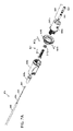
撮像プローブ100は、引き延ばされた本体を有して成り、1つまたはそれより多くの延在シャフトおよび/またはチューブ、本明細書にて延在シャフト120、を有する。シャフト120は、近位端1201と、遠位端1209と、その間に延在するルーメン(lumen)1205と、を有する。ある実施の形態では、ルーメン(lumen)1205は、1つまたはそれより多くの延在シャフト120内に複数の同軸ルーメン(lumens)を、例えば、1つのルーメン(lumen)1205を規定するため互いに当接した1つまたはそれより多くのルーメン(lumen)を含む。シャフト120は、さらに、遠位部分1208を有する。図2および図2A-Cを参照して、シャフト120の構造は以下に説明される。シャフト120は、回転可能な光学ファイバ、近位端1101および遠位端1109を有する光学コア110(例えば、光学コア110はルーメン(lumen)1205内に配置される)を囲む。光学アセンブリ、光学アセンブリ115、は光学コア110の遠位端1109に配置される。コネクタアセンブリ、コネクタアセンブリ150、はシャフト120の近位端に配置される。コネクタアセンブリ150は、撮像プローブ100を回転アセンブリ500に、本明細書に説明するように、操作的に取り付ける。コネクタアセンブリ150は光学コネクタ161を囲みおよび光学コネクタ161にコネクタアセンブリ150を操作的に取り付ける。光学コネクタ161を光学コア110の近位端に固定的に取り付ける。ある実施の形態では、光学コネクタ161を含むコネクタアセンブリ150は図3および図3A-Gを参照した以下で説明されるものと同様な構造および配置であってもよい。第2コネクタ、プルバック(pullback)コネクタ180、はシャフト120上に配置される。コネクタ180は、シャフト120の長さに沿って、外せるように取り付けておよび/または調整可能なように配置されてもよい。例えば、デリバリカテーテル80を通じて患者内に撮像プローブ100が挿入された後のデリバリカテーテル80の近位端に近位は操作者の辺に、シャフト120の長さに沿って、コネクタ180は配置されてもよい。シャフト120は、コネクタアセンブリ150とコネクタ180の配置位置との間の、シャフト120、シャフト120の近位部分(例えば、撮像プローブ100の近位部分)、サービスループ185の緩みに対応する部分を有してもよい。
撮像プローブ100は、その長さに沿って、1つまたはそれより多くの視認できるマーカー、マーカー131a-b(本明細書にて、マーカー131)を有してもよい。マーカー131は次のグループから選定されたマーカーを有してもよい。グループは、放射線不透明なマーカー;超音波反射マーカー;磁性マーカー;鉄製材料;およびこれらの組み合わせからなる。ある実施の形態では、マーカー131は、プルバック(pullback)処置を行う際に撮像システム10の操作者を補助するため、ある位置に(例えば、遠位端1208の中または少なくとも近位な位置に)配置されたマーカーを有する。マーカー131は、例えば、プルバック(pullback)完了後(例えば、プルバック(pullback)後、撮像プローブ100がインプラント内を安全に推進できるように)、インプラントの近位端に対して遠位な位置に先端119を配置することを引き起こす。
回転アセンブリ500は、回転ジョイント550に操作的に取り付けられたコネクタアセンブリ510を有する。回転アセンブリ500は、さらに、モータまたは他の回転エネルギ源、動力構成530、と有する。動力構成530は連結アセンブリ540を通じて回転ジョイント550と操作的に取り付けられる。ある実施の形態では、連結アセンブリ540は1つまたはそれより多くのギア、ベルト、プーリまたは他の力の伝達機構、例えば、図5A-Dを参照して以下で説明するもの、を有する。動力構成530は、回転ジョイント550(およびすなわちコア110)を少なくとも100回転/毎秒の速度で、例えば、少なくとも200回転/毎秒または250回転/毎秒または20回転/毎秒と1000回転/毎秒との間で、駆動する(例えば、連結アセンブリ540を通じて回転させる)ことができる。動力構成530は次のグループから選定された機構を有してもよい。グループは、モータ;サーボ;ステップモータ(例えば、ギアボックスを含むステップモータ);リニアアクチュエータ;中空モータ;およびこれらの組み合わせからなる。
Rotating
コネクタアセンブリ510を、撮像プローブ100のコネクタアセンブリ150に操作的に取り付けることで、光学コネクタ161が回転ジョイント550と操作的に係合できる。ある実施の形態では、図5A-Dを参照して以下に説明するように、コネクタアセンブリ510はコネクタアセンブリ150と操作的に係合する。ある実施の形態では、回転ジョイント550および光学コネクタ161が係合されたアセンブリ内で自由に回転可能なように、コネクタアセンブリ510はコネクタアセンブリ150と操作的に係合する。
The
格納アセンブリ800は、患者に相対的に格納アセンブリ800のための基準を確立するため、基準点に、例えば、デリバリカテーテル80のコネクタ82に操作的に取り付けるコネクタアセンブリ820を有する。コネクタアセンブリ820を基準点に、例えば、患者導入デバイス、手術台および/または他の固定のまたは準固定の基準点に取り付けられる。格納構成、プラー850を、撮像プローブ100のコネクタ180に、例えば、キャリア855を通じて、外せるように取り付ける。確立された基準点に対して、格納アセンブリ800は、撮像プローブ100の少なくとも一部を(例えば、取り付けられたコネクタ180に遠位な撮像プローブ100の部分を)格納する。撮像プローブ100のサービスループ185は、格納アセンブリ800および/または少なくともコネクタアセンブリ820および回転アセンブリ500との間に配置されてもよい。よって、回転アセンブリ500が静止したままである間(例えば、手術台におよび/またはコンソール50の一部に取り付けられた)、患者に対して撮像プローブ100を格納できる。
格納アセンブリ800は、さらに、リニアドライブ(linear drive)、動力構成830を有する。ある実施の形態では、動力構成830は、リニアアクチュエータ、モータに操作的に取り付けられたワームギア、プーリ機構および/または他の力の伝達機構を有する。ある実施の形態では、動力構成830は、図9を参照して以下で説明される動力構成830と同様な構造および配置であってもよい。プラー850は連結アセンブリ890を通じて動力構成830に操作的に取り付けられてもよい。ある実施の形態では、連結アセンブリ890は、図1A、図7A-Cおよび図8A-Cを参照して以下で説明される「プルバック(pullback)アセンブリ」の1つまたはそれより多くの要素を有する。あるいはまたは加えて、連結アセンブリ890は、図1Bおよび図10A-Bを参照して以下で説明される囲まれたプルバック(pullback)コネクタの1つまたはそれより多くの要素を有してもよい。連結アセンブリ890の1つまたはそれより多くの要素は、プラー850と動力構成830との間に基準系を(例えば、内部のプルバック(pullback)基準を)確立させてもよい。よって、動力構成830は連結アセンブリ890を通じてプラー850にプルバック(pullback)力を作用させ、以下で説明されるように連結アセンブリ890の遠位部分に対して(例えば、外装895の遠位端に対して)プラーは格納する。ある実施の形態では、連結アセンブリ890の遠位端とコネクタアセンブリ820とは互いに対して固定されている。動力構成830から受けた力に応じて、プラー850はその2つの間を直線状に移動する。
コンソール50は、撮像アセンブリ300、ユーザーインターフェース55および1つまたはそれより多くのアルゴリズム51を有する。撮像アセンブリ300は、(例えば、光学コア110を通じて)光学アセンブリ115に光を供給するおよび(例えば、光学コア110を通じて)光学アセンブリ115から光を収集するよう構成されてもよい。撮像アセンブリ300は、光学アセンブリ115に光を供給するために構成された光源310を含んでもよい。光源310は、1つまたはそれより多くの光源、例えば、光学コア110を通じて1つまたはそれより多くの波長の光を光学アセンブリ115に充てるように構成された1つまたはそれより多くの光源を有してもよい。光源310は、画像データを収集することができる(例えば、反射された光は、光学アセンブリ115から戻った光を収集し分析するように構成された光学アセンブリ115の光学電気モジュールによって収集される)ように、光学アセンブリ115に(例えば、光学コア110を通じて)光を供給するように構成されている。収集された画像データは、撮像される患者の位置および/または埋め込まれたデバイスに関連した断面の、長手方向のおよび/または体積の情報を有してもよい。光源310は、収集された画像データが撮像されている患者の位置内の組織の特徴を含むように、例えば、定量化する、定性化する、または、撮像されている患者の位置内に存在する患者の病気また障害に関連する情報を提供するように、光を供給するように構成されてもよい。光源310はブロードバンドの光を供給するように構成されてもよく、および、800nmから1700nmの範囲内、例えば、1280nmから1310nm、または、例えば、約1300nm(例えば、1250nmから1350nmの波長掃引範囲を有して供給された光)の中央波長を有してもよい。撮像システム10の意図された使用の要求によって異なり得る望ましい分解能を実現するために、光源310のバンド幅は選定されてもよい。ある実施の形態では、バンド幅が中央波長の約5%から15%であり、これは5ミクロンから20ミクロンの間の分解能が実現する。光源310はANSIクラス1(「目に安全」)の制限を満たすパワー水準で光を供給するように構成されてもよい。より高いパワー水準を適用してもよい。ある実施の形態では、光源310は、約20mWのパワー水準で1.3μmのバンドの光を供給する。供給された光の中央波長が増加し体組織の水分による光吸収が増加すると、組織の光散乱は抑制される。これら2つの作用をつり合わせるため、光源310は約1300nmの波長の光を供給できる。大量の流体を含む撮像される患者の位置を横切るために、より短い波長の光(例えば、約800nmの光)を供給するように光源310は構成されてもよい。あるいはまたは加えて、例えば、撮像される患者の位置内の高い水準の散乱を抑制するために、より長い波長の光(例えば、約1700nmの光)を供給するように光源310は構成されてもよい。ある実施の形態では、光源310は波長可変光源(例えば、光源310は時間とともに繰り返し変化する1つの波長を放出する)および/またはブロードバンドの光源を有する。光源310は1つの空間モードの光源またはマルチモードの光源(例えば、空間フィルタを有するマルチモード光源)を有してもよい。
コンソール50はアルゴリズム、例えば、示されたアルゴリズム51を有してもよい。撮像システム10の1つまたはそれより多くの操作的なパラメータ、例えば、コンソール50の、撮像プローブ100および/またはデリバリカテーテル80の操作的なパラメータを調整する(例えば、自動的におよび/または準自動的に調整する)ように、アルゴリズムは構成されてもよい。あるいはまたは加えて、別のデバイス、例えば、以下で説明されるインジェクタ20またはインプラントデリバリデバイス30の操作的なパラメータを調整するように、アルゴリズム51は構成されてもよい。ある実施の形態では、1つまたはそれより多くのセンサの信号、例えば、本明細書にて説明される本発明のコンセプトのセンサに基づいた機能的な構成によって提供されたセンサの信号に基づいて操作的なパラメータを調整するように、アルゴリズム51は構成される。アルゴリズム51は、次のグループから選定された操作的なパラメータを調整するように構成されてもよい。グループは、光学コア110および/または光学アセンブリ115の回転速度等の回転パラメータ;格納速度、距離、開始位置、終了位置および/または格納の開始時期等のシャフト120および/または光学アセンブリ115における格納パラメータ;光学アセンブリ115の位置等の位置パラメータ;フレーム当たりのライン等のライン間隔パラメータ;血管直径に対する表示の大きさのスケール変換等の画像表示パラメータ;撮像プローブ100の構成パラメータ;生理食塩水から適切な屈折率を特定するように構成されたコントラスト比等のインジェクテート(injectate)21のパラメータ:供給されたパワーおよび/または光の周波数等の光源310のパラメータ;およびこれらの組み合わせからなる。ある実施の形態では、格納パラメータ、例えば、プルバック(pullback)の開始をトリガーするパラメータを調整するようにアルゴリズム51は構成される。プルバック(pullback)は、例えば、次のグループから選定されたパラメータに基づいて開始されるプルバック(pullback)である。グループは、ルーメン(lumen)のフラッシング(画像の作成を妨害する血液または他の物質から光学アセンブリ115に近位なルーメンが充分に洗浄された);インジェクタ20からよりインジケータ(indicator)信号(例えば、充分なフラッシング流体が供給されたことを示す信号)が受信される;収集された画像データにおける変化(例えば、収集された画像データに基づいて、画像の変化が探知され、それは光学アセンブリ115の周辺からの血液の排出に相関する);およびこれらの組み合わせと、からなる。ある実施の形態では、撮像プローブ100に関連した撮像システム10の構成パラメータを調整するように、アルゴリズム51は構成される。例えば、アルゴリズム51が撮像プローブ100を特定し、撮像システム10のパラメータ、例えば、アームパスの長さパラメータ、拡散パラメータおよび/または上記の他のパラメータを調整する。
撮像システム10は1つまたはそれより多くのインターコネクト(interconnect)ケーブル、図示されたバス58を有してもよい。回転アセンブリ500をコンソール50に、格納アセンブリ800をコンソール50におよび/または回転アセンブリ500を格納アセンブリ800に、バス58は操作的に接続できる。バス58は1つまたはそれより多くの光学伝達ファイバ、電気伝達ファイバ、流体導管およびこれらの組み合わせを有してもよい。ある実施の形態では、バス58は少なくとも、回転ジョイント550をコンソール50の撮像アセンブリ300に光学的に連結する光学伝達ファイバを有してもよい。あるいはまたは加えて、バス58は、1つまたはそれより多くの動力構成530および830にパワーおよび/または動力の情報を伝達する少なくともパワーおよび/またはデータ伝達ケーブルを有する。
第2撮像デバイス15は、次のグループから選定された1つまたはそれより多くの撮像デバイスを有してもよい。グループは、X線;単一平面または二平面蛍光透視装置等の蛍光透視装置;CTスキャナ;MRI;PETスキャナ;超音波撮像装置;およびこれらの組み合わせと、からなる。ある実施の形態では、臨床医は、プローブ100によって提供された画像とともに撮像デバイス15によって提供された画像を使用する。ある実施の形態では、システム10は、プローブ100によって提供された画像と第2撮像デバイス15によって提供された画像とを組み合わせるための画像処理を設ける(例えば、プローブ100およびデバイス15によって提供されたデータに基づいた同時登録および/またはデジタルに組み合わせた画像)。ある実施の形態では、第2撮像デバイス15は回転血管撮像を実行するように構成されたデバイスを有する。これらの実施の形態では、システム10は、回転血管撮像画像およびプローブ100より派生した画像を含む組み合わせた画像を提供できる。
The
処置デバイス16は、次のグループから選定されたオクルージョン処置デバイスまたは他の処置デバイスを有してもよい。グループは、狭窄または他の血管の収縮を拡張するように構成および配置されたバルーンカテーテル;薬剤溶解性バルーン;吸引カテーテル;ソノリシスデバイス;アテレクトミーデバイス;ステント回収デバイス等の血栓除去デバイス;トレボ(Trevo、商標)ステントリーバ(stentriever);ソリテア(Solitaire、商標)ステントリーバ;リバイブ(Revive、商標)ステントリーバ;エリック(Eric、商標)ステントリーバ;ラザラス(Lazarus、商標)ステントリーバ;ステントデリバリカテーテル;マイクロブレードインプラント;塞栓システム;ウェブ(Web、商標)システム;ルナ(Luna、商標)システム;メディナ(Medina、商標)システム;およびこれらの組み合わせからなる。ある実施の形態では、処置デバイス16が患者内に挿入された後、処置デバイス16に関連したデータを収集するように撮像プローブ100は構成されている。
Treatment device 16 may comprise an occlusion treatment device or other treatment device selected from the following group. The group includes balloon catheters constructed and arranged to dilate stenoses or other vascular constrictions; drug-dissolving balloons; aspiration catheters; sonolysis devices; Solitaire™ Stentriever; Revive™ Stentriever; Eric™ Stentriever; Lazarus™ Stentriever; Embolization system; Web(TM) system; Luna(TM) system; Medina(TM) system; and combinations thereof. In one embodiment,
インジェクタ20は、パワーインジェクタ、注射器ポンプ、蠕動ポンプ、または、放射線不透明な造影剤および/または他の流体等の造影剤を注入するために構成された他の流体デリバリデバイスを有してもよい。ある実施の形態では、造影剤および/または他の流体(例えば、造影剤、生理食塩水および/またはデキストラン)を供給するようにインジェクタ20は構成される。ある実施の形態では、インジェクタ20は、以下で説明するフラッシング処理で流体を供給する。ある実施の形態では、インジェクタ20は、デリバリカテーテル80を通じて造影剤または他の流体を供給する。デリバリカテーテル80は、5Frと9Frとの間のIDを有するデリバリカテーテル80、0.53”と0.70”との間のIDを有するデリバリカテーテル80、または、0.0165”と0.027”との間のIDを有するデリバリカテーテル80である。ある実施の形態では、4Fr程度に小さいデリバリカテーテルを通じて(例えば、遠位注入のため)、造影剤または他の流体は供給される。ある実施の形態では、1つまたはそれより多くのデリバリカテーテル80のルーメン(lumen)を通じて、インジェクタ20は造影剤または他の流体を供給する。この場合、1つまたはそれより多くのデリバリカテーテル80もルーメン(lumen)内に滞在する。ある実施の形態では、インジェクタ20は、2つの非類似の流体を同時におよび/または順次に供給するように構成される。例えば、第1貯蔵器から供給し造影剤の第1濃度を有する第1流体、および、第2貯蔵器から供給しより少ない造影剤を有するまたは造影剤を有していない第2流体を供給する。
Injector 20 may comprise a power injector, syringe pump, peristaltic pump, or other fluid delivery device configured for injecting contrast agents, such as radiopaque contrast agents and/or other fluids. In some embodiments, injector 20 is configured to deliver contrast media and/or other fluids (eg, contrast media, saline and/or dextran). In one embodiment, the injector 20 supplies fluid with a flushing process described below. In one embodiment, injector 20 delivers contrast or other fluid through
インジェクテート(injectate)21は次のグループから選定された流体を有してもよい。グループは、光学的に透明な材料;生理食塩水;可視化できる材料;造影剤;デキストラン;超音波反射材料;磁性体材料;およびこれらの組み合わせ、からなる。インジェクテート(injectate)21は造影剤と生理食塩水を有してもよい。インジェクテート(injectate)21は少なくとも20%造影剤を有してもよい。画像データの収集の間、フラッシング処理が実施されてもよい。例えば、光学アセンブリ115に近位な血液または他の多少不透明な材料(これ以降、非透明材料)を除去するため、1つまたはそれより多くの流体、インジェクテート(injectate)21を(例えば、インジェクタ20または他の流体デリバリデバイスに推進されて)供給する。例えば、光学アセンブリ115とデリバリカテーテルとの間の非透明材料、および/または、光学アセンブリ115と血管壁との間の非透明材料を除去する。よって、光学アセンブリ115から供給された光が、全組織および撮像される他の物体に届き、そこから反射的に戻ることができる。これらのフラッシングの実施の形態では、インジェクテート(injectate)21は、生理食塩水等の光学的透明は材料を有してもよい。以下で説明するように、インジェクテート(injectate)21は1つまたはそれより多くの可視化できる材料を有してもよい。
フラッシング処理の使用の代替としてはまたはそれに加えて、インジェクテート(injectate)21は、第2撮像デバイス15によって観察されるように構成された材料を有してもよい。例えば、インジェクテート(injectate)21が、第2撮像デバイス15によって観察されるように構成された造影剤の材料を有する。この場合の第2撮像デバイス15は、蛍光透視装置または他のX線デバイス;超音波撮像装置を有する第2撮像デバイス15によって観察されるために構成された超音波反射材料;および/またはMRIを有する第2撮像デバイス15によって観察されるように構成された磁性体材料と有してなる。
Alternatively or in addition to using a flushing process, the
インプラント31は1つまたはそれより多くの血管狭窄または動脈瘤を治療するためのインプラント(例えば、一時的なまたは慢性的なインプラント)を有してもよい。ある実施の形態では、インプラント31は次のグループから選定された1つまたはそれより多くのインプラントを有する。グループは、フローダイバータ(flow diverter);パイプライン(Pipeline、商標)フローダイバータ(flow diverter);サーパス(Surpass、商標)フローダイバータ(flow diverter);エンボライゼーションコイル(embolization coil);ステント;ウィングスパン(Wingspan、商標)ステント;覆われたステント;動脈瘤を治療するインプラントおよびこれらの組み合わせ、からなる。
インプラントデリバリデバイス30は、インプラント31を供給するように使用されるカテーテルまたは他の道具を有してもよい。例えば、インプラント31が、自己拡張またはバルーン拡張部分を有する。ある実施の形態では、撮像システム10は、撮像プローブ100、1つまたはそれより多くのインプラント31、および/または、1つまたはそれより多くのインプラントデリバリデバイス30を有する。ある実施の形態では、インプラント31および/またはインプラントデリバリデバイス30が患者内に挿入された後、インプラント31および/またはインプラントデリバリデバイス30に関連したデータを収集するように撮像プローブ100は構成される。例えば、図12を参照して以下で説明する。収集されるデータは、例えば、インプラント31および/またはインプラントデリバリデバイス30の生体構造における位置、向きおよび/または他の構成データである。
ある実施の形態では、1つまたはそれより多くのシステムの要素、例えば、コンソール50、デリバリカテーテル80、撮像プローブ100、回転アセンブリ500、格納アセンブリ800、治療デバイス16、インジェクタ20、および/またはインプラントデリバリデバイス30は、さらに、1つまたはそれより多くの機能的な構成(本明細書にて、機能的な構成)を有する。例えば、図示された、それぞれの機能的な構成59、89、199、599、899、99a、99b、および/または99cを有する。それぞれの機能的な構成は、少なくとも2つの構成を有してもよい。それぞれの機能的な構成は、センサと、トランスデューサと、これらの組み合わせからなるグループから選定された1つまたはそれより多くの構成を有してもよい。機能的な構成は、信号を出すように構成されたセンサを有してもよい。機能的な構成は、次のグループから選定されたセンサを有してもよい。グループは、生理的センサ;圧力センサ;ひずみゲージ;位置センサ;GPSセンサ;加速度計;温度センサ;磁性体センサ;化学的センサ;生化学的センサ;タンパク質センサ;超音波流体センサ等の流体センサ;超音波気泡探知器等のガス探知センサ;超音波センサ等の音センサ;およびこれらの組み合わせからなる。センサは、次のグループから選定された生理的センサを有してもよい。グループは;血圧センサ等の圧力センサ;血液気体センサ;血流センサ等の流体センサ;血液または他の組織の温度センサ等の温度センサ;およびこれらの組み合わせからなる。センサは、血管パス形状(例えば、2次元または3次元の血管パス形状)に関連する信号を出すように構成された位置センサを有してもよい。センサは、磁性体センサを有してもよい。センサは流体センサを有してもよい。システムは、さらに、センサに基づいた機能的な構成が出した信号を処理するように構成されたアルゴリズムを有してもよい。それぞれの機能的な構成は1つまたはそれより多くのトランスデューサを有してもよい。それぞれの機能的な構成は次のグループから選定された1つまたはそれより多くのトランスデューサを有してもよい。グループは、組織を除去するよう充分な熱を供給できるように構成された加熱構成等の加熱構成;組織を除去するよう充分な冷熱エネルギを供給できるように構成された冷却構成等の冷却構成;超音波トランスデューサ等の音トランスデューサ;振動トランスデューサ;およびこれらの組み合わせからなる。
In some embodiments, one or more system elements such as
本明細書にて説明するように、格納アセンブリ800および回転アセンブリ500は、それぞれ格納操作および回転操作を独立して実行するように構成および配置されてもよい。例えば、光学コア110の同時回転とともにまたは無しで、格納アセンブリ800は、少なくとも撮像プローブ100の一部を独立して格納するように構成されてもよい。撮像プローブ100の同時格納とともにまたは無しで、回転アセンブリ500は、光学コア110を独立して回転させるように構成されてもよい。あるいはまたは加えて、格納アセンブリ800および回転アセンブリ500は、独立して配置できる個別の(分離した)要素を有してもよい。例えば、格納アセンブリ800は、回転アセンブリ500に引張力および/または他の力を作用させないように構成および配置されてもよい(例えば、格納アセンブリ800は、プローブ100の格納の間、回転アセンブリ500が格納するまたは動くことを起こさないまたは要しない)。あるいはまたは加えて、回転アセンブリ500は、格納アセンブリ800に回転力および/または他の力を作用させないように構成および配置されてもよい(例えば、回転アセンブリ500は、光学コア110の回転の間、格納アセンブリ800が格納するまたは動くことを起こさないまたは要しない)。
As described herein,
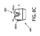
図1Aを参照すると、図1Aには撮像システムの模式図が示されている。システムは、本発明のコンセプトに基づいて、患者インターフェースモジュールに操作的に取り付けることができる撮像プローブを有する。さらに、システムは、本発明のコンセプトに基づいて、患者インターフェースモジュールおよび撮像プローブに操作的に取り付けることができる独立したプルバック(pullback)モジュールを有する。撮像システム10は患者インターフェースモジュール200を有してもよい。患者インターフェースモジュール200は、少なくとも回転アセンブリ500の一部および少なくとも格納アセンブリ800の一部を囲むハウジング、ハウジング201を有する。撮像システム10は、さらに、第2個別要素、プルバック(pullback)モジュール880を有してもよい。プルバック(pullback)モジュール880は、少なくとも格納アセンブリ800の一部を囲むハウジング、ハウジング881、を有する。本明細書にて説明するコネクタアセンブリ、連結アセンブリ890を通じて、プルバック(pullback)モジュール880および患者インターフェースモジュール200は互いに操作的に取り付けることができる。プルバック(pullback)モジュール880および患者インターフェースモジュール200は、(例えば、それぞれが個別のハウジングを有することを通じて)異なる位置に配置できるよう構成および配置されてもよい。例えば、モジュール880および200を接続する連結アセンブリ890は、2つの位置が少なくとも15cm離れることができるように、少なくとも15cmの長さを有してもよい。例えば、患者インターフェースモジュール200は、手術台のレールの上にまたは近くに配置されてもよい。プルバック(pullback)モジュール880は、患者の血管のアクセス位置(vascular access site)の近く(例えば、撮像プローブ100が通じて患者に入る血管のアクセス位置(vascular access site)の30cm以内)に配置されてもよい。連結アセンブリ890は、外装895内に滑りながら受ける連結891を有してもよい。連結891を、プラー893に操作的に取り付ける。連結891の近位端893は接続点842を有してもよい。図1Aに示す要素は、上記の図1でまたは本明細書の他の記載で説明した類似の要素と同様な構成および配置であってもよい。
Referring to FIG. 1A, FIG. 1A shows a schematic diagram of an imaging system. A system has an imaging probe operatively attachable to a patient interface module in accordance with the concepts of the present invention. Additionally, the system has a separate pullback module that can be operatively attached to the patient interface module and the imaging probe in accordance with the concepts of the present invention.
プルバック(pullback)モジュールおよびその関連した要素が、図7A-8Cを参照して以下で説明するプルバック(pullback)モジュール880と同様な構成および配置であってもよい。ハウジング881およびその関連した要素が、図8A-8Cを参照して以下で説明するハウジング881と同様な構成および配置であってもよい。コネクタアセンブリ845およびその関連した要素が、図7A-7Bを参照して以下で説明するコネクタアセンブリ845と同様な構成および配置であってもよい。プルバック(pullback)モジュール880は、図8A-Cを参照して以下で説明するように、デリバリカテーテル80のコネクタ82に操作的に取り付けるコネクタアセンブリ820bを有してもよい。コネクタアセンブリ845は、図4A-Cを参照して以下で説明するように、患者インターフェースモジュール200のコネクタアセンブリ820aに操作的に取り付けるコネクタ840を有してもよい。撮像プローブ100は、図4A-Cを参照して以下で説明するように、患者インターフェースモジュール200のコネクタアセンブリ510に操作的に取り付けるコネクタアセンブリ150を有してもよい。
The pullback module and its associated elements may be configured and arranged similarly to the
図1Bを参照すると、撮像システムの模式図が示されている。システムは、本発明のコンセプトに基づいて、モジュールに操作的に取り付けることができる撮像プローブを有し、モジュールは、回転動力構成に取り付ける第1コネクタおよび格納動力構成に取り付ける第2コネクタを有する。撮像システム10は、本明細書にて説明する患者インターフェースモジュール200を有してもよい。撮像システム10は、さらに、コネクタモジュール、モジュール410を有してもよい。モジュール410はハウジング、ハウジング411を有する。ハウジング411は、少なくとも格納アセンブリ800の一部、撮像プローブ100のサービスループ185、コネクタアセンブリ150’、および、コネクタ840’を囲む。モジュール410は、撮像プローブ100と連結、プラー850’との両方を患者インターフェースモジュール200に操作的に取り付けられるように構成されてもよい。モジュール410は、図10A-Bを参照して以下で説明するように、モジュール410およびその関連した要素(例えば、ウィンドー(window)485を含むデリバリカテーテル80)と同様な構成および配置であってもよい。図1Bで示す要素は、上記の図1でまたは本明細書の他の記載で説明した要素と同様な構成および配置であってもよい。
Referring to FIG. 1B, a schematic diagram of an imaging system is shown. A system, in accordance with the concepts of the present invention, has an imaging probe operatively attachable to a module, the module having a first connector for attachment to a rotary power arrangement and a second connector for attachment to a retraction power arrangement. The
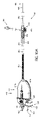
図2を参照すると、本発明のコンセプトに基づいて、光学プローブの模式図が示されている。撮像プローブ100は、その長さに沿って1つまたはそれより多くの延在シャフトを含み、光学コア110を囲む延在本体を有してもよい。例えば、光を伝達するように構成された光学ファイバを有する回転可能なコアを有してもよい。併せて、1つまたはそれより多くの延在シャフトは本明細書にてシャフト120と呼ぶ。光学コア110は非ゼロ分散シフト(NZDS)ファイバ(non-zero dispersion shifted fiber)を有してもよい。例えば、約1300nmの自然ゼロ分散から、ファイバの分散がシフトされたファイバを有してもよい。これらの実施の形態では、撮像システム10は、光学的に一致した分散を使用して操作できる。この場合、コンソール50内の光学要素の合計分散と、光学コア110(例えば、NZDSファイバ)の分散とが、望まれた操作波長範囲内において一致する。あるいはまたは加えて、アルゴリズム51は、コンソール50と光学コア110との間のいずれの分散の不一致を探知および数値的に修正できる。光学コア110は、純シリカコアおよび低い屈折率または「抑圧」クラッドを有するファイバを有してもよい。光学コア110は、例えば、6mm以下の最小半径において5%未満の伝送損失、および/または、3mm以下の最小半径において30%未満の伝送損失を有する、低曲げ損失ファイバを有してもよい。光学コア110は、放射線耐性ファイバを有してもよい。放射線耐性ファイバは、放射線に基づいた殺菌処理からの放射等の放射後において、その光学伝送特性を維持することができる。ある実施の形態では、撮像プローブ100はEビーム殺菌を用いて殺菌される。これらの実施の形態では、Eビーム殺菌を適用できる(例えば、ダメージを受けない)材料を、光学コア110に使用される材料として選択してもよい。例えば、光学コア110は、Eビーム殺菌を適用できるアクリレートコーティングを有してもよい。光学コア110は、電気通信の用途で使用されるものと同様なシングルモードファイバを有してもよい。光学コア110は130ミクロン未満の直径(例えば、クラッド材を含む直径)、例えば、85ミクロン未満の直径、例えば、約80ミクロンの直径を有してもよい。ある実施の形態では、光学コア110は、少なくとも第1部分、および、少なくとも第2部分を有する。第1部分は、非ゼロ分散シフト(NZDS)ファイバ(non-zero dispersion shifted fiber)および/または抑圧クラッド光学ファイバを有する。第2部分は、異なる光学特性を有する光学ファイバ(例えば、非シフト光学ファイバ)を有する。光学コア110は、120ミクロン以下の外径(例えば、クラッド材を含む)、例えば、80ミクロン以下の外径を有する光学ファイバを有してもよい。ある実施の形態では、光学コア110は、シリカコアを有する。シリカコアは、約6μmの直径、約37μmの厚みを有する円周上のクラッド、および円周上のポリイミドおよび/またはアクリレートコーティング、例えば、約10μmの厚みのコーティングを有する。
Referring to FIG. 2, a schematic diagram of an optical probe is shown based on the concept of the present invention.
コネクタアセンブリ150は、撮像プローブ100の近位部分(例えば、コネクタアセンブリ150で終了する撮像プローブ100の近位部分)に配置する。光学コア110は、コネクタアセンブリ150の光学ファイバコネクタ161に操作的に取り付ける。回転可能な第1シャフト、トルクシャフト105は、光学コア110の近位部分を囲み、コネクタアセンブリ150から第1シャフト遷移点T1まで遠位に延在する。外側の第2シャフト、外側シャフト101は、トルクシャフト105と光学コア110の近位部分を囲み、コネクタアセンブリ150から第1シャフト遷移点T1まで遠位に延在する。トルクシャフト105は、例えば、撮像プローブ100が約300cmの長さを有する時、約100cmの長さを有してもよい。図2Aを参照して以下で説明するように、1つまたはそれより多くの要素(例えば、中間シャフト)は、中間の第3シャフト、シャフト125に、操作的に接続する、接合する、配置するまたは外側シャフト101から遷移するために使用することができる。シャフト125は、第1遷移点から、第2遷移点を通過して、第3遷移点まで遠位に延在する。ある実施の形態では、シャフト125は、他のシャフト125の部分よりも高い柔軟性を有する部分、例えば、螺旋カットまたは他の柔軟性を向上させる特徴を有する部分、図示されたセグメント127、を有する。セグメント127は、第2遷移点から第3遷移点まで遠位に延在する。ある実施の形態では、セグメント127は編み目構造または他の柔軟な構造を有する。
図2Bを参照して以下で説明するように、セグメント127を通じたシャフト125内の流体の流入を抑制するために、1つまたはそれより多くの要素(例えば、外側シャフトまたは外装)はセグメント127を囲んでもよい。さらに、図2Bを参照して説明するように、1つまたはそれより多くの要素(例えば、中間シャフト)は、遠位な第4シャフト、ウィンドー(window)130に、操作的に接続する、接合する、配置するまたはシャフト125から遷移するために使用することができる。ウィンドー(window)130は、第3遷移点から撮像プローブ100の遠位端まで、遠位に延在する。ウィンドー(window)130は長さD3を有してもよい。D3は225mmより大きいおよび/または450mm未満、例えば250mmの長さを有してもよい。
As described below with reference to FIG. 2B, one or more elements (e.g., outer shaft or sheath) extend through
ある実施の形態では、撮像プローブ100は、ウィンドー(window)130の遠位部分に注入された(または製造工程において挿入された)粘性ダンプング(damping)材料、ゲル118を含む。ゲル118は非ニュートン流体、例えば、ずり減粘流体を有してもよい。ある実施の形態では、ゲル118は、500センチポイズより大きい静的粘度、および、静的粘度より小さいせん断粘度を有する。これらの実施の形態では、ゲル118の静的粘度とせん断粘度との比は、1.2:1と100:1の間であってもよい。ゲル118は、光学アセンブリ115を含む光学コア110の遠位部分を囲む。ある実施の形態では、ゲル118は、ウィンドー(window)130内に長さD2挿入される。例えば、D2は、ゲル118の近位端とウィンドー(window)130内のゲル118の遠位端の距離を表す。ある実施の形態では、D2は175mmより大きくおよび/または400mm未満の長さ、例えば200mmの長さを有する。ゲル118は、出願人の同時係属中の2017年10月12日に出願された発明の名称「神経学のためのマイクロ光学プローブ(“Micro-Optic Probes for Neurology”) 」米国特許出願第15/566,041号に説明されたゲルを有してもよい。この出願を引用することによって、この出願の内容は、全ての目的において全て本明細書に組み込まれる。
In one embodiment,
撮像プローブ100は遠位先端部分、遠位先端119を含んでもよい。ある実施の形態では、遠位先端119はバネ先端を有する。バネ先端は、例えば、狭い通路内において、撮像プローブ100の「操縦しやすさ」を向上させるように(例えば、撮像プローブ100の「追跡性」および/または「操縦性」を向上させるように)構成される。ある実施の形態では、先端119は5mmと10mmとの間の長さを有する。あるいはまたは加えて、先端119は、ウィンドー(window)130の遠位開口を封口するように構成されたキャップまたはプラグを有してもよい。ある実施の形態では、先端119は、X線下または蛍光透視装置下における撮像プローブ100の見やすさを向上させるため構成された放射線不透明なマーカーを有する。ある実施の形態では、先端119は、「急速取り換え」タイプの先端を有する。
ある実施の形態では、少なくとも撮像プローブ100の遠位部分(例えば、シャフト120の遠位部分)は0.020”以下または0.016”以下の外径を有する。 In some embodiments, at least the distal portion of imaging probe 100 (eg, the distal portion of shaft 120) has an outer diameter of 0.020″ or less, or 0.016″ or less.
ある実施の形態では、撮像プローブ100は、神経血管内の処置で使用するように構成および配置されてもよい。例えば、血液、血管系および他の脳に近位な組織が可視化される処置、および/または、脳に近位に一時的にまたは永久的に配置されたデバイスが可視化される処置で使用する。神経の処置に使用する撮像プローブ100の寸法は次のようであってもよい。撮像プローブ100は約300cmの全体長さL1を有してもよい。外側シャフト101は、コネクタアセンブリ150から遷移点T1まで、約100cmの長さD5で延在してもよい。ある実施の形態では、D5は10cmより大きくおよび/または150cm未満の長さを有する。遷移点T1からT2まで、長さD6は約175cmの長さを有してもよい。D6は1250mmより大きくおよび/または2000mm未満の長さ、例えば、1525mmの長さを有してもよい。遷移点T2からT3まで、長さD4(セグメント127の長さ)は、10mmより大きくおよび/または50mm未満の長さ、例えば、25mmの長さを有してもよい。
In some embodiments, the
あるいはまたは加えて、撮像プローブ100は心臓血管内の処置で使用するように構成および配置されてもよい。例えば、血液、血管系および他の心臓に近位な組織が可視化される処置、および/または、心臓に近位に一時的にまたは永久的に配置されたデバイスが可視化される処置で使用する。心臓血管内の処置に使用する撮像プローブ100の寸法は次のようであってもよい。撮像プローブ100は、少なくとも220cmの全体長さL1、例えば、約280cmの全体長さL1を有してもよい。ある実施の形態では、L1は2600mmより大きくおよび/または3200mm未満の長さを有する。外側シャフト101は、コネクタアセンブリ150から遷移点T1まで、約100cmの長さでD5延在してもよい。遷移点T1からT2まで、長さD6は約155cmの長さを有してもよい。遷移点T2からT3まで、長さD4(セグメント127の長さ)は、約10mmの長さを有してもよい。ある実施の形態では、D4は10mmより大きくおよび/または50mm未満の長さを有する。
Alternatively or additionally,
図2Aを参照すると、本発明のコンセプトに基づいて、図2のセクション1の拡大図が示されている。セクション1は撮像プローブ100の遷移T1を示す。次に、第1直径のシャフト、外側シャフト101からシャフト120に遷移するために構成および配置された要素のセットを説明する。外側シャフト101は、より小さい直径のシャフト、中間シャフト125にトルクシャフト105を囲む。中間シャフト125は、トルクシャフト105の終了後に光学コア110を囲む。外側シャフト101は、シャフト125より高い剛性、異なる材料、および/または、他の異なる物理的特徴を有してもよい。説明された要素は、以下で説明するように、トルクシャフト105の遠位端を光学コア110に操作的に取り付ける。あるいは、遷移T1を実現するためには様々な他の要素を用いてもよい。光学コア110はコーティング111を有してもよい。コーティング111は、クラッド、例えば、光学デザインの分野において能力を有する者に知られた光学クラッド、ポリイミドコーティング等の保護コーティング、および/または、これらの組み合わせを有してもよい。
Referring to FIG. 2A, an enlarged view of
光学コア110を囲むトルクシャフト105は、撮像プローブ100の近位端から約100cm離れたT1で終了する。トルクシャフト105は外側シャフト101内で回転するように構成され、その2つの間で回転力を伝達するために光学コア110に固定的に取り付けられている。ある実施の形態では、トルクシャフト105は、1つの方向に(一方向に)回転するように構成および配置される。あるいは、トルクシャフト105は、いずれの方向に(二方向に)回転するように構成および配置されてもよい。位置合わせ回転構成、チューブ106は、トルクシャフト105の遠位部分と光学コア110との間に配置される(例えば、光学コア110を滑りながら受けて、トルクシャフト105によって滑りながら受けられる)。チューブ106はトルクシャフト105の遠位端より先に延在する。結合107、例えば、エポキシまたはUV接着剤を有する結合は、光学コア110および/またはトルクシャフト105にチューブ106を固定的に取り付ける。あるいはまたは加えて、プレスまたは他の摩擦結合は、光学コア110および/またはトルクシャフト105にチューブ106を固定的に取り付ける。中間の「遷移」チューブ、チューブ122は、図示されるように、外側シャフト101とシャフト125との間に配置される。チューブ122は、外側シャフト101の遠位部分内に滑りながら受けられる。シャフト125の近位部分は、チューブ122の遠位部分(と外側シャフト101)内に滑りながら受けられる。ある実施の形態では、例えば、接着剤および/または摩擦結合を通じて、シャフト101、125およびチューブ122は互いに固定的に取り付けられている。ある実施の形態では、外側シャフト101の遠位端はチューブ122の遠位端より先に延在する。第2位置合わせ構成、チューブ121は、シャフト125の近位端と隣接するように、チューブ122内に配置されてもよい。ある実施の形態では、チューブ106はチューブ122に対して回転しない。チューブ106の遠位端は、チューブ122の近位部分に滑りながらおよび回転しながら受けられ、チューブ121と摩擦的に隣接する。チューブ121は、チューブ121とチューブ122との間の摩擦を最小にするために選定された材料を有してもよい。チューブ121、106および122は、シャフト125にトルクシャフト105を回転的に取り付けることができるよう、回転タイプのジョイントを形成する。チューブ121および106は、トルクシャフト105および/または光学コア110がシャフト125内で遠位に移動することを防止するために隣接する。
The
図2Aには、撮像プローブ100の様々な要素のおよび/または要素の間の複数の寸法を示す。チューブ107は長さD7を有してもよい。撮像プローブ100は長さD8を有する隙間を有してもよい。D8は、トルクシャフト105の遠位端とチューブ122の近位端との間の長さを表す。チューブ122はチューブ106と、重なり長さD9で重なってもよい。チューブ121は長さD10を有してもよい。チューブ122は長さD11を有してもよい。
FIG. 2A shows multiple dimensions of and/or between various elements of
ある実施の形態では、D7は5mmより大きい長さおよび/または、50mm未満の長さ、例えば、20mmの長さを有する。D8は1mmより大きくおよび/または10mm未満の長さ、例えば、5mmの長さを有してもよい。重なり長さD9は3mmより大きくおよび/または30mm未満の長さ、例えば、5mmの長さを有してもよい。D10は3mmより大きくおよび/または30mm未満の長さ、例えば、5mmの長さを有してもよい。重なり長さD11は10mmより大きくおよび/または100mm未満の長さ、例えば、25mmの長さを有してもよい。 In some embodiments, D7 has a length greater than 5 mm and/or a length less than 50 mm, such as 20 mm. D8 may have a length greater than 1 mm and/or less than 10 mm, for example a length of 5 mm. Overlap length D9 may have a length greater than 3 mm and/or less than 30 mm, for example a length of 5 mm. D10 may have a length greater than 3 mm and/or less than 30 mm, for example a length of 5 mm. Overlap length D11 may have a length greater than 10 mm and/or less than 100 mm, for example a length of 25 mm.
図2Bを参照すると、本発明のコンセプトに基づいて、図2のセクション2の拡大図が示されている。セクション2は撮像プローブ100の遷移T2、T3を示す。次に、シャフト120を、第1柔軟性を有する第1部分から、(遷移点T2において)第2柔軟性を有する第2部分に、および、第1材料を有する第1シャフト(シャフト125)から第2材料(光学的透明な材料を有するウィンドー(window)130)を有する第2シャフトに遷移するように構成および配置された要素のセットについて説明する。あるいは、遷移T2およびT3を実現するために様々な他の要素を用いてもよい。
Referring to FIG. 2B, an enlarged view of
遷移T2で、第1柔軟性からより大きい第2柔軟性にシャフト125を遷移させる、シャフト125のセグメント127が開始する。セグメント127は、柔軟性を向上させる「特徴」、例えば、次のグループから選定されたシャフト125のセグメント127に適用された改造を有してもよい。グループは、(図示された)螺旋カット;波形の構造;1つまたはそれより多くのリリーフカット;1つまたはそれより多くの開口;外壁のthinning;およびこれらの組み合わせからなる。ある実施の形態では、セグメント127の改造は、シャフト125に入るおよび/または出る1つまたはそれより多くの通路(例えば、開口)を形成する。例えば、体液および/または他の不純物がシャフト125に入るおよび/または出ることができるような通路を形成する。あるいはまたは加えて、セグメント127の改造は、シャフト125の柱および/または他の構造上の強度を減少させることができる。カバー、チューブ129をセグメント127上において滑りながら受けてもよい。不純物の流入および/またはセグメント127を構造上補強するように、チューブ129は構成される。チューブ129は、柔軟な材料、例えば、シャフト125のセグメント127よりも柔軟な材料を有してもよい。
At transition T2,
シャフト125はT3で終了する。カバー、例えば、図示されたチューブ129、または、別のカバーは遷移点T3を囲んでもよい。チューブ129は、例えば、セグメント127が、シャフト120へまたはシャフト120から流入および/または流出を実現することもあるような螺旋カットを有する時、セグメント127の周りにシールを設けることができる。あるいはまたは加えて、シャフト125のセグメント127は柔軟な材料(例えば、シャフト125の他の部分よりも大きい柔軟性を有する材料)、例えば、ポリマーを有してもよく、金属製および/または非金属性の編み目を含む編み目構造等の編み目構造を有してもよい。ウィンドー(window)130は遷移T3で開始する。光学コア110は、シャフト125およびウィンドー(window)130の両方に滑りながら受けられる。光学コア110は、シャフト125の遠位端を出て、遷移T3でウィンドー(window)130の近位端に入る。チューブ129は、シャフト125の遠位部分の相対位置をウィンドー(window)130の近位部分によって維持する。これは、それぞれの相対的な軸位置(例えば、同軸配置)、および、シャフト125の遠位端に対するウィンドー(window)130の近位端の長手方向の配置(例えば、端部が互いに隣接するまたはほぼ互いに隣接する)を含む。あるいはまたは加えて、ウィンドー(window)130とシャフト125との相対位置を維持するため、他の方法を使用してもよい。例えば、ウィンドー(window)130とシャフト125とを接合するおよび配置するために使用できる製造工程における方法、例えば、リフローはんだ付け工程、溶接工程、および/またはスプライシング(splicing)工程を使用してもよい。
図示するように、ゲル118は先端119の近位端から位置T3に近位な位置に配置することができる。この場合、T3はウィンドー(window)130の近位端から遠位な位置である。ゲル118は、(例えば、ウィンドー(window)130の遠位端から)シャフト120に(例えば、製造工程において)注入することができる。よって、(注入が終了した後において)ゲル118の近位端が、先端119の近位端から50mmと500mmとの間の位置に配置される。例えば、先端119の近位端から200mmと250mmとの間の位置(例えば、図2の距離D1+D2)に配置される。
As shown,
図2Bには、撮像プローブ100の様々な要素のおよび/または要素の間の複数の寸法を示す。チューブ129は、セグメント127の近位端より近位的に先に、長さD12延在してもよい。撮像プローブ100は長さD14の隙間を有してもよい。D14はシャフト125の遠位端とウィンドー(window)130の近位端との間の長さを表す。チューブ129は、図示するように、ウィンドー(window)130上に長さD13延在してもよい。
FIG. 2B shows multiple dimensions of and/or between various elements of
ある実施の形態では、D12は5mmより大きいおよび/または20mmより小さい長さ、例えば、10mmの長さを有する。D14は1mmより小さい長さ、例えば、0.2mmより小さい長さ、例えば、シャフト125がウィンドー(window)130と隣接する時等、約0の長さを有してもよい。D13は5mmより大きいおよび/または20mmより小さい長さ、例えば、15mmの長さを有してもよい。
In an embodiment D12 has a length greater than 5 mm and/or less than 20 mm, for example a length of 10 mm. D14 may have a length of less than 1 mm, eg, less than 0.2 mm, eg, a length of about 0, such as when
図2Cを参照すると、本発明のコンセプトに基づいて、図2のセクション3の拡大図が示されている。セクション3は撮像プローブ100の遠位部分を説明する。光学アセンブリ115を、光学コア110の遠位端に操作的に(例えば、光学的に)取り付ける。光学アセンブリ115はウィンドー(window)130内に配置され、その長手方向の軸の回りを回転(例えば、撮像プローブ100内の光学コアとともに回転)できる。ゲル118は、少なくともウィンドー(window)130内の光学アセンブリ115を囲む。ゲル118は、本明細書にて説明するように、ずり減粘流体を有してもよい。遠位先端119は、ウィンドー(window)130の遠位端を「栓をする」(例えば、流出を防止する)ように構成されたシーリング構成1192を有してもよい。例えば、ウィンドー(window)130の遠位端から、ゲル118が流出することを防止する。遠位先端119は、バネ先端(図示されていないが、カテーテルの設計の分野において能力を有する者には知られている)を有してもよい。遠位先端119は、X線および/または蛍光透視装置等の撮像デバイスを使用して少なくとも撮像プローブ100の遠位先端119の視覚性を向上させるように構成された、放射線不透明なまたは他のマーカーを有してもよい。ある実施の形態では、遠位先端119のシーリング構成1192は、図示された角度を有する近位端1191を有する。角度を有する近位端1191は、例えば、光の反射が、レンズ116の遠位端からレンズ116に戻るように漏れることを防止するまたは少なくとも低減する(例えば、レンズ116と遠位先端119の近位端との間の光のカプリングを防止するまたは少なくとも低減する)。近位端1191は、15°と80°との間の、例えば、45°の角度を有する近位端を有してもよい。
Referring to FIG. 2C, an enlarged view of section 3 of FIG. 2 is shown in accordance with the concept of the present invention. Section 3 describes the distal portion of
光学アセンブリ115は、集光構成、レンズ116、例えば、GRINレンズを有してもよい。光学アセンブリ115は、さらに、カバー、外装117、および、レンズ116に遠位に配置された閉口された体積、チャンバ114(例えば、レンズ116の遠位端がチャンバ114の近位端を規定する)を有してもよい。シーリング構成、プラグ113、はチャンバ114の遠位端を規定する。例えば、光学ファイバ設計の分野において一般的である溶接を通じて、レンズ116は光学コア110に光学的に接続することができる。光学コア110のコーティング111(または他のコーティング)は、光学コア110の遠位端の近位において除去することができる。よって、コーティング111は、光学ファイバ接合工程に干渉しない。レンズ116は、300ミクロンより小さい、例えば、250ミクロンより小さいまたは200ミクロンより小さい外径を有してもよい。レンズ116は、0.5mm以上の長さ、例えば、1mm以上の長さを有してもよい。レンズ116は複数の構成を有してもよい。例えば、レンズ116は、レンズ116(例えば、研磨面を有するGRINレンズ)の遠位端に研磨されたまたは他の方法で形成されたビーム偏向器(例えば、レンズ116内へまたはレンズ116外へ光を向けるように構成された反射面)を有する。あるいはまたは加えて、レンズ116は、平面状の遠位端、非球状の遠位端、球状の遠位端および/または円柱状の遠位端を有してもよい。レンズ116の遠位端は、直接的に反射するビーム偏向器(例えば、金属および/または誘電体のコーティングで反射するように塗布されたビーム偏向器)および/または完全に内部反射(例えば、レンズ116内で内部反射)するビーム偏向器を有してもよい。ある実施の形態では、レンズ116は、特定の集光要件を与えるために、および/または、過度なビーム歪みを起こさずに(例えば、意図した光学機能を維持した状態で)、直接レンズ116内に(例えば、製造において)ビーム偏向表面の研磨を実現するように構成されたドーピングプロフィール(doping profile)を有する。ある実施の形態では、レンズ116は0.2未満、例えば、0.18未満の開口数を有する。あるいはまたは加えて、レンズ116は2mm-1未満、例えば、1.7mm-1未満の放物線状のおよび/または2次のドーピングプロフィール(doping profile)定数を有してもよい。外装117はレンズ116、および、少なくともコーティング111を含む光学コア110の遠位部分を滑りながら受けることができる。よって、コーティング111が除去された光学コア110のいずれかの部分は外装117に覆われている。ある実施の形態では、保護材料、フィラー112は、外装117内における光学コア110のクラッド材無しの部分を囲む。フィラー112は、エポキシまたはUV接着剤等の接着剤を有してもよい。接着剤は、光学コア110を保護するよう、および/または、ファイバからの光の漏れの防止を補助するため、光学コア110内の内部反射を増加させるよう構成される。ある実施の形態では、レンズ116の遠位端には、レンズ116内へおよび/またはレンズ116外へ約90°で光を反射させるように構成された内部反射面を設ける。チャンバ114は、大気および/またはガス、例えば、不活性ガスで充填されてもよい。チャンバ114は、ゲル118がレンズ116の遠位端に接触することを防止する保護バリアを設けてもよい。よって、レンズ116とチャンバ114内のガスとの間の屈折率が、レンズ116における内部反射を容易にする。プラグ113は多孔質のシーリング構成を有してもよい。例えば、プラグ113はフィルタ材料、例えば、多孔質のフィルタ材料を有する。フィルタ材料は、チャンバ114内へのゲル118の流入を(例えば、ウィンドー(window)130内へゲル118を注入する製造工程の際に)防止するように、および/または、チャンバ114内において圧力平衡を(例えば、製造工程、殺菌工程または他の工程において)実現させるように構成される。ある実施の形態では、プラグ113は、圧力平衡を実現するため、開口を有するプラグ(例えば、開口を有する非多孔質のプラグ)、チャネル113aを有する。
図2Cに、撮像プローブ100の様々な要素のおよび/または要素の間の複数の寸法を示す。外装117は、重なり長さD15でコーティング111と重なってもよい。光学コア110は、コーティング111が除去された長さD16の部分を有してもよい。レンズ116は長さD17を有してもよい。チャンバ114、長さD18の開口を有してもよい。外装117は、レンズ116の遠位端よりも先に長さD20延在してもよい。プラグ113は長さD19を有してもよい。撮像プローブ100は長さD21の隙間を有してもよい。D21はプラグ113の遠位端とシーリング構成1192との間の長さを表す。シーリング構成1192は長さD1を有してもよい。
FIG. 2C illustrates multiple dimensions of and/or between various elements of
ある実施の形態では、D15は0.5mmより大きいおよび/または10mm未満の長さ、例えば、0.7mmの長さを有する。D16は0.5mmより大きいおよび/または10mm未満の長さ、例えば、0.7mmの長さを有してもよい。D17は0.5mmより大きいおよび/または5mm未満の長さ、例えば、1.1mmの長さを有してもよい。D18は0.2mmより大きいおよび/または5mm未満の長さ、例えば、0.4mmの長さを有してもよい。D19は0.2mmより大きいおよび/または5mm未満の長さ、例えば、0.5mmの長さを有してもよい。D20は0.4mmより大きいおよび/または10mm未満の長さ、例えば、0.9mmの長さを有してもよい。D21は0.5mmより大きいおよび/または10mm未満の長さ、例えば、0.7mmの長さを有してもよい。D1は1mmより大きいおよび/または5mm未満の長さ、例えば、2mmの長さを有してもよい。 In some embodiments, D15 has a length greater than 0.5 mm and/or less than 10 mm, eg, 0.7 mm. D16 may have a length greater than 0.5 mm and/or less than 10 mm, for example 0.7 mm. D17 may have a length greater than 0.5 mm and/or less than 5 mm, for example a length of 1.1 mm. D18 may have a length greater than 0.2 mm and/or less than 5 mm, for example 0.4 mm. D19 may have a length greater than 0.2 mm and/or less than 5 mm, for example 0.5 mm. D20 may have a length greater than 0.4 mm and/or less than 10 mm, for example 0.9 mm. D21 may have a length greater than 0.5 mm and/or less than 10 mm, for example 0.7 mm. D1 may have a length greater than 1 mm and/or less than 5 mm, for example a length of 2 mm.
図3、図3A-D、および、図3E-Gを参照すると、本発明のコンセプトに基づいて、それぞれ、コネクタアセンブリの分解図、4つのアセンブリ図、部分的な断面図、部分的な分解図、および、透視図が示されている。本明細書にて説明するように、コネクタアセンブリ150を、光学プローブ、例えば、撮像プローブ100の近位端に操作的に取り付けてもよい。コネクタアセンブリ150は、撮像プローブ100を回転する光学ファイバコネクタ(例えば、標準的な光学ファイバ回転ジョイント、FORJ)に操作的に取り付ける(光学的におよび機械的に取り付ける)ように構成および配置されてもよい。コネクタアセンブリ150は、係合コネクタと操作的に係合するようにおよび光学ファイバ接続を維持するように構成された光学ファイバコネクタ161を有する。ある実施の形態では、光学ファイバコネクタ161は商業的に入手可能な光学ファイバコネクタ、例えば、SC/APC光学ファイバコネクタ、例えば、電気通信ネットワークで一般的に使用されているものを有する。これらの実施の形態では、本明細書にて説明するように、コネクタアセンブリ150は、1つまたはそれより多くの要素を有してもよい。要素は、コネクタアセンブリ150内の光学ファイバコネクタ161の相対位置および向きを操作的に係合する、操作するおよび/または維持するように構成および配置される。コネクタアセンブリ150は、以下で説明するように、1つまたはそれより多くの位置合わせ要素を含んでもよい。取り付けおよび/または取り外しにおいて、回転アセンブリ500に対する光学ファイバコネクタ161の回転的な向きを維持した状態で、位置合わせ要素を、回転アセンブリ、例えば、本明細書にて説明する回転アセンブリ500、に操作的に取り付ける。
コネクタアセンブリ150は、コネクタの複数の形態、例えば、バイオネット(bayonet)または他のロッキングコネクタを有してもよい。後述では、バイオネット(bayonet)タイプのコネクタを説明する。バイオネット(bayonet)タイプのコネクタは、撮像プローブ100と回転アセンブリ500との間で接続を形成および維持するために必要な力および制限を設けるように構成および配置される。
3, 3A-D, and 3E-G, an exploded view of a connector assembly, four assembly views, a partial cross-section, and a partial exploded view, respectively, according to the concept of the present invention. , and a perspective view are shown. A
コネクタアセンブリ150は回転アセンブリ160と、ロッキングアセンブリ170と、少なくとも回転アセンブリ160およびロッキングアセンブリ170の一部を囲むハウジング、コネクタ本体151とを有する。コネクタアセンブリ150は、保護カバー、スカート154を含んでもよい。スカート154は、本明細書にて説明するように、コネクタアセンブリ150と患者インターフェースモジュール200のコネクタアセンブリ510との間にシールを設けることができる。シールによって、例えば、患者インターフェースモジュール200のハウジング201内への不純物の流入を防止する。回転アセンブリ160は光学コネクタ161を有する。ある実施の形態では、光学コネクタ161は、係合光学コネクタと適切な回転的位置合わせを必要とするコネクタ、例えば、本明細書にて説明する回転アセンブリ500の光学回転ジョイント550を有する。コネクタアセンブリ150は、接続および/切断の際に追加の位置合わせ工程の必要がなく、2つのコネクタの間に適切な位置合わせを設けるように構成および配置されてもよい。よって、いずれの使用者による(例えば、手動の)および/またはシステム上の位置合わせ工程の必要がなくなる。光学コネクタ161は、さらに、連結シャフト、シャフト169を有する。光学コネクタ161(連結シャフト169を含む)は、光学コア110の近位端およびトルクシャフト105(図示していない)を滑りながら受ける。トルクシャフト105および/または光学コア110を、光学コネクタ161に(例えば、連結シャフト169を通じて)操作的に取り付けることができる。よって、光学コネクタ161よりトルクシャフト105および/または光学コア110に回転力が作用する。例えば、光学コネクタ161の回転が、トルクシャフト105および/または光学コア110を回転させる。ある実施の形態では、回転アセンブリ160は、光学コア110を1つの方向に(一方向に)回転させるよう構成される。あるいは、回転アセンブリ160は、光学コア110をいずれの方向に(二方向に)回転させるよう構成される。光学コア110の近位端は光学コネクタ161内に配置される。よって、光学コア110の近位端が、光学コネクタ161の近位端と揃えられ、第1光学伝達表面161aを形成する。第1光学伝達表面161aは、光学接続を形成するため、(例えば、係合光学コネクタの)第2光学伝達表面555と隣接するように構成される。ある実施の形態では、第1および第2光学伝達表面161a、555は、接続を通じて伝送される光の量を増加させるため、それぞれ面取り部を有してもよい。光学コネクタ161は、非対称輪郭を有する非円形の形状(例えば、図示する長方形)を有してもよい。よって、光学コネクタ161は、(例えば、面取りされた光学伝達表面が適切に揃えた)特定の揃った向きにおいてのみ、第2コネクタ係合できる。回転アセンブリ160は、円形のハウジング、キャリア163、および、ロッキングコネクタ、クリップ162を含む。クリップ162は、図3Aおよび3Bに示す回転アセンブリ160の2つのアセンブリ図のように、キャリア163内に光学コネクタ161を固定的に維持するように構成される。キャリア163は第1半径方向凹部、スロット164および1つまたはそれより多くの位置合わせ凹部、穴165を有する。キャリア163および/またはクリップ162は、回転アセンブリ160を回転的に安定させるために寸法を決められたおよび配置された1つまたはそれより多くのリリーフ(例えば、開口、スロットおよび/または凹部)および/または突出部を有してもよい。このリリーフおよび/または突出部は、光学コネクタ161または回転アセンブリ160の他の要素の回転的不安定さを補正するように構成されてもよい。例えば、光学コネクタ161は不安定なコネクタであってもよい。完全に組立てたとき、回転アセンブリ160は、振動または高い回転速度における不安定な荷重の他の悪影響を制限するために、回転的に安定している。
ロッキングアセンブリ170は、ハウジング、回転ロック171と、保持機構、1つまたはそれより多くの保持構成を有するコネクタ保持要素175と、突出部176と、バイアス構成、ロッキングバネ179とを備える。
Locking
図3Cおよび3Dを参照すると、コネクタアセンブリ150の一部の対向する部分的な断面図が示されている。回転ロック171は、1つまたはそれより多くの突出部、ロッキング歯172(3つのロッキング歯172a-cが図示される)を有する。回転アセンブリ160は、回転ロック171内に滑りながら受けられる。よって、回転アセンブリ160が回転ロック171内に完全に挿入された時、ロッキング歯172a-cは、キャリア163の穴165(165aおよび165cは図示され、165bは突出部172bと対向して配置される)と滑りながら係合する。この係合は、回転ロック171と回転アセンブリ160との間の回転的向きを固定する。ある実施の形態では、ロッキング歯172は非対象なパターンを有し、穴165も同様な非対称なパターンを有する。よって、キャリア163が完全に回転ロック171内に係合できる(例えば、穴165aおよび突出部172aが独占的に係合するように寸法が決められた)1つの回転的向きがある。あるいはまたは加えて、回転ロック171は、キャリア163を摩擦的に係合するための摩擦板を有してもよい。コネクタ保持要素175は回転ロック171とキャリア163との周りに配置される(例えば、製造工程において、回転ロック171とキャリア163との周りに滑りながら配置される)。よって、突出部176はスロット164内に拘束されており、回転アセンブリ160が回転ロック171から出ることを防止する。スロット164は、突出部176の幅より大きい幅を有してもよい。よって、回転アセンブリ160は、回転ロック171内に長手方向において(例えば、軸上で)移動できる。例えば、ロッキング歯172が穴165から脱離するように、回転アセンブリ160は近位に移動できる。例えば、以下で説明するように、回転ロック171に力が作用する場合、回転ロック171は回転アセンブリ160に対して遠位に移動できる。突出部176は、スロット164の遠位端を操作的に係合でき、回転アセンブリ160が回転ロック171から出ることを防止する。加えて、キャリア163は、ロッキング歯172が穴165を係合し、キャリア163の遠位端が回転ロック171の背面に隣接するように、最も近位な位置から遠位に移動できる。
3C and 3D, opposing partial cross-sectional views of a portion of
図3E-Gを参照すると、コネクタ本体151内に滑りながら受けられた回転およびロッキングアセンブリ160、170が示されている。ロッキングアセンブリ170は、コネクタ本体151内に回転的に固定される。回転アセンブリ160は、穴165にロッキング歯172が係合する場合、ロッキングアセンブリ170に回転的に固定され、したがって、コネクタ本体151にも固定される。それ以外では、回転アセンブリ160はコネクタ本体151内で自由に回転する。ある実施の形態では、コネクタ保持要素175は、コネクタ本体151内に固定的に配置される。回転ロック171は、回転アセンブリ160とともに、コネクタ保持要素175に対して、コネクタ本体151内に「浮遊する」。回転アセンブリ160は、コネクタ保持要素175によって「拘束される」。よって、上記で説明するように、回転アセンブリ160は、最も近位な位置(突出部176がスロット164と係合する位置)と最も遠位な位置(回転アセンブリ160の遠位端が回転ロック171と隣接する位置)との間で、回転および長手方向に移動できる。コネクタアセンブリ150は、さらに、バイアス構成、バネ179を有してもよい。バネ179は、コネクタアセンブリ150の1つまたはそれより多くの要素に、例えば、コネクタアセンブリ150が係合コネクタに接続されていない場合に、バイアスをかけるように構成される。例えば、バネ179は、コネクタ本体151の一部と回転ロック171との間に配置されてもよく、回転アセンブリ160に対して回転ロック171に遠位にバイアスをかける。よって、回転アセンブリ160は、最も近位な位置におけるコネクタ保持要素175に対してバイアスを有する。このバイアスの配置は、穴165からロッキング歯172が脱離することを防止できる。よって、コネクタアセンブリ150が係合コネクタに接続されていない間、回転アセンブリ160とコネクタ本体151との間の相対的回転向きを維持する。あるいはまたは加えて、コネクタアセンブリ150が係合コネクタに接続されている場合、バネ179は係合コネクタから「外へ」コネクタ本体151をバイアスすることができる。よって、図6A-Dを参照して以下で説明するように、1つまたはそれより多くの連結機構を容易にすることを補助する。
Referring to FIGS. 3E-G, the rotating and locking
コネクタ本体151は、係合コネクタと位置合わせおよび係合するための1つまたはそれより多くの突出部を含む。図示されるように、コネクタ本体151が第1突出部、位置合わせマーカー152を有する。図4Aから図6Dまでを参照して説明するように、マーカー152は、係合コネクタにコネクタアセンブリ150を視覚的におよび操作的に位置合わせするために構成される。位置合わせマーカー152は、コネクタ本体151の「上」を示すことができ、光学コネクタコネクタ161の「上」と回転的に位置合わせすることができる。例えば、回転ロック171を通じて、光学コネクタ161がコネクタ本体151に対して回転的にロックされる。コネクタ本体151は、さらに、1つ、2つまたはそれより多くのロッキング突出部、図示された突出部153aおよび153c(突出部153bは図示していないがコネクタ本体151の後ろに配置されている)、を含んでもよい。コネクタアセンブリ150は、さらに、第2本体部分、カバー155、を有してもよい。カバー155は1つまたはそれより多くの係合要素、図示された凹部159a、を有してもよい。凹部159aは、コネクタアセンブリ150の1つまたはそれより多くの係合要素、図示された突出部159bと位置合わせすることで、コネクタ本体151にカバー155を適切に位置合わせするように構成される。カバー155は、指示マーキング、マーキング156、および、1つまたはそれより多くの凹みを有した、輪郭が形成されたまたはエルゴノミックな部分、グリップ157を含んでもよい。グリップ157は、使用者が自然にコネクタアセンブリ150を掴み、係合コネクタにコネクタアセンブリ150を(例えば、マーカー152と156を位置合わせおよび指示のために使用しながら)位置合わせし、接続を固定させるためにコネクタアセンブリ150を挿入およびひねることできるように構成および配置されてもよい。マーキング156は、マーキング152とともに、係合コネクタにコネクタアセンブリ150を係合する工程、例えば、挿入する、押す、回転する、を使用者に示すことができる。
コネクタアセンブリ150は、さらに、コネクタ150と撮像プローブ100の1つまたはそれより多くの要素との間のひずみを低減させるために構成された構成を含んでもよい。図示されるように、撮像プローブ100は、少なくとの光学コア110およびトルクシャフト105を囲む外側の近位シャフト、外側シャフト101を有する。ひずみ解放部158は、コネクタアセンブリ150に固定的に取り付けられた外側シャフト101を滑りながら受ける。光学コアおよびトルクシャフト105は外側シャフト101の中で自由に回転する。
図4A-Cを参照すると、本発明のコンセプトに基づいて、患者インターフェースモジュールに取り付けられたコネクタの2つの透視図、および、外側のケースを外した患者インターフェースモジュールの一部の透視図、がそれぞれ示されている。以下で説明するように、患者インターフェースモジュール200は、撮像プローブの回転可能な光学コアに回転を与えるように、および、少なくとも撮像プローブの一部を移動させる動力を与えるように構成される。患者インターフェースモジュール200は、回転アセンブリ500および少なくとも格納アセンブリ800の一部を有する。ハウジング201は患者インターフェースモジュール200を囲む。患者インターフェースモジュール200は、1つまたはそれより多くのユーザーインターフェース構成、例えば、1つまたはそれより多くの入力、ボタン205a、bおよび1つまたはそれより多くの出力、図示されたインジケータ206、を有してもよい。本明細書にて説明するように、患者インターフェースモジュール200は、コネクタアセンブ150に操作的に取り付けるために、第1物理コネクタアセンブリ、コネクタアセンブ510を有する。本明細書にて説明するように、患者インターフェースモジュール200は、さらに、コネクタ840に操作的に取り付けるために、第2コネクタアセンブリ、コネクタアセンブリ820aを有してもよい。図4Aに示すように、コネクタアセンブリ150およびコネクタ840は、それぞれコネクタアセンブリ510および820aに少なくとも部分的に挿入されるように構成および配置されるバイオネット(bayonet)タイプのコネクタをそれぞれ有してもよい。本明細書にて説明するように、コネクタアセンブリ510および820aとの係合をそれぞれロックさせるため、コネクタアセンブリ150およびコネクタ840を順に回転(例えば、約45°の回転)させることができる。コネクタアセンブリ150および/または840は複数の形態のコネクタ、例えば、バイオネット(bayonet)または他のロッキングコネクタを有してもよい。後述において、撮像プローブ100と回転アセンブリ500との間で接続を形成および維持するために必要な力および制限を設けるために構成および配置されたバイオネット(bayonet)タイプのコネクタについて説明する。
4A-C, two perspective views of a connector attached to a patient interface module and a perspective view of a portion of the patient interface module with the outer case removed, respectively, in accordance with the concepts of the present invention. It is shown. As described below, the
図4Cに示すように、コネクタアセンブリ510は浮遊するロッキング部分、スリーブ515を有する。スリーブ515は1つまたはそれより多くの切り取り部分またはリリーフ、開口517a-c(517bは図示していないが、スリーブ515の周りに、例えば、同等にスリーブ515の周りに配置する)を有する。開口517a-cの遠位辺は設計された形状、ロッキング輪郭518a-c(輪郭518aは図示された)を有する。以下で説明するように(図4Cに図示された突出部153a)、ロッキング輪郭518a-cは、コネクタ本体151の突出部153a-cと操作的に係合するように構成および配置されてもよい。スリーブ515は1つまたはそれより多くの通路、凹部516a-c(図4Cに図示された凹部516a)を有してもよい。凹部516a-cは、コネクタアセンブリ510に挿入される際のコネクタアセンブリ150の適切な位置合わせを保証する。突出部153a-cは、凹部516a-cを通過し、それぞれ開口517a-cに入る。突出部153a-cが開口517a-cに入ると、コネクタアセンブリ150はコネクタアセンブリ510に対して自由に回転できる。
As shown in FIG. 4C,
コネクタ本体151がコネクタアセンブリ510に挿入された後、図4Bで示すようにコネクタアセンブリ150は回転する。突出部153a-cは、ロッキング輪郭518a-cに滑りながら係合する。ロッキング輪郭518a-cは、突出部153a-cが(回転アセンブリ150とともに)回転する際にコネクタアセンブリ510に向かって内側に押されるように構成および配置される。コネクタアセンブリ510は1つまたはそれより多くのバイアス構成、保持構成519を有してもよい。保持構成519は、1つまたはそれより多くの保持構成を有してもよい。例えば、スリーブ515の外周で等間隔に配置された3つの構成を有してもよい。保持構成519は、コネクタアセンブリ510の近位端に向かって、スリーブ515を「内側に」バイアスするために構成および配置されたバネアセンブリを有してもよい。保持構成519は、ロッキング輪郭158a-cに対する突出部153a-cの押す力によって、スリーブ515が外側に移動することを実現する。保持構成519は、ロッキング輪郭518a-cと係合するように回転した際に、スリーブ515がコネクタアセンブリ150に対して予め定められた力を作用させるように構成および配置されてもよい。
After
患者インターフェースモジュール200は、構造上の支持材、フレーム202を有する。フレーム202に、回転アセンブリ500の要素および格納アセンブリ800の要素を取り付けることができる。例えば、患者インターフェースモジュール200内において要素の相対位置を固定するために、フレーム202に直接および/または間接的に取り付ける。図7A-Cを参照して以下で詳細に説明するように、コネクタ840を同様にコネクタアセンブリ820aに取り付けることができる。図9を参照しながら以下で、コネクタアセンブリ820aのある実施の形態について詳細に説明する。
図5および5A-Dを参照して、本発明のコンセプトに基づいて、患者インターフェースモジュールの要素の部分的な切り取り透視図を示す。図5は、コネクタアセンブリ510および820a、および、ハウジング201を取り除いた患者インターフェースモジュール200内の回転アセンブリ500の要素を示す。図5Aおよび5Bはコネクタアセンブリ510に操作的に接続したコネクタアセンブリ150を示す。図5Aには、1つまたはそれより多くの要素の断面を取り、スリーブ515、回転ロック171およびコネクタ保持175が図示される。図5Bには、スリーブ512、回転ロック171およびコネクタ保持175も断面を取り、回転アセンブリ160およびスリーブ512内の係合要素が図示される。図5Cおよび5Dは、光学ファイバ回転ジョイント560を有するアセンブリを図示する。図5Cには、複数の要素の断面が図示され、複数の要素が透明なものとして図示される。図5Dには、複数の要素の断面が図示される。
5 and 5A-D, partial cut-away perspective views of elements of a patient interface module are shown in accordance with the concepts of the present invention. FIG. 5 shows
回転アセンブリ500は光学コネクタ、回転ジョイント550、および、光学ファイバ回転ジョイント、回転ジョイント560を有する。図5Cおよび5Dで図示されるように、回転ジョイント560は固定された部分、ハウジング561を有する。回転部分、スピンドル562はハウジング561に対して回転する。スピンドル562の少なくとも一部はハウジング561内に配置される。回転ジョイント560は1つまたはそれより多くの回転ベアリング、図示されたベアリング563a-bを有してもよい。ベアリング563a-bは、摩擦を抑制し、スピンドル562とハウジング561との間の回転に平坦な界面を提供するように構成される。
The
スリーブ515は、固定された接続構成、スリーブ512を囲む。コネクタ本体151は、スリーブ515と512との間で、(つまり、コネクタアセンブリ150がコネクタアセンブリ510に接続されている際)滑りながら受けられる。コネクタアセンブリ150が、コネクタアセンブリ510内に挿入されると、スリーブ512は回転ロック171と対向し、回転ロック171が予め定められた距離以上近位に(コネクタアセンブリ510のさらに「内側へ」)移動することを防止する。コネクタ本体151がコネクタアセンブリ510内にさらに押し込まれると、回転ロック171によってロッキングバネ179が圧縮される。コネクタアセンブリ510内にさらに押し込まれると、キャリア163に力を作用させるために、バネ179が充分圧縮された時、コネクタ本体151はキャリア163と隣接するように構成されてもよい。例えば、ロッキング輪郭518a-cがコネクタ本体151を前に押すことによって、コネクタ本体151は、コネクタ本体151の回転を通じてスリーブ515内にさらに押し込まれる。コネクタ本体151とキャリア163との間の力によって、光学コネクタ161が容器551と完全に係合することを保証するのに充分な場合もある。
図5をまた参照すると、回転アセンブリ500は動力要素530を有する。動力要素530は、本発明のコンセプトに基づいた少なくとも撮像プローブの一部の並進移動(例えば、格納)を起こすための動力を供給するように構成されてもよい。動力構成530はスピンドル562に回転力を供給するように構成されたモータを有してもよい。動力構成530は力伝達構成、プーリ535を有してもよい。プーリ535はスピンドル562の力伝達構成、ギア511に操作的に取り付ける。プーリ535とギア511とは駆動機構、連結536を通じて操作的に接続することができる。ある実施の形態では、連結536はチェーンまたはたの駆動機構を有する。ある実施の形態では、プーリ535およびギア511は1:2の比等の力および/または速度倍増関係を有する。
Referring also to FIG. 5, rotating
図5Cおよび5Dを参照すると、回転ジョイント550は容器551を有してもよい。容器551は、回転アセンブリ160の光学コネクタ161を滑りながら受けるように構成される。容器551は凹部552を有してもよい。凹部552は、光学コネクタ161が容器551と適切に位置合わせされた場合、光学コネクタ161からの突出部を滑りながら受けるように構成される。回転ジョイント550は「浮遊」部分553を有してもよい。浮遊部分553は、回転ジョイント550への光学コネクタ161の接続の間および/または後の移動(例えば、直線移動)を補正するために構成される。補正は、回転ジョイント550内で軸方向に移動する浮遊部分553によって実現される。浮遊部分553は、容器551の遠位端に対して(例えば、光学コネクタ161に対して)バイアスされてもよい。例えば、浮遊部分553はバイアスバネを含む。ある実施の形態では、回転ジョイント550とコネクタ161との接続の後、結果的に生じる軸方向の力はつり合っている。よって、接続が形成された後、浮遊部分553の軸方向の移動は最小になる。ある実施の形態では、つり合った軸方向の力は(例えば、1つまたはそれより多くの力つり合わせバネのバネ力を調整することで)調整される。よって、光学伝送表面555と161aとの間の力は、光学伝送には充分であり、かつ、光学伝送表面555および/または161aのいずれかにダメージを与える水準より低い。浮遊部分553は、中間光学ファイバ伝送導管、光学ファイバケーブル556を囲み、光学ファイバケーブル556に操作的に取り付けられている。光学ファイバケーブル556は光学伝送表面555で遠位に終了する。光学伝送表面555は、上記で説明するように、光学コネクタ161に接続した場合、光学伝送表面161aと隣接するように構成される。光学ファイバケーブル556の中央部分はスピンドル562内の凹部または他の空間、チャネル554内に配置される。光学ファイバケーブル556は光学ファイバ回転連結、回転カプラ565で近位に終了する。浮遊部分553の直線移動を補正するため、チャネル554は、光学ファイバケーブル556がチャネル554内に降伏(buckle)(例えば、図示された「S」字型に変形)できるように構成および配置されてもよい。チャネル554は、浮遊部分553の最大直線移動を収容するように寸法を決められおよび配置されてもよい。チャネル554は、さらに、光学ファイバケーブル556の降伏(buckling)が回転的に安定している(例えば、「S」の対称軸が、スピンドル562の回転軸と一致するように、1平面内に制限されている)ように構成および配置されてもよい。よって、高い速度で回転した場合、スピンドル562の歳差運動および/または他の振動を誘発しない。ある実施の形態では、チャネル554は、「S」字型の形状を有する。「S」字型の形状は、光学ファイバケーブル556からの光損失を最小にするように構成された半径を有してもよい。
5C and 5D, revolute joint 550 may have a
回転カプラ565を、光学ファイバケーブル556および出力光学ファイバケーブル、出力ファイバ569に操作的に取り付ける。回転カプラ565は、スピンドル562とともに回転する光学ファイバケーブル556を、出力ファイバ569に光学的におよび回転的に連結する。出力ファイバ569は、ハウジング561に固定的に(例えば、回転しないように)取り付けられている。
Rotating
スリーブ515は固定された接続構成、スリーブ512を囲む。コネクタ本体151を、(つまり、コネクタアセンブリ510にコネクタアセンブリ150が接続されている間)スリーブ515と512との間で滑りながら受ける。コネクタアセンブリ150がコネクタアセンブリ510に挿入されることで、スリーブ512は回転ロック171と対向する。よって、回転ロック171が予め定められた距離以上近位に(コネクタアセンブリ510のさらに「内側へ」)移動することを防止する。コネクタ本体151がコネクタアセンブリ510にさらに押し込まれることで、ロッキングバネ179は回転ロック171に圧縮される。コネクタ本体151は、バネ179が充分圧縮された場合において、キャリア163と隣接するように構成されてもよい。そのため、コネクタ本体151がコネクタアセンブリ510にさらに押し込まれると、キャリア163に力を作用させる。例えば、ロッキング輪郭518a-cがコネクタ本体151を前に押すことによって、スリーブ515内のコネクタ本体151の回転を通じてさらに押し込まれる。コネクタ本体151とキャリア163との間の力は、光学コネクタ161が容器551を完全に係合することを保証するために充分であってもよい。
図6A-Dを参照すると、本発明のコンセプトに基づいて、ロッキング機構の模式図が示されている。突出部153およびコネクタ本体151の位置合わせマーカー152が示されている。図面上の明確性のため、コネクタアセンブリ150の他の要素をすべて取り除いている。突出部153およびマーカー152を結ぶ線、151’ が示されている。151’は、図6A-Dの間のコネクタ本体151の一部の相対位置を表す。開口517とスリーブ515のロッキング輪郭518も示されている。図面上の明確性のため、コネクタアセンブリ510の他の要素をすべて取り除いている。次に、コネクタアセンブリ510にコネクタアセンブリ150をロックするためにコネクタ本体151がスリーブ515内に滑りながら受けられおよび回転される際の、突出部153および位置合わせマーカー152(これもコネクタ本体151からの突出部である)とロッキング輪郭518との相互作用を説明する。
Referring to Figures 6A-D, schematic diagrams of a locking mechanism are shown in accordance with the concepts of the present invention.
コネクタ本体151は、スリーブ515に(近位方向に)挿入されると、位置合わせマーカー152は、凹部516に滑りながら受けられ、突出部153が続く。突出部153が凹部516から出て開口517に入ると、コネクタ本体151は自由に(例えば、図示されたように時計回りに)回転できる。さらに、突出部153が凹部516から出ると、光学コネクタ161は少なくとも部分的に容器551に滑りながら受けられ、よって、2つの間で適切な位置合わせが維持される。スリーブ512は、回転アセンブリ160が前に押されるとロッキング歯172a-cを穴165a-cから解放するように、回転ロック171と対向する。よって、(上記で説明するように)コネクタ本体151は回転アセンブリ160の周りを自由に回転する。図6Bに示すように、コネクタ本体151を時計回りに回転させると、ロッキング輪郭518の第1部分、ランプ518iは突出部153を近位に押す。これによって、コネクタ本体151および回転アセンブリ160を前に押す。スリーブ512によってロッキングアセンブリ170はその軸上の位置に維持される。容器551に操作的に係合され、ロッキングアセンブリ170から解放されているため、回転アセンブリ160は回転しない。図6Cには、突出部153を(例えば、ロッキング輪郭518の点518iiによって押された)その最も近位な位置で示す。コネクタアセンブリ150と510とは、図6Cに示す位置において、光学コネクタ161が容器551と完全に係合するため、コネクタ本体151が光学コネクタ161を押すように構成および配置されてもよい。ある実施の形態では、(例えば、本明細書にて説明するように、1つまたはそれより多くの保持構成519とともに)スリーブ515は近位にバイアスされる。よって、コネクタアセンブリ510は、点518iiによって近位に押された場合、突出部153に対して最大の力を作用させるように構成および配置される。ある実施の形態では、保持構成519は、コネクタアセンブリ150とコネクタアセンブリ510とが係合された場合、その中のおよび/またはその間の公差を許容する。
When
コネクタ本体151がさらに(つまり、図示されたようにさらに時計回りに)回転されると、図6Dに示すように、ランプ518iiiは突出部153も遠位に格納できるようにするため、ロッキング輪郭518のランプ518ivはマーカー152を遠位に押す。突出部153が点518iiiを通過すると、コネクタ本体151とロッキングアセンブリ170との間のバネ179のバイアスも、ランプ518iiiに沿って突出部153を駆動する。コネクタアセンブリ150と510とは、スリーブ515内のコネクタ本体151の最終ロック位置において、1つまたはそれより多くの次の条件が満たされるように、構成および配置されてもよい。条件は、容器551内に光学コネクタ161が完全に係合される;回転アセンブリ160の遠位端からコネクタ本体151が長手方向に(例えば、遠位に)移動され、よって、コネクタ本体151と回転アセンブリ160との間で摩擦力がないおよび/または抑制される;コネクタ保持175の突出部176が回転アセンブリ160のスロット164内に配置され、よって、回転アセンブリ160とロッキングアセンブリ170との間で摩擦力がないおよび/または抑制される、ことからなる。操作中、例えば、臨床処置中において、動力構成530は、スピンドル562を回転させるように構成および配置され、よって、容器551に操作的に取り付けた回転アセンブリ160を回転させる。コネクタアセンブリ150の要素との回転位置合わせを維持するため、動力構成530は、接続向きと揃えた位置においてのみスピンドル562を止めるよう構成および配置されてもよい。例えば、スピンドル562は、動力構成130が止まった場合、「上のど真ん中」でのみ止まる。動力構成530は、これを実現するためにサーボタイプのモータを有してもよく、および/または、止まる際の回転的向きを保証するため1つまたはそれより多くのセンサまたバイアス構成を使用してもよい。ある実施の形態では、動力構成530および/またはスピンドル562はバイアスを有する。よって、回転アセンブリ500へのパワー損失の事態でおいても、上のど真ん中が必ず実現される。
As
コネクタアセンブリ150がコネクタアセンブリ510から切断された場合、図示されたように、コネクタ本体151は時計回りに回転する。突出部153は、点518iiより先までランプ518iiiによって前に押され、凹部516に向かってランプ518iに沿って(例えば、使用者によって)格納できる。コネクタ本体151がスリーブ515から格納されると、突出部153およびマーカー152は凹部516と位置合わせされ、ロッキングアセンブリ170に対する回転アセンブリ160の位置合わせを保証する。突出部176はスロット164の遠位辺と操作的に係合でき、回転ロック171がキャリア163に対してバイアスされるよう、容器551から回転アセンブリ160を引張る。コネクタアセンブリ150と510とは、光学コネクタ161が容器551から脱離する前に、ロッキング歯172が穴165と操作的に係合するように構成および配置されてもよい。よって、回転アセンブリ160の向きが連続的に維持される。
When
図7A-Cを参照すると、本発明のコンセプトに基づいて、コネクタアセンブリの分解図、透視図および断面図が示されている。コネクタアセンブリ840を、機械連結、連結アセンブリ890の近位端に操作的に取り付けることができる。図8A-Bを参照して以下で説明するように、連結アセンブリ890を、プルバック(pullback)モジュール880に操作的に取り付ける。コネクタアセンブリ840は、連結アセンブリ890の連結891を動力構成830に取り付けることができる。図1Aを参照して上記で説明するように、動力構成830は、連結891が前進するようにおよび/または外装895、896に対して格納するように連結891に力を作用させるリニアアクチュエータまたは他の要素を有してもよい。ある実施の形態では、本明細書にて説明するように、連結891は手動でまたは他の方法で進行することができる場合等において、患者インターフェースモジュール200は、連結891を格納するようにのみ構成される。
Referring to Figures 7A-C, exploded, perspective and cross-sectional views of a connector assembly are shown in accordance with the concepts of the present invention. A
連結アセンブリ890は、外側外装895と、内側外装896と、連結891とを有する。ある実施の形態では、外装895は内側外装896のための保護バリアを設ける。内側外装896は、連結アセンブリ890に柱強度を与えるために構成された管を有してもよい。例えば、トルクワイヤを有する管を有してもよい。外装895、896は連結891を滑りながら受ける。連結891は、ワイヤ、ケーブルまたは他のフィラメントを有してもよい。連結891は近位端893を有する。近位端893は、以下で説明するように、外装896の近位端より先に、コネクタ840を通じて、キャプチャポート846内に延在してもよい。近位端893は結び目、折れ曲りおよび/または連結891のキャプチャポート846への係合を実現する他の特徴等の終点を有してもよい。
コネクタ840はハウジング848を有してもよい。例えば、遠位部分および近位部分、それぞれハウジング848aおよびハウジング848bを有する2部構成のハウジングを有してもよい。図7Bに示すように、ハウジング848a、bは、突起を有する形状を有してもよく、よって、組立てた場合においてその2つの部分は互いに対して回転しない。コネクタ840は保護カバー、スカート849bを含んでもよい。スカート849bはハウジング848a、bとの間でシールを設けることができる。さらに、本明細書にて説明するように、ハウジング848内への不純物の流入を防止するため、患者インターフェースモジュール200のコネクタアセンブリ820aの周りにもシールを設けることができる。コネクタ840は、さらに、引張力解放構成、ひずみ解放部849aを含んでもよい。ある実施の形態では、ひずみ解放部849aはコネクタアセンブリ840の遠位端付近の連結アセンブリ890の一部を囲み、ハウジング848a内への連結アセンブリ890の進入点付近でひずみを解放する。コネクタ840は、1つ、2つまたはそれより多くのロッキング突出部、図示された突出部884aおよび突出部884bを有してもよい。ある実施の形態では、突出部884aおよび突出部884bは、ハウジング848bの周りに等間隔で配置される。例えば、図示された2つの突出部884a、bは互いに対して180°に配置される。コネクタ840は、さらに、ロッキング構成、図示されたピン843aおよび843bを有してもよい。ピン843a、bを、ハウジング848aとハウジング848bとの両方の受ける部分(例えば、穴、切り抜き、凹部または類似のもの)を通じて滑りながら受けてもよく、ピン843a、bは受ける部分と係合してもよく、ハウジングを互いにロックする。あるいはまたは加えて、ハウジング848aおよびハウジング848bは互いに接着されても、または、他の方法で永久的にまたは準永久的に取り付けられてもよい。
コネクタ840はコネクタアセンブリ845を有してもよい。コネクタアセンブリ845をコネクタ840の近位端内に滑りながら受ける。コネクタアセンブリ845は連結891の近位端893を受け、コネクタアセンブリ845を近位端893に固定的に取り付ける。コネクタアセンブリ845はキャプチャポート846と接続点842とを有してもよい。連結891の近位端893は、近位端893がキャプチャポート846内に拘束されるような形状を有してもよい。例えば、近位端893はキャプチャポート846の遠位端の開口を通過し、ポートから遠位端が出ることを防止するため結び目を結ぶ。球根状の接続点、接続点842をキャプチャポート846の近位端に操作的に取り付ける。接続点842は、本明細書にて説明するように、格納アセンブリ800の動力構成830を操作的に係合するために構成されてもよい。
コネクタ840はテンショニング構成、テンショニングアセンブリ841を有してもよい。テンショニングアセンブリ841は、テンショニングネジ841aとテンショニングナット841bとを有してもよい。テンショニングネジ841aを、外装895の近位端および/または外装ライナー896の近位端に操作的に取り付けることができる。図7Cに示すように、外装895はテンショニングネジ841aの遠位端付近で終了する。外装ライナー896をテンショニングネジ841a内に受け、そこに固定的に取り付ける。外装ライナー896をテンショニングネジ841aに接着してもまたは他の方法で固定的に取り付けてもよい。連結891は、コネクタアセンブリ845まで、ネジ841aの近端における開口を通じて延在する。ハウジング848aは、テンショニングネジ841aを受けて固定するように構成された空洞を有する。よって、ハウジング848a内におけるネジ841aの回転を防止する。ハウジング848bは、テンショニングナット841bを受けて固定するように構成された空洞を有してもよい。よって、ハウジング848b内におけるナット841bの回転を防止し、コネクタ840の近位端からある特定の距離にナット841bを配置する。テンショニングアセンブリ841は外装895の近位端に対する連結891の近位端893の相対位置を、例えば、すぐ下で説明するような組み立て工程中に実施される調整等によって、調整することができる。
連結アセンブリ890を、ひずみ解放部849aおよびハウジング848aによって単一的に受けることができる。テンショニング調整または他の(例えば、製造工程中の)組み立て工程の実現のために、ハウジング848aは、一時的に連結アセンブリ890の近位端から離れた連結アセンブリ890の周りに配置してもよい。連結891を順次に、テンショニングアセンブリ841、スカート849b、ハウジング848bおよびキャプチャポート846によって滑りながら受けてもよく、連結891の近位端893はキャプチャポート846の近位端より先に延在する。続いて、近位端893は結ばれてもまたは固定のために他の方法で改造されてもよい。よって、図7Cに示すように、キャプチャポート846は近位に滑ることができ、近位端893を拘束する。続いて、接続点842は、キャプチャポート846の近位端に固定でき、ハウジング848bは連結891に沿って近位に滑ることができる。よって、図示されたように、コネクタアセンブリ845を部分的にハウジング848bの近位端内に受ける。テンショニングナット841bはハウジング848bの遠位端内に配置されてもよい。ハウジング848bは、コネクタアセンブリ845とテンショニングナット841bとの間で最小な距離を維持するような形状を有する。上記で説明するように、外装895および/または外装896をテンショニングネジ841aに固定的に取り付ける。テンショニングネジ841aを、テンショニングナット841bに操作的に取り付ける。つまり、テンショニングネジ841aは少なくとも部分的にテンショニングナット841b内にねじ止めされる。連結891の近位端893と外装895および/または外装896の近位端との間の最小相対距離を調整するために、テンショニングアセンブリ841は調整できる。図8Aを参照して以下で説明するように、プルバック(pullback)ハウジング881の1つまたはそれより多くの接続された要素の相対位置を変更するために、この距離は調整できる。要素の最適相対位置が実現された後、ハウジング848aは連結アセンブリ890に沿って近位に滑ることができる。よって、テンショニングネジ841aはハウジング848a内に拘束され、ナット841bに対するテンショニングネジ841aの回転を防止し、要素の相対位置をロックする。続いて、ハウジング848aをハウジング848bに固定的にまたは取り外し可能に取り付ける。組み立て後、ハウジング848bから近位に離れるコネクタアセンブリ845の並進移動は、連結891を、外装895を通じて滑りながら引張る。よって、図8Aを参照して以下で説明するように、連結891の遠位端は、外装895の遠位端と相対的に並進移動する。以下で説明するように、連結891を遠位に引張ると、コネクタ840は近位端893と外装895の近位端との間に確立された最小相対距離以上の並進移動を防止する。
図8A-Cを参照すると、本発明のコンセプトに基づいて、プルバック(pullback)アセンブリの分解図、透視図、端面図がそれぞれ示されている。プルバック(pullback)モジュール880を本発明のコンセプトに基づいた撮像プローブの一部に操作的に取り付けることができる。プルバック(pullback)モジュール880は、以下で説明するように、プローブに格納力を作用させ、少なくともプローブにおける患者に対して(例えば、患者導入デバイスに対して)近位な部分を引張る。プルバック(pullback)モジュール880を連結891の遠位端に操作的に取り付けることができる。図7A-Cを参照して上記で説明するように、連結891の近位部分をコネクタアセンブリ840に操作的に取り付ける。
Referring to Figures 8A-C, there are shown exploded, perspective and end views, respectively, of a pullback assembly in accordance with the concepts of the present invention. A
プルバック(pullback)モジュール880は、図8Aに示すように、上ハウジング881aと下ハウジング881bとを含む2部構成のハウジング881を有してもよい。モジュール880は、1つまたはそれより多くのガイド構成、レール883a、bを有してもよい。モジュール880は並進移動するカート、プラー850を含んでもよい。プラー850は、レール883a、bに沿ってモジュール880内を並進移動するように設計されてもよい。プラー850は、凹部851a、bを通じて、レール883a、bを滑りながら受ける。プラー850の移動をレール833a、bの軸に沿った並進移動に限定するように、凹部851a、bはレール883a、bを部分的にまたは完全に包囲するように設計される。あるいはまたは加えて、ハウジング881は、プラー850の移動がハウジング881内の軸上の並進移動に限定されるような形状を有してもよい。モジュール880はバイアス構成、バネ852を有してもよい。バネ852は、遠位にプラー850をバイアスするように、プラー850に対してバイアス力を作用させてもよい。
A
連結アセンブリ890を、ひずみ解放部887を通じて滑りながら受けることができる。ひずみ解放部887をモジュール880の近位端に固定的に取り付けることができる。外装895および/または外装896をモジュール880の近位端に取り付けることができる。ある実施の形態では、ひずみ解放部887は、柔軟なひずみ解放部と外装895および/または外装896との間に配置し、そこに取り付けた「ハブ」を有する。ひずみ解放部887は、モジュール880への外装895および/または外装896の取り付けを補助することができる。連結891を、モジュール880の長さに沿って滑りながら受け、その遠位端においてプラー850に操作的に取り付けられる。連結891は遠位端892を有してもよい。連結891は、プラー850への連結891の取り付けを補助する形状を有してもよい。例えば、遠位端892は、結び目または他のプラー850への連結891の確実な係合を実現するように配置された特徴等の、終端構成を有してもよい。
A
上ハウジング880aは、第1空洞、保持ポート884、および、第2空洞、溝889を有してもよい。保持ポート884および溝889は、突出部、保持壁888によって分離されてもよい。物理コネクタアセンブリ820bは、壁888と保持機構、クリップ885とを含むハウジング881aの保持ポートを有してもよい。例えば、コネクタ82がトーイボースト(Tuohy Borst)コネクタを有する場合、クリップ885は、デリバリカテーテルの近位端、例えば、デリバリカテーテル80の外装コネクタ82を外し可能に係合するように構成されてもよい。物理コネクタアセンブ820bは、さらに、バイアス構成、バネ886を有してもよい。図8Bに示すように、コネクタ82の周りでクリップ885を係合した位置に維持するため、バネ886はバイアス力を作用させることができる。
Upper housing 880 a may have a first cavity,
クリップ885は第1突出部、突出部885aを有してもよい。図8Cに示すように、保持ポート884内にコネクタ82が挿入された場合、突出部885aはコネクタ82を部分的に囲むように構成される。外装コネクタ82が保持ポート884内に入ることができるように、および、コネクタ82と係合するように突出部885aを回転して「戻す」ように、クリップ885は軸、軸A1の周りを回転できる。第2突出部885bはモジュール880内を通じて(例えば、ハウジング881aの壁の開口を通じて)延在する。第2突出部885bが係合された(例えば、使用者によって係合された)場合、コネクタ82を解放するために、クリップ885は軸A1の周りを回転する。
プルバック(pullback)モジュール880は、さらに、キャリア855を有してもよい。例えば、ハウジング881a内のスロット889aを通じて、キャリア855をプラー850に操作的に取り付けることができる。キャリア855は、プラー850に反応して、溝889内に並進移動できる。プラー850は、連結891に反応して並進移動する。キャリア855を、プルバック(pullback)コネクタ180等の撮像プローブ100の一部に操作的に取り付けることができる。プルバック(pullback)コネクタ180は、「トルカ」または撮像プローブ100のシャフト120に取り付けられた他のデバイスを有してもよい。外装895および/または連結アセンブリ890の外装ライナー896は、コネクタ840とプルバック(pullback)モジュール880との間に基準系を設けてもよい。よって、(図7A-Cを参照して上記で説明するように)コネクタ840に対して連結891の近位端が格納される場合、連結891の遠位端は外装895に向かって(つまり、プルバック(pullback)モジュール880の近位端に向かって)格納される。この相対移動は、コネクタ840に作用する動力を(例えば、本明細書にて説明するように、動力構成830を通じて)プラー850に伝達させる。プラー850は順次に動力を撮像プローブ100に伝達させ、撮像プローブ100は患者に対して格納される。
操作において、撮像プローブ100は手動で(例えば、使用者によって)患者の血管系内を推進されてもよい。プルバック(pullback)モジュール880を患者に(例えば、コネクタ82を通じてデリバリカテーテル80に)取り付けてもよい。コネクタ180を撮像プローブ100に操作的に取り付けてもよい。コネクタ180はデリバリカテーテル80の近位に配置されてもよい。例えば、トルカコネクタ180を、デリバリカテーテル80に近位の撮像プローブ100に締め付けてもよい。コネクタ180(図示されていない)はキャリア855内に操作的に配置されてもよい。連結891の遠位端に動力を作用させてもよい。キャリア855は、溝889内に格納し、患者に対して撮像プローブ100を格納する。格納後、コネクタ180をキャリア855から取り除く(例えば、中から持ち上げる)ことができる。互いに独立して、キャリア855と撮像プローブ100とは再度進行することができる。例えば、連結891の近位端が進行できると、キャリア855はバネ852のバイアスを通じて再度進行できる。撮像プローブ100は、使用者によって手動で再度進行できる。その両方が再度進行した後、キャリア855内のコネクタ180を再度配置することで、後続の格納を実行することができる。キャリア855は拘束部分、例えば、図示された「カップ型」の形状、フックまたは他の拘束を実現する部分を有してもよい。よって、キャリア855はコネクタ180にのみ格納力を作用させることができる。この構成において、もしキャリア855が遠位に並進移動すると、コネクタ180はキャリア855から自動的に脱離する。例えば、コネクタ180はキャリア855のカップ部分から脱離する。
In operation, the
図7Cをまた参照すると、テンショニングアセンブリ841は、正しい操作を保証するように調整できる。テンショニングアセンブリ841が過度に「きつい」と、連結891の遠位端892は(例えば、プラー850がその最も遠位な位置にある場合)プラー850に届かない。この場合、連結891の遠位端がプラー850に「届く」ようにテンショニングアセンブリ841の調整を行うことができる。テンショニングアセンブリ841が過度に「緩い」と、コネクタアセンブリ845がハウジング848b内に完全に収容された場合、連結891に弛みが生じる。この場合、連結891の弛みを取り除くようにテンショニングアセンブリ841の調整を行うことができる。
Referring also to FIG. 7C, tensioning
図9を参照すると、本発明のコンセプトに基づいて、患者インターフェースモジュールの要素の透視図が示される。患者インターフェースモジュール200は、以下で説明するように、撮像プローブの回転可能な光学コアに回転を与えるように、および、撮像プローブの少なくとも一部を並進移動させるために動力を与えるように構成される。図9において、図面上の明確性のために、ハウジング201および患者インターフェースモジュール200の他の要素が取り除かれ、コネクタアセンブリ820aと格納アセンブリ800とが示される。図示された実施の形態では、コネクタアセンブリ820aは浮遊するロッキング部分、スリーブ825を有する。以下で説明するように、スリーブ825は、1つまたはそれより多くの切り取り部分、スロット827a、b(スロット827aは図示されていないが、スロット827bと対向して配置される)および1つまたはそれより多くの通路、凹部826a、b(凹部826bは図示されていないが凹部826aと対向して配置される)を有する。凹部826a、bはスロット827a、bに滑りながらのアクセスを設ける。スリーブ825は、さらに、1つまたはそれより多くのロッキング構成、突出部828a、b(突出部828aは図示されていないが、突出部828bと対向して配置される)を有してもよい。突出部828a、bはそれぞれスロット827a、b内に延在する。
Referring to FIG. 9, a perspective view of the elements of the patient interface module is shown in accordance with the concepts of the present invention. The
スリーブ825は固定された接続構成、スリーブ822を囲む。スリーブ822を、患者インターフェースモジュール200のフレーム202に固定的に取り付ける(図面上の明確性のためにフレーム202の部分は取り除かれている)。スリーブ822は、1つまたはそれより多くの延在した切り取り部分、スロット821a、b(スロット821bは図示されていないが、スロット821aと対向して配置される)および1つまたはそれより多くの切り取り部分、スロット827a、bを有してもよい。スロット827a、bは、コネクタ840の突出部844a、b(コネクタ840と突出部844とは図示されていない)を滑りながら受ける。スリーブ825を、スリーブ822上で滑りながら受ける。スロット827a、bはスロット823a、bと位置合わせされる(スロット823aは図示されていないが、スロット823bと対向して配置される)。凹部826a、bはスロット823a、bの遠位開口と位置合わせされる。よって、コネクタ840のハウジング848b(図示されていない)をスリーブ822内に滑りながら受ける場合、突出部844a、bを、それぞれスロット823a、bとスロット827a、bとの両方によって滑りながら受ける。スロット823a、bとスロット827a、bとは、それぞれ形状(例えば、延在した曲線を有する開口)を有してもよい。その形状によって、突出部844a、bをその中に受けた後、突出部844a、bがスロット823a、bと827a、bと内で並進移動し、コネクタ840をコネクタアセンブリ820aにロックすることで、コネクタ840を回転させることができる(例えば、時計回りに回転する)。
スリーブ825を、1つまたはそれより多くの固定構成、ピン824a、b(ピン824bは図示されていないが、ピン824aと対向して配置される)を通じて、スリーブ822に滑りながら取り付けてもよい。ピン824a、bは、スリーブ822を通じてスリーブ822のスロット821a、b内に延在する。ある実施の形態では、コネクタアセンブリ820aはバイアス構成、バネ829を有する。バネ829は、スリーブ825にバイアス力を作用させることができる。よって、ピン824a、bがそれぞれスロット821a、bの遠位端と係合する。この実施の形態では、コネクタアセンブリ820a内でコネクタ840が回転されると、それぞれスロット827a、b内で突出部844a、bを摩擦的に係合することで、突出部828a、bはその回転を妨害する。突出部844a、bが突出部828a、と係合すると、スリーブ825はバネ829に対して内側に押される。突出部844a、bが突出部828a、bを過ぎて行くと、スリーブ825は戻る。バネ829は保持力を作用させる。この保持力によって、コネクタ840が突出部828a、bを通過して回転し、意図せずコネクタアセンブリ820aから切断することを防止(または少なくともその可能性を抑制)する。
患者インターフェースモジュール200は格納アセンブリ800の動力構成830を含む。動力構成830は、本発明のコンセプトに基づいた撮像プローブの少なくとも一部の並進移動(例えば、格納)を引き起こす動力を作用させるように構成されてもよい。図示された実施の形態では、動力構成830は、ワームギアに駆動されたカートを含むリニアアクチュエータを有する。動力構成830は、ワームギア、ドライブ832に操作的に取り付けられたモータ831を含む。並進移動する部品、カート833はリニアベアリング、スライド834に滑りながら取り付けられている。スライド834とモータ831とは、患者インターフェースモジュール200のフレーム202に固定的に取り付けられている。ドライブ832は、カート833を操作的に係合する。よって、ドライブ832がモータ831によって回転されると、カート833がスライド834に沿って並進移動する。例えば、コネクタ840をコネクタアセンブリ820aに操作的に取り付ける場合、カート833に固定的に取り付けられたコネクタ、コネクタ835をコネクタ840の接続点842(図示されていない)に外し可能に取り付ける。コネクタ835は、接続点842等のコネクタを「掴む」または他の方法でコネクタと係合するように構成されたクラムシェル(clamshell)または他のロッキング構造を有してもよい。カート833がその最も遠位な位置にあって接続点を受ける準備ができている場合、コネクタ835は、図示された開口位置においてバイアスを有してもよい。カート833が近位に移動すると、コネクタ835は挿入された接続点の周りに閉じることができ、そこに操作的に取り付けられる。コネクタ835をバイアスするためおよび/または操作的に開けるおよび閉じるため、1つまたはそれより多くのカム、バネ、ヒンジ、レバー、ランプまたは他の機構をコネクタ835および/または動力構成830に含んでもよい。ある実施の形態では、コネクタ835は、電磁石等の電磁気コネクタを有する。電磁気コネクタは、磁気的引力を通じて電磁気コネクタを接続点に操作的に取り付けるように構成される。これらのおよび他の実施の形態では、緊急事態(例えば、停電)において、使用者が格納アセンブリ800からプルバック(pullback)デバイスを切断できるように、コネクタ835は取り付けられた接続点から自動的に切断できる。
図10Aおよび10Bを参照すると、本発明のコンセプトに基づいて、コネクタアセンブリの透視図および部分的な断面図がそれぞれ示される。図1Bを参照して上記で説明するように、ある実施の形態では、患者インターフェースモジュール410は、本発明のコンセプトに基づいた撮像プローブを患者インターフェースモジュール(例えば、本明細書にて説明するモジュール200)に操作的に接続する。この接続によって、光学コアの回転およびプローブの少なくとも一部に並進移動を設ける。図10Aは患者インターフェースモジュール410の透視図である。図10Bは、モジュール410のハウジングの一部を取り除いたモジュール410の部分的な断面図である。
10A and 10B, perspective and partial cross-sectional views, respectively, of a connector assembly are shown in accordance with the concepts of the present invention. As described above with reference to FIG. 1B, in one embodiment, the
モジュール410は2部構成のハウジング411を有してもよい。ハウジング411は、上部411aと、下部411bと、それらに囲まれた内部の空洞、チャンバ413とを有する。モジュール410は、ハウジング411から遠位に延在するルーメン(lumen)、導管415、を囲む延在部分を含んでもよい。導管415は柔軟な導管を有してもよい。導管415は、その遠位端に、取り付けたデリバリカテーテル480の近位シャフト481に固定的に取り付けた追加のひずみ解放部412を有してもよい。デリバリカテーテル480は、本明細書にて説明するデリバリカテーテル80と同様な構成であってもよい。デリバリカテーテル480は、少なくとも光学的に透明な部分、ウィンドー(window)485を有してもよい。ウィンドー(window)485はデリバリカテーテル480の遠位部分にまたはその付近に配置されてもよい。ウィンドー(window)485は、撮像プローブ100に使用される撮像モダリティにとって透明である材料を有してもよい。よって、例えば、ウィンドー(window)485内に光学アセンブリ115が格納された場合、撮像プローブ100はウィンドー(window)485を通して撮像できる。デリバリカテーテル480は、急速取り換えタイプおよび/またはバネ先端の構成を有する遠位端483を有してもよい。撮像プローブ100を、デリバリカテーテル480を通じて、導管415内を近位に通じて、チャンバ413内に滑りながら受ける。チャンバ413内において、サービスループ185は、チャンバ413内の撮像プローブ100の少なくとも部分的な格納を収容する。撮像プローブ100を光学コネクタアセンブリ、コネクタアセンブリ150’に操作的に取り付ける。コネクタアセンブリ150’は、図3から6Dまでで説明するコネクタアセンブリ150と同様な構成および配置であってもよい。例えば、コネクタアセンブリ150’は、本明細書にて説明するコネクタアセンブリ150と同様に、患者インターフェースモジュール200に接続することができる。図6A-Dを参照して上記で説明するように、コネクタアセンブリ150’のコネクタ本体151を、コネクタアセンブリ510内に滑りながら受け、突出部153は開口517と回転的に係合する。これによって、本明細書にて説明するように、光学回転ジョイント550への撮像プローブ100のロックされた浮遊している(回転できる)光学的接続を設ける。コネクタアセンブリ150’は突出部、レバー157’を有してもよい。レバー157’によって、使用者がコネクタ本体151を回転させることができ、コネクタ本体151はコネクタアセンブリ510と係合する。モジュール410は、バイアス構成、バネ414を有してもよい。バネ414は、コネクタアセンブリ150’の一部にバイアス力を作用させることができる。例えば、コネクタ510にコネクタアセンブリ150’を操作的に接続するためのロッキング作動を実施するために必要な移動を収容するように並進移動するように構成されたコネクタアセンブリ150’の一部にバイアス力を作用させる。
モジュール410は連結、プラー850’を有してもよい。プラー850’は、ロッド、ケーブルおよび/または撮像プローブ100の1つまたはそれより多くの部分に格納力を作用させるように構成された他の連結を有してもよい。ある実施の形態では、プラー850は、さらに、撮像プローブ100を推進するよう構成される。プラー850’はコネクタ、コネクタ840’から、ハウジング411および導管415を通じて延在し、導管415の遠位端に近位で終了する。プラー850’を撮像プローブ100に操作的に取り付けることができる。例えば、プラー850’を、プラー850’の遠位端に近位に、撮像プローブ100に固定的に取り付ける(例えば、接着するまたはクランプする)ことができる。プラー850’は接続点842’を有してもよい。接続点842’は、図7A-Bを参照して上記で説明するコネクタ840の接続点842と同様な構成および配置であってもよい。コネクタ840’は、図7A-Bを参照して上記で説明するコネクタ840と同様な構成および配置であってもよい。例えば、コネクタ840’は、本明細書にて説明するコネクタ840と同様に、コネクタ840’は患者インターフェースモジュール200に接続できる。ある実施の形態では、接続点842と同様に、接続点842’は動力構成830のコネクタ835に接続する。ある実施の形態では、コネクタ840’はコネクタ820aに「スナップ」または他のリニアタイプの接続を設ける。この接続によって、回転的なロッキング係合を設けずに、接続点842’をコネクタ835と位置合わせする。
デリバリカテーテル480は近位分と遠位部分と、近位シャフト481と遠位シャフト482とを有してもよい。デリバリカテーテル480は(例えば、図示されたようにシャフト481と482との間に配置された)パージアセンブリ490を有してもよい。パージアセンブリ490によって、使用者は遠位シャフト482を通じて流体(例えば、パージ流体)を注入することができる。パージアセンブリ490は、ハウジング493を含む。ハウジング493の近位端をシャフト481の遠位端に取り付け、ハウジング493の遠位端をシャフト482の近位端に取り付けることができる。流体は、撮像プローブ100に沿ったカテーテル480を通じて供給され、カテーテル480の遠位端からおよび/またはその付近から流出する。パージ流体は、1つまたはそれより多くの次のことを実施するために、カテーテル480を通じて供給できる:撮像プローブ100の外装とカテーテル480との間の屈折率の不一致を最小にするために光学透過を向上させる;カテーテル480内の撮像プローブ100の滑りに潤滑性を与える;および/またはカテーテル480と撮像プローブ100との間の間質性の領域から空気を取り除く。パージアセンブリ490は注入インレット、(例えば、図示されたようにハウジング493上に配置された)ポート491を有してもよい。ポート491はルーメン(lumen)とルアー(luer)コネクタと、または、シリンジまたは他の流体源をパージアセンブリ490および/またはデリバリカテーテル480の遠位シャフト482に流体的に取り付けることができるように構成された他の要素を有してもよい。パージアセンブリ490は、ポート491に注入された流体を、パージアセンブリ490に対して近位に、例えば、カテーテル480の近位シャフト481内に流出することを防止または制限できる。ハウジング493は、パージアセンブリ490を(例えば、使用者によって)より操作しやすいようにするため、保護、グリップ492を有してもよい。
ある実施の形態では、パージアセンブリ490は、(例えば、望ましくない圧縮水準限界以上の圧縮を撮像プローブ100に作用させることを避けるため)撮像プローブ100が安全に降伏(buckle)できるような撮像プローブ100の圧縮解放アセンブリとして構成される。これによって、(上記で説明するように、追加で、使用者が流体を注入できるようなアセンブリとして構成されてもされなくても)望ましくない患者内の降伏(buckling)を避ける。これらの実施の形態では、ハウジング493は開口、安全ポート495を有してもよい。撮像プローブ100がデリバリカテーテル480内に挿入される場合(例えば、近位シャフト481を通じて、安全ポート495を通じて、遠位シャフト482内に)、撮像プローブ100は安全ポート495内では支持されていない。よって、安全ポート495は、その位置において、撮像プローブ100の「降伏(buckle)点」を設ける(例えば、安全ポート495は降伏(buckling)を収容するような寸法を有する)。デリバリカテーテル480の遠位シャフト482内を推進されている際に、撮像プローブ100が抵抗に遭う(例えば、本明細書にて説明するように、使用者によって手動でまたは患者インターフェースモジュール200の動力構成830によって自動で、撮像プローブ100が推進されると、撮像プローブ100の圧縮が増加する)場合、安全ポート495は撮像プローブ100の降伏(buckle)を実現できる。よって、撮像プローブ100が、デリバリカテーテル480を貫通するおよび/または他の方法で望まれないでデリバリカテーテル480から出ることを、防止するまたは少なくともその発生の可能性を制限する。
In some embodiments, the
あるいはまたは加えて、安全ポート495は、デリバリカテーテル480からの撮像プローブ100の緊急取り外しのために通路を設けることができる。例えば、使用者が、安全ポート495内の撮像プローブ100の支持されていない部分を操作でき(例えば、安全ポート495を通じて撮像プローブ100を意図的に降伏(buckle)させ)、撮像プローブ100の一部を掴み、撮像プローブ100をデリバリカテーテル480から取り外す(例えば、近位に引く)ことができる。ある実施の形態では、ガイドワイヤまたは他の柔軟な延在デバイスが、順次に、安全ポート495を通じてデリバリカテーテル480内に挿入される。
Alternatively or additionally,
図11Aおよび11Bを参照して、本発明のコンセプトに基づいて、患者インターフェースモジュールに取り付けたコネクタの2つの透視図が示されている。患者インターフェースモジュール200は、図4A-C、5、5A-Bおよび9を参照して上記で説明する患者インターフェースモジュール200と同様な構成および配置であってもよい。患者インターフェースモジュール200は第1物理コネクタアセンブリ、コネクタアセンブリ510を有する。図10A-Bを参照して説明するように、コネクタアセンブリ510はコネクタアセンブリ150’に操作的に接続する。患者インターフェースモジュール200は、さらに、第2物理コネクタアセンブリ、コネクタアセンブリ820aを有してもよい。図10A-Bを参照して説明するように、コネクタアセンブリ820aはコネクタアセンブリ840’に操作的に接続する。図11Aに示すように、コネクタアセンブリ150’およびコネクタアセンブリ840は、それぞれコネクタアセンブリ510および820aに少なくとも部分的に挿入されるように構成および配置されたバイオネット(bayonet)タイプのコネクタをそれぞれ有してもよい。図11Bに示すように、コネクタアセンブリ150’は、図4A-Cを参照して上記で説明するように、コネクタアセンブリ510との接続をロックするため、順次に(例えば、約45°の回転で)回転させることができる。
11A and 11B, two perspective views of a connector attached to a patient interface module are shown in accordance with the concepts of the present invention. The
図12を参照すると、本発明のコンセプトに基づいて、インプラントデリバリデバイスと隣り合わせの配置にある撮像プローブ含むシステムの側面の断面解剖図が示されている。システム10は撮像プローブ100(プローブ100の遠位部分を図12に示す)と、図示されたインプラントデリバリデバイス30等の治療デバイスと、1つまたはそれより多くのデリバリカテーテル80を含む。システム10は、少なくとも中間デリバリカテーテル80INT、および、少なくとも2つのマイクロデリバリカテーテル80aと80bとを含む。図示されたマイクロデリバリカテーテル80a、bは、隣り合わせの構成において、中間デリバリカテーテル80INT内に滑りながら配置される。図示されるように、マイクロデリバリカテーテル80aはインプラントデリバリデバイス30を滑りながら受け、マイクロデリバリカテーテル80bは撮像プローブ100を滑りながら受ける。ある実施の形態では、撮像プローブ100と、デリバリカテーテル80と、インプラントデリバリデバイス30とは、本明細書にて説明するシステム10の同様な要素と同様な構成および配置であってもよい。
Referring to FIG. 12, there is shown a side cross-sectional anatomical view of a system including an imaging probe in a side-by-side arrangement with an implant delivery device in accordance with the concepts of the present invention.
それぞれのマイクロデリバリカテーテル80a、bは、それぞれインプラントデリバリデバイス30および撮像プローブ100を滑りながら受けるために充分な内径を有してもよい。マイクロデリバリカテーテル80a、bは、さらに、マイクロデリバリカテーテル80a、bを中間デリバリカテーテル80INT内に隣り合わせの配置において併せて滑りながら受けることができるような外径をそれぞれ有してもよい。撮像プローブ100は、0.020”以下の外径、例えば、約0.014”の外径を有してもよい。図1を参照して説明するように、撮像プローブ100および図12に示すシステム10の様々な要素を患者内に導入することができる。
Each micro-delivery catheter 80a,b may have an inner diameter sufficient to slidingly receive the
中間デリバリカテーテル80INTは第1生体構造位置に推進されてもよい。順次に、マイクロデリバリカテーテル80a、bは、第1生体構造位置から遠位な第2生体構造位置にそれぞれ推進されてもよい。撮像プローブ100はマイクロデリバリカテーテル80bの遠位端より先に、および、生体構造の特徴、例えば、図示された動脈瘤A1より先に推進されてもよい。インプラントデリバリデバイス30は、順次に1つまたはそれより多くのインプラント31を供給するために(例えば、1つまたはそれより多くのエンボライゼーションコイル(embolization coils)または他の動脈瘤を処置するための要素を供給するために)、マイクロデリバリカテーテル80aの遠位端より先に、生体構造の特徴に向かって推進されてもよい。ある実施の形態では、システム10は、インプラント31に関連する画像データを収集するために構成および配置される。画像データは、インプラント31の埋め込みの前に、その間におよび/またはその後に収集される(例えば、撮像プローブ100のプルバック(pullback)処置の間に収集される)。ある実施の形態では、インプラント31は複数のインプラント31、例えば、複数のエンボライゼーションコイル(embolization coils)を有する。これらの実施の形態では、システム10は、1つまたはそれより多くのインプラント31の埋め込みの間(例えば、デリバリデバイス30からの配備の間)に、および/または、1つまたはそれより多くのインプラント31の埋め込みの後に、画像データを収集するように構成および配置されてもよい。ある実施の形態では、システム10は、インプラント31の埋め込みの即時のまたは準即時(本明細書にて「即時の」)の撮像(例えば、1つまたはそれより多くのコイルまたは他のインプラントの配備の即時撮像)を行うために構成される。例えば、システム10は、1つまたはそれより多くの(例えば、繰り返しの)比較的短いプルバック(pullback)を行うために使用されてもよい。それぞれのプルバック(pullback)は洗浄用のフラッシュ(flush)の少量注入を含む。これらのプルバック(pullback)は自動化されてもよい。これらのプルバック(pullback)は、各プルバック(pullback)が1秒の時間周期を有し、25mmのプルバック(pullback)の繰り返しセットをおおよそ含んでもよい。例えば、システム10は5-10mlのフラッシング媒体を(自動化された方法で)、例えば、インプラント31の1つまたはそれより多くの部分(例えば、コイル)の配備において30秒ごとに供給されるフラッシュ(flushes)として、供給するよう構成されてもよい。
The
ある実施の形態では、撮像プローブ100はバネ先端、先端119SPRINGを有する。先端119SPRINGは長さ(例えば、充分な長さ)を有してもよい。その長さによって、撮像プローブ100のプルバック(pullback)処置(例えば、撮像される血管の部分を通じて光学アセンブリ115が格納される間、撮像位置で画像データを収集するプルバック(pullback)処置)の間、先端119SPRINGの遠位端が動脈瘤に対して遠位のままである。プルバック(pullback)処置が完了した後および動脈瘤より先に少なくとも先端119SPRINGの遠位端が延在すると、撮像プローブ100を動脈瘤より先に再度推進することができる。よって、光学アセンブリ115が(図示された)動脈瘤A1に対して遠位に配置される。先端119SPRINGの遠位端と光学アセンブリ115との間の距離、図示された距離D1は次のように選定される。いずれの生体構造の位置(例えば、動脈瘤)を撮像するおよび/またはいずれの埋め込まれたデバイス(例えば、埋め込まれたコイルおよび/またはステント)を撮像するためのプルバック(pullback)処置が行われた後、撮像プローブ100の安全な推進を実現するように先端119SPRINGの遠位端は配置される(例えば、先端119SPRINGの遠位端は、生体構造の位置内にまたはそれより先に、および/または、埋め込まれたデバイス内にまたはそれより先に配置される)ように、距離D1は選定される。例えば、先端119SPRINGが少なくとも35mm、少なくとも50mmまたは少なくとも75mmの長さを有する(例えば、25mm、40mmまたは65mmまでのプルバック(pullback)を支持する)場合、例えば、距離D1は少なくとも40mmの長さを有してもよい。
In one embodiment,
図13Aおよび13Bを参照すると、本発明のコンセプトに基づいて、位置マーカーを含む撮像プローブを含むシステムの側面の断面解剖図が示されている。図13Aは、本明細書にて説明するように、撮像プローブ100を含むシステム10を示す。撮像プローブ100は、患者内に推進され、生体構造の特徴(例えば、図示された動脈瘤A1)より先に延在するよう図示されている。システム10は、さらに、撮像プローブ100を供給するために使用される1つまたはそれより多くのデリバリカテーテル、例えば、図示された中間デリバリカテーテル80INTおよびマイクロデリバリカテーテル80MICROを含む。図13Bは、(例えば、動脈瘤A1を含む血管の部分内の画像データを作成するための)プルバック(pullback)処置が行われた後の撮像プローブ100を示す。
13A and 13B, there are shown side cross-sectional anatomical views of a system including an imaging probe including position markers in accordance with the concepts of the present invention. FIG. 13A shows
図13A-Bの動脈瘤A1は、それぞれ図示されるように動脈瘤のネック(neck)を横切って埋め込まれた1つまたはそれより多くのエンボライゼーションコイル(embolization coils)、インプラント31aによって、および、フローダイバータ(flow diverter)、第2インプラント31bとともに、処置されている。撮像プローブ100は、シャフト120に沿って光学アセンブリ115に相対的に(例えば、光学アセンブリ115に近位に)配置された第1マーカー、マーカー131Dを含んでもよい。撮像プローブ100は、さらに、シャフト120に沿って、マーカー131Dに近位に配置された第2マーカー、マーカー131Pを含んでもよい。マーカー131Dおよび/またはマーカー131P(単体でまたは併せてマーカー131)は、次のグループから選定されるマーカーを有してもよい。グループは、放射線不透明マーカー;超音波によって可視化できるマーカー;磁性体マーカー;可視マーカー;およびこれらの組み合わせ、からなる。撮像プローブ100は、バネ先端119SPRINGを含んでもよい。よって、先端119SPRINGの遠位端と光学アセンブリ115との間の距離は距離D1を有する。図13AーBを参照して説明するように、先端119SPRINGと距離D1は長さ(例えば、最小長さ)を有してもよい(例えば、上記で説明するように、プルバック(pullback)処置が行われた後、撮像プローブ100の安全な推進を実現するように構成された最小長さを有してもよい)。撮像プローブ100は、マーカー131Dまたはマーカー131P、または、マーカー131Dおよびマーカー131Pの両方を有してもよい。
The aneurysm A1 of FIGS. 13A-B is represented by one or more embolization coils implanted across the neck of the aneurysm, implant 31a, and by, respectively, as shown. A flow diverter is being treated with the second implant 31b.
マーカー131Dは、先端119SPRINGの遠位端に対する特定の位置に、シャフト120に沿って配置されてもよい。マーカー131Dの位置は、使用者に、プルバック(pullback)処置(例えば、システム10が撮像プローブ100を格納できる最大距離等の、予め決められた距離のプルバック(pullback)処置)後に先端119SPRINGの遠位端が到達する予想位置の基準を(例えば、蛍光透視下でまたは他のモダリティ下で)設けることができる。例えば、図13Bで示すように、プルバック(pullback)処置後、先端119SPRINGの遠位端は、マーカー131Dの初期位置から、距離DREFにある。距離D1(例えば、先端119SPRINGの長さで定められた距離)およびマーカー131Dの位置は、プルバック(pullback)処置が行われた後における先端119SPRINGの遠位端の予想位置が、プルバック(pullback)処置(例えば、システム10によって実現される最大プルバック(pullback)距離の)前のマーカー131Dの初期位置と同じまたは遠位であるように選定されてもよい。例えば、システム10は、距離D1と比較的同じ距離において、撮像プローブ100を格納するように構成されてもよい。あるいはまたは加えて、システム10は、距離D1以下の距離において、撮像プローブ100を格納するように構成されてもよい(例えば、格納後、先端119SPRINGの遠位端はマーカー131Dの以前の位置にまたはその遠位にある)。
ある実施の形態では、マーカー131Pは、光学アセンブリ115に相対的にシャフト120に沿って配置される。マーカー131Pの位置は、使用者に、予め定められた距離のプルバック(pullback)処置の後における光学アセンブリ115の予想位置の基準を設けることができる。
In one embodiment,
図14を参照すると、本発明のコンセプトに基づいて、画像の作成方法のフローチャートが示されている。図14の方法1400は、図13Aおよび13Bを参照して上記で説明するシステム10のデバイスおよび要素を用いて説明する。工程1410では、撮像プローブ(例えば、本明細書にて説明する撮像プローブ100)は患者の血管系に挿入される。工程1420では、撮像プローブのマーカー(例えば、マーカー131)は撮像位置、例えば、システム10に撮像される位置、例えば、治療されるおよび/または既に治療された(例えば、フローダイバータ(flow diverter)の埋め込みを通じて治療された)動脈瘤等の動脈瘤に近位な位置、と相対的に配置される。
Referring to FIG. 14, there is shown a flowchart of a method for creating an image according to the concepts of the present invention.
システム10は、プルバック(pullback)処置が行われた後において、撮像プローブ100の遠位端(例えば、先端119または先端119SPRINGの遠位端)がマーカー131の初期位置と相対的に配置される(例えば、「着地する」)ように構成および配置されてもよい。例えば、撮像プローブ100の遠位端とマーカー131との間の相対距離は、先端119の遠位端がおおよそマーカー131の初期位置に着地するように構成されてもよい。これらの実施の形態では、プルバック(pullback)処置が行われた後において、使用者は、撮像プローブ100により遠位なアクセスが維持されることが望ましい位置にまたはその位置から遠位に、マーカー131を配置することができる。よって、その位置に近位な位置に、撮像プローブ100の遠位端は格納しないことを保証する。工程1430において、本明細書にて説明するように、カテーテルはプルバック(pullback)処置において格納される。工程1440において、他の撮影処置(例えば、画像データを収集する他のプルバック(pullback))を行うために、撮像プローブ100を安全に推進(例えば、光学アセンブリ115が撮影位置に遠位に配置されるように推進)することができる。あるいは、工程1440において、撮像プローブ100の上でマイクロカテーテルが安全に推進される。その後、撮像プローブ100はマイクロカテーテルから取り外され、他のデバイス(例えば、処置デバイス)が遠位に配置されたマイクロカテーテルを通じて推進される。他のデバイスは、その後、治療または他の処置(例えば、コイル配備処置)に用いてもよい。
図15Aおよび15Bを参照すると、本発明のコンセプトに基づいて、撮像プローブを含むシステムの模式図が示されている。システム10は、デリバリカテーテル80内に配置された(例えば、製造または梱包工程においてデリバリカテーテル80内に予め詰め込まれた)撮像プローブ100を含んでもよい。撮像プローブ100およびデリバリカテーテル80は、本明細書にて説明する同様な要素と同様な構成および配置であってもよい。デリバリカテーテル80は透明な部分、ウィンドー(window)85を有してもよい。ウィンドー(window)85は、ウィンドー(window)85を通過する光を伝送するおよび受けることで、撮像プローブ100が画像データを収集できるように構成および配置されてもよい。これらの実施の形態では、光学アセンブリ115は格納でき(例えば、プローブ100が格納される)、デリバリカテーテル80のウィンドー(window)85内に光学アセンブリ115が配置される間、画像データを収集できる。これらの実施の形態では、デリバリカテーテル80によって、撮像位置に対して遠位なアクセスが維持される。追加のプルバック(pullback)処置のために、撮像プローブ100は順次にデリバリカテーテル80を通じて再度推進できる。ある実施の形態では、カテーテル80は生理食塩水または他の光学的透明な流体で満たされる。これによって、カテーテル壁の複数の層を通じた(例えば、光学プローブ100とデリバリカテーテル80との壁を通じた)撮像によって生じ得る光学的な歪みを抑制する。ある実施の形態では、デリバリカテーテル80は、ウィンドー(window)85に近位に補強部分、部分87を有する。部分87は編み目構造を有してもよく、および/または、部分87の壁はデリバリカテーテル80の補強されていない壁よりも大きい厚みを有してもよい。部分87は、圧縮負荷下の、例えば、システム10のコネクタを部分87内の位置においてカテーテル80に取り付けた場合の、デリバリカテーテル80の部分87の崩壊を防止または少なくとも抑制するように構成および配置されてもよい。デリバリカテーテル80のシャフト81は、その遠位端付近において、約2.8Fの外径を有してもよい。シャフト81は、その近位端に近位に、約3.2Fの外径を有してもよい。デリバリカテーテル80は約150cmの長さを有してもよい。シャフト81の遠位部分は、シャフト81のより近位部分よりも高い柔軟性を有してもよい。この遠位部分は約300mmの長さを有してもよい。デリバリカテーテル80は親水性のコーティングを有してもよい。デリバリカテーテル80は、1つまたはそれより多くのマーカー、例えば、1つまたはそれより多くの放射線不透明マーカーを有してもよい。シャフト81は編み目構造を有してもよい。ある実施の形態では、1つまたはそれより多くのシャフト81の編み目は、ウィンドー(window)85に近位に終了する。シャフト81は、その長さに沿って、異なるデュロメータを有する1つまたはそれより多くの部分を有してもよい。シャフト81のデュロメータは45D(例えば、シャフト81の遠位端付近の部分)から74D(例えば、シャフト81の近位端付近の部分)の間で異なってもよい。
Referring to Figures 15A and 15B, schematic diagrams of a system including an imaging probe are shown in accordance with the concepts of the present invention.
ある実施の形態では、本明細書にて説明するように、撮像プローブ100はバネ先端、先端119SPRINGを有する。撮像プローブ100とデリバリカテーテル80とは、「インチワーム(inch worm)」タイプの方法を用いて、同軸上で、患者の血管系に挿入されるように構成および配置されてもよい。これらの実施の形態では、先端119SPRINGは血管系を通り抜けるガイドワイヤとして機能し、撮像プローブ100をデリバリカテーテル80の遠位端より先に推進することができる。順次に、撮像プローブ100に沿って、デリバリカテーテル80を推進することができる。この工程を、目的位置に到達する(例えば、光学アセンブリ115は撮像位置に対して遠位に配置される)まで、(例えば、インチワーム(inch worm)方法において)繰り返してもよい。
In one embodiment,
ある場合において、使用者(例えば、臨床医)は、マイクロカテーテル無しで撮像プローブ100を使用することを決めるかもしれない。また、撮像プローブ100に備えたマイクロカテーテルとは異なるマイクロカテーテルを使用することを決めるかもしれない。これらの場合において、使用者は、処置を行う前に、撮像プローブ100をデリバリカテーテル80から取り外す(例えば、コネクタ82を通じてデリバリカテーテル80から近位に格納することで取り外す)ことができ、本明細書にて説明するものと同様ないずれの個数のデリバリデバイスとともに撮像プローブ100を使用できる。
In some cases, a user (eg, a clinician) may decide to use
図16A-Cを参照して、本発明のコンセプトに基づいて、ベッドレールに取り付けた患者インターフェースモジュールの透視図、側面図および正面図がそれぞれ示されている。ベッドレール用取付台60は、上部、フック61および下部、ジョー(jaw)62を有する。ジョー(jaw)62は、ピボット、アクセル64の周りでフック61に対して回転するよう構成される。ジョー(jaw)62は閉口位置において、例えば、バネまたは他のバイアス構成を通じて、バイアスを有してもよい。ジョー(jaw)62は、図16A-Bに示すように、開口位置においてロック(例えば、一時的にロック)されてもよい。ある実施の形態では、取付台60はフック61内に配置された解放機構、ボタン66を有する。ボタン66は、押し込まれた(例えば、図16Bに示すように、フック61がベッドレールを係合するとベッドレールによって押し込まれた)場合、ジョー(jaw)62を(ロックされた)開口位置から解放するように構成されてもよい。よって、ジョー(jaw)62は順次にベッドレールの周りに閉じて、レールに取付台60を固定する。ジョー(jaw)62は、使用者がフック61に対してジョー(jaw)62を操作できるような突出部、レバー63を有してもよい。ある実施の形態では、ジョー(jaw)62およびフック61は、異なる大きさのベッドレールを捉えるために寸法および向きが決められ、併せてレールに(例えば、ジョー(jaw)62に作用するバイアス力を通じて)固定する。コネクタ68を通じて、患者インターフェースモジュール200を取付台60に取り付けることができる。ある実施の形態では、コネクタ68は回転可能なコネクタを有する。よって、患者インターフェースモジュール200を取付台60に回転的に取り付けることができる(例えば、モジュール200はいずれの方向に「旋回」できる)。これらの実施の形態では、図16Cに示すように、使用者は、ベッドレールと相対的にモジュール200を回転的に位置合わせできる。ある実施の形態では、コネクタ68は回転された位置でロックできる、および/または、コネクタ68は永久的な摩擦回転抵抗を有し、よって、使用者は、摩擦力を上回ることでモジュール200を再配置できる。取付台60をベッドレールに取り付ける前および/または後に、取付台60をモジュール200と相対的に取り付けるおよび/または回転させることができる。
Referring to Figures 16A-C, there are shown perspective, side and front views, respectively, of a patient interface module mounted to a bedrail in accordance with the concepts of the present invention. The
上記で説明した実施の形態は、説明するための例示のみとしての役割を有すると理解されよう。さらなる実施の形態が想定される。ある実施の形態に関連して本明細書にて説明したいずれの特徴は、単独でまたは他の説明された特徴と組み合わせて使用してもよく、および、他のいずれの実施の形態に係る1つまたはそれより多くの特徴と組み合わせてまたは他のいずれの実施の形態と組み合わせて使用してもよい。さらに、上記では説明していない同等品および改造も、添付の請求項において規定された本発明の範囲から逸脱せず使用できる。 It should be understood that the embodiments described above serve as illustrative examples only. Further embodiments are envisioned. Any feature described herein in relation to an embodiment may be used alone or in combination with other described features, and may be used in conjunction with any other embodiment. May be used in combination with one or more features or in combination with any other embodiment. Moreover, equivalents and modifications not described above may be used without departing from the scope of the invention as defined in the appended claims.
Claims (13)
撮像プローブであって、
近位端と、遠位部分と、前記近位端と前記遠位部分との間に延在するルーメン(lumen)とを有する延在シャフトと、
前記延在シャフトの前記ルーメン(lumen)内に配置され、近位端と遠位端を有する回転可能な光学コアと、
前記延在シャフトの前記遠位部分内におよび前記回転可能な光学コアの前記遠位端に近位に配置され、組織に光を当て、組織から反射された光を収集するために構成された光学アセンブリと、を有し、
患者の位置から画像データを収集するために構成および配置される、撮像プローブと、
プルバック(pullback)力を作用させるように構成及び配置される動力構成を有するインターフェースモジュールと、
前記撮像プローブに光学的におよび機械的に接続すると共に、前記光学アセンブリを回転させるように構成および配置された回転アセンブリと、
前記撮像プローブに機械的に接続すると共に、前記光学アセンブリと前記延在シャフトとを同時に格納するように構成および配置された格納アセンブリと、を備え、
前記格納アセンブリは、前記撮像プローブに前記プルバック(pullback)力を作用させるように、前記インターフェースモジュールと通信するように構成及び配置されるプルバック(pullback)モジュールを有し、
前記インターフェースモジュールと前記プルバック(pullback)モジュールは、個別のハウジングを有する、撮像システム。 An imaging system for a patient, comprising:
an imaging probe ,
an elongate shaft having a proximal end, a distal portion, and a lumen extending between the proximal end and the distal portion;
a rotatable optical core disposed within the lumen of the elongated shaft and having a proximal end and a distal end;
disposed within the distal portion of the elongated shaft and proximal to the distal end of the rotatable optical core and configured to illuminate tissue and collect light reflected from tissue; an optical assembly;
an imaging probe configured and arranged to acquire image data from a patient location ;
an interface module having a power arrangement configured and arranged to exert a pullback force;
a rotation assembly optically and mechanically connected to the imaging probe and constructed and arranged to rotate the optical assembly;
a storage assembly mechanically connected to the imaging probe and constructed and arranged to simultaneously store the optical assembly and the extension shaft ;
the containment assembly has a pullback module configured and arranged to communicate with the interface module to exert the pullback force on the imaging probe;
The imaging system , wherein the interface module and the pullback module have separate housings .
前記インターフェースモジュールのハウジングが、前記第1位置から離れた第2位置に配置される、請求項1に記載の撮像システム。 the housing of the pullback module is positioned at a first position;
2. The imaging system of claim 1 , wherein the interface module housing is located at a second position remote from the first position.
前記第2位置は、患者の血管のアクセス位置(vascular access site)の近くにある、請求項2に記載の撮像システム。3. The imaging system of claim 2, wherein the second location is near a vascular access site of the patient.
前記コネクタアセンブリは、前記撮像プローブを前記回転アセンブリに操作的に取り付けるように構成される、請求項1に記載の撮像システム。The imaging system of Claim 1, wherein the connector assembly is configured to operatively attach the imaging probe to the rotating assembly.
前記プルバック(pullback)コネクタは、前記撮像プローブを前記格納アセンブリに操作的に取り付けるように構成される、請求項1に記載の撮像システム。2. The imaging system of claim 1, wherein the pullback connector is configured to operatively attach the imaging probe to the containment assembly.
Priority Applications (1)
| Application Number | Priority Date | Filing Date | Title |
|---|---|---|---|
| JP2022164724A JP2023011651A (en) | 2017-11-28 | 2022-10-13 | Imaging system |
Applications Claiming Priority (5)
| Application Number | Priority Date | Filing Date | Title |
|---|---|---|---|
| US201762591403P | 2017-11-28 | 2017-11-28 | |
| US62/591,403 | 2017-11-28 | ||
| US201862671142P | 2018-05-14 | 2018-05-14 | |
| US62/671,142 | 2018-05-14 | ||
| PCT/US2018/062766 WO2019108598A1 (en) | 2017-11-28 | 2018-11-28 | Imaging system |
Related Child Applications (1)
| Application Number | Title | Priority Date | Filing Date |
|---|---|---|---|
| JP2022164724A Division JP2023011651A (en) | 2017-11-28 | 2022-10-13 | Imaging system |
Publications (3)
| Publication Number | Publication Date |
|---|---|
| JP2021504083A JP2021504083A (en) | 2021-02-15 |
| JP2021504083A5 JP2021504083A5 (en) | 2022-01-06 |
| JP7160935B2 true JP7160935B2 (en) | 2022-10-25 |
Family
ID=66664230
Family Applications (2)
| Application Number | Title | Priority Date | Filing Date |
|---|---|---|---|
| JP2020546313A Active JP7160935B2 (en) | 2017-11-28 | 2018-11-28 | Imaging system |
| JP2022164724A Pending JP2023011651A (en) | 2017-11-28 | 2022-10-13 | Imaging system |
Family Applications After (1)
| Application Number | Title | Priority Date | Filing Date |
|---|---|---|---|
| JP2022164724A Pending JP2023011651A (en) | 2017-11-28 | 2022-10-13 | Imaging system |
Country Status (4)
| Country | Link |
|---|---|
| US (2) | US11684242B2 (en) |
| EP (1) | EP3700406A4 (en) |
| JP (2) | JP7160935B2 (en) |
| WO (1) | WO2019108598A1 (en) |
Families Citing this family (6)
| Publication number | Priority date | Publication date | Assignee | Title |
|---|---|---|---|---|
| EP3282921B1 (en) | 2015-04-16 | 2022-02-16 | Gentuity LLC | Micro-optic probes for neurology |
| JP6981967B2 (en) | 2015-08-31 | 2021-12-17 | ジェンテュイティ・リミテッド・ライアビリティ・カンパニーGentuity, LLC | Imaging system including imaging probe and delivery device |
| WO2018022919A1 (en) * | 2016-07-28 | 2018-02-01 | Evalve, Inc. | Systems and methods for intra-procedural cardiac pressure monitoring |
| JP7160935B2 (en) | 2017-11-28 | 2022-10-25 | ジェンテュイティ・リミテッド・ライアビリティ・カンパニー | Imaging system |
| US20220142462A1 (en) * | 2019-04-30 | 2022-05-12 | Gentuity, Llc | Imaging probe with fluid pressurization element |
| JP2023523789A (en) * | 2020-04-29 | 2023-06-07 | ジェンテュイティ・リミテッド・ライアビリティ・カンパニー | imaging system |
Citations (4)
| Publication number | Priority date | Publication date | Assignee | Title |
|---|---|---|---|---|
| US9339173B2 (en) | 2004-03-23 | 2016-05-17 | Boston Scientific Scimed, Inc. | In-vivo visualization system |
| WO2016168605A1 (en) | 2015-04-16 | 2016-10-20 | Gentuity, Llc | Micro-optic probes for neurology |
| JP2016206486A (en) | 2015-04-24 | 2016-12-08 | 住友電気工業株式会社 | Photo-probe and method for fixing the photo-probe |
| WO2017040484A1 (en) | 2015-08-31 | 2017-03-09 | Gentuity, Llc | Imaging system includes imaging probe and delivery devices |
Family Cites Families (437)
| Publication number | Priority date | Publication date | Assignee | Title |
|---|---|---|---|---|
| JPS5622796U (en) | 1979-07-30 | 1981-02-28 | ||
| JPS5635149U (en) | 1979-08-23 | 1981-04-06 | ||
| JPS6312664Y2 (en) | 1979-09-14 | 1988-04-12 | ||
| JPS5921214Y2 (en) | 1980-07-15 | 1984-06-22 | 松下電工株式会社 | stair parts |
| JPS5814860U (en) | 1981-07-23 | 1983-01-29 | 松下電工株式会社 | dish dryer |
| JPS5856605U (en) | 1981-10-14 | 1983-04-16 | 筑波工業株式会社 | Traction device |
| JPS58121941A (en) | 1982-01-13 | 1983-07-20 | テルモ株式会社 | Ultrasonic diagnostic apparatus |
| US4554929A (en) | 1983-07-13 | 1985-11-26 | Advanced Cardiovascular Systems, Inc. | Catheter guide wire with short spring tip and method of using the same |
| JPS6080442A (en) | 1983-10-06 | 1985-05-08 | テルモ株式会社 | Ultrasonic measuring method and apparatus |
| JPS60122367A (en) | 1983-12-07 | 1985-06-29 | Terumo Corp | Method and device for ultrasonic measurement |
| JPS60176629A (en) | 1984-02-23 | 1985-09-10 | テルモ株式会社 | Ultrasonic measuring method and apparatus |
| US4957482A (en) | 1988-12-19 | 1990-09-18 | Surgical Systems & Instruments, Inc. | Atherectomy device with a positive pump means |
| JPS6111658A (en) | 1984-06-28 | 1986-01-20 | Terumo Corp | Method and device for measuring ultrasonic wave |
| WO1988007838A1 (en) | 1987-04-08 | 1988-10-20 | Terumo Kabushiki Kaisha | Ultrasonic diagnostic apparatus |
| US4753248A (en) | 1987-06-24 | 1988-06-28 | Duke University | Probe translation system for use in hyperthermia treatment |
| WO1989000829A1 (en) | 1987-07-23 | 1989-02-09 | Terumo Kabushiki Kaisha | Catheter tube |
| JPS6463842A (en) | 1987-09-03 | 1989-03-09 | Terumo Corp | Method and apparatus for measuring concentration of optical material |
| JPH01110351A (en) | 1987-10-23 | 1989-04-27 | Aloka Co Ltd | Ultrasonic doppler diagnostic apparatus |
| US4951677A (en) | 1988-03-21 | 1990-08-28 | Prutech Research And Development Partnership Ii | Acoustic imaging catheter and the like |
| US5372138A (en) | 1988-03-21 | 1994-12-13 | Boston Scientific Corporation | Acousting imaging catheters and the like |
| JPH0682101B2 (en) | 1988-03-25 | 1994-10-19 | 理化学研究所 | Luminescent probe complex for pH measurement and pH measurement method |
| JPH0257239A (en) | 1988-08-23 | 1990-02-27 | Terumo Corp | Probe for optical sensor |
| US5212671A (en) | 1989-06-22 | 1993-05-18 | Terumo Kabushiki Kaisha | Ultrasonic probe having backing material layer of uneven thickness |
| US5002059A (en) | 1989-07-26 | 1991-03-26 | Boston Scientific Corporation | Tip filled ultrasound catheter |
| JPH03231680A (en) | 1990-02-06 | 1991-10-15 | Terumo Corp | Drip detector and drip infusion alarming apparatus with this detector and apparatus for controlling amount of drip |
| US5127405A (en) | 1990-02-16 | 1992-07-07 | The Boc Group, Inc. | Biomedical fiber optic probe with frequency domain signal processing |
| US5039193A (en) | 1990-04-03 | 1991-08-13 | Focal Technologies Incorporated | Fibre optic single mode rotary joint |
| US5158086A (en) | 1990-07-20 | 1992-10-27 | W. L. Gore & Associates, Inc. | Invasive probe system |
| US6564087B1 (en) | 1991-04-29 | 2003-05-13 | Massachusetts Institute Of Technology | Fiber optic needle probes for optical coherence tomography imaging |
| WO1992019930A1 (en) | 1991-04-29 | 1992-11-12 | Massachusetts Institute Of Technology | Method and apparatus for optical imaging and measurement |
| US5956355A (en) | 1991-04-29 | 1999-09-21 | Massachusetts Institute Of Technology | Method and apparatus for performing optical measurements using a rapidly frequency-tuned laser |
| US6485413B1 (en) | 1991-04-29 | 2002-11-26 | The General Hospital Corporation | Methods and apparatus for forward-directed optical scanning instruments |
| US6134003A (en) | 1991-04-29 | 2000-10-17 | Massachusetts Institute Of Technology | Method and apparatus for performing optical measurements using a fiber optic imaging guidewire, catheter or endoscope |
| US5219335A (en) | 1991-05-23 | 1993-06-15 | Scimed Life Systems, Inc. | Intravascular device such as introducer sheath or balloon catheter or the like and methods for use thereof |
| DE4300246A1 (en) | 1992-01-08 | 1993-07-15 | Terumo Corp | Depth scanner for displaying three=dimensional pictures without lenses - projects collimated light through object to be scanned and condenses light and filters to remove direct flow component |
| JP3311832B2 (en) | 1992-10-14 | 2002-08-05 | テルモ株式会社 | 3D image display device |
| US5337734A (en) | 1992-10-29 | 1994-08-16 | Advanced Polymers, Incorporated | Disposable sheath with optically transparent window formed continuously integral therewith |
| US5383467A (en) | 1992-11-18 | 1995-01-24 | Spectrascience, Inc. | Guidewire catheter and apparatus for diagnostic imaging |
| JP3375995B2 (en) | 1992-11-25 | 2003-02-10 | ミネソタ マイニング アンド マニュファクチャリング カンパニー | Medical temperature sensor |
| US6033383A (en) | 1996-12-19 | 2000-03-07 | Ginsburg; Robert | Temperature regulating catheter and methods |
| US5647359A (en) | 1993-04-01 | 1997-07-15 | Terumo Kabushiki Kaisha | Measuring apparatus |
| US6052613A (en) | 1993-06-18 | 2000-04-18 | Terumo Cardiovascular Systems Corporation | Blood pressure transducer |
| US5456245A (en) | 1993-09-20 | 1995-10-10 | Sofamor Danek Properties, Inc. | Flexible endoscope probe and method of manufacture |
| JP3167844B2 (en) | 1993-10-08 | 2001-05-21 | テルモ株式会社 | Solid-state laser device |
| US5774261A (en) | 1993-11-19 | 1998-06-30 | Terumo Kabushiki Kaisha | Image display system |
| DE69424134T2 (en) | 1993-12-03 | 2000-09-21 | Terumo Corp | Stereoscopic image display system |
| JPH07159723A (en) | 1993-12-03 | 1995-06-23 | Terumo Corp | Stereoscopic picture display device |
| JPH07178176A (en) | 1993-12-24 | 1995-07-18 | Terumo Corp | Catheter |
| JPH07218864A (en) | 1994-02-07 | 1995-08-18 | Terumo Corp | Three-dimensional image display device |
| JPH07222204A (en) | 1994-02-07 | 1995-08-18 | Terumo Corp | Stereoscopic image display device |
| JPH07226957A (en) | 1994-02-09 | 1995-08-22 | Terumo Corp | Stereoscopic picture communication equipment |
| JPH07222866A (en) | 1994-02-09 | 1995-08-22 | Terumo Corp | Stereoscopic image game machine |
| US6011580A (en) | 1994-06-07 | 2000-01-04 | Terumo Kabushiki Kaisha | Image display apparatus |
| US5649897A (en) | 1994-11-02 | 1997-07-22 | Terumo Kabushiki Kaisha | Endoscope apparatus for compensating for change in polarization state during image transmission |
| EP0717569A3 (en) | 1994-12-16 | 2000-03-01 | Terumo Kabushiki Kaisha | Stereoscopic ocular fundus camera |
| EP0723786A1 (en) | 1995-01-30 | 1996-07-31 | Cardiovascular Concepts, Inc. | Lesion measurement catheter and method |
| US5738100A (en) | 1995-06-30 | 1998-04-14 | Terumo Kabushiki Kaisha | Ultrasonic imaging catheter |
| US5714122A (en) | 1995-11-22 | 1998-02-03 | Minnesota Mining And Manufacturing Company | Emulsion for robust sensing |
| US6296608B1 (en) | 1996-07-08 | 2001-10-02 | Boston Scientific Corporation | Diagnosing and performing interventional procedures on tissue in vivo |
| US6011809A (en) | 1996-09-25 | 2000-01-04 | Terumo Kabushiki Kaisha | Multi-wavelength laser apparatus and continuous variable wavelength laser apparatus |
| JP3403593B2 (en) | 1996-10-29 | 2003-05-06 | テルモ株式会社 | Measuring instrument and measuring method using the measuring instrument |
| EP0868925B1 (en) | 1997-03-31 | 2008-04-30 | Terumo Kabushiki Kaisha | Guide wire |
| US6096065A (en) | 1997-09-29 | 2000-08-01 | Boston Scientific Corporation | Sheath for tissue spectroscopy |
| US6069698A (en) | 1997-08-28 | 2000-05-30 | Olympus Optical Co., Ltd. | Optical imaging apparatus which radiates a low coherence light beam onto a test object, receives optical information from light scattered by the object, and constructs therefrom a cross-sectional image of the object |
| US6050949A (en) | 1997-09-22 | 2000-04-18 | Scimed Life Systems, Inc. | Catheher system having connectable distal and proximal portions |
| US6048338A (en) | 1997-10-15 | 2000-04-11 | Scimed Life Systems, Inc. | Catheter with spiral cut transition member |
| US6036682A (en) | 1997-12-02 | 2000-03-14 | Scimed Life Systems, Inc. | Catheter having a plurality of integral radiopaque bands |
| EP1057063A4 (en) | 1998-02-26 | 2004-10-06 | Gen Hospital Corp | Confocal microscopy with multi-spectral encoding |
| JP3559441B2 (en) | 1998-03-05 | 2004-09-02 | テルモ株式会社 | Tube unit system |
| EP0947221A3 (en) | 1998-03-31 | 2000-04-26 | Terumo Kabushiki Kaisha | Laser irradiation device |
| KR100269028B1 (en) | 1998-04-21 | 2000-10-16 | 정명세 | An apparatus of unidirectionally operating laser by using semi-monolithic ring cavity |
| JP2000097846A (en) | 1998-09-21 | 2000-04-07 | Olympus Optical Co Ltd | Optical scanning probe device |
| JP4037538B2 (en) | 1998-09-21 | 2008-01-23 | オリンパス株式会社 | Optical imaging device |
| US7180600B2 (en) | 1998-09-21 | 2007-02-20 | Olympus Corporation | Optical imaging apparatus |
| US6570893B1 (en) | 1998-11-25 | 2003-05-27 | Science & Technology Corporation @ Unm | Precisely wavelength-tunable and wavelength-switchable narrow linewidth lasers |
| US6191862B1 (en) | 1999-01-20 | 2001-02-20 | Lightlab Imaging, Llc | Methods and apparatus for high speed longitudinal scanning in imaging systems |
| US6615072B1 (en) | 1999-02-04 | 2003-09-02 | Olympus Optical Co., Ltd. | Optical imaging device |
| US6471656B1 (en) | 1999-06-25 | 2002-10-29 | Florence Medical Ltd | Method and system for pressure based measurements of CFR and additional clinical hemodynamic parameters |
| US6577391B1 (en) | 1999-03-25 | 2003-06-10 | Spectrx, Inc. | Apparatus and method for determining tissue characteristics |
| US6208887B1 (en) | 1999-06-24 | 2001-03-27 | Richard H. Clarke | Catheter-delivered low resolution Raman scattering analyzing system for detecting lesions |
| JP4152532B2 (en) | 1999-07-23 | 2008-09-17 | 倉敷紡績株式会社 | Optical measurement probe |
| JP4624618B2 (en) | 1999-07-30 | 2011-02-02 | ボストン サイエンティフィック リミテッド | Rotation / translation drive coupling of catheter assembly |
| DE19936904A1 (en) | 1999-07-30 | 2001-02-01 | Biotronik Mess & Therapieg | catheter |
| ATE314016T1 (en) | 1999-07-30 | 2006-01-15 | Terumo Corp | LASER RADIATION DEVICE |
| US6445939B1 (en) | 1999-08-09 | 2002-09-03 | Lightlab Imaging, Llc | Ultra-small optical probes, imaging optics, and methods for using same |
| JP2001046394A (en) | 1999-08-12 | 2001-02-20 | Terumo Corp | Laser irradiation device |
| JP2001046396A (en) | 1999-08-13 | 2001-02-20 | Terumo Corp | Laser irradiation device |
| JP4388647B2 (en) | 1999-10-27 | 2009-12-24 | テルモ株式会社 | Laser irradiation device |
| EP1224436A1 (en) | 1999-10-29 | 2002-07-24 | Universität Zürich | Method of volumetric blood flow measurement |
| US6424669B1 (en) | 1999-10-29 | 2002-07-23 | E20 Communications, Inc. | Integrated optically pumped vertical cavity surface emitting laser |
| US6565514B2 (en) | 2000-08-25 | 2003-05-20 | Radi Medical Systems Ab | Method and system for determining physiological variables |
| GB0021975D0 (en) | 2000-09-07 | 2000-10-25 | Optomed As | Filter optic probes |
| WO2002036015A1 (en) | 2000-10-30 | 2002-05-10 | The General Hospital Corporation | Optical methods and systems for tissue analysis |
| JP2002263106A (en) | 2001-03-12 | 2002-09-17 | Olympus Optical Co Ltd | Optical probe device |
| US6570659B2 (en) | 2001-03-16 | 2003-05-27 | Lightlab Imaging, Llc | Broadband light source system and method and light source combiner |
| US6881194B2 (en) | 2001-03-21 | 2005-04-19 | Asahi Intec Co., Ltd. | Wire-stranded medical hollow tube, and a medical guide wire |
| US6552796B2 (en) | 2001-04-06 | 2003-04-22 | Lightlab Imaging, Llc | Apparatus and method for selective data collection and signal to noise ratio enhancement using optical coherence tomography |
| JP2004528111A (en) | 2001-04-30 | 2004-09-16 | ザ・ジェネラル・ホスピタル・コーポレイション | Method and apparatus for improving image clarity and sensitivity in optical interference tomography using dynamic feedback to control focus characteristics and coherence gate |
| US6654630B2 (en) | 2001-05-31 | 2003-11-25 | Infraredx, Inc. | Apparatus and method for the optical imaging of tissue samples |
| US6879851B2 (en) | 2001-06-07 | 2005-04-12 | Lightlab Imaging, Llc | Fiber optic endoscopic gastrointestinal probe |
| JP4768154B2 (en) | 2001-06-29 | 2011-09-07 | テルモ株式会社 | Medical energy irradiation device |
| US6658278B2 (en) | 2001-10-17 | 2003-12-02 | Terumo Cardiovascular Systems Corporation | Steerable infrared imaging catheter having steering fins |
| US6549687B1 (en) | 2001-10-26 | 2003-04-15 | Lake Shore Cryotronics, Inc. | System and method for measuring physical, chemical and biological stimuli using vertical cavity surface emitting lasers with integrated tuner |
| US6904197B2 (en) | 2002-03-04 | 2005-06-07 | Corning Incorporated | Beam bending apparatus and method of manufacture |
| US20110201924A1 (en) | 2002-04-30 | 2011-08-18 | The General Hospital Corporation | Method and Apparatus for Improving Image Clarity and Sensitivity in Optical Tomography Using Dynamic Feedback to Control Focal Properties and Coherence Gating |
| US7134994B2 (en) | 2002-05-20 | 2006-11-14 | Volcano Corporation | Multipurpose host system for invasive cardiovascular diagnostic measurement acquisition and display |
| US6891984B2 (en) | 2002-07-25 | 2005-05-10 | Lightlab Imaging, Llc | Scanning miniature optical probes with optical distortion correction and rotational control |
| US6904199B2 (en) | 2002-08-14 | 2005-06-07 | Infraredx, Inc. | Optical catheter with double-clad fiber |
| JP4065167B2 (en) | 2002-09-05 | 2008-03-19 | テルモ株式会社 | catheter |
| US7794230B2 (en) | 2002-09-10 | 2010-09-14 | University Of Vermont And State Agricultural College | Mathematical circulatory system model |
| AU2003287511A1 (en) | 2002-10-31 | 2004-05-25 | Cooltouch, Incorporated | Endovenous closure of varicose veins with mid infrared laser |
| EP1596716B1 (en) | 2003-01-24 | 2014-04-30 | The General Hospital Corporation | System and method for identifying tissue using low-coherence interferometry |
| CA2519937C (en) | 2003-03-31 | 2012-11-20 | Guillermo J. Tearney | Speckle reduction in optical coherence tomography by path length encoded angular compounding |
| US20100076320A1 (en) | 2003-04-25 | 2010-03-25 | Lightlab Imaging, Llc | Flush catheter with flow directing sheath |
| US7241286B2 (en) | 2003-04-25 | 2007-07-10 | Lightlab Imaging, Llc | Flush catheter with flow directing sheath |
| WO2004096049A2 (en) | 2003-04-28 | 2004-11-11 | Board Of Regents, The University Of Texas System | Catheter imaging probe and method |
| JP4152248B2 (en) | 2003-05-06 | 2008-09-17 | テルモ株式会社 | Laser irradiation device for circulation promotion |
| EP2008579B1 (en) | 2003-06-06 | 2016-11-09 | The General Hospital Corporation | Process and apparatus for a wavelength tuned light source |
| US7803141B2 (en) | 2003-08-12 | 2010-09-28 | Boston Scientific Scimed, Inc. | Device and method for direct delivery of a therapeutic using non-newtonian fluids |
| EP3009815B1 (en) | 2003-10-27 | 2022-09-07 | The General Hospital Corporation | Method and apparatus for performing optical imaging using frequency-domain interferometry |
| WO2005054780A1 (en) | 2003-11-28 | 2005-06-16 | The General Hospital Corporation | Method and apparatus for three-dimensional spectrally encoded imaging |
| DE102004008373B3 (en) | 2004-02-20 | 2005-09-29 | Siemens Ag | Apparatus for performing and monitoring endovascular brachytherapy |
| JP4554967B2 (en) | 2004-03-25 | 2010-09-29 | テルモ株式会社 | Ultrasonic catheter and diagnostic imaging apparatus |
| US7450980B2 (en) | 2004-03-31 | 2008-11-11 | Terumo Kabushiki Kaisha | Intracorporeal substance measuring assembly |
| US7016024B2 (en) | 2004-05-18 | 2006-03-21 | Net Test (New York) Inc. | Accuracy automated optical time domain reflectometry optical return loss measurements using a “Smart” Test Fiber Module |
| WO2005117534A2 (en) | 2004-05-29 | 2005-12-15 | The General Hospital Corporation | Process, system and software arrangement for a chromatic dispersion compensation using reflective layers in optical coherence tomography (oct) imaging |
| JP4648652B2 (en) | 2004-06-24 | 2011-03-09 | テルモ株式会社 | Ultrasonic diagnostic apparatus and method for operating ultrasonic diagnostic apparatus |
| WO2006014392A1 (en) | 2004-07-02 | 2006-02-09 | The General Hospital Corporation | Endoscopic imaging probe comprising dual clad fibre |
| JP5053845B2 (en) | 2004-08-06 | 2012-10-24 | ザ ジェネラル ホスピタル コーポレイション | Method, system and software apparatus for determining at least one position in a sample using optical coherence tomography |
| WO2006024015A1 (en) | 2004-08-24 | 2006-03-02 | The General Hospital Corporation | Method and apparatus for imaging of vessel segments |
| EP1787105A2 (en) | 2004-09-10 | 2007-05-23 | The General Hospital Corporation | System and method for optical coherence imaging |
| WO2006037001A1 (en) | 2004-09-24 | 2006-04-06 | Lightlab Imaging, Inc. | Fluid occluding devices and methods |
| WO2006037132A1 (en) | 2004-09-29 | 2006-04-06 | The General Hospital Corporation | System and method for optical coherence imaging |
| US7729780B2 (en) | 2004-10-21 | 2010-06-01 | Vardiman Arnold B | Various apparatus and methods for deep brain stimulating electrodes |
| US20080007734A1 (en) | 2004-10-29 | 2008-01-10 | The General Hospital Corporation | System and method for providing Jones matrix-based analysis to determine non-depolarizing polarization parameters using polarization-sensitive optical coherence tomography |
| US20060091566A1 (en) | 2004-11-02 | 2006-05-04 | Chin-Tien Yang | Bond pad structure for integrated circuit chip |
| EP1807722B1 (en) | 2004-11-02 | 2022-08-10 | The General Hospital Corporation | Fiber-optic rotational device, optical system for imaging a sample |
| IL165636A0 (en) | 2004-12-08 | 2006-01-15 | Paieon Inc | Method and apparatus for finding the coronary velocity and flow and related parameters |
| US8983582B2 (en) | 2004-12-20 | 2015-03-17 | Advanced Cardiovascular Systems, Inc. | Methods and apparatuses for positioning within an internal channel |
| WO2006086700A2 (en) | 2005-02-10 | 2006-08-17 | Lightlab Imaging, Inc. | Optical coherence tomography apparatus and methods |
| EP1707152A3 (en) | 2005-03-29 | 2007-08-08 | Terumo Kabushiki Kaisha | Laser induced liquid jet generating device |
| JP4575208B2 (en) | 2005-03-30 | 2010-11-04 | オリンパスメディカルシステムズ株式会社 | Electronic endoscope device |
| JP2008538612A (en) | 2005-04-22 | 2008-10-30 | ザ ジェネラル ホスピタル コーポレイション | Configuration, system, and method capable of providing spectral domain polarization sensitive optical coherence tomography |
| EP2085929A1 (en) | 2005-04-28 | 2009-08-05 | The General Hospital Corporation | Evaluating optical coherence tomography information for an anatomical structure |
| JP5702049B2 (en) | 2005-06-01 | 2015-04-15 | ザ ジェネラル ホスピタル コーポレイション | Apparatus, method and system for performing phase resolved optical frequency domain imaging |
| EP1887946A2 (en) | 2005-06-06 | 2008-02-20 | The Board Of Regents, The University Of Texas System | Oct using spectrally resolved bandwidth |
| JP4376837B2 (en) | 2005-08-05 | 2009-12-02 | サンテック株式会社 | Wavelength scanning laser light source |
| EP2207008A1 (en) | 2005-08-09 | 2010-07-14 | The General Hospital Corporation | Apparatus and method for performing polarization-based quadrature demodulation in optical coherence tomography |
| EP1928306B1 (en) | 2005-09-29 | 2021-01-13 | General Hospital Corporation | Optical coherence tomography systems and methods including fluorescence microscopic imaging of one or more biological structures |
| US7988633B2 (en) | 2005-10-12 | 2011-08-02 | Volcano Corporation | Apparatus and method for use of RFID catheter intelligence |
| EP1948021A4 (en) | 2005-10-20 | 2009-12-02 | Univ Texas | Rotating optical catheter tip for optical coherence tomography |
| US8047996B2 (en) | 2005-10-31 | 2011-11-01 | Volcano Corporation | System and method for reducing angular geometric distortion in an imaging device |
| EP2289398A3 (en) | 2006-01-19 | 2011-04-06 | The General Hospital Corporation | Methods and systems for optical imaging of epithelial luminal organs by beam scanning thereof |
| JP2009524066A (en) | 2006-01-20 | 2009-06-25 | ザ ジェネラル ホスピタル コーポレイション | Optical coherence tomography systems, configurations, and processes that provide speckle reduction using wavefront modulation |
| EP1987318B1 (en) | 2006-02-24 | 2015-08-12 | The General Hospital Corporation | Methods and systems for performing angle-resolved fourier-domain optical coherence tomography |
| CA2644319C (en) | 2006-03-01 | 2016-01-05 | The Brigham And Women's Hospital, Inc. | Artery imaging system |
| JP4838029B2 (en) | 2006-03-30 | 2011-12-14 | テルモ株式会社 | Diagnostic imaging apparatus and processing method thereof |
| JP4795830B2 (en) | 2006-03-30 | 2011-10-19 | テルモ株式会社 | Diagnostic imaging apparatus and processing method thereof |
| JP2007268133A (en) | 2006-03-31 | 2007-10-18 | Terumo Corp | Catheter device |
| JP4768494B2 (en) | 2006-03-31 | 2011-09-07 | テルモ株式会社 | Diagnostic imaging apparatus and processing method thereof |
| JP4838032B2 (en) | 2006-03-31 | 2011-12-14 | テルモ株式会社 | Diagnostic imaging apparatus and processing method thereof |
| CN101466298B (en) | 2006-04-05 | 2011-08-31 | 通用医疗公司 | Methods arrangements and systems for polarization-sensitive optical frequency domain imaging of a sample |
| US8125648B2 (en) | 2006-06-05 | 2012-02-28 | Board Of Regents, The University Of Texas System | Polarization-sensitive spectral interferometry |
| JP4936312B2 (en) | 2006-07-20 | 2012-05-23 | 株式会社島津製作所 | Novel amphiphile, drug delivery system and molecular imaging system using the same |
| WO2008017998A2 (en) | 2006-08-11 | 2008-02-14 | Koninklijke Philips Electronics, N.V. | Ultrasound system for cerebral blood flow imaging and microbubble-enhanced blood clot lysis |
| US8337379B2 (en) | 2006-08-17 | 2012-12-25 | Terumo Bct, Inc. | Blood processing apparatus with robust automated process control |
| JP5139298B2 (en) | 2006-08-24 | 2013-02-06 | テルモ株式会社 | Connection device, auxiliary device and adapter fixing member |
| CN101589301B (en) | 2006-08-25 | 2012-11-07 | 通用医疗公司 | Apparatus and methods for enhancing optical coherence tomography imaging using volumetric filtering techniques |
| EP2065406B1 (en) | 2006-09-22 | 2018-12-05 | Terumo Kabushiki Kaisha | Polymer having visibility in magnetic resonance image and surface lubricity and medical device |
| US8029447B2 (en) | 2006-10-10 | 2011-10-04 | Volcano Corporation | Multipurpose host system for invasive cardiovascular diagnostic measurement acquisition including an enhanced dynamically configured graphical display |
| WO2008057573A2 (en) | 2006-11-08 | 2008-05-15 | Lightlab Imaging, Inc. | Opto-acoustic imaging devices and methods |
| JPWO2008081653A1 (en) | 2006-12-28 | 2010-04-30 | テルモ株式会社 | Optical probe |
| ES2534572T3 (en) | 2007-01-10 | 2015-04-24 | Lightlab Imaging, Inc. | Methods and apparatus for scanning optical coherence tomography |
| EP2102583A2 (en) | 2007-01-19 | 2009-09-23 | The General Hospital Corporation | Apparatus and method for controlling ranging depth in optical frequency domain imaging |
| KR101517252B1 (en) | 2007-01-19 | 2015-05-04 | 써니브룩 헬스 사이언시즈 센터 | Scanning mechanisms for imaging probe |
| US20080208227A1 (en) | 2007-02-23 | 2008-08-28 | Terumo Cardiovascular Systems Corporation | Self-contained dissector/harvester device |
| US9375164B2 (en) | 2007-03-08 | 2016-06-28 | Sync-Rx, Ltd. | Co-use of endoluminal data and extraluminal imaging |
| JP4818959B2 (en) | 2007-03-14 | 2011-11-16 | 富士フイルム株式会社 | Tomographic image processing method, apparatus and program |
| US7706646B2 (en) | 2007-04-24 | 2010-04-27 | Tomophase Corporation | Delivering light via optical waveguide and multi-view optical probe head |
| US7952718B2 (en) | 2007-05-03 | 2011-05-31 | University Of Washington | High resolution optical coherence tomography based imaging for intraluminal and interstitial use implemented with a reduced form factor |
| JP5291304B2 (en) | 2007-06-29 | 2013-09-18 | テルモ株式会社 | Optical cable and optical interference diagnostic imaging apparatus using the same |
| JP5008103B2 (en) | 2007-07-02 | 2012-08-22 | テルモ ビーシーティー バイオテクノロジーズ,エルエルシー | Device for photoreducing pollutants in blood and blood products using measuring means |
| WO2009009799A1 (en) | 2007-07-12 | 2009-01-15 | Volcano Corporation | Catheter for in vivo imaging |
| US9596993B2 (en) | 2007-07-12 | 2017-03-21 | Volcano Corporation | Automatic calibration systems and methods of use |
| US10219780B2 (en) | 2007-07-12 | 2019-03-05 | Volcano Corporation | OCT-IVUS catheter for concurrent luminal imaging |
| WO2009009801A1 (en) | 2007-07-12 | 2009-01-15 | Volcano Corporation | Apparatus and methods for uniform frequency sample clocking |
| CA2693735A1 (en) | 2007-07-13 | 2009-01-22 | Yigal Gat | Diagnosis and treatment of varicocele and prostate disorders |
| US9375158B2 (en) | 2007-07-31 | 2016-06-28 | The General Hospital Corporation | Systems and methods for providing beam scan patterns for high speed doppler optical frequency domain imaging |
| JP5608556B2 (en) | 2007-08-10 | 2014-10-15 | ボード・オブ・リージエンツ,ザ・ユニバーシテイ・オブ・テキサス・システム | Forward imaging optical coherence tomography (OCT) system and probe |
| US7682089B2 (en) | 2007-08-15 | 2010-03-23 | Rohlen Brooks H | System and method for positioning a probe |
| JP5154868B2 (en) | 2007-09-10 | 2013-02-27 | テルモ株式会社 | Diagnostic imaging apparatus and operating method thereof |
| JP5022845B2 (en) | 2007-09-19 | 2012-09-12 | 富士フイルム株式会社 | Optical tomographic imaging system |
| EP2040059A3 (en) | 2007-09-19 | 2013-09-04 | FUJIFILM Corporation | Optical tomography imaging system, contact area detecting method and image processing method using the same, and optical tomographic image obtaining method |
| JP5529384B2 (en) | 2007-09-28 | 2014-06-25 | テルモ株式会社 | Optical rotary adapter and optical tomographic imaging apparatus using the same |
| US9347765B2 (en) | 2007-10-05 | 2016-05-24 | Volcano Corporation | Real time SD-OCT with distributed acquisition and processing |
| US20090131801A1 (en) | 2007-10-12 | 2009-05-21 | The General Hospital Corporation | Systems and processes for optical imaging of luminal anatomic structures |
| US8582934B2 (en) | 2007-11-12 | 2013-11-12 | Lightlab Imaging, Inc. | Miniature optical elements for fiber-optic beam shaping |
| US7813609B2 (en) | 2007-11-12 | 2010-10-12 | Lightlab Imaging, Inc. | Imaging catheter with integrated reference reflector |
| JP5002429B2 (en) | 2007-11-20 | 2012-08-15 | テルモ株式会社 | Optical coherence tomography diagnostic equipment |
| JP5140396B2 (en) | 2007-11-28 | 2013-02-06 | 富士フイルム株式会社 | Optical connector and optical tomographic imaging apparatus using the same |
| ATE550065T1 (en) | 2007-12-28 | 2012-04-15 | Terumo Corp | GUIDE WIRE |
| US20110009741A1 (en) | 2008-01-21 | 2011-01-13 | The Regents Of The University Of California | Endovascular Optical Coherence Tomography Device |
| JP5154961B2 (en) | 2008-01-29 | 2013-02-27 | テルモ株式会社 | Surgery system |
| US8441648B2 (en) | 2008-02-07 | 2013-05-14 | Fujifilm Corporation | Calibration jig for optical tomographic imaging apparatus and method for generating a calibration conversion table |
| US20120022360A1 (en) | 2008-03-28 | 2012-01-26 | Volcano Corporation | Methods for intravascular imaging and flushing |
| WO2009137701A2 (en) | 2008-05-07 | 2009-11-12 | The General Hospital Corporation | System, method and computer-accessible medium for tracking vessel motion during three-dimensional coronary artery microscopy |
| WO2009137659A1 (en) * | 2008-05-07 | 2009-11-12 | Infraredx, Inc. | Multimodal catheter system and method for intravascular analysis |
| US7926562B2 (en) | 2008-05-15 | 2011-04-19 | Schlumberger Technology Corporation | Continuous fibers for use in hydraulic fracturing applications |
| ES2517915T3 (en) | 2008-06-02 | 2014-11-04 | Lightlab Imaging, Inc. | Quantitative methods to obtain characteristics of a tissue from optical coherence tomography images |
| CN102066998B (en) | 2008-06-20 | 2014-04-16 | 泰尔茂株式会社 | Connection device and optical imaging device |
| JP2010042182A (en) | 2008-08-18 | 2010-02-25 | Fujifilm Corp | Laser treatment device |
| DE102008045634A1 (en) | 2008-09-03 | 2010-03-04 | Ludwig-Maximilians-Universität München | Wavelength tunable light source |
| US8493567B2 (en) | 2008-09-25 | 2013-07-23 | Terumo Kabushiki Kaisha | Optical tomographic image acquisition apparatus and method of acquiring optical tomographic image which adjusts reference position that acquires optical tomographic image based on sheath interference signal |
| CN103091309A (en) | 2008-09-29 | 2013-05-08 | 泰尔茂株式会社 | Blood sugar value information processor and blood sugar value information processing method |
| EP2344020B1 (en) | 2008-10-14 | 2020-05-20 | Lightlab Imaging, Inc. | Stent strut detection and related measurement and display using optical coherence tomography |
| US8864821B2 (en) | 2008-11-26 | 2014-10-21 | Visen Medical, Inc. | Methods and compositions for identifying subjects at risk of developing stent thrombosis |
| JP5259374B2 (en) | 2008-12-19 | 2013-08-07 | 富士フイルム株式会社 | Optical structure observation apparatus and structure information processing method thereof |
| US8241196B2 (en) | 2008-12-22 | 2012-08-14 | Terumo Bct, Inc. | Blood processing apparatus with digitally controlled linear voltage regulator for optical pulses |
| JP2010167029A (en) | 2009-01-21 | 2010-08-05 | Fujifilm Corp | Optical tomographic image acquisition apparatus |
| JP5628785B2 (en) | 2009-02-19 | 2014-11-19 | テルモ株式会社 | Diagnostic imaging equipment |
| WO2010098014A1 (en) | 2009-02-24 | 2010-09-02 | テルモ株式会社 | Image diagnosis device and control method therefor |
| WO2010103718A1 (en) | 2009-03-12 | 2010-09-16 | テルモ株式会社 | Diagnostic imaging device and method for controlling same |
| WO2010113374A1 (en) | 2009-03-31 | 2010-10-07 | テルモ株式会社 | Light transmission device |
| US20100249588A1 (en) | 2009-03-31 | 2010-09-30 | Boston Scientific Scimed, Inc. | Systems and methods for making and using intravascular imaging systems with multiple pullback rates |
| US9039626B2 (en) | 2009-03-31 | 2015-05-26 | Sunnybrook Health Sciences Centre | Medical device with means to improve transmission of torque along a rotational drive shaft |
| AU2010253912B2 (en) | 2009-05-28 | 2015-03-05 | Avinger, Inc. | Optical Coherence Tomography for biological imaging |
| WO2011038044A2 (en) | 2009-09-23 | 2011-03-31 | Lightlab Imaging, Inc. | Lumen morphology and vascular resistance measurements data collection systems, apparatus and methods |
| JP5643315B2 (en) | 2009-09-23 | 2014-12-17 | ライトラボ・イメージング・インコーポレーテッド | Optical coherence tomography probe operating method, computer system, and optical coherence tomography data collection system |
| US20180344174A9 (en) | 2009-09-23 | 2018-12-06 | Lightlab Imaging, Inc. | Lumen Morphology and Vascular Resistance Measurements Data Collection Systems, Apparatus and Methods |
| EP2484289B1 (en) | 2009-09-30 | 2021-12-01 | Terumo Kabushiki Kaisha | Diagnostic imaging apparatus and program for controlling same |
| EP2484267B1 (en) | 2009-09-30 | 2019-02-20 | Terumo Kabushiki Kaisha | Diagnostic imaging apparatus and method for controlling same |
| WO2011039955A1 (en) | 2009-09-30 | 2011-04-07 | テルモ株式会社 | Image diagnosis device |
| JP5471264B2 (en) | 2009-10-07 | 2014-04-16 | 株式会社竹屋 | Yugijimadai control system |
| US20110251482A1 (en) | 2009-10-29 | 2011-10-13 | Rox Medical, Inc. | Devices, systems and methods for enhanced visualization of the anatomy of a patient |
| US20110224541A1 (en) | 2009-12-08 | 2011-09-15 | The General Hospital Corporation | Methods and arrangements for analysis, diagnosis, and treatment monitoring of vocal folds by optical coherence tomography |
| US8535210B2 (en) | 2009-12-11 | 2013-09-17 | Terumo Bct, Inc. | System for blood separation with shielded extraction port and optical control |
| US8926590B2 (en) | 2009-12-22 | 2015-01-06 | Lightlab Imaging, Inc. | Torque limiter for an OCT catheter |
| US8206377B2 (en) | 2009-12-22 | 2012-06-26 | Lightlab Imaging, Inc. | Torque limiter for an OCT catheter |
| US8478384B2 (en) | 2010-01-19 | 2013-07-02 | Lightlab Imaging, Inc. | Intravascular optical coherence tomography system with pressure monitoring interface and accessories |
| AU2014200116B2 (en) | 2010-01-19 | 2015-09-03 | Lightlab Imaging, Inc. | Intravascular optical coherence tomography system with pressure monitoring interface and accessories |
| PT2542154T (en) | 2010-03-05 | 2020-11-25 | Massachusetts Gen Hospital | Systems, methods and computer-accessible medium which provide microscopic images of at least one anatomical structure at a particular resolution |
| JP5666617B2 (en) | 2010-03-17 | 2015-02-12 | ライトラボ・イメージング・インコーポレーテッド | Method and apparatus for reducing intensity noise for interference sensing and image acquisition systems |
| JP5628895B2 (en) | 2010-03-19 | 2014-11-19 | テルモ株式会社 | Probe and optical diagnostic imaging apparatus |
| JP5485760B2 (en) | 2010-03-26 | 2014-05-07 | テルモ株式会社 | Optical coherence tomographic image forming apparatus and control method thereof |
| WO2011121695A1 (en) | 2010-03-30 | 2011-10-06 | テルモ株式会社 | Probe and image diagnosis device |
| JP5508092B2 (en) | 2010-03-30 | 2014-05-28 | テルモ株式会社 | Optical diagnostic imaging apparatus and display control method thereof |
| JP5592137B2 (en) | 2010-03-30 | 2014-09-17 | テルモ株式会社 | Optical diagnostic imaging apparatus and display control method thereof |
| CN103025229A (en) | 2010-04-29 | 2013-04-03 | 麻省理工学院 | Method and apparatus for motion correction and image enhancement for optical coherence tomography |
| WO2011150069A2 (en) | 2010-05-25 | 2011-12-01 | The General Hospital Corporation | Apparatus, systems, methods and computer-accessible medium for spectral analysis of optical coherence tomography images |
| US10285568B2 (en) | 2010-06-03 | 2019-05-14 | The General Hospital Corporation | Apparatus and method for devices for imaging structures in or at one or more luminal organs |
| JP5653087B2 (en) | 2010-06-29 | 2015-01-14 | テルモ株式会社 | Optical tomographic imaging apparatus and operating method thereof |
| US8157742B2 (en) | 2010-08-12 | 2012-04-17 | Heartflow, Inc. | Method and system for patient-specific modeling of blood flow |
| US8585592B2 (en) | 2010-09-22 | 2013-11-19 | Terumo Cardiovascular Systems Corp. | Medical device with a fitting having a gas venting position |
| BR112013011632A2 (en) | 2010-11-11 | 2016-08-09 | Covidien Lp | flexible cytoreduction catheters with imaging and methods of use and manufacture |
| JP2012113627A (en) | 2010-11-26 | 2012-06-14 | Terumo Corp | Portable terminal, calorie estimation method, and calorie estimation program |
| US8761469B2 (en) | 2011-01-03 | 2014-06-24 | Volcano Corporation | Artifact management in rotational imaging |
| JP2012147860A (en) | 2011-01-17 | 2012-08-09 | Fujifilm Corp | Endoscope apparatus, and safety management method of endoscope apparatus |
| US8582619B2 (en) | 2011-03-15 | 2013-11-12 | Lightlab Imaging, Inc. | Methods, systems, and devices for timing control in electromagnetic radiation sources |
| US10186056B2 (en) | 2011-03-21 | 2019-01-22 | General Electric Company | System and method for estimating vascular flow using CT imaging |
| JP5689721B2 (en) | 2011-03-24 | 2015-03-25 | テルモ株式会社 | Motor drive device and optical diagnostic imaging device |
| WO2012132211A1 (en) | 2011-03-25 | 2012-10-04 | テルモ株式会社 | Optical image diagnosis apparatus and image-processing method |
| JP2012200532A (en) | 2011-03-28 | 2012-10-22 | Terumo Corp | Imaging apparatus for diagnosis and display method |
| EP2692299B1 (en) | 2011-03-29 | 2017-01-04 | Terumo Kabushiki Kaisha | Treatment device for ear, nose and throat |
| US20120253123A1 (en) | 2011-03-29 | 2012-10-04 | Terumo Kabushiki Kaisha | Otorhinolaryngological treatment device and method |
| US9164240B2 (en) | 2011-03-31 | 2015-10-20 | Lightlab Imaging, Inc. | Optical buffering methods, apparatus, and systems for increasing the repetition rate of tunable light sources |
| JP5689728B2 (en) | 2011-03-31 | 2015-03-25 | テルモ株式会社 | Optical coherence tomographic image forming apparatus and control method thereof |
| JP2012229976A (en) | 2011-04-26 | 2012-11-22 | Hoya Corp | Optical scanning probe |
| EP2713847A2 (en) | 2011-05-24 | 2014-04-09 | Jeffrey Brennan | Scanning endoscopic imaging probes and related methods |
| WO2012166332A1 (en) | 2011-05-27 | 2012-12-06 | Lightlab Imaging, Inc. | Optical coherence tomography and pressure based systems and methods |
| US9610064B2 (en) | 2011-05-31 | 2017-04-04 | Desmond Adler | Multimodal imaging system, apparatus, and methods |
| JP5939746B2 (en) | 2011-06-09 | 2016-06-22 | 株式会社トプコン | Optical tomography probe |
| JP5755957B2 (en) | 2011-06-30 | 2015-07-29 | テルモ株式会社 | Motor drive device and diagnostic imaging device |
| JP5755956B2 (en) | 2011-06-30 | 2015-07-29 | テルモ株式会社 | Optical coherence tomography system |
| US9131850B2 (en) | 2011-07-18 | 2015-09-15 | St. Jude Medical, Inc. | High spatial resolution optical coherence tomography rotation catheter |
| WO2013013049A1 (en) | 2011-07-19 | 2013-01-24 | The General Hospital Corporation | Systems, methods, apparatus and computer-accessible-medium for providing polarization-mode dispersion compensation in optical coherence tomography |
| US8582109B1 (en) | 2011-08-01 | 2013-11-12 | Lightlab Imaging, Inc. | Swept mode-hopping laser system, methods, and devices for frequency-domain optical coherence tomography |
| US10648918B2 (en) | 2011-08-03 | 2020-05-12 | Lightlab Imaging, Inc. | Systems, methods and apparatus for determining a fractional flow reserve (FFR) based on the minimum lumen area (MLA) and the constant |
| US9339348B2 (en) | 2011-08-20 | 2016-05-17 | Imperial Colege of Science, Technology and Medicine | Devices, systems, and methods for assessing a vessel |
| EP2750596A4 (en) * | 2011-08-31 | 2015-03-25 | Volcano Corp | Integrated system architectures |
| US20130051728A1 (en) | 2011-08-31 | 2013-02-28 | Lightlab Imaging, Inc. | Optical Imaging Probes and Related Methods |
| WO2013046962A1 (en) | 2011-09-27 | 2013-04-04 | テルモ株式会社 | Puncture device |
| JP5864182B2 (en) | 2011-09-28 | 2016-02-17 | テルモ株式会社 | Motor drive device and diagnostic imaging device |
| JP5902428B2 (en) | 2011-09-28 | 2016-04-13 | テルモ株式会社 | Diagnostic imaging equipment |
| US8953911B1 (en) | 2011-10-28 | 2015-02-10 | Lightlab Imaging, Inc. | Spectroscopic imaging probes, devices, and methods |
| US8581643B1 (en) | 2011-10-28 | 2013-11-12 | Lightlab Imaging, Inc. | Phase-lock loop-based clocking system, methods and apparatus |
| US9107682B2 (en) | 2011-11-03 | 2015-08-18 | Katalyst Surgical, Llc | Steerable laser probe |
| US8831321B1 (en) | 2011-11-07 | 2014-09-09 | Lightlab Imaging, Inc. | Side branch detection methods, systems and devices |
| US20140031677A1 (en) | 2012-01-20 | 2014-01-30 | Physical Sciences, Inc. | Apparatus and Method for Aiding Needle Biopsies |
| JP5120509B1 (en) | 2012-02-15 | 2013-01-16 | 住友電気工業株式会社 | Optical probe and optical measurement method |
| JP2013165887A (en) | 2012-02-16 | 2013-08-29 | Terumo Corp | Expansion catheter |
| WO2013133356A1 (en) | 2012-03-09 | 2013-09-12 | テルモ株式会社 | Catheter |
| US10373700B2 (en) | 2012-03-13 | 2019-08-06 | Siemens Healthcare Gmbh | Non-invasive functional assessment of coronary artery stenosis including simulation of hyperemia by changing resting microvascular resistance |
| WO2013145635A1 (en) | 2012-03-26 | 2013-10-03 | テルモ株式会社 | Probe and diagnostic imaging device |
| WO2013145690A1 (en) | 2012-03-26 | 2013-10-03 | テルモ株式会社 | Tomographic image generation device and control method |
| US9036966B2 (en) | 2012-03-28 | 2015-05-19 | Corning Incorporated | Monolithic beam-shaping optical systems and methods for an OCT probe |
| EP2832301B1 (en) | 2012-03-28 | 2022-10-05 | Terumo Kabushiki Kaisha | Probe and diagnostic imaging device |
| WO2013145637A1 (en) | 2012-03-28 | 2013-10-03 | テルモ株式会社 | Probe |
| WO2013145638A1 (en) | 2012-03-29 | 2013-10-03 | テルモ株式会社 | Image diagnosis device and probe |
| US9295455B2 (en) | 2012-04-20 | 2016-03-29 | Terumo Kabushiki Kaisha | Biopsy system and biopsy method |
| JP2015515916A (en) | 2012-05-11 | 2015-06-04 | ヴォルカノ コーポレイションVolcano Corporation | Apparatus and system for measuring images and blood flow velocity |
| WO2013181660A1 (en) | 2012-06-01 | 2013-12-05 | Cibiem, Inc. | Methods and devices for cryogenic carotid body ablation |
| US20130331689A1 (en) | 2012-06-07 | 2013-12-12 | Poincare Systems, Inc. | Rotating shaft containing optical waveguide |
| JP6134789B2 (en) | 2012-06-26 | 2017-05-24 | シンク−アールエックス,リミティド | Image processing related to flow in luminal organs |
| WO2014013589A1 (en) | 2012-07-19 | 2014-01-23 | テルモ株式会社 | Puncture device |
| US20140024931A1 (en) | 2012-07-20 | 2014-01-23 | Lightlab Imaging, Inc. | Data Encoders for Medical Devices and Related Methods |
| US9843159B2 (en) | 2012-07-27 | 2017-12-12 | Thorlabs, Inc. | Widely tunable short cavity laser |
| US8687201B2 (en) | 2012-08-31 | 2014-04-01 | Lightlab Imaging, Inc. | Optical coherence tomography control systems and methods |
| WO2014039323A1 (en) | 2012-09-04 | 2014-03-13 | Ninepoint Medical, Inc. | A low cost molded optical probe with astigmatic correction, fiber port, low back reflection, and highly reproducible in manufacturing quantities |
| JP5981557B2 (en) | 2012-09-11 | 2016-08-31 | テルモ株式会社 | Diagnostic imaging equipment |
| WO2014045327A1 (en) | 2012-09-24 | 2014-03-27 | テルモ株式会社 | Image diagnosis apparatus, and image processing method |
| US20140088411A1 (en) | 2012-09-26 | 2014-03-27 | Terumo Kabushiki Kaisha | Catheter insertion supporting system, catheter insertion supporting method, computer readable storage medium stored with program for catheter insertion supporting system, and calibration method |
| JP5913607B2 (en) | 2012-09-26 | 2016-04-27 | テルモ株式会社 | Calibration jig, diagnostic imaging apparatus, and calibration method for diagnostic imaging apparatus |
| US9292918B2 (en) | 2012-10-05 | 2016-03-22 | Volcano Corporation | Methods and systems for transforming luminal images |
| US9858387B2 (en) | 2013-01-15 | 2018-01-02 | CathWorks, LTD. | Vascular flow assessment |
| US9943233B2 (en) | 2012-10-24 | 2018-04-17 | Cathworks Ltd. | Automated measurement system and method for coronary artery disease scoring |
| JP6013502B2 (en) | 2012-11-06 | 2016-10-25 | テルモ株式会社 | Image diagnostic apparatus, information processing apparatus, and control method thereof |
| US20140142427A1 (en) | 2012-11-16 | 2014-05-22 | Lightlab Imaging, Inc. | Automated Fluid Delivery Catheter and System |
| US11701089B2 (en) | 2012-11-19 | 2023-07-18 | Lightlab Imaging, Inc. | Multimodal imaging systems, probes and methods |
| JP2016503330A (en) | 2012-12-04 | 2016-02-04 | アンジオスライド リミテッド | Balloon catheter and method of using the same |
| US10004863B2 (en) | 2012-12-04 | 2018-06-26 | Endoclear Llc | Closed suction cleaning devices, systems and methods |
| EP3272282A3 (en) | 2012-12-12 | 2018-05-02 | Lightlab Imaging, Inc. | Apparatus for automated determination of a lumen contour of a blood vessel |
| EP2934282B1 (en) | 2012-12-20 | 2020-04-29 | Volcano Corporation | Locating intravascular images |
| JP2016501636A (en) | 2012-12-21 | 2016-01-21 | ヴォルカノ コーポレイションVolcano Corporation | Adaptive interface for medical imaging systems |
| JP6046749B2 (en) | 2013-01-23 | 2016-12-21 | テルモ株式会社 | Image diagnostic apparatus, information processing apparatus, program, and computer-readable storage medium |
| US9289582B2 (en) | 2013-02-25 | 2016-03-22 | Terumo Kabushiki Kaisha | Methods for treating sinus ostia using balloon catheter devices having a bendable balloon portion |
| EP2965682A4 (en) | 2013-03-04 | 2016-11-09 | Terumo Corp | Diagnostic imaging apparatus, information processing device and control methods, programs and computer-readable storage media therefor |
| US9194690B2 (en) | 2013-03-04 | 2015-11-24 | Corning Incorporated | Power transmission and sensing device |
| US9173591B2 (en) | 2013-03-08 | 2015-11-03 | Lightlab Imaging, Inc. | Stent visualization and malapposition detection systems, devices, and methods |
| EP2972535B1 (en) | 2013-03-11 | 2021-08-18 | Lightlab Imaging, Inc. | Optical fiber beam directing systems and apparatuses |
| WO2014163601A1 (en) | 2013-03-11 | 2014-10-09 | Lightlab Imaging, Inc. | Friction torque limiter for an imaging catheter |
| CN105188550B (en) | 2013-03-12 | 2020-06-09 | 光学实验室成像公司 | Blood vessel data processing and image registration system, method and device |
| WO2014142815A1 (en) | 2013-03-12 | 2014-09-18 | Lightlab Imaging, Inc. | Data collection system and data collection system controller |
| US9351698B2 (en) | 2013-03-12 | 2016-05-31 | Lightlab Imaging, Inc. | Vascular data processing and image registration systems, methods, and apparatuses |
| US9069396B2 (en) | 2013-03-12 | 2015-06-30 | Lightlab Imaging, Inc. | Controller and user interface device, systems, and methods |
| US9301687B2 (en) | 2013-03-13 | 2016-04-05 | Volcano Corporation | System and method for OCT depth calibration |
| US9833221B2 (en) | 2013-03-15 | 2017-12-05 | Lightlab Imaging, Inc. | Apparatus and method of image registration |
| US9702762B2 (en) | 2013-03-15 | 2017-07-11 | Lightlab Imaging, Inc. | Calibration and image processing devices, methods, and systems |
| US9439570B2 (en) | 2013-03-15 | 2016-09-13 | Lx Medical Corporation | Tissue imaging and image guidance in luminal anatomic structures and body cavities |
| US9345864B2 (en) | 2013-03-15 | 2016-05-24 | Terumo Kabushiki Kaisha | Methods for treating sinus ostia using balloon catheter devices having a slidable balloon portion |
| GB2512077B (en) | 2013-03-19 | 2019-10-23 | Univ Erasmus Med Ct Rotterdam | Intravascular optical imaging system |
| WO2014148606A1 (en) | 2013-03-22 | 2014-09-25 | テルモ株式会社 | Medical instrument |
| WO2014162426A1 (en) | 2013-04-01 | 2014-10-09 | テルモ株式会社 | Insertion needle guide device and image data creation device |
| WO2014162367A1 (en) | 2013-04-05 | 2014-10-09 | テルモ株式会社 | Image diagnosis device and program |
| JP6001765B2 (en) | 2013-04-05 | 2016-10-05 | テルモ株式会社 | Diagnostic imaging apparatus and program |
| EP2982291B1 (en) | 2013-04-05 | 2018-03-07 | Terumo Kabushiki Kaisha | Image diagnostic device, method for controlling same, program, and computer-readable storage medium |
| US9566752B2 (en) | 2013-05-22 | 2017-02-14 | Corning Incorporated | Methods of forming a TIR optical fiber lens |
| US20140378845A1 (en) | 2013-06-19 | 2014-12-25 | The General Hospital Corporation | Apparatus, devices and methods for obtaining omnidirectional viewing by a catheter |
| US9464883B2 (en) | 2013-06-23 | 2016-10-11 | Eric Swanson | Integrated optical coherence tomography systems and methods |
| WO2015004741A1 (en) | 2013-07-10 | 2015-01-15 | テルモ株式会社 | Filler and method for confirming injection state of filler |
| US20150025369A1 (en) | 2013-07-17 | 2015-01-22 | Corning Incorporated | Housing for the oct probe, oct probe assembly, and a method of making such assembly |
| US9605942B2 (en) | 2013-07-31 | 2017-03-28 | Corning Incorporated | OCT probes and OCT optical probe component for use therein |
| JP6100910B2 (en) | 2013-09-26 | 2017-03-22 | テルモ株式会社 | Information processing apparatus, photographing system, information processing method, and program |
| JP6181192B2 (en) | 2013-09-26 | 2017-08-16 | テルモ株式会社 | Information processing apparatus and program |
| WO2015045368A1 (en) | 2013-09-26 | 2015-04-02 | テルモ株式会社 | Image processing device, image display system, imaging system, image processing method, and program |
| JP6437440B2 (en) | 2013-09-27 | 2018-12-12 | テルモ株式会社 | Diagnostic imaging apparatus, operating method thereof, program, and computer-readable storage medium |
| WO2015044981A1 (en) | 2013-09-27 | 2015-04-02 | テルモ株式会社 | Image diagnostic device and method for controlling same |
| JP6170565B2 (en) | 2013-09-27 | 2017-07-26 | テルモ株式会社 | Diagnostic imaging apparatus and operating method thereof |
| JP6100911B2 (en) | 2013-09-27 | 2017-03-22 | テルモ株式会社 | Diagnostic imaging apparatus and operating method thereof |
| JP6284944B2 (en) | 2013-09-27 | 2018-02-28 | テルモ株式会社 | Diagnostic imaging apparatus, operating method thereof, and storage medium |
| WO2015044987A1 (en) | 2013-09-30 | 2015-04-02 | テルモ株式会社 | Image diagnostic device and guide wire access path determination support method |
| WO2015054232A1 (en) | 2013-10-07 | 2015-04-16 | Acist Medical Systems, Inc. | Signal processing for intravascular imaging |
| EP3054834B1 (en) | 2013-10-07 | 2019-12-25 | Acist Medical Systems, Inc. | Systems and methods for controlled single touch zoom |
| CN105722464B (en) | 2013-11-13 | 2021-02-19 | 火山公司 | Visually optimized intravascular imaging and associated devices, systems, and methods |
| EP3071103A1 (en) | 2013-11-18 | 2016-09-28 | Volcano Corporation | Tracking an intraluminal catheter |
| JP2015097569A (en) | 2013-11-18 | 2015-05-28 | 住友電気工業株式会社 | Optical probe for optical interference tomographic imaging, and manufacturing method thereof |
| WO2015103277A1 (en) | 2013-12-31 | 2015-07-09 | Neograft Technologies, Inc. | Self-diagnostic graft production systems and related methods |
| WO2015108942A1 (en) * | 2014-01-14 | 2015-07-23 | Volcano Corporation | Vascular access evaluation and treatment |
| CN203805646U (en) | 2014-01-23 | 2014-09-03 | 湖南长沙果福车业有限公司 | Cross-country tractor |
| CN203805643U (en) | 2014-01-23 | 2014-09-03 | 湖南长沙果福车业有限公司 | Traction device for cross-country tractor |
| EP2932889A3 (en) | 2014-01-31 | 2016-01-27 | The General Hospital Corporation | Apparatus for performing multidimensional velocity measurements using amplitude and phase in optical interferometry |
| JP6725421B2 (en) | 2014-01-31 | 2020-07-15 | ザ ジェネラル ホスピタル コーポレイション | Small endoscope using nanoimprint lithography |
| CN203801215U (en) | 2014-02-20 | 2014-09-03 | 湖南长沙果福车业有限公司 | Tray of rotary tillage machine |
| US9986938B2 (en) | 2014-02-25 | 2018-06-05 | Medis Associated B.V. | Method and device for determining a geometrical parameter of a blood vessel |
| JP6549098B2 (en) | 2014-03-12 | 2019-07-24 | テルモ株式会社 | CONTROL DEVICE, ITS OPERATION METHOD, AND DIAGNOSTIC SYSTEM |
| JP6243763B2 (en) | 2014-03-14 | 2017-12-06 | テルモ株式会社 | Image processing apparatus, method of operating image processing apparatus, and program |
| CN203801216U (en) | 2014-03-14 | 2014-09-03 | 湖南长沙果福车业有限公司 | Transmission and lifting device of boat tractor |
| JPWO2015136853A1 (en) | 2014-03-14 | 2017-04-06 | テルモ株式会社 | Image processing apparatus, image processing method, and program |
| NL2012459B1 (en) | 2014-03-18 | 2016-01-08 | Medis Ass B V | Method and device for determining deviation in pressure in a blood vessel. |
| JP6466914B2 (en) | 2014-03-19 | 2019-02-06 | テルモ株式会社 | Conversion connector and catheter set |
| EP3622884A1 (en) | 2014-07-24 | 2020-03-18 | Lightlab Imaging, Inc. | Stent and vessel visualization and diagnostic systems, devices, and methods |
| JP6659549B2 (en) | 2014-08-14 | 2020-03-04 | テルモ株式会社 | Connecting apparatus and imaging apparatus including the connecting apparatus |
| US10499813B2 (en) | 2014-09-12 | 2019-12-10 | Lightlab Imaging, Inc. | Methods, systems and apparatus for temporal calibration of an intravascular imaging system |
| JP6315816B2 (en) | 2014-09-25 | 2018-04-25 | テルモ株式会社 | Image processing apparatus, method of operating image processing apparatus, program, and storage medium |
| JP6523642B2 (en) | 2014-09-26 | 2019-06-05 | テルモ株式会社 | Diagnostic imaging device |
| JP2016067526A (en) | 2014-09-29 | 2016-05-09 | テルモ株式会社 | Laser light irradiation apparatus |
| JP2016067527A (en) | 2014-09-29 | 2016-05-09 | テルモ株式会社 | Irradiation apparatus |
| CN105546483B (en) | 2014-10-30 | 2018-09-18 | 纬创资通股份有限公司 | Light guide module with gradual index lens and backlight module |
| WO2016073544A1 (en) | 2014-11-04 | 2016-05-12 | Corning Incorporated | Non-cylindrical hypotubes |
| EP3229696B1 (en) * | 2014-12-08 | 2020-01-08 | Koninklijke Philips N.V. | Patient education for percutaneous coronary intervention treatments |
| ES2864714T3 (en) | 2014-12-12 | 2021-10-14 | Lightlab Imaging Inc | Method to detect and visually represent endovascular features |
| US10162114B2 (en) | 2015-01-08 | 2018-12-25 | Corning Incorporated | Reflective optical coherence tomography probe |
| JP6533078B2 (en) | 2015-03-20 | 2019-06-19 | テルモ株式会社 | Image diagnostic apparatus, control method thereof, program and computer readable storage medium |
| US10222956B2 (en) | 2015-05-17 | 2019-03-05 | Lightlab Imaging, Inc. | Intravascular imaging user interface systems and methods |
| EP3297532B1 (en) | 2015-05-17 | 2022-08-03 | Lightlab Imaging, Inc. | Intravascular imaging system interfaces and stent detection methods |
| US9996921B2 (en) | 2015-05-17 | 2018-06-12 | LIGHTLAB IMAGING, lNC. | Detection of metal stent struts |
| US10646198B2 (en) | 2015-05-17 | 2020-05-12 | Lightlab Imaging, Inc. | Intravascular imaging and guide catheter detection methods and systems |
| US10140712B2 (en) | 2015-05-17 | 2018-11-27 | Lightlab Imaging, Inc. | Detection of stent struts relative to side branches |
| US10109058B2 (en) | 2015-05-17 | 2018-10-23 | Lightlab Imaging, Inc. | Intravascular imaging system interfaces and stent detection methods |
| US9778020B2 (en) | 2015-05-22 | 2017-10-03 | Carl Zeiss Meditec, Inc. | Efficient interferometer designs for optical coherence tomography |
| US9933244B2 (en) | 2015-06-17 | 2018-04-03 | Corning Incorporated | Reduced back reflection optical coherence tomography probe |
| WO2016205302A1 (en) | 2015-06-17 | 2016-12-22 | Corning Incorporated | Self-aligning beam-shaping system |
| WO2016210132A1 (en) | 2015-06-26 | 2016-12-29 | Lightlab Imaging, Inc. | Gradient index lens assembly-based imaging apparatus, systems and methods |
| US10568520B2 (en) | 2015-07-13 | 2020-02-25 | Avinger, Inc. | Micro-molded anamorphic reflector lens for image guided therapeutic/diagnostic catheters |
| EP3324830B1 (en) | 2015-07-25 | 2023-01-04 | Lightlab Imaging, Inc. | Intravascular data visualization method and device |
| CA2993458A1 (en) | 2015-07-25 | 2017-02-02 | Lightlab Imaging, Inc. | Guidewire detection systems, methods, and apparatuses |
| CN105019592A (en) | 2015-07-30 | 2015-11-04 | 苏州金螳螂建筑装饰股份有限公司 | Multifunctional suspended ceiling suspending system |
| CN204826364U (en) | 2015-07-30 | 2015-12-02 | 苏州金螳螂建筑装饰股份有限公司 | Multi -functional furred ceiling suspension |
| CN108633312B (en) | 2015-11-18 | 2022-11-08 | 光学实验室成像公司 | Contrast cloud detection method in X-ray image |
| WO2017087477A1 (en) | 2015-11-18 | 2017-05-26 | Lightlab Imaging, Inc. | Detection of stent struts relative to side branches |
| JP2017093537A (en) * | 2015-11-19 | 2017-06-01 | 株式会社オプトハブ | Light interference tomographic image forming device |
| CN115998310A (en) | 2015-11-23 | 2023-04-25 | 光学实验室成像公司 | Detection and verification of shadows in intravascular images |
| CN105326486B (en) | 2015-12-08 | 2017-08-25 | 博动医学影像科技(上海)有限公司 | Vascular pressure difference and the computational methods and system of blood flow reserve fraction |
| CN105559810B (en) | 2015-12-10 | 2017-08-08 | 博动医学影像科技(上海)有限公司 | The computational methods of vascular units time CBF and VPV |
| CN105662387B (en) | 2016-01-06 | 2017-09-29 | 博动医学影像科技(上海)有限公司 | The system of acquisition blood flow reserve fractional value with double working modes |
| JP7027331B2 (en) | 2016-04-14 | 2022-03-01 | ライトラボ・イメージング・インコーポレーテッド | Identification of blood vessel branches |
| US10453191B2 (en) | 2016-04-20 | 2019-10-22 | Case Western Reserve University | Automated intravascular plaque classification |
| US20170311806A1 (en) | 2016-04-29 | 2017-11-02 | Corning Incorporated | Self aligning fiber optic beam shaping system |
| ES2854729T3 (en) | 2016-05-16 | 2021-09-22 | Lightlab Imaging Inc | Method and system for the detection of self-expanding endoprosthesis, or stent, absorbable intravascular |
| NL2016787B1 (en) | 2016-05-17 | 2017-11-21 | Medis Ass B V | Method and apparatus for reconstructing a three-dimensional representation of a target volume inside an animal or human body. |
| CN106073894B (en) | 2016-05-31 | 2017-08-08 | 博动医学影像科技(上海)有限公司 | Vascular pressure drop numerical value and the appraisal procedure and system of blood flow reserve fraction based on implantation virtual bracket |
| CN109716446B (en) | 2016-09-28 | 2023-10-03 | 光学实验室成像公司 | Stent planning system and method using vascular manifestations |
| CN106570313B (en) | 2016-10-18 | 2019-03-08 | 上海交通大学 | 4D angio deformational behavior and tube wall are obtained in the method and system of body stress |
| CN106650029B (en) | 2016-11-28 | 2019-11-22 | 博动医学影像科技(上海)有限公司 | The quick calculation method and system of bifurcated vessels pressure difference and FFR based on CFD emulation |
| CN106805989B (en) | 2017-03-13 | 2019-12-31 | 博动医学影像科技(上海)有限公司 | Image processing system for arteriography and rapid measurement system for sympathetic nerve state change |
| CN106974622B (en) | 2017-04-06 | 2021-08-24 | 上海交通大学 | Plaque stability measuring system based on optical coherence tomography |
| CN107115108B (en) | 2017-04-27 | 2020-09-15 | 博动医学影像科技(上海)有限公司 | Method and system for rapidly calculating blood vessel pressure difference |
| CN107233106A (en) | 2017-06-01 | 2017-10-10 | 上海交通大学 | Blood vessel correspondence position relation search method and system under multi-angle radiography |
| CN107133959B (en) | 2017-06-12 | 2020-04-28 | 上海交通大学 | Rapid blood vessel boundary three-dimensional segmentation method and system |
| EP4111951A1 (en) | 2017-10-02 | 2023-01-04 | Lightlab Imaging, Inc. | Intravascular data collection probes and related assemblies |
| CN207464715U (en) | 2017-11-17 | 2018-06-08 | 南京沃福曼医疗科技有限公司 | Catheter fabrication positions Stroke Control micro actuator |
| CN107745346B (en) | 2017-11-17 | 2024-02-02 | 南京沃福曼医疗科技有限公司 | Spring tube processing fixing device |
| JP7160935B2 (en) | 2017-11-28 | 2022-10-25 | ジェンテュイティ・リミテッド・ライアビリティ・カンパニー | Imaging system |
| CN107978371B (en) | 2017-11-30 | 2021-04-02 | 博动医学影像科技(上海)有限公司 | Method and system for rapidly calculating micro-circulation resistance |
| CN108038848B (en) | 2017-12-07 | 2020-08-11 | 上海交通大学 | Fast computing method and system based on medical image sequence plaque stability index |
| CN108022650B (en) | 2017-12-07 | 2020-11-17 | 博动医学影像科技(上海)有限公司 | Lumen modeling method and system for calculating blood vessel pressure difference |
| CN112513930A (en) | 2018-05-29 | 2021-03-16 | 光实验成像公司 | Stent expansion displays, systems and methods |
| EP3972477A4 (en) | 2019-05-21 | 2023-05-24 | Gentuity LLC | Systems and methods for oct-guided treatment of a patient |
-
2018
- 2018-11-28 JP JP2020546313A patent/JP7160935B2/en active Active
- 2018-11-28 WO PCT/US2018/062766 patent/WO2019108598A1/en unknown
- 2018-11-28 US US16/764,087 patent/US11684242B2/en active Active
- 2018-11-28 EP EP18883166.3A patent/EP3700406A4/en active Pending
-
2022
- 2022-10-13 JP JP2022164724A patent/JP2023011651A/en active Pending
-
2023
- 2023-05-08 US US18/144,462 patent/US20240099564A1/en active Pending
Patent Citations (4)
| Publication number | Priority date | Publication date | Assignee | Title |
|---|---|---|---|---|
| US9339173B2 (en) | 2004-03-23 | 2016-05-17 | Boston Scientific Scimed, Inc. | In-vivo visualization system |
| WO2016168605A1 (en) | 2015-04-16 | 2016-10-20 | Gentuity, Llc | Micro-optic probes for neurology |
| JP2016206486A (en) | 2015-04-24 | 2016-12-08 | 住友電気工業株式会社 | Photo-probe and method for fixing the photo-probe |
| WO2017040484A1 (en) | 2015-08-31 | 2017-03-09 | Gentuity, Llc | Imaging system includes imaging probe and delivery devices |
Also Published As
| Publication number | Publication date |
|---|---|
| US20200288950A1 (en) | 2020-09-17 |
| JP2023011651A (en) | 2023-01-24 |
| EP3700406A1 (en) | 2020-09-02 |
| JP2021504083A (en) | 2021-02-15 |
| EP3700406A4 (en) | 2021-12-29 |
| WO2019108598A1 (en) | 2019-06-06 |
| US11684242B2 (en) | 2023-06-27 |
| US20240099564A1 (en) | 2024-03-28 |
Similar Documents
| Publication | Publication Date | Title |
|---|---|---|
| JP7160935B2 (en) | Imaging system | |
| JP5542069B2 (en) | Imaging catheter | |
| US20220218206A1 (en) | Micro-optic probes for neurology | |
| US20220142462A1 (en) | Imaging probe with fluid pressurization element | |
| JP5797195B2 (en) | Intraventricular infusion catheter system with integrated echocardiography capability | |
| WO2014188509A1 (en) | Catheter | |
| CN107624050B (en) | Intravascular device with captured retained filler | |
| CA2895769A1 (en) | Rotational ultrasound imaging catheter with extended catheter body telescope | |
| EP3908357A1 (en) | Cerebrovascular pathology viewing and treatment apparatus | |
| JP2023523789A (en) | imaging system | |
| WO2005056096A1 (en) | Telescope drivecable support tube | |
| JP5451289B2 (en) | Catheter and extension device | |
| US20210267442A1 (en) | Imaging system with optical pathway | |
| CN219439088U (en) | OCT imaging catheter for protecting optical fiber distal end | |
| US20240108210A1 (en) | Imaging Guidewire Having Telescopically Movable Imaging Core | |
| JP2018042823A (en) | Medical device |
Legal Events
| Date | Code | Title | Description |
|---|---|---|---|
| A521 | Request for written amendment filed |
Free format text: JAPANESE INTERMEDIATE CODE: A523 Effective date: 20211126 |
|
| A621 | Written request for application examination |
Free format text: JAPANESE INTERMEDIATE CODE: A621 Effective date: 20211126 |
|
| TRDD | Decision of grant or rejection written | ||
| A01 | Written decision to grant a patent or to grant a registration (utility model) |
Free format text: JAPANESE INTERMEDIATE CODE: A01 Effective date: 20220913 |
|
| A61 | First payment of annual fees (during grant procedure) |
Free format text: JAPANESE INTERMEDIATE CODE: A61 Effective date: 20221013 |
|
| R150 | Certificate of patent or registration of utility model |
Ref document number: 7160935 Country of ref document: JP Free format text: JAPANESE INTERMEDIATE CODE: R150 |