JP2016503330A - Balloon catheter and method of using the same - Google Patents
Balloon catheter and method of using the same Download PDFInfo
- Publication number
- JP2016503330A JP2016503330A JP2015546149A JP2015546149A JP2016503330A JP 2016503330 A JP2016503330 A JP 2016503330A JP 2015546149 A JP2015546149 A JP 2015546149A JP 2015546149 A JP2015546149 A JP 2015546149A JP 2016503330 A JP2016503330 A JP 2016503330A
- Authority
- JP
- Japan
- Prior art keywords
- catheter
- balloon
- sleeve
- distal end
- conduit
- Prior art date
- Legal status (The legal status is an assumption and is not a legal conclusion. Google has not performed a legal analysis and makes no representation as to the accuracy of the status listed.)
- Pending
Links
Images


Classifications
-
- A—HUMAN NECESSITIES
- A61—MEDICAL OR VETERINARY SCIENCE; HYGIENE
- A61M—DEVICES FOR INTRODUCING MEDIA INTO, OR ONTO, THE BODY; DEVICES FOR TRANSDUCING BODY MEDIA OR FOR TAKING MEDIA FROM THE BODY; DEVICES FOR PRODUCING OR ENDING SLEEP OR STUPOR
- A61M25/00—Catheters; Hollow probes
- A61M25/10—Balloon catheters
- A61M25/104—Balloon catheters used for angioplasty
-
- A—HUMAN NECESSITIES
- A61—MEDICAL OR VETERINARY SCIENCE; HYGIENE
- A61B—DIAGNOSIS; SURGERY; IDENTIFICATION
- A61B17/00—Surgical instruments, devices or methods, e.g. tourniquets
- A61B17/22—Implements for squeezing-off ulcers or the like on the inside of inner organs of the body; Implements for scraping-out cavities of body organs, e.g. bones; Calculus removers; Calculus smashing apparatus; Apparatus for removing obstructions in blood vessels, not otherwise provided for
- A61B17/22031—Gripping instruments, e.g. forceps, for removing or smashing calculi
- A61B17/22032—Gripping instruments, e.g. forceps, for removing or smashing calculi having inflatable gripping elements
-
- A—HUMAN NECESSITIES
- A61—MEDICAL OR VETERINARY SCIENCE; HYGIENE
- A61B—DIAGNOSIS; SURGERY; IDENTIFICATION
- A61B17/00—Surgical instruments, devices or methods, e.g. tourniquets
- A61B17/22—Implements for squeezing-off ulcers or the like on the inside of inner organs of the body; Implements for scraping-out cavities of body organs, e.g. bones; Calculus removers; Calculus smashing apparatus; Apparatus for removing obstructions in blood vessels, not otherwise provided for
- A61B17/221—Gripping devices in the form of loops or baskets for gripping calculi or similar types of obstructions
-
- A—HUMAN NECESSITIES
- A61—MEDICAL OR VETERINARY SCIENCE; HYGIENE
- A61F—FILTERS IMPLANTABLE INTO BLOOD VESSELS; PROSTHESES; DEVICES PROVIDING PATENCY TO, OR PREVENTING COLLAPSING OF, TUBULAR STRUCTURES OF THE BODY, e.g. STENTS; ORTHOPAEDIC, NURSING OR CONTRACEPTIVE DEVICES; FOMENTATION; TREATMENT OR PROTECTION OF EYES OR EARS; BANDAGES, DRESSINGS OR ABSORBENT PADS; FIRST-AID KITS
- A61F2/00—Filters implantable into blood vessels; Prostheses, i.e. artificial substitutes or replacements for parts of the body; Appliances for connecting them with the body; Devices providing patency to, or preventing collapsing of, tubular structures of the body, e.g. stents
- A61F2/95—Instruments specially adapted for placement or removal of stents or stent-grafts
- A61F2/958—Inflatable balloons for placing stents or stent-grafts
-
- A—HUMAN NECESSITIES
- A61—MEDICAL OR VETERINARY SCIENCE; HYGIENE
- A61M—DEVICES FOR INTRODUCING MEDIA INTO, OR ONTO, THE BODY; DEVICES FOR TRANSDUCING BODY MEDIA OR FOR TAKING MEDIA FROM THE BODY; DEVICES FOR PRODUCING OR ENDING SLEEP OR STUPOR
- A61M1/00—Suction or pumping devices for medical purposes; Devices for carrying-off, for treatment of, or for carrying-over, body-liquids; Drainage systems
- A61M1/64—Containers with integrated suction means
- A61M1/67—Containers incorporating a piston-type member to create suction, e.g. syringes
-
- A—HUMAN NECESSITIES
- A61—MEDICAL OR VETERINARY SCIENCE; HYGIENE
- A61M—DEVICES FOR INTRODUCING MEDIA INTO, OR ONTO, THE BODY; DEVICES FOR TRANSDUCING BODY MEDIA OR FOR TAKING MEDIA FROM THE BODY; DEVICES FOR PRODUCING OR ENDING SLEEP OR STUPOR
- A61M1/00—Suction or pumping devices for medical purposes; Devices for carrying-off, for treatment of, or for carrying-over, body-liquids; Drainage systems
- A61M1/64—Containers with integrated suction means
- A61M1/68—Containers incorporating a flexible member creating suction
-
- A—HUMAN NECESSITIES
- A61—MEDICAL OR VETERINARY SCIENCE; HYGIENE
- A61M—DEVICES FOR INTRODUCING MEDIA INTO, OR ONTO, THE BODY; DEVICES FOR TRANSDUCING BODY MEDIA OR FOR TAKING MEDIA FROM THE BODY; DEVICES FOR PRODUCING OR ENDING SLEEP OR STUPOR
- A61M1/00—Suction or pumping devices for medical purposes; Devices for carrying-off, for treatment of, or for carrying-over, body-liquids; Drainage systems
- A61M1/71—Suction drainage systems
- A61M1/74—Suction control
- A61M1/741—Suction control with means for varying suction manually
- A61M1/7413—Suction control with means for varying suction manually by changing the cross-section of the line
- A61M1/7415—Suction control with means for varying suction manually by changing the cross-section of the line by deformation of the fluid passage
-
- A—HUMAN NECESSITIES
- A61—MEDICAL OR VETERINARY SCIENCE; HYGIENE
- A61M—DEVICES FOR INTRODUCING MEDIA INTO, OR ONTO, THE BODY; DEVICES FOR TRANSDUCING BODY MEDIA OR FOR TAKING MEDIA FROM THE BODY; DEVICES FOR PRODUCING OR ENDING SLEEP OR STUPOR
- A61M1/00—Suction or pumping devices for medical purposes; Devices for carrying-off, for treatment of, or for carrying-over, body-liquids; Drainage systems
- A61M1/71—Suction drainage systems
- A61M1/76—Handpieces
-
- A—HUMAN NECESSITIES
- A61—MEDICAL OR VETERINARY SCIENCE; HYGIENE
- A61M—DEVICES FOR INTRODUCING MEDIA INTO, OR ONTO, THE BODY; DEVICES FOR TRANSDUCING BODY MEDIA OR FOR TAKING MEDIA FROM THE BODY; DEVICES FOR PRODUCING OR ENDING SLEEP OR STUPOR
- A61M1/00—Suction or pumping devices for medical purposes; Devices for carrying-off, for treatment of, or for carrying-over, body-liquids; Drainage systems
- A61M1/80—Suction pumps
- A61M1/82—Membrane pumps, e.g. bulbs
-
- A—HUMAN NECESSITIES
- A61—MEDICAL OR VETERINARY SCIENCE; HYGIENE
- A61M—DEVICES FOR INTRODUCING MEDIA INTO, OR ONTO, THE BODY; DEVICES FOR TRANSDUCING BODY MEDIA OR FOR TAKING MEDIA FROM THE BODY; DEVICES FOR PRODUCING OR ENDING SLEEP OR STUPOR
- A61M25/00—Catheters; Hollow probes
- A61M25/0067—Catheters; Hollow probes characterised by the distal end, e.g. tips
- A61M25/0074—Dynamic characteristics of the catheter tip, e.g. openable, closable, expandable or deformable
-
- A—HUMAN NECESSITIES
- A61—MEDICAL OR VETERINARY SCIENCE; HYGIENE
- A61M—DEVICES FOR INTRODUCING MEDIA INTO, OR ONTO, THE BODY; DEVICES FOR TRANSDUCING BODY MEDIA OR FOR TAKING MEDIA FROM THE BODY; DEVICES FOR PRODUCING OR ENDING SLEEP OR STUPOR
- A61M25/00—Catheters; Hollow probes
- A61M25/0067—Catheters; Hollow probes characterised by the distal end, e.g. tips
- A61M25/0082—Catheter tip comprising a tool
-
- A—HUMAN NECESSITIES
- A61—MEDICAL OR VETERINARY SCIENCE; HYGIENE
- A61M—DEVICES FOR INTRODUCING MEDIA INTO, OR ONTO, THE BODY; DEVICES FOR TRANSDUCING BODY MEDIA OR FOR TAKING MEDIA FROM THE BODY; DEVICES FOR PRODUCING OR ENDING SLEEP OR STUPOR
- A61M25/00—Catheters; Hollow probes
- A61M25/10—Balloon catheters
- A61M25/1006—Balloons formed between concentric tubes
-
- A—HUMAN NECESSITIES
- A61—MEDICAL OR VETERINARY SCIENCE; HYGIENE
- A61M—DEVICES FOR INTRODUCING MEDIA INTO, OR ONTO, THE BODY; DEVICES FOR TRANSDUCING BODY MEDIA OR FOR TAKING MEDIA FROM THE BODY; DEVICES FOR PRODUCING OR ENDING SLEEP OR STUPOR
- A61M25/00—Catheters; Hollow probes
- A61M25/10—Balloon catheters
- A61M25/1011—Multiple balloon catheters
-
- A—HUMAN NECESSITIES
- A61—MEDICAL OR VETERINARY SCIENCE; HYGIENE
- A61B—DIAGNOSIS; SURGERY; IDENTIFICATION
- A61B17/00—Surgical instruments, devices or methods, e.g. tourniquets
- A61B17/22—Implements for squeezing-off ulcers or the like on the inside of inner organs of the body; Implements for scraping-out cavities of body organs, e.g. bones; Calculus removers; Calculus smashing apparatus; Apparatus for removing obstructions in blood vessels, not otherwise provided for
- A61B17/22031—Gripping instruments, e.g. forceps, for removing or smashing calculi
- A61B2017/22035—Gripping instruments, e.g. forceps, for removing or smashing calculi for retrieving or repositioning foreign objects
-
- A—HUMAN NECESSITIES
- A61—MEDICAL OR VETERINARY SCIENCE; HYGIENE
- A61B—DIAGNOSIS; SURGERY; IDENTIFICATION
- A61B17/00—Surgical instruments, devices or methods, e.g. tourniquets
- A61B17/22—Implements for squeezing-off ulcers or the like on the inside of inner organs of the body; Implements for scraping-out cavities of body organs, e.g. bones; Calculus removers; Calculus smashing apparatus; Apparatus for removing obstructions in blood vessels, not otherwise provided for
- A61B2017/22038—Implements for squeezing-off ulcers or the like on the inside of inner organs of the body; Implements for scraping-out cavities of body organs, e.g. bones; Calculus removers; Calculus smashing apparatus; Apparatus for removing obstructions in blood vessels, not otherwise provided for with a guide wire
-
- A—HUMAN NECESSITIES
- A61—MEDICAL OR VETERINARY SCIENCE; HYGIENE
- A61B—DIAGNOSIS; SURGERY; IDENTIFICATION
- A61B17/00—Surgical instruments, devices or methods, e.g. tourniquets
- A61B17/22—Implements for squeezing-off ulcers or the like on the inside of inner organs of the body; Implements for scraping-out cavities of body organs, e.g. bones; Calculus removers; Calculus smashing apparatus; Apparatus for removing obstructions in blood vessels, not otherwise provided for
- A61B2017/22051—Implements for squeezing-off ulcers or the like on the inside of inner organs of the body; Implements for scraping-out cavities of body organs, e.g. bones; Calculus removers; Calculus smashing apparatus; Apparatus for removing obstructions in blood vessels, not otherwise provided for with an inflatable part, e.g. balloon, for positioning, blocking, or immobilisation
- A61B2017/22052—Implements for squeezing-off ulcers or the like on the inside of inner organs of the body; Implements for scraping-out cavities of body organs, e.g. bones; Calculus removers; Calculus smashing apparatus; Apparatus for removing obstructions in blood vessels, not otherwise provided for with an inflatable part, e.g. balloon, for positioning, blocking, or immobilisation eccentric
-
- A—HUMAN NECESSITIES
- A61—MEDICAL OR VETERINARY SCIENCE; HYGIENE
- A61B—DIAGNOSIS; SURGERY; IDENTIFICATION
- A61B17/00—Surgical instruments, devices or methods, e.g. tourniquets
- A61B17/22—Implements for squeezing-off ulcers or the like on the inside of inner organs of the body; Implements for scraping-out cavities of body organs, e.g. bones; Calculus removers; Calculus smashing apparatus; Apparatus for removing obstructions in blood vessels, not otherwise provided for
- A61B2017/22051—Implements for squeezing-off ulcers or the like on the inside of inner organs of the body; Implements for scraping-out cavities of body organs, e.g. bones; Calculus removers; Calculus smashing apparatus; Apparatus for removing obstructions in blood vessels, not otherwise provided for with an inflatable part, e.g. balloon, for positioning, blocking, or immobilisation
- A61B2017/22054—Implements for squeezing-off ulcers or the like on the inside of inner organs of the body; Implements for scraping-out cavities of body organs, e.g. bones; Calculus removers; Calculus smashing apparatus; Apparatus for removing obstructions in blood vessels, not otherwise provided for with an inflatable part, e.g. balloon, for positioning, blocking, or immobilisation with two balloons
-
- A—HUMAN NECESSITIES
- A61—MEDICAL OR VETERINARY SCIENCE; HYGIENE
- A61B—DIAGNOSIS; SURGERY; IDENTIFICATION
- A61B17/00—Surgical instruments, devices or methods, e.g. tourniquets
- A61B17/22—Implements for squeezing-off ulcers or the like on the inside of inner organs of the body; Implements for scraping-out cavities of body organs, e.g. bones; Calculus removers; Calculus smashing apparatus; Apparatus for removing obstructions in blood vessels, not otherwise provided for
- A61B2017/22051—Implements for squeezing-off ulcers or the like on the inside of inner organs of the body; Implements for scraping-out cavities of body organs, e.g. bones; Calculus removers; Calculus smashing apparatus; Apparatus for removing obstructions in blood vessels, not otherwise provided for with an inflatable part, e.g. balloon, for positioning, blocking, or immobilisation
- A61B2017/22061—Implements for squeezing-off ulcers or the like on the inside of inner organs of the body; Implements for scraping-out cavities of body organs, e.g. bones; Calculus removers; Calculus smashing apparatus; Apparatus for removing obstructions in blood vessels, not otherwise provided for with an inflatable part, e.g. balloon, for positioning, blocking, or immobilisation for spreading elements apart
-
- A—HUMAN NECESSITIES
- A61—MEDICAL OR VETERINARY SCIENCE; HYGIENE
- A61B—DIAGNOSIS; SURGERY; IDENTIFICATION
- A61B17/00—Surgical instruments, devices or methods, e.g. tourniquets
- A61B17/22—Implements for squeezing-off ulcers or the like on the inside of inner organs of the body; Implements for scraping-out cavities of body organs, e.g. bones; Calculus removers; Calculus smashing apparatus; Apparatus for removing obstructions in blood vessels, not otherwise provided for
- A61B2017/22051—Implements for squeezing-off ulcers or the like on the inside of inner organs of the body; Implements for scraping-out cavities of body organs, e.g. bones; Calculus removers; Calculus smashing apparatus; Apparatus for removing obstructions in blood vessels, not otherwise provided for with an inflatable part, e.g. balloon, for positioning, blocking, or immobilisation
- A61B2017/22065—Functions of balloons
-
- A—HUMAN NECESSITIES
- A61—MEDICAL OR VETERINARY SCIENCE; HYGIENE
- A61B—DIAGNOSIS; SURGERY; IDENTIFICATION
- A61B17/00—Surgical instruments, devices or methods, e.g. tourniquets
- A61B17/22—Implements for squeezing-off ulcers or the like on the inside of inner organs of the body; Implements for scraping-out cavities of body organs, e.g. bones; Calculus removers; Calculus smashing apparatus; Apparatus for removing obstructions in blood vessels, not otherwise provided for
- A61B2017/22079—Implements for squeezing-off ulcers or the like on the inside of inner organs of the body; Implements for scraping-out cavities of body organs, e.g. bones; Calculus removers; Calculus smashing apparatus; Apparatus for removing obstructions in blood vessels, not otherwise provided for with suction of debris
-
- A—HUMAN NECESSITIES
- A61—MEDICAL OR VETERINARY SCIENCE; HYGIENE
- A61B—DIAGNOSIS; SURGERY; IDENTIFICATION
- A61B17/00—Surgical instruments, devices or methods, e.g. tourniquets
- A61B17/22—Implements for squeezing-off ulcers or the like on the inside of inner organs of the body; Implements for scraping-out cavities of body organs, e.g. bones; Calculus removers; Calculus smashing apparatus; Apparatus for removing obstructions in blood vessels, not otherwise provided for
- A61B17/221—Gripping devices in the form of loops or baskets for gripping calculi or similar types of obstructions
- A61B2017/2215—Gripping devices in the form of loops or baskets for gripping calculi or similar types of obstructions having an open distal end
-
- A—HUMAN NECESSITIES
- A61—MEDICAL OR VETERINARY SCIENCE; HYGIENE
- A61F—FILTERS IMPLANTABLE INTO BLOOD VESSELS; PROSTHESES; DEVICES PROVIDING PATENCY TO, OR PREVENTING COLLAPSING OF, TUBULAR STRUCTURES OF THE BODY, e.g. STENTS; ORTHOPAEDIC, NURSING OR CONTRACEPTIVE DEVICES; FOMENTATION; TREATMENT OR PROTECTION OF EYES OR EARS; BANDAGES, DRESSINGS OR ABSORBENT PADS; FIRST-AID KITS
- A61F2/00—Filters implantable into blood vessels; Prostheses, i.e. artificial substitutes or replacements for parts of the body; Appliances for connecting them with the body; Devices providing patency to, or preventing collapsing of, tubular structures of the body, e.g. stents
- A61F2/95—Instruments specially adapted for placement or removal of stents or stent-grafts
- A61F2/958—Inflatable balloons for placing stents or stent-grafts
- A61F2002/9583—Means for holding the stent on the balloon, e.g. using protrusions, adhesives or an outer sleeve
-
- A—HUMAN NECESSITIES
- A61—MEDICAL OR VETERINARY SCIENCE; HYGIENE
- A61M—DEVICES FOR INTRODUCING MEDIA INTO, OR ONTO, THE BODY; DEVICES FOR TRANSDUCING BODY MEDIA OR FOR TAKING MEDIA FROM THE BODY; DEVICES FOR PRODUCING OR ENDING SLEEP OR STUPOR
- A61M25/00—Catheters; Hollow probes
- A61M2025/0004—Catheters; Hollow probes having two or more concentrically arranged tubes for forming a concentric catheter system
-
- A—HUMAN NECESSITIES
- A61—MEDICAL OR VETERINARY SCIENCE; HYGIENE
- A61M—DEVICES FOR INTRODUCING MEDIA INTO, OR ONTO, THE BODY; DEVICES FOR TRANSDUCING BODY MEDIA OR FOR TAKING MEDIA FROM THE BODY; DEVICES FOR PRODUCING OR ENDING SLEEP OR STUPOR
- A61M25/00—Catheters; Hollow probes
- A61M25/0021—Catheters; Hollow probes characterised by the form of the tubing
- A61M25/0023—Catheters; Hollow probes characterised by the form of the tubing by the form of the lumen, e.g. cross-section, variable diameter
- A61M2025/0024—Expandable catheters or sheaths
-
- A—HUMAN NECESSITIES
- A61—MEDICAL OR VETERINARY SCIENCE; HYGIENE
- A61M—DEVICES FOR INTRODUCING MEDIA INTO, OR ONTO, THE BODY; DEVICES FOR TRANSDUCING BODY MEDIA OR FOR TAKING MEDIA FROM THE BODY; DEVICES FOR PRODUCING OR ENDING SLEEP OR STUPOR
- A61M25/00—Catheters; Hollow probes
- A61M25/0021—Catheters; Hollow probes characterised by the form of the tubing
- A61M25/0023—Catheters; Hollow probes characterised by the form of the tubing by the form of the lumen, e.g. cross-section, variable diameter
- A61M25/0026—Multi-lumen catheters with stationary elements
- A61M2025/0039—Multi-lumen catheters with stationary elements characterized by lumina being arranged coaxially
-
- A—HUMAN NECESSITIES
- A61—MEDICAL OR VETERINARY SCIENCE; HYGIENE
- A61M—DEVICES FOR INTRODUCING MEDIA INTO, OR ONTO, THE BODY; DEVICES FOR TRANSDUCING BODY MEDIA OR FOR TAKING MEDIA FROM THE BODY; DEVICES FOR PRODUCING OR ENDING SLEEP OR STUPOR
- A61M25/00—Catheters; Hollow probes
- A61M25/01—Introducing, guiding, advancing, emplacing or holding catheters
- A61M2025/0183—Rapid exchange or monorail catheters
-
- A—HUMAN NECESSITIES
- A61—MEDICAL OR VETERINARY SCIENCE; HYGIENE
- A61M—DEVICES FOR INTRODUCING MEDIA INTO, OR ONTO, THE BODY; DEVICES FOR TRANSDUCING BODY MEDIA OR FOR TAKING MEDIA FROM THE BODY; DEVICES FOR PRODUCING OR ENDING SLEEP OR STUPOR
- A61M25/00—Catheters; Hollow probes
- A61M25/10—Balloon catheters
- A61M25/1011—Multiple balloon catheters
- A61M2025/1013—Multiple balloon catheters with concentrically mounted balloons, e.g. being independently inflatable
-
- A—HUMAN NECESSITIES
- A61—MEDICAL OR VETERINARY SCIENCE; HYGIENE
- A61M—DEVICES FOR INTRODUCING MEDIA INTO, OR ONTO, THE BODY; DEVICES FOR TRANSDUCING BODY MEDIA OR FOR TAKING MEDIA FROM THE BODY; DEVICES FOR PRODUCING OR ENDING SLEEP OR STUPOR
- A61M25/00—Catheters; Hollow probes
- A61M25/10—Balloon catheters
- A61M25/1011—Multiple balloon catheters
- A61M2025/1015—Multiple balloon catheters having two or more independently movable balloons where the distance between the balloons can be adjusted, e.g. two balloon catheters concentric to each other forming an adjustable multiple balloon catheter system
-
- A—HUMAN NECESSITIES
- A61—MEDICAL OR VETERINARY SCIENCE; HYGIENE
- A61M—DEVICES FOR INTRODUCING MEDIA INTO, OR ONTO, THE BODY; DEVICES FOR TRANSDUCING BODY MEDIA OR FOR TAKING MEDIA FROM THE BODY; DEVICES FOR PRODUCING OR ENDING SLEEP OR STUPOR
- A61M25/00—Catheters; Hollow probes
- A61M25/10—Balloon catheters
- A61M2025/1043—Balloon catheters with special features or adapted for special applications
- A61M2025/105—Balloon catheters with special features or adapted for special applications having a balloon suitable for drug delivery, e.g. by using holes for delivery, drug coating or membranes
-
- A—HUMAN NECESSITIES
- A61—MEDICAL OR VETERINARY SCIENCE; HYGIENE
- A61M—DEVICES FOR INTRODUCING MEDIA INTO, OR ONTO, THE BODY; DEVICES FOR TRANSDUCING BODY MEDIA OR FOR TAKING MEDIA FROM THE BODY; DEVICES FOR PRODUCING OR ENDING SLEEP OR STUPOR
- A61M25/00—Catheters; Hollow probes
- A61M25/10—Balloon catheters
- A61M2025/1043—Balloon catheters with special features or adapted for special applications
- A61M2025/1052—Balloon catheters with special features or adapted for special applications for temporarily occluding a vessel for isolating a sector
-
- A—HUMAN NECESSITIES
- A61—MEDICAL OR VETERINARY SCIENCE; HYGIENE
- A61M—DEVICES FOR INTRODUCING MEDIA INTO, OR ONTO, THE BODY; DEVICES FOR TRANSDUCING BODY MEDIA OR FOR TAKING MEDIA FROM THE BODY; DEVICES FOR PRODUCING OR ENDING SLEEP OR STUPOR
- A61M25/00—Catheters; Hollow probes
- A61M25/10—Balloon catheters
- A61M2025/1043—Balloon catheters with special features or adapted for special applications
- A61M2025/1081—Balloon catheters with special features or adapted for special applications having sheaths or the like for covering the balloon but not forming a permanent part of the balloon, e.g. retractable, dissolvable or tearable sheaths
-
- A—HUMAN NECESSITIES
- A61—MEDICAL OR VETERINARY SCIENCE; HYGIENE
- A61M—DEVICES FOR INTRODUCING MEDIA INTO, OR ONTO, THE BODY; DEVICES FOR TRANSDUCING BODY MEDIA OR FOR TAKING MEDIA FROM THE BODY; DEVICES FOR PRODUCING OR ENDING SLEEP OR STUPOR
- A61M25/00—Catheters; Hollow probes
- A61M25/10—Balloon catheters
- A61M2025/1043—Balloon catheters with special features or adapted for special applications
- A61M2025/1086—Balloon catheters with special features or adapted for special applications having a special balloon surface topography, e.g. pores, protuberances, spikes or grooves
-
- A—HUMAN NECESSITIES
- A61—MEDICAL OR VETERINARY SCIENCE; HYGIENE
- A61M—DEVICES FOR INTRODUCING MEDIA INTO, OR ONTO, THE BODY; DEVICES FOR TRANSDUCING BODY MEDIA OR FOR TAKING MEDIA FROM THE BODY; DEVICES FOR PRODUCING OR ENDING SLEEP OR STUPOR
- A61M25/00—Catheters; Hollow probes
- A61M25/10—Balloon catheters
- A61M2025/1043—Balloon catheters with special features or adapted for special applications
- A61M2025/109—Balloon catheters with special features or adapted for special applications having balloons for removing solid matters, e.g. by grasping or scraping plaque, thrombus or other matters that obstruct the flow
-
- A—HUMAN NECESSITIES
- A61—MEDICAL OR VETERINARY SCIENCE; HYGIENE
- A61M—DEVICES FOR INTRODUCING MEDIA INTO, OR ONTO, THE BODY; DEVICES FOR TRANSDUCING BODY MEDIA OR FOR TAKING MEDIA FROM THE BODY; DEVICES FOR PRODUCING OR ENDING SLEEP OR STUPOR
- A61M25/00—Catheters; Hollow probes
- A61M25/10—Balloon catheters
- A61M2025/1043—Balloon catheters with special features or adapted for special applications
- A61M2025/1093—Balloon catheters with special features or adapted for special applications having particular tip characteristics
-
- A—HUMAN NECESSITIES
- A61—MEDICAL OR VETERINARY SCIENCE; HYGIENE
- A61M—DEVICES FOR INTRODUCING MEDIA INTO, OR ONTO, THE BODY; DEVICES FOR TRANSDUCING BODY MEDIA OR FOR TAKING MEDIA FROM THE BODY; DEVICES FOR PRODUCING OR ENDING SLEEP OR STUPOR
- A61M2202/00—Special media to be introduced, removed or treated
- A61M2202/0007—Special media to be introduced, removed or treated introduced into the body
-
- A—HUMAN NECESSITIES
- A61—MEDICAL OR VETERINARY SCIENCE; HYGIENE
- A61M—DEVICES FOR INTRODUCING MEDIA INTO, OR ONTO, THE BODY; DEVICES FOR TRANSDUCING BODY MEDIA OR FOR TAKING MEDIA FROM THE BODY; DEVICES FOR PRODUCING OR ENDING SLEEP OR STUPOR
- A61M2202/00—Special media to be introduced, removed or treated
- A61M2202/0014—Special media to be introduced, removed or treated removed from the body
-
- A—HUMAN NECESSITIES
- A61—MEDICAL OR VETERINARY SCIENCE; HYGIENE
- A61M—DEVICES FOR INTRODUCING MEDIA INTO, OR ONTO, THE BODY; DEVICES FOR TRANSDUCING BODY MEDIA OR FOR TAKING MEDIA FROM THE BODY; DEVICES FOR PRODUCING OR ENDING SLEEP OR STUPOR
- A61M2205/00—General characteristics of the apparatus
- A61M2205/32—General characteristics of the apparatus with radio-opaque indicia
Abstract
【課題】体腔内の治療部位においてデブリ及び粒子状物質及び/または分泌物を回収することができる簡素で効率的なカテーテルを提供する。【解決手段】本発明は、バルーンカテーテルであって、シャフトと、該シャフトに結合された膨張可能バルーンとを含み、さらに、カテーテルシャフトに密封的に結合された近位端部と、開放端である遠位端部とを有するカテーテルを提供する。バルーンの少なくとも一部をスリーブが取り囲んでいる。バルーンを膨張させることによりスリーブが拡張状態まで拡張され、スリーブが拡張状態にあるときにバルーンを収縮させることによりスリーブと収縮させたバルーンとの間に開放キャビティが形成され、それによって該キャビティ内にデブリを捕捉して保持するための吸引力が発生するように、スリーブ及びバルーンが構成されている。【選択図】図10A simple and efficient catheter capable of collecting debris and particulate matter and / or secretions at a treatment site in a body cavity. The present invention relates to a balloon catheter comprising a shaft, an inflatable balloon coupled to the shaft, and a proximal end hermetically coupled to the catheter shaft, and an open end. A catheter having a distal end is provided. A sleeve surrounds at least a portion of the balloon. By inflating the balloon, the sleeve is expanded to an expanded state, and when the sleeve is in the expanded state, an open cavity is formed between the sleeve and the deflated balloon by deflating the balloon, and thereby within the cavity. The sleeve and the balloon are configured so as to generate a suction force for capturing and holding the debris. [Selection] Figure 10
Description
本発明は、全体として膨張可能バルーンを有する医療用カテーテルに関し、詳細には開放スリーブを備えたバルーンを有するカテーテルに関する。 The present invention relates generally to medical catheters having an inflatable balloon, and more particularly to a catheter having a balloon with an open sleeve.
カテーテルは、人体器官や身体通路(血管など)等の治療部位に向けて治療手段を送達するための様々なインターベンショナルな処置において利用される。多くの場合、小型の膨張可能バルーンを遠位に備えたカテーテルが、治療部位に向けて導入される。バルーンが所定位置に到達すると、バルーンをその位置に固定するため、閉塞した血管を拡張するため、あるいは治療手段(ステントなど)を留置しかつ/または外科器具(ナイフ、ドリルなど)を所望の部位に送達するために、使用者がバルーンを膨張させる。また、カテーテルシステムは、ステントなどの物体を身体通路から回収するのにも使用できるように設計されている。 Catheters are utilized in a variety of interventional procedures to deliver therapeutic means to a treatment site such as a human organ or body passageway (such as a blood vessel). Often, a catheter with a small inflatable balloon distally is introduced towards the treatment site. When the balloon reaches a predetermined position, to fix the balloon in place, to dilate the occluded blood vessel, or to place a therapeutic means (stent, etc.) and / or to apply a surgical instrument (knife, drill, etc.) to the desired site The user inflates the balloon for delivery. The catheter system is also designed to be used to retrieve objects such as stents from body passageways.
迅速交換型(ラピッドエクスチェンジ)カテーテルは、血管内での使用のために開発されたものであり、患者の狭窄した血管の血管形成治療のために日常的に用いられている。 Rapid exchange catheters have been developed for intravascular use and are routinely used for the treatment of angioplasty of patients with constricted blood vessels.
迅速交換型(「モノレール」またはRE)カテーテルは、一般的に、遠位部分に設けられた比較的短いガイドワイヤルーメンと、カテーテルの遠位端部と近位端部との間に位置する近位ガイドワイヤ出口ポートとを含む。この配置は、作業が単純でかつ1人の使用者によって実行できる方式で、比較的短いガイドワイヤに沿わせてカテーテルを交換することを可能にする。迅速交換型カテーテルは、先行技術文献、例えば、米国特許第4,762,129号明細書(特許文献1)、米国特許第4,748,982号明細書(特許文献2)及び欧州特許第0380873号明細書(特許文献3)に広範囲にわたり記載されている。 Rapid exchange ("monorail" or RE) catheters are generally located near a relatively short guidewire lumen in the distal portion and between the distal and proximal ends of the catheter. A guide wire outlet port. This arrangement allows the catheter to be exchanged along a relatively short guidewire in a manner that is simple and can be performed by a single user. Rapid exchange catheters are known from prior art documents such as US Pat. No. 4,762,129, US Pat. No. 4,748,982 and US Pat. No. 3,380,873. No. (Patent Document 3).
迅速交換型カテーテルは、一般に経皮的冠動脈形成術(PTCA)手技に用いられ、PTCAでは通常、カテーテルの遠位端部に装備された遠位拡張バルーンによって閉塞血管が拡張される。血管の拡張領域には、再閉塞を予防するために、ステントが留置されることが多い。遠位拡張バルーンは、典型的には、拡張バルーンとカテーテルの近位端部の間でカテーテルのシャフト内部に長手方向に延在する膨脹ルーメンを介して膨脹させる。 Rapid exchange catheters are commonly used in percutaneous coronary angioplasty (PTCA) procedures, where the occluded blood vessel is normally expanded by a distal dilatation balloon mounted at the distal end of the catheter. In order to prevent re-occlusion, a stent is often placed in the dilated region of the blood vessel. The distal dilatation balloon is typically inflated via an inflation lumen extending longitudinally within the catheter shaft between the dilatation balloon and the proximal end of the catheter.
国際公開第2005/102184号(特許文献4)には、回転移動可能な膨張可能要素を有するカテーテルが開示されている。国際公開第2007/004221号(特許文献5)、国際公開第2007/042935号(特許文献6)、国際公開第2008/004238号(特許文献7)及び国際公開第2008/004239号(特許文献8)には、嵌入した(intussuscepting)バルーン様の膨張可能部材を有する様々な種類のカテーテル及びカテーテルシステムが開示されている。(特許文献4ないし特許文献8は全て、この参照によりその全体が本明細書に組み込まれるものとする。)これらのカテーテルシステムは、とりわけ、バルーンを膨張させることによりプラークを処理するとともに、病気に関与する血管腔からプラークデブリや他の粒子状物質を効率的にかつ安全に回収し、回収した粒子及び粒子状物質を血管から除去するために使用される。
International Publication No. WO 2005/102184 discloses a catheter having an inflatable element capable of rotational movement. International Publication No. 2007/004221 (Patent Document 5), International Publication No. 2007/042935 (Patent Document 6), International Publication No. 2008/004238 (Patent Document 7) and International Publication No. 2008/004239 (
特許文献7には、狭窄した血管内でのプラークの治療や、血管内でのバルーン膨張中におけるプラークの圧縮及び血管壁の膨張に起因するプラークデブリや他の粒子状物質の回収及び身体からの除去に用いることができるような、嵌入したバルーン様の膨張可能部材を有する幾つかの種類の迅速交換型カテーテルが開示されている。 Patent Document 7 describes the treatment of plaque in a constricted blood vessel, the recovery of plaque debris and other particulate matter resulting from the compression of the plaque and the expansion of the blood vessel wall during balloon inflation in the blood vessel, and from the body. Several types of rapid exchange catheters have been disclosed that have an inflatable balloon-like inflatable member that can be used for removal.
特許文献7に開示されている嵌入したバルーンを備えた様々な種類の迅速交換型カテーテルは、患者を治療するために効率的にかつ安全に用いることができるが、その製作は、幾つかのセグメントを有するセグメント化されたチューブ状の内側導管の使用に基づいている。バルーンの嵌入中に内側導管の遠位部分を近位方向に変位させることを可能にするために、内側導管のいくつかのセグメントは内側導管の他のセグメント内に摺動可能に配置されている。セグメント化された内側導管を気密に維持するために、特許文献7には、バルーンの膨張圧力に耐えるように設計された密閉ガスケットの使用が開示されている。密閉ガスケットは当分野で公知であるが、密閉ガスケットの製作には高価でかつ時間のかかる製作技術並びに時間がかかりかつ高価な試験及び品質管理手順の使用が必要とされ得るという事実に主に起因して、密閉ガスケットの使用は幾つかの技術的な困難をもたらし得る。このことは、内側導管径及び必要なガスケットの径が比較的小さい場合には特に困難である。 Although various types of rapid exchange catheters with an inflated balloon disclosed in US Pat. No. 6,057,056 can be used efficiently and safely to treat a patient, its fabrication can be performed in several segments. Based on the use of a segmented tubular inner conduit with Some segments of the inner conduit are slidably disposed within other segments of the inner conduit to allow the distal portion of the inner conduit to be displaced proximally during balloon insertion. . In order to keep the segmented inner conduit hermetically, US Pat. No. 6,057,836 discloses the use of a sealing gasket designed to withstand the inflation pressure of the balloon. Sealing gaskets are known in the art, but mainly due to the fact that the manufacture of sealing gaskets may require the use of expensive and time-consuming manufacturing techniques and time-consuming and expensive testing and quality control procedures. Thus, the use of sealing gaskets can pose some technical difficulties. This is particularly difficult when the inner conduit diameter and the required gasket diameter are relatively small.
キャビティを形成する嵌入バルーンは、治療部位からのデブリ及び/または粒子状物質または分泌物を捕捉するのに非常に効率的であるが、外側導管内で摺動する可動式内側導管の製作、及び嵌入したバルーンと組み合わさって内側導管を変位させる機構の操作はかなり複雑で、製作及び操作には専門技術を必要とする。特に、嵌入したバルーンを備えた迅速交換型(モノレール)カテーテルは、製作が簡単ではない。 The insertion balloon that forms the cavity is very efficient at capturing debris and / or particulate matter or secretions from the treatment site, but creating a movable inner conduit that slides within the outer conduit, and The operation of the mechanism for displacing the inner conduit in combination with the inserted balloon is rather complicated and requires specialized skills to manufacture and operate. In particular, a quick exchange (monorail) catheter with an inserted balloon is not easy to manufacture.
特許文献7及び特許文献8には、デブリ回収カテーテルを通過させるのに適したスリーブを備えたチューブを有する回収用スリーブ装置が開示されている。しかし、当該スリーブ装置は、デブリ回収カテーテルから分離されているので、2つの別体をなす器具(スリーブ装置及び別体をなすデブリ回収カテーテル。両者は互いに独立しており、互いに対して長手方向または軸線方向に自由に変位可能である。)の取り扱い及び操作が必要となる。デブリ回収カテーテルは、嵌入したバルーンに基づいている。先ず、スリーブ装置のルーメンを通して挿入され、その後、治療部位において操作され、カテーテルによるデブリの捕捉後にのみ、カテーテルは近位方向に引き抜かれて、別体をなすスリーブ装置のスリーブに入る。
Patent Document 7 and
米国特許第5,092,839号明細書(特許文献9)には、中空血栓除去カテーテル内に変位可能に配置された血管形成バルーンカテーテルを含むシステムが開示されている。血栓除去カテーテルは、バルーンカテーテルを膨張させることによって拡張させることができる遠位端部を有している。しかし、バルーンカテーテルは、血栓除去カテーテルに対して軸線方向に(長手方向に)変位可能であり、上記システムは、病変部において血管形成術を行うために血栓除去カテーテル外へバルーンカテーテルを遠位方向に変位させ、その後、デブリを回収するために血栓除去カテーテル内へバルーンカテーテルを近位方向に変位させることを必要とする。 US Pat. No. 5,092,839 discloses a system that includes an angioplasty balloon catheter that is displaceably disposed within a hollow thrombectomy catheter. The thrombectomy catheter has a distal end that can be expanded by inflating the balloon catheter. However, the balloon catheter is axially displaceable with respect to the thrombectomy catheter, and the system distally moves the balloon catheter out of the thrombectomy catheter to perform angioplasty at the lesion. And then to displace the balloon catheter proximally into the thrombectomy catheter in order to retrieve the debris.
したがって、体腔内の治療部位においてデブリ及び粒子状物質及び/または分泌物を回収することができる簡素で効率的なカテーテルが必要とされている。 Accordingly, there is a need for a simple and efficient catheter that can collect debris and particulate matter and / or secretions at a treatment site within a body cavity.
したがって、本発明のカテーテルの一実施形態によれば、バルーンカテーテルであって、カテーテルシャフトと、該カテーテルシャフトに結合された膨張可能バルーンと、カテーテルシャフトに密封的に結合された近位端部及び開放端である遠位端部を有しかつバルーンを少なくとも部分的に取り囲むように配置された開放スリーブとを含むバルーンカテーテルが提供される。バルーンを膨張させることによりスリーブが拡張状態まで拡張し、スリーブが拡張状態にあるときにバルーンを収縮させることにより、スリーブと収縮させたバルーンとの間に開放キャビティが形成され、それによって該キャビティ内にデブリを捕捉して保持するための吸引力が発生するように、スリーブ及びバルーンが構成されている。 Thus, according to one embodiment of the catheter of the present invention, a balloon catheter comprising a catheter shaft, an inflatable balloon coupled to the catheter shaft, a proximal end sealed to the catheter shaft, and A balloon catheter is provided that includes a distal end that is an open end and an open sleeve positioned to at least partially surround the balloon. By inflating the balloon, the sleeve expands to an expanded state, and by deflating the balloon when the sleeve is in the expanded state, an open cavity is formed between the sleeve and the deflated balloon, thereby forming an internal cavity in the cavity. The sleeve and the balloon are configured to generate a suction force for capturing and holding the debris.
さらに、本発明のカテーテルの一実施形態によれば、キャビティは、環状キャビティまたは異形環状キャビティから選択される。 Further, according to one embodiment of the catheter of the present invention, the cavity is selected from an annular cavity or a modified annular cavity.
さらに、本発明のカテーテルの一実施形態によれば、カテーテルは、スリーブ上に配置された展開可能なステントをさらに含む。 Furthermore, according to one embodiment of the catheter of the present invention, the catheter further comprises a deployable stent disposed on the sleeve.
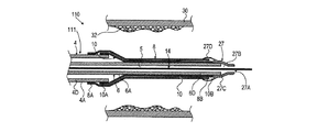
さらに、本発明のカテーテルの一実施形態によれば、カテーテルはオーバー・ザ・ワイヤ型(OVT)カテーテルであり、カテーテルシャフトは、遠位端部、近位端部及びルーメンを有する中空の外側導管を含む。カテーテルシャフトは、ガイドワイヤの通過に適した中空の内側導管をさらに含む。内側導管は、遠位部分、近位部分及びルーメンを有している。内側導管は、外側導管のルーメン内に配置されており、かつ体内でのカテーテルの操作中は常に内側導管の遠位部分の遠位端部が外側導管の遠位端部を越えて延出するように配置されている。バルーンの近位端部は外側導管の遠位端部に密封的に結合されており、バルーンの遠位端部は内側導管の遠位端部に密封的に結合されている。スリーブの近位端部は、カテーテルシャフトの外側導管の遠位端部に密封的に結合されている。カテーテルは、膨張可能バルーンへの膨張流体の流入排出のための、外側導管のルーメンに流体連通する流体ポートと、カテーテルの遠位端部に配置されたガイドワイヤポートとを含む。ガイドワイヤポートは、内側導管のルーメン内にガイドを挿入するのに適した開口部を有する。 Further, according to one embodiment of the catheter of the present invention, the catheter is an over-the-wire (OVT) catheter and the catheter shaft is a hollow outer conduit having a distal end, a proximal end and a lumen. including. The catheter shaft further includes a hollow inner conduit suitable for passage of the guide wire. The inner conduit has a distal portion, a proximal portion and a lumen. The inner conduit is disposed within the lumen of the outer conduit and the distal end of the distal portion of the inner conduit extends beyond the distal end of the outer conduit whenever the catheter is manipulated in the body. Are arranged as follows. The proximal end of the balloon is sealingly coupled to the distal end of the outer conduit, and the distal end of the balloon is sealingly coupled to the distal end of the inner conduit. The proximal end of the sleeve is sealingly coupled to the distal end of the outer conduit of the catheter shaft. The catheter includes a fluid port in fluid communication with the lumen of the outer conduit for inflow and outflow of inflation fluid into the inflatable balloon, and a guide wire port located at the distal end of the catheter. The guidewire port has an opening suitable for inserting the guide into the lumen of the inner conduit.
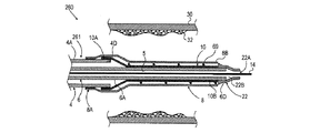
さらに、本発明のカテーテルの一実施形態によれば、カテーテルは迅速交換型カテーテルであり、カテーテルシャフトは、遠位端部、近位端部及びルーメンを有する中空の外側導管を含む。カテーテルシャフトは、ガイドワイヤの通過に適した中空の内側導管をさらに含む。内側導管は、角度付けされた近位部分を有しており、角度付けされた近位部分は、外側導管の壁部に固定して結合されており、かつガイドワイヤを挿入するための開口部を外側導管に形成するように外側導管の壁部を密封的に貫通している。内側導管は、遠位部分及びルーメンをさらに有している。内側導管は、外側導管のルーメン内に配置されており、かつ内側導管の遠位部分の遠位端部が外側導管の遠位端部を越えて延出するように配置されている。膨張可能バルーンは、近位端部及び遠位端部を有している。バルーンの近位端部は外側導管の遠位端部に密封的に結合されており、バルーンの遠位端部は内側導管の遠位端部に密封的に結合されている。スリーブの近位端部は、外側導管の遠位端部に密封的に結合されている。カテーテルは、膨張可能バルーンへの膨張流体の流入排出のための、外側導管のルーメンに流体連通する流体ポートを含む。 Furthermore, according to one embodiment of the catheter of the present invention, the catheter is a rapid exchange catheter and the catheter shaft includes a hollow outer conduit having a distal end, a proximal end and a lumen. The catheter shaft further includes a hollow inner conduit suitable for passage of the guide wire. The inner conduit has an angled proximal portion, the angled proximal portion is fixedly coupled to the wall of the outer conduit and an opening for inserting a guide wire Are sealed through the wall of the outer conduit so as to form an outer conduit. The inner conduit further has a distal portion and a lumen. The inner conduit is disposed within the lumen of the outer conduit and is disposed such that the distal end of the distal portion of the inner conduit extends beyond the distal end of the outer conduit. The inflatable balloon has a proximal end and a distal end. The proximal end of the balloon is sealingly coupled to the distal end of the outer conduit, and the distal end of the balloon is sealingly coupled to the distal end of the inner conduit. The proximal end of the sleeve is sealingly coupled to the distal end of the outer conduit. The catheter includes a fluid port in fluid communication with the lumen of the outer conduit for inflow and outflow of inflation fluid into the inflatable balloon.
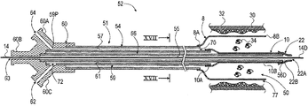
さらに、本発明のカテーテルの一実施形態によれば、カテーテルシャフトは、内部に少なくとも3つの互いから流体的に分離された中空通路を含む。当該中空通路は、ガイドワイヤを挿入するための第1の中空通路と、バルーン内に膨張流体を流入させるため及びバルーンから膨張流体を排出させるための第2の中空通路と、バルーンとスリーブとの間のキャビティに流体連通させた第3の中空通路とを含む。キャビティ内または第3の中空通路内におけるデブリの捕捉及び保持を助けるために、外部吸引源からの吸引力を第3の中空通路を介してキャビティに加えることができる。 Further, according to one embodiment of the catheter of the present invention, the catheter shaft includes at least three hollow passages fluidly separated from one another therein. The hollow passage includes a first hollow passage for inserting a guide wire, a second hollow passage for allowing inflation fluid to flow into and out of the balloon, a balloon and a sleeve. And a third hollow passage in fluid communication with the cavity therebetween. A suction force from an external suction source can be applied to the cavity via the third hollow passage to help capture and retain debris within the cavity or the third hollow passage.
さらに、本発明のカテーテルの一実施形態によれば、カテーテルシャフトは、第1の導管、第2の導管及び第3の導管を含む。第3の導管の遠位端部が第2の導管の遠位端部を越えて遠位方向に延出するように、第1の導管が第2の導管内に配置されている。第1の中空通路は、第1の導管のルーメンである。第2の導管の外面と第3の導管の内面との間に画定された環状空間が第3の中空通路であるように、第2の導管が第3の導管のルーメン内に配置されている。スリーブの近位端部は、第3の導管に密封的に結合されている。バルーンの近位端部は、第2の導管の遠位端部に密封的に結合されている。バルーンの遠位端部は、第2の導管の遠位端部を越えて突出する第1の導管の遠位端部に密封的に結合されている。 Furthermore, according to one embodiment of the catheter of the present invention, the catheter shaft includes a first conduit, a second conduit, and a third conduit. The first conduit is disposed within the second conduit such that the distal end of the third conduit extends distally beyond the distal end of the second conduit. The first hollow passage is the lumen of the first conduit. The second conduit is disposed within the lumen of the third conduit such that the annular space defined between the outer surface of the second conduit and the inner surface of the third conduit is the third hollow passage. . The proximal end of the sleeve is sealingly coupled to the third conduit. The proximal end of the balloon is sealingly coupled to the distal end of the second conduit. The distal end of the balloon is sealingly coupled to the distal end of the first conduit that projects beyond the distal end of the second conduit.
さらに、本発明のカテーテルの一実施形態によれば、カテーテルの近位端部は、第3の通路に吸引力を加えるため及びコントラスト増強流体を体腔へ注入するための第3の通路に流体連通する流体ポートを含む。カテーテルの近位端部はまた、バルーンを膨張及び収縮させるための第2の通路に流体連通する膨張ポートと、第1の中空通路内へガイドワイヤを挿入するためのガイドワイヤポートとを含む。 Further, according to one embodiment of the catheter of the present invention, the proximal end of the catheter is in fluid communication with the third passage for applying suction to the third passage and for injecting contrast enhancing fluid into the body cavity. Including fluid ports. The proximal end of the catheter also includes an inflation port in fluid communication with the second passage for inflating and deflating the balloon, and a guide wire port for inserting a guide wire into the first hollow passage.
さらに、本発明のカテーテルの一実施形態によれば、カテーテルシャフトは、内側導管、中間導管及び外側導管を含む。内側導管は中間導管内に配置されており、中間導管は、内側導管の遠位端部が中間導管の遠位端部を越えて遠位方向に延出するように外側導管内に配置されている。内側導管は、中間導管の遠位端部を越えて遠位方向に突出する真っ直ぐな遠位部分と、中間導管の壁部を密封的に貫通しかつ、ガイドワイヤを挿入するための開口部を外側導管に形成するために外側導管の壁部をも密封的に貫通している角度付けされた(曲がった)近位部分とを有している。第1の中空通路は、内側導管のルーメンである。第2の中空通路は、内側導管と中間導管との間の空間である。中間導管と外側導管との間において画定される空間が第3の中空通路であるように、中間導管は外側導管のルーメン内に配置されている。スリーブの近位端部は、外側導管の遠位端部に密封的に結合されている。バルーンの近位端部は、中間導管の遠位端部に密封的に結合されており、バルーンの遠位端部は、中間導管の遠位端部を越えて突出する内側導管の遠位端部に密封的に結合されている。 Furthermore, according to one embodiment of the catheter of the present invention, the catheter shaft includes an inner conduit, an intermediate conduit and an outer conduit. The inner conduit is disposed within the intermediate conduit, and the intermediate conduit is disposed within the outer conduit such that the distal end of the inner conduit extends distally beyond the distal end of the intermediate conduit. Yes. The inner conduit has a straight distal portion that projects distally beyond the distal end of the intermediate conduit, an opening for sealingly penetrating the wall of the intermediate conduit and inserting a guide wire. And an angled (bent) proximal portion that also sealingly penetrates the wall of the outer conduit to form the outer conduit. The first hollow passage is the lumen of the inner conduit. The second hollow passage is the space between the inner conduit and the intermediate conduit. The intermediate conduit is disposed within the lumen of the outer conduit such that the space defined between the intermediate conduit and the outer conduit is the third hollow passage. The proximal end of the sleeve is sealingly coupled to the distal end of the outer conduit. The proximal end of the balloon is sealingly coupled to the distal end of the intermediate conduit, and the distal end of the balloon is the distal end of the inner conduit that projects beyond the distal end of the intermediate conduit. The part is hermetically coupled.
さらに、本発明のカテーテルの一実施形態によれば、カテーテルの近位端部は、第3の通路に吸引力を加えるため及びコントラスト増強流体を体腔へ注入するための第3の通路に流体連通する流体ポートを含む。カテーテルの近位端部はまた、バルーンを膨張及び収縮させるための第2の通路に流体連通する膨張ポートを含む。外側導管の壁部に形成され、内側導管のルーメンにアクセスする開口部は、外側導管の壁部の近位端部と遠位端部との間に配置されている。 Further, according to one embodiment of the catheter of the present invention, the proximal end of the catheter is in fluid communication with the third passage for applying suction to the third passage and for injecting contrast enhancing fluid into the body cavity. Including fluid ports. The proximal end of the catheter also includes an inflation port in fluid communication with the second passage for inflating and deflating the balloon. An opening formed in the wall of the outer conduit and accessing the lumen of the inner conduit is disposed between the proximal and distal ends of the outer conduit wall.
さらに、本発明のカテーテルの一実施形態によれば、スリーブは、バルーンが収縮状態にあるときにバルーンの遠位端部を越えて遠位方向に延出する遠位端部を有するスリーブ、バルーンが収縮状態にあるときにバルーンの遠位端部と同じ長手方向位置へ遠位方向に延出する遠位端部を有するスリーブ及び、バルーンが収縮状態にあるときにバルーンの遠位端部がスリーブの遠位端部を越えて遠位方向に延出するように遠位端部を有するスリーブからなる群から選択される。 Furthermore, according to one embodiment of the catheter of the present invention, the sleeve has a distal end that extends distally beyond the distal end of the balloon when the balloon is in a deflated state, the balloon A sleeve having a distal end extending distally to the same longitudinal position as the distal end of the balloon when the balloon is in a deflated state, and a distal end of the balloon when the balloon is in a deflated state Selected from the group consisting of a sleeve having a distal end to extend distally beyond the distal end of the sleeve.
さらに、本発明のカテーテルの一実施形態によれば、スリーブは、バルーンが収縮状態にあるときにバルーンの遠位端部を越えて遠位方向に延出する遠位端部を有するスリーブ、バルーンが収縮状態にあるときにバルーンの遠位端部と同じ長手方向位置へ遠位方向に延出する遠位端部を有するスリーブ及び、バルーンが収縮状態にあるときにバルーンの遠位端部がスリーブの遠位端部を越えて遠位方向に延出するように遠位端部を有するスリーブからなる群から選択される。 Furthermore, according to one embodiment of the catheter of the present invention, the sleeve has a distal end that extends distally beyond the distal end of the balloon when the balloon is in a deflated state, the balloon A sleeve having a distal end extending distally to the same longitudinal position as the distal end of the balloon when the balloon is in a deflated state, and a distal end of the balloon when the balloon is in a deflated state Selected from the group consisting of a sleeve having a distal end to extend distally beyond the distal end of the sleeve.
さらに、本発明のカテーテルの一実施形態によれば、カテーテルは、バルーンを収縮させた後にスリーブを拡張状態において支持するために、バルーンとスリーブとの間に配置されたスリーブ支持部材をさらに含む。 Furthermore, according to one embodiment of the catheter of the present invention, the catheter further includes a sleeve support member disposed between the balloon and the sleeve to support the sleeve in the expanded state after the balloon is deflated.
さらに、本発明のカテーテルの一実施形態によれば、スリーブ支持部材は、スリーブが拡張状態にあるときにスリーブの遠位端部と同じ距離まで延びている遠位端部を有するスリーブ支持部材と、スリーブが拡張状態にあるときにスリーブの遠位端部がスリーブ支持部材の遠位端部を越えて遠位方向に延出するように遠位端部を有するスリーブ支持部材と、スリーブが拡張状態にあるときにスリーブ支持部材の遠位端部がスリーブの遠位端部を越えて遠位方向に延出するように遠位端部を有するスリーブ支持部材とから選択される。 Furthermore, according to one embodiment of the catheter of the present invention, the sleeve support member has a distal end that extends to the same distance as the distal end of the sleeve when the sleeve is in the expanded state; A sleeve support member having a distal end so that the distal end of the sleeve extends distally beyond the distal end of the sleeve support member when the sleeve is in an expanded state; A sleeve support member having a distal end so that the distal end of the sleeve support member extends distally beyond the distal end of the sleeve when in a state.
さらに、本発明のカテーテルの一実施形態によれば、スリーブ支持部材は、拡張可能な弾性部材、圧縮された弾性部材、拡張可能なバネ様部材、圧縮されたバネ様部材、コイル部材、圧縮された弾性コイル部材またはらせん状コイル部材から選択される。 Furthermore, according to one embodiment of the catheter of the present invention, the sleeve support member is an expandable elastic member, a compressed elastic member, an expandable spring-like member, a compressed spring-like member, a coil member, a compressed member. Selected from an elastic coil member or a helical coil member.
さらに、本発明のカテーテルの一実施形態によれば、スリーブは、穿孔を有する有孔スリーブであり、カテーテルは、スリーブとバルーンとの間に配置された物質をさらに含み、それによって、バルーンの膨張時に物質の少なくとも一部が穿孔から押し出されて、カテーテルが配置されている体腔壁に適用されるようになっている。 Furthermore, according to one embodiment of the catheter of the present invention, the sleeve is a perforated sleeve having perforations, and the catheter further comprises a material disposed between the sleeve and the balloon, thereby expanding the balloon. Sometimes at least a portion of the material is pushed out of the perforation and applied to the body cavity wall where the catheter is located.
さらに、本発明のカテーテルの一実施形態によれば、穿孔は、0.001〜0.5mmの範囲の開口寸法を有している。 Furthermore, according to one embodiment of the catheter of the present invention, the perforation has an opening dimension in the range of 0.001 to 0.5 mm.
さらに、本発明のカテーテルの一実施形態によれば、穿孔は、円形断面を有する穿孔または非円形断面を有する穿孔から選択される。 Further, according to one embodiment of the catheter of the present invention, the perforations are selected from perforations having a circular cross section or perforations having a non-circular cross section.
さらに、本発明のカテーテルの一実施形態によれば、物質は、治療用物質、診断用物質、薬剤、治療用組成物、医薬物、診断用組成物、生理学的活性薬剤、生化学的活性薬剤、1若しくは複数の生細胞、DNA、RNA、核酸、治療部位の細胞に遺伝物質を送達するためのベクター、抗炎症薬、抗再狭窄剤、細胞増殖抑制剤、平滑筋増殖抑制剤、パクリタキセル、ラパマイシン、エベロリムス、血管作用薬、血管拡張薬、血管収縮薬、抗生物質、抗凝固薬、血小板凝集阻害薬、線維化抑制薬、薬学的に許容される賦形剤、油脂ベースの賦形剤、またはそれらの任意の組合せから選択された1若しくは複数の材料を含む。 Furthermore, according to one embodiment of the catheter of the present invention, the substance is a therapeutic substance, a diagnostic substance, a drug, a therapeutic composition, a pharmaceutical product, a diagnostic composition, a physiologically active drug, a biochemically active drug. One or more living cells, DNA, RNA, nucleic acids, vectors for delivering genetic material to cells at the treatment site, anti-inflammatory agents, anti-restenosis agents, cell growth inhibitors, smooth muscle growth inhibitors, paclitaxel, Rapamycin, everolimus, vasoactive drugs, vasodilators, vasoconstrictors, antibiotics, anticoagulants, platelet aggregation inhibitors, fibrosis inhibitors, pharmaceutically acceptable excipients, fat based excipients, Or one or more materials selected from any combination thereof.
さらに、本発明のカテーテルの一実施形態によれば、有孔スリーブは、バルーンの膨張時に物質をスリーブの外面に押し出すことを可能にする開放キャビティを有するスポンジ様構造を有する材料を含む。 Further, according to one embodiment of the catheter of the present invention, the perforated sleeve comprises a material having a sponge-like structure with an open cavity that allows the substance to be pushed onto the outer surface of the sleeve upon inflation of the balloon.
さらに、本発明のカテーテルの一実施形態によれば、カテーテルは、その遠位端部において、カテーテルシャフトに取り付けられた柔軟性先端部をさらに含む。 Furthermore, according to one embodiment of the catheter of the present invention, the catheter further comprises a flexible tip attached at its distal end to the catheter shaft.
さらに、本発明のカテーテルの一実施形態によれば、柔軟性先端部は、カテーテルを体腔に挿入している間及びカテーテルの遠位端部を体腔内の治療部位に向けて進めている間にバルーンの遠位端部及びスリーブの遠位端部のうちの1つ以上を固定するための保持部材を含む。 Further, according to one embodiment of the catheter of the present invention, the flexible tip is inserted during insertion of the catheter into the body cavity and while the distal end of the catheter is advanced toward the treatment site within the body cavity. A retaining member for securing one or more of the distal end of the balloon and the distal end of the sleeve is included.
さらに、本発明のカテーテルの一実施形態によれば、バルーンを膨張させる前にスリーブは円形断面を有し、バルーンを膨張させる前にバルーンはカテーテルシャフトの一部の周囲に折り畳まれている。 Further, according to one embodiment of the catheter of the present invention, the sleeve has a circular cross section before inflating the balloon, and the balloon is folded around a portion of the catheter shaft before inflating the balloon.
さらに、本発明のカテーテルの一実施形態によれば、カテーテルのクロッシングプロファイルを低減させるために、バルーンを膨張させる前にスリーブ及びバルーンの両方がカテーテルシャフトの一部の周囲に折り畳まれている。 Further, according to one embodiment of the catheter of the present invention, both the sleeve and the balloon are folded around a portion of the catheter shaft prior to inflating the balloon to reduce the crossing profile of the catheter.
さらに、本発明のカテーテルの一実施形態によれば、カテーテルのクロッシングプロファイルを低減させるために、バルーンを膨張させる前にバルーンはカテーテルシャフトの一部の周囲に折り畳まれており、スリーブはバルーン上に折り畳まれている。 Further, according to one embodiment of the catheter of the present invention, to reduce the crossing profile of the catheter, the balloon is folded around a portion of the catheter shaft before the balloon is inflated and the sleeve is over the balloon. It is folded.
さらに、本発明のカテーテルの一実施形態によれば、スリーブは、コンプライアント材料、セミコンプライアント材料、ノンコンプライアント材料、伸張可能な材料、伸張可能でない材料、アニール処理された伸張可能な材料、二軸配向工程によって分子配向された伸張可能でない延伸材料、またはそれらの任意の組合せから選択された材料を含む。 Further, according to one embodiment of the catheter of the present invention, the sleeve is made of compliant material, semi-compliant material, non-compliant material, stretchable material, non-stretchable material, annealed stretchable material, It includes materials selected from non-extensible stretchable materials that are molecularly oriented by an axial orientation process, or any combination thereof.
さらに、本発明のカテーテルの一実施形態によれば、スリーブは、ポリマー系材料、ナイロン(登録商標)ナイロン12(登録商標)、PET、ポリアミドPA12、グリルアミド(登録商標)L25、グリルアミド(登録商標)L55、PA11、ポリエーテルブロックアミド(ペバックス(PEBAX)(登録商標)7233、ペバックス(登録商標)7033、ペバックス(登録商標)6333)、グリルフレックス(Grilflex)(登録商標)ELG6260、ポリエステル、ポリエチレン、ポリウレタン、及びそれらの任意の組合せから選択された材料を含む。 Furthermore, according to one embodiment of the catheter of the present invention, the sleeve is made of a polymer-based material, nylon (registered trademark) nylon 12 (registered trademark), PET, polyamide PA12, grillamide (registered trademark) L25, grillamide (registered trademark). L55, PA11, polyether block amide (PEBAX (registered trademark) 7233, Pebax (registered trademark) 7033, Pebax (registered trademark) 6333), Grillflex (registered trademark) ELG6260, polyester, polyethylene, polyurethane And materials selected from any combination thereof.
さらに、本発明のカテーテルの一実施形態によれば、カテーテルは、カテーテルシャフトに取り付けられた1若しくは複数のX線不透過性マーカと、カテーテルの1若しくは複数の部分に取り付けられた、3次元カテーテル位置決めシステムが3次元空間に画定された座標系におけるカテーテルの少なくとも一部の位置を決定することを可能ならしめるための1若しくは複数の位置検出支援装置とからなる群から選択される1若しくは複数の装置をさらに含む。 In addition, according to one embodiment of the catheter of the present invention, the catheter comprises one or more radiopaque markers attached to the catheter shaft and a three-dimensional catheter attached to one or more portions of the catheter. One or more selected from the group consisting of one or more position detection assisting devices for enabling the positioning system to determine the position of at least a portion of the catheter in a coordinate system defined in a three-dimensional space. The apparatus further includes a device.
さらに、本発明のカテーテルの一実施形態によれば、バルーンは、円錐状またはテーパ状の端部を有する円筒状バルーン、2つ以上の円筒状部分を有しかつ該円筒状部分のうちの少なくともいくつかの径が異なる段付きバルーン、円錐状または円錐台状の長手方向断面形状を有するバルーン、テーパ状の長手方向断面形状を有するバルーン、非線形に変化する長手方向断面形状を有するバルーン、少なくとも1つの波状部分を有するバルーン、均一な壁厚を有するバルーン及び不均一な壁厚を有するバルーンからなる群から選択されたものである。 Furthermore, according to one embodiment of the catheter of the present invention, the balloon has a cylindrical balloon with a conical or tapered end, has two or more cylindrical portions and at least one of the cylindrical portions. Several stepped balloons of different diameters, balloons having a conical or frusto-conical longitudinal cross-sectional shape, balloons having a tapered longitudinal cross-sectional shape, balloons having a non-linearly varying longitudinal cross-sectional shape, at least one Selected from the group consisting of a balloon having two wavy portions, a balloon having a uniform wall thickness and a balloon having a non-uniform wall thickness.
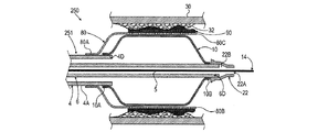
本発明の方法の一実施形態によれば、体腔を治療する方法も提供される。本方法は、カテーテルを体腔へ挿入するステップと、体腔の治療部位にスリーブを配置するステップと、バルーンを膨張させることによってスリーブを拡張状態まで拡張させるステップと、バルーンを収縮させることによって拡張させたスリーブとバルーンとの間に開放キャビティを形成し、この収縮により、キャビティ内にデブリ及び/または粒子状物質を捕捉して保持する吸引力を発生させるステップとを含む。 According to one embodiment of the method of the present invention, a method of treating a body cavity is also provided. The method includes inserting a catheter into a body cavity, placing a sleeve at a treatment site in the body cavity, expanding the sleeve to an expanded state by inflating the balloon, and expanding by deflating the balloon. Forming an open cavity between the sleeve and the balloon, the contraction generating a suction force that captures and retains debris and / or particulate matter within the cavity.
さらに、本発明の方法の一実施形態によれば、カテーテルを挿入するステップが、カテーテルシャフト内に形成された中空通路に通されたガイドワイヤに沿わせてカテーテルを体腔へ挿入するステップを含む。 Further, according to one embodiment of the method of the present invention, the step of inserting the catheter includes the step of inserting the catheter into a body cavity along a guide wire threaded through a hollow passage formed in the catheter shaft.
さらに、本発明の方法の一実施形態によれば、体腔は血管である。 Furthermore, according to one embodiment of the method of the present invention, the body cavity is a blood vessel.
さらに、本発明の方法の一実施形態によれば、バルーンを膨張させるステップはさらに、血管内の閉塞部を開大する。 Furthermore, in accordance with one embodiment of the method of the present invention, the step of inflating the balloon further opens the occlusion in the blood vessel.
さらに、本発明の方法の一実施形態によれば、カテーテルは、バルーンとスリーブとの間に配置されたスリーブ支持部材をさらに含む。バルーンを膨張させるステップは、スリーブの拡張状態を支えるためにバルーンによってスリーブ支持部材を拡張状態まで拡張させるステップ、または、スリーブの拡張状態を支えるためにスリーブ支持部材を初期圧縮状態から拡張状態まで拡張させるステップから選択されるステップをさらに含む。 Furthermore, according to one embodiment of the method of the present invention, the catheter further comprises a sleeve support member disposed between the balloon and the sleeve. The step of inflating the balloon includes expanding the sleeve support member to the expanded state by the balloon to support the expanded state of the sleeve, or expanding the sleeve support member from the initial compressed state to the expanded state to support the expanded state of the sleeve. The method further includes a step selected from the steps to be performed.
さらに、本発明の方法の一実施形態によれば、スリーブは有孔スリーブであり、カテーテルは、バルーンと有孔スリーブとの間に配置された物質をさらに含む。バルーンを膨張させるステップは、有孔スリーブの穿孔から物質を押し出して物質の一部を体腔の一部に適用することによって体腔内の所定部位に物質を適用するステップをさらに含む。 Furthermore, according to one embodiment of the method of the present invention, the sleeve is a perforated sleeve and the catheter further comprises a substance disposed between the balloon and the perforated sleeve. Inflating the balloon further includes applying the substance to a predetermined site within the body cavity by extruding the substance from the perforation of the perforated sleeve and applying a portion of the substance to the part of the body cavity.
さらに、本発明の方法の一実施形態によれば、カテーテルは、スリーブの外面上に配置されたステントをさらに含み、バルーンを膨張させるステップは、ステントを拡張させることにより治療体腔内でステントを展開するステップをさらに含む。 Further, according to one embodiment of the method of the present invention, the catheter further comprises a stent disposed on the outer surface of the sleeve, and the step of inflating the balloon deploys the stent within the treatment body cavity by expanding the stent. The method further includes the step of:
さらに、本発明の方法の一実施形態によれば、カテーテルシャフトは、バルーンとスリーブとの間に形成されたキャビティに流体連通する中空通路を含み、本方法は、カテーテルのキャビティ内におけるデブリの捕捉及び保持を助けるために、外部吸引源から中空通路を通してキャビティへ吸引力を加えるステップをさらに含む。 Furthermore, according to one embodiment of the method of the present invention, the catheter shaft includes a hollow passage in fluid communication with a cavity formed between the balloon and the sleeve, the method comprising capturing debris within the catheter cavity. And further applying a suction force from an external suction source through the hollow passage to the cavity to assist in retention.
さらに、本発明の方法の一実施形態によれば、吸引力を加えるステップは、キャビティに流体連通させた中空通路内においてデブリの少なくとも一部を捕捉して保持するステップをさらに含む。 Further, according to one embodiment of the method of the present invention, applying the suction force further includes capturing and retaining at least a portion of the debris in a hollow passage in fluid communication with the cavity.
さらに、本発明の方法の一実施形態によれば、カテーテルシャフトは、内部に少なくとも3つの互いから流体的に分離された中空通路を含む。第1の中空通路は、ガイドワイヤを挿入するための、カテーテルシャフトに設けられた第1の開口部と、ガイドワイヤを出せるようにするための、カテーテルシャフトの遠位端部に設けられた第2の開口部とを有する。カテーテルシャフトは、バルーンに膨張流体を流入させるため及びバルーンから膨張流体を排出させるための第2の中空通路と、バルーンとスリーブとの間に形成されたキャビティに流体連通させた第3の中空通路とを含む。本方法は、キャビティ内または第3の中空通路内におけるデブリの捕捉及び保持を助けるために、外部吸引源から第3の中空通路を通してキャビティへ吸引力を加えるステップをさらに含む。 Further, according to one embodiment of the method of the present invention, the catheter shaft includes at least three hollow passages fluidly separated from one another therein. The first hollow passage has a first opening provided in the catheter shaft for inserting the guide wire, and a first opening provided in the distal end portion of the catheter shaft for allowing the guide wire to exit. 2 openings. The catheter shaft has a second hollow passage for inflating fluid into and out of the balloon, and a third hollow passage in fluid communication with a cavity formed between the balloon and the sleeve. Including. The method further includes applying a suction force from the external suction source to the cavity through the third hollow passage to help capture and retain debris within the cavity or the third hollow passage.
さらに、本発明の方法の一実施形態によれば、本方法は、体腔内で診断手技を行うための診断機器または体腔内で治療手技を行うための治療機器から選択された医療機器を、シャフトの中空通路を通して挿入するステップをさらに含む。 Furthermore, according to one embodiment of the method of the present invention, the method comprises: a shaft selected from a diagnostic device for performing a diagnostic procedure in a body cavity or a therapeutic device for performing a treatment procedure in a body cavity; And inserting through the hollow passage.
さらに、本発明の方法の一実施形態によれば、上記医療機器は、ガイドワイヤをカテーテル内に挿入するために用いられる中空通路を通してカテーテル内に挿入され、本方法は、医療機器を挿入する前に中空通路からガイドワイヤを引き抜くステップをさらに含む。 Furthermore, according to one embodiment of the method of the present invention, the medical device is inserted into the catheter through a hollow passage used to insert a guide wire into the catheter, the method prior to inserting the medical device. And a step of withdrawing the guide wire from the hollow passageway.
さらに、本発明の方法の一実施形態によれば、本方法は、カテーテルシャフトの中空通路を通してコントラスト増強剤を注入するステップをさらに含む。 Furthermore, according to one embodiment of the method of the present invention, the method further comprises injecting a contrast enhancing agent through the hollow passage of the catheter shaft.
最後に、本発明の方法の一実施形態によれば、バルーンを膨張させるステップは、バルーンによってスリーブを広げるステップ、バルーンによってスリーブを展開するステップ、バルーンによってスリーブを拡張させるステップ、バルーンによってスリーブを伸張させるステップ、またはそれらの任意の組合せから選択されるステップを含む。 Finally, according to one embodiment of the method of the present invention, the step of inflating the balloon includes expanding the sleeve with the balloon, deploying the sleeve with the balloon, expanding the sleeve with the balloon, and stretching the sleeve with the balloon. Or a step selected from any combination thereof.
本明細書において、本発明は、添付の図面を参照してほんの一例として説明されているが、図面において、同様の構成要素には同様の符号を付してある。 In the present description, the invention is described by way of example only with reference to the accompanying drawings, in which like components are labeled with like reference numerals.
以下、本発明の装置の一例を、添付図面を参照して説明する。図面を参照して詳細に示される事項は、例示を目的として、本発明の好適な実施形態の例示的な説明を目的とするものに過ぎず、本発明の原理及び概念上の態様についての最も有用かつ容易に理解される説明であると考えられるものを提供するという理由で提示されていることを強調したい。これに関し、本発明の基本的な理解に必要である以上に詳細に本発明の構造上の詳細を示すことを試みるのではなく、図面を用いて行われた説明によれば、本発明のいくつかの形態がいかに実際に具体化され得るかということが、当業者には明白である。 Hereinafter, an example of the apparatus of the present invention will be described with reference to the accompanying drawings. The matter set forth in detail with reference to the drawings is for purposes of illustration only and is for purposes of illustration only of the preferred embodiment of the invention, and is best described with respect to principles and conceptual aspects of the invention. I would like to emphasize that it is presented because it provides what is considered to be a useful and easily understood explanation. In this regard, rather than attempt to show structural details of the present invention in more detail than is necessary for a basic understanding of the present invention, according to the description made with reference to the drawings, It will be clear to those skilled in the art how such a form may actually be embodied.
簡略化のために、様々な特徴のいくつかの明確な組み合わせは、明示的に図示及び/または説明していない。本明細書中に開示される方法または装置の特徴の任意の組み合わせは、任意の態様(特徴の任意の組み合わせを含む)で組み合わせることが可能であり、特徴の任意の組み合わせは、任意の実施形態に含めること及び/または任意の実施形態から除くことができる。 For the sake of brevity, some distinct combinations of various features are not explicitly shown and / or described. Any combination of the features of the methods or apparatus disclosed herein may be combined in any manner (including any combination of features), and any combination of features may be implemented in any embodiment And / or excluded from any embodiment.
便宜上、本明細書に関連して、いくつかの用語をここに提示する。本明細書中に明示的または黙示的に定義されている限り、これらの定義は、当分野の当業者により定義された用語の使用と矛盾することなく理解されるものとする。さらに、これらの定義は、その使用と矛盾することのない最も幅広い意味に解釈されるものとする。 For convenience, a number of terms are presented here in connection with the present specification. To the extent that they are explicitly or implicitly defined herein, these definitions are to be understood consistent with the use of terms defined by those skilled in the art. Furthermore, these definitions shall be construed in the broadest sense consistent with their use.
いくつかの実施形態は、対象物または導管の「径」、例えば、外側導管のルーメンの「径」(例えば、図10の外側導管204のルーメン220の径)に関する。円形断面を有する導管の場合は、用語「径」は、円形ルーメンの直径を意味することに留意されたい。一方、非円形断面を有するルーメンまたは導管の場合は、「径」は、ルーメンまたは導管の断面積の平方根と定義される。
Some embodiments relate to the “diameter” of the object or conduit, eg, the “diameter” of the lumen of the outer conduit (eg, the diameter of the
本願の明細書及び特許請求の範囲では、「含む(comprise)」、「含む(include)」、「有する(have)」の各動詞またはその同根語は、その動詞の目的語が、その動詞の主語の数、構成要素、要素、または部品を完全に列挙する必要がないことを示すのに使用される。 In the specification and claims of this application, the verbs “comprise”, “include”, “have”, or their roots, the object of the verb is the verb Used to indicate that the number of subjects, components, elements, or parts need not be fully enumerated.
引用された全ての文献は、その全体が、本明細書に参考として組み込まれる。本明細書における参照文献の引用は、それらの参照文献が先行技術であることを承認するものではない。 All references cited are incorporated herein by reference in their entirety. Citation of references herein is not an admission that such references are prior art.
本明細書では、冠詞「ある(a、an)」は、その冠詞の文法上の目的語が、1つまたは1より多い(すなわち、少なくとも1つである)ことを意味する。例えば、「ある要素」は、1つの要素または1より多くの要素を意味する。 As used herein, the article “a, an” means that the article has one or more grammatical objects (ie, at least one). For example, “an element” means one element or more than one element.
本明細書では、用語「含む(including)」は、「限定されないが、〜を含む(including but not limited to)」の意味を含み、相互互換的に使用される。用語「または(or)」は、文脈上明確に別途示されない限り、用語「及び/または(and/or)」の意味を含み、相互互換的に使用される。用語「例えば(such as)」は、「例えば〜だがこれに限らない(such as but not limited to)」の意味を含み、相互互換的に使用される。 As used herein, the term “including” includes the meaning of “including but not limited to” and is used interchangeably. The term “or” includes the meaning of the term “and / or” and is used interchangeably, unless the context clearly indicates otherwise. The term “such as” includes the meaning of “such as but not limited to” and is used interchangeably.
本発明の装置をその実施形態の詳細を用いて説明するが、それらは、一例として挙げられ、本発明の範囲の限定を意図するものではない。説明される実施形態は、様々な要素を含むが、それらの全ては、本発明の全ての実施形態で必須ではない。本発明のいくつかの実施形態は、要素または複数の要素の可能な組み合わせのいくつかのみを使用する。当業者であれば、説明された本発明の実施形態の変形例、及び説明された実施形態に示された要素の他の組み合わせを含む本発明の実施形態を想到可能であろう。 The apparatus of the present invention will be described using details of its embodiments, which are given by way of example and are not intended to limit the scope of the present invention. The described embodiments include various elements, all of which are not required in all embodiments of the invention. Some embodiments of the invention use only some of the elements or possible combinations of elements. Those skilled in the art will be able to contemplate embodiments of the present invention that include variations of the described embodiments of the invention and other combinations of the elements shown in the described embodiments.
本願の明細書及び特許請求の範囲においては、用語「遠位」及び「近位」は、次のように定義される。カテーテルの最初に体内に挿入される側(先端側)または端部を遠位側または遠位端部と呼び、カテーテルの他方の側(後端側)または端部を近位側または近位端部と呼ぶ。例えば、図1のバルーンカテーテル2では、カテーテル2の近位端部にコネクタ部材12が結合しており、バルーン10はカテーテル2の遠位側に配置されている。
In the specification and claims of this application, the terms “distal” and “proximal” are defined as follows. The side (tip side) or end of the catheter that is first inserted into the body is called the distal side or distal end, and the other side (rear side) or end of the catheter is the proximal side or proximal end. Called the part. For example, in the balloon catheter 2 of FIG. 1, the
また、本願の明細書及び特許請求の範囲においては、用語「導管」及び「チューブ」は、円形断面または非円形断面を有する細長い中空部材を定義するのに相互互換的に使用される。本願で開示及び図示される導管は、好ましいことに円形断面積を有しているが、このことは本発明の実施に必須ではない。すなわち、用語「導管」及び「チューブ」は、非円形断面を有する細長い中空部材、これに限定されないが、楕円形断面、多角形断面、不規則形断面を有する細長い中空部材を含む。 Also, in the present specification and claims, the terms “conduit” and “tube” are used interchangeably to define an elongated hollow member having a circular or non-circular cross section. Although the conduits disclosed and illustrated herein preferably have a circular cross-sectional area, this is not essential to the practice of the invention. That is, the terms “conduit” and “tube” include an elongated hollow member having a non-circular cross section, including but not limited to an elliptical cross section, a polygonal cross section, an irregular cross section.
同様に、本願では、用語「環状空間」は、2つの中空導管、例えば、外側導管(第2の導管)と、外側導管よりも小さな径を有し外側導管のルーメン内に配置される内側導管(第1の導管)とによって画成される空間を説明するために使用される。用語「環状空間」は、外側導管(第2の導管)のルーメンの内面と、内側導管(第1の導管)の外面との間の空間と定義される。本願は、円形断面を有する導管または非円形断面(これに限定されないが、例えば、楕円形断面、不規則形断面、多角形断面)を有する導管の使用を意図及び開示しているので、内側導管及び外側導管の上記断面の全ての可能な組み合わせ及び置き換えが、本願のカテーテルで実施することが可能である。例えば、用語「環状空間」は、内側導管及び外側導管の両方が円形断面を有する場合、内側導管及び外側導管の両方が非円形断面を有する場合、並びに、内側導管及び外側導管の一方が円形断面を有し他方が非円形断面を有する場合に、上記に定義された空間に適用することができる。同様に、後述する、膨張したバルーンを収縮させた後にカテーテルのスリーブとバルーンとの間に形成される空間(キャビティ)は、一般的に「環状空間」または「環状キャビティ」と呼ぶ。この用語は、スリーブと収縮したバルーンとの間に画成されたあらゆる種類のキャビティを意味し、収縮したバルーンがくしゃくしゃに潰れること及び/またはスリーブの非円形断面に起因する完全な円形ではない断面を有する空間及びキャビティを含む。 Similarly, in this application, the term “annular space” refers to two hollow conduits, eg, an outer conduit (second conduit), and an inner conduit that has a smaller diameter than the outer conduit and is disposed within the lumen of the outer conduit. Is used to describe the space defined by the (first conduit). The term “annular space” is defined as the space between the inner surface of the lumen of the outer conduit (second conduit) and the outer surface of the inner conduit (first conduit). The present application contemplates and discloses the use of a conduit having a circular cross-section or a non-circular cross-section (for example, but not limited to an elliptical cross-section, an irregular cross-section, a polygonal cross-section). And all possible combinations and replacements of the above cross-sections of the outer conduit can be implemented with the present catheter. For example, the term “annular space” can be used when both the inner and outer conduits have a circular cross section, when both the inner and outer conduits have a non-circular cross section, and when one of the inner and outer conduits has a circular cross section. And the other has a non-circular cross section and can be applied to the space defined above. Similarly, the space (cavity) formed between the catheter sleeve and the balloon after the inflated balloon is deflated, which will be described later, is generally called “annular space” or “annular cavity”. This term refers to any kind of cavity defined between the sleeve and the deflated balloon, and the non-circular cross-section resulting from the crumpled balloon collapse and / or the non-circular cross-section of the sleeve. And a space having a cavity.
用語「中空通路」は、任意のカテーテルのシャフト内に形成された任意の種類の開通路、例えば、カテーテルシャフトの一部である導管内に形成された任意のルーメンまたはルーメンの一部、カテーテルシャフトに含まれる2つの同軸的に配置された導管またはチューブ間に形成された任意の空間または通路、並びに、カテーテルシャフトまたはその一部の内部を通る他の任意の開通路または中空通路(任意の種類の断面形状を有する)を指すのに使用される。 The term “hollow passage” refers to any kind of open passage formed in the shaft of any catheter, eg any lumen or part of a lumen formed in a conduit that is part of the catheter shaft, catheter shaft As well as any space or passage formed between two coaxially arranged conduits or tubes, as well as any other open passage or hollow passage through the interior of the catheter shaft or part thereof (any kind) Having a cross-sectional shape).
本願の明細書及び特許請求の範囲を通じて使用される用語「デブリ」は、任意の種類の粒状または非粒子状の物質または物体、例えば、これに限定されないが、治療対象の体腔または血管内に存在する任意の物質の液体分泌物、ゲル様物質、固形または半固形の粒状物質などを含む。このようなデブリは、カテーテルを使用した治療に起因して発生する(例えば、粒子や、液体、半固体、またはゲル様の分泌物は、血管形成術または当分野で周知の他の任意の医療処置、治療処置、または診断処置中に、アテローム性プラーク、他の任意の病変部、または血管壁から脱離し放出される)。用語「デブリ」はまた、体内へのカテーテルの挿管前に体腔または血管系内に存在する任意の目標物または物質(例えば、血管系内の血塊、尿道内の結石(尿管結石))、あるいは、体腔または血管系から除去する必要のある他の任意の種類の目標物、物質、または異物を意味する。また、用語「デブリ」は、診断または他の目的のために回収するかまたは体腔から取り出す必要のある任意の種類の分泌物及び/または目標物(例えば、卵子、導管内に存在する分泌物)を含む。 The term “debris” as used throughout the specification and claims of this application refers to any type of particulate or non-particulate substance or object, such as but not limited to being present in a body cavity or blood vessel to be treated. Including liquid secretions, gel-like materials, solid or semi-solid particulate materials, etc. Such debris occurs due to treatment with a catheter (eg, particles, liquid, semi-solid, or gel-like secretions may be angioplasty or any other medical well known in the art. Released and released from atheromatous plaques, any other lesions, or vessel walls during treatment, therapeutic treatment, or diagnostic treatment). The term “debris” also refers to any target or substance that is present in a body cavity or vasculature prior to intubation of the catheter into the body (eg, a clot in the vasculature, a stone in the urethra (ureteral stone)), or Means any other type of target, substance, or foreign body that needs to be removed from a body cavity or vasculature. The term “debris” also refers to any type of secretion and / or target that needs to be collected or removed from a body cavity for diagnosis or other purposes (eg, an egg, a secretion present in a conduit). including.
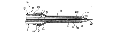
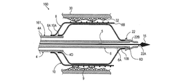
次に、図1及び図2を参照する。図1は、本発明のカテーテルの一実施形態に係る、バルーン及びスリーブを含むオーバー・ザ・ワイヤ型(OVT)バルーンカテーテルを示す断面図である。図2は、図1のカテーテルをII−II線に沿って切断した概略断面図である(図2ではガイドワイヤ14は図示していない)。
Reference is now made to FIGS. FIG. 1 is a cross-sectional view illustrating an over-the-wire (OVT) balloon catheter including a balloon and a sleeve, according to an embodiment of the catheter of the present invention. 2 is a schematic cross-sectional view of the catheter of FIG. 1 taken along line II-II (the
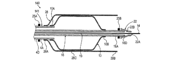
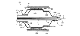
図3は、本発明のカテーテルの別の実施形態に係る、バルーン及びスリーブを含むオーバー・ザ・ワイヤ型バルーンカテーテルを示す断面図である。図4は、図3のカテーテルをIV−IV線に沿って切断した概略断面図である(図4ではガイドワイヤ14は図示していない)。
FIG. 3 is a cross-sectional view illustrating an over-the-wire balloon catheter including a balloon and a sleeve according to another embodiment of the catheter of the present invention. 4 is a schematic cross-sectional view of the catheter of FIG. 3 taken along the line IV-IV (the
図1及び図2に示したカテーテル2の実施形態では、バルーン10は折り畳まれており、カテーテル2の内側導管6の周囲に巻き付けられている(折り畳まれている)が、スリーブ8は折り畳まれておらず、折り畳まれた(巻き付けられた)バルーン10上に配置され、円形断面形状を有する一端が開口したチューブ状部分であることが好ましい(ただし必須ではない)。
In the embodiment of the catheter 2 shown in FIGS. 1 and 2, the
図3及び図4に示したカテーテル100では、カテーテル100は、内側導管6及び外側導管4を有するカテーテルシャフト101を含んでいる。カテーテル100はまた、バルーン10、スリーブ17、及びコネクタ部材12を含んでいる。バルーン10は折り畳まれており、カテーテル100の内側導管6の周囲に巻き付けられている(折り畳まれている)。しかし、
一方、カテーテル100のスリーブ17は、折り畳まれておらず円筒形状を有するカテーテル2のスリーブ8とは異なり、好ましくは(ただし必須ではない)、折り畳まれたバルーン10上に折り畳まれている(巻きつけられている)チューブ状または円筒状のスリーブである。すなわち、図4に最もよく見ることができるように、バルーン10及びスリーブ17の両方がカテーテル100の内側導管6上に折り畳まれている(巻き付けられている)。図4の断面図では、図示を明瞭にするために、バルーン10及びスリーブ17が比較的緩く折り畳まれた状態を図示しているが、カテーテル100の体内挿入前は、バルーン10及びスリーブ17は、内側導管6の外面6Aに図4に示した状態よりもタイトな状態で巻き付けられていることに留意されたい。
In the
On the other hand, the
上述したバルーン及びスリーブの2つの構成(バルーンが折り畳まれておりスリーブが折り畳まれていない実施形態と、バルーン及びスリーブの両方が折り畳まれている実施形態)は、本明細書中に説明されたオーバー・ザ・ワイヤ型(OVT)カテーテル、並びに、本明細書中に開示された全ての迅速交換型(RE)カテーテル及び多重導管型(マルチルーメン型)カテーテルを含む本発明の全てのカテーテルにおいて相互互換的に使用できることに留意されたい。 The two configurations of the balloon and sleeve described above (the embodiment in which the balloon is folded and the sleeve is not folded) and the embodiment in which both the balloon and sleeve are folded are described above. • Interchangeability in all the catheters of the present invention, including the wire (OVT) catheter, and all rapid exchange (RE) catheters and multi-conduit (multi-lumen) catheters disclosed herein. Note that it can be used for
図5〜図7は、図1のカテーテル2の一部の概略断面図であり、互いに異なる3つの操作段階中のカテーテル2の状態をそれぞれ示す。図7Aは、図7のカテーテルをVIIA−VIIA線に沿って切断した概略断面図である。 5 to 7 are schematic cross-sectional views of a part of the catheter 2 of FIG. 1, and show the state of the catheter 2 during three different operation stages. 7A is a schematic cross-sectional view of the catheter of FIG. 7 taken along the line VIIA-VIIA.
図1及び図2を参照して、カテーテル2は、カテーテルシャフト1と、膨張可能バルーン10と、スリーブ8と、コネクタ部材12とを含む。カテーテルシャフト1は、外側導管4と、外側導管4の内側に配置された内側導管6とを含む。外側導管4は、チューブ状導管であることが好ましい(ただし必須ではない)。外側導管4は、遠位端部4Dと近位端部4Pとを有する。内側導管6は、外側導管5のルーメン(内腔)内に配置される。また、内側導管6は、外側導管4のルーメン径よりも小さい外径を有するチューブ状導管であることが好ましい(ただし必須ではない)。内側導管6は、遠位端部6Dと近位端部6Pとを有する。内側導管6の遠位端部6Dは、外側導管4の遠位端部4Dを越えて延出(突出)している。内側導管6及び外側導管4は、これに限定されないが、例えば、ナイロン(登録商標)、ペバックス(登録商標)、ポリウレタン、ポリエチレンテレフタラート(PET)、ステンレス鋼などのフレキシブルな材料から作製することができる。内側導管6の近位端部6P及び外側導管4の近位端部4Pは、図1に示すように、コネクタ部材12に密封的に結合されている。近位端部6P及び近位端部4Pのコネクタ部材12への結合は、接合、熱接合、接着、または当分野で周知の他の結合方法により行うことができる。コネクタ部材12は、これに限定されないが、ポリマーや、金属または合金などの任意の適切な材料(例えば、これに限定されないが、ペバックス(登録商標)、ステンレス鋼、または他の任意の適切なエンジニアリングプラスチックまたはポリマーベースの構造材料)から作製することができる。
With reference to FIGS. 1 and 2, the catheter 2 includes a catheter shaft 1, an
コネクタ部材12は、その内部に2つの中空通路を有している。第1の中空通路16は、内側導管6のルーメンに開口しており、オーバー・ザ・ワイヤ型(OVT)カテーテルの分野で周知のように、コネクタ部材12のガイドワイヤ挿入ポート12Aを通じて内側導管6のルーメンにガイドワイヤ14を挿入及び挿通することを可能にしている。ガイドワイヤ14の端部14Dは、内側導管6の遠位端部6Dを越えて突出し、当分野で周知のように、カテーテル2の身体通路(例えば、これに限定されないが、血管)内への挿入を案内するのに使用される。第2の中空通路は、外側導管4の内面と内側導管6の外面との間に形成された環状空間20に膨張用流体を導入することを可能にするコネクタ部材12の流体ポート12B内に形成されている。
The
内側導管6及び外側導管4は両方ともコネクタ部材12に固定結合されているので、内側導管6は変位不能であり、外側導管4に対して軸方向に変位することができない。一方、内側導管6及び外側導管4のフレキシブルさに起因して、カテーテル2のシャフト1は横方向に曲がることができる。これにより、カテーテル2を、曲がりくねった身体通路(例えば、これに限定されないが、血管)内でガイドワイヤ14に沿って押し進めることが可能となる。
Since the
膨張可能バルーン10は、スリーブ8によって覆われている(または、本発明のカテーテルの特定の実施形態では、スリーブ8によって部分的に覆われている)。バルーン10は、適切なポリマーベース材料、例えば、これに限定されないが、ナイロン(登録商標)(好ましくはナイロン12(登録商標))、PET、ポリアミド(PA)(PA12(例えば、グリルアミド(登録商標)L25、L55)、PA11など)、ポリエーテルブロックアミド(PEBA)(例えば、ペバックス(登録商標)7233、7033、6333など)、様々な種類のグリルフレックス(登録商標)(例えば、ELG6260)などから作製された非応従性または半応従性のバルーンであることが好ましい(ただし必須ではない)。ただし、本明細書中に開示されたカテーテルのいくつかの実施形態では、膨張可能バルーンは、例えば、ゴムやラテックスなどの高応従性材料から作製してもよい(詳細については後述する)。なお、当分野で周知の、カテーテルバルーンの作製に適した他の任意の適切な生体適合性材料を使用して本願のバルーンを作製してもよい。
The
バルーン10は、一般的に、4〜25気圧の範囲の膨張圧力に耐えることができる。なお、とりわけ、バルーン寸法、バルーン壁厚、バルーンの作製材料、及びカテーテルの設計の特定目的に応じて、バルーン10を、4気圧よりも低いかまたは25気圧よりも高い膨張圧力に耐えることができるように作製してもよい。
バルーン10の一般的な寸法は、バルーン径が2〜8mm、バルーン全長が8〜300mm、バルーン壁厚が0.01〜0.1mmである。なお、上記の寸法は決して必須または限定的ではなく、とりわけ、カテーテルの設計の特定目的に応じて、上記の寸法よりも高いまたは低い値のバルーン全長、バルーン径、またはバルーン壁厚を用いてもよい。
The general dimensions of the
スリーブ8は、適切なポリマーベース材料、例えば、これに限定されないが、ナイロン(登録商標)(好ましくはナイロン12(登録商標))、PET、ポリアミド(PA)(PA12(例えば、グリルアミド(登録商標)L25、L55)、PA11など)、ポリエーテルブロックアミド(PEBA)(例えば、ペバックス(登録商標)7233、7033、6333など)、様々な種類のグリルフレックス(登録商標)(例えば、ELG6260)などから作製された非応従性または半応従性のスリーブであることが好ましい(ただし必須ではない)。なお、当分野で周知の、スリーブの作製に適した他の任意の適切な生体適合性材料を使用して本願のバルーンを作製してもよい。
The
一般的に、バルーンカテーテルの分野で周知の共通技術用語は下記のように定義される。 In general, common technical terms well known in the field of balloon catheters are defined as follows:
「負荷」は、構成要素(例えば、バルーン、導管、またはスリーブ)に作用する力または圧力と定義される。 “Load” is defined as the force or pressure acting on a component (eg, balloon, conduit, or sleeve).
「伸張性」は、負荷の印加後に、形状または寸法が元のサイズの少なくとも10%恒久的に変形し、かつ負荷作用下で塑性変形する構成要素、構造体、または材料を定義するのに用いられる。 “Extensible” is used to define a component, structure, or material that, after application of a load, is permanently deformed in shape or dimension by at least 10% of its original size and plastically deforms under the action of a load. It is done.
「非伸張性」は、負荷の印加後に、形状または寸法が、元のサイズまたは寸法の10%を超えて恒久的に変形しない構成要素、構造体、または材料を定義するのに用いられる。 “Non-extensible” is used to define a component, structure, or material that does not deform permanently beyond 10% of its original size or dimension after application of a load.
「コンプライアント(応従性)」は、負荷の印加後に、形状または寸法が元のサイズの少なくとも15%可逆的に変形し(例えば、径や長さなどが大きくなる)、かつ負荷作用下で超弾性変形する(ゴムのように変形する)構成要素、構造体、または材料を定義するのに用いられる。 “Compliant” means that after application of a load, the shape or dimension is reversibly deformed by at least 15% of the original size (for example, the diameter, length, etc. increase) and is superfluous under load. Used to define a component, structure, or material that is elastically deformed (deforms like rubber).
「セミコンプライアント(半応従性)」は、負荷の印加後に、形状または寸法が元のサイズの2〜15%の範囲で可逆的に変形し(例えば、径や長さなどが大きくなる)、かつ負荷作用下で弾性変形する構成要素、構造体、または材料を定義するのに用いられる。 “Semi-compliant” means that the shape or dimension is reversibly deformed within a range of 2 to 15% of the original size after application of a load (for example, the diameter or length becomes large), and Used to define a component, structure, or material that elastically deforms under load.
「ノンコンプライアント(非応従性)」は、負荷の印加後に、形状または寸法が元のサイズの0〜2%の範囲で可逆的に変形し(例えば、径や長さなどが大きくなる)、かつ負荷作用下で変形しないかまたは上記の範囲内で弾性変形する構成要素、構造体、または材料を定義するのに用いられる。 “Non-compliant” means that after application of a load, the shape or dimension is reversibly deformed in the range of 0 to 2% of the original size (for example, the diameter or length becomes large) And used to define a component, structure, or material that does not deform under load or elastically deforms within the above range.
上記の定義では、負荷の印加中に、材料、構成要素、または構造体に破壊や破断が生じないと仮定していることに留意されたい。 Note that the above definition assumes that the material, component, or structure does not break or break during application of the load.
下表1は、本願のバルーン及び/またはスリーブの作製に適した材料のリストである。表1では、材料は、物理的特性によって分類されている。

** PEBAX5533は、硬いかつ非加硫のゴムと同様の物理的特性を有する材料である。
上表1では、下記の略語は、下記の物理的特性を示すのに用いられている。
Sは、「伸張性」を示す。
NSは、「非伸張性」を示す。
Cは、「コンプライアント」を示す。
SCは、「セミコンプライアント」を示す。
NCは、「ノンコンプライアント」を示す。
SWは、「若干」を示す。
Table 1 below is a list of materials suitable for making the balloons and / or sleeves of the present application. In Table 1, materials are classified by physical properties.
** PEBAX5533 is a material that has physical properties similar to hard and unvulcanized rubber.
In Table 1 above, the following abbreviations are used to indicate the following physical properties:
S indicates “extensibility”.
NS stands for “non-stretchable”.
C indicates “compliant”.
SC stands for “semi-compliant”.
NC indicates “non-compliant”.
SW indicates “slightly”.
スリーブ8は、バルーン10が公称膨張径に膨張したときにバルーン10から印加される力に耐えることができる。スリーブ8はまた、とりわけ、スリーブの壁厚や、スリーブの作製材料の物理的特性を適切に選択することにより、バルーン10の膨張時にバルーン10を支持(または補強)してバルーン10が耐えることができる内圧を大きくすることができる。
The
スリーブ8の一般的な寸法は、スリーブ径が2〜15mm、スリーブ全長が8〜300mm、スリーブ壁厚が0.01〜0.1mmである。なお、上記の寸法は決して必須または限定的ではなく、とりわけ、カテーテルの設計の特定目的に応じて、上記の寸法よりも高いまたは低い値のスリーブ全長、スリーブ径、またはスリーブ壁厚を用いてもよい。例えば、カテーテルを末梢静脈の治療に使用する場合は、完全に開かれた状態でのスリーブ径と、公称膨張圧力でのバルーン径は、15mmよりも大きいこともあり得る(大きな末梢静脈または大静脈を治療する場合)。
The general dimensions of the
図5〜図7を参照して、バルーン10は、近位端部10Aと、遠位端部10Bとを有している。バルーン10の近位端部10Aは、外側導管4の遠位端部4Dの外面4Aに密封的に結合されており、バルーン10の遠位端部10Bは、内側導管6の外面6Aに密封的に結合されている。スリーブ8は、近位端部8Aと、遠位端部8Bとを有している。スリーブ8の近位端部8Aは、外側導管4の遠位端部4Dの外面4Aに密封的に結合されている。スリーブ8の遠位端部8Bは、内側導管6の外面6Aに結合されておらず、バルーン10の膨張時に内側導管6から径方向に離間する方向に自由に変位することができる。バルーン10の遠位端部10Bの内側導管6への結合、並びに、バルーン10の近位端部10A及びスリーブ8の近位端部8Aの両端部の外側導管4への結合は、接合、熱接合、超音波接合、任意の適切な接着剤を使用した接着、または当分野で周知の他の任意の結合方法を用いて行うことができる。
5 to 7, the
カテーテル2のバルーン10及びスリーブ8の構成は、図5に最もよく見ることができる。カテーテル100の、バルーン10及びスリーブ17の構成は、図3及び図4に最もよく見ることができる。この初期状態(折り畳まれた状態または巻き付けられた状態)では、バルーン10は折り畳まれているので(図2を参照)、折り畳まれたバルーン10とバルーン10を取り囲むスリーブ8(折り畳まれていない)のクロッシングプロファイルは小さくなり、これにより、治療対象の身体通路または血管のアテロームまたは他の病変部、狭窄部または閉塞部を通過させやすくなる。同様に、カテーテル100(図3)では、バルーン10及びスリーブ17は両方とも折り畳まれており、カテーテル100のシャフト101の内側導管6の外面6Aに巻き付けられているので、バルーン10及びスリーブ17のクロッシングプロファイルは小さくなり、これにより、治療対象の身体通路または血管のアテロームまたは他の病変部、狭窄部または閉塞部を通過させやすくなる。
The configuration of the
図2及び図4に示した互いに異なる2つの折り畳み構成により実現された低クロッシングプロファイルは、狭窄領域またはアテローム性血管内のアテロームまたはプラーク内に挿入及び/または挿通する際の、カテーテル2及び100の各遠位端部の通過性(passability)及び押し込み能力(pushability)を向上させる。
The low crossing profile achieved by the two different folded configurations shown in FIGS. 2 and 4 is that of
図5に示すように、(バルーンを膨張させる前の)折り畳まれた(または巻き付けられた)状態では、バルーン10は内側導管6の外面に隣接して位置しており、バルーン10の近位端部10Aは外側導管4の遠位端部4Dに密封的に結合している。スリーブ8は、バルーン10の一部または大部分の上側(表面)に位置し、バルーン10の近位端部10Aから遠位端部10Bまでの長さの大部分を覆う。あるいは、本発明のカテーテルの別の実施形態では、バルーン10の全長が、スリーブ8により覆われ、スリーブ8内に位置することとなる(図14及び図22を参照)。本発明のカテーテルのさらに別の実施形態では、スリーブの遠位端部は、バルーンの遠位端部を越えて遠位方向に延出している(図23及び図24を参照)。
As shown in FIG. 5, in the folded (or wrapped) state (before the balloon is inflated), the
スリーブ8の近位端部8Aは、外側導管4の遠位端部4Dに密封的に結合されている(図5〜図7参照)。あるいは、本発明のカテーテルの別の実施形態では、バルーン10の近位端部10Aは、外側導管4の遠位端部4Dに密封的に結合されており、スリーブ8の近位端部8Aは、バルーン10の近位端部10Aに密封的に結合されている(図36のカテーテル500で最もよく見える)。
The
スリーブ8の遠位端部8Bは、バルーン10の遠位端部10Bから少し離れた位置に位置される(外側導管4に沿って)。図2及び図4に示した、初期状態(バルーンを膨張させる前の状態)での、互いに異なる2つの構成において、スリーブ8は、バルーン10上に配置することができる。図2は、図1をII−II線に沿って切断した断面図である。バルーン10は、内側導管6上に折り畳まれている(巻き付けられている)。スリーブ8は、チューブ状のスリーブであり、内側導管6の外面に巻き付けられた折り畳まれたバルーン10上にスリーブ8が密着するように、折り畳まれたバルーン10の最大径寸法よりも若干大きい初期径を有している。カテーテル2の使用時は、膨張ステップにおいて(図6参照)、(図1の流体ポート12Bの通路18を通じて膨張用流体を導入することによって)バルーンを膨張させるとともに、膨張したバルーン10によってスリーブ8を拡張する(広げる)。
The
一般に、カテーテル2においては、バルーン10の膨張前は、スリーブ8の初期径(非拡張時の径)は、完全膨張時のバルーン10の公称径よりも小さい。一方、バルーン10の膨張時は、バルーン10からスリーブ8に力が加えられ、それにより、スリーブ8は押圧されて伸張及び拡張し、スリーブ8の径は増加する。本発明のカテーテル2では、バルーン10の膨張時に、スリーブ8が初期の非拡張状態(図1及び図2参照)から、非拡張状態(または拡張前)のスリーブ径よりもスリーブ径が大きくなる拡張状態まで伸張及び拡張することができるように、スリーブ8は伸張可能なコンプライアント材料から作製するとよい。スリーブ8の拡張状態は、図6に最もよく見ることができる。
In general, in the catheter 2, before the
図3に戻って、本発明のカテーテルのスリーブの別の構成が、図3及び図4の概略断面図に示されている。カテーテル100では、バルーン10は、内側導管6上に折り畳まれており、スリーブ17は、バルーン10上に折り畳まれている。バルーン膨張ステップでは、バルーン10は膨張状態に膨張し、スリーブ17を径方向外側に押圧する。これにより、折り畳まれた状態のスリーブ17は展開(拡張)され展開状態(拡張状態)となる。折り畳まれたバルーン10上に折り畳まれた展開可能なスリーブ8を含む実施形態には、互いに異なる2つの構成があることに留意されたい。第1の実施形態では、完全に展開された(完全に広げられた)スリーブ17の内径は、バルーン10の(膨張時の)公称外径と等しいかまたは前記公称外径よりも若干大きい。この実施形態では、公称膨張圧力を用いてバルーン10を膨張させたとき、バルーン10は、スリーブ17を大幅に伸張させることなく、スリーブ17を広げる。この実施形態では、完全展開状態のスリーブ17の内径が、完全膨張時のバルーン10の公称外径よりも十分に大きくなるように、スリーブ17はノンコンプライアント材料または非伸張性材料から作製するとよい。
Returning to FIG. 3, another configuration of the catheter sleeve of the present invention is shown in the schematic cross-sectional views of FIGS. In the
第2の実施形態では、完全展開状態のスリーブ17の径は、公称膨張圧力で膨張させたときのバルーン10の径よりも大幅に小さい。この実施形態では、公称膨張圧力を用いてバルーン10を膨張させたとき、膨張したバルーン10は、まず、折り畳まれたスリーブ17を押し広げて展開し、その後、スリーブ内径が展開されたが未伸張のスリーブ内径よりも大きくなるまで、スリーブ17を伸張及び拡張する。この第2の実施形態では、スリーブ17は、まず、伸張されることなく、スリーブ内径が膨張状態のバルーン10の外径と等しくなるまで展開される。バルーン10のさらなる膨張によるバルーン10の外径のさらなる増加により、スリーブは、バルーンが公称膨張圧力に達するまで伸張され、バルーンが公称膨張圧力に達したらスリーブの拡張は終了する。この第2の実施形態では、スリーブ17は、展開状態(ただし、非伸張)において、スリーブ17の初期径よりも大幅に大きい径まで伸張及び拡張することができる材料から作製される。この第2の実施形態では、スリーブは、セミコンプライアント材料及び/または部分的に伸張可能な材料、例えば上表1に示した必要とされる特性を有する任意の材料から作製するとよい。
In the second embodiment, the diameter of the fully deployed
本発明のカテーテルのいくつかの実施形態では、スリーブ8または17及び/または後述する他の任意のスリーブは、ある程度は伸張可能であるが、それ以上は伸張しない状態(特定の制限または閾値径)に達するか、またはそれ以上の伸張に対して強い抵抗を示す(前記閾値径よりも伸張させるためにはより強い力を必要とする)材料から作製することができる。このような性質は、伸張されたスリーブが膨張バルーンの形状及び/または径を制御するので、バルーン10がハイコンプライアント材料、例えばラテックス(登録商標)などから作製されたカテーテルにおいて特に有用である。そうでなければ、(スリーブが存在しない場合は、)より丸い形状に不必要に膨張するか、さらには、最大許容膨張圧力よりも高い圧力が偶発的に印加されたときに破裂することがある。上記のスリーブは、バルーンの過膨張あるいは破裂を防止または減少させるための追加的な安全機構として機能することができる。
In some embodiments of the catheter of the present invention, the
任意選択で(必須ではないが)、カテーテル2は、内側導管6の遠位端部6Dに取り付けられる柔軟性先端部22を含む。柔軟性先端部22は、円錐状または円錐台形状の形状を有する。なお、所望に応じて、他の形状、これに限定されないが、例えば、中空であり、開口を有し、かつ丸み帯びたキャップ状(図示せず)の形状であってもよい。柔軟性先端部22は、柔軟かつ曲げやすい材料、例えば、これに限定されないが、ペバックス(登録商標)5533、ペバックス(登録商標)6333、または同様の柔軟性TPU(例えばポリウレタン)などから作製するとよい。柔軟性先端部22(または後述する柔軟性先端部27)の材料は、X線不透過性充填剤、これに限定されないが、例えば硫酸バリウム(BaSO4)などを含有することが好ましい(ただし必須ではない)。このようなX線不透過性充填剤は、カテーテルを位置決めするために血管造影法を用いる場合に、バルーンの遠位端部のおおよその位置を示すX線不透過性マーカとして使用することができる。
Optionally (but not necessarily), the catheter 2 includes a
柔軟性先端部22は、ガイドワイヤ14が柔軟性先端部22内に形成された中空通路22Bを通って柔軟性先端部22の遠位端部に形成されたオリフィス22Aから出ることができるように、内側導管6の遠位端部6Dに接着、接合、または他の方法で固定的または着脱可能に取り付けられる(例えば、これに限定されないが、接着、接合、熱接合、または接着剤または同様のものを使用しない取り付けにより)。
The
柔軟性先端部22は、身体通路壁または血管壁を傷つけることなく、曲がったまたは曲がりくねった身体通路または血管にカテーテルを通すことを容易にする。なお、柔軟性先端部22は任意的なものであり、本明細書に開示された本発明のカテーテルは、柔軟性先端部22を使用せずに構成及び使用してもよい。
The
使用時は、カテーテル2及び100の使用者は、当分野で周知のように、適切なカニューレまたは身体の他の適切な挿入口を通してガイドワイヤ14を血管系に挿入する。使用者は、血管内でガイドワイヤ14を、ガイドワイヤ14の遠位端部が治療対象領域に到達するまで前進させる。その後、ガイドワイヤ14に沿わして、カテーテル2または100を血管内に挿入する。この段階では、バルーン10は、図1〜図4に示したような、小さなクロッシングプロファイルを有する初期状態(バルーンを膨張させる前の状態)にある。図1及び図5に詳細に示すように、カテーテル2または100の遠位端部が治療対象領域に到達したとき、バルーン10は、治療対象のアテロームまたは狭窄部に適切に位置する。
In use, the user of
その後、使用者は、コネクタ部材12の流体ポート12Bに接続させた適切なインデフレータ(図示せず)または膨張用流体充填済みシリンジ(図示せず)を使用して、バルーン10内に適切な膨張用流体(図示せず)を加圧下で導入することによりバルーン10を膨張させる。膨張用流体の導入圧力は、バルーン10及びスリーブ8の寸法、壁厚、及び材料に応じて異なる。一般に、バルーンの膨張圧力は、4〜25気圧の範囲であり得る。なお、バルーンの膨張圧力は、とりわけ、用途並びにバルーンの種類及び寸法に応じて、上記の圧力範囲とは異なっていてもよい(より低いまたはより高くてもよい)。流体ポート12Bの通路18に膨張用流体を注入することにより、バルーン10を膨張状態まで膨張させることができ、それにより、図6に詳細に示すように、スリーブ8を広げる(展開する)ことができる。スリーブ8の外面の部分8Cは、血管壁30に押し付けられ、アテローム(またはプラーク、または他の閉塞物)を圧縮して通路を広げて、血管の内腔の開断面積を大きくする。任意選択で(必須ではないが)、この段階で、当分野で周知のように、バルーン10及びスリーブ8の膨張及び拡張により、スリーブ8上に配置されたステント(図5〜図7では図示していない)を展開して血管壁30に押し付けて配置してもよい。バルーン展開可能ステントの分野で周知のように、このような任意選択のステント展開ステップでは、任意の種類の適切なバルーン展開可能ステントを使用することができる。血管内でステントを展開するステップを説明する特定の実施形態は、図28〜図30を参照して後述する。
The user then uses a suitable indeflator (not shown) connected to the
図6に示したカテーテルの状態では、バルーン10が膨張状態にあるときに、バルーン10の遠位端部10Bが、スリーブ8の遠位端部8Bを越えて遠位方向に延出していることに留意されたい。しかし、このことは、本発明のカテーテルの実施には必須ではなく、本発明のカテーテルの他の実施形態では、バルーン膨張時のバルーンの遠位端部とスリーブの遠位端部との関係が、図6に示した関係とは異なるように構成することができる(例えば、図24及び図25のカテーテル140及び150のスリーブとバルーンの配置を参照)。
In the state of the catheter shown in FIG. 6, when the
血管内の病変部または狭窄部の治療後、当分野で周知のように、例えば、流体ポート12Bに接続されたストップコックまたはバルブ(図示せず)を適切に開くか、または流体ポート12Bに接続されたバルーン膨張用のインデフレータまたはシリンジを適切に圧抜きすることにより、流体ポート12Bの通路18を介してカテーテル2、100内の圧力を減少させることによりバルーン10を収縮させる。バルーン10を収縮させると、バルーン10とスリーブ8との間に、環状の開放キャビティ40が形成される(図7及び図7Aに最もよく見ることができる)。キャビティ40は、スリーブ8の壁部の内面と、バルーン10の外面との間に画成される。図7に最もよく見ることができるように、キャビティ40の遠位部分は、血管の内側ルーメンに開放されている。
After treatment of a lesion or stenosis in a blood vessel, as is well known in the art, for example, a stopcock or valve (not shown) connected to
次に、図7のカテーテルの概略断面図であり、血管30をVIIA−VIIA線に沿って切断した図7Aを参照すると、バルーン10の収縮ステップ後のバルーン10及びスリーブ8の状態が示されている。バルーン10の収縮後に開放キャビティ40が形成されることにより、血管のルーメン中の血液及びデブリ34(例えば、プラークデブリ)をキャビティ40内に引き込む吸引力(吸引作用)が生じる。このことは、血流中に入るデブリ34の量を減らすことができるので有益である。キャビティ40の形成中に生じた吸引力(吸引作用)により、キャビティ40内にデブリ34を捕捉することができる。捕捉されたデブリ34は、その後、カテーテル2、100と共に体内から除去される。これにより、有益なことに、患者の塞栓症のリスクを大幅に減少させることができる。図7Aの概略図では、収縮して平たくなったバルーン10は、(図示を明瞭にするために)図式的に示されていることに留意されたい。収縮したバルーンは、実際には、図7Aに示した図式的な形状とは異なる様々な収縮形状を有することができ、実際には、非対称及び/または非均一な平坦プロファイルを示し、さらにはバルーン壁部がキンクしたりしわくちゃになったりすることもあり得ることは、当業者であれば理解できるであろう。
Next, FIG. 7A is a schematic cross-sectional view of the catheter of FIG. 7 and shows the state of the
バルーン10の収縮後、カテーテル2または100を近位方向に引っ張ることにより、カテーテル2または100をキャビティ40内に捕捉されたデブリ34と共に挿入ポートを通じて血管系から引き出すことができる。
After the
次に、図8及び図9を参照する。図8は、スリーブの遠位端部を初期状態(バルーンを膨張させる前の状態)に保つのに有用なスリーブ部保持部材を備えた柔軟性先端部を含むカテーテルの一実施形態を示す概略断面図である。図9は、図8のカテーテルのバルーン膨張後の状態を示す概略断面図である。 Reference is now made to FIGS. FIG. 8 is a schematic cross-section illustrating one embodiment of a catheter including a flexible tip with a sleeve retaining member useful for maintaining the distal end of the sleeve in an initial state (prior to inflating the balloon). FIG. 9 is a schematic cross-sectional view showing a state of the catheter of FIG. 8 after balloon inflation.
図8及び図9に示すカテーテルの実施形態では、カテーテル110は、柔軟性先端部22の代わりに柔軟性先端部27を含むこと以外は、図1のカテーテル2と同様の構造を有する。柔軟性先端部27は、カテーテル110の内側導管6の遠位端部6Dに取り付けられる。柔軟性先端部27は、柔軟性先端部27を貫通する中空通路27Bと、ガイドワイヤ14(または医療若しくは診断デバイス)が柔軟性先端部27を通過することを可能にするためのオリフィス27Aとを有している。カテーテル100の柔軟性先端部22について上記に詳述したように、柔軟性先端部27は、円錐状(または、テーパ状または丸みを帯びた)遠位部分27Cを有する。柔軟性先端部27は、保持部材27Dをさらに有する。保持部材27Dは、柔軟性先端部27のカップ様部分(cup-like portion)として、遠位部分27Cの壁部よりも薄い壁部を有するように形成されることが好ましい(ただし必須ではない)。図8を参照して、バルーン10及びスリーブ8が初期の非膨張状態(カテーテルの使用前の状態)である場合、保持部材27Dは、その薄い壁部がスリーブ8の遠位端部8Bを取り囲むようにしてスリーブ8の遠位端部8B上に位置しており、スリーブ8の遠位端部8Bを、径方向に開かないように、かつバルーン10の遠位端部10Bの外面に隣接するように保持及び固定している。保持部材は、スリーブ8及び/またはバルーン10を保持することができ、それにより、内側導管6上に折り畳まれているバルーン10(図2及び図4参照)が偶発的に広がること、及び/またはバルーン10上に折り畳まれているスリーブ8(図4参照)が半径方向に広がることを防止することができる。保持部材27の長さ、径、及び形状は、とりわけ、スリーブの長さ、折り畳まれたバルーンの長さ、及び折り畳まれたバルーン及び/または折り畳まれたスリーブ(スリーブが折り畳まれる構成では)の径に応じて様々であり得ることに留意されたい。
In the embodiment of the catheter shown in FIGS. 8 and 9, the
また、この構成は、スリーブ8が偶発的に変位したり外れたりすることを防止したり、カテーテルの体内への挿入前または挿入中あるいは血管系または身体通路内での移動中に、スリーブ8の遠位端部8Bが、早まって横方向(半径方向)に広がってカテーテルの挿入を妨げる可能性を低減させたりすることができる。柔軟性先端部27の使用により、バルーン10及びスリーブ8を、低クロッシングプロファイルを有する適切にタイトに巻き付けられた(折り畳まれた)形状で血管系に挿入し、カテーテルの遠位端部が治療対象部位に到達し、バルーン10が治療対象領域に適切に位置決めされるまで血管系内で移動させることが容易になる。
This configuration also prevents the
図9を参照して、カテーテル110が治療対象領域(例えば、アテローム性動脈領域または動脈狭窄部)まで適切に導かれ、バルーン10が適切に位置決めされると、図6に示したカテーテル2に関して上述したようにして、バルーン10を膨張させる。バルーン10が膨張すると、スリーブ8の遠位端部8Bは、柔軟性先端部27のスリーブ保持部材27Dの近位部分の薄い壁部を(側方向に)押しのけ、これにより、スリーブ8の遠位端部8Bは、スリーブ保持部材27Dによる保持から解放され、図9に最もよく見ることができるように、バルーン10はその膨張状態まで膨張する。
Referring to FIG. 9, once the
2つの異なる種類の柔軟性先端部22及び27は、任意選択であり、上述した利点を実現するために、本明細書中で説明された任意のカテーテルにおいて相互互換的に使用可能であることに留意されたい。なお、本明細書中の任意のカテーテルは、柔軟性先端部を使用せずに構成及び実施することが可能である。
The two different types of
本明細書中に開示されたカテーテル(これに限定されないが、カテーテル2、52、100、110、120、130、140、150、160、170、202、230、250、260、270、280、352、400、及び500を含む)は、カテーテルシャフトの軸方向に変位する部分を含んでいないという利点を有しており、そのため、作製が容易であり、安価であり、使用が簡単である。なお、カテーテルの内側導管に追加的な機能を追加する追加的なカテーテル構成を実施することも可能である。
The catheters disclosed herein (but are not limited to
ここで図10を参照する。図10は、本発明の一実施形態に係る迅速交換型バルーンカテーテルを示す概略断面図である。この迅速交換型バルーンカテーテルは、固定され変位不能なかつ角度付けされた(曲がった)内側導管と、膨張可能バルーンと、スリーブとを含む。図10は、バルーンの膨張後に、バルーンを収縮させた状態を示している。 Reference is now made to FIG. FIG. 10 is a schematic sectional view showing a rapid exchange type balloon catheter according to an embodiment of the present invention. The rapid exchange balloon catheter includes a fixed, non-displaceable and angled (bent) inner conduit, an inflatable balloon, and a sleeve. FIG. 10 shows a state in which the balloon is deflated after the balloon is inflated.
迅速交換型カテーテル202は、外側導管204と、外側導管204内に配置され角度付けされた内側導管206とを有するシャフト201を含む。カテーテル202はまた、シャフト201の遠位端部に結合されたバルーン10と、シャフト201の遠位端部に結合されたスリーブ8と、シャフト201の近位端部に取り付けられた中空のコネクタ部材212とを含む。外側導管204の近位端部204Pは、コネクタ部材212の遠位端部に形成された凹部212Rに、接合、接着、溶接、超音波溶接などにより、強固にかつ密封的に結合されている。
The
バルーン10は近位端部10Aを有し、近位端部10Aは、外側導管204の遠位端部204Dに、上記に詳述した結合、接合、接着または溶接方法のいずれかを用いて接合または接着などにより密封的に結合されている。バルーン10は遠位端部10Bを有し、遠位端部10Bは、内側導管206の遠位端部206Dに、上記に詳述した結合、接合、接着または溶接方法のいずれかを用いて接合または接着などにより密封的に結合されている。したがって、バルーン10は、外側導管204のルーメン220を通じて流体ポート212Aに流体連通されている。
The
上記に詳細したように、膨張用流体(図示せず)は、流体ポート212Aに接続されたインデフレータ(図示せず)または膨張用流体が充填されたシリンジ(図示せず)を使用して流体ポート212Aから注入される。注入された膨張用流体は、流体ポート212Aに形成された通路216及び外側導管204のルーメン220を通ってバルーン10のルーメン内に導入される。
As detailed above, the inflation fluid (not shown) is fluidized using an indeflator (not shown) connected to the
内側導管206は、真っ直ぐな部分206Bと、真っ直ぐな部分206Bに対して或る角度で傾斜した角度付けされた(曲がった)部分206Aとを有している。角度付けされた部分206Aは、外側導管204の壁部を貫通している。また、角度付けされた部分206Aは、流体ポート212Aの開口部216からルーメン220内に導入された膨張用流体が漏出するのを防ぐために、外側導管204の壁部に密封的に結合されている。中空の柔軟性先端部22は(任意選択であり、必須ではない)、内側導管206の遠位端部206Dに結合されている(図1の柔軟性先端部22に関して詳述したように)。
The
外側導管204の壁部には、内側導管206の角度付けされた部分206Aの近位端部と連通する開口部15が形成されている。開口部15は、内側導管206のルーメン205内へのガイドワイヤ14の挿入を可能にする。ガイドワイヤ14は、柔軟性先端部22の遠位端部に形成された開口部22Aから出るまで、ルーメン205内を押し進められる。バルーン10及びスリーブ8は、図1及び図2のカテーテル2のバルーン10及びスリーブ8の初期形態と同様の巻き付けられた(折り畳まれた)状態で配置することができる。あるいは、バルーン10及びスリーブ8の配置は、図3及び図4のカテーテル100のバルーン10及びスリーブ17の配置と同じであってもよい。
The wall of the
迅速交換型カテーテル202の様々な操作ステップは、カテーテル2、100、110の使用時及び操作時は、ガイドワイヤ14は、カテーテルの近位端に設けられたガイドワイヤ挿入ポート12Aから内側導管6のルーメン内に挿入したが、迅速交換型カテーテル202の使用時は、ガイドワイヤ14は、シャフト201の開口部15から内側導管206のルーメン205内に挿入されることを除いては、図1〜図9を参照して前述したオーバー・ザ・ワイヤ型(OVT)カテーテル2、100、110の操作時のステップと同様である。なお、カテーテル202の操作時の他のステップ、例えば、バルーン10を折り畳んだ状態で(図2及び図4参照)カテーテルを体内または血管系へ挿入するステップ、血管系内でカテーテルを治療対象領域に達するまで移動させるステップ、スリーブ8上に配置された(任意選択の)ステントを展開してまたは展開せずに、血管内の狭窄部またはアテローム性プラーク32を治療すべくバルーン10及びスリーブ8を広げるためにバルーン10を膨張させるステップ(図6及び図9参照)、膨張したバルーン10を収縮させて、収縮したバルーン10とスリーブ8との間に、デブリ34を捕捉するためのキャビティ40を形成するステップ(図7参照)、カテーテル及びカテーテルに捕捉されたデブリ34を体外に引き出すステップは、カテーテル2、100、110について上記に前述した対応する操作ステップと同様である。
The various operational steps of the
次に、本発明のさらに別の実施形態に係るオーバー・ザ・ワイヤ型カテーテルの一部を示す概略断面図である図11及び図12を参照する。このオーバー・ザ・ワイヤ型カテーテルは、バルーンとスリーブとの間に、物質(例えば、薬剤、医薬組成物、治療用組成物)が配置されている。図11及び図12は、カテーテルの互いに異なる2つの操作ステップを示している。 Reference is now made to FIGS. 11 and 12, which are schematic cross-sectional views showing a portion of an over-the-wire catheter according to yet another embodiment of the present invention. In this over-the-wire catheter, a substance (for example, a drug, a pharmaceutical composition, or a therapeutic composition) is disposed between the balloon and the sleeve. 11 and 12 show two different operating steps of the catheter.
図11を参照して、カテーテル250は、内側導管6及び外側導管4を有するシャフト251を含む。カテーテル250はまた、シャフト251に結合されたバルーン10及びスリーブ80を含む。スリーブ80は、その壁部に形成された複数の穿孔80Cを有する。薬剤、医薬組成物、治療用組成物、または診断用物質90が、バルーン10とスリーブ80との間に配置されている。バルーン10の近位端部10Aは、図1に関して上記に詳述したように、外側導管4の遠位端部4Dに密封的に結合されている。有孔スリーブ80の近位端部80Aは、外側導管4の遠位端部4Dに密封的に結合されている。有孔スリーブ80の遠位端部80Bは、開口端であり、バルーン10の遠位端部10Bを覆っている。有孔スリーブ80は、多孔性材料から作製されるか、多孔性材料を含むか、または、穿孔(または開口)80Cが形成されたスリーブであり得る。また、有孔スリーブ80は、バルーンの膨張時にバルーン及びスリーブ間に収容された物質をスリーブの外面に押し出すことを可能にする開放キャビティを有するスポンジ様構造を有する材料から構成してもよい。
Referring to FIG. 11, the
穿孔(または開口)80Cの径の通常の範囲は、0.001〜0.5mmである(ただし必須ではない)。なお、とりわけ、カテーテルによって分配される薬剤または医薬組成物の種類、化学的特性または物理的特性(これに限定されないが、例えば粘度など)に応じて、上記の範囲よりも小さいまたはより大きい径であってもよい。穿孔80Cは、円形断面を有するか、または任意の所望の断面形状の非円形断面を有し得る。非円形断面の有孔スリーブ80では、穿孔の平均断面積は、0.001〜0.5mmの範囲の径を有する円形断面を有する穿孔の断面積と同様であり得るが、とりわけ使用される物質90の粘度、押し出し性及び/または他の流動特性に応じて、それよりも大きいまたは小さい断面積であってもよい。
A typical range for the diameter of the perforations (or openings) 80C is 0.001 to 0.5 mm (but not essential). It should be noted that the diameter may be smaller or larger than the above range, depending on, inter alia, the type of drug or pharmaceutical composition to be dispensed by the catheter, chemical properties or physical properties (including but not limited to viscosity, etc.). There may be. The
図12を参照して、バルーン10及びスリーブ80が初期状態(カテーテルの使用前の状態、またはバルーン10を膨張させる前の状態)にある場合、バルーンが膨張前状態にある限りは、スリーブ80の穿孔80Cの径が比較的小さいこと、及びバルーン10及びスリーブ80がタイトに折り畳まれた状態であることに起因して、薬剤、医薬組成物、または治療物質90は、バルーン10とスリーブ80との間に強固に保持される。この構成により、薬剤、医薬組成物、または治療用物質90が誤って移動することを防止し、カテーテル250の体内への挿入前または挿入中、あるいはカテーテル250を血管系または他の身体通路内で移動させるときに、薬剤、医薬組成物、または治療用物質90が放出される可能性を低減させる。このことにより、バルーン10及びスリーブ80、並びにそれらの間に配置された薬剤、医薬組成物、または治療用物質90を、低クロッシングプロファイルを有する適切にタイトに折り畳まれた(巻き付けられた)状態で、カテーテルの遠位端部が治療対象部位に到達し、かつバルーンが治療対象領域に適切に位置するまで、血管系内に挿入することが可能となる。
Referring to FIG. 12, when the
図11に戻って、カテーテル250が治療対象領域(例えば、アテローム性動脈領域または動脈狭窄部)まで適切に導かれ、バルーン10が適切に位置決めされると、図6に示したカテーテル2に関して上述したようにして、バルーン10を膨張させる。バルーン10が膨張すると、バルーン10とスリーブ80との間に配置された物質90は、バルーン10の膨張による力を受けて、スリーブ80の穿孔80Cから押し出され、血管30内、あるいはスリーブ80の外面に隣接する任意の病変部、プラーク、及び/またはアテロームに対して投与される。図12に最もよく見えるように、バルーン10をその公称膨張径まで膨張させると、スリーブ80は膨張したバルーン10によって広げられ、血管壁30の病変領域、例えばプラーク32に接触するかまたは少なくとも極めて接近し、そして、物質90は、血管の治療対象領域上に押し出されるか、または治療対象領域に接触させるべく放出または拡散させられる。
Returning to FIG. 11, once the
本発明のオーバー・ザ・ワイヤ型カテーテル、迅速交換型カテーテル、マルチルーメン(多重導管)カテーテルを含む本明細書中に開示された様々な種類のカテーテルに対して、非有孔スリーブを適切な有孔スリーブに置き換え、カテーテルのバルーン10と有孔スリーブ80との間に所望の物質、薬剤、治療用組成物、診断用組成物、または他の任意の物質または組成物を配置することにより、有孔スリーブ80と薬剤、医薬組成物、または治療用物質90との併用が適用可能であることに留意されたい。
Non-perforated sleeves are suitable for the various types of catheters disclosed herein, including the over-the-wire catheters, rapid exchange catheters, and multi-lumen catheters of the present invention. Replace with a perforated sleeve and place the desired substance, drug, therapeutic composition, diagnostic composition, or any other substance or composition between the
例えば、図13は、バルーンと有孔スリーブとの間に、薬剤、医薬組成物または物質が配置された迅速交換型カテーテルの概略断面図である。 For example, FIG. 13 is a schematic cross-sectional view of a rapid exchange catheter with a drug, pharmaceutical composition or substance placed between a balloon and a perforated sleeve.
図13のカテーテル230は、迅速交換型カテーテルであり、コネクタ部材212と、内側導管204及び図10のカテーテル202に関して上記に詳述した角度付けされた内側導管206を有するカテーテルシャフト231とを含む。カテーテル230はまた、外側導管204の遠位端部204Dに密封的に結合された近位端部Aと、内側導管206の遠位端部206Dに密封的に結合された遠位端部10Bとを有するバルーン10を含む。カテーテル230はまた、複数の穿孔80Cを有する有孔スリーブ80を含む。図13に示したカテーテル230の実施形態では、有孔スリーブ80の近位端部80Aは、バルーン10の近位端部10Aが結合されるバルーン結合領域に近位するスリーブ結合領域において、外側導管204の遠位端部204Dに結合されている。なお、カテーテル230の別の実施形態では、有孔スリーブ80の近位端部80Aは、(接着、溶接、超音波溶接、または当分野で周知の他の任意の適切な結合方法により)バルーン10の近位端部10Aに結合させてもよい(この代替構成は図13では図示していないが、図36のカテーテル500を参照されたい)。図13に示すように、カテーテル230はまた、バルーン10と有孔スリーブ80との間に配置された物質または組成物90を含む。
The
本発明の薬剤/物質含有カテーテルの全ての実施形態と同様に、物質(または組成物)90は、任意の所望の物質または複数の物質の組み合わせ、例えば、これに限定されないが、例えば、1若しくは複数の物質、1若しくは複数の治療用物質、1若しくは複数の診断用物質、1若しくは複数の薬学的に許容される担体物質、1若しくは複数の遅延放出組成物、及びそれらの任意の組合せを含み得ることに留意されたい。物質90に含まれ得る成分のいくつかの非限定的な例としては、治療用物質、診断用物質、薬剤、治療用組成物、治療薬、診断用組成物、生理学的活性薬剤、生化学的活性薬剤、1若しくは複数の生細胞、DNA、RNA、核酸、治療部位の細胞に遺伝物質を送達するためのベクター、抗炎症薬、抗再狭窄剤、細胞増殖抑制剤、平滑筋増殖抑制剤(例えば、パクリタキセル、シロリムス(ラパマイシン)、エベロリムスなど)、血管作用薬、血管拡張薬、血管収縮薬、抗生物質、抗凝固薬、血小板凝集阻害薬、線維化抑制薬、薬学的に許容される担体、脂質ベースの担体、及びそれらの任意の組合せがある。
As with all embodiments of the drug / substance-containing catheter of the present invention, the substance (or composition) 90 can be any desired substance or combination of substances, such as, but not limited to, for example, 1 or Including multiple substances, one or more therapeutic substances, one or more diagnostic substances, one or more pharmaceutically acceptable carrier substances, one or more delayed release compositions, and any combination thereof Note that you get. Some non-limiting examples of components that can be included in the
物質(または組成物)90は、任意の薬学的に許容される担体、これに限定されないが、任意の追加的な薬学的活性成分または薬剤を溶液または懸濁液中に保持する粘性液体形態またはゲル形態の親水性担体または疎水性担体を含み得ることに留意されたい。物質または組成物90の粘性または押し出し性は、カテーテルの保管中(使用前)及び/またはカテーテルの使用時におけるバルーン10を膨張させる前の段階で、穿孔80Cから物質または組成物90が過度に漏出しないようなものにする。なお、物質または組成物90の流動特性、押し出し性、及び粘性は、バルーン10が公称膨張圧力下で膨張したときにバルーン10の膨張によって作用する力により、少なくとも一部の物質90が穿孔80Cを通って押し出されるのに十分なものにする。物質90の粘性、押し出し性、及び他の流動特性は、薬学的活性成分を物質90中に溶解及び/または懸濁するのに使用される担体の種類を選択することにより、また、溶解及び/または懸濁される活性成分の量と使用される担体の量との比率を適切に調節することにより制御することができる。さらに、物質90の流動特性、粘性、及び押し出し性は、薬学的に許容可能な流動性調整剤または粘性調整剤の添加によって調節可能である。
The substance (or composition) 90 can be any pharmaceutically acceptable carrier, including but not limited to a viscous liquid form that holds any additional pharmaceutically active ingredients or agents in solution or suspension. Note that gel-form hydrophilic or hydrophobic carriers may be included. The viscosity or extrudability of the substance or
使用時のカテーテル230の使用方法は、カテーテル202及びカテーテル205について上述した使用方法と同様である。カテーテルを体内に挿入し血管を通じて治療部位へ導くステップ、バルーン10を膨張させるステップ、アテロームまたは病変部を治療するステップ、バルーン10を収縮させるステップ、収縮したバルーン10とスリーブ80との間に形成されたキャビティ内にデブリ34を捕捉するステップ、及びカテーテルを体内から引き出すステップは、図10の迅速交換型カテーテル202について上記に詳述した通りである。物質(または組成物)90を、穿孔80Cを介して病変部、治療対象の血管領域、またはアテローム32に投与するステップは、図11及び図12のカテーテル250について上記に詳述した通りである。
The usage method of the
アテローム、プラーク、または血管30の狭窄領域を押圧して圧縮するためにバルーン10を膨張させるステップ、及びプラーク32に対して物質90を投与するステップの後、図11及び図12のカテーテル250について上記に詳述したように、使用者は、(カテーテル230またはカテーテル250の)バルーン10を収縮するステップを行って収縮したバルーン10と有孔スリーブ80との間にキャビティを形成し、そのキャビティ内にデブリ34を捕捉する。カテーテル250全体及びその内部に捕捉されたデブリ34はその後、上記に詳述したように、血管系(または体腔)から引き出される。
After the steps of inflating the
次に、本発明のカテーテルの別の実施形態に係るカテーテルの概略断面図である図14及び図15を参照する。このカテーテルは、バルーンと、スリーブと、バルーンの上側かつスリーブの下側に配置された拡張可能(伸張可能)なスリーブ支持部材とを含んでいる。図14及び図15は、このカテーテルの使用時の互いに異なる2つのステップを示している。 Reference is now made to FIGS. 14 and 15, which are schematic cross-sectional views of a catheter according to another embodiment of the catheter of the present invention. The catheter includes a balloon, a sleeve, and an expandable (extensible) sleeve support member disposed above the balloon and below the sleeve. 14 and 15 show two different steps when using this catheter.
図14及び図15に示すカテーテル260の実施形態では、カテーテル260は、カテーテルシャフト161を含む。カテーテルシャフト261は、内側導管6及び外側導管4を有する。カテーテル260はまた、外側導管4の遠位端部4Dに密封的に結合されたバルーン10を含む。スリーブ8の近位端部8Aは、外側導管4の遠位端部4Dの外面4Aに結合されている。なお、カテーテルの別の実施形態では、スリーブ8の近位端部8Aは、外側導管4の遠位端部4Dの外面4Aに結合されたバルーン10の近位端部10Aに、密封的に結合されている(スリーブ及びバルーンの同様の結合配置を示す図36を参照されたい)。
In the embodiment of the
スリーブ支持部材69(カテーテル260の実施形態では、伸張可能なばね様コイルとして実現されている)は、バルーン10とスリーブ8との間に、バルーン10を取り囲むように配置されている。スリーブ支持部材69の近位端部は、バルーン10の近位端部10Aに結合または接着されている(図示の明瞭化のために、結合点は図示していない)。スリーブ支持部材69は、例えば、ニチノール、ステンレス鋼、ポリマー系材料などから作製され得る。スリーブ支持部材69は、らせん巻きコイル状に形成され得るが、バルーン10の膨張により伸張可能な、または初期は圧縮状態だがスリーブが拡張状態になったときにスリーブ8を支持すべく展開状態に拡張可能(伸張可能)な他の任意の伸張可能な構造体として形成してもよい。
A sleeve support member 69 (implemented as an extensible spring-like coil in the embodiment of the catheter 260) is disposed between the
図14を参照して、バルーン10、スリーブ8、及びスリーブ支持部材69が初期状態(カテーテルの使用前の状態)にある場合、バルーン10は内側導管6の周囲に折り畳まれている(図2を参照して上記に詳述したように)。この初期状態のとき、スリーブ8は、折り畳まれていないか(図2を参照)、または折り畳まれている(図4のスリーブ17を参照)。この初期状態により、バルーン10、スリーブ8、及びそれらの間に配置されたスリーブ支持部材69を血管系または体腔内に挿入すること、並びに、カテーテルの遠位端部が治療対象部位に到達しバルーン10が治療対象領域内で適切に位置決めされるまで血管系または体腔内でカテーテルを前進させることが容易になる。
Referring to FIG. 14, when the
図15を参照して、カテーテル260が治療対象領域(例えばアテローム性動脈領域や動脈狭窄領域)に導かれ、バルーン10が治療部位に適切に位置決めされると、図5に示したカテーテルに関して上述したように、バルーン10が膨張させられる。バルーン10が膨張すると、スリーブ支持部材69は拡張され、バルーン10とスリーブ8との間に広がる。バルーン10は、その膨張状態まで膨張させられる。スリーブ支持部材69及びスリーブ8は、バルーン10の膨張により径方向に押し出されるように拡張し、図15に最もよく見ることができるように、完全拡張状態または完全展開状態となる。完全に拡張したスリーブ支持部材69は、その後にバルーン10が収縮し、収縮したバルーン10と広がったスリーブ8との間にキャビティ49が形成されたときに、スリーブ8が広がった状態態を維持するのに役立つ。拡張可能なスリーブ支持部材69を使用すると、スリーブ支持部材69により径方向に完全に広がった(拡張した)スリーブ8を支持することができるので、キャビティ40の容積が減少するのを防ぐことができる。
Referring to FIG. 15, once the
スリーブ8を支持するための拡張可能なスリーブ支持部材69の使用は、任意の適切なスリーブ支持部材を任意のカテーテルに追加することにより、本明細書中で説明された任意の種類のカテーテル、これに限定されないが、カテーテル2、52、100、110、120、130、140、150、160、170、202、230、250、352、及び400において実施及び使用することが可能であることに留意されたい。カテーテルのバルーンの形状が円筒状ではない場合、スリーブ支持部材の形状は、バルーンの形状に適合する形状に変更するとよい。例えば、円錐形のテーパ状のバルーン410を含むカテーテル400に使用可能なスリーブ支持部材は、円錐形のテーパ状のコイル(図示せず)であり、ステップ状のバルーン210を有するカテーテル170に使用可能なスリーブ支持部材は、バルーン21のステップ状の形状に適合するステップ状のコイル(図示せず)であり得る。カテーテルに使用されるバルーン及び/またはスリーブ形状に適合させるための、スリーブ支持部材の上記のような形状の変更は、当業者であれば明確に理解できるであろう。したがって、以降に、さらなる説明はしない。
The use of the expandable
本明細書中で開示されたスリーブ支持部材の形状は、カテーテルに使用されるバルーン及び/またはスリーブの形状に適合するように改変可能であるが、このことは、必須ではない。例えば、図36のカテーテル400を、スリーブ支持部材69と同様の形状を有する(及び非拡張状態で均一な径を有する)スリーブ支持部材を含むように変更してもよい。円錐形状のバルーン410により押されたとき、拡張可能なスリーブ支持部材69は、その各部分が完全膨張時の円錐状バルーン410のバルーン長さ方向の径に応じて互いに異なる径に拡張し、拡張可能なスリーブ支持部材69が完全拡張時に円錐形状(図示せず)となることにより、円錐状バルーン410の完全膨張時の形状に適合するように拡張する。
Although the shape of the sleeve support member disclosed herein can be modified to match the shape of the balloon and / or sleeve used in the catheter, this is not essential. For example, the
ここで、図16〜図17を参照する。図16は、本発明のカテーテルの追加的な実施形態により、3つの導管及び3つの中空通路を有するカテーテルシャフトを備えた多重導管マルチルーメンバルーンカテーテルを示す概略断面図である。図17は、図16のカテーテルのXVII−XVII線概略断面図である。 Reference is now made to FIGS. FIG. 16 is a schematic cross-sectional view showing a multi-conduit multi-lumen balloon catheter with a catheter shaft having three conduits and three hollow passages according to an additional embodiment of the catheter of the present invention. 17 is a schematic cross-sectional view of the catheter of FIG. 16 taken along line XVII-XVII.
カテーテル52は、同軸に配置された3つの導管、すなわち、外側導管54、中間導管59及び内側導管56を含むカテーテルシャフト51を含む。カテーテル52は、カテーテルシャフト51の遠位部分に結合されたバルーン10、カテーテルシャフト51の遠位部分に結合されたスリーブ8及びシャフト51の近位部分において取り付けられたコネクタ部材60をさらに含む。
内側導管56は、その内部に、内側導管56のルーメンを形成する第1の中空通路55を有している。中間導管59は外側導管54のルーメン内に配置されており、内側導管56は中間導管59のルーメン内に配置されている。外側導管54は、好適には(必須ではないが)内部にルーメンを有する円筒状のフレキシブルな中空チューブである。中間導管59は、好適には(必須ではないが)内部にルーメンを有するフレキシブルな中空円筒状チューブである。内側導管56は、好適には(必須ではないが)内部にルーメンを有するフレキシブルな中空円筒状チューブである。中間導管59の外径は、外側導管54のルーメンの径よりも小さい。内側導管56の外径は、中間導管59の内径よりも小さい。内側導管56のルーメンは、ガイドワイヤ14を挿入して進めるための、カテーテル52を貫通して延在する第1の中空通路55を含む。内側導管56の外面と中間導管59の内面との間において、第2の中空通路61が画定される。第2の中空通路61は、バルーン10に膨張流体を流入させるため及びバルーン10から膨張流体を排出させるために用いることができる。中間導管59は、外側導管54のルーメン内に配置されており、外側導管54の内面と中間導管59の外面との間に画定される第2の中空通路57を形成している。キャビティ50内及び/または第3の中空通路57内におけるデブリ34の捕捉及び/または保持を助けるために、外部吸引源(図示せず)からの吸引力を第3の中空通路57を通してキャビティ50に加えることができるように、第3の中空通路57は、バルーン10とスリーブ8との間のキャビティ50に流体連通されている。
The
コネクタ部材60は、3つのポート、すなわち、吸引ポート60A、ガイドワイヤポート60B及び膨張ポート60Cを有する中空マルチポートコネクタである。コネクタ部材60の遠位部分には、内側導管56、外側導管54及び中間導管59の各近位部分を受容するための凹部が設けられている。外側導管54の近位部分は、カテーテル2の外側導管4及びコネクタ部材12に関連して既に詳細に開示したように、接合または接着によって、または適切な接着剤などによって、凹部が設けられたコネクタ部材60の遠位端部に密封的に結合されている。同様に、中間導管59及び内側導管56の各近位部分は、カテーテル2の外側導管4及びコネクタ部材12に関連して既に詳細に開示したように、接合または接着によって、または適切な接着剤などによって、コネクタ部材60の遠位端部に形成された適切な凹部に密封的に結合されている。内側導管56、外側導管54及び中間導管59の各近位部分をどのように結合するかについては、図16に最もよく示されている。
The connector member 60 is a hollow multiport connector having three ports: a
内側導管56、外側導管54及び中間導管59がコネクタ部材60に固定的に結合されているので、内側導管56、外側導管54及び中間導管59は固定されており、互いに対して軸線方向または長手方向に変位することができない。
Because the
バルーン10は、スリーブ8内に配置されている。バルーン10は、近位バルーン端部10A及び遠位バルーン端部10Bを有している。図16に最もよく示されているように、近位バルーン端部10Aは中間導管59の遠位端部の外面に密封的に結合されており、遠位バルーン端部10Bは内側導管56の遠位端部56Dの外面に密封的に結合されている。中空通路61に流体連通するコネクタ部材60の膨張ポート60Cに形成された開口部62を通して膨張流体をバルーン10のルーメンに流入させることができる。膨張ポート60Cは、バルーン10を膨張及び収縮させるために用いることができる。バルーン10を膨張及び/または収縮させるために、適切な膨張流体で満たされたインデフレータ(図示せず)またはシリンジ(図示せず)を膨張ポート60Cに接続し、当分野で知られているように操作することができる。膨張流体は、中間導管59の近位端部59Pの壁部に形成された開口部72を通って中空通路61に流入する(または排出する)ことができる。
The
スリーブ8は、近位端部8A及び遠位端部8Bを有している。スリーブ8の近位端部8Aは、外側導管54の遠位端部の外面に密封的に結合されている。スリーブ8の遠位端部8Bは開放端である遠位端部であり、カテーテル52の特定の操作ステップ中に血管の空間77(またはカテーテルが挿入される体腔)に開放され得る。
The
カテーテル52は、内側導管56の遠位端部に取り付けられた柔軟性先端部22をさらに含む。柔軟性先端部22の構造及び操作については、既に詳細に説明した。柔軟性先端部22の近位部分は、内側導管56の遠位端部56Dに(接合または接着などによって)密封的に結合されることができる。
使用時は、コネクタ部材60のガイドワイヤポート60Bを用いて、ガイドワイヤポート60Bに形成された開口部63及び内側導管56の第1の中空通路55を通してガイドワイヤ(例えば図16のガイドワイヤ14など)または医療機器15または診断機器(例えば図34〜図35の医療機器15など)を挿入することができる。ガイドワイヤ14の遠位端部14Dは、柔軟性先端部22の遠位端部においてオリフィス22Aから出ることができ(図16に最もよく示されているように)、ガイドワイヤ14を、所望の治療部位に到達するように遠位方向に押し進めることができ、その後、当分野で公知であるように、カテーテル52を、治療対象領域に到達するようにガイドワイヤに沿わせて遠位方向に進めることができる。
In use, the
外側導管54の遠位端部は、環状開口部70を有している。カテーテル52の操作時、開口部70により、第3の中空通路57と血管の空間77(例えば、カテーテル52の遠位端部が血管系内に配置されているときの血管腔など)と間の流体連通が可能になる。中空通路57は、少なくとも2つの目的のために用いることができる。1つの目的は、カテーテル52を血管系内に挿入し、血管を通して治療対象領域に向けてカテーテル52を進めている間、吸引ポート60Aに形成された開口部64及び第3の中空通路57を通して血流中にコントラスト増強流体(図16には図示せず)を注入し、開口部70を通して、及びバルーン10とスリーブ8との間に形成された空間を通して血流に入れ、それによって血管造影の分野で公知であるように血管造影法による造影を促進することができる。開口部64を通して注入されたコントラスト増強流体は、中空通路57を流れ、外側導管54の遠位端部の環状開口部70から血管の空間77及び血流中へ流出することができる。しかし、カテーテルからガイドワイヤを引き抜くことによって、ガイドワイヤポート60Bの開口部63からコントラスト増強流体を注入することも可能であり、あるいは、ガイドワイヤ14がまだカテーテル内に配置されている間に、ガイドワイヤが開口部63内に配置されている間は開口部63を密閉しながら、中空通路55にアクセスするように構成された注入装置(図示せず)を用いて、ガイドワイヤポート60Bからコントラスト増強流体を注入することも可能である。これは、例えば、開口部63を密封するように構成された適切な環状ガスケット(図示せず)に密封的に結合されかつ該ガスケットを貫通する注入針(図示せず)を用いることによって行うことができる。
The distal end of the
カテーテル52の操作中に血管のプラーク32またはアテロームの治療によって生じるデブリ34の回収を向上させ、強化しかつ助けるために、中空通路57を用いることもできる。吸引ポート60Aを真空ポンプまたは当分野で既知の任意の減圧源に適切に接続することによって、開口部64を通して吸引ポート60Aに吸引力を加えることができる。バルーン10が図16に示した状態(先ずプラーク32を治療するためにバルーン10を膨張させ、その後収縮させた後)であるとき、図16に最もよく示されているように、バルーン10の外面と広げられたスリーブ8の内面との間にキャビティ50が形成される。キャビティ50の形成は、既に詳細に開示しかつ図5及び図6に示したようなカテーテル100のバルーン10とスリーブ8との間におけるキャビティ40の形成に類似している。キャビティ50の形成中、バルーン10の収縮に起因して吸引作用(または吸引力)が生じる。この吸引作用は、外部吸引源からの吸引力を加える必要なしに、バルーン10の収縮に起因するキャビティ50の形成によって生じることに留意されたい。
A
病変部、アテローム、閉塞部またはプラークの開大中に血管の空間77内の血液に放出されたデブリ34の一部は、その後、キャビティ50内に引き込まれ、キャビティ50内に捕捉される。しかし、血管形成術処理中に放出されたデブリ34の全てがキャビティ50内に捕捉されるとは限らず、デブリ34の一部は血流内に留まり得る。バルーン10の収縮中及び/または収縮後に吸引ポート60Aに吸引力を加えると、キャビティ50内へさらなるデブリ34を吸入することができ、浮遊懸濁デブリ34を含む追加的な血液の追加的な吸引力に依り、キャビティ内に捕捉された状態になる。したがって、(外部吸引源からの)吸引ポート60Aを通して外部吸引力を加えることにより、カテーテル52の操作中にキャビティ50内に回収及び捕捉されるデブリ34の量を増大及び増加させることができる。本明細書に記載されているような吸引力を加えることは、キャビティ50内に捕捉されるデブリ34を増加させ、治療後に血流中に残るデブリ34の量を減少させ、患者が塞栓症になるリスクを減らすので、有利である。
A portion of the
したがって、例えばカテーテルシャフト51内に3つの中空通路を有するマルチルーメンカテーテル52などの複数通路を有するカテーテルの導入は、カテーテル52のシャフトの中空通路61を通してのバルーンの膨張/収縮と、カテーテル52の中空通路55または別の中空通路57を通しての血流内への任意の所望の流体(限定されるものではないが、コントラスト増強流体、薬剤、抗凝血剤などを含む)の流入とを可能にし、キャビティ50内におけるデブリ34の捕捉及び保持を助けて増加させるために外部源からの吸引力をマルチルーメンカテーテル52の中空通路57に加えることを可能にする。さらに、外部吸引源(図示せず)からの吸引力を吸引ポート60Aに加えた場合、キャビティ50に入るデブリ34の一部は、さらに近位方向に、中空通路57内に吸入されて中空通路57内にとどまり得る。この中空通路57内におけるデブリ34の一部の捕捉は、幾つかの理由で有利であり得る。第一に、吸引ポート60Aを通して外部吸引力が加えられたとき、デブリ34を保持及び包含するために(キャビティ50の容積に加えて)中空通路57の全容積が利用可能になるので、デブリ34を捕捉して保持するカテーテル52の容量を、(バルーン10の収縮によって形成されたキャビティ50内にのみデブリ34を捕捉して保持する容量と比較して)大幅に増やすことができる。この容積増加は、デブリ34を捕捉して保持するカテーテル52の容量を増大及び増加させるので、血管の空間77内の血液からより多くのデブリ34が除去され、患者が塞栓症になるリスクを大幅に減らす。
Thus, for example, introduction of a catheter having multiple passages, such as a
さらに、吸引ポート60Aに外部吸引力が加えられた場合には、膨張させたバルーン10を収縮させるステップ中にキャビティ50内に吸入されてキャビティ50内にとどまっていたデブリ34の一部が、さらに近位方向に、カテーテル52のシャフトの中空通路57へ吸入され、それによって、少なくともデブリ34の一部がキャビティ50から中空通路57内へ移動させられる。デブリ34をこのようにキャビティ50から中空通路57内へ近位方向に移動させることの利点は、カテーテル52を血管系から引き抜くステップ中に捕捉されたデブリ34の一部が血管の空間77内及び血流内に戻される可能性を減少させ、それによって患者が塞栓症になるリスクをさらにもっと減らすことができることである。捕捉されたデブリ34が中空通路57内に配置される位置が近位であればあるほど、カテーテル52のシャフト及びスリーブ8が曲がったり押しつぶされたりする間に(そのようなことは、カテーテルを血管系から引き抜くステップ、並びに血管系を通してのカテーテル52及び開放スリーブ8の近位方向の変位によって起こり得る)、捕捉されたデブリ34が血流中に戻される可能性が低くなる。
Further, when an external suction force is applied to the
図16のバルーン10は、膨張状態にした後の収縮状態で示されているが、これは、外側導管54の遠位端部及び外側導管54の遠位部分における環状開口部70をよりよく見せるために図を明瞭にするために行っていることであることに留意されたい。カテーテル52を組み立てるとき、バルーン10及びスリーブ8は、折り畳まれたか巻き付けられた形態(図16には図示せず)をとっており、これは、図1〜図2のカテーテル2及び図3〜図4のカテーテル100のバルーン10及びスリーブ8の予め折り畳まれた形態に類似したものであってよい。カテーテル52を血管系に挿入し、治療対象領域にバルーン10を配置した後、図6のバルーン10に関連して既に詳細に開示したように、膨張ポート60C内に加圧された膨張流体を流入させてバルーン10を完全に膨張させかつスリーブ8を拡張させることによりバルーン10を膨張させ、病変部やアテロームを治療することができる。
The
使用時は、カテーテル52を血管系内に挿入し、カテーテルの遠位端部を進めて治療すべき血管の領域にバルーン10を配置した後、及び(図1のカテーテル2及び図28〜図30のカテーテル160に関して既に詳細に開示したように血管系内でステントを展開するかしないかにかかわらず)カテーテル52のバルーン10を膨張させるステップの後、既に詳細に説明したように、バルーン10を収縮させることによりキャビティ50を形成することができる。任意選択で、必須ではないが、バルーン10の収縮中及び/または収縮後に、キャビティ50内におけるデブリ34の捕捉及び回収を助けて増加させるために、真空ポンプ(図示せず)などの外部源からの吸引力を吸引ポート60Aに加えることができる。デブリ34の回収及び捕捉を行った後、カテーテル52が患者の身体から出るまでカテーテル52を近位方向に適切に引っ張ることによって、カテーテル52を血管系及び身体から引き出すことができる。
In use, the
ここで、図18を参照する。図18は、医療処置において本発明のカテーテルを用いる方法の種々のステップを示す概略ブロック図である。既に開示し、いずれかの図面に示したカテーテルの操作において、先ずカテーテルを体内に挿入し、体腔内に配置する(ステップ300)。通常、本明細書に開示されているカテーテルは、閉塞部を開大するため、または血管内のアテロームなどの病変部を治療するために用いることができる。しかし、本発明のカテーテルを他の体腔、例えば、限定されるものではないが、腎臓、尿管、胆管内の腔などを治療するために用いることもできることに留意されたい。さらに、体腔は、任意の哺乳動物の体腔であってよく、カテーテルは、決してヒト患者における体腔の治療に限定されるものではない。とは言え、便宜上、以下のステップはヒトの血管(静脈や動脈など)の治療に関連して説明する。 Reference is now made to FIG. FIG. 18 is a schematic block diagram illustrating the various steps of the method of using the catheter of the present invention in a medical procedure. In the operation of the catheter already disclosed and shown in any of the drawings, the catheter is first inserted into the body and placed in the body cavity (step 300). In general, the catheters disclosed herein can be used to open an occlusion or to treat a lesion, such as an atheroma within a blood vessel. However, it should be noted that the catheter of the present invention can also be used to treat other body cavities such as, but not limited to, kidneys, ureters, intra-biliary cavities, and the like. Furthermore, the body cavity can be any mammalian body cavity, and the catheter is in no way limited to the treatment of body cavities in human patients. However, for convenience, the following steps are described in connection with the treatment of human blood vessels (such as veins and arteries).
カテーテルの挿入ステップ前及び挿入ステップ中に、図1〜図5、図8、図11、図13、図14及び図16に示した例のいずれかに示した最内導管の周囲にバルーン10を折り畳むことができる。図1、図2、図3、図4、図5、図8、図11、図13及び図14に示した折り畳まれた構成のうちの1つにおける折り畳まれたバルーンの周囲にカテーテルのスリーブ(図1のスリーブ8及び図11のスリーブ80など)を折り畳むこともできる。カテーテルのバルーン及びスリーブのこの折り畳まれた構成は、カテーテルのクロッシングプロファイルを低減させ、かつ血管系内における遠位カテーテル端部の挿入及び治療すべき部位(治療部位)に向けての移動を促進する。
Before and during the catheter insertion step, the
(大腿動脈アプローチまたは当分野で公知であるような任意の他の挿入方法を用いて)血管系へカテーテルを挿入した後、使用者は治療部位に向けてカテーテルを進める(ステップ302)。血管系へのカテーテル遠位端部の挿入前または挿入後にカテーテル内に挿入可能なガイドワイヤ14に沿わせてカテーテルを押し進めることができる。その後、当分野で公知であるように、血管系内でガイドワイヤ14を押し進め、治療部位(例えば、動脈または静脈の病変部または閉塞部など)に到達するように移動させることができる。カテーテルは、任意のオーバー・ザ・ワイヤ型(OVT)カテーテル(限定されるものではないが、図1のカテーテル2及び図16のカテーテル52など)として、または迅速交換型(RE)カテーテル(限定されるものではないが、図10のカテーテル202及び図13のカテーテル205など)として構成することができることに留意されたい。しかし、本発明のカテーテルはいずれも、特定の用途が必要とするかまたは可能にする場合には、ガイドワイヤを使用せずに血管系内へ挿入しかつ治療部位に向けて進めることもできる。換言すれば、ガイドワイヤ14の使用は任意的であり、本明細書に開示されているカテーテルを使用することは決して必須ではない。
After inserting the catheter into the vasculature (using a femoral artery approach or any other insertion method as known in the art), the user advances the catheter toward the treatment site (step 302). The catheter can be pushed along a
所望の治療部位内に(例えば、当分野で既知であるような、標準的な血管造影手順を用いて、またはコントラスト増強剤を使用せずに)遠位カテーテル端部を配置させたら、バルーンを膨張させることによって病変部を治療する(ステップ304)。このステップでは、治療部位における閉塞部または病変部の治療のために、バルーンは通常、その公称径まで膨張させられる。バルーンを膨張させると、バルーンは、折り畳まれたスリーブ(例えば図4のスリーブ8などの折り畳まれたスリーブの場合)を拡張させ、それによって展開し、スリーブを完全に広げられた状態まで広げることによって、スリーブ(例えばスリーブ8または80など)を完全に広げられた状態(例えば図6及び図9に示したような)まで広げる。あるいは、スリーブが折り畳まれていない種類(例えば図2のスリーブ8など)である場合には、バルーン10の壁部を半径方向に拡張させることによってもたらされる力は、スリーブの材料を公称拡張径においてバルーン10の外径と同様の最終内径を有するように伸張させかつ膨張させることによって、スリーブを最初の小径状態からより大きな径を有する膨張伸張状態に伸張させかつ膨張させることもできる。(このスリーブ壁材料の伸張中に、(既に詳細に開示したように)伸張の結果としてスリーブ壁厚が減少すると同時にスリーブの長さ(カテーテルの長手方向軸線に沿って)が所定量だけ短くなることに留意されたい。)
Once the distal catheter end has been placed within the desired treatment site (eg, using standard angiographic procedures, as known in the art, or without the use of contrast enhancing agents), the balloon is The lesion is treated by inflating (step 304). In this step, the balloon is typically inflated to its nominal diameter for treatment of an obstruction or lesion at the treatment site. When the balloon is inflated, the balloon expands the folded sleeve (eg, in the case of a folded sleeve such as
ステップ304では、スリーブが図4に示したように折り畳まれているがその完全に広げられた内径が完全に膨張させたバルーン10の公称外径に等しいかまたは実質的に同様である場合、バルーン10をその公称完全膨張径まで膨張させると、スリーブは実質的に、スリーブの伸張なしに、またはほとんどなしに展開して広がることになる(この種類のカテーテルでは、スリーブは、既に詳細に開示したように、実質的に伸張可能でない材料で作られている)。
In step 304, if the sleeve is folded as shown in FIG. 4 but its fully unfolded inner diameter is equal to or substantially similar to the nominal outer diameter of the fully inflated
通常は、使用されているスリーブの種類に関係なく、(伸張のみ、または展開のみ、または展開及び伸張の両方、のいずれかによって)スリーブが完全に広げられたら、バルーンが完全に膨張しているにせよ、後で収縮させられるにせよ、スリーブは広げられた状態を保つことになる)。 Normally, regardless of the type of sleeve used, the balloon is fully inflated once the sleeve is fully expanded (either by extension only, or only deployment, or both deployment and extension) The sleeve will remain unfolded, whether or not it will be contracted later).
ステップ304では、折り畳まれたかまたは折り畳まれていないスリーブ上に配置されたステント(図示せず)もカテーテルに最初に含まれている場合には、膨張させているバルーンを膨らませること及び膨らませているバルーンによりスリーブを広げる(及び/または伸張させる)ことにより、ステントが半径方向に拡張させられて血管壁及び病変部に押しやられ、結果として、当分野で公知であるように病変部内でステントが展開されることになる。当該ステントは、当分野で既知の任意の種類のステントであってよい。 In step 304, inflating and inflating an inflating balloon if a stent (not shown) placed on a folded or unfolded sleeve is also initially included in the catheter. By expanding (and / or stretching) the sleeve with the balloon, the stent is radially expanded and pushed into the vessel wall and lesion, resulting in deployment of the stent within the lesion as is known in the art. Will be. The stent may be any type of stent known in the art.
さらに、ステップ304では、カテーテルが本明細書に開示されている薬剤送達カテーテルのうちの1つ(限定されるものではないが、図11のカテーテル250または図13のカテーテル205など)である場合には、バルーンをその公称膨張圧力まで膨らませると、バルーンは膨張して材料(バルーン10とスリーブ80との間に配置された薬剤または治療用組成物または診断用組成物など)の層を押し、それによって薬剤または材料の一部をスリーブ80の壁部に形成された孔80Cから押し出し、結果として、押し出された材料が血管壁上の病変部または治療部位に適用されることになる。
Further, in step 304, if the catheter is one of the drug delivery catheters disclosed herein (such as, but not limited to,
さらに、ステップ304では、カテーテルが図14及び図15のカテーテル260に開示されているようなスリーブ支持部材69を含む場合には、バルーン10をその公称膨張径まで膨張させると、スリーブ支持部材96は、塑性的に拡張可能な材料でできている場合には、スリ(図14に示したような)最初の小径状態から塑性的に拡張されて(図15に詳細に示したような)開放(拡張)状態になる。あるいは、スリーブ支持部材96が(スリーブ及びバルーンの摩擦によって保持されるように、かつ半径方向に拡張して開放状態にならないように、スリーブとバルーンとの間で予めきつく巻き付けられているので)拡張しようとする材料でできている場合には、バルーンの膨張は、スリーブ支持部材69のバネ様の巻きコイルを半径方向に押すことによってコイルが拡大するのを助け、同時にスリーブ8を広げかつ拡張させて開放状態にし、それによってスリーブ支持部材96を拡張させて(図15に示したような)広げられた拡張状態にすることを可能にする。用いるコイルの種類に関係なく、スリーブ支持部材96は、完全に拡張されたら拡張状態にとどまり、広げられたスリーブ8を開放状態に支持及び保持するのを助けることになる。
Further, in step 304, if the catheter includes a
バルーン10を公称膨張径まで膨張させ、既に開示した治療の種類のうちの任意のものによって、またはこれらの治療手段の任意の組合せによって病変部を治療した後、使用者がバルーン10を収縮させることにより、収縮させたバルーン10の外面と広げられたスリーブ8の内面との間に開放キャビティ(限定されるものではないが、図7のキャビティ40など)を形成する(ステップ306)。スリーブ8は開放された(広げられた)ままであり、バルーン10は収縮中に径が小さくなるので、キャビティの容積が増加し、それによって吸引力が発生する。この吸引力は、デブリ34をキャビティ内に引き込み、捕捉されたデブリをキャビティ内に保持することができる。デブリ34は、任意の粒子状物質または粒子または粘液、または病変部の治療中に体腔(本明細書に記載されているアテロームを治療するための例示的な非限定的事例においては血管)内の体液中に放出された任意の他の物質の形態をとることができ、デブリは、所定量の血液(または、別の種類の治療されている体腔に存在する他の体液)と混合されてキャビティ40内に吸入され、キャビティ内に保持及び捕捉されることができる。
After the
上記したように、バルーンを収縮させ、キャビティ内にデブリを捕捉した後、カテーテル(カテーテル内に捕捉されたデブリを含む)を体外へ引き抜く(ステップ308)。これは、カテーテル全体を血管系(または他の体腔)から出るまで近位方向にそっと引っ張ることによって達成される。ガイドワイヤを用いていた場合には、このステップ中に、先ず、カテーテルを身体から引き抜き、続いて、ガイドワイヤ14を引き抜くことができる。ガイドワイヤ14は、カテーテルの引き抜き後に身体から引き抜くことができる。あるいは、先ず、ガイドワイヤ14を身体から引き抜き、続いて、カテーテルを引き抜くこともできる。あるいは、カテーテル及びガイドワイヤの両方を同時に身体から引き抜くこともできる。4つ目の代替形態では、カテーテル遠位端部を治療部位に配置した後の任意のステップにおいて、(ガイドワイヤを使用する場合には)ガイドワイヤを身体から引き抜くことができる。
As described above, after the balloon is deflated and debris is captured in the cavity, the catheter (including debris captured in the catheter) is pulled out of the body (step 308). This is accomplished by gently pulling the entire catheter proximally until it exits the vasculature (or other body cavity). If a guide wire has been used, during this step, the catheter can first be withdrawn from the body and then the
本発明のカテーテルは、本明細書に記載されかつ図面に示されている種々のカテーテルの構成要素及び機能の任意の組合せを含み得ることに留意されたい。例えば、カテーテルの1つの可能な実施形態によれば、コイル(図14のコイル96など)に加えて有孔または多孔スリーブ80及び医薬組成物と、スリーブ80の外面上に配置された展開可能なステント(図示せず)とを含み得る迅速交換型カテーテルを製作することができる。
It should be noted that the catheters of the present invention may include any combination of the various catheter components and functions described herein and shown in the drawings. For example, according to one possible embodiment of the catheter, a perforated or
例えば、カテーテルの別の可能な実施形態によれば、スリーブ支持部材(図14のスリーブ支持部材96など)に加えて有孔または多孔スリーブ80及び医薬組成物と、スリーブ80の外面上に配置された展開可能なステント(図示せず)とを含み得るオーバー・ザ・ワイヤ型カテーテル(図1を参照)を製作することができる。上記2つのの実施形態は、柔軟性先端部22を含んでも含まなくてもよいし、スリーブ保持部材27Dがあってもなくてもよい。したがって、様々な構成要素を集めて適合させることができ、スリーブの種類(折り畳まれたスリーブ、折り畳まれていないスリーブ、伸張可能なスリーブ及び伸張可能でないスリーブ、小径の伸張可能な折り畳まれていないスリーブ、並びに大径の伸張可能でない折り畳まれたスリーブなど)、スリーブ支持部材の種類(塑性的に拡張可能な材料でできた拡張可能ならせんコイル及び事前形成された事前にらせん状に巻かれた弾性コイル)、スリーブ上に配置される既知のステントの種類などを任意に組み合わせて任意の可能なカテーテルのタイプ(RE及びOVT)に含めても含めなくてもよいことは、当業者であれば分かるであろう。任意の数のこれらの機能を組み合わせるか、または集めてカテーテルの適切な作り替えに適合させて、これらの機能及び構成要素のうちの任意のものを自由に含めるかまたは除外することができる。
For example, according to another possible embodiment of the catheter, a perforated or
したがって、図18において既に開示した種々のステップは、使用されるカテーテルの特定の実施形態に応じて、特定の動作を含んでも含まなくてもよい。例えば、使用されるカテーテルの実施形態において有孔スリーブ80及び薬剤が含まれないが、代わりに非有孔スリーブ8が含まれる場合には、ステップ304は、病変部または治療領域に薬剤を適用するステップを含まない。別の例では、カテーテルにスリーブ支持部材96が含まれていない場合には、ステップ304は、スリーブ支持部材96を拡張させるステップを含まない。別の例では、スリーブ8が図2に示した小径の伸張可能なスリーブ8である場合には、この実施形態のスリーブ8は最初は折り畳まれていないので(図2を参照)、ステップ304は、バルーン10によるスリーブ8を伸張させるステップを含むが、スリーブを展開させるステップを含まない。同様に、カテーテル構造に付け加えたり除外したりした他の構成要素は、特定のカテーテル実施形態に含まれているかまたは除外されている特定の構成要素に応じて、特定の動作がそれぞれ行われるかまたは行われないことになり得る。
Accordingly, the various steps already disclosed in FIG. 18 may or may not include specific operations, depending on the particular embodiment of the catheter used. For example, if the catheter embodiment used does not include a
図16の多重導管カテーテル52はオーバー・ザ・ワイヤ型(OVT)カテーテルとして実現されているが、ここで開示されている多重導管カテーテルを迅速交換型カテーテルとして実現してもよいことに留意されたい。
Note that although the
ここで、図19、図20及び図21を参照する。図19は、本発明のカテーテルの別の実施形態による迅速交換型マルチルーメンカテーテルであって、3つの導管シャフト、スリーブ及びバルーンを有し、カテーテルシャフト内に3つの中空通路が形成されているカテーテルの断面図である。図20は、図19のカテーテルのXX−XX線概略断面図であり、図21は、図19のカテーテルのXXI−XXI線概略断面図である。 Here, FIG. 19, FIG. 20 and FIG. 21 are referred to. FIG. 19 is a rapid exchange type multi-lumen catheter according to another embodiment of the catheter of the present invention, which has three conduit shafts, a sleeve and a balloon, and has three hollow passages formed in the catheter shaft. FIG. 20 is a schematic sectional view taken along line XX-XX of the catheter of FIG. 19, and FIG. 21 is a schematic sectional view taken along line XXI-XXI of the catheter of FIG.
カテーテル352は、3つの導管、すなわち、外側導管354、中間導管359及び内側導管356を含むカテーテルシャフト351を含む。カテーテル352は、カテーテルシャフト351の遠位部分に結合されたバルーン10、カテーテルシャフト351の遠位部分に結合されたスリーブ8及びシャフト351の近位部分に取り付けられたコネクタ部材360をさらに含む。
内側導管356は中間導管359内に配置されており、中間導管359は、外側導管354内に、内側導管356の遠位端部356Dが中間導管359の遠位端部359Dを越えて遠位方向に延出するように配置されている。内側導管356は、中間導管359の遠位端部359Dを越えて遠位方向に突出する真っ直ぐな部分356Sと、中間導管359の壁部を密封的に貫通しかつ、外側導管354に開口部315を形成するために外側導管354の壁部をも密封的に貫通している角度付けされた(曲がった)近位部分356Aとを有している。開口部315は、ガイドワイヤ14(または医療機器、例えば図34の医療機器15など)を挿入するために用いることができる。内側導管356のルーメンは、第1の中空通路355を形成する。内側導管356と中間導管359との間の空間は、第2の中空通路320を画定する。中間導管359は、外側導管354のルーメン内に、中間導管359と外側導管354との間に画定される空間が第3の中空通路357を含むように配置されている。スリーブ8の近位端部8Bは、外側導管354の遠位端部354Dに密封的に結合されており、バルーン10の近位端部10Aは中間導管359の遠位端部359Dに密封的に結合されており、バルーン10の遠位端部10Bは、中間導管359の遠位端部359Dを越えて突出する内側導管356の遠位端部356Dに密封的に結合されている。
外側導管354は、好適には(必須ではないが)内部にルーメンを有する円筒状のフレキシブルな中空チューブである。中間導管359は、好適には(必須ではないが)内部にルーメンを有するフレキシブルな中空円筒状チューブである。内側導管356は、好適には(必須ではないが)内部にルーメンを有するフレキシブルな中空円筒状チューブである。中間導管359の外径は、外側導管354のルーメンの径よりも小さい。内側導管356の外径は、中間導管359の内径よりも小さい。第2の中空通路320は、バルーン10に膨張流体を流入させるため及びバルーン10から膨張流体を排出させるために用いることができる。中間導管359は、外側導管354のルーメン内に配置されており、外側導管354の内面と中間導管359の外面との間に画定される第2の中空通路357を形成している。(図19に示したように)スリーブ8が拡張状態にありかつバルーン10が収縮状態にあるとき、第3の中空通路357は、バルーン10とスリーブ8との間に形成されたキャビティ340に流体連通されており、それによって、キャビティ3500内及び/または第3の中空通路357内におけるデブリ34の捕捉及び/または保持を助けるために、外部吸引源(図示せず)からの吸引力を第3の中空通路357を通してキャビティ340に加えることができる。
The
コネクタ部材360は、2つのポート、すなわち、吸引ポート360A及び膨張ポート360Cを有する中空マルチポートコネクタである。コネクタ部材360の遠位部分には、外側導管354及び中間導管359の各近位部分を受容するための凹部が設けられている。外側導管354の近位端部354Pは、カテーテル2の外側導管4及びコネクタ部材12に関連して既に詳細に開示したように、接合または接着によって、または適切な接着剤などによって、コネクタ部材360の陥凹遠位端部に密封的に結合されている。同様に、中間導管359の近位端部359Pは、カテーテル2の外側導管4及びコネクタ部材12に関連して既に詳細に開示したように、接合または接着によって、または適切な接着剤などによって、コネクタ部材360の遠位端部に形成された適切な凹部に密封的に結合されている。外側導管354及び中間導管359の各近位部分をどのように結合するかについては、図19に最もよく示されている。
The
中間導管359及び外側導管354の各壁部に内側導管56が固定的に結合されておりかつコネクタ部材360に外側導管354及び中間導管359が固定的に結合されているので、内側導管356、外側導管354及び中間導管359は定位置に固定されており、互いに対して軸線方向に(長手方向に)変位させることができない。しかし、シャフト351の内側導管356、中間導管359及び外側導管354はフレキシブルでかつ曲がる材料でできているので、シャフト351は、カテーテル352が挿入される体腔または血管系の湾曲部及び曲がった部分及び/または分岐部に対応するように、体内への挿入中に横向きに曲がったり撓んだりするものであってよい。
Since the
バルーン10は、スリーブ8内に配置されている。バルーン10は、近位バルーン端部10A及び遠位バルーン端部10Bを有している。図19に最もよく示されているように、近位バルーン端部10Aは中間導管359の遠位端部359Dの外面に密封的に結合されており、遠位バルーン端部10Bは内側導管356の遠位端部356Dの外面に密封的に結合されている。中空通路320に流体連通するコネクタ部材360の膨張ポート360Cに形成された開口部362を通して膨張流体をバルーン10のルーメンに流入させることができる。膨張ポート360Cは、バルーン10を膨張及び収縮させるために用いることができる。バルーン10を膨張及び/または収縮させるために、適切な膨張流体で満たされたインデフレータ(図示せず)またはシリンジ(図示せず)を膨張ポート360Cに接続し、当分野で知られているように操作することができる。膨張流体は、中間導管359の近位端部359Pに形成された開口部372を通って中空通路320に流入する(または排出する)ことができる。
The
スリーブ8は、近位端部8A及び遠位端部8Bを有している。スリーブ8の近位端部8Aは、外側導管354の遠位端部354Dの外面に密封的に結合されている。スリーブ8の遠位端部8Bは開放端である遠位端部であり、カテーテル352の特定の操作ステップ中に血管の空間77(またはカテーテルが挿入される体腔)に開放され得る。
The
カテーテル352は、内側導管356の遠位端部に取り付けられた柔軟性先端部22をさらに含む。柔軟性先端部22の構造及び操作については、既に詳細に説明した。柔軟性先端部22の近位部分は、内側導管356の遠位端部356Dに(接合または接着などによって)密封的に結合されることができる。
使用時は、外側導管354の外面に形成された開口部315を用いて、ガイドワイヤ(例えば図19のガイドワイヤ14など)または医療機器15または診断機器(例えば図34〜図35の医療機器15など)を内側導管356の第1の中空通路355に挿入することができる。ガイドワイヤ14の遠位端部14Dは、柔軟性先端部229の遠位端部においてオリフィス22Aから出ることができ、ガイドワイヤ14を、所望の治療部位に到達するように遠位方向に押し進めることができ、その後、カテーテル352を、治療対象領域に到達するようにガイドワイヤ14に沿わせて遠位方向に進めることができる(REカテーテルの分野で公知であるように)。
In use, an
カテーテル352の操作時、開口部70により、中空通路357と血管の空間77(例えば、カテーテル52の遠位端部が血管系内に配置されているときの血管腔など)と間の流体連通が可能になる。中空通路357は、少なくとも2つの目的のために用いることができる。1つの目的は、カテーテル52を血管系内に挿入し、血管を通して治療対象領域に向けてカテーテル52を進めている間、吸引ポート360Aに形成された開口部364及び第3の中空通路357を通して血流中にコントラスト増強流体(図示せず)を注入し、開口部70を通して、及びバルーン10とスリーブ8との間に形成された空間を通して血流に入れ、それによって血管造影の分野で公知であるように血管造影法による造影を促進することができる。開口部364から注入されたコントラスト増強流体は、中空通路57を流れ、外側導管454の遠位端部70から血管の空間77及び血流中へ流出することができる。しかし、カテーテルシャフト351からガイドワイヤ14を引き抜くことによって、開口部315を通してコントラスト増強流体を注入することも可能であり、あるいは、ガイドワイヤ14がまだカテーテル352内に配置されている間に、ガイドワイヤが開口部63内に配置されている間は開口部63を密閉しながら、中空通路55にアクセスするように構成された注入装置(図示せず)を用いて、開口部315からコントラスト増強流体を注入することも可能である。これは、例えば、開口部63を密封するように構成された適切な環状ガスケット(図示せず)に密封的に結合されかつ該ガスケットを貫通する注入針(図示せず)を用いることによって行うことができる。
During manipulation of the
カテーテル352の操作中に血管のプラーク32またはアテロームの治療によって生じるデブリ34の回収を向上させ、強化しかつ助けるために、中空通路357を用いることもできる。吸引ポート360Aを真空ポンプまたは当分野で既知の任意の減圧源(吸引源)に適切に接続することによって、開口部364を通して吸引ポート360Aに吸引力を加えることができる。バルーン10が図19に示した状態(先ずプラーク32を治療するためにバルーン10を膨張させ、その後収縮させた後)であるとき、図19に最もよく示されているように、バルーン10の外面と広げられたスリーブ8の内面との間にキャビティ340が形成される。キャビティ340の形成は、既に詳細に開示しかつ図5及び図6に示したようなカテーテル100のバルーン10とスリーブ8との間におけるキャビティ40の形成に類似している。キャビティ340の形成中、スリーブ8が拡張状態にあるときにバルーン10の収縮に起因して吸引作用が生じる。この吸引作用は、外部吸引源からの吸引力を加える必要なしに、バルーン10の収縮に起因するキャビティ340の形成によって生じることに留意されたい。
A
病変部、アテローム、閉塞部またはプラークの開大中及び/または他の治療中に血管の空間77内の血液に放出されたデブリ34の一部は、その後、キャビティ340内に引き込まれ、キャビティ340内に捕捉される。しかし、血管形成術処理中に放出されたデブリ34の全てがキャビティ340内に捕捉されるとは限らず、デブリ34の一部は血流内に留まり得る。バルーン10の収縮中及び/または収縮後に吸引ポート360Aに吸引力を加えると、キャビティ340へさらなるデブリ34を吸入することができ、浮遊懸濁デブリ34を含む追加的な血液の追加的な吸引力に依り、キャビティ内に捕捉された状態になる。したがって、吸引ポート360Aを通して(外部吸引源からの)外部吸引力を加えることにより、カテーテル352の操作中にキャビティ340内に回収及び捕捉されるデブリ34の量を増大及び増加させることができる。本明細書に記載されているような吸引力を加えることは、キャビティ340内に捕捉されるデブリ34を増加させ、治療後に血流中に残るデブリ34の量を減少させ、患者が塞栓症になるリスクを減らすので、有利である。
A portion of the
したがって、例えば多重導管カテーテル352などの迅速交換型の複数通路を有するカテーテルの導入は、カテーテル352のシャフトの中空通路361を通してのバルーンの膨張/収縮と、カテーテル352の中空通路355または別の中空通路357を通しての血流内への任意の所望の流体(限定されるものではないが、コントラスト増強流体、薬剤、抗凝血剤などを含む)の流入とを可能にし、キャビティ340内におけるデブリ34の捕捉及び保持を助けて増加させるために外部源からの吸引力をカテーテル352の中空通路357に加えることを可能にする。さらに、外部吸引源(図示せず)からの吸引力が吸引ポート360Aに加えられた場合には、キャビティ340に入るデブリ34の一部を、さらに近位方向に、中空通路357へ吸入して中空通路357内に保持することができる。この中空通路357内におけるデブリ34の一部の捕捉は、幾つかの理由で有利であり得る。第一に、吸引ポート360Aを通して外部吸引力が加えられたときに、デブリ34を保持及び包含するために(キャビティ340の容積に加えて)中空通路357の全容積が利用可能になるので、デブリ34を捕捉して保持するためのカテーテル352の容量を、(バルーン10の収縮によって形成されるキャビティ340内にのみデブリ34を捕捉して保持する容量と比較して)大幅に増やすことができる。この容積増加は、デブリ34を捕捉して保持するためのカテーテル352の容量を増大及び増加させるので、治療後に血管の空間77内の血液からより多くのデブリ34が除去され、患者が塞栓症になるリスクを大幅に減らす。
Thus, for example, introduction of a catheter having a rapid exchange type of multiple passages, such as a
さらに、外部吸引力が吸引ポート360Aに加えられたとき、収縮させたバルーン10の膨張ステップ中及びキャビティ340の形成ステップ中にキャビティ340内に吸入されてキャビティ340内にとどまっていたデブリ34の一部が、さらに近位方向に、カテーテル352のシャフトの中空通路357へ吸入され、それによって、少なくともデブリ34の一部がキャビティ340から中空通路357へ移動させられる。デブリ34をこのようにキャビティ340から中空通路357へ近位方向に移動させることの利点は、そのような移動が、カテーテル352を血管系から引き抜くステップ中に捕捉されたデブリ34の一部が血管の空間77内及び血流内に戻される可能性を減少させ、それによって患者が塞栓症になるリスクをさらにもっと減らすことができることである。捕捉されたデブリ34が中空通路357内に配置される位置が近位であればあるほど、カテーテル352のシャフト351及びスリーブ8が曲がったり押しつぶされたりする間に(そのようなことは、カテーテルを血管系から引き抜くステップ、並びに血管系を通してのシャフト351及び開放スリーブ8の近位方向の変位によって起こり得る)、捕捉されたデブリ34が血流中に戻される可能性が低くなる。
Further, when an external suction force is applied to the
図19のバルーン10は収縮状態(膨張状態にして、その後収縮させた後)で示されているが、これは、外側導管354の遠位端部及び外側導管354の遠位部分に設けられた環状開口部70の構造をよりよく見せるために図を明瞭にするために行っていることであることに留意されたい。カテーテル352を組み立てるとき、バルーン10及びスリーブ8は、折り畳まれたか巻き付けられた形態(図19には図示せず)をとっており、これは、図1〜図2のカテーテル2及び図3〜図4のカテーテル100のバルーン10及びスリーブ8の予め折り畳まれた形態に類似したものであってよい。カテーテル352を血管系に挿入し、治療対象領域にバルーン10を配置した後、図6のバルーン10に関連して既に詳細に開示したように、膨張ポート360C内に加圧された膨張流体を流入させてバルーン10を完全に膨張させかつスリーブ8を拡張させることによりバルーン10を膨張させ、病変部やアテロームを治療することができる。
The
使用時は、カテーテル352を血管系内に挿入し、カテーテルの遠位端部を進めて治療すべき血管の領域にバルーン10を配置した後、及び(それぞれ図28〜図30のカテーテル160に関して既に詳細に開示したように血管系内でステントを展開するかしないかにかかわらず)カテーテル352のバルーン10を膨張させるステップの後、既に詳細に説明したように、バルーン10を収縮させることによってキャビティ340を形成することができる。任意選択で、必須ではないが、キャビティ340内(及び場合により中空通路357内)におけるデブリ34の捕捉及び回収を助けて増加させるために、バルーン10の収縮中及び/または収縮後に真空ポンプ(図示せず)などの外部源からの吸引力を吸引ポート360Aに加えることができる。デブリ34の回収及び捕捉を行った後、カテーテル352が患者の身体から出るまでカテーテル352を近位方向に適切に引っ張ることによって、カテーテル352を血管系及び身体から引き出すことができる。
In use, the
図1のカテーテル2及び図3のカテーテル100にはそれぞれ、カテーテルのスリーブ8の遠位端部を越えて遠位方向に延出する遠位端部10Bを有するバルーン10が開示されているが、これは決して必須ではなく、本発明のカテーテルは、バルーンが非膨張状態にあるとき(バルーンを膨張させる前)に、カテーテルのスリーブの遠位端部がバルーンの遠位端部を越えて遠位方向に延出するように製作することもでき、あるいは、バルーン及びスリーブの各遠位端部がカテーテルの長手方向寸法に沿って同じ距離まで延出してもよいことにも留意されたい。同様に、バルーンが膨張状態にあるときまたはバルーンが収縮状態にあるとき(バルーンを膨張させ、その後収縮させることでキャビティを形成した後)、開放スリーブの遠位端部が、バルーンの遠位端部を越えて遠位方向に延出するか、またはカテーテルの長手方向寸法に沿ってバルーンの遠位端部と同じ距離まで遠位方向に延出するかのいずれかであり得るか、あるいは、バルーンの遠位端部がカテーテルの長手方向寸法に沿ってスリーブの遠位端部を越えて遠位方向に延出してもよい。
The catheter 2 of FIG. 1 and the
実際には、カテーテルのバルーン及び/またはスリーブの長さ(長手方向寸法)は、上記代替形態のうちの1つが達成されるように選択することができる。あるいは、シャフトの遠位端部へのバルーン及び/またはスリーブの取付領域の位置は、上記代替形態のうちの所望の1つが達成されるように配置することができる。それに加えて及び/またはその代わりに、バルーン及び/またはスリーブの長手方向寸法、並びにカテーテルシャフトの遠位端部へのバルーン及び/またはスリーブの取付領域の位置の両方を、上記形態のうちの任意のものを達成するように選択することができる。したがって、本発明のカテーテルは、スリーブ及び/またはバルーンの様々な寸法の任意のまたは全ての適切な組合せ、並びにカテーテルシャフトの遠位端部へのバルーン及びスリーブの各近位端部の取付領域の配置の任意の適切な組合せを用いることによって製作することができる。そのようなスリーブ及びバルーンの構成のいくつかの非限定例を図22〜図25に示す。 In practice, the length (longitudinal dimension) of the balloon and / or sleeve of the catheter can be selected so that one of the above alternatives is achieved. Alternatively, the location of the balloon and / or sleeve attachment region at the distal end of the shaft can be arranged such that the desired one of the above alternatives is achieved. In addition and / or alternatively, both the longitudinal dimension of the balloon and / or sleeve and the location of the balloon and / or sleeve attachment region to the distal end of the catheter shaft may be any of the above configurations. You can choose to achieve something. Thus, the catheter of the present invention comprises any or all suitable combinations of the various dimensions of the sleeve and / or balloon, and the attachment region of each proximal end of the balloon and sleeve to the distal end of the catheter shaft. It can be made by using any suitable combination of arrangements. Some non-limiting examples of such sleeve and balloon configurations are shown in FIGS.
ここで図22を参照すると、図22は、本発明のカテーテルの別の実施形態による、二重導管シャフトと、バルーンと、バルーンが収縮状態にあるときにカテーテルシャフトに沿ってバルーンの遠位端部と同じ長手方向位置へ遠位方向に延出する遠位端部を有するスリーブとを含むカテーテル120の一部を示す断面図である。
Referring now to FIG. 22, FIG. 22 illustrates a dual conduit shaft, a balloon, and the distal end of the balloon along the catheter shaft when the balloon is in a deflated state, according to another embodiment of the catheter of the present invention. FIG. 10 is a cross-sectional view of a portion of a
カテーテル120(カテーテル120の遠位部分のみが図22に示されている)は、カテーテル2及び100のいずれかに類似し得るが、カテーテル2及び100ではバルーンが収縮状態にあるときにバルーン10の遠位端部10Bはスリーブ8の遠位端部8Bを越えて遠位方向に延出するが、カテーテル120ではバルーン10が収縮状態にあるときにスリーブ28の遠位端部28Bはカテーテル120のシャフト121に沿ってバルーン10の遠位端部10Bと同じ長手方向位置へ遠位方向に延出する点が異なる。カテーテル120は、OVTカテーテル(OVTカテーテル2及び100の構成に類似している)または迅速交換型カテーテル(REカテーテル202の構成に類似している)として構成され得ることに留意されたい。
Catheter 120 (only the distal portion of
ここで図23を参照すると、図23は、本発明のカテーテルの別の実施形態による、二重導管シャフトと、バルーンと、バルーンが収縮状態にあるときにバルーンの遠位端部がスリーブの遠位端部を越えて遠位方向に延出するように遠位端部を有するスリーブとを有するカテーテル130の一部を示す概略断面図である。
Referring now to FIG. 23, FIG. 23 illustrates a dual conduit shaft, balloon, and distal end of the balloon distal to the sleeve when the balloon is in a deflated state, according to another embodiment of the catheter of the present invention. FIG. 5 is a schematic cross-sectional view showing a portion of a
カテーテル130(カテーテル130の遠位部分のみが図23に示されている)は、カテーテル120に類似し得るが、カテーテル130が(カテーテル120のバルーン10とは異なる)バルーン11を含む点が異なる。カテーテル120においては、バルーン10が収縮状態にあるときにスリーブ28の遠位端部28Bは、カテーテル120のシャフト121に沿ってバルーン10の遠位端部10Bと同じ長手方向位置へ遠位方向に延出するが、カテーテル130においては、バルーン11が収縮状態にあるときにスリーブ28の遠位端部28Bはバルーン11の遠位端部11Bを越えて遠位方向に延出する。カテーテル130は、OVTカテーテル(OVTカテーテル2及び100の構成に類似している)または迅速交換型カテーテル(REカテーテル202の構成に類似している)として構成され得ることに留意されたい。
Catheter 130 (only the distal portion of
ここで図24を参照すると、図24は、本発明のカテーテルの別の実施形態による、二重導管シャフトと、バルーンと、バルーンが膨張状態にあるときにバルーンの遠位端部を越えて遠位方向に延出する遠位端部を有するスリーブとを有するカテーテル140の一部を示す概略断面図である。
Reference is now made to FIG. 24, which illustrates a dual conduit shaft, balloon, and beyond the distal end of the balloon when the balloon is in an inflated state, according to another embodiment of the catheter of the present invention. FIG. 6 is a schematic cross-sectional view showing a portion of a
カテーテル140は、外側導管4及び外側導管4のルーメン内に配置された内側導管16を有するシャフト141を含む。カテーテル140は、外側導管4の遠位端部4Dの外面4Aに密封的に結合された近位端部10Aと、内側導管16の遠位端部16Dの外面16Aに密封的に結合されている遠位端部10Bとを有する膨張可能バルーン10をさらに含む。スリーブ28の長さ及び/またはバルーン10の長さ及び/または、内側導管16及び/または外側導管4へのバルーン10及びスリーブ28の取付位置は、バルーン10が膨張状態にあるときにスリーブ28の遠位端部28Bがバルーン10の遠位端部10Bを越えて遠位方向に延出するように配置することができる。
カテーテル140(カテーテル140の遠位部分のみが図24に示されている)は、OVTカテーテル(OVTカテーテル2及び100の構成に類似している)または迅速交換型カテーテル(REカテーテル202の構成に類似している)として構成され得ることに留意されたい。
Catheter 140 (only the distal portion of
カテーテル140は、血管形成術の分野で既知であるような、(任意的な)X線不透過性マーカをさらに含む。好適には(必須ではないが)、X線不透過性マーカ25Aが、バルーン10の近位端部10Aと外側導管4の遠位端部4Dとの間において取付点付近で内側導管16に取り付けられ、別のX線不透過性マーカ25Bが、バルーン10の遠位端部10B付近で(可能であれば、必須ではないが、柔軟性先端部22の近位端部に隣接して)内側導管16の遠位端部16Dの外面16Aに取り付けられる。このようにして、X線不透過性マーカ25A及び25Bは、カテーテルの位置決め時に血管造影によるバルーン10の端部の検出及び可視化を可能にすることによって、血管形成術処置中に血管内でのバルーン10の位置決めを助ける。X線不透過性マーカ25A及び25Bは、外側導管4及び内側導管16をそれぞれ取り囲む環状またはリング状構造体として形成することができるが、当分野で既知のX線不透過性マーカの他の形状または構成を用いてもよい。
ここで図25を参照すると、図25は、本発明のカテーテルの別の実施形態による、二重導管シャフトと、バルーンと、バルーンが膨張状態にあるときにバルーンの遠位端部と同じ長手方向位置へ遠位方向に延出する遠位端部を有するスリーブとを有するカテーテル150の一部を示す概略断面図である。
Referring now to FIG. 25, FIG. 25 shows the same longitudinal direction as the distal end of the balloon when the double conduit shaft, balloon, and balloon are in an inflated state, according to another embodiment of the catheter of the present invention. FIG. 3 is a schematic cross-sectional view of a portion of a
カテーテル150は、外側導管4と、外側導管4のルーメン内に配置された内側導管6とを有するシャフト151を含む。カテーテル150は、外側導管4の遠位端部4Dの外面4Aに密封的に結合された近位端部10Aと、内側導管16の遠位端部6Dの外面6Aに密封的に結合されている遠位端部10Bとを有する膨張可能バルーン10をさらに有する。カテーテル150は、バルーン10を取り囲むように配置されたスリーブ38をさらに含む。スリーブ38の近位端部38Aは、外側導管4の遠位端部4Dの外面4Aに密封的に結合されている。スリーブ38の遠位端部38Bは開口端である。スリーブ38の長さ及び/またはバルーン10の長さ及び/または内側導管6及び/または外側導管4へのバルーン10及びスリーブ38の取付位置は、バルーン10が膨張状態にあるときにスリーブ38の遠位端部38Bがバルーン10の遠位端部10Bと同じ長手方向位置へ遠位方向に延出するように配置することができる。
カテーテル150(カテーテル150の遠位部分のみが図25に示されている)は、OVTカテーテル(OVTカテーテル2及び100の構成に類似している)または迅速交換型カテーテル(REカテーテル202の構成に類似している)として構成され得ることに留意されたい。
Catheter 150 (only the distal portion of
(図15の)カテーテル260においては、スリーブが拡張状態にあるときにスリーブ支持部材69の遠位端部の最遠位部分69Dはスリーブ8の遠位端部8Bと同じ距離まで延びているが、これは決して必須ではなく、本発明のカテーテルを製作する際にスリーブ支持部材及びスリーブの他の異なる構成を用いてもよいことを理解されたい。
In the catheter 260 (of FIG. 15), the distal
ここで図26を参照すると、図26は、本発明のカテーテルの別の実施形態による、二重導管シャフトと、バルーンと、スリーブと、スリーブが拡張状態にあるときにスリーブの遠位端部がスリーブ支持部材の遠位端部を越えて遠位方向に延出するように配置されたスリーブ支持部材とを有するカテーテルの一部を示す概略断面図である。 Referring now to FIG. 26, FIG. 26 illustrates a dual conduit shaft, balloon, sleeve, and the distal end of the sleeve when the sleeve is in an expanded state, according to another embodiment of the catheter of the present invention. FIG. 6 is a schematic cross-sectional view of a portion of a catheter having a sleeve support member positioned to extend distally beyond the distal end of the sleeve support member.
カテーテル270は、製作及び操作が図15のカテーテル260に類似しているが、スリーブ支持部材79がカテーテル260のスリーブ支持部材69よりも長さが短い点が異なる。したがって、カテーテル270では、スリーブ8が拡張状態にあるときにスリーブ8の遠位端部8Bはスリーブ支持部材79の遠位端部79Bを越えて遠位方向に延出する。カテーテル270(カテーテル270の遠位部分のみが図26に示されている)は、OVTカテーテル(OVTカテーテル2及び100の構成に類似している)または迅速交換型カテーテル(REカテーテル202の構成に類似している)として構成され得ることに留意されたい。
The
ここで図27を参照すると、図27は、本発明のカテーテルの別の実施形態による、二重導管シャフトと、バルーンと、スリーブと、スリーブが拡張状態にあるときにスリーブ支持部材の遠位端部がスリーブの遠位端部を越えて遠位方向に延出するように配置されたスリーブ支持部材とを有するカテーテル280の一部を示す概略断面図である。
Referring now to FIG. 27, FIG. 27 illustrates a dual conduit shaft, balloon, sleeve, and distal end of a sleeve support member when the sleeve is in an expanded state, according to another embodiment of the catheter of the present invention. FIG. 12 is a schematic cross-sectional view of a portion of a
カテーテル280は、製作及び操作が図15のカテーテル260に類似しているが、スリーブ支持部材89がカテーテル260のスリーブ支持部材69よりも長い点が異なる。したがって、カテーテル270においては、スリーブ8が拡張状態にあるときにスリーブ支持部材の遠位端部89Bはスリーブ8の遠位端部8Bを越えて遠位方向に延出する。カテーテル280(カテーテル280の遠位部分のみが図27に示されている)は、OVTカテーテル(OVTカテーテル2及び100の構成に類似している)または迅速交換型カテーテル(REカテーテル202の構成に類似している)として構成され得ることに留意されたい。
The
したがって、スリーブ支持部材を有するスリーブ付きカテーテルにおいては、バルーンが膨張状態にあるときまたはバルーンが収縮状態にあるときに(バルーンを膨張させ、その後収縮させることでキャビティを形成した後)、開放スリーブの遠位端部が、スリーブ支持部材の遠位端部を越えて遠位方向に延出するか、またはカテーテルの長手方向寸法に沿ってスリーブ支持部材の遠位端部と同じ距離まで遠位方向に延出するかのいずれかであり得るか、あるいは、スリーブ支持部材の遠位端部がカテーテルの長手方向寸法に沿ってスリーブの遠位端部を越えて遠位方向に延出してもよい。実際には、カテーテルのスリーブ及び/またはスリーブ支持部材の長さ(長手方向寸法)は、上記代替形態の所望の1つが容易に達成されるように選択することができる。あるいは、スリーブの遠位端部及びスリーブ支持部材の遠位端部の位置の上記代替形態の所望の1つが容易に達成されるように、スリーブに対してスリーブ支持部材を配置することができる。それに加えて及び/またはその代わりに、スリーブ及び/またはスリーブ支持部材の長手方向寸法(長さ)、並びにスリーブに対するスリーブ支持部材の配置の位置の両方を、上記形態のうちの任意のものを達成するように選択することができる。したがって、本発明のカテーテルは、様々な寸法及び/またはスリーブに対するスリーブ支持部材の位置決め及び/または配置の任意のまたは全ての適切な組合せを用いることによって製作することができる。 Thus, in a sleeved catheter having a sleeve support member, when the balloon is in an inflated state or when the balloon is in a deflated state (after the balloon is inflated and then deflated to form a cavity), the open sleeve The distal end extends distally beyond the distal end of the sleeve support member or distally along the longitudinal dimension of the catheter to the same distance as the distal end of the sleeve support member Or the distal end of the sleeve support member may extend distally beyond the distal end of the sleeve along the longitudinal dimension of the catheter. . In practice, the length (longitudinal dimension) of the catheter sleeve and / or sleeve support member can be selected such that the desired one of the above alternatives is readily achieved. Alternatively, the sleeve support member can be positioned relative to the sleeve such that the desired one of the above alternatives for the position of the distal end of the sleeve and the distal end of the sleeve support member is readily achieved. In addition and / or instead, both the longitudinal dimension (length) of the sleeve and / or sleeve support member and the location of the sleeve support member relative to the sleeve achieve any of the above configurations. You can choose to do. Accordingly, the catheters of the present invention can be fabricated using any suitable or any combination of sleeve support member positioning and / or placement with respect to various dimensions and / or sleeves.
本明細書に開示されている全てのカテーテルは、(例えば、血管形成術の医療処置などにおいて)体腔または血管の狭窄を拡張させたり広げたりするために用いることができるのみならず、体腔内でステント(限定されるものではないが、動脈ステント、冠動脈ステント、または当分野で公知の任意の他の種類のステントなど)を展開するために効果的に用いることもできることに留意されたい。 All catheters disclosed herein can be used not only to dilate or widen a stenosis of a body cavity or blood vessel (eg, in angioplasty medical procedures, etc.), but within the body cavity Note that a stent (such as, but not limited to, an arterial stent, a coronary stent, or any other type of stent known in the art) can also be used effectively.
ここで図28〜図30を参照すると、これらは、本発明のカテーテルの別の実施形態による、シャフトと、バルーンと、シャフトに結合されたスリーブと、展開可能なステントとを含むカテーテルの一部の概略断面図であって、3つの異なるカテーテル操作ステップを示している。 Referring now to FIGS. 28-30, these are portions of a catheter comprising a shaft, a balloon, a sleeve coupled to the shaft, and a deployable stent, according to another embodiment of the catheter of the present invention. FIG. 3 is a schematic cross-sectional view showing three different catheter manipulation steps.
図28〜図30のカテーテル160は、製作及び操作が図5〜図7のカテーテル2に類似しているが、カテーテル160が、スリーブ8上に配置されかつスリーブ8を取り囲むように配置された展開可能なステント9をさらに含む点が異なる。図28は、バルーン10を膨張させる前のカテーテル160の状態を示している。この状態で、ステント9は非拡張状態にあり、ステント9を含むカテーテルは、(図28に示したような)小さなクロッシングプロファイルを有する。
The
図29は、血管30の治療対象領域にバルーン10を配置し、公称膨張圧力における膨張流体を用いてバルーン10を膨張させた後のカテーテル160の状態を示している。バルーン10が膨らむと、バルーン10はスリーブ8を拡張させる(または、図2及び図4に関連して既に開示したように、スリーブ8及びバルーン10の折り畳み及び配置の種類に応じて、スリーブ8を展開するかまたは広げる)。拡張しているスリーブ8は、ステント9に力を及ぼし、それによって、ステント展開の分野で既知であるように、ステント9またはその一部が病変部(狭窄した血管内腔や、プラークに起因する閉塞部など)の治療領域(広げられたかまたは拡張された領域)の少なくとも一部に接触するようにステント9が拡張されて広げられる。
FIG. 29 shows the state of the
図30に示されているように、ステント9の拡張後、(図1〜図7のカテーテル2及び100に関連して)既に詳細に開示したように、バルーン10を収縮させることによってキャビティ40を形成し、治療中に形成されたデブリ34を捕捉して保持する。図30は、スリーブ8及びステント9の両方が完全に拡張された状態にあり、バルーン10が収縮状態にあるときのカテーテルの状態を示している。血管の治療及びステント9の展開によって生じたデブリ34は、キャビティ40内に吸入されて保持されている。
As shown in FIG. 30, after expansion of the stent 9, the
カテーテル170のシャフト171(カテーテル170の遠位部分のみが図28〜図30に示されている)は、OVTカテーテルシャフト(OVTカテーテルシャフト1及び101の構成に類似している)または迅速交換型カテーテルシャフト(REカテーテル202のカテーテルシャフト201の構成に類似している)として構成され得ることに留意されたい。
The
図28〜図30は、内側導管6のルーメン5内に配置された医療機器15を示していることにさらに留意されたい。当該医療機器は、当分野で既知の任意の種類の治療機器または診断機器であってよく、例えば、限定されるものではないが、手術器具、手術用ブレード、ロータブレータ、レーザに光学的に結合された光ファイバ(または光ファイバ束)、組織切除装置、光源に光学的に結合された診断用光ファイバ(または光ファイバ束)及び/または診断用分光計、血管内超音波(IVUS)装置、超音波プローブ、診断信号を受信するためのセンサ、温度センサ、化学センサ、pHセンサ、または任意の他の診断機器及び/または既知の診断機器であってよい。
It should further be noted that FIGS. 28 to 30 show the
そのような治療機器または診断機器または撮像装置は、血管系内にカテーテルを挿入して変位させていた間にカテーテルを案内するのに用いたガイドワイヤ(ガイドワイヤ14など)を引き抜き、同じ中空通路に所望の器具(医療機器15など)を挿入することによって、カテーテル2のルーメン5の同じ中空通路を通して、またはガイドワイヤをカテーテルシャフトに挿入するために利用可能な任意の他の中空通路を通して、カテーテルシャフト1に挿入することができる。例えば、ガイドワイヤ14(図28〜図30には図示せず)を用いてカテーテル160を血管30に挿入する場合、その後、ガイドワイヤ14をルーメン5から引き抜き、治療領域における閉塞部に到達するようにルーメン5を通してロータブレータを挿入することができる。その後、当分野で既知であるようにロータブレータを用いて治療領域における閉塞部を開大し、その後、ロータブレータを引き抜くことができる。ロータブレータの作用によって放出されたデブリ34の一部はその後、既に詳細に開示したように、バルーン10を膨張させた後に収縮させることによるキャビティ40の形成及び関連する吸引力によって捕捉することができる。必要に応じて、ルーメンから医療機器15(例示的なロータブレータなど)を引き抜いた後にルーメン5にガイドワイヤ145を挿入し、既に開示したように、捕捉したデブリ34とともにカテーテル160を血管系から引き抜くことができる。血管系からカテーテル160を引き抜いた後、ステント9は治療部位内で展開されたままである。
Such a therapeutic or diagnostic device or imaging device pulls out a guide wire (such as guide wire 14) used to guide the catheter while the catheter is inserted and displaced into the vasculature, and the same hollow passage By inserting a desired instrument (such as a medical device 15) into the catheter through the same hollow passage of the
本発明のカテーテルは、円筒状断面形状を有しかつテーパ状または円錐状の近位及び遠位バルーン端部を有するバルーンのみの使用に限定されるものではないことは、当業者に理解されるであろう。むしろ、適切な形状、サイズ及び断面プロフィール(長手方向断面プロフィール及び/または半径方向断面プロフィール、いずれか)を有する任意の種類の適切なバルーンを、本明細書に開示されているカテーテルの実現に用いることができる。本明細書に開示されているカテーテルにおいて使用可能なバルーン形状のいくつかの非限定例は、円錐状またはテーパ状の端部を有する円筒状バルーン、2つ以上の円筒状部分を有しかつ円筒状部分のうちの少なくとも一部の径が異なる段付きバルーン、円錐状またはテーパ状の長手方向断面形状を有するバルーン、少なくとも1つの波状部分を有するバルーン、均一な壁厚を有するバルーン、不均一な壁厚を有するバルーンを含み得る。 It will be appreciated by those skilled in the art that the catheter of the present invention is not limited to the use of only a balloon having a cylindrical cross-sectional shape and having tapered or conical proximal and distal balloon ends. Will. Rather, any type of suitable balloon having an appropriate shape, size and cross-sectional profile (either a longitudinal cross-sectional profile and / or a radial cross-sectional profile) is used to implement the catheters disclosed herein. be able to. Some non-limiting examples of balloon shapes that can be used in the catheters disclosed herein include cylindrical balloons with conical or tapered ends, two or more cylindrical portions and cylinders Stepped balloons having different diameters of at least some of the shaped portions, balloons having a conical or tapered longitudinal cross-sectional shape, balloons having at least one wavy portion, balloons having a uniform wall thickness, non-uniform A balloon having a wall thickness may be included.
本発明のカテーテルに用いることができる他の種類のバルーンは、ラテックスまたは他のフレキシブルな弾性材料(通常はその柔軟性のために公称膨張径を有していない)でできているコンプライアントバルーンを含むこともできる。そのようなバルーンは、伸張可能でないノンコンプライアント材料でできているスリーブまたはセミコンプライアントな伸張可能な材料でできているスリーブのいずれかとともに用いることができる。ただし、完全に広げられた、及び/または完全に展開された、及び/または完全に伸張されたスリーブの公称径内にコンプライアントバルーンを制限するために、広げられた状態(それぞれ展開されたかまたは伸張されたのいずれか)にあるスリーブが、特定の所定の径を超えてさらに拡張するように、十分な機械強度及び/または抵抗を有しているという条件が付く。そのような高度にフレキシブルなバルーン(例えばラテックスバルーンなど)を用いる場合、スリーブは、治療手技に必要な所望の半径方向寸法を達成するのに適した寸法及び組成を有するように製作されなければならず、医療用途に許容される実際的な製作公差内で公称スリーブ径を超えないように構成されなければならない。 Another type of balloon that can be used in the catheter of the present invention is a compliant balloon made of latex or other flexible elastic material (usually having no nominal inflation diameter for its flexibility). It can also be included. Such a balloon can be used with either a sleeve made of a non-compliant stretchable material or a sleeve made of a semi-compliant stretchable material. However, in order to limit the compliant balloon within the nominal diameter of the fully expanded and / or fully expanded and / or fully expanded sleeve (expanded respectively The condition is that the sleeve in any of the stretched) has sufficient mechanical strength and / or resistance to expand further beyond a certain predetermined diameter. When using such highly flexible balloons (eg latex balloons, etc.), the sleeve must be fabricated to have dimensions and compositions suitable to achieve the desired radial dimensions required for the treatment procedure. It must be configured so that the nominal sleeve diameter is not exceeded within the practical manufacturing tolerances allowed for medical applications.
ここで、図31〜図33を参照する。図31〜図33は、本発明のカテーテルの別の実施形態による、3つの異なるカテーテル操作段階を示す、シャフトと、段付きバルーンと、シャフトに結合されたスリーブとを有する二重導管カテーテル170の一部の概略断面図である。
Reference is now made to FIGS. FIGS. 31-33 illustrate a
カテーテル170は、構造が図1のカテーテル2に類似しているが、バルーン10及びスリーブ8の代わりに、カテーテル170は、カテーテル2のバルーン10及びスリーブ8とは異なるバルーン210及びスリーブ208を含む点が異なる。内側導管6、外側導管4及びカテーテル170に含まれる(任意的な)柔軟性先端部22については、(図1の)カテーテル2に関して既に詳細に開示したとおりである。バルーン210は、円筒状近位バルーン部210P及び円筒状遠位バルーン部210Dを有する段付きバルーンである。円筒状近位バルーン部210Pの径は、円筒状遠位バルーン部210Dの径よりも大きい。カテーテル2のバルーン10に関連して既に詳細に開示したように、バルーン210の遠位端部210Bは内側導管6の遠位端部6Dに密封的に結合されており、バルーン210の近位端部210Aは外側導管4の遠位端部4Dの外面4Aに密封的に結合されている。
The
スリーブ208は、円筒状近位バルーン部208P及び円筒状遠位バルーン部208Dを有する段付きバルーンである。円筒状近位バルーン部208Pの径は、円筒状遠位バルーン部208Dの径よりも大きい。スリーブ208の遠位端部210Bは開口端である。スリーブ208の近位端部208Aは、カテーテル2のスリーブ8に関連して既に詳細に開示したように、外側導管4の遠位端部4Dの外面4Aに密封的に結合されている。
The
図31は、バルーン210が収縮し、スリーブ208が広げられていない状態にあるカテーテルの状態を示している。この状態では、バルーン210は内側導管6の周囲に折り畳まれるか巻き付けられることができ、スリーブ208は非拡張(非伸張)状態にありかつ円形断面を有する(図2に示したものと同様に)。あるいは、図4に示したように、バルーン210を内側導管6の周囲に折り畳み、バルーン210の上にスリーブ208を折り畳んでもよい。
FIG. 31 shows the state of the catheter with the
図32は、バルーン210の公称膨張圧力で適切な膨張流体によってバルーン210を膨張させた後のカテーテル170の状態を示している。バルーン210の膨張中、バルーンは、展開して膨らむことによりスリーブ208を半径方向に拡張させる外向きの力を及ぼす。スリーブ208が伸張可能なセミコンプライアントまたはコンプライアント材料で作られている場合、バルーン210の遠位部分210Dは、バルーンを公称膨張圧力で完全に膨らませたときにスリーブ208の拡張(伸張)された近位部分208Pの径がスリーブ208の拡張された遠位部分208Dの径よりも大きくなるように(図32に示したように)、スリーブ208の遠位部分208Dを拡張させる。
FIG. 32 shows the state of the
スリーブ208が伸張可能でないノンコンプライアント材料からできており、かつ図4に示した折り畳みと同様にバルーン210上に折り畳まれている場合には、バルーン210の遠位部分210D及び近位部分210Pは膨張してスリーブ208を押し、それによってスリーブ208が展開して広がり、スリーブ208が完全に広げられた(完全に展開された)ときに図32に示したような完全に広げられた状態になり、図32に示したように、スリーブ208の完全に広げられた近位部分208Pの径は、スリーブ208の完全に広げられた(完全に展開された)遠位部分208Dの径よりも大きくなる。
When the
バルーン210がセミコンプライアント材料で作られており、スリーブ208が伸張可能なセミコンプライアント材料で作られており、かつ図4に示した折り畳みと同様にバルーン210上に折り畳まれている場合には、バルーン210の遠位部分210D及び近位部分210Pは膨張して伸張もしてスリーブ208を押し、それによってスリーブ208が展開して広がり、図32に示したような完全に広げられた状態になる。しかし、こうした構成(セミコンプライアントバルーン210及び伸張可能なセミコンプライアントスリーブ208の組合せ)ではバルーン210も伸張するので、スリーブ208は先ず展開し、その後伸張することにより、バルーン210の伸張によって生じるバルーン210の径(及び外周)のさらなる増加に対応する。この構成では、スリーブ208が完全に広げられた(完全に展開され、若干伸張された)とき、スリーブ208の完全に広げられた近位部分208Pの径は、スリーブ208の完全に広げられた(完全に展開された)遠位部分208Dの径よりも大きい
図32に示したように。
If the
したがって、本発明のカテーテルのいずれにおいても、以下の組合せのうち任意のものを用いることができる。
a)伸張可能な(セミコンプライアントまたはコンプライアント)スリーブ及び伸張可能でないノンコンプライアントバルーンの組合せ。
b)伸張可能な(セミコンプライアントまたはコンプライアント)スリーブ及び伸張可能なセミコンプライアントバルーンの組合せ。
c)伸張可能でない(ノンコンプライアント)スリーブ及び伸張可能なセミコンプライアントバルーンの組合せ。
d)伸張可能でない(ノンコンプライアント)スリーブ及びハイコンプライアントバルーンの組合せ。
e)伸張可能な(セミコンプライアント)スリーブ及びハイコンプライアントバルーン(例えばラテックス(登録商標)バルーンなど)の組合せ。
Accordingly, any of the following combinations can be used in any of the catheters of the present invention.
a) A combination of an extensible (semi-compliant or compliant) sleeve and a non-extensible non-compliant balloon.
b) A combination of an extensible (semi-compliant or compliant) sleeve and an extensible semi-compliant balloon.
c) A combination of a non-extensible (non-compliant) sleeve and an expandable semi-compliant balloon.
d) A combination of a non-extensible (non-compliant) sleeve and a high compliant balloon.
e) A combination of an extensible (semi-compliant) sleeve and a high-compliant balloon (such as a latex balloon).
これらの組合せa〜eにおいて、バルーン及び/またはスリーブは、それぞれ非膨張状態あるいは広げられていない状態及び/または展開されていない状態にあるとき、用途及びバルーン及び/またはスリーブの外周に応じて、折り畳まれていても折り畳まれていなくてもよい。 In these combinations ae, when the balloon and / or sleeve are in an unexpanded or unexpanded state and / or undeployed state, respectively, depending on the application and the outer circumference of the balloon and / or sleeve, It may or may not be folded.
図33は、バルーン210を膨張させてスリーブ208を拡張させ(及び/または伸張させ、及び/または広げ、及び/または展開させ)(上記のバルーン及びスリーブの組合せa〜eのうちのどの1つがカテーテルに用いられているかに依る)、その後収縮させた後の状態におけるカテーテル170を示している。カテーテル2のキャビティ40に関連して既に詳細に説明したように、膨張させたバルーン210の収縮中(及び収縮後)、広げられたスリーブ208と収縮させたバルーン210との間にキャビティ180が形成され、結果として得られる吸引力が、キャビティ180の形成中に体液(例えば、治療血管内の血液、または治療されている体腔内に存在する任意の他の体液など)を引き込んで、体液中に存在するデブリ34の一部をキャビティ180内に捕捉及び保持させる。デブリ34の捕捉後、既に開示したように、カテーテル170を捕捉したデブリとともに身体から抜去することができる。
FIG. 33 shows that
スリーブ208の遠位部分208Dの径をより小さくすると、身体からカテーテル170を引き抜く間、キャビティ180内におけるデブリ34の保持を助けることができるので、有利であり得ることに留意されたい。しかし、スリーブ208の遠位部分208Dのそのようなより狭い径(スリーブ208の近位部分208Pの径と比較して)はカテーテル170の操作に必須ではなく、カテーテル170のスリーブ208を他の適切な種類のスリーブ(例えば、スリーブ8、28、38及び80など)に置き換えて、カテーテルが、段付きバルーン210と、段付きでないスリーブまたは段付きでなく有孔のスリーブ80とを有するようにしてもよいことを理解されたい。あるいは、スリーブ208は、段付きかつ有孔のスリーブ(図31〜図33には図示せず)であってもよく、カテーテルは、カテーテル230及び250に関連して既に詳細に開示したように、治療領域に適用されることになる物質90を含むこともできる。
Note that a smaller diameter of the
カテーテル170(カテーテル170の遠位部分のみが図31〜図33に示されている)のシャフト171は、OVTカテーテルシャフト(OVTカテーテルシャフト1及び101の構成に類似している)または迅速交換型カテーテルシャフト(REカテーテル202のカテーテルシャフト201の構成に類似している)として構成され得ることに留意されたい。
The
ここで、図34〜図35を参照する。図34〜図35は、本発明のカテーテルの別の実施形態による、2つの異なるカテーテル操作段階を示す、円錐状またはテーパ状のバルーン及びスリーブを有する二重導管カテーテル400の一部の概略断面図である。
Reference is now made to FIGS. FIGS. 34-35 are schematic cross-sectional views of a portion of a
カテーテル400は、シャフト401、円錐状バルーン410、スリーブ408及び柔軟性先端部22を含む。シャフト401は、図1のカテーテル2に関して詳細に開示したような内側導管6及び外側導管4を含む。バルーン410は、円錐台状部分410C、遠位端部410B及び近位端部410Aを有している。スリーブ408は、近位端部408A及び遠位端部408Bを有している。
バルーン410の遠位端部410Bは、既に詳細に開示したように、内側導管6の遠位端部6Dの外面6Aに密封的に結合されており、バルーン410の近位端部410Aは、外側導管4の遠位端部4Dの外面4Aに密封的に結合されている。スリーブ408の近位端部408Aは、外側導管4の遠位端部4Dの外面4Aに密封的に結合されている。
The
カテーテル400の閉じた状態(図34〜図35には図示せず)では、収縮させたバルーン410は、(バルーン10に関連して図2に開示されているように)内側導管6の外面6A上に折り畳まれて(巻き付けられて)配置され、スリーブ408は、図2に詳細に開示したように、折り畳まれたバルーン上に配置され得る。あるいは、図4に示した折り畳みと同様に、内側導管6の上にバルーン410が折り畳まれ(巻き付けられ)、バルーン410の上にスリーブ408が折り畳まれる(巻き付けられる)ように、バルーン410及びスリーブ408の両方が折り畳まれていてもよい。
In the closed state of the catheter 400 (not shown in FIGS. 34-35), the deflated balloon 410 (as disclosed in FIG. 2 in connection with the balloon 10) is the
バルーン410を(公称膨張圧力で)膨張させたとき、バルーン410は展開して膨らむことにより、(カテーテル170及び他のカテーテルに関連して既に詳細に開示したように、カテーテル400に組み入れられているバルーン及びスリーブの種類がa〜eの組合せのどのタイプであるかに応じて)スリーブ408を広げ、及び/または展開し、及び/または拡張させ、及び/または伸張させることができる力をスリーブ408に及ぼす。
When
図35は、バルーン410の公称膨張圧力を用いてバルーン410を膨張させた後のカテーテル400の一部の状態を示している。この状態では、スリーブ408は、円錐台形状を有する部分408Cを有しており、円錐台形状は、(スリーブがノンコンプライアントスリーブまたはセミコンプライアントスリーブであるような実施形態では)バルーンを膨らませる前にスリーブに予め形成することができる。あるいは、円錐台状部分408Cは、(スリーブ408がセミコンプライアントまたはハイコンプライアント材料から作られた伸張可能なスリーブであるような実施形態では)スリーブ408の伸張の結果として形成され得る。
FIG. 35 illustrates a portion of the
図36は、バルーン410を膨張させてスリーブ408を拡張させ(及び/または伸張させ、及び/または広げ、及び/または展開させ)(上記のバルーン及びスリーブの組合せa〜eのうちのどの1つがカテーテルに用いられているかに依る)、その後収縮させた後の状態におけるカテーテル400を示している。カテーテル2のキャビティ40に関連して既に詳細に説明したように、膨張させたバルーン410の収縮中(及び収縮後)、広げられたスリーブ408と収縮させたバルーン410との間にキャビティ480が形成され、結果として得られる吸引力が、キャビティ480の形成中に体液(例えば、治療血管内の血液、または治療されている体腔内に存在する任意の他の体液など)を引き込んで、体液中に存在するデブリ34の一部をキャビティ480内に捕捉及び保持させる。デブリ34の捕捉後、既に開示したように、カテーテル400を捕捉したデブリ34とともに身体から抜去することができる。
FIG. 36 illustrates that
スリーブ408の遠位部分408Bの径をより小さくすることは、身体からカテーテル400を引き抜く間、キャビティ480内におけるデブリ34の保持を助けることができるので有利であり得ることに留意されたい。バルーン410の円錐状(またはテーパ状)の形状(例えば図34〜図35に示した円錐台状部分410Cなど)のさらなる利点は、この形状によって、末梢大静脈(多くの場合に実質的に円錐状の長手方向断面を有し得る)内へのカテーテル410の挿入が促進され得ることである。この利点は、そのような末梢動脈または末梢静脈の長い部分における拡張性病変または幾つかの病変部を治療する場合に特に関係し得る。この場合には、バルーンまたはバルーンの一部を円錐形状にすることにより、治療血管または静脈または体腔の長手方向の円錐様断面形状にバルーン410の幾何学形状がさらによく合うので、より効率的に動脈または静脈または体腔を拡張させ、病変部を治療することができる。非線形に変化する長手方向断面形状を有する円錐形状のバルーン及び/またはテーパ状のバルーン及び/または円錐形状のスリーブ及び/またはテーパ状のスリーブ及び/または非線形に変化する長手方向断面形状を有するスリーブを有する本発明のカテーテルを用いた治療が有効であり得る血管の例には、大腿動脈、大腿静脈、腸骨動脈、腸骨静脈、腎動脈、腎静脈、頚動脈、左冠動脈主幹部、心臓洞静脈、並びに他の、様々な長手方向断面プロファイルを有する動脈及び静脈が含まれ得る。
Note that a smaller diameter of the
さらに、円錐状部分またはテーパ状部分または非線形に変化する長手方向断面プロフィールを有する部分を有するバルーン及びスリーブは、変化する長手方向断面プロフィールを有するステント(例えば、ドイツ国エットリンゲンのオプティメッド社(OptiMed Medizinische Instrumente GmbH)から市販されているSinus-Carotid-Conical-RXステント)を展開するために有利に用いることができる。 In addition, balloons and sleeves having conical or tapered portions or portions having a non-linearly changing longitudinal cross-sectional profile may be used for stents having a varying longitudinal cross-sectional profile (eg, OptiMed, Ettlingen, Germany). It can be advantageously used for deploying Sinus-Carotid-Conical-RX stents) commercially available from Medizinische Instrumente GmbH).
あるいは、スリーブ408は、有孔スリーブ(図34〜図35には図示せず)であってもよく、カテーテルは、カテーテル230及び250に関連して既に詳細に開示したように、治療領域に適用されることになる物質90を含むこともできる。
Alternatively, the
カテーテル400(カテーテル400の遠位部分のみが図34〜図35に示されている)のシャフト401は、OVTカテーテルシャフト(OVTカテーテルシャフト1及び101の構成に類似している)または迅速交換型カテーテルシャフト(REカテーテル202のカテーテルシャフト201の構成に類似している)として構成され得ることに留意されたい。
The
本発明のカテーテルのシャフトへのバルーン及びスリーブの取付方法は、本明細書に開示されている方法に必ずしも限定されるものではないことを理解されたい。例えば、以下に示す図36のカテーテル500には、カテーテルのシャフトへのスリーブ及びバルーンの取付のための別の構成が開示されている。
It should be understood that the method of attaching the balloon and sleeve to the shaft of the catheter of the present invention is not necessarily limited to the methods disclosed herein. For example, the
ここで図36を参照すると、図36は、本発明のカテーテルのさらに別の実施形態による、シャフトと、バルーンと、スリーブと、バルーンの上側かつスリーブの下側に巻き付けられた拡張可能またはバネ様コイル(スリーブはバルーンに結合されており、バルーンはカテーテルのシャフトに密封的に結合されている)とを有するカテーテルの一部を示す概略断面図である。 Referring now to FIG. 36, FIG. 36 illustrates an expandable or spring-like wound around a shaft, a balloon, a sleeve, an upper side of the balloon and under the sleeve, according to yet another embodiment of the catheter of the present invention. FIG. 4 is a schematic cross-sectional view showing a portion of a catheter having a coil (a sleeve is coupled to the balloon, which is sealingly coupled to the catheter shaft).
カテーテル500(カテーテル500の一部のみが図36に示されている)は、カテーテルシャフト501、バルーン510、スリーブ508、スリーブ保持部材69及び柔軟性先端部22を含む。シャフト501は、(既に開示しかつ図1に示した)外側導管4内に配置されている内側導管6を含む。バルーン510は、上記の取付方法のうちの任意の方法を用いて外側導管4の遠位端部4Dの外面4Aに密封的に結合された近位端部510Aを有している。しかし、外側導管4の外面4Aへのスリーブ8の近位端部の取付領域が、外側導管4の外面4Aへのバルーン10の近位端部10Aの取付領域に近接して配置されている(図1の)カテーテル2とは対照的に、カテーテル500においては、図36に最もよく示されているように、スリーブ508の近位端部508Aはバルーン410の遠位端部410Aに(接着、熱溶着、超音波溶着などによって)に密封的に結合されている。スリーブ508の近位端部の結合形態が異なるのを除けば、カテーテル500の操作は、既に詳細に開示したような図14〜図15のカテーテル260の操作に類似している。
The catheter 500 (only a portion of the
カテーテル500のシャフト501(カテーテル500の遠位部分のみが図36に示されている)は、OVTカテーテルシャフト(OVTカテーテルシャフト1及び101の構成に類似している)または迅速交換型カテーテルシャフト(REカテーテル202のカテーテルシャフト201の構成に類似している)として構成され得ることに留意されたい。
The
ここで図37を参照すると、図37は、本発明のカテーテルの使用方法のさらに別の実施形態による、医療処置において本発明のカテーテルを用いる方法の種々のステップを示す概略ブロック図である。 Reference is now made to FIG. 37, which is a schematic block diagram illustrating various steps of a method of using a catheter of the present invention in a medical procedure, according to yet another embodiment of a method of using the catheter of the present invention.
本方法は、ガイドワイヤに沿わせて、またはガイドワイヤを用いずに、カテーテル(本明細書に開示されているカテーテルなど)を体腔に挿入するステップ(ステップ402)を含む。本方法は、治療部位に到達するように体腔内でカテーテルを進めるステップ(ステップ404)をさらに含み、任意選択で、カテーテルシャフト内の通路を通してコントラスト増強剤(または流体)を注入するステップ(ステップ406)を含む。本方法は、バルーンを膨張させることによって、部位を治療するとともにカテーテルのスリーブを展開し、及び/または広げ、及び/または拡張するステップをさらに含む。このステップでは、スリーブが伸張可能なスリーブである場合には、スリーブを伸張させることができる(ステップ408)。本方法は、(任意選択で)スリーブ支持部材を拡張させるか、またはスリーブ支持部材を能動的に拡張させるステップ(ステップ410)をさらに含む。ステップ410では、(任意的な)スリーブ支持部材は、受動的に拡張可能な部材である場合には、膨張するバルーンによって拡張されることに留意されたい。しかし、スリーブ支持部材が能動的に拡張するスリーブ支持部材(例えば圧縮されたらせん状コイルまたは圧縮されたスリーブ支持部材であって、圧縮状態にあるが故に拡張することができるものなど)である場合、スリーブ支持部材を広げることは、バルーンの膨張によって助けられ、スリーブを拡張させるかまたは展開するかまたは広げることは、スリーブ支持部材の非圧縮形態への能動的拡張を可能にするバルーンによって助けられる。
The method includes the step (step 402) of inserting a catheter (such as the catheter disclosed herein) into a body cavity along or without a guidewire. The method further includes advancing the catheter within the body cavity to reach the treatment site (step 404), and optionally injecting a contrast enhancing agent (or fluid) through the passage in the catheter shaft (step 406). )including. The method further includes treating the site by inflating the balloon and deploying and / or expanding and / or expanding the catheter sleeve. In this step, if the sleeve is an expandable sleeve, the sleeve can be expanded (step 408). The method further includes (optionally) expanding the sleeve support member or actively expanding the sleeve support member (step 410). Note that in
本方法は、(任意選択で)物質(物質90など)を、スリーブの穿孔(スリーブ80の穿孔80Cなど)から押し出すことによって、治療部位に適用するステップ(ステップ412)をさらに含むことができる。(図11〜図12の)カテーテル250に関連して既に詳細に開示したように、物質90は、任意の成分または構成要素、あるいは成分または構成要素の任意の組合せを含み得ることに留意されたい。
The method can further include applying (optionally) a substance (such as substance 90) to the treatment site by extruding from a sleeve perforation (such as
本方法は、治療部位の診断または治療を行うためにカテーテルシャフトの通路を通して医療機器及び/または診断機器を挿入する(任意的な)ステップ(ステップ414)をさらに含むことができる。任意的なステップ414では、本明細書に記載された、及び/または当分野で既知の医療機器及び/または診断機器及び/または撮像装置のいずれを用いてもよい。本方法は、(任意選択で)治療部位(血管または本明細書に詳細に開示されている任意の他の体腔など)においてスリーブ上に配置されたステントを展開するステップ(ステップ416)を含むことができ、ステップ416においては、当分野で既知の任意の適切な種類のステントを用いることができる。
The method may further include an (optional) step (step 414) of inserting a medical device and / or diagnostic device through the passage of the catheter shaft to perform diagnosis or treatment of the treatment site. In
本方法は、バルーンを収縮させることにより収縮させたバルーンの外面と広げられたスリーブの内面との間に画定される開放キャビティを形成し、キャビティ内にデブリを引き込んで、捕捉されたデブリをキャビティ内に保持するステップ(ステップ418)をさらに含む。 The method forms an open cavity defined between the outer surface of the deflated balloon and the inner surface of the unfolded sleeve by deflating the balloon, and retracts the debris into the cavity to remove the captured debris into the cavity. The method further includes a step (step 418) of maintaining the inside.
本方法は、(任意選択で)キャビティ内及び/または中空通路内へのデブリの捕捉及び保持を助けるために、外部源からの吸引力をカテーテルのシャフトの中空通路を通してキャビティに加えるステップ(ステップ420)をさらに含むことができる。(任意的な)ステップ420は、外部吸引力(または真空)源に適切に接続され得るカテーテルシャフト内の通路にキャビティが流体連通されているカテーテル、例えば図16のカテーテル52及び図19のカテーテル352のいずれかにおいて用いることができることに留意されたい。
The method (optionally) applies a suction force from an external source to the cavity through the hollow passage of the catheter shaft to aid in capture and retention of debris in the cavity and / or in the hollow passage (step 420). ). (Optional)
本方法は、カテーテル及び補足したデブリを体外へ引き抜くステップ(ステップ422)をさらに含む。ステップ422は、カテーテルを体外へ出るまで近位方向に引っ張ることによって達成することができる。 The method further includes withdrawing the catheter and the captured debris out of the body (step 422). Step 422 can be accomplished by pulling the catheter proximally until it exits the body.
図37に開示されているステップの全てが図37に示されている順番で行われるわけではないことは、当業者に理解されるであろう。むしろ、複数のステップ(例えばステップ406、412、414、416及び420など)の一部を(仮に行うとしたら)図37に示した順番とは異なる順番で行うことができる。 One skilled in the art will appreciate that not all of the steps disclosed in FIG. 37 are performed in the order shown in FIG. Rather, some of the steps (eg, steps 406, 412, 414, 416, and 420) can be performed in an order different from that shown in FIG.
さらに、図37に開示されているステップの一部は、本明細書に開示されているカテーテルの特定の種類または実施形態によってのみ行うことができる。例えば、ステップ410は、スリーブ支持部材を含むカテーテル実施形態(例えば、図14のカテーテル260、図26のカテーテル270、図27のカテーテル280、図36のカテーテル500など)によって、または適切なスリーブ支持部材を加えることによって変更または適合された本明細書に開示されている任意の他のカテーテル実施形態によってのみ行うことができる。
In addition, some of the steps disclosed in FIG. 37 can only be performed by certain types or embodiments of the catheters disclosed herein. For example, step 410 may be performed by a catheter embodiment including a sleeve support member (eg,
本明細書に開示されているカテーテルはいずれも、シャフトの1若しくは複数の部分に取り付けられた、3次元カテーテル位置決めシステムが当分野で公知であるように3次元空間に画定された座標系におけるカテーテルの少なくとも一部の(画定された3次元座標系における)位置を決定することを可能ならしめるための1若しくは複数の位置検出補助装置をさらに含むことができることに留意されたい。位置検出補助装置は、磁気的または電磁気的または超音波的(例えば、カテーテルまたは他の侵襲医療機器に含めるのに適した磁気コイル、電気コイル、または電気コイルの組合せ、または超音波装置、または任意の他の位置検知装置、またはプローブやタグ(有線または無線)であって、米国特許第8,473,032号明細書、米国特許第8,218,847号明細書、米国特許第7,998,062号明細書、米国特許第7,969,143号明細書、米国特許第7,555,330号明細書、米国特許第7,233,820号明細書、米国特許第7,924,000号明細書、米国特許第7,848,789号明細書、米国特許第7,816,915号明細書、米国特許第7,729,742号明細書、米国特許第7,590,441号明細書、米国特許第7,397,364号明細書、米国特許第7,301,332号明細書、米国特許第6,992,477号明細書、米国特許第6,690,963号明細書、米国特許第6,427,314号明細書、米国特許第6,161,032号明細書及び米国特許第5,833,608号明細書(これらは全て、全文を引用することを以って本発明の一部となす)に詳細に開示されているようなもの)であってよい。 Any of the catheters disclosed herein are catheters in a coordinate system defined in a three-dimensional space such that a three-dimensional catheter positioning system attached to one or more portions of the shaft is known in the art. It should be noted that it may further include one or more position detection aids to make it possible to determine the position (in a defined three-dimensional coordinate system) of at least a part of. The position detection aid may be magnetic or electromagnetic or ultrasonic (eg, a magnetic coil, electrical coil, or combination of electrical coils suitable for inclusion in a catheter or other invasive medical device, or an ultrasonic device, or any Other position sensing devices, or probes or tags (wired or wireless), such as US Pat. No. 8,473,032, US Pat. No. 8,218,847, US Pat. No. 7,998. No. 6,062, U.S. Pat. No. 7,969,143, U.S. Pat. No. 7,555,330, U.S. Pat. No. 7,233,820, U.S. Pat. No. 7,924,000. No. 7, U.S. Pat. No. 7,848,789, U.S. Pat. No. 7,816,915, U.S. Pat. No. 7,729,742, U.S. Pat. No. 7,590,44. No., US Pat. No. 7,397,364, US Pat. No. 7,301,332, US Pat. No. 6,992,477, US Pat. No. 6,690,963 US Pat. No. 6,427,314, US Pat. No. 6,161,032, and US Pat. No. 5,833,608, all of which are incorporated by reference in their entirety. As disclosed in detail in the specification).
位置検知に有用な任意のそのようなセンサ、導電性コイル、導電性コイルアセンブリ、超音波プローブ及び/またはタグ、他の種類のタグ(当該デバイスのパッシブ型、アクティブ型の有線及び無線形態を含む)は、本明細書に開示されているスリーブ付きカテーテルのうちの任意のものに取り付けるかまたは搭載することができることに留意されたい。それに加えて及び/またはその代わりに、体内へのカテーテルの挿入前及び/または挿入中、及び/または体腔または血管内で医療処置を行う前または行っている間に、上記したこれらの位置検出装置、センサ、プローブ及びタグのうちの任意のものを、本明細書に開示されているカテーテルのシャフトの中空通路のうちの任意のものに挿入することもできる。さらに、図18及び図37に開示されている方法は、(任意選択で)位置検出または位置決定補助装置、センサ、プローブまたはタグなどを含むデバイスを、好適には(必須ではないが)ガイドワイヤを挿入可能な同じ中空通路を通して、カテーテルシャフトに挿入するステップをさらに含み得る。 Any such sensors useful for position sensing, conductive coils, conductive coil assemblies, ultrasonic probes and / or tags, other types of tags (including passive, active wired and wireless forms of the device) Note that can be attached to or mounted on any of the sleeved catheters disclosed herein. In addition to and / or instead of these position detection devices described above before and / or during insertion of the catheter into the body and / or before or during medical treatment in a body cavity or blood vessel Any of the sensors, probes, and tags can be inserted into any of the hollow passages of the catheter shaft disclosed herein. In addition, the methods disclosed in FIGS. 18 and 37 preferably (although not necessarily) guidewire devices that include (optionally) position detection or positioning aids, sensors, probes or tags, etc. Can further be inserted into the catheter shaft through the same hollow passage through which can be inserted.
さらに、位置検出または位置決定補助装置を(取り外し不能に、またはカテーテル内に挿入することによって)カテーテルに取り付ける場合、本方法は、そのような位置検出装置、位置決定補助装置、プローブ、センサ及びタグとともに位置決定システムを用いてカテーテルまたはその一部の位置を決定する追加的なステップを(任意選択で)含み得る。そのような位置決定システム及びそれらの使用方法は当分野で公知であり、したがって、以下で詳細に説明しない。 In addition, when attaching a position detection or positioning aid to a catheter (either permanently or by insertion into the catheter), the method includes such a position sensing device, a positioning aid, a probe, a sensor and a tag. And (optionally) an additional step of determining the position of the catheter or part thereof using the positioning system. Such position determination systems and how to use them are known in the art and are therefore not described in detail below.
本明細書に開示されている全カテーテル(限定されるものではないが、カテーテル2、52、100、110、120、130、140、150、160、170、202、230、250、260、270、280、352、400及び500を含む)において、カテーテルのシャフトの構成要素または部品は、カテーテルのシャフトの他の部品または構成要素に対して長手方向または軸線方向に変位可能ではないことに留意されたい。カテーテルのシャフトを含む導管は、互いに対して長手方向(軸線方向)に変位可能ではないので、カテーテルのバルーンは、(国際公開第2007/004221号、国際公開第2007/042935号、国際公開第2008/004238号及び国際公開第2008/004239の嵌入したバルーンに関して開示されているように)嵌入させることができない。
All catheters disclosed herein (but are not limited to
しかし、これらのカテーテルのバルーン及び/またはスリーブの少なくともいくつかの部分は、バルーンが膨張させることによって膨らむか収縮させることによって縮小したときや、カテーテルのスリーブがカテーテルのバルーンによって拡張され、及び/または展開され、及び/または広げられたときなどに、半径方向に(カテーテルの長手方向軸線から離れて、及び長手方向軸線に向かって)変位し得る。さらに、本明細書に開示されているカテーテル全てにおいて、吸引力は、スリーブを拡張し、及び/または展開し、及び/または広げるためにバルーンを膨張させた後にカテーテルのバルーンを収縮させるステップ並びに、収縮させたバルーンと、拡張され、及び/または広げられ、及び/または展開されたスリーブとの間に画定されるキャビティの形成によって生じる。(外部から供給される吸引力を加えることなくバルーンの収縮のみによって生じた)この吸引力は、カテーテルの開放キャビティ内で体腔または血管系からのデブリを捕捉する。 However, at least some portions of the balloons and / or sleeves of these catheters are expanded when the balloon is inflated or contracted by inflating, and the catheter sleeve is expanded by the catheter balloon, and / or It may be displaced radially (away from the longitudinal axis of the catheter and towards the longitudinal axis), such as when deployed and / or unfolded. Further, in all of the catheters disclosed herein, the suction force may include deflating the balloon of the catheter after inflating the balloon to expand and / or deploy and / or expand the sleeve, and This is caused by the formation of a cavity defined between the deflated balloon and the expanded and / or expanded and / or deployed sleeve. This suction force (generated only by balloon deflation without applying externally supplied suction force) captures debris from the body cavity or vasculature within the open cavity of the catheter.
さらに、本発明のカテーテルにおいて使用可能なバルーンの種類及び形状は本明細書に開示され、図面に示されている形状に限定されるものではない。むしろ、当分野で既知の適切なバルーン形状及び構成の任意の種類、限定されるものではないが、国際公開第2007/004221号、国際公開第2007/042935号、国際公開第2008/004238号及び国際公開第2008/004239号、国際公開第2010/001404号、国際公開第2010/001405号、国際公開第2010/079494号、国際公開第2011/080731号及び国際公開2011/080732号(これらは全て、全文を引用することを以って本発明の一部となす)に開示されているバルーンのうち任意のものなどを本発明のカテーテルに用いることができる。 Further, the types and shapes of balloons that can be used in the catheter of the present invention are not limited to the shapes disclosed herein and shown in the drawings. Rather, any type of suitable balloon shape and configuration known in the art, including, but not limited to, WO 2007/004221, WO 2007/042935, WO 2008/004238 and International Publication No. 2008/004239, International Publication No. 2010/001404, International Publication No. 2010/001405, International Publication No. 2010/079494, International Publication No. 2011-080731, and International Publication No. 2011-080732 (all these Any of the balloons disclosed in (which are incorporated herein by reference in their entirety) can be used for the catheter of the present invention.
本明細書に開示されているカテーテルのスリーブは、コンプライアント材料、セミコンプライアント材料、ノンコンプライアント材料、伸張可能な材料、伸張可能でない材料、アニール処理された伸張可能な材料、二軸配向工程によって分子配向された伸張可能でない延伸材料、またはそれらの任意の組合せから選択される材料(または材料の組合せ)を含み得ることにさらに留意されたい。 Catheter sleeves disclosed herein can be compliant materials, semi-compliant materials, non-compliant materials, stretchable materials, non-stretchable materials, annealed stretchable materials, biaxial orientation processes It should further be noted that a material (or combination of materials) selected from molecularly oriented non-stretchable stretch materials, or any combination thereof can be included.
本発明のいずれのカテーテルにおいても、スリーブ支持部材は、拡張可能な弾性部材、圧縮された弾性部材、拡張可能なバネ様部材、圧縮されたバネ様部材、コイル部材、圧縮された弾性コイル部材、らせん状コイル部材から選択することができることにも留意されたい。 In any of the catheters of the present invention, the sleeve support member includes an expandable elastic member, a compressed elastic member, an expandable spring-like member, a compressed spring-like member, a coil member, a compressed elastic coil member, Note also that a selection can be made from helical coil members.
さらに、血管系(例えば、心血管、非心血管、末梢静脈、あるいは任意の他の体動脈または体静脈を含む)内または任意の他の種類の体腔(尿管内腔、精管、射精管、前立腺管、胆管、子宮腔、卵管内腔、肺内腔空洞、気管支空洞などを含むが、これらに限定されるものではない)内で行われる様々な用途に用いるためにカテーテルを適応させることが望ましい場合には、本明細書に開示されておりかつ図面に示されているカテーテルの構造、材料及び寸法を変更し得ることに留意されたい。 In addition, within the vasculature (eg, including cardiovascular, non-cardiovascular, peripheral vein, or any other body artery or vein) or any other type of body cavity (ureter lumen, vas deferens, ejaculatory tube, Adapting the catheter for use in a variety of applications performed within, including but not limited to, the prostatic duct, bile duct, uterine cavity, fallopian tube lumen, lung lumen cavity, bronchial cavity, etc. It should be noted that the structure, materials, and dimensions of the catheter disclosed herein and shown in the drawings may be varied if desired.
Claims (43)
カテーテルシャフトと、
前記カテーテルシャフトに結合された膨張可能バルーンと、
前記カテーテルシャフトに密封的に結合された近位端部及び開放端である遠位端部を有しかつ前記バルーンを少なくとも部分的に取り囲むように配置された開放スリーブとを含み、
前記バルーンを膨張させることにより前記スリーブが拡張状態まで拡張し、前記スリーブが前記拡張状態にあるときに前記バルーンを収縮させることにより、前記スリーブと前記収縮させたバルーンとの間に開放キャビティが形成され、それによって該キャビティ内にデブリを捕捉して保持するための吸引力が発生するように、前記スリーブ及び前記バルーンを構成したことを特徴とするカテーテル。 A balloon catheter,
A catheter shaft;
An inflatable balloon coupled to the catheter shaft;
An open sleeve having a proximal end hermetically coupled to the catheter shaft and a distal end being an open end and disposed at least partially surrounding the balloon;
The sleeve is expanded to an expanded state by inflating the balloon, and an open cavity is formed between the sleeve and the deflated balloon by deflating the balloon when the sleeve is in the expanded state. The sleeve and the balloon are configured to generate a suction force for capturing and holding the debris in the cavity.
前記カテーテルシャフトが、
遠位端部、近位端部及びルーメンを有する中空の外側導管と、
遠位部分、近位部分及びルーメンを有し、かつガイドワイヤの通過に適した中空の内側導管とを含み、前記内側導管が、前記外側導管の前記ルーメン内に、体内での当該カテーテルの操作中は常に前記内側導管の前記遠位部分の遠位端部が前記外側導管の前記遠位端部を越えて延出するように配置されており、
前記バルーンの前記近位端部が前記外側導管の前記遠位端部に密封的に結合されており、前記バルーンの前記遠位端部が前記内側導管の前記遠位端部に密封的に結合されており、かつ前記スリーブの前記近位端部が前記カテーテルシャフトの前記外側導管の前記遠位端部に密封的に結合されており、
当該カテーテルが、
前記外側導管の前記ルーメンに流体連通する、前記膨張可能バルーン内への膨張流体の流入排出のための流体ポートと、
当該カテーテルの前記遠位端部に配置された、前記内側導管の前記ルーメン内にガイドを挿入するのに適した開口部を有するガイドワイヤポートとを含むことを特徴とする請求項1に記載のカテーテル。 The catheter is an over-the-wire catheter,
The catheter shaft is
A hollow outer conduit having a distal end, a proximal end and a lumen;
A hollow inner conduit having a distal portion, a proximal portion and a lumen, and suitable for passage of a guide wire, wherein the inner conduit is within the lumen of the outer conduit and the manipulation of the catheter in the body Being arranged such that the distal end of the distal portion of the inner conduit always extends beyond the distal end of the outer conduit,
The proximal end of the balloon is sealingly coupled to the distal end of the outer conduit, and the distal end of the balloon is sealingly coupled to the distal end of the inner conduit. And the proximal end of the sleeve is sealingly coupled to the distal end of the outer conduit of the catheter shaft;
The catheter is
A fluid port for inflow and outflow of inflation fluid into the inflatable balloon in fluid communication with the lumen of the outer conduit;
2. A guidewire port disposed at the distal end of the catheter, the guidewire port having an opening suitable for inserting a guide into the lumen of the inner conduit. catheter.
前記カテーテルシャフトが、
遠位端部、近位端部及びルーメンを有する中空の外側導管と、
ガイドワイヤの通過に適した中空の内側導管とを含み、
前記内側導管が角度付けされた近位部分を有しており、該角度付けされた近位部分が、外側導管の壁部に固定して結合されかつ前記外側導管の前記壁部を密封的に貫通しており、それによって、ガイドワイヤを挿入するための開口部が前記外側導管に形成されており、
前記内側導管が真っ直ぐな遠位部分及びルーメンを有しており、前記内側導管が前記外側導管の前記ルーメン内に配置されており、かつ前記内側導管の前記遠位部分の遠位端部が前記外側導管の前記遠位端部を越えて延出するように配置されており、
前記膨張可能バルーンが、近位端部及び遠位端部を有し、前記バルーンの前記近位端部が前記外側導管の前記遠位端部に密封的に結合されており、前記バルーンの遠位端部が前記内側導管の前記遠位端部に密封的に結合されており、かつ前記スリーブの前記近位端部が前記外側導管の前記遠位端部に密封的に結合されており、
当該カテーテルが、前記外側導管の前記ルーメンに流体連通する、前記膨張可能バルーンへの膨張流体の流入排出のための流体ポートを含むことを特徴とする請求項1に記載のカテーテル。 The catheter is a rapid exchange catheter;
The catheter shaft is
A hollow outer conduit having a distal end, a proximal end and a lumen;
A hollow inner conduit suitable for passage of a guide wire,
The inner conduit has an angled proximal portion that is fixedly coupled to the wall of the outer conduit and seals the wall of the outer conduit. Through which an opening for insertion of a guide wire is formed in the outer conduit,
The inner conduit has a straight distal portion and a lumen; the inner conduit is disposed within the lumen of the outer conduit; and a distal end of the distal portion of the inner conduit is the Arranged to extend beyond the distal end of the outer conduit;
The inflatable balloon has a proximal end and a distal end, the proximal end of the balloon being sealingly coupled to the distal end of the outer conduit, and the distal end of the balloon A distal end is sealingly coupled to the distal end of the inner conduit and the proximal end of the sleeve is sealingly coupled to the distal end of the outer conduit;
The catheter of claim 1, wherein the catheter includes a fluid port for inflow and outflow of inflation fluid into the inflatable balloon in fluid communication with the lumen of the outer conduit.
前記少なくとも3つの中空通路が、
ガイドワイヤを挿入するための第1の中空通路と、
前記バルーン内に膨張流体を流入させるため及び前記バルーンから膨張流体を排出させるための第2の中空通路と、
前記バルーンと前記スリーブとの間の前記キャビティに流体連通させた第3の中空通路とを含み、それによって、前記キャビティ内または前記第3の中空通路内における前記デブリを捕捉及び保持を助けるために、外部吸引源からの吸引力を前記第3の中空通路を通して前記キャビティに加えることができるように構成したことを特徴とする請求項1に記載のカテーテル。 The catheter shaft includes therein at least three hollow passages fluidly isolated from each other;
The at least three hollow passages,
A first hollow passage for inserting a guide wire;
A second hollow passage for allowing inflation fluid to flow into and out of the balloon;
A third hollow passage in fluid communication with the cavity between the balloon and the sleeve, thereby helping to capture and retain the debris in the cavity or in the third hollow passage The catheter according to claim 1, wherein a suction force from an external suction source can be applied to the cavity through the third hollow passage.
前記第1の導管が、前記第2の導管内に、前記第3の導管の遠位端部が前記第2の導管の遠位端部を越えて遠位方向に延出するように配置されており、
前記第1の中空通路が、前記第1の導管のルーメンであり、
前記第2の導管が、前記第3の導管のルーメン内に、前記第2の導管の外面と前記第3の導管の内面との間に画定される環状空間が前記第3の中空通路となるように配置されており、
前記スリーブの前記近位端部が前記第3の導管に密封的に結合されており、前記バルーンの前記近位端部が前記第2の導管の前記遠位端部に密封的に結合されており、かつ前記バルーンの前記遠位端部が、前記第2の導管の前記遠位端部を越えて突出する前記第1の導管の遠位端部に密封的に結合されていることを特徴とする請求項6に記載のカテーテル。 The catheter shaft includes a first conduit, a second conduit, and a third conduit;
The first conduit is disposed within the second conduit such that the distal end of the third conduit extends distally beyond the distal end of the second conduit. And
The first hollow passage is a lumen of the first conduit;
The second conduit is in the lumen of the third conduit, and an annular space defined between the outer surface of the second conduit and the inner surface of the third conduit becomes the third hollow passage. Are arranged so that
The proximal end of the sleeve is sealingly coupled to the third conduit, and the proximal end of the balloon is sealingly coupled to the distal end of the second conduit. And the distal end of the balloon is sealingly coupled to the distal end of the first conduit projecting beyond the distal end of the second conduit. The catheter according to claim 6.
前記第3の通路に流体連通する、前記第3の通路に吸引力を加えるため及びコントラスト増強流体を体腔へ注入するための流体ポートと、
第2の通路に流体連通する、前記バルーンを膨張及び収縮させるための膨張ポートと、
前記第1の中空通路にガイドワイヤを挿入するためのガイドワイヤポートとを含むことを特徴とする請求項7に記載のカテーテル。 The proximal end of the catheter is
A fluid port in fluid communication with the third passage for applying a suction force to the third passage and for injecting a contrast enhancing fluid into the body cavity;
An inflation port for inflating and deflating the balloon in fluid communication with the second passageway;
The catheter according to claim 7, further comprising a guide wire port for inserting a guide wire into the first hollow passage.
前記内側導管の遠位端部が前記中間導管の遠位端部を越えて遠位方向に延出するように、前記内側導管が前記中間導管内に、該中間導管が前記外側導管内にそれぞれ配置されており、前記内側導管が、前記中間導管の前記遠位端部を越えて遠位方向に突出する真っ直ぐな遠位部分と、前記中間導管の壁部を密封的に貫通しかつ前記外側導管の壁部を密封的に貫通しており、それによって、ガイドワイヤを挿入するための開口部を前記外側導管に形成している角度付けされた近位部分とを有しており、
前記第1の中空通路が前記内側導管のルーメンであり、前記第2の中空通路が前記内側導管と前記中間導管との間の空間を含み、前記中間導管が、前記外側導管のルーメン内に、前記中間導管と前記外側導管との間に画定された前記空間が前記第3の中空通路を含むように配置されており、
前記スリーブの前記近位端部が前記外側導管の前記遠位端部に密封的に結合されており、前記バルーンの前記近位端部が前記中間導管の前記遠位端部に密封的に結合されており、かつ前記バルーンの前記遠位端部が、前記中間導管の前記遠位端部を越えて突出する前記内側導管の前記遠位端部に密封的に結合されていることを特徴とする請求項6に記載のカテーテル。 The catheter shaft includes an inner conduit, an intermediate conduit and an outer conduit;
The inner conduit is in the intermediate conduit and the intermediate conduit is in the outer conduit such that the distal end of the inner conduit extends distally beyond the distal end of the intermediate conduit. A straight distal portion projecting distally beyond the distal end of the intermediate conduit; and a wall that is sealed through the wall of the intermediate conduit and the outer An angled proximal portion that sealably penetrates the wall of the conduit, thereby forming an opening in the outer conduit for insertion of a guide wire;
The first hollow passage is a lumen of the inner conduit, the second hollow passage includes a space between the inner conduit and the intermediate conduit, and the intermediate conduit is within the lumen of the outer conduit; The space defined between the intermediate conduit and the outer conduit is arranged to include the third hollow passage;
The proximal end of the sleeve is sealingly coupled to the distal end of the outer conduit, and the proximal end of the balloon is sealingly coupled to the distal end of the intermediate conduit. And the distal end of the balloon is sealingly coupled to the distal end of the inner conduit projecting beyond the distal end of the intermediate conduit. The catheter according to claim 6.
前記第3の通路に吸引力を加えるため及びコントラスト増強流体を体腔へ注入するための前記第3の通路に流体連通する流体ポートと、
前記バルーンを膨張及び収縮させるための前記第2の通路に流体連通する膨張ポートとを含み、
前記外側導管の前記壁部に形成され、前記内側導管の前記ルーメンにアクセスする前記開口部が、前記外側導管の前記壁部の近位端部と遠位端部との間に配置されていることを特徴とする請求項9に記載のカテーテル。 The proximal end of the catheter is
A fluid port in fluid communication with the third passage for applying a suction force to the third passage and for injecting a contrast enhancing fluid into the body cavity;
An inflation port in fluid communication with the second passage for inflating and deflating the balloon;
The opening formed in the wall of the outer conduit and accessing the lumen of the inner conduit is disposed between the proximal and distal ends of the wall of the outer conduit. The catheter according to claim 9.
前記バルーンが前記収縮状態にあるときに、前記スリーブの前記遠位端部が前記バルーンの前記遠位端部を越えて遠位方向に延出するか、
前記バルーンが前記収縮状態にあるときに、前記スリーブの前記遠位端部が前記カテーテルシャフトに沿って前記バルーンの前記遠位端部と同じ長手方向位置へ遠位方向に延出するか、
前記バルーンが前記収縮状態にあるときに、前記バルーンの前記遠位端部が前記スリーブの前記遠位端部を越えて遠位方向に延出するかのいずれかであるように構成したことを特徴とする請求項1に記載のカテーテル。 The sleeve has a distal end;
The distal end of the sleeve extends distally beyond the distal end of the balloon when the balloon is in the deflated state;
When the balloon is in the deflated state, the distal end of the sleeve extends distally along the catheter shaft to the same longitudinal position as the distal end of the balloon;
When the balloon is in the deflated state, the distal end of the balloon extends either distally beyond the distal end of the sleeve. The catheter according to claim 1.
前記バルーンが前記膨張状態にあるときに、前記スリーブの前記遠位端部が前記バルーンの前記遠位端部を越えて遠位方向に延出するか、
前記バルーンが前記膨張状態にあるときに、前記スリーブの前記遠位端部が前記バルーンの前記遠位端部と同じ長手方向位置へ遠位方向に延出するか、
前記バルーンが前記膨張状態にあるときに、前記バルーンの前記遠位端部が前記スリーブの前記遠位端部を越えて遠位方向に延出するかのいずれかであるように構成したことを特徴とする請求項1に記載のカテーテル。 The sleeve has a distal end;
The distal end of the sleeve extends distally beyond the distal end of the balloon when the balloon is in the inflated state;
When the balloon is in the inflated state, the distal end of the sleeve extends distally to the same longitudinal position as the distal end of the balloon;
The balloon is configured such that when the balloon is in the inflated state, the distal end of the balloon extends either beyond the distal end of the sleeve in a distal direction. The catheter according to claim 1.
前記スリーブが前記拡張状態にあるときに、前記スリーブ支持部材の前記遠位端部が前記スリーブの前記遠位端部と同じ距離まで延びているか、
前記スリーブが前記拡張状態にあるときに、前記スリーブの前記遠位端部が前記スリーブ支持部材の前記遠位端部を越えて遠位方向に延出するか、
前記スリーブが前記拡張状態にあるときに、前記スリーブ支持部材の前記遠位端部が前記スリーブの前記遠位端部を越えて遠位方向に延出するかのいずれかであるように構成したことを特徴とする請求項13に記載のカテーテル。 The sleeve support member has a distal end;
The distal end of the sleeve support member extends to the same distance as the distal end of the sleeve when the sleeve is in the expanded state;
The distal end of the sleeve extends distally beyond the distal end of the sleeve support member when the sleeve is in the expanded state;
The distal end of the sleeve support member is configured to either extend distally beyond the distal end of the sleeve when the sleeve is in the expanded state. The catheter according to claim 13.
当該カテーテルが、前記スリーブと前記バルーンとの間に配置された物質をさらに含み、それによって、前記バルーンの膨張時に前記物質の少なくとも一部が前記穿孔から押し出されて、当該カテーテルが配置されている体腔壁に適用されるように構成したことを特徴とする請求項1に記載のカテーテル。 The sleeve is a perforated sleeve having perforations;
The catheter further includes a material disposed between the sleeve and the balloon, whereby at least a portion of the material is pushed out of the perforation upon inflation of the balloon, thereby positioning the catheter The catheter according to claim 1, wherein the catheter is configured to be applied to a body cavity wall.
前記カテーテルシャフトに取り付けられた1若しくは複数のX線不透過性マーカと、
当該カテーテルの1若しくは複数の部分に取り付けられた、3次元カテーテル位置決めシステムが3次元空間に画定された座標系における当該カテーテルの少なくとも一部の位置を決定することを可能ならしめるための1若しくは複数の位置検出支援装置とからなる群から選択された1若しくは複数の装置をさらに含むことを特徴とする請求項1に記載のカテーテル。 The catheter is
One or more radiopaque markers attached to the catheter shaft;
One or more to enable a three-dimensional catheter positioning system attached to one or more portions of the catheter to determine the position of at least a portion of the catheter in a coordinate system defined in three-dimensional space. The catheter according to claim 1, further comprising one or a plurality of devices selected from the group consisting of a plurality of position detection support devices.
請求項1に記載のカテーテルを体腔へ挿入するステップと、
前記体腔の治療部位に前記スリーブを配置するステップと、
前記バルーンを膨張させることによって前記スリーブを拡張状態まで拡張させるステップと、
前記バルーンを収縮させることによって前記拡張させたスリーブと前記バルーンとの間に開放キャビティを形成し、前記収縮により、前記キャビティ内にデブリ及び/または粒子状物質を捕捉して保持する吸引力を発生させるステップとを含むことを特徴とする方法。 A method of treating a body cavity,
Inserting the catheter of claim 1 into a body cavity;
Placing the sleeve at a treatment site in the body cavity;
Expanding the sleeve to an expanded state by inflating the balloon;
The balloon is deflated to form an open cavity between the expanded sleeve and the balloon, and the deflation generates a suction force that captures and holds debris and / or particulate matter in the cavity. Comprising the step of:
前記カテーテルシャフト内に形成された中空通路に通されたガイドワイヤに沿わせて前記カテーテルを体腔へ挿入するステップを含むことを特徴とする請求項30に記載の方法。 The step of inserting the catheter comprises:
31. The method of claim 30, comprising inserting the catheter into a body cavity along a guidewire threaded through a hollow passage formed in the catheter shaft.
前記バルーンを膨張させる前記ステップが、
前記スリーブの前記拡張状態を支えるために、前記バルーンによって前記スリーブ支持部材を拡張状態まで拡張させるステップ、または
前記スリーブの前記拡張状態を支えるために、前記スリーブ支持部材を初期圧縮状態から拡張状態まで拡張させるステップから選択されるステップをさらに含むことを特徴とする請求項30に記載の方法。 The catheter further comprises a sleeve support member disposed between the balloon and the sleeve;
The step of inflating the balloon comprises:
Expanding the sleeve support member to an expanded state by the balloon to support the expanded state of the sleeve, or moving the sleeve support member from an initial compressed state to an expanded state to support the expanded state of the sleeve; The method of claim 30, further comprising a step selected from the expanding step.
前記カテーテルが、前記バルーンと前記有孔スリーブとの間に配置された物質をさらに含み、
前記バルーンを膨張させる前記ステップが、前記有孔スリーブの穿孔から前記物質を押し出して前記物質の一部を前記体腔の一部に適用することによって前記体腔内の所定部位に前記物質を適用するステップをさらに含むことを特徴とする請求項30に記載の方法。 The sleeve is a perforated sleeve;
The catheter further comprises a substance disposed between the balloon and the perforated sleeve;
The step of inflating the balloon comprises applying the substance to a predetermined site in the body cavity by extruding the substance from a perforation of the perforated sleeve and applying a part of the substance to a part of the body cavity; 32. The method of claim 30, further comprising:
前記バルーンを膨張させる前記ステップが、前記ステントを拡張させることにより前記体腔内で前記ステントを展開するステップをさらに含むことを特徴とする請求項30に記載の方法。 The catheter further comprises a stent disposed on an outer surface of the sleeve;
32. The method of claim 30, wherein the step of inflating the balloon further comprises deploying the stent within the body cavity by expanding the stent.
前記方法が、前記カテーテルの前記キャビティ内における前記デブリの捕捉及び保持を助けるために、外部吸引源から前記中空通路を通して前記キャビティに吸引力を加えるステップをさらに含むことを特徴とする請求項30に記載の方法。 The catheter shaft includes a hollow passage in fluid communication with the cavity formed between the balloon and the sleeve;
31. The method of claim 30, further comprising applying a suction force to the cavity from an external suction source through the hollow passage to assist in capturing and retaining the debris within the cavity of the catheter. The method described.
前記少なくとも3つの中空通路が、
前記カテーテルシャフトに配置された、ガイドワイヤを挿入するための第1の開口部及び、前記カテーテルシャフトの前記遠位端部に配置された、前記ガイドワイヤを出すための第2の開口部を有する第1の中空通路と、
前記バルーン内に膨張流体を流入させるため及び前記バルーンから膨張流体を排出させるための第2の中空通路と、
前記バルーンと前記スリーブとの間に形成された前記キャビティに流体連通させた第3の中空通路とを含み、
当該方法が、前記キャビティ内または前記第3の中空通路における前記デブリの捕捉及び保持を助けるために、外部吸引源から前記第3の中空通路を通して前記キャビティへ吸引力を加えるステップをさらに含むことを特徴とする請求項30に記載の方法。 The catheter shaft includes therein at least three hollow passages fluidly isolated from each other;
The at least three hollow passages,
A first opening for inserting a guide wire disposed in the catheter shaft; and a second opening for exiting the guide wire disposed at the distal end of the catheter shaft. A first hollow passage;
A second hollow passage for allowing inflation fluid to flow into and out of the balloon;
A third hollow passage in fluid communication with the cavity formed between the balloon and the sleeve;
The method further includes applying a suction force from the external suction source to the cavity through the third hollow passage to assist in capturing and retaining the debris in the cavity or in the third hollow passage. 32. The method of claim 30, wherein the method is characterized.
当該方法が、前記医療機器を挿入する前に前記中空通路からガイドワイヤを引き抜くステップをさらに含むことを特徴とする請求項40に記載の方法。 The medical device is inserted into the catheter through a hollow passage used to insert a guidewire into the catheter;
41. The method of claim 40, wherein the method further comprises withdrawing a guide wire from the hollow passage prior to inserting the medical device.
前記バルーンによって前記スリーブを広げるステップ、
前記バルーンによって前記スリーブを展開するステップ、
前記バルーンによって前記スリーブを拡張させるステップ、
前記バルーンによって前記スリーブを伸張させるステップ、
またはそれらの任意の組合せから選択されるステップをさらに含むことを特徴とする請求項30に記載の方法。 The step of inflating the balloon comprises:
Expanding the sleeve with the balloon;
Deploying the sleeve with the balloon;
Expanding the sleeve with the balloon;
Stretching the sleeve by the balloon;
The method of claim 30, further comprising a step selected from: or any combination thereof.
Applications Claiming Priority (3)
| Application Number | Priority Date | Filing Date | Title |
|---|---|---|---|
| US201261732944P | 2012-12-04 | 2012-12-04 | |
| US61/732,944 | 2012-12-04 | ||
| PCT/IL2013/000089 WO2014087395A1 (en) | 2012-12-04 | 2013-12-04 | Balloon catheter and methods of use thereof |
Publications (2)
| Publication Number | Publication Date |
|---|---|
| JP2016503330A true JP2016503330A (en) | 2016-02-04 |
| JP2016503330A5 JP2016503330A5 (en) | 2016-10-27 |
Family
ID=50882885
Family Applications (1)
| Application Number | Title | Priority Date | Filing Date |
|---|---|---|---|
| JP2015546149A Pending JP2016503330A (en) | 2012-12-04 | 2013-12-04 | Balloon catheter and method of using the same |
Country Status (5)
| Country | Link |
|---|---|
| US (1) | US10124153B2 (en) |
| EP (1) | EP2928537A4 (en) |
| JP (1) | JP2016503330A (en) |
| CN (1) | CN105025968A (en) |
| WO (1) | WO2014087395A1 (en) |
Cited By (13)
| Publication number | Priority date | Publication date | Assignee | Title |
|---|---|---|---|---|
| WO2017145909A1 (en) * | 2016-02-23 | 2017-08-31 | テルモ株式会社 | Medical device and treatment method |
| WO2018174256A1 (en) * | 2017-03-23 | 2018-09-27 | テルモ株式会社 | Catheter assembly |
| JP2019523032A (en) * | 2017-05-05 | 2019-08-22 | ウロトロニック・インコーポレイテッドUrotronic, Inc. | Drug-coated balloon catheter for body cavity |
| US10668188B2 (en) | 2012-10-26 | 2020-06-02 | Urotronic, Inc. | Drug coated balloon catheters for nonvascular strictures |
| US10806830B2 (en) | 2012-10-26 | 2020-10-20 | Urotronic, Inc. | Drug-coated balloon catheters for body lumens |
| US10850076B2 (en) | 2012-10-26 | 2020-12-01 | Urotronic, Inc. | Balloon catheters for body lumens |
| US10881839B2 (en) | 2012-10-26 | 2021-01-05 | Urotronic, Inc. | Drug-coated balloon catheters for body lumens |
| US10898700B2 (en) | 2012-10-26 | 2021-01-26 | Urotronic, Inc. | Balloon catheters for body lumens |
| US11484628B2 (en) | 2015-04-24 | 2022-11-01 | Urotronic, Inc. | Drug coated balloon catheters for nonvascular strictures |
| US11504450B2 (en) | 2012-10-26 | 2022-11-22 | Urotronic, Inc. | Drug-coated balloon catheters for body lumens |
| US11730864B2 (en) | 2015-04-24 | 2023-08-22 | Urotronic, Inc. | Drug coated balloon catheters for nonvascular strictures |
| US11938287B2 (en) | 2012-10-26 | 2024-03-26 | Urotronic, Inc. | Drug-coated balloon catheters for body lumens |
| US11957853B2 (en) | 2023-01-18 | 2024-04-16 | Urotronic, Inc. | Drug-coated balloon catheters for body lumens |
Families Citing this family (45)
| Publication number | Priority date | Publication date | Assignee | Title |
|---|---|---|---|---|
| US9439662B2 (en) | 2005-07-05 | 2016-09-13 | Angioslide Ltd. | Balloon catheter |
| US8556851B2 (en) | 2005-07-05 | 2013-10-15 | Angioslide Ltd. | Balloon catheter |
| US9675780B2 (en) | 2010-01-19 | 2017-06-13 | Angioslide Ltd. | Balloon catheter system and methods of making and use thereof |
| EP2928537A4 (en) | 2012-12-04 | 2016-08-03 | Angioslide Ltd | Balloon catheter and methods of use thereof |
| ES2768675T3 (en) | 2013-05-03 | 2020-06-23 | Bard Inc C R | Removable protective sleeve |
| JP6404618B2 (en) * | 2014-06-27 | 2018-10-10 | オリンパス株式会社 | CATHETER, CATHETER MANUFACTURING DIE, AND CATHETER MANUFACTURING METHOD |
| JP6404619B2 (en) * | 2014-06-27 | 2018-10-10 | オリンパス株式会社 | Catheter manufacturing mold and catheter manufacturing method |
| CN104095665B (en) * | 2014-07-15 | 2016-06-08 | 中国人民解放军第二军医大学 | Membrane type ureteral calculus stops taking-up device |
| US20160120557A1 (en) * | 2014-11-05 | 2016-05-05 | Boston Scientific Scimed, Inc. | Medical device for removing particles |
| US11278206B2 (en) | 2015-04-16 | 2022-03-22 | Gentuity, Llc | Micro-optic probes for neurology |
| US20220001137A1 (en) * | 2015-06-05 | 2022-01-06 | W. L. Gore & Associates, Inc. | Catheter assembly |
| CN107690324B (en) | 2015-06-05 | 2020-11-20 | W.L.戈尔及同仁股份有限公司 | Catheter assembly |
| WO2016199117A1 (en) * | 2015-06-09 | 2016-12-15 | Angioslide Ltd | Improved balloon catheter and method of use |
| EP3328332B1 (en) * | 2015-07-31 | 2022-03-23 | Agency for Science, Technology And Research | Device for insertion into a body cavity, and method of fabrication thereof |
| WO2017040484A1 (en) | 2015-08-31 | 2017-03-09 | Gentuity, Llc | Imaging system includes imaging probe and delivery devices |
| CN112043475B (en) | 2015-10-27 | 2022-05-31 | 康特戈医疗股份有限公司 | Stent for use with an intraluminal angioplasty device |
| EP3406293B1 (en) * | 2016-03-23 | 2021-08-25 | Terumo Kabushiki Kaisha | Balloon catheter, production method for balloon catheter, and treatment method |
| US10272228B1 (en) * | 2016-05-17 | 2019-04-30 | Aspisafe Solutions Inc. | Expandable intubation assemblies |
| WO2018033920A1 (en) * | 2016-08-18 | 2018-02-22 | Angioslide Ltd. | Drug delivery catheter and method of use thereof |
| WO2018075389A1 (en) | 2016-10-17 | 2018-04-26 | Innoblative Designs, Inc. | Treatment devices and methods |
| JP6875757B2 (en) | 2016-11-08 | 2021-05-26 | イノブレイティブ デザインズ, インコーポレイテッド | Electrosurgical tissue and vascular seal device |
| EP3554613B1 (en) * | 2016-12-13 | 2024-02-28 | Contego Medical, Inc. | Therapeutic agent coated angioplasty balloon with embolic filter and protective cover |
| JP2020501723A (en) * | 2016-12-16 | 2020-01-23 | シー・アール・バード・インコーポレーテッドC R Bard Incorporated | Medical balloon, balloon catheter, and method thereof |
| US20180353664A1 (en) * | 2017-06-07 | 2018-12-13 | Innoblative Designs, Inc. | Suction collar for electrosurgical devices |
| EP3658053B1 (en) | 2017-07-26 | 2023-09-13 | Innoblative Designs, Inc. | Minimally invasive articulating assembly having ablation capabilities |
| CN107348990B (en) * | 2017-08-25 | 2020-04-07 | 蔡改贫 | Ultrasonic bolt removing system |
| WO2019108598A1 (en) | 2017-11-28 | 2019-06-06 | Gentuity, Llc | Imaging system |
| CN108211095B (en) * | 2018-01-12 | 2023-10-27 | 佛山博骏生物科技有限公司 | Catheter for intravascular sub-low temperature treatment |
| CN111867665B (en) * | 2018-03-06 | 2022-10-25 | 美敦力瓦斯科尔勒公司 | Quick replacement balloon catheter |
| WO2019195552A1 (en) * | 2018-04-04 | 2019-10-10 | Qxmedical, Llc | Low profile balloon catheter and related systems and methods |
| US11389627B1 (en) | 2018-10-02 | 2022-07-19 | Lutonix Inc. | Balloon protectors, balloon-catheter assemblies, and methods thereof |
| WO2020195170A1 (en) * | 2019-03-28 | 2020-10-01 | 株式会社カネカ | Balloon catheter |
| WO2020195697A1 (en) * | 2019-03-28 | 2020-10-01 | 株式会社カネカ | Balloon catheter |
| CN114040702A (en) * | 2019-04-30 | 2022-02-11 | Gentuity有限责任公司 | Imaging probe with fluid pressurizing element |
| WO2020220144A1 (en) * | 2019-05-02 | 2020-11-05 | Sunnybrook Research Institute | Systems and methods for a balloon catheter support sleeve |
| CN110575224A (en) * | 2019-09-30 | 2019-12-17 | 玉龙纳西族自治县人民医院 | Therapeutic ERCP common bile duct calculus expanding and fetching device |
| CA3168819A1 (en) | 2019-12-24 | 2021-07-01 | Encompass Vascular, Inc. | Medical devices for fluid delivery |
| EP4178478A1 (en) * | 2020-07-13 | 2023-05-17 | Boston Scientific Medical Device Limited | A puncturing device comprising a distal balloon feature |
| CN220459454U (en) * | 2020-10-28 | 2024-02-09 | 爱德华兹生命科学公司 | Expansion system and delivery system |
| CN112826569B (en) * | 2021-01-05 | 2022-07-08 | 西安交通大学医学院第一附属医院 | Cardiovascular support's belt cleaning device |
| WO2022182598A1 (en) | 2021-02-23 | 2022-09-01 | Encompass Vascular, Inc. | Medical devices for fluid delivery and methods of use and manufacture |
| EP4329855A1 (en) | 2021-04-30 | 2024-03-06 | Encompass Vascular, Inc. | Medical devices for fluid delivery and methods of use and manufacture |
| WO2023022707A1 (en) * | 2021-08-17 | 2023-02-23 | Bard Peripheral Vascular, Inc. | Plug and flood delivery system for therapeutic agent, and related balloon catheter |
| CN115414577B (en) * | 2022-08-18 | 2023-09-26 | 广东博迈医疗科技股份有限公司 | Medicine sacculus pipe |
| CN117643678A (en) * | 2024-01-29 | 2024-03-05 | 上海宏普医疗器械有限公司 | Hollow balloon and related systems and methods |
Citations (3)
| Publication number | Priority date | Publication date | Assignee | Title |
|---|---|---|---|---|
| US5092839A (en) * | 1989-09-29 | 1992-03-03 | Kipperman Robert M | Coronary thrombectomy |
| JPH07136283A (en) * | 1993-11-17 | 1995-05-30 | Terumo Corp | Expansion catheter |
| JP2005514979A (en) * | 2002-01-10 | 2005-05-26 | ボストン サイエンティフィック リミテッド | Aspiration balloon catheter to treat fragile plaques |
Family Cites Families (127)
| Publication number | Priority date | Publication date | Assignee | Title |
|---|---|---|---|---|
| US4004588A (en) | 1975-05-21 | 1977-01-25 | Wrightson Nma Limited | Apparatus for flushing ova from cows or mares |
| JPS6051913B2 (en) | 1977-11-04 | 1985-11-16 | オリンパス光学工業株式会社 | balloon catheter |
| US4271839A (en) | 1979-07-25 | 1981-06-09 | Thomas J. Fogarty | Dilation catheter method and apparatus |
| US4243040A (en) | 1979-09-17 | 1981-01-06 | Beecher William H | Extracting device for removing objects from human body passages |
| US4597389A (en) | 1982-09-30 | 1986-07-01 | Ibrahim Adel A | Device for removing objects from tubular body passages |
| WO1984001513A1 (en) | 1982-10-08 | 1984-04-26 | David Hardcastle | Balloon catheter and process for the manufacture thereof |
| US4469100A (en) | 1983-03-14 | 1984-09-04 | Hardwick Charles W | Intussuscepting balloon catheter for stone extraction |
| US4611594A (en) | 1984-04-11 | 1986-09-16 | Northwestern University | Medical instrument for containment and removal of calculi |
| DE3442736A1 (en) | 1984-11-23 | 1986-06-05 | Tassilo Dr.med. 7800 Freiburg Bonzel | DILATATION CATHETER |
| EP0200668A3 (en) | 1985-04-25 | 1988-03-09 | FOGARTY, Thomas J. | Apparatus and method for dislodging and removing occlusive objects from body passages |
| US4846174A (en) | 1986-08-08 | 1989-07-11 | Scimed Life Systems, Inc. | Angioplasty dilating guide wire |
| JPS63158064A (en) | 1986-12-23 | 1988-07-01 | テルモ株式会社 | Blood vessel dilating catheter |
| US4748982A (en) | 1987-01-06 | 1988-06-07 | Advanced Cardiovascular Systems, Inc. | Reinforced balloon dilatation catheter with slitted exchange sleeve and method |
| USRE34633E (en) | 1987-11-13 | 1994-06-07 | Cook Incorporated | Balloon guide |
| US5019041A (en) | 1988-03-08 | 1991-05-28 | Scimed Life Systems, Inc. | Balloon catheter inflation device |
| EP0359489A2 (en) | 1988-09-15 | 1990-03-21 | Baxter International Inc. | Everting balloon catheter with anchor annulus and balloon for same |
| US4968300A (en) | 1988-10-05 | 1990-11-06 | Abiomed Limited Partnership | Balloon stretch mechanism |
| US4946440A (en) | 1988-10-05 | 1990-08-07 | Hall John E | Evertible membrane catheter and method of use |
| DE68926862T2 (en) | 1988-10-28 | 1996-11-21 | Kanji Inoue | Balloon catheter assembly |
| JPH02119875A (en) | 1988-10-28 | 1990-05-07 | Kanji Inoue | Balloon catheter and extending method for its balloon |
| DE68915150T2 (en) | 1989-01-30 | 1994-10-13 | Bard Inc C R | Quickly replaceable coronary catheter. |
| US4994033A (en) * | 1989-05-25 | 1991-02-19 | Schneider (Usa) Inc. | Intravascular drug delivery dilatation catheter |
| US5074845A (en) | 1989-07-18 | 1991-12-24 | Baxter International Inc. | Catheter with heat-fused balloon with waist |
| US5109830A (en) | 1990-04-10 | 1992-05-05 | Candela Laser Corporation | Apparatus for navigation of body cavities |
| CA2048120A1 (en) | 1990-08-06 | 1992-02-07 | William J. Drasler | Thrombectomy method and device |
| US5254091A (en) | 1991-01-08 | 1993-10-19 | Applied Medical Resources Corporation | Low profile balloon catheter and method for making same |
| US5307814A (en) | 1991-09-17 | 1994-05-03 | Medrad, Inc. | Externally moveable intracavity probe for MRI imaging and spectroscopy |
| US5368566A (en) * | 1992-04-29 | 1994-11-29 | Cardiovascular Dynamics, Inc. | Delivery and temporary stent catheter having a reinforced perfusion lumen |
| US5336178A (en) * | 1992-11-02 | 1994-08-09 | Localmed, Inc. | Intravascular catheter with infusion array |
| WO1994016633A1 (en) | 1993-01-29 | 1994-08-04 | United States Of America, As Represented By The Secretary, Department Of Health And Human Services | Multifinger topocatheter tip for multilumen catheter for angioplasty and manipulation |
| US5338298A (en) | 1993-06-04 | 1994-08-16 | C. R. Bard, Inc. | Double-tapered balloon |
| US5630822A (en) | 1993-07-02 | 1997-05-20 | General Surgical Innovations, Inc | Laparoscopic tissue removal device |
| US5445646A (en) | 1993-10-22 | 1995-08-29 | Scimed Lifesystems, Inc. | Single layer hydraulic sheath stent delivery apparatus and method |
| US5545132A (en) | 1993-12-21 | 1996-08-13 | C. R. Bard, Inc. | Helically grooved balloon for dilatation catheter and method of using |
| CA2183214A1 (en) | 1994-02-09 | 1998-02-14 | Manouchehr Miraki | Balloon dilation catheter with hypotube |
| US6120523A (en) | 1994-02-24 | 2000-09-19 | Radiance Medical Systems, Inc. | Focalized intraluminal balloons |
| US5470314A (en) | 1994-07-22 | 1995-11-28 | Walinsky; Paul | Perfusion balloon catheter with differential compliance |
| US5632754A (en) | 1994-12-23 | 1997-05-27 | Devices For Vascular Intervention | Universal catheter with interchangeable work element |
| US5534007A (en) | 1995-05-18 | 1996-07-09 | Scimed Life Systems, Inc. | Stent deployment catheter with collapsible sheath |
| US5865801A (en) | 1995-07-18 | 1999-02-02 | Houser; Russell A. | Multiple compartmented balloon catheter with external pressure sensing |
| US6004341A (en) | 1996-12-05 | 1999-12-21 | Loma Linda University Medical Center | Vascular wound closure device |
| US7238197B2 (en) | 2000-05-30 | 2007-07-03 | Devax, Inc. | Endoprosthesis deployment system for treating vascular bifurcations |
| CA2211249C (en) | 1996-07-24 | 2007-07-17 | Cordis Corporation | Balloon catheter and methods of use |
| US5941895A (en) | 1996-09-04 | 1999-08-24 | Hemodynamics, Inc. | Cardiovascular stent and retrieval apparatus |
| AU5621198A (en) | 1996-12-30 | 1998-07-31 | Imagyn Medical Technologies, Inc. | Expandable access device and method of constructing and using same |
| US5814064A (en) | 1997-03-06 | 1998-09-29 | Scimed Life Systems, Inc. | Distal protection device |
| US6974469B2 (en) | 1997-03-06 | 2005-12-13 | Scimed Life Systems, Inc. | Distal protection device and method |
| US6251109B1 (en) * | 1997-06-27 | 2001-06-26 | Daig Corporation | Process and device for the treatment of atrial arrhythmia |
| US5968012A (en) | 1997-08-22 | 1999-10-19 | Scimed Lifesystems, Inc. | Balloon catheter with adjustable shaft |
| CA2304653C (en) | 1997-10-01 | 2005-07-05 | Srinivas Nishtala | Dilation systems and related methods |
| US5908435A (en) * | 1997-10-23 | 1999-06-01 | Samuels; Shaun L. W. | Expandable lumen device and method of use |
| US6695810B2 (en) | 1997-11-21 | 2004-02-24 | Advanced Interventional Technologies, Inc. | Endolumenal aortic isolation assembly and method |
| US6179827B1 (en) | 1998-03-16 | 2001-01-30 | Chase Medical | Catheter having integral expandable/collapsible lumen |
| US6383195B1 (en) | 1998-04-13 | 2002-05-07 | Endoline, Inc. | Laparoscopic specimen removal apparatus |
| US6007557A (en) | 1998-04-29 | 1999-12-28 | Embol-X, Inc. | Adjustable blood filtration system |
| US6063057A (en) | 1998-06-01 | 2000-05-16 | Medtronic Ave, Inc. | Syringe apparatus adapted for use in catheterization procedures |
| JP2000005189A (en) | 1998-06-24 | 2000-01-11 | Terumo Corp | Catheter for removing foreign matter |
| US6287506B1 (en) | 1998-07-09 | 2001-09-11 | Schneider (Usa) Inc. | Method for reducing dilation balloon cone stiffness |
| US6066157A (en) | 1998-09-16 | 2000-05-23 | Medtronics Ave, Inc. | Anchor joint for coaxial balloon dilatation catheter |
| US6613066B1 (en) | 1998-10-05 | 2003-09-02 | Kaneka Corporation | Balloon catheter and production method therefor |
| US6059813A (en) | 1998-11-06 | 2000-05-09 | Scimed Life Systems, Inc. | Rolling membrane stent delivery system |
| US6544278B1 (en) | 1998-11-06 | 2003-04-08 | Scimed Life Systems, Inc. | Rolling membrane stent delivery system |
| US6129706A (en) | 1998-12-10 | 2000-10-10 | Janacek; Jaroslav | Corrugated catheter balloon |
| US6264630B1 (en) | 1998-12-23 | 2001-07-24 | Scimed Life Systems, Inc. | Balloon catheter having an oscillating tip configuration |
| US6022359A (en) | 1999-01-13 | 2000-02-08 | Frantzen; John J. | Stent delivery system featuring a flexible balloon |
| US6280412B1 (en) | 1999-06-17 | 2001-08-28 | Scimed Life Systems, Inc. | Stent securement by balloon modification |
| JP2001009037A (en) | 1999-06-25 | 2001-01-16 | Terumo Corp | Balloon for dilation of narrow segment and balloon catheter |
| US6602263B1 (en) | 1999-11-30 | 2003-08-05 | St. Jude Medical Atg, Inc. | Medical grafting methods and apparatus |
| US7201770B2 (en) | 2000-03-21 | 2007-04-10 | Cordis Corporation | Everting balloon stent delivery system having tapered leading edge |
| AUPQ641400A0 (en) | 2000-03-23 | 2000-04-15 | Kleiner, Daniel E. | A device incorporating a hollow member for being positioned along a body cavity of a patient and method of positioning same |
| US20040073243A1 (en) | 2000-06-29 | 2004-04-15 | Concentric Medical, Inc., A Delaware Corporation | Systems, methods and devices for removing obstructions from a blood vessel |
| CN101301218A (en) | 2001-01-09 | 2008-11-12 | 微温森公司 | Catheter for excising embolus and treatment method thereof |
| US7226464B2 (en) | 2001-03-01 | 2007-06-05 | Scimed Life Systems, Inc. | Intravascular filter retrieval device having an actuatable dilator tip |
| US20050209629A1 (en) | 2001-04-19 | 2005-09-22 | Kerr Sean H | Resorbable containment device and process for making and using same |
| US7604612B2 (en) | 2001-05-01 | 2009-10-20 | St. Jude Medical, Cardiology Division, Inc. | Emboli protection devices and related methods of use |
| US20020177870A1 (en) | 2001-05-25 | 2002-11-28 | Ivan Sepetka | Single lumen balloon catheter |
| ES2319621T3 (en) | 2001-08-23 | 2009-05-11 | Darrell C. Gumm | ROTARY SYSTEM OF IMPLANT OF ENDOVASCULAR PROTESIS FOR ACCSO OF SIDE BRANCH AND PROTECTION. |
| WO2003049795A2 (en) | 2001-09-28 | 2003-06-19 | Boston Scientific Limited | Medical devices comprising nanocomposites |
| JP2003126263A (en) | 2001-10-22 | 2003-05-07 | Toray Ind Inc | Balloon catheter |
| US20030176884A1 (en) | 2002-03-12 | 2003-09-18 | Marwane Berrada | Everted filter device |
| US6808524B2 (en) | 2002-09-16 | 2004-10-26 | Prorhythm, Inc. | Balloon alignment and collapsing system |
| US7323233B2 (en) | 2002-09-26 | 2008-01-29 | Scimed Life Systems, Inc. | Sheath materials and processes |
| US20050261719A1 (en) | 2002-11-25 | 2005-11-24 | Israel Chermoni | Catheter and method of its use |
| CA2519445C (en) | 2003-03-17 | 2012-06-12 | Tyco Healthcare Group, Lp | Endoscopic tissue removal apparatus and method |
| JP4289919B2 (en) | 2003-05-06 | 2009-07-01 | 朝日インテック株式会社 | Chemical injection device |
| US20040236275A1 (en) | 2003-05-20 | 2004-11-25 | Pruitt Sean R. | Catheter having a light emitting component |
| US8685053B2 (en) | 2003-05-22 | 2014-04-01 | Boston Scientific Scimed, Inc. | Tether equipped catheter |
| EP1641401A4 (en) | 2003-06-11 | 2010-03-31 | Concentric Medical Inc | Systems, methods and devices for removing obstructions from a blood vessel |
| US20050004553A1 (en) | 2003-07-02 | 2005-01-06 | Medtronic Ave, Inc. | Sheath catheter having variable over-the-wire length and methods of use |
| US8636714B2 (en) | 2003-09-22 | 2014-01-28 | Boston Scientific Scimed, Inc. | Microcatheter with sleeved guidewire port |
| US20050085826A1 (en) | 2003-10-21 | 2005-04-21 | Scimed Life Systems, Inc. | Unfolding balloon catheter for proximal embolus protection |
| EP1691848B1 (en) | 2003-10-23 | 2012-08-22 | TRANS1, Inc. | Tools and tool kits for performing minimally invasive procedures on the spine |
| US7344557B2 (en) | 2003-11-12 | 2008-03-18 | Advanced Stent Technologies, Inc. | Catheter balloon systems and methods |
| US7824345B2 (en) | 2003-12-22 | 2010-11-02 | Boston Scientific Scimed, Inc. | Medical device with push force limiter |
| US7491213B2 (en) | 2004-01-13 | 2009-02-17 | Boston Scientific Scimed, Inc. | Catheter shaft having distal support |
| EP1715795B1 (en) | 2004-02-19 | 2008-12-10 | Applied Medical Resources Corporation | Embolectomy capture sheath |
| IL161554A0 (en) * | 2004-04-22 | 2004-09-27 | Gali Tech Ltd | Catheter |
| US20050267492A1 (en) | 2004-05-12 | 2005-12-01 | Philippe Poncet | Surgical instrument for specimen retrieval |
| US20050261705A1 (en) | 2004-05-21 | 2005-11-24 | Gist Christopher W | Device to remove kidney stones |
| US7972351B2 (en) | 2004-07-13 | 2011-07-05 | Boston Scientific Scimed, Inc. | Balloon folding design and method and apparatus for making balloons |
| US7530970B2 (en) | 2004-11-29 | 2009-05-12 | Merit Medical Systems, Inc. | Inflation syringe quick release apparatus |
| US7565464B2 (en) | 2004-12-14 | 2009-07-21 | Intel Corporation | Programmable transaction initiator architecture for systems with secure and non-secure modes |
| JP5042217B2 (en) | 2005-07-05 | 2012-10-03 | アンジオスライド リミテッド | Balloon catheter |
| US8556851B2 (en) | 2005-07-05 | 2013-10-15 | Angioslide Ltd. | Balloon catheter |
| US20070088380A1 (en) | 2005-10-14 | 2007-04-19 | Endocross Ltd. | Balloon catheter system for treating vascular occlusions |
| ES2366154T3 (en) | 2005-10-14 | 2011-10-17 | Endocross | BALLOON CATHETER SYSTEM FOR THE TREATMENT OF VASCULAR OCLUSIONS. |
| US8197505B2 (en) | 2005-10-14 | 2012-06-12 | Endocross Ltd. | Balloon catheter system for treating vascular occlusions |
| US20070255305A1 (en) | 2006-04-28 | 2007-11-01 | Mcmichael Donald J | Percutaneous dilation apparatus |
| JP5247682B2 (en) | 2006-05-15 | 2013-07-24 | エンドクロス リミテッド | Balloon catheter |
| AU2007270694A1 (en) | 2006-07-06 | 2008-01-10 | Angioslide Ltd. | Collecting sheath and method of use thereof |
| WO2008004238A2 (en) | 2006-07-06 | 2008-01-10 | Angioslide Ltd. | Collecting sheath and method of use thereof |
| CA2703345C (en) | 2007-10-22 | 2016-04-12 | Endocross Ltd. | Balloons and balloon catheter systems for treating vascular occlusions |
| US20090112239A1 (en) * | 2007-10-31 | 2009-04-30 | Specialized Vascular Technologies, Inc. | Sticky dilatation balloon and methods of using |
| CN102131471A (en) * | 2008-07-02 | 2011-07-20 | 安乔斯里德公司 | Balloon catheter system and methods of use thereof |
| CN102131470A (en) | 2008-07-02 | 2011-07-20 | 安乔斯里德公司 | Corrugated balloon catheter and methods of use thereof |
| US20100010303A1 (en) * | 2008-07-09 | 2010-01-14 | Ethicon Endo-Surgery, Inc. | Inflatable access device |
| US8672919B2 (en) | 2008-09-18 | 2014-03-18 | Cook Medical Technologies Llc | Dual balloon catheter assembly |
| WO2010079494A1 (en) | 2009-01-12 | 2010-07-15 | Angioslide Ltd. | Balloon and catheter system and methods for making and use thereof |
| WO2010120620A1 (en) | 2009-04-13 | 2010-10-21 | Cook Incorporated | Coated balloon catheter |
| EP2531253A1 (en) | 2009-09-23 | 2012-12-12 | Angioslide Ltd. | Balloon catheter and methods of use thereof |
| EP2603274B1 (en) * | 2009-12-30 | 2020-12-16 | Caliber Therapeutics LLC | Balloon catheter systems for delivery of dry drug delivery vesicles to a vessel in the body |
| WO2011080732A1 (en) | 2010-01-03 | 2011-07-07 | Angioslide Ltd. | Intussuscepting balloon catheter and methods for constructing and using thereof |
| WO2011080731A1 (en) | 2010-01-03 | 2011-07-07 | Angioslide Ltd. | Corrugated balloon catheter and methods of use thereof |
| US9675780B2 (en) | 2010-01-19 | 2017-06-13 | Angioslide Ltd. | Balloon catheter system and methods of making and use thereof |
| EP2928537A4 (en) | 2012-12-04 | 2016-08-03 | Angioslide Ltd | Balloon catheter and methods of use thereof |
| WO2016199117A1 (en) | 2015-06-09 | 2016-12-15 | Angioslide Ltd | Improved balloon catheter and method of use |
| WO2018033920A1 (en) | 2016-08-18 | 2018-02-22 | Angioslide Ltd. | Drug delivery catheter and method of use thereof |
-
2013
- 2013-12-04 EP EP13861353.4A patent/EP2928537A4/en not_active Withdrawn
- 2013-12-04 CN CN201380071889.6A patent/CN105025968A/en active Pending
- 2013-12-04 JP JP2015546149A patent/JP2016503330A/en active Pending
- 2013-12-04 WO PCT/IL2013/000089 patent/WO2014087395A1/en active Application Filing
-
2015
- 2015-06-04 US US14/730,265 patent/US10124153B2/en not_active Expired - Fee Related
Patent Citations (3)
| Publication number | Priority date | Publication date | Assignee | Title |
|---|---|---|---|---|
| US5092839A (en) * | 1989-09-29 | 1992-03-03 | Kipperman Robert M | Coronary thrombectomy |
| JPH07136283A (en) * | 1993-11-17 | 1995-05-30 | Terumo Corp | Expansion catheter |
| JP2005514979A (en) * | 2002-01-10 | 2005-05-26 | ボストン サイエンティフィック リミテッド | Aspiration balloon catheter to treat fragile plaques |
Cited By (27)
| Publication number | Priority date | Publication date | Assignee | Title |
|---|---|---|---|---|
| US11439801B2 (en) | 2012-10-26 | 2022-09-13 | Urotronic, Inc. | Balloon catheters for body lumens |
| US10987451B2 (en) | 2012-10-26 | 2021-04-27 | Urotronic, Inc. | Drug-coated balloon catheters for body lumens |
| US11471656B2 (en) | 2012-10-26 | 2022-10-18 | Urotronic, Inc. | Drug-coated balloon catheters for body lumens |
| US11938287B2 (en) | 2012-10-26 | 2024-03-26 | Urotronic, Inc. | Drug-coated balloon catheters for body lumens |
| US10668188B2 (en) | 2012-10-26 | 2020-06-02 | Urotronic, Inc. | Drug coated balloon catheters for nonvascular strictures |
| US10806830B2 (en) | 2012-10-26 | 2020-10-20 | Urotronic, Inc. | Drug-coated balloon catheters for body lumens |
| US10850076B2 (en) | 2012-10-26 | 2020-12-01 | Urotronic, Inc. | Balloon catheters for body lumens |
| US10881839B2 (en) | 2012-10-26 | 2021-01-05 | Urotronic, Inc. | Drug-coated balloon catheters for body lumens |
| US10898700B2 (en) | 2012-10-26 | 2021-01-26 | Urotronic, Inc. | Balloon catheters for body lumens |
| US11648337B2 (en) | 2012-10-26 | 2023-05-16 | Urotronic, Inc. | Drug-coated balloon catheters for body lumens |
| US10994103B2 (en) | 2012-10-26 | 2021-05-04 | Urotronic, Inc. | Drug-coated balloon catheters for body lumens |
| US10994104B2 (en) | 2012-10-26 | 2021-05-04 | Urotronic, Inc. | Balloon catheters for body lumens |
| US11925729B2 (en) | 2012-10-26 | 2024-03-12 | Urotronic, Inc. | Drug-coated balloon catheters for body lumens |
| US11826532B2 (en) | 2012-10-26 | 2023-11-28 | Urotronic, Inc. | Balloon catheters for body lumens |
| US11826533B2 (en) | 2012-10-26 | 2023-11-28 | Urotronic, Inc. | Balloon catheters for body lumens |
| US11471655B2 (en) | 2012-10-26 | 2022-10-18 | Urotronic, Inc. | Drug-coated balloon catheters for body lumens |
| US11504450B2 (en) | 2012-10-26 | 2022-11-22 | Urotronic, Inc. | Drug-coated balloon catheters for body lumens |
| US11648338B2 (en) | 2012-10-26 | 2023-05-16 | Urotronic, Inc. | Drug-coated balloon catheters for body lumens |
| US11730864B2 (en) | 2015-04-24 | 2023-08-22 | Urotronic, Inc. | Drug coated balloon catheters for nonvascular strictures |
| US11484628B2 (en) | 2015-04-24 | 2022-11-01 | Urotronic, Inc. | Drug coated balloon catheters for nonvascular strictures |
| US11904072B2 (en) | 2015-04-24 | 2024-02-20 | Urotronic, Inc. | Drug coated balloon catheters for nonvascular strictures |
| WO2017145909A1 (en) * | 2016-02-23 | 2017-08-31 | テルモ株式会社 | Medical device and treatment method |
| WO2018174256A1 (en) * | 2017-03-23 | 2018-09-27 | テルモ株式会社 | Catheter assembly |
| US11806481B2 (en) | 2017-03-23 | 2023-11-07 | Terumo Kabushiki Kaisha | Catheter assembly |
| JPWO2018174256A1 (en) * | 2017-03-23 | 2020-01-23 | テルモ株式会社 | Catheter assembly |
| JP2019523032A (en) * | 2017-05-05 | 2019-08-22 | ウロトロニック・インコーポレイテッドUrotronic, Inc. | Drug-coated balloon catheter for body cavity |
| US11957853B2 (en) | 2023-01-18 | 2024-04-16 | Urotronic, Inc. | Drug-coated balloon catheters for body lumens |
Also Published As
| Publication number | Publication date |
|---|---|
| WO2014087395A1 (en) | 2014-06-12 |
| EP2928537A1 (en) | 2015-10-14 |
| CN105025968A (en) | 2015-11-04 |
| US10124153B2 (en) | 2018-11-13 |
| EP2928537A4 (en) | 2016-08-03 |
| US20150306361A1 (en) | 2015-10-29 |
Similar Documents
| Publication | Publication Date | Title |
|---|---|---|
| JP2016503330A (en) | Balloon catheter and method of using the same | |
| US20210236312A1 (en) | Balloon catheters and methods for use | |
| US10849647B2 (en) | Apparatus and methods for accessing and removing material from body lumens | |
| US10441755B2 (en) | Catheter with vessel lining and methods for using same | |
| US7131986B2 (en) | Catheter having exchangeable balloon | |
| US20120109179A1 (en) | Intravasculature Devices and Balloons for Use Therewith | |
| US20030212384A1 (en) | Expandable interventional system | |
| US9326790B2 (en) | Catheter with vessel lining and methods for using same | |
| US10112035B2 (en) | Catheter with vessel lining and methods for using same | |
| WO2014137977A1 (en) | Magnetic targeting device with balloon | |
| WO2016199117A1 (en) | Improved balloon catheter and method of use | |
| US9750517B2 (en) | Method of aspirating a thrombus accumulation between a venous valve and a vein wall | |
| JP6817948B2 (en) | Devices and methods for performing treatment within the patient's body lumen | |
| JP2016034488A (en) | Catheter with vessel lining and methods for using the same | |
| JP2019097595A (en) | Balloon catheter | |
| KR102207630B1 (en) | Catheter with supporting balloon for easy passage of clogged blood vessel, and using method thereof | |
| JP2019097596A (en) | Balloon catheter | |
| JP2019097597A (en) | Balloon catheter and actuation method thereof | |
| JP2007202614A (en) | Catheter | |
| WO2007001033A1 (en) | Catheter |
Legal Events
| Date | Code | Title | Description |
|---|---|---|---|
| A521 | Request for written amendment filed |
Free format text: JAPANESE INTERMEDIATE CODE: A523 Effective date: 20160908 |
|
| A621 | Written request for application examination |
Free format text: JAPANESE INTERMEDIATE CODE: A621 Effective date: 20160908 |
|
| A977 | Report on retrieval |
Free format text: JAPANESE INTERMEDIATE CODE: A971007 Effective date: 20170616 |
|
| A131 | Notification of reasons for refusal |
Free format text: JAPANESE INTERMEDIATE CODE: A131 Effective date: 20170808 |
|
| A02 | Decision of refusal |
Free format text: JAPANESE INTERMEDIATE CODE: A02 Effective date: 20180313 |