JP2005294839A - Lithography equipment, method for manufacturing device, and device manufactured by the method - Google Patents
Lithography equipment, method for manufacturing device, and device manufactured by the method Download PDFInfo
- Publication number
- JP2005294839A JP2005294839A JP2005100831A JP2005100831A JP2005294839A JP 2005294839 A JP2005294839 A JP 2005294839A JP 2005100831 A JP2005100831 A JP 2005100831A JP 2005100831 A JP2005100831 A JP 2005100831A JP 2005294839 A JP2005294839 A JP 2005294839A
- Authority
- JP
- Japan
- Prior art keywords
- substrate
- measurement
- liquid
- lithographic apparatus
- space
- Prior art date
- Legal status (The legal status is an assumption and is not a legal conclusion. Google has not performed a legal analysis and makes no representation as to the accuracy of the status listed.)
- Pending
Links
- 238000001459 lithography Methods 0.000 title claims abstract description 6
- 238000004519 manufacturing process Methods 0.000 title claims description 20
- 238000000034 method Methods 0.000 title claims description 16
- 239000000758 substrate Substances 0.000 claims abstract description 214
- 239000007788 liquid Substances 0.000 claims abstract description 155
- 238000005259 measurement Methods 0.000 claims abstract description 120
- 230000005855 radiation Effects 0.000 claims description 35
- 238000007789 sealing Methods 0.000 claims description 35
- 238000000059 patterning Methods 0.000 claims description 17
- 238000005286 illumination Methods 0.000 claims description 8
- 230000002706 hydrostatic effect Effects 0.000 claims description 7
- 230000005540 biological transmission Effects 0.000 claims description 4
- 238000007654 immersion Methods 0.000 abstract description 18
- 238000000671 immersion lithography Methods 0.000 abstract description 3
- 239000007789 gas Substances 0.000 description 13
- 230000003287 optical effect Effects 0.000 description 8
- 238000010586 diagram Methods 0.000 description 4
- 239000010410 layer Substances 0.000 description 4
- 238000009826 distribution Methods 0.000 description 3
- 230000008569 process Effects 0.000 description 3
- XLYOFNOQVPJJNP-UHFFFAOYSA-N water Substances O XLYOFNOQVPJJNP-UHFFFAOYSA-N 0.000 description 3
- 230000000694 effects Effects 0.000 description 2
- 230000010363 phase shift Effects 0.000 description 2
- 238000012545 processing Methods 0.000 description 2
- 230000003068 static effect Effects 0.000 description 2
- XUIMIQQOPSSXEZ-UHFFFAOYSA-N Silicon Chemical compound [Si] XUIMIQQOPSSXEZ-UHFFFAOYSA-N 0.000 description 1
- 230000009471 action Effects 0.000 description 1
- 238000003491 array Methods 0.000 description 1
- 230000002238 attenuated effect Effects 0.000 description 1
- 230000003139 buffering effect Effects 0.000 description 1
- 230000008859 change Effects 0.000 description 1
- 230000001143 conditioned effect Effects 0.000 description 1
- 238000012937 correction Methods 0.000 description 1
- 238000005520 cutting process Methods 0.000 description 1
- 238000001514 detection method Methods 0.000 description 1
- 238000006073 displacement reaction Methods 0.000 description 1
- 230000009977 dual effect Effects 0.000 description 1
- 230000005670 electromagnetic radiation Effects 0.000 description 1
- 238000005530 etching Methods 0.000 description 1
- 238000001125 extrusion Methods 0.000 description 1
- 239000011261 inert gas Substances 0.000 description 1
- 238000007689 inspection Methods 0.000 description 1
- 239000002346 layers by function Substances 0.000 description 1
- 239000004973 liquid crystal related substance Substances 0.000 description 1
- 230000005381 magnetic domain Effects 0.000 description 1
- 238000013507 mapping Methods 0.000 description 1
- 239000000463 material Substances 0.000 description 1
- 239000011159 matrix material Substances 0.000 description 1
- QSHDDOUJBYECFT-UHFFFAOYSA-N mercury Chemical compound [Hg] QSHDDOUJBYECFT-UHFFFAOYSA-N 0.000 description 1
- 229910052753 mercury Inorganic materials 0.000 description 1
- 238000012986 modification Methods 0.000 description 1
- 230000004048 modification Effects 0.000 description 1
- 239000002245 particle Substances 0.000 description 1
- 210000001747 pupil Anatomy 0.000 description 1
- 239000010453 quartz Substances 0.000 description 1
- 230000009467 reduction Effects 0.000 description 1
- 238000007493 shaping process Methods 0.000 description 1
- 229910052710 silicon Inorganic materials 0.000 description 1
- 239000010703 silicon Substances 0.000 description 1
- VYPSYNLAJGMNEJ-UHFFFAOYSA-N silicon dioxide Inorganic materials O=[Si]=O VYPSYNLAJGMNEJ-UHFFFAOYSA-N 0.000 description 1
- 239000007787 solid Substances 0.000 description 1
- 238000003860 storage Methods 0.000 description 1
- 239000010409 thin film Substances 0.000 description 1
Images

Classifications
-
- G—PHYSICS
- G03—PHOTOGRAPHY; CINEMATOGRAPHY; ANALOGOUS TECHNIQUES USING WAVES OTHER THAN OPTICAL WAVES; ELECTROGRAPHY; HOLOGRAPHY
- G03F—PHOTOMECHANICAL PRODUCTION OF TEXTURED OR PATTERNED SURFACES, e.g. FOR PRINTING, FOR PROCESSING OF SEMICONDUCTOR DEVICES; MATERIALS THEREFOR; ORIGINALS THEREFOR; APPARATUS SPECIALLY ADAPTED THEREFOR
- G03F9/00—Registration or positioning of originals, masks, frames, photographic sheets or textured or patterned surfaces, e.g. automatically
- G03F9/70—Registration or positioning of originals, masks, frames, photographic sheets or textured or patterned surfaces, e.g. automatically for microlithography
- G03F9/7096—Arrangement, mounting, housing, environment, cleaning or maintenance of apparatus
-
- G—PHYSICS
- G03—PHOTOGRAPHY; CINEMATOGRAPHY; ANALOGOUS TECHNIQUES USING WAVES OTHER THAN OPTICAL WAVES; ELECTROGRAPHY; HOLOGRAPHY
- G03F—PHOTOMECHANICAL PRODUCTION OF TEXTURED OR PATTERNED SURFACES, e.g. FOR PRINTING, FOR PROCESSING OF SEMICONDUCTOR DEVICES; MATERIALS THEREFOR; ORIGINALS THEREFOR; APPARATUS SPECIALLY ADAPTED THEREFOR
- G03F7/00—Photomechanical, e.g. photolithographic, production of textured or patterned surfaces, e.g. printing surfaces; Materials therefor, e.g. comprising photoresists; Apparatus specially adapted therefor
- G03F7/70—Microphotolithographic exposure; Apparatus therefor
- G03F7/70216—Mask projection systems
- G03F7/70341—Details of immersion lithography aspects, e.g. exposure media or control of immersion liquid supply
Landscapes
- Physics & Mathematics (AREA)
- General Physics & Mathematics (AREA)
- Exposure And Positioning Against Photoresist Photosensitive Materials (AREA)
- Exposure Of Semiconductors, Excluding Electron Or Ion Beam Exposure (AREA)
Abstract
Description
本発明は、リソグラフィ装置、デバイス製造方法、及びその方法により製造したデバイスに関する。 The present invention relates to a lithographic apparatus, a device manufacturing method, and a device manufactured by the method.
リソグラフィ装置は、基板の標的部分に所望のパターンを施す機械装置である。リソグラフィ装置は、例えば、集積回路(IC)を製造する際に使用することができる。その場合、ICの個々の層に対応する回路パターンを生成するために、マスク等のパターン形成装置を使用することができ、このパターンは、放射線感応材料(レジスト)の層を有する基板(例えば、シリコン・ウェハ)上の標的部分(例えば、1つ又は複数のダイを含む部分)上に結像することができる。一般に、単一の基板は、次々に露光される、互いに隣接する標的部分からなるネットワークを含む。公知のリソグラフィ装置には、パターン全体を各標的部分上に一度に露光させることによって標的部分が照射される、いわゆるステッパ、及び、投影ビームを介して所与の方向(「走査」方向)にパターンを走査し、それと同期して、この方向と平行又は逆平行に基板を同期走査することによって、各標的部分が照射される、いわゆるスキャナが含まれる。 A lithographic apparatus is a machine that applies a desired pattern onto a target portion of a substrate. A lithographic apparatus can be used, for example, in the manufacture of integrated circuits (ICs). In that case, a patterning device, such as a mask, can be used to generate circuit patterns corresponding to the individual layers of the IC, the pattern comprising a substrate having a layer of radiation sensitive material (resist) (eg, An image can be formed on a target portion (eg, a portion including one or more dies) on a silicon wafer. In general, a single substrate will contain a network of adjacent target portions that are successively exposed. In known lithographic apparatus, a target portion is irradiated by exposing the entire pattern onto each target portion at once, a so-called stepper, and a pattern in a given direction ("scanning" direction) via a projection beam. A so-called scanner is included in which each target portion is illuminated by synchronously scanning the substrate in parallel or anti-parallel to this direction.
リソグラフィ投影装置内で比較的高い屈折率を有する液体、例えば水の中に基板を浸漬させて投影システムの最終要素と基板の間の空間を満たす方法が提案されている。この方法の要点は、露光放射線が液体中では波長が短くなるため、より小さいフィーチャを結像することが可能であることである。(液体の効果は、システムの有効NAも増加させ、焦点深度も深くするとみなされてもよい。)固体粒子(例えば、石英)を中に浮遊させた水等、他の浸漬液も提案されている。 It has been proposed to immerse the substrate in a liquid having a relatively high refractive index, for example water, in a lithographic projection apparatus to fill the space between the final element of the projection system and the substrate. The point of this method is that the exposure radiation has a shorter wavelength in the liquid, so that smaller features can be imaged. (The effect of the liquid may also be considered to increase the effective NA of the system and increase the depth of focus.) Other immersion liquids have also been proposed, such as water with solid particles (eg, quartz) suspended therein. Yes.
しかし、基板又は基板と基板テーブルを液体の槽に浸漬させること(全体を参照として本明細書に援用される、米国特許第4509852号参照)は、走査露光中に大量の液体を加速させなければならないことを意味する。このことは、追加の又はより強力なモータを必要とし、液体中の乱流によって望ましくなく、予測できない作用がもたらされることがある。 However, immersing the substrate or substrate and substrate table in a bath of liquid (see US Pat. No. 4,509,852, hereby incorporated by reference in its entirety) must accelerate a large amount of liquid during scanning exposure. It means not to be. This requires an additional or more powerful motor, and turbulence in the liquid can cause undesirable and unpredictable effects.
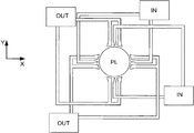
提案されている1つの解決策としては、液体供給システム(基板は、一般に投影システムの最終要素よりも大きな表面積を有する)を使用して、基板の局部上、かつ投影システムの最終要素と基板の間のみに液体を供給する液体供給システムが提案されている。そうするために提案された1つの方法が、PCT特許出願公開WO99/49504に開示されており、その全体を参照として本明細書に援用する。図2及び図3に示されているように、液体は、好ましくは最終要素に対する基板の相対移動の方向に沿って、少なくとも1つの入口INから基板上に供給され、投影システムの下を通過後、少なくとも1つの出口OUTから除去される。つまり、基板が要素の下を−X方向に走査されるとき、液体が要素の+X側で供給され−X側で回収される。図2は、液体が入口INを介して供給され、要素の向こう側の、低圧源に接続された出口OUTによって回収される構成を概略的に示している。図2では、最終要素に対する基板の相対移動の方向に沿って液体が供給されているが、必ずしもこうである必要はない。様々な向き、並びに最終要素の周りに様々な入口及び出口の数を配置させることが可能であり、一例が図3に示されている。図3では、入口と片側の出口とが4組、最終要素の周りに規則的パターンで設けられている。 One proposed solution is to use a liquid supply system (the substrate generally has a larger surface area than the final element of the projection system), on the local area of the substrate, and between the final element of the projection system and the substrate. There has been proposed a liquid supply system that supplies liquid only between the two. One method proposed to do so is disclosed in PCT patent application publication WO 99/49504, which is incorporated herein by reference in its entirety. As shown in FIGS. 2 and 3, the liquid is supplied onto the substrate from at least one inlet IN, preferably along the direction of relative movement of the substrate relative to the final element, and after passing under the projection system , Removed from at least one outlet OUT. That is, when the substrate is scanned under the element in the -X direction, liquid is supplied on the + X side of the element and collected on the -X side. FIG. 2 schematically shows a configuration in which liquid is supplied via an inlet IN and is recovered by an outlet OUT connected to a low pressure source across the element. In FIG. 2, the liquid is supplied along the direction of relative movement of the substrate relative to the final element, but this is not necessarily the case. Different orientations and different numbers of inlets and outlets can be arranged around the final element, an example is shown in FIG. In FIG. 3, four sets of inlets and outlets on one side are provided in a regular pattern around the final element.
露光前に、基板の位置合せ及びレベリングが行われる。これには複雑でかさの高い装置が必要である。浸漬液を供給するために使用される装置もかさばることがあり、それ故、浸漬装置、並びに位置合せ及びレベリング装置の配列は難しい。更に、露光を行うための屈折率が周りの領域の屈折率と異なることがあり、従って、位置合せ及びレベリングはより複雑になる。従って、浸漬装置内での正確な位置合せ及びレベリングは、難しく、問題である。更に、位置合せ及びレベリングが近くの「乾式」環境で行われる場合、基板上に残留液があると、誤測定を招くことがある。 Prior to exposure, the substrate is aligned and leveled. This requires complex and bulky equipment. The apparatus used to supply the immersion liquid can also be bulky and therefore the arrangement of the immersion apparatus and alignment and leveling apparatus is difficult. In addition, the refractive index for performing the exposure may be different from the refractive index of the surrounding area, thus making alignment and leveling more complicated. Thus, accurate alignment and leveling within the immersion apparatus is difficult and problematic. Furthermore, if alignment and leveling are performed in a nearby “dry” environment, residual liquid on the substrate can lead to erroneous measurements.
従って、例えば、浸漬リソグラフィ装置内での焦点合せが改善されたリソグラフィ投影装置を提供することが有利であろう。 Thus, for example, it would be advantageous to provide a lithographic projection apparatus with improved focusing within an immersion lithographic apparatus.
一態様によれば、放射ビームを供給するように構成された照明システムと、ビームの断面にパターンを付与するように構成されたパターン形成装置を保持するように構成された支持構造と、基板を保持するように構成された基板テーブルと、基板の標的部分上にパターン形成されたビームを投影するように構成された投影システムと、投影システムと基板テーブルの間の空間を少なくとも部分的に第1の液体で満たすように構成された第1の液体供給システムと、基板上の複数の点の位置をそれぞれ測定するように構成され、かつ第1の液体供給システムからは供給されない第2の液体中で測定が行われるように構成された測定システムとを備えるリソグラフィ装置が提供される。 According to one aspect, an illumination system configured to provide a radiation beam, a support structure configured to hold a patterning device configured to apply a pattern to a cross section of the beam, a substrate, A substrate table configured to hold; a projection system configured to project a patterned beam onto a target portion of the substrate; and a space between the projection system and the substrate table at least partially first. A first liquid supply system configured to be filled with a liquid and a second liquid configured to measure the positions of a plurality of points on the substrate and not supplied from the first liquid supply system. A lithographic apparatus comprising: a measurement system configured to perform measurements at:
基板の測定及び露光の両方が浸漬液を通して行われるので、光路長の変化によって誤差が生じない。更に、例えばレベリング及び位置合せ等の測定が液体を通して行われる場合は、基板上の残留液に伴う問題を避けることができる。 Since both the measurement of the substrate and the exposure are performed through the immersion liquid, no error occurs due to the change in the optical path length. Furthermore, problems associated with residual liquid on the substrate can be avoided if measurements such as leveling and alignment are performed through the liquid.
一実施例では、装置は、測定システムと基板テーブルの間の空間を少なくとも部分的に第2の液体で満たすように構成された第2の液体供給システムを含む。第1の液体供給システムによって供給される第1の液体と、第2の液体供給システムで供給される第2の液体とは同じ種類であってよい。そうすることで、液体間の屈折率の違いによる誤差の解消に役立つはずである。 In one example, the apparatus includes a second liquid supply system configured to at least partially fill a space between the measurement system and the substrate table with the second liquid. The first liquid supplied by the first liquid supply system and the second liquid supplied by the second liquid supply system may be the same type. Doing so should help eliminate errors due to differences in refractive index between liquids.
一実施例では、測定システムは、基板上の複数の点の高さ測定(つまり、Z方向における測定)及び/又は傾斜測定(つまり、Rx及び/又はRy方向における測定)を行うように構成されたレベル・センサを含む。例えば、基板上のある1点の高さを測定するには、ビームをある回折格子を介して投影させ、基板上のある1点で反射させ、次いで別の回折格子を介して投影させることができる。各回折格子の画像の重なりの程度が基板上のその点の高さを示す。従って、投影システムを使用して基板を露光する前に、基板上の複数の点の相対位置を、それぞれ液体を通してマッピングすることができる。 In one embodiment, the measurement system is configured to perform height measurements (ie, measurements in the Z direction) and / or tilt measurements (ie, measurements in the R x and / or R y directions) of multiple points on the substrate. Includes configured level sensor. For example, to measure the height of a point on the substrate, the beam can be projected through a diffraction grating, reflected at a point on the substrate, and then projected through another diffraction grating. it can. The degree of overlap of the images of each diffraction grating indicates the height of that point on the substrate. Thus, before exposing the substrate using the projection system, the relative positions of the points on the substrate can each be mapped through the liquid.
一実施例では、測定システムは、基板上の複数の位置合せマークの位置を測定(X、Y及び/又はRz方向における測定)するように構成された位置合せシステムを含む。浸漬液内での使用に特に適した位置合せセンサは、係属中のヨーロッパ特許出願第03255395.0号に記載されている。基板は、参照基準を持つことができ、測定システムはその参照基準の位置を測定する。一実施例では、基板テーブルの参照基準を基準として複数の位置合せマークそれぞれの位置を測定して、参照基準を基準とする位置合せマークのマップを作成することができる。一実施例では、参照基準は透過画像センサを含む。 In one embodiment, the measurement system includes an alignment system configured to measure the position of multiple alignment marks on the substrate (measurement in the X, Y and / or Rz directions). An alignment sensor that is particularly suitable for use in immersion liquid is described in pending European Patent Application No. 03255395.0. The substrate can have a reference standard, and the measurement system measures the position of the reference standard. In one embodiment, the position of each of the plurality of alignment marks can be measured based on the reference standard of the substrate table, and a map of alignment marks based on the reference standard can be created. In one embodiment, the reference standard includes a transmission image sensor.
一実施例によれば、露光部及び別に設けた測定部があり、露光部には投影システムが設けられ、測定部には測定システムが設けられ、基板テーブルは露光部と測定部の間で移動可能となっている。更に、複数の基板テーブルを設け、それぞれを露光部と測定部の間で移動可能とすることもできる。基板テーブルは、基板を支持するように設計されており、移動のための装置を組み込むか、或いはモータや機械式アーム等、装置の別の部分によって移動させることもできる。 According to one embodiment, there is an exposure unit and a separate measurement unit, the exposure unit is provided with a projection system, the measurement unit is provided with a measurement system, and the substrate table is moved between the exposure unit and the measurement unit. It is possible. Furthermore, a plurality of substrate tables can be provided, and each can be moved between the exposure unit and the measurement unit. The substrate table is designed to support the substrate and may incorporate a device for movement or may be moved by another part of the device, such as a motor or mechanical arm.
一実施例では、投影部及び測定部は別々である、つまり、1つの基板は同時に露光部と測定部に存在することはできない。従って、1つの基板テーブルをマッピング中に、第2の基板テーブルを露光することができる。従って、基板のスループットが上がり、装置はより効率的になり、所有コストが改善される。 In one embodiment, the projection unit and the measurement unit are separate, that is, one substrate cannot exist in the exposure unit and the measurement unit at the same time. Thus, the second substrate table can be exposed while mapping one substrate table. Thus, the throughput of the substrate is increased, the device is more efficient and the cost of ownership is improved.
一実施例では、位置合せシステムは、2つの互いに垂直な直線方向の変位、及びその2つの垂直方向によって規定される平面内の回転を測定する。 In one example, the alignment system measures two mutually perpendicular linear displacements and a rotation in a plane defined by the two perpendicular directions.
一実施例では、第1の液体供給システムの液体源と第2の液体供給システムの液体源とが同じである。こうすることにより、第1及び第2の液体供給システムの両方に同じ浸漬液を使用し、露光部及び測定部の両方に新鮮な浸漬液を供給するようにすることができる。従って、浸漬液の質又は特性が変わっても、測定部及び露光部の両方の全体にそれを行き渡らせることができる。従って、測定部と露光部の間の光路長の相対誤差を最小限に抑えることができる。一実施例では、第1及び第2の液体供給システムは接続されてもよい。例えば、測定部用の液体供給システムの出口からの浸漬液を、露光部用の液体供給システムの入口へ供給することができる。 In one embodiment, the liquid source of the first liquid supply system and the liquid source of the second liquid supply system are the same. By doing so, it is possible to use the same immersion liquid in both the first and second liquid supply systems and supply fresh immersion liquid to both the exposure unit and the measurement unit. Therefore, even if the quality or characteristics of the immersion liquid changes, it can be distributed throughout both the measurement part and the exposure part. Therefore, the relative error of the optical path length between the measurement unit and the exposure unit can be minimized. In one embodiment, the first and second liquid supply systems may be connected. For example, the immersion liquid from the outlet of the liquid supply system for the measurement unit can be supplied to the inlet of the liquid supply system for the exposure unit.
一実施例によれば、第1の液体供給システム及び第2の液体供給システムが別々に設けられる。これらは、同じ液体源を持たず、接続もされていない。測定には特定の液体が有利であり得るが、露光部では他の液体を使用することが適切であり得る。 According to one embodiment, the first liquid supply system and the second liquid supply system are provided separately. They do not have the same liquid source and are not connected. While certain liquids may be advantageous for measurement, it may be appropriate to use other liquids in the exposure section.
一実施例では、第1の液体供給システムは、投影システムと基板テーブル間の空間の境界の少なくとも一部に沿って延びる封止部材を含む。更に、第2の液体供給システムは、測定システムと基板テーブル間の空間の境界の少なくとも一部に沿って延びる封止部材を含む。従って、液体は、封止部材によって局部に封じ込められ、浸漬液による装置への損傷を最小限に抑えることができる。 In one embodiment, the first liquid supply system includes a sealing member that extends along at least a portion of the boundary of the space between the projection system and the substrate table. In addition, the second liquid supply system includes a sealing member that extends along at least a portion of the boundary of the space between the measurement system and the substrate table. Accordingly, the liquid is confined locally by the sealing member, and damage to the apparatus by the immersion liquid can be minimized.
一実施例では、液体供給システムは、封止部材と基板表面の間を封止するように構成されたシールを含む。このシールは、封止部材と基板テーブルの間に非接触シールを形成することができ、それにより、例えば、測定中又は走査露光中それぞれに、基板が、例えば投影システム及び/又は測定システムの下を移動するときに、投影システム及び/又は測定システムと基板テーブルとの間の空間に液体を封じ込める。シールは、気体シールでも、流体静力学的シールでも、流体動力学的シールでもよい。 In one embodiment, the liquid supply system includes a seal configured to seal between the sealing member and the substrate surface. This seal may form a non-contact seal between the sealing member and the substrate table, so that the substrate is, for example, under the projection system and / or under the measurement system, for example during measurement or during scanning exposure, respectively. When moving, the liquid is contained in the space between the projection system and / or measurement system and the substrate table. The seal may be a gas seal, a hydrostatic seal, or a hydrodynamic seal.
封止部材は、円形であれ、方形であれ、又は他の形であれ、閉ループの形をとって空間の周りに設けられてもよいし、不完全なもの、例えばU字形を形成するものでも、単に空間の片側に沿って延びる形のものでさえもよい。封止部材が不完全な場合でも、それは、基板が投影システム及び/又は測定システムの下を移動するときに液体を封じ込める位置になければならない。 The sealing member, whether round, square or otherwise, may be provided around the space in the form of a closed loop, or may be imperfect, for example forming a U shape Or simply extending along one side of the space. Even if the sealing member is imperfect, it must be in a position to contain liquid as the substrate moves under the projection system and / or measurement system.
一実施例では、封止部材とシールの内側の基板表面との間隙は小さいので、毛管現象によって液体が間隙に引き込まれる。気体シールからのガスも、空間に入るのが防止される。封止部材の下に液体を引き込む毛管力と、ガス流の押し出しとの均衡がとられ、特に安定したシールが形成される。 In one embodiment, the gap between the sealing member and the substrate surface inside the seal is small, so that liquid is drawn into the gap by capillary action. Gas from the gas seal is also prevented from entering the space. The capillary force that draws liquid under the sealing member and the extrusion of the gas flow are balanced, and a particularly stable seal is formed.
一態様によれば、放射ビームを供給するように構成された照明システムと、ビームの断面にパターンを付与するように構成されたパターン形成装置を保持するように構成された支持構造と、基板を保持するように構成された基板テーブルと、基板の標的部分上にパターン形成されたビームを投影するように構成された投影システムと、測定ビームを使用して基板上の複数の点の位置をそれぞれ測定するように構成された測定システムと、投影システムと基板テーブルの間の空間、並びに測定システムと基板テーブルの間の空間を少なくとも部分的に液体で満たすように構成された液体供給システムとを備え、測定システムが、基板テーブルが投影ビーム及び測定ビームの経路内に同時に存在できないように構成されたリソグラフィ装置が提供される。 According to one aspect, an illumination system configured to provide a radiation beam, a support structure configured to hold a patterning device configured to apply a pattern to a cross section of the beam, a substrate, A substrate table configured to hold; a projection system configured to project a patterned beam onto a target portion of the substrate; and a plurality of points on the substrate using a measurement beam, respectively A measurement system configured to measure, and a liquid supply system configured to at least partially fill the space between the projection system and the substrate table and the space between the measurement system and the substrate table. A lithographic apparatus is provided wherein the measurement system is configured such that the substrate table cannot be simultaneously in the path of the projection beam and the measurement beam It is.
更なる態様によれば、測定システムから投影される測定ビームを使用して、基板上の複数の点の位置をそれぞれ測定する工程であって、測定が液体中で行われるが、基板と投影システムの間に供給される液体中では行われない工程と、基板と投影システムの間に供給される液体を通して、パターン形成された放射ビームを基板の標的部分上に投影する工程とを含む、デバイス製造方法が提供される。 According to a further aspect, measuring each of the positions of a plurality of points on the substrate using a measurement beam projected from the measurement system, wherein the measurement is performed in a liquid, the substrate and the projection system Manufacturing a device comprising: steps not performed in a liquid supplied between, and projecting a patterned beam of radiation onto a target portion of the substrate through the liquid supplied between the substrate and the projection system A method is provided.
更なる態様によれば、測定システムから投影される測定ビームを使用して、測定システムと基板の間に供給される液体中で基板上の複数の点の位置をそれぞれ測定する工程と、液体を通して、パターン形成された放射ビームを基板の標的部分上に投影する工程とを含み、パターン形成されたビーム及び測定ビームが、パターン形成されたビーム及び測定ビームの経路内に基板が同時に存在しないように構成されるデバイス製造方法が提供される。 According to a further aspect, using the measurement beam projected from the measurement system, respectively measuring the positions of a plurality of points on the substrate in the liquid supplied between the measurement system and the substrate, and through the liquid Projecting a patterned beam of radiation onto a target portion of a substrate so that the patterned beam and the measurement beam are not simultaneously present in the path of the patterned beam and the measurement beam. A structured device manufacturing method is provided.
デバイスは、先に述べたいくつかの方法に従って製造することができる。 The device can be manufactured according to several methods described above.
さらなる態様によれば、放射ビームを供給するように構成された照明システムと、ビームの断面にパターンを付与するように構成されたパターン形成装置を保持するように構成された支持構造と、基板を保持するように構成された基板テーブルと、基板の標的部分上にパターン形成されたビームを投影するように構成された投影システムと、投影システムの最終要素と基板テーブルの間の空間を、少なくとも部分的に第1の液体で満たすように構成された第1の液体供給システムと、基板上の複数の点の位置をそれぞれ測定するように構成され、かつ第1の液体供給システムからは供給されない第2の液体中で測定が行われるように構成された測定システムとを備えるリソグラフィ装置が提供される。 According to a further aspect, an illumination system configured to provide a radiation beam, a support structure configured to hold a patterning device configured to apply a pattern to a cross section of the beam, a substrate, At least a portion of a substrate table configured to hold, a projection system configured to project a patterned beam onto a target portion of the substrate, and a space between a final element of the projection system and the substrate table A first liquid supply system configured to be filled with the first liquid, and a first liquid supply system configured to measure positions of a plurality of points on the substrate, respectively, and not supplied from the first liquid supply system A lithographic apparatus is provided comprising a measurement system configured to perform measurements in two liquids.
本明細書では、IC製造におけるリソグラフィ装置の使用について特に述べるが、本明細書に記述するリソグラフィ装置は、磁気ドメイン・メモリ用の集積光学系、ガイダンス及び検出パターン、並びに、液晶表示装置(LCD)、薄膜磁気ヘッド等の製造等、他の応用例も含むことができることを理解されたい。このような代替の応用例に関して、本明細書で「ウェハ」又は「ダイ」という用語が使われている場合は、より一般的な用語である「基板」又は「標的部分」とそれぞれ同義語とみなすことができることは、当業者には理解されよう。本明細書に記載する基板は、例えば、トラック(通常、基板にレジスト層を施し、露光されたレジストを現像するツール)、測定ツール又は検査ツールにおいて、露光の前又は後に処理することができる。応用可能であれば、本明細書の開示は、このような他の基板処理ツールに使用することができる。更に、基板は、例えば、多層ICを作成するために2回以上処理することができる。従って、本明細書で使用する「基板」という用語は、処理済みの複数の層を既に含む基板であるとも言える。 Although this specification specifically describes the use of a lithographic apparatus in IC manufacturing, the lithographic apparatus described herein includes integrated optics for magnetic domain memory, guidance and detection patterns, and a liquid crystal display (LCD). It should be understood that other applications such as the manufacture of thin film magnetic heads and the like can also be included. For such alternative applications, where the term “wafer” or “die” is used herein, the more general terms “substrate” or “target portion” are synonymous with Those skilled in the art will appreciate that it can be considered. The substrates described herein can be processed before or after exposure, for example, in a track (usually a tool that applies a resist layer to the substrate and develops the exposed resist), measurement tool, or inspection tool. Where applicable, the disclosure herein can be used with such other substrate processing tools. Further, the substrate can be processed more than once, for example, to create a multilayer IC. Thus, as used herein, the term “substrate” can be said to be a substrate that already contains multiple processed layers.
本明細書で使用する「放射線」及び「ビーム」という用語は、紫外(UV)線(例えば、波長365、248、193、157又は126nmを有するもの)等、あらゆる種類の電磁放射線を包含する。 As used herein, the terms “radiation” and “beam” encompass all types of electromagnetic radiation, such as ultraviolet (UV) radiation (eg, having a wavelength of 365, 248, 193, 157 or 126 nm).
本明細書で使用する「パターン形成装置」という用語は、投影ビームの断面にパターンを付与して、基板の標的部分にパターンを形成するため等に使用できるどんな装置も意味するとして広く解釈されたい。投影ビームに付与されるパターンは、基板の標的部分における所望のパターンに厳密には対応しないことがあることに留意されたい。一般に、投影ビームに付与されるパターンは、集積回路等、標的部分内に形成されるデバイス内の特定の機能層に対応する。 As used herein, the term “patterning device” should be interpreted broadly to mean any device that can be used to apply a pattern to a cross section of a projection beam to form a pattern on a target portion of a substrate, etc. . Note that the pattern imparted to the projection beam may not exactly correspond to the desired pattern at the target portion of the substrate. In general, the pattern imparted to the projection beam will correspond to a particular functional layer in a device being formed in the target portion, such as an integrated circuit.
パターン形成装置は、透過性でも反射性でもよい。パターン形成装置の実施例には、マスク、プログラム可能ミラー・アレイ、及びプログラム可能LCDパネルが含まれる。マスクはリソグラフィ分野では公知であり、マスクの種類には、バイナリ・マスク、交互位相シフト・マスク及び減衰位相シフト・マスク、並びに様々なハイブリッド・マスクが含まれる。プログラム可能ミラー・アレイの実施例では、異なる方向から入る放射線ビームを反射するようにそれぞれ傾斜させることができる小さなミラーから成るマトリックス配列を使用し、このようにして反射ビームはパターン形成される。パターン形成装置の各実施例では、支持構造は、例えば必要に応じて固定又は移動可能で、パターン形成装置を、例えば、投影システムに対して所望の位置に存在させるようにできる、フレーム又はテーブルとすることができる。本明細書で「レチクル」又は「マスク」という用語が使われている場合は、より一般的な用語である「パターン形成装置」と同義語であるとみなすことができる。 The patterning device may be transmissive or reflective. Examples of patterning devices include masks, programmable mirror arrays, and programmable LCD panels. Masks are well known in the lithography art, and mask types include binary masks, alternating phase shift masks and attenuated phase shift masks, and various hybrid masks. The programmable mirror array embodiment uses a matrix array of small mirrors, each of which can be tilted to reflect a radiation beam coming from different directions, and the reflected beam is thus patterned. In each embodiment of the patterning device, the support structure may be fixed or movable, for example, as required, and the frame or table, for example, to allow the patterning device to be in a desired position, for example with respect to the projection system. can do. Any use of the terms “reticle” or “mask” herein may be considered synonymous with the more general term “patterning device”.
本明細書で使用する「投影システム」という用語は、例えば、使用する露光放射線、或いは浸漬液の使用又は真空の使用等の他のファクタに適した屈折光学系、反射光学系、及び反射屈折光学系等、様々な種類の投影システムを包含するものとして広く解釈されるべきである。本明細書で「レンズ」という用語が使われている場合は、より一般的な用語である「投影システム」と同義語であるとみなすことができる。 As used herein, the term “projection system” refers to refractive optics, reflective optics, and catadioptric optics suitable for other factors such as, for example, the exposure radiation used or the use of immersion liquid or the use of vacuum. It should be broadly interpreted as encompassing various types of projection systems, such as systems. Any use of the term “lens” herein may be considered as synonymous with the more general term “projection system”.
照明システムも、放射線の投影ビームを案内し、整形し、又は制御するための屈折光学系、反射光学系、及び反射屈折光学系の構成要素等、様々な種類の光学系構成要素を包含し、このような構成要素もまた、以下に、一括して又は単独で「レンズ」と呼ぶことができる。 The illumination system also includes various types of optical components such as refractive optics, reflective optics, and catadioptric components for guiding, shaping, or controlling a projection beam of radiation, Such components may also be referred to collectively below or collectively as “lenses”.
リソグラフィ装置は、2つ(2ステージ)以上の基板テーブル(及び/又は2枚以上のマスク・テーブル)を有する種類のものでよい。このような「複数ステージ」の機械装置では、並行して追加のテーブルも使用することができる。或いは1つ又は複数のテーブル上で予備工程を実行し、1つ又は複数の他のテーブルを露光のために使用することができる。例えば、1つの基板テーブルでレベリング測定を行い、別のステージ上で露光を行うことができる。 The lithographic apparatus may be of a type having two (dual stage) or more substrate tables (and / or two or more mask tables). In such a “multi-stage” machine, additional tables can be used in parallel. Alternatively, a preliminary process can be performed on one or more tables and one or more other tables can be used for exposure. For example, leveling measurement can be performed on one substrate table and exposure can be performed on another stage.
以下に、ほんの一例として、添付の概略図面を参照して、本発明の実施例について述べる。図面において、対応する参照番号は対応する部分を示す。 In the following, embodiments of the present invention will be described by way of example only with reference to the accompanying schematic drawings. Corresponding reference numerals indicate corresponding parts in the drawings.
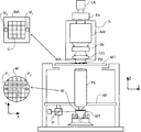
図1は、本発明の特定の実施例によるリソグラフィ装置の概略図である。この装置は、放射線(例えば、UV放射線)の投影ビームPBを供給する照明システム(照明器)ILと、パターン形成装置(例えば、マスク)MAを支持し、アイテムPLに対してパターン形成装置を正確に位置決めする第1の位置決め装置PMに接続された第1の支持構造(例えば、マスク・テーブル)MTと、基板(例えば、レジスト被膜ウェハ)Wを保持し、アイテムPLに対して基板を正確に位置決めする第2の位置決め装置PWに接続された基板テーブル(例えば、ウェハ・テーブル)WTと、パターン形成装置MAによって投影ビームPBに付与されたパターンを、基板Wの標的部分C(例えば、1つ又は複数のダイを含む)上に結像させる投影システム(例えば、屈折投影レンズ)PLとを含む。 FIG. 1 schematically depicts a lithographic apparatus according to a particular embodiment of the invention. This apparatus supports an illumination system (illuminator) IL that supplies a projection beam PB of radiation (eg, UV radiation) and a patterning device (eg, mask) MA, and is accurate for the item PL. The first support structure (for example, mask table) MT connected to the first positioning device PM for positioning on the substrate and the substrate (for example, resist-coated wafer) W are held, and the substrate is accurately positioned with respect to the item PL. A substrate table (for example, a wafer table) WT connected to a second positioning device PW for positioning, and a pattern applied to the projection beam PB by the pattern forming device MA are used as a target portion C (for example, one). Or a projection system (eg, a refractive projection lens) PL that forms an image on a plurality of dies).
図に示すように、装置は透過型のものである(例えば、透過マスクを使用したもの)。或いは、装置は屈折型のものでもよい(例えば、先に述べた型のプログラム可能ミラー・アレイを使用したもの)。 As shown, the apparatus is of a transmissive type (eg, using a transmissive mask). Alternatively, the device may be of the refractive type (eg, using a programmable mirror array of the type described above).
照明器ILは、放射線源SOから放射ビームを受ける。放射線源及びリソグラフィ装置は、例えば、放射線源がエキシマ・レーザである場合、別々の要素とすることができる。この場合、放射線源は、リソグラフィ装置の部分を形成するとはみなされず、放射ビームは、例えば、適切な誘導ミラー及び/又はビーム・エキスパンダを含むビーム供給システムBDによって、放射線源SOから照明器ILへ送られる。その他の場合、例えば、放射線源が水銀ランプの場合、放射線源は装置の一体部分とすることができる。放射線源SO及び照明器IL、並びにビーム供給システムBDが必要な場合はそれも併せて、放射システムと呼ぶことができる。 The illuminator IL receives a radiation beam from a radiation source SO. The radiation source and the lithographic apparatus can be separate elements, for example when the radiation source is an excimer laser. In this case, the radiation source is not considered to form part of the lithographic apparatus, and the radiation beam is emitted from the radiation source SO to the illuminator IL, for example by means of a beam delivery system BD including suitable guide mirrors and / or beam expanders. Sent to. In other cases, for example, where the radiation source is a mercury lamp, the radiation source may be an integral part of the apparatus. If a radiation source SO and an illuminator IL and a beam delivery system BD are required, they can also be referred to as a radiation system.
照明器ILは、ビームの角輝度分布を調整する調整手段AMを含むことができる。一般に、証明器の瞳平面における輝度分布の、少なくとも、半径方向の外側及び/又は内側の範囲(通常、それぞれσ−アウター及びσ−インナーと呼ばれる)を調整することができる。更に、照明器ILは、一般に積分器INやコンデンサCO等、様々な他の構成要素を含む。照明器は、投影ビームPBと呼ばれ、その断面において所望の均一性及び輝度分布を有する調節済みの放射ビームを提供する。 The illuminator IL may include adjusting means AM for adjusting the angular luminance distribution of the beam. In general, at least the radially outer and / or inner extent (usually referred to as σ-outer and σ-inner, respectively) of the luminance distribution in the pupil plane of the prover can be adjusted. In addition, the illuminator IL typically includes various other components such as an integrator IN and a capacitor CO. The illuminator is referred to as the projection beam PB and provides a conditioned radiation beam having the desired uniformity and brightness distribution in its cross section.
投影ビームPBは、マスク・テーブルMT上に保持されたマスクMAに入射する。投影ビームPBは、マスクMAを横断後、投影システムPLを通過し、それにより基板Wの標的部分C上にビームが収束される。基板テーブルWTは、第2の位置決め装置PW及び位置センサIF(例えば、干渉計装置)によって、例えば互いに異なる標的部分CがビームPBの経路内に位置するように、正確に移動することができる。同様に、第1の位置決め装置PM及び別の位置センサ(図1には明確に示していない)を、例えばマスク・ライブラリからの機械的検索の後に又は走査中に使って、マスクMAをビームPBの経路に対して正確な位置に配置させることができる。一般に、対象テーブルMT及びWTの移動は、位置決め装置PM及びPWの一部を形成する、長いストロークのモジュール(大雑把な位置決め)及び短いストロークのモジュール(微細な位置決め)によって実現される。しかし、ステッパの場合(スキャナとは対照的に)、マスク・テーブルMTは、短いストロークのアクチュエータのみに接続又は固定されることがある。マスクMA及び基板Wは、マスク位置合せマークM1及びM2、並びに基板位置合せマークP1及びP2を使用して位置合せすることができる。 The projection beam PB is incident on the mask MA, which is held on the mask table MT. The projection beam PB passes through the projection system PL after traversing the mask MA, whereby the beam is focused on the target portion C of the substrate W. The substrate table WT can be accurately moved by the second positioning device PW and the position sensor IF (eg interferometer device), for example so that different target portions C are located in the path of the beam PB. Similarly, the first positioner PM and another position sensor (not explicitly shown in FIG. 1) are used, for example after mechanical retrieval from the mask library or during a scan, to use the mask MA as the beam PB. It can be arranged at an accurate position with respect to the path. In general, the movement of the target tables MT and WT is realized by a long stroke module (rough positioning) and a short stroke module (fine positioning) which form part of the positioning devices PM and PW. However, in the case of a stepper (as opposed to a scanner) the mask table MT may be connected or fixed to only a short stroke actuator. Mask MA and substrate W may be aligned using mask alignment marks M 1 and M 2 and substrate alignment marks P 1 and P 2 .
図に示した装置は、次の好ましいモードで使用することができる。 The apparatus shown in the figure can be used in the following preferred modes.
1.ステップ・モードでは、マスク・テーブルMT及び基板テーブルWTが、基本的に静止状態に保たれ、投影ビームに付与されたパターン全体が、ある標的部分C上に一度に投影される(つまり、単一静的露光)。次いで、別の標的部分Cを露光することができるように、基板テーブルWTをX及び/又はY方向にシフトさせる。ステップ・モードでは、露光領域の最大のサイズによって、単一静的露光で結像される標的部分Cの大きさが制限される。 1. In step mode, the mask table MT and the substrate table WT are essentially kept stationary, and the entire pattern imparted to the projection beam is projected onto a target portion C at a time (ie, a single Static exposure). The substrate table WT is then shifted in the X and / or Y direction so that another target portion C can be exposed. In step mode, the maximum size of the exposure area limits the size of the target portion C imaged in a single static exposure.
2.スキャン・モードでは、マスク・テーブルMT及び基板テーブルWTが、同期的に走査され、投影ビームに付与されたパターンが、ある標的部分C上に投影される(つまり、単一動的露光)。マスク・テーブルMTに対する基板テーブルWTの速度及び方向は、投影システムPLの拡大(縮小)特性及び像反転特性によって決まる。スキャン・モードでは、単一動的露光における標的部分の幅(非走査方向の幅)は、露光領域の最大のサイズによって制限されるが、標的部分の長さ(走査方向の長さ)は、走査動作の長さによって決まる。 2. In scan mode, the mask table MT and the substrate table WT are scanned synchronously and a pattern imparted to the projection beam is projected onto a target portion C (ie, a single dynamic exposure). The speed and direction of the substrate table WT relative to the mask table MT depends on the enlargement (reduction) characteristics and image reversal characteristics of the projection system PL. In scan mode, the width of the target portion in a single dynamic exposure (width in the non-scan direction) is limited by the maximum size of the exposure area, but the length of the target portion (length in the scan direction) It depends on the length of the movement.
3.別のモードでは、マスク・テーブルMTが、プログラム可能パターン形成装置を保持して基本的に静止状態に保たれ、基板テーブルWTが、移動又は走査され、投影ビームに付与されたパターンが、ある標的部分C上に投影される。このモードでは、一般に、パルス放射線源が使用され、プログラム可能パターン形成装置は、基板テーブルWTの移動が済む度に、又は走査中の連続的放射パルスの合間に必要に応じて更新される。この操作モードは、先に述べたような種類のプログラム可能ミラー・アレイ等、プログラム可能パターン形成装置を利用する、マスクなしのリソグラフィに容易に適用できる。 3. In another mode, the mask table MT is held essentially stationary with a programmable patterning device, the substrate table WT is moved or scanned, and the pattern imparted to the projection beam is on a certain target Projected onto part C. In this mode, a pulsed radiation source is generally used and the programmable patterning device is updated as needed after each movement of the substrate table WT or between successive radiation pulses during the scan. This mode of operation can be readily applied to maskless lithography that utilizes programmable patterning device, such as a programmable mirror array of a type as previously described.
上記の使用モードの組合せ及び/又は変更、或いは全く異なる使用モードも利用することができる。 Combinations and / or modifications of the above described modes of use or entirely different modes of use may also be employed.
浸漬用リソグラフィ液供給システムには、投影システムの要素と基板テーブルの間の空間の境界の少なくとも一部に沿って延びる封止部材を設けることができる。封止部材は、X、Y又はZ方向に(但し、Z方向は光軸の方向である)ある程度相対移動することがあるが、XY平面内の投影システムに対して実質的に静止している。シールは、封止部材と基板表面の間に形成される。一実施例では、シールは、気体シール等の無接触シールである。このようなシステムは、例えば、その全体を参照として本明細書に援用される米国特許出願第10/705,783号に開示されている。 The immersion lithographic liquid supply system may be provided with a sealing member that extends along at least a portion of the boundary of the space between the elements of the projection system and the substrate table. The sealing member may move to some extent in the X, Y or Z direction (where the Z direction is the direction of the optical axis) but is substantially stationary relative to the projection system in the XY plane. . The seal is formed between the sealing member and the substrate surface. In one embodiment, the seal is a contactless seal such as a gas seal. Such a system is disclosed, for example, in US patent application Ser. No. 10 / 705,783, which is hereby incorporated by reference in its entirety.
光路長は、光ビームが通過する媒体の屈折率によって変わる。従って、投影ビームが浸漬液を通して投影される場合、光路長は、同様のビームが気体を透過する場合とは異なる。位置合せ及び/又はレベリングの測定が、測定ビームを使用して乾式環境で行われ、露光が浸漬液を通して行われる場合、光路長の違いによって位置合せ誤差が生じ得る。光路長の違いが補償されたとしても、基板が2回目或いはそれ以降の回に位置合せ及び/又はレベリングされる時に基板上に残留浸漬液があると、更に誤差が生じ得る。 The optical path length depends on the refractive index of the medium through which the light beam passes. Thus, when the projection beam is projected through the immersion liquid, the optical path length is different from that of a similar beam passing through the gas. When alignment and / or leveling measurements are performed in a dry environment using a measurement beam and exposure is performed through immersion liquid, alignment path errors can result from differences in optical path lengths. Even if the difference in optical path length is compensated for, there may be further errors if there is residual immersion liquid on the substrate when the substrate is aligned and / or leveled a second time or later.
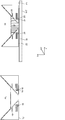
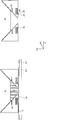
従って、一実施例では、図5に示すように、測定システム30と基板テーブルWTの間の空間に液体(例えば、水)を供給して液体貯蔵槽20を形成するように、液体供給口28が設けられている。この実施例では、貯蔵槽20は、測定システム30のイメージ・フィールドの周りに基板に対して無接触シールを形成することによって、液体を封じ込め、基板表面と投影システム30の最終要素との間の空間を満たしている。測定システム30の最終要素の下でそれを取り囲んで位置する封止部材22は、貯蔵槽20と境を接し、液体供給口28を含む。封止部材22は、測定システムの最終要素の少し上に延び、上端部で測定システム又はその最終要素の、例えば丸みを帯びた形状にぴったりと一致する内周を有している。測定システムの下の空間及び封止部材22内に液体が供給され、液体の液面が測定システム30の最終要素より高くなり、液体緩衝域が提供される。
Accordingly, in one embodiment, as shown in FIG. 5, the
封止部材22の底部と基板Wの表面の間に形成された気体シール26によって、液体が槽内に封じ込まれる。気体シールは、例えば、空気又は人工空気、好ましくはN2又は別の不活性ガス等の気体によって形成されており、こうした気体は、封止部材22と基板Wの間に入口25から加圧供給され第1の出口24から回収される。気体入口25にかかる過剰圧力、第1の出口24の真空度、及び間隙の幾何形状は、液体を封じ込めるための内側に向かう高速空気流が生じるように構成される。
The liquid is sealed in the tank by a
或いは、気体シール16の代わりに静圧軸受又は動圧シールを使用することもできる。静圧軸受については、ヨーロッパ特許出願第03254078.3号に記載されている。ヨーロッパ特許出願公開第1477856号には、少なくともZ方向に作動可能な封止部材が開示されており、このような封止部材は本発明にも適している。
Alternatively, a hydrostatic bearing or a dynamic pressure seal can be used instead of the
槽20を液体で満たした後、測定部で位置合せ及び/又はレベル測定を行うことができる。基板テーブルには、基準とも呼ばれることがある参照基準F1が設けられている。参照基準F1は、エッチングにより標準位置合せマークに対応するパターンで穴を開けたプレートを含むことができ、その下には、透過画像センサとしても知られる、放射線に反応する放射線センサがある。測定部では、測定システム30内の位置合せシステムを使用し、基板テーブルWTを移動させて参照基準F1を検出し、次いで基板W上の複数の位置合せマークを検出し、そうすることで基板の複数の位置合せマークの位置(本明細書ではX、Y及び/又はRz方向を意味する)を探し出すことができる。一実施例では、位置合せマークの位置は、参照基準F1を基準にして測定され決められる。
After filling the tank 20 with the liquid, alignment and / or level measurement can be performed in the measurement unit. The substrate table is provided with a reference standard F1, which may also be called a standard. The reference standard F1 can include a plate that has been perforated with a pattern corresponding to a standard alignment mark by etching, below which is a radiation sensor that reacts to radiation, also known as a transmission image sensor. In the measurement section, the alignment system in the
次いで、測定部で基板のレベル測定が行われる。基板のレベルを測定するために、基板Wから反射される前に第1の回折格子を横切る、レベリング・ビーム(測定システム30から投影される)を使用することができる。次いで、第2の回折格子を、基板Wから反射された後のレベリング・ビームの経路に配置する。レベル測定センサによって、第1及び第2の回折格子の画像が一致する程度が測定される。その程度は、基板Wの高さ(本明細書ではZ方向を意味する)及び/又は傾斜(本明細書ではRx及び/又はRy方向を意味する)によって決まる。基板のレベル測定の更なる説明については、ヨーロッパ特許出願公開第1304597号を参照されたい。従って、基板の位置合せ及び基板のレベル測定からのデータを使用することによって、基板のマップを生成することができる。 Next, the level of the substrate is measured in the measurement unit. To measure the level of the substrate, a leveling beam (projected from the measurement system 30) that traverses the first diffraction grating before being reflected from the substrate W can be used. The second diffraction grating is then placed in the path of the leveling beam after being reflected from the substrate W. The level measurement sensor measures the degree to which the images of the first and second diffraction gratings match. The degree depends on the height of the substrate W (referred to herein as the Z direction) and / or tilt (referred to herein as the Rx and / or Ry directions). For a further description of substrate level measurement, reference is made to EP 1304597. Thus, by using data from substrate alignment and substrate level measurements, a map of the substrate can be generated.
基板Wの測定終了後、例えば気体入口の圧力を低下させ、液体を真空システムによって吸い出すことによって液体槽20を空にすることができる。或いは、例えば図2、図3及び図4に示すケースでは、入口INから基板上への液体の流れを断ち、液体が出口OUTから吸い出されるようにすることによっても空にすることができる。 After the measurement of the substrate W is completed, the liquid tank 20 can be emptied, for example, by reducing the pressure at the gas inlet and sucking out the liquid by the vacuum system. Alternatively, for example, in the cases shown in FIGS. 2, 3 and 4, the liquid can be emptied by cutting off the flow of liquid from the inlet IN onto the substrate and sucking out the liquid from the outlet OUT.
次いで、図6に示すように、基板テーブルWTを、別に設けた露光部へ移動させる。露光部は、測定部と同様な液体供給口18、及び槽10を収める封止部材12を有する。封止部材12の底部では、必ずしもそうである必要はないが、内周がイメージ・フィールドの、例えば方形の形状にぴったりと一致している。入口15及び出口14を有する気体シールも存在する。基板テーブルが露光部に移動した後、液体供給口18を介して液体槽10が満たされる。露光部での基板テーブルWTの正確な位置を確認するために、マスクMA上の位置合せマークの空間像を介して、参照基準F1が立体的に走査される。参照基準がベスト・フォーカス平面内において、マスクのマークの画像と位置が合うと最大値信号が返される。従って、測定部で生成された基板Wのマップを使用することによって、基板W上の複数の点のそれぞれの位置(本明細書では位置、高さ及び/又は傾斜)が分かる。基板テーブルWTの移動を追跡するために、基板テーブルWTの1つ又は複数の側面に向けて投影される干渉計ビーム等、適切な位置測定装置を使用することができる。基板テーブルの特定の点を投影システムPLの焦点に置き、基板Wの標的部分Cを露光することができる。
Next, as shown in FIG. 6, the substrate table WT is moved to a separately provided exposure unit. The exposure unit includes a
次いで、槽10と同様にして槽20から液体が除去される。次いで、さらなる処理のために基板を取りはずし、新しい基板を基板テーブルWT上に配置することができる。新しい基板を有する基板テーブルを測定部へ戻し、プロセスを繰り返すことができる。 Next, the liquid is removed from the tank 20 in the same manner as the tank 10. The substrate can then be removed for further processing and a new substrate can be placed on the substrate table WT. The substrate table with the new substrate can be returned to the measurement section and the process can be repeated.
基板テーブルWTの正確な位置の確認のために、先に述べた透過画像センサの位置を液体を通して、又は液体を通さずに感知して補正を加えることができる。 In order to confirm the exact position of the substrate table WT, the position of the transmission image sensor described above can be sensed through the liquid or not, and correction can be applied.
一実施例では、それぞれが参照基準を有する少なくとも2つの基板テーブルがあり、一方の基板テーブルが測定部に存在する間、他方は露光部に存在する。これらの基板テーブルは、露光部と測定部の間を移動可能である。 In one embodiment, there are at least two substrate tables, each having a reference standard, while one substrate table is present in the measurement part and the other is present in the exposure part. These substrate tables are movable between the exposure unit and the measurement unit.
参照基準マークF1及び投影システムを使用して基板を位置合せする代わりに、光軸外測定を使用することができる。投影システムPL近傍の別のシステムを使用して、参照基準マークF1に位置合せすることができる。或いは、異なる参照基準及び異なるシステム、例えば、投影システムの投影軸に垂直な軸を有するものを使用することもできる。このような光軸外測定については、更にヨーロッパ特許出願公開第0906590号に記載されている。 Instead of aligning the substrate using the reference fiducial mark F1 and the projection system, off-axis measurements can be used. Another system near the projection system PL can be used to align with the reference fiducial mark F1. Alternatively, different reference standards and different systems can be used, for example those having an axis perpendicular to the projection axis of the projection system. Such off-axis measurement is further described in European Patent Application No. 0906590.
2つの液体供給口18及び28は、別々に設けられていても、接続されていてもよく、例えば液体源が同じでもよい。一方の槽の出口からの液体を、他方の槽の液体供給口の液体源とすることができる。
The two
基板テーブルが投影システムの上にある場合(つまり、投影システムが図1と上下逆である場合)、槽10及び20内の液体を、必ずしも完全に除去する必要はなく、必要に応じて補充することができる。 When the substrate table is above the projection system (ie, when the projection system is upside down from FIG. 1), the liquid in tanks 10 and 20 does not necessarily need to be completely removed and refilled as needed. be able to.
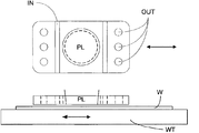
局部的液体供給システムを有する浸漬リソグラフィの更なる解決手段が、図4に示されている。液体は、投影システムPLの各側にある2本の溝状入口INから供給され、入口INの半径方向外側に配置された複数の互いに離れた出口OUTから除去される。入口IN及び出口OUTは、中央に投影ビームが投影される穴部があるプレート内に配列することができる。液体は、投影システムPLの一方の側の1本の溝状入口INから供給され、投影システムPLと基板Wの間で薄膜状の液体の流れとなって、投影システムPLの他方の側の複数の互いに離れた出口OUTから除去される。どの入口INと出口OUTを組み合わせて使用するかは、基板Wの移動方向に応じて決まる(その際、他の組合せの入口IN及び出口OUTは休止している)。 A further solution for immersion lithography with a localized liquid supply system is shown in FIG. The liquid is supplied from two grooved inlets IN on each side of the projection system PL and is removed from a plurality of spaced outlets OUT arranged radially outside the inlet IN. The inlet IN and outlet OUT can be arranged in a plate with a hole in the center where the projection beam is projected. The liquid is supplied from one groove-like inlet IN on one side of the projection system PL, becomes a thin film-like liquid flow between the projection system PL and the substrate W, and a plurality of liquids on the other side of the projection system PL. Are removed from the outlets OUT separated from each other. Which inlet IN and outlet OUT are used in combination depends on the moving direction of the substrate W (in this case, the other combinations of the inlet IN and the outlet OUT are at rest).
本発明は、特に先に述べた種類のものに限らず、どんな浸漬リソグラフィ装置にも応用することができる。 The present invention is not limited to the types described above, and can be applied to any immersion lithography apparatus.
本発明の特定の実施例についてこれまで記載してきたが、記載した以外の方法でも実施できることが理解されよう。本発明はその記載によって限定されるものではない。 While specific embodiments of the present invention have been described above, it will be appreciated that methods other than those described may be implemented. The present invention is not limited by the description.
Claims (45)
放射ビームを供給するように構成された照明システムと、
ビームの断面にパターンを付与するように構成されたパターン形成装置を保持するように構成された支持構造と、
基板を保持するように構成された基板テーブルと、
前記基板の標的部分上に前記パターン形成されたビームを投影するように構成された投影システムと、
前記投影システムと前記基板テーブルの間の空間を少なくとも部分的に第1の液体で満たすように構成された第1の液体供給システムと、
前記基板上の複数の点の位置をそれぞれ測定するように構成され、かつ前記第1の液体供給システムからは供給されない第2の液体中で測定が行われるように構成された測定システムと
を備える、リソグラフィ装置。 A lithographic apparatus comprising:
An illumination system configured to provide a radiation beam;
A support structure configured to hold a patterning device configured to impart a pattern to a cross-section of the beam;
A substrate table configured to hold a substrate;
A projection system configured to project the patterned beam onto a target portion of the substrate;
A first liquid supply system configured to at least partially fill a space between the projection system and the substrate table with a first liquid;
A measurement system configured to measure the positions of a plurality of points on the substrate, respectively, and configured to perform measurement in a second liquid not supplied from the first liquid supply system. Lithographic apparatus.
放射ビームを供給するように構成された照明システムと、
ビームの断面にパターンを付与するように構成されたパターン形成装置を保持するように構成された支持構造と、
基板を保持するように構成された基板テーブルと、
前記基板の標的部分上に前記パターン形成されたビームを投影するように構成された投影システムと、
測定ビームを使用して前記基板上の複数の点の位置をそれぞれ測定するように構成された測定システムと、
前記投影システムと前記基板テーブルの間の空間、並びに前記測定システムと前記基板テーブルの間の空間を少なくとも部分的に液体で満たすように構成された液体供給システムと
を備え、
前記測定システムが、前記基板テーブルが前記投影ビーム及び前記測定ビームの経路内に同時に存在できないように構成されている、リソグラフィ装置。 A lithographic apparatus comprising:
An illumination system configured to provide a radiation beam;
A support structure configured to hold a patterning device configured to impart a pattern to a cross-section of the beam;
A substrate table configured to hold a substrate;
A projection system configured to project the patterned beam onto a target portion of the substrate;
A measurement system configured to measure the position of each of a plurality of points on the substrate using a measurement beam;
A liquid supply system configured to at least partially fill a space between the projection system and the substrate table, and a space between the measurement system and the substrate table,
A lithographic apparatus, wherein the measurement system is configured such that the substrate table cannot exist simultaneously in the path of the projection beam and the measurement beam.
前記基板と前記投影システムの間に供給される液体を通して、パターン形成された放射ビームを前記基板の標的部分上に投影する工程と
を含む、デバイス製造方法。 Measuring each of the positions of a plurality of points on a substrate using a measurement beam projected from a measurement system, wherein the measurement is performed in a liquid, but is provided between the substrate and the projection system Steps that are not performed in liquid,
Projecting a patterned beam of radiation onto a target portion of the substrate through a liquid supplied between the substrate and the projection system.
液体を通して、パターン形成された放射ビームを前記基板の標的部分上に投影する工程と
を含み、
前記パターン形成されたビーム及び前記測定ビームが、前記パターン形成されたビーム及び前記測定ビームの経路内に前記基板が同時に存在しないように構成されている、デバイス製造方法。 Measuring each of the positions of a plurality of points on a substrate in a liquid supplied between the measurement system and the substrate using a measurement beam projected from the measurement system;
Projecting a patterned beam of radiation through a liquid onto a target portion of the substrate;
The device manufacturing method, wherein the patterned beam and the measurement beam are configured such that the substrate does not exist simultaneously in the path of the patterned beam and the measurement beam.
放射ビームを供給するように構成された照明システムと、
ビームの断面にパターンを付与するように構成されたパターン形成装置を保持するように構成された支持構造と、
基板を保持するように構成された基板テーブルと、
前記基板の標的部分上に前記パターン形成されたビームを投影するように構成された投影システムと、
前記投影システムの最終要素と前記基板テーブルとの間の空間を、少なくとも部分的に第1の液体で満たすように構成された第1の液体供給システムと、
前記基板上の複数の点の位置をそれぞれ測定するように構成され、かつ前記第1の液体供給システムからは供給されない第2の液体中で測定が行われるように構成された測定システムと
を含むリソグラフィ装置。 A lithographic apparatus comprising:
An illumination system configured to provide a radiation beam;
A support structure configured to hold a patterning device configured to impart a pattern to a cross-section of the beam;
A substrate table configured to hold a substrate;
A projection system configured to project the patterned beam onto a target portion of the substrate;
A first liquid supply system configured to at least partially fill a space between a final element of the projection system and the substrate table with a first liquid;
A measurement system configured to measure the positions of a plurality of points on the substrate, respectively, and configured to perform measurement in a second liquid not supplied from the first liquid supply system. Lithographic apparatus.
Applications Claiming Priority (1)
| Application Number | Priority Date | Filing Date | Title |
|---|---|---|---|
| US10/814,822 US7034917B2 (en) | 2004-04-01 | 2004-04-01 | Lithographic apparatus, device manufacturing method and device manufactured thereby |
Publications (1)
| Publication Number | Publication Date |
|---|---|
| JP2005294839A true JP2005294839A (en) | 2005-10-20 |
Family
ID=35053888
Family Applications (1)
| Application Number | Title | Priority Date | Filing Date |
|---|---|---|---|
| JP2005100831A Pending JP2005294839A (en) | 2004-04-01 | 2005-03-31 | Lithography equipment, method for manufacturing device, and device manufactured by the method |
Country Status (2)
| Country | Link |
|---|---|
| US (4) | US7034917B2 (en) |
| JP (1) | JP2005294839A (en) |
Families Citing this family (84)
| Publication number | Priority date | Publication date | Assignee | Title |
|---|---|---|---|---|
| US10503084B2 (en) | 2002-11-12 | 2019-12-10 | Asml Netherlands B.V. | Lithographic apparatus and device manufacturing method |
| CN101713932B (en) | 2002-11-12 | 2012-09-26 | Asml荷兰有限公司 | Lithographic apparatus and device manufacturing method |
| US9482966B2 (en) | 2002-11-12 | 2016-11-01 | Asml Netherlands B.V. | Lithographic apparatus and device manufacturing method |
| DE10257766A1 (en) * | 2002-12-10 | 2004-07-15 | Carl Zeiss Smt Ag | Method for setting a desired optical property of a projection lens and microlithographic projection exposure system |
| DE10261775A1 (en) | 2002-12-20 | 2004-07-01 | Carl Zeiss Smt Ag | Device for the optical measurement of an imaging system |
| EP2466624B1 (en) | 2003-02-26 | 2015-04-22 | Nikon Corporation | Exposure apparatus, exposure method, and method for producing device |
| WO2004090956A1 (en) * | 2003-04-07 | 2004-10-21 | Nikon Corporation | Exposure apparatus and method for manufacturing device |
| KR101497289B1 (en) | 2003-04-10 | 2015-02-27 | 가부시키가이샤 니콘 | Environmental system including a transport region for an immersion lithography apparatus |
| CN1771463A (en) * | 2003-04-10 | 2006-05-10 | 株式会社尼康 | Run-off path to collect liquid for an immersion lithography apparatus |
| SG2014015184A (en) | 2003-04-10 | 2015-06-29 | Nippon Kogaku Kk | Environmental system including vacuum scavange for an immersion lithography apparatus |
| WO2004090633A2 (en) * | 2003-04-10 | 2004-10-21 | Nikon Corporation | An electro-osmotic element for an immersion lithography apparatus |
| KR101508810B1 (en) | 2003-04-11 | 2015-04-14 | 가부시키가이샤 니콘 | Cleanup method for optics in immersion lithography |
| JP4582089B2 (en) | 2003-04-11 | 2010-11-17 | 株式会社ニコン | Liquid jet recovery system for immersion lithography |
| KR101533206B1 (en) | 2003-04-11 | 2015-07-01 | 가부시키가이샤 니콘 | Apparatus and method for maintaining immersion fluid in the gap under the projection lens during wafer exchange in an immersion lithography machine |
| SG152078A1 (en) * | 2003-04-17 | 2009-05-29 | Nikon Corp | Optical arrangement of autofocus elements for use with immersion lithography |
| CN100437358C (en) * | 2003-05-15 | 2008-11-26 | 株式会社尼康 | Exposure apparatus and device manufacturing method |
| TWI511181B (en) * | 2003-05-23 | 2015-12-01 | 尼康股份有限公司 | Exposure method and exposure apparatus, and device manufacturing method |
| TWI424470B (en) * | 2003-05-23 | 2014-01-21 | 尼康股份有限公司 | A method of manufacturing an exposure apparatus and an element |
| KR101618419B1 (en) * | 2003-05-28 | 2016-05-04 | 가부시키가이샤 니콘 | Exposure method, exposure device, and device manufacturing method |
| US7213963B2 (en) | 2003-06-09 | 2007-05-08 | Asml Netherlands B.V. | Lithographic apparatus and device manufacturing method |
| EP2261742A3 (en) * | 2003-06-11 | 2011-05-25 | ASML Netherlands BV | Lithographic apparatus and device manufacturing method. |
| TW201445617A (en) | 2003-06-13 | 2014-12-01 | 尼康股份有限公司 | Exposure method, substrate stage, exposure apparatus and method for manufacturing device |
| JP4437474B2 (en) | 2003-06-19 | 2010-03-24 | 株式会社ニコン | Exposure apparatus and device manufacturing method |
| WO2005006026A2 (en) * | 2003-07-01 | 2005-01-20 | Nikon Corporation | Using isotopically specified fluids as optical elements |
| EP3179309A1 (en) * | 2003-07-08 | 2017-06-14 | Nikon Corporation | Wafer table for immersion lithography |
| ATE513309T1 (en) | 2003-07-09 | 2011-07-15 | Nikon Corp | EXPOSURE DEVICE AND METHOD FOR PRODUCING COMPONENTS |
| KR20060026883A (en) | 2003-07-09 | 2006-03-24 | 가부시키가이샤 니콘 | Bonding device, exposure device and device manufacturing method |
| WO2005006418A1 (en) * | 2003-07-09 | 2005-01-20 | Nikon Corporation | Exposure apparatus and method for manufacturing device |
| WO2005010960A1 (en) | 2003-07-25 | 2005-02-03 | Nikon Corporation | Inspection method and inspection device for projection optical system, and production method for projection optical system |
| EP1503244A1 (en) | 2003-07-28 | 2005-02-02 | ASML Netherlands B.V. | Lithographic projection apparatus and device manufacturing method |
| KR101403117B1 (en) | 2003-07-28 | 2014-06-03 | 가부시키가이샤 니콘 | Exposure apparatus, device producing method, and exposure apparatus controlling method |
| US7779781B2 (en) | 2003-07-31 | 2010-08-24 | Asml Netherlands B.V. | Lithographic apparatus and device manufacturing method |
| TWI245163B (en) | 2003-08-29 | 2005-12-11 | Asml Netherlands Bv | Lithographic apparatus and device manufacturing method |
| TWI263859B (en) | 2003-08-29 | 2006-10-11 | Asml Netherlands Bv | Lithographic apparatus and device manufacturing method |
| KR101380989B1 (en) * | 2003-08-29 | 2014-04-04 | 가부시키가이샤 니콘 | Exposure apparatus and device producing method |
| KR101238114B1 (en) * | 2003-09-03 | 2013-02-27 | 가부시키가이샤 니콘 | Apparatus and method for providing fluid for immersion lithography |
| JP4444920B2 (en) * | 2003-09-19 | 2010-03-31 | 株式会社ニコン | Exposure apparatus and device manufacturing method |
| EP2320273B1 (en) | 2003-09-29 | 2015-01-21 | Nikon Corporation | Exposure apparatus, exposure method, and method for producing a device |
| EP1672682A4 (en) | 2003-10-08 | 2008-10-15 | Zao Nikon Co Ltd | APPARATUS AND METHOD FOR TRANSPORTING SUBSTRATE, APPARATUS AND METHOD FOR EXPOSING, AND DEVICE PRODUCING METHOD |
| JP4319188B2 (en) * | 2003-10-08 | 2009-08-26 | 株式会社蔵王ニコン | Substrate transport apparatus and substrate transport method, exposure apparatus and exposure method, device manufacturing apparatus and device manufacturing method |
| JP2005136364A (en) * | 2003-10-08 | 2005-05-26 | Zao Nikon Co Ltd | Substrate transport apparatus, exposure apparatus, and device manufacturing method |
| TW201738932A (en) | 2003-10-09 | 2017-11-01 | 尼康股份有限公司 | Exposure device, exposure method, and device manufacturing method |
| US7411653B2 (en) | 2003-10-28 | 2008-08-12 | Asml Netherlands B.V. | Lithographic apparatus |
| WO2005055296A1 (en) | 2003-12-03 | 2005-06-16 | Nikon Corporation | Exposure apparatus, exposure method, device producing method, and optical component |
| DE602004030481D1 (en) | 2003-12-15 | 2011-01-20 | Nippon Kogaku Kk | STAGE SYSTEM, EXPOSURE DEVICE AND EXPOSURE METHOD |
| KR101111363B1 (en) * | 2003-12-15 | 2012-04-12 | 가부시키가이샤 니콘 | Projection exposure apparatus, stage apparatus, and exposure method |
| US20070081133A1 (en) * | 2004-12-14 | 2007-04-12 | Niikon Corporation | Projection exposure apparatus and stage unit, and exposure method |
| US7589822B2 (en) | 2004-02-02 | 2009-09-15 | Nikon Corporation | Stage drive method and stage unit, exposure apparatus, and device manufacturing method |
| US7990516B2 (en) | 2004-02-03 | 2011-08-02 | Nikon Corporation | Immersion exposure apparatus and device manufacturing method with liquid detection apparatus |
| US20070030467A1 (en) * | 2004-02-19 | 2007-02-08 | Nikon Corporation | Exposure apparatus, exposure method, and device fabricating method |
| TWI402893B (en) | 2004-03-25 | 2013-07-21 | 尼康股份有限公司 | Exposure method |
| US7034917B2 (en) * | 2004-04-01 | 2006-04-25 | Asml Netherlands B.V. | Lithographic apparatus, device manufacturing method and device manufactured thereby |
| US7379159B2 (en) | 2004-05-03 | 2008-05-27 | Asml Netherlands B.V. | Lithographic apparatus and device manufacturing method |
| US8054448B2 (en) | 2004-05-04 | 2011-11-08 | Nikon Corporation | Apparatus and method for providing fluid for immersion lithography |
| US7616383B2 (en) | 2004-05-18 | 2009-11-10 | Asml Netherlands B.V. | Lithographic apparatus and device manufacturing method |
| JP4845880B2 (en) | 2004-06-04 | 2011-12-28 | カール・ツァイス・エスエムティー・ゲーエムベーハー | Image quality measurement system for optical imaging system |
| CN101776850B (en) | 2004-06-09 | 2013-03-20 | 尼康股份有限公司 | Exposure system and device production method |
| US7463330B2 (en) | 2004-07-07 | 2008-12-09 | Asml Netherlands B.V. | Lithographic apparatus and device manufacturing method |
| KR101342330B1 (en) | 2004-07-12 | 2013-12-16 | 가부시키가이샤 니콘 | Exposure equipment and device manufacturing method |
| WO2006006562A1 (en) * | 2004-07-12 | 2006-01-19 | Nikon Corporation | Method of determining exposure conditions, exposure method, exposure apparatus, and method of producing device |
| US8305553B2 (en) * | 2004-08-18 | 2012-11-06 | Nikon Corporation | Exposure apparatus and device manufacturing method |
| US7701550B2 (en) | 2004-08-19 | 2010-04-20 | Asml Netherlands B.V. | Lithographic apparatus and device manufacturing method |
| US7158896B1 (en) * | 2004-11-01 | 2007-01-02 | Advanced Micro Devices, Inc. | Real time immersion medium control using scatterometry |
| US7397533B2 (en) | 2004-12-07 | 2008-07-08 | Asml Netherlands B.V. | Lithographic apparatus and device manufacturing method |
| US7880860B2 (en) | 2004-12-20 | 2011-02-01 | Asml Netherlands B.V. | Lithographic apparatus and device manufacturing method |
| US8692973B2 (en) | 2005-01-31 | 2014-04-08 | Nikon Corporation | Exposure apparatus and method for producing device |
| KR101427056B1 (en) | 2005-01-31 | 2014-08-05 | 가부시키가이샤 니콘 | Exposure apparatus and method for manufacturing device |
| US20070258068A1 (en) * | 2005-02-17 | 2007-11-08 | Hiroto Horikawa | Exposure Apparatus, Exposure Method, and Device Fabricating Method |
| US7282701B2 (en) | 2005-02-28 | 2007-10-16 | Asml Netherlands B.V. | Sensor for use in a lithographic apparatus |
| JP4544303B2 (en) * | 2005-03-30 | 2010-09-15 | 株式会社ニコン | Exposure apparatus, exposure method, and device manufacturing method |
| USRE43576E1 (en) | 2005-04-08 | 2012-08-14 | Asml Netherlands B.V. | Dual stage lithographic apparatus and device manufacturing method |
| US20090033896A1 (en) * | 2005-06-28 | 2009-02-05 | Hiroyuki Nagasaka | Exposure apparatus and method, and device manufacturing method |
| US7357768B2 (en) * | 2005-09-22 | 2008-04-15 | William Marshall | Recliner exerciser |
| US7649611B2 (en) | 2005-12-30 | 2010-01-19 | Asml Netherlands B.V. | Lithographic apparatus and device manufacturing method |
| EP2023378B1 (en) * | 2006-05-10 | 2013-03-13 | Nikon Corporation | Exposure apparatus and device manufacturing method |
| US8654305B2 (en) | 2007-02-15 | 2014-02-18 | Asml Holding N.V. | Systems and methods for insitu lens cleaning in immersion lithography |
| US8817226B2 (en) | 2007-02-15 | 2014-08-26 | Asml Holding N.V. | Systems and methods for insitu lens cleaning using ozone in immersion lithography |
| US8237911B2 (en) * | 2007-03-15 | 2012-08-07 | Nikon Corporation | Apparatus and methods for keeping immersion fluid adjacent to an optical assembly during wafer exchange in an immersion lithography machine |
| US8164736B2 (en) * | 2007-05-29 | 2012-04-24 | Nikon Corporation | Exposure method, exposure apparatus, and method for producing device |
| KR101448152B1 (en) * | 2008-03-26 | 2014-10-07 | 삼성전자주식회사 | Distance measuring sensor having vertical photogate and three dimensional color image sensor having the same |
| US9176393B2 (en) | 2008-05-28 | 2015-11-03 | Asml Netherlands B.V. | Lithographic apparatus and a method of operating the apparatus |
| NL2003575A (en) * | 2008-10-29 | 2010-05-03 | Asml Netherlands Bv | Lithographic apparatus and device manufacturing method. |
| US8547526B2 (en) * | 2009-04-07 | 2013-10-01 | Micron Technology, Inc. | Photolithography systems and associated methods of selective die exposure |
| US9810619B2 (en) | 2012-09-12 | 2017-11-07 | Kla-Tencor Corporation | Method and system for simultaneous tilt and height control of a substrate surface in an inspection system |
Family Cites Families (151)
| Publication number | Priority date | Publication date | Assignee | Title |
|---|---|---|---|---|
| DE221963C (en) | ||||
| DE224448C (en) | ||||
| DE221563C (en) | ||||
| DE206607C (en) | ||||
| DE242880C (en) | ||||
| US663365A (en) * | 1899-06-08 | 1900-12-04 | George S Sergeant | Grate-bar. |
| GB1242527A (en) | 1967-10-20 | 1971-08-11 | Kodak Ltd | Optical instruments |
| US3573975A (en) | 1968-07-10 | 1971-04-06 | Ibm | Photochemical fabrication process |
| EP0023231B1 (en) | 1979-07-27 | 1982-08-11 | Tabarelli, Werner, Dr. | Optical lithographic method and apparatus for copying a pattern onto a semiconductor wafer |
| FR2474708B1 (en) | 1980-01-24 | 1987-02-20 | Dme | HIGH-RESOLUTION MICROPHOTOLITHOGRAPHY PROCESS |
| JPS5754317A (en) | 1980-09-19 | 1982-03-31 | Hitachi Ltd | Method and device for forming pattern |
| US4346164A (en) | 1980-10-06 | 1982-08-24 | Werner Tabarelli | Photolithographic method for the manufacture of integrated circuits |
| US4509852A (en) | 1980-10-06 | 1985-04-09 | Werner Tabarelli | Apparatus for the photolithographic manufacture of integrated circuit elements |
| JPS57117238A (en) * | 1981-01-14 | 1982-07-21 | Nippon Kogaku Kk <Nikon> | Exposing and baking device for manufacturing integrated circuit with illuminometer |
| US4390273A (en) | 1981-02-17 | 1983-06-28 | Censor Patent-Und Versuchsanstalt | Projection mask as well as a method and apparatus for the embedding thereof and projection printing system |
| JPS57153433A (en) | 1981-03-18 | 1982-09-22 | Hitachi Ltd | Manufacturing device for semiconductor |
| JPS58202448A (en) | 1982-05-21 | 1983-11-25 | Hitachi Ltd | exposure equipment |
| JPS5919912A (en) | 1982-07-26 | 1984-02-01 | Hitachi Ltd | Immersion distance holding device |
| JPS6144429A (en) | 1984-08-09 | 1986-03-04 | Nippon Kogaku Kk <Nikon> | Alignment method |
| JPS6265326A (en) | 1985-09-18 | 1987-03-24 | Hitachi Ltd | Exposure device |
| JPS62121417A (en) | 1985-11-22 | 1987-06-02 | Hitachi Ltd | Immersion objective lens device |
| JPS63157419A (en) | 1986-12-22 | 1988-06-30 | Toshiba Corp | Fine pattern transfer apparatus |
| US5040020A (en) | 1988-03-31 | 1991-08-13 | Cornell Research Foundation, Inc. | Self-aligned, high resolution resonant dielectric lithography |
| JPH03209479A (en) | 1989-09-06 | 1991-09-12 | Sanee Giken Kk | Exposure method |
| JP2897355B2 (en) | 1990-07-05 | 1999-05-31 | 株式会社ニコン | Alignment method, exposure apparatus, and position detection method and apparatus |
| US5121256A (en) | 1991-03-14 | 1992-06-09 | The Board Of Trustees Of The Leland Stanford Junior University | Lithography system employing a solid immersion lens |
| JPH04305917A (en) | 1991-04-02 | 1992-10-28 | Nikon Corp | Adhesion type exposure device |
| JPH04305915A (en) | 1991-04-02 | 1992-10-28 | Nikon Corp | Adhesion type exposure device |
| JPH0562877A (en) | 1991-09-02 | 1993-03-12 | Yasuko Shinohara | Optical system for lsi manufacturing contraction projection aligner by light |
| JP3246615B2 (en) | 1992-07-27 | 2002-01-15 | 株式会社ニコン | Illumination optical device, exposure apparatus, and exposure method |
| JPH06188169A (en) | 1992-08-24 | 1994-07-08 | Canon Inc | Imaging method, exposure apparatus using the method, and device manufacturing method using the method |
| JPH06124873A (en) | 1992-10-09 | 1994-05-06 | Canon Inc | Immersion projection exposure system |
| JP2753930B2 (en) * | 1992-11-27 | 1998-05-20 | キヤノン株式会社 | Immersion type projection exposure equipment |
| JP2520833B2 (en) | 1992-12-21 | 1996-07-31 | 東京エレクトロン株式会社 | Immersion type liquid treatment device |
| JP3412704B2 (en) | 1993-02-26 | 2003-06-03 | 株式会社ニコン | Projection exposure method and apparatus, and exposure apparatus |
| JPH07220990A (en) | 1994-01-28 | 1995-08-18 | Hitachi Ltd | Pattern forming method and exposure apparatus thereof |
| US5874820A (en) | 1995-04-04 | 1999-02-23 | Nikon Corporation | Window frame-guided stage mechanism |
| US5528118A (en) * | 1994-04-01 | 1996-06-18 | Nikon Precision, Inc. | Guideless stage with isolated reaction stage |
| JP3555230B2 (en) | 1994-05-18 | 2004-08-18 | 株式会社ニコン | Projection exposure equipment |
| US5623853A (en) * | 1994-10-19 | 1997-04-29 | Nikon Precision Inc. | Precision motion stage with single guide beam and follower stage |
| JPH08316124A (en) | 1995-05-19 | 1996-11-29 | Hitachi Ltd | Projection exposure method and exposure apparatus |
| JPH08316125A (en) | 1995-05-19 | 1996-11-29 | Hitachi Ltd | Projection exposure method and exposure apparatus |
| US6104687A (en) | 1996-08-26 | 2000-08-15 | Digital Papyrus Corporation | Method and apparatus for coupling an optical lens to a disk through a coupling medium having a relatively high index of refraction |
| US5825043A (en) * | 1996-10-07 | 1998-10-20 | Nikon Precision Inc. | Focusing and tilting adjustment system for lithography aligner, manufacturing apparatus or inspection apparatus |
| JP4029183B2 (en) | 1996-11-28 | 2008-01-09 | 株式会社ニコン | Projection exposure apparatus and projection exposure method |
| JP4029182B2 (en) | 1996-11-28 | 2008-01-09 | 株式会社ニコン | Exposure method |
| SG88824A1 (en) * | 1996-11-28 | 2002-05-21 | Nikon Corp | Projection exposure method |
| DE69717975T2 (en) * | 1996-12-24 | 2003-05-28 | Asml Netherlands B.V., Veldhoven | POSITIONER BALANCED IN TWO DIRECTIONS, AND LITHOGRAPHIC DEVICE WITH SUCH A POSITIONER |
| JP3612920B2 (en) | 1997-02-14 | 2005-01-26 | ソニー株式会社 | Exposure apparatus for producing an optical recording medium master |
| KR100544439B1 (en) | 1997-03-07 | 2006-06-07 | 에이에스엠엘 네델란즈 비.브이. | Lithographic Projection Unit with Alignment Unit |
| WO1998040791A1 (en) * | 1997-03-10 | 1998-09-17 | Koninklijke Philips Electronics N.V. | Positioning device having two object holders |
| JPH10255319A (en) | 1997-03-12 | 1998-09-25 | Hitachi Maxell Ltd | Master exposure apparatus and method |
| JP3747566B2 (en) | 1997-04-23 | 2006-02-22 | 株式会社ニコン | Immersion exposure equipment |
| JP3817836B2 (en) | 1997-06-10 | 2006-09-06 | 株式会社ニコン | EXPOSURE APPARATUS, ITS MANUFACTURING METHOD, EXPOSURE METHOD, AND DEVICE MANUFACTURING METHOD |
| JPH1116816A (en) * | 1997-06-25 | 1999-01-22 | Nikon Corp | Projection exposure apparatus, exposure method using the apparatus, and method for manufacturing circuit device using the apparatus |
| US5900354A (en) | 1997-07-03 | 1999-05-04 | Batchelder; John Samuel | Method for optical inspection and lithography |
| JPH11176727A (en) | 1997-12-11 | 1999-07-02 | Nikon Corp | Projection exposure equipment |
| EP1039511A4 (en) | 1997-12-12 | 2005-03-02 | Nikon Corp | Projection exposure method and projection aligner |
| US6208407B1 (en) * | 1997-12-22 | 2001-03-27 | Asm Lithography B.V. | Method and apparatus for repetitively projecting a mask pattern on a substrate, using a time-saving height measurement |
| AU2747999A (en) | 1998-03-26 | 1999-10-18 | Nikon Corporation | Projection exposure method and system |
| JP2000058436A (en) | 1998-08-11 | 2000-02-25 | Nikon Corp | Projection exposure apparatus and exposure method |
| TWI242111B (en) | 1999-04-19 | 2005-10-21 | Asml Netherlands Bv | Gas bearings for use in vacuum chambers and their application in lithographic projection apparatus |
| JP4504479B2 (en) | 1999-09-21 | 2010-07-14 | オリンパス株式会社 | Immersion objective lens for microscope |
| WO2001035168A1 (en) | 1999-11-10 | 2001-05-17 | Massachusetts Institute Of Technology | Interference lithography utilizing phase-locked scanning beams |
| JP2001272604A (en) | 2000-03-27 | 2001-10-05 | Olympus Optical Co Ltd | Immersion objective lens and optical device using the same |
| US20020041377A1 (en) * | 2000-04-25 | 2002-04-11 | Nikon Corporation | Aerial image measurement method and unit, optical properties measurement method and unit, adjustment method of projection optical system, exposure method and apparatus, making method of exposure apparatus, and device manufacturing method |
| TW591653B (en) | 2000-08-08 | 2004-06-11 | Koninkl Philips Electronics Nv | Method of manufacturing an optically scannable information carrier |
| KR100866818B1 (en) | 2000-12-11 | 2008-11-04 | 가부시키가이샤 니콘 | Projection optical system and exposure apparatus comprising the same |
| US20020163629A1 (en) | 2001-05-07 | 2002-11-07 | Michael Switkes | Methods and apparatus employing an index matching medium |
| US6618118B2 (en) * | 2001-05-08 | 2003-09-09 | Asml Netherlands B.V. | Optical exposure method, device manufacturing method and lithographic projection apparatus |
| TW529172B (en) * | 2001-07-24 | 2003-04-21 | Asml Netherlands Bv | Imaging apparatus |
| US6600547B2 (en) | 2001-09-24 | 2003-07-29 | Nikon Corporation | Sliding seal |
| EP1304597A1 (en) | 2001-10-19 | 2003-04-23 | ASML Netherlands B.V. | Lithographic apparatus and device manufacturing method |
| CN1791839A (en) | 2001-11-07 | 2006-06-21 | 应用材料有限公司 | Optical spot grid array printer |
| DE10229818A1 (en) | 2002-06-28 | 2004-01-15 | Carl Zeiss Smt Ag | Focus detection method and imaging system with focus detection system |
| DE10210899A1 (en) | 2002-03-08 | 2003-09-18 | Zeiss Carl Smt Ag | Refractive projection lens for immersion lithography |
| EP1532489A2 (en) | 2002-08-23 | 2005-05-25 | Nikon Corporation | Projection optical system and method for photolithography and exposure apparatus and method using same |
| US6788477B2 (en) | 2002-10-22 | 2004-09-07 | Taiwan Semiconductor Manufacturing Co., Ltd. | Apparatus for method for immersion lithography |
| CN101713932B (en) * | 2002-11-12 | 2012-09-26 | Asml荷兰有限公司 | Lithographic apparatus and device manufacturing method |
| SG121822A1 (en) * | 2002-11-12 | 2006-05-26 | Asml Netherlands Bv | Lithographic apparatus and device manufacturing method |
| CN101470360B (en) * | 2002-11-12 | 2013-07-24 | Asml荷兰有限公司 | Immersion lithographic apparatus and device manufacturing method |
| EP1420300B1 (en) | 2002-11-12 | 2015-07-29 | ASML Netherlands B.V. | Lithographic apparatus and device manufacturing method |
| DE60335595D1 (en) * | 2002-11-12 | 2011-02-17 | Asml Netherlands Bv | Immersion lithographic apparatus and method of making a device |
| SG2010050110A (en) * | 2002-11-12 | 2014-06-27 | Asml Netherlands Bv | Lithographic apparatus and device manufacturing method |
| SG131766A1 (en) * | 2002-11-18 | 2007-05-28 | Asml Netherlands Bv | Lithographic apparatus and device manufacturing method |
| TWI255971B (en) | 2002-11-29 | 2006-06-01 | Asml Netherlands Bv | Lithographic apparatus and device manufacturing method |
| DE10258718A1 (en) | 2002-12-09 | 2004-06-24 | Carl Zeiss Smt Ag | Projection lens, in particular for microlithography, and method for tuning a projection lens |
| US6992750B2 (en) | 2002-12-10 | 2006-01-31 | Canon Kabushiki Kaisha | Exposure apparatus and method |
| AU2003289272A1 (en) | 2002-12-10 | 2004-06-30 | Nikon Corporation | Surface position detection apparatus, exposure method, and device porducing method |
| SG152063A1 (en) | 2002-12-10 | 2009-05-29 | Nikon Corp | Exposure apparatus and method for producing device |
| JP4232449B2 (en) | 2002-12-10 | 2009-03-04 | 株式会社ニコン | Exposure method, exposure apparatus, and device manufacturing method |
| JP4352874B2 (en) | 2002-12-10 | 2009-10-28 | 株式会社ニコン | Exposure apparatus and device manufacturing method |
| US7242455B2 (en) * | 2002-12-10 | 2007-07-10 | Nikon Corporation | Exposure apparatus and method for producing device |
| SG171468A1 (en) | 2002-12-10 | 2011-06-29 | Nikon Corp | Exposure apparatus and method for producing device |
| WO2004053956A1 (en) | 2002-12-10 | 2004-06-24 | Nikon Corporation | Exposure apparatus, exposure method and method for manufacturing device |
| AU2003302831A1 (en) | 2002-12-10 | 2004-06-30 | Nikon Corporation | Exposure method, exposure apparatus and method for manufacturing device |
| CN101852993A (en) | 2002-12-10 | 2010-10-06 | 株式会社尼康 | Exposure apparatus and device manufacturing method |
| AU2003289007A1 (en) | 2002-12-10 | 2004-06-30 | Nikon Corporation | Optical device and projection exposure apparatus using such optical device |
| WO2004053955A1 (en) | 2002-12-10 | 2004-06-24 | Nikon Corporation | Exposure system and device producing method |
| DE10257766A1 (en) | 2002-12-10 | 2004-07-15 | Carl Zeiss Smt Ag | Method for setting a desired optical property of a projection lens and microlithographic projection exposure system |
| SG165169A1 (en) | 2002-12-10 | 2010-10-28 | Nikon Corp | Liquid immersion exposure apparatus |
| US7358507B2 (en) | 2002-12-13 | 2008-04-15 | Koninklijke Philips Electronics N.V. | Liquid removal in a method and device for irradiating spots on a layer |
| WO2004057590A1 (en) | 2002-12-19 | 2004-07-08 | Koninklijke Philips Electronics N.V. | Method and device for irradiating spots on a layer |
| KR100971440B1 (en) | 2002-12-19 | 2010-07-21 | 코닌클리케 필립스 일렉트로닉스 엔.브이. | METHOD AND APPARATUS FOR INSPECTING A SPOT ON A LAYER |
| US6781670B2 (en) | 2002-12-30 | 2004-08-24 | Intel Corporation | Immersion lithography |
| EP2466624B1 (en) * | 2003-02-26 | 2015-04-22 | Nikon Corporation | Exposure apparatus, exposure method, and method for producing device |
| KR101177331B1 (en) | 2003-04-09 | 2012-08-30 | 가부시키가이샤 니콘 | Immersion lithography fluid control system |
| SG2014015184A (en) | 2003-04-10 | 2015-06-29 | Nippon Kogaku Kk | Environmental system including vacuum scavange for an immersion lithography apparatus |
| KR101497289B1 (en) | 2003-04-10 | 2015-02-27 | 가부시키가이샤 니콘 | Environmental system including a transport region for an immersion lithography apparatus |
| WO2004090633A2 (en) | 2003-04-10 | 2004-10-21 | Nikon Corporation | An electro-osmotic element for an immersion lithography apparatus |
| CN1771463A (en) | 2003-04-10 | 2006-05-10 | 株式会社尼康 | Run-off path to collect liquid for an immersion lithography apparatus |
| JP4582089B2 (en) | 2003-04-11 | 2010-11-17 | 株式会社ニコン | Liquid jet recovery system for immersion lithography |
| KR101533206B1 (en) | 2003-04-11 | 2015-07-01 | 가부시키가이샤 니콘 | Apparatus and method for maintaining immersion fluid in the gap under the projection lens during wafer exchange in an immersion lithography machine |
| KR101508810B1 (en) | 2003-04-11 | 2015-04-14 | 가부시키가이샤 니콘 | Cleanup method for optics in immersion lithography |
| SG152078A1 (en) | 2003-04-17 | 2009-05-29 | Nikon Corp | Optical arrangement of autofocus elements for use with immersion lithography |
| TWI295414B (en) * | 2003-05-13 | 2008-04-01 | Asml Netherlands Bv | Lithographic apparatus and device manufacturing method |
| US7274472B2 (en) * | 2003-05-28 | 2007-09-25 | Timbre Technologies, Inc. | Resolution enhanced optical metrology |
| US7213963B2 (en) | 2003-06-09 | 2007-05-08 | Asml Netherlands B.V. | Lithographic apparatus and device manufacturing method |
| US7317504B2 (en) | 2004-04-08 | 2008-01-08 | Asml Netherlands B.V. | Lithographic apparatus and device manufacturing method |
| EP2261742A3 (en) * | 2003-06-11 | 2011-05-25 | ASML Netherlands BV | Lithographic apparatus and device manufacturing method. |
| JP2005019616A (en) * | 2003-06-25 | 2005-01-20 | Canon Inc | Immersion exposure equipment |
| JP4343597B2 (en) * | 2003-06-25 | 2009-10-14 | キヤノン株式会社 | Exposure apparatus and device manufacturing method |
| JP3862678B2 (en) * | 2003-06-27 | 2006-12-27 | キヤノン株式会社 | Exposure apparatus and device manufacturing method |
| EP1498778A1 (en) * | 2003-06-27 | 2005-01-19 | ASML Netherlands B.V. | Lithographic apparatus and device manufacturing method |
| EP3179309A1 (en) | 2003-07-08 | 2017-06-14 | Nikon Corporation | Wafer table for immersion lithography |
| SG109000A1 (en) * | 2003-07-16 | 2005-02-28 | Asml Netherlands Bv | Lithographic apparatus and device manufacturing method |
| US7326522B2 (en) | 2004-02-11 | 2008-02-05 | Asml Netherlands B.V. | Device manufacturing method and a substrate |
| JP4552146B2 (en) | 2003-08-07 | 2010-09-29 | 株式会社ニコン | EXPOSURE METHOD, EXPOSURE APPARATUS, STAGE APPARATUS, AND DEVICE MANUFACTURING METHOD |
| US6954256B2 (en) * | 2003-08-29 | 2005-10-11 | Asml Netherlands B.V. | Gradient immersion lithography |
| US7070915B2 (en) * | 2003-08-29 | 2006-07-04 | Tokyo Electron Limited | Method and system for drying a substrate |
| KR101238114B1 (en) | 2003-09-03 | 2013-02-27 | 가부시키가이샤 니콘 | Apparatus and method for providing fluid for immersion lithography |
| JP4378136B2 (en) * | 2003-09-04 | 2009-12-02 | キヤノン株式会社 | Exposure apparatus and device manufacturing method |
| JP3870182B2 (en) * | 2003-09-09 | 2007-01-17 | キヤノン株式会社 | Exposure apparatus and device manufacturing method |
| JP2005159322A (en) * | 2003-10-31 | 2005-06-16 | Nikon Corp | Surface plate, stage apparatus, exposure apparatus and exposure method |
| US7545481B2 (en) | 2003-11-24 | 2009-06-09 | Asml Netherlands B.V. | Lithographic apparatus and device manufacturing method |
| JP2005175016A (en) * | 2003-12-08 | 2005-06-30 | Canon Inc | Substrate holding apparatus, exposure apparatus using the same, and device manufacturing method |
| JP2005175034A (en) * | 2003-12-09 | 2005-06-30 | Canon Inc | Exposure equipment |
| US7394521B2 (en) | 2003-12-23 | 2008-07-01 | Asml Netherlands B.V. | Lithographic apparatus and device manufacturing method |
| US7589818B2 (en) * | 2003-12-23 | 2009-09-15 | Asml Netherlands B.V. | Lithographic apparatus, alignment apparatus, device manufacturing method, and a method of converting an apparatus |
| JP2005191381A (en) * | 2003-12-26 | 2005-07-14 | Canon Inc | Exposure method and apparatus |
| JP2005191393A (en) * | 2003-12-26 | 2005-07-14 | Canon Inc | Exposure method and apparatus |
| JP4429023B2 (en) * | 2004-01-07 | 2010-03-10 | キヤノン株式会社 | Exposure apparatus and device manufacturing method |
| JP4018647B2 (en) * | 2004-02-09 | 2007-12-05 | キヤノン株式会社 | Projection exposure apparatus and device manufacturing method |
| US7050146B2 (en) | 2004-02-09 | 2006-05-23 | Asml Netherlands B.V. | Lithographic apparatus and device manufacturing method |
| US20070030467A1 (en) * | 2004-02-19 | 2007-02-08 | Nikon Corporation | Exposure apparatus, exposure method, and device fabricating method |
| KR20060129387A (en) | 2004-02-19 | 2006-12-15 | 가부시키가이샤 니콘 | Exposure apparatus, exposure method, device manufacturing method |
| US7215431B2 (en) * | 2004-03-04 | 2007-05-08 | Therma-Wave, Inc. | Systems and methods for immersion metrology |
| JP2005286068A (en) * | 2004-03-29 | 2005-10-13 | Canon Inc | Exposure apparatus and method |
| JP4510494B2 (en) * | 2004-03-29 | 2010-07-21 | キヤノン株式会社 | Exposure equipment |
| US7034917B2 (en) * | 2004-04-01 | 2006-04-25 | Asml Netherlands B.V. | Lithographic apparatus, device manufacturing method and device manufactured thereby |
| US7379159B2 (en) | 2004-05-03 | 2008-05-27 | Asml Netherlands B.V. | Lithographic apparatus and device manufacturing method |
-
2004
- 2004-04-01 US US10/814,822 patent/US7034917B2/en not_active Expired - Fee Related
-
2005
- 2005-03-30 US US11/092,964 patent/US7375796B2/en not_active Expired - Fee Related
- 2005-03-31 JP JP2005100831A patent/JP2005294839A/en active Pending
-
2008
- 2008-02-29 US US12/073,126 patent/US7834977B2/en not_active Expired - Fee Related
-
2010
- 2010-10-18 US US12/906,994 patent/US20110058148A1/en not_active Abandoned
Also Published As
| Publication number | Publication date |
|---|---|
| US20080218711A1 (en) | 2008-09-11 |
| US7375796B2 (en) | 2008-05-20 |
| US20050219483A1 (en) | 2005-10-06 |
| US7034917B2 (en) | 2006-04-25 |
| US20110058148A1 (en) | 2011-03-10 |
| US20050219482A1 (en) | 2005-10-06 |
| US7834977B2 (en) | 2010-11-16 |
Similar Documents
| Publication | Publication Date | Title |
|---|---|---|
| JP2005294839A (en) | Lithography equipment, method for manufacturing device, and device manufactured by the method | |
| JP6469761B2 (en) | Lithographic apparatus and device manufacturing method | |
| JP4277014B2 (en) | Lithographic apparatus and device manufacturing method | |
| US7038760B2 (en) | Lithographic apparatus and device manufacturing method | |
| JP5194050B2 (en) | Lithographic apparatus | |
| US9261797B2 (en) | Lithographic apparatus and device manufacturing method involving a liquid confinement structure | |
| JP4728382B2 (en) | Lithographic apparatus and device manufacturing method | |
| JP2004165666A (en) | Lithographic apparatus and device manufacturing method | |
| JP2008219017A (en) | Lithographic apparatus, alignment apparatus, device manufacturing method, aligning method, and method of converting apparatus | |
| JP5412399B2 (en) | Lithographic apparatus and device manufacturing method | |
| JP5155277B2 (en) | Lithographic apparatus and device manufacturing method | |
| CN100504611C (en) | Photolithography apparatus and device manufacturing method | |
| JP4459176B2 (en) | Lithographic apparatus and device manufacturing method |
Legal Events
| Date | Code | Title | Description |
|---|---|---|---|
| RD03 | Notification of appointment of power of attorney |
Free format text: JAPANESE INTERMEDIATE CODE: A7423 Effective date: 20060904 |
|
| RD05 | Notification of revocation of power of attorney |
Free format text: JAPANESE INTERMEDIATE CODE: A7425 Effective date: 20070614 |
|
| A977 | Report on retrieval |
Free format text: JAPANESE INTERMEDIATE CODE: A971007 Effective date: 20080522 |
|
| A131 | Notification of reasons for refusal |
Free format text: JAPANESE INTERMEDIATE CODE: A131 Effective date: 20080527 |
|
| A521 | Written amendment |
Free format text: JAPANESE INTERMEDIATE CODE: A523 Effective date: 20080820 |
|
| A02 | Decision of refusal |
Free format text: JAPANESE INTERMEDIATE CODE: A02 Effective date: 20080930 |