FR2728082A1 - COLOR LIGHT ORGANIC STRUCTURES AND DISPLAYS AND METHODS OF MAKING SAME - Google Patents
COLOR LIGHT ORGANIC STRUCTURES AND DISPLAYS AND METHODS OF MAKING SAME Download PDFInfo
- Publication number
- FR2728082A1 FR2728082A1 FR9514793A FR9514793A FR2728082A1 FR 2728082 A1 FR2728082 A1 FR 2728082A1 FR 9514793 A FR9514793 A FR 9514793A FR 9514793 A FR9514793 A FR 9514793A FR 2728082 A1 FR2728082 A1 FR 2728082A1
- Authority
- FR
- France
- Prior art keywords
- layer
- leds
- led
- light
- transparent
- Prior art date
- Legal status (The legal status is an assumption and is not a legal conclusion. Google has not performed a legal analysis and makes no representation as to the accuracy of the status listed.)
- Granted
Links
- 238000000034 method Methods 0.000 title claims description 54
- 229910052751 metal Inorganic materials 0.000 claims abstract description 117
- 239000002184 metal Substances 0.000 claims abstract description 117
- 239000000758 substrate Substances 0.000 claims abstract description 79
- 238000000576 coating method Methods 0.000 claims abstract description 27
- 239000011248 coating agent Substances 0.000 claims abstract description 25
- 239000011521 glass Substances 0.000 claims abstract description 20
- 150000002894 organic compounds Chemical class 0.000 claims abstract description 9
- 239000011368 organic material Substances 0.000 claims abstract description 9
- 239000004020 conductor Substances 0.000 claims description 46
- 125000003118 aryl group Chemical group 0.000 claims description 38
- 239000000463 material Substances 0.000 claims description 31
- 150000002739 metals Chemical class 0.000 claims description 31
- 239000003086 colorant Substances 0.000 claims description 23
- VYPSYNLAJGMNEJ-UHFFFAOYSA-N Silicium dioxide Chemical compound O=[Si]=O VYPSYNLAJGMNEJ-UHFFFAOYSA-N 0.000 claims description 22
- 125000000623 heterocyclic group Chemical group 0.000 claims description 22
- 239000003446 ligand Substances 0.000 claims description 19
- 230000000873 masking effect Effects 0.000 claims description 19
- 238000000151 deposition Methods 0.000 claims description 17
- 238000004519 manufacturing process Methods 0.000 claims description 17
- AMGQUBHHOARCQH-UHFFFAOYSA-N indium;oxotin Chemical compound [In].[Sn]=O AMGQUBHHOARCQH-UHFFFAOYSA-N 0.000 claims description 16
- 150000001875 compounds Chemical class 0.000 claims description 14
- 229920000642 polymer Polymers 0.000 claims description 13
- 238000012546 transfer Methods 0.000 claims description 13
- 230000005525 hole transport Effects 0.000 claims description 12
- 229910021645 metal ion Inorganic materials 0.000 claims description 12
- -1 polyparaphenylenevinylenes Polymers 0.000 claims description 12
- 229940122361 Bisphosphonate Drugs 0.000 claims description 11
- ATJFFYVFTNAWJD-UHFFFAOYSA-N Tin Chemical class [Sn] ATJFFYVFTNAWJD-UHFFFAOYSA-N 0.000 claims description 11
- 235000012239 silicon dioxide Nutrition 0.000 claims description 11
- 239000000377 silicon dioxide Substances 0.000 claims description 11
- IJGRMHOSHXDMSA-UHFFFAOYSA-N Atomic nitrogen Chemical compound N#N IJGRMHOSHXDMSA-UHFFFAOYSA-N 0.000 claims description 10
- 125000000217 alkyl group Chemical group 0.000 claims description 10
- 229910052681 coesite Inorganic materials 0.000 claims description 10
- 229910052906 cristobalite Inorganic materials 0.000 claims description 10
- 229910052682 stishovite Inorganic materials 0.000 claims description 10
- 229910052905 tridymite Inorganic materials 0.000 claims description 10
- 150000004663 bisphosphonates Chemical class 0.000 claims description 9
- 125000004432 carbon atom Chemical group C* 0.000 claims description 9
- 239000001257 hydrogen Substances 0.000 claims description 9
- 229910052739 hydrogen Inorganic materials 0.000 claims description 9
- POILWHVDKZOXJZ-ARJAWSKDSA-M (z)-4-oxopent-2-en-2-olate Chemical class C\C([O-])=C\C(C)=O POILWHVDKZOXJZ-ARJAWSKDSA-M 0.000 claims description 8
- 239000002262 Schiff base Substances 0.000 claims description 8
- 239000002585 base Substances 0.000 claims description 8
- 125000001997 phenyl group Chemical group [H]C1=C([H])C([H])=C(*)C([H])=C1[H] 0.000 claims description 8
- 229910052761 rare earth metal Inorganic materials 0.000 claims description 8
- 150000002910 rare earth metals Chemical class 0.000 claims description 8
- SMQUZDBALVYZAC-UHFFFAOYSA-N salicylaldehyde Chemical class OC1=CC=CC=C1C=O SMQUZDBALVYZAC-UHFFFAOYSA-N 0.000 claims description 8
- YGSDEFSMJLZEOE-UHFFFAOYSA-N salicylic acid Chemical compound OC(=O)C1=CC=CC=C1O YGSDEFSMJLZEOE-UHFFFAOYSA-N 0.000 claims description 8
- YXLXNENXOJSQEI-UHFFFAOYSA-L Oxine-copper Chemical compound [Cu+2].C1=CN=C2C([O-])=CC=CC2=C1.C1=CN=C2C([O-])=CC=CC2=C1 YXLXNENXOJSQEI-UHFFFAOYSA-L 0.000 claims description 7
- 150000004753 Schiff bases Chemical class 0.000 claims description 7
- 230000010287 polarization Effects 0.000 claims description 7
- 125000003903 2-propenyl group Chemical group [H]C([*])([H])C([H])=C([H])[H] 0.000 claims description 6
- JUJWROOIHBZHMG-UHFFFAOYSA-N Pyridine Chemical compound C1=CC=NC=C1 JUJWROOIHBZHMG-UHFFFAOYSA-N 0.000 claims description 6
- 230000003667 anti-reflective effect Effects 0.000 claims description 6
- 238000005513 bias potential Methods 0.000 claims description 6
- 230000015572 biosynthetic process Effects 0.000 claims description 6
- 125000004093 cyano group Chemical group *C#N 0.000 claims description 6
- 238000005530 etching Methods 0.000 claims description 6
- 229910052736 halogen Inorganic materials 0.000 claims description 6
- 150000002367 halogens Chemical class 0.000 claims description 6
- 239000011261 inert gas Substances 0.000 claims description 6
- 229910052747 lanthanoid Inorganic materials 0.000 claims description 6
- 150000002602 lanthanoids Chemical class 0.000 claims description 6
- 229910052757 nitrogen Inorganic materials 0.000 claims description 6
- 230000000737 periodic effect Effects 0.000 claims description 6
- 229910000679 solder Inorganic materials 0.000 claims description 6
- DMDOIBWPFWJPQJ-ONEGZZNKSA-N (e)-2,3-bis(sulfanyl)but-2-enedinitrile Chemical compound N#CC(/S)=C(\S)C#N DMDOIBWPFWJPQJ-ONEGZZNKSA-N 0.000 claims description 5
- 125000005595 acetylacetonate group Chemical group 0.000 claims description 5
- 125000003545 alkoxy group Chemical group 0.000 claims description 5
- 229910052749 magnesium Inorganic materials 0.000 claims description 5
- UFHFLCQGNIYNRP-UHFFFAOYSA-N Hydrogen Chemical group [H][H] UFHFLCQGNIYNRP-UHFFFAOYSA-N 0.000 claims description 4
- ISWSIDIOOBJBQZ-UHFFFAOYSA-N Phenol Chemical compound OC1=CC=CC=C1 ISWSIDIOOBJBQZ-UHFFFAOYSA-N 0.000 claims description 4
- SMWDFEZZVXVKRB-UHFFFAOYSA-N Quinoline Chemical compound N1=CC=CC2=CC=CC=C21 SMWDFEZZVXVKRB-UHFFFAOYSA-N 0.000 claims description 4
- 238000010521 absorption reaction Methods 0.000 claims description 4
- 239000007850 fluorescent dye Substances 0.000 claims description 4
- 150000002500 ions Chemical class 0.000 claims description 4
- FJKROLUGYXJWQN-UHFFFAOYSA-N papa-hydroxy-benzoic acid Natural products OC(=O)C1=CC=C(O)C=C1 FJKROLUGYXJWQN-UHFFFAOYSA-N 0.000 claims description 4
- 229960004889 salicylic acid Drugs 0.000 claims description 4
- KYPOHTVBFVELTG-UPHRSURJSA-N (z)-but-2-enedinitrile Chemical compound N#C\C=C/C#N KYPOHTVBFVELTG-UPHRSURJSA-N 0.000 claims description 3
- ROFVEXUMMXZLPA-UHFFFAOYSA-N Bipyridyl Chemical compound N1=CC=CC=C1C1=CC=CC=N1 ROFVEXUMMXZLPA-UHFFFAOYSA-N 0.000 claims description 3
- 150000001412 amines Chemical class 0.000 claims description 3
- UMJSCPRVCHMLSP-UHFFFAOYSA-N pyridine Natural products COC1=CC=CN=C1 UMJSCPRVCHMLSP-UHFFFAOYSA-N 0.000 claims description 3
- 229910052710 silicon Inorganic materials 0.000 claims description 3
- QTWJRLJHJPIABL-UHFFFAOYSA-N 2-methylphenol;3-methylphenol;4-methylphenol Chemical compound CC1=CC=C(O)C=C1.CC1=CC=CC(O)=C1.CC1=CC=CC=C1O QTWJRLJHJPIABL-UHFFFAOYSA-N 0.000 claims description 2
- 229910000861 Mg alloy Inorganic materials 0.000 claims description 2
- ABLZXFCXXLZCGV-UHFFFAOYSA-N Phosphorous acid Chemical group OP(O)=O ABLZXFCXXLZCGV-UHFFFAOYSA-N 0.000 claims description 2
- 229920000265 Polyparaphenylene Polymers 0.000 claims description 2
- 229940111121 antirheumatic drug quinolines Drugs 0.000 claims description 2
- 229910052799 carbon Inorganic materials 0.000 claims description 2
- 229930003836 cresol Natural products 0.000 claims description 2
- FVZVCSNXTFCBQU-UHFFFAOYSA-N phosphanyl Chemical group [PH2] FVZVCSNXTFCBQU-UHFFFAOYSA-N 0.000 claims description 2
- 229920000123 polythiophene Polymers 0.000 claims description 2
- 150000003248 quinolines Chemical class 0.000 claims description 2
- SYRHIZPPCHMRIT-UHFFFAOYSA-N tin(4+) Chemical compound [Sn+4] SYRHIZPPCHMRIT-UHFFFAOYSA-N 0.000 claims 5
- FYYHWMGAXLPEAU-UHFFFAOYSA-N Magnesium Chemical compound [Mg] FYYHWMGAXLPEAU-UHFFFAOYSA-N 0.000 claims 3
- 150000002431 hydrogen Chemical class 0.000 claims 3
- 239000011777 magnesium Substances 0.000 claims 3
- 229910001020 Au alloy Inorganic materials 0.000 claims 2
- 229910052785 arsenic Inorganic materials 0.000 claims 2
- RQNWIZPPADIBDY-UHFFFAOYSA-N arsenic atom Chemical compound [As] RQNWIZPPADIBDY-UHFFFAOYSA-N 0.000 claims 2
- 239000003353 gold alloy Substances 0.000 claims 2
- 229910003437 indium oxide Inorganic materials 0.000 claims 2
- PJXISJQVUVHSOJ-UHFFFAOYSA-N indium(iii) oxide Chemical compound [O-2].[O-2].[O-2].[In+3].[In+3] PJXISJQVUVHSOJ-UHFFFAOYSA-N 0.000 claims 2
- YVWBDMCJRQQEDM-UHFFFAOYSA-N 1,3-dipyridin-2-ylpropan-2-one Chemical class C=1C=CC=NC=1CC(=O)CC1=CC=CC=N1 YVWBDMCJRQQEDM-UHFFFAOYSA-N 0.000 claims 1
- 241001137251 Corvidae Species 0.000 claims 1
- 239000002253 acid Substances 0.000 claims 1
- 210000000481 breast Anatomy 0.000 claims 1
- 150000004695 complexes Chemical class 0.000 claims 1
- 229920005565 cyclic polymer Polymers 0.000 claims 1
- LQHZJYFIRFRDKF-UHFFFAOYSA-N gold magnesium Chemical compound [Mg].[Au] LQHZJYFIRFRDKF-UHFFFAOYSA-N 0.000 claims 1
- 238000010438 heat treatment Methods 0.000 claims 1
- 235000020374 simple syrup Nutrition 0.000 claims 1
- 238000005476 soldering Methods 0.000 claims 1
- 239000010410 layer Substances 0.000 description 204
- BASFCYQUMIYNBI-UHFFFAOYSA-N platinum Substances [Pt] BASFCYQUMIYNBI-UHFFFAOYSA-N 0.000 description 17
- 230000008569 process Effects 0.000 description 16
- 239000010931 gold Substances 0.000 description 12
- 238000001312 dry etching Methods 0.000 description 7
- 229910052737 gold Inorganic materials 0.000 description 7
- 229920002120 photoresistant polymer Polymers 0.000 description 7
- 229910052697 platinum Inorganic materials 0.000 description 7
- 238000005516 engineering process Methods 0.000 description 6
- RAXXELZNTBOGNW-UHFFFAOYSA-N imidazole Natural products C1=CNC=N1 RAXXELZNTBOGNW-UHFFFAOYSA-N 0.000 description 6
- 229910052738 indium Inorganic materials 0.000 description 6
- 239000010408 film Substances 0.000 description 5
- APFVFJFRJDLVQX-UHFFFAOYSA-N indium atom Chemical compound [In] APFVFJFRJDLVQX-UHFFFAOYSA-N 0.000 description 5
- 239000011159 matrix material Substances 0.000 description 5
- 239000007787 solid Substances 0.000 description 5
- 238000004544 sputter deposition Methods 0.000 description 5
- 239000010409 thin film Substances 0.000 description 5
- 229910052581 Si3N4 Inorganic materials 0.000 description 4
- 239000000370 acceptor Substances 0.000 description 4
- HNYOPLTXPVRDBG-UHFFFAOYSA-N barbituric acid Chemical group O=C1CC(=O)NC(=O)N1 HNYOPLTXPVRDBG-UHFFFAOYSA-N 0.000 description 4
- 238000010894 electron beam technology Methods 0.000 description 4
- 238000005538 encapsulation Methods 0.000 description 4
- PCHJSUWPFVWCPO-UHFFFAOYSA-N gold Chemical compound [Au] PCHJSUWPFVWCPO-UHFFFAOYSA-N 0.000 description 4
- 239000004973 liquid crystal related substance Substances 0.000 description 4
- 238000005259 measurement Methods 0.000 description 4
- 239000012044 organic layer Substances 0.000 description 4
- 238000005424 photoluminescence Methods 0.000 description 4
- MCJGNVYPOGVAJF-UHFFFAOYSA-N quinolin-8-ol Chemical compound C1=CN=C2C(O)=CC=CC2=C1 MCJGNVYPOGVAJF-UHFFFAOYSA-N 0.000 description 4
- HQVNEWCFYHHQES-UHFFFAOYSA-N silicon nitride Chemical compound N12[Si]34N5[Si]62N3[Si]51N64 HQVNEWCFYHHQES-UHFFFAOYSA-N 0.000 description 4
- 229910052709 silver Inorganic materials 0.000 description 4
- 125000001424 substituent group Chemical group 0.000 description 4
- 239000005725 8-Hydroxyquinoline Substances 0.000 description 3
- CSCPPACGZOOCGX-UHFFFAOYSA-N Acetone Chemical compound CC(C)=O CSCPPACGZOOCGX-UHFFFAOYSA-N 0.000 description 3
- OKKJLVBELUTLKV-UHFFFAOYSA-N Methanol Chemical compound OC OKKJLVBELUTLKV-UHFFFAOYSA-N 0.000 description 3
- 229910004205 SiNX Inorganic materials 0.000 description 3
- BQCADISMDOOEFD-UHFFFAOYSA-N Silver Chemical compound [Ag] BQCADISMDOOEFD-UHFFFAOYSA-N 0.000 description 3
- YTPLMLYBLZKORZ-UHFFFAOYSA-N Thiophene Chemical group C=1C=CSC=1 YTPLMLYBLZKORZ-UHFFFAOYSA-N 0.000 description 3
- 229910045601 alloy Inorganic materials 0.000 description 3
- 239000000956 alloy Substances 0.000 description 3
- 229910052782 aluminium Inorganic materials 0.000 description 3
- XAGFODPZIPBFFR-UHFFFAOYSA-N aluminium Chemical compound [Al] XAGFODPZIPBFFR-UHFFFAOYSA-N 0.000 description 3
- 238000005119 centrifugation Methods 0.000 description 3
- 238000005229 chemical vapour deposition Methods 0.000 description 3
- 238000004140 cleaning Methods 0.000 description 3
- 125000002496 methyl group Chemical group [H]C([H])([H])* 0.000 description 3
- 230000003287 optical effect Effects 0.000 description 3
- 229960003540 oxyquinoline Drugs 0.000 description 3
- 238000002161 passivation Methods 0.000 description 3
- 125000004076 pyridyl group Chemical group 0.000 description 3
- 238000006862 quantum yield reaction Methods 0.000 description 3
- 239000004332 silver Substances 0.000 description 3
- 239000002356 single layer Substances 0.000 description 3
- 238000001771 vacuum deposition Methods 0.000 description 3
- 238000007740 vapor deposition Methods 0.000 description 3
- XGCDBGRZEKYHNV-UHFFFAOYSA-N 1,1-bis(diphenylphosphino)methane Chemical compound C=1C=CC=CC=1P(C=1C=CC=CC=1)CP(C=1C=CC=CC=1)C1=CC=CC=C1 XGCDBGRZEKYHNV-UHFFFAOYSA-N 0.000 description 2
- VYXHVRARDIDEHS-UHFFFAOYSA-N 1,5-cyclooctadiene Chemical compound C1CC=CCCC=C1 VYXHVRARDIDEHS-UHFFFAOYSA-N 0.000 description 2
- 239000004912 1,5-cyclooctadiene Substances 0.000 description 2
- ZAMOUSCENKQFHK-UHFFFAOYSA-N Chlorine atom Chemical compound [Cl] ZAMOUSCENKQFHK-UHFFFAOYSA-N 0.000 description 2
- YLQBMQCUIZJEEH-UHFFFAOYSA-N Furan Chemical compound C=1C=COC=1 YLQBMQCUIZJEEH-UHFFFAOYSA-N 0.000 description 2
- DGEZNRSVGBDHLK-UHFFFAOYSA-N [1,10]phenanthroline Chemical compound C1=CN=C2C3=NC=CC=C3C=CC2=C1 DGEZNRSVGBDHLK-UHFFFAOYSA-N 0.000 description 2
- 150000004982 aromatic amines Chemical class 0.000 description 2
- QVGXLLKOCUKJST-UHFFFAOYSA-N atomic oxygen Chemical compound [O] QVGXLLKOCUKJST-UHFFFAOYSA-N 0.000 description 2
- 230000008901 benefit Effects 0.000 description 2
- 239000000460 chlorine Substances 0.000 description 2
- 229910052801 chlorine Inorganic materials 0.000 description 2
- 229910052804 chromium Inorganic materials 0.000 description 2
- 238000010276 construction Methods 0.000 description 2
- 238000007796 conventional method Methods 0.000 description 2
- 239000006059 cover glass Substances 0.000 description 2
- 238000000313 electron-beam-induced deposition Methods 0.000 description 2
- 239000000839 emulsion Substances 0.000 description 2
- 125000001495 ethyl group Chemical group [H]C([H])([H])C([H])([H])* 0.000 description 2
- 238000001704 evaporation Methods 0.000 description 2
- 125000004435 hydrogen atom Chemical group [H]* 0.000 description 2
- 238000001465 metallisation Methods 0.000 description 2
- 229910052760 oxygen Inorganic materials 0.000 description 2
- 239000001301 oxygen Substances 0.000 description 2
- ISWSIDIOOBJBQZ-UHFFFAOYSA-M phenolate Chemical compound [O-]C1=CC=CC=C1 ISWSIDIOOBJBQZ-UHFFFAOYSA-M 0.000 description 2
- 239000000126 substance Substances 0.000 description 2
- 229910052717 sulfur Inorganic materials 0.000 description 2
- RIOQSEWOXXDEQQ-UHFFFAOYSA-N triphenylphosphine Chemical compound C1=CC=CC=C1P(C=1C=CC=CC=1)C1=CC=CC=C1 RIOQSEWOXXDEQQ-UHFFFAOYSA-N 0.000 description 2
- 229910052727 yttrium Inorganic materials 0.000 description 2
- SCGHAKASTHQQJI-UHFFFAOYSA-N 1,5-bis(4-methoxypyridin-2-yl)pentan-3-one Chemical compound COC1=CC=NC(CCC(=O)CCC=2N=CC=C(OC)C=2)=C1 SCGHAKASTHQQJI-UHFFFAOYSA-N 0.000 description 1
- ZWXPIUUSCCETDP-UHFFFAOYSA-L 3H-dithiole-3-carboxylate platinum(2+) Chemical class [Pt+2].[O-]C(=O)C1SSC=C1.[O-]C(=O)C1SSC=C1 ZWXPIUUSCCETDP-UHFFFAOYSA-L 0.000 description 1
- QTBSBXVTEAMEQO-UHFFFAOYSA-N Acetic acid Chemical compound CC(O)=O QTBSBXVTEAMEQO-UHFFFAOYSA-N 0.000 description 1
- 229910001316 Ag alloy Inorganic materials 0.000 description 1
- 241000288673 Chiroptera Species 0.000 description 1
- 229910052693 Europium Inorganic materials 0.000 description 1
- 229910001218 Gallium arsenide Inorganic materials 0.000 description 1
- 229910052779 Neodymium Inorganic materials 0.000 description 1
- 101100030361 Neurospora crassa (strain ATCC 24698 / 74-OR23-1A / CBS 708.71 / DSM 1257 / FGSC 987) pph-3 gene Proteins 0.000 description 1
- 229910019142 PO4 Inorganic materials 0.000 description 1
- 229910020220 Pb—Sn Inorganic materials 0.000 description 1
- 229910052777 Praseodymium Inorganic materials 0.000 description 1
- 229910052772 Samarium Inorganic materials 0.000 description 1
- 229910007261 Si2N3 Inorganic materials 0.000 description 1
- XUIMIQQOPSSXEZ-UHFFFAOYSA-N Silicon Chemical compound [Si] XUIMIQQOPSSXEZ-UHFFFAOYSA-N 0.000 description 1
- NINIDFKCEFEMDL-UHFFFAOYSA-N Sulfur Chemical group [S] NINIDFKCEFEMDL-UHFFFAOYSA-N 0.000 description 1
- 229910052771 Terbium Inorganic materials 0.000 description 1
- XSTXAVWGXDQKEL-UHFFFAOYSA-N Trichloroethylene Chemical group ClC=C(Cl)Cl XSTXAVWGXDQKEL-UHFFFAOYSA-N 0.000 description 1
- 230000003213 activating effect Effects 0.000 description 1
- 230000004913 activation Effects 0.000 description 1
- 239000006117 anti-reflective coating Substances 0.000 description 1
- 150000001491 aromatic compounds Chemical class 0.000 description 1
- 238000000429 assembly Methods 0.000 description 1
- 230000000712 assembly Effects 0.000 description 1
- 230000001588 bifunctional effect Effects 0.000 description 1
- 238000007664 blowing Methods 0.000 description 1
- 238000009835 boiling Methods 0.000 description 1
- 244000144987 brood Species 0.000 description 1
- 239000000969 carrier Substances 0.000 description 1
- 230000015556 catabolic process Effects 0.000 description 1
- 239000002800 charge carrier Substances 0.000 description 1
- 150000008280 chlorinated hydrocarbons Chemical class 0.000 description 1
- 125000001309 chloro group Chemical group Cl* 0.000 description 1
- 230000004456 color vision Effects 0.000 description 1
- 238000004737 colorimetric analysis Methods 0.000 description 1
- 238000004891 communication Methods 0.000 description 1
- 230000002860 competitive effect Effects 0.000 description 1
- 239000000356 contaminant Substances 0.000 description 1
- 238000011109 contamination Methods 0.000 description 1
- 230000008878 coupling Effects 0.000 description 1
- 238000010168 coupling process Methods 0.000 description 1
- 238000005859 coupling reaction Methods 0.000 description 1
- 150000001896 cresols Chemical class 0.000 description 1
- 238000006731 degradation reaction Methods 0.000 description 1
- 230000008021 deposition Effects 0.000 description 1
- 238000010586 diagram Methods 0.000 description 1
- 125000005266 diarylamine group Chemical group 0.000 description 1
- 238000005401 electroluminescence Methods 0.000 description 1
- 238000001017 electron-beam sputter deposition Methods 0.000 description 1
- 238000009501 film coating Methods 0.000 description 1
- 235000011389 fruit/vegetable juice Nutrition 0.000 description 1
- 150000004820 halides Chemical group 0.000 description 1
- 150000002391 heterocyclic compounds Chemical class 0.000 description 1
- 238000007654 immersion Methods 0.000 description 1
- 239000011810 insulating material Substances 0.000 description 1
- 239000012212 insulator Substances 0.000 description 1
- 239000000543 intermediate Substances 0.000 description 1
- 238000007737 ion beam deposition Methods 0.000 description 1
- 229910052741 iridium Inorganic materials 0.000 description 1
- GKOZUEZYRPOHIO-UHFFFAOYSA-N iridium atom Chemical compound [Ir] GKOZUEZYRPOHIO-UHFFFAOYSA-N 0.000 description 1
- 238000000608 laser ablation Methods 0.000 description 1
- 230000031700 light absorption Effects 0.000 description 1
- 238000004020 luminiscence type Methods 0.000 description 1
- 238000003754 machining Methods 0.000 description 1
- 230000008018 melting Effects 0.000 description 1
- 238000002844 melting Methods 0.000 description 1
- 229910001092 metal group alloy Inorganic materials 0.000 description 1
- 238000013508 migration Methods 0.000 description 1
- 230000005012 migration Effects 0.000 description 1
- 239000000203 mixture Substances 0.000 description 1
- 238000012986 modification Methods 0.000 description 1
- 230000004048 modification Effects 0.000 description 1
- 125000004433 nitrogen atom Chemical group N* 0.000 description 1
- 239000013307 optical fiber Substances 0.000 description 1
- 239000003960 organic solvent Substances 0.000 description 1
- 239000002245 particle Substances 0.000 description 1
- 125000000951 phenoxy group Chemical group [H]C1=C([H])C([H])=C(O*)C([H])=C1[H] 0.000 description 1
- NBIIXXVUZAFLBC-UHFFFAOYSA-K phosphate Chemical compound [O-]P([O-])([O-])=O NBIIXXVUZAFLBC-UHFFFAOYSA-K 0.000 description 1
- 239000010452 phosphate Substances 0.000 description 1
- UEZVMMHDMIWARA-UHFFFAOYSA-M phosphonate Chemical compound [O-]P(=O)=O UEZVMMHDMIWARA-UHFFFAOYSA-M 0.000 description 1
- 238000001020 plasma etching Methods 0.000 description 1
- 238000005498 polishing Methods 0.000 description 1
- 229920000553 poly(phenylenevinylene) Polymers 0.000 description 1
- 238000012545 processing Methods 0.000 description 1
- 238000000197 pyrolysis Methods 0.000 description 1
- 230000006798 recombination Effects 0.000 description 1
- 238000005215 recombination Methods 0.000 description 1
- 238000011160 research Methods 0.000 description 1
- 230000027756 respiratory electron transport chain Effects 0.000 description 1
- MHOVAHRLVXNVSD-UHFFFAOYSA-N rhodium atom Chemical compound [Rh] MHOVAHRLVXNVSD-UHFFFAOYSA-N 0.000 description 1
- 229910052706 scandium Inorganic materials 0.000 description 1
- SIXSYDAISGFNSX-UHFFFAOYSA-N scandium atom Chemical compound [Sc] SIXSYDAISGFNSX-UHFFFAOYSA-N 0.000 description 1
- 238000000926 separation method Methods 0.000 description 1
- 239000010703 silicon Substances 0.000 description 1
- 239000002904 solvent Substances 0.000 description 1
- 238000005507 spraying Methods 0.000 description 1
- 239000007858 starting material Substances 0.000 description 1
- 238000013517 stratification Methods 0.000 description 1
- 239000011593 sulfur Substances 0.000 description 1
- 210000004243 sweat Anatomy 0.000 description 1
- 229930192474 thiophene Natural products 0.000 description 1
- 229910052723 transition metal Inorganic materials 0.000 description 1
- 150000003624 transition metals Chemical class 0.000 description 1
- 238000002834 transmittance Methods 0.000 description 1
- 125000005259 triarylamine group Chemical group 0.000 description 1
- 229910052720 vanadium Inorganic materials 0.000 description 1
- ZTWTYVWXUKTLCP-UHFFFAOYSA-N vinylphosphonic acid Chemical class OP(O)(=O)C=C ZTWTYVWXUKTLCP-UHFFFAOYSA-N 0.000 description 1
- 238000001429 visible spectrum Methods 0.000 description 1
- 238000003466 welding Methods 0.000 description 1
- 239000011701 zinc Substances 0.000 description 1
Classifications
-
- H—ELECTRICITY
- H01—ELECTRIC ELEMENTS
- H01L—SEMICONDUCTOR DEVICES NOT COVERED BY CLASS H10
- H01L24/00—Arrangements for connecting or disconnecting semiconductor or solid-state bodies; Methods or apparatus related thereto
- H01L24/80—Methods for connecting semiconductor or other solid state bodies using means for bonding being attached to, or being formed on, the surface to be connected
- H01L24/82—Methods for connecting semiconductor or other solid state bodies using means for bonding being attached to, or being formed on, the surface to be connected by forming build-up interconnects at chip-level, e.g. for high density interconnects [HDI]
-
- C—CHEMISTRY; METALLURGY
- C09—DYES; PAINTS; POLISHES; NATURAL RESINS; ADHESIVES; COMPOSITIONS NOT OTHERWISE PROVIDED FOR; APPLICATIONS OF MATERIALS NOT OTHERWISE PROVIDED FOR
- C09K—MATERIALS FOR MISCELLANEOUS APPLICATIONS, NOT PROVIDED FOR ELSEWHERE
- C09K11/00—Luminescent, e.g. electroluminescent, chemiluminescent materials
- C09K11/06—Luminescent, e.g. electroluminescent, chemiluminescent materials containing organic luminescent materials
-
- H—ELECTRICITY
- H01—ELECTRIC ELEMENTS
- H01L—SEMICONDUCTOR DEVICES NOT COVERED BY CLASS H10
- H01L27/00—Devices consisting of a plurality of semiconductor or other solid-state components formed in or on a common substrate
- H01L27/15—Devices consisting of a plurality of semiconductor or other solid-state components formed in or on a common substrate including semiconductor components having potential barriers, specially adapted for light emission
- H01L27/153—Devices consisting of a plurality of semiconductor or other solid-state components formed in or on a common substrate including semiconductor components having potential barriers, specially adapted for light emission in a repetitive configuration, e.g. LED bars
- H01L27/156—Devices consisting of a plurality of semiconductor or other solid-state components formed in or on a common substrate including semiconductor components having potential barriers, specially adapted for light emission in a repetitive configuration, e.g. LED bars two-dimensional arrays
-
- H—ELECTRICITY
- H10—SEMICONDUCTOR DEVICES; ELECTRIC SOLID-STATE DEVICES NOT OTHERWISE PROVIDED FOR
- H10K—ORGANIC ELECTRIC SOLID-STATE DEVICES
- H10K50/00—Organic light-emitting devices
- H10K50/10—OLEDs or polymer light-emitting diodes [PLED]
- H10K50/11—OLEDs or polymer light-emitting diodes [PLED] characterised by the electroluminescent [EL] layers
- H10K50/125—OLEDs or polymer light-emitting diodes [PLED] characterised by the electroluminescent [EL] layers specially adapted for multicolour light emission, e.g. for emitting white light
-
- H—ELECTRICITY
- H10—SEMICONDUCTOR DEVICES; ELECTRIC SOLID-STATE DEVICES NOT OTHERWISE PROVIDED FOR
- H10K—ORGANIC ELECTRIC SOLID-STATE DEVICES
- H10K50/00—Organic light-emitting devices
- H10K50/80—Constructional details
- H10K50/805—Electrodes
- H10K50/82—Cathodes
- H10K50/828—Transparent cathodes, e.g. comprising thin metal layers
-
- H—ELECTRICITY
- H10—SEMICONDUCTOR DEVICES; ELECTRIC SOLID-STATE DEVICES NOT OTHERWISE PROVIDED FOR
- H10K—ORGANIC ELECTRIC SOLID-STATE DEVICES
- H10K59/00—Integrated devices, or assemblies of multiple devices, comprising at least one organic light-emitting element covered by group H10K50/00
- H10K59/30—Devices specially adapted for multicolour light emission
- H10K59/32—Stacked devices having two or more layers, each emitting at different wavelengths
-
- H—ELECTRICITY
- H10—SEMICONDUCTOR DEVICES; ELECTRIC SOLID-STATE DEVICES NOT OTHERWISE PROVIDED FOR
- H10K—ORGANIC ELECTRIC SOLID-STATE DEVICES
- H10K59/00—Integrated devices, or assemblies of multiple devices, comprising at least one organic light-emitting element covered by group H10K50/00
- H10K59/80—Constructional details
- H10K59/805—Electrodes
- H10K59/8052—Cathodes
- H10K59/80524—Transparent cathodes, e.g. comprising thin metal layers
-
- H—ELECTRICITY
- H10—SEMICONDUCTOR DEVICES; ELECTRIC SOLID-STATE DEVICES NOT OTHERWISE PROVIDED FOR
- H10K—ORGANIC ELECTRIC SOLID-STATE DEVICES
- H10K85/00—Organic materials used in the body or electrodes of devices covered by this subclass
- H10K85/30—Coordination compounds
-
- H—ELECTRICITY
- H10—SEMICONDUCTOR DEVICES; ELECTRIC SOLID-STATE DEVICES NOT OTHERWISE PROVIDED FOR
- H10K—ORGANIC ELECTRIC SOLID-STATE DEVICES
- H10K85/00—Organic materials used in the body or electrodes of devices covered by this subclass
- H10K85/30—Coordination compounds
- H10K85/341—Transition metal complexes, e.g. Ru(II)polypyridine complexes
-
- H—ELECTRICITY
- H01—ELECTRIC ELEMENTS
- H01L—SEMICONDUCTOR DEVICES NOT COVERED BY CLASS H10
- H01L2924/00—Indexing scheme for arrangements or methods for connecting or disconnecting semiconductor or solid-state bodies as covered by H01L24/00
- H01L2924/10—Details of semiconductor or other solid state devices to be connected
- H01L2924/11—Device type
- H01L2924/12—Passive devices, e.g. 2 terminal devices
- H01L2924/1203—Rectifying Diode
- H01L2924/12033—Gunn diode
-
- H—ELECTRICITY
- H01—ELECTRIC ELEMENTS
- H01L—SEMICONDUCTOR DEVICES NOT COVERED BY CLASS H10
- H01L2924/00—Indexing scheme for arrangements or methods for connecting or disconnecting semiconductor or solid-state bodies as covered by H01L24/00
- H01L2924/10—Details of semiconductor or other solid state devices to be connected
- H01L2924/11—Device type
- H01L2924/12—Passive devices, e.g. 2 terminal devices
- H01L2924/1204—Optical Diode
- H01L2924/12041—LED
-
- H—ELECTRICITY
- H01—ELECTRIC ELEMENTS
- H01L—SEMICONDUCTOR DEVICES NOT COVERED BY CLASS H10
- H01L2924/00—Indexing scheme for arrangements or methods for connecting or disconnecting semiconductor or solid-state bodies as covered by H01L24/00
- H01L2924/10—Details of semiconductor or other solid state devices to be connected
- H01L2924/11—Device type
- H01L2924/12—Passive devices, e.g. 2 terminal devices
- H01L2924/1204—Optical Diode
- H01L2924/12042—LASER
-
- H—ELECTRICITY
- H01—ELECTRIC ELEMENTS
- H01L—SEMICONDUCTOR DEVICES NOT COVERED BY CLASS H10
- H01L2924/00—Indexing scheme for arrangements or methods for connecting or disconnecting semiconductor or solid-state bodies as covered by H01L24/00
- H01L2924/10—Details of semiconductor or other solid state devices to be connected
- H01L2924/11—Device type
- H01L2924/12—Passive devices, e.g. 2 terminal devices
- H01L2924/1204—Optical Diode
- H01L2924/12044—OLED
-
- H—ELECTRICITY
- H10—SEMICONDUCTOR DEVICES; ELECTRIC SOLID-STATE DEVICES NOT OTHERWISE PROVIDED FOR
- H10K—ORGANIC ELECTRIC SOLID-STATE DEVICES
- H10K2102/00—Constructional details relating to the organic devices covered by this subclass
- H10K2102/301—Details of OLEDs
- H10K2102/302—Details of OLEDs of OLED structures
- H10K2102/3023—Direction of light emission
- H10K2102/3031—Two-side emission, e.g. transparent OLEDs [TOLED]
-
- H—ELECTRICITY
- H10—SEMICONDUCTOR DEVICES; ELECTRIC SOLID-STATE DEVICES NOT OTHERWISE PROVIDED FOR
- H10K—ORGANIC ELECTRIC SOLID-STATE DEVICES
- H10K50/00—Organic light-emitting devices
- H10K50/10—OLEDs or polymer light-emitting diodes [PLED]
- H10K50/14—Carrier transporting layers
-
- H—ELECTRICITY
- H10—SEMICONDUCTOR DEVICES; ELECTRIC SOLID-STATE DEVICES NOT OTHERWISE PROVIDED FOR
- H10K—ORGANIC ELECTRIC SOLID-STATE DEVICES
- H10K85/00—Organic materials used in the body or electrodes of devices covered by this subclass
- H10K85/10—Organic polymers or oligomers
-
- H—ELECTRICITY
- H10—SEMICONDUCTOR DEVICES; ELECTRIC SOLID-STATE DEVICES NOT OTHERWISE PROVIDED FOR
- H10K—ORGANIC ELECTRIC SOLID-STATE DEVICES
- H10K85/00—Organic materials used in the body or electrodes of devices covered by this subclass
- H10K85/10—Organic polymers or oligomers
- H10K85/111—Organic polymers or oligomers comprising aromatic, heteroaromatic, or aryl chains, e.g. polyaniline, polyphenylene or polyphenylene vinylene
- H10K85/113—Heteroaromatic compounds comprising sulfur or selene, e.g. polythiophene
-
- H—ELECTRICITY
- H10—SEMICONDUCTOR DEVICES; ELECTRIC SOLID-STATE DEVICES NOT OTHERWISE PROVIDED FOR
- H10K—ORGANIC ELECTRIC SOLID-STATE DEVICES
- H10K85/00—Organic materials used in the body or electrodes of devices covered by this subclass
- H10K85/10—Organic polymers or oligomers
- H10K85/111—Organic polymers or oligomers comprising aromatic, heteroaromatic, or aryl chains, e.g. polyaniline, polyphenylene or polyphenylene vinylene
- H10K85/114—Poly-phenylenevinylene; Derivatives thereof
-
- H—ELECTRICITY
- H10—SEMICONDUCTOR DEVICES; ELECTRIC SOLID-STATE DEVICES NOT OTHERWISE PROVIDED FOR
- H10K—ORGANIC ELECTRIC SOLID-STATE DEVICES
- H10K85/00—Organic materials used in the body or electrodes of devices covered by this subclass
- H10K85/10—Organic polymers or oligomers
- H10K85/141—Organic polymers or oligomers comprising aliphatic or olefinic chains, e.g. poly N-vinylcarbazol, PVC or PTFE
- H10K85/146—Organic polymers or oligomers comprising aliphatic or olefinic chains, e.g. poly N-vinylcarbazol, PVC or PTFE poly N-vinylcarbazol; Derivatives thereof
-
- H—ELECTRICITY
- H10—SEMICONDUCTOR DEVICES; ELECTRIC SOLID-STATE DEVICES NOT OTHERWISE PROVIDED FOR
- H10K—ORGANIC ELECTRIC SOLID-STATE DEVICES
- H10K85/00—Organic materials used in the body or electrodes of devices covered by this subclass
- H10K85/30—Coordination compounds
- H10K85/321—Metal complexes comprising a group IIIA element, e.g. Tris (8-hydroxyquinoline) gallium [Gaq3]
- H10K85/322—Metal complexes comprising a group IIIA element, e.g. Tris (8-hydroxyquinoline) gallium [Gaq3] comprising boron
-
- H—ELECTRICITY
- H10—SEMICONDUCTOR DEVICES; ELECTRIC SOLID-STATE DEVICES NOT OTHERWISE PROVIDED FOR
- H10K—ORGANIC ELECTRIC SOLID-STATE DEVICES
- H10K85/00—Organic materials used in the body or electrodes of devices covered by this subclass
- H10K85/30—Coordination compounds
- H10K85/321—Metal complexes comprising a group IIIA element, e.g. Tris (8-hydroxyquinoline) gallium [Gaq3]
- H10K85/324—Metal complexes comprising a group IIIA element, e.g. Tris (8-hydroxyquinoline) gallium [Gaq3] comprising aluminium, e.g. Alq3
-
- H—ELECTRICITY
- H10—SEMICONDUCTOR DEVICES; ELECTRIC SOLID-STATE DEVICES NOT OTHERWISE PROVIDED FOR
- H10K—ORGANIC ELECTRIC SOLID-STATE DEVICES
- H10K85/00—Organic materials used in the body or electrodes of devices covered by this subclass
- H10K85/60—Organic compounds having low molecular weight
- H10K85/611—Charge transfer complexes
-
- H—ELECTRICITY
- H10—SEMICONDUCTOR DEVICES; ELECTRIC SOLID-STATE DEVICES NOT OTHERWISE PROVIDED FOR
- H10K—ORGANIC ELECTRIC SOLID-STATE DEVICES
- H10K85/00—Organic materials used in the body or electrodes of devices covered by this subclass
- H10K85/60—Organic compounds having low molecular weight
- H10K85/631—Amine compounds having at least two aryl rest on at least one amine-nitrogen atom, e.g. triphenylamine
-
- Y—GENERAL TAGGING OF NEW TECHNOLOGICAL DEVELOPMENTS; GENERAL TAGGING OF CROSS-SECTIONAL TECHNOLOGIES SPANNING OVER SEVERAL SECTIONS OF THE IPC; TECHNICAL SUBJECTS COVERED BY FORMER USPC CROSS-REFERENCE ART COLLECTIONS [XRACs] AND DIGESTS
- Y10—TECHNICAL SUBJECTS COVERED BY FORMER USPC
- Y10T—TECHNICAL SUBJECTS COVERED BY FORMER US CLASSIFICATION
- Y10T428/00—Stock material or miscellaneous articles
- Y10T428/26—Web or sheet containing structurally defined element or component, the element or component having a specified physical dimension
- Y10T428/263—Coating layer not in excess of 5 mils thick or equivalent
- Y10T428/264—Up to 3 mils
- Y10T428/265—1 mil or less
-
- Y—GENERAL TAGGING OF NEW TECHNOLOGICAL DEVELOPMENTS; GENERAL TAGGING OF CROSS-SECTIONAL TECHNOLOGIES SPANNING OVER SEVERAL SECTIONS OF THE IPC; TECHNICAL SUBJECTS COVERED BY FORMER USPC CROSS-REFERENCE ART COLLECTIONS [XRACs] AND DIGESTS
- Y10—TECHNICAL SUBJECTS COVERED BY FORMER USPC
- Y10T—TECHNICAL SUBJECTS COVERED BY FORMER US CLASSIFICATION
- Y10T428/00—Stock material or miscellaneous articles
- Y10T428/31504—Composite [nonstructural laminate]
- Y10T428/31678—Of metal
Landscapes
- Chemical & Material Sciences (AREA)
- Engineering & Computer Science (AREA)
- Physics & Mathematics (AREA)
- Materials Engineering (AREA)
- Power Engineering (AREA)
- Optics & Photonics (AREA)
- Microelectronics & Electronic Packaging (AREA)
- Inorganic Chemistry (AREA)
- Computer Hardware Design (AREA)
- Organic Chemistry (AREA)
- Condensed Matter Physics & Semiconductors (AREA)
- General Physics & Mathematics (AREA)
- Crystallography & Structural Chemistry (AREA)
- Electroluminescent Light Sources (AREA)
- Led Devices (AREA)
- Devices For Indicating Variable Information By Combining Individual Elements (AREA)
Abstract
Description
La présente invention concerne des structures et -osih organiques lumineux cn couleurs, destinés notamment à cttc utilisés dans des afficheurs électroniques plats, et leurs procédés de fabrication. The present invention relates to luminous organic structures and -osih cn colors, intended in particular for cttc used in flat electronic displays, and their manufacturing methods.
L'affichage électronique est indispensable dans la société modeme pour fournir des informations et il est utilisé dans les téléviseurs, les terminaux d'ordinateurs ct dans dc nombreuses autres applications. Aucun autre en n'offre sa vitesse, son interactivité et sa multiplicité de possibilités. Les technolo- gies d'affichage connues comprennent les afficheurs à plasma, les diodes lumi neuves (DEL), les afficheurs luminescents à film mince, notamment. Electronic display is essential in modern society for providing information and is used in televisions, computer terminals and in many other applications. No other offers its speed, its interactivity and its multiplicity of possibilities. Known display technologies include plasma displays, new light emitting diodes (LEDs), thin film luminescent displays, in particular.
La technologie non émissive primaire utilise les propriétés électro- optiques d'une classe de molécules organiques appelées cristaux liquidcs (LC) dans des afficheurs à cristaux liquides (LCD). Les LCD fonctionnent de manière assez fiable mais ont un contraste et une résolution relativement faibles et exigent un rétro-éclairage relativement intense. Les afficheurs à matrice active emploient un ensemble de transistors capables chacun d'activer un seul pixel à cristaux liquides. Primary non-emissive technology uses the electro-optical properties of a class of organic molecules called liquid crystals (LC) in liquid crystal displays (LCD). LCDs work fairly reliably but have relatively low contrast and resolution and require relatively intense backlighting. Active matrix displays employ a set of transistors each capable of activating a single liquid crystal pixel.
L'importalce de la technologie des afficheurs plats ne fait auam dont et elle évolue continuellement. Dans l'article intitulé 'PFlat Panel Displays", Scientific
American, mars 1993, pages 90-97, S.W. Depp et W.E. Howard indiquent qu'il est prévu qu'en 1995 les afficheurs plats représenteront un marché de 4 à 5 milliards de dollars. Les facteurs souhaitables pour la technologie des afficheurs sont la possibilité de fournir un affichage en couleurs à haute résolution à un moreau lumineux satisfaisant et à des coûts compétitifs.The importance of flat panel display technology does not matter and it is constantly evolving. In the article titled 'PFlat Panel Displays', Scientific
American, March 1993, pages 90-97, SW Depp and WE Howard indicate that in 1995 flat panel displays will represent a market of $ 4 billion to $ 5 billion. The desirable factors for display technology are the ability to provide high resolution color display at a satisfactory brightness level and at competitive costs.
Les afficheurs en couleurs fonctionnent avec les trois couleurs primaires rouge (R), verte (V) et bleue (B). Les dispositifs lummax ou diodes lumineuses (LED) utilisant des matériau organiques en film mince ont fait des progrès considérables. Ces matériaux en film mince sont déposés sous vidc aussi
Ces techniques ont été developps en dc nombreux endroits dans le mondc entier et cette technologie est étudiée dans de nombreux établissements dc recherche. The color displays work with the three primary colors red (R), green (V) and blue (B). Lummax or light-emitting diode (LED) devices using organic thin film materials have made considerable progress. These thin film materials are also deposited under vidc
These techniques have been developed in many places around the world and this technology is being studied in many research establishments.
Actuellement, la structure organique lumineuse à haut rendement particulièrement préférée est appelée LED à double Ittéoucture et elle est représentée sur la figure lA Cette structure de l'état dc la technique est très semblable aux LED inorganiques conventionnels qui utilisent des matériaux tels que GaAs ou LnP. Currently, the particularly preferred high-efficiency organic luminous structure is called double-ittcture LED and is represented in FIG. 1A. This structure of the state of the art is very similar to conventional inorganic LEDs which use materials such as GaAs or LnP. .
Dans le dispositif représenté sur la figure 1A, une couche de support 10 en verre est recouverte d'une mince couche d'oxyde d'indium et d'étain (ITO) 11, les couches 10 et 11 fonnant le substrat 8. Puis, une mince couche (100 à 500 x 10-10 m (A fornique, transportant principalement des trous (HTL) 12 est déposée sur la couche lTO 11. Une mince couche d'émission (EL) (épaisse typiquement de 50 à 100 x 10-10 m (A)) est déposée sur la surface de la couche
HTL 12. Si les couches sont trop minces, le film manque de continuité ct si elles sont top épaisses le film tend à avoir une résistance interne élevée qui nécessite un fonctionnement à plus grande puissance.La couche d'émission (EL) 13 constitue un sitc de recombinaison pour les électrons injectés depuis une couche de transport d'électrons (ETL) 14 épaisse de 100 à 500 x 10-10 m (A) et les trous provenant de la couche HTL 12. Le matériau ETL est caractérisé par le fait que les électrons y sont considérablement plus mobiles que les trous. Des exemples de matériaux
ETL, EL et HTL de l'état de la technique sont décrits dans le brevet US n 5 294 870 intitulé "Organic Electroluminescent Multicolor Image Display
Device", délivré le 15 mars 1994 à Tang et al.In the device represented in FIG. 1A, a support layer 10 of glass is covered with a thin layer of indium tin oxide (ITO) 11, the layers 10 and 11 forming the substrate 8. Then, a thin layer (100 to 500 x 10-10 m (A fornic, transporting mainly holes (HTL) 12 is deposited on the lTO layer 11. A thin emission layer (EL) (typically 50 to 100 x 10 -10 m (A)) is deposited on the surface of the layer
HTL 12. If the layers are too thin, the film lacks continuity and if they are top thick the film tends to have a high internal resistance which requires operation at higher power. The emission layer (EL) 13 constitutes a recombination sitc for electrons injected from an electron transport layer (ETL) 14 thick from 100 to 500 x 10-10 m (A) and the holes coming from the HTL layer 12. The ETL material is characterized by the fact that the electrons there are considerably more mobile than the holes. Examples of materials
ETL, EL and HTL of the state of the art are described in US Pat. No. 5,294,870 entitled "Organic Electroluminescent Multicolor Image Display
Device ", issued March 15, 1994 to Tang et al.
La couche EL 13 est souvent dopée avec un colorant trs fluorescent pour ajuster la couleur et augmenter le rendement de luminescence du LED. Le dispositif représenté sur la figure 1A est muni de contacts métalliques 15, 16 et d'une électrode supérieure 17. Typiquement, les contacts 15 et 16 sont en indium ou en Ti/Pt/Au. L'électrode 17 présente souvent une structure à deex couches consistant en un alliage tel que Mg/Ag 17' en contact direct avec la couche ETL organique 14 et en une couche métallique épaisse 17" à travail de sortie élevé constituée par exemple par de l'or (Au) ou de l'argent (Ag) sur l'alliage Mg/Ag. The EL layer 13 is often doped with a very fluorescent dye to adjust the color and increase the luminescence yield of the LED. The device shown in FIG. 1A is provided with metal contacts 15, 16 and an upper electrode 17. Typically, the contacts 15 and 16 are made of indium or Ti / Pt / Au. The electrode 17 often has a structure with two layers consisting of an alloy such as Mg / Ag 17 ′ in direct contact with the organic ETL layer 14 and a thick metallic layer 17 ″ with high output work constituted for example by 'gold (Au) or silver (Ag) on the Mg / Ag alloy.
Cette couche 17" est opaque. Lorsqu'une tension de polarisation appropriée est appliquée entre l'électrode supérieure 17 et les contacts 15 et 16, il sc produit une émission lumineuse à travcrs le substrat en verre 10. Un dispositif LED tel que celui représenté sur la figure 1A a typiquement des rendements quantiques de 1 externe compris entre 0,05% et 4% en fonction de sa n couleur d'émission et de sa structure. This layer 17 "is opaque. When an appropriate bias voltage is applied between the upper electrode 17 and the contacts 15 and 16, it produces a light emission through the glass substrate 10. An LED device such as that shown in FIG. 1A typically has quantum yields of 1 external of between 0.05% and 4% as a function of its n emission color and of its structure.
Une autre structure organique émettrice de lumière appelée bétérostructure unique connue selon l'état de la technique est représentée sur la figure 1B. Another organic light-emitting structure called a unique beterostructure known according to the state of the art is represented in FIG. 1B.
La différence entre cette structure et celle de la figure 1A est que la couche EL 13 scrt aussi de couche ELT de sortc que la couche ETL 14 de la figure 1A disparaît.The difference between this structure and that of FIG. 1A is that the EL layer 13 scrt as of ELT layer of sortc as the ETL layer 14 of FIG. 1A disappears.
Cependant, pour fonctionner de manière efficace, le dispositif de la figure 1B doit comprendre une couche EL 13 ayant une bonne capacité de transport des électrons.However, to function effectively, the device of FIG. 1B must include an EL layer 13 having a good capacity for transporting electrons.
Dans le cas contraire, une couche ETL 14 séparée doit être prévue comme dans le cas du dispositif de la figure lA
Actuellement, les rendements les plus élevés ont été observés dans les
LED verts. Dc plus, des tensions de commande de 3 à 10 V ont été obtenues. Ces premiers dispositifs très prometteurs utilisaient des couches organiques amorphes ou hautemcnt polycristallines. Manifestement, ces structures limitent la mobilité des portcurs de charge dans le film, ce qui limite le courant et augmente la tension de commande. La migration et la croissance des cristallites qui proviennent de l'état polycristallin sont une sourcc importante de défiillance de ces dispositifs.La dégradation des contacts d'élecTode en est une autre.Otherwise, a separate ETL 14 must be provided as in the case of the device in FIG.
Currently, the highest yields have been observed in
Green LEDs. In addition, control voltages of 3 to 10 V have been obtained. These early very promising devices used amorphous or highly polycrystalline organic layers. Obviously, these structures limit the mobility of the charge carriers in the film, which limits the current and increases the control voltage. The migration and growth of crystallites which come from the polycrystalline state is an important source of defiance of these devices, the degradation of the contacts of elecTode is another.
Un autrc dispositif LED connu est représenté sur la figure 1C qui est une vuc en coupe typique d'un LED (polymérique) à une salle couche. Ce dispositif comprend une couche de support en verre 1 revêtue d'une mince couche lTO 3 pour former le substrat de basc. Une mince couche organique 5 de appliquée par centrifugation, par cxemple, est formée sur la couche llD 3 et assure toutes les fonctions des couches HTL, ETL et EL des dispositifs décrits précédemment. Une couche métallique d'électrode 6 est formée sur la couche organique 5.Le métal est typiquement Mg, Ca ou un autre métal utilisé conventionnellement. Another known LED device is represented in FIG. 1C which is a typical cross-section of a LED (polymeric) in a coating room. This device comprises a glass support layer 1 coated with a thin lTO layer 3 to form the basc substrate. A thin organic layer 5 of applied by centrifugation, for example, is formed on the llD layer 3 and performs all the functions of the HTL, ETL and EL layers of the devices described above. A metallic electrode layer 6 is formed on the organic layer 5. The metal is typically Mg, Ca or another metal conventionally used.
Un exemple de dispositif d'affichage luminescent en couleurs qui emploie des composés organiqucs pour constituer des pixels lumineux est décrit par Tang et al. dans le brevet US ne 5294870. Cc brevet décrit une multiplicité de pixels lumineux qui contiennent un milieu organique pour émettre une lumière bleue dans des régions à l'intérieur des pixels qui émettent dans le bleu Les milieux fluorescents sont écartés latéralement des régions à l'intérieur des pixels qui émettent dans le bleu.Les milieux fluorescents absorbent la lumière émise par le milieu organique et émettent une lumière rouge et une lumière verte dans différentes régions situées à l'intérieur des pixels. L'utilisation de matériaux dopés avec des colorants fluorescents pour émettre une lumière verte ou tout lors de l'absorption de la lumière bleue provenant des régions à l'intérieur des pixels qui émettent dans le blcu est moins efficace que la formation directe par des LED verts ou rouges.La raison en est que le rendement est docit par la fonnule suivante: (rendement quantique pour EL) X (rendement quantique pour la fluorescence) X (1-transmittance). Ainsi, cc dispositif d'affichage présente l'inconvénient que différentes régions écartes latéralement à l'intérieur des pixcls sont nécessaires pour claque ooulcur émise. An example of a luminescent color display device which employs organic compounds to form luminous pixels is described by Tang et al. in US patent no. 5294870. This patent describes a multiplicity of light pixels which contain an organic medium for emitting blue light in regions inside the pixels which emit in blue. The fluorescent media are separated laterally from the regions at the inside the pixels that emit in blue.The fluorescent media absorb the light emitted by the organic medium and emit red light and green light in different regions located inside the pixels. The use of materials doped with fluorescent dyes to emit green light or all during the absorption of blue light coming from the regions inside the pixels which emit in the blcu is less effective than the direct formation by LEDs The reason is that the yield is documented by the following formula: (quantum yield for EL) X (quantum yield for fluorescence) X (1-transmittance). Thus, this display device has the drawback that different regions spread laterally inside the pixcls are necessary for each slab ooulcur emitted.
La présente invention a pour de foumir un dispositif organique lumineux en couleurs employant plusieurs types de milieux luminescents organiques destinés à émettre des couleurs différentes. The present invention aims to provide an organic luminous device in colors employing several types of organic luminescent media intended to emit different colors.
La présente invention a également pour but de fournir un dispositif de ce type dans un afficheur en couleurs à haute définition dans lequel les milieux organiques sont agencés dans une configuration empilée telle qu'une couleur quelconque peut are émise depuis une région commune de l'afficheur. The present invention also aims to provide a device of this type in a high definition color display in which the organic media are arranged in a stacked configuration such that any color can be emitted from a common region of the display. .
La présente invention a également pour but de foumir un dispositif organique lumineux en trois couleurs qui est extrêmement fiable et relativement peu coûteux. The present invention also aims to provide an organic luminous device in three colors which is extremely reliable and relatively inexpensive.
La présente invention a également pour but de foumir un dispositif obtenu par la croissance de matériaux Organiques semblables aux matériaux utilises dans les diodes lumineuses pour obtenir un LED organique hautement fiable, compact, efficace et qui nécessite de faibles tensions de commande pour are utilisé dans des afficheurs RVB. The present invention also aims to provide a device obtained by the growth of organic materials similar to the materials used in light diodes to obtain a highly reliable, compact, efficient organic LED which requires low control voltages for use in RGB displays.
Dans un mode de réalisation de la présente invention, une Structure de dispositif lumineux en couleurs (LED) comprend au moins un premier et un second LED organiques empilés l'un sur l'autre, et de préférence trois LED empilés les uns sur les autres, pour fonner une structure stratifiée, chaque LED étant séparé des autres par une couche conductrice transparente pour permettre à chique dispositif de recevoir un potentiel de polarisation sué pour émettre une lumière à travers l'empilement. In one embodiment of the present invention, a Color Light Device (LED) Structure includes at least first and second organic LEDs stacked on top of each other, and preferably three LEDs stacked on top of each other , to form a stratified structure, each LED being separated from the others by a transparent conductive layer to allow the chic device to receive a sweat bias potential to emit light through the stack.
D'autres avantages et caractéristiques de l'invention apparaîtront mieux à la lecture dc la description détaillée suivant lorsqu'elle est faite en combinaison avec les dessins annexés dans lesquels:
la figure 1A est une vue en coupe d'un dispositif lumineux (LED) organique à double bétérostructure selon l'état dc la technique;
la figure 1B est une vue en coupe d'un dispositif lumineux (LED) organique à bétérostructure unique typique selon l'état de la technique;
la figure 1C est une vue en coupe d'une structure LED polyrnérique à une seule couche connue selon l'état de la technique; ;
les figures 2A, 2B et 2C sont des vues en coupe dc d-ïti lumineux (LED) organiques cristallins utilisant des pixels à trois couleurs intégrés selon des modes de réalisation de la présente invention;
les figures 3 à 11J montrent différents composés organiques qui peuvent être utilises pour constituer les couches d'émission actives pour produire différentes couleurs; les figures 12(A-E) représentent ou un processus de masquage pour la fabrication des LED en couleurs selon l'invention;
les figures 13 (A-F) représentent un processus de gravure à suc pour la fabrication des LED en couleurs selon la présente invention;
la figure 14A montre un LED en couleurs selon un mode de réalisation de l'invention, qui est configuré pour faciliter son encapsulation;;
la figure 14B est une coupe transveasale d'un boîtier hermétique pour un autre mode de réalisation dc l'invention;
la figure 14C est une coupe suivant la ligne 14C-14C de la figure 14B;
la figure 15 est un schma montrant un afficheur RVB utilisant des dispostitifs LED selon la présente invention ainsi qu'un circuit de commande d'affichage;
la figure 16 représente un dispositif LED selon un autre mode de réalisation de la présente invention dans lequel le nombre de LED empilés est augmenté jusqu'au nombre entier N.Other advantages and characteristics of the invention will appear better on reading the following detailed description when it is made in combination with the appended drawings in which:
FIG. 1A is a sectional view of an organic light device (LED) with double beterostructure according to the state of the art;
FIG. 1B is a sectional view of an organic light device (LED) with a single unique beterostructure according to the state of the art;
FIG. 1C is a sectional view of a polymeric LED structure with a single layer known according to the state of the art; ;
FIGS. 2A, 2B and 2C are sectional views of crystalline organic light (LED) using integrated three-color pixels according to embodiments of the present invention;
Figures 3 to 11J show different organic compounds which can be used to form the active emission layers to produce different colors; FIGS. 12 (AE) represent or a masking process for the manufacture of the color LEDs according to the invention;
FIGS. 13 (AF) show a process of juice etching for the manufacture of the color LEDs according to the present invention;
FIG. 14A shows a color LED according to an embodiment of the invention, which is configured to facilitate its encapsulation;
FIG. 14B is a transveasal section of a hermetic housing for another embodiment of the invention;
Figure 14C is a section along line 14C-14C of Figure 14B;
FIG. 15 is a diagram showing an RGB display using LED devices according to the present invention as well as a display control circuit;
FIG. 16 represents an LED device according to another embodiment of the present invention in which the number of stacked LEDs is increased to the whole number N.
La figure 2A représente en coupe schématique une structure de pixel
RVB intégrée très compacte qui est obtenue par croissance ou dépôt sous vide de couches organiques, selon un mode de réalisation de l'invention. Grâce à la possibilité de faire croître des matériaux organiques sur une grande multiplicité de matériaux (y compris les métaux et nU), il est possible de construire un empile- ment de double hétérostructures (DH) de LED désignes par 20,21 et 22.A titre d'illustration, LED 20 constitue la partie inférieure de l'empilement, LED 21 lai partie moyenne de l'empilement et LED 22 la partie supérieure dc l'empilement selon la figure 2k Sur cette figure, l'empilement est orienté verticalement mais les
LED peuvent être orientés d'une autre manière.Dans d'autres modes dc réalisation, un empilement dc LED à bétérostructure unique (SH) (voir figure 1B) ou un empilement dc dispositifs LED à base de polymères (voir figure 1C) constituent des alteinatives fiables aux LED DH, les dispositifs SH étant aussi fiables que les dispositifs DH pour l'émission de lumière. En outre, les disposi SH et DH qm comprennent une combinaison de matériaux lumineux déposés sous vide ct dc matériaux lumineux polymériques sont inclus dans le cadre de la présente invention.FIG. 2A represents in schematic section a pixel structure
Very compact integrated RGB which is obtained by growth or vacuum deposition of organic layers, according to an embodiment of the invention. Thanks to the possibility of growing organic materials on a large multiplicity of materials (including metals and nU), it is possible to construct a stack of double heterostructures (DH) of LEDs designated by 20, 21 and 22. By way of illustration, LED 20 constitutes the lower part of the stack, LED 21 lai the middle part of the stack and LED 22 constitutes the upper part of the stack according to FIG. 2k In this figure, the stack is oriented vertically but the
LEDs can be oriented in another way. In other embodiments, a stack of LEDs with a single beterostructure (SH) (see FIG. 1B) or a stack of LED devices based on polymers (see FIG. 1C) constitute reliable alternatives to DH LEDs, SH devices being as reliable as DH devices for light emission. In addition, the arrangements SH and DH qm comprise a combination of luminous materials deposited under vacuum and polymeric luminous materials are included within the scope of the present invention.
Chaque structure telle que la structure 20 consiste en une couche HTL 20H déposée sous vide ou formée par croissance ou déposée d'une autre manière sur la surface d'une couche ITO 35. Une couche ETL supérieure 20T recouvre une couche EL 20E située entre celle-ci et la couche HIZ 20H. La couche ETL 20T et d'autres couches ETL qui seront décrites sont constituces par des matériaux organiques tels que M(8-hydroxyquinoléate) (M=ion métallique; n=2 à 4). On peut trouver des exemples d'autres matériaux ETL organiques appropriés dans le brevet US n 5294870 au nom de Tang et al.Une mince couche métallique semi- transparente 26M, à faible travail de sortie (de préférence inférieur à 4 eV), d'une épaisseur typiquement inférieure à 50 x 10-10 m (A) est formée sur la couche Fit 20T. Les métaux qui peuvent être utilisés comprermcnt par exemple Mg, Mg/Ag ct
As. Une mince couche ITO conductrice transparente 261 est déposée sur la couche métallique 26M. Pour simplifier, la structure à deux couches constituée par la couche métallique 26M et la couche ITO 26I est appelée couche ITO/métallique 26. Chacun des dispositifs à double bétérostructure 20, 21, 22 a une coucbe HTL inférieure fonmée sur une couche conductrice transparente ITO 26I ou 35.Puis, une couche EL est déposée et ensuite une autrc couche ETL. Chacune des couches
HTL, ETL, ITO, métallique et EL organique est transparente du fait de sa composition et de sa faible épaisseur. Chaque couche HTL peut être épaisse de 50 à 1 000x10-10 m ( ), chaque couche EL pent être épaisse de 50 à 200x10-10 m ( ) et chaque covche ETL peut être épaisse de 50 à 1 000x10-10m ( ), chaque couche métallique 26M peut être épaisse de 50 à 100x10-10 m ( ) et chaque couche ITO 26I et 35 peut être épaisse de 1 000 à 4 000x10-10 m ( ). Pour un fonctionnement optimal, l'épaisseur de chacune des couches est de préférence maintenue vers l'extrémité inférieure du domaine ci-dessus. Ainsi, les LED 20,21, 22 (à l'exclusion des couches ITO/métalliques) ont une épaisseur de préférence proche de 200x10-10 m (A).Each structure such as structure 20 consists of an HTL layer 20H deposited under vacuum or formed by growth or otherwise deposited on the surface of an ITO layer 35. An upper ETL layer 20T covers an EL layer 20E situated between that and the HIZ 20H layer. The ETL 20T layer and other ETL layers which will be described are constituted by organic materials such as M (8-hydroxyquinoleate) (M = metal ion; n = 2 to 4). Examples of other suitable organic ETL materials can be found in U.S. Patent No. 5,294,870 to Tang et al. A thin, semi-transparent metallic layer 26M, with low output work (preferably less than 4 eV), a thickness typically less than 50 x 10-10 m (A) is formed on the Fit 20T layer. The metals which can be used include for example Mg, Mg / Ag ct
As. A thin transparent conductive ITO layer 261 is deposited on the metal layer 26M. To simplify, the two-layer structure constituted by the metallic layer 26M and the ITO layer 26I is called the ITO / metallic layer 26. Each of the double-beterostructure devices 20, 21, 22 has a lower HTL layer darkened on a transparent conductive layer ITO 26I or 35. Then an EL layer is deposited and then another ETL layer. Each of the layers
HTL, ETL, ITO, metallic and organic EL is transparent due to its composition and its low thickness. Each HTL layer can be 50 to 1000x10-10 m () thick, each EL layer can be 50 to 200x10-10 m () thick and each ETL cover can be 50 to 1000x10-10m () thick, each metallic layer 26M can be thick from 50 to 100x10-10 m () and each layer ITO 26I and 35 can be thick from 1000 to 4000x10-10 m (). For optimal operation, the thickness of each of the layers is preferably maintained towards the lower end of the above range. Thus, the LEDs 20, 21, 22 (excluding the ITO / metallic layers) have a thickness preferably close to 200 × 10 -10 m (A).
Si des dispositifs LED SH sont utilisés pour former les LED 20,21,22 plutôt que des dispositifs LED DH, les couches ETL et EL sont formées par une seule couche, telle que la couche 13, comme décrit précédemment pour le SH de la figure 1B. Cette couche 13 est typiquement constituée par du quboldatc dc Al. If SH LED devices are used to form the LEDs 20,21,22 rather than DH LED devices, the ETL and EL layers are formed by a single layer, such as layer 13, as described above for the SH in the figure 1B. This layer 13 is typically formed by quboldatc dc Al.
Ceci est représenté sur la figure 2B sur laquelle les couches EL 20E, 21E et 22E, respectivement, remplissent à la fois les fonctions de couche EL et de couche ETL.This is shown in Figure 2B in which the EL layers 20E, 21E and 22E, respectively, fulfill both the functions of the EL layer and the ETL layer.
Cependant, l'avantage de l'empilement de LED DH selon la figure 2A par wt à l'empilement de LED SH selon la figure 2B est que l'empilement dc LED DH permet une construction globale plus mince avec un rendement élevé.However, the advantage of the stack of DH LEDs according to FIG. 2A per wt to the stack of LED SHs according to FIG. 2B is that the stack of DH LEDs allows a thinner overall construction with a high efficiency.
Sur les figures 2A et 2B, bien que les centres des LED soient décalés les uns des autres, le faisccau lumineux total provenant de chaque dispositif est sensiblement coircident entre les LED 20, 21, 22. Tandis que les faisceaux lumineux sont coïncidents en configuration concentrique, le dispositif émetteur ou non émetteur qui est le plus proche du substrat en verre est transparent vis-à-vis du ou des dispositifs émetteurs qui sont plus éloignés du substrat en verre. In FIGS. 2A and 2B, although the centers of the LEDs are offset from each other, the total light beam coming from each device is substantially coincident between the LEDs 20, 21, 22. While the light beams are coincident in concentric configuration , the emitting or non-emitting device which is closest to the glass substrate is transparent vis-à-vis the emitting device or devices which are further from the glass substrate.
Cependant, il n'est pas nécessaire que les LED 20, 21, 22 soient décalés les m, par rapport aux autres, et ils peuvent aussi être empilés de manière concentrique les uns sur les autres de sorte que le faisceau lumineux provenant de chaquc dispositif coincide totalement avec les autres. Une configuration concentrique est ésene sur la figure 12E qui sera décrite ci-dessous au sujet des procédés de fabrication. n est à noter qu'il n'y a pas de différence de fonctionnent entre les configurations décalée et concentrique. Chaque dispositif émet une lumière à travers le substrat en verre 37 de manière sensiblement omnidirectionnelle.Les tensions dans les trois
LED de l'empilement 29 sont amandées pour fournir à chaque instant une couleur d'émission résultante et une brillance voulucs pour un pixel parmi
Ainsi, chaque LED 22, 21 et 20 peut etre excité simultant avec des faisceaux
R, V et B, respectivement, qui traversent les couches transparentes, comme le montrent schématiquement les figures 2A et 2B. Chaque structure DH 20, 21, 22 est capable d'émettre une lumière d'une couleur différente lors de l'application d'une tension de polarisation appropriée. Le LED 20 à double hétérostructure émet une lumière bleue.Le LED 21 à double bétérostructure émet une lumière verte tandis que le LED (DH) 22 à double bétérostructure émet une lumière rouge.However, the LEDs 20, 21, 22 do not need to be offset m, relative to each other, and they can also be stacked concentrically on top of each other so that the light beam from each device totally coincides with others. A concentric configuration is shown in Figure 12E which will be described below with respect to the manufacturing methods. It should be noted that there is no difference in operation between the offset and concentric configurations. Each device emits light through the glass substrate 37 in a substantially omnidirectional manner. The voltages in the three
LEDs of the stack 29 are almond-shaped to provide at any time a resultant emission color and a desired brightness for one pixel among
Thus, each LED 22, 21 and 20 can be excited simultaneously with beams
R, G and B, respectively, which pass through the transparent layers, as shown schematically in FIGS. 2A and 2B. Each DH structure 20, 21, 22 is capable of emitting light of a different color when an appropriate bias voltage is applied. The LED 20 with double heterostructure emits a blue light. The LED 21 with double betostructure emits a green light while the LED (DH) 22 with double betostructure emits a red light.
Différetees combinainons des LED 20, 21, 22 peuvent entre activées pour obtenir sélectivement une couleur voulue pour le pixel respectif, en fonction en partie dc l'intensité du courant qui circule dans chaque LED 20,21 et 22. Different combinations of LEDs 20, 21, 22 can be activated to selectively obtain a desired color for the respective pixel, depending in part on the intensity of the current flowing in each LED 20, 21 and 22.
Dans l'exemple des figures 2A et 2B, les LED 20, 21 et 22 sont polarisés dans le sens direct par des piles ou batteries 32,31 et 30, respectivement. In the example of FIGS. 2A and 2B, the LEDs 20, 21 and 22 are polarized in the direct direction by cells or batteries 32, 31 and 30, respectively.
Le courant circule de la borne positive de chaque batterie 32, 31 et 30 dans la borne d'anode 40,41 et 42 respectivement, du LED 20,21 et 22 associé, dans les couches de chaque dispositif respectif et des bas 41,42 et 43 qui servent dc borne de cathode vers les bornes négatives de chaque batterie 32, 31 et 30 respectivement. n en résulte l'émission d'une lumière par chaque LED 20, 21 et 22.Current flows from the positive terminal of each battery 32, 31 and 30 into the anode terminal 40,41 and 42 respectively, from the associated LED 20,21 and 22, in the layers of each respective device and from the bottom 41,42 and 43 which serve as cathode terminal to the negative terminals of each battery 32, 31 and 30 respectively. This results in the emission of light by each LED 20, 21 and 22.
Les dispositifs 20,21 et 22 peuvent être excités sélectivement grâce à des moyens (non représentés) pour brancher et débrancher sélectivement les batteries 32,31 et 30 avec leur LED respectifs.The devices 20, 21 and 22 can be selectively excited by means (not shown) for selectively connecting and disconnecting the batteries 32, 31 and 30 with their respective LEDs.
Sur les figures 2A et 2B, la couche de contact ITO supérieure 261 pour le LED 22 est transparente de sorte que ce dispositif en couleurs peut etre utilisé comme afficheur frontal. Cependant, dans un autre mode de réalisation de l'invention, le contact supérieur 261 est constitué par un métal épais tel que Mg/Ag. In FIGS. 2A and 2B, the upper ITO contact layer 261 for the LED 22 is transparent so that this color device can be used as a front display. However, in another embodiment of the invention, the upper contact 261 consists of a thick metal such as Mg / Ag.
In, Ag ou Au pour renvoyer par réflexion vers le substrat 13 la lumière émise vers le haut afin d'augmenter sensiblement le rendement du dispositif. Ainsi, il est possible d'augmenter le rendement global du dispositif en formant un revêtement en film mince diélectrique multicouche entre le substrat en verre 37 ct la couche
ITO 35 pour former une surface antiréfléchissante. Trois séries de couches anti- réfléchissantes sont nécessaires pour former chacune un revêtement antiréfléchissant à chaque longueur d'onde émise par les différentes couches.In, Ag or Au to return the light emitted upwards by reflection to the substrate 13 in order to significantly increase the efficiency of the device. Thus, it is possible to increase the overall yield of the device by forming a multilayer dielectric thin film coating between the glass substrate 37 and the layer.
ITO 35 to form an anti-reflective surface. Three series of anti-reflective layers are necessary to each form an anti-reflective coating at each wavelength emitted by the different layers.
Dans un autre mode de réalisation, le dispositif dc la figure 2A est construit de manière inversée pour fournir une émission lumineuse par le sommet de l'empilement plutôt que par le fond. Un exemple de structure inversée est reptéseté surla figure 2C. Dans cette structure, la couche ITO 35 est remplacée par une couche métallique réfléchissante épaisse 38. La LED bleu 20 est cnstte formé en interchangeant la couche HTL 20H et la couche ETL 20T, la couche EL 20E restant enserrée entre les dcux couches précédentes.Dc plus, la couche dc contact métallique 26M est maintenant déposée sur le sommet de la couche ITO 26l.Le LED vert 21 et le LED rouge 22 de l'empilement sont formés chacun avec des couches inversées (les couches Rit et EL de chacun sont interchangées puis les couches métalliques et ETO sont inversées) de la manière décrite pour le LED bleu inversé 20. n est à notcr que dans la stucturc inversée, le dispositif bleu 20 doit être au sommet et le dispositif rouge 22 doit être au fond.En outre, les polarités des batteries 30, 31 et 32 sont inversées. il en résulte que le courant circule dans les dispositifs 20, 21 et 22 respectivement dans le sens opposé au mode de réalisation de la figure 2A, dans le cas d'une Polarisation directe pour l'émission de lumière. In another embodiment, the device in FIG. 2A is constructed in an inverted manner to provide light emission from the top of the stack rather than from the bottom. An example of an inverted structure is repeated in FIG. 2C. In this structure, the ITO layer 35 is replaced by a thick reflective metallic layer 38. The blue LED 20 is formed by interchanging the HTL 20H layer and the ETL 20T layer, the EL layer 20E remaining sandwiched between the two previous layers. plus, the metallic contact layer 26M is now deposited on the top of the ITO layer 26l. The green LED 21 and the red LED 22 of the stack are each formed with inverted layers (the Rit and EL layers of each are interchanged then the metallic layers and ETO are inverted) as described for the inverted blue LED 20. It should be noted that in the inverted structure, the blue device 20 must be at the top and the red device 22 must be at the bottom. , the polarities of the batteries 30, 31 and 32 are reversed. it follows that the current flows in the devices 20, 21 and 22 respectively in the opposite direction to the embodiment of FIG. 2A, in the case of a direct polarization for the emission of light.
Dans cet exemple, le dispositif a un profil en escalier. La couche dc contact transparente 26I (ITO) permet de polariser séparément chaque élément de pixel dans l'empilement et, en outre, cc matériau peut étire utilisé comme ariet dc gravure pendant les étapes de tlaitemcut. La polarisation séparée dc chaque structure LED DH 20, 21 et 22 permet le réglage des longueurs d'onde de l'émission du pixel pour obtenir une couleur voulue quelconque parmi différentes couleurs du spectre visible selon les définitions des normes de chromaticité dc la
CIE (Commission Intemationale de l'Eclairage). Le LED 20 qui émet dans le bleu est placé au fond de l'empilement car il est transparent à la lumière ronge ct à la lumière verte. Cest le plus grand des trois dispositifs. Enfin, la séparation des matériaux à l'aide des couches ITO/métalliques 26 facilite la fabrication de ces dispositifs comme cela sera décrit. Ce sont les caractéristiques très particulières des processus de croissance et de fabrication sous vide associées aux composés organiques qui rendent possibles les dispositifs LED selon les figures 2A, 2B et 2C.La stratification verticale pennet la fabrication de pixels à trois couleurs présentant la plus petite superficie possible ce qui les rend particulièrement appropriés pour les afficheurs à haute définition.In this example, the device has a staircase profile. The transparent contact layer 26I (ITO) makes it possible to separately polarize each pixel element in the stack and, in addition, this material can be used as an etching surface during the processing steps. The separate polarization of each DH LED structure 20, 21 and 22 allows the wavelengths of the pixel emission to be adjusted to obtain any desired color from among different colors of the visible spectrum according to the definitions of the chromaticity standards dc la
CIE (International Lighting Commission). The LED 20 which emits in blue is placed at the bottom of the stack because it is transparent to gnawed light and to green light. It is the largest of the three devices. Finally, the separation of the materials using the ITO / metallic layers 26 facilitates the manufacture of these devices as will be described. These are the very specific characteristics of the growth and vacuum manufacturing processes associated with organic compounds which make possible the LED devices according to FIGS. 2A, 2B and 2C. The vertical stratification allows the production of three-color pixels with the smallest area. possible which makes them particularly suitable for high definition displays.
Comme le montrent les figures 2A, 2B et 2C, chaque structure DH 20, 21, 22 peut émettre une lumière représentée par les flèches B, V et R, respective ment, séparément ou simultanément. H est à nottr que la lumière émise proviens sensiblement de toute la partie transversale de chaquc LED 20, 21 et 22 de sorte que les flèches R, V et B ne sont pas représentatives de la largeur de la lumière émise réelle. De cette manière, l'addition ou soustraction de couleurs est intégrée par l'oeil de sorte que l'on perçoit différentes couleurs ou tintes4 Ccci est bien connu dans le domaine de la vision des couleurs et de la colorimétrie des afficheurs.Dans la configuration décalée qui est représentée, les faisceaux rouge, vert et bleu sont sensiblement coïncidents. Si les dispositifs sont de taille suffisam- ment petite, c'est-à-dire d'environ 50 m ou moins, l'empilement peut produire une couleur quelconque parmi une grande variété dc couleurs. Cependant, cette couleur semblera provenir d'un seul pixel. As shown in FIGS. 2A, 2B and 2C, each structure DH 20, 21, 22 can emit a light represented by the arrows B, V and R, respectively, separately or simultaneously. It should be noted that the light emitted comes essentially from the entire transverse part of each LED 20, 21 and 22 so that the arrows R, G and B are not representative of the width of the real light emitted. In this way, the addition or subtraction of colors is integrated by the eye so that one perceives different colors or tints4 Ccci is well known in the field of color vision and the colorimetry of displays. offset which is represented, the red, green and blue beams are substantially coincident. If the devices are sufficiently small in size, that is, about 50 m or less, the stack can produce any color from a wide variety of colors. However, this color will appear to come from a single pixel.
ts maériix < qriis utilisés dans les structures DH sont amenés à croître les uns au-dessus des autres ou sont empilés verticalement, le dispositif de plus grande longueur d'onde 22 produisant une lumière rouge étant au sommet ct le dispositif de plus courte longueur d'onde 20 produisant une lumière bleu étant au fond De cette manière, on minimise l'aborption dc lumière dans le pixel ou dans les dispositifs.Les dispositifs LED DH sont séparés par des couches ITO/métal- liques 26 (spécifiquement, des couches métalliques semitransparentes 26M et des couches d'oxyde d'indium et d'étain 260. Les couchcs nu 261 peuvent entre traites par dépôt métallique pour former des zones de contact distinctes sur les
ITO exposées, telles que les contacts 40, 41, 42 et 43.Ces contacts 40, 41, 42 et 43 sont en indium, en platine, en or, en argent, en alliages tels que Ti/Pt/Au, Cr/Au ou
Mg/Ag, par exemple. les techniques de dépôt de contacts par dépôt métallique conventionnel ou dépôt en phase vapeur conventionnel sont bien connues. Les contacts tels que 40, 41, 42 et 43 permettent de polariser séparément chaque LED dans l'empilement. les différences chimiques sensibles entre les matériaux des
LED organiques et les électrodes transparentes 26I permettent aux électrodes d'agir comme couches d'arrêt de gravure. Ccci permet la gravure ct l'exposition sélectives de chaque élément de pixel pendant la fabrication du dispositif. ts maériix <qriis used in DH structures are caused to grow one above the other or are stacked vertically, the longer wavelength device 22 producing red light being at the top and the shorter length device d wave 20 producing blue light being at the bottom In this way, the absorption of light in the pixel or in the devices is minimized. The LED DH devices are separated by ITO / metallic layers 26 (specifically, metallic layers semitransparent 26M and layers of indium tin oxide 260. The bare layers 261 can be treated by metallic deposition to form separate contact zones on the
ITO exposed, such as contacts 40, 41, 42 and 43 These contacts 40, 41, 42 and 43 are made of indium, platinum, gold, silver, alloys such as Ti / Pt / Au, Cr / Au or
Mg / Ag, for example. contact deposition techniques by conventional metal deposition or conventional vapor deposition are well known. Contacts such as 40, 41, 42 and 43 allow each LED to be polarized separately in the stack. the appreciable chemical differences between the materials of
Organic LEDs and 26I transparent electrodes allow the electrodes to act as etch stop layers. Ccci allows selective engraving and exposure of each pixel element during the manufacturing of the device.
Chaque LED 20, 21, 22 comporte sa propre source de potentiel dc polaintion, représentée dans cet exemple schématiquement par les battes 32, 31 et 30 respectivement, qui permettent au LED d'émettre une lumière. Bien entendu, des signaux appropriés peuvent être employés à laplace des batteries 30, 31 et 32. On sait que les LED exigent une tension de seuil minimum pour émettre de la lumière. Cette tension d'activation est représentée schématiquement par des symboles de batterie. Each LED 20, 21, 22 has its own source of polishing potential, represented in this example schematically by the bats 32, 31 and 30 respectively, which allow the LED to emit light. Of course, appropriate signals can be used in place of the batteries 30, 31 and 32. It is known that LEDs require a minimum threshold voltage to emit light. This activation voltage is represented schematically by battery symbols.
Les couches EL 20E, 21E, 22E peuvent erre formées à partir de composés organiques choisis selon leur aptitudc à produire toutes les couleurs primaires et leurs intermédiaires. Les composés organiques sont généralement choisis parmi les complexes de quinoléates et dc métaux trivalents, les complexes dc quinoléates pontés par des métaux trivalcnts, les complexes de métaux divalents et de bases de Schiff, les complexes métalliques d'étain (iv), les complexes d'acétylacétonates et dc métaux, les complexes de ligands bidentés et dc métaux, les bisphosphonates, les complexes de maléonitriledithionates et de métaux divalents, les complexes dc transfert de charges moléculaires, les polymères aromatiques et hétérocycliques et les chélates mixtes de terres rares, comme cela sera décrit dans la suite. The layers EL 20E, 21E, 22E can be formed from organic compounds chosen according to their ability to produce all the primary colors and their intermediates. The organic compounds are generally chosen from the complexes of quinolates and trivalent metals, the complexes of quinolates bridged by trivalent metals, the complexes of divalent metals and of Schiff bases, the metal complexes of tin (iv), the complexes of acetylacetonates and metals, bidentate ligand and metal complexes, bisphosphonates, maleonitriledithionate and divalent metal complexes, molecular charge transfer complexes, aromatic and heterocyclic polymers and mixed rare earth chelates, like this will be described below.
Les complexes de quinoléates et de métaux trivalents sont représentés par la formule structurale de la figure 3 où M est un ion métalliipie trivalent choisi dans les groupes 3 à 13 du tableau périodique et parmi les lanthanides. Al3+,Ca3+ ct In3+ sont les ions métalliques trivalents que l'on préfère. The complexes of quinolates and of trivalent metals are represented by the structural formula of FIG. 3 where M is a trivalent metallipoly ion chosen from groups 3 to 13 of the periodic table and from the lanthanides. Al3 +, Ca3 + and In3 + are the preferred trivalent metal ions.
Sur la figure 3, R représente l'hydrogène et des groupes aryle, aryle et hérérocycliques substitués et non substitués. Les groupes allyles peuvent erre linéaires ou ramifies et ont de préférence 1 à 8 atomes de carbone. Les groupes méthyle et éthyle sont des exemples de groupes alkyles appropriés. Le groupe aryle que l'on préfère est phényle et les exemples dc groupes hétérocycliques pour
R comprennent les groupes pyridyle, imidazole, furane et thiophène.In Figure 3, R represents hydrogen and substituted and unsubstituted aryl, aryl and hererocyclic groups. The allyl groups can be linear or branched and preferably have 1 to 8 carbon atoms. Examples of suitable alkyl groups are methyl and ethyl. The preferred aryl group is phenyl and the examples of heterocyclic groups for
R include pyridyl, imidazole, furan and thiophene groups.
Les groupes allyles, aryles et hétérocycliques de R peuvent être substitués par au moins un substituant choisi parmi aryle, haloghne, cyano et alcoxy, de préférence ayant de 1 à 8 atomes de carbone. L'halogène que l'on préfère est le chlore. The allyl, aryl and heterocyclic groups of R may be substituted by at least one substituent chosen from aryl, halogen, cyano and alkoxy, preferably having from 1 to 8 carbon atoms. The preferred halogen is chlorine.
Le groupe L de la figure 3 représente un ligand tel que la picolylméthylcétone, le salicylaldéhyde substitué et non substitué (par exemple salicyl- aldéhyde substitué par l'acide barbiturique), un groupe de formule R(O)CO- où R est tel que défini ci-dessus, un halogène, un groupe de formule RO- où R est tcl que défini ci-dessus, et les quinoléates (par exemple 8-hydroxyquinoléine) et leurs dérivés (par exemple quinoléates substitués par l'acide barbiturique). Les complexes préférés, qui sont couverts par la formule représentée sur la figure 3, sont ccux dans lesquels M est Ga3+ et L est le chlore. De tcls composés produisent une émission bleue.Lorsque M est Ga3+ et L est carboxylate de méthyle, on obtient des complexes qui émettent dans la région allant du blcu au bleu/vert. The group L in FIG. 3 represents a ligand such as picolylmethylketone, substituted and unsubstituted salicylaldehyde (for example salicylaldehyde substituted by barbituric acid), a group of formula R (O) CO- where R is such that defined above, a halogen, a group of formula RO- where R is tcl as defined above, and the quinolates (for example 8-hydroxyquinoline) and their derivatives (for example quinolates substituted by barbituric acid). The preferred complexes, which are covered by the formula shown in Figure 3, are those in which M is Ga3 + and L is chlorine. Compound tcls produce blue emission. When M is Ga3 + and L is methyl carboxylate, complexes are obtained which emit in the region from blu to blue / green.
Lorsqu'on utilise un salicylaldéhyde substitué par l'acide barbiturique ou une 8hydroxyquinoléine substituée par l'acide barbiturique pour le groupe L, on petit prévoir une émission jaunc ou rouge. On peut produire dcs émissions vertes lorsque l'on utilise un quinoléate pour le groupe L
Les complexes de quinoléates pontés par des métaux trivalents qui peuvent être employés dans la présente invention sont représentés sur les figures 4A et 4B.Ces complexes produisent des émissions vertes et présentent une stabilité vis-à-vis de l'environnement supérieure aux trisquinoléates (complexes de la figure 3 où L est un quinoléate) utilisés dans les dispositifs de l'état de la technique. L'ion métallique trivalent M utilisé dans ces complexes est tel que défini ci-dessus,Al3+,Ga3+ et In3+ étant préférés. Le groupe Z représeuté sur la figure 4A répond à la formule SiR où R est tel que défini ci-dessus. Z peut aussi êtrc un groupe de formule P=O qui forme un phosphate.When a salicylaldehyde substituted by barbituric acid or a hydroxyquinoline substituted by barbituric acid for the group L is used, provision may be made for a yellow or red emission. Green emissions can be produced when using a quinolate for group L
The quinolate complexes bridged by trivalent metals which can be used in the present invention are represented in FIGS. 4A and 4B. These complexes produce green emissions and have a stability with respect to the environment superior to the trisquinolates (complexes of Figure 3 where L is a quinolate) used in the devices of the prior art. The trivalent metal ion M used in these complexes is as defined above, Al3 +, Ga3 + and In3 + being preferred. The group Z represented in FIG. 4A corresponds to the formula SiR where R is as defined above. Z can also be a group of formula P = O which forms a phosphate.
Les complexes de métaux divalents et de bases de Schiff comprennent ceux qui sont représentés sur les figures 5A et 5B où M1 est un métal divalent choisi dans les groupes 2 à 12 du tableau périodique, de préférence Zn (voir Y. The divalent metal and Schiff base complexes include those shown in Figures 5A and 5B where M1 is a divalent metal selected from groups 2 to 12 of the periodic table, preferably Zn (see Y.
Hanada, et al., "Blue Electroluminescence in Thin Films of Axomethin - Zinc
Complexes", Japanese Journal of Applied Physics, Vol. 32, pages L511-L513 (1993). Le groupe R1 est choisi parmi les formules structurales représentées sur les figures 5A et 5B. De préférence, le groupe R1 est coordiné au métal du complexe par l'intermédiaire de l'amine ou de l'azote du groupe pyridyle. X est cboisi parmi l'hydrogène, les groupes alkyles et alcoxy ayant de 1 à 8 atomes de carbone, les groupes aryles, les groupes hétérocycliques, phosphino, balogénures et amines. Le groupe aryle que l'on préfère est phényle et le groupe hétérocyclique que l'on préfère est choisi parmi pyridyle, imidazole, furanc et thiophène.Le groupe X exerce une influence sur la solubilité des complexes de métaux divalents et dc bases de Schiff dans les solvants organiques. Le complexe de métal divalent et dc base de Schiff particulier qui est représenté sur la figure 5B émet à une longueur d'onde de 520 nm. Hanada, et al., "Blue Electroluminescence in Thin Films of Axomethin - Zinc
Complexes ", Japanese Journal of Applied Physics, Vol. 32, pages L511-L513 (1993). The group R1 is chosen from the structural formulas shown in FIGS. 5A and 5B. Preferably, the group R1 is coordinated with the metal of the complex via the amine or nitrogen of the pyridyl group X is selected from hydrogen, alkyl and alkoxy groups having from 1 to 8 carbon atoms, aryl groups, heterocyclic groups, phosphino, balides and amines. The preferred aryl group is phenyl and the preferred heterocyclic group is selected from pyridyl, imidazole, furanc and thiophene. Group X influences the solubility of divalent metal and base complexes of Schiff in organic solvents The particular divalent metal and Schiff base complex shown in Figure 5B emits at a wavelength of 520 nm.
Les complexes métalliques d'étain (iv) employés dans la présente invention dans les couches EL produisent des émissions vertes. Font partie dc ces complexes ceux répondant à la formule SnL12L22 où L1 est choisi panni les salicylaldéhydes, l'acide salicylique ou les quinoléates (par exemple 8hydroxy- quinoléine). L2 comprend tous les groupes tels que définis précédemment pour R sauf l'hydrogène. Par exemple, les complexes métalliques d'étain (iv) dans lesquels
L1 est un quinoléate et L2 est phényle ont une longueur d'onde d'émission (#@m) de 504 mn, d'après des mesures de photoluminescence à l'état solidc. The metal tin complexes (iv) used in the present invention in the EL layers produce green emissions. These complexes include those corresponding to the formula SnL12L22 where L1 is chosen from salicylaldehydes, salicylic acid or quinolates (for example 8-hydroxy-quinoline). L2 includes all the groups as defined above for R except hydrogen. For example, the metallic tin complexes (iv) in which
L1 is a quinolate and L2 is phenyl have an emission wavelength (# @ m) of 504 min, according to photoluminescence measurements in the solid state.
Les complexes métalliques d'étain (iv) comprennent aussi ceux dc formule structurale selon la figure 6 dans laquelle Y est le soufre ou NR2 où R2 est choisi parmi l'hydrogène et les groupes alkyle et aryle substitués ou non substitués. The metal tin complexes (iv) also include those of structural formula according to FIG. 6 in which Y is sulfur or NR2 where R2 is chosen from hydrogen and substituted or unsubstituted alkyl and aryl groups.
Le groupe alkyle peut être linéaire ou ramifié et a dc préférence 1 à 8 atomes de carbone. Le groupe aryle que l'on préfere est phényle. Les substituts des groupes alkyle et aryle comprennent des groupes alkyle et alcoxy ayant 1 à 8 atomes de carbone, cyano et halogène. L3 peut être choisi parmi les groupcs aryle, aryle, halogénures, les quinoléates (par exemple 8-hydroxyquinoléine), les salicylaldéhydes, l'acide salicylique et le maléonitrilcdithiolate ("mut'). Lorsque A=S, Y=CN et L3="mnt", on peut obtenir une émission entre le rouge et l'orange.The alkyl group can be linear or branched and preferably has 1 to 8 carbon atoms. The preferred aryl group is phenyl. Substitutes for alkyl and aryl groups include alkyl and alkoxy groups having 1 to 8 carbon atoms, cyano and halogen. L3 can be chosen from aryl, aryl, halide groups, quinolates (for example 8-hydroxyquinoline), salicylaldehydes, salicylic acid and maleonitrile dithiolate ("mut '). When A = S, Y = CN and L3 = "mnt", you can get a broadcast between red and orange.
Les complexes M(acétylacétonate)3 représentés sur la figure 7 pnF duisent une émulsion bleue. L'ion métallique M est choisi parmi les métaux triva- lents des groupes 3 à 13 du tableau périodique et parmi les lanthanides. Les ions métalliques que l'on préfere sont Al3+, Ga3+ et In3+. Le groupe R de la figure 7 est le même que le groupe R de la figure 3. Par exemple, lorsque R est méthyle et
M est choisi parmi Al3+, Ga3+ et In3+, les longueurs d'onde résultant des mesures de photoluminescence à l'état solide sont de 415 mn, 445 mn et 457 mn, respec- tivement (voir J. Kido et al., "Organic Electroluminescent Devices using Lanthanide Complexes", Journal of Alloys and Compounds, vol. 92, pages 30-33 (1993)).The complexes M (acetylacetonate) 3 represented in FIG. 7 pnF duise a blue emulsion. The metal ion M is chosen from the trivial metals of groups 3 to 13 of the periodic table and from the lanthanides. The preferred metal ions are Al3 +, Ga3 + and In3 +. The R group in Figure 7 is the same as the R group in Figure 3. For example, when R is methyl and
M is chosen from Al3 +, Ga3 + and In3 +, the wavelengths resulting from photoluminescence measurements in the solid state are 415 min, 445 min and 457 min, respectively (see J. Kido et al., "Organic Electroluminescent Devices using Lanthanide Complexes ", Journal of Alloys and Compounds, vol. 92, pages 30-33 (1993)).
Les complexes métalliques bidentés employés dans la présente invention produisent généralement des émulsions bleues. The bidentate metal complexes employed in the present invention generally produce blue emulsions.
De tels complexes répondent à la formule MDL42 où M est choisi parmi les métaux trivalents des groupes 3 à 13 du tableau périodique et les lantha- nides. Les ions métalliques que l'on préfere sont A13+, Ga3+, In3+ et sc+. D est un ligand bidenté dont des exemples sont représentés sur la figure 8k Plus spéci- fiquement, le ligand bidenté D comprend les 2-picolylcétons, les 2-quinaldyl- cétones et les 2-(o-phénoxy)pyridinecétones dans lesquelles les groupes R sur la figure 8A sont tels que définis ci-dessus. Such complexes correspond to the formula MDL42 where M is chosen from the trivalent metals of groups 3 to 13 of the periodic table and the lanthanides. The preferred metal ions are A13 +, Ga3 +, In3 + and sc +. D is a bidentate ligand, examples of which are shown in FIG. 8k. More specifically, the bidentate ligand D comprises 2-picolylketons, 2-quinaldylketones and 2- (o-phenoxy) pyridinecetones in which the groups R in Figure 8A are as defined above.
Les groupes que l'on préfere pour R4 comprennent les acétyl- acétonates, les composés de formule OR3R où R3 est choisi parmi Si, C et R est choisi parmi les groupes décrits ci-dessus, le 3,5-di(t-bu)phénol, le 2,6-di(tbu)phénol, le 2,6-di(t-bu)crésol et H2Bpz2, ces demiers composés étant représen)tés sur les figures 8B à 8E. Preferred groups for R4 include acetylacetonates, compounds of formula OR3R where R3 is selected from Si, C and R is selected from the groups described above, 3,5-di (t-bu ) phenol, 2,6-di (tbu) phenol, 2,6-di (t-bu) cresol and H2Bpz2, these latter compounds being represented in FIGS. 8B to 8E.
A titre d'exemple, la longueur d'onde résultant d'une mesure dc photo- luminescence à l'état solide du (picolylméthylcétone)bis[2,6-di(t-bu)phénoxyde] aluminium est de 420 nm dc même que celle du dérivé crésol du composé cidessus. Les longueurs d'onde du (picolylméthylcétone)bis(OsiPh3) aluminium et du (4-méthoxy-picolylméthylcétone)bis(acétylacétonate) scandium sont dc 433 nm et celle du [2-(O-phénoxy)pyridine]bis[2,6-di(t-bu)phénoxyde] aluminium est de 450 nm. For example, the wavelength resulting from a measurement of photoluminescence in the solid state of (picolyl methyl ketone) bis [2,6-di (t-bu) phenoxide] aluminum is 420 nm dc even than that of the cresol derivative of the above compound. The wavelengths of (picolylmethylketone) bis (OsiPh3) aluminum and (4-methoxy-picolylmethylketone) bis (acetylacetonate) scandium are dc 433 nm and that of [2- (O-phenoxy) pyridine] bis [2.6 -di (t-bu) phenoxide] aluminum is 450 nm.
Les composés bisphosphonates constituent une autre dasse de composés qui peuvent erre utilisés selon la présente invention pour les couches EL
Les bisphosphonates sont représentés par la formule générale :
M2x(O3P-organique-PO3)y dans laquelle M2 est un ion métallique. II s'agit d'un ion métallique tétravalent, par exemple Zr4+, Ti4+ ou Hf4+ lorsquc x et y sont l'un et l'autre égaux à 1. Lorsque x est égal à 3 et y est égal à 2, l'ion métallique M2 est à l'état divalent ct et comprend par exemple Zn2+, Cu2+ ou Cd2+.Le terme "organique" tel qu'il est utilisé dans la formule ci-dessus désigne tout composé fluorescent aromatique ou hétérocyclique qui peut être rendu bifonctiornnel par des groupes phosphonates.Bisphosphonate compounds constitute another class of compounds which can be used according to the present invention for EL layers.
Bisphosphonates are represented by the general formula:
M2x (O3P-organic-PO3) y in which M2 is a metal ion. It is a tetravalent metal ion, for example Zr4 +, Ti4 + or Hf4 + when x and y are both equal to 1. When x is equal to 3 and y is equal to 2, the ion metallic M2 is in the ct divalent state and comprises for example Zn2 +, Cu2 + or Cd2 +. The term "organic" as used in the above formula designates any aromatic or heterocyclic fluorescent compound which can be made bifunctional by phosphonate groups.
Les composés bisphosphonates que l'on préfère comprennent les phénylènevinylènebisphosphonates tels que ceux qui sont représentés sur les figures 9A et 9B. Spécifiquement, la figure 9A représente des ss-styrénylstilbènebisphophonates et la figure 9B représente des 4,4'-biphényldi(vinylphosphonates) où R est tel que défini précédemment ct R4 est choisi parmi les groupes alkyles substitués et non substitués, dc préférence ayant 1 à 8 atomes de carbone, et les groupes aryles. Les groupes alkyles que l'on préfère sont méthyle et éthyle. Le groupe aryle que l'on préfère est phényle.Les substituants que l'on préfère pour les groupes alkyles et aryles comprennent au moins un substituant choisi parmi aryle, halogène, cyano, alcoxy, de préférece ayant de 1 à 8 atomes de carbone. Preferred bisphosphonate compounds include phenylenevinylenebisphosphonates such as those shown in Figures 9A and 9B. Specifically, FIG. 9A represents ss-styrenylstilbenebisphophonates and FIG. 9B represents 4,4'-biphenyldi (vinylphosphonates) where R is as defined above and R4 is chosen from substituted and unsubstituted alkyl groups, dc preferably having 1 to 8 carbon atoms, and aryl groups. The preferred alkyl groups are methyl and ethyl. The preferred aryl group is phenyl. The preferred substituents for alkyl and aryl groups include at least one substituent selected from aryl, halogen, cyano, alkoxy, preferably having from 1 to 8 carbon atoms.
Les complexes de maléonitriledithiolates ("mnt") et de métaux divalents présentent la formule structurale r-entée sur la figure 10. L'ion métallique divalent M3 comprend tous les ions métalliques ayant une charg +2, de préférence les ions des métaux de transition tels que Pt2+, Zn2+ ct Pd2+, Y1 est choisi parmi cyano et phényle substitué ou non substitué. Les substituants préférés pour phényle sont choisis parmi allyle, cyano, chloro et 1,2,2-tricyanovinyle. The complexes of maleonitrile dithiolates ("mnt") and of divalent metals have the structural formula shown in FIG. 10. The divalent metal ion M3 comprises all the metal ions having a charge +2, preferably the ions of the transition metals such as Pt2 +, Zn2 + ct Pd2 +, Y1 is chosen from cyano and substituted or unsubstituted phenyl. Preferred substituents for phenyl are selected from allyl, cyano, chloro and 1,2,2-tricyanovinyl.
L5 représente un groupe non chargé. Les groupes que l'on préfère pour
L5 comprennent P(OR)3 et P(R)3 où R est tel que défini ci-dessus, ou bien L5 peut être un ligand chélatant tel que 2,2'-dipyridyle, phénanthroline, 1,5-cyclooctadiène ou bis(diphénylphosphino)méthane.L5 represents an unloaded group. The preferred groups for
L5 include P (OR) 3 and P (R) 3 where R is as defined above, or L5 can be a chelating ligand such as 2,2'-dipyridyl, phenanthroline, 1,5-cyclooctadiene or bis ( diphenylphosphino) methane.
Des exemples des longueurs d'ondc d'émission de différentes combinaisons de ces composés sont présentés dans le tableau 1 ci-dessous selon CE
Johnson et al., "Luminescent Iridium(I), Rhodium(I), and Platinum(II) Dithiolate
Complexes", Journal of the American Chemical Society, vol. 105, page 1795 (1983).Examples of the emission wavelengths of different combinations of these compounds are presented in Table 1 below according to CE
Johnson et al., "Luminescent Iridium (I), Rhodium (I), and Platinum (II) Dithiolate
Complexes ", Journal of the American Chemical Society, vol. 105, page 1795 (1983).
Tableau 1
Complexe Longeur d'onde* [(1,5-cyclooctadiène)(mnt) platine] 560 nm [(P(OEt)3)2(mnt) platine] 566 nm [(P(OPh)3)2(mnt) platine] 605 nm [(bis(diphénylphosphino)méthane)(mnt) platine] 610 mn [(PPh3)2(mnt) platine] 652 nm * longueur d'onde résultant d'une mesure de photoluminescence à l'état solide
Les complexes de transfert de charges moléculaires employés dans la présente invention pour les couche EL sont ccux qui comprennent une structure acceptrice d'électrons complexée avec une stccture donneuse d'électrons
Les figures 11A à 11E montrent différents accepteurs d'électrons appropriés qui peuvent former un complexe de transfert de charges avec l'une des structures donneuses d'électrons représentées sur les figures 11F à 11J. Le groupe
R représenté sur les figures 11A et 11H est le même que celui décrit ci-dessus.Table 1
Wavelength complex * [(1,5-cyclooctadiene) (mnt) platinum] 560 nm [(P (OEt) 3) 2 (mnt) platinum] 566 nm [(P (OPh) 3) 2 (mnt) platinum ] 605 nm [(bis (diphenylphosphino) methane) (mnt) platinum] 610 min [(PPh3) 2 (mnt) platinum] 652 nm * wavelength resulting from a photoluminescence measurement in the solid state
The molecular charge transfer complexes employed in the present invention for EL layers are those which comprise an electron acceptor structure complexed with an electron donor structure.
Figures 11A to 11E show different suitable electron acceptors which can form a charge transfer complex with one of the electron donor structures shown in Figures 11F to 11J. The group
R shown in Figures 11A and 11H is the same as that described above.
Des films de ces matériaux de transfert de charge sont préparés en évaporant des molécules donneuses et acceptrices à partir de cellules séparées sur le substrat ou en évaporant directement le complexe de transfert de charge préparé au préalable. Les longueurs d'onde d'émission peuvent varier du rouge au bleu en fonction du type d'accepteur qui est couplé au doreur. Films of these charge transfer materials are prepared by evaporating donor and acceptor molecules from separate cells on the substrate or by directly evaporating the charge transfer complex prepared beforehand. The emission wavelengths can vary from red to blue depending on the type of acceptor that is coupled to the gilder.
Des polymères de composés aromatiques et hétérocycliques qui sont fluorescents à l'état solide peuvent être employés dans la présente invention pour les couches EL De tels polymères peuvent être utilisés pour produire un grand nombre d'émissions colorées différentes. Le tableau II ci dessous iquique des exemples de polymères appropriés et la couleur des émissions associées. Polymers of aromatic and heterocyclic compounds which are fluorescent in the solid state can be used in the present invention for EL layers. Such polymers can be used to produce a large number of different color emissions. Table II below gives examples of suitable polymers and the color of the associated emissions.
Tableau II
Polymère Couleur d'émission poly(para-phénylènevinylène) bleu à vert poly(dialcoxyphénylènevinylène) rouge/orange polythiophène rouge polyphénylène bleu polyphénylacétylène jaaueàrouge poly(N-vinylcabazole) bleu
Les chélates mixtes de terres rares destinés à être utilisés dans la présente invention comprcrmcnt des lanthanites quelconques (par exemple la, Pr,
Nd, Sm, Eu et Tb) liés à un ligand aromatique ou hétérocyclique bidets. Le bidents strt à transporter les porteurs (par exemple les électrons) mais n'absorbe pas l'énergie d'émission Ainsi, les ligands bidentés servent à transférer l'énergie au metal. Les salicylaldéhydes et leurs dérivés, l'acide salicylique, les quinoléates, les ligands à base de Schiff, les acétylacétonates, la phénanthroline, la bipyridine, la quinoléine et la pyridine sont des exemples de ligands pour les chélates dc ce type.Table II
Polymer Emission color poly (para-phenylenevinylene) blue to green poly (dialkoxyphenylenevinylene) red / orange polythiophene red polyphenylene blue polyphenylacetylene yellow red poly (N-vinylcabazole) blue
Mixed rare earth chelates for use in the present invention include any lanthanites (e.g., la, Pr,
Nd, Sm, Eu and Tb) linked to an aromatic or heterocyclic bidet ligand. The bident strt to transport the carriers (for example the electrons) but does not absorb the emission energy Thus, the bidentate ligands are used to transfer the energy to the metal. Examples of ligands for chelates of this type are salicylaldehydes and their derivatives, salicylic acid, quinolines, Schiff-based ligands, acetylacetonates, phenanthroline, bipyridine, quinoline and pyridine.
Les couches de transport de trous 20H, 21H et 22H peuvent aie constituées par un compose porphorinique. De plus, les couches de transport dc trous 20H, 21H et 22H peuvent comporter au moms une amine tertiaire aromatique transporteuse de trous qui est un composé contenant au moins un atome d'azote trivalent qui est lié uniquement à deux atomes de carbone dont l'un au moins fait partie d'un cycle aromatique. Par exemple, l'amine tertiaire aromatique peut être une arylamine telle qu'une monoarylamine, une diarylamine, une triarylamine au une arylamine polymérique. D'autres amines tertiaires aromatiques appropriées et d'autres composés porphoriniques sont décrits par Tang et al. dans le brevet
US n 5 294 870.The hole transport layers 20H, 21H and 22H can have a porphorinic compound. In addition, the hole transport layers 20H, 21H and 22H may comprise at least one aromatic tertiary amine which is a hole carrier which is a compound containing at least one trivalent nitrogen atom which is linked only to two carbon atoms, the at least one is part of an aromatic cycle. For example, the aromatic tertiary amine can be an arylamine such as a monoarylamine, a diarylamine, a triarylamine or a polymeric arylamine. Other suitable aromatic tertiary amines and other porphorinic compounds are described by Tang et al. in the patent
US No. 5,294,870.
La fabrication d'un pixel tricolore à LED organiques empilés selon l'invention peut être accomplie par deux proadés : pmcdé de masquage ou un procédé de gravure à sec. Les deux procédés voit être décrits dans le cas d'une construction de LED à double hétérostructure, c'est-à-dire utilisant seulement une couche de composé panique pour chaque couche d'émission active, la lumière sortant par la surface du substrat en verre inférieur. fi est à noter que des LED organiques à hétérojonctions multiples ayant des couches multiples de composés oinnniques pour chaque couche d'émission active et/ou des structures inversées (dans lesquelles la lumire sort par la surace supérieure de l'empilement) peuvent également être fabriqués par l'homme du métier moyennant de légères modifications aux procédés décrits. The production of a tricolor pixel with organic LEDs stacked according to the invention can be accomplished by two processes: masking process or a dry etching process. The two methods can be described in the case of a LED construction with a double heterostructure, that is to say using only one layer of panic compound for each active emission layer, the light exiting through the surface of the substrate in lower glass. fi it should be noted that organic LEDs with multiple heterojunctions having multiple layers of optical compounds for each active emission layer and / or inverted structures (in which the light exits through the upper surface of the stack) can also be manufactured by the skilled person with slight modifications to the methods described.
Les étapes du procédé de masquage selon la présente invention sont représentées sur les figures 12A à 12E. Un substrat en verre 50 destiné à erre recouvert d'une couche ITO 52 est tout d'abord nettoyé par immersion pendant environ 5 min dans du trichloréthylène bouillant ou dans un hydrocarbure chloré semblable. Ce nettoyage est suivi par un rinçage dans l'acétone pendant aiviron 5 min puis dans l'alcool méthylique pcndant environ 5 min. Le substrat 50 est ensuite séché par soufflage d'azote à ultra hautc pureté. Tous les Solvants de nettoyage utilisés sont de préférence de qualité électronique.Après le processus de nettoyage, la couche ITO 52 est formée sur le substrat 50 sous vide par pulvéri- sation cathodique conventionnelle ou par des procédés à faisceau électronique. The steps of the masking method according to the present invention are shown in FIGS. 12A to 12E. A glass substrate 50 intended to roam covered with an ITO layer 52 is firstly cleaned by immersion for approximately 5 min in boiling trichlorethylene or in a similar chlorinated hydrocarbon. This cleaning is followed by rinsing in acetone for about 5 min and then in methyl alcohol for about 5 min. The substrate 50 is then dried by blowing ultra high purity nitrogen. All the cleaning solvents used are preferably of electronic quality. After the cleaning process, the ITO layer 52 is formed on the substrate 50 under vacuum by conventional cathode sputtering or by electron beam processes.
Un LED émettant dans le bleu 55 (voir figure 12B) est ensuite formé sur la couche ITO 52 de la manière suivante. Un masque 73 est placé sur des parties externes prédéterminées de la couche ITO 52. Le masque 73 et d'autres masques utilisés pendant le procédé de masquage doivent être introduits et retirés entre les étapes du Procédé sans exposition du dispositif à l'humidité à l'oxygène ct à d'autres contaminants qui réduiraient la durée de vie du dispositif. Ccci peut erre accompli en changeant les masques dans un environnement balayé par de l'azote ou par un gaz inerte ou en plaçant les masques à distance de la surface du dispositif sous vide par des techniques de manipulation à distance.Par l'ouverture du masque 73, une couche de transport de trous (HTL) 54 épaisse de 50 à 100x10-10 m( ) et une couche d'émission dans le bleu (EL) 56 épaisse de 50 à 200x10-10 m ( ) (représentées sur la figure 12B) sont déposées successivement sans exposition à l'air, c'est-à-dire sous vide. Une couche de transfert d'électrons (ETL) 58 ayant une épaisseur de préférence de 50 à 1 000x10-10 m (A) est ensuite déposée sur la couche EL 56. La couche ETL 58 est ensuite recouverte d'une couche métallique semitransparente 60M qui consiste de préférence en une couche à 10% de Ag et 90% de Mg, ou en une autre couche constituée par un métal ou un alliage métallique à faible travail de sortie.La couche 60M est très mince, de préférence son épaisseur est inférieure à 100x10-1 m (A). Les couches 54, 56, 58 et 60M peuvent être déposées par une technique quelconque parmi un certain nombre de techniques de dépôt diectionnelles conventionnelles telles que le dépôt en phase vapeur, le dépôt à faisceau ionique, le dépôt à faisceau électronique, la pulvérisation cathodique et l'ablation laser. A blue emitting LED 55 (see FIG. 12B) is then formed on the ITO layer 52 in the following manner. A mask 73 is placed on predetermined external parts of the ITO layer 52. The mask 73 and other masks used during the masking process must be introduced and removed between the stages of the process without exposure of the device to humidity. oxygen and other contaminants that would shorten the life of the device. Ccci can be accomplished by changing the masks in an environment swept by nitrogen or an inert gas or by placing the masks at a distance from the surface of the vacuum device by remote manipulation techniques. 73, a hole transport layer (HTL) 54 thick from 50 to 100x10-10 m () and an emission layer in blue (EL) 56 thick from 50 to 200x10-10 m () (shown in the figure 12B) are deposited successively without exposure to air, that is to say under vacuum. An electron transfer layer (ETL) 58 having a thickness preferably of 50 to 1000 × 10 -10 m (A) is then deposited on the EL layer 56. The ETL layer 58 is then covered with a semitransparent metallic layer 60M which preferably consists of a layer with 10% of Ag and 90% of Mg, or another layer constituted by a metal or a metallic alloy with low output work.The 60M layer is very thin, preferably its thickness is less at 100x10-1 m (A). Layers 54, 56, 58 and 60M can be deposited by any technique from a number of conventional diectional deposition techniques such as vapor deposition, ion beam deposition, electron beam deposition, sputtering and laser ablation.
Une couche de contact ITO 601 épaisse d'environ 1000 à 4 000x10-10 m (A) est ensuite formée sur la couche métallique 60M par pulvé- riaation cathodique conventionnelle ou par des méthodes à faisctau électronique oonventionnclles. Pour simplifier, les couchers sandwich 60M et 601 seront désignées par une seule couche 60 qui est sensiblement la même que la couche 26 de la figure 2.La partie métallique 60M à faible travail de sortie de chaque couche 60 est directement en contact avec la couche ETL disposée en dessous, tandis que la couche ITO 60I est en contact avec la couche HTL disposée immédiatement audessus. il est à notcr que le procédé de fabrication est mis en oeuvre dans les meilleures conditions en maintenant un vide pcndant toute sa durée y compris entre les différentes étapes. An ITO 601 contact layer about 1000-4000x10-10 m thick (A) is then formed on the metal layer 60M by conventional cathode sputtering or by conventional electron beam methods. For simplicity, the sandwich layers 60M and 601 will be designated by a single layer 60 which is substantially the same as layer 26 of FIG. 2. The metal part 60M with low output work of each layer 60 is directly in contact with the layer ETL placed below, while the ITO 60I layer is in contact with the HTL layer placed immediately above. it should be noted that the manufacturing process is implemented under the best conditions while maintaining a vacuum during its entire duration, including between the various stages.
La figure 12C représente un LED 65 émettant dans le vert qui est formé sur la couche 60 grâce à des techniques de masquage et de dépôt sensiblement identiques à celles qui ont été utilises pour former le LED 55 émettant dans le bleu. Le LED 65 comprend une couche HTL 62, une couche d'émission dans k vert 64 et une couche ETL 66.Une seconde couche métallique 60M mince (épaisseur inférieure à 100x10-10 m, suffisamment mince pour être semitransparente mais pas suffisamment mince pour perdre la continuité électrique) est déposée sur la couche ETL 66 après quoi une autrc couche ITO 60I épaisse de 1000 à 4 000x10-10 m (A) est déposée pour former une seconde couche sandwich 60. FIG. 12C represents an LED 65 emitting in the green which is formed on the layer 60 thanks to masking and deposition techniques substantially identical to those which have been used to form the LED 55 emitting in the blue. LED 65 includes an HTL 62 layer, an emission layer in k green 64 and an ETL 66 layer. A second thin metallic layer 60M (thickness less than 100x10-10 m, thin enough to be semitransparent but not thin enough to lose electrical continuity) is deposited on the ETL 66 layer after which another ITO 60I layer 1000 to 4,000 × 10 -10 m thick (A) is deposited to form a second sandwich layer 60.
La figure 12D représente un LED 75 émettant dans le rouge formé sur la couche 60 (plus précisément sur la couche 601) à l'aide de méthodes de masquage et de dépôt métallique semblables. Le LED 75 émettant dans le rouge consiste en une couche HTL 70, une couche EL émettant dans le rouge 72 et une couche Fit 74. Une couche sandwich supérieure 60 constituée par des couches 60I et 60M est ensuite formée sur le LED 75.Ainsi que cela a été décrit ci-dessus pour le mode de réalisation de la figure 2, la couche nu transparente supérieure 60I peut être remplacée dans un autre mode de réalisation par une électrode métallique appropriée jouant aussi le rôle de miroir pour renvoyer dans le substrat 50 la lumière dirigée vers le haut de manière à réduire les pertes de lumière par le sommet du dispositif. Chaque couche ETL 74, 66 et 58 a une épaisseur de 50 à 200x10-10 m ( ), chaque couche HTL 54, 62 et 70 a une épaisseur de 100 à 500x10-10 m ( ) et chaque couche EL 56, 64 et 72 a une épaisseur de 50 à 1 000x10-10 m ( ).Pour une brillance et un rendement optimum, l'épaisseur des couches, y compris les couches ITO/métalliques, doit are aussi poche que possible de l'extrémité inférieure des domaines ci-dessus. FIG. 12D represents an LED 75 emitting in the red formed on the layer 60 (more precisely on the layer 601) using similar masking and metallic deposition methods. The LED 75 emitting in the red consists of an HTL layer 70, an EL layer emitting in the red 72 and a Fit layer 74. An upper sandwich layer 60 formed by layers 60I and 60M is then formed on the LED 75. this has been described above for the embodiment of FIG. 2, the upper transparent bare layer 60I can be replaced in another embodiment by a suitable metal electrode also acting as a mirror for returning to the substrate 50 the light directed upwards so as to reduce light losses from the top of the device. Each ETL layer 74, 66 and 58 has a thickness of 50 to 200x10-10 m (), each HTL layer 54, 62 and 70 has a thickness of 100 to 500x10-10 m () and each EL layer 56, 64 and 72 has a thickness of 50 to 1000x10-10 m (). For a shine and an optimum performance, the thickness of the layers, including the ITO / metallic layers, must be as pocket as possible from the lower end of the areas below. -above.
La formation des contacts électriques 51 et 59 sur la couche ITO 52 et des contacts électriques 88, 89, 92, 94 et 96 sur la partie nu 601 des couves
ITO/métalliques 60 est ensuite accomplie de préférence en une étape. Ces contacts électriques peuvent être constitués par de l'indium, du platine, de l'or, de l'argent ou des combinaisons telles que Ti/Pt/Au, Cr/Au ou MvAg. Ils peuvent être déposés par dépôt en phase vapeur ou par d'autres techniques de dépôt métallique appropries apurés masquage du reste du dispositif.The formation of electrical contacts 51 and 59 on the ITO layer 52 and electrical contacts 88, 89, 92, 94 and 96 on the bare part 601 of the broods
ITO / metallic 60 is then preferably accomplished in one step. These electrical contacts can consist of indium, platinum, gold, silver or combinations such as Ti / Pt / Au, Cr / Au or MvAg. They can be deposited by vapor deposition or by other suitable metallic deposition techniques, hiding the rest of the device.
L'étape finale du pecessus de masquage consiste à recouvrir la totalité du dispositif d'une couche isolante 97 comme le montre la figure 12E, à l'exception des contacts métalliques 51, 59, 88, 89, 92,94 et 96 qui sont masqués. La couche isolante 97 est imperméable à l'humidité, à l'oxygène et aux autres pour empêcher une contamination des LED.La couche isolante 97 peut êac constituée par SiO2, un nitrure de silicium tel que Si2N3 ou un autre isolant déposé par faisceau électronique, pulvérisation cathodique, ou par dépôt chimique en phase vapeur anrélioré par pyrolyse ou par plasma La technique de dépôt utilisée ne doit pas augmenter la température du dispositif à plus de 120 C dans la mesure où les hautes températures peuvent dégrader les caractéristiques des LED. The final step of the masking process consists in covering the entire device with an insulating layer 97 as shown in FIG. 12E, with the exception of the metal contacts 51, 59, 88, 89, 92, 94 and 96 which are masked. The insulating layer 97 is impermeable to humidity, oxygen and the like to prevent contamination of the LEDs. The insulating layer 97 can be constituted by SiO2, a silicon nitride such as Si2N3 or another insulator deposited by electron beam. , sputtering, or by chemical vapor deposition enhanced by pyrolysis or plasma The deposition technique used must not increase the temperature of the device to more than 120 C since high temperatures can degrade the characteristics of LEDs.
Le processus de gravure à sec pour fabriquer l'empilement de LED selon l'invention est représenté sur les figures 13A à F. Selon la figure 13A, un substrat en verre 102 est tout d'abord nettoyé de la même manière que dans Ic processus de masquage décrit ci-dessus. Une couche nu 101 est ensuite déposée sur le substrat en verre 102 sous vide par pulvérisation cathodique ou par faisceau électronique.Une couche HTL 104, EL bleue 105, ETL 106 et une couche sand- wich comprenant une couche métallique 107M et une couche ITO 107I ayant toutes les mêmes épaisseurs que dans le pucesus de masquage, sont ensuite déposées sur toute la surface de la couche ITO 101 par dépôt sous vide conven- tionnel ou, dans le cas de polymères, par des techniques de revêtement par centi- fugation ou pulvérisation. La couche sandwich ITO/métallique 107 consiste en une couche métallique 107M à faible travail de sortie, d'épaisseur inférieure à
100x10-10 m ( ), déposée directement sur la couche ETL 106, et en une couche
ITO 107I épaisse de 1000 à 4 000x10-10 m ( ) sur la couche métallique 107M.The dry etching process for manufacturing the LED stack according to the invention is represented in FIGS. 13A to F. According to FIG. 13A, a glass substrate 102 is firstly cleaned in the same way as in the process masking described above. A bare layer 101 is then deposited on the glass substrate 102 under vacuum by cathode sputtering or by electron beam. A layer HTL 104, EL blue 105, ETL 106 and a sandwich layer comprising a metallic layer 107M and an ITO layer 107I all having the same thicknesses as in the masking chip, are then deposited over the entire surface of the ITO layer 101 by conventional vacuum deposition or, in the case of polymers, by centrifugation or spray coating techniques . The ITO / metallic sandwich layer 107 consists of a metallic layer 107M with low output work, of thickness less than
100x10-10 m (), deposited directly on the ETL 106 layer, and in one layer
ITO 107I thick from 1000 to 4000x10-10 m () on the metallic layer 107M.
Une couche de matériau de masquage 108 constituée par du nirure de silicium ou du dioxyde de silicium, épaisse de 1 000 à 2 000x10-1 m (A), est déposée par dépôt chimique en phase vapeur à plasma à basse température sur toute la surface supérieure de la couche ITO 107I. Une couche de photorésist positif 109, par exemple de HPR 1400J, est ensuite déposée par centrifugation sur la couche de nitrure de silicium 108. Comme le montre la figure 13B, les parties eeernes 110 (voir figure 13A) de la couche dc photorésist 109 sont exposées et retirées par des processus photolithographiques standards. Les parties externes exposées 110 correspondent aux zones où la couche ITO inférieure 101 doit être exposée et connectée électriquement.Selon la figure 13C, les régions externes 111 (définies sur la figure 13B) de la couche de nitrure de silicium 108 correspondant aux zones de photorésist retirées sont retirées à l'aide d'un plasma CF4:O2. Puis, à l'aide de la technique d'usinage ionique ou d'une autre technique de gravure à plasma, les partics txtemcs exposées des couches ITO/métalliques 107I et 107M sont retirées.A layer of masking material 108 consisting of silicon niride or silicon dioxide, 1000 to 2000x10-1 m thick (A), is deposited by chemical vapor deposition at low temperature on the entire surface upper layer of ITO 107I. A layer of positive photoresist 109, for example of HPR 1400J, is then deposited by centrifugation on the layer of silicon nitride 108. As shown in FIG. 13B, the light portions 110 (see FIG. 13A) of the layer of photoresist 109 are exposed and removed by standard photolithographic processes. The exposed external parts 110 correspond to the zones where the lower ITO layer 101 must be exposed and electrically connected. According to FIG. 13C, the external regions 111 (defined in FIG. 13B) of the silicon nitride layer 108 corresponding to the photoresist zones removed are removed using a CF4: O2 plasma. Then, using the ionic machining technique or another plasma etching technique, the exposed text particles of the ITO / metallic layers 107I and 107M are removed.
Un plasma O2 est ensuite employé pour retirer successivement la partit citerne exposée correspondante de la couche ETL 106, de la couche EL 105 et de la couche HTL 104, Icspectivement, et aussi pour retirer la couche de photorésist 109 restante représentée sur la figure 13D. Enfin, le plasma CF4:O2 est appliqué de nouveau pour rctircr le masquc de nitrure de silicium 108 pour former la coufiguration de LED bleue résultante représentée sur la figure 13D.An O2 plasma is then used to successively remove the corresponding exposed tank part from the ETL layer 106, from the EL layer 105 and from the HTL layer 104, respectively, and also to remove the remaining photoresist layer 109 shown in FIG. 13D. Finally, the CF4: O2 plasma is applied again to correct the silicon nitride mask 108 to form the resulting blue LED configuration shown in Figure 13D.
La même succession d'étapes de gravure à sec est utilisée pour former un LED vert 115 sur le LED bleu, à ceci près qu'une couche de SiNx 150 est appliquée au-dessus, puis un masque de photorésist 113 comme le montre la figure 13E pour masqucr la partie externe de la couche ITO 101. Ensuite a lieu le dépôt de la couche HTL 114, et de la couche EL verte 116 (voir figure 13F). Les mêmes techniques de photolithographic et de gravure que celles utilises pour la formation d'un LED bleu sont ensuite employées pour la formation du LED vert 115. Le LED rouge 117 est ensuite formé sur le LED vert au moyen du même prossus de gravure à sec. Une couche de passivation 119 semblable à la couche 97 de la figure 12E est ensuite déposée sur l'empilement de LED selon un motif approprié pour exposer les contacts électriques, comme cela a été décrit pour le processus de masquage. Un masque de photorésist est utilisé pour permettre la gravurc à sec de trous dans la couche de passivation 119. Puis, un métal 152 est déposé dans les trous. La couche de photorésist finale et le métal en excès sont retirés par un processus de "décollement". The same succession of dry etching steps is used to form a green LED 115 on the blue LED, except that a layer of SiNx 150 is applied on top, then a photoresist mask 113 as shown in the figure 13E to mask the external part of the ITO layer 101. Then the HTL layer 114, and the green EL layer 116 (see FIG. 13F) are deposited. The same photolithographic and etching techniques as those used for the formation of a blue LED are then used for the formation of the green LED 115. The red LED 117 is then formed on the green LED by means of the same dry etching prossus . A passivation layer 119 similar to layer 97 of Figure 12E is then deposited on the LED stack in an appropriate pattern to expose the electrical contacts, as has been described for the masking process. A photoresist mask is used to allow the dry etching of holes in the passivation layer 119. Then, a metal 152 is deposited in the holes. The final photoresist layer and excess metal are removed by a "peel" process.
Après la formation de l'empilement de LED, que cc soit par masquage, gravure à sec ou par un autre procédé, l'empilement doit arc encapsulé de manière appropriée pour obtenir un dispositif présentant un fonctionnement et une fiabilité acceptables. Les figures 14A à C représentent des modes de réalisation de l'invention destinés à faciliter l'encapsulation et à former un boîtier hermétique pour jusqu'à quatrc dispositifs LED en couleur selon la présente invention. Les mêmes signes de référence désignent les mêmes éléments sur les figures 14A et B et sur la figure 12E.Le boîtier peut aussi être appliqué dans le cas de la structure sensiblement identique de la figure 13F. Selon la figure 14A, le dispositif dans sa totalité ayant été recouvert d'une couche isolante 97, constituée par SiNx par exemple, des trous d'acccs 120, 122 ct 124 sent formés à l'aide de techniques de gravure/photomasquage connues pour exposer les couches métalliques supérieures 60M', 60M" ct 60M"' pour les dispositifs LED bleu, vcrt et rouge (diodes lumineuses organiques), respectivement, dans cet exemple.Ensuite, des trajets de circuits métalliques appropriés 126, 128 et 130 (typiquement en or) sont déposés selon un trajet qui s'étend depuis les couches métalliques exposées 60M', 60M", 60M"', respectivement, jusqu'à des bosses de soudure en indium 132, 133 et 134 situées en bordure, à l'aide d'étapes de traitement conventioonelles. De mcmc, une borne d'anode est formée par l'intermédiaire du trajet de circuit métallique (Au par exemple) formé de manièrc à avoir une extrémité inteme en contact avec la couche
ITO 52 et une extrémité exteme en contact avec une bosse de soudure d'indium 136 située en bordure, par un traitement conventionnel.Le dispositif est ensuite recouvert d'un matériau isolant supplémentaire tel que SiNx former un revêtement isolant tandis que les bosses de soudurc 132, 133, 134 ct 136 sont exposées sur un côté. De cette manière, le dispositif à LED organiques peut arc encapsulé aisément à l'aide de techniques conventionnelles, ou à l'aide du mode de réalisation d'encapsulation selon la présente invention qui vient d'être décrit. After the formation of the LED stack, whether by masking, dry etching or some other method, the stack must arc appropriately encapsulated to obtain a device having acceptable operation and reliability. FIGS. 14A to C show embodiments of the invention intended to facilitate encapsulation and to form a hermetic housing for up to four color LED devices according to the present invention. The same reference signs designate the same elements in FIGS. 14A and B and in FIG. 12E. The housing can also be applied in the case of the substantially identical structure of FIG. 13F. According to FIG. 14A, the entire device having been covered with an insulating layer 97, constituted by SiNx for example, access holes 120, 122 and 124 are formed using etching / photomasking techniques known for expose the upper metal layers 60M ', 60M "ct 60M"' for the blue, green and red LED devices (organic light diodes), respectively, in this example. Next, appropriate metal circuit paths 126, 128 and 130 (typically in gold) are deposited along a path which extends from the exposed metallic layers 60M ', 60M ", 60M"', respectively, to indium welding bumps 132, 133 and 134 located at the edge, using conventional treatment steps. Similarly, an anode terminal is formed through the metal circuit path (Au, for example) formed so as to have an internal end in contact with the layer.
ITO 52 and an outer end in contact with an indium 136 weld bump located on the edge, by a conventional treatment. The device is then covered with an additional insulating material such as SiNx to form an insulating coating while the weld bumps 132, 133, 134 ct 136 are exposed on one side. In this way, the organic LED device can arc encapsulated easily using conventional techniques, or using the encapsulation embodiment according to the present invention which has just been described.
On va maintenant décrire un Procédé de fabrication de quatre dispositifs LED en couleurs sur un substrat commun 50 dans une configurani encapsulée, en se référant aux figures 14A, 14B ct 14C, qui représentent un autre mode de réalisation de l'invention. Le produit de départ comprend un substrat cn verre 50 recouvert d'une couche d'oxyde d'indium et d'étain (ITO) 52. Les étapes suivantes sont utilisées pour obtenir l'ensemble de LED organiques en couleurs encapsulé. We will now describe a method for manufacturing four LED devices in color on a common substrate 50 in an encapsulated configuration, with reference to FIGS. 14A, 14B and 14C, which represent another embodiment of the invention. The starting material comprises a glass substrate 50 covered with a layer of indium tin oxide (ITO) 52. The following steps are used to obtain the set of encapsulated color organic LEDs.
1. Masquer la couche ITO 52 pour déposer une couche de SiO2 138 suivant un motif en anneau ou bande concentrique (tout autre motif peut arc employé) sur la couche ITO 52 à l'aide de techniques oonventiolmelles. 1. Mask the ITO layer 52 to deposit a layer of SiO2 138 in a concentric ring or band pattern (any other pattern can be used) on the ITO layer 52 using conventional techniques.
2. Former 4empilements de LED en trois couleurs partageant des couches communes dans la région 140 de la couche de SiO2 138 à l'aide de procdés tels que ceux décrits ci-dessus pour obtenir par exemple l'une quelconque des structures des figures 12E ou 13F et 14A
3. Déposer par masquage des contacts métalliques 170 à 181 ahoutis- sant chacun aux extrémités externes de la couche de SiO 138 pour former des plages de conncsion ou de liaison électrique externes 170' à 181', respectivement.2. Form 4 LED stacks in three colors sharing common layers in the region 140 of the SiO2 layer 138 using methods such as those described above to obtain for example any of the structures of FIGS. 12E or 13F and 14A
3. Mask metal contacts 170 to 181, each ending at the outer ends of the SiO layer 138 to form pads or external electrical connections 170 'to 181', respectively.
n est à noter que les contacts 126, 128 et 130 dc la figure 14A correspondent aux contacts 170 à 181 pris par groupes de trois successifs. Chaque groupe de trois contacts, à savoir 170 à 172, 173 à 175, 176 à 178 et 179 à 181 se termine aux extrémités de manière à former une connexion électrique avec les couches métalliques 60M', 60M", 60M"', respectivement, de chacun des quatre dis-ti
LED organiques, respectivement. Un autre contact métallique 182 est déposé par masquage sur un bord de la couche nu 52 qui est commun aux quatre dispositifs
LED pour former une connexion d'anode commune.II est à noter que si les quatre dispositifs I w) sont formés dans des couches totalement i~ par des procédés de masque et de gravure appropriés, il est nécessaire de prévoir quatre contacts d'anode pour que ce dispositif puisse fonctionner de manière multiplexée.It should be noted that the contacts 126, 128 and 130 in FIG. 14A correspond to the contacts 170 to 181 taken in groups of three successive. Each group of three contacts, namely 170 to 172, 173 to 175, 176 to 178 and 179 to 181 ends at the ends so as to form an electrical connection with the metallic layers 60M ′, 60M ″, 60M ″ ’, respectively, of each of the four dis-ti
Organic LEDs, respectively. Another metallic contact 182 is deposited by masking on an edge of the bare layer 52 which is common to the four devices
LEDs to form a common anode connection. It should be noted that if the four devices I w) are formed in completely i ~ layers by suitable mask and etching methods, it is necessary to provide four anode contacts so that this device can operate in a multiplexed manner.
L'ensemble de LED en couleurs qui est décrit dans cet exemple est un ensemble non multiplexé.The set of color LEDs which is described in this example is a non-multiplexed set.
4. Déposer par masquage, par exemple, d'unc seconde couche de SiO2 184 selon une bande continue ou un anneau continu en laissant exposées les plages de liaison 170' à 181', par pulvérisation cathodique ou par dépôt chimique en phase vapeur amélioré par plasma, ou par dépôt par faisceau électronique. 4. Apply by masking, for example, a second layer of SiO2 184 in a continuous strip or a continuous ring, leaving the bonding areas 170 'to 181' exposed, by sputtering or by chemical vapor deposition improved by plasma, or by electron beam deposition.
5.Déposer Pb-Sn ou d'une autre soudure fondant à basse température selon une bande continue ou anneau continu 186 sur la seconde couche ou bande de SiO2 184. 5.Deposite Pb-Sn or another solder melting at low temperature using a continuous strip or continuous ring 186 on the second layer or strip of SiO2 184.
6. Déposer sur la partic inférieure d'un verre de recouvrement 188 d'un armeau métallique 190 qui coïncide avec l'anneau de soudure d'étanchéité 186. 6. Place on the lower part of a cover glass 188 of a metal cup 190 which coincides with the seal ring 186.
7. Installer le verre de recouvrcment 188 sur l'ensemble, comme le montre la figure 14B, de manière que l'anneau métallique 190 comcide et vienne en contact avec l'anneau de soudure 186. 7. Install the cover glass 188 on the assembly, as shown in FIG. 14B, so that the metal ring 190 comcides and comes into contact with the weld ring 186.
8.Placer l'ensemble dans une atmosphère de gaz inerte tel que l'azote sec et appliquer dc la chaleur pour frire fondre l'anneau de soudure 186 pour obtenir une fermeture étant à l'air, le gaz inerte étant piégé dans la région intérieure 192. 8. Place the assembly in an atmosphere of inert gas such as dry nitrogen and apply dc heat to fry melt the solder ring 186 to obtain a closure being in the air, the inert gas being trapped in the region interior 192.
La figure 15 montre un afficheur 194 qui est un afficheur à LED organiques RVB. Les points 195 sont des ellipses. Un afficheur complet tel que 194 comprend une multiplicité de pixels tels que 196. Les pixels sont disposés selon une matrice XY de manière à recouvrir toute la surface d'une couche de verre recouverte de ITO. Chaque pixel comprend une structure de LED empilés comme celle représentéc sur la figure 2.Au lieu de prévoir des moyens de polarisation fixes tels que les batteries 30, 31 et 32 (figure 2), chacun des conducteurs désignés par bleu, vcrt et rouge sur la figure 2 sont couplés à des proossrs de balayage horizontal et vertical 197 et 198 appropriés, respectivement, sous le contrôle d'un générateur d'affichage 199 qui peut arc une unité TV. Ainsi, chaque matrice de
LED a au moins deux axes (X, Y) et chaque LED est à l'intersection d'au moins deux des axes.En outre, l'axe X peut représenter un axe horizontal et l'axe Y un axe vertical. n est bien connu maintenant de convertir des signaux de télévision tels que les signaux NTSC en les composantes colorées R, V et B pour des affichues en couleurs. Les moniteurs pour ordinateurs qui utilisent comme couleurs primaires le rouge, le vert et le bleu sont également bien connus. La commande et Ic contrôle de tels dispositifs par des tcchniques de balayage vertical et bonz sont également bien connus. L'ensemble des struceees de pixels des sur la surface de l'afficheur est balayé à l'aide de techniques de balayage X Y typiques telles que celles qui utilisent un adressage X Y.Ces terquues sont utilises dans les afficheurs à matrice active.Figure 15 shows a display 194 which is an organic RGB LED display. Points 195 are ellipses. A complete display such as 194 comprises a multiplicity of pixels such as 196. The pixels are arranged in an XY matrix so as to cover the entire surface with a layer of glass covered with ITO. Each pixel comprises a structure of stacked LEDs like that shown in FIG. 2. Instead of providing fixed polarization means such as the batteries 30, 31 and 32 (FIG. 2), each of the conductors designated by blue, vcrt and red on Figure 2 are coupled to suitable horizontal and vertical scanning proossrs 197 and 198, respectively, under the control of a display generator 199 which can arc a TV unit. So each matrix of
LED has at least two axes (X, Y) and each LED is at the intersection of at least two of the axes. In addition, the X axis can represent a horizontal axis and the Y axis a vertical axis. It is now well known to convert television signals such as NTSC signals into the R, G and B color components for color displays. Computer monitors that use red, green and blue as primary colors are also well known. The command and control of such devices by vertical and bonz scanning techniques are also well known. All of the pixel struceees on the surface of the display are scanned using typical XY scanning techniques such as those that use X Y addressing. These queries are used in active matrix displays.
On peut utiliser des impulsions modulées de manière à activer sdlecti- vement les entrées rouge, verte et bleue de chacun des pixels à LED DH selon k signal que l'on souhaite. De cette manière, chacun des LED dans chaque ligne de l'afficheur est adressé sélectivement et est polarisé par de nombreux moyens, par exemple par des signaux à modulation de la largeur d'impulsion ou par des tensions en escalier, pour permettre à ces dispositifs d'émettre des couleurs uniques ou des couleurs multiples, de sorte que la lumière émise par lesdites strectires crée une image ayant une forme et une couleur prédéterminées.De même, on peut balayer en série chacun des axes X, Y et exciter en série des LED choisis dans la matrice pour émettre une lumière afin de produire une image dont les couleurs sont crées en série verticalement. Des LED choisis parmi l'ensemble peuvent arc excités simultanément. Modulated pulses can be used so as to selectively activate the red, green and blue inputs of each of the DH LED pixels according to the signal desired. In this way, each of the LEDs in each line of the display is selectively addressed and is polarized by numerous means, for example by signals with pulse width modulation or by step voltages, to enable these devices to emit single colors or multiple colors, so that the light emitted by said strectires creates an image having a predetermined shape and color. Similarly, one can scan in series each of the axes X, Y and excite in series of LEDs chosen from the matrix to emit light in order to produce an image whose colors are created in series vertically. LEDs chosen from the set can simultaneously excited arcs.
Ainsi que cela a été indiqué ci-dessus, la technique de dépôt vecical représentée sur la figure 2 permet une fabrication de pixels à IED DH à trois couleurs dans des zones de très petite taille. Ceci permet d'obtenir des afficheurs à haute définition tels que les afficheurs qui ont une résolution supérieure ou égale à 300 à 600 lignes pour 2,54 cm. Une telle résolution ne peut pas arc obtenue à l'aide des techniques antérieures dans lesquelles les couches organiques d'émission ou les milieux fluorescents qui produisent les différentes couleurs sont écartés latéralement les uns des autres. As indicated above, the vecical deposition technique represented in FIG. 2 allows a production of IED DH pixels in three colors in very small areas. This makes it possible to obtain high definition displays such as displays which have a resolution greater than or equal to 300 to 600 lines for 2.54 cm. Such an arc resolution cannot be obtained using prior techniques in which the organic emission layers or the fluorescent media which produce the different colors are spaced laterally from each other.
Sur la base des normes modernes, on peut produire un dispositif LED tel que celui qui est r-té sur la figure 2 qui présente une surfaoc efficace suffisamment petite pour permettre d'empiler verticalement et horizontalement des centaines de diodes formant pixels sur une surface ayant une aire de l'ordre de 6,5 cm2. De ce fait, les techniques de fabrication permettent d'obtenir une résolution extrêmement élevée avec une intensité lumineuse importe
La figure 16 r-ente un autre mode de réalisation selon la présente invention d'un dispositif LED en couleurs compcnant l'empilement de jusqu'à
N LED individuels, N représentant un nombre enter.N aura une limite pique qui sera fonction de l'état de la technologie à une époque future quelconque. Les N niveaux empilés de LED peuvent être formés par exemple à l'aide des étapes de masquage précédemment décrites pour les figures 12A à E ou à l'aide du processus de gravure à sec représenté sur les figurcs 13A à 13F. La partie de base ou p.rtle inférieure de l'ensemble empilé selon la figure 16 est un substrat en verre 102 tel que celui qui est représenté sur la figure 13F, par exemple, une couche rID 101 étant formée sur le substrat 102.Le ptmitr dispositif LED et les dispositifs LED successifs comprennent chacun au dessus de la couche nu 101 une couche Hn, 154, une couche EL 156, une couche EIZ 158, une couche métallique 160 et une couche ITO 162. Le dispositif LED 164 qui occupe le Nième nivcau comprend en outre une couche métallique supérieure (voir la couche 152 de la figure 13F) formée sur sa couche flD 162 supérieure. Une couche de passivation 119 est déposée sur l'empilement, comme dans le cas de l'empilement en couleurs de la figure 13F. Le matériau pour chaquc couche EL 156 de chaque dispositif LED est choisi pour donner une couleur particulière au LED associé. Comme dans le cas du dispositif à trois couleurs, les dispositifs de plus courte longueur d'onde (bleue) doivent occuper dans l'empilement une position plus basse que les -osiii à plus grande longueur d'onde (rouge) pour éviter une absorption optique par les couches qui émettent dans le rouge. La couleur choisie pour chaque LED respectif et le nombre réel de LED empilés dépendent de l'application par et des couleurs souhaitées.Ces dispositifs en couleurs peuvent également être utilisés dans des réscux de communications optiques dans lesquels chaque canal optique différent est transmis à l'aide d'une longueur d'onde différente émise par un dispositif donné dans l'empilement.La nature concentrique de la lumière émise permet le couplage de plusieurs longueurs d'onde dans une seule fibre optique de tranunission. Dans les ensembles empilés de ce genre, des trous d'accès sont formés jusqu'au niveau dc la couche fin 162 dc chaque dispositif apOs quoi une métallisation appropriée est déposée pour faciliter l'encapsulation et la connexion électrique avec chacun des dispositifs LED dans l'empilement, dune manière semblable à celle décrite pour le dispositif LED en couleurs empilé des figurcs 14A, 14B et 14C.On the basis of modern standards, an LED device such as that shown in FIG. 2 can be produced which has an effective surface area small enough to allow hundreds of pixel diodes to be stacked vertically and horizontally on a surface having an area of the order of 6.5 cm2. Therefore, the manufacturing techniques allow to obtain an extremely high resolution with an important light intensity.
FIG. 16 shows another embodiment according to the present invention of a color LED device comprising the stacking of up to
N individual LEDs, N representing an enter number. N will have a peak limit which will depend on the state of the technology at any future time. The N stacked levels of LEDs can be formed for example using the masking steps previously described for Figures 12A to E or using the dry etching process shown in Figures 13A to 13F. The base part or lower part of the stacked assembly according to FIG. 16 is a glass substrate 102 such as that which is represented in FIG. 13F, for example, an rID layer 101 being formed on the substrate 102. ptmitr LED device and the successive LED devices each comprise above the bare layer 101 an Hn layer, 154, an EL layer 156, an EIZ layer 158, a metallic layer 160 and an ITO layer 162. The LED device 164 which occupies the Nth level further comprises an upper metallic layer (see layer 152 of FIG. 13F) formed on its upper layer flD 162. A passivation layer 119 is deposited on the stack, as in the case of the color stack in FIG. 13F. The material for each EL 156 layer of each LED device is chosen to give a specific color to the associated LED. As in the case of the three-color device, the devices of shorter wavelength (blue) must occupy in the stack a lower position than the -osiii at longer wavelength (red) to avoid absorption optics by the layers which emit in red. The color chosen for each respective LED and the actual number of LEDs stacked depend on the application by and on the desired colors. These color devices can also be used in optical communications networks in which each different optical channel is transmitted to the using a different wavelength emitted by a given device in the stack. The concentric nature of the emitted light allows the coupling of several wavelengths in a single tranunission optical fiber. In stacked assemblies of this kind, access holes are formed up to the level of the thin layer 162 of each device after which an appropriate metallization is deposited to facilitate encapsulation and electrical connection with each of the LED devices in the stacking, in a similar way to that described for the color LED device stacked with the figures 14A, 14B and 14C.
Ce dispositif peut etre utilisé pour former un afficheur plat en couleurs d'une taille quelconque, pcu coûteux, à haute résolution et à haute brillance. Ceci élargit le cadre de l'invention aux afficheurs dont la taille varie de quelques millimètres à celle d'un immeuble. Les images créées sur l'afficheur peuvent être du texte ou des illustrations en couleurs, avec une résolution quelconque en de la taille des LED individuels. This device can be used to form a flat color display of any size, expensive pcu, high resolution and high gloss. This widens the scope of the invention to displays whose size varies from a few millimeters to that of a building. The images created on the display can be text or color illustrations, with any resolution in the size of the individual LEDs.
Dans un autre mode de réalisation de l'invention, un dispositif à LED empilés en couleurs, tel que le dispositif à trois couleurs selon la figure 2 qui a été décrit ci-dessus, peut être obtenu en formant le LED 20 à partir d'un dispositif polymérique tel que représenté sur la figure 1C ou d'un film de phosphonate métallique déposé, au lieu que les trois couches soient des sous vide. Dans ce cas, les dtux LED empilés restants sont formés par dépôt sous vide. In another embodiment of the invention, an LED device stacked in color, such as the three-color device according to FIG. 2 which has been described above, can be obtained by forming the LED 20 from a polymeric device as shown in FIG. 1C or of a film of metallic phosphonate deposited, instead of the three layers being under vacuum. In this case, the remaining stacked LED dtux are formed by vacuum deposition.
Claims (94)


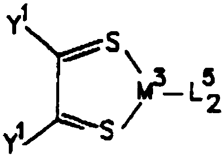

Applications Claiming Priority (1)
| Application Number | Priority Date | Filing Date | Title |
|---|---|---|---|
| US08/354,674 US5707745A (en) | 1994-12-13 | 1994-12-13 | Multicolor organic light emitting devices |
Publications (2)
| Publication Number | Publication Date |
|---|---|
| FR2728082A1 true FR2728082A1 (en) | 1996-06-14 |
| FR2728082B1 FR2728082B1 (en) | 1999-05-28 |
Family
ID=23394434
Family Applications (3)
| Application Number | Title | Priority Date | Filing Date |
|---|---|---|---|
| FR9514793A Expired - Fee Related FR2728082B1 (en) | 1994-12-13 | 1995-12-13 | COLOR LIGHT ORGANIC STRUCTURES AND DISPLAYS AND METHODS OF MAKING SAME |
| FR9605901A Expired - Fee Related FR2732480B1 (en) | 1994-12-13 | 1996-05-13 | METHOD FOR MANUFACTURING HERMETICALLY ENCAPSULATED COLOR LIGHTING DEVICES |
| FR9605902A Expired - Fee Related FR2732481B1 (en) | 1994-12-13 | 1996-05-13 | EXCITABLE TRANSPARENT LIGHT DEVICE |
Family Applications After (2)
| Application Number | Title | Priority Date | Filing Date |
|---|---|---|---|
| FR9605901A Expired - Fee Related FR2732480B1 (en) | 1994-12-13 | 1996-05-13 | METHOD FOR MANUFACTURING HERMETICALLY ENCAPSULATED COLOR LIGHTING DEVICES |
| FR9605902A Expired - Fee Related FR2732481B1 (en) | 1994-12-13 | 1996-05-13 | EXCITABLE TRANSPARENT LIGHT DEVICE |
Country Status (21)
| Country | Link |
|---|---|
| US (5) | US5707745A (en) |
| EP (2) | EP0808244B1 (en) |
| JP (2) | JP3496681B2 (en) |
| KR (1) | KR100419020B1 (en) |
| CN (3) | CN1236410C (en) |
| AR (1) | AR001331A1 (en) |
| AT (1) | ATE220246T1 (en) |
| AU (1) | AU690413B2 (en) |
| BR (1) | BR9510076A (en) |
| CA (1) | CA2206769A1 (en) |
| DE (2) | DE69527308T2 (en) |
| ES (1) | ES2117590B1 (en) |
| FI (1) | FI972176A (en) |
| FR (3) | FR2728082B1 (en) |
| GB (1) | GB2313478B (en) |
| IT (1) | IT1277977B1 (en) |
| NO (1) | NO972706L (en) |
| PL (1) | PL179550B1 (en) |
| RU (1) | RU2160470C2 (en) |
| TW (1) | TW294842B (en) |
| WO (1) | WO1996019792A2 (en) |
Cited By (3)
| Publication number | Priority date | Publication date | Assignee | Title |
|---|---|---|---|---|
| EP0886329A2 (en) * | 1997-06-16 | 1998-12-23 | Canon Kabushiki Kaisha | Electroluminescence device, electroluminescence apparatus, and production methods thereof |
| FR2797084A1 (en) * | 1999-07-26 | 2001-02-02 | Giesecke & Devrient Gmbh | CHIP CARD DISPLAY |
| US8963420B2 (en) | 2011-08-29 | 2015-02-24 | Lg Display Co., Ltd. | Organic electro-luminescence display panel for preventing the display panel from degrading and a method for fabricating the same |
Families Citing this family (1691)
| Publication number | Priority date | Publication date | Assignee | Title |
|---|---|---|---|---|
| US6358631B1 (en) | 1994-12-13 | 2002-03-19 | The Trustees Of Princeton University | Mixed vapor deposited films for electroluminescent devices |
| US5707745A (en) | 1994-12-13 | 1998-01-13 | The Trustees Of Princeton University | Multicolor organic light emitting devices |
| US6548956B2 (en) | 1994-12-13 | 2003-04-15 | The Trustees Of Princeton University | Transparent contacts for organic devices |
| US5703436A (en) * | 1994-12-13 | 1997-12-30 | The Trustees Of Princeton University | Transparent contacts for organic devices |
| GB2312326B (en) | 1995-04-18 | 1999-07-28 | Cambridge Display Tech Ltd | Electroluminescent device |
| JP2982699B2 (en) * | 1995-08-04 | 1999-11-29 | 東洋インキ製造株式会社 | Material for forming electron injection layer of multilayer organic electroluminescence device |
| US5940683A (en) * | 1996-01-18 | 1999-08-17 | Motorola, Inc. | LED display packaging with substrate removal and method of fabrication |
| JP3552435B2 (en) * | 1996-12-04 | 2004-08-11 | 株式会社日立製作所 | Organic light emitting device and method for producing the same |
| JP3537591B2 (en) * | 1996-04-26 | 2004-06-14 | パイオニア株式会社 | Manufacturing method of organic EL display |
| US6048630A (en) | 1996-07-02 | 2000-04-11 | The Trustees Of Princeton University | Red-emitting organic light emitting devices (OLED's) |
| US5998085A (en) * | 1996-07-23 | 1999-12-07 | 3M Innovative Properties | Process for preparing high resolution emissive arrays and corresponding articles |
| JPH1055887A (en) * | 1996-08-08 | 1998-02-24 | Denso Corp | Matrix display device |
| ATE320085T1 (en) * | 1996-08-12 | 2006-03-15 | Univ Princeton | NON-POLYMERIC FLEXIBLE ORGANIC LIGHT EMITTING COMPONENT AND PRODUCTION METHOD |
| JP3899566B2 (en) * | 1996-11-25 | 2007-03-28 | セイコーエプソン株式会社 | Manufacturing method of organic EL display device |
| US6002206A (en) * | 1996-11-28 | 1999-12-14 | Cambridge Display Technology Limited | Organic EL devices and operation thereof |
| CA2223167C (en) | 1996-12-04 | 2004-04-27 | Hitachi, Ltd. | Organic light emitting element and producing method thereof |
| US6046543A (en) * | 1996-12-23 | 2000-04-04 | The Trustees Of Princeton University | High reliability, high efficiency, integratable organic light emitting devices and methods of producing same |
| US6091195A (en) * | 1997-02-03 | 2000-07-18 | The Trustees Of Princeton University | Displays having mesa pixel configuration |
| US6045930A (en) * | 1996-12-23 | 2000-04-04 | The Trustees Of Princeton University | Materials for multicolor light emitting diodes |
| US5861219A (en) * | 1997-04-15 | 1999-01-19 | The Trustees Of Princeton University | Organic light emitting devices containing a metal complex of 5-hydroxy-quinoxaline as a host material |
| US5874803A (en) * | 1997-09-09 | 1999-02-23 | The Trustees Of Princeton University | Light emitting device with stack of OLEDS and phosphor downconverter |
| US6125226A (en) * | 1997-04-18 | 2000-09-26 | The Trustees Of Princeton University | Light emitting devices having high brightness |
| US6013982A (en) | 1996-12-23 | 2000-01-11 | The Trustees Of Princeton University | Multicolor display devices |
| US5986401A (en) * | 1997-03-20 | 1999-11-16 | The Trustee Of Princeton University | High contrast transparent organic light emitting device display |
| US5981306A (en) * | 1997-09-12 | 1999-11-09 | The Trustees Of Princeton University | Method for depositing indium tin oxide layers in organic light emitting devices |
| US5811833A (en) * | 1996-12-23 | 1998-09-22 | University Of So. Ca | Electron transporting and light emitting layers based on organic free radicals |
| US5739545A (en) * | 1997-02-04 | 1998-04-14 | International Business Machines Corporation | Organic light emitting diodes having transparent cathode structures |
| US6111902A (en) | 1997-05-09 | 2000-08-29 | The Trustees Of Princeton University | Organic semiconductor laser |
| US5932895A (en) * | 1997-05-20 | 1999-08-03 | The Trustees Of Princeton University | Saturated full color stacked organic light emitting devices |
| JP2000515309A (en) * | 1997-05-22 | 2000-11-14 | コーニンクレッカ フィリップス エレクトロニクス エヌ ヴィ | Organic electroluminescent device |
| GB9711237D0 (en) * | 1997-06-02 | 1997-07-23 | Isis Innovation | Organomettallic Complexes |
| US6452218B1 (en) * | 1997-06-10 | 2002-09-17 | Uniax Corporation | Ultra-thin alkaline earth metals as stable electron-injecting electrodes for polymer light emitting diodes |
| GB9712483D0 (en) | 1997-06-17 | 1997-08-20 | Kathirgamanathan Poopathy | Fabrication of light emitting devices from chelates of transition metals, lanthanides and actinides |
| EP1021255A1 (en) * | 1997-07-11 | 2000-07-26 | Fed Corporation | Sealing structure for organic light emitting devices |
| US6198220B1 (en) * | 1997-07-11 | 2001-03-06 | Emagin Corporation | Sealing structure for organic light emitting devices |
| KR20010021742A (en) * | 1997-07-11 | 2001-03-15 | 게리 더블유. 존스 | Laser ablation method to fabricate color organic light emitting diode displays |
| US6337492B1 (en) * | 1997-07-11 | 2002-01-08 | Emagin Corporation | Serially-connected organic light emitting diode stack having conductors sandwiching each light emitting layer |
| JP3994482B2 (en) * | 1997-08-27 | 2007-10-17 | 双葉電子工業株式会社 | Multi-color organic electroluminescence device and manufacturing method thereof |
| US6043550A (en) | 1997-09-03 | 2000-03-28 | Sumitomo Electric Industries, Ltd. | Photodiode and photodiode module |
| US5965907A (en) * | 1997-09-29 | 1999-10-12 | Motorola, Inc. | Full color organic light emitting backlight device for liquid crystal display applications |
| EP1536496A1 (en) | 1997-10-09 | 2005-06-01 | The Trustees Of Princeton University | Organic light emitting device |
| US6150043A (en) * | 1998-04-10 | 2000-11-21 | The Trustees Of Princeton University | OLEDs containing thermally stable glassy organic hole transporting materials |
| US6451455B1 (en) | 1998-04-01 | 2002-09-17 | The Trustees Of Princeton University | Metal complexes bearing both electron transporting and hole transporting moieties |
| US6469437B1 (en) | 1997-11-03 | 2002-10-22 | The Trustees Of Princeton University | Highly transparent organic light emitting device employing a non-metallic cathode |
| US6030715A (en) * | 1997-10-09 | 2000-02-29 | The University Of Southern California | Azlactone-related dopants in the emissive layer of an OLED |
| US6303238B1 (en) * | 1997-12-01 | 2001-10-16 | The Trustees Of Princeton University | OLEDs doped with phosphorescent compounds |
| US6420031B1 (en) | 1997-11-03 | 2002-07-16 | The Trustees Of Princeton University | Highly transparent non-metallic cathodes |
| US6413656B1 (en) | 1998-09-14 | 2002-07-02 | The University Of Southern California | Reduced symmetry porphyrin molecules for producing enhanced luminosity from phosphorescent organic light emitting devices |
| US6337102B1 (en) * | 1997-11-17 | 2002-01-08 | The Trustees Of Princeton University | Low pressure vapor phase deposition of organic thin films |
| GB9724682D0 (en) | 1997-11-21 | 1998-01-21 | Cambridge Display Tech Ltd | Electroluminescent device |
| US6013538A (en) * | 1997-11-24 | 2000-01-11 | The Trustees Of Princeton University | Method of fabricating and patterning OLEDs |
| US5953587A (en) * | 1997-11-24 | 1999-09-14 | The Trustees Of Princeton University | Method for deposition and patterning of organic thin film |
| US6075316A (en) * | 1997-12-15 | 2000-06-13 | Motorola, Inc. | Full color organic electroluminescent display device and method of fabrication |
| US6209118B1 (en) * | 1998-01-21 | 2001-03-27 | Micron Technology, Inc. | Method for modifying an integrated circuit |
| US5994836A (en) * | 1998-02-02 | 1999-11-30 | Ois Optical Imaging Systems, Inc. | Organic light emitting diode (OLED) structure and method of making same |
| US6106352A (en) * | 1998-03-18 | 2000-08-22 | Sanyo Electric Co., Ltd. | Method for fabrication of organic electroluminescent device |
| US6316098B1 (en) | 1998-03-27 | 2001-11-13 | Yissum Research Development Company Of The Hebrew University Of Jerusalem | Molecular layer epitaxy method and compositions |
| US6783849B2 (en) * | 1998-03-27 | 2004-08-31 | Yissum Research Development Company Of The Hebrew University Of Jerusalem | Molecular layer epitaxy method and compositions |
| US6287712B1 (en) | 1998-04-10 | 2001-09-11 | The Trustees Of Princeton University | Color-tunable organic light emitting devices |
| US6312836B1 (en) | 1998-04-10 | 2001-11-06 | The Trustees Of Princeton University | Color-tunable organic light emitting devices |
| US6210814B1 (en) | 1998-04-10 | 2001-04-03 | The University Of Southern California | Color-tunable organic light emitting devices |
| US6387544B1 (en) | 1998-04-10 | 2002-05-14 | The Trustees Of Princeton University | OLEDS containing thermally stable glassy organic hole transporting materials |
| US6120857A (en) * | 1998-05-18 | 2000-09-19 | The Regents Of The University Of California | Low work function surface layers produced by laser ablation using short-wavelength photons |
| JP3884564B2 (en) * | 1998-05-20 | 2007-02-21 | 出光興産株式会社 | Organic EL light emitting device and light emitting device using the same |
| EP0966050A3 (en) * | 1998-06-18 | 2004-11-17 | Osram Opto Semiconductors GmbH & Co. OHG | Organic light emitting diode |
| JP4264994B2 (en) * | 1998-07-10 | 2009-05-20 | 凸版印刷株式会社 | Method for manufacturing organic electroluminescence display element |
| EP1039784B1 (en) * | 1998-09-02 | 2006-03-29 | Seiko Epson Corporation | Light source and display device |
| US6097147A (en) * | 1998-09-14 | 2000-08-01 | The Trustees Of Princeton University | Structure for high efficiency electroluminescent device |
| US6830828B2 (en) | 1998-09-14 | 2004-12-14 | The Trustees Of Princeton University | Organometallic complexes as phosphorescent emitters in organic LEDs |
| US6166489A (en) * | 1998-09-15 | 2000-12-26 | The Trustees Of Princeton University | Light emitting device using dual light emitting stacks to achieve full-color emission |
| JP2000098116A (en) * | 1998-09-18 | 2000-04-07 | Canon Inc | Element or manufacture of mold for manufacturing element |
| US6214631B1 (en) | 1998-10-30 | 2001-04-10 | The Trustees Of Princeton University | Method for patterning light emitting devices incorporating a movable mask |
| GB9823761D0 (en) * | 1998-11-02 | 1998-12-23 | South Bank Univ Entpr Ltd | Novel electroluminescent materials |
| US6037190A (en) * | 1998-11-13 | 2000-03-14 | Industrial Technology Research Institute | Method for fabricating an organic electro-luminescent device |
| DE19854899C1 (en) * | 1998-11-27 | 1999-12-30 | Siemens Ag | Lighting unit for automobile |
| GB9826407D0 (en) | 1998-12-02 | 1999-01-27 | South Bank Univ Entpr Ltd | Novel electroluminescent materials |
| GB9826405D0 (en) | 1998-12-02 | 1999-01-27 | South Bank Univ Entpr Ltd | Method for forming films or layers |
| JP2000195664A (en) | 1998-12-24 | 2000-07-14 | Rohm Co Ltd | Luminescent device |
| US6114088A (en) | 1999-01-15 | 2000-09-05 | 3M Innovative Properties Company | Thermal transfer element for forming multilayer devices |
| EP1144197B1 (en) | 1999-01-15 | 2003-06-11 | 3M Innovative Properties Company | Thermal Transfer Method. |
| GB9901971D0 (en) | 1999-02-01 | 1999-03-17 | South Bank Univ Entpr Ltd | Electroluminescent material |
| JP3887984B2 (en) * | 1999-02-05 | 2007-02-28 | 松下電器産業株式会社 | Multicolor light emitting dispersion type EL lamp |
| JP3594826B2 (en) | 1999-02-09 | 2004-12-02 | パイオニア株式会社 | Nitride semiconductor light emitting device and method of manufacturing the same |
| DE69904137T2 (en) | 1999-02-26 | 2004-03-18 | Agfa-Gevaert | Layer based on a conductive metal oxide |
| US7001536B2 (en) * | 1999-03-23 | 2006-02-21 | The Trustees Of Princeton University | Organometallic complexes as phosphorescent emitters in organic LEDs |
| BRPI0009215B1 (en) | 1999-03-23 | 2017-05-09 | Univ Southern California | cyclometallized metal complexes as phosphorescent dopants in organic light-emitting diodes |
| US6262710B1 (en) * | 1999-05-25 | 2001-07-17 | Intel Corporation | Performing color conversion in extended color polymer displays |
| JP4136185B2 (en) * | 1999-05-12 | 2008-08-20 | パイオニア株式会社 | Organic electroluminescent multicolor display and method for manufacturing the same |
| AU4833800A (en) * | 1999-05-13 | 2000-12-05 | University Of Southern California | Titanium nitride anode for use in organic light emitting devices |
| US6727521B2 (en) * | 2000-09-25 | 2004-04-27 | Foveon, Inc. | Vertical color filter detector group and array |
| TW437104B (en) * | 1999-05-25 | 2001-05-28 | Wang Tien Yang | Semiconductor light-emitting device and method for manufacturing the same |
| JP2001035660A (en) * | 1999-07-16 | 2001-02-09 | Fuji Photo Film Co Ltd | Organic electroluminescence element |
| US6310360B1 (en) | 1999-07-21 | 2001-10-30 | The Trustees Of Princeton University | Intersystem crossing agents for efficient utilization of excitons in organic light emitting devices |
| US6506505B1 (en) | 1999-08-16 | 2003-01-14 | The University Of Southern California | Cyclooctatetraenes as electron transporters in organic light emitting diodes |
| AU6643800A (en) | 1999-08-16 | 2001-03-13 | University Of Southern California | Synthesis of cyclooctatetraene derivatives and their use as electron transporters in organic light emitting diodes |
| US6593690B1 (en) * | 1999-09-03 | 2003-07-15 | 3M Innovative Properties Company | Large area organic electronic devices having conducting polymer buffer layers and methods of making same |
| US6611096B1 (en) | 1999-09-03 | 2003-08-26 | 3M Innovative Properties Company | Organic electronic devices having conducting self-doped polymer buffer layers |
| JP2001111109A (en) * | 1999-10-07 | 2001-04-20 | Sharp Corp | Gallium nitride compound semiconductor light emitting device |
| US6214151B1 (en) | 1999-11-05 | 2001-04-10 | International Business Machines Corporation | Thermal dye transfer process for preparing opto-electronic devices |
| JP2001135479A (en) * | 1999-11-08 | 2001-05-18 | Canon Inc | Light-emitting element and image-reading device using it, information-processing device and display device |
| US7202506B1 (en) * | 1999-11-19 | 2007-04-10 | Cree, Inc. | Multi element, multi color solid state LED/laser |
| US8829546B2 (en) * | 1999-11-19 | 2014-09-09 | Cree, Inc. | Rare earth doped layer or substrate for light conversion |
| US6294398B1 (en) | 1999-11-23 | 2001-09-25 | The Trustees Of Princeton University | Method for patterning devices |
| US6458475B1 (en) | 1999-11-24 | 2002-10-01 | The Trustee Of Princeton University | Organic light emitting diode having a blue phosphorescent molecule as an emitter |
| EP2270895A3 (en) | 1999-12-01 | 2011-03-30 | The Trustees of Princeton University | Complexes for OLEDs |
| US6537607B1 (en) | 1999-12-17 | 2003-03-25 | Texas Instruments Incorporated | Selective deposition of emissive layer in electroluminescent displays |
| US6639357B1 (en) | 2000-02-28 | 2003-10-28 | The Trustees Of Princeton University | High efficiency transparent organic light emitting devices |
| KR20010095429A (en) * | 2000-03-30 | 2001-11-07 | 윤덕용 | Organic Electroluminescent Devices Using a Single Ion Conductor as an Electron or a Hole Injecting Material |
| JP2001284631A (en) * | 2000-03-30 | 2001-10-12 | Toshiba Corp | Photodetector and photodetection system |
| US6661029B1 (en) * | 2000-03-31 | 2003-12-09 | General Electric Company | Color tunable organic electroluminescent light source |
| JP2001341296A (en) * | 2000-03-31 | 2001-12-11 | Seiko Epson Corp | Method for forming thin film by ink jet, ink jet unit, organic el element, and method for manufacturing the same |
| US6913713B2 (en) * | 2002-01-25 | 2005-07-05 | Konarka Technologies, Inc. | Photovoltaic fibers |
| US6645645B1 (en) | 2000-05-30 | 2003-11-11 | The Trustees Of Princeton University | Phosphorescent organic light emitting devices |
| AU2001269790A1 (en) * | 2000-06-12 | 2001-12-24 | Maxdem Incorporated | Polymer matrix electroluminescent materials and devices |
| US6840999B2 (en) * | 2000-07-25 | 2005-01-11 | Board Of Regents The University Of Texas System | In situ regrowth and purification of crystalline thin films |
| DE10037391A1 (en) | 2000-08-01 | 2002-02-14 | Covion Organic Semiconductors | Structurable materials, processes for their production and their use |
| TW528967B (en) | 2000-08-29 | 2003-04-21 | Ibm | System and method for locating on a physical document items referenced in an electronic document |
| TW494323B (en) * | 2000-08-29 | 2002-07-11 | Ibm | System and method for locating on a physical document items referenced in another physical document |
| US6525464B1 (en) * | 2000-09-08 | 2003-02-25 | Unity Opto Technology Co., Ltd. | Stacked light-mixing LED |
| JP3560150B2 (en) * | 2000-09-14 | 2004-09-02 | 日本精機株式会社 | Organic EL device |
| US6855384B1 (en) | 2000-09-15 | 2005-02-15 | 3M Innovative Properties Company | Selective thermal transfer of light emitting polymer blends |
| US6358664B1 (en) | 2000-09-15 | 2002-03-19 | 3M Innovative Properties Company | Electronically active primer layers for thermal patterning of materials for electronic devices |
| JP4067286B2 (en) * | 2000-09-21 | 2008-03-26 | 富士フイルム株式会社 | Light emitting device and iridium complex |
| US6617186B2 (en) | 2000-09-25 | 2003-09-09 | Dai Nippon Printing Co., Ltd. | Method for producing electroluminescent element |
| US6884093B2 (en) * | 2000-10-03 | 2005-04-26 | The Trustees Of Princeton University | Organic triodes with novel grid structures and method of production |
| US7288014B1 (en) | 2000-10-27 | 2007-10-30 | Science Applications International Corporation | Design, fabrication, testing, and conditioning of micro-components for use in a light-emitting panel |
| US6801001B2 (en) * | 2000-10-27 | 2004-10-05 | Science Applications International Corporation | Method and apparatus for addressing micro-components in a plasma display panel |
| US6762566B1 (en) | 2000-10-27 | 2004-07-13 | Science Applications International Corporation | Micro-component for use in a light-emitting panel |
| US6935913B2 (en) * | 2000-10-27 | 2005-08-30 | Science Applications International Corporation | Method for on-line testing of a light emitting panel |
| US6612889B1 (en) | 2000-10-27 | 2003-09-02 | Science Applications International Corporation | Method for making a light-emitting panel |
| US6545422B1 (en) * | 2000-10-27 | 2003-04-08 | Science Applications International Corporation | Socket for use with a micro-component in a light-emitting panel |
| US6796867B2 (en) * | 2000-10-27 | 2004-09-28 | Science Applications International Corporation | Use of printing and other technology for micro-component placement |
| US6620012B1 (en) * | 2000-10-27 | 2003-09-16 | Science Applications International Corporation | Method for testing a light-emitting panel and the components therein |
| US6570335B1 (en) | 2000-10-27 | 2003-05-27 | Science Applications International Corporation | Method and system for energizing a micro-component in a light-emitting panel |
| US6822626B2 (en) * | 2000-10-27 | 2004-11-23 | Science Applications International Corporation | Design, fabrication, testing, and conditioning of micro-components for use in a light-emitting panel |
| US6764367B2 (en) | 2000-10-27 | 2004-07-20 | Science Applications International Corporation | Liquid manufacturing processes for panel layer fabrication |
| US20030129299A1 (en) * | 2000-11-16 | 2003-07-10 | Swanson Leland S. | Selective deposition of emissive layer in electroluminescent displays |
| GB0028436D0 (en) * | 2000-11-21 | 2001-01-10 | South Bank Univ Entpr Ltd | Electroluminescent device incorporating conjugated polymer |
| GB0028317D0 (en) * | 2000-11-21 | 2001-01-03 | South Bank Univ Entpr Ltd | Electroluminescent device incorporating polyaniline |
| GB0028439D0 (en) * | 2000-11-21 | 2001-01-10 | South Bank Univ Entpr Ltd | Elecroluminescent device |
| US6844957B2 (en) * | 2000-11-29 | 2005-01-18 | International Business Machines Corporation | Three level stacked reflective display |
| US6537688B2 (en) | 2000-12-01 | 2003-03-25 | Universal Display Corporation | Adhesive sealed organic optoelectronic structures |
| US6573651B2 (en) * | 2000-12-18 | 2003-06-03 | The Trustees Of Princeton University | Highly efficient OLEDs using doped ambipolar conductive molecular organic thin films |
| KR100685917B1 (en) * | 2000-12-27 | 2007-02-22 | 엘지.필립스 엘시디 주식회사 | Electro luminescence device and method for manufacturing the same |
| US6614175B2 (en) | 2001-01-26 | 2003-09-02 | Xerox Corporation | Organic light emitting devices |
| JP4292245B2 (en) | 2001-02-05 | 2009-07-08 | 三星モバイルディスプレイ株式會社 | Luminescent body, light emitting element, and light emitting display device |
| US6614057B2 (en) | 2001-02-07 | 2003-09-02 | Universal Display Corporation | Sealed organic optoelectronic structures |
| US6762124B2 (en) | 2001-02-14 | 2004-07-13 | Avery Dennison Corporation | Method for patterning a multilayered conductor/substrate structure |
| US20020110673A1 (en) | 2001-02-14 | 2002-08-15 | Ramin Heydarpour | Multilayered electrode/substrate structures and display devices incorporating the same |
| US6576351B2 (en) | 2001-02-16 | 2003-06-10 | Universal Display Corporation | Barrier region for optoelectronic devices |
| US6692662B2 (en) * | 2001-02-16 | 2004-02-17 | Elecon, Inc. | Compositions produced by solvent exchange methods and uses thereof |
| JP4116260B2 (en) * | 2001-02-23 | 2008-07-09 | 株式会社東芝 | Semiconductor light emitting device |
| WO2002071813A1 (en) | 2001-03-02 | 2002-09-12 | The Trustees Of Princeton University | Double doped-layer, phosphorescent organic light emitting devices |
| US6596443B2 (en) | 2001-03-12 | 2003-07-22 | Universal Display Corporation | Mask for patterning devices |
| US6407408B1 (en) | 2001-03-12 | 2002-06-18 | Universal Display Corporation | Method for patterning devices |
| US7294849B2 (en) * | 2001-03-14 | 2007-11-13 | The Trustees Of Princeton University | Materials and devices for blue phosphorescence based organic light emitting diodes |
| US6624568B2 (en) | 2001-03-28 | 2003-09-23 | Universal Display Corporation | Multilayer barrier region containing moisture- and oxygen-absorbing material for optoelectronic devices |
| US6664137B2 (en) | 2001-03-29 | 2003-12-16 | Universal Display Corporation | Methods and structures for reducing lateral diffusion through cooperative barrier layers |
| DE10117663B4 (en) * | 2001-04-09 | 2004-09-02 | Samsung SDI Co., Ltd., Suwon | Process for the production of matrix arrangements based on various types of organic conductive materials |
| US6895667B2 (en) * | 2001-04-13 | 2005-05-24 | The Trustees Of Princeton University | Transfer of patterned metal by cold-welding |
| GB0109755D0 (en) * | 2001-04-20 | 2001-06-13 | Elam T Ltd | Devices incorporating mixed metal organic complexes |
| US6485884B2 (en) | 2001-04-27 | 2002-11-26 | 3M Innovative Properties Company | Method for patterning oriented materials for organic electronic displays and devices |
| CN1302565C (en) * | 2001-05-16 | 2007-02-28 | 普林斯顿大学理事会 | High efficiency multi-color electro-phosphorescent OLEDs |
| WO2002094965A1 (en) * | 2001-05-24 | 2002-11-28 | Idemitsu Kosan Co., Ltd. | Organic electroluminescence element |
| GB2376555B (en) * | 2001-06-14 | 2003-05-28 | Charles Eickhoff | Three dimensional solid colour display |
| TWI303533B (en) * | 2001-06-15 | 2008-11-21 | Oled T Ltd | Electroluminescent devices |
| DE10132329B4 (en) * | 2001-06-29 | 2005-02-24 | Schrader, Karl-Heinz Sigurd, Dr. | Light-emitting device and method for its production |
| GB0116644D0 (en) * | 2001-07-09 | 2001-08-29 | Elam T Ltd | Electroluminescent materials and devices |
| US6664730B2 (en) | 2001-07-09 | 2003-12-16 | Universal Display Corporation | Electrode structure of el device |
| US6984934B2 (en) * | 2001-07-10 | 2006-01-10 | The Trustees Of Princeton University | Micro-lens arrays for display intensity enhancement |
| ITRM20010471A1 (en) * | 2001-08-02 | 2003-02-03 | Enea Ente Nuove Tec | LUMINESCENCE STABILIZATION FROM ORGANIC MATERIALS WITH PHENOLIC ORIGIN COMPOSTIDES. |
| EP1414927A1 (en) * | 2001-08-04 | 2004-05-06 | Elam-T Limited | Electroluminescent device |
| US6569697B2 (en) * | 2001-08-20 | 2003-05-27 | Universal Display Corporation | Method of fabricating electrodes |
| US7071615B2 (en) * | 2001-08-20 | 2006-07-04 | Universal Display Corporation | Transparent electrodes |
| US6888307B2 (en) * | 2001-08-21 | 2005-05-03 | Universal Display Corporation | Patterned oxygen and moisture absorber for organic optoelectronic device structures |
| KR100918988B1 (en) | 2001-08-29 | 2009-09-25 | 더 트러스티즈 오브 프린스턴 유니버시티 | Use of metal complexes to facilitate hole transport in light emitting devices, and methods for fabrication thereof |
| EP2555274B1 (en) | 2001-08-29 | 2020-06-24 | The Trustees of Princeton University | Organic light emitting devices having carrier blocking layers comprising metal complexes |
| US6716656B2 (en) | 2001-09-04 | 2004-04-06 | The Trustees Of Princeton University | Self-aligned hybrid deposition |
| US7744957B2 (en) * | 2003-10-23 | 2010-06-29 | The Trustees Of Princeton University | Method and apparatus for depositing material |
| US7431968B1 (en) * | 2001-09-04 | 2008-10-07 | The Trustees Of Princeton University | Process and apparatus for organic vapor jet deposition |
| EP2275587B1 (en) | 2001-09-04 | 2020-03-18 | The Trustees of Princeton University | Process for organic vapor jet deposition |
| US7404862B2 (en) * | 2001-09-04 | 2008-07-29 | The Trustees Of Princeton University | Device and method for organic vapor jet deposition |
| US8535759B2 (en) * | 2001-09-04 | 2013-09-17 | The Trustees Of Princeton University | Method and apparatus for depositing material using a dynamic pressure |
| US20030054197A1 (en) * | 2001-09-20 | 2003-03-20 | Raymond Kwong | Annealing modified interface in organic light emitting devices |
| US7071613B2 (en) * | 2001-10-10 | 2006-07-04 | Lg.Philips Lcd Co., Ltd. | Organic electroluminescent device |
| US6835469B2 (en) | 2001-10-17 | 2004-12-28 | The University Of Southern California | Phosphorescent compounds and devices comprising the same |
| US20050156839A1 (en) * | 2001-11-02 | 2005-07-21 | Webb Homer L. | Field sequential display device and methods of fabricating same |
| US6888305B2 (en) * | 2001-11-06 | 2005-05-03 | Universal Display Corporation | Encapsulation structure that acts as a multilayer mirror |
| DE60230314D1 (en) * | 2001-11-13 | 2009-01-22 | Ibm | SYSTEM AND METHOD FOR SELECTING AN ELECTRONIC DOCUMENT FROM A PHYSICAL DOCUMENT AND DISPLAYING THIS ELECTRONIC DOCUMENT THROUGH THIS PHYSICAL DOCUMENT |
| US6734457B2 (en) * | 2001-11-27 | 2004-05-11 | Semiconductor Energy Laboratory Co., Ltd. | Light emitting device |
| US6597111B2 (en) | 2001-11-27 | 2003-07-22 | Universal Display Corporation | Protected organic optoelectronic devices |
| US7053547B2 (en) * | 2001-11-29 | 2006-05-30 | Universal Display Corporation | Increased emission efficiency in organic light-emitting devices on high-index substrates |
| SG142163A1 (en) | 2001-12-05 | 2008-05-28 | Semiconductor Energy Lab | Organic semiconductor element |
| CN100392873C (en) * | 2001-12-07 | 2008-06-04 | 张修恒 | Structure and method for packaging colour light-emitting diode with stacked wafer |
| US7050835B2 (en) | 2001-12-12 | 2006-05-23 | Universal Display Corporation | Intelligent multi-media display communication system |
| US6765351B2 (en) * | 2001-12-20 | 2004-07-20 | The Trustees Of Princeton University | Organic optoelectronic device structures |
| US20030117378A1 (en) * | 2001-12-21 | 2003-06-26 | International Business Machines Corporation | Device and system for retrieving and displaying handwritten annotations |
| US6555284B1 (en) * | 2001-12-27 | 2003-04-29 | Eastman Kodak Company | In situ vacuum method for making OLED devices |
| US6869695B2 (en) | 2001-12-28 | 2005-03-22 | The Trustees Of Princeton University | White light emitting OLEDs from combined monomer and aggregate emission |
| US6863997B2 (en) * | 2001-12-28 | 2005-03-08 | The Trustees Of Princeton University | White light emitting OLEDs from combined monomer and aggregate emission |
| US7012363B2 (en) * | 2002-01-10 | 2006-03-14 | Universal Display Corporation | OLEDs having increased external electroluminescence quantum efficiencies |
| US20030153240A1 (en) * | 2002-02-14 | 2003-08-14 | Dejule Aaron M. | Hanging mobile device with electronic display |
| US6872472B2 (en) * | 2002-02-15 | 2005-03-29 | Eastman Kodak Company | Providing an organic electroluminescent device having stacked electroluminescent units |
| US6876143B2 (en) * | 2002-11-19 | 2005-04-05 | John James Daniels | Organic light active devices and methods for fabricating the same |
| US20100026176A1 (en) * | 2002-03-28 | 2010-02-04 | Jan Blochwitz-Nomith | Transparent, Thermally Stable Light-Emitting Component Having Organic Layers |
| DE10215210B4 (en) * | 2002-03-28 | 2006-07-13 | Novaled Gmbh | Transparent, thermally stable light-emitting component with organic layers |
| US6951694B2 (en) * | 2002-03-29 | 2005-10-04 | The University Of Southern California | Organic light emitting devices with electron blocking layers |
| US8294172B2 (en) | 2002-04-09 | 2012-10-23 | Lg Electronics Inc. | Method of fabricating vertical devices using a metal support film |
| US20030189215A1 (en) | 2002-04-09 | 2003-10-09 | Jong-Lam Lee | Method of fabricating vertical structure leds |
| JP2003308968A (en) * | 2002-04-12 | 2003-10-31 | Rohm Co Ltd | Electroluminescent element and method of manufacturing the same |
| US6897474B2 (en) * | 2002-04-12 | 2005-05-24 | Universal Display Corporation | Protected organic electronic devices and methods for making the same |
| US6835950B2 (en) | 2002-04-12 | 2004-12-28 | Universal Display Corporation | Organic electronic devices with pressure sensitive adhesive layer |
| WO2003090502A2 (en) * | 2002-04-19 | 2003-10-30 | 3M Innovative Properties Company | Materials for organic electronic devices |
| JP4544811B2 (en) * | 2002-05-09 | 2010-09-15 | 大日本印刷株式会社 | Method for manufacturing electroluminescent device |
| TW589915B (en) * | 2002-05-24 | 2004-06-01 | Sanyo Electric Co | Electroluminescence display device |
| DE10224021B4 (en) * | 2002-05-24 | 2006-06-01 | Novaled Gmbh | Phosphorescent light emitting device with organic layers |
| US7416791B1 (en) | 2002-06-11 | 2008-08-26 | University Of Washington | Osmium complexes and related organic light-emitting devices |
| US6811815B2 (en) * | 2002-06-14 | 2004-11-02 | Avery Dennison Corporation | Method for roll-to-roll deposition of optically transparent and high conductivity metallic thin films |
| US20040004433A1 (en) * | 2002-06-26 | 2004-01-08 | 3M Innovative Properties Company | Buffer layers for organic electroluminescent devices and methods of manufacture and use |
| US6841802B2 (en) * | 2002-06-26 | 2005-01-11 | Oriol, Inc. | Thin film light emitting diode |
| DE10231140A1 (en) * | 2002-07-10 | 2004-01-29 | Fraunhofer-Gesellschaft zur Förderung der angewandten Forschung e.V. | Optoelectronic component with electrically conductive organic material and method for producing the component |
| US6642092B1 (en) * | 2002-07-11 | 2003-11-04 | Sharp Laboratories Of America, Inc. | Thin-film transistors formed on a metal foil substrate |
| TWI338528B (en) * | 2002-07-19 | 2011-03-01 | Au Optronics Corp | |
| US6693296B1 (en) * | 2002-08-07 | 2004-02-17 | Eastman Kodak Company | OLED apparatus including a series of OLED devices |
| US6689628B1 (en) * | 2002-08-15 | 2004-02-10 | Bae Systems Information And Electronic Systems Integration Inc. | Method for dense pixel fabrication |
| US6916554B2 (en) * | 2002-11-06 | 2005-07-12 | The University Of Southern California | Organic light emitting materials and devices |
| US7061175B2 (en) * | 2002-08-16 | 2006-06-13 | Universal Display Corporation | Efficiency transparent cathode |
| US7663300B2 (en) | 2002-08-16 | 2010-02-16 | Universal Display Corporation | Organic light emitting devices for illumination |
| EP1534799A4 (en) * | 2002-08-16 | 2008-02-27 | Univ Southern California | Organic light emitting materials and devices |
| CN1681828B (en) * | 2002-08-16 | 2012-05-30 | 南加利福尼亚大学 | Organic light emitting materials with anionic ligand |
| JP4313308B2 (en) * | 2002-08-27 | 2009-08-12 | 富士フイルム株式会社 | Organic metal complex, organic EL element, and organic EL display |
| US20040108509A1 (en) * | 2002-09-03 | 2004-06-10 | Caballero Gabriel Joseph | Light emitting molecules and organic light emitting devices including light emitting molecules |
| US20040191567A1 (en) * | 2002-09-03 | 2004-09-30 | Caballero Gabriel Joseph | Light emitting molecules and organic light emitting devices including light emitting molecules |
| US7574407B2 (en) * | 2002-10-10 | 2009-08-11 | International Business Machines Corporation | System and method for selecting, ordering and accessing copyrighted information from physical documents |
| US6911961B2 (en) * | 2002-10-11 | 2005-06-28 | Eastman Kodak Company | Method of designing an OLED display with lifetime optimized primaries |
| US6853660B2 (en) * | 2002-10-16 | 2005-02-08 | Eastman Kodak Company | Organic laser cavity arrays |
| US7049636B2 (en) * | 2002-10-28 | 2006-05-23 | Universal Display Corporation | Device including OLED controlled by n-type transistor |
| US20040086743A1 (en) * | 2002-11-06 | 2004-05-06 | Brown Cory S. | Organometallic compounds for use in electroluminescent devices |
| US6687266B1 (en) * | 2002-11-08 | 2004-02-03 | Universal Display Corporation | Organic light emitting materials and devices |
| US6858327B2 (en) | 2002-11-08 | 2005-02-22 | Universal Display Corporation | Organic light emitting materials and devices |
| US6717176B1 (en) * | 2002-11-12 | 2004-04-06 | Opto Tech Corporation | White light emitting organic electro-luminescent device and method for fabricating the same |
| US6982179B2 (en) * | 2002-11-15 | 2006-01-03 | University Display Corporation | Structure and method of fabricating organic devices |
| US20040096570A1 (en) * | 2002-11-15 | 2004-05-20 | Michael Weaver | Structure and method of fabricating organic devices |
| US6891326B2 (en) * | 2002-11-15 | 2005-05-10 | Universal Display Corporation | Structure and method of fabricating organic devices |
| JP4072422B2 (en) | 2002-11-22 | 2008-04-09 | 三星エスディアイ株式会社 | Deposition mask structure, method for producing the same, and method for producing organic EL element using the same |
| US6947459B2 (en) * | 2002-11-25 | 2005-09-20 | Eastman Kodak Company | Organic vertical cavity laser and imaging system |
| US7368659B2 (en) * | 2002-11-26 | 2008-05-06 | General Electric Company | Electrodes mitigating effects of defects in organic electronic devices |
| JP4173722B2 (en) | 2002-11-29 | 2008-10-29 | 三星エスディアイ株式会社 | Vapor deposition mask, organic EL element manufacturing method using the same, and organic EL element |
| US7086918B2 (en) * | 2002-12-11 | 2006-08-08 | Applied Materials, Inc. | Low temperature process for passivation applications |
| US7492092B2 (en) * | 2002-12-17 | 2009-02-17 | Seiko Epson Corporation | Self-emitting element, display panel, display apparatus, and method of manufacturing self-emitting element |
| US7338820B2 (en) * | 2002-12-19 | 2008-03-04 | 3M Innovative Properties Company | Laser patterning of encapsulated organic light emitting diodes |
| US6975067B2 (en) * | 2002-12-19 | 2005-12-13 | 3M Innovative Properties Company | Organic electroluminescent device and encapsulation method |
| DE10262143B4 (en) * | 2002-12-20 | 2011-01-20 | Ksg Leiterplatten Gmbh | Light-emitting arrangement |
| US8222072B2 (en) * | 2002-12-20 | 2012-07-17 | The Trustees Of Princeton University | Methods of fabricating devices by low pressure cold welding |
| US7964439B2 (en) | 2002-12-20 | 2011-06-21 | The Trustees Of Princeton University | Methods of fabricating devices by transfer of organic material |
| US7063900B2 (en) | 2002-12-23 | 2006-06-20 | General Electric Company | White light-emitting organic electroluminescent devices |
| JP2004226795A (en) * | 2003-01-24 | 2004-08-12 | Pioneer Electronic Corp | Three-dimensional image display device |
| US6900458B2 (en) * | 2003-02-21 | 2005-05-31 | Universal Display Corporation | Transflective display having an OLED backlight |
| US6995445B2 (en) * | 2003-03-14 | 2006-02-07 | The Trustees Of Princeton University | Thin film organic position sensitive detectors |
| EP3109238B1 (en) * | 2003-03-24 | 2019-09-18 | University of Southern California | Phenyl-pyrazole complexes of iridium |
| US6727660B1 (en) | 2003-03-27 | 2004-04-27 | General Electric Company | Organic electroluminescent devices and method for improving energy efficiency and optical stability thereof |
| US20050227389A1 (en) * | 2004-04-13 | 2005-10-13 | Rabin Bhattacharya | Deformable organic devices |
| US7465678B2 (en) * | 2003-03-28 | 2008-12-16 | The Trustees Of Princeton University | Deformable organic devices |
| US20040199052A1 (en) | 2003-04-01 | 2004-10-07 | Scimed Life Systems, Inc. | Endoscopic imaging system |
| US6902833B2 (en) * | 2003-04-01 | 2005-06-07 | University Of Southern California | Materials and structures for enhancing the performance or organic light emitting devices |
| US7090928B2 (en) * | 2003-04-01 | 2006-08-15 | The University Of Southern California | Binuclear compounds |
| US7018713B2 (en) * | 2003-04-02 | 2006-03-28 | 3M Innovative Properties Company | Flexible high-temperature ultrabarrier |
| US20060063028A1 (en) * | 2003-04-08 | 2006-03-23 | Leurs Jeroom Frans M | Two sided light emitting device |
| US7271406B2 (en) * | 2003-04-15 | 2007-09-18 | 3M Innovative Properties Company | Electron transport agents for organic electronic devices |
| US7192657B2 (en) * | 2003-04-15 | 2007-03-20 | 3M Innovative Properties Company | Ethynyl containing electron transport dyes and compositions |
| US6831302B2 (en) * | 2003-04-15 | 2004-12-14 | Luminus Devices, Inc. | Light emitting devices with improved extraction efficiency |
| US20040209115A1 (en) * | 2003-04-21 | 2004-10-21 | Thompson Mark E. | Organic light emitting devices with wide gap host materials |
| US20040209116A1 (en) * | 2003-04-21 | 2004-10-21 | Xiaofan Ren | Organic light emitting devices with wide gap host materials |
| US7029765B2 (en) * | 2003-04-22 | 2006-04-18 | Universal Display Corporation | Organic light emitting devices having reduced pixel shrinkage |
| JP3902566B2 (en) * | 2003-04-24 | 2007-04-11 | 富士電機ホールディングス株式会社 | Organic EL light emitting device |
| US6853134B2 (en) * | 2003-05-20 | 2005-02-08 | Canon Kabushiki Kaisha | Anode structure for organic light emitting device |
| US7535017B2 (en) * | 2003-05-30 | 2009-05-19 | Osram Opto Semiconductors Gmbh | Flexible multilayer packaging material and electronic devices with the packaging material |
| US20040259070A1 (en) * | 2003-06-20 | 2004-12-23 | Goodstein Shelley R. | Child/infant play and entertainment devices including electronic displays |
| US7553355B2 (en) * | 2003-06-23 | 2009-06-30 | Matheson Tri-Gas | Methods and materials for the reduction and control of moisture and oxygen in OLED devices |
| US7310779B2 (en) * | 2003-06-26 | 2007-12-18 | International Business Machines Corporation | Method for creating and selecting active regions on physical documents |
| US7053412B2 (en) | 2003-06-27 | 2006-05-30 | The Trustees Of Princeton University And Universal Display Corporation | Grey scale bistable display |
| US6885025B2 (en) * | 2003-07-10 | 2005-04-26 | Universal Display Corporation | Organic light emitting device structures for obtaining chromaticity stability |
| US7211823B2 (en) * | 2003-07-10 | 2007-05-01 | Universal Display Corporation | Organic light emitting device structure for obtaining chromaticity stability |
| US6953705B2 (en) | 2003-07-22 | 2005-10-11 | E. I. Du Pont De Nemours And Company | Process for removing an organic layer during fabrication of an organic electronic device |
| US7002292B2 (en) | 2003-07-22 | 2006-02-21 | E. I. Du Pont De Nemours And Company | Organic electronic device |
| US20050025993A1 (en) | 2003-07-25 | 2005-02-03 | Thompson Mark E. | Materials and structures for enhancing the performance of organic light emitting devices |
| US7198859B2 (en) * | 2003-07-25 | 2007-04-03 | Universal Display Corporation | Materials and structures for enhancing the performance of organic light emitting devices |
| US7018723B2 (en) * | 2003-07-25 | 2006-03-28 | The University Of Southern California | Materials and structures for enhancing the performance of organic light emitting devices |
| US20050023974A1 (en) * | 2003-08-01 | 2005-02-03 | Universal Display Corporation | Protected organic electronic devices and methods for making the same |
| JP2007502534A (en) * | 2003-08-12 | 2007-02-08 | コーニンクレッカ フィリップス エレクトロニクス エヌ ヴィ | Circuit arrangement for organic diode AC drive |
| US7275972B2 (en) * | 2003-08-22 | 2007-10-02 | 3M Innovative Properties Company | Method of making an electroluminescent device having a patterned emitter layer and non-patterned emitter layer |
| JP4123106B2 (en) * | 2003-08-22 | 2008-07-23 | ソニー株式会社 | Organic EL device |
| US6998648B2 (en) * | 2003-08-25 | 2006-02-14 | Universal Display Corporation | Protected organic electronic device structures incorporating pressure sensitive adhesive and desiccant |
| DE10342408B4 (en) * | 2003-09-10 | 2008-09-11 | Samsung SDI Co., Ltd., Suwon | Dual photoluminescent display element, display and method |
| JP4823478B2 (en) * | 2003-09-19 | 2011-11-24 | 株式会社半導体エネルギー研究所 | Method for manufacturing light emitting device |
| US7179543B2 (en) * | 2003-10-06 | 2007-02-20 | The Trustees Of Princeton University | Doping of organic opto-electronic devices to extend reliability |
| US8884845B2 (en) * | 2003-10-28 | 2014-11-11 | Semiconductor Energy Laboratory Co., Ltd. | Display device and telecommunication system |
| JP4243237B2 (en) * | 2003-11-10 | 2009-03-25 | 淳二 城戸 | Organic element, organic EL element, organic solar cell, organic FET structure, and organic element manufacturing method |
| US7061011B2 (en) * | 2003-11-26 | 2006-06-13 | The Trustees Of Princeton University | Bipolar organic devices |
| WO2005055331A1 (en) * | 2003-12-02 | 2005-06-16 | Koninklijke Philips Electronics N.V. | Pixel arrangement for an emissive device |
| KR100987451B1 (en) * | 2003-12-04 | 2010-10-13 | 엘지전자 주식회사 | Flat luminescence device |
| US7070867B2 (en) * | 2003-12-05 | 2006-07-04 | The University Of Southern California | OLEDs having n-type doping |
| US20050137459A1 (en) | 2003-12-17 | 2005-06-23 | Scimed Life Systems, Inc. | Medical device with OLED illumination light source |
| JP2005190768A (en) * | 2003-12-25 | 2005-07-14 | Toyota Industries Corp | Lighting apparatus |
| US8796670B2 (en) | 2003-12-26 | 2014-08-05 | Semiconductor Energy Laboratory Co., Ltd. | Light-emitting element |
| US20050164031A1 (en) * | 2004-01-26 | 2005-07-28 | Thompson Mark E. | Dual emitting dyads of heavy metal complexes as broad band emitters for organic LEDs |
| US7279232B2 (en) * | 2004-01-26 | 2007-10-09 | Universal Display Corporation | Electroluminescent stability |
| US7151339B2 (en) * | 2004-01-30 | 2006-12-19 | Universal Display Corporation | OLED efficiency by utilization of different doping concentrations within the device emissive layer |
| US7332232B2 (en) * | 2004-02-03 | 2008-02-19 | Universal Display Corporation | OLEDs utilizing multidentate ligand systems |
| US7030554B2 (en) * | 2004-02-06 | 2006-04-18 | Eastman Kodak Company | Full-color organic display having improved blue emission |
| EP1716605B1 (en) * | 2004-02-09 | 2009-06-03 | Toyota Industries Corp. | Transflective display having full color oled backlight |
| US20050179046A1 (en) * | 2004-02-13 | 2005-08-18 | Kopin Corporation | P-type electrodes in gallium nitride-based light-emitting devices |
| US20050189164A1 (en) * | 2004-02-26 | 2005-09-01 | Chang Chi L. | Speaker enclosure having outer flared tube |
| US7045952B2 (en) * | 2004-03-04 | 2006-05-16 | Universal Display Corporation | OLEDs with mixed host emissive layer |
| US7393598B2 (en) * | 2004-03-10 | 2008-07-01 | Hcf Partners, L.P. | Light emitting molecules and organic light emitting devices including light emitting molecules |
| JP4621201B2 (en) * | 2004-03-25 | 2011-01-26 | 出光興産株式会社 | Organic electroluminescence device |
| JP2005294058A (en) * | 2004-03-31 | 2005-10-20 | Dainippon Printing Co Ltd | Organic electroluminescent element having compensation circuit |
| US7419846B2 (en) * | 2004-04-13 | 2008-09-02 | The Trustees Of Princeton University | Method of fabricating an optoelectronic device having a bulk heterojunction |
| US7491823B2 (en) * | 2004-05-18 | 2009-02-17 | The University Of Southern California | Luminescent compounds with carbene ligands |
| US7598388B2 (en) * | 2004-05-18 | 2009-10-06 | The University Of Southern California | Carbene containing metal complexes as OLEDs |
| US7655323B2 (en) * | 2004-05-18 | 2010-02-02 | The University Of Southern California | OLEDs utilizing macrocyclic ligand systems |
| US7154114B2 (en) * | 2004-05-18 | 2006-12-26 | Universal Display Corporation | Cyclometallated iridium carbene complexes for use as hosts |
| US7445855B2 (en) * | 2004-05-18 | 2008-11-04 | The University Of Southern California | Cationic metal-carbene complexes |
| US7393599B2 (en) * | 2004-05-18 | 2008-07-01 | The University Of Southern California | Luminescent compounds with carbene ligands |
| US7279704B2 (en) | 2004-05-18 | 2007-10-09 | The University Of Southern California | Complexes with tridentate ligands |
| US7534505B2 (en) * | 2004-05-18 | 2009-05-19 | The University Of Southern California | Organometallic compounds for use in electroluminescent devices |
| US7601436B2 (en) | 2004-05-18 | 2009-10-13 | The University Of Southern California | Carbene metal complexes as OLED materials |
| US7582365B2 (en) * | 2005-01-10 | 2009-09-01 | Universal Display Corporation | Reversibly reducible metal complexes as electron transporting materials for OLEDs |
| US7629695B2 (en) * | 2004-05-20 | 2009-12-08 | Kabushiki Kaisha Toshiba | Stacked electronic component and manufacturing method thereof |
| DE102004025578B4 (en) * | 2004-05-25 | 2009-04-23 | Applied Materials Gmbh & Co. Kg | Method for producing organic, light-emitting surface elements and use of this method |
| US7196835B2 (en) * | 2004-06-01 | 2007-03-27 | The Trustees Of Princeton University | Aperiodic dielectric multilayer stack |
| US20050269943A1 (en) * | 2004-06-04 | 2005-12-08 | Michael Hack | Protected organic electronic devices and methods for making the same |
| JP4631316B2 (en) * | 2004-06-07 | 2011-02-16 | パナソニック株式会社 | Electroluminescence element |
| US20060008670A1 (en) * | 2004-07-06 | 2006-01-12 | Chun Lin | Organic light emitting materials and devices |
| US20060008671A1 (en) * | 2004-07-07 | 2006-01-12 | Raymond Kwong | Electroluminescent efficiency |
| US7709100B2 (en) | 2004-07-07 | 2010-05-04 | Universal Display Corporation | Electroluminescent efficiency |
| TWI399421B (en) | 2004-07-07 | 2013-06-21 | Universal Display Corp | Stable and efficient electroluminescent materials |
| KR100659057B1 (en) | 2004-07-15 | 2006-12-21 | 삼성에스디아이 주식회사 | Mask frame assembly for thin layer vacuum evaporation and organic electro-luminescence display device |
| US7194173B2 (en) * | 2004-07-16 | 2007-03-20 | The Trustees Of Princeton University | Organic devices having a fiber structure |
| US7449831B2 (en) * | 2004-08-02 | 2008-11-11 | Lg Display Co., Ltd. | OLEDs having inorganic material containing anode capping layer |
| US7449830B2 (en) | 2004-08-02 | 2008-11-11 | Lg Display Co., Ltd. | OLEDs having improved luminance stability |
| US7540978B2 (en) * | 2004-08-05 | 2009-06-02 | Novaled Ag | Use of an organic matrix material for producing an organic semiconductor material, organic semiconductor material and electronic component |
| US7196366B2 (en) * | 2004-08-05 | 2007-03-27 | The Trustees Of Princeton University | Stacked organic photosensitive devices |
| US8241467B2 (en) * | 2004-08-10 | 2012-08-14 | Global Oled Technology Llc | Making a cathode structure for OLEDs |
| EP1789994A1 (en) | 2004-08-13 | 2007-05-30 | Novaled AG | Layer arrangement for a light-emitting component |
| DE102004040005A1 (en) * | 2004-08-18 | 2006-02-23 | Basf Ag | Transition metal carbene complexes embedded in polymer matrices for use in OLEDs |
| JP4510735B2 (en) * | 2004-09-22 | 2010-07-28 | 統寶光電股▲ふん▼有限公司 | Design method, panel and its electronic device |
| WO2006033285A1 (en) | 2004-09-24 | 2006-03-30 | Semiconductor Energy Laboratory Co., Ltd. | Light emitting device |
| EP1648042B1 (en) * | 2004-10-07 | 2007-05-02 | Novaled AG | A method for doping a semiconductor material with cesium |
| US20060088728A1 (en) * | 2004-10-22 | 2006-04-27 | Raymond Kwong | Arylcarbazoles as hosts in PHOLEDs |
| US20060086020A1 (en) * | 2004-10-27 | 2006-04-27 | Eastman Kodak Company | Multi-mode flat-panel light-emitting sign |
| CN100573963C (en) * | 2004-11-05 | 2009-12-23 | 株式会社半导体能源研究所 | Light-emitting component and its luminescent device of use |
| DE102004054893A1 (en) * | 2004-11-12 | 2006-05-24 | Micronas Gmbh | Method and circuit arrangement for channel filtering analog or digitally modulated TV signals |
| TW200634801A (en) * | 2004-11-17 | 2006-10-01 | Hitachi Maxell | Optical information-recording medium |
| US8128753B2 (en) | 2004-11-19 | 2012-03-06 | Massachusetts Institute Of Technology | Method and apparatus for depositing LED organic film |
| US8986780B2 (en) | 2004-11-19 | 2015-03-24 | Massachusetts Institute Of Technology | Method and apparatus for depositing LED organic film |
| US7776456B2 (en) * | 2004-12-03 | 2010-08-17 | Universal Display Corporation | Organic light emitting devices with an emissive region having emissive and non-emissive layers and method of making |
| US20060131505A1 (en) * | 2004-12-17 | 2006-06-22 | Eastman Kodak Company | Imaging element |
| US7515149B2 (en) * | 2004-12-17 | 2009-04-07 | Eastman Kodak Company | Display with wirelessly controlled illumination |
| US7538756B2 (en) * | 2004-12-17 | 2009-05-26 | Eastman Kodak Company | Methods for making display |
| US20060136997A1 (en) * | 2004-12-21 | 2006-06-22 | Eastman Kodak Company | Authentication system and method |
| US20060136734A1 (en) * | 2004-12-21 | 2006-06-22 | Eastman Kodak Company | Identification display device |
| US20060131393A1 (en) * | 2004-12-22 | 2006-06-22 | Eastman Kodak Company | Multi-role transaction card |
| KR20070097085A (en) | 2004-12-30 | 2007-10-02 | 이 아이 듀폰 디 네모아 앤드 캄파니 | Device patterning using irradiation |
| JP4939809B2 (en) | 2005-01-21 | 2012-05-30 | 株式会社半導体エネルギー研究所 | Light emitting device |
| US7630029B2 (en) * | 2005-02-16 | 2009-12-08 | Industrial Technology Research Institute | Conductive absorption layer for flexible displays |
| KR100721571B1 (en) * | 2005-03-07 | 2007-05-23 | 삼성에스디아이 주식회사 | Organic light emitting device and fabrication method of the same |
| US7990349B2 (en) | 2005-04-22 | 2011-08-02 | The Invention Science Fund I, Llc | Superimposed displays |
| EP1701395B1 (en) | 2005-03-11 | 2012-09-12 | Novaled AG | Transparent light emitting element |
| US9153163B2 (en) | 2005-03-11 | 2015-10-06 | The Invention Science Fund I, Llc | Self assembly of elements for displays |
| DE502005002342D1 (en) * | 2005-03-15 | 2008-02-07 | Novaled Ag | Light-emitting component |
| US20060251921A1 (en) * | 2005-05-06 | 2006-11-09 | Stephen Forrest | OLEDs utilizing direct injection to the triplet state |
| US7683536B2 (en) * | 2005-03-31 | 2010-03-23 | The Trustees Of Princeton University | OLEDs utilizing direct injection to the triplet state |
| KR101378809B1 (en) | 2005-04-01 | 2014-03-27 | 돌비 레버러토리즈 라이쎈싱 코오포레이션 | 3-d color synthesis displays and methods |
| US20060222886A1 (en) * | 2005-04-04 | 2006-10-05 | Raymond Kwong | Arylpyrene compounds |
| US9070884B2 (en) * | 2005-04-13 | 2015-06-30 | Universal Display Corporation | Hybrid OLED having phosphorescent and fluorescent emitters |
| DE502005002218D1 (en) | 2005-04-13 | 2008-01-24 | Novaled Ag | Arrangement of a pin-type organic light emitting diode and method of manufacturing |
| US7807275B2 (en) | 2005-04-21 | 2010-10-05 | Universal Display Corporation | Non-blocked phosphorescent OLEDs |
| US8487527B2 (en) * | 2005-05-04 | 2013-07-16 | Lg Display Co., Ltd. | Organic light emitting devices |
| US7777407B2 (en) * | 2005-05-04 | 2010-08-17 | Lg Display Co., Ltd. | Organic light emitting devices comprising a doped triazine electron transport layer |
| US8586204B2 (en) * | 2007-12-28 | 2013-11-19 | Universal Display Corporation | Phosphorescent emitters and host materials with improved stability |
| US9051344B2 (en) | 2005-05-06 | 2015-06-09 | Universal Display Corporation | Stability OLED materials and devices |
| US7902374B2 (en) * | 2005-05-06 | 2011-03-08 | Universal Display Corporation | Stability OLED materials and devices |
| JP4636501B2 (en) * | 2005-05-12 | 2011-02-23 | 株式会社沖データ | Semiconductor device, print head, and image forming apparatus |
| US20060265278A1 (en) * | 2005-05-18 | 2006-11-23 | Napster Llc | System and method for censoring randomly generated character strings |
| US7851072B2 (en) * | 2005-05-19 | 2010-12-14 | Universal Display Corporation | Stable and efficient electroluminescent materials |
| US7943244B2 (en) * | 2005-05-20 | 2011-05-17 | Lg Display Co., Ltd. | Display device with metal-organic mixed layer anodes |
| US7811679B2 (en) * | 2005-05-20 | 2010-10-12 | Lg Display Co., Ltd. | Display devices with light absorbing metal nanoparticle layers |
| GB0510282D0 (en) * | 2005-05-20 | 2005-06-29 | Cambridge Display Tech Ltd | Top-electroluminescent devices comprising cathode bus bars |
| US7750561B2 (en) * | 2005-05-20 | 2010-07-06 | Lg Display Co., Ltd. | Stacked OLED structure |
| US7728517B2 (en) * | 2005-05-20 | 2010-06-01 | Lg Display Co., Ltd. | Intermediate electrodes for stacked OLEDs |
| US7795806B2 (en) | 2005-05-20 | 2010-09-14 | Lg Display Co., Ltd. | Reduced reflectance display devices containing a thin-layer metal-organic mixed layer (MOML) |
| DE502005009415D1 (en) * | 2005-05-27 | 2010-05-27 | Novaled Ag | Transparent organic light emitting diode |
| EP2277978B1 (en) | 2005-05-31 | 2016-03-30 | Universal Display Corporation | Triphenylene hosts in phosphorescent light emitting diodes |
| EP1729346A1 (en) * | 2005-06-01 | 2006-12-06 | Novaled AG | Light-emitting device with an electrode arrangement |
| US7474048B2 (en) * | 2005-06-01 | 2009-01-06 | The Trustees Of Princeton University | Fluorescent filtered electrophosphorescence |
| US20070001927A1 (en) * | 2005-07-01 | 2007-01-04 | Eastman Kodak Company | Tiled display for electronic signage |
| EP1739765A1 (en) * | 2005-07-01 | 2007-01-03 | Novaled AG | Organic light-emitting diode and stack of organic light emitting diodes |
| US20070018189A1 (en) * | 2005-07-22 | 2007-01-25 | Unity Opto Technology Co., Ltd. | Light emitting diode |
| KR100721907B1 (en) * | 2005-07-25 | 2007-05-28 | 삼성전자주식회사 | Display device |
| DE102005037289A1 (en) * | 2005-08-08 | 2007-02-22 | Siemens Ag | Photodetector, X-ray flat panel detector and method of manufacturing the same |
| TWI279165B (en) * | 2005-08-09 | 2007-04-11 | Au Optronics Corp | White organic light emitting diode |
| CN100454594C (en) * | 2005-08-11 | 2009-01-21 | 璨圆光电股份有限公司 | LEd component and its driving method |
| CN100444425C (en) * | 2005-08-26 | 2008-12-17 | 中华映管股份有限公司 | Stack organic electroluminescent cell and its manufacturing method |
| TWI326379B (en) * | 2005-09-20 | 2010-06-21 | Au Optronics Corp | A double-sided liquid crystal display |
| EP1935038B1 (en) * | 2005-09-30 | 2017-07-26 | Seoul Viosys Co., Ltd | Light emitting device having vertically stacked light emitting diodes |
| US8148891B2 (en) * | 2005-10-04 | 2012-04-03 | Universal Display Corporation | Electron impeding layer for high efficiency phosphorescent OLEDs |
| US20070085838A1 (en) * | 2005-10-17 | 2007-04-19 | Ricks Theodore K | Method for making a display with integrated touchscreen |
| US20070085837A1 (en) * | 2005-10-17 | 2007-04-19 | Eastman Kodak Company | Touch input device with display front |
| US7731409B2 (en) * | 2005-10-31 | 2010-06-08 | Avago Technologies Ecbu Ip (Singapore) Pte. Ltd. | Illumination device and method for producing a spatial pattern of light at different wavelengths |
| US20070103066A1 (en) * | 2005-11-04 | 2007-05-10 | D Andrade Brian W | Stacked OLEDs with a reflective conductive layer |
| US8021763B2 (en) * | 2005-11-23 | 2011-09-20 | The Trustees Of Princeton University | Phosphorescent OLED with interlayer |
| US7709105B2 (en) | 2005-12-14 | 2010-05-04 | Global Oled Technology Llc | Electroluminescent host material |
| DE502005004675D1 (en) * | 2005-12-21 | 2008-08-21 | Novaled Ag | Organic component |
| DE602006001930D1 (en) * | 2005-12-23 | 2008-09-04 | Novaled Ag | of organic layers |
| EP1804308B1 (en) * | 2005-12-23 | 2012-04-04 | Novaled AG | An organic light emitting device with a plurality of organic electroluminescent units stacked upon each other |
| EP1808909A1 (en) | 2006-01-11 | 2007-07-18 | Novaled AG | Electroluminescent light-emitting device |
| EP2987450B1 (en) * | 2006-02-07 | 2019-06-05 | Boston Scientific Limited | Medical device light source |
| US8142909B2 (en) * | 2006-02-10 | 2012-03-27 | Universal Display Corporation | Blue phosphorescent imidazophenanthridine materials |
| EP3569606B1 (en) | 2006-02-10 | 2022-01-05 | Universal Display Corporation | Metal complexes of cyclometallated imidazo (1,2-f)phenanthridine and diimidazo (1,2-a; 1', 2'-c)quinazoline ligands and isoelectronic and benzannulated analogs thereof |
| JP5520479B2 (en) * | 2006-02-20 | 2014-06-11 | コニカミノルタ株式会社 | ORGANIC ELECTROLUMINESCENT ELEMENT, WHITE LIGHT EMITTING ELEMENT, AND LIGHTING DEVICE |
| US20070234611A1 (en) * | 2006-03-15 | 2007-10-11 | Steven Ochs | Multi-laminate three-dimensional video display and methods therefore |
| JP4977391B2 (en) * | 2006-03-27 | 2012-07-18 | 日本電気株式会社 | Laser cutting method, display device manufacturing method, and display device |
| KR101617443B1 (en) | 2006-04-13 | 2016-05-02 | 유니버시티 오브 써던 캘리포니아 | Organic electronic devices using phthalimide compounds |
| EP1848049B1 (en) * | 2006-04-19 | 2009-12-09 | Novaled AG | Light emitting device |
| US8330351B2 (en) * | 2006-04-20 | 2012-12-11 | Universal Display Corporation | Multiple dopant emissive layer OLEDs |
| US20070247061A1 (en) * | 2006-04-20 | 2007-10-25 | Vadim Adamovich | Multiple dopant emissive layer OLEDs |
| EP2030266B1 (en) * | 2006-05-15 | 2016-03-23 | Nitto Denko Corporation | Light emitting devices and compositions |
| US7579773B2 (en) * | 2006-06-05 | 2009-08-25 | The Trustees Of Princeton University | Organic light-emitting device with a phosphor-sensitized fluorescent emission layer |
| TWI317182B (en) * | 2006-07-07 | 2009-11-11 | Au Optronics Corp | Tandem organic electroluminescent elements and uses of the same |
| RU2310676C1 (en) * | 2006-07-10 | 2007-11-20 | Некоммерческая организация Учреждение Институт проблем химической физики Российской академии наук (статус государственного учреждения) (ИПХФ РАН) | Electroluminescent material containing organic luminescent substance |
| CA2658578A1 (en) | 2006-07-18 | 2008-09-04 | The University Of Southern California | Organic optoelectronic device electrodes with nanotubes |
| US7670450B2 (en) * | 2006-07-31 | 2010-03-02 | 3M Innovative Properties Company | Patterning and treatment methods for organic light emitting diode devices |
| JP2006344606A (en) * | 2006-07-31 | 2006-12-21 | Idemitsu Kosan Co Ltd | Organic el element and light emitting device using it |
| JP2008059791A (en) * | 2006-08-29 | 2008-03-13 | Canon Inc | Organic el element array |
| US7724796B2 (en) * | 2006-08-29 | 2010-05-25 | The Trustees Of Princeton University | Organic laser |
| US7710017B2 (en) * | 2006-09-08 | 2010-05-04 | Universal Display Corporation | Organic light emitting device having a transparent microcavity |
| US7598381B2 (en) * | 2006-09-11 | 2009-10-06 | The Trustees Of Princeton University | Near-infrared emitting organic compounds and organic devices using the same |
| JP4739155B2 (en) * | 2006-09-12 | 2011-08-03 | 富士フイルム株式会社 | Display media |
| US7800295B2 (en) * | 2006-09-15 | 2010-09-21 | Universal Display Corporation | Organic light emitting device having a microcavity |
| US9018619B2 (en) * | 2006-10-09 | 2015-04-28 | Cree, Inc. | Quantum wells for light conversion |
| US7826693B2 (en) * | 2006-10-26 | 2010-11-02 | The Trustees Of Princeton University | Monolithically integrated reconfigurable optical add-drop multiplexer |
| US8945722B2 (en) * | 2006-10-27 | 2015-02-03 | The University Of Southern California | Materials and architectures for efficient harvesting of singlet and triplet excitons for white light emitting OLEDs |
| DE102006059509B4 (en) * | 2006-12-14 | 2012-05-03 | Novaled Ag | Organic light-emitting element |
| US7879401B2 (en) * | 2006-12-22 | 2011-02-01 | The Regents Of The University Of Michigan | Organic vapor jet deposition using an exhaust |
| JP5262104B2 (en) * | 2006-12-27 | 2013-08-14 | 住友化学株式会社 | Metal complexes, polymer compounds, and devices containing them |
| KR101118808B1 (en) * | 2006-12-28 | 2012-03-22 | 유니버셜 디스플레이 코포레이션 | Long lifetime phosphorescent organic light emitting deviceoled structures |
| GB0625865D0 (en) * | 2006-12-29 | 2007-02-07 | Oled T Ltd | Electro-optical or opto-electronic device |
| KR101359632B1 (en) * | 2007-01-19 | 2014-02-19 | 삼성디스플레이 주식회사 | White light emitting device |
| JP5264777B2 (en) * | 2007-01-24 | 2013-08-14 | コーニンクレッカ フィリップス エレクトロニクス エヌ ヴィ | Light emitting device comprising at least one lamp and at least one OLED |
| US7728512B2 (en) * | 2007-03-02 | 2010-06-01 | Universal Display Corporation | Organic light emitting device having an external microcavity |
| US9130177B2 (en) | 2011-01-13 | 2015-09-08 | Universal Display Corporation | 5-substituted 2 phenylquinoline complexes materials for light emitting diode |
| WO2008109824A2 (en) | 2007-03-08 | 2008-09-12 | Universal Display Corporation | Phosphorescent materials |
| US20130032785A1 (en) | 2011-08-01 | 2013-02-07 | Universal Display Corporation | Materials for organic light emitting diode |
| DE102007011637A1 (en) * | 2007-03-09 | 2008-09-18 | Ivoclar Vivadent Ag | Light emitting device |
| EP2439806B1 (en) | 2007-03-30 | 2014-01-15 | The Regents of the University of Michigan | OLED with improved light outcoupling |
| JP2008263127A (en) * | 2007-04-13 | 2008-10-30 | Toshiba Corp | Led apparatus |
| DE102007019260B4 (en) * | 2007-04-17 | 2020-01-16 | Novaled Gmbh | Non-volatile organic storage element |
| WO2008132655A2 (en) * | 2007-04-27 | 2008-11-06 | Koninklijke Philips Electronics N.V. | Light emitting device with anodized metallization |
| US7993763B2 (en) | 2007-05-10 | 2011-08-09 | Universal Display Corporation | Organometallic compounds having host and dopant functionalities |
| KR20100021460A (en) * | 2007-06-14 | 2010-02-24 | 메사츄세츠 인스티튜트 어브 테크놀로지 | Method and apparatus for thermal jet printing |
| US8556389B2 (en) | 2011-02-04 | 2013-10-15 | Kateeva, Inc. | Low-profile MEMS thermal printhead die having backside electrical connections |
| US8257793B2 (en) | 2007-06-29 | 2012-09-04 | The Regents Of The University Of Michigan | Roll to roll fabrication of microlens arrays for low cost light outcoupling from OLEDs |
| US7782191B2 (en) * | 2007-07-25 | 2010-08-24 | Tomas Flores | Portable alarm apparatus for warning persons |
| US8149183B2 (en) * | 2007-07-31 | 2012-04-03 | Hewlett-Packard Development Company, L.P. | Display |
| CN101808964B (en) | 2007-08-08 | 2014-01-01 | 通用显示公司 | Single triphenylene [9,10] chromophores in phosphorescent light emitting diodes |
| TWI531567B (en) | 2007-08-08 | 2016-05-01 | 環球展覽公司 | Organic electroluminescent materials and devices |
| KR100899423B1 (en) * | 2007-08-16 | 2009-05-27 | 삼성모바일디스플레이주식회사 | Organic light emitting display device and method of fabricating the same |
| JP2009048811A (en) * | 2007-08-16 | 2009-03-05 | Sony Corp | Transcription substrate and method for manufacturing organic electroluminescent element |
| US8498464B2 (en) * | 2007-09-27 | 2013-07-30 | Siemens Medical Solutions Usa, Inc. | Intrinsic co-registration for modular multimodality medical imaging systems |
| US8383249B2 (en) * | 2007-10-04 | 2013-02-26 | Universal Display Corporation | Complexes with tridentate ligands |
| US8067100B2 (en) * | 2007-10-04 | 2011-11-29 | Universal Display Corporation | Complexes with tridentate ligands |
| KR20090034412A (en) * | 2007-10-04 | 2009-04-08 | 삼성전자주식회사 | Light generating chip and method of manufacturing the same |
| US8003008B1 (en) | 2007-10-08 | 2011-08-23 | Clemson University | Color-tailored polymer light emitting diodes including emissive colloidal particles and method of forming same |
| US20090243468A1 (en) * | 2007-10-16 | 2009-10-01 | Thompson Mark E | Arylimino-isoindoline complexes for use in organic light emitting diodes |
| GB2453766A (en) * | 2007-10-18 | 2009-04-22 | Novalia Ltd | Method of fabricating an electronic device |
| RU2467433C2 (en) * | 2007-10-23 | 2012-11-20 | Конинклейке Филипс Электроникс Н.В. | Lighting device, method and system |
| US8815411B2 (en) * | 2007-11-09 | 2014-08-26 | The Regents Of The University Of Michigan | Stable blue phosphorescent organic light emitting devices |
| US8476822B2 (en) * | 2007-11-09 | 2013-07-02 | Universal Display Corporation | Saturated color organic light emitting devices |
| GB2454867B (en) | 2007-11-09 | 2010-02-03 | Cambridge Display Tech Ltd | Electroluminescent devices comprising bus bar |
| CN101163358B (en) * | 2007-11-14 | 2012-01-04 | 清华大学 | Display device |
| JP5481385B2 (en) | 2007-11-15 | 2014-04-23 | 日東電工株式会社 | Light emitting device and light emitting composition |
| CN101971637B (en) * | 2007-11-24 | 2013-06-19 | 王勇竞 | Projection system based on self emitting display panel |
| WO2009073245A1 (en) | 2007-12-06 | 2009-06-11 | Universal Display Corporation | Light-emitting organometallic complexes |
| WO2009073246A1 (en) * | 2007-12-06 | 2009-06-11 | Universal Display Corporation | Method for the synthesis of iridium (iii) complexes with sterically demanding ligands |
| TWI374556B (en) | 2007-12-12 | 2012-10-11 | Au Optronics Corp | White light emitting device and producing method thereof |
| US20090153034A1 (en) * | 2007-12-13 | 2009-06-18 | Universal Display Corporation | Carbazole-containing materials in phosphorescent light emittinig diodes |
| WO2009085344A2 (en) | 2007-12-28 | 2009-07-09 | Universal Display Corporation | Dibenzothiophene-containing materials in phosphorescent light emitting diodes |
| US8221905B2 (en) * | 2007-12-28 | 2012-07-17 | Universal Display Corporation | Carbazole-containing materials in phosphorescent light emitting diodes |
| TWI479714B (en) * | 2008-01-29 | 2015-04-01 | Koninkl Philips Electronics Nv | Oled illumination device with integrated proximity sensor |
| JP5398742B2 (en) * | 2008-01-31 | 2014-01-29 | コーニンクレッカ フィリップス エヌ ヴェ | Light emitting device |
| US8040053B2 (en) * | 2008-02-09 | 2011-10-18 | Universal Display Corporation | Organic light emitting device architecture for reducing the number of organic materials |
| JP2009259628A (en) * | 2008-04-17 | 2009-11-05 | Fuji Electric Holdings Co Ltd | Organic light emitting element |
| KR101115154B1 (en) * | 2008-05-23 | 2012-02-24 | 주식회사 엘지화학 | Organic light emitting diode and method for fabricating the same |
| DE102008025160A1 (en) * | 2008-05-26 | 2009-12-03 | Osram Opto Semiconductors Gmbh | Projector for smallest projection surfaces and use of a multi-color LED in a projector |
| US10434804B2 (en) | 2008-06-13 | 2019-10-08 | Kateeva, Inc. | Low particle gas enclosure systems and methods |
| US9604245B2 (en) | 2008-06-13 | 2017-03-28 | Kateeva, Inc. | Gas enclosure systems and methods utilizing an auxiliary enclosure |
| US8899171B2 (en) | 2008-06-13 | 2014-12-02 | Kateeva, Inc. | Gas enclosure assembly and system |
| US8383202B2 (en) | 2008-06-13 | 2013-02-26 | Kateeva, Inc. | Method and apparatus for load-locked printing |
| US11975546B2 (en) | 2008-06-13 | 2024-05-07 | Kateeva, Inc. | Gas enclosure assembly and system |
| US9048344B2 (en) | 2008-06-13 | 2015-06-02 | Kateeva, Inc. | Gas enclosure assembly and system |
| US12064979B2 (en) | 2008-06-13 | 2024-08-20 | Kateeva, Inc. | Low-particle gas enclosure systems and methods |
| JP5053956B2 (en) * | 2008-06-20 | 2012-10-24 | キヤノン株式会社 | Organic EL display device |
| WO2009154310A1 (en) * | 2008-06-20 | 2009-12-23 | Canon Kabushiki Kaisha | Light-emitting apparatus |
| US8440326B2 (en) * | 2008-06-30 | 2013-05-14 | Universal Display Corporation | Hole transport materials containing triphenylene |
| KR101913462B1 (en) * | 2008-06-30 | 2018-10-30 | 유니버셜 디스플레이 코포레이션 | Hole transport materials having a sulfer-containing group |
| US20110114981A1 (en) * | 2008-06-30 | 2011-05-19 | Canon Kabushiki Kaisha | Light emitting display apparatus |
| JP2011526719A (en) * | 2008-06-30 | 2011-10-13 | キヤノン株式会社 | Light emitting device |
| FR2933536B1 (en) | 2008-07-03 | 2013-05-10 | Commissariat Energie Atomique | POLYCHROME ELECTRONIC DISPLAY DEVICE WITH LIGHT EMITTING SCREEN |
| JP5522991B2 (en) * | 2008-07-11 | 2014-06-18 | キヤノン株式会社 | Organic EL display device |
| US8385436B2 (en) * | 2008-07-16 | 2013-02-26 | Honeywell International Inc. | Apparatus and method for modifying transmissions on specified wireless channels to reduce interference with higher-priority transmitters |
| US8372526B2 (en) | 2008-07-16 | 2013-02-12 | Universal Display Corporation | Intermediate connector for stacked organic light emitting devices |
| DE102008036062B4 (en) | 2008-08-04 | 2015-11-12 | Novaled Ag | Organic field effect transistor |
| DE102008036063B4 (en) * | 2008-08-04 | 2017-08-31 | Novaled Gmbh | Organic field effect transistor |
| WO2010027583A1 (en) | 2008-09-03 | 2010-03-11 | Universal Display Corporation | Phosphorescent materials |
| KR101587307B1 (en) * | 2008-09-04 | 2016-01-20 | 유니버셜 디스플레이 코포레이션 | White phosphorescent organic light emitting devices |
| US8679867B2 (en) * | 2008-09-09 | 2014-03-25 | Koninklijke Philips N.V. | Contacting a device with a conductor |
| TWI555734B (en) | 2008-09-16 | 2016-11-01 | 環球展覽公司 | Phosphorescent materials |
| DE102008048336A1 (en) * | 2008-09-22 | 2010-03-25 | Merck Patent Gmbh | Mononuclear neutral copper (I) complexes and their use for the production of optoelectronic devices |
| KR101804084B1 (en) * | 2008-09-25 | 2017-12-01 | 유니버셜 디스플레이 코포레이션 | Organoselenium materials and their uses in organic light emitting devices |
| US20100225252A1 (en) | 2008-10-01 | 2010-09-09 | Universal Display Corporation | Novel amoled display architecture |
| US9385167B2 (en) | 2008-10-01 | 2016-07-05 | Universal Display Corporation | OLED display architecture |
| US8827488B2 (en) | 2008-10-01 | 2014-09-09 | Universal Display Corporation | OLED display architecture |
| US8053770B2 (en) * | 2008-10-14 | 2011-11-08 | Universal Display Corporation | Emissive layer patterning for OLED |
| US8766291B2 (en) | 2008-10-28 | 2014-07-01 | The Regents Of The University Of Michigan | Stacked white OLED having separate red, green and blue sub-elements |
| US8367223B2 (en) * | 2008-11-11 | 2013-02-05 | Universal Display Corporation | Heteroleptic phosphorescent emitters |
| WO2010058780A1 (en) * | 2008-11-18 | 2010-05-27 | トピー工業株式会社 | Method of manufacturing tubular member |
| JP5777252B2 (en) * | 2008-12-05 | 2015-09-09 | コーニンクレッカ フィリップス エヌ ヴェ | Organic light emitting diode, circuit for supplying power to organic light emitting diode, and method of operating organic light emitting diode |
| US8815415B2 (en) | 2008-12-12 | 2014-08-26 | Universal Display Corporation | Blue emitter with high efficiency based on imidazo[1,2-f] phenanthridine iridium complexes |
| WO2010068330A1 (en) | 2008-12-12 | 2010-06-17 | Universal Display Corporation | Improved oled stability via doped hole transport layer |
| US20100188457A1 (en) * | 2009-01-05 | 2010-07-29 | Madigan Connor F | Method and apparatus for controlling the temperature of an electrically-heated discharge nozzle |
| US9067947B2 (en) | 2009-01-16 | 2015-06-30 | Universal Display Corporation | Organic electroluminescent materials and devices |
| US8310150B2 (en) * | 2009-02-04 | 2012-11-13 | The Regents Of The University Of Michigan | Light emitting device with high outcoupling |
| US8709615B2 (en) | 2011-07-28 | 2014-04-29 | Universal Display Corporation | Heteroleptic iridium complexes as dopants |
| US8722205B2 (en) | 2009-03-23 | 2014-05-13 | Universal Display Corporation | Heteroleptic iridium complex |
| US11910700B2 (en) | 2009-03-23 | 2024-02-20 | Universal Display Corporation | Heteroleptic iridium complexes as dopants |
| US8633497B2 (en) * | 2009-03-25 | 2014-01-21 | The Regents Of The University Of Michigan | Concave-hemisphere-patterned organic top-light emitting device |
| US20100244735A1 (en) * | 2009-03-26 | 2010-09-30 | Energy Focus, Inc. | Lighting Device Supplying Temporally Appropriate Light |
| US8569744B2 (en) * | 2009-03-30 | 2013-10-29 | Universal Display Corporation | OLED display architecture |
| JP5878461B2 (en) | 2009-04-06 | 2016-03-08 | ユニバーサル ディスプレイ コーポレイション | Metal complexes containing novel ligand structures |
| US8058137B1 (en) | 2009-04-14 | 2011-11-15 | Monolithic 3D Inc. | Method for fabrication of a semiconductor device and structure |
| US8378715B2 (en) | 2009-04-14 | 2013-02-19 | Monolithic 3D Inc. | Method to construct systems |
| US9509313B2 (en) | 2009-04-14 | 2016-11-29 | Monolithic 3D Inc. | 3D semiconductor device |
| US20110031997A1 (en) * | 2009-04-14 | 2011-02-10 | NuPGA Corporation | Method for fabrication of a semiconductor device and structure |
| US8395191B2 (en) | 2009-10-12 | 2013-03-12 | Monolithic 3D Inc. | Semiconductor device and structure |
| US9711407B2 (en) * | 2009-04-14 | 2017-07-18 | Monolithic 3D Inc. | Method of manufacturing a three dimensional integrated circuit by transfer of a mono-crystalline layer |
| US8669778B1 (en) | 2009-04-14 | 2014-03-11 | Monolithic 3D Inc. | Method for design and manufacturing of a 3D semiconductor device |
| US8362482B2 (en) * | 2009-04-14 | 2013-01-29 | Monolithic 3D Inc. | Semiconductor device and structure |
| US7986042B2 (en) | 2009-04-14 | 2011-07-26 | Monolithic 3D Inc. | Method for fabrication of a semiconductor device and structure |
| US9577642B2 (en) | 2009-04-14 | 2017-02-21 | Monolithic 3D Inc. | Method to form a 3D semiconductor device |
| US8427200B2 (en) | 2009-04-14 | 2013-04-23 | Monolithic 3D Inc. | 3D semiconductor device |
| US8384426B2 (en) | 2009-04-14 | 2013-02-26 | Monolithic 3D Inc. | Semiconductor device and structure |
| US8362800B2 (en) | 2010-10-13 | 2013-01-29 | Monolithic 3D Inc. | 3D semiconductor device including field repairable logics |
| US8373439B2 (en) | 2009-04-14 | 2013-02-12 | Monolithic 3D Inc. | 3D semiconductor device |
| US8405420B2 (en) * | 2009-04-14 | 2013-03-26 | Monolithic 3D Inc. | System comprising a semiconductor device and structure |
| US8258810B2 (en) | 2010-09-30 | 2012-09-04 | Monolithic 3D Inc. | 3D semiconductor device |
| US8754533B2 (en) * | 2009-04-14 | 2014-06-17 | Monolithic 3D Inc. | Monolithic three-dimensional semiconductor device and structure |
| TWI687408B (en) | 2009-04-28 | 2020-03-11 | 美商環球展覽公司 | Iridium complex with methyl-D3 substitution |
| WO2010127328A2 (en) * | 2009-05-01 | 2010-11-04 | Kateeva, Inc. | Method and apparatus for organic vapor printing |
| TWI541234B (en) | 2009-05-12 | 2016-07-11 | 環球展覽公司 | 2-azatriphenylene materials for organic light emitting diodes |
| US8586203B2 (en) | 2009-05-20 | 2013-11-19 | Universal Display Corporation | Metal complexes with boron-nitrogen heterocycle containing ligands |
| RU2490832C2 (en) * | 2009-06-18 | 2013-08-20 | Шарп Кабусики Кайся | Organic electroluminescent element and method of making said element |
| US9270086B2 (en) | 2009-07-29 | 2016-02-23 | The Regents Of The University Of Michigan | Organic laser |
| US8581262B2 (en) | 2009-08-04 | 2013-11-12 | Merck Patent Gmbh | Electronic devices comprising multi cyclic hydrocarbons |
| US20110097495A1 (en) | 2009-09-03 | 2011-04-28 | Universal Display Corporation | Organic vapor jet printing with chiller plate |
| JP2011060483A (en) | 2009-09-08 | 2011-03-24 | Canon Inc | Organic el display device |
| US8801856B2 (en) | 2009-09-08 | 2014-08-12 | Universal Display Corporation | Method and system for high-throughput deposition of patterned organic thin films |
| US8466455B2 (en) * | 2009-09-17 | 2013-06-18 | Universal Display Corporation | Device structure |
| DE102009048604A1 (en) | 2009-10-02 | 2011-04-07 | Technische Universität Dresden | Organic light-emitting diode device |
| US20110248244A1 (en) * | 2009-10-05 | 2011-10-13 | Emagin Corporation | Independently controlled stacked inverted organic light emitting diodes and a method of manufacturing same |
| US8742476B1 (en) | 2012-11-27 | 2014-06-03 | Monolithic 3D Inc. | Semiconductor device and structure |
| US11984445B2 (en) | 2009-10-12 | 2024-05-14 | Monolithic 3D Inc. | 3D semiconductor devices and structures with metal layers |
| US10157909B2 (en) | 2009-10-12 | 2018-12-18 | Monolithic 3D Inc. | 3D semiconductor device and structure |
| US10043781B2 (en) | 2009-10-12 | 2018-08-07 | Monolithic 3D Inc. | 3D semiconductor device and structure |
| US8450804B2 (en) | 2011-03-06 | 2013-05-28 | Monolithic 3D Inc. | Semiconductor device and structure for heat removal |
| US10910364B2 (en) | 2009-10-12 | 2021-02-02 | Monolitaic 3D Inc. | 3D semiconductor device |
| US9099424B1 (en) | 2012-08-10 | 2015-08-04 | Monolithic 3D Inc. | Semiconductor system, device and structure with heat removal |
| US10388863B2 (en) | 2009-10-12 | 2019-08-20 | Monolithic 3D Inc. | 3D memory device and structure |
| US11018133B2 (en) | 2009-10-12 | 2021-05-25 | Monolithic 3D Inc. | 3D integrated circuit |
| US8294159B2 (en) | 2009-10-12 | 2012-10-23 | Monolithic 3D Inc. | Method for fabrication of a semiconductor device and structure |
| US12027518B1 (en) | 2009-10-12 | 2024-07-02 | Monolithic 3D Inc. | 3D semiconductor devices and structures with metal layers |
| US10366970B2 (en) | 2009-10-12 | 2019-07-30 | Monolithic 3D Inc. | 3D semiconductor device and structure |
| US10354995B2 (en) | 2009-10-12 | 2019-07-16 | Monolithic 3D Inc. | Semiconductor memory device and structure |
| US8581349B1 (en) | 2011-05-02 | 2013-11-12 | Monolithic 3D Inc. | 3D memory semiconductor device and structure |
| US8536023B2 (en) | 2010-11-22 | 2013-09-17 | Monolithic 3D Inc. | Method of manufacturing a semiconductor device and structure |
| US8476145B2 (en) | 2010-10-13 | 2013-07-02 | Monolithic 3D Inc. | Method of fabricating a semiconductor device and structure |
| US11374118B2 (en) | 2009-10-12 | 2022-06-28 | Monolithic 3D Inc. | Method to form a 3D integrated circuit |
| US8545996B2 (en) | 2009-11-02 | 2013-10-01 | The University Of Southern California | Ion-pairing soft salts based on organometallic complexes and their applications in organic light emitting diodes |
| US8580394B2 (en) | 2009-11-19 | 2013-11-12 | Universal Display Corporation | 3-coordinate copper(I)-carbene complexes |
| WO2011062857A2 (en) | 2009-11-20 | 2011-05-26 | Universal Display Corporation | Oleds with low-index islands to enhance outcoupling of light |
| US8330152B2 (en) * | 2009-12-02 | 2012-12-11 | Universal Display Corporation | OLED display architecture with improved aperture ratio |
| EP2517275B1 (en) | 2009-12-22 | 2018-11-07 | Merck Patent GmbH | Formulations comprising phase-separated functional materials |
| JP5897472B2 (en) | 2009-12-22 | 2016-03-30 | メルク パテント ゲーエムベーハー | Electroluminescent functional surfactant |
| WO2011076314A1 (en) | 2009-12-22 | 2011-06-30 | Merck Patent Gmbh | Electroluminescent formulations |
| JP2011165653A (en) * | 2010-01-14 | 2011-08-25 | Canon Inc | Organic el element, and light-emitting apparatus using the same |
| US8288187B2 (en) | 2010-01-20 | 2012-10-16 | Universal Display Corporation | Electroluminescent devices for lighting applications |
| DE102010006280A1 (en) | 2010-01-30 | 2011-08-04 | Merck Patent GmbH, 64293 | color conversion |
| WO2011096923A1 (en) | 2010-02-03 | 2011-08-11 | Universal Display Corporation | Organic light emitting device with conducting cover |
| US8461035B1 (en) | 2010-09-30 | 2013-06-11 | Monolithic 3D Inc. | Method for fabrication of a semiconductor device and structure |
| US8492886B2 (en) | 2010-02-16 | 2013-07-23 | Monolithic 3D Inc | 3D integrated circuit with logic |
| US9099526B2 (en) | 2010-02-16 | 2015-08-04 | Monolithic 3D Inc. | Integrated circuit device and structure |
| US8026521B1 (en) | 2010-10-11 | 2011-09-27 | Monolithic 3D Inc. | Semiconductor device and structure |
| US8373230B1 (en) | 2010-10-13 | 2013-02-12 | Monolithic 3D Inc. | Method for fabrication of a semiconductor device and structure |
| US8298875B1 (en) | 2011-03-06 | 2012-10-30 | Monolithic 3D Inc. | Method for fabrication of a semiconductor device and structure |
| US8541819B1 (en) | 2010-12-09 | 2013-09-24 | Monolithic 3D Inc. | Semiconductor device and structure |
| US9156870B2 (en) * | 2010-02-25 | 2015-10-13 | Universal Display Corporation | Phosphorescent emitters |
| US9175211B2 (en) | 2010-03-03 | 2015-11-03 | Universal Display Corporation | Phosphorescent materials |
| JP6246468B2 (en) | 2010-03-11 | 2017-12-13 | メルク パテント ゲーエムベーハー | Fiber in therapy and cosmetics |
| JP2013522816A (en) | 2010-03-11 | 2013-06-13 | メルク パテント ゲーエムベーハー | Light emitting fiber |
| TWI488540B (en) * | 2010-03-24 | 2015-06-11 | Au Optronics Corp | White organic light-emitting diode |
| US8334545B2 (en) | 2010-03-24 | 2012-12-18 | Universal Display Corporation | OLED display architecture |
| CN102823013B (en) | 2010-03-25 | 2016-08-03 | 通用显示公司 | The triarylamine hole injection material of the doping of solution-processible |
| US8450730B2 (en) | 2010-03-31 | 2013-05-28 | The Regents Of The University Of Michigan | Light emitting device having peripheral emissive region |
| US8227801B2 (en) | 2010-04-26 | 2012-07-24 | Universal Display Corporation | Bicarbzole containing compounds for OLEDs |
| US9040962B2 (en) | 2010-04-28 | 2015-05-26 | Universal Display Corporation | Depositing premixed materials |
| US8968887B2 (en) | 2010-04-28 | 2015-03-03 | Universal Display Corporation | Triphenylene-benzofuran/benzothiophene/benzoselenophene compounds with substituents joining to form fused rings |
| KR20130067276A (en) | 2010-04-30 | 2013-06-21 | 아리조나 보드 오브 리젠츠 퍼 앤 온 비하프 오브 아리조나 스테이트 유니버시티 | Synthesis of four coordinated palladium complexes and their applications in light emitting devices thereof |
| US9073948B2 (en) | 2010-05-14 | 2015-07-07 | Universal Display Corporation | Azaborine compounds as host materials and dopants for PHOLEDs |
| US8564001B2 (en) | 2010-05-21 | 2013-10-22 | Universal Display Corporation | Organic light emitting device lighting panel |
| US10190043B2 (en) | 2010-05-27 | 2019-01-29 | Merck Patent Gmbh | Compositions comprising quantum dots |
| US8673458B2 (en) | 2010-06-11 | 2014-03-18 | Universal Display Corporation | Delayed fluorescence OLED |
| US8742657B2 (en) | 2010-06-11 | 2014-06-03 | Universal Display Corporation | Triplet-Triplet annihilation up conversion (TTA-UC) for display and lighting applications |
| WO2012011913A1 (en) | 2010-07-22 | 2012-01-26 | Universal Display Corporation | Organic vapor jet printing |
| WO2012016074A1 (en) | 2010-07-29 | 2012-02-02 | University Of Southern California | Co-deposition methods for the fabrication of organic optoelectronic devices |
| US8901613B2 (en) | 2011-03-06 | 2014-12-02 | Monolithic 3D Inc. | Semiconductor device and structure for heat removal |
| US9219005B2 (en) | 2011-06-28 | 2015-12-22 | Monolithic 3D Inc. | Semiconductor system and device |
| US8642416B2 (en) | 2010-07-30 | 2014-02-04 | Monolithic 3D Inc. | Method of forming three dimensional integrated circuit devices using layer transfer technique |
| US9953925B2 (en) | 2011-06-28 | 2018-04-24 | Monolithic 3D Inc. | Semiconductor system and device |
| US10217667B2 (en) | 2011-06-28 | 2019-02-26 | Monolithic 3D Inc. | 3D semiconductor device, fabrication method and system |
| JP5770289B2 (en) * | 2010-08-20 | 2015-08-26 | ユニバーサル ディスプレイ コーポレイション | Bicarbazole compounds for OLED |
| US20120049168A1 (en) | 2010-08-31 | 2012-03-01 | Universal Display Corporation | Cross-Linked Charge Transport Layer Containing an Additive Compound |
| US8163581B1 (en) | 2010-10-13 | 2012-04-24 | Monolith IC 3D | Semiconductor and optoelectronic devices |
| US10497713B2 (en) | 2010-11-18 | 2019-12-03 | Monolithic 3D Inc. | 3D semiconductor memory device and structure |
| US8273610B2 (en) | 2010-11-18 | 2012-09-25 | Monolithic 3D Inc. | Method of constructing a semiconductor device and structure |
| US11482440B2 (en) | 2010-12-16 | 2022-10-25 | Monolithic 3D Inc. | 3D semiconductor device and structure with a built-in test circuit for repairing faulty circuits |
| US8932734B2 (en) | 2010-10-08 | 2015-01-13 | Universal Display Corporation | Organic electroluminescent materials and devices |
| US10290682B2 (en) | 2010-10-11 | 2019-05-14 | Monolithic 3D Inc. | 3D IC semiconductor device and structure with stacked memory |
| US11469271B2 (en) | 2010-10-11 | 2022-10-11 | Monolithic 3D Inc. | Method to produce 3D semiconductor devices and structures with memory |
| US11600667B1 (en) | 2010-10-11 | 2023-03-07 | Monolithic 3D Inc. | Method to produce 3D semiconductor devices and structures with memory |
| US11024673B1 (en) | 2010-10-11 | 2021-06-01 | Monolithic 3D Inc. | 3D semiconductor device and structure |
| US11315980B1 (en) | 2010-10-11 | 2022-04-26 | Monolithic 3D Inc. | 3D semiconductor device and structure with transistors |
| US11257867B1 (en) | 2010-10-11 | 2022-02-22 | Monolithic 3D Inc. | 3D semiconductor device and structure with oxide bonds |
| US8114757B1 (en) | 2010-10-11 | 2012-02-14 | Monolithic 3D Inc. | Semiconductor device and structure |
| US11227897B2 (en) | 2010-10-11 | 2022-01-18 | Monolithic 3D Inc. | Method for producing a 3D semiconductor memory device and structure |
| US11018191B1 (en) | 2010-10-11 | 2021-05-25 | Monolithic 3D Inc. | 3D semiconductor device and structure |
| US10896931B1 (en) | 2010-10-11 | 2021-01-19 | Monolithic 3D Inc. | 3D semiconductor device and structure |
| CN103180954B (en) * | 2010-10-11 | 2017-02-22 | 皇家飞利浦电子股份有限公司 | Multi-device oled |
| US11158674B2 (en) | 2010-10-11 | 2021-10-26 | Monolithic 3D Inc. | Method to produce a 3D semiconductor device and structure |
| US11404466B2 (en) | 2010-10-13 | 2022-08-02 | Monolithic 3D Inc. | Multilevel semiconductor device and structure with image sensors |
| US8379458B1 (en) | 2010-10-13 | 2013-02-19 | Monolithic 3D Inc. | Semiconductor device and structure |
| US12080743B2 (en) | 2010-10-13 | 2024-09-03 | Monolithic 3D Inc. | Multilevel semiconductor device and structure with image sensors and wafer bonding |
| US11855114B2 (en) | 2010-10-13 | 2023-12-26 | Monolithic 3D Inc. | Multilevel semiconductor device and structure with image sensors and wafer bonding |
| US10998374B1 (en) | 2010-10-13 | 2021-05-04 | Monolithic 3D Inc. | Multilevel semiconductor device and structure |
| US11869915B2 (en) | 2010-10-13 | 2024-01-09 | Monolithic 3D Inc. | Multilevel semiconductor device and structure with image sensors and wafer bonding |
| US11043523B1 (en) | 2010-10-13 | 2021-06-22 | Monolithic 3D Inc. | Multilevel semiconductor device and structure with image sensors |
| US8283215B2 (en) | 2010-10-13 | 2012-10-09 | Monolithic 3D Inc. | Semiconductor and optoelectronic devices |
| US11929372B2 (en) | 2010-10-13 | 2024-03-12 | Monolithic 3D Inc. | Multilevel semiconductor device and structure with image sensors and wafer bonding |
| US11163112B2 (en) | 2010-10-13 | 2021-11-02 | Monolithic 3D Inc. | Multilevel semiconductor device and structure with electromagnetic modulators |
| US11855100B2 (en) | 2010-10-13 | 2023-12-26 | Monolithic 3D Inc. | Multilevel semiconductor device and structure with oxide bonding |
| US10833108B2 (en) | 2010-10-13 | 2020-11-10 | Monolithic 3D Inc. | 3D microdisplay device and structure |
| US9197804B1 (en) | 2011-10-14 | 2015-11-24 | Monolithic 3D Inc. | Semiconductor and optoelectronic devices |
| US12094892B2 (en) | 2010-10-13 | 2024-09-17 | Monolithic 3D Inc. | 3D micro display device and structure |
| US10978501B1 (en) | 2010-10-13 | 2021-04-13 | Monolithic 3D Inc. | Multilevel semiconductor device and structure with waveguides |
| US11694922B2 (en) | 2010-10-13 | 2023-07-04 | Monolithic 3D Inc. | Multilevel semiconductor device and structure with oxide bonding |
| US11063071B1 (en) | 2010-10-13 | 2021-07-13 | Monolithic 3D Inc. | Multilevel semiconductor device and structure with waveguides |
| US11133344B2 (en) | 2010-10-13 | 2021-09-28 | Monolithic 3D Inc. | Multilevel semiconductor device and structure with image sensors |
| US11164898B2 (en) | 2010-10-13 | 2021-11-02 | Monolithic 3D Inc. | Multilevel semiconductor device and structure |
| US11327227B2 (en) | 2010-10-13 | 2022-05-10 | Monolithic 3D Inc. | Multilevel semiconductor device and structure with electromagnetic modulators |
| US10943934B2 (en) | 2010-10-13 | 2021-03-09 | Monolithic 3D Inc. | Multilevel semiconductor device and structure |
| US11605663B2 (en) | 2010-10-13 | 2023-03-14 | Monolithic 3D Inc. | Multilevel semiconductor device and structure with image sensors and wafer bonding |
| US11437368B2 (en) | 2010-10-13 | 2022-09-06 | Monolithic 3D Inc. | Multilevel semiconductor device and structure with oxide bonding |
| US11984438B2 (en) | 2010-10-13 | 2024-05-14 | Monolithic 3D Inc. | Multilevel semiconductor device and structure with oxide bonding |
| US10679977B2 (en) | 2010-10-13 | 2020-06-09 | Monolithic 3D Inc. | 3D microdisplay device and structure |
| US8269317B2 (en) | 2010-11-11 | 2012-09-18 | Universal Display Corporation | Phosphorescent materials |
| US11804396B2 (en) | 2010-11-18 | 2023-10-31 | Monolithic 3D Inc. | Methods for producing a 3D semiconductor device and structure with memory cells and multiple metal layers |
| US11508605B2 (en) | 2010-11-18 | 2022-11-22 | Monolithic 3D Inc. | 3D semiconductor memory device and structure |
| US11615977B2 (en) | 2010-11-18 | 2023-03-28 | Monolithic 3D Inc. | 3D semiconductor memory device and structure |
| US11521888B2 (en) | 2010-11-18 | 2022-12-06 | Monolithic 3D Inc. | 3D semiconductor device and structure with high-k metal gate transistors |
| US12068187B2 (en) | 2010-11-18 | 2024-08-20 | Monolithic 3D Inc. | 3D semiconductor device and structure with bonding and DRAM memory cells |
| US11211279B2 (en) | 2010-11-18 | 2021-12-28 | Monolithic 3D Inc. | Method for processing a 3D integrated circuit and structure |
| US11443971B2 (en) | 2010-11-18 | 2022-09-13 | Monolithic 3D Inc. | 3D semiconductor device and structure with memory |
| US11482438B2 (en) | 2010-11-18 | 2022-10-25 | Monolithic 3D Inc. | Methods for producing a 3D semiconductor memory device and structure |
| US11784082B2 (en) | 2010-11-18 | 2023-10-10 | Monolithic 3D Inc. | 3D semiconductor device and structure with bonding |
| US11164770B1 (en) | 2010-11-18 | 2021-11-02 | Monolithic 3D Inc. | Method for producing a 3D semiconductor memory device and structure |
| US11735462B2 (en) | 2010-11-18 | 2023-08-22 | Monolithic 3D Inc. | 3D semiconductor device and structure with single-crystal layers |
| US11923230B1 (en) | 2010-11-18 | 2024-03-05 | Monolithic 3D Inc. | 3D semiconductor device and structure with bonding |
| US11355380B2 (en) | 2010-11-18 | 2022-06-07 | Monolithic 3D Inc. | Methods for producing 3D semiconductor memory device and structure utilizing alignment marks |
| US11121021B2 (en) | 2010-11-18 | 2021-09-14 | Monolithic 3D Inc. | 3D semiconductor device and structure |
| US11610802B2 (en) | 2010-11-18 | 2023-03-21 | Monolithic 3D Inc. | Method for producing a 3D semiconductor device and structure with single crystal transistors and metal gate electrodes |
| US11355381B2 (en) | 2010-11-18 | 2022-06-07 | Monolithic 3D Inc. | 3D semiconductor memory device and structure |
| US11569117B2 (en) | 2010-11-18 | 2023-01-31 | Monolithic 3D Inc. | 3D semiconductor device and structure with single-crystal layers |
| US11854857B1 (en) | 2010-11-18 | 2023-12-26 | Monolithic 3D Inc. | Methods for producing a 3D semiconductor device and structure with memory cells and multiple metal layers |
| US11482439B2 (en) | 2010-11-18 | 2022-10-25 | Monolithic 3D Inc. | Methods for producing a 3D semiconductor memory device comprising charge trap junction-less transistors |
| US11107721B2 (en) | 2010-11-18 | 2021-08-31 | Monolithic 3D Inc. | 3D semiconductor device and structure with NAND logic |
| US11901210B2 (en) | 2010-11-18 | 2024-02-13 | Monolithic 3D Inc. | 3D semiconductor device and structure with memory |
| US11862503B2 (en) | 2010-11-18 | 2024-01-02 | Monolithic 3D Inc. | Method for producing a 3D semiconductor device and structure with memory cells and multiple metal layers |
| US11495484B2 (en) | 2010-11-18 | 2022-11-08 | Monolithic 3D Inc. | 3D semiconductor devices and structures with at least two single-crystal layers |
| US11018042B1 (en) | 2010-11-18 | 2021-05-25 | Monolithic 3D Inc. | 3D semiconductor memory device and structure |
| US11031275B2 (en) | 2010-11-18 | 2021-06-08 | Monolithic 3D Inc. | 3D semiconductor device and structure with memory |
| US11004719B1 (en) | 2010-11-18 | 2021-05-11 | Monolithic 3D Inc. | Methods for producing a 3D semiconductor memory device and structure |
| US12033884B2 (en) | 2010-11-18 | 2024-07-09 | Monolithic 3D Inc. | Methods for producing a 3D semiconductor device and structure with memory cells and multiple metal layers |
| US11094576B1 (en) | 2010-11-18 | 2021-08-17 | Monolithic 3D Inc. | Methods for producing a 3D semiconductor memory device and structure |
| US20120138906A1 (en) | 2010-12-07 | 2012-06-07 | The University of Southern California USC Stevens Institute for Innovation | Capture agents for unsaturated metal complexes |
| US9214510B2 (en) | 2011-01-12 | 2015-12-15 | Universal Display Corporation | OLED lighting device with short tolerant structure |
| US9698140B2 (en) | 2011-01-12 | 2017-07-04 | Universal Display Corporation | OLED lighting device with short tolerant structure |
| US10008677B2 (en) | 2011-01-13 | 2018-06-26 | Universal Display Corporation | Materials for organic light emitting diode |
| US8415031B2 (en) | 2011-01-24 | 2013-04-09 | Universal Display Corporation | Electron transporting compounds |
| WO2012112853A1 (en) | 2011-02-18 | 2012-08-23 | Arizona Board Of Regents Acting For And On Behalf Of Arizona State University | Four coordinated platinum and palladium complexes with geometrically distorted charge transfer state and their applications in light emitting devices |
| US9005772B2 (en) | 2011-02-23 | 2015-04-14 | Universal Display Corporation | Thioazole and oxazole carbene metal complexes as phosphorescent OLED materials |
| US8748011B2 (en) | 2011-02-23 | 2014-06-10 | Universal Display Corporation | Ruthenium carbene complexes for OLED material |
| US8563737B2 (en) | 2011-02-23 | 2013-10-22 | Universal Display Corporation | Methods of making bis-tridentate carbene complexes of ruthenium and osmium |
| KR101939815B1 (en) | 2011-02-23 | 2019-01-18 | 유니버셜 디스플레이 코포레이션 | Novel tetradentate platinum complexes |
| US8492006B2 (en) | 2011-02-24 | 2013-07-23 | Universal Display Corporation | Germanium-containing red emitter materials for organic light emitting diode |
| US8975670B2 (en) | 2011-03-06 | 2015-03-10 | Monolithic 3D Inc. | Semiconductor device and structure for heat removal |
| US8883322B2 (en) | 2011-03-08 | 2014-11-11 | Universal Display Corporation | Pyridyl carbene phosphorescent emitters |
| US8664970B2 (en) | 2011-03-14 | 2014-03-04 | Universal Display Corporation | Method for accelerated lifetesting of large area OLED lighting panels |
| US8902245B2 (en) | 2011-04-07 | 2014-12-02 | Universal Display Corporation | Method for driving quad-subpixel display |
| US8580399B2 (en) | 2011-04-08 | 2013-11-12 | Universal Display Corporation | Substituted oligoazacarbazoles for light emitting diodes |
| KR101711694B1 (en) | 2011-04-08 | 2017-03-02 | 카티바, 인크. | Method and apparatus for printing using a facetted drum |
| US8866416B2 (en) | 2011-05-04 | 2014-10-21 | Universal Display Corporation | Illumination source using LEDs and OLEDs |
| US8927308B2 (en) | 2011-05-12 | 2015-01-06 | Universal Display Corporation | Method of forming bus line designs for large-area OLED lighting |
| US8432095B2 (en) | 2011-05-11 | 2013-04-30 | Universal Display Corporation | Process for fabricating metal bus lines for OLED lighting panels |
| US8981640B2 (en) | 2011-05-11 | 2015-03-17 | Universal Display Corporation | Simplified patterned light panel |
| US8564192B2 (en) | 2011-05-11 | 2013-10-22 | Universal Display Corporation | Process for fabricating OLED lighting panels |
| US8710518B2 (en) | 2011-05-12 | 2014-04-29 | Universal Display Corporation | Flexible lighting devices |
| US8907560B2 (en) | 2011-05-12 | 2014-12-09 | Universal Display Corporation | Dynamic OLED lighting |
| US8773013B2 (en) | 2011-05-12 | 2014-07-08 | Universal Display Corporation | Three dimensional OLED lamps |
| US9360202B2 (en) | 2011-05-13 | 2016-06-07 | Lighting Science Group Corporation | System for actively cooling an LED filament and associated methods |
| US8835945B2 (en) * | 2013-01-11 | 2014-09-16 | Lighting Science Group Corporation | Serially-connected light emitting diodes, methods of forming same, and luminaires containing same |
| US8795850B2 (en) | 2011-05-19 | 2014-08-05 | Universal Display Corporation | Phosphorescent heteroleptic phenylbenzimidazole dopants and new synthetic methodology |
| US9212197B2 (en) | 2011-05-19 | 2015-12-15 | Universal Display Corporation | Phosphorescent heteroleptic phenylbenzimidazole dopants |
| TWI505524B (en) | 2011-05-20 | 2015-10-21 | Au Optronics Corp | Organic electroluminescent light source |
| US8748012B2 (en) | 2011-05-25 | 2014-06-10 | Universal Display Corporation | Host materials for OLED |
| WO2012162488A1 (en) | 2011-05-26 | 2012-11-29 | Arizona Board Of Regents Acting For And On Behalf Of Arizona State University | Synthesis of platinum and palladium complexes as narrow-band phosphorescent emitters for full color displays |
| WO2012166101A1 (en) | 2011-05-27 | 2012-12-06 | Universal Display Corporation | Oled having multi-component emissivie layer |
| US10158089B2 (en) | 2011-05-27 | 2018-12-18 | Universal Display Corporation | Organic electroluminescent materials and devices |
| US10079349B2 (en) | 2011-05-27 | 2018-09-18 | Universal Display Corporation | Organic electroluminescent materials and devices |
| KR101933734B1 (en) | 2011-06-08 | 2018-12-28 | 유니버셜 디스플레이 코포레이션 | Heteroleptic iridium carbene complexes and light emitting device using them |
| TWI452671B (en) * | 2011-06-10 | 2014-09-11 | Univ Chang Gung | Production Method and Device of Stereo Stacked Light Emitting Diode |
| US8659036B2 (en) | 2011-06-17 | 2014-02-25 | Universal Display Corporation | Fine tuning of emission spectra by combination of multiple emitter spectra |
| US8884316B2 (en) | 2011-06-17 | 2014-11-11 | Universal Display Corporation | Non-common capping layer on an organic device |
| US10388568B2 (en) | 2011-06-28 | 2019-08-20 | Monolithic 3D Inc. | 3D semiconductor device and system |
| US9252377B2 (en) | 2011-07-14 | 2016-02-02 | Universal Display Corporation | Inorganic hosts in OLEDs |
| US9023420B2 (en) | 2011-07-14 | 2015-05-05 | Universal Display Corporation | Composite organic/inorganic layer for organic light-emitting devices |
| US9397310B2 (en) | 2011-07-14 | 2016-07-19 | Universal Display Corporation | Organice electroluminescent materials and devices |
| US8502445B2 (en) | 2011-07-18 | 2013-08-06 | Universal Display Corporation | RGBW OLED display for extended lifetime and reduced power consumption |
| TWI561527B (en) | 2011-07-25 | 2016-12-11 | Universal Display Corp | Tetradentate platinum complexes |
| US9783564B2 (en) | 2011-07-25 | 2017-10-10 | Universal Display Corporation | Organic electroluminescent materials and devices |
| US8409729B2 (en) | 2011-07-28 | 2013-04-02 | Universal Display Corporation | Host materials for phosphorescent OLEDs |
| US8926119B2 (en) | 2011-08-04 | 2015-01-06 | Universal Display Corporation | Extendable light source with variable light emitting area |
| US9318536B2 (en) | 2011-08-09 | 2016-04-19 | Universal Display Corporation | Light emitters with series connection |
| US8552420B2 (en) | 2011-08-09 | 2013-10-08 | Universal Display Corporation | OLED light panel with controlled brightness variation |
| US8764239B2 (en) | 2011-08-16 | 2014-07-01 | Universal Display Corporation | Dynamic stretchable OLED lamp |
| KR101352121B1 (en) * | 2011-08-29 | 2014-01-15 | 엘지디스플레이 주식회사 | Oganic electro-luminesence display panel and manufactucring method of the same |
| US9493698B2 (en) | 2011-08-31 | 2016-11-15 | Universal Display Corporation | Organic electroluminescent materials and devices |
| US9184420B2 (en) | 2011-09-23 | 2015-11-10 | Universal Display Corporation | Digitized OLED light source |
| WO2013048419A1 (en) | 2011-09-29 | 2013-04-04 | Universal Display Corporation | LAMP WITH MULTIPLE FLEXIBLE OLEDs |
| US8687399B2 (en) | 2011-10-02 | 2014-04-01 | Monolithic 3D Inc. | Semiconductor device and structure |
| US9123667B2 (en) | 2011-10-04 | 2015-09-01 | Universal Display Corporation | Power-efficient RGBW OLED display |
| US9029173B2 (en) | 2011-10-18 | 2015-05-12 | Monolithic 3D Inc. | Method for fabrication of a semiconductor device and structure |
| WO2013061197A1 (en) * | 2011-10-26 | 2013-05-02 | Koninklijke Philips Electronics N.V. | Improved masking for light emitting device patterns |
| US9231227B2 (en) | 2011-10-28 | 2016-01-05 | Universal Display Corporation | OLED display architecture |
| KR101976104B1 (en) | 2011-11-01 | 2019-05-09 | 유니버셜 디스플레이 코포레이션 | Reducing oled device efficiency at low luminance |
| US8652656B2 (en) | 2011-11-14 | 2014-02-18 | Universal Display Corporation | Triphenylene silane hosts |
| US9193745B2 (en) | 2011-11-15 | 2015-11-24 | Universal Display Corporation | Heteroleptic iridium complex |
| US9217004B2 (en) | 2011-11-21 | 2015-12-22 | Universal Display Corporation | Organic light emitting materials |
| US9512355B2 (en) | 2011-12-09 | 2016-12-06 | Universal Display Corporation | Organic light emitting materials |
| US20130146875A1 (en) | 2011-12-13 | 2013-06-13 | Universal Display Corporation | Split electrode for organic devices |
| EP2666186B1 (en) * | 2011-12-30 | 2015-03-04 | Purelux Inc. | Light emitting devices |
| US8987451B2 (en) | 2012-01-03 | 2015-03-24 | Universal Display Corporation | Synthesis of cyclometallated platinum(II) complexes |
| US9461254B2 (en) | 2012-01-03 | 2016-10-04 | Universal Display Corporation | Organic electroluminescent materials and devices |
| US9163174B2 (en) | 2012-01-04 | 2015-10-20 | Universal Display Corporation | Highly efficient phosphorescent materials |
| KR102012047B1 (en) | 2012-01-06 | 2019-08-19 | 유니버셜 디스플레이 코포레이션 | Highly efficient phosphorescent materials |
| US8969592B2 (en) | 2012-01-10 | 2015-03-03 | Universal Display Corporation | Heterocyclic host materials |
| US10211413B2 (en) | 2012-01-17 | 2019-02-19 | Universal Display Corporation | Organic electroluminescent materials and devices |
| US8969116B2 (en) | 2012-01-23 | 2015-03-03 | Universal Display Corporation | Selective OLED vapor deposition using electric charges |
| JP6271442B2 (en) | 2012-01-30 | 2018-01-31 | メルク パテント ゲーエムベーハー | Nanocrystals on fiber |
| CN102655219A (en) * | 2012-02-23 | 2012-09-05 | 京东方科技集团股份有限公司 | Multicolour OLED (organic light-emitting diode), multicolour OLED unit and display device |
| US9118017B2 (en) | 2012-02-27 | 2015-08-25 | Universal Display Corporation | Host compounds for red phosphorescent OLEDs |
| US20130273239A1 (en) | 2012-03-13 | 2013-10-17 | Universal Display Corporation | Nozzle design for organic vapor jet printing |
| CN102617762B (en) * | 2012-03-14 | 2013-11-13 | 同济大学 | Method for preparing rare-earth macromolecular composite luminescent material based on imidazole molecular bridge connection |
| US9054323B2 (en) | 2012-03-15 | 2015-06-09 | Universal Display Corporation | Secondary hole transporting layer with diarylamino-phenyl-carbazole compounds |
| US9386657B2 (en) | 2012-03-15 | 2016-07-05 | Universal Display Corporation | Organic Electroluminescent materials and devices |
| US8933468B2 (en) | 2012-03-16 | 2015-01-13 | Princeton University Office of Technology and Trademark Licensing | Electronic device with reduced non-device edge area |
| US9312511B2 (en) | 2012-03-16 | 2016-04-12 | Universal Display Corporation | Edge barrier film for electronic devices |
| US9000557B2 (en) | 2012-03-17 | 2015-04-07 | Zvi Or-Bach | Semiconductor device and structure |
| EP2830397A4 (en) | 2012-03-21 | 2015-12-23 | Konica Minolta Inc | Organic electroluminescence element |
| US11088050B2 (en) | 2012-04-09 | 2021-08-10 | Monolithic 3D Inc. | 3D semiconductor device with isolation layers |
| US11410912B2 (en) | 2012-04-09 | 2022-08-09 | Monolithic 3D Inc. | 3D semiconductor device with vias and isolation layers |
| US11694944B1 (en) | 2012-04-09 | 2023-07-04 | Monolithic 3D Inc. | 3D semiconductor device and structure with metal layers and a connective path |
| US10600888B2 (en) | 2012-04-09 | 2020-03-24 | Monolithic 3D Inc. | 3D semiconductor device |
| US11164811B2 (en) | 2012-04-09 | 2021-11-02 | Monolithic 3D Inc. | 3D semiconductor device with isolation layers and oxide-to-oxide bonding |
| US11476181B1 (en) | 2012-04-09 | 2022-10-18 | Monolithic 3D Inc. | 3D semiconductor device and structure with metal layers |
| US11594473B2 (en) | 2012-04-09 | 2023-02-28 | Monolithic 3D Inc. | 3D semiconductor device and structure with metal layers and a connective path |
| US11881443B2 (en) | 2012-04-09 | 2024-01-23 | Monolithic 3D Inc. | 3D semiconductor device and structure with metal layers and a connective path |
| US11616004B1 (en) | 2012-04-09 | 2023-03-28 | Monolithic 3D Inc. | 3D semiconductor device and structure with metal layers and a connective path |
| US8557632B1 (en) | 2012-04-09 | 2013-10-15 | Monolithic 3D Inc. | Method for fabrication of a semiconductor device and structure |
| US11735501B1 (en) | 2012-04-09 | 2023-08-22 | Monolithic 3D Inc. | 3D semiconductor device and structure with metal layers and a connective path |
| US8836223B2 (en) | 2012-04-18 | 2014-09-16 | Universal Display Corporation | OLED panel with fuses |
| US8835948B2 (en) | 2012-04-19 | 2014-09-16 | Phostek, Inc. | Stacked LED device with diagonal bonding pads |
| SG10201608512QA (en) | 2012-04-19 | 2016-12-29 | Intevac Inc | Dual-mask arrangement for solar cell fabrication |
| US10062600B2 (en) | 2012-04-26 | 2018-08-28 | Intevac, Inc. | System and method for bi-facial processing of substrates |
| PT2852469T (en) | 2012-04-26 | 2019-07-31 | Intevac Inc | System architecture for vacuum processing |
| US8723209B2 (en) | 2012-04-27 | 2014-05-13 | Universal Display Corporation | Out coupling layer containing particle polymer composite |
| US9184399B2 (en) | 2012-05-04 | 2015-11-10 | Universal Display Corporation | Asymmetric hosts with triaryl silane side chains |
| US9773985B2 (en) | 2012-05-21 | 2017-09-26 | Universal Display Corporation | Organic electroluminescent materials and devices |
| US9741968B2 (en) | 2012-05-30 | 2017-08-22 | Universal Display Corporation | Luminaire and individually replaceable components |
| US9655199B2 (en) | 2012-05-30 | 2017-05-16 | Universal Display Corporation | Four component phosphorescent OLED for cool white lighting application |
| US9670404B2 (en) | 2012-06-06 | 2017-06-06 | Universal Display Corporation | Organic electroluminescent materials and devices |
| US9991463B2 (en) | 2012-06-14 | 2018-06-05 | Universal Display Corporation | Electronic devices with improved shelf lives |
| US9502672B2 (en) | 2012-06-21 | 2016-11-22 | Universal Display Corporation | Organic electroluminescent materials and devices |
| US9685585B2 (en) | 2012-06-25 | 2017-06-20 | Cree, Inc. | Quantum dot narrow-band downconverters for high efficiency LEDs |
| US9725476B2 (en) | 2012-07-09 | 2017-08-08 | Universal Display Corporation | Silylated metal complexes |
| US9231218B2 (en) | 2012-07-10 | 2016-01-05 | Universal Display Corporation | Phosphorescent emitters containing dibenzo[1,4]azaborinine structure |
| US9210810B2 (en) | 2012-07-12 | 2015-12-08 | Universal Display Corporation | Method of fabricating flexible devices |
| US9540329B2 (en) | 2012-07-19 | 2017-01-10 | Universal Display Corporation | Organic electroluminescent materials and devices |
| US9059412B2 (en) | 2012-07-19 | 2015-06-16 | Universal Display Corporation | Transition metal complexes containing substituted imidazole carbene as ligands and their application in OLEDs |
| US9663544B2 (en) | 2012-07-25 | 2017-05-30 | Universal Display Corporation | Organic electroluminescent materials and devices |
| US9318710B2 (en) | 2012-07-30 | 2016-04-19 | Universal Display Corporation | Organic electroluminescent materials and devices |
| US9306096B2 (en) | 2012-08-16 | 2016-04-05 | E-Ray Optoelectronics Technology Co., Ltd. | Electrically conducting compositions for organic electronic devices |
| US9246036B2 (en) | 2012-08-20 | 2016-01-26 | Universal Display Corporation | Thin film deposition |
| US9711741B2 (en) | 2012-08-24 | 2017-07-18 | Arizona Board Of Regents On Behalf Of Arizona State University | Metal compounds and methods and uses thereof |
| US9978958B2 (en) | 2012-08-24 | 2018-05-22 | Universal Display Corporation | Phosphorescent emitters with phenylimidazole ligands |
| US20150207080A1 (en) | 2012-08-24 | 2015-07-23 | Konica Minolta Inc. | Transparent electrode, electronic device, and method for manufacturing transparent electrode |
| US8728858B2 (en) | 2012-08-27 | 2014-05-20 | Universal Display Corporation | Multi-nozzle organic vapor jet printing |
| US8952362B2 (en) | 2012-08-31 | 2015-02-10 | The Regents Of The University Of Michigan | High efficiency and brightness fluorescent organic light emitting diode by triplet-triplet fusion |
| US8940568B2 (en) | 2012-08-31 | 2015-01-27 | Universal Display Corporation | Patterning method for OLEDs |
| DE102012108129A1 (en) * | 2012-08-31 | 2014-03-06 | Sensient Imaging Technologies Gmbh | New platinum (II) complexes as triplet emitters for OLED applications |
| US10957870B2 (en) | 2012-09-07 | 2021-03-23 | Universal Display Corporation | Organic light emitting device |
| US8957579B2 (en) | 2012-09-14 | 2015-02-17 | Universal Display Corporation | Low image sticking OLED display |
| US9257665B2 (en) | 2012-09-14 | 2016-02-09 | Universal Display Corporation | Lifetime OLED display |
| US9170665B2 (en) | 2012-09-14 | 2015-10-27 | Universal Display Corporation | Lifetime OLED display |
| US9379169B2 (en) | 2012-09-14 | 2016-06-28 | Universal Display Corporation | Very high resolution AMOLED display |
| US9412947B2 (en) | 2012-09-14 | 2016-08-09 | Universal Display Corporation | OLED fabrication using laser transfer |
| KR102124227B1 (en) | 2012-09-24 | 2020-06-17 | 아리조나 보드 오브 리젠츠 온 비하프 오브 아리조나 스테이트 유니버시티 | Metal compounds, methods, and uses thereof |
| US9287513B2 (en) | 2012-09-24 | 2016-03-15 | Universal Display Corporation | Organic electroluminescent materials and devices |
| US10862073B2 (en) | 2012-09-25 | 2020-12-08 | The Trustees Of Princeton University | Barrier film for electronic devices and substrates |
| US9312505B2 (en) | 2012-09-25 | 2016-04-12 | Universal Display Corporation | Organic electroluminescent materials and devices |
| US9577221B2 (en) | 2012-09-26 | 2017-02-21 | Universal Display Corporation | Three stack hybrid white OLED for enhanced efficiency and lifetime |
| JP6113993B2 (en) * | 2012-10-03 | 2017-04-12 | 出光興産株式会社 | Organic electroluminescence device |
| US9252363B2 (en) | 2012-10-04 | 2016-02-02 | Universal Display Corporation | Aryloxyalkylcarboxylate solvent compositions for inkjet printing of organic layers |
| US8764255B2 (en) | 2012-10-10 | 2014-07-01 | Universal Display Corporation | Semi-rigid electronic device with a flexible display |
| US9120290B2 (en) | 2012-10-10 | 2015-09-01 | Universal Display Corporation | Flexible screen backed with rigid ribs |
| US9385340B2 (en) | 2012-10-19 | 2016-07-05 | Universal Display Corporation | Transparent display and illumination device |
| US9385172B2 (en) | 2012-10-19 | 2016-07-05 | Universal Display Corporation | One-way transparent display |
| US9384691B2 (en) | 2012-10-19 | 2016-07-05 | Universal Display Corporation | Transparent display and illumination device |
| WO2014109814A2 (en) | 2012-10-26 | 2014-07-17 | Arizona Board Of Regents Acting For And On Behalf Of Arizona State University | Metal complexes, methods, and uses thereof |
| JP6384326B2 (en) * | 2012-10-31 | 2018-09-05 | コニカミノルタ株式会社 | Organic electroluminescence device |
| JP6517694B2 (en) | 2012-11-06 | 2019-05-22 | オーティーアイ ルミオニクス インコーポレーテッドOti Lumionics Inc. | Method of depositing a conductive coating on a surface |
| US8692241B1 (en) | 2012-11-08 | 2014-04-08 | Universal Display Corporation | Transition metal complexes containing triazole and tetrazole carbene ligands |
| WO2014073300A1 (en) | 2012-11-09 | 2014-05-15 | コニカミノルタ株式会社 | Organic electroluminescent element |
| US9685617B2 (en) | 2012-11-09 | 2017-06-20 | Universal Display Corporation | Organic electronuminescent materials and devices |
| US9748500B2 (en) | 2015-01-15 | 2017-08-29 | Universal Display Corporation | Organic light emitting materials |
| US8946697B1 (en) | 2012-11-09 | 2015-02-03 | Universal Display Corporation | Iridium complexes with aza-benzo fused ligands |
| US9634264B2 (en) | 2012-11-09 | 2017-04-25 | Universal Display Corporation | Organic electroluminescent materials and devices |
| US8574929B1 (en) | 2012-11-16 | 2013-11-05 | Monolithic 3D Inc. | Method to form a 3D semiconductor device and structure |
| US8686428B1 (en) | 2012-11-16 | 2014-04-01 | Monolithic 3D Inc. | Semiconductor device and structure |
| US10069090B2 (en) | 2012-11-20 | 2018-09-04 | Universal Display Corporation | Organic electroluminescent materials and devices |
| US9190623B2 (en) | 2012-11-20 | 2015-11-17 | Universal Display Corporation | Organic electroluminescent materials and devices |
| US9512136B2 (en) | 2012-11-26 | 2016-12-06 | Universal Display Corporation | Organic electroluminescent materials and devices |
| US9166175B2 (en) | 2012-11-27 | 2015-10-20 | Universal Display Corporation | Organic electroluminescent materials and devices |
| US9196860B2 (en) | 2012-12-04 | 2015-11-24 | Universal Display Corporation | Compounds for triplet-triplet annihilation upconversion |
| US8716484B1 (en) | 2012-12-05 | 2014-05-06 | Universal Display Corporation | Hole transporting materials with twisted aryl groups |
| US9209411B2 (en) | 2012-12-07 | 2015-12-08 | Universal Display Corporation | Organic electroluminescent materials and devices |
| US9653691B2 (en) | 2012-12-12 | 2017-05-16 | Universal Display Corporation | Phosphorescence-sensitizing fluorescence material system |
| US9159945B2 (en) | 2012-12-13 | 2015-10-13 | Universal Display Corporation | System and method for matching electrode resistances in OLED light panels |
| US8766531B1 (en) | 2012-12-14 | 2014-07-01 | Universal Display Corporation | Wearable display |
| US8912018B2 (en) | 2012-12-17 | 2014-12-16 | Universal Display Corporation | Manufacturing flexible organic electronic devices |
| US20140166990A1 (en) | 2012-12-17 | 2014-06-19 | Universal Display Corporation | Manufacturing flexible organic electronic devices |
| US20140166989A1 (en) | 2012-12-17 | 2014-06-19 | Universal Display Corporation | Manufacturing flexible organic electronic devices |
| US9502681B2 (en) | 2012-12-19 | 2016-11-22 | Universal Display Corporation | System and method for a flexible display encapsulation |
| US11967583B2 (en) | 2012-12-22 | 2024-04-23 | Monolithic 3D Inc. | 3D semiconductor device and structure with metal layers |
| US11309292B2 (en) | 2012-12-22 | 2022-04-19 | Monolithic 3D Inc. | 3D semiconductor device and structure with metal layers |
| US11916045B2 (en) | 2012-12-22 | 2024-02-27 | Monolithic 3D Inc. | 3D semiconductor device and structure with metal layers |
| US11063024B1 (en) | 2012-12-22 | 2021-07-13 | Monlithic 3D Inc. | Method to form a 3D semiconductor device and structure |
| US11018116B2 (en) | 2012-12-22 | 2021-05-25 | Monolithic 3D Inc. | Method to form a 3D semiconductor device and structure |
| US8674470B1 (en) | 2012-12-22 | 2014-03-18 | Monolithic 3D Inc. | Semiconductor device and structure |
| US11961827B1 (en) | 2012-12-22 | 2024-04-16 | Monolithic 3D Inc. | 3D semiconductor device and structure with metal layers |
| US11784169B2 (en) | 2012-12-22 | 2023-10-10 | Monolithic 3D Inc. | 3D semiconductor device and structure with metal layers |
| US12051674B2 (en) | 2012-12-22 | 2024-07-30 | Monolithic 3D Inc. | 3D semiconductor device and structure with metal layers |
| US11217565B2 (en) | 2012-12-22 | 2022-01-04 | Monolithic 3D Inc. | Method to form a 3D semiconductor device and structure |
| US11177140B2 (en) | 2012-12-29 | 2021-11-16 | Monolithic 3D Inc. | 3D semiconductor device and structure |
| US9385058B1 (en) | 2012-12-29 | 2016-07-05 | Monolithic 3D Inc. | Semiconductor device and structure |
| US11430668B2 (en) | 2012-12-29 | 2022-08-30 | Monolithic 3D Inc. | 3D semiconductor device and structure with bonding |
| US11430667B2 (en) | 2012-12-29 | 2022-08-30 | Monolithic 3D Inc. | 3D semiconductor device and structure with bonding |
| US9871034B1 (en) | 2012-12-29 | 2018-01-16 | Monolithic 3D Inc. | Semiconductor device and structure |
| US10903089B1 (en) | 2012-12-29 | 2021-01-26 | Monolithic 3D Inc. | 3D semiconductor device and structure |
| US11087995B1 (en) | 2012-12-29 | 2021-08-10 | Monolithic 3D Inc. | 3D semiconductor device and structure |
| US11004694B1 (en) | 2012-12-29 | 2021-05-11 | Monolithic 3D Inc. | 3D semiconductor device and structure |
| US10892169B2 (en) | 2012-12-29 | 2021-01-12 | Monolithic 3D Inc. | 3D semiconductor device and structure |
| US10600657B2 (en) | 2012-12-29 | 2020-03-24 | Monolithic 3D Inc | 3D semiconductor device and structure |
| US10115663B2 (en) | 2012-12-29 | 2018-10-30 | Monolithic 3D Inc. | 3D semiconductor device and structure |
| US10651054B2 (en) | 2012-12-29 | 2020-05-12 | Monolithic 3D Inc. | 3D semiconductor device and structure |
| US9590017B2 (en) | 2013-01-18 | 2017-03-07 | Universal Display Corporation | High resolution low power consumption OLED display with extended lifetime |
| US10304906B2 (en) | 2013-01-18 | 2019-05-28 | Universal Display Corporation | High resolution low power consumption OLED display with extended lifetime |
| US10229956B2 (en) | 2013-01-18 | 2019-03-12 | Universal Display Corporation | High resolution low power consumption OLED display with extended lifetime |
| US10580832B2 (en) | 2013-01-18 | 2020-03-03 | Universal Display Corporation | High resolution low power consumption OLED display with extended lifetime |
| US10243023B2 (en) | 2013-01-18 | 2019-03-26 | Universal Display Corporation | Top emission AMOLED displays using two emissive layers |
| US9385168B2 (en) | 2013-01-18 | 2016-07-05 | Universal Display Corporation | High resolution low power consumption OLED display with extended lifetime |
| US9424772B2 (en) | 2013-01-18 | 2016-08-23 | Universal Display Corporation | High resolution low power consumption OLED display with extended lifetime |
| US9252397B2 (en) | 2013-02-07 | 2016-02-02 | Universal Display Corporation | OVJP for printing graded/stepped organic layers |
| US10400163B2 (en) | 2013-02-08 | 2019-09-03 | Universal Display Corporation | Organic electroluminescent materials and devices |
| EP2769982B1 (en) | 2013-02-21 | 2017-11-22 | Universal Display Corporation | Deuterated heteroleptic iridium complexes as phosphorescent material in OLEDS |
| US9178184B2 (en) | 2013-02-21 | 2015-11-03 | Universal Display Corporation | Deposition of patterned organic thin films |
| US10367154B2 (en) | 2013-02-21 | 2019-07-30 | Universal Display Corporation | Organic electroluminescent materials and devices |
| US8927749B2 (en) | 2013-03-07 | 2015-01-06 | Universal Display Corporation | Organic electroluminescent materials and devices |
| US8902663B1 (en) | 2013-03-11 | 2014-12-02 | Monolithic 3D Inc. | Method of maintaining a memory state |
| US11935949B1 (en) | 2013-03-11 | 2024-03-19 | Monolithic 3D Inc. | 3D semiconductor device and structure with metal layers and memory cells |
| US12094965B2 (en) | 2013-03-11 | 2024-09-17 | Monolithic 3D Inc. | 3D semiconductor device and structure with metal layers and memory cells |
| US11869965B2 (en) | 2013-03-11 | 2024-01-09 | Monolithic 3D Inc. | 3D semiconductor device and structure with metal layers and memory cells |
| US10325651B2 (en) | 2013-03-11 | 2019-06-18 | Monolithic 3D Inc. | 3D semiconductor device with stacked memory |
| US11923374B2 (en) | 2013-03-12 | 2024-03-05 | Monolithic 3D Inc. | 3D semiconductor device and structure with metal layers |
| US10840239B2 (en) | 2014-08-26 | 2020-11-17 | Monolithic 3D Inc. | 3D semiconductor device and structure |
| US11398569B2 (en) | 2013-03-12 | 2022-07-26 | Monolithic 3D Inc. | 3D semiconductor device and structure |
| US8994404B1 (en) | 2013-03-12 | 2015-03-31 | Monolithic 3D Inc. | Semiconductor device and structure |
| US11088130B2 (en) | 2014-01-28 | 2021-08-10 | Monolithic 3D Inc. | 3D semiconductor device and structure |
| US9000459B2 (en) | 2013-03-12 | 2015-04-07 | Universal Display Corporation | OLED display architecture having some blue subpixel components replaced with non-emissive volume containing via or functional electronic component and method of manufacturing thereof |
| US9419225B2 (en) | 2013-03-14 | 2016-08-16 | Universal Display Corporation | Organic electroluminescent materials and devices |
| US10224279B2 (en) | 2013-03-15 | 2019-03-05 | Monolithic 3D Inc. | Semiconductor device and structure |
| US9117749B1 (en) | 2013-03-15 | 2015-08-25 | Monolithic 3D Inc. | Semiconductor device and structure |
| US9018660B2 (en) | 2013-03-25 | 2015-04-28 | Universal Display Corporation | Lighting devices |
| US10514136B2 (en) | 2013-03-25 | 2019-12-24 | Universal Display Corporation | Lighting devices |
| US9997712B2 (en) | 2013-03-27 | 2018-06-12 | Universal Display Corporation | Organic electroluminescent materials and devices |
| JP6314974B2 (en) | 2013-03-29 | 2018-04-25 | コニカミノルタ株式会社 | ORGANIC ELECTROLUMINESCENT ELEMENT, LIGHTING DEVICE, DISPLAY DEVICE, LIGHT EMITTING THIN FILM AND COMPOSITION AND LIGHT EMITTING METHOD |
| WO2014157618A1 (en) | 2013-03-29 | 2014-10-02 | コニカミノルタ株式会社 | Organic electroluminescent element, and lighting device and display device which are provided with same |
| WO2014166572A1 (en) * | 2013-04-08 | 2014-10-16 | Merck Patent Gmbh | Organic light-emitting device having delayed fluorescence |
| US11720736B2 (en) | 2013-04-15 | 2023-08-08 | Monolithic 3D Inc. | Automation methods for 3D integrated circuits and devices |
| US9021414B1 (en) | 2013-04-15 | 2015-04-28 | Monolithic 3D Inc. | Automation for monolithic 3D devices |
| US11574109B1 (en) | 2013-04-15 | 2023-02-07 | Monolithic 3D Inc | Automation methods for 3D integrated circuits and devices |
| US11030371B2 (en) | 2013-04-15 | 2021-06-08 | Monolithic 3D Inc. | Automation for monolithic 3D devices |
| US11487928B2 (en) | 2013-04-15 | 2022-11-01 | Monolithic 3D Inc. | Automation for monolithic 3D devices |
| US11341309B1 (en) | 2013-04-15 | 2022-05-24 | Monolithic 3D Inc. | Automation for monolithic 3D devices |
| US11270055B1 (en) | 2013-04-15 | 2022-03-08 | Monolithic 3D Inc. | Automation for monolithic 3D devices |
| KR20150136519A (en) * | 2013-05-01 | 2015-12-07 | 코니카 미놀타 가부시키가이샤 | Organic electroluminescent element |
| US8979291B2 (en) | 2013-05-07 | 2015-03-17 | Universal Display Corporation | Lighting devices including transparent organic light emitting device light panels and having independent control of direct to indirect light |
| US9537106B2 (en) | 2013-05-09 | 2017-01-03 | Universal Display Corporation | Organic electroluminescent materials and devices |
| US9865672B2 (en) | 2013-05-15 | 2018-01-09 | Universal Display Corporation | Macro-image OLED lighting system |
| US9484546B2 (en) | 2013-05-15 | 2016-11-01 | Universal Display Corporation | OLED with compact contact design and self-aligned insulators |
| US9041297B2 (en) | 2013-05-20 | 2015-05-26 | Universal Display Corporation | Large area lighting system with wireless control |
| US10468633B2 (en) | 2013-06-05 | 2019-11-05 | Universal Display Corporation | Microlens array architectures for enhanced light outcoupling from an OLED array |
| US9093658B2 (en) | 2013-06-07 | 2015-07-28 | Universal Display Corporation | Pre-stressed flexible OLED |
| US9735373B2 (en) | 2013-06-10 | 2017-08-15 | Universal Display Corporation | Organic electroluminescent materials and devices |
| CN104232076B (en) | 2013-06-10 | 2019-01-15 | 代表亚利桑那大学的亚利桑那校董会 | Four tooth metal complex of phosphorescence with improved emission spectrum |
| US9818967B2 (en) | 2013-06-28 | 2017-11-14 | Universal Display Corporation | Barrier covered microlens films |
| US9673401B2 (en) | 2013-06-28 | 2017-06-06 | Universal Display Corporation | Organic electroluminescent materials and devices |
| US10199581B2 (en) | 2013-07-01 | 2019-02-05 | Universal Display Corporation | Organic electroluminescent materials and devices |
| US10121975B2 (en) | 2013-07-03 | 2018-11-06 | Universal Display Corporation | Organic electroluminescent materials and devices |
| US9761807B2 (en) | 2013-07-15 | 2017-09-12 | Universal Display Corporation | Organic light emitting diode materials |
| US9324949B2 (en) | 2013-07-16 | 2016-04-26 | Universal Display Corporation | Organic electroluminescent materials and devices |
| US9553274B2 (en) | 2013-07-16 | 2017-01-24 | Universal Display Corporation | Organic electroluminescent materials and devices |
| US9224958B2 (en) | 2013-07-19 | 2015-12-29 | Universal Display Corporation | Organic electroluminescent materials and devices |
| US20150028290A1 (en) | 2013-07-25 | 2015-01-29 | Universal Display Corporation | Heteroleptic osmium complex and method of making the same |
| TWI688850B (en) | 2013-08-13 | 2020-03-21 | 飛利斯有限公司 | Article with electronic display |
| US9823482B2 (en) | 2013-08-19 | 2017-11-21 | Universal Display Corporation | Autostereoscopic displays |
| US10074806B2 (en) | 2013-08-20 | 2018-09-11 | Universal Display Corporation | Organic electroluminescent materials and devices |
| US9831437B2 (en) | 2013-08-20 | 2017-11-28 | Universal Display Corporation | Organic electroluminescent materials and devices |
| WO2015031501A1 (en) | 2013-08-27 | 2015-03-05 | Polyera Corporation | Attachable device having a flexible electronic component |
| WO2015031426A1 (en) | 2013-08-27 | 2015-03-05 | Polyera Corporation | Flexible display and detection of flex state |
| US9374872B2 (en) | 2013-08-30 | 2016-06-21 | Universal Display Corporation | Intelligent dimming lighting |
| US9932359B2 (en) | 2013-08-30 | 2018-04-03 | University Of Southern California | Organic electroluminescent materials and devices |
| US8981363B1 (en) | 2013-09-03 | 2015-03-17 | Universal Display Corporation | Flexible substrate for OLED device |
| US10199582B2 (en) | 2013-09-03 | 2019-02-05 | University Of Southern California | Organic electroluminescent materials and devices |
| US9735378B2 (en) | 2013-09-09 | 2017-08-15 | Universal Display Corporation | Organic electroluminescent materials and devices |
| WO2015038684A1 (en) | 2013-09-10 | 2015-03-19 | Polyera Corporation | Attachable article with signaling, split display and messaging features |
| US9748503B2 (en) | 2013-09-13 | 2017-08-29 | Universal Display Corporation | Organic electroluminescent materials and devices |
| US9496522B2 (en) | 2013-12-13 | 2016-11-15 | Universal Display Corporation | OLED optically coupled to curved substrate |
| US10003034B2 (en) | 2013-09-30 | 2018-06-19 | Universal Display Corporation | Organic electroluminescent materials and devices |
| US20150090960A1 (en) | 2013-09-30 | 2015-04-02 | Universal Display Corporation | Methods to Fabricate Flexible OLED Lighting Devices |
| US9831447B2 (en) | 2013-10-08 | 2017-11-28 | Universal Display Corporation | Organic electroluminescent materials and devices |
| US9293712B2 (en) | 2013-10-11 | 2016-03-22 | Universal Display Corporation | Disubstituted pyrene compounds with amino group containing ortho aryl group and devices containing the same |
| JP6804823B2 (en) | 2013-10-14 | 2020-12-23 | アリゾナ・ボード・オブ・リージェンツ・オン・ビハーフ・オブ・アリゾナ・ステイト・ユニバーシティーArizona Board of Regents on behalf of Arizona State University | Platinum complex and device |
| JP6396147B2 (en) | 2013-10-22 | 2018-09-26 | ユニバーサル ディスプレイ コーポレイション | Organic electroluminescent material and device |
| US9853229B2 (en) | 2013-10-23 | 2017-12-26 | University Of Southern California | Organic electroluminescent materials and devices |
| US20150115250A1 (en) | 2013-10-29 | 2015-04-30 | Universal Display Corporation | Organic electroluminescent materials and devices |
| JPWO2015068779A1 (en) * | 2013-11-07 | 2017-03-09 | コニカミノルタ株式会社 | ORGANIC ELECTROLUMINESCENT ELEMENT, METHOD FOR PRODUCING ORGANIC ELECTROLUMINESCENT ELEMENT, AND ORGANIC ELECTROLUMINESCENT MODULE |
| US9306179B2 (en) | 2013-11-08 | 2016-04-05 | Universal Display Corporation | Organic electroluminescent materials and devices |
| US9395072B2 (en) | 2013-11-13 | 2016-07-19 | Industrial Technology Research Institute | Illumination device |
| US9647218B2 (en) | 2013-11-14 | 2017-05-09 | Universal Display Corporation | Organic electroluminescent materials and devices |
| US10033000B2 (en) | 2013-11-15 | 2018-07-24 | Universal Display Corporation | Organic electroluminescent materials and devices |
| EP2874195B1 (en) | 2013-11-15 | 2017-05-03 | Universal Display Corporation | Organic electroluminescent materials and devices |
| US9142778B2 (en) | 2013-11-15 | 2015-09-22 | Universal Display Corporation | High vacuum OLED deposition source and system |
| US10056565B2 (en) | 2013-11-20 | 2018-08-21 | Universal Display Corporation | Organic electroluminescent materials and devices |
| US9130195B2 (en) | 2013-11-22 | 2015-09-08 | Universal Display Corporation | Structure to enhance light extraction and lifetime of OLED devices |
| WO2015081289A1 (en) | 2013-11-27 | 2015-06-04 | The Regents Of The University Of Michigan | Devices combining thin film inorganic leds with organic leds and fabrication thereof |
| US9390649B2 (en) | 2013-11-27 | 2016-07-12 | Universal Display Corporation | Ruggedized wearable display |
| US10644251B2 (en) | 2013-12-04 | 2020-05-05 | Universal Display Corporation | Organic electroluminescent materials and devices |
| US9876173B2 (en) | 2013-12-09 | 2018-01-23 | Universal Display Corporation | Organic electroluminescent materials and devices |
| US9224963B2 (en) | 2013-12-09 | 2015-12-29 | Arizona Board Of Regents On Behalf Of Arizona State University | Stable emitters |
| US10355227B2 (en) | 2013-12-16 | 2019-07-16 | Universal Display Corporation | Metal complex for phosphorescent OLED |
| US9666822B2 (en) | 2013-12-17 | 2017-05-30 | The Regents Of The University Of Michigan | Extended OLED operational lifetime through phosphorescent dopant profile management |
| US9847496B2 (en) | 2013-12-23 | 2017-12-19 | Universal Display Corporation | Organic electroluminescent materials and devices |
| US9397314B2 (en) | 2013-12-23 | 2016-07-19 | Universal Display Corporation | Thin-form light-enhanced substrate for OLED luminaire |
| US10839734B2 (en) | 2013-12-23 | 2020-11-17 | Universal Display Corporation | OLED color tuning by driving mode variation |
| WO2015100396A1 (en) | 2013-12-24 | 2015-07-02 | Polyera Corporation | Support structures for a flexible electronic component |
| WO2015100224A1 (en) | 2013-12-24 | 2015-07-02 | Polyera Corporation | Flexible electronic display with user interface based on sensed movements |
| JP6639400B2 (en) | 2013-12-24 | 2020-02-05 | フレックステラ, インコーポレイテッドFlexterra, Inc. | Support structure for attachable two-dimensional flexible electronic device |
| CN106030688B (en) | 2013-12-24 | 2020-01-24 | 飞利斯有限公司 | Flexible electronic article |
| CN111490185A (en) | 2013-12-26 | 2020-08-04 | 科迪华公司 | Thermal processing of electronic devices |
| KR102135474B1 (en) * | 2013-12-31 | 2020-07-17 | 에스케이하이닉스 주식회사 | Semiconductor package with optical transceiver |
| US10020455B2 (en) | 2014-01-07 | 2018-07-10 | Arizona Board Of Regents On Behalf Of Arizona State University | Tetradentate platinum and palladium complex emitters containing phenyl-pyrazole and its analogues |
| US10135008B2 (en) | 2014-01-07 | 2018-11-20 | Universal Display Corporation | Organic electroluminescent materials and devices |
| US9978961B2 (en) | 2014-01-08 | 2018-05-22 | Universal Display Corporation | Organic electroluminescent materials and devices |
| CN107256840B (en) | 2014-01-21 | 2019-05-31 | 科迪华公司 | Equipment and technology for electronic device package |
| US9755159B2 (en) | 2014-01-23 | 2017-09-05 | Universal Display Corporation | Organic materials for OLEDs |
| US11107808B1 (en) | 2014-01-28 | 2021-08-31 | Monolithic 3D Inc. | 3D semiconductor device and structure |
| US12094829B2 (en) | 2014-01-28 | 2024-09-17 | Monolithic 3D Inc. | 3D semiconductor device and structure |
| US11031394B1 (en) | 2014-01-28 | 2021-06-08 | Monolithic 3D Inc. | 3D semiconductor device and structure |
| US10297586B2 (en) | 2015-03-09 | 2019-05-21 | Monolithic 3D Inc. | Methods for processing a 3D semiconductor device |
| US9935277B2 (en) | 2014-01-30 | 2018-04-03 | Universal Display Corporation | Organic electroluminescent materials and devices |
| US20150227245A1 (en) | 2014-02-10 | 2015-08-13 | Polyera Corporation | Attachable Device with Flexible Electronic Display Orientation Detection |
| US9590194B2 (en) | 2014-02-14 | 2017-03-07 | Universal Display Corporation | Organic electroluminescent materials and devices |
| US9847497B2 (en) | 2014-02-18 | 2017-12-19 | Universal Display Corporation | Organic electroluminescent materials and devices |
| US10003033B2 (en) | 2014-02-18 | 2018-06-19 | Universal Display Corporation | Organic electroluminescent materials and devices |
| US10707423B2 (en) | 2014-02-21 | 2020-07-07 | Universal Display Corporation | Organic electroluminescent materials and devices |
| US9647217B2 (en) | 2014-02-24 | 2017-05-09 | Universal Display Corporation | Organic electroluminescent materials and devices |
| US9502656B2 (en) | 2014-02-24 | 2016-11-22 | Universal Display Corporation | Organic electroluminescent materials and devices |
| US10403825B2 (en) | 2014-02-27 | 2019-09-03 | Universal Display Corporation | Organic electroluminescent materials and devices |
| US9673407B2 (en) | 2014-02-28 | 2017-06-06 | Universal Display Corporation | Organic electroluminescent materials and devices |
| US9590195B2 (en) | 2014-02-28 | 2017-03-07 | Universal Display Corporation | Organic electroluminescent materials and devices |
| US10056567B2 (en) | 2014-02-28 | 2018-08-21 | Arizona Board Of Regents On Behalf Of Arizona State University | Chiral metal complexes as emitters for organic polarized electroluminescent devices |
| US9181270B2 (en) | 2014-02-28 | 2015-11-10 | Universal Display Corporation | Method of making sulfide compounds |
| US9190620B2 (en) | 2014-03-01 | 2015-11-17 | Universal Display Corporation | Organic electroluminescent materials and devices |
| WO2015134017A1 (en) | 2014-03-05 | 2015-09-11 | Universal Display Corporation | Phosphorescent oled devices |
| US9853247B2 (en) | 2014-03-11 | 2017-12-26 | The Regents Of The University Of Michigan | Electrophosphorescent organic light emitting concentrator |
| US9397309B2 (en) | 2014-03-13 | 2016-07-19 | Universal Display Corporation | Organic electroluminescent devices |
| US10208026B2 (en) | 2014-03-18 | 2019-02-19 | Universal Display Corporation | Organic electroluminescent materials and devices |
| US9748504B2 (en) | 2014-03-25 | 2017-08-29 | Universal Display Corporation | Organic electroluminescent materials and devices |
| US10910590B2 (en) | 2014-03-27 | 2021-02-02 | Universal Display Corporation | Hermetically sealed isolated OLED pixels |
| US10749123B2 (en) | 2014-03-27 | 2020-08-18 | Universal Display Corporation | Impact resistant OLED devices |
| US10261634B2 (en) | 2014-03-27 | 2019-04-16 | Flexterra, Inc. | Infrared touch system for flexible displays |
| US9661709B2 (en) | 2014-03-28 | 2017-05-23 | Universal Display Corporation | Integrated LED/OLED lighting system |
| KR102151412B1 (en) * | 2014-03-31 | 2020-10-27 | 엘지디스플레이 주식회사 | White organic light emitting device |
| EP4240126A3 (en) * | 2014-03-31 | 2023-11-01 | LG Display Co., Ltd. | White organic light emitting device |
| US9929353B2 (en) | 2014-04-02 | 2018-03-27 | Universal Display Corporation | Organic electroluminescent materials and devices |
| US9691993B2 (en) | 2014-04-09 | 2017-06-27 | Universal Display Corporation | Organic electroluminescent materials and devices |
| US9331299B2 (en) | 2014-04-11 | 2016-05-03 | Universal Display Corporation | Efficient white organic light emitting diodes with high color quality |
| US10008679B2 (en) | 2014-04-14 | 2018-06-26 | Universal Display Corporation | Organic electroluminescent materials and devices |
| US9905785B2 (en) | 2014-04-14 | 2018-02-27 | Universal Display Corporation | Organic electroluminescent materials and devices |
| US10256427B2 (en) | 2014-04-15 | 2019-04-09 | Universal Display Corporation | Efficient organic electroluminescent devices |
| US9450198B2 (en) | 2014-04-15 | 2016-09-20 | Universal Display Corporation | Organic electroluminescent materials and devices |
| US9337441B2 (en) | 2014-04-15 | 2016-05-10 | Universal Display Corporation | OLED lighting panel and methods for fabricating thereof |
| US9380675B2 (en) | 2014-04-17 | 2016-06-28 | Universal Display Corporation | Energy saving OLED lighting system and method |
| US9741941B2 (en) | 2014-04-29 | 2017-08-22 | Universal Display Corporation | Organic electroluminescent materials and devices |
| EP3882961B1 (en) | 2014-04-30 | 2023-07-26 | Kateeva, Inc. | Gas cushion apparatus and techniques for substrate coating |
| US10457699B2 (en) | 2014-05-02 | 2019-10-29 | Universal Display Corporation | Organic electroluminescent materials and devices |
| KR102388398B1 (en) | 2014-05-08 | 2022-04-20 | 유니버셜 디스플레이 코포레이션 | Stabilized imidazophenanthridine materials |
| US10403830B2 (en) | 2014-05-08 | 2019-09-03 | Universal Display Corporation | Organic electroluminescent materials and devices |
| US10636983B2 (en) | 2014-05-08 | 2020-04-28 | Universal Display Corporation | Organic electroluminescent materials and devices |
| US10301338B2 (en) | 2014-05-08 | 2019-05-28 | Universal Display Corporation | Organic electroluminescent materials and devices |
| CN106463480B (en) | 2014-05-12 | 2019-03-15 | 环球展览公司 | Barrier compositions and property |
| US9572232B2 (en) | 2014-05-15 | 2017-02-14 | Universal Display Corporation | Biosensing electronic devices |
| US9640781B2 (en) | 2014-05-22 | 2017-05-02 | Universal Display Corporation | Devices to increase OLED output coupling efficiency with a high refractive index substrate |
| WO2015183954A1 (en) | 2014-05-27 | 2015-12-03 | Universal Display Corporation | High resolution low power consumption oled display with extended lifetime |
| US9997716B2 (en) | 2014-05-27 | 2018-06-12 | Universal Display Corporation | Organic electroluminescent materials and devices |
| US10700134B2 (en) | 2014-05-27 | 2020-06-30 | Universal Display Corporation | Low power consumption OLED display |
| TWI692272B (en) | 2014-05-28 | 2020-04-21 | 美商飛利斯有限公司 | Device with flexible electronic components on multiple surfaces |
| WO2015183567A1 (en) | 2014-05-28 | 2015-12-03 | Polyera Corporation | Low power display updates |
| US9929365B2 (en) | 2014-05-28 | 2018-03-27 | The Regents Of The University Of Michigan | Excited state management |
| US9941479B2 (en) | 2014-06-02 | 2018-04-10 | Arizona Board Of Regents On Behalf Of Arizona State University | Tetradentate cyclometalated platinum complexes containing 9,10-dihydroacridine and its analogues |
| US10461260B2 (en) | 2014-06-03 | 2019-10-29 | Universal Display Corporation | Organic electroluminescent materials and devices |
| US11267012B2 (en) | 2014-06-25 | 2022-03-08 | Universal Display Corporation | Spatial control of vapor condensation using convection |
| US11220737B2 (en) | 2014-06-25 | 2022-01-11 | Universal Display Corporation | Systems and methods of modulating flow during vapor jet deposition of organic materials |
| EP2960059B1 (en) | 2014-06-25 | 2018-10-24 | Universal Display Corporation | Systems and methods of modulating flow during vapor jet deposition of organic materials |
| US9911931B2 (en) | 2014-06-26 | 2018-03-06 | Universal Display Corporation | Organic electroluminescent materials and devices |
| US10115930B2 (en) | 2014-07-08 | 2018-10-30 | Universal Display Corporation | Combined internal and external extraction layers for enhanced light outcoupling for organic light emitting device |
| US10297762B2 (en) | 2014-07-09 | 2019-05-21 | Universal Display Corporation | Organic electroluminescent materials and devices |
| US10566546B2 (en) | 2014-07-14 | 2020-02-18 | Universal Display Corporation | Organic electroluminescent materials and devices |
| US9929357B2 (en) | 2014-07-22 | 2018-03-27 | Universal Display Corporation | Organic electroluminescent materials and devices |
| RU2583267C2 (en) * | 2014-07-23 | 2016-05-10 | Федеральное государственное бюджетное учреждение науки Институт высокомолекулярных соединений Российской академии наук | Photoluminescent polymer composite material for light-emitting systems |
| US9923155B2 (en) | 2014-07-24 | 2018-03-20 | Arizona Board Of Regents On Behalf Of Arizona State University | Tetradentate platinum (II) complexes cyclometalated with functionalized phenyl carbene ligands and their analogues |
| US9960386B2 (en) | 2014-07-24 | 2018-05-01 | Universal Display Corporation | OLED device having enhancement layer(s) |
| US9502671B2 (en) | 2014-07-28 | 2016-11-22 | Arizona Board Of Regents On Behalf Of Arizona State University | Tridentate cyclometalated metal complexes with six-membered coordination rings |
| US9818959B2 (en) | 2014-07-29 | 2017-11-14 | Arizona Board of Regents on behlaf of Arizona State University | Metal-assisted delayed fluorescent emitters containing tridentate ligands |
| SG11201700675UA (en) | 2014-08-05 | 2017-02-27 | Intevac Inc | Implant masking and alignment |
| US11108000B2 (en) | 2014-08-07 | 2021-08-31 | Unniversal Display Corporation | Organic electroluminescent materials and devices |
| US10411200B2 (en) | 2014-08-07 | 2019-09-10 | Universal Display Corporation | Electroluminescent (2-phenylpyridine)iridium complexes and devices |
| US9343695B2 (en) | 2014-08-13 | 2016-05-17 | Universal Display Corporation | Method of fabricating organic light emitting device (OLED) panel of arbitrary shape |
| WO2016025921A1 (en) | 2014-08-15 | 2016-02-18 | Arizona Board Of Regents On Behalf Of Arizona State University | Non-platinum metal complexes for excimer based single dopant white organic light emitting diodes |
| US9825243B2 (en) | 2014-08-18 | 2017-11-21 | Udc Ireland Limited | Methods for fabricating OLEDs on non-uniform substrates and devices made therefrom |
| WO2016029137A1 (en) | 2014-08-22 | 2016-02-25 | Arizona Board Of Regents On Behalf Of Arizona State University | Organic light-emitting diodes with fluorescent and phosphorescent emitters |
| US9920242B2 (en) | 2014-08-22 | 2018-03-20 | Arizona Board Of Regents On Behalf Of Arizona State University | Metal-assisted delayed fluorescent materials as co-host materials for fluorescent OLEDs |
| US9583707B2 (en) | 2014-09-19 | 2017-02-28 | Universal Display Corporation | Micro-nozzle and micro-nozzle array for OVJP and method of manufacturing the same |
| US10043987B2 (en) | 2014-09-29 | 2018-08-07 | Universal Display Corporation | Organic electroluminescent materials and devices |
| US10135007B2 (en) | 2014-09-29 | 2018-11-20 | Universal Display Corporation | Organic electroluminescent materials and devices |
| US10749113B2 (en) | 2014-09-29 | 2020-08-18 | Universal Display Corporation | Organic electroluminescent materials and devices |
| US9356249B2 (en) | 2014-09-30 | 2016-05-31 | Industrial Technology Research Institute | Organic electronic device and electric field-induced carrier generation layer |
| US10361375B2 (en) | 2014-10-06 | 2019-07-23 | Universal Display Corporation | Organic electroluminescent materials and devices |
| US9397302B2 (en) | 2014-10-08 | 2016-07-19 | Universal Display Corporation | Organic electroluminescent materials and devices |
| US10854826B2 (en) | 2014-10-08 | 2020-12-01 | Universal Display Corporation | Organic electroluminescent compounds, compositions and devices |
| US10950803B2 (en) | 2014-10-13 | 2021-03-16 | Universal Display Corporation | Compounds and uses in devices |
| US9484541B2 (en) | 2014-10-20 | 2016-11-01 | Universal Display Corporation | Organic electroluminescent materials and devices |
| KR102299838B1 (en) * | 2014-10-31 | 2021-09-07 | 엘지디스플레이 주식회사 | Organic light emitting device and method of fabricating the same |
| US9865825B2 (en) | 2014-11-10 | 2018-01-09 | Arizona Board Of Regents On Behalf Of Arizona State University | Emitters based on octahedral metal complexes |
| US10868261B2 (en) | 2014-11-10 | 2020-12-15 | Universal Display Corporation | Organic electroluminescent materials and devices |
| US10033003B2 (en) | 2014-11-10 | 2018-07-24 | Arizona Board Of Regents On Behalf Of Arizona State University | Tetradentate metal complexes with carbon group bridging ligands |
| US10411201B2 (en) | 2014-11-12 | 2019-09-10 | Universal Display Corporation | Organic electroluminescent materials and devices |
| US10038151B2 (en) | 2014-11-12 | 2018-07-31 | Universal Display Corporation | Organic electroluminescent materials and devices |
| US9882151B2 (en) | 2014-11-14 | 2018-01-30 | Universal Display Corporation | Organic electroluminescent materials and devices |
| US9871212B2 (en) | 2014-11-14 | 2018-01-16 | Universal Display Corporation | Organic electroluminescent materials and devices |
| US9761814B2 (en) | 2014-11-18 | 2017-09-12 | Universal Display Corporation | Organic light-emitting materials and devices |
| KR102294413B1 (en) * | 2014-11-18 | 2021-08-27 | 삼성디스플레이 주식회사 | Organice light emitting diode display |
| US9741956B2 (en) | 2014-11-25 | 2017-08-22 | Industrial Technology Research Institute | Organic light-emitting diode apparatus |
| US9444075B2 (en) | 2014-11-26 | 2016-09-13 | Universal Display Corporation | Emissive display with photo-switchable polarization |
| US9843024B2 (en) | 2014-12-03 | 2017-12-12 | Universal Display Corporation | Methods for fabricating OLEDs |
| US10177126B2 (en) | 2014-12-16 | 2019-01-08 | Universal Display Corporation | Tunable OLED lighting source |
| US10510973B2 (en) | 2014-12-17 | 2019-12-17 | Universal Display Corporation | Color-stable organic light emitting diode stack |
| US11145837B2 (en) | 2014-12-17 | 2021-10-12 | Universal Display Corporation | Color stable organic light emitting diode stack |
| US9450195B2 (en) | 2014-12-17 | 2016-09-20 | Universal Display Corporation | Organic electroluminescent materials and devices |
| US9761842B2 (en) | 2014-12-19 | 2017-09-12 | The Regents Of The University Of Michigan | Enhancing light extraction of organic light emitting diodes via nanoscale texturing of electrode surfaces |
| US10253252B2 (en) | 2014-12-30 | 2019-04-09 | Universal Display Corporation | Organic electroluminescent materials and devices |
| US10636978B2 (en) | 2014-12-30 | 2020-04-28 | Universal Display Corporation | Organic electroluminescent materials and devices |
| US9312499B1 (en) | 2015-01-05 | 2016-04-12 | Universal Display Corporation | Organic electroluminescent materials and devices |
| US9406892B2 (en) | 2015-01-07 | 2016-08-02 | Universal Display Corporation | Organic electroluminescent materials and devices |
| US10038167B2 (en) | 2015-01-08 | 2018-07-31 | The Regents Of The University Of Michigan | Thick-ETL OLEDs with sub-ITO grids with improved outcoupling |
| DE102015000819A1 (en) * | 2015-01-22 | 2015-12-17 | Diehl Aerospace Gmbh | Luminous element with several OLEDs, its use and vehicle |
| US9711730B2 (en) | 2015-01-25 | 2017-07-18 | Universal Display Corporation | Organic electroluminescent materials and devices |
| US10418569B2 (en) | 2015-01-25 | 2019-09-17 | Universal Display Corporation | Organic electroluminescent materials and devices |
| TWI543423B (en) * | 2015-01-26 | 2016-07-21 | 財團法人工業技術研究院 | Light emitting element |
| CN105826478B (en) * | 2015-01-26 | 2018-01-16 | 财团法人工业技术研究院 | Light emitting element |
| TWI596816B (en) * | 2015-03-10 | 2017-08-21 | 財團法人工業技術研究院 | Light emitting element |
| US10418562B2 (en) | 2015-02-06 | 2019-09-17 | Universal Display Corporation | Organic electroluminescent materials and devices |
| US10644247B2 (en) | 2015-02-06 | 2020-05-05 | Universal Display Corporation | Organic electroluminescent materials and devices |
| US10355222B2 (en) | 2015-02-06 | 2019-07-16 | Universal Display Corporation | Organic electroluminescent materials and devices |
| US10177316B2 (en) | 2015-02-09 | 2019-01-08 | Universal Display Corporation | Organic electroluminescent materials and devices |
| US10144867B2 (en) | 2015-02-13 | 2018-12-04 | Universal Display Corporation | Organic electroluminescent materials and devices |
| US10680183B2 (en) | 2015-02-15 | 2020-06-09 | Universal Display Corporation | Organic electroluminescent materials and devices |
| US9929361B2 (en) | 2015-02-16 | 2018-03-27 | Universal Display Corporation | Organic electroluminescent materials and devices |
| WO2016138356A1 (en) | 2015-02-26 | 2016-09-01 | Polyera Corporation | Attachable device having a flexible electronic component |
| US11056657B2 (en) | 2015-02-27 | 2021-07-06 | University Display Corporation | Organic electroluminescent materials and devices |
| US10600966B2 (en) | 2015-02-27 | 2020-03-24 | Universal Display Corporation | Organic electroluminescent materials and devices |
| US10686143B2 (en) | 2015-03-05 | 2020-06-16 | Universal Display Corporation | Organic electroluminescent materials and devices |
| US10270046B2 (en) | 2015-03-06 | 2019-04-23 | Universal Display Corporation | Organic electroluminescent materials and devices |
| KR102354019B1 (en) | 2015-03-06 | 2022-01-21 | 유니버셜 디스플레이 코포레이션 | Novel substrate and process for high efficiency oled devices |
| US9780316B2 (en) | 2015-03-16 | 2017-10-03 | Universal Display Corporation | Organic electroluminescent materials and devices |
| US9911928B2 (en) | 2015-03-19 | 2018-03-06 | Universal Display Corporation | Organic electroluminescent materials and devices |
| US9871214B2 (en) | 2015-03-23 | 2018-01-16 | Universal Display Corporation | Organic electroluminescent materials and devices |
| US10529931B2 (en) | 2015-03-24 | 2020-01-07 | Universal Display Corporation | Organic Electroluminescent materials and devices |
| US10297770B2 (en) | 2015-03-27 | 2019-05-21 | Universal Display Corporation | Organic electroluminescent materials and devices |
| US10147360B2 (en) | 2015-03-31 | 2018-12-04 | Universal Display Corporation | Rugged display device architecture |
| EP3278378A1 (en) * | 2015-03-31 | 2018-02-07 | SABIC Global Technologies B.V. | Multi-functional substrate for oled lighting application |
| US11818949B2 (en) | 2015-04-06 | 2023-11-14 | Universal Display Corporation | Organic electroluminescent materials and devices |
| US11495749B2 (en) | 2015-04-06 | 2022-11-08 | Universal Display Corporation | Organic electroluminescent materials and devices |
| US20160293854A1 (en) | 2015-04-06 | 2016-10-06 | Universal Display Corporation | Organic Electroluminescent Materials and Devices |
| US11056468B1 (en) | 2015-04-19 | 2021-07-06 | Monolithic 3D Inc. | 3D semiconductor device and structure |
| US11011507B1 (en) | 2015-04-19 | 2021-05-18 | Monolithic 3D Inc. | 3D semiconductor device and structure |
| US10825779B2 (en) | 2015-04-19 | 2020-11-03 | Monolithic 3D Inc. | 3D semiconductor device and structure |
| US10381328B2 (en) | 2015-04-19 | 2019-08-13 | Monolithic 3D Inc. | Semiconductor device and structure |
| US9899457B2 (en) | 2015-04-24 | 2018-02-20 | Universal Display Corporation | Flexible OLED display having increased lifetime |
| CN107810083A (en) | 2015-04-28 | 2018-03-16 | 康宁股份有限公司 | Sacrificing coating using outlet, laser drills through the workpiece and method of through hole in the substrate |
| KR102584846B1 (en) | 2015-05-05 | 2023-10-04 | 유니버셜 디스플레이 코포레이션 | Organic electroluminescent materials and devices |
| US10254795B2 (en) | 2015-05-06 | 2019-04-09 | Flexterra, Inc. | Attachable, flexible display device with flexible tail |
| US10777749B2 (en) | 2015-05-07 | 2020-09-15 | Universal Display Corporation | Organic electroluminescent materials and devices |
| US10403826B2 (en) | 2015-05-07 | 2019-09-03 | Universal Display Corporation | Organic electroluminescent materials and devices |
| US9478758B1 (en) | 2015-05-08 | 2016-10-25 | Universal Display Corporation | Organic electroluminescent materials and devices |
| US9859510B2 (en) | 2015-05-15 | 2018-01-02 | Universal Display Corporation | Organic electroluminescent materials and devices |
| US10109799B2 (en) | 2015-05-21 | 2018-10-23 | Universal Display Corporation | Organic electroluminescent materials and devices |
| US10256411B2 (en) | 2015-05-21 | 2019-04-09 | Universal Display Corporation | Organic electroluminescent materials and devices |
| US10033004B2 (en) | 2015-06-01 | 2018-07-24 | Universal Display Corporation | Organic electroluminescent materials and devices |
| US10418568B2 (en) | 2015-06-01 | 2019-09-17 | Universal Display Corporation | Organic electroluminescent materials and devices |
| US9711739B2 (en) | 2015-06-02 | 2017-07-18 | Arizona Board Of Regents On Behalf Of Arizona State University | Tetradentate metal complexes containing indoloacridine and its analogues |
| US9879039B2 (en) | 2015-06-03 | 2018-01-30 | Arizona Board Of Regents On Behalf Of Arizona State University | Tetradentate and octahedral metal complexes containing naphthyridinocarbazole and its analogues |
| US11925102B2 (en) | 2015-06-04 | 2024-03-05 | Universal Display Corporation | Organic electroluminescent materials and devices |
| US10818853B2 (en) | 2015-06-04 | 2020-10-27 | University Of Southern California | Organic electroluminescent materials and devices |
| US9978965B2 (en) | 2015-06-17 | 2018-05-22 | Universal Display Corporation | Rollable OLED display |
| US9947895B2 (en) | 2015-06-17 | 2018-04-17 | Universal Display Corporation | Flexible AMOLED display |
| US10243162B2 (en) | 2015-06-17 | 2019-03-26 | Universal Display Corporation | Close illumination system |
| US9496523B1 (en) | 2015-06-19 | 2016-11-15 | Universal Display Corporation | Devices and methods to improve light outcoupling from an OLED array |
| US10825997B2 (en) | 2015-06-25 | 2020-11-03 | Universal Display Corporation | Organic electroluminescent materials and devices |
| US10686159B2 (en) | 2015-06-26 | 2020-06-16 | Universal Display Corporation | OLED devices having improved efficiency |
| US10873036B2 (en) | 2015-07-07 | 2020-12-22 | Universal Display Corporation | Organic electroluminescent materials and devices |
| US9899631B2 (en) | 2015-07-08 | 2018-02-20 | Universal Display Corporation | Flexible multilayer scattering substrate used in OLED |
| US9978956B2 (en) | 2015-07-15 | 2018-05-22 | Universal Display Corporation | Organic electroluminescent materials and devices |
| US11127905B2 (en) | 2015-07-29 | 2021-09-21 | Universal Display Corporation | Organic electroluminescent materials and devices |
| US11018309B2 (en) | 2015-08-03 | 2021-05-25 | Universal Display Corporation | Organic electroluminescent materials and devices |
| US10158091B2 (en) | 2015-08-04 | 2018-12-18 | Arizona Board Of Regents On Behalf Of Arizona State University | Tetradentate platinum (II) and palladium (II) complexes, devices, and uses thereof |
| US11522140B2 (en) | 2015-08-17 | 2022-12-06 | Universal Display Corporation | Organic electroluminescent materials and devices |
| US10522769B2 (en) | 2015-08-18 | 2019-12-31 | Universal Display Corporation | Organic electroluminescent materials and devices |
| US11956952B2 (en) | 2015-08-23 | 2024-04-09 | Monolithic 3D Inc. | Semiconductor memory device and structure |
| US10211411B2 (en) | 2015-08-25 | 2019-02-19 | Arizona Board Of Regents On Behalf Of Arizona State University | Thermally activated delayed fluorescent material based on 9,10-dihydro-9,9-dimethylacridine analogues for prolonging device longevity |
| US9947728B2 (en) | 2015-08-25 | 2018-04-17 | Universal Display Corporation | Hybrid MEMS OLED display |
| US10181564B2 (en) | 2015-08-26 | 2019-01-15 | Universal Display Corporation | Organic electroluminescent materials and devices |
| US10672996B2 (en) | 2015-09-03 | 2020-06-02 | Universal Display Corporation | Organic electroluminescent materials and devices |
| US11706972B2 (en) | 2015-09-08 | 2023-07-18 | Universal Display Corporation | Organic electroluminescent materials and devices |
| US11302872B2 (en) | 2015-09-09 | 2022-04-12 | Universal Display Corporation | Organic electroluminescent materials and devices |
| US10263050B2 (en) | 2015-09-18 | 2019-04-16 | Universal Display Corporation | Hybrid display |
| US9818804B2 (en) | 2015-09-18 | 2017-11-14 | Universal Display Corporation | Hybrid display |
| US11937422B2 (en) | 2015-11-07 | 2024-03-19 | Monolithic 3D Inc. | Semiconductor memory device and structure |
| US11114427B2 (en) | 2015-11-07 | 2021-09-07 | Monolithic 3D Inc. | 3D semiconductor processor and memory device and structure |
| WO2017053329A1 (en) | 2015-09-21 | 2017-03-30 | Monolithic 3D Inc | 3d semiconductor device and structure |
| US10770664B2 (en) | 2015-09-21 | 2020-09-08 | Universal Display Corporation | Organic electroluminescent materials and devices |
| US11978731B2 (en) | 2015-09-21 | 2024-05-07 | Monolithic 3D Inc. | Method to produce a multi-level semiconductor memory device and structure |
| US20170092880A1 (en) | 2015-09-25 | 2017-03-30 | Universal Display Corporation | Organic electroluminescent materials and devices |
| US10593892B2 (en) | 2015-10-01 | 2020-03-17 | Universal Display Corporation | Organic electroluminescent materials and devices |
| US10847728B2 (en) | 2015-10-01 | 2020-11-24 | Universal Display Corporation | Organic electroluminescent materials and devices |
| US10522225B1 (en) | 2015-10-02 | 2019-12-31 | Monolithic 3D Inc. | Semiconductor device with non-volatile memory |
| US10991895B2 (en) | 2015-10-06 | 2021-04-27 | Universal Display Corporation | Organic electroluminescent materials and devices |
| KR102406606B1 (en) * | 2015-10-08 | 2022-06-09 | 삼성디스플레이 주식회사 | Organic light emitting device, organic light emitting display device having the same and fabricating method of the same |
| US10566534B2 (en) | 2015-10-12 | 2020-02-18 | Universal Display Corporation | Apparatus and method to deliver organic material via organic vapor-jet printing (OVJP) |
| US10704144B2 (en) | 2015-10-12 | 2020-07-07 | Universal Display Corporation | Apparatus and method for printing multilayer organic thin films from vapor phase in an ultra-pure gas ambient |
| US11114464B2 (en) | 2015-10-24 | 2021-09-07 | Monolithic 3D Inc. | 3D semiconductor device and structure |
| US10847540B2 (en) | 2015-10-24 | 2020-11-24 | Monolithic 3D Inc. | 3D semiconductor memory device and structure |
| US10418369B2 (en) | 2015-10-24 | 2019-09-17 | Monolithic 3D Inc. | Multi-level semiconductor memory device and structure |
| US11991884B1 (en) | 2015-10-24 | 2024-05-21 | Monolithic 3D Inc. | 3D semiconductor device and structure with logic and memory |
| US12016181B2 (en) | 2015-10-24 | 2024-06-18 | Monolithic 3D Inc. | 3D semiconductor device and structure with logic and memory |
| US12035531B2 (en) | 2015-10-24 | 2024-07-09 | Monolithic 3D Inc. | 3D semiconductor device and structure with logic and memory |
| US11296115B1 (en) | 2015-10-24 | 2022-04-05 | Monolithic 3D Inc. | 3D semiconductor device and structure |
| US10388892B2 (en) | 2015-10-29 | 2019-08-20 | Universal Display Corporation | Organic electroluminescent materials and devices |
| US10177318B2 (en) | 2015-10-29 | 2019-01-08 | Universal Display Corporation | Organic electroluminescent materials and devices |
| US10388893B2 (en) | 2015-10-29 | 2019-08-20 | Universal Display Corporation | Organic electroluminescent materials and devices |
| CN106710524A (en) * | 2015-11-13 | 2017-05-24 | 小米科技有限责任公司 | OLED panel, terminal and photosensitive control method |
| US10290816B2 (en) | 2015-11-16 | 2019-05-14 | The Regents Of The University Of Michigan | Organic electroluminescent materials and devices |
| US10998507B2 (en) | 2015-11-23 | 2021-05-04 | Universal Display Corporation | Organic electroluminescent materials and devices |
| US10476010B2 (en) | 2015-11-30 | 2019-11-12 | Universal Display Corporation | Organic electroluminescent materials and devices |
| WO2017100944A1 (en) | 2015-12-16 | 2017-06-22 | Oti Lumionics Inc. | Barrier coating for opto-electronic devices |
| US11024808B2 (en) | 2015-12-29 | 2021-06-01 | Universal Display Corporation | Organic electroluminescent materials and devices |
| US10957861B2 (en) | 2015-12-29 | 2021-03-23 | Universal Display Corporation | Organic electroluminescent materials and devices |
| US10135006B2 (en) | 2016-01-04 | 2018-11-20 | Universal Display Corporation | Organic electroluminescent materials and devices |
| JP6788314B2 (en) | 2016-01-06 | 2020-11-25 | コニカミノルタ株式会社 | Organic electroluminescence element, manufacturing method of organic electroluminescence element, display device and lighting device |
| US10457864B2 (en) | 2016-02-09 | 2019-10-29 | Universal Display Corporation | Organic electroluminescent materials and devices |
| US10707427B2 (en) | 2016-02-09 | 2020-07-07 | Universal Display Corporation | Organic electroluminescent materials and devices |
| US20170229663A1 (en) | 2016-02-09 | 2017-08-10 | Universal Display Corporation | Organic electroluminescent materials and devices |
| US10600967B2 (en) | 2016-02-18 | 2020-03-24 | Universal Display Corporation | Organic electroluminescent materials and devices |
| TWI573493B (en) | 2016-02-19 | 2017-03-01 | 財團法人工業技術研究院 | Light emitting element |
| US10170701B2 (en) | 2016-03-04 | 2019-01-01 | Universal Display Corporation | Controlled deposition of materials using a differential pressure regime |
| US11094891B2 (en) | 2016-03-16 | 2021-08-17 | Universal Display Corporation | Organic electroluminescent materials and devices |
| US9692955B1 (en) | 2016-03-21 | 2017-06-27 | Universal Display Corporation | Flash optimized using OLED display |
| KR102513080B1 (en) * | 2016-04-04 | 2023-03-24 | 삼성전자주식회사 | Led lighting source module and display apparatus |
| US10276809B2 (en) | 2016-04-05 | 2019-04-30 | Universal Display Corporation | Organic electroluminescent materials and devices |
| US11014386B2 (en) | 2016-04-11 | 2021-05-25 | Universal Display Corporation | Actuation mechanism for accurately controlling distance in OVJP printing |
| US11168391B2 (en) | 2016-04-11 | 2021-11-09 | Universal Display Corporation | Nozzle exit contours for pattern composition |
| US10236456B2 (en) | 2016-04-11 | 2019-03-19 | Universal Display Corporation | Organic electroluminescent materials and devices |
| US10566552B2 (en) | 2016-04-13 | 2020-02-18 | Universal Display Corporation | Organic electroluminescent materials and devices |
| US11335865B2 (en) | 2016-04-15 | 2022-05-17 | Arizona Board Of Regents On Behalf Of Arizona State University | OLED with multi-emissive material layer |
| US10483498B2 (en) | 2016-04-22 | 2019-11-19 | Universal Display Corporation | High efficiency vapor transport sublimation source using baffles coated with source material |
| US11228002B2 (en) | 2016-04-22 | 2022-01-18 | Universal Display Corporation | Organic electroluminescent materials and devices |
| US11228003B2 (en) | 2016-04-22 | 2022-01-18 | Universal Display Corporation | Organic electroluminescent materials and devices |
| US11081647B2 (en) | 2016-04-22 | 2021-08-03 | Universal Display Corporation | Organic electroluminescent materials and devices |
| RU2631015C1 (en) * | 2016-04-29 | 2017-09-15 | Федеральное государственное бюджетное образовательное учреждение высшего профессионального образования "Томский государственный университет систем управления и радиоэлектроники" | High-voltage organic luminescent device |
| US20170324049A1 (en) | 2016-05-05 | 2017-11-09 | Universal Display Corporation | Organic Electroluminescent Materials and Devices |
| US10522776B2 (en) | 2016-05-23 | 2019-12-31 | Universal Display Corporation | OLED device structures |
| US10985328B2 (en) | 2016-05-25 | 2021-04-20 | Universal Display Corporation | Organic electroluminescent materials and devices |
| US10460663B2 (en) | 2016-05-31 | 2019-10-29 | Universal Display Corporation | Architecture for very high resolution AMOLED display backplane |
| US10468609B2 (en) | 2016-06-02 | 2019-11-05 | Universal Display Corporation | Organic electroluminescent materials and devices |
| WO2017214469A1 (en) * | 2016-06-10 | 2017-12-14 | University Of Pittsburgh-Of The Commonwealth System Of Higher Education | Optically transparent polymeric actuator and display apparatus employing same |
| US10686140B2 (en) | 2016-06-20 | 2020-06-16 | Universal Display Corporation | Organic electroluminescent materials and devices |
| US10727423B2 (en) | 2016-06-20 | 2020-07-28 | Universal Display Corporation | Organic electroluminescent materials and devices |
| US11482683B2 (en) | 2016-06-20 | 2022-10-25 | Universal Display Corporation | Organic electroluminescent materials and devices |
| US10651403B2 (en) | 2016-06-20 | 2020-05-12 | Universal Display Corporation | Organic electroluminescent materials and devices |
| US10672997B2 (en) | 2016-06-20 | 2020-06-02 | Universal Display Corporation | Organic electroluminescent materials and devices |
| US10862054B2 (en) | 2016-06-20 | 2020-12-08 | Universal Display Corporation | Organic electroluminescent materials and devices |
| CN105914279A (en) * | 2016-06-28 | 2016-08-31 | 无锡宏纳科技有限公司 | Diode with luminous bottom |
| US10957866B2 (en) | 2016-06-30 | 2021-03-23 | Universal Display Corporation | Organic electroluminescent materials and devices |
| US9929360B2 (en) | 2016-07-08 | 2018-03-27 | Universal Display Corporation | Organic electroluminescent materials and devices |
| US10680184B2 (en) | 2016-07-11 | 2020-06-09 | Universal Display Corporation | Organic electroluminescent materials and devices |
| US10153443B2 (en) | 2016-07-19 | 2018-12-11 | Universal Display Corporation | Organic electroluminescent materials and devices |
| US10720587B2 (en) | 2016-07-19 | 2020-07-21 | Universal Display Corporation | Organic electroluminescent materials and devices |
| US10756141B2 (en) | 2016-07-28 | 2020-08-25 | Universal Display Corporation | Very high resolution stacked OLED display |
| WO2018023046A1 (en) | 2016-07-29 | 2018-02-01 | Universal Display Corporation | Deposition nozzle |
| US10229960B2 (en) | 2016-08-02 | 2019-03-12 | Universal Display Corporation | OLED displays with variable display regions |
| US10483489B2 (en) | 2016-08-12 | 2019-11-19 | Universal Display Corporation | Integrated circular polarizer and permeation barrier for flexible OLEDs |
| US11152587B2 (en) | 2016-08-15 | 2021-10-19 | Oti Lumionics Inc. | Light transmissive electrode for light emitting devices |
| US10205105B2 (en) | 2016-08-15 | 2019-02-12 | Universal Display Corporation | Organic electroluminescent materials and devices |
| US10177323B2 (en) | 2016-08-22 | 2019-01-08 | Arizona Board Of Regents On Behalf Of Arizona State University | Tetradentate platinum (II) and palladium (II) complexes and octahedral iridium complexes employing azepine functional groups and their analogues |
| US10608186B2 (en) | 2016-09-14 | 2020-03-31 | Universal Display Corporation | Organic electroluminescent materials and devices |
| US10505127B2 (en) | 2016-09-19 | 2019-12-10 | Universal Display Corporation | Organic electroluminescent materials and devices |
| US10680187B2 (en) | 2016-09-23 | 2020-06-09 | Universal Display Corporation | Organic electroluminescent materials and devices |
| US11127906B2 (en) | 2016-10-03 | 2021-09-21 | Universal Display Corporation | Organic electroluminescent materials and devices |
| US11196010B2 (en) | 2016-10-03 | 2021-12-07 | Universal Display Corporation | Organic electroluminescent materials and devices |
| US11183642B2 (en) | 2016-10-03 | 2021-11-23 | Universal Display Corporation | Organic electroluminescent materials and devices |
| US11081658B2 (en) | 2016-10-03 | 2021-08-03 | Universal Display Corporation | Organic electroluminescent materials and devices |
| US11189804B2 (en) | 2016-10-03 | 2021-11-30 | Universal Display Corporation | Organic electroluminescent materials and devices |
| US20180097202A1 (en) | 2016-10-03 | 2018-04-05 | Regents Of The University Of Michigan | Enhanced oled outcoupling by suppressing surface plasmon modes |
| US11011709B2 (en) | 2016-10-07 | 2021-05-18 | Universal Display Corporation | Organic electroluminescent materials and devices |
| US11329059B1 (en) | 2016-10-10 | 2022-05-10 | Monolithic 3D Inc. | 3D memory devices and structures with thinned single crystal substrates |
| US11711928B2 (en) | 2016-10-10 | 2023-07-25 | Monolithic 3D Inc. | 3D memory devices and structures with control circuits |
| US11869591B2 (en) | 2016-10-10 | 2024-01-09 | Monolithic 3D Inc. | 3D memory devices and structures with control circuits |
| US11930648B1 (en) | 2016-10-10 | 2024-03-12 | Monolithic 3D Inc. | 3D memory devices and structures with metal layers |
| US11812620B2 (en) | 2016-10-10 | 2023-11-07 | Monolithic 3D Inc. | 3D DRAM memory devices and structures with control circuits |
| US11251149B2 (en) | 2016-10-10 | 2022-02-15 | Monolithic 3D Inc. | 3D memory device and structure |
| CN110291094A (en) | 2016-10-12 | 2019-09-27 | 亚利桑那州立大学董事会 | Narrowband red phosphorescent tetradentate platinum (II) complex compound |
| US11239432B2 (en) | 2016-10-14 | 2022-02-01 | Universal Display Corporation | Organic electroluminescent materials and devices |
| US10608185B2 (en) | 2016-10-17 | 2020-03-31 | Univeral Display Corporation | Organic electroluminescent materials and devices |
| US11751426B2 (en) | 2016-10-18 | 2023-09-05 | Universal Display Corporation | Hybrid thin film permeation barrier and method of making the same |
| US10236458B2 (en) | 2016-10-24 | 2019-03-19 | Universal Display Corporation | Organic electroluminescent materials and devices |
| US20180130956A1 (en) | 2016-11-09 | 2018-05-10 | Universal Display Corporation | Organic electroluminescent materials and devices |
| US10340464B2 (en) | 2016-11-10 | 2019-07-02 | Universal Display Corporation | Organic electroluminescent materials and devices |
| US10680188B2 (en) | 2016-11-11 | 2020-06-09 | Universal Display Corporation | Organic electroluminescent materials and devices |
| US10897016B2 (en) | 2016-11-14 | 2021-01-19 | Universal Display Corporation | Organic electroluminescent materials and devices |
| US10662196B2 (en) | 2016-11-17 | 2020-05-26 | Universal Display Corporation | Organic electroluminescent materials and devices |
| US10964893B2 (en) | 2016-11-17 | 2021-03-30 | Universal Display Corporation | Organic electroluminescent materials and devices |
| US10153445B2 (en) | 2016-11-21 | 2018-12-11 | Universal Display Corporation | Organic electroluminescent materials and devices |
| US10833276B2 (en) | 2016-11-21 | 2020-11-10 | Universal Display Corporation | Organic electroluminescent materials and devices |
| US11223032B2 (en) | 2016-11-29 | 2022-01-11 | Universal Display Corporation | Thin film barrier structure |
| US11555048B2 (en) | 2016-12-01 | 2023-01-17 | Universal Display Corporation | Organic electroluminescent materials and devices |
| US11545636B2 (en) | 2016-12-15 | 2023-01-03 | Universal Display Corporation | Organic electroluminescent materials and devices |
| US10490753B2 (en) | 2016-12-15 | 2019-11-26 | Universal Display Corporation | Organic electroluminescent materials and devices |
| US11548905B2 (en) | 2016-12-15 | 2023-01-10 | Universal Display Corporation | Organic electroluminescent materials and devices |
| US11183670B2 (en) | 2016-12-16 | 2021-11-23 | Arizona Board Of Regents On Behalf Of Arizona State University | Organic light emitting diode with split emissive layer |
| US10811618B2 (en) | 2016-12-19 | 2020-10-20 | Universal Display Corporation | Organic electroluminescent materials and devices |
| US11152579B2 (en) | 2016-12-28 | 2021-10-19 | Universal Display Corporation | Organic electroluminescent materials and devices |
| US10783823B2 (en) | 2017-01-04 | 2020-09-22 | Universal Display Corporation | OLED device with controllable brightness |
| US11780865B2 (en) | 2017-01-09 | 2023-10-10 | Universal Display Corporation | Organic electroluminescent materials and devices |
| US11201298B2 (en) | 2017-01-09 | 2021-12-14 | Universal Display Corporation | Organic electroluminescent materials and devices |
| US10804475B2 (en) | 2017-01-11 | 2020-10-13 | Universal Display Corporation | Organic electroluminescent materials and devices |
| US11545637B2 (en) | 2017-01-13 | 2023-01-03 | Universal Display Corporation | Organic electroluminescent materials and devices |
| US10629820B2 (en) | 2017-01-18 | 2020-04-21 | Universal Display Corporation | Organic electroluminescent materials and devices |
| US10964904B2 (en) | 2017-01-20 | 2021-03-30 | Universal Display Corporation | Organic electroluminescent materials and devices |
| US11053268B2 (en) | 2017-01-20 | 2021-07-06 | Universal Display Corporation | Organic electroluminescent materials and devices |
| US11765968B2 (en) | 2017-01-23 | 2023-09-19 | Universal Display Corporation | Organic electroluminescent materials and devices |
| US11050028B2 (en) | 2017-01-24 | 2021-06-29 | Universal Display Corporation | Organic electroluminescent materials and devices |
| KR102678967B1 (en) | 2017-01-27 | 2024-06-26 | 아리조나 보드 오브 리젠츠 온 비하프 오브 아리조나 스테이트 유니버시티 | Metal-assisted delayed fluorescence emitters using pyrido-pyrrolo-acridine and analogues |
| US12089486B2 (en) | 2017-02-08 | 2024-09-10 | Universal Display Corporation | Organic electroluminescent materials and devices |
| US10978647B2 (en) | 2017-02-15 | 2021-04-13 | Universal Display Corporation | Organic electroluminescent materials and devices |
| US10844084B2 (en) | 2017-02-22 | 2020-11-24 | Universal Display Corporation | Organic electroluminescent materials and devices |
| US10745431B2 (en) | 2017-03-08 | 2020-08-18 | Universal Display Corporation | Organic electroluminescent materials and devices |
| US10741780B2 (en) | 2017-03-10 | 2020-08-11 | Universal Display Corporation | Organic electroluminescent materials and devices |
| US10672998B2 (en) | 2017-03-23 | 2020-06-02 | Universal Display Corporation | Organic electroluminescent materials and devices |
| US10873037B2 (en) | 2017-03-28 | 2020-12-22 | Universal Display Corporation | Organic electroluminescent materials and devices |
| US10910577B2 (en) | 2017-03-28 | 2021-02-02 | Universal Display Corporation | Organic electroluminescent materials and devices |
| US10844085B2 (en) | 2017-03-29 | 2020-11-24 | Universal Display Corporation | Organic electroluminescent materials and devices |
| US11158820B2 (en) | 2017-03-29 | 2021-10-26 | Universal Display Corporation | Organic electroluminescent materials and devices |
| US11056658B2 (en) | 2017-03-29 | 2021-07-06 | Universal Display Corporation | Organic electroluminescent materials and devices |
| US10862046B2 (en) | 2017-03-30 | 2020-12-08 | Universal Display Corporation | Organic electroluminescent materials and devices |
| US11276829B2 (en) | 2017-03-31 | 2022-03-15 | Universal Display Corporation | Organic electroluminescent materials and devices |
| US11139443B2 (en) | 2017-03-31 | 2021-10-05 | Universal Display Corporation | Organic electroluminescent materials and devices |
| US10777754B2 (en) | 2017-04-11 | 2020-09-15 | Universal Display Corporation | Organic electroluminescent materials and devices |
| US11038117B2 (en) | 2017-04-11 | 2021-06-15 | Universal Display Corporation | Organic electroluminescent materials and devices |
| EP3610511B1 (en) | 2017-04-12 | 2023-09-06 | BOE Technology Group Co., Ltd. | Stacked organic light emitting apparatus, organic light emitting diode display apparatus, and method of fabricating a stacked organic light emitting apparatus |
| US11101434B2 (en) | 2017-04-21 | 2021-08-24 | Universal Display Corporation | Organic electroluminescent materials and devices |
| US11084838B2 (en) | 2017-04-21 | 2021-08-10 | Universal Display Corporation | Organic electroluminescent materials and device |
| US10975113B2 (en) | 2017-04-21 | 2021-04-13 | Universal Display Corporation | Organic electroluminescent materials and devices |
| US10910570B2 (en) | 2017-04-28 | 2021-02-02 | Universal Display Corporation | Organic electroluminescent materials and devices |
| US11038137B2 (en) | 2017-04-28 | 2021-06-15 | Universal Display Corporation | Organic electroluminescent materials and devices |
| US11117897B2 (en) | 2017-05-01 | 2021-09-14 | Universal Display Corporation | Organic electroluminescent materials and devices |
| US10941170B2 (en) | 2017-05-03 | 2021-03-09 | Universal Display Corporation | Organic electroluminescent materials and devices |
| US11201299B2 (en) | 2017-05-04 | 2021-12-14 | Universal Display Corporation | Organic electroluminescent materials and devices |
| US10870668B2 (en) | 2017-05-05 | 2020-12-22 | Universal Display Corporation | Organic electroluminescent materials and devices |
| US20180323373A1 (en) | 2017-05-05 | 2018-11-08 | Universal Display Corporation | Capacitive sensor for positioning in ovjp printing |
| US10818840B2 (en) | 2017-05-05 | 2020-10-27 | Universal Display Corporation | Segmented print bar for large-area OVJP deposition |
| US10862055B2 (en) | 2017-05-05 | 2020-12-08 | Universal Display Corporation | Organic electroluminescent materials and devices |
| CN108865819A (en) * | 2017-05-08 | 2018-11-23 | 广州康昕瑞基因健康科技有限公司 | Gene sequencing reaction cell |
| US10930864B2 (en) | 2017-05-10 | 2021-02-23 | Universal Display Corporation | Organic electroluminescent materials and devices |
| US10822362B2 (en) | 2017-05-11 | 2020-11-03 | Universal Display Corporation | Organic electroluminescent materials and devices |
| US10944060B2 (en) | 2017-05-11 | 2021-03-09 | Universal Display Corporation | Organic electroluminescent materials and devices |
| RU2657497C1 (en) * | 2017-05-12 | 2018-06-14 | Сиа Эволед | Method for producing emission layer based on compounds of rare-earth elements and organic light-emitting diodes |
| US10934293B2 (en) | 2017-05-18 | 2021-03-02 | Universal Display Corporation | Organic electroluminescent materials and devices |
| US11038115B2 (en) | 2017-05-18 | 2021-06-15 | Universal Display Corporation | Organic electroluminescent materials and device |
| US10790455B2 (en) | 2017-05-18 | 2020-09-29 | Universal Display Corporation | Organic electroluminescent materials and devices |
| US10944062B2 (en) | 2017-05-18 | 2021-03-09 | Universal Display Corporation | Organic electroluminescent materials and devices |
| US10840459B2 (en) | 2017-05-18 | 2020-11-17 | Universal Display Corporation | Organic electroluminescent materials and devices |
| US11101435B2 (en) | 2017-05-19 | 2021-08-24 | Arizona Board Of Regents On Behalf Of Arizona State University | Tetradentate platinum and palladium complexes based on biscarbazole and analogues |
| US10516117B2 (en) | 2017-05-19 | 2019-12-24 | Arizona Board Of Regents On Behalf Of Arizona State University | Metal-assisted delayed fluorescent emttters employing benzo-imidazo-phenanthridine and analogues |
| US11946131B2 (en) | 2017-05-26 | 2024-04-02 | Universal Display Corporation | Sublimation cell with time stability of output vapor pressure |
| US11201288B2 (en) | 2017-05-26 | 2021-12-14 | Universal Display Corporation | Generalized organic vapor jet depositor capable of high resolution printing and method for OVJP printing |
| US10930862B2 (en) | 2017-06-01 | 2021-02-23 | Universal Display Corporation | Organic electroluminescent materials and devices |
| US11832510B2 (en) | 2017-06-23 | 2023-11-28 | Universal Display Corporation | Organic electroluminescent materials and devices |
| US11814403B2 (en) | 2017-06-23 | 2023-11-14 | Universal Display Corporation | Organic electroluminescent materials and devices |
| US11174259B2 (en) | 2017-06-23 | 2021-11-16 | Universal Display Corporation | Organic electroluminescent materials and devices |
| CN109111486A (en) | 2017-06-23 | 2019-01-01 | 环球展览公司 | Electroluminescent organic material and device |
| US11678565B2 (en) | 2017-06-23 | 2023-06-13 | Universal Display Corporation | Organic electroluminescent materials and devices |
| US11495757B2 (en) | 2017-06-23 | 2022-11-08 | Universal Display Corporation | Organic electroluminescent materials and devices |
| US11608321B2 (en) | 2017-06-23 | 2023-03-21 | Universal Display Corporation | Organic electroluminescent materials and devices |
| US11802136B2 (en) | 2017-06-23 | 2023-10-31 | Universal Display Corporation | Organic electroluminescent materials and devices |
| US10968226B2 (en) | 2017-06-23 | 2021-04-06 | Universal Display Corporation | Organic electroluminescent materials and devices |
| US11758804B2 (en) | 2017-06-23 | 2023-09-12 | Universal Display Corporation | Organic electroluminescent materials and devices |
| US11552261B2 (en) | 2017-06-23 | 2023-01-10 | Universal Display Corporation | Organic electroluminescent materials and devices |
| US11725022B2 (en) | 2017-06-23 | 2023-08-15 | Universal Display Corporation | Organic electroluminescent materials and devices |
| JP2019016788A (en) * | 2017-07-03 | 2019-01-31 | 三星電子株式会社Samsung Electronics Co.,Ltd. | Organic light-emitting device |
| US11469382B2 (en) | 2017-07-12 | 2022-10-11 | Universal Display Corporation | Organic electroluminescent materials and devices |
| US11968883B2 (en) | 2017-07-26 | 2024-04-23 | Universal Display Corporation | Organic electroluminescent materials and devices |
| US11322691B2 (en) | 2017-07-26 | 2022-05-03 | Universal Display Corporation | Organic electroluminescent materials and devices |
| US11917843B2 (en) | 2017-07-26 | 2024-02-27 | Universal Display Corporation | Organic electroluminescent materials and devices |
| US11228010B2 (en) | 2017-07-26 | 2022-01-18 | Universal Display Corporation | Organic electroluminescent materials and devices |
| US11765970B2 (en) | 2017-07-26 | 2023-09-19 | Universal Display Corporation | Organic electroluminescent materials and devices |
| US11239433B2 (en) | 2017-07-26 | 2022-02-01 | Universal Display Corporation | Organic electroluminescent materials and devices |
| US11678499B2 (en) | 2017-07-27 | 2023-06-13 | Universal Display Corporation | Use of singlet-triplet gap hosts for increasing stability of blue phosphorescent emission |
| US11744141B2 (en) | 2017-08-09 | 2023-08-29 | Universal Display Corporation | Organic electroluminescent materials and devices |
| US11744142B2 (en) | 2017-08-10 | 2023-08-29 | Universal Display Corporation | Organic electroluminescent materials and devices |
| US11910699B2 (en) | 2017-08-10 | 2024-02-20 | Universal Display Corporation | Organic electroluminescent materials and devices |
| US11349083B2 (en) | 2017-08-10 | 2022-05-31 | Universal Display Corporation | Organic electroluminescent materials and devices |
| US11508913B2 (en) | 2017-08-10 | 2022-11-22 | Universal Display Corporation | Organic electroluminescent materials and devices |
| US11462697B2 (en) | 2017-08-22 | 2022-10-04 | Universal Display Corporation | Organic electroluminescent materials and devices |
| US10998506B2 (en) | 2017-08-22 | 2021-05-04 | Beijing Summer Sprout Technology Co., Ltd. | Boron containing heterocyclic compound for OLEDs, an organic light-emitting device, and a formulation comprising the boron-containing heterocyclic compound |
| US11723269B2 (en) | 2017-08-22 | 2023-08-08 | Universal Display Corporation | Organic electroluminescent materials and devices |
| US11437591B2 (en) | 2017-08-24 | 2022-09-06 | Universal Display Corporation | Organic electroluminescent materials and devices |
| US10600981B2 (en) | 2017-08-24 | 2020-03-24 | Universal Display Corporation | Exciplex-sensitized fluorescence light emitting system |
| KR20200046035A (en) * | 2017-08-25 | 2020-05-06 | 가부시키가이샤 한도오따이 에네루기 켄큐쇼 | Display panel and display device |
| US11605791B2 (en) | 2017-09-01 | 2023-03-14 | Universal Display Corporation | Organic electroluminescent materials and devices |
| US11839147B2 (en) | 2017-09-04 | 2023-12-05 | Beijing Summer Sprout Technology Co., Ltd. | Hole injection layer and charge generation layer containing a truxene based compound |
| US11444249B2 (en) | 2017-09-07 | 2022-09-13 | Universal Display Corporation | Organic electroluminescent materials and devices |
| US11696492B2 (en) | 2017-09-07 | 2023-07-04 | Universal Display Corporation | Organic electroluminescent materials and devices |
| US11424420B2 (en) | 2017-09-07 | 2022-08-23 | Universal Display Corporation | Organic electroluminescent materials and devices |
| US10608188B2 (en) | 2017-09-11 | 2020-03-31 | Universal Display Corporation | Organic electroluminescent materials and devices |
| US11177446B2 (en) | 2017-09-14 | 2021-11-16 | Beijing Summer Sprout Technology Co., Ltd. | Silicon containing organic fluorescent materials |
| US11778897B2 (en) | 2017-09-20 | 2023-10-03 | Universal Display Corporation | Organic electroluminescent materials and devices |
| US11325934B2 (en) | 2017-09-29 | 2022-05-10 | Beijing Summer Sprout Technology Co., Ltd. | Organic luminescent materials containing tetraphenylene ligands |
| US10923660B2 (en) | 2017-09-29 | 2021-02-16 | Beijing Summer Sprout Technology Co., Ltd. | Liquid formulation and a method for making electronic devices by solution process |
| CN109575083A (en) | 2017-09-29 | 2019-04-05 | 北京夏禾科技有限公司 | The luminous organic material of the assistant ligand containing naphthenic base |
| CN109651065B (en) | 2017-10-12 | 2022-11-29 | 北京夏禾科技有限公司 | Tetraortho-phenylene anthracene compounds |
| KR20200065064A (en) | 2017-10-17 | 2020-06-08 | 지안 리 | Phosphorescent excimer with desirable molecular orientation, as a monochromatic emitter for display and lighting applications |
| WO2019079505A1 (en) | 2017-10-17 | 2019-04-25 | Jian Li | Hole-blocking materials for organic light emitting diodes |
| US10978645B2 (en) | 2017-10-20 | 2021-04-13 | Beijing Summer Sprout Technology Co., Ltd. | Indolocarbazole tetraphenylene compounds |
| US11183646B2 (en) | 2017-11-07 | 2021-11-23 | Universal Display Corporation | Organic electroluminescent materials and devices |
| US11214587B2 (en) | 2017-11-07 | 2022-01-04 | Universal Display Corporation | Organic electroluminescent materials and devices |
| US11910702B2 (en) | 2017-11-07 | 2024-02-20 | Universal Display Corporation | Organic electroluminescent devices |
| US11349081B2 (en) | 2017-11-14 | 2022-05-31 | Beijing Summer Sprout Technology Co., Ltd. | Azaindolocarbazole compounds |
| US10770690B2 (en) | 2017-11-15 | 2020-09-08 | The Regents Of The University Of Michigan | OLED with minimal plasmonic losses |
| US11362311B2 (en) | 2017-11-17 | 2022-06-14 | The Regents Of The University Of Michigan | Sub-electrode microlens array for organic light emitting devices |
| US11168103B2 (en) | 2017-11-17 | 2021-11-09 | Universal Display Corporation | Organic electroluminescent materials and devices |
| US11362310B2 (en) | 2017-11-20 | 2022-06-14 | The Regents Of The University Of Michigan | Organic light-emitting devices using a low refractive index dielectric |
| US11282981B2 (en) * | 2017-11-27 | 2022-03-22 | Seoul Viosys Co., Ltd. | Passivation covered light emitting unit stack |
| US10892296B2 (en) | 2017-11-27 | 2021-01-12 | Seoul Viosys Co., Ltd. | Light emitting device having commonly connected LED sub-units |
| CN110931473A (en) * | 2017-11-27 | 2020-03-27 | 首尔伟傲世有限公司 | Light emitting diode stack for display and display device |
| US11527519B2 (en) | 2017-11-27 | 2022-12-13 | Seoul Viosys Co., Ltd. | LED unit for display and display apparatus having the same |
| US10892297B2 (en) * | 2017-11-27 | 2021-01-12 | Seoul Viosys Co., Ltd. | Light emitting diode (LED) stack for a display |
| US10777125B2 (en) | 2017-11-27 | 2020-09-15 | Universal Display Corporation | Multi-mode OLED display |
| US20190161504A1 (en) | 2017-11-28 | 2019-05-30 | University Of Southern California | Carbene compounds and organic electroluminescent devices |
| US11825735B2 (en) | 2017-11-28 | 2023-11-21 | Universal Display Corporation | Organic electroluminescent materials and devices |
| US10770673B2 (en) | 2017-11-28 | 2020-09-08 | The Regents Of The University Of Michigan | Highly reliable stacked white organic light emitting device |
| EP3492480B1 (en) | 2017-11-29 | 2021-10-20 | Universal Display Corporation | Organic electroluminescent materials and devices |
| US11937503B2 (en) | 2017-11-30 | 2024-03-19 | Universal Display Corporation | Organic electroluminescent materials and devices |
| US10431631B2 (en) * | 2017-12-04 | 2019-10-01 | Wuhan China Star Optoelectronics Semiconductor Display Technology Co., Ltd. | Stacked OLED device and method of making the same |
| US10748881B2 (en) | 2017-12-05 | 2020-08-18 | Seoul Viosys Co., Ltd. | Light emitting device with LED stack for display and display apparatus having the same |
| US11139444B2 (en) | 2017-12-12 | 2021-10-05 | Universal Display Corporation | Organic electroluminescent devices containing a near-infrared down-conversion layer |
| US11145692B2 (en) | 2017-12-12 | 2021-10-12 | Universal Display Corporation | Hybrid wearable organic light emitting diode (OLED) illumination devices |
| US10998531B2 (en) | 2017-12-12 | 2021-05-04 | Universal Display Corporation | Segmented OVJP print bar |
| US11466009B2 (en) | 2017-12-13 | 2022-10-11 | Beijing Summer Sprout Technology Co., Ltd. | Organic electroluminescent materials and devices |
| US11897896B2 (en) | 2017-12-13 | 2024-02-13 | Beijing Summer Sprout Technology Co., Ltd. | Organic electroluminescent materials and devices |
| CN109912619B (en) | 2017-12-13 | 2022-05-20 | 北京夏禾科技有限公司 | Organic electroluminescent materials and devices |
| US11466026B2 (en) | 2017-12-13 | 2022-10-11 | Beijing Summer Sprout Technology Co., Ltd. | Organic electroluminescent materials and devices |
| US10886327B2 (en) | 2017-12-14 | 2021-01-05 | Seoul Viosys Co., Ltd. | Light emitting stacked structure and display device having the same |
| US10971687B2 (en) | 2017-12-14 | 2021-04-06 | Universal Display Corporation | Organic electroluminescent materials and devices |
| US11233205B2 (en) | 2017-12-14 | 2022-01-25 | Universal Display Corporation | Organic electroluminescent materials and devices |
| US11233204B2 (en) | 2017-12-14 | 2022-01-25 | Universal Display Corporation | Organic electroluminescent materials and devices |
| US12075690B2 (en) | 2017-12-14 | 2024-08-27 | Universal Display Corporation | Organic electroluminescent materials and devices |
| US10992252B2 (en) | 2017-12-19 | 2021-04-27 | Universal Display Corporation | Integrated photovoltaic window and light source |
| CN109928885B (en) | 2017-12-19 | 2022-11-29 | 北京夏禾科技有限公司 | Tetraortho-phenylene triarylamine compounds |
| US11552057B2 (en) | 2017-12-20 | 2023-01-10 | Seoul Viosys Co., Ltd. | LED unit for display and display apparatus having the same |
| US11522006B2 (en) | 2017-12-21 | 2022-12-06 | Seoul Viosys Co., Ltd. | Light emitting stacked structure and display device having the same |
| US11552061B2 (en) | 2017-12-22 | 2023-01-10 | Seoul Viosys Co., Ltd. | Light emitting device with LED stack for display and display apparatus having the same |
| US11114499B2 (en) | 2018-01-02 | 2021-09-07 | Seoul Viosys Co., Ltd. | Display device having light emitting stacked structure |
| US10784240B2 (en) | 2018-01-03 | 2020-09-22 | Seoul Viosys Co., Ltd. | Light emitting device with LED stack for display and display apparatus having the same |
| US11329237B2 (en) | 2018-01-05 | 2022-05-10 | Beijing Summer Sprout Technology Co., Ltd. | Boron and nitrogen containing heterocyclic compounds |
| US11081659B2 (en) | 2018-01-10 | 2021-08-03 | Universal Display Corporation | Organic electroluminescent materials and devices |
| US11700765B2 (en) | 2018-01-10 | 2023-07-11 | Universal Display Corporation | Organic electroluminescent materials and devices |
| US11515493B2 (en) | 2018-01-11 | 2022-11-29 | Universal Display Corporation | Organic electroluminescent materials and devices |
| US11108027B2 (en) | 2018-01-11 | 2021-08-31 | Universal Display Corporation | Printed metal gasket |
| US11271177B2 (en) | 2018-01-11 | 2022-03-08 | Universal Display Corporation | Organic electroluminescent materials and devices |
| US11588140B2 (en) | 2018-01-12 | 2023-02-21 | Universal Display Corporation | Organic vapor jet print head for depositing thin film features with high thickness uniformity |
| US10654272B2 (en) | 2018-01-12 | 2020-05-19 | Universal Display Corporation | Valved micronozzle array for high temperature MEMS application |
| US11367840B2 (en) | 2018-01-26 | 2022-06-21 | Universal Display Corporation | Organic electroluminescent materials and devices |
| US11845764B2 (en) | 2018-01-26 | 2023-12-19 | Universal Display Corporation | Organic electroluminescent materials and devices |
| US11542289B2 (en) | 2018-01-26 | 2023-01-03 | Universal Display Corporation | Organic electroluminescent materials and devices |
| US12029055B2 (en) | 2018-01-30 | 2024-07-02 | The University Of Southern California | OLED with hybrid emissive layer |
| US11033924B2 (en) | 2018-01-31 | 2021-06-15 | Universal Display Corporation | Organic vapor jet print head with orthogonal delivery and exhaust channels |
| US11239434B2 (en) | 2018-02-09 | 2022-02-01 | Universal Display Corporation | Organic electroluminescent materials and devices |
| US11957050B2 (en) | 2018-02-09 | 2024-04-09 | Universal Display Corporation | Organic electroluminescent materials and devices |
| US11180519B2 (en) | 2018-02-09 | 2021-11-23 | Universal Display Corporation | Organic electroluminescent materials and devices |
| US11342509B2 (en) | 2018-02-09 | 2022-05-24 | Universal Display Corporation | Organic electroluminescent materials and devices |
| US11104988B2 (en) | 2018-02-22 | 2021-08-31 | Universal Display Corporation | Modular confined organic print head and system |
| DE112019001178T5 (en) | 2018-03-06 | 2020-12-10 | Sony Semiconductor Solutions Corporation | LIGHT EMISSION ELEMENT UNIT |
| US12037348B2 (en) | 2018-03-09 | 2024-07-16 | Arizona Board Of Regents On Behalf Of Arizona State University | Blue and narrow band green and red emitting metal complexes |
| US11279722B2 (en) | 2018-03-12 | 2022-03-22 | Universal Display Corporation | Organic electroluminescent materials and devices |
| US11165028B2 (en) | 2018-03-12 | 2021-11-02 | Universal Display Corporation | Organic electroluminescent materials and devices |
| US11217757B2 (en) | 2018-03-12 | 2022-01-04 | Universal Display Corporation | Host materials for electroluminescent devices |
| US11142538B2 (en) | 2018-03-12 | 2021-10-12 | Universal Display Corporation | Organic electroluminescent materials and devices |
| US11557733B2 (en) | 2018-03-12 | 2023-01-17 | Universal Display Corporation | Organic electroluminescent materials and devices |
| US10916704B2 (en) | 2018-04-03 | 2021-02-09 | Universal Display Corporation | Vapor jet printing |
| US11062205B2 (en) | 2018-04-06 | 2021-07-13 | Universal Display Corporation | Hybrid neuromorphic computing display |
| US11038121B2 (en) | 2018-04-09 | 2021-06-15 | Beijing Summer Sprout Technology Co., Ltd. | 9 membered ring carbazole compounds |
| US11882759B2 (en) | 2018-04-13 | 2024-01-23 | Universal Display Corporation | Organic electroluminescent materials and devices |
| US11390639B2 (en) | 2018-04-13 | 2022-07-19 | Universal Display Corporation | Organic electroluminescent materials and devices |
| US11616203B2 (en) | 2018-04-17 | 2023-03-28 | Universal Display Corporation | Organic electroluminescent materials and devices |
| US11342513B2 (en) | 2018-05-04 | 2022-05-24 | Universal Display Corporation | Organic electroluminescent materials and devices |
| US11753427B2 (en) | 2018-05-04 | 2023-09-12 | Universal Display Corporation | Organic electroluminescent materials and devices |
| US11515494B2 (en) | 2018-05-04 | 2022-11-29 | Universal Display Corporation | Organic electroluminescent materials and devices |
| US11793073B2 (en) | 2018-05-06 | 2023-10-17 | Universal Display Corporation | Host materials for electroluminescent devices |
| US11552278B2 (en) | 2018-05-08 | 2023-01-10 | Universal Display Corporation | Integrated photobiomodulation device |
| GB201808439D0 (en) | 2018-05-23 | 2018-07-11 | Savvy Science Ltd | Stacked perovskite light emitting device |
| US11450822B2 (en) | 2018-05-25 | 2022-09-20 | Universal Display Corporation | Organic electroluminescent materials and devices |
| US11459349B2 (en) | 2018-05-25 | 2022-10-04 | Universal Display Corporation | Organic electroluminescent materials and devices |
| US11716900B2 (en) | 2018-05-30 | 2023-08-01 | Universal Display Corporation | Host materials for electroluminescent devices |
| US11404653B2 (en) | 2018-06-04 | 2022-08-02 | Universal Display Corporation | Organic electroluminescent materials and devices |
| US11925103B2 (en) | 2018-06-05 | 2024-03-05 | Universal Display Corporation | Organic electroluminescent materials and devices |
| US11339182B2 (en) | 2018-06-07 | 2022-05-24 | Universal Display Corporation | Organic electroluminescent materials and devices |
| US11121320B2 (en) | 2018-06-18 | 2021-09-14 | Universal Display Corporation | Organic vapor jet print head with redundant groups of depositors |
| US20190386256A1 (en) | 2018-06-18 | 2019-12-19 | Universal Display Corporation | Sequential material sources for thermally challenged OLED materials |
| US11552159B2 (en) | 2018-06-18 | 2023-01-10 | Universal Display Corporation | OLED display with all organic thin film layers patterned |
| US11228004B2 (en) | 2018-06-22 | 2022-01-18 | Universal Display Corporation | Organic electroluminescent materials and devices |
| US11261207B2 (en) | 2018-06-25 | 2022-03-01 | Universal Display Corporation | Organic electroluminescent materials and devices |
| US11753425B2 (en) | 2018-07-11 | 2023-09-12 | Universal Display Corporation | Organic electroluminescent materials and devices |
| US12091429B2 (en) | 2018-07-16 | 2024-09-17 | Arizona Board Of Regents On Behalf Of Arizona State University | Fluorinated porphyrin derivatives for optoelectronic applications |
| US10797112B2 (en) | 2018-07-25 | 2020-10-06 | Universal Display Corporation | Energy efficient OLED TV |
| US20200075870A1 (en) | 2018-08-22 | 2020-03-05 | Universal Display Corporation | Organic electroluminescent materials and devices |
| US11233203B2 (en) | 2018-09-06 | 2022-01-25 | Universal Display Corporation | Organic electroluminescent materials and devices |
| US11485706B2 (en) | 2018-09-11 | 2022-11-01 | Universal Display Corporation | Organic electroluminescent materials and devices |
| US11718634B2 (en) | 2018-09-14 | 2023-08-08 | Universal Display Corporation | Organic electroluminescent materials and devices |
| CN110903321B (en) | 2018-09-15 | 2023-12-12 | 北京夏禾科技有限公司 | Containing fluorine-substituted metal complexes |
| US11737343B2 (en) | 2018-09-17 | 2023-08-22 | Excyton Limited | Method of manufacturing perovskite light emitting device by inkjet printing |
| CN109244259A (en) * | 2018-09-18 | 2019-01-18 | 厦门多彩光电子科技有限公司 | A kind of QD-LED packaging body and preparation method thereof |
| US11903305B2 (en) | 2018-09-24 | 2024-02-13 | Universal Display Corporation | Organic electroluminescent materials and devices |
| US10879487B2 (en) | 2018-10-04 | 2020-12-29 | Universal Display Corporation | Wearable OLED illumination device |
| US11495752B2 (en) | 2018-10-08 | 2022-11-08 | Universal Display Corporation | Organic electroluminescent materials and devices |
| US11469383B2 (en) | 2018-10-08 | 2022-10-11 | Universal Display Corporation | Organic electroluminescent materials and devices |
| US11476430B2 (en) | 2018-10-15 | 2022-10-18 | Universal Display Corporation | Organic electroluminescent materials and devices |
| US11515482B2 (en) | 2018-10-23 | 2022-11-29 | Universal Display Corporation | Deep HOMO (highest occupied molecular orbital) emitter device structures |
| TWI692471B (en) | 2018-10-23 | 2020-05-01 | 昱鐳光電科技股份有限公司 | Phenyl biphenylpyrimidines compounds and organic electroluminescent devices using the same |
| CN111087416B (en) | 2018-10-24 | 2024-05-14 | 北京夏禾科技有限公司 | Silicon-containing electron transport material and use thereof |
| US11469384B2 (en) | 2018-11-02 | 2022-10-11 | Universal Display Corporation | Organic electroluminescent materials and devices |
| US11825736B2 (en) | 2018-11-19 | 2023-11-21 | Universal Display Corporation | Organic electroluminescent materials and devices |
| US11963441B2 (en) | 2018-11-26 | 2024-04-16 | Universal Display Corporation | Organic electroluminescent materials and devices |
| US11690285B2 (en) | 2018-11-28 | 2023-06-27 | Universal Display Corporation | Electroluminescent devices |
| US11672176B2 (en) | 2018-11-28 | 2023-06-06 | Universal Display Corporation | Host materials for electroluminescent devices |
| US11716899B2 (en) | 2018-11-28 | 2023-08-01 | Universal Display Corporation | Organic electroluminescent materials and devices |
| US11889708B2 (en) | 2019-11-14 | 2024-01-30 | Universal Display Corporation | Organic electroluminescent materials and devices |
| US11672165B2 (en) | 2018-11-28 | 2023-06-06 | Universal Display Corporation | Organic electroluminescent materials and devices |
| US11706980B2 (en) | 2018-11-28 | 2023-07-18 | Universal Display Corporation | Host materials for electroluminescent devices |
| US11201313B2 (en) | 2018-11-29 | 2021-12-14 | Universal Display Corporation | Enhanced outcoupling from surface plasmon modes in corrugated OLEDs |
| US11217762B2 (en) | 2018-11-30 | 2022-01-04 | Universal Display Corporation | Surface-plasmon-pumped light emitting devices |
| US11623936B2 (en) | 2018-12-11 | 2023-04-11 | Universal Display Corporation | Organic electroluminescent materials and devices |
| US11737349B2 (en) | 2018-12-12 | 2023-08-22 | Universal Display Corporation | Organic electroluminescent materials and devices |
| US11834459B2 (en) | 2018-12-12 | 2023-12-05 | Universal Display Corporation | Host materials for electroluminescent devices |
| KR20200080741A (en) * | 2018-12-27 | 2020-07-07 | 엘지디스플레이 주식회사 | Display device |
| CN109768175A (en) * | 2019-01-09 | 2019-05-17 | 泉州市康电光电科技有限公司 | A kind of new packaging method of QLED |
| RU194965U1 (en) * | 2019-01-10 | 2020-01-09 | Федеральное государственное бюджетное образовательное учреждение высшего образования "Курская государственная сельскохозяйственная академия имени И.И. Иванова" | LED lighting fixture with color LEDs |
| US11895853B2 (en) | 2019-01-17 | 2024-02-06 | The Regents Of The University Of Michigan | Organic photovoltaic device having a lateral charge transport channel |
| US11088325B2 (en) | 2019-01-18 | 2021-08-10 | Universal Display Corporation | Organic vapor jet micro-print head with multiple gas distribution orifice plates |
| US11878988B2 (en) | 2019-01-24 | 2024-01-23 | Arizona Board Of Regents On Behalf Of Arizona State University | Blue phosphorescent emitters employing functionalized imidazophenthridine and analogues |
| US11594691B2 (en) | 2019-01-25 | 2023-02-28 | Arizona Board Of Regents On Behalf Of Arizona State University | Light outcoupling efficiency of phosphorescent OLEDs by mixing horizontally aligned fluorescent emitters |
| US11349099B2 (en) | 2019-01-25 | 2022-05-31 | The Regents Of The University Of Michigan | Method of fabricating a light emitting device having a polymer film with a specified surface rouggness |
| US11342526B2 (en) | 2019-01-29 | 2022-05-24 | The Regents Of The University Of Michigan | Hybrid organic light emitting device |
| US11780829B2 (en) | 2019-01-30 | 2023-10-10 | The University Of Southern California | Organic electroluminescent materials and devices |
| US11812624B2 (en) | 2019-01-30 | 2023-11-07 | The University Of Southern California | Organic electroluminescent materials and devices |
| US11683973B2 (en) | 2019-01-31 | 2023-06-20 | Universal Display Corporation | Use of thin film metal with stable native oxide for solder wetting control |
| CN111518139B (en) | 2019-02-01 | 2023-12-12 | 北京夏禾科技有限公司 | Organic luminescent material containing cyano-substituted ligand |
| US20200251664A1 (en) | 2019-02-01 | 2020-08-06 | Universal Display Corporation | Organic electroluminescent materials and devices |
| US11370809B2 (en) | 2019-02-08 | 2022-06-28 | Universal Display Corporation | Organic electroluminescent materials and devices |
| US11325932B2 (en) | 2019-02-08 | 2022-05-10 | Universal Display Corporation | Organic electroluminescent materials and devices |
| US11773320B2 (en) | 2019-02-21 | 2023-10-03 | Universal Display Corporation | Organic electroluminescent materials and devices |
| US11871653B2 (en) | 2019-02-22 | 2024-01-09 | Universal Display Corporation | Organic electroluminescent materials and devices |
| US11557738B2 (en) | 2019-02-22 | 2023-01-17 | Universal Display Corporation | Organic electroluminescent materials and devices |
| CN111620853B (en) | 2019-02-28 | 2023-07-28 | 北京夏禾科技有限公司 | Organic electroluminescent material and device thereof |
| US11512093B2 (en) | 2019-03-04 | 2022-11-29 | Universal Display Corporation | Compound used for organic light emitting device (OLED), consumer product and formulation |
| US11739081B2 (en) | 2019-03-11 | 2023-08-29 | Universal Display Corporation | Organic electroluminescent materials and devices |
| US11139442B2 (en) | 2019-03-12 | 2021-10-05 | Universal Display Corporation | Nanopatch antenna outcoupling structure for use in OLEDs |
| US11245086B2 (en) | 2019-03-12 | 2022-02-08 | Universal Display Corporation | Nano-objects for purcell enhancement, out-coupling and engineering radiation pattern |
| US12082428B2 (en) | 2019-03-12 | 2024-09-03 | Universal Display Corporation | OLED with triplet emitter and excited state lifetime less than 200 ns |
| US11569480B2 (en) | 2019-03-12 | 2023-01-31 | Universal Display Corporation | Plasmonic OLEDs and vertical dipole emitters |
| US11056540B2 (en) | 2019-03-12 | 2021-07-06 | Universal Display Corporation | Plasmonic PHOLED arrangement for displays |
| US12082439B2 (en) | 2019-03-12 | 2024-09-03 | Universal Display Corporation | Purcell enhancement via Tamm plasmon stack in OLED structures |
| US11637261B2 (en) | 2019-03-12 | 2023-04-25 | Universal Display Corporation | Nanopatch antenna outcoupling structure for use in OLEDs |
| US11552247B2 (en) | 2019-03-20 | 2023-01-10 | The Regents Of The University Of Michigan | Organic vapor jet nozzle with shutter |
| JP2020158491A (en) | 2019-03-26 | 2020-10-01 | ユニバーサル ディスプレイ コーポレイション | Organic electroluminescent materials and devices |
| US11963438B2 (en) | 2019-03-26 | 2024-04-16 | The University Of Southern California | Organic electroluminescent materials and devices |
| US11222928B2 (en) | 2019-04-01 | 2022-01-11 | Universal Display Corporation | Display architecture with reduced number of data line connections |
| US11158652B1 (en) | 2019-04-08 | 2021-10-26 | Monolithic 3D Inc. | 3D memory semiconductor devices and structures |
| US11763864B2 (en) | 2019-04-08 | 2023-09-19 | Monolithic 3D Inc. | 3D memory semiconductor devices and structures with bit-line pillars |
| US11018156B2 (en) | 2019-04-08 | 2021-05-25 | Monolithic 3D Inc. | 3D memory semiconductor devices and structures |
| US10892016B1 (en) | 2019-04-08 | 2021-01-12 | Monolithic 3D Inc. | 3D memory semiconductor devices and structures |
| US11296106B2 (en) | 2019-04-08 | 2022-04-05 | Monolithic 3D Inc. | 3D memory semiconductor devices and structures |
| US11639363B2 (en) | 2019-04-22 | 2023-05-02 | Universal Display Corporation | Organic electroluminescent materials and devices |
| US11613550B2 (en) | 2019-04-30 | 2023-03-28 | Universal Display Corporation | Organic electroluminescent materials and devices comprising benzimidazole-containing metal complexes |
| US12075691B2 (en) | 2019-04-30 | 2024-08-27 | Universal Display Corporation | Organic electroluminescent materials and devices |
| US11495756B2 (en) | 2019-05-07 | 2022-11-08 | Universal Display Corporation | Organic electroluminescent materials and devices |
| US11560398B2 (en) | 2019-05-07 | 2023-01-24 | Universal Display Corporation | Organic electroluminescent materials and devices |
| CN118063520A (en) | 2019-05-09 | 2024-05-24 | 北京夏禾科技有限公司 | Organic luminescent material containing 3-deuterium substituted isoquinoline ligand |
| CN111909213B (en) | 2019-05-09 | 2024-02-27 | 北京夏禾科技有限公司 | Metal complex containing three different ligands |
| CN111909212B (en) | 2019-05-09 | 2023-12-26 | 北京夏禾科技有限公司 | Organic luminescent material containing 6-silicon-based substituted isoquinoline ligand |
| US11827651B2 (en) | 2019-05-13 | 2023-11-28 | Universal Display Corporation | Organic electroluminescent materials and devices |
| US11634445B2 (en) | 2019-05-21 | 2023-04-25 | Universal Display Corporation | Organic electroluminescent materials and devices |
| US20200373360A1 (en) | 2019-05-23 | 2020-11-26 | Universal Display Corporation | Oled display panel with unpatterned emissive stack |
| US12010859B2 (en) | 2019-05-24 | 2024-06-11 | Universal Display Corporation | Organic electroluminescent materials and devices |
| US11647667B2 (en) | 2019-06-14 | 2023-05-09 | Universal Display Corporation | Organic electroluminescent compounds and organic light emitting devices using the same |
| KR102213343B1 (en) * | 2019-07-01 | 2021-02-08 | 한국과학기술원 | Micro led display having multicolor pixel array and method for fabricating the same by integrating with driving circuit |
| US12077550B2 (en) | 2019-07-02 | 2024-09-03 | Universal Display Corporation | Organic electroluminescent materials and devices |
| US11920070B2 (en) | 2019-07-12 | 2024-03-05 | The University Of Southern California | Luminescent janus-type, two-coordinated metal complexes |
| US11825687B2 (en) | 2019-07-17 | 2023-11-21 | The Regents Of The University Of Michigan | Organic light emitting device |
| US11926638B2 (en) | 2019-07-22 | 2024-03-12 | Universal Display Corporation | Organic electroluminescent materials and devices |
| US11685754B2 (en) | 2019-07-22 | 2023-06-27 | Universal Display Corporation | Heteroleptic organic electroluminescent materials |
| US20210036065A1 (en) | 2019-07-29 | 2021-02-04 | Universal Display Corporation | Color stable multicolor OLED device structures |
| US20210032278A1 (en) | 2019-07-30 | 2021-02-04 | Universal Display Corporation | Organic electroluminescent materials and devices |
| US11708355B2 (en) | 2019-08-01 | 2023-07-25 | Universal Display Corporation | Organic electroluminescent materials and devices |
| US11985888B2 (en) | 2019-08-12 | 2024-05-14 | The Regents Of The University Of Michigan | Organic electroluminescent device |
| US11374181B2 (en) | 2019-08-14 | 2022-06-28 | Universal Display Corporation | Organic electroluminescent materials and devices |
| US11930699B2 (en) | 2019-08-15 | 2024-03-12 | Universal Display Corporation | Organic electroluminescent materials and devices |
| US20210047354A1 (en) | 2019-08-16 | 2021-02-18 | Universal Display Corporation | Organic electroluminescent materials and devices |
| CN112430190B (en) | 2019-08-26 | 2023-04-18 | 北京夏禾科技有限公司 | Aromatic amine derivative and organic electroluminescent device comprising same |
| US11925105B2 (en) | 2019-08-26 | 2024-03-05 | Universal Display Corporation | Organic electroluminescent materials and devices |
| US11937494B2 (en) | 2019-08-28 | 2024-03-19 | Universal Display Corporation | Organic electroluminescent materials and devices |
| US11600787B2 (en) | 2019-08-30 | 2023-03-07 | Universal Display Corporation | Organic electroluminescent materials and devices |
| US11820783B2 (en) | 2019-09-06 | 2023-11-21 | Universal Display Corporation | Organic electroluminescent materials and devices |
| US11999886B2 (en) | 2019-09-26 | 2024-06-04 | Universal Display Corporation | Organic electroluminescent materials and devices |
| US11785838B2 (en) | 2019-10-02 | 2023-10-10 | Arizona Board Of Regents On Behalf Of Arizona State University | Green and red organic light-emitting diodes employing excimer emitters |
| US11864458B2 (en) | 2019-10-08 | 2024-01-02 | Universal Display Corporation | Organic electroluminescent materials and devices |
| US11950493B2 (en) | 2019-10-15 | 2024-04-02 | Universal Display Corporation | Organic electroluminescent materials and devices |
| CN112679548B (en) | 2019-10-18 | 2023-07-28 | 北京夏禾科技有限公司 | Organic light-emitting materials with ancillary ligands having partially fluoro substituted substituents |
| US11697653B2 (en) | 2019-10-21 | 2023-07-11 | Universal Display Corporation | Organic electroluminescent materials and devices |
| DE102019128752A1 (en) * | 2019-10-24 | 2021-04-29 | Apeva Se | Process for the production of stacked OLEDs |
| US11919914B2 (en) | 2019-10-25 | 2024-03-05 | Universal Display Corporation | Organic electroluminescent materials and devices |
| US11765965B2 (en) | 2019-10-30 | 2023-09-19 | Universal Display Corporation | Organic electroluminescent materials and devices |
| US20210135130A1 (en) | 2019-11-04 | 2021-05-06 | Universal Display Corporation | Organic electroluminescent materials and devices |
| JP7488091B2 (en) | 2019-11-14 | 2024-05-21 | ユニバーサル ディスプレイ コーポレイション | Organic electroluminescent materials and devices |
| US11903300B2 (en) | 2019-11-18 | 2024-02-13 | Universal Display Corporation | Pixel configurations for high resolution OVJP printed OLED displays |
| US11832504B2 (en) | 2019-11-25 | 2023-11-28 | The Regents Of The University Of Michigan | System and method for organic electronic device patterning |
| CN112909188B (en) | 2019-12-03 | 2023-09-01 | 北京夏禾科技有限公司 | Organic electroluminescent device |
| US11292245B2 (en) | 2020-01-03 | 2022-04-05 | Trustees Of Boston University | Microelectromechanical shutters for organic vapor jet printing |
| US20210217969A1 (en) | 2020-01-06 | 2021-07-15 | Universal Display Corporation | Organic electroluminescent materials and devices |
| DE102021100230A1 (en) | 2020-01-10 | 2021-07-15 | Beijing Summer Sprout Technology Co., Ltd. | Organic light emitting material |
| US11778895B2 (en) | 2020-01-13 | 2023-10-03 | Universal Display Corporation | Organic electroluminescent materials and devices |
| US20220336759A1 (en) | 2020-01-28 | 2022-10-20 | Universal Display Corporation | Organic electroluminescent materials and devices |
| US11917900B2 (en) | 2020-01-28 | 2024-02-27 | Universal Display Corporation | Organic electroluminescent materials and devices |
| US11932660B2 (en) | 2020-01-29 | 2024-03-19 | Universal Display Corporation | Organic electroluminescent materials and devices |
| US12084465B2 (en) | 2020-02-24 | 2024-09-10 | Universal Display Corporation | Organic electroluminescent materials and devices |
| US12018035B2 (en) | 2020-03-23 | 2024-06-25 | Universal Display Corporation | Organic electroluminescent materials and devices |
| KR20230002860A (en) | 2020-04-21 | 2023-01-05 | 메르크 파텐트 게엠베하 | Emulsion containing organic functional materials |
| US11970508B2 (en) | 2020-04-22 | 2024-04-30 | Universal Display Corporation | Organic electroluminescent materials and devices |
| DE102021110753B4 (en) | 2020-04-30 | 2023-07-13 | Beijing Summer Sprout Technology Co., Ltd. | Light-emitting material with a polycyclic ligand |
| US12065728B2 (en) | 2020-05-11 | 2024-08-20 | Universal Display Corporation | Apparatus and method to deliver organic material via organic vapor jet printing (OVJP) |
| US11716863B2 (en) | 2020-05-11 | 2023-08-01 | Universal Display Corporation | Hybrid display architecture |
| US11751466B2 (en) | 2020-05-11 | 2023-09-05 | Universal Display Corporation | Apparatus and method to deliver organic material via organic vapor jet printing (OVJP) |
| DE102021112841A1 (en) | 2020-05-19 | 2021-11-25 | Beijing Summer Sprout Technology Co., Ltd. | Organic, light-emitting material |
| US11945985B2 (en) | 2020-05-19 | 2024-04-02 | Arizona Board Of Regents On Behalf Of Arizona State University | Metal assisted delayed fluorescent emitters for organic light-emitting diodes |
| US12035613B2 (en) | 2020-05-26 | 2024-07-09 | Universal Display Corporation | Organic electroluminescent materials and devices |
| CN117362298A (en) | 2020-06-05 | 2024-01-09 | 北京夏禾科技有限公司 | Electroluminescent material and device |
| CN113816997B (en) | 2020-06-20 | 2024-05-28 | 北京夏禾科技有限公司 | Phosphorescent organometallic complex and application thereof |
| CN113816996A (en) | 2020-06-20 | 2021-12-21 | 北京夏禾科技有限公司 | Phosphorescent organic metal complex and application thereof |
| US12052918B2 (en) | 2020-06-24 | 2024-07-30 | The Regents Of The University Of Michigan | Organic electroluminescent device comprising two-dimensional emissive layer |
| GB202010090D0 (en) | 2020-07-01 | 2020-08-12 | Savvy Science | Improved light emitting devices |
| GB202010088D0 (en) | 2020-07-01 | 2020-08-12 | Savvy Science | Novel light emitting device architectures |
| EP3937268A1 (en) | 2020-07-10 | 2022-01-12 | Universal Display Corporation | Plasmonic oleds and vertical dipole emitters |
| US20220020935A1 (en) | 2020-07-20 | 2022-01-20 | Beijing Summer Sprout Technology Co., Ltd. | Organic electroluminescent materials and devices |
| US11778889B2 (en) | 2020-07-20 | 2023-10-03 | Universal Display Corporation | Height measurement and control in confined spaces for vapor deposition system |
| CN112117356B (en) * | 2020-08-13 | 2021-09-17 | 厦门大学 | Full-color active addressing Micro-LED chip structure and manufacturing method thereof |
| US12065451B2 (en) | 2020-08-19 | 2024-08-20 | Universal Display Corporation | Organic electroluminescent materials and devices |
| US11877489B2 (en) | 2020-09-29 | 2024-01-16 | Universal Display Corporation | High color gamut OLED displays |
| US20220112232A1 (en) | 2020-10-02 | 2022-04-14 | Universal Display Corporation | Organic electroluminescent materials and devices |
| US12016231B2 (en) | 2020-10-09 | 2024-06-18 | Universal Display Corporation | Simplified high-performance AMOLED |
| US20220158096A1 (en) | 2020-11-16 | 2022-05-19 | Universal Display Corporation | Organic electroluminescent materials and devices |
| US20220162244A1 (en) | 2020-11-18 | 2022-05-26 | Beijing Summer Sprout Technology Co., Ltd. | Organic electroluminescent material and device thereof |
| US20220165968A1 (en) | 2020-11-23 | 2022-05-26 | Beijing Summer Sprout Technology Co., Ltd. | Organic electroluminescent material and device thereof |
| US20220165967A1 (en) | 2020-11-24 | 2022-05-26 | Universal Display Corporation | Organic electroluminescent materials and devices |
| US20220162243A1 (en) | 2020-11-24 | 2022-05-26 | Universal Display Corporation | Organic electroluminescent materials and devices |
| JP7221427B2 (en) * | 2020-12-04 | 2023-02-13 | 株式会社キーエンス | Photoelectric switch and sensor unit |
| KR20220083965A (en) | 2020-12-11 | 2022-06-21 | 베이징 썸머 스프라우트 테크놀로지 컴퍼니 리미티드 | Organic electroluminescent material and device thereof |
| CN114621198A (en) | 2020-12-11 | 2022-06-14 | 北京夏禾科技有限公司 | Organic electroluminescent material and device thereof |
| US11903302B2 (en) | 2020-12-16 | 2024-02-13 | Universal Display Corporation | Organic vapor jet printing system |
| US20220271241A1 (en) | 2021-02-03 | 2022-08-25 | Universal Display Corporation | Organic electroluminescent materials and devices |
| CN114907412A (en) | 2021-02-06 | 2022-08-16 | 北京夏禾科技有限公司 | Organic electroluminescent material and device thereof |
| US20220359832A1 (en) | 2021-02-06 | 2022-11-10 | Beijing Summer Sprout Technology Co., Ltd. | Organic electroluminescent device |
| EP4060758A3 (en) | 2021-02-26 | 2023-03-29 | Universal Display Corporation | Organic electroluminescent materials and devices |
| EP4059915A3 (en) | 2021-02-26 | 2022-12-28 | Universal Display Corporation | Organic electroluminescent materials and devices |
| US20220298192A1 (en) | 2021-03-05 | 2022-09-22 | Universal Display Corporation | Organic electroluminescent materials and devices |
| US20220298190A1 (en) | 2021-03-12 | 2022-09-22 | Universal Display Corporation | Organic electroluminescent materials and devices |
| US20220298193A1 (en) | 2021-03-15 | 2022-09-22 | Universal Display Corporation | Organic electroluminescent materials and devices |
| US20220340607A1 (en) | 2021-04-05 | 2022-10-27 | Universal Display Corporation | Organic electroluminescent materials and devices |
| EP4075531A1 (en) | 2021-04-13 | 2022-10-19 | Universal Display Corporation | Plasmonic oleds and vertical dipole emitters |
| US20220352478A1 (en) | 2021-04-14 | 2022-11-03 | Universal Display Corporation | Organic eletroluminescent materials and devices |
| US20230006149A1 (en) | 2021-04-23 | 2023-01-05 | Universal Display Corporation | Organic electroluminescent materials and devices |
| US20220407020A1 (en) | 2021-04-23 | 2022-12-22 | Universal Display Corporation | Organic electroluminescent materials and devices |
| US20230133787A1 (en) | 2021-06-08 | 2023-05-04 | University Of Southern California | Molecular Alignment of Homoleptic Iridium Phosphors |
| CN115666146A (en) | 2021-07-10 | 2023-01-31 | 北京夏禾科技有限公司 | Organic electroluminescent device |
| WO2023012084A1 (en) | 2021-08-02 | 2023-02-09 | Merck Patent Gmbh | A printing method by combining inks |
| US20230189629A1 (en) | 2021-08-20 | 2023-06-15 | Beijing Summer Sprout Technology Co., Ltd. | Organic electroluminescent material and device thereof |
| EP4151699A1 (en) | 2021-09-17 | 2023-03-22 | Universal Display Corporation | Organic electroluminescent materials and devices |
| EP4174078A1 (en) | 2021-10-29 | 2023-05-03 | Beijing Summer Sprout Technology Co., Ltd. | Electroluminescent material and device thereof |
| US20230157058A1 (en) | 2021-11-12 | 2023-05-18 | Universal Display Corporation | Organic electroluminescent devices |
| CN117343078A (en) | 2021-11-25 | 2024-01-05 | 北京夏禾科技有限公司 | Organic electroluminescent material and device |
| EP4212539A1 (en) | 2021-12-16 | 2023-07-19 | Universal Display Corporation | Organic electroluminescent materials and devices |
| EP4231804A3 (en) | 2022-02-16 | 2023-09-20 | Universal Display Corporation | Organic electroluminescent materials and devices |
| EP4286555A1 (en) | 2022-02-23 | 2023-12-06 | Universal Display Corporation | Organic vapor jet printing system |
| US20230292592A1 (en) | 2022-03-09 | 2023-09-14 | Universal Display Corporation | Organic electroluminescent materials and devices |
| US20230292605A1 (en) | 2022-03-09 | 2023-09-14 | Universal Display Corporation | Organic electroluminescent materials and devices |
| US20230337516A1 (en) | 2022-04-18 | 2023-10-19 | Universal Display Corporation | Organic electroluminescent materials and devices |
| US20230363244A1 (en) | 2022-05-09 | 2023-11-09 | Universal Display Corporation | Organic vapor jet printing system |
| US20230357918A1 (en) | 2022-05-09 | 2023-11-09 | Universal Display Corporation | Organic vapor jet printing system |
| US20230389421A1 (en) | 2022-05-24 | 2023-11-30 | Universal Display Corporation | Organic electroluminescent materials and devices |
| TW202411366A (en) | 2022-06-07 | 2024-03-16 | 德商麥克專利有限公司 | Method of printing a functional layer of an electronic device by combining inks |
| EP4293001A1 (en) | 2022-06-08 | 2023-12-20 | Universal Display Corporation | Organic electroluminescent materials and devices |
| US20230413590A1 (en) | 2022-06-17 | 2023-12-21 | Universal Display Corporation | Organic electroluminescent devices |
| US20240016051A1 (en) | 2022-06-28 | 2024-01-11 | Universal Display Corporation | Organic electroluminescent materials and devices |
| EP4335846A1 (en) | 2022-06-30 | 2024-03-13 | Beijing Summer Sprout Technology Co., Ltd. | Organic electroluminescent material and device thereof |
| US20240107880A1 (en) | 2022-08-17 | 2024-03-28 | Universal Display Corporation | Organic electroluminescent materials and devices |
| EP4328285A1 (en) | 2022-08-25 | 2024-02-28 | Beijing Summer Sprout Technology Co., Ltd. | Organic electroluminescent material and device thereof |
| US20240180025A1 (en) | 2022-10-27 | 2024-05-30 | Universal Display Corporation | Organic electroluminescent materials and devices |
| US20240188319A1 (en) | 2022-10-27 | 2024-06-06 | Universal Display Corporation | Organic electroluminescent materials and devices |
| US20240188419A1 (en) | 2022-10-27 | 2024-06-06 | Universal Display Corporation | Organic electroluminescent materials and devices |
| US20240196730A1 (en) | 2022-10-27 | 2024-06-13 | Universal Display Corporation | Organic electroluminescent materials and devices |
| US20240206208A1 (en) | 2022-10-27 | 2024-06-20 | Universal Display Corporation | Organic electroluminescent materials and devices |
| US20240188316A1 (en) | 2022-10-27 | 2024-06-06 | Universal Display Corporation | Organic electroluminescent materials and devices |
| US20240247017A1 (en) | 2022-12-14 | 2024-07-25 | Universal Display Corporation | Organic electroluminescent materials and devices |
| US20240268139A1 (en) | 2023-01-30 | 2024-08-08 | The Regents Of The University Of Michigan | Organic electroluminescent devices |
Citations (3)
| Publication number | Priority date | Publication date | Assignee | Title |
|---|---|---|---|---|
| US3611069A (en) * | 1969-11-12 | 1971-10-05 | Gen Electric | Multiple color light emitting diodes |
| US5294870A (en) * | 1991-12-30 | 1994-03-15 | Eastman Kodak Company | Organic electroluminescent multicolor image display device |
| WO1995006400A1 (en) * | 1993-08-26 | 1995-03-02 | Cambridge Display Technology Limited | Electroluminescent devices |
Family Cites Families (95)
| Publication number | Priority date | Publication date | Assignee | Title |
|---|---|---|---|---|
| US3261844A (en) | 1964-08-05 | 1966-07-19 | Du Pont | Pyrazolyl, triazolyl and tetrazolyl derivatives of group iii-a elements and their compounds with metals and preparation thereof |
| US3681381A (en) | 1968-08-02 | 1972-08-01 | Du Pont | Symmetrical and unsymmetrical pyrazaboles |
| JPS48102585A (en) * | 1972-04-04 | 1973-12-22 | ||
| GB1407908A (en) * | 1972-04-14 | 1975-10-01 | Sony Corp | Alpha-numeric character display devices |
| US3840793A (en) * | 1972-08-09 | 1974-10-08 | Giddings & Lewis | Recoordination of common axis positioning |
| US3783353A (en) * | 1972-10-27 | 1974-01-01 | Rca Corp | Electroluminescent semiconductor device capable of emitting light of three different wavelengths |
| US4020389A (en) | 1976-04-05 | 1977-04-26 | Minnesota Mining And Manufacturing Company | Electrode construction for flexible electroluminescent lamp |
| JPS5541707A (en) | 1978-09-16 | 1980-03-24 | Fujitsu Ltd | Multi-wavelength radiation element |
| US4365260A (en) * | 1978-10-13 | 1982-12-21 | University Of Illinois Foundation | Semiconductor light emitting device with quantum well active region of indirect bandgap semiconductor material |
| US4281053A (en) | 1979-01-22 | 1981-07-28 | Eastman Kodak Company | Multilayer organic photovoltaic elements |
| US4298769A (en) * | 1979-12-14 | 1981-11-03 | Standard Microsystems Corp. | Hermetic plastic dual-in-line package for a semiconductor integrated circuit |
| US4291815B1 (en) * | 1980-02-19 | 1998-09-29 | Semiconductor Packaging Materi | Ceramic lid assembly for hermetic sealing of a semiconductor chip |
| JPS5956391A (en) | 1982-09-27 | 1984-03-31 | 株式会社東芝 | El display unit |
| US4577207A (en) * | 1982-12-30 | 1986-03-18 | At&T Bell Laboratories | Dual wavelength optical source |
| US4605942A (en) * | 1984-10-09 | 1986-08-12 | At&T Bell Laboratories | Multiple wavelength light emitting devices |
| US4558171A (en) * | 1984-10-12 | 1985-12-10 | General Electric Company | Hermetic enclosure for electronic components with an optionally transparent cover and a method of making the same |
| US4693777A (en) | 1984-11-30 | 1987-09-15 | Kabushiki Kaisha Toshiba | Apparatus for producing semiconductor devices |
| JPS61284091A (en) * | 1985-06-07 | 1986-12-15 | アルプス電気株式会社 | Thin film el display element |
| US4900584A (en) * | 1987-01-12 | 1990-02-13 | Planar Systems, Inc. | Rapid thermal annealing of TFEL panels |
| US4885211A (en) * | 1987-02-11 | 1989-12-05 | Eastman Kodak Company | Electroluminescent device with improved cathode |
| US4720432A (en) | 1987-02-11 | 1988-01-19 | Eastman Kodak Company | Electroluminescent device with organic luminescent medium |
| US4769292A (en) | 1987-03-02 | 1988-09-06 | Eastman Kodak Company | Electroluminescent device with modified thin film luminescent zone |
| JP2814435B2 (en) | 1987-03-02 | 1998-10-22 | イーストマン・コダック・カンパニー | Electroluminescent device with improved thin film emission band |
| US4791075A (en) * | 1987-10-05 | 1988-12-13 | Motorola, Inc. | Process for making a hermetic low cost pin grid array package |
| JPH01225092A (en) | 1988-03-04 | 1989-09-07 | Yokogawa Electric Corp | Driving of el luminous element |
| JPH028290A (en) | 1988-06-28 | 1990-01-11 | Nec Corp | El element of organic thin film |
| DE69011167T2 (en) * | 1989-03-31 | 1994-12-22 | Toshiba Kawasaki Kk | Display element with organic thin film. |
| JP2647194B2 (en) * | 1989-04-17 | 1997-08-27 | 住友電気工業株式会社 | Semiconductor package sealing method |
| US4950950A (en) | 1989-05-18 | 1990-08-21 | Eastman Kodak Company | Electroluminescent device with silazane-containing luminescent zone |
| US5075743A (en) * | 1989-06-06 | 1991-12-24 | Cornell Research Foundation, Inc. | Quantum well optical device on silicon |
| US5118986A (en) | 1989-06-30 | 1992-06-02 | Ricoh Company, Ltd. | Electroluminescent device |
| JPH0393736A (en) | 1989-09-06 | 1991-04-18 | Idemitsu Kosan Co Ltd | New diolefin aromatic compound and production thereof |
| EP0420695B1 (en) * | 1989-09-29 | 1994-11-17 | Shin-Etsu Handotai Company Limited | Multiple wavelength light emitting device |
| JPH03187192A (en) | 1989-12-18 | 1991-08-15 | Seiko Epson Corp | Light emitting element |
| KR910017908A (en) | 1990-03-14 | 1991-11-05 | 이헌조 | EL display element |
| US5059861A (en) * | 1990-07-26 | 1991-10-22 | Eastman Kodak Company | Organic electroluminescent device with stabilizing cathode capping layer |
| US5047687A (en) * | 1990-07-26 | 1991-09-10 | Eastman Kodak Company | Organic electroluminescent device with stabilized cathode |
| US5315129A (en) * | 1990-08-20 | 1994-05-24 | University Of Southern California | Organic optoelectronic devices and methods |
| JPH04137485A (en) | 1990-09-28 | 1992-05-12 | Ricoh Co Ltd | Electroluminesence element |
| KR930010129B1 (en) | 1990-10-31 | 1993-10-14 | 주식회사 금성사 | Manufacturing method of thin film el display device and structure thereof |
| US5231049A (en) * | 1990-11-05 | 1993-07-27 | California Institute Of Technology | Method of manufacturing a distributed light emitting diode flat-screen display for use in televisions |
| JP2780880B2 (en) | 1990-11-28 | 1998-07-30 | 出光興産株式会社 | Organic electroluminescence element and light emitting device using the element |
| US5427858A (en) | 1990-11-30 | 1995-06-27 | Idemitsu Kosan Company Limited | Organic electroluminescence device with a fluorine polymer layer |
| US5286296A (en) | 1991-01-10 | 1994-02-15 | Sony Corporation | Multi-chamber wafer process equipment having plural, physically communicating transfer means |
| US5166761A (en) * | 1991-04-01 | 1992-11-24 | Midwest Research Institute | Tunnel junction multiple wavelength light-emitting diodes |
| JPH07110940B2 (en) | 1991-06-05 | 1995-11-29 | 住友化学工業株式会社 | Organic electroluminescent device |
| US5324604A (en) | 1991-06-17 | 1994-06-28 | Eastman Kodak Company | Multi-active electrophotographic element and imaging process using free radicals as charge transport material |
| US5150006A (en) * | 1991-08-01 | 1992-09-22 | Eastman Kodak Company | Blue emitting internal junction organic electroluminescent device (II) |
| US5432014A (en) | 1991-11-28 | 1995-07-11 | Sanyo Electric Co., Ltd. | Organic electroluminescent element and a method for producing the same |
| DE4139852A1 (en) | 1991-12-03 | 1993-06-09 | Max-Planck-Gesellschaft Zur Foerderung Der Wissenschaften Ev, 3400 Goettingen, De | OPTICAL DEVICE WITH A LUMINESCENT MATERIAL AND METHOD FOR THEIR PRODUCTION |
| US5416494A (en) | 1991-12-24 | 1995-05-16 | Nippondenso Co., Ltd. | Electroluminescent display |
| US5294869A (en) * | 1991-12-30 | 1994-03-15 | Eastman Kodak Company | Organic electroluminescent multicolor image display device |
| US5276380A (en) | 1991-12-30 | 1994-01-04 | Eastman Kodak Company | Organic electroluminescent image display device |
| EP0553950A3 (en) | 1992-01-07 | 1994-11-23 | Toshiba Kk | Organic electroluminescent device |
| US5429884A (en) * | 1992-01-17 | 1995-07-04 | Pioneer Electronic Corporation | Organic electroluminescent element |
| US5456988A (en) | 1992-01-31 | 1995-10-10 | Sanyo Electric Co., Ltd. | Organic electroluminescent device having improved durability |
| JP3454532B2 (en) | 1992-03-31 | 2003-10-06 | 三洋電機株式会社 | EL device |
| US5275698A (en) | 1992-03-09 | 1994-01-04 | Hercules Incorporated | Enhancement of tissue paper softness with minimal effect on strength |
| JP3445315B2 (en) | 1992-07-13 | 2003-09-08 | イーストマン コダック カンパニー | Aluminum chelate compound and internal junction type organic electroluminescent device |
| JPH0668977A (en) | 1992-08-13 | 1994-03-11 | Konica Corp | Multicolored electroluminescence display device |
| US5391896A (en) * | 1992-09-02 | 1995-02-21 | Midwest Research Institute | Monolithic multi-color light emission/detection device |
| US5449564A (en) | 1992-10-29 | 1995-09-12 | Sanyo Electric Co., Ltd. | Organic electroluminescent element having improved durability |
| JP3300069B2 (en) * | 1992-11-19 | 2002-07-08 | パイオニア株式会社 | Organic electroluminescence device |
| JPH06212153A (en) | 1993-01-14 | 1994-08-02 | Toyo Ink Mfg Co Ltd | Organic electroluminescent element |
| JP3253404B2 (en) | 1993-03-25 | 2002-02-04 | 三洋電機株式会社 | EL device |
| US5329540A (en) | 1993-03-31 | 1994-07-12 | The United States Of America As Represented By The Secretary Of The Navy | Silicate gel dye laser |
| JPH06302383A (en) * | 1993-04-16 | 1994-10-28 | Sharp Corp | El element and liquid crystal display device |
| JP3234936B2 (en) | 1993-08-20 | 2001-12-04 | 松下電器産業株式会社 | Organic light emitting device and image display device |
| JP2642849B2 (en) | 1993-08-24 | 1997-08-20 | 株式会社フロンテック | Thin film manufacturing method and manufacturing apparatus |
| JP3332491B2 (en) | 1993-08-27 | 2002-10-07 | 三洋電機株式会社 | Organic EL device |
| JP3534445B2 (en) | 1993-09-09 | 2004-06-07 | 隆一 山本 | EL device using polythiophene |
| US5405709A (en) * | 1993-09-13 | 1995-04-11 | Eastman Kodak Company | White light emitting internal junction organic electroluminescent device |
| US5449432A (en) | 1993-10-25 | 1995-09-12 | Applied Materials, Inc. | Method of treating a workpiece with a plasma and processing reactor having plasma igniter and inductive coupler for semiconductor fabrication |
| US5405710A (en) * | 1993-11-22 | 1995-04-11 | At&T Corp. | Article comprising microcavity light sources |
| US5409783A (en) * | 1994-02-24 | 1995-04-25 | Eastman Kodak Company | Red-emitting organic electroluminescent device |
| US5598059A (en) | 1994-04-28 | 1997-01-28 | Planar Systems, Inc. | AC TFEL device having a white light emitting multilayer phosphor |
| DE69531477T2 (en) | 1994-05-16 | 2004-07-15 | Koninklijke Philips Electronics N.V. | SEMICONDUCTOR ARRANGEMENT MADE OF SEMICONDUCTIVE ORGANIC MATERIAL |
| US5478658A (en) * | 1994-05-20 | 1995-12-26 | At&T Corp. | Article comprising a microcavity light source |
| CA2168236A1 (en) | 1994-05-26 | 1995-12-07 | Junji Kido | Organic electroluminescent device |
| US5424560A (en) * | 1994-05-31 | 1995-06-13 | Motorola, Inc. | Integrated multicolor organic led array |
| KR0146491B1 (en) | 1994-09-16 | 1998-10-01 | 양승택 | Organic polymer electrolyuminescence element |
| US5486406A (en) | 1994-11-07 | 1996-01-23 | Motorola | Green-emitting organometallic complexes for use in light emitting devices |
| US5707745A (en) | 1994-12-13 | 1998-01-13 | The Trustees Of Princeton University | Multicolor organic light emitting devices |
| US5552547A (en) | 1995-02-13 | 1996-09-03 | Shi; Song Q. | Organometallic complexes with built-in fluorescent dyes for use in light emitting devices |
| US5663573A (en) | 1995-03-17 | 1997-09-02 | The Ohio State University | Bipolar electroluminescent device |
| US5617445A (en) | 1995-06-07 | 1997-04-01 | Picolight Incorporated | Quantum cavity light emitting element |
| US5719467A (en) | 1995-07-27 | 1998-02-17 | Hewlett-Packard Company | Organic electroluminescent device |
| US5641611A (en) | 1995-08-21 | 1997-06-24 | Motorola | Method of fabricating organic LED matrices |
| US5672938A (en) | 1995-09-29 | 1997-09-30 | Fed Corporation | Light emission device comprising light emitting organic material and electron injection enhancement structure |
| US5583350A (en) * | 1995-11-02 | 1996-12-10 | Motorola | Full color light emitting diode display assembly |
| US5834893A (en) | 1996-12-23 | 1998-11-10 | The Trustees Of Princeton University | High efficiency organic light emitting devices with light directing structures |
| US5994835A (en) | 1997-01-13 | 1999-11-30 | Xerox Corporation | Thin film organic light emitting diode with edge emitter waveguide and electron injection layer |
| US5757139A (en) | 1997-02-03 | 1998-05-26 | The Trustees Of Princeton University | Driving circuit for stacked organic light emitting devices |
| US5917280A (en) | 1997-02-03 | 1999-06-29 | The Trustees Of Princeton University | Stacked organic light emitting devices |
| US5881089A (en) | 1997-05-13 | 1999-03-09 | Lucent Technologies Inc. | Article comprising an organic laser |
-
1994
- 1994-12-13 US US08/354,674 patent/US5707745A/en not_active Expired - Lifetime
-
1995
- 1995-12-06 DE DE69527308T patent/DE69527308T2/en not_active Expired - Lifetime
- 1995-12-06 CA CA002206769A patent/CA2206769A1/en not_active Abandoned
- 1995-12-06 GB GB9712218A patent/GB2313478B/en not_active Expired - Fee Related
- 1995-12-06 BR BR9510076A patent/BR9510076A/en not_active IP Right Cessation
- 1995-12-06 CN CNB001095781A patent/CN1236410C/en not_active Expired - Lifetime
- 1995-12-06 AU AU45093/96A patent/AU690413B2/en not_active Ceased
- 1995-12-06 WO PCT/US1995/015790 patent/WO1996019792A2/en not_active IP Right Cessation
- 1995-12-06 JP JP51983096A patent/JP3496681B2/en not_active Expired - Lifetime
- 1995-12-06 PL PL95320750A patent/PL179550B1/en not_active IP Right Cessation
- 1995-12-06 KR KR1019970703981A patent/KR100419020B1/en not_active IP Right Cessation
- 1995-12-06 EP EP95943680A patent/EP0808244B1/en not_active Expired - Lifetime
- 1995-12-06 AT AT95943680T patent/ATE220246T1/en not_active IP Right Cessation
- 1995-12-06 RU RU97112083/09A patent/RU2160470C2/en active
- 1995-12-06 DE DE19581862T patent/DE19581862T1/en not_active Withdrawn
- 1995-12-06 EP EP01108236A patent/EP1119059A3/en not_active Withdrawn
- 1995-12-06 CN CN95196807A patent/CN1096936C/en not_active Expired - Lifetime
- 1995-12-06 ES ES09650018A patent/ES2117590B1/en not_active Expired - Lifetime
- 1995-12-12 AR AR33458295A patent/AR001331A1/en unknown
- 1995-12-13 IT IT95MI002610A patent/IT1277977B1/en active IP Right Grant
- 1995-12-13 FR FR9514793A patent/FR2728082B1/en not_active Expired - Fee Related
- 1995-12-22 TW TW084113746A patent/TW294842B/zh active
-
1996
- 1996-04-15 US US08/632,322 patent/US5757026A/en not_active Expired - Lifetime
- 1996-04-15 US US08/632,316 patent/US5721160A/en not_active Expired - Fee Related
- 1996-05-13 FR FR9605901A patent/FR2732480B1/en not_active Expired - Fee Related
- 1996-05-13 FR FR9605902A patent/FR2732481B1/en not_active Expired - Fee Related
-
1997
- 1997-05-21 FI FI972176A patent/FI972176A/en unknown
- 1997-06-12 NO NO972706A patent/NO972706L/en not_active Application Discontinuation
- 1997-11-07 US US08/966,485 patent/US6030700A/en not_active Expired - Lifetime
-
1999
- 1999-12-09 US US09/458,488 patent/US6365270B2/en not_active Expired - Fee Related
-
2000
- 2000-07-05 CN CN00109579A patent/CN1291068A/en active Pending
-
2001
- 2001-03-14 JP JP2001072847A patent/JP4053734B2/en not_active Expired - Lifetime
Patent Citations (3)
| Publication number | Priority date | Publication date | Assignee | Title |
|---|---|---|---|---|
| US3611069A (en) * | 1969-11-12 | 1971-10-05 | Gen Electric | Multiple color light emitting diodes |
| US5294870A (en) * | 1991-12-30 | 1994-03-15 | Eastman Kodak Company | Organic electroluminescent multicolor image display device |
| WO1995006400A1 (en) * | 1993-08-26 | 1995-03-02 | Cambridge Display Technology Limited | Electroluminescent devices |
Non-Patent Citations (1)
| Title |
|---|
| BURROWS P E ET AL: "RELIABILITY AND DEGRADATION OF ORGANIC LIGHT EMITTING DEVICES", APPLIED PHYSICS LETTERS, vol. 65, no. 23, 5 December 1994 (1994-12-05), pages 2922 - 2924, XP000483815 * |
Cited By (5)
| Publication number | Priority date | Publication date | Assignee | Title |
|---|---|---|---|---|
| EP0886329A2 (en) * | 1997-06-16 | 1998-12-23 | Canon Kabushiki Kaisha | Electroluminescence device, electroluminescence apparatus, and production methods thereof |
| EP0886329A3 (en) * | 1997-06-16 | 1999-11-17 | Canon Kabushiki Kaisha | Electroluminescence device, electroluminescence apparatus, and production methods thereof |
| US6215244B1 (en) | 1997-06-16 | 2001-04-10 | Canon Kabushiki Kaisha | Stacked organic light emitting device with specific electrode arrangement |
| FR2797084A1 (en) * | 1999-07-26 | 2001-02-02 | Giesecke & Devrient Gmbh | CHIP CARD DISPLAY |
| US8963420B2 (en) | 2011-08-29 | 2015-02-24 | Lg Display Co., Ltd. | Organic electro-luminescence display panel for preventing the display panel from degrading and a method for fabricating the same |
Also Published As
Similar Documents
| Publication | Publication Date | Title |
|---|---|---|
| FR2728082A1 (en) | COLOR LIGHT ORGANIC STRUCTURES AND DISPLAYS AND METHODS OF MAKING SAME | |
| FR2745955A1 (en) | ELECTROLUMINESCENT DEVICE AND METHOD FOR MAKING IT, AND METHOD FOR FORMING A TRANSPARENT CONDUCTIVE CONTACT | |
| US6358631B1 (en) | Mixed vapor deposited films for electroluminescent devices | |
| KR101302279B1 (en) | Organic electroluminescence device | |
| US20020034660A1 (en) | Red-emitting organic light emitting devices (OLED's) | |
| EP0891686B1 (en) | Electroluminescent device | |
| US20240237505A1 (en) | Organic electroluminescent devices | |
| WO2008012298A1 (en) | White electroluminescent organic diodes based on molecules derived from phosphole. | |
| KR20000062301A (en) | An organic light emitting device containing a protection layer | |
| MXPA97004442A (en) | Organic devices emitters of light of colorsmultip |
Legal Events
| Date | Code | Title | Description |
|---|---|---|---|
| ST | Notification of lapse |