US9360202B2 - System for actively cooling an LED filament and associated methods - Google Patents
System for actively cooling an LED filament and associated methods Download PDFInfo
- Publication number
- US9360202B2 US9360202B2 US14/591,521 US201514591521A US9360202B2 US 9360202 B2 US9360202 B2 US 9360202B2 US 201514591521 A US201514591521 A US 201514591521A US 9360202 B2 US9360202 B2 US 9360202B2
- Authority
- US
- United States
- Prior art keywords
- led
- lighting device
- filament structure
- led filament
- thermally
- Prior art date
- Legal status (The legal status is an assumption and is not a legal conclusion. Google has not performed a legal analysis and makes no representation as to the accuracy of the status listed.)
- Expired - Fee Related
Links
- 238000001816 cooling Methods 0.000 title description 22
- 238000000034 method Methods 0.000 title description 10
- 239000012530 fluid Substances 0.000 claims abstract description 142
- 230000003287 optical effect Effects 0.000 claims abstract description 48
- 238000004891 communication Methods 0.000 claims abstract description 30
- IJGRMHOSHXDMSA-UHFFFAOYSA-N Atomic nitrogen Chemical compound N#N IJGRMHOSHXDMSA-UHFFFAOYSA-N 0.000 claims description 6
- 102100035353 Cyclin-dependent kinase 2-associated protein 1 Human genes 0.000 claims description 3
- 101001097814 Homo sapiens 40S ribosomal protein S21 Proteins 0.000 claims description 3
- 101000737813 Homo sapiens Cyclin-dependent kinase 2-associated protein 1 Proteins 0.000 claims description 3
- 101000710013 Homo sapiens Reversion-inducing cysteine-rich protein with Kazal motifs Proteins 0.000 claims description 3
- 101001084860 Saccharomyces cerevisiae (strain ATCC 204508 / S288c) 40S ribosomal protein S15 Proteins 0.000 claims description 3
- 239000001307 helium Substances 0.000 claims description 3
- 229910052734 helium Inorganic materials 0.000 claims description 3
- SWQJXJOGLNCZEY-UHFFFAOYSA-N helium atom Chemical compound [He] SWQJXJOGLNCZEY-UHFFFAOYSA-N 0.000 claims description 3
- 229910052754 neon Inorganic materials 0.000 claims description 3
- GKAOGPIIYCISHV-UHFFFAOYSA-N neon atom Chemical compound [Ne] GKAOGPIIYCISHV-UHFFFAOYSA-N 0.000 claims description 3
- 229910052757 nitrogen Inorganic materials 0.000 claims description 3
- 230000008901 benefit Effects 0.000 description 13
- 238000012546 transfer Methods 0.000 description 5
- 239000004020 conductor Substances 0.000 description 4
- 238000005516 engineering process Methods 0.000 description 4
- 238000013461 design Methods 0.000 description 3
- 238000004519 manufacturing process Methods 0.000 description 3
- 239000000356 contaminant Substances 0.000 description 2
- 238000009434 installation Methods 0.000 description 2
- 230000009467 reduction Effects 0.000 description 2
- 238000009825 accumulation Methods 0.000 description 1
- 239000000853 adhesive Substances 0.000 description 1
- 230000001070 adhesive effect Effects 0.000 description 1
- 230000004075 alteration Effects 0.000 description 1
- -1 but not limited to Substances 0.000 description 1
- 239000000919 ceramic Substances 0.000 description 1
- 229920001940 conductive polymer Polymers 0.000 description 1
- 230000008878 coupling Effects 0.000 description 1
- 238000010168 coupling process Methods 0.000 description 1
- 238000005859 coupling reaction Methods 0.000 description 1
- 230000003247 decreasing effect Effects 0.000 description 1
- 230000001419 dependent effect Effects 0.000 description 1
- 230000005611 electricity Effects 0.000 description 1
- 238000005265 energy consumption Methods 0.000 description 1
- 230000002708 enhancing effect Effects 0.000 description 1
- 230000007613 environmental effect Effects 0.000 description 1
- 239000003292 glue Substances 0.000 description 1
- 238000005286 illumination Methods 0.000 description 1
- 239000000463 material Substances 0.000 description 1
- QSHDDOUJBYECFT-UHFFFAOYSA-N mercury Chemical compound [Hg] QSHDDOUJBYECFT-UHFFFAOYSA-N 0.000 description 1
- 229910052753 mercury Inorganic materials 0.000 description 1
- 229910052751 metal Inorganic materials 0.000 description 1
- 239000002184 metal Substances 0.000 description 1
- 229910001092 metal group alloy Inorganic materials 0.000 description 1
- 150000002739 metals Chemical class 0.000 description 1
- 238000012986 modification Methods 0.000 description 1
- 230000004048 modification Effects 0.000 description 1
- 239000012811 non-conductive material Substances 0.000 description 1
- 239000011343 solid material Substances 0.000 description 1
- 239000000126 substance Substances 0.000 description 1
- 231100000167 toxic agent Toxicity 0.000 description 1
- 239000003440 toxic substance Substances 0.000 description 1
- 238000009423 ventilation Methods 0.000 description 1
Images


Classifications
-
- F—MECHANICAL ENGINEERING; LIGHTING; HEATING; WEAPONS; BLASTING
- F21—LIGHTING
- F21V—FUNCTIONAL FEATURES OR DETAILS OF LIGHTING DEVICES OR SYSTEMS THEREOF; STRUCTURAL COMBINATIONS OF LIGHTING DEVICES WITH OTHER ARTICLES, NOT OTHERWISE PROVIDED FOR
- F21V29/00—Protecting lighting devices from thermal damage; Cooling or heating arrangements specially adapted for lighting devices or systems
- F21V29/50—Cooling arrangements
- F21V29/56—Cooling arrangements using liquid coolants
- F21V29/59—Cooling arrangements using liquid coolants with forced flow of the coolant
-
- F21K9/135—
-
- F21K9/1355—
-
- F—MECHANICAL ENGINEERING; LIGHTING; HEATING; WEAPONS; BLASTING
- F21—LIGHTING
- F21K—NON-ELECTRIC LIGHT SOURCES USING LUMINESCENCE; LIGHT SOURCES USING ELECTROCHEMILUMINESCENCE; LIGHT SOURCES USING CHARGES OF COMBUSTIBLE MATERIAL; LIGHT SOURCES USING SEMICONDUCTOR DEVICES AS LIGHT-GENERATING ELEMENTS; LIGHT SOURCES NOT OTHERWISE PROVIDED FOR
- F21K9/00—Light sources using semiconductor devices as light-generating elements, e.g. using light-emitting diodes [LED] or lasers
- F21K9/20—Light sources comprising attachment means
- F21K9/23—Retrofit light sources for lighting devices with a single fitting for each light source, e.g. for substitution of incandescent lamps with bayonet or threaded fittings
- F21K9/232—Retrofit light sources for lighting devices with a single fitting for each light source, e.g. for substitution of incandescent lamps with bayonet or threaded fittings specially adapted for generating an essentially omnidirectional light distribution, e.g. with a glass bulb
-
- F—MECHANICAL ENGINEERING; LIGHTING; HEATING; WEAPONS; BLASTING
- F21—LIGHTING
- F21V—FUNCTIONAL FEATURES OR DETAILS OF LIGHTING DEVICES OR SYSTEMS THEREOF; STRUCTURAL COMBINATIONS OF LIGHTING DEVICES WITH OTHER ARTICLES, NOT OTHERWISE PROVIDED FOR
- F21V23/00—Arrangement of electric circuit elements in or on lighting devices
- F21V23/003—Arrangement of electric circuit elements in or on lighting devices the elements being electronics drivers or controllers for operating the light source, e.g. for a LED array
- F21V23/007—Arrangement of electric circuit elements in or on lighting devices the elements being electronics drivers or controllers for operating the light source, e.g. for a LED array enclosed in a casing
- F21V23/009—Arrangement of electric circuit elements in or on lighting devices the elements being electronics drivers or controllers for operating the light source, e.g. for a LED array enclosed in a casing the casing being inside the housing of the lighting device
-
- F21V29/02—
-
- F—MECHANICAL ENGINEERING; LIGHTING; HEATING; WEAPONS; BLASTING
- F21—LIGHTING
- F21V—FUNCTIONAL FEATURES OR DETAILS OF LIGHTING DEVICES OR SYSTEMS THEREOF; STRUCTURAL COMBINATIONS OF LIGHTING DEVICES WITH OTHER ARTICLES, NOT OTHERWISE PROVIDED FOR
- F21V29/00—Protecting lighting devices from thermal damage; Cooling or heating arrangements specially adapted for lighting devices or systems
- F21V29/50—Cooling arrangements
- F21V29/502—Cooling arrangements characterised by the adaptation for cooling of specific components
- F21V29/503—Cooling arrangements characterised by the adaptation for cooling of specific components of light sources
-
- F—MECHANICAL ENGINEERING; LIGHTING; HEATING; WEAPONS; BLASTING
- F21—LIGHTING
- F21V—FUNCTIONAL FEATURES OR DETAILS OF LIGHTING DEVICES OR SYSTEMS THEREOF; STRUCTURAL COMBINATIONS OF LIGHTING DEVICES WITH OTHER ARTICLES, NOT OTHERWISE PROVIDED FOR
- F21V29/00—Protecting lighting devices from thermal damage; Cooling or heating arrangements specially adapted for lighting devices or systems
- F21V29/50—Cooling arrangements
- F21V29/60—Cooling arrangements characterised by the use of a forced flow of gas, e.g. air
- F21V29/65—Cooling arrangements characterised by the use of a forced flow of gas, e.g. air the gas flowing in a closed circuit
-
- F—MECHANICAL ENGINEERING; LIGHTING; HEATING; WEAPONS; BLASTING
- F21—LIGHTING
- F21V—FUNCTIONAL FEATURES OR DETAILS OF LIGHTING DEVICES OR SYSTEMS THEREOF; STRUCTURAL COMBINATIONS OF LIGHTING DEVICES WITH OTHER ARTICLES, NOT OTHERWISE PROVIDED FOR
- F21V29/00—Protecting lighting devices from thermal damage; Cooling or heating arrangements specially adapted for lighting devices or systems
- F21V29/50—Cooling arrangements
- F21V29/70—Cooling arrangements characterised by passive heat-dissipating elements, e.g. heat-sinks
- F21V29/74—Cooling arrangements characterised by passive heat-dissipating elements, e.g. heat-sinks with fins or blades
- F21V29/78—Cooling arrangements characterised by passive heat-dissipating elements, e.g. heat-sinks with fins or blades with helically or spirally arranged fins or blades
-
- F21Y2101/02—
-
- F—MECHANICAL ENGINEERING; LIGHTING; HEATING; WEAPONS; BLASTING
- F21—LIGHTING
- F21Y—INDEXING SCHEME ASSOCIATED WITH SUBCLASSES F21K, F21L, F21S and F21V, RELATING TO THE FORM OR THE KIND OF THE LIGHT SOURCES OR OF THE COLOUR OF THE LIGHT EMITTED
- F21Y2115/00—Light-generating elements of semiconductor light sources
- F21Y2115/10—Light-emitting diodes [LED]
Definitions
- the present invention relates to systems and methods for actively cooling lighting and, more specifically, to cooling light emitting diode filaments.
- LEDs light-emitting diodes
- incandescent and fluorescent lamps offer significant advantages over incandescent and fluorescent lamps. These advantages include, but are not limited to, better lighting quality, longer operating life, and lower energy consumption. LEDs also are being designed to have more desirable color temperatures than do traditional lamps. Moreover, LEDs do not contain mercury or any other toxic substance. Consequently, a market exists for LED-based lamps as retrofits for legacy lighting fixtures.
- a number of design challenges and costs are associated with replacing traditional lamps with LED illumination devices. These design challenges include thermal management, installation ease, and manufacturing cost control.
- Thermal management describes a system's ability to draw heat away from an LED. Lighting technology that employs LEDs suffers shortened lamp and fixture life and decreased performance when operating in high-heat environments. Moreover, when operating in a space-limited enclosure with limited ventilation, such as, for example, a can light fixture, the heat generated by an LED and its attending circuitry itself can cause damage to the LED.
- Cooling systems for lighting devices have traditionally employed passive cooling technology, such as a heat sink thermally coupled to a lighting device.
- a fan has also been employed to direct a flow of air through the heat sink, thereby accelerating the dissipation of heat from the heat sink and, therefore, from the lighting device.
- a heat sink may be used to transfer heat from a solid material to a fluid medium such as, for example, air.
- One of the challenges in using a heat sink is that of absorbing and dissipating heat at a sufficient rate with respect to the amount of heat being generated by the LED. If the heat sink does not have the optimal amount of capacity, the heat can gradually build up behind the LED and cause damage to the components.
- LED-based lighting solutions Compared to incandescent and fluorescent lamps, LED-based lighting solutions have relatively high manufacturing and component costs. These costs are often compounded by a need to replace or reconfigure a light fixture that is designed to support incandescent or fluorescent lamps to instead support LEDs. Consequently, the cost of adoption of digital lighting technology, particularly in the consumer household market, is driven by design choices for retrofit LED-based lamps that impact both cost of manufacture and ease of installation.
- the introduction of air from the environment into the housing of a lighting device may also result in the introduction of contaminants. Substances carried along with the environmental air can inhibit and impair the operation of the lighting device, causing faulty performance by, or early failure of, the digital device. Moreover, the accumulation of contaminants in the cooling system can result in a reduction in efficacy of the cooling system. Accordingly, there is a need in the art for a cooling system that can operate in a system sealed from the environment, hence without a supply of air external to the sealed system.
- embodiments of the present invention advantageously provide a cooling system for a lighting device in a sealed environment that is inexpensive to produce and is energy efficient.
- Embodiments of the present invention also advantageously provide a lighting device that includes a cooling system that can operate in a space-limited sealed system.
- a lighting device may include a base, a housing, a driver circuit, an optic, a thermally-conductive fluid, a light-emitting diode (LED) filament structure, and a fluid flow generator.
- the base may have an electrical contact and the housing may be attached to the base at a first end and may have an internal cavity.
- the driver circuit may be positioned within the internal cavity and may be in electrical communication with the electrical contact.
- the optic may have an inner surface which may define an optical chamber.
- the optic may be attached to a second end of the housing.
- the thermally-conductive fluid and the LED filament structure may be positioned within the optical chamber and the LED filament structure may be in electrical communication with the driver circuit.
- the fluid flow generator may be positioned in fluid communication with the optical chamber and may be in electrical communication with the driver circuit.
- the fluid flow generator may be adapted to generate a flow of the thermally-conductive fluid in the direction of the LED filament structure.
- the LED filament structure may include a plurality of LED dies and the flow of thermally-conductive fluid generated by the fluid flow generator may be directed towards at least one LED die of the LED filament structure.
- the plurality of LED dies may be arranged so as to define a light-emitting length of the LED filament structure and the flow of thermally-conductive fluid generated by the fluid flow generator may be directed to be incident upon the entire light-emitting length of the LED filament structure.
- the LED filament structure may also define a longitudinal axis and the flow of thermally-conductive fluid may be in a direction generally perpendicular to the longitudinal axis of the LED filament structure or generally parallel to the longitudinal axis of the LED filament structure.
- the optical chamber and the internal cavity may be in fluid communication with each other and the thermally-conductive fluid may be positioned within both the optical chamber and the internal cavity.
- the fluid flow generator may be positioned so as to generate a flow of the thermally-conductive fluid in the direction of the driver circuit and/or the LED filament structure and the fluid flow generator may be positioned such that the driver circuit may be intermediate the fluid flow generator and the LED filament structure.
- the fluid flow generator may be positioned generally intermediate the driver circuit and the LED filament structure.
- the lighting device may further include a heat sink which may be positioned in thermal communication with the LED filament structure and/or the driver circuit.
- the fluid flow generator may be positioned to direct the flow of thermally conductive fluid towards the heat sink, the driver circuit, and/or the LED filament structure.
- the fluid flow generator may be a microblower device.
- the thermally-conductive fluid may be air, helium, neon, and/or nitrogen.
- the optical chamber and the internal cavity may combine to define an interior volume and the interior volume may be fluidically sealed.
- the LED filament structure may have a curvature that may be approximately equal to a curvature of the inner surface of the optic.
- the LED filament structure may be configured to generally conform to the curvature of the optic that may conform to a bulb configuration selected from the group consisting of A19, A15, A21, ST19, ST15, S21, S11, C7, G25, G20, PAR30, PAR20, BR30, BR40, and R20.
- a bulb configuration selected from the group consisting of A19, A15, A21, ST19, ST15, S21, S11, C7, G25, G20, PAR30, PAR20, BR30, BR40, and R20.
- any other bulb configuration may be selected and the LED filament structure may be configured to generally conform to the curvature of the optic that may conform to the selected bulb configuration.
- the plurality of LED dies and the LED filament structure may also be configured to emit light away from the lighting device semi-hemispherically, hemispherically, or spherically.
- the lighting device may further include a flow redirection structure which may be configured to redirect fluid flow incident thereupon about the optical chamber and the flow of thermally-conductive fluid which may be generated by the fluid flow generator in the direction of the flow redirection structure.
- the flow redirection structure may be configured to redirect fluid flow incident thereupon about at least a portion of the optical chamber.
- the flow redirection structure may be positioned proximate to an apex of the optical chamber and the fluid flow generator may be positioned proximate to a nadir of the optical chamber.
- the flow redirection structure may also be configured to redirect at least a portion of the fluid flow incident thereupon generally in the direction of the fluid flow generator.
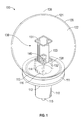
- FIG. 1 is a perspective view of a lighting device according to an embodiment of the present invention.
- FIG. 2 is an exploded perspective view of the lighting device illustrated in FIG. 1 .
- FIG. 3 is a perspective view of the lighting device illustrated in FIG. 1 showing contours of a thermally-conductive fluid flow from a filament structure of the lighting device with a fluid flow generator being operational.
- FIG. 4 is a schematic perspective view of a light emitting diode filament of the lighting device illustrated in FIG. 1 .
- FIG. 5 is a perspective view of a lighting device according to another embodiment of the present invention.
- FIG. 6 is a perspective view of a lighting device according to still another embodiment of the present invention.
- FIG. 7 is an exploded perspective view of the lighting device illustrated in FIG. 6 .
- FIG. 8 is a perspective view of a lighting device according to yet another embodiment of the present invention.
- a lighting device 100 may include a base 110 , a housing 111 , a driver circuit 116 , an optic 120 , a thermally-conductive fluid (shown in FIG. 3 only via contour lines), a light-emitting diode (LED) filament structure 130 , and a fluid flow generator 140 .
- the housing 111 may include a first end 112 and a second end 113 , and may further include an internal cavity 114 .
- the housing 111 may be fabricated of a thermally-conductive material, including, but not limited to, metals, metal alloys, ceramics, thermally-conductive polymers, and the like.
- the base 110 may include an electrical contact 115 .
- the housing 111 may be attached to the base 110 at the first end 112 .
- the driver circuit 116 may be positioned within the internal cavity 114 and may be positioned in electrical communication with the electrical contact 115 .
- the optic 120 may include an inner surface 121 which may define an optical chamber 122 . Furthermore, the optic 120 may be attached to the second end 113 of the housing 111 .
- the optic 120 may be fabricated of a transparent or translucent and thermally-conductive material.
- the thermally-conductive fluid and the LED filament structure 130 may be positioned within the optical chamber 122 . Additionally, the LED filament structure 130 may be in electrical communication with the driver circuit 116 .
- the fluid flow generator 140 may be positioned in fluid communication with the optical chamber 122 and may be in electrical communication with the driver circuit 116 .
- the fluid flow generator 140 may be adapted to generate a flow of the thermally-conductive fluid, and may be positioned such that the flow of thermally conductive fluid generated thereby is in the direction of the LED filament structure 130 .
- the fluid flow generator may be any type of device capable of generating a fluid flow as is known in the art, including, but not limited to, microblowers.
- the LED filament structure 130 may include an upper bracket 131 , a lower bracket 132 , and a plurality of LED filaments 133 .
- the plurality of LED filaments 133 may include an LED die 134 .
- the flow of thermally-conductive fluid, which may be generated by the fluid flow generator 140 may be directed towards at least one LED die 134 of the LED filament structure 130 .
- the plurality of LED filaments 133 may be positioned between the upper bracket 131 and the lower bracket 132 .
- FIGS. 1-3 show an upper bracket 131 and a lower bracket 132 , the present invention contemplates the use of one or more brackets.
- the LED filament structure 130 may further include a filament support 138 .
- the filament support 138 may be a separate structure attached to the LED filament structure 130 , or it may be integrally formed with the LED filament structure 130 .
- the filament support 138 may be a bracket or a combination of brackets attached to the housing 111 , the second end 112 , the LED filament structure 130 , the upper bracket 131 , the lower bracket 132 , the intermediate bracket 137 , the fluid flow generator 140 , and/or the flow redirection structure 150 .
- the filament support 138 may be attached to the second end 113 of the housing 111 and the lower bracket 132 .
- the filament support 138 may be four brackets. Those skilled in the art will appreciate that any number of brackets may be used. The present invention contemplates the use of one or more brackets. The present invention further contemplates any other number of configurations of the filament support 138 and any other number of placements of the filament support 138 to position the LED filament structure 130 as desired.
- the upper bracket 131 and the lower bracket 132 may be generally square in shape. Those skilled in the art will appreciate that the upper bracket 131 and the lower bracket 132 may be square, rectangular, circular, ovular, polygonal, or any combination thereof.
- the plurality of LED dies 134 may be arranged so as to define a light-emitting length 135 of the LED filament 133 .
- the flow of thermally-conductive fluid generated by the fluid flow generator 140 may be directed to be incident upon the entire light-emitting length 135 of the LED filament 133 .
- thermal energy generated by the LED dies 134 or any other heat-generating element of the LED filament structure 130 may be transferred to the thermally-conductive fluid.
- the thermally conductive fluid may have its temperature elevated from an initial temperature below the temperature of the LED dies 134 to a temperature at or near the present temperature of the LED dies 134 .
- the transfer of thermal energy will reduce the operating temperature of the LED dies 134 , thereby reducing the likelihood and/or extent of thermally-induced reduction in operating life of the LED dies 134 .
- the inner surface 121 of the optic 120 may be configured to maximize thermals transfer from the thermally-conductive fluid while still conforming to the geometric requirements of the standard bulb size that the lighting device 100 must conform to.
- the LED filament structure 130 and/or the LED filament 133 may also define a longitudinal axis 136 and the flow of thermally-conductive fluid may be in a direction generally perpendicular to the longitudinal axis 136 of the LED filament structure 130 and/or the LED filament 133 or generally parallel to the longitudinal axis 136 of the LED filament structure 130 and/or the LED filament 133 .
- Generally perpendicular to the longitudinal axis 136 is meant to include perpendicular to the longitudinal axis 136 and within 30 degrees of perpendicular to the longitudinal axis 136 .
- Generally parallel to the longitudinal axis 136 is meant to include parallel to the longitudinal axis 136 and within 30 degrees of parallel to the longitudinal axis 136 .
- the flow of thermally-conductive fluid may include any flow of thermally-conductive fluid that is directed along a length of the longitudinal axis 136 or along a perpendicular axis to the longitudinal axis 136 .
- the plurality of LED dies 134 may include one or more LED dies 134
- the lighting device 100 may include one or more LED filament structures 130
- the LED filament structures 130 may include one or more LED filaments 133 .
- the LED filament structure 130 may be formed of a thermally conductive material. Accordingly, the LED filament structure 130 may conduct thermal energy away from heat-generating elements thereof, such as the LED dies 134 . This may simultaneously reduce the operating temperature of the LED dies 134 while increasing the surface area from which the thermally-conductive fluid may absorb thermal energy, thereby increasing the thermal dissipation capacity of the LED filament structure 130 than if the LED filament structure 130 were formed of non-thermally conductive material. Additionally, in some embodiments, the LED filament structure 130 may be formed of electrically non-conductive material.
- the LED filament 133 may include a plurality of LED dies 134 . More particularly, the LED dies 134 may be provided by four LED dies 134 , but one, two, three, or any other number of LED dies is contemplated by the present invention, while still accomplishing the goals, features and objectives thereof. As shown in FIGS. 1-3 , the lighting device 100 may include the LED filament structure 130 with four LED filaments 133 , but one, two, three, or any other number is contemplated by the present invention while still accomplishing the goals, features and objectives thereof. In addition, the shape of the LED filaments 133 may be rectangular.
- the LED filaments 133 may be square, rectangular, circular, or have any other shaped as may be understood by those skilled in the art after having had the benefit of reading this disclosure.
- the LED filaments 133 may also be any combination of shapes and the LED filament structure 130 may include any number of LED filaments 133 attached at any number of angles.
- four LED filaments 131 may be attached to the upper bracket 131 and the lower bracket 132 .
- the fluid flow generator 140 may be positioned on the lower bracket 132 or the upper bracket 131 .
- the lighting device 100 may include any number of upper brackets 131 and/or lower brackets 132 .
- the optical chamber 122 and the internal cavity 114 may be in fluid communication with each other. Additionally, the thermally-conductive fluid may be positioned within both the optical chamber 122 and the internal cavity 114 .
- the lighting device 100 may further include a heat sink which may be positioned in thermal communication with the LED filament structure 130 and/or the driver circuit 116 .
- the base 110 and/or the housing 111 may be the heat sink. Additionally, the base 110 and/or the housing 111 may include a fin or a plurality of fins that may be the heat sink, may be a portion of the heat sink, or may be in addition to the heat sink. For example, and without limitation, the heat sink may include a plurality of fins connected to the bottom of the base 110 or the bottom of the housing 111 . Furthermore, any portion of the base 110 and/or the housing 111 may be the heat sink.
- the lighting device 100 may further comprise power circuitry (not shown).
- the power circuitry may be configured to electrically communicate with an electrical power supply associated with the lighting device 100 through, for example, and without limitation, the electrical contact 115 .
- Such an electrical power supply may be a power grid or a light socket.
- the power circuitry may be configured to receive electrical power from the electrical power supply and convert, condition, and otherwise alter the electrical power received from the electrical power supply for use by the various electrical elements of the lighting device 100 .
- the power circuitry may be configured to convert AC power to DC power.
- the power circuitry may be comprised by a control circuitry, such as the driver circuit 116 .
- the power circuitry may include the electrical contact 115 and/or the driver circuit 116 .
- the power circuitry may be configured to electrically communicate with the the LED filament structure 130 , the LED filament 133 , the plurality of LED dies 134 , and/or the fluid flow generator 140 .
- the fluid flow generator 140 may be positioned so as to generate a flow of the thermally-conductive fluid in the direction of the driver circuit 116 and/or the LED filament structure 130 and the fluid flow generator 140 may be positioned such that the driver circuit 116 may be intermediate to the fluid flow generator 140 and the LED filament structure 130 . Additionally, the fluid flow generator 140 may be positioned generally intermediate the driver circuit 116 and the LED filament structure 130 .
- the fluid flow generator 140 may be positioned to direct the flow of thermally conductive fluid towards the heat sink, the driver circuit 116 , and/or the LED filament structure 130 .
- the fluid flow generator 140 may be a microblower device.
- the lighting device 100 may include any number of fluid flow generators 140 .
- the thermally-conductive fluid may be air, helium, neon, and/or nitrogen. Those skilled in the art will appreciate that thermally-conductive fluid includes any type of fluid.
- the optical chamber 122 and the internal cavity 114 may combine to define an interior volume.
- the interior volume may be fluidically sealed from the environment surrounding the lighting device 100 .
- the optical chamber 122 and the internal cavity 114 may be fluidically sealed independently from one another.
- the optical chamber 122 and the internal cavity 114 may be configured so as not to be sealed. This may allow fluid to flow away from the lighting device 100 , thereby enhancing the cooling properties thereof.
- the fluid flow generator 140 may create a cyclical path of thermally-conductive fluid flow by directing the thermally-conductive fluid toward the apex of the inner surface 121 of the optic 120 .
- the thermally-conductive fluid may then be directed along the inner surface 121 of the optic 120 away from the apex and in a downward direction until the thermally-conductive fluid is directed to or near the nadir of the optical chamber 122 and/or to or near the fluid flow generator 140 where the cycle may repeat itself.
- the thermally-conductive fluid While traveling within a flow path adjacent to the optic 120 , the thermally-conductive fluid may transfer heat to the optic 120 which may then be dissipated into the environment surrounding the optic 120 .
- thermally-conductive fluid Once thermally-conductive fluid has flowed through a complete path, its temperature may be reduced from its initial temperature after having thermal energy transferred from the LED filament structure 130 thereto to below the present temperature of at least one of the LED dies 134 and the LED filament structure 130 .
- the fluid flow generator 140 may again direct the thermally-conductive fluid in the direction of the LED filament structure 130 , thereby completing and restarting the cyclical flow.
- the fluid flow generator 140 may also direct the thermally-conductive fluid in any number of directions and create any number of different cyclical flow paths within the optical chamber 122 and/or the internal cavity 114 .
- Each LED die 134 may emit light semi-hemispherically, hemispherically, or spherically. Each LED die 134 may emit light so that light is emitted in every direction away from a given point or a center of the optic or every direction except where the housing and the base will not permit the emission of light. In addition, those skilled in the art will appreciate that the position of the plurality of LED dies 134 and/or the LED filaments 133 within the LED filament structure 130 may emit light semi-hemispherically, hemispherically, or spherically.
- the position of the plurality of LED dies 134 and/or the LED filaments 133 within the LED filament structure 130 may cause light to be emitted in every direction away from a given point or a center of the optic or in every direction except where the housing 111 and/or the base 110 will not permit the emission of light.
- the LED filaments 133 , the upper bracket 131 , and/or the lower bracket 132 may be curved and/or flexible to emit light in more than a hemispherical direction, such as a spherical or semi-spherical direction.
- the LED filament structure 130 may position four LED filaments 133 such that each LED filament 133 is facing 90 degrees away from each adjacent LED filament 133 so that light is emitted generally omnidirectionally. More specifically, light may be emitted in a direction 360 degrees perpendicular to the longitudinal axis 136 and in a direction between parallel to the longitudinal axis 136 at or near the apex of the optic 120 and parallel or near parallel to the longitudinal axis 136 in a direction of the base 110 . An emission of light is created thereby that is spherical or semi-spherical, and at least more than hemispherical.
- the lighting device 100 ′ may illustratively include a flow redirection structure 160 ′ which may be configured to redirect fluid flow incident thereupon about at least a portion of the optical chamber 122 ′ and the flow of thermally-conductive fluid which may be generated by the fluid flow generator 140 ′ may be in the direction of the flow redirection structure 160 ′.
- the flow redirection structure 160 ′ may be positioned proximate to an apex of the optical chamber 122 ′ and the fluid flow generator 140 ′ may be positioned proximate to a nadir of the optical chamber 122 ′.
- the flow redirection structure 160 ′ may also be configured to redirect at least a portion of the fluid flow incident thereupon generally in the direction of the fluid flow generator 140 ′. Those skilled in the art will appreciate that the flow redirection structure 160 ′ may be positioned along any portion of the optic 120 ′ as desired.
- the flow redirection structure 160 ′ may be any shape desired, such as a pyramid or a cone and the sides of the flow redirection structure 160 ′ may be straight, curved, slanted, or a combination thereof.
- the flow redirection structure 160 ′ may be attached to the optic 120 ′ through the use of an adhesive, glue, latch, screw, bolt, nail, or any other attachment method as may be understood by those skilled in the art after having had the benefit of this disclosure.
- the flow redirection structure 160 ′ may also be an integral part of the optic 120 ′.
- any number of flow redirection structures 160 ′ may be used and any number of sizes of the flow redirection structure 160 ′ may be used.
- the other features of this embodiment of the lighting device 100 ′ are similar to those of the first embodiment of the lighting device 100 , are labeled with prime notation, and require no further discussion herein.
- the filament structure 130 ′′ may include the LED filaments 133 ′′ that have a curvature similar to that of the optic 120 ′′.
- the LED filaments 133 ′′ may have any curvature while still accomplishing the goals, features and advantages according to the present invention.
- the LED filament structure 130 may have a curvature that may be approximately equal to a curvature of the inner surface 121 of the optic 120 .
- the LED filament structure 130 may be configured to generally conform to the curvature of the optic 120 that may conform to a bulb configuration selected from the group consisting of A19, A15, A21, ST19, ST15, S21, S11, C7, G25, G20, PAR30, PAR20, BR30, BR40, and R20.
- the optic 120 may be formed into any shape desired.
- the remaining elements of this embodiment of the lighting device 100 ′′ are similar to those of the first embodiment of the lighting device 100 , are labeled with double prime notation, and require no further discussion herein.
- the LED filament structure 130 ′′′ may further include an intermediate bracket 137 ′′′.
- the intermediate bracket 137 ′′′ may be similar to the upper bracket 131 ′′′ and/or the lower bracket 132 ′′′.
- the intermediate bracket 137 ′′′ may also be a vertical structural component which may connect the upper bracket 131 ′′′ to 132 ′′′ and/or support the LED filaments 133 ′′′In addition, the intermediate bracket 137 ′′′ may be a combination of structural components similar to those described herein.
- the intermediate bracket 137 ′′′ may be a plurality of vertical structural components with a structural component similar to the upper bracket 131 ′′′ or the lower bracket 132 ′′′ located near a medial portion of the plurality of vertical structural components.
- the plurality of LED filaments 133 ′′′ may also be positioned on the intermediate bracket 137 ′′′ (or in contact with the intermediate bracket).
- the intermediate bracket 137 ′′′ may be square, rectangular, circular, ovular, polygonal, or any combination thereof.
- the fluid flow generator 140 ′′′ is illustrated as being carried by the lower bracket 132 ′′′, those skilled in the art will appreciate that the fluid flow generator may be carried by the intermediate bracket 137 ′′′, or by the upper bracket 131 ′′′.
- the intermediate bracket 137 ′′′ may be positioned between the upper bracket 131 ′′′ and the lower bracket 132 ′′′.
- the lighting device 100 ′′′ may include any number of intermediate brackets 137 ′′′.
- the intermediate bracket 137 ′′′ may be curved and/or flexible to allow light to be emitted in more than a hemispherical direction, such as a spherical or semi-spherical direction.
- the remaining elements of this embodiment of the lighting device 100 ′′′ are similar to those of the first embodiment of the lighting device 100 , are labeled with triple prime notation, and require no further discussion herein.
Landscapes
- Engineering & Computer Science (AREA)
- General Engineering & Computer Science (AREA)
- Microelectronics & Electronic Packaging (AREA)
- Physics & Mathematics (AREA)
- Optics & Photonics (AREA)
- Non-Portable Lighting Devices Or Systems Thereof (AREA)
- Arrangement Of Elements, Cooling, Sealing, Or The Like Of Lighting Devices (AREA)
Abstract
Description
Claims (21)
Priority Applications (1)
| Application Number | Priority Date | Filing Date | Title |
|---|---|---|---|
| US14/591,521 US9360202B2 (en) | 2011-05-13 | 2015-01-07 | System for actively cooling an LED filament and associated methods |
Applications Claiming Priority (6)
| Application Number | Priority Date | Filing Date | Title |
|---|---|---|---|
| US13/107,782 US20120285667A1 (en) | 2011-05-13 | 2011-05-13 | Sound baffling cooling system for led thermal management and associated methods |
| US13/461,333 US8608348B2 (en) | 2011-05-13 | 2012-05-01 | Sealed electrical device with cooling system and associated methods |
| US13/739,286 US8835945B2 (en) | 2013-01-11 | 2013-01-11 | Serially-connected light emitting diodes, methods of forming same, and luminaires containing same |
| US14/084,118 US9151482B2 (en) | 2011-05-13 | 2013-11-19 | Sealed electrical device with cooling system |
| US14/338,942 US9863588B2 (en) | 2013-01-11 | 2014-07-23 | Serially-connected light emitting diodes, methods of forming same, and luminaires containing same |
| US14/591,521 US9360202B2 (en) | 2011-05-13 | 2015-01-07 | System for actively cooling an LED filament and associated methods |
Related Parent Applications (2)
| Application Number | Title | Priority Date | Filing Date |
|---|---|---|---|
| US14/084,118 Continuation-In-Part US9151482B2 (en) | 2011-05-13 | 2013-11-19 | Sealed electrical device with cooling system |
| US14/338,942 Continuation-In-Part US9863588B2 (en) | 2011-05-13 | 2014-07-23 | Serially-connected light emitting diodes, methods of forming same, and luminaires containing same |
Related Child Applications (1)
| Application Number | Title | Priority Date | Filing Date |
|---|---|---|---|
| US13/461,333 Continuation-In-Part US8608348B2 (en) | 2011-05-13 | 2012-05-01 | Sealed electrical device with cooling system and associated methods |
Publications (2)
| Publication Number | Publication Date |
|---|---|
| US20150159853A1 US20150159853A1 (en) | 2015-06-11 |
| US9360202B2 true US9360202B2 (en) | 2016-06-07 |
Family
ID=53270759
Family Applications (1)
| Application Number | Title | Priority Date | Filing Date |
|---|---|---|---|
| US14/591,521 Expired - Fee Related US9360202B2 (en) | 2011-05-13 | 2015-01-07 | System for actively cooling an LED filament and associated methods |
Country Status (1)
| Country | Link |
|---|---|
| US (1) | US9360202B2 (en) |
Cited By (3)
| Publication number | Priority date | Publication date | Assignee | Title |
|---|---|---|---|---|
| RU188947U1 (en) * | 2018-05-23 | 2019-04-30 | Федеральное государственное бюджетное образовательное учреждение высшего образования "Томский государственный университет систем управления и радиоэлектроники" (ТУСУР) | LED LAMP |
| USD869746S1 (en) | 2018-03-30 | 2019-12-10 | Abl Ip Holding Llc | Light fixture base |
| US10718506B2 (en) | 2018-03-30 | 2020-07-21 | Abl Ip Holding Llc | Luminaire with adapter collar |
Families Citing this family (5)
| Publication number | Priority date | Publication date | Assignee | Title |
|---|---|---|---|---|
| US11997768B2 (en) * | 2014-09-28 | 2024-05-28 | Zhejiang Super Lighting Electric Appliance Co., Ltd | LED filament and LED light bulb |
| TWI567326B (en) * | 2015-07-17 | 2017-01-21 | 開發晶照明(廈門)有限公司 | LED Filament and LED Bulb with the Same |
| US20180100625A1 (en) * | 2016-10-12 | 2018-04-12 | Double Good Co. | Led light bulb and fabrication method thereof |
| RU2755678C1 (en) * | 2020-10-29 | 2021-09-20 | Олег Евгеньевич Петров | Led phyto-lamp with cooling system |
| US11746973B1 (en) | 2022-05-04 | 2023-09-05 | Barava, LLC | Hanging liquid lamp |
Citations (142)
| Publication number | Priority date | Publication date | Assignee | Title |
|---|---|---|---|---|
| US5057908A (en) | 1990-07-10 | 1991-10-15 | Iowa State University Research Foundation, Inc. | High power semiconductor device with integral heat sink |
| US5523878A (en) | 1994-06-30 | 1996-06-04 | Texas Instruments Incorporated | Self-assembled monolayer coating for micro-mechanical devices |
| US5704701A (en) | 1992-03-05 | 1998-01-06 | Rank Brimar Limited | Spatial light modulator system |
| US5997150A (en) | 1995-10-25 | 1999-12-07 | Texas Instruments Incorporated | Multiple emitter illuminator engine |
| US6140646A (en) | 1998-12-17 | 2000-10-31 | Sarnoff Corporation | Direct view infrared MEMS structure |
| US6290382B1 (en) | 1998-08-17 | 2001-09-18 | Ppt Vision, Inc. | Fiber bundle combiner and led illumination system and method |
| US6341876B1 (en) | 1997-02-19 | 2002-01-29 | Digital Projection Limited | Illumination system |
| US6356700B1 (en) | 1998-06-08 | 2002-03-12 | Karlheinz Strobl | Efficient light engine systems, components and methods of manufacture |
| US6358631B1 (en) | 1994-12-13 | 2002-03-19 | The Trustees Of Princeton University | Mixed vapor deposited films for electroluminescent devices |
| US6365270B2 (en) | 1994-12-13 | 2002-04-02 | The Trustees Of Princeton University | Organic light emitting devices |
| US20020151941A1 (en) | 2001-04-16 | 2002-10-17 | Shinichi Okawa | Medical illuminator, and medical apparatus having the medical illuminator |
| US6542671B1 (en) | 2001-12-12 | 2003-04-01 | Super Light Wave Corp. | Integrated 3-dimensional multi-layer thin-film optical couplers and attenuators |
| US6548956B2 (en) | 1994-12-13 | 2003-04-15 | The Trustees Of Princeton University | Transparent contacts for organic devices |
| US6561656B1 (en) | 2001-09-17 | 2003-05-13 | Mitsubishi Denki Kabushiki Kaisha | Illumination optical system with reflecting light valve |
| US6594090B2 (en) | 2001-08-27 | 2003-07-15 | Eastman Kodak Company | Laser projection display system |
| US6596134B2 (en) | 1994-12-13 | 2003-07-22 | The Trustees Of Princeton University | Method of fabricating transparent contacts for organic devices |
| WO2003073518A1 (en) | 2002-02-27 | 2003-09-04 | Midwest Research Institute | Voltage-matched, monolithic, multi-band-gap devices |
| US20040008525A1 (en) * | 2002-07-09 | 2004-01-15 | Hakuyo Denkyuu Kabushiki Kaisha: Fuso Denki Kougyou Kabushiki Kaisha | LED electric bulb |
| US6733135B2 (en) | 2002-04-02 | 2004-05-11 | Samsung Electronics Co., Ltd. | Image projection apparatus |
| US6767111B1 (en) | 2003-02-26 | 2004-07-27 | Kuo-Yen Lai | Projection light source from light emitting diodes |
| US6817735B2 (en) | 2001-05-24 | 2004-11-16 | Matsushita Electric Industrial Co., Ltd. | Illumination light source |
| US6870523B1 (en) | 2000-06-07 | 2005-03-22 | Genoa Color Technologies | Device, system and method for electronic true color display |
| US6871982B2 (en) | 2003-01-24 | 2005-03-29 | Digital Optics International Corporation | High-density illumination system |
| US6893140B2 (en) | 2002-12-13 | 2005-05-17 | W. T. Storey, Inc. | Flashlight |
| US20050156501A1 (en) * | 2005-02-24 | 2005-07-21 | Osram Sylvania Inc. | Multi-segment filament high output halogen lamp |
| US6945672B2 (en) | 2002-08-30 | 2005-09-20 | Gelcore Llc | LED planar light source and low-profile headlight constructed therewith |
| US6964501B2 (en) | 2002-12-24 | 2005-11-15 | Altman Stage Lighting Co., Ltd. | Peltier-cooled LED lighting assembly |
| US6967761B2 (en) | 2000-10-31 | 2005-11-22 | Microsoft Corporation | Microelectrical mechanical structure (MEMS) optical modulator and optical display system |
| US6974713B2 (en) | 2000-08-11 | 2005-12-13 | Reflectivity, Inc. | Micromirrors with mechanisms for enhancing coupling of the micromirrors with electrostatic fields |
| US7042623B1 (en) | 2004-10-19 | 2006-05-09 | Reflectivity, Inc | Light blocking layers in MEMS packages |
| US7072096B2 (en) | 2001-12-14 | 2006-07-04 | Digital Optics International, Corporation | Uniform illumination system |
| US7070281B2 (en) | 2002-12-04 | 2006-07-04 | Nec Viewtechnology, Ltd. | Light source device and projection display |
| US7075707B1 (en) | 1998-11-25 | 2006-07-11 | Research Foundation Of The University Of Central Florida, Incorporated | Substrate design for optimized performance of up-conversion phosphors utilizing proper thermal management |
| US7083304B2 (en) | 2003-08-01 | 2006-08-01 | Illumination Management Solutions, Inc. | Apparatus and method of using light sources of differing wavelengths in an unitized beam |
| US7178941B2 (en) | 2003-05-05 | 2007-02-20 | Color Kinetics Incorporated | Lighting methods and systems |
| US20070041167A1 (en) | 2005-08-19 | 2007-02-22 | Dai-Ichi Shomei Co., Ltd. | Medical lighting apparatus |
| US7184201B2 (en) | 2004-11-02 | 2007-02-27 | Texas Instruments Incorporated | Digital micro-mirror device having improved contrast and method for the same |
| US7246923B2 (en) | 2004-02-11 | 2007-07-24 | 3M Innovative Properties Company | Reshaping light source modules and illumination systems using the same |
| US7255469B2 (en) | 2004-06-30 | 2007-08-14 | 3M Innovative Properties Company | Phosphor based illumination system having a light guide and an interference reflector |
| US7261453B2 (en) | 2005-01-25 | 2007-08-28 | Morejon Israel J | LED polarizing optics for color illumination system and method of using same |
| US7285801B2 (en) | 2004-04-02 | 2007-10-23 | Lumination, Llc | LED with series-connected monolithically integrated mesas |
| US7289090B2 (en) | 2003-12-10 | 2007-10-30 | Texas Instruments Incorporated | Pulsed LED scan-ring array for boosting display system lumens |
| US7300177B2 (en) | 2004-02-11 | 2007-11-27 | 3M Innovative Properties | Illumination system having a plurality of light source modules disposed in an array with a non-radially symmetrical aperture |
| US7303291B2 (en) | 2004-03-31 | 2007-12-04 | Sanyo Electric Co., Ltd. | Illumination apparatus and video projection display system |
| US7306352B2 (en) | 2004-10-19 | 2007-12-11 | Samsung Electronics Co., Ltd. | Illuminator |
| US7325956B2 (en) | 2005-01-25 | 2008-02-05 | Jabil Circuit, Inc. | Light-emitting diode (LED) illumination system for a digital micro-mirror device (DMD) and method of providing same |
| US7342658B2 (en) | 2005-12-28 | 2008-03-11 | Eastman Kodak Company | Programmable spectral imaging system |
| US7344280B2 (en) | 2002-09-30 | 2008-03-18 | Teledyne Lighting And Display Products, Inc. | Illuminator assembly |
| US7344279B2 (en) | 2003-12-11 | 2008-03-18 | Philips Solid-State Lighting Solutions, Inc. | Thermal management methods and apparatus for lighting devices |
| US7349095B2 (en) | 2005-05-19 | 2008-03-25 | Casio Computer Co., Ltd. | Light source apparatus and projection apparatus |
| US7353859B2 (en) | 2004-11-24 | 2008-04-08 | General Electric Company | Heat sink with microchannel cooling for power devices |
| US7382091B2 (en) | 2005-07-27 | 2008-06-03 | Lung-Chien Chen | White light emitting diode using phosphor excitation |
| US7382632B2 (en) | 2005-04-06 | 2008-06-03 | International Business Machines Corporation | Computer acoustic baffle and cable management system |
| EP1950491A1 (en) | 2007-01-26 | 2008-07-30 | Piper Lux S.r.l. | LED spotlight |
| WO2008091837A2 (en) | 2007-01-22 | 2008-07-31 | Cree Led Lighting Solutions, Inc. | Fault tolerant light emitters, systems incorporating fault tolerant light emitters and methods of fabricating fault tolerant light emitters |
| US7427146B2 (en) | 2004-02-11 | 2008-09-23 | 3M Innovative Properties Company | Light-collecting illumination system |
| US20080232116A1 (en) | 2007-03-22 | 2008-09-25 | Led Folio Corporation | Lighting device for a recessed light fixture |
| US7429983B2 (en) | 2005-11-01 | 2008-09-30 | Cheetah Omni, Llc | Packet-based digital display system |
| US7434946B2 (en) | 2005-06-17 | 2008-10-14 | Texas Instruments Incorporated | Illumination system with integrated heat dissipation device for use in display systems employing spatial light modulators |
| US7438443B2 (en) | 2003-09-19 | 2008-10-21 | Ricoh Company, Limited | Lighting device, image-reading device, color-document reading apparatus, image-forming apparatus, projection apparatus |
| WO2008137732A1 (en) | 2007-05-04 | 2008-11-13 | Koninklijke Philips Electronics N V | Led-based fixtures and related methods for thermal management |
| US7476016B2 (en) | 2005-06-28 | 2009-01-13 | Seiko Instruments Inc. | Illuminating device and display device including the same |
| WO2009040703A2 (en) | 2007-09-27 | 2009-04-02 | Philips Intellectual Property & Standards Gmbh | Lighting device and method of cooling a lighting device |
| US7530708B2 (en) | 2004-10-04 | 2009-05-12 | Lg Electronics Inc. | Surface emitting light source and projection display device using the same |
| US7537347B2 (en) | 2005-11-29 | 2009-05-26 | Texas Instruments Incorporated | Method of combining dispersed light sources for projection display |
| US7540616B2 (en) | 2005-12-23 | 2009-06-02 | 3M Innovative Properties Company | Polarized, multicolor LED-based illumination source |
| US20090141506A1 (en) | 2007-12-03 | 2009-06-04 | Shih-Chi Lan | Illumination Device for Kitchen Hood |
| US7556406B2 (en) | 2003-03-31 | 2009-07-07 | Lumination Llc | Led light with active cooling |
| US7598686B2 (en) | 1997-12-17 | 2009-10-06 | Philips Solid-State Lighting Solutions, Inc. | Organic light emitting diode methods and apparatus |
| US7605971B2 (en) | 2003-11-01 | 2009-10-20 | Silicon Quest Kabushiki-Kaisha | Plurality of hidden hinges for mircromirror device |
| US20090268468A1 (en) | 2008-04-23 | 2009-10-29 | Foxconn Technology Co., Ltd. | Led illuminating device and light engine thereof |
| US7626755B2 (en) | 2007-01-31 | 2009-12-01 | Panasonic Corporation | Wavelength converter and two-dimensional image display device |
| US20100027276A1 (en) * | 2008-07-30 | 2010-02-04 | Alexander Kornitz | Thermal control system for a light-emitting diode fixture |
| US20100027270A1 (en) * | 2008-08-04 | 2010-02-04 | Huang Yao Hui | Safe and high-brightness led lamp |
| US7670021B2 (en) | 2007-09-27 | 2010-03-02 | Enertron, Inc. | Method and apparatus for thermally effective trim for light fixture |
| US7677736B2 (en) | 2004-02-27 | 2010-03-16 | Panasonic Corporation | Illumination light source and two-dimensional image display using same |
| US7684007B2 (en) | 2004-08-23 | 2010-03-23 | The Boeing Company | Adaptive and interactive scene illumination |
| US20100091486A1 (en) * | 2008-10-11 | 2010-04-15 | Jiahn-Chang Wu | Internal circulation mechanism for an air-tight led lamp |
| US7703943B2 (en) | 2007-05-07 | 2010-04-27 | Intematix Corporation | Color tunable light source |
| US7709811B2 (en) | 2007-07-03 | 2010-05-04 | Conner Arlie R | Light emitting diode illumination system |
| US7719766B2 (en) | 2007-06-20 | 2010-05-18 | Texas Instruments Incorporated | Illumination source and method therefor |
| US20100155766A1 (en) | 2008-12-22 | 2010-06-24 | Foxconn Technology Co., Ltd. | Light emitting diode and method for manufacturing the same |
| US7766490B2 (en) | 2006-12-13 | 2010-08-03 | Philips Lumileds Lighting Company, Llc | Multi-color primary light generation in a projection system using LEDs |
| US7771085B2 (en) | 2007-01-16 | 2010-08-10 | Steven Kim | Circular LED panel light |
| US20100207502A1 (en) * | 2009-02-17 | 2010-08-19 | Densen Cao | LED Light Bulbs for Space Lighting |
| US20100213881A1 (en) | 2009-02-23 | 2010-08-26 | Ushio Denki Kabushiki Kaisha | Light source apparatus |
| US7819556B2 (en) | 2006-12-22 | 2010-10-26 | Nuventix, Inc. | Thermal management system for LED array |
| US7835056B2 (en) | 2005-05-13 | 2010-11-16 | Her Majesty the Queen in Right of Canada, as represented by Institut National d'Optique | Image projector with flexible reflective analog modulator |
| US7832878B2 (en) | 2006-03-06 | 2010-11-16 | Innovations In Optics, Inc. | Light emitting diode projection system |
| US7834867B2 (en) | 2006-04-11 | 2010-11-16 | Microvision, Inc. | Integrated photonics module and devices using integrated photonics modules |
| US20100301728A1 (en) | 2009-06-02 | 2010-12-02 | Bridgelux, Inc. | Light source having a refractive element |
| US7845823B2 (en) | 1997-08-26 | 2010-12-07 | Philips Solid-State Lighting Solutions, Inc. | Controlled lighting methods and apparatus |
| US20100315320A1 (en) | 2007-12-07 | 2010-12-16 | Sony Corporation | Light source device and display device |
| US20100321641A1 (en) | 2008-02-08 | 2010-12-23 | Koninklijke Philips Electronics N.V. | Light module device |
| US7884377B2 (en) | 2007-03-21 | 2011-02-08 | Samsung Led Co., Ltd. | Light emitting device, method of manufacturing the same and monolithic light emitting diode array |
| US7883241B2 (en) | 2008-05-06 | 2011-02-08 | Asustek Computer Inc. | Electronic device and heat dissipation unit thereof |
| US7889430B2 (en) | 2006-05-09 | 2011-02-15 | Ostendo Technologies, Inc. | LED-based high efficiency illumination systems for use in projection systems |
| US7906722B2 (en) | 2005-04-19 | 2011-03-15 | Palo Alto Research Center Incorporated | Concentrating solar collector with solid optical element |
| US7910395B2 (en) | 2006-09-13 | 2011-03-22 | Helio Optoelectronics Corporation | LED structure |
| US20110080732A1 (en) | 2009-10-02 | 2011-04-07 | Chen ying-zhong | Illumination device |
| US7928565B2 (en) | 2004-06-15 | 2011-04-19 | International Business Machines Corporation | Semiconductor device with a high thermal dissipation efficiency |
| US7976205B2 (en) | 2005-08-31 | 2011-07-12 | Osram Opto Semiconductors Gmbh | Light-emitting module, particularly for use in an optical projection apparatus |
| US20110205738A1 (en) | 2010-02-25 | 2011-08-25 | Lunera Lighting Inc. | Troffer-style light fixture with cross-lighting |
| US8008680B2 (en) | 2007-09-07 | 2011-08-30 | Epistar Corporation | Light-emitting diode device and manufacturing method thereof |
| US8047660B2 (en) | 2005-09-13 | 2011-11-01 | Texas Instruments Incorporated | Projection system and method including spatial light modulator and compact diffractive optics |
| US8061857B2 (en) | 2008-11-21 | 2011-11-22 | Hong Kong Applied Science And Technology Research Institute Co. Ltd. | LED light shaping device and illumination system |
| US8070302B2 (en) | 2005-05-10 | 2011-12-06 | Iwasaki Electric Co., Ltd. | Laminate type light-emitting diode device, and reflection type light-emitting diode unit |
| US8083364B2 (en) | 2008-12-29 | 2011-12-27 | Osram Sylvania Inc. | Remote phosphor LED illumination system |
| US20120002411A1 (en) | 2009-01-21 | 2012-01-05 | Cooper Technologies Company | Light Emitting Diode Troffer |
| US8096668B2 (en) | 2008-01-16 | 2012-01-17 | Abu-Ageel Nayef M | Illumination systems utilizing wavelength conversion materials |
| US20120044642A1 (en) * | 2010-08-23 | 2012-02-23 | Rodriguez Edward T | Cooling Methodology for High Brightness Light Emitting Diodes |
| US20120051041A1 (en) | 2010-08-31 | 2012-03-01 | Cree, Inc. | Troffer-Style Fixture |
| WO2012031533A1 (en) | 2010-09-08 | 2012-03-15 | 浙江锐迪生光电有限公司 | Led lamp bulb and led lighting bar capable of emitting light over 4π |
| US20120106144A1 (en) | 2010-10-28 | 2012-05-03 | Hon Hai Precision Industry Co., Ltd. | Led tube lamp |
| US20120120659A1 (en) | 2010-11-16 | 2012-05-17 | Lopez Peter E | Board assemblies, light emitting device assemblies, and methods of making the same |
| US8193018B2 (en) | 2008-01-10 | 2012-06-05 | Global Oled Technology Llc | Patterning method for light-emitting devices |
| US8201968B2 (en) | 2009-10-05 | 2012-06-19 | Lighting Science Group Corporation | Low profile light |
| US20120201034A1 (en) | 2009-09-25 | 2012-08-09 | Chia-Mao Li | Wide-Range Reflective Structure |
| US20120235181A1 (en) | 2010-12-27 | 2012-09-20 | Panasonic Corporation | Light-emitting device and lamp |
| US8272763B1 (en) | 2009-10-02 | 2012-09-25 | Genesis LED Solutions | LED luminaire |
| US20120262902A1 (en) | 2011-04-18 | 2012-10-18 | Cree, Inc. | Led luminaire including a thin phosphor layer applied to a remote reflector |
| US8297798B1 (en) | 2010-04-16 | 2012-10-30 | Cooper Technologies Company | LED lighting fixture |
| US20120285667A1 (en) | 2011-05-13 | 2012-11-15 | Lighting Science Group Corporation | Sound baffling cooling system for led thermal management and associated methods |
| WO2012158607A1 (en) | 2011-05-13 | 2012-11-22 | Lighting Science Group Corporation | Sound baffling cooling system for led thermal management and associated methods |
| US8319408B1 (en) | 2011-05-23 | 2012-11-27 | Sunonwealth Electric Machine Industry Co., Ltd. | LED lamp with simplified structure |
| US8337063B2 (en) | 2009-08-25 | 2012-12-25 | Stanley Electric Co., Ltd. | Vehicle light |
| US8337066B2 (en) | 2010-09-30 | 2012-12-25 | Chunghwa Picture Tubes, Ltd. | Backlight module |
| US20120327650A1 (en) | 2011-06-27 | 2012-12-27 | Cree, Inc. | Direct and back view led lighting system |
| US20130021792A1 (en) | 2011-07-24 | 2013-01-24 | Cree, Inc. | Modular indirect suspended/ceiling mount fixture |
| US20130044490A1 (en) * | 2011-08-17 | 2013-02-21 | Asia Vital Components Co., Ltd. | Heat dissipation structure for led lighting |
| US20130050979A1 (en) | 2011-08-26 | 2013-02-28 | Antony P. Van de Ven | Reduced phosphor lighting devices |
| US8408748B2 (en) * | 2008-01-10 | 2013-04-02 | Goeken Group Corp. | LED lamp replacement of low power incandescent lamp |
| US8419249B2 (en) | 2009-04-15 | 2013-04-16 | Stanley Electric Co., Ltd. | Liquid-cooled LED lighting device |
| US8427590B2 (en) | 2009-05-29 | 2013-04-23 | Soraa, Inc. | Laser based display method and system |
| US8461599B2 (en) | 2010-12-01 | 2013-06-11 | Hon Hai Precision Industry Co., Ltd. | Light emitting diode with a stable color temperature |
| US20130223055A1 (en) | 2009-10-05 | 2013-08-29 | Lighting Science Group Corporation | Low profile light having elongated reflector and associated methods |
| US8531126B2 (en) | 2008-02-13 | 2013-09-10 | Canon Components, Inc. | White light emitting apparatus and line illuminator using the same in image reading apparatus |
| US8585242B2 (en) | 2010-02-04 | 2013-11-19 | Sternberg Lanterns, Inc. | Lighting system with light-emitting diodes and securing structure |
| US8672518B2 (en) | 2009-10-05 | 2014-03-18 | Lighting Science Group Corporation | Low profile light and accessory kit for the same |
| US8735189B2 (en) | 2012-05-17 | 2014-05-27 | Starlite LED Inc | Flip light emitting diode chip and method of fabricating the same |
| US8835945B2 (en) | 2013-01-11 | 2014-09-16 | Lighting Science Group Corporation | Serially-connected light emitting diodes, methods of forming same, and luminaires containing same |
| US20140268827A1 (en) * | 2011-06-08 | 2014-09-18 | Gerhard Schwarz | Cooling System and LED- Based Light Comprising Same |
-
2015
- 2015-01-07 US US14/591,521 patent/US9360202B2/en not_active Expired - Fee Related
Patent Citations (153)
| Publication number | Priority date | Publication date | Assignee | Title |
|---|---|---|---|---|
| US5057908A (en) | 1990-07-10 | 1991-10-15 | Iowa State University Research Foundation, Inc. | High power semiconductor device with integral heat sink |
| US5704701A (en) | 1992-03-05 | 1998-01-06 | Rank Brimar Limited | Spatial light modulator system |
| US5523878A (en) | 1994-06-30 | 1996-06-04 | Texas Instruments Incorporated | Self-assembled monolayer coating for micro-mechanical devices |
| US6596134B2 (en) | 1994-12-13 | 2003-07-22 | The Trustees Of Princeton University | Method of fabricating transparent contacts for organic devices |
| US7714504B2 (en) | 1994-12-13 | 2010-05-11 | The Trustees Of Princeton University | Multicolor organic electroluminescent device formed of vertically stacked light emitting devices |
| US8324803B2 (en) | 1994-12-13 | 2012-12-04 | The Trustees Of Princeton University | Transparent contacts for organic devices |
| US7173369B2 (en) | 1994-12-13 | 2007-02-06 | The Trustees Of Princeton University | Transparent contacts for organic devices |
| US6548956B2 (en) | 1994-12-13 | 2003-04-15 | The Trustees Of Princeton University | Transparent contacts for organic devices |
| US6358631B1 (en) | 1994-12-13 | 2002-03-19 | The Trustees Of Princeton University | Mixed vapor deposited films for electroluminescent devices |
| US6365270B2 (en) | 1994-12-13 | 2002-04-02 | The Trustees Of Princeton University | Organic light emitting devices |
| US5997150A (en) | 1995-10-25 | 1999-12-07 | Texas Instruments Incorporated | Multiple emitter illuminator engine |
| US6341876B1 (en) | 1997-02-19 | 2002-01-29 | Digital Projection Limited | Illumination system |
| US7845823B2 (en) | 1997-08-26 | 2010-12-07 | Philips Solid-State Lighting Solutions, Inc. | Controlled lighting methods and apparatus |
| US7598686B2 (en) | 1997-12-17 | 2009-10-06 | Philips Solid-State Lighting Solutions, Inc. | Organic light emitting diode methods and apparatus |
| US6356700B1 (en) | 1998-06-08 | 2002-03-12 | Karlheinz Strobl | Efficient light engine systems, components and methods of manufacture |
| US6290382B1 (en) | 1998-08-17 | 2001-09-18 | Ppt Vision, Inc. | Fiber bundle combiner and led illumination system and method |
| US7075707B1 (en) | 1998-11-25 | 2006-07-11 | Research Foundation Of The University Of Central Florida, Incorporated | Substrate design for optimized performance of up-conversion phosphors utilizing proper thermal management |
| US6140646A (en) | 1998-12-17 | 2000-10-31 | Sarnoff Corporation | Direct view infrared MEMS structure |
| US6870523B1 (en) | 2000-06-07 | 2005-03-22 | Genoa Color Technologies | Device, system and method for electronic true color display |
| US6974713B2 (en) | 2000-08-11 | 2005-12-13 | Reflectivity, Inc. | Micromirrors with mechanisms for enhancing coupling of the micromirrors with electrostatic fields |
| US6967761B2 (en) | 2000-10-31 | 2005-11-22 | Microsoft Corporation | Microelectrical mechanical structure (MEMS) optical modulator and optical display system |
| US20050033119A1 (en) | 2001-04-16 | 2005-02-10 | J. Morita Manufacturing Corporation | Medical illuminator, and medical apparatus having the medical illuminator |
| US20020151941A1 (en) | 2001-04-16 | 2002-10-17 | Shinichi Okawa | Medical illuminator, and medical apparatus having the medical illuminator |
| US6817735B2 (en) | 2001-05-24 | 2004-11-16 | Matsushita Electric Industrial Co., Ltd. | Illumination light source |
| US6594090B2 (en) | 2001-08-27 | 2003-07-15 | Eastman Kodak Company | Laser projection display system |
| US6561656B1 (en) | 2001-09-17 | 2003-05-13 | Mitsubishi Denki Kabushiki Kaisha | Illumination optical system with reflecting light valve |
| US6542671B1 (en) | 2001-12-12 | 2003-04-01 | Super Light Wave Corp. | Integrated 3-dimensional multi-layer thin-film optical couplers and attenuators |
| US7400439B2 (en) | 2001-12-14 | 2008-07-15 | Digital Optics International Corporation | Uniform illumination system |
| US7072096B2 (en) | 2001-12-14 | 2006-07-04 | Digital Optics International, Corporation | Uniform illumination system |
| WO2003073518A1 (en) | 2002-02-27 | 2003-09-04 | Midwest Research Institute | Voltage-matched, monolithic, multi-band-gap devices |
| US6733135B2 (en) | 2002-04-02 | 2004-05-11 | Samsung Electronics Co., Ltd. | Image projection apparatus |
| US20040008525A1 (en) * | 2002-07-09 | 2004-01-15 | Hakuyo Denkyuu Kabushiki Kaisha: Fuso Denki Kougyou Kabushiki Kaisha | LED electric bulb |
| US6945672B2 (en) | 2002-08-30 | 2005-09-20 | Gelcore Llc | LED planar light source and low-profile headlight constructed therewith |
| US7344280B2 (en) | 2002-09-30 | 2008-03-18 | Teledyne Lighting And Display Products, Inc. | Illuminator assembly |
| US7070281B2 (en) | 2002-12-04 | 2006-07-04 | Nec Viewtechnology, Ltd. | Light source device and projection display |
| US6893140B2 (en) | 2002-12-13 | 2005-05-17 | W. T. Storey, Inc. | Flashlight |
| US6964501B2 (en) | 2002-12-24 | 2005-11-15 | Altman Stage Lighting Co., Ltd. | Peltier-cooled LED lighting assembly |
| US6871982B2 (en) | 2003-01-24 | 2005-03-29 | Digital Optics International Corporation | High-density illumination system |
| US7520642B2 (en) | 2003-01-24 | 2009-04-21 | Digital Optics International Corporation | High-density illumination system |
| US6767111B1 (en) | 2003-02-26 | 2004-07-27 | Kuo-Yen Lai | Projection light source from light emitting diodes |
| US7556406B2 (en) | 2003-03-31 | 2009-07-07 | Lumination Llc | Led light with active cooling |
| US7178941B2 (en) | 2003-05-05 | 2007-02-20 | Color Kinetics Incorporated | Lighting methods and systems |
| US7083304B2 (en) | 2003-08-01 | 2006-08-01 | Illumination Management Solutions, Inc. | Apparatus and method of using light sources of differing wavelengths in an unitized beam |
| US7438443B2 (en) | 2003-09-19 | 2008-10-21 | Ricoh Company, Limited | Lighting device, image-reading device, color-document reading apparatus, image-forming apparatus, projection apparatus |
| US7605971B2 (en) | 2003-11-01 | 2009-10-20 | Silicon Quest Kabushiki-Kaisha | Plurality of hidden hinges for mircromirror device |
| US7289090B2 (en) | 2003-12-10 | 2007-10-30 | Texas Instruments Incorporated | Pulsed LED scan-ring array for boosting display system lumens |
| US7344279B2 (en) | 2003-12-11 | 2008-03-18 | Philips Solid-State Lighting Solutions, Inc. | Thermal management methods and apparatus for lighting devices |
| US7427146B2 (en) | 2004-02-11 | 2008-09-23 | 3M Innovative Properties Company | Light-collecting illumination system |
| US7300177B2 (en) | 2004-02-11 | 2007-11-27 | 3M Innovative Properties | Illumination system having a plurality of light source modules disposed in an array with a non-radially symmetrical aperture |
| US7246923B2 (en) | 2004-02-11 | 2007-07-24 | 3M Innovative Properties Company | Reshaping light source modules and illumination systems using the same |
| US7677736B2 (en) | 2004-02-27 | 2010-03-16 | Panasonic Corporation | Illumination light source and two-dimensional image display using same |
| US7303291B2 (en) | 2004-03-31 | 2007-12-04 | Sanyo Electric Co., Ltd. | Illumination apparatus and video projection display system |
| US7285801B2 (en) | 2004-04-02 | 2007-10-23 | Lumination, Llc | LED with series-connected monolithically integrated mesas |
| US7928565B2 (en) | 2004-06-15 | 2011-04-19 | International Business Machines Corporation | Semiconductor device with a high thermal dissipation efficiency |
| US7255469B2 (en) | 2004-06-30 | 2007-08-14 | 3M Innovative Properties Company | Phosphor based illumination system having a light guide and an interference reflector |
| US7684007B2 (en) | 2004-08-23 | 2010-03-23 | The Boeing Company | Adaptive and interactive scene illumination |
| US7530708B2 (en) | 2004-10-04 | 2009-05-12 | Lg Electronics Inc. | Surface emitting light source and projection display device using the same |
| US7306352B2 (en) | 2004-10-19 | 2007-12-11 | Samsung Electronics Co., Ltd. | Illuminator |
| US7042623B1 (en) | 2004-10-19 | 2006-05-09 | Reflectivity, Inc | Light blocking layers in MEMS packages |
| US7184201B2 (en) | 2004-11-02 | 2007-02-27 | Texas Instruments Incorporated | Digital micro-mirror device having improved contrast and method for the same |
| US7353859B2 (en) | 2004-11-24 | 2008-04-08 | General Electric Company | Heat sink with microchannel cooling for power devices |
| US7325956B2 (en) | 2005-01-25 | 2008-02-05 | Jabil Circuit, Inc. | Light-emitting diode (LED) illumination system for a digital micro-mirror device (DMD) and method of providing same |
| US7261453B2 (en) | 2005-01-25 | 2007-08-28 | Morejon Israel J | LED polarizing optics for color illumination system and method of using same |
| US20050156501A1 (en) * | 2005-02-24 | 2005-07-21 | Osram Sylvania Inc. | Multi-segment filament high output halogen lamp |
| US7382632B2 (en) | 2005-04-06 | 2008-06-03 | International Business Machines Corporation | Computer acoustic baffle and cable management system |
| US7906722B2 (en) | 2005-04-19 | 2011-03-15 | Palo Alto Research Center Incorporated | Concentrating solar collector with solid optical element |
| US8070302B2 (en) | 2005-05-10 | 2011-12-06 | Iwasaki Electric Co., Ltd. | Laminate type light-emitting diode device, and reflection type light-emitting diode unit |
| US7835056B2 (en) | 2005-05-13 | 2010-11-16 | Her Majesty the Queen in Right of Canada, as represented by Institut National d'Optique | Image projector with flexible reflective analog modulator |
| US7349095B2 (en) | 2005-05-19 | 2008-03-25 | Casio Computer Co., Ltd. | Light source apparatus and projection apparatus |
| US7434946B2 (en) | 2005-06-17 | 2008-10-14 | Texas Instruments Incorporated | Illumination system with integrated heat dissipation device for use in display systems employing spatial light modulators |
| US7476016B2 (en) | 2005-06-28 | 2009-01-13 | Seiko Instruments Inc. | Illuminating device and display device including the same |
| US7382091B2 (en) | 2005-07-27 | 2008-06-03 | Lung-Chien Chen | White light emitting diode using phosphor excitation |
| US20070041167A1 (en) | 2005-08-19 | 2007-02-22 | Dai-Ichi Shomei Co., Ltd. | Medical lighting apparatus |
| US7976205B2 (en) | 2005-08-31 | 2011-07-12 | Osram Opto Semiconductors Gmbh | Light-emitting module, particularly for use in an optical projection apparatus |
| US8047660B2 (en) | 2005-09-13 | 2011-11-01 | Texas Instruments Incorporated | Projection system and method including spatial light modulator and compact diffractive optics |
| US7429983B2 (en) | 2005-11-01 | 2008-09-30 | Cheetah Omni, Llc | Packet-based digital display system |
| US7537347B2 (en) | 2005-11-29 | 2009-05-26 | Texas Instruments Incorporated | Method of combining dispersed light sources for projection display |
| US7540616B2 (en) | 2005-12-23 | 2009-06-02 | 3M Innovative Properties Company | Polarized, multicolor LED-based illumination source |
| US7342658B2 (en) | 2005-12-28 | 2008-03-11 | Eastman Kodak Company | Programmable spectral imaging system |
| US7832878B2 (en) | 2006-03-06 | 2010-11-16 | Innovations In Optics, Inc. | Light emitting diode projection system |
| US7834867B2 (en) | 2006-04-11 | 2010-11-16 | Microvision, Inc. | Integrated photonics module and devices using integrated photonics modules |
| US7889430B2 (en) | 2006-05-09 | 2011-02-15 | Ostendo Technologies, Inc. | LED-based high efficiency illumination systems for use in projection systems |
| US7910395B2 (en) | 2006-09-13 | 2011-03-22 | Helio Optoelectronics Corporation | LED structure |
| US7766490B2 (en) | 2006-12-13 | 2010-08-03 | Philips Lumileds Lighting Company, Llc | Multi-color primary light generation in a projection system using LEDs |
| US7819556B2 (en) | 2006-12-22 | 2010-10-26 | Nuventix, Inc. | Thermal management system for LED array |
| US7771085B2 (en) | 2007-01-16 | 2010-08-10 | Steven Kim | Circular LED panel light |
| WO2008091837A2 (en) | 2007-01-22 | 2008-07-31 | Cree Led Lighting Solutions, Inc. | Fault tolerant light emitters, systems incorporating fault tolerant light emitters and methods of fabricating fault tolerant light emitters |
| EP1950491A1 (en) | 2007-01-26 | 2008-07-30 | Piper Lux S.r.l. | LED spotlight |
| US7626755B2 (en) | 2007-01-31 | 2009-12-01 | Panasonic Corporation | Wavelength converter and two-dimensional image display device |
| US7884377B2 (en) | 2007-03-21 | 2011-02-08 | Samsung Led Co., Ltd. | Light emitting device, method of manufacturing the same and monolithic light emitting diode array |
| US20080232116A1 (en) | 2007-03-22 | 2008-09-25 | Led Folio Corporation | Lighting device for a recessed light fixture |
| US7828465B2 (en) | 2007-05-04 | 2010-11-09 | Koninlijke Philips Electronis N.V. | LED-based fixtures and related methods for thermal management |
| WO2008137732A1 (en) | 2007-05-04 | 2008-11-13 | Koninklijke Philips Electronics N V | Led-based fixtures and related methods for thermal management |
| US7703943B2 (en) | 2007-05-07 | 2010-04-27 | Intematix Corporation | Color tunable light source |
| US7719766B2 (en) | 2007-06-20 | 2010-05-18 | Texas Instruments Incorporated | Illumination source and method therefor |
| US7709811B2 (en) | 2007-07-03 | 2010-05-04 | Conner Arlie R | Light emitting diode illumination system |
| US8008680B2 (en) | 2007-09-07 | 2011-08-30 | Epistar Corporation | Light-emitting diode device and manufacturing method thereof |
| US20100207501A1 (en) * | 2007-09-27 | 2010-08-19 | Koninklijke Philips Electronics N.V. | Lighting device and method of cooling a lighting device |
| US7670021B2 (en) | 2007-09-27 | 2010-03-02 | Enertron, Inc. | Method and apparatus for thermally effective trim for light fixture |
| WO2009040703A2 (en) | 2007-09-27 | 2009-04-02 | Philips Intellectual Property & Standards Gmbh | Lighting device and method of cooling a lighting device |
| US20090141506A1 (en) | 2007-12-03 | 2009-06-04 | Shih-Chi Lan | Illumination Device for Kitchen Hood |
| US20100315320A1 (en) | 2007-12-07 | 2010-12-16 | Sony Corporation | Light source device and display device |
| US8193018B2 (en) | 2008-01-10 | 2012-06-05 | Global Oled Technology Llc | Patterning method for light-emitting devices |
| US8408748B2 (en) * | 2008-01-10 | 2013-04-02 | Goeken Group Corp. | LED lamp replacement of low power incandescent lamp |
| US8096668B2 (en) | 2008-01-16 | 2012-01-17 | Abu-Ageel Nayef M | Illumination systems utilizing wavelength conversion materials |
| US20100321641A1 (en) | 2008-02-08 | 2010-12-23 | Koninklijke Philips Electronics N.V. | Light module device |
| US8531126B2 (en) | 2008-02-13 | 2013-09-10 | Canon Components, Inc. | White light emitting apparatus and line illuminator using the same in image reading apparatus |
| US20090268468A1 (en) | 2008-04-23 | 2009-10-29 | Foxconn Technology Co., Ltd. | Led illuminating device and light engine thereof |
| US7883241B2 (en) | 2008-05-06 | 2011-02-08 | Asustek Computer Inc. | Electronic device and heat dissipation unit thereof |
| US20100027276A1 (en) * | 2008-07-30 | 2010-02-04 | Alexander Kornitz | Thermal control system for a light-emitting diode fixture |
| US8070324B2 (en) | 2008-07-30 | 2011-12-06 | Mp Design Inc. | Thermal control system for a light-emitting diode fixture |
| US20100027270A1 (en) * | 2008-08-04 | 2010-02-04 | Huang Yao Hui | Safe and high-brightness led lamp |
| US20100091486A1 (en) * | 2008-10-11 | 2010-04-15 | Jiahn-Chang Wu | Internal circulation mechanism for an air-tight led lamp |
| US8061857B2 (en) | 2008-11-21 | 2011-11-22 | Hong Kong Applied Science And Technology Research Institute Co. Ltd. | LED light shaping device and illumination system |
| US20100155766A1 (en) | 2008-12-22 | 2010-06-24 | Foxconn Technology Co., Ltd. | Light emitting diode and method for manufacturing the same |
| US8083364B2 (en) | 2008-12-29 | 2011-12-27 | Osram Sylvania Inc. | Remote phosphor LED illumination system |
| US20120002411A1 (en) | 2009-01-21 | 2012-01-05 | Cooper Technologies Company | Light Emitting Diode Troffer |
| US20100207502A1 (en) * | 2009-02-17 | 2010-08-19 | Densen Cao | LED Light Bulbs for Space Lighting |
| US20100213881A1 (en) | 2009-02-23 | 2010-08-26 | Ushio Denki Kabushiki Kaisha | Light source apparatus |
| US8419249B2 (en) | 2009-04-15 | 2013-04-16 | Stanley Electric Co., Ltd. | Liquid-cooled LED lighting device |
| US8427590B2 (en) | 2009-05-29 | 2013-04-23 | Soraa, Inc. | Laser based display method and system |
| US20100301728A1 (en) | 2009-06-02 | 2010-12-02 | Bridgelux, Inc. | Light source having a refractive element |
| US8337063B2 (en) | 2009-08-25 | 2012-12-25 | Stanley Electric Co., Ltd. | Vehicle light |
| US20120201034A1 (en) | 2009-09-25 | 2012-08-09 | Chia-Mao Li | Wide-Range Reflective Structure |
| US20110080732A1 (en) | 2009-10-02 | 2011-04-07 | Chen ying-zhong | Illumination device |
| US8272763B1 (en) | 2009-10-02 | 2012-09-25 | Genesis LED Solutions | LED luminaire |
| US20130223055A1 (en) | 2009-10-05 | 2013-08-29 | Lighting Science Group Corporation | Low profile light having elongated reflector and associated methods |
| US8201968B2 (en) | 2009-10-05 | 2012-06-19 | Lighting Science Group Corporation | Low profile light |
| US8672518B2 (en) | 2009-10-05 | 2014-03-18 | Lighting Science Group Corporation | Low profile light and accessory kit for the same |
| US8585242B2 (en) | 2010-02-04 | 2013-11-19 | Sternberg Lanterns, Inc. | Lighting system with light-emitting diodes and securing structure |
| US20110205738A1 (en) | 2010-02-25 | 2011-08-25 | Lunera Lighting Inc. | Troffer-style light fixture with cross-lighting |
| US8297798B1 (en) | 2010-04-16 | 2012-10-30 | Cooper Technologies Company | LED lighting fixture |
| US20120044642A1 (en) * | 2010-08-23 | 2012-02-23 | Rodriguez Edward T | Cooling Methodology for High Brightness Light Emitting Diodes |
| US20120051041A1 (en) | 2010-08-31 | 2012-03-01 | Cree, Inc. | Troffer-Style Fixture |
| WO2012031533A1 (en) | 2010-09-08 | 2012-03-15 | 浙江锐迪生光电有限公司 | Led lamp bulb and led lighting bar capable of emitting light over 4π |
| US8337066B2 (en) | 2010-09-30 | 2012-12-25 | Chunghwa Picture Tubes, Ltd. | Backlight module |
| US20120106144A1 (en) | 2010-10-28 | 2012-05-03 | Hon Hai Precision Industry Co., Ltd. | Led tube lamp |
| US20120120659A1 (en) | 2010-11-16 | 2012-05-17 | Lopez Peter E | Board assemblies, light emitting device assemblies, and methods of making the same |
| US8461599B2 (en) | 2010-12-01 | 2013-06-11 | Hon Hai Precision Industry Co., Ltd. | Light emitting diode with a stable color temperature |
| US20120235181A1 (en) | 2010-12-27 | 2012-09-20 | Panasonic Corporation | Light-emitting device and lamp |
| US20120262902A1 (en) | 2011-04-18 | 2012-10-18 | Cree, Inc. | Led luminaire including a thin phosphor layer applied to a remote reflector |
| US8608348B2 (en) | 2011-05-13 | 2013-12-17 | Lighting Science Group Corporation | Sealed electrical device with cooling system and associated methods |
| US20120285667A1 (en) | 2011-05-13 | 2012-11-15 | Lighting Science Group Corporation | Sound baffling cooling system for led thermal management and associated methods |
| WO2012158607A1 (en) | 2011-05-13 | 2012-11-22 | Lighting Science Group Corporation | Sound baffling cooling system for led thermal management and associated methods |
| EP2707654A1 (en) | 2011-05-13 | 2014-03-19 | Lighting Science Group Corporation | Sound baffling cooling system for led thermal management and associated methods |
| US8319408B1 (en) | 2011-05-23 | 2012-11-27 | Sunonwealth Electric Machine Industry Co., Ltd. | LED lamp with simplified structure |
| US20140268827A1 (en) * | 2011-06-08 | 2014-09-18 | Gerhard Schwarz | Cooling System and LED- Based Light Comprising Same |
| US20120327650A1 (en) | 2011-06-27 | 2012-12-27 | Cree, Inc. | Direct and back view led lighting system |
| US20130021792A1 (en) | 2011-07-24 | 2013-01-24 | Cree, Inc. | Modular indirect suspended/ceiling mount fixture |
| US20130044490A1 (en) * | 2011-08-17 | 2013-02-21 | Asia Vital Components Co., Ltd. | Heat dissipation structure for led lighting |
| US20130050979A1 (en) | 2011-08-26 | 2013-02-28 | Antony P. Van de Ven | Reduced phosphor lighting devices |
| US8735189B2 (en) | 2012-05-17 | 2014-05-27 | Starlite LED Inc | Flip light emitting diode chip and method of fabricating the same |
| US8835945B2 (en) | 2013-01-11 | 2014-09-16 | Lighting Science Group Corporation | Serially-connected light emitting diodes, methods of forming same, and luminaires containing same |
Non-Patent Citations (21)
| Title |
|---|
| Arthur P. Fraas, Heat Exchanger Design, 1989, p. 60, John Wiley & Sons, Inc., Canada. |
| EP International Search Report for Application No. 10174449.8; (Dec. 14, 2010). |
| G30Dx5DF LED Filament Bulb G30 LED Candelabra Bulb with 5 Watt Example of arrangment market available LED filament bulb. * |
| H. A El-Shaikh, S. V. Garimella, "Enhancement of Air Jet Impingement Heat Transfer using Pin-Fin Heat Sinks", D IEEE Transactions on Components and Packaging Technology, Jun. 2000, vol. 23, No. 2. |
| J. Y. San, C. H. Huang, M. H, Shu, "Impingement cooling of a confined circular air jet", In t. J. Heat Mass Transf., 1997. pp. 1355-1364, vol. 40. |
| N. T. Obot, W. J. Douglas, A S. Mujumdar, "Effect of Semi-confinement on Impingement Heat Transfer", Proc. 7th Int. Heat Transf. Conf., 1982, pp. 1355-1364. vol. 3. |
| PCT International Preliminary Report on Patentability dated Nov. 19, 2013 for related PCT patent application published as WO2012/158607 (6 pages). |
| PCT International Search Report dated Nov. 22, 2012 for related PCT patent application published as WO2012/158607 (4 pages). |
| PCT Written Opinion dated Nov. 13, 2013 for related PCT patent application published as WO2012/158607 (5 pages). |
| S. A Solovitz, L. D. Stevanovic, R. A Beaupre, "Microchannels Take Heatsinks to the Next Level", Power Electronics Technology, Nov. 2006. |
| STIC Search Results. Feb. 12, 2016. * |
| United States Patent and Trademark Office's Advisory Action dated Aug. 8, 2013 for related U.S. Appl. No. 13/107,782 (3 pages). |
| United States Patent and Trademark Office's Final Office Action dated May 29, 2013 for related U.S. Appl. No. 13/107,782 (11 pages). |
| United States Patent and Trademark Office's Notice of Allowance dated Aug. 14, 2013 for related U.S. Appl. No. 13/461,333 (9 pages). |
| United States Patent and Trademark Office's Notice of Allowance dated May 20, 2015 for related U.S. Appl. No. 14/084,118 (8 pages). |
| United States Patent and Trademark Office's Office Action dated Dec. 31, 2014 for related U.S. Appl. No. 14/084,118 (22 pages). |
| United States Patent and Trademark Office's Office Action dated Feb. 4, 2013 for related U.S. Appl. No. 13/107,782 (17 pages). |
| United States Patent and Trademark Office's Office Action dated Jun. 14, 2013 for related U.S. Appl. No. 13/461,333 (14 pages). |
| United States Patent and Trademark Office's Office Action dated Nov. 24, 2015 for related U.S. Appl. No. 14/338,942 (3 pages). |
| United States Patent and Trademark Office's Office Action dated Sep. 21, 2015 for related U.S. Appl. No. 14/338,942 (19 pages). |
| Yongmann M. Chung, Kai H. Luo, "Unsteady Heat Transfer Analysis of an Impinging Jet", Journal of Heat Transfer-Transactions of the ASME, Dec. 2002, pp. 1039-1048, vol. 124, No. 6. |
Cited By (6)
| Publication number | Priority date | Publication date | Assignee | Title |
|---|---|---|---|---|
| USD869746S1 (en) | 2018-03-30 | 2019-12-10 | Abl Ip Holding Llc | Light fixture base |
| US10718506B2 (en) | 2018-03-30 | 2020-07-21 | Abl Ip Holding Llc | Luminaire with adapter collar |
| US10794584B2 (en) | 2018-03-30 | 2020-10-06 | Abl Ip Holding Llc | Luminaire with thermal control |
| USD910229S1 (en) | 2018-03-30 | 2021-02-09 | Abl Ip Holding Llc | Light fixture base |
| US11015797B2 (en) | 2018-03-30 | 2021-05-25 | Abl Ip Holding Llc | Luminaire with wireless node |
| RU188947U1 (en) * | 2018-05-23 | 2019-04-30 | Федеральное государственное бюджетное образовательное учреждение высшего образования "Томский государственный университет систем управления и радиоэлектроники" (ТУСУР) | LED LAMP |
Also Published As
| Publication number | Publication date |
|---|---|
| US20150159853A1 (en) | 2015-06-11 |
Similar Documents
| Publication | Publication Date | Title |
|---|---|---|
| US9360202B2 (en) | System for actively cooling an LED filament and associated methods | |
| US7847471B2 (en) | LED lamp | |
| EP2399070B1 (en) | Led light bulbs for space lighting | |
| US9234655B2 (en) | Lamp with remote LED light source and heat dissipating elements | |
| US9068701B2 (en) | Lamp structure with remote LED light source | |
| US8632227B2 (en) | Heat removal system and method for light emitting diode lighting apparatus | |
| US8723205B2 (en) | Phosphor incorporated in a thermal conductivity and phase transition heat transfer mechanism | |
| US20100264799A1 (en) | Led lamp | |
| TWI571599B (en) | Lighting device | |
| US9163819B2 (en) | Light assembly with a heat dissipation layer | |
| US7922371B2 (en) | Thermal module for light-emitting diode | |
| TW201300693A (en) | Illuminating apparatus | |
| JP2006202612A (en) | Light emission device and lighting system | |
| US9255673B2 (en) | LED bulb having an adjustable light-distribution profile | |
| US20160091193A1 (en) | Crystalline-graphitic-carbon -based hybrid thermal optical element for lighting apparatus | |
| WO2014039405A1 (en) | Lamp with remote led light source and heat dissipating elements | |
| US20140029255A1 (en) | Cooling system and lighting device comprised thereof | |
| JP6736774B2 (en) | Lighting module and luminaire including the lighting module SPE | |
| US10036544B1 (en) | Illumination source with reduced weight | |
| TWM552447U (en) | Vehicle lamp with adjustable beam angle and cooling effect | |
| TWM468619U (en) | Long-tube type LED light bulb | |
| TWI438367B (en) | Led lamp | |
| TWM552448U (en) | Improved vehicle lamp | |
| CN110220121A (en) | A kind of LED light | |
| JP2006244726A (en) | Led lighting system |
Legal Events
| Date | Code | Title | Description |
|---|---|---|---|
| AS | Assignment |
Owner name: LIGHTING SCIENCE GROUP CORPORATION, FLORIDA Free format text: ASSIGNMENT OF ASSIGNORS INTEREST;ASSIGNORS:MAXIK, FREDRIC S.;BARTINE, DAVID E.;SOLER, ROBERT R.;AND OTHERS;SIGNING DATES FROM 20150521 TO 20150702;REEL/FRAME:036004/0759 |
|
| ZAAA | Notice of allowance and fees due |
Free format text: ORIGINAL CODE: NOA |
|
| ZAAB | Notice of allowance mailed |
Free format text: ORIGINAL CODE: MN/=. |
|
| STCF | Information on status: patent grant |
Free format text: PATENTED CASE |
|
| AS | Assignment |
Owner name: ACF FINCO I LP, AS AGENT, NEW YORK Free format text: SECURITY INTEREST;ASSIGNORS:LIGHTING SCIENCE GROUP CORPORATION;BIOLOGICAL ILLUMINATION, LLC;REEL/FRAME:040555/0884 Effective date: 20161031 |
|
| AS | Assignment |
Owner name: LIGHTING SCIENCE GROUP CORPORATION, A DELAWARE COR Free format text: RELEASE BY SECURED PARTY;ASSIGNOR:ACF FINCO I LP, A DELAWARE LIMITED PARTNERSHIP;REEL/FRAME:042340/0309 Effective date: 20170425 Owner name: BIOLOGICAL ILLUMINATION, LLC, A DELAWARE LIMITED L Free format text: RELEASE BY SECURED PARTY;ASSIGNOR:ACF FINCO I LP, A DELAWARE LIMITED PARTNERSHIP;REEL/FRAME:042340/0309 Effective date: 20170425 |
|
| MAFP | Maintenance fee payment |
Free format text: PAYMENT OF MAINTENANCE FEE, 4TH YR, SMALL ENTITY (ORIGINAL EVENT CODE: M2551); ENTITY STATUS OF PATENT OWNER: SMALL ENTITY Year of fee payment: 4 |
|
| FEPP | Fee payment procedure |
Free format text: MAINTENANCE FEE REMINDER MAILED (ORIGINAL EVENT CODE: REM.); ENTITY STATUS OF PATENT OWNER: SMALL ENTITY |
|
| LAPS | Lapse for failure to pay maintenance fees |
Free format text: PATENT EXPIRED FOR FAILURE TO PAY MAINTENANCE FEES (ORIGINAL EVENT CODE: EXP.); ENTITY STATUS OF PATENT OWNER: SMALL ENTITY |
|
| STCH | Information on status: patent discontinuation |
Free format text: PATENT EXPIRED DUE TO NONPAYMENT OF MAINTENANCE FEES UNDER 37 CFR 1.362 |
|
| FP | Lapsed due to failure to pay maintenance fee |
Effective date: 20240607 |