EP2399070B1 - Led light bulbs for space lighting - Google Patents
Led light bulbs for space lighting Download PDFInfo
- Publication number
- EP2399070B1 EP2399070B1 EP10744264.2A EP10744264A EP2399070B1 EP 2399070 B1 EP2399070 B1 EP 2399070B1 EP 10744264 A EP10744264 A EP 10744264A EP 2399070 B1 EP2399070 B1 EP 2399070B1
- Authority
- EP
- European Patent Office
- Prior art keywords
- frame
- heat
- lighting device
- leds
- led
- Prior art date
- Legal status (The legal status is an assumption and is not a legal conclusion. Google has not performed a legal analysis and makes no representation as to the accuracy of the status listed.)
- Active
Links
- 239000000463 material Substances 0.000 claims description 12
- 238000002844 melting Methods 0.000 claims description 5
- 230000008018 melting Effects 0.000 claims description 5
- 229910052751 metal Inorganic materials 0.000 claims description 5
- 239000002184 metal Substances 0.000 claims description 5
- 239000007787 solid Substances 0.000 claims description 5
- 239000012530 fluid Substances 0.000 claims description 4
- 238000001816 cooling Methods 0.000 description 12
- OAICVXFJPJFONN-UHFFFAOYSA-N Phosphorus Chemical compound [P] OAICVXFJPJFONN-UHFFFAOYSA-N 0.000 description 7
- 239000004593 Epoxy Substances 0.000 description 6
- 229910052782 aluminium Inorganic materials 0.000 description 6
- XAGFODPZIPBFFR-UHFFFAOYSA-N aluminium Chemical compound [Al] XAGFODPZIPBFFR-UHFFFAOYSA-N 0.000 description 6
- RYGMFSIKBFXOCR-UHFFFAOYSA-N Copper Chemical compound [Cu] RYGMFSIKBFXOCR-UHFFFAOYSA-N 0.000 description 4
- 229910052802 copper Inorganic materials 0.000 description 4
- 239000010949 copper Substances 0.000 description 4
- 238000005286 illumination Methods 0.000 description 4
- 239000011521 glass Substances 0.000 description 3
- 238000007726 management method Methods 0.000 description 3
- 239000000853 adhesive Substances 0.000 description 2
- 230000001070 adhesive effect Effects 0.000 description 2
- 239000003086 colorant Substances 0.000 description 2
- 239000004020 conductor Substances 0.000 description 2
- 230000017525 heat dissipation Effects 0.000 description 2
- 239000011796 hollow space material Substances 0.000 description 2
- 239000007788 liquid Substances 0.000 description 2
- 238000000034 method Methods 0.000 description 2
- 230000008016 vaporization Effects 0.000 description 2
- 238000009834 vaporization Methods 0.000 description 2
- 229910002601 GaN Inorganic materials 0.000 description 1
- GYHNNYVSQQEPJS-UHFFFAOYSA-N Gallium Chemical compound [Ga] GYHNNYVSQQEPJS-UHFFFAOYSA-N 0.000 description 1
- JMASRVWKEDWRBT-UHFFFAOYSA-N Gallium nitride Chemical compound [Ga]#N JMASRVWKEDWRBT-UHFFFAOYSA-N 0.000 description 1
- ATJFFYVFTNAWJD-UHFFFAOYSA-N Tin Chemical compound [Sn] ATJFFYVFTNAWJD-UHFFFAOYSA-N 0.000 description 1
- 229910019990 cerium-doped yttrium aluminum garnet Inorganic materials 0.000 description 1
- 239000013078 crystal Substances 0.000 description 1
- 230000007613 environmental effect Effects 0.000 description 1
- 229910052733 gallium Inorganic materials 0.000 description 1
- 238000009413 insulation Methods 0.000 description 1
- QSHDDOUJBYECFT-UHFFFAOYSA-N mercury Chemical compound [Hg] QSHDDOUJBYECFT-UHFFFAOYSA-N 0.000 description 1
- 229910052753 mercury Inorganic materials 0.000 description 1
- 239000000203 mixture Substances 0.000 description 1
- 230000003287 optical effect Effects 0.000 description 1
- 238000009877 rendering Methods 0.000 description 1
- 239000011343 solid material Substances 0.000 description 1
- 230000004936 stimulating effect Effects 0.000 description 1
- 239000013598 vector Substances 0.000 description 1
Images


Classifications
-
- F—MECHANICAL ENGINEERING; LIGHTING; HEATING; WEAPONS; BLASTING
- F21—LIGHTING
- F21V—FUNCTIONAL FEATURES OR DETAILS OF LIGHTING DEVICES OR SYSTEMS THEREOF; STRUCTURAL COMBINATIONS OF LIGHTING DEVICES WITH OTHER ARTICLES, NOT OTHERWISE PROVIDED FOR
- F21V3/00—Globes; Bowls; Cover glasses
-
- F—MECHANICAL ENGINEERING; LIGHTING; HEATING; WEAPONS; BLASTING
- F21—LIGHTING
- F21V—FUNCTIONAL FEATURES OR DETAILS OF LIGHTING DEVICES OR SYSTEMS THEREOF; STRUCTURAL COMBINATIONS OF LIGHTING DEVICES WITH OTHER ARTICLES, NOT OTHERWISE PROVIDED FOR
- F21V29/00—Protecting lighting devices from thermal damage; Cooling or heating arrangements specially adapted for lighting devices or systems
- F21V29/50—Cooling arrangements
- F21V29/51—Cooling arrangements using condensation or evaporation of a fluid, e.g. heat pipes
-
- F—MECHANICAL ENGINEERING; LIGHTING; HEATING; WEAPONS; BLASTING
- F21—LIGHTING
- F21K—NON-ELECTRIC LIGHT SOURCES USING LUMINESCENCE; LIGHT SOURCES USING ELECTROCHEMILUMINESCENCE; LIGHT SOURCES USING CHARGES OF COMBUSTIBLE MATERIAL; LIGHT SOURCES USING SEMICONDUCTOR DEVICES AS LIGHT-GENERATING ELEMENTS; LIGHT SOURCES NOT OTHERWISE PROVIDED FOR
- F21K9/00—Light sources using semiconductor devices as light-generating elements, e.g. using light-emitting diodes [LED] or lasers
- F21K9/20—Light sources comprising attachment means
- F21K9/23—Retrofit light sources for lighting devices with a single fitting for each light source, e.g. for substitution of incandescent lamps with bayonet or threaded fittings
- F21K9/232—Retrofit light sources for lighting devices with a single fitting for each light source, e.g. for substitution of incandescent lamps with bayonet or threaded fittings specially adapted for generating an essentially omnidirectional light distribution, e.g. with a glass bulb
-
- F—MECHANICAL ENGINEERING; LIGHTING; HEATING; WEAPONS; BLASTING
- F21—LIGHTING
- F21V—FUNCTIONAL FEATURES OR DETAILS OF LIGHTING DEVICES OR SYSTEMS THEREOF; STRUCTURAL COMBINATIONS OF LIGHTING DEVICES WITH OTHER ARTICLES, NOT OTHERWISE PROVIDED FOR
- F21V29/00—Protecting lighting devices from thermal damage; Cooling or heating arrangements specially adapted for lighting devices or systems
- F21V29/50—Cooling arrangements
- F21V29/60—Cooling arrangements characterised by the use of a forced flow of gas, e.g. air
- F21V29/67—Cooling arrangements characterised by the use of a forced flow of gas, e.g. air characterised by the arrangement of fans
- F21V29/677—Cooling arrangements characterised by the use of a forced flow of gas, e.g. air characterised by the arrangement of fans the fans being used for discharging
-
- F—MECHANICAL ENGINEERING; LIGHTING; HEATING; WEAPONS; BLASTING
- F21—LIGHTING
- F21V—FUNCTIONAL FEATURES OR DETAILS OF LIGHTING DEVICES OR SYSTEMS THEREOF; STRUCTURAL COMBINATIONS OF LIGHTING DEVICES WITH OTHER ARTICLES, NOT OTHERWISE PROVIDED FOR
- F21V29/00—Protecting lighting devices from thermal damage; Cooling or heating arrangements specially adapted for lighting devices or systems
- F21V29/50—Cooling arrangements
- F21V29/70—Cooling arrangements characterised by passive heat-dissipating elements, e.g. heat-sinks
- F21V29/74—Cooling arrangements characterised by passive heat-dissipating elements, e.g. heat-sinks with fins or blades
- F21V29/77—Cooling arrangements characterised by passive heat-dissipating elements, e.g. heat-sinks with fins or blades with essentially identical diverging planar fins or blades, e.g. with fan-like or star-like cross-section
- F21V29/773—Cooling arrangements characterised by passive heat-dissipating elements, e.g. heat-sinks with fins or blades with essentially identical diverging planar fins or blades, e.g. with fan-like or star-like cross-section the planes containing the fins or blades having the direction of the light emitting axis
-
- F—MECHANICAL ENGINEERING; LIGHTING; HEATING; WEAPONS; BLASTING
- F21—LIGHTING
- F21Y—INDEXING SCHEME ASSOCIATED WITH SUBCLASSES F21K, F21L, F21S and F21V, RELATING TO THE FORM OR THE KIND OF THE LIGHT SOURCES OR OF THE COLOUR OF THE LIGHT EMITTED
- F21Y2103/00—Elongate light sources, e.g. fluorescent tubes
- F21Y2103/30—Elongate light sources, e.g. fluorescent tubes curved
- F21Y2103/33—Elongate light sources, e.g. fluorescent tubes curved annular
-
- F—MECHANICAL ENGINEERING; LIGHTING; HEATING; WEAPONS; BLASTING
- F21—LIGHTING
- F21Y—INDEXING SCHEME ASSOCIATED WITH SUBCLASSES F21K, F21L, F21S and F21V, RELATING TO THE FORM OR THE KIND OF THE LIGHT SOURCES OR OF THE COLOUR OF THE LIGHT EMITTED
- F21Y2107/00—Light sources with three-dimensionally disposed light-generating elements
- F21Y2107/40—Light sources with three-dimensionally disposed light-generating elements on the sides of polyhedrons, e.g. cubes or pyramids
-
- F—MECHANICAL ENGINEERING; LIGHTING; HEATING; WEAPONS; BLASTING
- F21—LIGHTING
- F21Y—INDEXING SCHEME ASSOCIATED WITH SUBCLASSES F21K, F21L, F21S and F21V, RELATING TO THE FORM OR THE KIND OF THE LIGHT SOURCES OR OF THE COLOUR OF THE LIGHT EMITTED
- F21Y2115/00—Light-generating elements of semiconductor light sources
- F21Y2115/10—Light-emitting diodes [LED]
Definitions
- the present invention relates to the field of LED lighting and, more particularly, to concentrated LED lighting devices that transfer heat quickly to a separate heat sink with or without active cooling to dissipate the heat away from the concentrated LED light source.
- LEDs Light emitting diodes
- CFLs compact fluorescent lights
- LEDs use significantly less than the energy required by incandescent lights to produce comparable amounts of light. The energy savings ranges from 40 to 80% depending on the design of light bulbs.
- LEDs contain no environmental harming elements, such as mercury that is commonly used in CFLs.
- Light bulbs using LEDs as the light source for replacing traditional incandescent bulbs, CFLs and other conventional sources are required to produce the same as or better quantities and qualities of light. The quantity of the light depends on light output, which can be increased with increasing LED efficiency, number or size, as well as electronic driver efficiency.
- the quality of the light is related to factors affecting the color rendering index and the light beam profile. Since most packaged LED devices do not emit light omni-directionally, a challenge exists when designing replacement bulbs using packaged LEDs that do emit light omni-directionally. On the other hand, LEDs emitting in one direction can be easily adopted for down lighting as is done with MR16 lights with heat management systems and an electronic driver. However, in order to radiate light spatially using LEDs - i.e ., in a non-unidirectional or omni-directional fashion similar to that provided using incandescent bulbs - a special three-dimensional positioning arrangement for multiple LEDs is generally required.
- U1 discloses a lamp where the developed heat of a light emitting device is removed by a cooling casing and a cooling module.
- US 2008/0253125 A1 discloses an LED lighting assembly including a heat exchange base, at least one LED array, at least one heat pipe and a heat dissipation module.
- the invention described below advances the prior art devices through inventive means of advantageously transferring heat energy away from the LED lighting device to a separate heat sink to dissipate the heat away from the LED light source. The invention thus helps to improve heat management and light beam profiles in LED-based lighting.
- Embodiments of the invention provide a 3 dimensional LED arrangement and heat management method using a heat transfer pipe to enable the heat transferred quickly from a 3 dimensional cluster of LEDs to a heatsink with/without active cooling.
- the light emitted from the 3 dimensional cluster is not obstructed by any heat sink arrangement so that the light beam profile can be similar to traditional incandescent bulbs.
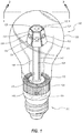
- an embodiment of the present invention is illustrated depicting an LED lighting device 100 having a plurality of panels 102 and LEDs 103 mounted to the panels 102 and advantageously arranged about a central axis for space lighting - i . e ., lighting in a non-unidirectional fashion similar to that provided using incandescent bulbs. Illumination from the lighting device 100 is provided by the plurality of LEDs 103.
- a glass or plastic bulb (or transparent housing) 106 encases the LEDs and the various components that incorporate the assembled lighting device 100 and is sized such that the bulb 106 appears like a traditional light bulb. If desired, the bulb can be frosted, colored or transparent, which further permits the lighting device 100 to appear as a traditional light source
- the panels 102 are mounted to a multi-faceted frame 124.
- a heat conduction pipe 105 extends substantially along the central axis referred to above and includes a proximal end 120 and a distal end 122.
- the heat conduction pipe refers to any structure or material capable of conducting heat from high to low temperature.
- the frame 124 is secured to the proximal end 120 of the heat conduction pipe 105.
- the frame 124 has an upper 126 and lower 128 surface with holes 132 extending through the surfaces for mounting the frame 124 to a rod-like 130 portion of the heat conduction pipe 105.
- the frame 124 can be secured to the heat conduction pipe 105 using a tight friction-fit or a heat conductive paste between the outer surface of the pipe 105 and the inner surface of the holes 132 or using suitable adhesives or fasteners.
- the frame 124 can be solid or hollow, depending on the heat load or weight requirements.
- the frame 124 is advantageously constructed from metal sheet stock - e.g., aluminum or any other heat conducting material - and constructed using fold lines positioned on the sheet stock to yield the desired three-dimensional multifaceted shape or design.
- the frame can be constructed using a slug of metal or any other heat conducting material, the slug being cast or machined or otherwise molded into the desired multifaceted shape or design.
- Embodiments employing the hollow design may include heat conducting means - e.g ., rods or fins - connecting the frame 124 to the heat conducting pipe 105 for enhanced transfer of heat from the frame to the pipe.
- the facets of the frame 124 can be vertical or angel positively or negatively, depending upon the desired light beam profile of the lighting device 100 and the emitting patterns of the component LEDs.
- the plurality of panels 102 and LEDs 103 are secured to one or more of the faces of the multi-faceted frame 124.
- pairs of screws 134 secure corresponding panels 102 to each face of the frame 124.
- the light emitting portion of each LED 103 extends through a hole in the panel 102 while the backside of the LED is attached to either the panel 102 or the face of the frame or both using a heat conductive paste 144.
- the LEDs 103 are wired in series by connecting corresponding positive and negative leads from each LED 103 using wires 104.
- the LEDs can also be connected using combinations of serial and parallel circuitry depending on the components used and the requirements of the electronic driver.
- a pair of power conducting wires 140, 142 supply power to the LEDs 103 from an electronic driver 145.
- the electronic driver 145 is used to covert AC input to DC output that is generally required to drive LED circuitry, electrically isolate various components of the device from one another and to control operation of the LEDs - e.g., control dimming.
- the electronic driver 145 is positioned inside a standard Edison base 111 of the lighting device 100 and connected to the Edison base which generally receives AC power through conducting leads 246, 247. However, if the LEDs on the frame 124 can be driven directly by AC power, then the electronic driver 145 is not required in the embodiment.
- the threaded base portion generally comprises the components and sizes associated with a standard Edison screw base - e.g ., size E27, and ranging from E5 to E40; while threaded base portions are generally preferred for connection with an external supply of power, other means of connection - e.g., pins or prongs - are considered within the scope of the invention.
- Surface mounted LEDs are generally preferred for the foregoing embodiment, and those skilled in the art will appreciate that while the above description refers to wiring the LEDs in series, the LEDs are also readily wired in parallel or using combinations of series and parallel circuitry.
- the distal end 122 of the heat conduction pipe 105 extends into a heat sink 108.
- the heat sink 108 is illustrated having fins 110 for dissipation of heat, although rods or other configurations of heat dissipations means may be used.
- the fins 110 extend from a heat conducting slug 112 that conducts heat away from the distal end of the heat conduction tube 105 and to the fins 110.
- a fan assembly 114 is positioned below the heat sink 108 and directs a flow of cooling air past the fins 110 of the heat sink 108.
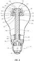
- the bulb 106 may be completely sealed, as illustrated in FIG. 2 .
- the flow of cooling air is directed through the fins 110 and about the outer surface of the bulb 106.
- the bulb 106 may include an opening adjacent the fins 110, in which case the flow of cooling air is directed past the fins 110 and into the interior of the bulb 106.
- a storage space 116 is incorporated into the lighting device 100, typically above the threaded base portion 111 and the below the heat sink 108.
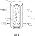
- a heat conduction pipe 150 for use with the present invention includes a sealed cylindrical tube 152, a wicking structure 154, a working fluid within the wicking structure 152 and a hollow space 156 interior to the wicking structure 154.
- Application of heat at a proximal end 170 of the heat conduction pipe 150 causes the working fluid at that point to evaporate to the gaseous state, picking up the latent heat of vaporization.
- the gas which then has a higher pressure, travels along the hollow space 156 toward the cooler distal end 172 where it condenses back to the liquid state, releasing the latent heat of vaporization to the distal end 172 of the heat conduction pipe 150.
- the condensed working fluid then travels back along the wicking structure 152 toward the proximal end 170 and repeats the process.
- the heat conducting pipe may include an interior section housing an interior solid material having a melting point below that of the material used to construct the heat pipe.
- the latent heat of melting of the interior material may be used to store a portion of the heat generated by the LEDs as the interior material changes phase from a solid to a liquid.
- the heat conduction pipe is constructed of aluminum or copper and houses an interior material comprising tin or lead, both of which exhibit melting points substantially below that of both copper and aluminum.
- Gallium may also be used as a suitable metal for the interior material.
- a still further alternative is to substitute a solid rod, constructed using materials having good heat conduction properties, e . g . aluminum or copper, for the more conventional heat conduction pipes described above.
- the heat conduction pipe is a cylindrical rod between about two (2) and about three (3) inches in length and between about one-quarter (1/4) and about three-quarters (3/4) inch in diameter and constructed of copper;
- the heat sink 108 including the heat slug 112
- the frame is a six-sided hexagon-shaped hollow frame constructed of aluminum sheet, having an average diameter between about one-half (1/2) and about one (1) inch, a length between about one-quarter (1/4) and about one (1) inch and a sheet thickness of between about one thirty-second (1/32) and about one quarter (1/4) inch.
- the shape of the bulb 106 approximates the shape of a standard 100W incandescent bulb having a standard E27 Edison screw base.
- An LED lighting device 200 includes a plurality of LED chips 203 that are mounted to a multi-faceted frame 224 and advantageously arranged about a central axis for space lighting. Illumination from the lighting device 200 is provided by the plurality of LED chips 203.
- This lighting configuration is similar to that discussed above regarding FIGS. 1 and 2 , with the exception that the lighting in the current embodiment is provided by LED chips mounted on the multi-faceted lead frame 224, rather than surface mounted LEDs.
- Various exemplar chips suitable for use with the present invention are disclosed in US Pat. No. 6,719,446 (Cao), the disclosures of which were previously incorporated by reference.
- the LED chips 203 are mounted directly to the multi-faceted frame 224. Suitable adhesives, such as epoxy, may be used to mount each chip to the frame 224.
- a glass or plastic bulb 206 encases the LED chips and frame 224 and, as detailed below, the various components that incorporate the assembled lighting device 200.
- an optional layer of phosphor 250 encases one or more of the LED chips 203.
- the layer of phosphor is advantageous in that it, for example, in one embodiment, produces a white light or the appearance of a white light - e.g., by using an ultraviolet LED chip to stimulate a white-emitting phosphor or by using a blue LED chip to stimulate a yellow-emitting phosphor, the yellow light stimulating the red and green receptors of the eye, with the resulting mix of red, green and blue providing the appearance of white light.
- white light or the appearance thereof is produced through use of a plurality of 450-470nm blue gallium nitride LED chips covered by a layer of yellowish phosphor of cerium doped yttrium aluminum garnet crystals.
- the LED chips are electrically connected within the lighting device 200, in one embodiment, by connecting a negative terminal of each chip to the frame 224 using a first wire 210 and by connecting a positive terminal of each chip to an electrically conducting cap 212 using a second wire 214.
- the electrically conducting cap 212 is positioned atop the frame 224 and electrically insulated therefrom by an insulation layer 216, which can be constructed using epoxy, AIO or any other material having electrically insulating properties.
- a pair of electrical conducting wires 240, 242 supply power to the LED chips 203 from a standard threaded base portion 211 of the bulb device 200.
- the pair of power supply wires 240,242 extend, respectively, from corresponding contacts at the base portion 211 to the electronic driver 245 inside.
- the electronic driver 245 is used to covert AC input to DC output that is generally required to drive LED circuitry, electrically isolate various components of the device from one another and control operation of the LEDs - e.g., control dimming.
- the electronic driver 245 is positioned inside a standard Edison base 211 of the lighting device 200 and connected to the Edison base which generally receives AC power through conducting leads 246, 247.
- the LEDs on the frame 224 can be driven directly by AC power, then the electronic driver 245 is not required in the embodiment. In this sense, the LED chips 203 are wired in parallel.
- an epoxy cap 208 is used to cover the frame 224, first and second wires 210, 214, LED chips 203 and phosphor layer 250, among other components of the lighting device.
- the epoxy cap 208 acts as an optical lens and also as a protection layer for the various identified components.
- a heat conduction pipe 205 extends substantially along a central axis of the lighting device 200 and includes a proximal end 220 and a distal end 222.
- the frame 224 is secured to the proximal end 220 of the heat conduction pipe 205 in a manner similar to that described above with the previous embodiments.
- the distal end 222 of the heat conduction pipe 205 extends into a heat stink 208 that is constructed and positioned similar to that described above with the previous embodiments.
- An LED lighting device 300 has a plurality of panels 302 and LEDs 303 mounted to the panels 302 and advantageously arranged about a central axis for space lighting. Illumination from the lighting device 300 is provided by the plurality of LEDs 303.
- a glass or plastic bulb 306 encases the LEDs and, as detailed below, the various components that incorporate the assembled lighting device 300.
- the panels 302, in one embodiment, are mounted to a multi-faceted frame 324, which can be constructed as described with respect to the embodiments referred to above.
- the shape of the frame 324 in this embodiment approximates a sphere, such that vectors pointing outwardly normal from each face sweep in both longitudinal and latitudinal directions with respect to the sphere approximated by the frame, thereby producing a higher degree of omni-directional special lighting - i.e., a closer approximation to light emanating outward in a spherical direction, with the greater the number of faces in the longitudinal and latitudinal directions, the better the approximation.
- a heat conduction pipe 305 extends substantially along a central axis of the lighting device 300 and includes a proximal end 320 and a distal end 322.
- the frame 324 is secured to the proximal end 320 of the heat conduction pipe 305 in a manner similar to that described above with the previous embodiments.
- the distal end 322 of the heat conduction pipe 305 extends into a heat silk 308 that is constructed and positioned similar to that described above with the previous embodiments.
- An LED lighting device 400 includes a first heat sink in the form of a disk-shaped frame 424 and a plurality of LEDs 403 mounted to the frame 424 and advantageously arranged about the frame for directional space lighting. Illumination from the lighting device 400 is provided by the plurality of LEDs 403.
- the LEDs 403 are wired in series using connecting wires 404.
- a pair of electrical conducting wires 440,442 supply power to the series-wired LEDs 403 from a standard threaded base portion 411 of the lighting device 400.
- An electronic driver inside the base 411 provides power to the LEDs.
- the frame 424 can be constructed as described with respect to the frame elements of the embodiments referred to above - i . e ., the frame can be solid or hollow.
- the frame 424 includes a first or upper surface 451 and a second or lower surface 452 and a plurality of heat dissipating fins 453 disposed between the two surfaces.
- a heat conduction pipe 405 extends substantially along a central axis of the lighting device 400 and includes a proximal end 420 and a distal end 422.
- the frame 424 is secured to the proximal end 420 of the heat conduction pipe 405 in a manner similar to that described above with the previous embodiments.
- the distal end 422 of the heat conduction pipe 405 extends into a heat sink 408 that is constructed and positioned similar to that described above with the previous embodiments.
- the LED devices or LED chips used to construct the lighting devices described above may emit single or multiple colors or white color.
- the bulbs or encapsulating cover can also be frosted or clear or coated with phosphor to convert the light from LED to different colors as required. While certain embodiments and details have been included herein and in the attached invention disclosure for purposes of illustrating the invention, it will be apparent to those skilled in the art that various changes in the methods and apparatuses disclosed herein may be made without departing from the scope of the invention, which is defined in the appended claims.
Landscapes
- Engineering & Computer Science (AREA)
- General Engineering & Computer Science (AREA)
- Physics & Mathematics (AREA)
- Microelectronics & Electronic Packaging (AREA)
- Optics & Photonics (AREA)
- Arrangement Of Elements, Cooling, Sealing, Or The Like Of Lighting Devices (AREA)
- Non-Portable Lighting Devices Or Systems Thereof (AREA)
Description
- The present invention relates to the field of LED lighting and, more particularly, to concentrated LED lighting devices that transfer heat quickly to a separate heat sink with or without active cooling to dissipate the heat away from the concentrated LED light source.
- Light emitting diodes (LEDs) are considered an efficient light source to replace incandescent, compact fluorescent lights (CFLs) and other more conventional light sources to save electrical energy. LEDs use significantly less than the energy required by incandescent lights to produce comparable amounts of light. The energy savings ranges from 40 to 80% depending on the design of light bulbs. In addition, LEDs contain no environmental harming elements, such as mercury that is commonly used in CFLs. Light bulbs using LEDs as the light source for replacing traditional incandescent bulbs, CFLs and other conventional sources are required to produce the same as or better quantities and qualities of light. The quantity of the light depends on light output, which can be increased with increasing LED efficiency, number or size, as well as electronic driver efficiency. The quality of the light is related to factors affecting the color rendering index and the light beam profile. Since most packaged LED devices do not emit light omni-directionally, a challenge exists when designing replacement bulbs using packaged LEDs that do emit light omni-directionally. On the other hand, LEDs emitting in one direction can be easily adopted for down lighting as is done with MR16 lights with heat management systems and an electronic driver. However, in order to radiate light spatially using LEDs - i.e., in a non-unidirectional or omni-directional fashion similar to that provided using incandescent bulbs - a special three-dimensional positioning arrangement for multiple LEDs is generally required. Various embodiments of spatial, radial or otherwise non-unidirectional lighting using LEDs have been described in the prior art, with examples being found in:
US Patent No. 6,634,770 (Cao);US Patent No. 6,634, 771 (Cao);U.S. Patent No. 6,465,961 (Cao);U.S. Patent No. 6,719,446 (Cao) issued April 13, 2004. Various further examples can be found in co-owned and pending US patent applications, having Serial Nos.11/397,323 11/444,166 11/938,131 DE 20 2006 017 356 U1 discloses a lamp where the developed heat of a light emitting device is removed by a cooling casing and a cooling module.US 2008/0253125 A1 discloses an LED lighting assembly including a heat exchange base, at least one LED array, at least one heat pipe and a heat dissipation module. The invention described below advances the prior art devices through inventive means of advantageously transferring heat energy away from the LED lighting device to a separate heat sink to dissipate the heat away from the LED light source. The invention thus helps to improve heat management and light beam profiles in LED-based lighting. - According to one aspect, there is provided a lighting device as claimed in claim 1. Embodiments of the invention provide a 3 dimensional LED arrangement and heat management method using a heat transfer pipe to enable the heat transferred quickly from a 3 dimensional cluster of LEDs to a heatsink with/without active cooling. The light emitted from the 3 dimensional cluster is not obstructed by any heat sink arrangement so that the light beam profile can be similar to traditional incandescent bulbs.
-
-
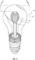
FIG. 1 provides a perspective view of one embodiment of an LED lighting device according to the present invention; -
FIG. 2 provides a cross sectional view of the LED lighting device illustrated inFIG. 1 ; -
FIG. 3 provides a cross sectional view of one embodiment of a heat pipe as used in the present invention; -
FIG. 4 provides a cross section view of a second embodiment of an LED lighting device according to the present invention; -
FIG. 5 provides a perspective view of a yet further embodiment of an LED lighting device according to the present invention; -
FIG. 6 provides a cross sectional view of the LED lighting device illustrated inFIG. 5 ; and -
FIG. 7 provides a cross sectional view of yet another embodiment of an LED lighting device according to the present invention. - Referring to
FIGS. 1 and2 , an embodiment of the present invention is illustrated depicting anLED lighting device 100 having a plurality ofpanels 102 andLEDs 103 mounted to thepanels 102 and advantageously arranged about a central axis for space lighting - i.e., lighting in a non-unidirectional fashion similar to that provided using incandescent bulbs. Illumination from thelighting device 100 is provided by the plurality ofLEDs 103. A glass or plastic bulb (or transparent housing) 106 encases the LEDs and the various components that incorporate the assembledlighting device 100 and is sized such that thebulb 106 appears like a traditional light bulb. If desired, the bulb can be frosted, colored or transparent, which further permits thelighting device 100 to appear as a traditional light source - The
panels 102, in one embodiment, are mounted to amulti-faceted frame 124. Aheat conduction pipe 105 extends substantially along the central axis referred to above and includes aproximal end 120 and adistal end 122. Generally speaking, the heat conduction pipe refers to any structure or material capable of conducting heat from high to low temperature. Theframe 124 is secured to theproximal end 120 of theheat conduction pipe 105. Theframe 124 has an upper 126 and lower 128 surface withholes 132 extending through the surfaces for mounting theframe 124 to a rod-like 130 portion of theheat conduction pipe 105. Theframe 124 can be secured to theheat conduction pipe 105 using a tight friction-fit or a heat conductive paste between the outer surface of thepipe 105 and the inner surface of theholes 132 or using suitable adhesives or fasteners. - Further, the
frame 124 can be solid or hollow, depending on the heat load or weight requirements. For a relatively lightweight lighting device, for example, theframe 124 is advantageously constructed from metal sheet stock - e.g., aluminum or any other heat conducting material - and constructed using fold lines positioned on the sheet stock to yield the desired three-dimensional multifaceted shape or design. On the other hand, for a relatively heavier lighting device, the frame can be constructed using a slug of metal or any other heat conducting material, the slug being cast or machined or otherwise molded into the desired multifaceted shape or design. Embodiments employing the hollow design may include heat conducting means - e.g., rods or fins - connecting theframe 124 to theheat conducting pipe 105 for enhanced transfer of heat from the frame to the pipe. The facets of theframe 124 can be vertical or angel positively or negatively, depending upon the desired light beam profile of thelighting device 100 and the emitting patterns of the component LEDs. - As further indicated in
FIGS. 1 and2 , the plurality ofpanels 102 andLEDs 103 are secured to one or more of the faces of themulti-faceted frame 124. In one embodiment, pairs ofscrews 134 securecorresponding panels 102 to each face of theframe 124. The light emitting portion of eachLED 103 extends through a hole in thepanel 102 while the backside of the LED is attached to either thepanel 102 or the face of the frame or both using a heatconductive paste 144. In one embodiment, theLEDs 103 are wired in series by connecting corresponding positive and negative leads from eachLED 103 usingwires 104. The LEDs can also be connected using combinations of serial and parallel circuitry depending on the components used and the requirements of the electronic driver. A pair of power conductingwires LEDs 103 from anelectronic driver 145. Theelectronic driver 145 is used to covert AC input to DC output that is generally required to drive LED circuitry, electrically isolate various components of the device from one another and to control operation of the LEDs - e.g., control dimming. Theelectronic driver 145 is positioned inside a standard Edisonbase 111 of thelighting device 100 and connected to the Edison base which generally receives AC power through conductingleads frame 124 can be driven directly by AC power, then theelectronic driver 145 is not required in the embodiment. The threaded base portion generally comprises the components and sizes associated with a standard Edison screw base - e.g., size E27, and ranging from E5 to E40; while threaded base portions are generally preferred for connection with an external supply of power, other means of connection - e.g., pins or prongs - are considered within the scope of the invention. Surface mounted LEDs are generally preferred for the foregoing embodiment, and those skilled in the art will appreciate that while the above description refers to wiring the LEDs in series, the LEDs are also readily wired in parallel or using combinations of series and parallel circuitry. - Still referring to
FIGS. 1 and2 , thedistal end 122 of theheat conduction pipe 105 extends into aheat sink 108. Theheat sink 108 is illustrated havingfins 110 for dissipation of heat, although rods or other configurations of heat dissipations means may be used. Thefins 110 extend from aheat conducting slug 112 that conducts heat away from the distal end of theheat conduction tube 105 and to thefins 110. In one embodiment, afan assembly 114 is positioned below theheat sink 108 and directs a flow of cooling air past thefins 110 of theheat sink 108. Thebulb 106 may be completely sealed, as illustrated inFIG. 2 . In such case, the flow of cooling air is directed through thefins 110 and about the outer surface of thebulb 106. Alternatively, thebulb 106 may include an opening adjacent thefins 110, in which case the flow of cooling air is directed past thefins 110 and into the interior of thebulb 106. Referring to embodiments where afan 114 is used, astorage space 116 is incorporated into thelighting device 100, typically above the threadedbase portion 111 and the below theheat sink 108. - Referring to
FIG. 3 , in one embodiment, aheat conduction pipe 150 for use with the present invention includes a sealedcylindrical tube 152, awicking structure 154, a working fluid within thewicking structure 152 and ahollow space 156 interior to thewicking structure 154. Application of heat at aproximal end 170 of theheat conduction pipe 150 causes the working fluid at that point to evaporate to the gaseous state, picking up the latent heat of vaporization. The gas, which then has a higher pressure, travels along thehollow space 156 toward the coolerdistal end 172 where it condenses back to the liquid state, releasing the latent heat of vaporization to thedistal end 172 of theheat conduction pipe 150. The condensed working fluid then travels back along thewicking structure 152 toward theproximal end 170 and repeats the process. - In an alternative embodiment the heat conducting pipe may include an interior section housing an interior solid material having a melting point below that of the material used to construct the heat pipe. In such case, the latent heat of melting of the interior material may be used to store a portion of the heat generated by the LEDs as the interior material changes phase from a solid to a liquid. In one embodiment, for example, the heat conduction pipe is constructed of aluminum or copper and houses an interior material comprising tin or lead, both of which exhibit melting points substantially below that of both copper and aluminum. Gallium may also be used as a suitable metal for the interior material. A still further alternative is to substitute a solid rod, constructed using materials having good heat conduction properties, e.g. aluminum or copper, for the more conventional heat conduction pipes described above.
- In one embodiment, the heat conduction pipe is a cylindrical rod between about two (2) and about three (3) inches in length and between about one-quarter (1/4) and about three-quarters (3/4) inch in diameter and constructed of copper; the
heat sink 108, including theheat slug 112, is between about one-half (1/2) and about one (1) inch in diameter and between about one-quarter (1/4) and about one (1) inch in thickness and constructed of aluminum; and the frame is a six-sided hexagon-shaped hollow frame constructed of aluminum sheet, having an average diameter between about one-half (1/2) and about one (1) inch, a length between about one-quarter (1/4) and about one (1) inch and a sheet thickness of between about one thirty-second (1/32) and about one quarter (1/4) inch. The shape of thebulb 106 approximates the shape of a standard 100W incandescent bulb having a standard E27 Edison screw base. - Referring now to
FIG. 4 , another embodiment of the present invention is illustrated. AnLED lighting device 200 includes a plurality ofLED chips 203 that are mounted to amulti-faceted frame 224 and advantageously arranged about a central axis for space lighting. Illumination from thelighting device 200 is provided by the plurality ofLED chips 203. This lighting configuration is similar to that discussed above regardingFIGS. 1 and2 , with the exception that the lighting in the current embodiment is provided by LED chips mounted on themulti-faceted lead frame 224, rather than surface mounted LEDs. Various exemplar chips suitable for use with the present invention are disclosed inUS Pat. No. 6,719,446 (Cao), the disclosures of which were previously incorporated by reference. As illustrated in the figure, theLED chips 203 are mounted directly to themulti-faceted frame 224. Suitable adhesives, such as epoxy, may be used to mount each chip to theframe 224. A glass orplastic bulb 206 encases the LED chips andframe 224 and, as detailed below, the various components that incorporate the assembledlighting device 200. - If desired, an optional layer of
phosphor 250 encases one or more of the LED chips 203. The layer of phosphor is advantageous in that it, for example, in one embodiment, produces a white light or the appearance of a white light - e.g., by using an ultraviolet LED chip to stimulate a white-emitting phosphor or by using a blue LED chip to stimulate a yellow-emitting phosphor, the yellow light stimulating the red and green receptors of the eye, with the resulting mix of red, green and blue providing the appearance of white light. In one embodiment, white light or the appearance thereof is produced through use of a plurality of 450-470nm blue gallium nitride LED chips covered by a layer of yellowish phosphor of cerium doped yttrium aluminum garnet crystals. - The LED chips are electrically connected within the
lighting device 200, in one embodiment, by connecting a negative terminal of each chip to theframe 224 using afirst wire 210 and by connecting a positive terminal of each chip to an electrically conductingcap 212 using asecond wire 214. Theelectrically conducting cap 212 is positioned atop theframe 224 and electrically insulated therefrom by aninsulation layer 216, which can be constructed using epoxy, AIO or any other material having electrically insulating properties. A pair ofelectrical conducting wires LED chips 203 from a standard threadedbase portion 211 of thebulb device 200. The pair of power supply wires 240,242 extend, respectively, from corresponding contacts at thebase portion 211 to theelectronic driver 245 inside. Similar to that described above, theelectronic driver 245 is used to covert AC input to DC output that is generally required to drive LED circuitry, electrically isolate various components of the device from one another and control operation of the LEDs - e.g., control dimming. Theelectronic driver 245 is positioned inside astandard Edison base 211 of thelighting device 200 and connected to the Edison base which generally receives AC power through conducting leads 246, 247. However, if the LEDs on theframe 224 can be driven directly by AC power, then theelectronic driver 245 is not required in the embodiment. In this sense, theLED chips 203 are wired in parallel. As discussed in reference to the previous embodiment, however, series-wired counterparts to that disclosed in this embodiment are readily apparent to those skilled in the art and are considered within the scope of the present invention. If desired, anepoxy cap 208 is used to cover theframe 224, first andsecond wires LED chips 203 andphosphor layer 250, among other components of the lighting device. Theepoxy cap 208 acts as an optical lens and also as a protection layer for the various identified components. - Still referring to
FIG. 4 , aheat conduction pipe 205 extends substantially along a central axis of thelighting device 200 and includes a proximal end 220 and adistal end 222. Theframe 224 is secured to the proximal end 220 of theheat conduction pipe 205 in a manner similar to that described above with the previous embodiments. Likewise, thedistal end 222 of theheat conduction pipe 205 extends into aheat stink 208 that is constructed and positioned similar to that described above with the previous embodiments. The various embodiments of the heat conducting pipe and heat sink discussed above, including the means of cooling the same, apply equally to the embodiments just described with reference toFIGS. 1 and2 . - Referring now to
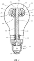
FIGS. 5 and6 , a still further embodiment of the present invention is disclosed. AnLED lighting device 300 has a plurality ofpanels 302 andLEDs 303 mounted to thepanels 302 and advantageously arranged about a central axis for space lighting. Illumination from thelighting device 300 is provided by the plurality ofLEDs 303. A glass orplastic bulb 306 encases the LEDs and, as detailed below, the various components that incorporate the assembledlighting device 300. Thepanels 302, in one embodiment, are mounted to amulti-faceted frame 324, which can be constructed as described with respect to the embodiments referred to above. More particularly, the shape of theframe 324 in this embodiment approximates a sphere, such that vectors pointing outwardly normal from each face sweep in both longitudinal and latitudinal directions with respect to the sphere approximated by the frame, thereby producing a higher degree of omni-directional special lighting - i.e., a closer approximation to light emanating outward in a spherical direction, with the greater the number of faces in the longitudinal and latitudinal directions, the better the approximation. - A
heat conduction pipe 305 extends substantially along a central axis of thelighting device 300 and includes aproximal end 320 and adistal end 322. Theframe 324 is secured to theproximal end 320 of theheat conduction pipe 305 in a manner similar to that described above with the previous embodiments. Likewise, thedistal end 322 of theheat conduction pipe 305 extends into aheat silk 308 that is constructed and positioned similar to that described above with the previous embodiments. The various embodiments of the heat conducting pipe and heat sink discussed above, including the means of cooling the same, apply equally to the embodiments described above. Further, it is noted that the various embodiments concerning the use of surface mounted LEDs and LED chips, including the manner of wiring in series or parallel, the optional use of phosphors or epoxy coverings and the optional use of a cooling fan, may be used with or incorporated into the embodiments depicted inFIGS. 5 and6 . - Referring now to
FIG. 7 , a still further embodiment of the present invention is illustrated and disclosed. AnLED lighting device 400 includes a first heat sink in the form of a disk-shapedframe 424 and a plurality ofLEDs 403 mounted to theframe 424 and advantageously arranged about the frame for directional space lighting. Illumination from thelighting device 400 is provided by the plurality ofLEDs 403. In one embodiment, theLEDs 403 are wired in series using connectingwires 404. A pair of electrical conducting wires 440,442 supply power to the series-wiredLEDs 403 from a standard threadedbase portion 411 of thelighting device 400. An electronic driver inside thebase 411 provides power to the LEDs. Theframe 424 can be constructed as described with respect to the frame elements of the embodiments referred to above - i.e., the frame can be solid or hollow. In an alternative embodiment, theframe 424 includes a first orupper surface 451 and a second orlower surface 452 and a plurality ofheat dissipating fins 453 disposed between the two surfaces. - A
heat conduction pipe 405 extends substantially along a central axis of thelighting device 400 and includes aproximal end 420 and adistal end 422. Theframe 424 is secured to theproximal end 420 of theheat conduction pipe 405 in a manner similar to that described above with the previous embodiments. Likewise, thedistal end 422 of theheat conduction pipe 405 extends into aheat sink 408 that is constructed and positioned similar to that described above with the previous embodiments. The various embodiments of the heat conducting pipe and heat sink discussed above, including the means of cooling the same, apply equally to the embodiments described above. Further, it is noted that the various embodiments concerning the use of surface mounted LEDs and LED chips, including the manner of wiring in series or parallel, the optional use of phosphors or epoxy coverings and the optional use of a cooling fan, may all be used with or incorporated into the embodiments depicted inFIG. 7 . - The LED devices or LED chips used to construct the lighting devices described above may emit single or multiple colors or white color. The bulbs or encapsulating cover can also be frosted or clear or coated with phosphor to convert the light from LED to different colors as required. While certain embodiments and details have been included herein and in the attached invention disclosure for purposes of illustrating the invention, it will be apparent to those skilled in the art that various changes in the methods and apparatuses disclosed herein may be made without departing from the scope of the invention, which is defined in the appended claims.
Claims (8)
- A lighting device (100 - 400), comprising:a frame (124 - 424);a plurality of LEDs (103 - 403) mounted on said frame;a heat sink (108 - 408) spaced from said frame;a heat conducting pipe (105 - 405) having a proximal end (120 - 420) and a distal end (122 - 422), said proximal end connected to said frame and said distal end connected to said heat sink;characterised by an electronic driver (145 - 345) positioned within a base portion with means for connection to an external source of power, said electronic driver being configured to connect to said external source of power, said heat sink being proximate both said electronic driver and said base portion; andfirst and second electric conducting wires (142 - 442; 140 - 440) connecting said electronic driver to said plurality of LEDs.
- The lighting device of claim 1, further comprising a transparent housing (106 - 306).
- The lighting device of claim 1, wherein the frame has six faces and a hexagonal cross section, and said plurality of LEDs are positioned on respective faces.
- The lighting device of claim 1, wherein the frame is multifaceted in both a longitudinal and latitudinal direction, and said plurality of LEDs are positioned on respective faces of said multifaceted frame.
- The lighting device of claim 1, wherein the heat conduction tube comprises an outer tube (152), a wicking material (154) and a working fluid.
- The lighting device of claim 1, wherein the heat conducting tube is constructed of a first material and includes an inner material having a melting temperature lower that the melting temperature of the first material.
- The heat device of claim 1, wherein the frame is constructed of a solid non-hollow piece of metal,
- The heat device of claim 1, wherein the frame is hollow and constructed of metal.
Priority Applications (1)
| Application Number | Priority Date | Filing Date | Title |
|---|---|---|---|
| EP17186663.5A EP3273161A1 (en) | 2009-02-17 | 2010-02-17 | Led light bulbs for space lighting |
Applications Claiming Priority (2)
| Application Number | Priority Date | Filing Date | Title |
|---|---|---|---|
| US20775109P | 2009-02-17 | 2009-02-17 | |
| PCT/US2010/024489 WO2010096498A1 (en) | 2009-02-17 | 2010-02-17 | Led light bulbs for space lighting |
Related Child Applications (1)
| Application Number | Title | Priority Date | Filing Date |
|---|---|---|---|
| EP17186663.5A Division EP3273161A1 (en) | 2009-02-17 | 2010-02-17 | Led light bulbs for space lighting |
Publications (3)
| Publication Number | Publication Date |
|---|---|
| EP2399070A1 EP2399070A1 (en) | 2011-12-28 |
| EP2399070A4 EP2399070A4 (en) | 2014-05-07 |
| EP2399070B1 true EP2399070B1 (en) | 2017-08-23 |
Family
ID=42559270
Family Applications (2)
| Application Number | Title | Priority Date | Filing Date |
|---|---|---|---|
| EP17186663.5A Pending EP3273161A1 (en) | 2009-02-17 | 2010-02-17 | Led light bulbs for space lighting |
| EP10744264.2A Active EP2399070B1 (en) | 2009-02-17 | 2010-02-17 | Led light bulbs for space lighting |
Family Applications Before (1)
| Application Number | Title | Priority Date | Filing Date |
|---|---|---|---|
| EP17186663.5A Pending EP3273161A1 (en) | 2009-02-17 | 2010-02-17 | Led light bulbs for space lighting |
Country Status (6)
| Country | Link |
|---|---|
| US (1) | US8653723B2 (en) |
| EP (2) | EP3273161A1 (en) |
| JP (1) | JP2012518254A (en) |
| KR (1) | KR20110117090A (en) |
| CN (1) | CN102301181A (en) |
| WO (1) | WO2010096498A1 (en) |
Families Citing this family (201)
| Publication number | Priority date | Publication date | Assignee | Title |
|---|---|---|---|---|
| US6200134B1 (en) | 1998-01-20 | 2001-03-13 | Kerr Corporation | Apparatus and method for curing materials with radiation |
| US7728345B2 (en) | 2001-08-24 | 2010-06-01 | Cao Group, Inc. | Semiconductor light source for illuminating a physical space including a 3-dimensional lead frame |
| US7182597B2 (en) | 2002-08-08 | 2007-02-27 | Kerr Corporation | Curing light instrument |
| US10340424B2 (en) | 2002-08-30 | 2019-07-02 | GE Lighting Solutions, LLC | Light emitting diode component |
| US8113830B2 (en) | 2005-05-27 | 2012-02-14 | Kerr Corporation | Curing light instrument |
| US9412926B2 (en) | 2005-06-10 | 2016-08-09 | Cree, Inc. | High power solid-state lamp |
| US9066777B2 (en) | 2009-04-02 | 2015-06-30 | Kerr Corporation | Curing light device |
| US9072572B2 (en) | 2009-04-02 | 2015-07-07 | Kerr Corporation | Dental light device |
| US8791499B1 (en) | 2009-05-27 | 2014-07-29 | Soraa, Inc. | GaN containing optical devices and method with ESD stability |
| US8922106B2 (en) * | 2009-06-02 | 2014-12-30 | Bridgelux, Inc. | Light source with optics to produce a spherical emission pattern |
| US20100301728A1 (en) * | 2009-06-02 | 2010-12-02 | Bridgelux, Inc. | Light source having a refractive element |
| US8186852B2 (en) * | 2009-06-24 | 2012-05-29 | Elumigen Llc | Opto-thermal solution for multi-utility solid state lighting device using conic section geometries |
| AU2010292992A1 (en) * | 2009-09-10 | 2012-05-03 | Hamish Mclennan | Improved light emitting diode (LED) assembly and method of manufacturing the same |
| US8678618B2 (en) * | 2009-09-25 | 2014-03-25 | Toshiba Lighting & Technology Corporation | Self-ballasted lamp having a light-transmissive member in contact with light emitting elements and lighting equipment incorporating the same |
| US8593040B2 (en) | 2009-10-02 | 2013-11-26 | Ge Lighting Solutions Llc | LED lamp with surface area enhancing fins |
| US9243758B2 (en) | 2009-10-20 | 2016-01-26 | Cree, Inc. | Compact heat sinks and solid state lamp incorporating same |
| US9217542B2 (en) | 2009-10-20 | 2015-12-22 | Cree, Inc. | Heat sinks and lamp incorporating same |
| US8622589B2 (en) * | 2010-02-08 | 2014-01-07 | Neobulb Technologies, Inc. | LED lighting device |
| US9625105B2 (en) | 2010-03-03 | 2017-04-18 | Cree, Inc. | LED lamp with active cooling element |
| US9062830B2 (en) * | 2010-03-03 | 2015-06-23 | Cree, Inc. | High efficiency solid state lamp and bulb |
| US20110227102A1 (en) * | 2010-03-03 | 2011-09-22 | Cree, Inc. | High efficacy led lamp with remote phosphor and diffuser configuration |
| US9057511B2 (en) | 2010-03-03 | 2015-06-16 | Cree, Inc. | High efficiency solid state lamp and bulb |
| US9052067B2 (en) | 2010-12-22 | 2015-06-09 | Cree, Inc. | LED lamp with high color rendering index |
| US8931933B2 (en) | 2010-03-03 | 2015-01-13 | Cree, Inc. | LED lamp with active cooling element |
| US9316361B2 (en) | 2010-03-03 | 2016-04-19 | Cree, Inc. | LED lamp with remote phosphor and diffuser configuration |
| US9310030B2 (en) | 2010-03-03 | 2016-04-12 | Cree, Inc. | Non-uniform diffuser to scatter light into uniform emission pattern |
| US9024517B2 (en) * | 2010-03-03 | 2015-05-05 | Cree, Inc. | LED lamp with remote phosphor and diffuser configuration utilizing red emitters |
| US9275979B2 (en) | 2010-03-03 | 2016-03-01 | Cree, Inc. | Enhanced color rendering index emitter through phosphor separation |
| US8882284B2 (en) | 2010-03-03 | 2014-11-11 | Cree, Inc. | LED lamp or bulb with remote phosphor and diffuser configuration with enhanced scattering properties |
| US8562161B2 (en) | 2010-03-03 | 2013-10-22 | Cree, Inc. | LED based pedestal-type lighting structure |
| US8632196B2 (en) * | 2010-03-03 | 2014-01-21 | Cree, Inc. | LED lamp incorporating remote phosphor and diffuser with heat dissipation features |
| US10359151B2 (en) * | 2010-03-03 | 2019-07-23 | Ideal Industries Lighting Llc | Solid state lamp with thermal spreading elements and light directing optics |
| US9500325B2 (en) | 2010-03-03 | 2016-11-22 | Cree, Inc. | LED lamp incorporating remote phosphor with heat dissipation features |
| US9157602B2 (en) | 2010-05-10 | 2015-10-13 | Cree, Inc. | Optical element for a light source and lighting system using same |
| KR20130079426A (en) * | 2010-05-11 | 2013-07-10 | 괴켄 그룹 코포레이션 | High intensity led replacement of incandescent lamps |
| US20110278633A1 (en) * | 2010-05-11 | 2011-11-17 | Scott Allen Clifford | LED Light Bulb With Integrated Heat Sink |
| JP4717148B1 (en) * | 2010-05-28 | 2011-07-06 | 株式会社スズデン | Lighting apparatus and method of manufacturing the lighting apparatus |
| US8227961B2 (en) | 2010-06-04 | 2012-07-24 | Cree, Inc. | Lighting device with reverse tapered heatsink |
| US8596821B2 (en) | 2010-06-08 | 2013-12-03 | Cree, Inc. | LED light bulbs |
| CN201696936U (en) * | 2010-06-13 | 2011-01-05 | 沈锦祥 | LED tower-shaped luminescent module |
| US10451251B2 (en) | 2010-08-02 | 2019-10-22 | Ideal Industries Lighting, LLC | Solid state lamp with light directing optics and diffuser |
| SG188483A1 (en) * | 2010-09-08 | 2013-04-30 | Zhejiang Ledison Optoelectronics Co Ltd | Led light bulb and led light-emitting strip being capable of emitting 4pi light |
| CN102401359A (en) * | 2010-09-15 | 2012-04-04 | 奇鋐科技股份有限公司 | Light emitting diode (LED) bulb radiating structure |
| US8272762B2 (en) * | 2010-09-28 | 2012-09-25 | Lighting Science Group Corporation | LED luminaire |
| US9279543B2 (en) | 2010-10-08 | 2016-03-08 | Cree, Inc. | LED package mount |
| US8803452B2 (en) | 2010-10-08 | 2014-08-12 | Soraa, Inc. | High intensity light source |
| CN102454966A (en) * | 2010-10-22 | 2012-05-16 | 富准精密工业(深圳)有限公司 | Heat radiation device and LED lamp applying same |
| TWM412319U (en) * | 2010-11-01 | 2011-09-21 | Parlux Optoelectronics Corp | LED illumination device |
| CN103052839A (en) | 2010-11-04 | 2013-04-17 | 松下电器产业株式会社 | Bulb-type lamp and illuminating device |
| JP5511977B2 (en) * | 2010-11-04 | 2014-06-04 | パナソニック株式会社 | Light bulb shaped lamp and lighting device |
| TWI422776B (en) * | 2010-12-15 | 2014-01-11 | Cal Comp Electronics & Comm Co | Lighting apparatus |
| JP5691542B2 (en) | 2011-01-18 | 2015-04-01 | トヨタ紡織株式会社 | Vehicle seat slide device |
| US20130294082A1 (en) * | 2011-01-18 | 2013-11-07 | Panasonic Corporation | Light bulb shaped lamp and lighting apparatus |
| US9234655B2 (en) | 2011-02-07 | 2016-01-12 | Cree, Inc. | Lamp with remote LED light source and heat dissipating elements |
| US9068701B2 (en) * | 2012-01-26 | 2015-06-30 | Cree, Inc. | Lamp structure with remote LED light source |
| US8829774B1 (en) | 2011-02-11 | 2014-09-09 | Soraa, Inc. | Illumination source with direct die placement |
| US10036544B1 (en) | 2011-02-11 | 2018-07-31 | Soraa, Inc. | Illumination source with reduced weight |
| US11251164B2 (en) | 2011-02-16 | 2022-02-15 | Creeled, Inc. | Multi-layer conversion material for down conversion in solid state lighting |
| US20120224371A1 (en) * | 2011-03-02 | 2012-09-06 | Kinpo Electronics, Inc. | Lighting apparatus |
| CA2830284C (en) * | 2011-03-17 | 2016-04-12 | Beijing Ugetlight Co., Ltd. | Liquid-cooled led illuminating lamp |
| US8461752B2 (en) * | 2011-03-18 | 2013-06-11 | Abl Ip Holding Llc | White light lamp using semiconductor light emitter(s) and remotely deployed phosphor(s) |
| US8272766B2 (en) * | 2011-03-18 | 2012-09-25 | Abl Ip Holding Llc | Semiconductor lamp with thermal handling system |
| US8803412B2 (en) | 2011-03-18 | 2014-08-12 | Abl Ip Holding Llc | Semiconductor lamp |
| DE102011007221B4 (en) * | 2011-04-12 | 2022-05-19 | Ledvance Gmbh | lighting device |
| US10030863B2 (en) * | 2011-04-19 | 2018-07-24 | Cree, Inc. | Heat sink structures, lighting elements and lamps incorporating same, and methods of making same |
| US9470882B2 (en) | 2011-04-25 | 2016-10-18 | Cree, Inc. | Optical arrangement for a solid-state lamp |
| US9797589B2 (en) | 2011-05-09 | 2017-10-24 | Cree, Inc. | High efficiency LED lamp |
| US10094548B2 (en) | 2011-05-09 | 2018-10-09 | Cree, Inc. | High efficiency LED lamp |
| US9360202B2 (en) * | 2011-05-13 | 2016-06-07 | Lighting Science Group Corporation | System for actively cooling an LED filament and associated methods |
| US8414160B2 (en) * | 2011-06-13 | 2013-04-09 | Tsmc Solid State Lighting Ltd. | LED lamp and method of making the same |
| US8981636B2 (en) * | 2011-07-22 | 2015-03-17 | Panasonic Intellectual Property Management Co., Ltd. | Lamp having improved insulation of the circuit unit |
| US8746915B2 (en) * | 2011-07-29 | 2014-06-10 | Cree, Inc. | Light emitting die (LED) lamps, heat sinks and related methods |
| CN202140877U (en) * | 2011-08-02 | 2012-02-08 | 惠州市东扬科技有限公司 | SMD LED lamp bulb |
| USD736724S1 (en) | 2011-08-15 | 2015-08-18 | Soraa, Inc. | LED lamp with accessory |
| USD736723S1 (en) | 2011-08-15 | 2015-08-18 | Soraa, Inc. | LED lamp |
| KR101326518B1 (en) | 2011-09-02 | 2013-11-07 | 엘지이노텍 주식회사 | Lighting device |
| US9109760B2 (en) | 2011-09-02 | 2015-08-18 | Soraa, Inc. | Accessories for LED lamps |
| US9488324B2 (en) | 2011-09-02 | 2016-11-08 | Soraa, Inc. | Accessories for LED lamp systems |
| WO2013042662A1 (en) | 2011-09-20 | 2013-03-28 | シチズンホールディングス株式会社 | Led module and led lamp employing same |
| US8884517B1 (en) | 2011-10-17 | 2014-11-11 | Soraa, Inc. | Illumination sources with thermally-isolated electronics |
| CN104254904A (en) * | 2011-10-31 | 2014-12-31 | 登森·西尔 | Led light source |
| KR101318432B1 (en) * | 2011-11-14 | 2013-10-16 | 아이스파이프 주식회사 | Led lighting apparatus |
| JP2013105711A (en) * | 2011-11-16 | 2013-05-30 | Toshiba Lighting & Technology Corp | Luminaire |
| KR20130058350A (en) * | 2011-11-25 | 2013-06-04 | 삼성전자주식회사 | Light emitting diode for automobile lamp |
| US9482421B2 (en) | 2011-12-30 | 2016-11-01 | Cree, Inc. | Lamp with LED array and thermal coupling medium |
| KR102017538B1 (en) | 2012-01-31 | 2019-10-21 | 엘지이노텍 주식회사 | Lighting device |
| TWI491830B (en) * | 2012-02-14 | 2015-07-11 | Av Tech Corp | Illuminating device with variable light beam and assemble method thereof |
| JP5934947B2 (en) * | 2012-02-16 | 2016-06-15 | パナソニックIpマネジメント株式会社 | Lamp and light emitting device |
| US9194556B1 (en) * | 2012-02-22 | 2015-11-24 | Theodore G. Nelson | Method of producing LED lighting apparatus and apparatus produced thereby |
| US9228728B2 (en) * | 2012-02-23 | 2016-01-05 | Koninklijke Philips N.V. | Luminaire module |
| US9488359B2 (en) | 2012-03-26 | 2016-11-08 | Cree, Inc. | Passive phase change radiators for LED lamps and fixtures |
| US9022601B2 (en) | 2012-04-09 | 2015-05-05 | Cree, Inc. | Optical element including texturing to control beam width and color mixing |
| US9310028B2 (en) | 2012-04-13 | 2016-04-12 | Cree, Inc. | LED lamp with LEDs having a longitudinally directed emission profile |
| US9234638B2 (en) | 2012-04-13 | 2016-01-12 | Cree, Inc. | LED lamp with thermally conductive enclosure |
| US8757839B2 (en) | 2012-04-13 | 2014-06-24 | Cree, Inc. | Gas cooled LED lamp |
| US9322543B2 (en) | 2012-04-13 | 2016-04-26 | Cree, Inc. | Gas cooled LED lamp with heat conductive submount |
| US9651240B2 (en) * | 2013-11-14 | 2017-05-16 | Cree, Inc. | LED lamp |
| US9395051B2 (en) | 2012-04-13 | 2016-07-19 | Cree, Inc. | Gas cooled LED lamp |
| US9410687B2 (en) | 2012-04-13 | 2016-08-09 | Cree, Inc. | LED lamp with filament style LED assembly |
| US9395074B2 (en) | 2012-04-13 | 2016-07-19 | Cree, Inc. | LED lamp with LED assembly on a heat sink tower |
| US9951909B2 (en) | 2012-04-13 | 2018-04-24 | Cree, Inc. | LED lamp |
| US9310065B2 (en) | 2012-04-13 | 2016-04-12 | Cree, Inc. | Gas cooled LED lamp |
| US8985794B1 (en) | 2012-04-17 | 2015-03-24 | Soraa, Inc. | Providing remote blue phosphors in an LED lamp |
| US9500355B2 (en) | 2012-05-04 | 2016-11-22 | GE Lighting Solutions, LLC | Lamp with light emitting elements surrounding active cooling device |
| US8680755B2 (en) | 2012-05-07 | 2014-03-25 | Lg Innotek Co., Ltd. | Lighting device having reflectors for indirect light emission |
| US9360190B1 (en) | 2012-05-14 | 2016-06-07 | Soraa, Inc. | Compact lens for high intensity light source |
| US10436422B1 (en) | 2012-05-14 | 2019-10-08 | Soraa, Inc. | Multi-function active accessories for LED lamps |
| US9995439B1 (en) | 2012-05-14 | 2018-06-12 | Soraa, Inc. | Glare reduced compact lens for high intensity light source |
| US9310052B1 (en) | 2012-09-28 | 2016-04-12 | Soraa, Inc. | Compact lens for high intensity light source |
| RU2631661C2 (en) * | 2012-05-29 | 2017-09-26 | Филипс Лайтинг Холдинг Б.В. | Lighting device, having heater of source of light, placed separately from driver |
| WO2013182937A1 (en) * | 2012-06-04 | 2013-12-12 | Koninklijke Philips N.V. | Lamp comprising a flexible printed circuit board |
| RU2637306C2 (en) | 2012-06-04 | 2017-12-04 | Конинклейке Филипс Н.В. | Assembly of led lamp, especially for automobile lamps |
| CN102748622A (en) * | 2012-06-25 | 2012-10-24 | 歌尔声学股份有限公司 | LED (Light-Emitting Diode) bulb lamp |
| KR20150036646A (en) * | 2012-07-25 | 2015-04-07 | 선전 이케 일렉트로옵티컬 테크놀로지 씨오., 엘티디. | Led automobile headlamp |
| US9097393B2 (en) | 2012-08-31 | 2015-08-04 | Cree, Inc. | LED based lamp assembly |
| US9097396B2 (en) | 2012-09-04 | 2015-08-04 | Cree, Inc. | LED based lighting system |
| US20140098528A1 (en) * | 2012-10-04 | 2014-04-10 | Tadd, LLC | Led retrofit lamp |
| US20140098568A1 (en) * | 2012-10-04 | 2014-04-10 | Tadd, LLC | Led retrofit lamp |
| US9134006B2 (en) | 2012-10-22 | 2015-09-15 | Cree, Inc. | Beam shaping lens and LED lighting system using same |
| KR20140056826A (en) | 2012-11-01 | 2014-05-12 | 삼성전자주식회사 | Light emitting device |
| CN102927476B (en) * | 2012-11-08 | 2014-08-20 | 浙江阳光照明电器集团股份有限公司 | Light emitting diode (LED) spherical lamp transmitting heat through liquid |
| US9215764B1 (en) | 2012-11-09 | 2015-12-15 | Soraa, Inc. | High-temperature ultra-low ripple multi-stage LED driver and LED control circuits |
| CN103851372B (en) * | 2012-12-04 | 2016-06-29 | 展晶科技(深圳)有限公司 | Light emitting diode bulb |
| US9062863B2 (en) | 2012-12-10 | 2015-06-23 | Avago Technologies General Ip (Singapore) Pte. Ltd. | System, device, and method for adjusting color output through active cooling mechanism |
| CN103047569B (en) * | 2012-12-20 | 2015-10-28 | 华南理工大学 | A kind of LED lamp bulb structure |
| CN102980163B (en) * | 2012-12-20 | 2015-07-22 | 纳晶科技股份有限公司 | Heat conduction connector for lamp and lamp including same |
| US9570661B2 (en) | 2013-01-10 | 2017-02-14 | Cree, Inc. | Protective coating for LED lamp |
| JP2014146510A (en) * | 2013-01-29 | 2014-08-14 | Panasonic Corp | Light source for lighting and lighting device |
| US9303857B2 (en) | 2013-02-04 | 2016-04-05 | Cree, Inc. | LED lamp with omnidirectional light distribution |
| US9267661B1 (en) | 2013-03-01 | 2016-02-23 | Soraa, Inc. | Apportioning optical projection paths in an LED lamp |
| US9435525B1 (en) | 2013-03-08 | 2016-09-06 | Soraa, Inc. | Multi-part heat exchanger for LED lamps |
| US9664369B2 (en) | 2013-03-13 | 2017-05-30 | Cree, Inc. | LED lamp |
| US9115870B2 (en) | 2013-03-14 | 2015-08-25 | Cree, Inc. | LED lamp and hybrid reflector |
| US9052093B2 (en) | 2013-03-14 | 2015-06-09 | Cree, Inc. | LED lamp and heat sink |
| US9243777B2 (en) | 2013-03-15 | 2016-01-26 | Cree, Inc. | Rare earth optical elements for LED lamp |
| US9657922B2 (en) | 2013-03-15 | 2017-05-23 | Cree, Inc. | Electrically insulative coatings for LED lamp and elements |
| US9435492B2 (en) | 2013-03-15 | 2016-09-06 | Cree, Inc. | LED luminaire with improved thermal management and novel LED interconnecting architecture |
| US8899794B2 (en) | 2013-03-15 | 2014-12-02 | Bby Solutions, Inc. | LED bulb optical system with uniform light distribution |
| US9285082B2 (en) | 2013-03-28 | 2016-03-15 | Cree, Inc. | LED lamp with LED board heat sink |
| US8894252B2 (en) * | 2013-04-19 | 2014-11-25 | Technical Consumer Products, Inc. | Filament LED lamp |
| US10094523B2 (en) | 2013-04-19 | 2018-10-09 | Cree, Inc. | LED assembly |
| US9310031B2 (en) * | 2013-06-06 | 2016-04-12 | Interlight Optotech Corporation | Light emitting diode bulb |
| TWI626395B (en) * | 2013-06-11 | 2018-06-11 | 晶元光電股份有限公司 | Light emitting device |
| PL224281B1 (en) | 2013-08-05 | 2016-12-30 | Skrobotowicz Piotr Auto Power Electronic | Light bulb with LEDs |
| CN103471063A (en) * | 2013-09-23 | 2013-12-25 | 立达信绿色照明股份有限公司 | High heat-dissipating bulb |
| JP5617982B2 (en) * | 2013-09-25 | 2014-11-05 | 東芝ライテック株式会社 | Lamp with lamp and lighting equipment |
| US9541241B2 (en) | 2013-10-03 | 2017-01-10 | Cree, Inc. | LED lamp |
| CN203641941U (en) * | 2013-10-31 | 2014-06-11 | 陈清辉 | LED bulb |
| CN103574368B (en) * | 2013-11-12 | 2015-11-04 | 无锡天地合同能源管理有限公司 | LEDbulb lamp |
| CN104676289A (en) * | 2013-11-26 | 2015-06-03 | 苏州承源光电科技有限公司 | LED lighting lamp |
| TWI553266B (en) * | 2014-01-13 | 2016-10-11 | 國立臺灣科技大學 | Liquid cooled led light emitting device |
| US10030819B2 (en) | 2014-01-30 | 2018-07-24 | Cree, Inc. | LED lamp and heat sink |
| US9464802B2 (en) * | 2014-02-19 | 2016-10-11 | Ozyegin Universitesi | Flow controlled effective LED based lighting system |
| US9360188B2 (en) | 2014-02-20 | 2016-06-07 | Cree, Inc. | Remote phosphor element filled with transparent material and method for forming multisection optical elements |
| US9518704B2 (en) | 2014-02-25 | 2016-12-13 | Cree, Inc. | LED lamp with an interior electrical connection |
| US9759387B2 (en) | 2014-03-04 | 2017-09-12 | Cree, Inc. | Dual optical interface LED lamp |
| US9462651B2 (en) | 2014-03-24 | 2016-10-04 | Cree, Inc. | Three-way solid-state light bulb |
| US9562677B2 (en) | 2014-04-09 | 2017-02-07 | Cree, Inc. | LED lamp having at least two sectors |
| US9435528B2 (en) | 2014-04-16 | 2016-09-06 | Cree, Inc. | LED lamp with LED assembly retention member |
| US9488322B2 (en) | 2014-04-23 | 2016-11-08 | Cree, Inc. | LED lamp with LED board heat sink |
| US9618162B2 (en) | 2014-04-25 | 2017-04-11 | Cree, Inc. | LED lamp |
| US9951910B2 (en) | 2014-05-19 | 2018-04-24 | Cree, Inc. | LED lamp with base having a biased electrical interconnect |
| CN103982822A (en) * | 2014-05-28 | 2014-08-13 | 昆山生态屋建筑技术有限公司 | Reflector lamp with fan arranged on heat conduction pillar |
| US9618163B2 (en) | 2014-06-17 | 2017-04-11 | Cree, Inc. | LED lamp with electronics board to submount connection |
| TW201600790A (en) * | 2014-06-27 | 2016-01-01 | Formosa Optronics Co Ltd | Omnidirectional lamp |
| US9488767B2 (en) | 2014-08-05 | 2016-11-08 | Cree, Inc. | LED based lighting system |
| CN204141334U (en) * | 2014-10-10 | 2015-02-04 | 佛山燊业光电有限公司 | A kind of comprehensive LEDbulb lamp without blackening |
| CN104406070B (en) * | 2014-11-19 | 2017-01-11 | 广州荣基能亮节能科技有限公司 | Three-dimensional luminous LED (Light Emitting Diode) bulb lamp and preparation method thereof |
| KR101702186B1 (en) * | 2014-11-28 | 2017-02-13 | 백두산 | Lighting device |
| US9401468B2 (en) | 2014-12-24 | 2016-07-26 | GE Lighting Solutions, LLC | Lamp with LED chips cooled by a phase transformation loop |
| USD755414S1 (en) | 2015-02-12 | 2016-05-03 | Tadd, LLC | LED lamp |
| USD755415S1 (en) | 2015-03-03 | 2016-05-03 | Tadd, LLC | LED lamp |
| US9702512B2 (en) | 2015-03-13 | 2017-07-11 | Cree, Inc. | Solid-state lamp with angular distribution optic |
| US9909723B2 (en) | 2015-07-30 | 2018-03-06 | Cree, Inc. | Small form-factor LED lamp with color-controlled dimming |
| US10172215B2 (en) | 2015-03-13 | 2019-01-01 | Cree, Inc. | LED lamp with refracting optic element |
| US9551464B2 (en) * | 2015-03-23 | 2017-01-24 | Uniled Lighting Taiwan Inc. | Low profile LED lamp bulb |
| US10302278B2 (en) | 2015-04-09 | 2019-05-28 | Cree, Inc. | LED bulb with back-reflecting optic |
| USD777354S1 (en) | 2015-05-26 | 2017-01-24 | Cree, Inc. | LED light bulb |
| US9890940B2 (en) | 2015-05-29 | 2018-02-13 | Cree, Inc. | LED board with peripheral thermal contact |
| KR101603576B1 (en) * | 2015-06-03 | 2016-03-16 | 홍중곤 | air circulation type LED electric bulb assembly |
| US10082269B2 (en) * | 2015-06-08 | 2018-09-25 | Cree, Inc. | LED lamp |
| CN106439531A (en) * | 2015-08-07 | 2017-02-22 | 深圳市裕富照明有限公司 | Inflatable LED Bulb |
| KR20170027287A (en) * | 2015-08-27 | 2017-03-09 | 주식회사 필룩스 | Electric Bulb |
| US20170122498A1 (en) * | 2015-10-30 | 2017-05-04 | General Electric Company | Lamp design with led stem structure |
| EP3457828B1 (en) * | 2016-05-10 | 2021-04-07 | Mitsubishi Electric Corporation | Heat sink |
| TR201804359T3 (en) * | 2016-08-19 | 2018-04-24 | Oezyegin Ueniversitesi | Flow-cooled solid state lighting with preferred optical properties and improved detection properties. |
| CN106402681A (en) * | 2016-10-17 | 2017-02-15 | 漳州立达信光电子科技有限公司 | LED (Light-emitting diode) lighting device |
| US10578510B2 (en) * | 2016-11-28 | 2020-03-03 | Applied Materials, Inc. | Device for desorbing molecules from chamber walls |
| EP3551933B1 (en) | 2016-12-09 | 2020-08-19 | Signify Holding B.V. | A lighting module and a luminaire comprising the lighting modulespe |
| US10738946B2 (en) * | 2017-02-26 | 2020-08-11 | Xiamen Eco Lighting Co., Ltd. | LED light bulb |
| US10330263B2 (en) * | 2017-02-26 | 2019-06-25 | Leedarson America Inc. | Light apparatus |
| US10260683B2 (en) | 2017-05-10 | 2019-04-16 | Cree, Inc. | Solid-state lamp with LED filaments having different CCT's |
| JP6726643B2 (en) * | 2017-06-16 | 2020-07-22 | 株式会社ホタルクス | Lighting device, heat sink and light emitting element substrate |
| US10605447B2 (en) * | 2018-04-24 | 2020-03-31 | Xiamen Eco Lighting Co. Ltd. | LED filament bulb apparatus |
| US10816145B2 (en) * | 2018-09-19 | 2020-10-27 | Ledvance Llc | Light emitting diode filament light source |
| US11408602B2 (en) | 2018-10-10 | 2022-08-09 | Elumigen, Llc | High intensity discharge light assembly |
| US11092325B2 (en) * | 2018-10-10 | 2021-08-17 | Elumigen, Llc | High intensity discharge light assembly |
| CN210267016U (en) * | 2019-07-03 | 2020-04-07 | 极光国际有限公司 | LED candle lamp |
| WO2021004789A1 (en) * | 2019-07-08 | 2021-01-14 | Lumileds Holding B.V. | Support for light-emitting elements and lighting device |
| KR102099966B1 (en) * | 2019-08-28 | 2020-04-13 | 주식회사 한승 | LED Bulb with Reflector |
| WO2021225804A1 (en) * | 2020-05-07 | 2021-11-11 | Lumileds Llc | Lighting device comprising support structure with improved thermal and optical properties |
Citations (1)
| Publication number | Priority date | Publication date | Assignee | Title |
|---|---|---|---|---|
| US20080253125A1 (en) * | 2007-04-11 | 2008-10-16 | Shung-Wen Kang | High power LED lighting assembly incorporated with a heat dissipation module with heat pipe |
Family Cites Families (107)
| Publication number | Priority date | Publication date | Assignee | Title |
|---|---|---|---|---|
| US1151377A (en) | 1915-03-24 | 1915-08-24 | Arthur Douglas Nash | Light unit. |
| US4240090A (en) | 1978-06-14 | 1980-12-16 | Rca Corporation | Electroluminescent semiconductor device with fiber-optic face plate |
| US4394679A (en) | 1980-09-15 | 1983-07-19 | Rca Corporation | Light emitting device with a continuous layer of copper covering the entire header |
| US4675575A (en) | 1984-07-13 | 1987-06-23 | E & G Enterprises | Light-emitting diode assemblies and systems therefore |
| JPH0416447Y2 (en) | 1985-07-22 | 1992-04-13 | ||
| US4674011A (en) | 1986-09-10 | 1987-06-16 | The United States Of America As Represented By The Secretary Of The Air Force | Alignment reference device |
| US5055892A (en) | 1989-08-29 | 1991-10-08 | Hewlett-Packard Company | High efficiency lamp or light accepter |
| US5204871A (en) | 1990-03-29 | 1993-04-20 | Larkins Eric C | Bistable optical laser based on a heterostructure pnpn thyristor |
| US5174646A (en) | 1990-12-06 | 1992-12-29 | The Regents Of The University Of California | Heat transfer assembly for a fluorescent lamp and fixture |
| US5160200A (en) | 1991-03-06 | 1992-11-03 | R & D Molded Products, Inc. | Wedge-base LED bulb housing |
| GB2270199B (en) | 1992-08-25 | 1995-05-10 | Mitsubishi Cable Ind Ltd | Semiconductor light emitting element |
| US5655830A (en) | 1993-12-01 | 1997-08-12 | General Signal Corporation | Lighting device |
| US5463280A (en) | 1994-03-03 | 1995-10-31 | National Service Industries, Inc. | Light emitting diode retrofit lamp |
| JP2596709B2 (en) | 1994-04-06 | 1997-04-02 | 都築 省吾 | Illumination light source device using semiconductor laser element |
| US5595438A (en) | 1995-03-16 | 1997-01-21 | Burd David M | Reflective hybrid lamp assembly |
| US5721430A (en) | 1995-04-13 | 1998-02-24 | Engelhard Sensor Technologies Inc. | Passive and active infrared analysis gas sensors and applicable multichannel detector assembles |
| US5575459A (en) | 1995-04-27 | 1996-11-19 | Uniglo Canada Inc. | Light emitting diode lamp |
| US5765940A (en) | 1995-10-31 | 1998-06-16 | Dialight Corporation | LED-illuminated stop/tail lamp assembly |
| US5707139A (en) | 1995-11-01 | 1998-01-13 | Hewlett-Packard Company | Vertical cavity surface emitting laser arrays for illumination |
| US5688042A (en) | 1995-11-17 | 1997-11-18 | Lumacell, Inc. | LED lamp |
| US6238077B1 (en) | 1996-01-23 | 2001-05-29 | Advanced Optical Technologies, L.L.C. | Apparatus for projecting electromagnetic radiation with a tailored intensity distribution |
| US5806965A (en) | 1996-01-30 | 1998-09-15 | R&M Deese, Inc. | LED beacon light |
| US5890794A (en) | 1996-04-03 | 1999-04-06 | Abtahi; Homayoon | Lighting units |
| JP2909023B2 (en) | 1996-05-01 | 1999-06-23 | 日吉電子株式会社 | Long light emitting device |
| US5803579A (en) | 1996-06-13 | 1998-09-08 | Gentex Corporation | Illuminator assembly incorporating light emitting diodes |
| US6045240A (en) | 1996-06-27 | 2000-04-04 | Relume Corporation | LED lamp assembly with means to conduct heat away from the LEDS |
| US5813752A (en) | 1997-05-27 | 1998-09-29 | Philips Electronics North America Corporation | UV/blue LED-phosphor device with short wave pass, long wave pass band pass and peroit filters |
| US6015979A (en) | 1997-08-29 | 2000-01-18 | Kabushiki Kaisha Toshiba | Nitride-based semiconductor element and method for manufacturing the same |
| US5947588A (en) | 1997-10-06 | 1999-09-07 | Grand General Accessories Manufacturing Inc. | Light fixture with an LED light bulb having a conventional connection post |
| US5982092A (en) | 1997-10-06 | 1999-11-09 | Chen; Hsing | Light Emitting Diode planar light source with blue light or ultraviolet ray-emitting luminescent crystal with optional UV filter |
| US6412971B1 (en) | 1998-01-02 | 2002-07-02 | General Electric Company | Light source including an array of light emitting semiconductor devices and control method |
| US6504180B1 (en) | 1998-07-28 | 2003-01-07 | Imec Vzw And Vrije Universiteit | Method of manufacturing surface textured high-efficiency radiating devices and devices obtained therefrom |
| DE29817609U1 (en) * | 1998-09-02 | 2000-01-13 | Derksen, Gabriele, 45889 Gelsenkirchen | Illuminant |
| WO2000017569A1 (en) | 1998-09-17 | 2000-03-30 | Koninklijke Philips Electronics N.V. | Led lamp |
| US5941631A (en) | 1998-10-29 | 1999-08-24 | Bright Yin Huey Co., Ltd. | Pendent lamp structure |
| US6149283A (en) | 1998-12-09 | 2000-11-21 | Rensselaer Polytechnic Institute (Rpi) | LED lamp with reflector and multicolor adjuster |
| JP2000183407A (en) | 1998-12-16 | 2000-06-30 | Rohm Co Ltd | Optical semiconductor device |
| JP3458823B2 (en) | 1999-05-11 | 2003-10-20 | 日亜化学工業株式会社 | Surface emitting device |
| US6786625B2 (en) | 1999-05-24 | 2004-09-07 | Jam Strait, Inc. | LED light module for vehicles |
| US6502952B1 (en) | 1999-06-23 | 2003-01-07 | Fred Jack Hartley | Light emitting diode assembly for flashlights |
| US6357889B1 (en) | 1999-12-01 | 2002-03-19 | General Electric Company | Color tunable light source |
| TW512214B (en) | 2000-01-07 | 2002-12-01 | Koninkl Philips Electronics Nv | Luminaire |
| US6577073B2 (en) | 2000-05-31 | 2003-06-10 | Matsushita Electric Industrial Co., Ltd. | Led lamp |
| US6580228B1 (en) | 2000-08-22 | 2003-06-17 | Light Sciences Corporation | Flexible substrate mounted solid-state light sources for use in line current lamp sockets |
| US6635987B1 (en) | 2000-09-26 | 2003-10-21 | General Electric Company | High power white LED lamp structure using unique phosphor application for LED lighting products |
| US6561680B1 (en) | 2000-11-14 | 2003-05-13 | Kelvin Shih | Light emitting diode with thermally conductive structure |
| US6541800B2 (en) | 2001-02-22 | 2003-04-01 | Weldon Technologies, Inc. | High power LED |
| US6402338B1 (en) | 2001-04-05 | 2002-06-11 | Mitzel Machining Inc. | Enclosure illumination system |
| US6558021B2 (en) | 2001-08-10 | 2003-05-06 | Leotek Electronics Corporation | Light emitting diode modules for illuminated signs |
| JP4076329B2 (en) | 2001-08-13 | 2008-04-16 | エイテックス株式会社 | LED bulb |
| US6634770B2 (en) | 2001-08-24 | 2003-10-21 | Densen Cao | Light source using semiconductor devices mounted on a heat sink |
| US7224001B2 (en) * | 2001-08-24 | 2007-05-29 | Densen Cao | Semiconductor light source |
| US6465961B1 (en) | 2001-08-24 | 2002-10-15 | Cao Group, Inc. | Semiconductor light source using a heat sink with a plurality of panels |
| US7976211B2 (en) * | 2001-08-24 | 2011-07-12 | Densen Cao | Light bulb utilizing a replaceable LED light source |
| US6634771B2 (en) | 2001-08-24 | 2003-10-21 | Densen Cao | Semiconductor light source using a primary and secondary heat sink combination |
| US6719446B2 (en) | 2001-08-24 | 2004-04-13 | Densen Cao | Semiconductor light source for providing visible light to illuminate a physical space |
| US7728345B2 (en) * | 2001-08-24 | 2010-06-01 | Cao Group, Inc. | Semiconductor light source for illuminating a physical space including a 3-dimensional lead frame |
| US6866401B2 (en) | 2001-12-21 | 2005-03-15 | General Electric Company | Zoomable spot module |
| US6682211B2 (en) | 2001-09-28 | 2004-01-27 | Osram Sylvania Inc. | Replaceable LED lamp capsule |
| JP4100946B2 (en) * | 2002-03-27 | 2008-06-11 | 松下電器産業株式会社 | Lighting device |
| US6715900B2 (en) * | 2002-05-17 | 2004-04-06 | A L Lightech, Inc. | Light source arrangement |
| US6621222B1 (en) * | 2002-05-29 | 2003-09-16 | Kun-Liang Hong | Power-saving lamp |
| US7048412B2 (en) * | 2002-06-10 | 2006-05-23 | Lumileds Lighting U.S., Llc | Axial LED source |
| WO2004038759A2 (en) * | 2002-08-23 | 2004-05-06 | Dahm Jonathan S | Method and apparatus for using light emitting diodes |
| US6815241B2 (en) | 2002-09-25 | 2004-11-09 | Cao Group, Inc. | GaN structures having low dislocation density and methods of manufacture |
| US20040095738A1 (en) | 2002-11-15 | 2004-05-20 | Der-Ming Juang | Base plate for a light emitting diode chip |
| US6840654B2 (en) | 2002-11-20 | 2005-01-11 | Acolyte Technologies Corp. | LED light and reflector |
| CN2618045Y (en) * | 2003-03-10 | 2004-05-26 | 许顺喜 | LED lamp bulb |
| JP2004296245A (en) * | 2003-03-26 | 2004-10-21 | Matsushita Electric Works Ltd | Led lamp |
| US6903380B2 (en) | 2003-04-11 | 2005-06-07 | Weldon Technologies, Inc. | High power light emitting diode |
| US6974233B1 (en) | 2003-05-29 | 2005-12-13 | Truman Aubrey | Fluorescent lighting fixture assemblies |
| US20040264196A1 (en) | 2003-06-30 | 2004-12-30 | Kuo-Fen Shu | LED spotlight (type I) |
| US6921181B2 (en) | 2003-07-07 | 2005-07-26 | Mei-Feng Yen | Flashlight with heat-dissipation device |
| US6982518B2 (en) | 2003-10-01 | 2006-01-03 | Enertron, Inc. | Methods and apparatus for an LED light |
| US6948829B2 (en) | 2004-01-28 | 2005-09-27 | Dialight Corporation | Light emitting diode (LED) light bulbs |
| US20050169006A1 (en) * | 2004-01-30 | 2005-08-04 | Harvatek Corporation | Led chip lamp apparatus |
| KR200350484Y1 (en) | 2004-02-06 | 2004-05-13 | 주식회사 대진디엠피 | Corn Type LED Light |
| CN1943276B (en) * | 2004-02-25 | 2012-05-23 | 迈克尔·米斯金 | AC light emitting diode and AC led drive methods and apparatus |
| US20050243550A1 (en) | 2004-04-30 | 2005-11-03 | Albert Stekelenburg | LED bulb |
| US7367692B2 (en) * | 2004-04-30 | 2008-05-06 | Lighting Science Group Corporation | Light bulb having surfaces for reflecting light produced by electronic light generating sources |
| TWI257991B (en) | 2004-05-12 | 2006-07-11 | Kun-Lieh Huang | Lighting device with auxiliary heat dissipation functions |
| KR100593919B1 (en) | 2004-07-01 | 2006-06-30 | 삼성전기주식회사 | Light emitting diode module for automobile headlight and automobile headlight having the same |
| JP5179875B2 (en) * | 2004-09-15 | 2013-04-10 | ソウル セミコンダクター カンパニー リミテッド | LIGHT EMITTING ELEMENT HAVING HEAT PIPE AND METHOD FOR PRODUCING HEAT PIPE LEAD FOR LIGHT EMITTING ELEMENT |
| DE102005028748A1 (en) | 2004-10-25 | 2006-05-04 | Osram Opto Semiconductors Gmbh | Electromagnetic radiation emitting semiconductor device and device package |
| WO2006056066A1 (en) * | 2004-11-29 | 2006-06-01 | Tir Systems Ltd. | Integrated modular lighting unit |
| US20070273290A1 (en) * | 2004-11-29 | 2007-11-29 | Ian Ashdown | Integrated Modular Light Unit |
| JP2006186158A (en) | 2004-12-28 | 2006-07-13 | Sharp Corp | Light emitting diode lamp and light emitting diode display |
| JP2006244725A (en) * | 2005-02-28 | 2006-09-14 | Atex Co Ltd | Led lighting system |
| US7226189B2 (en) | 2005-04-15 | 2007-06-05 | Taiwan Oasis Technology Co., Ltd. | Light emitting diode illumination apparatus |
| JP4582791B2 (en) | 2005-08-24 | 2010-11-17 | スタンレー電気株式会社 | LED light source headlamp |
| CN2851830Y (en) * | 2005-11-16 | 2006-12-27 | 廖永强 | Desk lamp structure |
| US7196358B1 (en) | 2005-11-25 | 2007-03-27 | Solidlite Corporation | Light emitting diode module with high heat dissipation |
| JP2007165803A (en) | 2005-12-16 | 2007-06-28 | Sharp Corp | Light emitting device |
| US7549772B2 (en) | 2006-03-31 | 2009-06-23 | Pyroswift Holding Co., Limited | LED lamp conducting structure with plate-type heat pipe |
| US20070253202A1 (en) | 2006-04-28 | 2007-11-01 | Chaun-Choung Technology Corp. | LED lamp and heat-dissipating structure thereof |
| US7922359B2 (en) * | 2006-07-17 | 2011-04-12 | Liquidleds Lighting Corp. | Liquid-filled LED lamp with heat dissipation means |
| US7623026B2 (en) * | 2006-10-13 | 2009-11-24 | TotalFlare, Inc. | Omni directional universal mount hazard marker |
| EP2091079A1 (en) * | 2006-11-30 | 2009-08-19 | NeoBulb Technologies, Inc. | Outdoor-type high-power light emitting diode illumination device |
| US20080149305A1 (en) * | 2006-12-20 | 2008-06-26 | Te-Chung Chen | Heat Sink Structure for High Power LED Lamp |
| US20080247177A1 (en) * | 2007-02-09 | 2008-10-09 | Toyoda Gosei Co., Ltd | Luminescent device |
| US20080197374A1 (en) | 2007-02-15 | 2008-08-21 | Wen-Kung Sung | High-power light-emitting diode |
| US7434964B1 (en) * | 2007-07-12 | 2008-10-14 | Fu Zhun Precision Industry (Shen Zhen) Co., Ltd. | LED lamp with a heat sink assembly |
| CN101349412A (en) * | 2007-07-18 | 2009-01-21 | 富准精密工业(深圳)有限公司 | LED lamp |
| US20090046464A1 (en) * | 2007-08-15 | 2009-02-19 | Fu Zhun Precision Industry (Shen Zhen) Co., Ltd. | Led lamp with a heat sink |
| US7588351B2 (en) | 2007-09-27 | 2009-09-15 | Osram Sylvania Inc. | LED lamp with heat sink optic |
| US20090084435A1 (en) * | 2007-10-01 | 2009-04-02 | International Business Machines Corporation | Techniques for Cooling Solar Concentrator Devices |
| US20100033071A1 (en) * | 2008-07-15 | 2010-02-11 | Nuventix Inc. | Thermal management of led illumination devices with synthetic jet ejectors |
-
2010
- 2010-02-17 EP EP17186663.5A patent/EP3273161A1/en active Pending
- 2010-02-17 KR KR1020117016828A patent/KR20110117090A/en active Search and Examination
- 2010-02-17 WO PCT/US2010/024489 patent/WO2010096498A1/en active Application Filing
- 2010-02-17 CN CN2010800061679A patent/CN102301181A/en active Pending
- 2010-02-17 JP JP2011550324A patent/JP2012518254A/en active Pending
- 2010-02-17 EP EP10744264.2A patent/EP2399070B1/en active Active
- 2010-02-17 US US12/706,869 patent/US8653723B2/en active Active
Patent Citations (1)
| Publication number | Priority date | Publication date | Assignee | Title |
|---|---|---|---|---|
| US20080253125A1 (en) * | 2007-04-11 | 2008-10-16 | Shung-Wen Kang | High power LED lighting assembly incorporated with a heat dissipation module with heat pipe |
Also Published As
| Publication number | Publication date |
|---|---|
| EP2399070A4 (en) | 2014-05-07 |
| EP2399070A1 (en) | 2011-12-28 |
| WO2010096498A1 (en) | 2010-08-26 |
| JP2012518254A (en) | 2012-08-09 |
| KR20110117090A (en) | 2011-10-26 |
| US8653723B2 (en) | 2014-02-18 |
| EP3273161A1 (en) | 2018-01-24 |
| US20100207502A1 (en) | 2010-08-19 |
| CN102301181A (en) | 2011-12-28 |
Similar Documents
| Publication | Publication Date | Title |
|---|---|---|
| EP2399070B1 (en) | Led light bulbs for space lighting | |
| US10030819B2 (en) | LED lamp and heat sink | |
| KR101007913B1 (en) | Radiator of helical type and LED lighting apparatus of bulb type using the same | |
| US8794793B2 (en) | Solid state lighting device with elongated heatsink | |
| US8143769B2 (en) | Light emitting diode (LED) lighting device | |
| US9068701B2 (en) | Lamp structure with remote LED light source | |
| TWI571599B (en) | Lighting device | |
| US8746915B2 (en) | Light emitting die (LED) lamps, heat sinks and related methods | |
| TWI615578B (en) | Led light lamps using stack effect for improving heat dissipation | |
| JP5327096B2 (en) | Lamp with lamp and lighting equipment | |
| US8760043B2 (en) | LED-based electric lamp | |
| JP2011091037A (en) | Lamp with cap and luminaire | |
| JP2008186758A (en) | Self-ballasted lighting led lamp | |
| JP2014157795A (en) | Light source for lighting and lighting device | |
| US9016904B2 (en) | LED lamp | |
| US20140016316A1 (en) | Illuminant device | |
| CN203413588U (en) | LED (Light Emitting Diode) light source board assembly, LED lamp wick and LED lighting device | |
| CN101029711B (en) | Large-power LED cup light | |
| CN201032073Y (en) | High-power LED cup lamp | |
| JP2019536251A (en) | Lighting module and lighting fixture including the lighting module SPE | |
| CN202118619U (en) | Light-emitting diode (LED) lamp bulb | |
| JP2012074344A (en) | Lighting system, lamp with base, and lighting fixture | |
| TW201337166A (en) | LED lamp with thermo shield | |
| WO2014139046A1 (en) | Light-emitting diode lamp having heat dissipation structure | |
| CN102853285A (en) | LED (Light-Emitting Diode) bulb lamp and method for improving radiating property thereof |
Legal Events
| Date | Code | Title | Description |
|---|---|---|---|
| PUAI | Public reference made under article 153(3) epc to a published international application that has entered the european phase |
Free format text: ORIGINAL CODE: 0009012 |
|
| 17P | Request for examination filed |
Effective date: 20110905 |
|
| AK | Designated contracting states |
Kind code of ref document: A1 Designated state(s): AT BE BG CH CY CZ DE DK EE ES FI FR GB GR HR HU IE IS IT LI LT LU LV MC MK MT NL NO PL PT RO SE SI SK SM TR |
|
| DAX | Request for extension of the european patent (deleted) | ||
| A4 | Supplementary search report drawn up and despatched |
Effective date: 20140403 |
|
| RIC1 | Information provided on ipc code assigned before grant |
Ipc: F21V 29/02 20060101ALI20140328BHEP Ipc: F21Y 101/02 20060101ALN20140328BHEP Ipc: F21Y 111/00 20060101ALN20140328BHEP Ipc: F21V 29/00 20060101AFI20140328BHEP Ipc: F21Y 103/02 20060101ALN20140328BHEP Ipc: F21K 99/00 20100101ALI20140328BHEP Ipc: F21V 3/00 20060101ALI20140328BHEP |
|
| 17Q | First examination report despatched |
Effective date: 20150702 |
|
| RAP1 | Party data changed (applicant data changed or rights of an application transferred) |
Owner name: EPISTAR CORPORATION |
|
| RIC1 | Information provided on ipc code assigned before grant |
Ipc: F21Y 103/33 20160101ALN20161222BHEP Ipc: F21Y 107/40 20160101ALN20161222BHEP Ipc: F21V 29/00 20150101AFI20161222BHEP Ipc: F21K 9/232 20160101ALI20161222BHEP Ipc: F21V 29/77 20150101ALI20161222BHEP Ipc: F21V 3/00 20150101ALI20161222BHEP Ipc: F21V 29/67 20150101ALI20161222BHEP Ipc: F21Y 111/00 20160101ALN20161222BHEP Ipc: F21Y 115/10 20160101ALN20161222BHEP |
|
| REG | Reference to a national code |
Ref country code: DE Ref legal event code: R079 Ref document number: 602010044633 Country of ref document: DE Free format text: PREVIOUS MAIN CLASS: F21V0021000000 Ipc: F21V0029000000 |
|
| GRAP | Despatch of communication of intention to grant a patent |
Free format text: ORIGINAL CODE: EPIDOSNIGR1 |
|
| RIC1 | Information provided on ipc code assigned before grant |
Ipc: F21V 29/00 20150101AFI20170124BHEP Ipc: F21Y 103/33 20160101ALN20170124BHEP Ipc: F21V 29/77 20150101ALI20170124BHEP Ipc: F21Y 115/10 20160101ALN20170124BHEP Ipc: F21Y 111/00 20160101ALN20170124BHEP Ipc: F21Y 107/40 20160101ALN20170124BHEP Ipc: F21K 9/232 20160101ALI20170124BHEP Ipc: F21V 3/00 20150101ALI20170124BHEP Ipc: F21V 29/67 20150101ALI20170124BHEP |
|
| RIC1 | Information provided on ipc code assigned before grant |
Ipc: F21V 29/67 20150101ALI20170208BHEP Ipc: F21Y 103/33 20160101ALN20170208BHEP Ipc: F21V 3/00 20150101ALI20170208BHEP Ipc: F21Y 111/00 20160101ALN20170208BHEP Ipc: F21V 29/77 20150101ALI20170208BHEP Ipc: F21K 9/232 20160101ALI20170208BHEP Ipc: F21Y 115/10 20160101ALN20170208BHEP Ipc: F21V 29/00 20150101AFI20170208BHEP Ipc: F21Y 107/40 20160101ALN20170208BHEP |
|
| INTG | Intention to grant announced |
Effective date: 20170302 |
|
| RIC1 | Information provided on ipc code assigned before grant |
Ipc: F21Y 111/00 20160101ALN20170222BHEP Ipc: F21K 9/232 20160101ALI20170222BHEP Ipc: F21V 29/00 20150101AFI20170222BHEP Ipc: F21Y 115/10 20160101ALN20170222BHEP Ipc: F21V 29/67 20150101ALI20170222BHEP Ipc: F21Y 107/40 20160101ALN20170222BHEP Ipc: F21Y 103/33 20160101ALN20170222BHEP Ipc: F21V 29/77 20150101ALI20170222BHEP Ipc: F21V 3/00 20150101ALI20170222BHEP |
|
| GRAS | Grant fee paid |
Free format text: ORIGINAL CODE: EPIDOSNIGR3 |
|
| GRAA | (expected) grant |
Free format text: ORIGINAL CODE: 0009210 |
|
| AK | Designated contracting states |
Kind code of ref document: B1 Designated state(s): AT BE BG CH CY CZ DE DK EE ES FI FR GB GR HR HU IE IS IT LI LT LU LV MC MK MT NL NO PL PT RO SE SI SK SM TR |
|
| REG | Reference to a national code |
Ref country code: GB Ref legal event code: FG4D |
|
| REG | Reference to a national code |
Ref country code: CH Ref legal event code: EP |
|
| REG | Reference to a national code |
Ref country code: AT Ref legal event code: REF Ref document number: 921740 Country of ref document: AT Kind code of ref document: T Effective date: 20170915 |
|
| REG | Reference to a national code |
Ref country code: IE Ref legal event code: FG4D |
|
| REG | Reference to a national code |
Ref country code: DE Ref legal event code: R096 Ref document number: 602010044633 Country of ref document: DE |
|
| REG | Reference to a national code |
Ref country code: NL Ref legal event code: MP Effective date: 20170823 |
|
| REG | Reference to a national code |
Ref country code: LT Ref legal event code: MG4D |
|
| REG | Reference to a national code |
Ref country code: AT Ref legal event code: MK05 Ref document number: 921740 Country of ref document: AT Kind code of ref document: T Effective date: 20170823 |
|
| PG25 | Lapsed in a contracting state [announced via postgrant information from national office to epo] |
Ref country code: HR Free format text: LAPSE BECAUSE OF FAILURE TO SUBMIT A TRANSLATION OF THE DESCRIPTION OR TO PAY THE FEE WITHIN THE PRESCRIBED TIME-LIMIT Effective date: 20170823 Ref country code: NL Free format text: LAPSE BECAUSE OF FAILURE TO SUBMIT A TRANSLATION OF THE DESCRIPTION OR TO PAY THE FEE WITHIN THE PRESCRIBED TIME-LIMIT Effective date: 20170823 Ref country code: SE Free format text: LAPSE BECAUSE OF FAILURE TO SUBMIT A TRANSLATION OF THE DESCRIPTION OR TO PAY THE FEE WITHIN THE PRESCRIBED TIME-LIMIT Effective date: 20170823 Ref country code: NO Free format text: LAPSE BECAUSE OF FAILURE TO SUBMIT A TRANSLATION OF THE DESCRIPTION OR TO PAY THE FEE WITHIN THE PRESCRIBED TIME-LIMIT Effective date: 20171123 Ref country code: AT Free format text: LAPSE BECAUSE OF FAILURE TO SUBMIT A TRANSLATION OF THE DESCRIPTION OR TO PAY THE FEE WITHIN THE PRESCRIBED TIME-LIMIT Effective date: 20170823 Ref country code: LT Free format text: LAPSE BECAUSE OF FAILURE TO SUBMIT A TRANSLATION OF THE DESCRIPTION OR TO PAY THE FEE WITHIN THE PRESCRIBED TIME-LIMIT Effective date: 20170823 Ref country code: FI Free format text: LAPSE BECAUSE OF FAILURE TO SUBMIT A TRANSLATION OF THE DESCRIPTION OR TO PAY THE FEE WITHIN THE PRESCRIBED TIME-LIMIT Effective date: 20170823 |
|
| PG25 | Lapsed in a contracting state [announced via postgrant information from national office to epo] |
Ref country code: PL Free format text: LAPSE BECAUSE OF FAILURE TO SUBMIT A TRANSLATION OF THE DESCRIPTION OR TO PAY THE FEE WITHIN THE PRESCRIBED TIME-LIMIT Effective date: 20170823 Ref country code: GR Free format text: LAPSE BECAUSE OF FAILURE TO SUBMIT A TRANSLATION OF THE DESCRIPTION OR TO PAY THE FEE WITHIN THE PRESCRIBED TIME-LIMIT Effective date: 20171124 Ref country code: BG Free format text: LAPSE BECAUSE OF FAILURE TO SUBMIT A TRANSLATION OF THE DESCRIPTION OR TO PAY THE FEE WITHIN THE PRESCRIBED TIME-LIMIT Effective date: 20171123 Ref country code: LV Free format text: LAPSE BECAUSE OF FAILURE TO SUBMIT A TRANSLATION OF THE DESCRIPTION OR TO PAY THE FEE WITHIN THE PRESCRIBED TIME-LIMIT Effective date: 20170823 Ref country code: ES Free format text: LAPSE BECAUSE OF FAILURE TO SUBMIT A TRANSLATION OF THE DESCRIPTION OR TO PAY THE FEE WITHIN THE PRESCRIBED TIME-LIMIT Effective date: 20170823 Ref country code: IS Free format text: LAPSE BECAUSE OF FAILURE TO SUBMIT A TRANSLATION OF THE DESCRIPTION OR TO PAY THE FEE WITHIN THE PRESCRIBED TIME-LIMIT Effective date: 20171223 |
|
| PG25 | Lapsed in a contracting state [announced via postgrant information from national office to epo] |
Ref country code: CZ Free format text: LAPSE BECAUSE OF FAILURE TO SUBMIT A TRANSLATION OF THE DESCRIPTION OR TO PAY THE FEE WITHIN THE PRESCRIBED TIME-LIMIT Effective date: 20170823 Ref country code: DK Free format text: LAPSE BECAUSE OF FAILURE TO SUBMIT A TRANSLATION OF THE DESCRIPTION OR TO PAY THE FEE WITHIN THE PRESCRIBED TIME-LIMIT Effective date: 20170823 Ref country code: RO Free format text: LAPSE BECAUSE OF FAILURE TO SUBMIT A TRANSLATION OF THE DESCRIPTION OR TO PAY THE FEE WITHIN THE PRESCRIBED TIME-LIMIT Effective date: 20170823 |
|
| REG | Reference to a national code |
Ref country code: DE Ref legal event code: R097 Ref document number: 602010044633 Country of ref document: DE |
|
| PG25 | Lapsed in a contracting state [announced via postgrant information from national office to epo] |
Ref country code: EE Free format text: LAPSE BECAUSE OF FAILURE TO SUBMIT A TRANSLATION OF THE DESCRIPTION OR TO PAY THE FEE WITHIN THE PRESCRIBED TIME-LIMIT Effective date: 20170823 Ref country code: SK Free format text: LAPSE BECAUSE OF FAILURE TO SUBMIT A TRANSLATION OF THE DESCRIPTION OR TO PAY THE FEE WITHIN THE PRESCRIBED TIME-LIMIT Effective date: 20170823 Ref country code: IT Free format text: LAPSE BECAUSE OF FAILURE TO SUBMIT A TRANSLATION OF THE DESCRIPTION OR TO PAY THE FEE WITHIN THE PRESCRIBED TIME-LIMIT Effective date: 20170823 Ref country code: SM Free format text: LAPSE BECAUSE OF FAILURE TO SUBMIT A TRANSLATION OF THE DESCRIPTION OR TO PAY THE FEE WITHIN THE PRESCRIBED TIME-LIMIT Effective date: 20170823 |
|
| PLBE | No opposition filed within time limit |
Free format text: ORIGINAL CODE: 0009261 |
|
| STAA | Information on the status of an ep patent application or granted ep patent |
Free format text: STATUS: NO OPPOSITION FILED WITHIN TIME LIMIT |
|
| 26N | No opposition filed |
Effective date: 20180524 |
|
| PG25 | Lapsed in a contracting state [announced via postgrant information from national office to epo] |
Ref country code: SI Free format text: LAPSE BECAUSE OF FAILURE TO SUBMIT A TRANSLATION OF THE DESCRIPTION OR TO PAY THE FEE WITHIN THE PRESCRIBED TIME-LIMIT Effective date: 20170823 |
|
| REG | Reference to a national code |
Ref country code: CH Ref legal event code: PL |
|
| PG25 | Lapsed in a contracting state [announced via postgrant information from national office to epo] |
Ref country code: MC Free format text: LAPSE BECAUSE OF FAILURE TO SUBMIT A TRANSLATION OF THE DESCRIPTION OR TO PAY THE FEE WITHIN THE PRESCRIBED TIME-LIMIT Effective date: 20170823 |
|
| GBPC | Gb: european patent ceased through non-payment of renewal fee |
Effective date: 20180217 |
|
| REG | Reference to a national code |
Ref country code: IE Ref legal event code: MM4A |
|
| REG | Reference to a national code |
Ref country code: BE Ref legal event code: MM Effective date: 20180228 |
|
| PG25 | Lapsed in a contracting state [announced via postgrant information from national office to epo] |
Ref country code: LI Free format text: LAPSE BECAUSE OF NON-PAYMENT OF DUE FEES Effective date: 20180228 Ref country code: CH Free format text: LAPSE BECAUSE OF NON-PAYMENT OF DUE FEES Effective date: 20180228 Ref country code: LU Free format text: LAPSE BECAUSE OF NON-PAYMENT OF DUE FEES Effective date: 20180217 |
|
| REG | Reference to a national code |
Ref country code: FR Ref legal event code: ST Effective date: 20181031 |
|
| PG25 | Lapsed in a contracting state [announced via postgrant information from national office to epo] |
Ref country code: IE Free format text: LAPSE BECAUSE OF NON-PAYMENT OF DUE FEES Effective date: 20180217 |
|
| PG25 | Lapsed in a contracting state [announced via postgrant information from national office to epo] |
Ref country code: GB Free format text: LAPSE BECAUSE OF NON-PAYMENT OF DUE FEES Effective date: 20180217 Ref country code: FR Free format text: LAPSE BECAUSE OF NON-PAYMENT OF DUE FEES Effective date: 20180228 Ref country code: BE Free format text: LAPSE BECAUSE OF NON-PAYMENT OF DUE FEES Effective date: 20180228 |
|
| PG25 | Lapsed in a contracting state [announced via postgrant information from national office to epo] |
Ref country code: MT Free format text: LAPSE BECAUSE OF NON-PAYMENT OF DUE FEES Effective date: 20180217 |
|
| PG25 | Lapsed in a contracting state [announced via postgrant information from national office to epo] |
Ref country code: TR Free format text: LAPSE BECAUSE OF FAILURE TO SUBMIT A TRANSLATION OF THE DESCRIPTION OR TO PAY THE FEE WITHIN THE PRESCRIBED TIME-LIMIT Effective date: 20170823 |
|
| PG25 | Lapsed in a contracting state [announced via postgrant information from national office to epo] |
Ref country code: HU Free format text: LAPSE BECAUSE OF FAILURE TO SUBMIT A TRANSLATION OF THE DESCRIPTION OR TO PAY THE FEE WITHIN THE PRESCRIBED TIME-LIMIT; INVALID AB INITIO Effective date: 20100217 Ref country code: PT Free format text: LAPSE BECAUSE OF FAILURE TO SUBMIT A TRANSLATION OF THE DESCRIPTION OR TO PAY THE FEE WITHIN THE PRESCRIBED TIME-LIMIT Effective date: 20170823 |
|
| PG25 | Lapsed in a contracting state [announced via postgrant information from national office to epo] |
Ref country code: MK Free format text: LAPSE BECAUSE OF NON-PAYMENT OF DUE FEES Effective date: 20170823 Ref country code: CY Free format text: LAPSE BECAUSE OF FAILURE TO SUBMIT A TRANSLATION OF THE DESCRIPTION OR TO PAY THE FEE WITHIN THE PRESCRIBED TIME-LIMIT Effective date: 20170823 |
|
| P01 | Opt-out of the competence of the unified patent court (upc) registered |
Effective date: 20230526 |
|
| PGFP | Annual fee paid to national office [announced via postgrant information from national office to epo] |
Ref country code: DE Payment date: 20231228 Year of fee payment: 15 |