EP3457828B1 - Heat sink - Google Patents
Heat sink Download PDFInfo
- Publication number
- EP3457828B1 EP3457828B1 EP16901619.3A EP16901619A EP3457828B1 EP 3457828 B1 EP3457828 B1 EP 3457828B1 EP 16901619 A EP16901619 A EP 16901619A EP 3457828 B1 EP3457828 B1 EP 3457828B1
- Authority
- EP
- European Patent Office
- Prior art keywords
- heat
- radiating fins
- heat sink
- regular hexagon
- refrigerant
- Prior art date
- Legal status (The legal status is an assumption and is not a legal conclusion. Google has not performed a legal analysis and makes no representation as to the accuracy of the status listed.)
- Active
Links
- 239000003507 refrigerant Substances 0.000 claims description 49
- 230000005855 radiation Effects 0.000 description 35
- 230000002708 enhancing effect Effects 0.000 description 10
- 230000000694 effects Effects 0.000 description 4
- 230000000593 degrading effect Effects 0.000 description 2
- 239000000428 dust Substances 0.000 description 2
- 239000012530 fluid Substances 0.000 description 2
- 239000007788 liquid Substances 0.000 description 2
- 238000000034 method Methods 0.000 description 2
- 230000002093 peripheral effect Effects 0.000 description 2
- 238000004088 simulation Methods 0.000 description 2
- 239000000203 mixture Substances 0.000 description 1
- 230000001737 promoting effect Effects 0.000 description 1
- 238000003756 stirring Methods 0.000 description 1
Images


Classifications
-
- F—MECHANICAL ENGINEERING; LIGHTING; HEATING; WEAPONS; BLASTING
- F28—HEAT EXCHANGE IN GENERAL
- F28F—DETAILS OF HEAT-EXCHANGE AND HEAT-TRANSFER APPARATUS, OF GENERAL APPLICATION
- F28F3/00—Plate-like or laminated elements; Assemblies of plate-like or laminated elements
- F28F3/02—Elements or assemblies thereof with means for increasing heat-transfer area, e.g. with fins, with recesses, with corrugations
- F28F3/022—Elements or assemblies thereof with means for increasing heat-transfer area, e.g. with fins, with recesses, with corrugations the means being wires or pins
-
- F—MECHANICAL ENGINEERING; LIGHTING; HEATING; WEAPONS; BLASTING
- F28—HEAT EXCHANGE IN GENERAL
- F28F—DETAILS OF HEAT-EXCHANGE AND HEAT-TRANSFER APPARATUS, OF GENERAL APPLICATION
- F28F3/00—Plate-like or laminated elements; Assemblies of plate-like or laminated elements
- F28F3/02—Elements or assemblies thereof with means for increasing heat-transfer area, e.g. with fins, with recesses, with corrugations
- F28F3/04—Elements or assemblies thereof with means for increasing heat-transfer area, e.g. with fins, with recesses, with corrugations the means being integral with the element
- F28F3/048—Elements or assemblies thereof with means for increasing heat-transfer area, e.g. with fins, with recesses, with corrugations the means being integral with the element in the form of ribs integral with the element or local variations in thickness of the element, e.g. grooves, microchannels
-
- F—MECHANICAL ENGINEERING; LIGHTING; HEATING; WEAPONS; BLASTING
- F28—HEAT EXCHANGE IN GENERAL
- F28F—DETAILS OF HEAT-EXCHANGE AND HEAT-TRANSFER APPARATUS, OF GENERAL APPLICATION
- F28F3/00—Plate-like or laminated elements; Assemblies of plate-like or laminated elements
- F28F3/12—Elements constructed in the shape of a hollow panel, e.g. with channels
-
- H—ELECTRICITY
- H05—ELECTRIC TECHNIQUES NOT OTHERWISE PROVIDED FOR
- H05K—PRINTED CIRCUITS; CASINGS OR CONSTRUCTIONAL DETAILS OF ELECTRIC APPARATUS; MANUFACTURE OF ASSEMBLAGES OF ELECTRICAL COMPONENTS
- H05K7/00—Constructional details common to different types of electric apparatus
- H05K7/20—Modifications to facilitate cooling, ventilating, or heating
-
- F—MECHANICAL ENGINEERING; LIGHTING; HEATING; WEAPONS; BLASTING
- F28—HEAT EXCHANGE IN GENERAL
- F28D—HEAT-EXCHANGE APPARATUS, NOT PROVIDED FOR IN ANOTHER SUBCLASS, IN WHICH THE HEAT-EXCHANGE MEDIA DO NOT COME INTO DIRECT CONTACT
- F28D21/00—Heat-exchange apparatus not covered by any of the groups F28D1/00 - F28D20/00
- F28D2021/0019—Other heat exchangers for particular applications; Heat exchange systems not otherwise provided for
- F28D2021/0028—Other heat exchangers for particular applications; Heat exchange systems not otherwise provided for for cooling heat generating elements, e.g. for cooling electronic components or electric devices
- F28D2021/0029—Heat sinks
Definitions
- the present invention relates to a heat sink configured to cool, for example, heat-generating elements.
- SiC is high in cost, and therefore, chip shrink is required for elements using SiC. As a result, heat generating density of the elements is increased, and the elements are increased in temperature. In view of this, a heat sink having high heat radiation performance has been demanded.
- the heat radiation performance of the heat sink is enhanced as a heat radiation area per unit volume of the heat-radiating fins of the heat sink is increased.
- the heat radiation area per unit volume of the heat-radiating fins is increased as a distance of a gap between the adj acent heat-radiating fins is smaller .
- a lower limit value is set for the distance of the gap between the adjacent heat-radiating fins depending on a usage environment of the heat sink in some cases. Therefore, increase in heat radiation area per unit volume of the heat-radiating fins within the limitation by the gap between the adj acent heat-radiating fins is a key for enhancing the heat radiation performance of the heat sink.
- a method for enhancing the heat radiation performance of the heat sink there is given a method of thinning a temperature boundary layer formed on surfaces of the heat-radiating fins.
- a heat sink in which a plurality of heat-radiating fins each having a sectional shape of a regular hexagon are arrayed regularly.
- a side wall surface forming a first side of the regular hexagon and a side wall surface forming a fourth side opposed to the first side are arranged in parallel to each other along a first direction being an air direction.
- a side wall surface forming a second side and a side wall surface forming a fifth side opposed to the second side are arranged in parallel to each other along a second direction forming an angle with respect to the first direction between a second side adjacent to the first side of the regular hexagon and the first side.
- a side wall surface forming a sixth side and a side wall surface forming a third side opposed to the sixth side are arranged in parallel to each other along a third direction forming an angle with respect to the first direction between a sixth side adjacent to the first side of the regular hexagon and the first side.
- a side wall surface of the adjacent heat-radiating fin is arranged on an extended plane of each of the side wall surfaces.
- the side wall surface of the adjacent heat-radiating fin is arranged on the extended plane of each of the side wall surfaces. Therefore, a space between the adjacent heat-radiating fins is increased. As a result, there is a problem in that the heat radiation area per unit volume of the heat-radiating fins is reduced, thereby degrading the heat radiation performance of the heat sink. Further, in each of the heat-radiating fins, the side wall surfaces are formed into flat surfaces. Therefore, there is a problem in that a temperature boundary layer formed on the surfaces of the heat-radiating fins is developed to be thick at the side wall surfaces of the heat-radiating fins, thereby degrading the heat radiation performance of the heat sink.
- the present invention provides a heat sink capable of enhancing the heat radiation performance while maintaining a lower limit value of a distance of a gap between adjacent heat-radiating fins.
- a heat sink including a plurality of heat-radiating fins provided on a base of the heat sink, wherein the heat-radiating fins each have a projection-and-recess shape in which a sectional shape along the base is inscribed in a regular hexagon, wherein projections of the projection-and-recess shape are held in contact with the regular hexagon, and wherein, in the adj acent heat-radiating fins, sides of the regular hexagon, with which the projections are held in contact, are opposed to each other in an entire region, and the heat-radiating fins are arranged so that side-to-side distances being distances between the sides opposed to each other at a distance are equal.
- the heat-radiating fins each have the projection-and-recess shape in which the sectional shape along the base is inscribed in the regular hexagon.
- the projections of the projection-and-recess shape are held in contact with the regular hexagon.
- the sides of the regular hexagon, with which the projections are held in contact are opposed to each other in the entire region, and the heat-radiating fins are arranged so that the side-to-side distances being the distances between the sides opposed to each other at a distance are equal. With this, the heat radiation performance can be enhanced while maintaining the lower limit value of the distance of the gap between the adjacent heat-radiating fins.
- FIG. 1 is an exploded perspective view for illustrating a heat sink according to a first embodiment of the present invention.
- the heat sink includes a base 2, a plurality of heat-radiating fins 3, a jacket 4, a refrigerant inlet portion 5, and a refrigerant outlet portion 6.
- the base 2 has heat-generating elements 1 provided on a top surface thereof.
- the plurality of heat-radiating fins 3 are provided on a back surface of the base 2.
- the jacket 4 receives the base 2 therein.
- the refrigerant inlet portion 5 is provided on a side wall of the jacket 4.
- the refrigerant outlet portion 6 is provided on a side wall of the jacket 4, which is opposed to the side wall on which the refrigerant inlet portion 5 is provided.
- refrigerant enters the refrigerant inlet portion 5 in a direction indicated by the arrows A of FIG. 1 .
- the refrigerant having entered the refrigerant inlet portion 5 passes through the refrigerant inlet portion 5 to enter a space defined by the jacket 4 and the base 2.
- the refrigerant exchanges heat with the heat-radiating fins 3 that receive heat from the heat-generating elements 1.
- the heat-generating elements 1 are cooled by the heat-radiating fins 3.
- the refrigerant having received heat through the heat exchange with the heat-radiating fins 3 enters the refrigerant outlet portion 6 as it is.
- the refrigerant having entered the refrigerant outlet portion 6 passes through the refrigerant outlet portion 6 to be discharged to the outside of the heat sink.
- the refrigerant to be used in the heat sink may be any of liquid, gas, and gas-liquid mixture. Further, the jacket 4 may be omitted from the heat sink depending on an environment in which the heat sink is installed.
- FIG. 2 is a perspective view for illustrating the heat-radiating fins 3 and the base 2 of FIG. 1 .
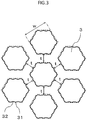
- FIG. 3 is an illustration of seven heat-radiating fins 3 of FIG. 2 as viewed in a direction perpendicular to the base 2.
- FIG. 4 is an enlarged view for illustrating one heat-radiating fin 3 of FIG. 3 .
- the heat-radiating fins 3 are each formed so that a sectional shape thereof along the base 2 is inscribed in a regular hexagon.
- the broken line indicates the regular hexagon circumscribed to the heat-radiating fin 3.
- a distance between facing sides of the regular hexagon circumscribed to one heat-radiating fin 3 is defined as an opposite side distance "w".
- the heat-radiating fin 3 has a projection-and-recess shape in cross section, which is inscribed in the regular hexagon.
- the heat-radiating fin 3 has projections 31 and recesses 32.
- the projections 31 are held in contact with the regular hexagon, and the recesses 32 are apart from the regular hexagon .
- the plurality of recesses 32 are arranged so as to be opposed to the sides of the regular hexagon. A distance between the side of the regular hexagon, which is circumscribed to the heat-radiating fin 3, and a common tangent of the plurality of recesses 32 opposed to the side and adjacent to each other is defined as a recess depth "a".
- the recess depth "a" is a distance between a bottom portion of the recess 32 of the projection-and-recess shape and the side of the regular hexagon, with which the projection 31 is held in contact.
- the broken line indicates a line obtained by extending one side of the regular hexagon, and the dashed-dotted line indicates the common tangent of the recesses 32 adjacent to each other.
- Six heat-radiating fins 3 are arranged around one heat-radiating fin 3.
- the six heat-radiating fins 3 are arrayed in a circumferential direction around the one heat-radiating fin 3 as a center.
- the respective sides of the regular hexagon, which are circumscribed to the one heat-radiating fin 3, are opposed to the respective sides of the regular hexagons, which are circumscribed to the respective heat-radiating fins 3 around the one heat-radiating fin 3.
- the sides of the regular hexagon, which are circumscribed to the one heat-radiating fin 3, and the sides of the regular hexagons, which are circumscribed to the respective six heat-radiating fins 3 arranged around the one heat-radiating fin 3, are apart from each other and are opposed to each other in an entire region.
- a distance between each of the sides of the regular hexagon, which are circumscribed to the one heat-radiating fin 3, and each of the sides of the regular hexagons circumscribed to the six heat-radiating fins 3 arranged around the one heat-radiating fin 3 is defined as a side-to-side distance "t".
- the root portion of the heat-radiating fin 3 maybe formed so as to have a corner R, in other words, to have roundness .
- the heat-radiating fin 3 may be formed into a tapered shape, which is tapered as separating from the base 2 in a perpendicular direction.
- the side-to-side distance "t" only needs to be a side-to-side distance "t” at an average height of the heat-radiating fins 3 each having a tapered shape.
- the average height is, for example, a height at an intermediate portion when the heat-radiating fin 3 is inclined linearly.
- the sides of the regular hexagons, which are circumscribed to the heat-radiating fins 3, are opposed to each other in an entire region at the side-to-side distance "t".
- the heat-radiating fins 3 are most densely arranged at the side-to-side distance "t” so that the surface area of the heat-radiating fins 3 is increased. Therefore, even when a limitation of a lower limit value of the side-to-side distance "t", which is imposed so as to prevent clogging of foreign matters such as dust, is set, the heat radiation performance of the heat sink can be enhanced within the limitations.
- refrigerant collides against the projections 31 of the projection-and-recess shape formed on each of side surfaces of the heat-radiating fin 3.
- a flow of the refrigerant is stirred, and a temperature boundary layer is thinned, thereby being capable of further enhancing the heat radiation performance of the heat sink.
- the heat-radiating fins 3 when the side-to-side distance "t" is fixed, as the opposite side distance "w” is larger, thermal resistance from the root to the distal end of each of the heat-radiating fins 3 is reduced. Thus, the entire side surfaces of the heat-radiating fins 3 can be used for heat radiation efficiently, that is, fin efficiency is enhanced. However, as the opposite side distance "w” is larger, the number of the heat-radiating fins 3 that can be arranged per unit area is reduced, which results in reduction in heat radiation area of the heat sink.
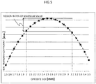
- FIG. 5 is a graph for showing a relationship between the opposite side distance "w" of the heat-radiating fin 3 and a heat transfer coefficient.
- the horizontal axis represents the opposite side distance "w” of the heat-radiating fin 3
- the vertical axis represents the heat transfer coefficient (freely selected unit).
- FIG. 5 there is shown a result of performing a three-dimensional thermal fluid simulation under a condition that the side-to-side distance "t", the recess depth "a", a height of the heat-radiating fin 3, and a refrigerant flow rate are fixed.
- the heat transfer coefficient becomes the maximum when the opposite side distance "w" is around 2.5 mm.
- the opposite side distance "w” is set to from 2.0 mm to 3.1 mm, 70% of the maximum value of the heat transfer coefficient can be obtained, thereby being capable of particularly enhancing the heat radiation performance of the heat sink.
- Configurations other than setting of the opposite side distance "w" to from 2.0 mm to 3.1 mm are the same as those of the first embodiment.
- the opposite side distance "w" is from 2.0 mm to 3.1 mm, thereby being capable of particularly enhancing the heat radiation performance.
- the flow of the refrigerant is further stirred at the projections 31 formed on the side surfaces of the heat-radiating fin 3, and an effect of thinning the temperature boundary layer is larger, which results in increase in heat radiation amount of the heat sink.
- the recess depth "a" of the heat-radiating fin 3 is larger, the refrigerant flow speed is lowered at the recesses 32 in the side surfaces of the heat-radiating fin 3, which results in reduction in heat radiation amount of the heat sink.
- the recess depth "a" of the heat-radiating fin 3 is smaller, stirring of the flow of the refrigerant is reduced at the projections 31 on the side surfaces, and the effect of thinning the temperature boundary layer is reduced, which results in reduction in heat radiation amount of the heat sink.
- the recess depth "a" of the heat-radiating fin 3 is smaller, lowering of the refrigerant flow speed is suppressed at the recesses 32 in the side surfaces of the heat-radiating fin 3, which results in increase in heat radiation amount of the heat sink.
- the effect of thinning the temperature boundary layer on the projections 31 and the refrigerant flow speed in the recesses 32 have a trade-off relation, and there is an optimum value for the recess depth "a".
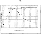
- FIG. 6 is a graph for showing a relationship between the recess depth "a” and a heat transfer coefficient.
- the horizontal axis represents the recess depth "a” of the heat-radiating fin 3
- the vertical axis represents the heat transfer coefficient (freely selected unit).
- FIG. 6 there is shown a result of performing a three-dimensional thermal fluid simulation under a condition that the side-to-side distance "t", the opposite side distance "w", a height of the heat-radiating fin 3, and a refrigerant flow rate are fixed.
- the heat transfer coefficient becomes the maximum when the recess depth "a" is around 0.1 mm.
- the recess depth "a” is set to from 0.05 mm to 0.15 mm, 70% of the maximum value of the heat transfer coefficient can be obtained, thereby being capable of particularly enhancing the heat radiation performance of the heat sink.
- Configurations other than the configuration that setting of the recess depth "a" to from 0.05 mm to 0.15 mm are the same as those of the first embodiment or the second embodiment.
- the recess depth "a" is from 0.05 mm to 0.15 mm, thereby being capable of particularly enhancing the heat radiation performance.
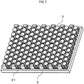
- FIG. 7 is a perspective view for illustrating heat-radiating fins and a base of a heat sink according to a fourth embodiment of the present invention.
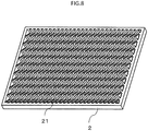
- FIG. 8 is a perspective view for illustrating the base in a state in which the heat-radiating fins are removed from the heat sink of FIG. 7 .
- a projection-and-recess portion 21 having a zig-zag shape is formed on the base 2. With the projection-and-recess portion 21 having a zig-zag shape, the flow of the refrigerant is stirred intricately when the refrigerant passes between the heat-radiating fins 3, a temperature boundary layer formed on the base 2 is thinned, and heat radiation of the heat sink is promoted.
- Other configurations are the same as those of the first embodiment to the third embodiment.
- the projection-and-recess portion 21 is formed on the base 2, and the projection-and-recess portion 21 is formed into a zig-zag shape.
- a temperature boundary layer formed on the base 2 can be thinned, thereby being capable of further promoting heat radiation.
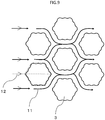
- FIG. 9 is a plan view for illustrating a plurality of heat-radiating fins in a heat sink according to a fifth embodiment of the present invention.
- the heat-radiating fins 3 as viewed in an axial direction of the heat-radiating fins 3 are illustrated.
- one heat-radiating fin 3 and six heat-radiating fins 3 provided around the one heat-radiating fin 3 are illustrated.
- a flow passage direction 11 of refrigerant passing between the adjacent heat-radiating fins 3 is indicated.
- the refrigerant passing through the heat sink flows in parallel to a straight line 12 connecting apexes of the regular hexagon circumscribed to the heat-radiating fin 3.
- the heat-radiating fins 3 are arranged so that the refrigerant flows along the straight line 12 connecting the apexes of the regular hexagon circumscribed to the heat-radiating fin 3.
- the straight line 12 connecting the apexes of the regular hexagon circumscribed to the heat-radiating fin 3 is a straight line 12 connecting the respective apexes of the regular hexagon circumscribed to the heat-radiating fin 3, that is, a pair of apexes opposed to each other.
- the refrigerant is caused to flow in parallel to the straight line connecting the apexes of the regular hexagon circumscribed to the heat-radiating fin 3.
- the side surfaces of the heat-radiating fins 3 can be used efficiently for heat radiation.
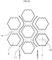
- FIG. 10 is an illustration of a state in which the refrigerant is caused to flow perpendicularly to the straight line connecting the apexes of the regular hexagon circumscribed to the heat-radiating fin 3.
- FIG. 10 when the refrigerant is caused to flow perpendicularly to the straight line connecting the apexes of the regular hexagon circumscribed to the heat-radiating fin 3, a stagnation region 13 of the refrigerant is generated in a direction orthogonal to the flow of the refrigerant. Sufficient heat radiation does not occur at the side surfaces of the heat-radiating fins 3 adjacent to the stagnation region 13 of the refrigerant.
- FIG. 10 is an illustration of a state in which the refrigerant is caused to flow perpendicularly to the straight line connecting the apexes of the regular hexagon circumscribed to the heat-radiating fin 3.
- the heat-radiating fins 3 are arranged so that the refrigerant flows in parallel to the straight line connecting the apexes of the regular hexagon circumscribed to the heat-radiating fin 3. Therefore, the stagnation region 13 of the refrigerant is not generated, thereby being capable of further enhancing the heat radiation performance of the heat sink.
Description
- The present invention relates to a heat sink configured to cool, for example, heat-generating elements.
- SiC is high in cost, and therefore, chip shrink is required for elements using SiC. As a result, heat generating density of the elements is increased, and the elements are increased in temperature. In view of this, a heat sink having high heat radiation performance has been demanded.
- The heat radiation performance of the heat sink is enhanced as a heat radiation area per unit volume of the heat-radiating fins of the heat sink is increased. The heat radiation area per unit volume of the heat-radiating fins is increased as a distance of a gap between the adj acent heat-radiating fins is smaller . However, in order to prevent clogging of foreign matters such as dust in the gap between the adjacent heat-radiating fins, a lower limit value is set for the distance of the gap between the adjacent heat-radiating fins depending on a usage environment of the heat sink in some cases. Therefore, increase in heat radiation area per unit volume of the heat-radiating fins within the limitation by the gap between the adj acent heat-radiating fins is a key for enhancing the heat radiation performance of the heat sink. Further, as a method for enhancing the heat radiation performance of the heat sink, there is given a method of thinning a temperature boundary layer formed on surfaces of the heat-radiating fins.
- Hitherto, there has been known a heat sink in which a plurality of heat-radiating fins each having a sectional shape of a regular hexagon are arrayed regularly. In this heat sink, in each of the heat-radiating fins, a side wall surface forming a first side of the regular hexagon and a side wall surface forming a fourth side opposed to the first side are arranged in parallel to each other along a first direction being an air direction. A side wall surface forming a second side and a side wall surface forming a fifth side opposed to the second side are arranged in parallel to each other along a second direction forming an angle with respect to the first direction between a second side adjacent to the first side of the regular hexagon and the first side. A side wall surface forming a sixth side and a side wall surface forming a third side opposed to the sixth side are arranged in parallel to each other along a third direction forming an angle with respect to the first direction between a sixth side adjacent to the first side of the regular hexagon and the first side. Further, in this heat sink, in each of the heat-radiating fins, for each of the first side to the sixth side of the regular hexagon, a side wall surface of the adjacent heat-radiating fin is arranged on an extended plane of each of the side wall surfaces. (for example, see Patent Literature 1) A heat sink according to the preamble of
claim 1 is known fromUS 6 729 383 B1 . - [PTL 1]
JP 3840970 B2 - However, in each of the heat-radiating fins, for each of the first side to the sixth side of the regular hexagon, the side wall surface of the adjacent heat-radiating fin is arranged on the extended plane of each of the side wall surfaces. Therefore, a space between the adjacent heat-radiating fins is increased. As a result, there is a problem in that the heat radiation area per unit volume of the heat-radiating fins is reduced, thereby degrading the heat radiation performance of the heat sink. Further, in each of the heat-radiating fins, the side wall surfaces are formed into flat surfaces. Therefore, there is a problem in that a temperature boundary layer formed on the surfaces of the heat-radiating fins is developed to be thick at the side wall surfaces of the heat-radiating fins, thereby degrading the heat radiation performance of the heat sink.
- The present invention provides a heat sink capable of enhancing the heat radiation performance while maintaining a lower limit value of a distance of a gap between adjacent heat-radiating fins.
- According to one embodiment of the present invention, there is provided a heat sink, including a plurality of heat-radiating fins provided on a base of the heat sink, wherein the heat-radiating fins each have a projection-and-recess shape in which a sectional shape along the base is inscribed in a regular hexagon, wherein projections of the projection-and-recess shape are held in contact with the regular hexagon, and wherein, in the adj acent heat-radiating fins, sides of the regular hexagon, with which the projections are held in contact, are opposed to each other in an entire region, and the heat-radiating fins are arranged so that side-to-side distances being distances between the sides opposed to each other at a distance are equal.
- In the heat sink according to one embodiment of the present invention, the heat-radiating fins each have the projection-and-recess shape in which the sectional shape along the base is inscribed in the regular hexagon. The projections of the projection-and-recess shape are held in contact with the regular hexagon. In the adjacent heat-radiating fins, the sides of the regular hexagon, with which the projections are held in contact, are opposed to each other in the entire region, and the heat-radiating fins are arranged so that the side-to-side distances being the distances between the sides opposed to each other at a distance are equal. With this, the heat radiation performance can be enhanced while maintaining the lower limit value of the distance of the gap between the adjacent heat-radiating fins.
-
-
FIG. 1 is an exploded perspective view for illustrating a heat sink according to a first embodiment of the present invention. -
FIG. 2 is a perspective view for illustrating heat-radiating fins and a base ofFIG. 1 . -
FIG. 3 is an illustration of seven heat-radiating fins ofFIG. 2 as viewed in a direction perpendicular to the base. -
FIG. 4 is an enlarged view for illustrating one heat-radiating fin ofFIG. 3 . -
FIG. 5 is a graph for showing a relationship between an opposite side distance of the heat-radiating fin and a heat transfer coefficient. -
FIG. 6 is a graph for showing a relationship between a recess depth and a heat transfer coefficient. -
FIG. 7 is a perspective view for illustrating heat-radiating fins and a base of a heat sink according to a fourth embodiment of the present invention. -
FIG. 8 is a perspective view for illustrating the base in a state in which the heat-radiating fins are removed from the heat sink ofFIG. 7 . -
FIG. 9 is a plan view for illustrating a plurality of heat-radiating fins in a heat sink according to a fifth embodiment of the present invention. -
FIG. 10 is an illustration of a state in which refrigerant is caused to flow perpendicularly to a straight line connecting apexes of a regular hexagon circumscribed to the heat-radiating fin. -
FIG. 1 is an exploded perspective view for illustrating a heat sink according to a first embodiment of the present invention. InFIG. 1 , the heat sink includes abase 2, a plurality of heat-radiatingfins 3, ajacket 4, arefrigerant inlet portion 5, and arefrigerant outlet portion 6. Thebase 2 has heat-generatingelements 1 provided on a top surface thereof. The plurality of heat-radiatingfins 3 are provided on a back surface of thebase 2. Thejacket 4 receives thebase 2 therein. Therefrigerant inlet portion 5 is provided on a side wall of thejacket 4. Therefrigerant outlet portion 6 is provided on a side wall of thejacket 4, which is opposed to the side wall on which therefrigerant inlet portion 5 is provided. - In the heat sink, refrigerant enters the
refrigerant inlet portion 5 in a direction indicated by the arrows A ofFIG. 1 . The refrigerant having entered therefrigerant inlet portion 5 passes through therefrigerant inlet portion 5 to enter a space defined by thejacket 4 and thebase 2. In this space, the refrigerant exchanges heat with the heat-radiatingfins 3 that receive heat from the heat-generatingelements 1. With this, the heat-generatingelements 1 are cooled by the heat-radiatingfins 3. The refrigerant having received heat through the heat exchange with the heat-radiatingfins 3 enters therefrigerant outlet portion 6 as it is. The refrigerant having entered therefrigerant outlet portion 6 passes through therefrigerant outlet portion 6 to be discharged to the outside of the heat sink. - The refrigerant to be used in the heat sink may be any of liquid, gas, and gas-liquid mixture. Further, the
jacket 4 may be omitted from the heat sink depending on an environment in which the heat sink is installed. -
FIG. 2 is a perspective view for illustrating the heat-radiatingfins 3 and thebase 2 ofFIG. 1 .FIG. 3 is an illustration of seven heat-radiatingfins 3 ofFIG. 2 as viewed in a direction perpendicular to thebase 2.FIG. 4 is an enlarged view for illustrating one heat-radiatingfin 3 ofFIG. 3 . The heat-radiatingfins 3 are each formed so that a sectional shape thereof along thebase 2 is inscribed in a regular hexagon. InFIG. 3 , the broken line indicates the regular hexagon circumscribed to the heat-radiatingfin 3. A distance between facing sides of the regular hexagon circumscribed to one heat-radiatingfin 3 is defined as an opposite side distance "w". - Further, the heat-radiating
fin 3 has a projection-and-recess shape in cross section, which is inscribed in the regular hexagon. The heat-radiatingfin 3 hasprojections 31 and recesses 32. Theprojections 31 are held in contact with the regular hexagon, and therecesses 32 are apart from the regular hexagon . The plurality ofrecesses 32 are arranged so as to be opposed to the sides of the regular hexagon. A distance between the side of the regular hexagon, which is circumscribed to the heat-radiatingfin 3, and a common tangent of the plurality ofrecesses 32 opposed to the side and adjacent to each other is defined as a recess depth "a". In other words, the recess depth "a" is a distance between a bottom portion of therecess 32 of the projection-and-recess shape and the side of the regular hexagon, with which theprojection 31 is held in contact. InFIG. 4 , the broken line indicates a line obtained by extending one side of the regular hexagon, and the dashed-dotted line indicates the common tangent of therecesses 32 adjacent to each other. - Six heat-radiating
fins 3 are arranged around one heat-radiatingfin 3. The six heat-radiatingfins 3 are arrayed in a circumferential direction around the one heat-radiatingfin 3 as a center. The respective sides of the regular hexagon, which are circumscribed to the one heat-radiatingfin 3, are opposed to the respective sides of the regular hexagons, which are circumscribed to the respective heat-radiatingfins 3 around the one heat-radiatingfin 3. - The sides of the regular hexagon, which are circumscribed to the one heat-radiating
fin 3, and the sides of the regular hexagons, which are circumscribed to the respective six heat-radiatingfins 3 arranged around the one heat-radiatingfin 3, are apart from each other and are opposed to each other in an entire region. A distance between each of the sides of the regular hexagon, which are circumscribed to the one heat-radiatingfin 3, and each of the sides of the regular hexagons circumscribed to the six heat-radiatingfins 3 arranged around the one heat-radiatingfin 3 is defined as a side-to-side distance "t". - The root portion of the heat-radiating
fin 3 maybe formed so as to have a corner R, in other words, to have roundness . Further, the heat-radiatingfin 3 may be formed into a tapered shape, which is tapered as separating from thebase 2 in a perpendicular direction. In this case, the side-to-side distance "t" only needs to be a side-to-side distance "t" at an average height of the heat-radiatingfins 3 each having a tapered shape. The average height is, for example, a height at an intermediate portion when the heat-radiatingfin 3 is inclined linearly. When outer peripheral portions of the plurality of arrayed heat-radiatingfins 3 interfere with a flow passage of refrigerant, due to a dimensional limitation, a shape limitation, and the like of the flow passage of the refrigerant, a part of each of the heat-radiatingfins 3, which is located at the outer peripheral portion, may be deformed so as to conform to the flow passage shape. - As described above, in the heat sink according to the first embodiment of the present invention, the sides of the regular hexagons, which are circumscribed to the heat-radiating
fins 3, are opposed to each other in an entire region at the side-to-side distance "t". Thus, the heat-radiatingfins 3 are most densely arranged at the side-to-side distance "t" so that the surface area of the heat-radiatingfins 3 is increased. Therefore, even when a limitation of a lower limit value of the side-to-side distance "t", which is imposed so as to prevent clogging of foreign matters such as dust, is set, the heat radiation performance of the heat sink can be enhanced within the limitations. Further, refrigerant collides against theprojections 31 of the projection-and-recess shape formed on each of side surfaces of the heat-radiatingfin 3. Thus, a flow of the refrigerant is stirred, and a temperature boundary layer is thinned, thereby being capable of further enhancing the heat radiation performance of the heat sink. - In the heat-radiating
fins 3, when the side-to-side distance "t" is fixed, as the opposite side distance "w" is larger, thermal resistance from the root to the distal end of each of the heat-radiatingfins 3 is reduced. Thus, the entire side surfaces of the heat-radiatingfins 3 can be used for heat radiation efficiently, that is, fin efficiency is enhanced. However, as the opposite side distance "w" is larger, the number of the heat-radiatingfins 3 that can be arranged per unit area is reduced, which results in reduction in heat radiation area of the heat sink. - Meanwhile, in the heat-radiating
fins 3, when the side-to-side distance "t" is fixed, as the opposite side distance "w" is smaller, thermal resistance from the root to the distal end of each of the heat-radiatingfins 3 is increased. Thus, as approaching the distal end of each of the heat-radiatingfins 3, a temperature is lowered, and the side surfaces of the heat-radiatingfins 3 only partially contribute to heat radiation, that is, the fin efficiency is degraded. However, as the opposite side distance "w" is smaller, the number of the heat-radiatingfins 3 that can be arranged per unit area is increased, which results in increase in heat radiation area of the heat sink. - As described above, in the heat-radiating
fins 3, under a condition that the side-to-side distance "t" is constant, depending on the opposite side distance "w", the efficiency of the heat radiation and the heat radiation area have a trade-off relation, and there is an optimum value for the opposite side distance "w". -
FIG. 5 is a graph for showing a relationship between the opposite side distance "w" of the heat-radiatingfin 3 and a heat transfer coefficient. InFIG. 5 , the horizontal axis represents the opposite side distance "w" of the heat-radiatingfin 3, and the vertical axis represents the heat transfer coefficient (freely selected unit). InFIG. 5 , there is shown a result of performing a three-dimensional thermal fluid simulation under a condition that the side-to-side distance "t", the recess depth "a", a height of the heat-radiatingfin 3, and a refrigerant flow rate are fixed. - As shown in
FIG. 5 , the heat transfer coefficient becomes the maximum when the opposite side distance "w" is around 2.5 mm. When the opposite side distance "w" is set to from 2.0 mm to 3.1 mm, 70% of the maximum value of the heat transfer coefficient can be obtained, thereby being capable of particularly enhancing the heat radiation performance of the heat sink. Configurations other than setting of the opposite side distance "w" to from 2.0 mm to 3.1 mm are the same as those of the first embodiment. - As described above, in the heat sink according to the second embodiment of the present invention, the opposite side distance "w" is from 2.0 mm to 3.1 mm, thereby being capable of particularly enhancing the heat radiation performance.
- As the recess depth "a" of the heat-radiating
fin 3 is larger, the flow of the refrigerant is further stirred at theprojections 31 formed on the side surfaces of the heat-radiatingfin 3, and an effect of thinning the temperature boundary layer is larger, which results in increase in heat radiation amount of the heat sink. However, as the recess depth "a" of the heat-radiatingfin 3 is larger, the refrigerant flow speed is lowered at therecesses 32 in the side surfaces of the heat-radiatingfin 3, which results in reduction in heat radiation amount of the heat sink. - Meanwhile, as the recess depth "a" of the heat-radiating
fin 3 is smaller, stirring of the flow of the refrigerant is reduced at theprojections 31 on the side surfaces, and the effect of thinning the temperature boundary layer is reduced, which results in reduction in heat radiation amount of the heat sink. However, as the recess depth "a" of the heat-radiatingfin 3 is smaller, lowering of the refrigerant flow speed is suppressed at therecesses 32 in the side surfaces of the heat-radiatingfin 3, which results in increase in heat radiation amount of the heat sink. - As described above, in the heat-radiating
fin 3, depending on the recess depth "a", the effect of thinning the temperature boundary layer on theprojections 31 and the refrigerant flow speed in therecesses 32 have a trade-off relation, and there is an optimum value for the recess depth "a". -
FIG. 6 is a graph for showing a relationship between the recess depth "a" and a heat transfer coefficient. InFIG. 6 , the horizontal axis represents the recess depth "a" of the heat-radiatingfin 3, and the vertical axis represents the heat transfer coefficient (freely selected unit). InFIG. 6 , there is shown a result of performing a three-dimensional thermal fluid simulation under a condition that the side-to-side distance "t", the opposite side distance "w", a height of the heat-radiatingfin 3, and a refrigerant flow rate are fixed. - As shown in
FIG. 6 , the heat transfer coefficient becomes the maximum when the recess depth "a" is around 0.1 mm. When the recess depth "a" is set to from 0.05 mm to 0.15 mm, 70% of the maximum value of the heat transfer coefficient can be obtained, thereby being capable of particularly enhancing the heat radiation performance of the heat sink. Configurations other than the configuration that setting of the recess depth "a" to from 0.05 mm to 0.15 mm are the same as those of the first embodiment or the second embodiment. - As described above, in the heat sink according to the third embodiment of the present invention, the recess depth "a" is from 0.05 mm to 0.15 mm, thereby being capable of particularly enhancing the heat radiation performance.
-
FIG. 7 is a perspective view for illustrating heat-radiating fins and a base of a heat sink according to a fourth embodiment of the present invention.FIG. 8 is a perspective view for illustrating the base in a state in which the heat-radiating fins are removed from the heat sink ofFIG. 7 . A projection-and-recess portion 21 having a zig-zag shape is formed on thebase 2. With the projection-and-recess portion 21 having a zig-zag shape, the flow of the refrigerant is stirred intricately when the refrigerant passes between the heat-radiatingfins 3, a temperature boundary layer formed on thebase 2 is thinned, and heat radiation of the heat sink is promoted. Other configurations are the same as those of the first embodiment to the third embodiment. - As described above, in the heat sink according to the fourth embodiment of the present invention, the projection-and-
recess portion 21 is formed on thebase 2, and the projection-and-recess portion 21 is formed into a zig-zag shape. Thus, a temperature boundary layer formed on thebase 2 can be thinned, thereby being capable of further promoting heat radiation. -
FIG. 9 is a plan view for illustrating a plurality of heat-radiating fins in a heat sink according to a fifth embodiment of the present invention. InFIG. 9 , the heat-radiatingfins 3 as viewed in an axial direction of the heat-radiatingfins 3 are illustrated. Further, inFIG. 9 , one heat-radiatingfin 3 and six heat-radiatingfins 3 provided around the one heat-radiatingfin 3 are illustrated. Further, inFIG. 9 , aflow passage direction 11 of refrigerant passing between the adjacent heat-radiatingfins 3 is indicated. InFIG. 9 , the refrigerant passing through the heat sink flows in parallel to astraight line 12 connecting apexes of the regular hexagon circumscribed to the heat-radiatingfin 3. In other words, the heat-radiatingfins 3 are arranged so that the refrigerant flows along thestraight line 12 connecting the apexes of the regular hexagon circumscribed to the heat-radiatingfin 3. In this case, thestraight line 12 connecting the apexes of the regular hexagon circumscribed to the heat-radiatingfin 3 is astraight line 12 connecting the respective apexes of the regular hexagon circumscribed to the heat-radiatingfin 3, that is, a pair of apexes opposed to each other. The refrigerant is caused to flow in parallel to the straight line connecting the apexes of the regular hexagon circumscribed to the heat-radiatingfin 3. With this, as compared to a case in which the refrigerant is caused to flow perpendicularly to the straight line connecting the apexes of the regular hexagon circumscribed to the heat-radiatingfin 3, the side surfaces of the heat-radiatingfins 3 can be used efficiently for heat radiation. -
FIG. 10 is an illustration of a state in which the refrigerant is caused to flow perpendicularly to the straight line connecting the apexes of the regular hexagon circumscribed to the heat-radiatingfin 3. As illustrated inFIG. 10 , when the refrigerant is caused to flow perpendicularly to the straight line connecting the apexes of the regular hexagon circumscribed to the heat-radiatingfin 3, astagnation region 13 of the refrigerant is generated in a direction orthogonal to the flow of the refrigerant. Sufficient heat radiation does not occur at the side surfaces of the heat-radiatingfins 3 adjacent to thestagnation region 13 of the refrigerant. In contrast, as illustrated inFIG. 9 , when the refrigerant is caused to flow in parallel to the straight line connecting the apexes of the regular hexagon circumscribed to the heat-radiatingfin 3, thestagnation region 13 of the refrigerant is not generated. Therefore, sufficient heat radiation can be caused to occur at all of the surfaces of the heat-radiatingfins 3, thereby being capable of enhancing the heat radiation performance of the heat sink. - As described above, in the heat sink according to the fifth embodiment of the present invention, the heat-radiating
fins 3 are arranged so that the refrigerant flows in parallel to the straight line connecting the apexes of the regular hexagon circumscribed to the heat-radiatingfin 3. Therefore, thestagnation region 13 of the refrigerant is not generated, thereby being capable of further enhancing the heat radiation performance of the heat sink.
Claims (5)
- A heat sink, comprising a plurality of heat-radiating fins (3) provided on a base (2) of the heat sink, characterised in that the heat-radiating fins (3) each have a projection-and-recess shape in which a sectional shape along the base (2) is inscribed in a regular hexagon,
wherein projections (31) of the projection-and-recess shape are held in contact with the regular hexagon, and
wherein, in the adjacent heat-radiating fins (3), sides of the regular hexagon, with which the projections (31) are held in contact, are opposed to each other in an entire region, and the heat-radiating fins (3) are arranged so that side-to-side distances being distances between the sides opposed to each other at a distance are equal. - A heat sink according to claim 1, wherein the opposite side distance being a distance between the opposing sides of the regular hexagons is from 2.0 mm to 3.1 mm.
- A heat sink according to claim 1 or 2, wherein a recess depth being a distance between a bottom portion of a recess (32) of the projection-and-recess shape and the side of the regular hexagon, with which the projection (31) is held in contact, is from 0.05 mm to 0.15 mm.
- A heat sink according to any one of claims 1 to 3,
wherein a projection-and-recess portion (21) is formed on a surface of the base (2), on which the heat-radiating fins (3) are provided, and
wherein the projection-and-recess portion (21) has a zig-zag shape. - A heat sink according to any one of claims 1 to 4, further comprising a refrigerant inlet portion (5) and refrigerant outlet portion (6), wherein the heat-radiating fins (3) and the refrigerant inlet and outlet portions are arranged so that refrigerant flows in parallel to a straight line connecting apexes of the regular hexagon.
Applications Claiming Priority (1)
| Application Number | Priority Date | Filing Date | Title |
|---|---|---|---|
| PCT/JP2016/063858 WO2017195270A1 (en) | 2016-05-10 | 2016-05-10 | Heat sink |
Publications (3)
| Publication Number | Publication Date |
|---|---|
| EP3457828A1 EP3457828A1 (en) | 2019-03-20 |
| EP3457828A4 EP3457828A4 (en) | 2019-05-22 |
| EP3457828B1 true EP3457828B1 (en) | 2021-04-07 |
Family
ID=60266434
Family Applications (1)
| Application Number | Title | Priority Date | Filing Date |
|---|---|---|---|
| EP16901619.3A Active EP3457828B1 (en) | 2016-05-10 | 2016-05-10 | Heat sink |
Country Status (5)
| Country | Link |
|---|---|
| US (1) | US10809017B2 (en) |
| EP (1) | EP3457828B1 (en) |
| JP (1) | JP6692417B2 (en) |
| CN (1) | CN109076716B (en) |
| WO (1) | WO2017195270A1 (en) |
Families Citing this family (9)
| Publication number | Priority date | Publication date | Assignee | Title |
|---|---|---|---|---|
| CN108024486A (en) * | 2018-01-04 | 2018-05-11 | 钦州学院 | Minitype radiator and its manufacture method based on dragonfly wing microcosmic surface |
| WO2020020619A1 (en) * | 2018-07-23 | 2020-01-30 | Siemens Aktiengesellschaft | Cooling components, converter and aircraft |
| JP6789335B2 (en) * | 2019-03-05 | 2020-11-25 | 三菱電機株式会社 | Heat sink and semiconductor module equipped with it |
| WO2021186891A1 (en) * | 2020-03-18 | 2021-09-23 | 富士電機株式会社 | Semiconductor module |
| JP2021197397A (en) * | 2020-06-10 | 2021-12-27 | 尼得科超▲しゅう▼科技股▲ふん▼有限公司 | Manufacturing method of heat sink |
| CN112188796B (en) * | 2020-09-07 | 2022-01-25 | 杭州电子科技大学 | High-power chip heat dissipation system and method with built-in small intestine villus-imitating micro needle ring |
| KR102378897B1 (en) * | 2020-10-19 | 2022-03-28 | 주식회사 고산 | Heat exchanger for battery and fuel cell stack |
| CN112377468A (en) * | 2020-11-06 | 2021-02-19 | 广州菲亚兰德科技有限公司 | Heat dissipation panel and heat dissipation equipment |
| CN115966531A (en) * | 2023-01-13 | 2023-04-14 | 广州小鹏汽车科技有限公司 | Heat dissipation system of power module |
Family Cites Families (36)
| Publication number | Priority date | Publication date | Assignee | Title |
|---|---|---|---|---|
| JPH04167549A (en) * | 1990-10-31 | 1992-06-15 | Matsushita Electric Ind Co Ltd | Semiconductor device |
| JPH07310998A (en) * | 1994-05-17 | 1995-11-28 | Kankyo Kagaku Kogyo Kk | Heat exchanger |
| JPH09138091A (en) | 1995-11-16 | 1997-05-27 | Rokuro Shimada | Radiating plate |
| JPH09162333A (en) * | 1995-12-07 | 1997-06-20 | Janome Sewing Mach Co Ltd | Heat sink for lsi |
| JPH09252066A (en) * | 1996-03-15 | 1997-09-22 | Mitsubishi Electric Corp | Heat sink |
| JP3431004B2 (en) * | 2000-01-14 | 2003-07-28 | 松下電器産業株式会社 | Heat sink and cooling device using the same |
| US6729383B1 (en) * | 1999-12-16 | 2004-05-04 | The United States Of America As Represented By The Secretary Of The Navy | Fluid-cooled heat sink with turbulence-enhancing support pins |
| JP3840970B2 (en) | 2001-12-18 | 2006-11-01 | 日本電気株式会社 | heatsink |
| JP2004103734A (en) | 2002-09-06 | 2004-04-02 | Furukawa Electric Co Ltd:The | Heat sink and method for manufacturing the same |
| US6919504B2 (en) * | 2002-12-19 | 2005-07-19 | 3M Innovative Properties Company | Flexible heat sink |
| US20070053168A1 (en) * | 2004-01-21 | 2007-03-08 | General Electric Company | Advanced heat sinks and thermal spreaders |
| JP4027353B2 (en) * | 2004-09-28 | 2007-12-26 | 三菱電機株式会社 | Cooling structure |
| CN100412495C (en) * | 2005-06-17 | 2008-08-20 | 周惠敏 | Heat exchanger with covering layer |
| TW200926945A (en) * | 2007-12-12 | 2009-06-16 | chong-xian Huang | Cylindrical heat dissipater equipped with cooling fins |
| EP3273161A1 (en) * | 2009-02-17 | 2018-01-24 | Epistar Corporation | Led light bulbs for space lighting |
| DE102010000875B4 (en) | 2010-01-13 | 2014-05-22 | Infineon Technologies Ag | Method for measuring the junction temperature of power semiconductors in a power converter |
| CN201688705U (en) * | 2010-03-05 | 2010-12-29 | 郑州安耐克实业有限公司 | Porous wave-shaped honeycomb checker brick |
| CN201894036U (en) * | 2010-11-19 | 2011-07-06 | 武汉热诺金属科技有限公司 | Honeycomb water-cooling radiator |
| JP5770519B2 (en) | 2011-04-20 | 2015-08-26 | 株式会社日本自動車部品総合研究所 | Cooling fin structure |
| JPWO2012157247A1 (en) * | 2011-05-16 | 2014-07-31 | 富士電機株式会社 | Semiconductor module cooler |
| JP2013138193A (en) | 2011-11-28 | 2013-07-11 | Kyocera Corp | Heat sink and electronic component device including the same |
| JP5878352B2 (en) | 2011-12-08 | 2016-03-08 | 昭和電工株式会社 | heatsink |
| FR3002646B1 (en) | 2013-02-22 | 2015-04-17 | Technofan | ELECTRONIC TEMPERATURE SENSOR FOR MEASURING THE JUNCTION TEMPERATURE OF AN ELECTRONIC POWER SWITCH IN OPERATION AND METHOD OF MEASURING THE TEMPERATURE OF JUNCTION BY THE ELECTRONIC SENSOR |
| US10986933B2 (en) * | 2013-03-15 | 2021-04-27 | Kryo, Inc. | Article comprising a temperature-conditioned surface, thermoelectric control unit, and method for temperature-conditioning the surface of an article |
| CN204084590U (en) * | 2014-10-09 | 2015-01-07 | 广东美的环境电器制造有限公司 | Oil spit of fland fin and electric heating installation using oil as medium |
| JP6271814B2 (en) * | 2014-10-20 | 2018-01-31 | フィリップス ライティング ホールディング ビー ヴィ | Lightweight tubular fin heat sink |
| US20160146405A1 (en) * | 2014-11-25 | 2016-05-26 | Posco Led Company Ltd. | Optical semiconductor lighting apparatus |
| JP6132869B2 (en) | 2015-04-07 | 2017-05-24 | 三菱電機株式会社 | heatsink |
| WO2016194158A1 (en) * | 2015-06-03 | 2016-12-08 | 三菱電機株式会社 | Liquid-cooled cooler, and manufacturing method for radiating fin in liquid-cooled cooler |
| CN104990051A (en) * | 2015-07-18 | 2015-10-21 | 朱大龙 | Radiator composed of large and small circular arc cooling fin arrays |
| US9638477B1 (en) * | 2015-10-13 | 2017-05-02 | Caterpillar, Inc. | Sealless cooling device having manifold and turbulator |
| WO2018003138A1 (en) * | 2016-07-01 | 2018-01-04 | かがつう株式会社 | Heat sink and electronic component package |
| US20180142964A1 (en) * | 2016-11-21 | 2018-05-24 | Abl Ip Holding Llc | Heatsink |
| US10415895B2 (en) * | 2016-11-21 | 2019-09-17 | Abl Ip Holding Llc | Heatsink |
| JP6462737B2 (en) * | 2017-01-24 | 2019-01-30 | 三菱電機株式会社 | heatsink |
| US20200008316A1 (en) * | 2018-06-28 | 2020-01-02 | Carbice Corporation | Flexible and conformable heat sinks and methods of making and using thereof |
-
2016
- 2016-05-10 JP JP2018516245A patent/JP6692417B2/en active Active
- 2016-05-10 EP EP16901619.3A patent/EP3457828B1/en active Active
- 2016-05-10 CN CN201680085387.2A patent/CN109076716B/en active Active
- 2016-05-10 US US16/093,727 patent/US10809017B2/en active Active
- 2016-05-10 WO PCT/JP2016/063858 patent/WO2017195270A1/en unknown
Non-Patent Citations (1)
| Title |
|---|
| None * |
Also Published As
| Publication number | Publication date |
|---|---|
| JP6692417B2 (en) | 2020-05-13 |
| US20190137195A1 (en) | 2019-05-09 |
| EP3457828A4 (en) | 2019-05-22 |
| JPWO2017195270A1 (en) | 2018-08-02 |
| CN109076716B (en) | 2020-10-27 |
| CN109076716A (en) | 2018-12-21 |
| EP3457828A1 (en) | 2019-03-20 |
| US10809017B2 (en) | 2020-10-20 |
| WO2017195270A1 (en) | 2017-11-16 |
Similar Documents
| Publication | Publication Date | Title |
|---|---|---|
| EP3457828B1 (en) | Heat sink | |
| CN107615479B (en) | Method for manufacturing radiating fin in liquid cooling cooler | |
| JP4776032B2 (en) | Heat exchanger | |
| CN110226365B (en) | Heat radiator | |
| US11502023B2 (en) | Semiconductor device with partition for refrigerant cooling | |
| JP2007096306A (en) | Heat sink | |
| US10809011B2 (en) | Heat sink | |
| JP2012216711A (en) | Heat sink and electronic component with the same | |
| CN111668177B (en) | Radiator and semiconductor module with same | |
| KR102296543B1 (en) | Liquid-cooled heat sink | |
| US20170280588A1 (en) | Heat dissipating device | |
| JP6138197B2 (en) | Liquid-cooled cooler and method of manufacturing radiating fin in liquid-cooled cooler | |
| EP3318832B1 (en) | Inner fin for heat exchanger | |
| JP6132869B2 (en) | heatsink | |
| WO2015114899A1 (en) | Cooling device and cooling device production method | |
| KR101163995B1 (en) | Oilcooler | |
| EP3023727B1 (en) | Fluid guide plate and associated plate heat exchanger | |
| CN114639647A (en) | Micro-channel heat dissipation structure and microelectronic chip structure | |
| JP7157591B2 (en) | heatsink | |
| CN215819168U (en) | Radiator and heat exchange device | |
| CN215956923U (en) | Radiator and heat exchange device | |
| CN215735489U (en) | Radiator and heat exchange device | |
| JP6868415B2 (en) | Heat sink for heat exchanger and heat exchanger | |
| US20210358834A1 (en) | Heat sink and heat exchanger | |
| CN215989620U (en) | Liquid cooling shell and laser |
Legal Events
| Date | Code | Title | Description |
|---|---|---|---|
| STAA | Information on the status of an ep patent application or granted ep patent |
Free format text: STATUS: THE INTERNATIONAL PUBLICATION HAS BEEN MADE |
|
| PUAI | Public reference made under article 153(3) epc to a published international application that has entered the european phase |
Free format text: ORIGINAL CODE: 0009012 |
|
| STAA | Information on the status of an ep patent application or granted ep patent |
Free format text: STATUS: REQUEST FOR EXAMINATION WAS MADE |
|
| 17P | Request for examination filed |
Effective date: 20181018 |
|
| AK | Designated contracting states |
Kind code of ref document: A1 Designated state(s): AL AT BE BG CH CY CZ DE DK EE ES FI FR GB GR HR HU IE IS IT LI LT LU LV MC MK MT NL NO PL PT RO RS SE SI SK SM TR |
|
| AX | Request for extension of the european patent |
Extension state: BA ME |
|
| A4 | Supplementary search report drawn up and despatched |
Effective date: 20190426 |
|
| RIC1 | Information provided on ipc code assigned before grant |
Ipc: H05K 7/20 20060101AFI20190418BHEP Ipc: F28F 3/12 20060101ALI20190418BHEP Ipc: F28D 21/00 20060101ALI20190418BHEP Ipc: F28F 3/02 20060101ALI20190418BHEP Ipc: F28F 3/04 20060101ALI20190418BHEP |
|
| DAV | Request for validation of the european patent (deleted) | ||
| DAX | Request for extension of the european patent (deleted) | ||
| GRAP | Despatch of communication of intention to grant a patent |
Free format text: ORIGINAL CODE: EPIDOSNIGR1 |
|
| STAA | Information on the status of an ep patent application or granted ep patent |
Free format text: STATUS: GRANT OF PATENT IS INTENDED |
|
| INTG | Intention to grant announced |
Effective date: 20201126 |
|
| GRAS | Grant fee paid |
Free format text: ORIGINAL CODE: EPIDOSNIGR3 |
|
| GRAA | (expected) grant |
Free format text: ORIGINAL CODE: 0009210 |
|
| STAA | Information on the status of an ep patent application or granted ep patent |
Free format text: STATUS: THE PATENT HAS BEEN GRANTED |
|
| AK | Designated contracting states |
Kind code of ref document: B1 Designated state(s): AL AT BE BG CH CY CZ DE DK EE ES FI FR GB GR HR HU IE IS IT LI LT LU LV MC MK MT NL NO PL PT RO RS SE SI SK SM TR |
|
| REG | Reference to a national code |
Ref country code: GB Ref legal event code: FG4D |
|
| REG | Reference to a national code |
Ref country code: AT Ref legal event code: REF Ref document number: 1381407 Country of ref document: AT Kind code of ref document: T Effective date: 20210415 Ref country code: CH Ref legal event code: EP |
|
| REG | Reference to a national code |
Ref country code: DE Ref legal event code: R096 Ref document number: 602016055911 Country of ref document: DE |
|
| REG | Reference to a national code |
Ref country code: IE Ref legal event code: FG4D |
|
| REG | Reference to a national code |
Ref country code: LT Ref legal event code: MG9D |
|
| REG | Reference to a national code |
Ref country code: NL Ref legal event code: MP Effective date: 20210407 Ref country code: AT Ref legal event code: MK05 Ref document number: 1381407 Country of ref document: AT Kind code of ref document: T Effective date: 20210407 |
|
| PG25 | Lapsed in a contracting state [announced via postgrant information from national office to epo] |
Ref country code: LT Free format text: LAPSE BECAUSE OF FAILURE TO SUBMIT A TRANSLATION OF THE DESCRIPTION OR TO PAY THE FEE WITHIN THE PRESCRIBED TIME-LIMIT Effective date: 20210407 Ref country code: FI Free format text: LAPSE BECAUSE OF FAILURE TO SUBMIT A TRANSLATION OF THE DESCRIPTION OR TO PAY THE FEE WITHIN THE PRESCRIBED TIME-LIMIT Effective date: 20210407 Ref country code: AT Free format text: LAPSE BECAUSE OF FAILURE TO SUBMIT A TRANSLATION OF THE DESCRIPTION OR TO PAY THE FEE WITHIN THE PRESCRIBED TIME-LIMIT Effective date: 20210407 Ref country code: BG Free format text: LAPSE BECAUSE OF FAILURE TO SUBMIT A TRANSLATION OF THE DESCRIPTION OR TO PAY THE FEE WITHIN THE PRESCRIBED TIME-LIMIT Effective date: 20210707 Ref country code: HR Free format text: LAPSE BECAUSE OF FAILURE TO SUBMIT A TRANSLATION OF THE DESCRIPTION OR TO PAY THE FEE WITHIN THE PRESCRIBED TIME-LIMIT Effective date: 20210407 Ref country code: NL Free format text: LAPSE BECAUSE OF FAILURE TO SUBMIT A TRANSLATION OF THE DESCRIPTION OR TO PAY THE FEE WITHIN THE PRESCRIBED TIME-LIMIT Effective date: 20210407 |
|
| PG25 | Lapsed in a contracting state [announced via postgrant information from national office to epo] |
Ref country code: RS Free format text: LAPSE BECAUSE OF FAILURE TO SUBMIT A TRANSLATION OF THE DESCRIPTION OR TO PAY THE FEE WITHIN THE PRESCRIBED TIME-LIMIT Effective date: 20210407 Ref country code: SE Free format text: LAPSE BECAUSE OF FAILURE TO SUBMIT A TRANSLATION OF THE DESCRIPTION OR TO PAY THE FEE WITHIN THE PRESCRIBED TIME-LIMIT Effective date: 20210407 Ref country code: NO Free format text: LAPSE BECAUSE OF FAILURE TO SUBMIT A TRANSLATION OF THE DESCRIPTION OR TO PAY THE FEE WITHIN THE PRESCRIBED TIME-LIMIT Effective date: 20210707 Ref country code: PT Free format text: LAPSE BECAUSE OF FAILURE TO SUBMIT A TRANSLATION OF THE DESCRIPTION OR TO PAY THE FEE WITHIN THE PRESCRIBED TIME-LIMIT Effective date: 20210809 Ref country code: PL Free format text: LAPSE BECAUSE OF FAILURE TO SUBMIT A TRANSLATION OF THE DESCRIPTION OR TO PAY THE FEE WITHIN THE PRESCRIBED TIME-LIMIT Effective date: 20210407 Ref country code: LV Free format text: LAPSE BECAUSE OF FAILURE TO SUBMIT A TRANSLATION OF THE DESCRIPTION OR TO PAY THE FEE WITHIN THE PRESCRIBED TIME-LIMIT Effective date: 20210407 Ref country code: GR Free format text: LAPSE BECAUSE OF FAILURE TO SUBMIT A TRANSLATION OF THE DESCRIPTION OR TO PAY THE FEE WITHIN THE PRESCRIBED TIME-LIMIT Effective date: 20210708 Ref country code: IS Free format text: LAPSE BECAUSE OF FAILURE TO SUBMIT A TRANSLATION OF THE DESCRIPTION OR TO PAY THE FEE WITHIN THE PRESCRIBED TIME-LIMIT Effective date: 20210807 |
|
| REG | Reference to a national code |
Ref country code: CH Ref legal event code: PL |
|
| REG | Reference to a national code |
Ref country code: DE Ref legal event code: R097 Ref document number: 602016055911 Country of ref document: DE |
|
| PG25 | Lapsed in a contracting state [announced via postgrant information from national office to epo] |
Ref country code: CH Free format text: LAPSE BECAUSE OF NON-PAYMENT OF DUE FEES Effective date: 20210531 Ref country code: DK Free format text: LAPSE BECAUSE OF FAILURE TO SUBMIT A TRANSLATION OF THE DESCRIPTION OR TO PAY THE FEE WITHIN THE PRESCRIBED TIME-LIMIT Effective date: 20210407 Ref country code: CZ Free format text: LAPSE BECAUSE OF FAILURE TO SUBMIT A TRANSLATION OF THE DESCRIPTION OR TO PAY THE FEE WITHIN THE PRESCRIBED TIME-LIMIT Effective date: 20210407 Ref country code: EE Free format text: LAPSE BECAUSE OF FAILURE TO SUBMIT A TRANSLATION OF THE DESCRIPTION OR TO PAY THE FEE WITHIN THE PRESCRIBED TIME-LIMIT Effective date: 20210407 Ref country code: MC Free format text: LAPSE BECAUSE OF FAILURE TO SUBMIT A TRANSLATION OF THE DESCRIPTION OR TO PAY THE FEE WITHIN THE PRESCRIBED TIME-LIMIT Effective date: 20210407 Ref country code: LU Free format text: LAPSE BECAUSE OF NON-PAYMENT OF DUE FEES Effective date: 20210510 Ref country code: LI Free format text: LAPSE BECAUSE OF NON-PAYMENT OF DUE FEES Effective date: 20210531 Ref country code: ES Free format text: LAPSE BECAUSE OF FAILURE TO SUBMIT A TRANSLATION OF THE DESCRIPTION OR TO PAY THE FEE WITHIN THE PRESCRIBED TIME-LIMIT Effective date: 20210407 Ref country code: RO Free format text: LAPSE BECAUSE OF FAILURE TO SUBMIT A TRANSLATION OF THE DESCRIPTION OR TO PAY THE FEE WITHIN THE PRESCRIBED TIME-LIMIT Effective date: 20210407 Ref country code: SM Free format text: LAPSE BECAUSE OF FAILURE TO SUBMIT A TRANSLATION OF THE DESCRIPTION OR TO PAY THE FEE WITHIN THE PRESCRIBED TIME-LIMIT Effective date: 20210407 Ref country code: SK Free format text: LAPSE BECAUSE OF FAILURE TO SUBMIT A TRANSLATION OF THE DESCRIPTION OR TO PAY THE FEE WITHIN THE PRESCRIBED TIME-LIMIT Effective date: 20210407 |
|
| REG | Reference to a national code |
Ref country code: BE Ref legal event code: MM Effective date: 20210531 |
|
| PLBE | No opposition filed within time limit |
Free format text: ORIGINAL CODE: 0009261 |
|
| STAA | Information on the status of an ep patent application or granted ep patent |
Free format text: STATUS: NO OPPOSITION FILED WITHIN TIME LIMIT |
|
| 26N | No opposition filed |
Effective date: 20220110 |
|
| GBPC | Gb: european patent ceased through non-payment of renewal fee |
Effective date: 20210707 |
|
| PG25 | Lapsed in a contracting state [announced via postgrant information from national office to epo] |
Ref country code: IE Free format text: LAPSE BECAUSE OF NON-PAYMENT OF DUE FEES Effective date: 20210510 Ref country code: GB Free format text: LAPSE BECAUSE OF NON-PAYMENT OF DUE FEES Effective date: 20210707 |
|
| PG25 | Lapsed in a contracting state [announced via postgrant information from national office to epo] |
Ref country code: IS Free format text: LAPSE BECAUSE OF FAILURE TO SUBMIT A TRANSLATION OF THE DESCRIPTION OR TO PAY THE FEE WITHIN THE PRESCRIBED TIME-LIMIT Effective date: 20210807 Ref country code: AL Free format text: LAPSE BECAUSE OF FAILURE TO SUBMIT A TRANSLATION OF THE DESCRIPTION OR TO PAY THE FEE WITHIN THE PRESCRIBED TIME-LIMIT Effective date: 20210407 |
|
| PG25 | Lapsed in a contracting state [announced via postgrant information from national office to epo] |
Ref country code: IT Free format text: LAPSE BECAUSE OF FAILURE TO SUBMIT A TRANSLATION OF THE DESCRIPTION OR TO PAY THE FEE WITHIN THE PRESCRIBED TIME-LIMIT Effective date: 20210407 Ref country code: BE Free format text: LAPSE BECAUSE OF NON-PAYMENT OF DUE FEES Effective date: 20210531 |
|
| P01 | Opt-out of the competence of the unified patent court (upc) registered |
Effective date: 20230512 |
|
| PG25 | Lapsed in a contracting state [announced via postgrant information from national office to epo] |
Ref country code: CY Free format text: LAPSE BECAUSE OF FAILURE TO SUBMIT A TRANSLATION OF THE DESCRIPTION OR TO PAY THE FEE WITHIN THE PRESCRIBED TIME-LIMIT Effective date: 20210407 |
|
| REG | Reference to a national code |
Ref country code: DE Ref legal event code: R084 Ref document number: 602016055911 Country of ref document: DE |
|
| PG25 | Lapsed in a contracting state [announced via postgrant information from national office to epo] |
Ref country code: HU Free format text: LAPSE BECAUSE OF FAILURE TO SUBMIT A TRANSLATION OF THE DESCRIPTION OR TO PAY THE FEE WITHIN THE PRESCRIBED TIME-LIMIT; INVALID AB INITIO Effective date: 20160510 |
|
| PGFP | Annual fee paid to national office [announced via postgrant information from national office to epo] |
Ref country code: FR Payment date: 20230411 Year of fee payment: 8 Ref country code: DE Payment date: 20230331 Year of fee payment: 8 |