JP3840970B2 - heatsink - Google Patents
heatsink Download PDFInfo
- Publication number
- JP3840970B2 JP3840970B2 JP2001384997A JP2001384997A JP3840970B2 JP 3840970 B2 JP3840970 B2 JP 3840970B2 JP 2001384997 A JP2001384997 A JP 2001384997A JP 2001384997 A JP2001384997 A JP 2001384997A JP 3840970 B2 JP3840970 B2 JP 3840970B2
- Authority
- JP
- Japan
- Prior art keywords
- wall surface
- side wall
- groove
- fin
- fins
- Prior art date
- Legal status (The legal status is an assumption and is not a legal conclusion. Google has not performed a legal analysis and makes no representation as to the accuracy of the status listed.)
- Expired - Fee Related
Links
- 238000005520 cutting process Methods 0.000 claims description 24
- 230000017525 heat dissipation Effects 0.000 description 9
- 239000000463 material Substances 0.000 description 5
- 239000000758 substrate Substances 0.000 description 5
- 229910052782 aluminium Inorganic materials 0.000 description 4
- XAGFODPZIPBFFR-UHFFFAOYSA-N aluminium Chemical compound [Al] XAGFODPZIPBFFR-UHFFFAOYSA-N 0.000 description 4
- 230000000694 effects Effects 0.000 description 4
- 229910052751 metal Inorganic materials 0.000 description 4
- 239000002184 metal Substances 0.000 description 4
- RYGMFSIKBFXOCR-UHFFFAOYSA-N Copper Chemical compound [Cu] RYGMFSIKBFXOCR-UHFFFAOYSA-N 0.000 description 3
- 230000000903 blocking effect Effects 0.000 description 3
- 229910052802 copper Inorganic materials 0.000 description 3
- 239000010949 copper Substances 0.000 description 3
- 238000004519 manufacturing process Methods 0.000 description 3
- 238000000034 method Methods 0.000 description 3
- 230000005855 radiation Effects 0.000 description 2
- 238000007664 blowing Methods 0.000 description 1
- 238000010586 diagram Methods 0.000 description 1
- 230000002093 peripheral effect Effects 0.000 description 1
Images


Classifications
-
- H—ELECTRICITY
- H01—ELECTRIC ELEMENTS
- H01L—SEMICONDUCTOR DEVICES NOT COVERED BY CLASS H10
- H01L2224/00—Indexing scheme for arrangements for connecting or disconnecting semiconductor or solid-state bodies and methods related thereto as covered by H01L24/00
- H01L2224/01—Means for bonding being attached to, or being formed on, the surface to be connected, e.g. chip-to-package, die-attach, "first-level" interconnects; Manufacturing methods related thereto
- H01L2224/26—Layer connectors, e.g. plate connectors, solder or adhesive layers; Manufacturing methods related thereto
- H01L2224/31—Structure, shape, material or disposition of the layer connectors after the connecting process
- H01L2224/32—Structure, shape, material or disposition of the layer connectors after the connecting process of an individual layer connector
- H01L2224/321—Disposition
- H01L2224/32151—Disposition the layer connector connecting between a semiconductor or solid-state body and an item not being a semiconductor or solid-state body, e.g. chip-to-substrate, chip-to-passive
- H01L2224/32221—Disposition the layer connector connecting between a semiconductor or solid-state body and an item not being a semiconductor or solid-state body, e.g. chip-to-substrate, chip-to-passive the body and the item being stacked
- H01L2224/32225—Disposition the layer connector connecting between a semiconductor or solid-state body and an item not being a semiconductor or solid-state body, e.g. chip-to-substrate, chip-to-passive the body and the item being stacked the item being non-metallic, e.g. insulating substrate with or without metallisation
Landscapes
- Cooling Or The Like Of Semiconductors Or Solid State Devices (AREA)
- Cooling Or The Like Of Electrical Apparatus (AREA)
Description
【0001】
【発明の属する技術分野】
本発明は、ヒートシンクに関し、特に、効率的な放熱を可能とするヒートシンクに関する。
【0002】
【従来の技術】
消費電力が大きく発熱量の多いLSI等のデバイスは、動作を保証する温度範囲を維持するために、効率よく放熱を行う必要がある。そのため、デバイスにアルミ等の放熱特性に優れたフィンを有するヒートシンクを取り付けるとともに、ヒートシンクにファンからの風を吹き付けることによって、デバイスを強制空冷することがある。
【0003】
【発明が解決しようとする課題】
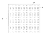
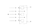
しかし、図5のように断面形状が四角形のピン型のフィンを並べた従来のヒートシンクの場合、図6に示すようにフィンの一面が風の流れを遮ってしまうため、十分な放熱が期待できないという問題がある。
【0004】
また、図7のように断面形状が流線形のピン型のフィンを並べたヒートシンクがある。しかし、この場合、フィンの形状が複雑になってしまうため、ヒートシンクを切削で製作する場合、非常に高価になってしまうという問題がある。
【0005】
本発明の第1の目的は、効率的な放熱を可能とするヒートシンクを提供することである。
【0006】
本発明の第2の目的は、低価格を実現するヒートシンクを提供することである。
【0007】
【課題を解決するための手段】
本発明の第1の視点においては、表面に複数のフィンを有するカバーを備えるヒートシンクにおいて、前記フィンは、一定間隔で規則的に配列するとともに、断面形状が正六角形であり、前記複数のフィンの配列は、風の流入方向である第1の方向に沿って、各フィンの正六角形の一の辺 ( 「第1の辺」という ) の側壁面と前記第1の辺に対向する他の辺 ( 「第4の辺」という ) の側壁面とが、平行に整列し、且つ、前記第1の方向に対して、各フィンの正六角形の前記第1の辺に隣接する第2の辺が前記第1の辺に対してなす角度の第2の方向に沿って、前記第2の辺の側壁面と前記第2の辺に対向する第5の辺の側壁面とが、平行に整列し、且つ、前記第1の方向に対して、各フィンの正六角形の前記第1の辺に隣接する第6の辺が前記第1の辺に対してなす角度の第3の方向に沿って、前記第6の辺の側壁面と前記第6の辺に対向する第3の辺の側壁面とが、平行に整列する、配置とされ、前記各フィンは、正六角形の第1乃至第6の辺の各々について、該辺の側壁面の延長面上に、隣の他のフィンにおける対応する辺の側壁面が位置付けられた構造を有し、前記第1の方向の風に当たるフィンではその側壁角部で前記風が前記第2及び第3の方向に分岐する、ことを特徴とする。
【0008】
本発明の第2の視点においては、表面に複数のフィンを有するカバーを備えるヒートシンクにおいて、前記フィンは、一定間隔で規則的に配列するとともに、各フィンの断面形状は六角形であり、前記複数のフィンの配列は、風の流入方向である第1の方向に沿って、各フィンの六角形の一の辺 ( 「第1の辺」という ) の側壁面と前記第1の辺に対向する他の辺 ( 「第4の辺」という ) の側壁面とが、平行に整列し、且つ、前記第1の方向に対して、各フィンの六角形の前記第1の辺に隣接する第2の辺が前記第1の辺に対してなす角度の第2の方向に沿って、前記第2の辺の側壁面と前記第2の辺に対向する第5の辺の側壁面とが、平行に整列し、且つ、前記第1の方向に対して、各フィンの六角形の前記第1の辺に隣接する第6の辺が前記第1の辺に対してなす角度の第3の方向に沿って、前記第6の辺の側壁面と前記第6の辺に対向する第3の辺の側壁面とが、平行に整列する、配置とされ、前記各フィンは、六角形の第1乃至第6の辺の各々について、該辺の側壁面の延長面上に、隣の他のフィンにおける対応する辺の側壁面が位置付けられた構造を有し、前記第1の方向の風に当たるフィンではその側壁角部で前記風が前記第2及び第3の方向に分岐する、ことを特徴とする。
【0009】
本発明の第3の視点においては、表面に複数のフィンを有するカバーを備えるヒートシンクにおいて、前記フィンは、一定間隔で規則的に配列するとともに、1つのフィンにつき平行関係にある2対の側壁面が3組存在し、かつ、一のフィンにおける側壁面の延長面上にその隣の他のフィンにおける側壁面が位置付けられた構造を有することを特徴とする。
【0010】
本発明の第4の視点においては、風の流入方向である第1の方向に沿って、板状部材に所定の間隔をおいて直線状かつ平行に形成された所定の幅を有する複数の第1の溝と、
前記板状部材に、前記第1の溝の側壁面に対して板面上において時計回りに0度より大きくかつ90度より小さい範囲の角度の第2の方向に沿って、所定の間隔をおいて直線状かつ平行に形成された所定の幅を有する複数の第2の溝と、前記板状部材に、前記第1の溝の側壁面に対して板面上において時計反対回りに0度より大きくかつ90度より小さい範囲の角度の第3の方向に沿って、所定の間隔をおいて直線状かつ平行に形成されるとともに、一の前記第1の溝とその隣の他の前記第1の溝との間で前記第2の溝の側壁面と交差する側壁面を有し、かつ、所定の幅を有する複数の第3の溝と、を有するカバーを備え、前記第1の方向の風に当たる前記第2の溝の側壁面と前記第3の溝の側壁面の交差部で前記風が前記第2及び第3の方向に分岐する、ことを特徴とする。
【0011】
また、前記ヒートシンクにおいて、前記第1の溝、前記第2の溝及び前記第3の溝のうち2以上について同じ幅であることが好ましい。
【0012】
また、前記ヒートシンクにおいて、前記第2の溝に係る角度と前記第3の溝に係る角度が同じであることが好ましい。
【0013】
また、前記ヒートシンクにおいて、前記第1の溝、前記第2の溝及び前記第3の溝は、それぞれ切削により形成されることが好ましい。
【0014】
【発明の実施の形態】
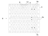
本発明は、表面に複数のフィン(図1の5、6)を有するカバー(図1の3)を備えるヒートシンクにおいて、前記フィン(図1の5、6)は、一定間隔で規則的に配列するとともに、各フィンの断面形状(平面に対し法線方向から見た時の形状)は正六角形であり、かつ、一のフィン(図2の5)における側壁面の延長面(図2の10)上にその隣の他のフィン(図2の6)における側壁面が位置付けられた構造を有することにより、ヒートシンク側方からの風は前記フィンの側壁角部に当たって分岐し、風の流れに対して垂直面となる側壁面を持たないので、風の流れを遮ることなくフィンの間を流通させることができる(図3参照)。
【0015】
【実施例】
本発明の実施例について図面を用いて説明する。図1は、本発明の実施例1に係るヒートシンクの構造を模式的に示した平面図及び断面図である。
【0016】
図1を参照すると、基板1は、表面に配線パターンを有する配線基板であり、板面中央近傍に電気的に接続する電子部品2を搭載しており、ベース7の枠内に配置されている。
【0017】
電子部品2は、LSI、IC等の発熱性の電子部品であり、基板1板面中央近傍に搭載されており、上側の放熱面に接触するように放熱材4が配されている。
【0018】
カバー3は、アルミ、銅等の放熱特性の優れた金属から構成されており、放熱材4の上面及びベース7の枠の端面に接触するように配されており、上面に一体かつ規則的に配された複数のフィン5、6を有する。
【0019】
放熱材4は、アルミ、銅等の放熱特性の優れた金属から構成されており、電子部品2上面とカバー3下面の間の両面に接触するように介在している。
【0020】
フィン5、6は、アルミ、銅等の放熱特性の優れた金属から構成されており、高さが揃った六角柱(断面は正六角形)であり、対向関係にある2対の側壁面は平行で、1本のフィンにつき平行となる2対の側壁面を3組備え、カバー3上面と一体に構成されており、一のフィン5における側壁面の延長線上に隣のフィン6における側壁面が位置付けられている。
【0021】
ベース7は、板面上面側の周縁部に枠部7aを有し、枠部7aと板面の間の角部に基板1を設置(実装)するための台部7bを有し、枠部7aの端面にカバー3の下面が接触している。
【0022】
次に、実施例1に係るヒートシンクにおけるカバー3上のフィン5の製造方法について説明する。図2は、本発明の実施例1に係るヒートシンクの製造方法を説明するために模式的に示した平面図である。
【0023】
まず、一定厚さの金属の板状体をフィン5の高さに相当する深さの溝を平面上の一方向(9a方向)に平行(かつ等間隔)に切削する。次に、同じ深さの溝を時計反対回り約60度の角度の方向(9b方向)に平行(かつ等間隔)に切削する。最後に、同じ深さの溝を時計回り約60度の角度の方向(9c方向)に平行(かつ等間隔)に切削する。
【0024】
ここで、一のフィン5は側壁面の延長線10上に他のフィン6の側壁面が位置付けられているので、図2に示すように3方向の削り角度9で加工することができる。
【0025】
次に、実施例1に係るヒートシンクにおける熱の流れについて図面を用いて説明する。
【0026】
図1の断面図を参照すると、電子部品2から発生した熱は、放熱材4を介してカバー3へ導かれる。カバー3へ導かれた熱は、カバー3及びフィン5から空気中へ放熱される。
【0027】
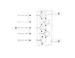
次に、実施例1に係るヒートシンク上の強制風の流れについて図面を用いて説明する。図3は、本発明の実施例1に係るヒートシンク上の強制風の流れを部分的に示した模式図である。
【0028】
図3を参照すると、強制風8は、ヒートシンクの側方からフィン5の側壁面に向かって吹き付けられており、各フィン5の側壁角部で2方向に分かれ、各フィン5の側壁面方向に沿って各フィン5間を流通し、最終的にはヒートシンク外に放出される。
【0029】
ここで、各フィン5は、強制風8の流れに対して垂直な側壁面を持たないので、風の流れを遮ることなく、各フィン5間を流通させることができる。
【0030】
次に、本発明の実施例2について図面を用いて説明する。図4は、本発明の実施例2に係るヒートシンクの構造を模式的に示した平面図である。
【0031】
図4を参照すると、フィン5の断面形状は、正六角形ではなく、平行となっている2対の辺を3組備える六角形となっている。フィン5を形成する工程において、3方向9a、9b、9cの削りのうち削り幅(溝の幅)、削り間隔若しくは削り角度(削り方向)を変えることによって、このような六角形を達成することができる。
【0032】
削り幅(溝の幅)を変える例として、1方向の削り幅を他の2方向の削り幅と変えるケース、あるいは、9a、9b、9cの3方向とも違う削り幅に変えるケースがある。
【0033】
削り間隔を変える例として、1方向の溝とその溝の間の間隔を他の2方向の溝とその溝の間の間隔を変えるケース、或いは、9a、9b、9cの3方向とも違う溝とその溝の間の間隔を変えるケースがある。
【0034】
削り角度を変える例として、基準となる一つの削り方向9aに対して他の2つの削り方向9b、9cを線対称となる角度(0度より大きく90度より小さい角度)にするケース、或いは、基準となる一つの削り方向9aに対して他の2つの削り方向9b、9cを非線対称となる角度(0度より大きく90度より小さい角度)にするケースがある。
【0035】
ここでは、各フィン5の断面は正六角形に限らず、1つのフィン5につき平行関係にある2対の側壁面が3組存在し、かつ、一のフィン5における側壁面の延長線上に隣のフィン6における側壁面が位置付けられた構造になっていればよい。
【0036】
本実施例によれば、実施例1と同様、風の流れを遮ることなくフィンの間を流通させることができるとともに、安価に製作できる。
【0037】
【発明の効果】
本発明によれば、以下のような効果を奏する。
【0038】
第1の効果は、従来の四角形状フィンに比べ放熱性を向上させることができることである。その理由は、風の流れに対して垂直面となる側壁面を持たないので、風の流れを遮ることなくフィンの間を流通させることができるためである。
【0039】
第2の効果は、安価に製作できることにある。その理由は、切削で正六角形フィンを製作する場合には、3方向の削り幅、間隔若しくは角度で加工できるからであり、フィンの断面形状を流線型状に切削加工するときのような複雑な動きを必要としないからである。
【図面の簡単な説明】
【図1】本発明の実施例1に係るヒートシンクの構造を模式的に示した平面図及び断面図である。
【図2】本発明の実施例1に係るヒートシンクの製造方法を説明するために模式的に示した平面図である。
【図3】本発明の実施例1に係るヒートシンク上の強制風の流れを部分的に示した模式図である。
【図4】本発明の実施例2に係るヒートシンクの構造を模式的に示した平面図である。
【図5】従来例1に係るヒートシンクの構造を模式的に示した平面図である。
【図6】従来例1に係るヒートシンク上の強制風の流れを部分的に示した模式図である。
【図7】従来例2に係るヒートシンクの構造を模式的に示した平面図である。
【符号の説明】
1 基板
2 電子部品
3 カバー
4 放熱材
5、6 フィン
7 ベース
7a 枠部
7b 台部
8 強制風の流れ
9a、9b、9c 切削削り方向
10 延長線
11 従来例1のフィン(四角形)
12 従来例2のフィン(流線形)[0001]
BACKGROUND OF THE INVENTION
The present invention relates to a heat sink, and more particularly, to a heat sink that enables efficient heat dissipation.
[0002]
[Prior art]
Devices such as LSIs that consume large amounts of power and generate a large amount of heat must efficiently dissipate heat in order to maintain a temperature range that guarantees operation. For this reason, the device may be forcibly air-cooled by attaching a heat sink having fins with excellent heat dissipation characteristics such as aluminum to the device and blowing air from the fan to the heat sink.
[0003]
[Problems to be solved by the invention]
However, in the case of the conventional heat sink in which pin-shaped fins having a square cross-sectional shape are arranged as shown in FIG. 5, since one surface of the fin blocks the flow of wind as shown in FIG. 6, sufficient heat radiation cannot be expected. There is a problem.
[0004]
Further, as shown in FIG. 7, there is a heat sink in which pin-shaped fins having a streamlined cross section are arranged. However, in this case, since the shape of the fin becomes complicated, there is a problem that when the heat sink is manufactured by cutting, it becomes very expensive.
[0005]
A first object of the present invention is to provide a heat sink that enables efficient heat dissipation.
[0006]
The second object of the present invention is to provide a heat sink that achieves low cost.
[0007]
[Means for Solving the Problems]
In a first aspect of the present invention, the heat sink comprises a cover having a plurality of fins on a surface, the fin is configured to regularly arranged at regular intervals, a regular hexagonal cross-sectional shape, said plurality of fins The arrangement is such that the side wall surface of one side of the regular hexagon of each fin (referred to as “first side” ) and the other side facing the first side along the first direction, which is the wind inflow direction And a second side adjacent to the first side of the regular hexagon of each fin with respect to the first direction is aligned in parallel with the side wall surface (referred to as “fourth side” ). A side wall surface of the second side and a side wall surface of the fifth side facing the second side are aligned in parallel along the second direction of the angle formed with respect to the first side. And a sixth side adjacent to the first side of the regular hexagon of each fin with respect to the first direction is the first side. A side wall surface of the sixth side and a side wall surface of the third side opposite to the sixth side are arranged in parallel along a third direction of an angle formed with respect to the side. Each of the fins has a structure in which, for each of the first to sixth sides of the regular hexagon, the side wall surface of the corresponding side in the other fins is positioned on the extended surface of the side wall surface of the side. In the fin that hits the wind in the first direction, the wind branches in the second and third directions at the corners of the side walls.
[0008]
In a second aspect of the present invention, the heat sink comprises a cover having a plurality of fins on a surface, the fin is configured to regularly arranged at regular intervals, the cross-sectional shape of each fin is hexagonal, the plurality The arrangement of the fins faces the first hexagonal side wall surface of each fin (referred to as “first side” ) and the first side along the first direction which is the wind inflow direction. A second side adjacent to the first side of the hexagon of each fin with respect to the first direction with respect to the side wall surface of the other side (referred to as “fourth side” ) A side wall surface of the second side and a side wall surface of the fifth side facing the second side are parallel to each other along a second direction of an angle formed by the side of the first side with respect to the first side. And the sixth side adjacent to the first side of the hexagonal shape of each fin is the first direction with respect to the first direction. An arrangement in which a side wall surface of the sixth side and a side wall surface of the third side opposite to the sixth side are aligned in parallel along a third direction of an angle formed with respect to the side of Each of the fins has a structure in which, for each of the first to sixth sides of the hexagon, the side wall surface of the corresponding side in the adjacent other fin is positioned on the extended surface of the side wall surface of the side. a, wherein the air in the first fin which corresponds to the wind direction at the sidewall angle portion is branched into the second and third direction, and wherein the.
[0009]
In a third aspect of the present invention, in a heat sink including a cover having a plurality of fins on the surface, the fins are regularly arranged at regular intervals, and two pairs of side wall surfaces are parallel to each other. There are three sets, and the side wall surface of another fin adjacent thereto is positioned on the extended surface of the side wall surface of one fin.
[0010]
In a fourth aspect of the present invention, a plurality of first widths having a predetermined width formed linearly and in parallel with the plate-like member at predetermined intervals along the first direction which is the wind inflow direction . 1 groove,
The plate-like member is spaced apart from the side wall surface of the first groove by a predetermined interval along a second direction having an angle in the range of greater than 0 degrees and less than 90 degrees clockwise on the plate surface. A plurality of second grooves having a predetermined width formed in a straight line and in parallel, and the plate-like member from 0 degrees clockwise on the plate surface with respect to the side wall surface of the first groove. The first groove is formed linearly and in parallel with a predetermined interval along a third direction having an angle in a range larger and smaller than 90 degrees, and the first groove and the other first adjacent to the first groove. A cover having a sidewall surface intersecting with the sidewall surface of the second groove and a plurality of third grooves having a predetermined width . The second and third directions of the second and third winds at the intersection of the side wall surface of the second groove that hits the wind and the side wall surface of the third groove Branches to, characterized in that.
[0011]
In the heat sink, it is preferable that two or more of the first groove, the second groove, and the third groove have the same width.
[0012]
In the heat sink, it is preferable that an angle related to the second groove and an angle related to the third groove are the same.
[0013]
In the heat sink, it is preferable that the first groove, the second groove, and the third groove are formed by cutting.
[0014]
DETAILED DESCRIPTION OF THE INVENTION
The present invention provides a heat sink including a cover (3 in FIG. 1) having a plurality of fins (5 and 6 in FIG. 1) on the surface, wherein the fins (5 and 6 in FIG. 1) are regularly arranged at regular intervals. In addition, the cross-sectional shape of each fin (the shape when viewed from the normal direction with respect to the plane) is a regular hexagon, and the extended side surface (10 in FIG. 2) of one fin (5 in FIG. 2). ) Has a structure in which the side wall surface of another fin (6 in FIG. 2) adjacent thereto is positioned on the top, the wind from the side of the heat sink diverges against the corner of the side wall of the fin, and the flow of the wind In addition, since it does not have a vertical side wall surface, it is possible to circulate between the fins without blocking the flow of the wind (see FIG. 3).
[0015]
【Example】
Embodiments of the present invention will be described with reference to the drawings. 1A and 1B are a plan view and a cross-sectional view schematically showing the structure of a heat sink according to Embodiment 1 of the present invention.
[0016]
Referring to FIG. 1, a substrate 1 is a wiring substrate having a wiring pattern on the surface, and an electronic component 2 that is electrically connected is mounted in the vicinity of the center of the plate surface, and is disposed within a frame of the base 7. .
[0017]
The electronic component 2 is a heat-generating electronic component such as an LSI or an IC, and is mounted near the center of the plate surface of the substrate 1, and a heat dissipation material 4 is disposed so as to contact the upper heat dissipation surface.
[0018]
The
[0019]
The heat dissipating material 4 is made of a metal having excellent heat dissipating characteristics such as aluminum and copper, and is interposed so as to contact both surfaces between the upper surface of the electronic component 2 and the lower surface of the
[0020]
The
[0021]
The base 7 has a frame portion 7a at the peripheral portion on the upper surface side of the plate surface, and has a
[0022]
Next, a method for manufacturing the
[0023]
First, a metal plate having a certain thickness is cut into a groove having a depth corresponding to the height of the
[0024]
Here, since the side wall surface of the other fin 6 is positioned on the
[0025]
Next, the heat flow in the heat sink according to the first embodiment will be described with reference to the drawings.
[0026]
Referring to the cross-sectional view of FIG. 1, the heat generated from the electronic component 2 is guided to the
[0027]
Next, the flow of forced air on the heat sink according to the first embodiment will be described with reference to the drawings. FIG. 3 is a schematic diagram partially showing the flow of forced air on the heat sink according to the first embodiment of the present invention.
[0028]
Referring to FIG. 3, the forced
[0029]
Here, since each
[0030]
Next, Embodiment 2 of the present invention will be described with reference to the drawings. FIG. 4 is a plan view schematically showing the structure of the heat sink according to the second embodiment of the present invention.
[0031]
Referring to FIG. 4, the cross-sectional shape of the
[0032]
As an example of changing the cutting width (groove width), there are a case where the cutting width in one direction is changed to the cutting width in the other two directions, or a case where the cutting width is changed to a cutting width different from the three
[0033]
As an example of changing the cutting interval, a case where the interval between the groove in one direction and the groove is changed between the other two directions and the groove, or a groove which is different from the three
[0034]
As an example of changing the cutting angle, a case where the other two cutting
[0035]
Here, the cross-section of each
[0036]
According to the present embodiment, similar to the first embodiment, it is possible to circulate between the fins without blocking the flow of the wind, and it can be manufactured at a low cost.
[0037]
【The invention's effect】
According to the present invention, the following effects can be obtained.
[0038]
The first effect is that heat dissipation can be improved as compared with the conventional rectangular fin. The reason is that since there is no side wall surface that is a vertical plane with respect to the wind flow, it is possible to circulate between the fins without blocking the wind flow.
[0039]
The second effect is that it can be manufactured at low cost. The reason is that when a regular hexagonal fin is manufactured by cutting, it can be processed with a cutting width, interval, or angle in three directions, and the complicated movement as when cutting the cross-sectional shape of the fin into a streamline shape is performed. It is because it does not need.
[Brief description of the drawings]
1A and 1B are a plan view and a cross-sectional view schematically showing the structure of a heat sink according to Embodiment 1 of the present invention.
FIG. 2 is a plan view schematically illustrating the method for manufacturing a heat sink according to the first embodiment of the invention.
FIG. 3 is a schematic view partially showing the flow of forced air on the heat sink according to the first embodiment of the present invention.
FIG. 4 is a plan view schematically showing the structure of a heat sink according to Embodiment 2 of the present invention.
5 is a plan view schematically showing the structure of a heat sink according to Conventional Example 1. FIG.
6 is a schematic view partially showing the flow of forced air on a heat sink according to Conventional Example 1. FIG.
7 is a plan view schematically showing the structure of a heat sink according to Conventional Example 2. FIG.
[Explanation of symbols]
DESCRIPTION OF SYMBOLS 1 Board | substrate 2
12 Fin of conventional example 2 (streamline)
Claims (6)
前記フィンは、一定間隔で規則的に配列するとともに、断面形状が正六角形であり、
前記複数のフィンの配列は、
風の流入方向である第1の方向に沿って、各フィンの正六角形の一の辺 ( 「第1の辺」という ) の側壁面と前記第1の辺に対向する他の辺 ( 「第4の辺」という ) の側壁面とが、平行に整列し、且つ、
前記第1の方向に対して、各フィンの正六角形の前記第1の辺に隣接する第2の辺が前記第1の辺に対してなす角度の第2の方向に沿って、前記第2の辺の側壁面と前記第2の辺に対向する第5の辺の側壁面とが、平行に整列し、且つ、
前記第1の方向に対して、各フィンの正六角形の前記第1の辺に隣接する第6の辺が前記第1の辺に対してなす角度の第3の方向に沿って、前記第6の辺の側壁面と前記第6の辺に対向する第3の辺の側壁面とが、平行に整列する、配置とされ、
前記各フィンは、正六角形の第1乃至第6の辺の各々について、該辺の側壁面の延長面上に、隣の他のフィンにおける対応する辺の側壁面が位置付けられた構造を有し、
前記第1の方向の風に当たるフィンではその側壁角部で前記風が前記第2及び第3の方向に分岐する、ことを特徴とするヒートシンク。In a heat sink comprising a cover having a plurality of fins on the surface,
The fins are regularly arranged at regular intervals, and the cross-sectional shape is a regular hexagon,
The arrangement of the plurality of fins is:
Along the first direction, which is the wind inflow direction, the side wall surface of one side of the regular hexagon of each fin (referred to as “first side” ) and the other side ( “first side ” facing the first side ) And the side wall surface of 4 side ) are aligned in parallel, and
The second side adjacent to the first side of the regular hexagon of each fin with respect to the first direction is along a second direction of an angle formed with respect to the first side by the second side. And the side wall surface of the fifth side opposite to the second side are aligned in parallel, and
The sixth side adjacent to the first side of the regular hexagon of each fin with respect to the first direction along the third direction of the angle formed by the first side with respect to the first side; The side wall surface of the side and the side wall surface of the third side facing the sixth side are arranged in parallel,
Each of the fins has a structure in which, for each of the first to sixth sides of the regular hexagon, a side wall surface of a corresponding side in another adjacent fin is positioned on an extended surface of the side wall surface of the side. ,
The heat sink , wherein the wind branches in the second and third directions at the corners of the side walls of the fins that hit the wind in the first direction .
前記フィンは、一定間隔で規則的に配列するとともに、断面形状が六角形であり、
前記複数のフィンの配列は、
風の流入方向である第1の方向に沿って、各フィンの六角形の一の辺 ( 「第1の辺」という ) の側壁面と前記第1の辺に対向する他の辺 ( 「第4の辺」という ) の側壁面とが、平行に整列し、且つ、
前記第1の方向に対して、各フィンの六角形の前記第1の辺に隣接する第2の辺が前記第1の辺に対してなす角度の第2の方向に沿って、前記第2の辺の側壁面と前記第2の辺に対向する第5の辺の側壁面とが、平行に整列し、且つ、
前記第1の方向に対して、各フィンの六角形の前記第1の辺に隣接する第6の辺が前記第1の辺に対してなす角度の第3の方向に沿って、前記第6の辺の側壁面と前記第6の辺に対向する第3の辺の側壁面とが、平行に整列する、配置とされ、
前記各フィンは、六角形の第1乃至第6の辺の各々について、該辺の側壁面の延長面上に、隣の他のフィンにおける対応する辺の側壁面が位置付けられた構造を有し、
前記第1の方向の風に当たるフィンではその側壁角部で前記風が前記第2及び第3の方向に分岐する、ことを特徴とするヒートシンク。In a heat sink comprising a cover having a plurality of fins on the surface,
The fins are regularly arranged at regular intervals, and the cross-sectional shape is hexagonal,
The arrangement of the plurality of fins is:
Along a first direction which is the inflow direction of the wind, the other side ( "the opposite side wall surface and the first side of one side of the hexagon of each fin (referred to as" first side ") And the side wall surface of 4 side ) are aligned in parallel, and
The second side of the second side adjacent to the first side of the hexagonal shape of each fin along the second direction of the angle formed with respect to the first side with respect to the first direction. And the side wall surface of the fifth side opposite to the second side are aligned in parallel, and
The sixth side adjacent to the first side of the hexagon of each fin with respect to the first direction along a third direction of an angle formed by the first side with respect to the first side; The side wall surface of the side and the side wall surface of the third side facing the sixth side are arranged in parallel,
Each of the fins has a structure in which, for each of the first to sixth sides of the hexagon, a side wall surface of a corresponding side in another adjacent fin is positioned on an extended surface of the side wall surface of the side. ,
The heat sink , wherein the wind branches in the second and third directions at the corners of the side walls of the fins that hit the wind in the first direction .
前記板状部材に、前記第1の溝の側壁面に対して板面上において時計回りに0度より大きくかつ90度より小さい範囲の角度の第2の方向に沿って、所定の間隔をおいて直線状かつ平行に形成された所定の幅を有する複数の第2の溝と、
前記板状部材に、前記第1の溝の側壁面に対して板面上において時計反対回りに0度より大きくかつ90度より小さい範囲の角度の第3の方向に沿って、所定の間隔をおいて直線状かつ平行に形成されるとともに、一の前記第1の溝とその隣の他の前記第1の溝との間で前記第2の溝の側壁面と交差する側壁面を有し、かつ、所定の幅を有する複数の第3の溝と、を有するカバーを備え、
前記第1の方向の風に当たる前記第2の溝の側壁面と前記第3の溝の側壁面の交差部で前記風が前記第2及び第3の方向に分岐する、ことを特徴とするヒートシンク。A plurality of first grooves having a predetermined width formed linearly and in parallel with a predetermined interval in the plate-like member along a first direction which is an inflow direction of the wind ;
The plate-like member is spaced apart from the side wall surface of the first groove by a predetermined interval along a second direction having an angle in the range of greater than 0 degrees and less than 90 degrees clockwise on the plate surface. A plurality of second grooves having a predetermined width formed in a straight line and in parallel;
A predetermined interval is provided on the plate-like member along a third direction of an angle in a range greater than 0 degrees and less than 90 degrees clockwise on the plate surface with respect to the side wall surface of the first groove. And a side wall surface that intersects with the side wall surface of the second groove between the one first groove and the other adjacent first groove. And a cover having a plurality of third grooves having a predetermined width,
The heat sink is characterized in that the wind branches in the second and third directions at the intersection of the side wall surface of the second groove and the side wall surface of the third groove that strikes the wind in the first direction. .
Priority Applications (1)
| Application Number | Priority Date | Filing Date | Title |
|---|---|---|---|
| JP2001384997A JP3840970B2 (en) | 2001-12-18 | 2001-12-18 | heatsink |
Applications Claiming Priority (1)
| Application Number | Priority Date | Filing Date | Title |
|---|---|---|---|
| JP2001384997A JP3840970B2 (en) | 2001-12-18 | 2001-12-18 | heatsink |
Publications (2)
| Publication Number | Publication Date |
|---|---|
| JP2003188322A JP2003188322A (en) | 2003-07-04 |
| JP3840970B2 true JP3840970B2 (en) | 2006-11-01 |
Family
ID=27594584
Family Applications (1)
| Application Number | Title | Priority Date | Filing Date |
|---|---|---|---|
| JP2001384997A Expired - Fee Related JP3840970B2 (en) | 2001-12-18 | 2001-12-18 | heatsink |
Country Status (1)
| Country | Link |
|---|---|
| JP (1) | JP3840970B2 (en) |
Cited By (2)
| Publication number | Priority date | Publication date | Assignee | Title |
|---|---|---|---|---|
| JP2016225555A (en) * | 2015-06-03 | 2016-12-28 | 三菱電機株式会社 | Liquid-cooling cooler and manufacturing method of heat radiation fins in the same |
| CN109076716A (en) * | 2016-05-10 | 2018-12-21 | 三菱电机株式会社 | Radiator |
Families Citing this family (5)
| Publication number | Priority date | Publication date | Assignee | Title |
|---|---|---|---|---|
| JP2005327795A (en) * | 2004-05-12 | 2005-11-24 | Sumitomo Electric Ind Ltd | Radiator |
| JP4623646B2 (en) * | 2004-05-27 | 2011-02-02 | ホーチキ株式会社 | CATV amplifier |
| JP5770519B2 (en) * | 2011-04-20 | 2015-08-26 | 株式会社日本自動車部品総合研究所 | Cooling fin structure |
| JP6441033B2 (en) * | 2014-11-10 | 2018-12-19 | ダイヤモンド電機株式会社 | heatsink |
| CN115966531A (en) * | 2023-01-13 | 2023-04-14 | 广州小鹏汽车科技有限公司 | Heat dissipation system of power module |
-
2001
- 2001-12-18 JP JP2001384997A patent/JP3840970B2/en not_active Expired - Fee Related
Cited By (4)
| Publication number | Priority date | Publication date | Assignee | Title |
|---|---|---|---|---|
| JP2016225555A (en) * | 2015-06-03 | 2016-12-28 | 三菱電機株式会社 | Liquid-cooling cooler and manufacturing method of heat radiation fins in the same |
| CN109076716A (en) * | 2016-05-10 | 2018-12-21 | 三菱电机株式会社 | Radiator |
| US10809017B2 (en) | 2016-05-10 | 2020-10-20 | Mitsubishi Electric Corporation | Heat sink with projection and recess shaped fins |
| CN109076716B (en) * | 2016-05-10 | 2020-10-27 | 三菱电机株式会社 | Heat radiator |
Also Published As
| Publication number | Publication date |
|---|---|
| JP2003188322A (en) | 2003-07-04 |
Similar Documents
| Publication | Publication Date | Title |
|---|---|---|
| US6967845B2 (en) | Integrated heat dissipating device with curved fins | |
| JP3269397B2 (en) | Printed wiring board | |
| CN102415229B (en) | Electronic device cooling structure | |
| KR100294873B1 (en) | LS Eye Package Cooling Wave Heat Sink Assembly | |
| US7040388B1 (en) | Heat sink, method of manufacturing the same and cooling apparatus using the same | |
| US6269864B1 (en) | Parallel-plate/pin-fin hybrid copper heat sink for cooling high-powered microprocessors | |
| US6397926B1 (en) | Heat sink, method manufacturing the same and cooling apparatus using the same | |
| US6446708B1 (en) | Heat dissipating device | |
| US6533028B2 (en) | Heat sink, method of manufacturing the same, and cooling apparatus using the same | |
| US6479895B1 (en) | High performance air cooled heat sinks used in high density packaging applications | |
| US20060175045A1 (en) | Heat dissipation device | |
| US20050150637A1 (en) | Heat sink and multi-directional passages thereof | |
| JP2003142637A (en) | Heat sink and heating element cooling structure | |
| JP3840970B2 (en) | heatsink | |
| JP6883498B2 (en) | Heatsink | |
| WO2009157080A1 (en) | Power supply unit | |
| CN110739283A (en) | kinds of radiator | |
| JP2000283670A (en) | Heat sink | |
| CN2518146Y (en) | Heat sink for improved cooling efficiency | |
| JP2010287730A (en) | Heat receiving surface parallel-fin type flat heat dissipation structure | |
| JPH0412559A (en) | Cooling structure for electronic equipment | |
| JP5400690B2 (en) | heatsink | |
| JPH11145349A (en) | Heat sink for forced cooling | |
| US20050252639A1 (en) | Radiation fin having an airflow guiding front edge | |
| WO2023037912A1 (en) | Heat sink |
Legal Events
| Date | Code | Title | Description |
|---|---|---|---|
| A621 | Written request for application examination |
Free format text: JAPANESE INTERMEDIATE CODE: A621 Effective date: 20041115 |
|
| A977 | Report on retrieval |
Effective date: 20051011 Free format text: JAPANESE INTERMEDIATE CODE: A971007 |
|
| A131 | Notification of reasons for refusal |
Free format text: JAPANESE INTERMEDIATE CODE: A131 Effective date: 20051018 |
|
| A521 | Written amendment |
Free format text: JAPANESE INTERMEDIATE CODE: A523 Effective date: 20051219 |
|
| A131 | Notification of reasons for refusal |
Effective date: 20060124 Free format text: JAPANESE INTERMEDIATE CODE: A131 |
|
| A521 | Written amendment |
Free format text: JAPANESE INTERMEDIATE CODE: A523 Effective date: 20060327 |
|
| A131 | Notification of reasons for refusal |
Free format text: JAPANESE INTERMEDIATE CODE: A131 Effective date: 20060425 |
|
| A521 | Written amendment |
Free format text: JAPANESE INTERMEDIATE CODE: A523 Effective date: 20060612 |
|
| TRDD | Decision of grant or rejection written | ||
| A01 | Written decision to grant a patent or to grant a registration (utility model) |
Effective date: 20060718 Free format text: JAPANESE INTERMEDIATE CODE: A01 |
|
| A61 | First payment of annual fees (during grant procedure) |
Effective date: 20060731 Free format text: JAPANESE INTERMEDIATE CODE: A61 |
|
| R150 | Certificate of patent (=grant) or registration of utility model |
Free format text: JAPANESE INTERMEDIATE CODE: R150 |
|
| FPAY | Renewal fee payment (prs date is renewal date of database) |
Free format text: PAYMENT UNTIL: 20090818 Year of fee payment: 3 |
|
| FPAY | Renewal fee payment (prs date is renewal date of database) |
Year of fee payment: 4 Free format text: PAYMENT UNTIL: 20100818 |
|
| FPAY | Renewal fee payment (prs date is renewal date of database) |
Year of fee payment: 5 Free format text: PAYMENT UNTIL: 20110818 |
|
| FPAY | Renewal fee payment (prs date is renewal date of database) |
Year of fee payment: 5 Free format text: PAYMENT UNTIL: 20110818 |
|
| FPAY | Renewal fee payment (prs date is renewal date of database) |
Year of fee payment: 6 Free format text: PAYMENT UNTIL: 20120818 |
|
| FPAY | Renewal fee payment (prs date is renewal date of database) |
Year of fee payment: 7 Free format text: PAYMENT UNTIL: 20130818 |
|
| LAPS | Cancellation because of no payment of annual fees |