JP2012518254A - LED bulbs for space lighting - Google Patents
LED bulbs for space lighting Download PDFInfo
- Publication number
- JP2012518254A JP2012518254A JP2011550324A JP2011550324A JP2012518254A JP 2012518254 A JP2012518254 A JP 2012518254A JP 2011550324 A JP2011550324 A JP 2011550324A JP 2011550324 A JP2011550324 A JP 2011550324A JP 2012518254 A JP2012518254 A JP 2012518254A
- Authority
- JP
- Japan
- Prior art keywords
- lighting device
- frame
- heat sink
- heat
- led light
- Prior art date
- Legal status (The legal status is an assumption and is not a legal conclusion. Google has not performed a legal analysis and makes no representation as to the accuracy of the status listed.)
- Pending
Links
Images


Classifications
-
- F—MECHANICAL ENGINEERING; LIGHTING; HEATING; WEAPONS; BLASTING
- F21—LIGHTING
- F21V—FUNCTIONAL FEATURES OR DETAILS OF LIGHTING DEVICES OR SYSTEMS THEREOF; STRUCTURAL COMBINATIONS OF LIGHTING DEVICES WITH OTHER ARTICLES, NOT OTHERWISE PROVIDED FOR
- F21V3/00—Globes; Bowls; Cover glasses
-
- F—MECHANICAL ENGINEERING; LIGHTING; HEATING; WEAPONS; BLASTING
- F21—LIGHTING
- F21V—FUNCTIONAL FEATURES OR DETAILS OF LIGHTING DEVICES OR SYSTEMS THEREOF; STRUCTURAL COMBINATIONS OF LIGHTING DEVICES WITH OTHER ARTICLES, NOT OTHERWISE PROVIDED FOR
- F21V29/00—Protecting lighting devices from thermal damage; Cooling or heating arrangements specially adapted for lighting devices or systems
- F21V29/50—Cooling arrangements
- F21V29/51—Cooling arrangements using condensation or evaporation of a fluid, e.g. heat pipes
-
- F—MECHANICAL ENGINEERING; LIGHTING; HEATING; WEAPONS; BLASTING
- F21—LIGHTING
- F21K—NON-ELECTRIC LIGHT SOURCES USING LUMINESCENCE; LIGHT SOURCES USING ELECTROCHEMILUMINESCENCE; LIGHT SOURCES USING CHARGES OF COMBUSTIBLE MATERIAL; LIGHT SOURCES USING SEMICONDUCTOR DEVICES AS LIGHT-GENERATING ELEMENTS; LIGHT SOURCES NOT OTHERWISE PROVIDED FOR
- F21K9/00—Light sources using semiconductor devices as light-generating elements, e.g. using light-emitting diodes [LED] or lasers
- F21K9/20—Light sources comprising attachment means
- F21K9/23—Retrofit light sources for lighting devices with a single fitting for each light source, e.g. for substitution of incandescent lamps with bayonet or threaded fittings
- F21K9/232—Retrofit light sources for lighting devices with a single fitting for each light source, e.g. for substitution of incandescent lamps with bayonet or threaded fittings specially adapted for generating an essentially omnidirectional light distribution, e.g. with a glass bulb
-
- F—MECHANICAL ENGINEERING; LIGHTING; HEATING; WEAPONS; BLASTING
- F21—LIGHTING
- F21V—FUNCTIONAL FEATURES OR DETAILS OF LIGHTING DEVICES OR SYSTEMS THEREOF; STRUCTURAL COMBINATIONS OF LIGHTING DEVICES WITH OTHER ARTICLES, NOT OTHERWISE PROVIDED FOR
- F21V29/00—Protecting lighting devices from thermal damage; Cooling or heating arrangements specially adapted for lighting devices or systems
- F21V29/50—Cooling arrangements
- F21V29/60—Cooling arrangements characterised by the use of a forced flow of gas, e.g. air
- F21V29/67—Cooling arrangements characterised by the use of a forced flow of gas, e.g. air characterised by the arrangement of fans
- F21V29/677—Cooling arrangements characterised by the use of a forced flow of gas, e.g. air characterised by the arrangement of fans the fans being used for discharging
-
- F—MECHANICAL ENGINEERING; LIGHTING; HEATING; WEAPONS; BLASTING
- F21—LIGHTING
- F21V—FUNCTIONAL FEATURES OR DETAILS OF LIGHTING DEVICES OR SYSTEMS THEREOF; STRUCTURAL COMBINATIONS OF LIGHTING DEVICES WITH OTHER ARTICLES, NOT OTHERWISE PROVIDED FOR
- F21V29/00—Protecting lighting devices from thermal damage; Cooling or heating arrangements specially adapted for lighting devices or systems
- F21V29/50—Cooling arrangements
- F21V29/70—Cooling arrangements characterised by passive heat-dissipating elements, e.g. heat-sinks
- F21V29/74—Cooling arrangements characterised by passive heat-dissipating elements, e.g. heat-sinks with fins or blades
- F21V29/77—Cooling arrangements characterised by passive heat-dissipating elements, e.g. heat-sinks with fins or blades with essentially identical diverging planar fins or blades, e.g. with fan-like or star-like cross-section
- F21V29/773—Cooling arrangements characterised by passive heat-dissipating elements, e.g. heat-sinks with fins or blades with essentially identical diverging planar fins or blades, e.g. with fan-like or star-like cross-section the planes containing the fins or blades having the direction of the light emitting axis
-
- F—MECHANICAL ENGINEERING; LIGHTING; HEATING; WEAPONS; BLASTING
- F21—LIGHTING
- F21Y—INDEXING SCHEME ASSOCIATED WITH SUBCLASSES F21K, F21L, F21S and F21V, RELATING TO THE FORM OR THE KIND OF THE LIGHT SOURCES OR OF THE COLOUR OF THE LIGHT EMITTED
- F21Y2103/00—Elongate light sources, e.g. fluorescent tubes
- F21Y2103/30—Elongate light sources, e.g. fluorescent tubes curved
- F21Y2103/33—Elongate light sources, e.g. fluorescent tubes curved annular
-
- F—MECHANICAL ENGINEERING; LIGHTING; HEATING; WEAPONS; BLASTING
- F21—LIGHTING
- F21Y—INDEXING SCHEME ASSOCIATED WITH SUBCLASSES F21K, F21L, F21S and F21V, RELATING TO THE FORM OR THE KIND OF THE LIGHT SOURCES OR OF THE COLOUR OF THE LIGHT EMITTED
- F21Y2107/00—Light sources with three-dimensionally disposed light-generating elements
- F21Y2107/40—Light sources with three-dimensionally disposed light-generating elements on the sides of polyhedrons, e.g. cubes or pyramids
-
- F—MECHANICAL ENGINEERING; LIGHTING; HEATING; WEAPONS; BLASTING
- F21—LIGHTING
- F21Y—INDEXING SCHEME ASSOCIATED WITH SUBCLASSES F21K, F21L, F21S and F21V, RELATING TO THE FORM OR THE KIND OF THE LIGHT SOURCES OR OF THE COLOUR OF THE LIGHT EMITTED
- F21Y2115/00—Light-generating elements of semiconductor light sources
- F21Y2115/10—Light-emitting diodes [LED]
Abstract
【解決手段】 本発明は、熱伝達管または熱伝導管を利用することによって、LEDの3次元状のクラスターから能動冷却を伴う、または伴わないヒートシンクに急速に熱を伝達することを可能とする3次元状のLED配置および熱管理方法を開示し、タイルの3次元状クラスターから発する光はヒートシンク装置によって遮られることがないため、前記光によって発生した光線断面は従来の白熱電球によって生成される光と類似して見える。
【選択図】 図1The present invention makes it possible to rapidly transfer heat from a three-dimensional cluster of LEDs to a heat sink with or without active cooling by utilizing heat transfer tubes or heat transfer tubes. A three-dimensional LED arrangement and thermal management method is disclosed, and the light emitted from the three-dimensional cluster of tiles is not blocked by the heat sink device, so that the light cross section generated by the light is generated by a conventional incandescent bulb Looks similar to light.
[Selection] Figure 1
Description
本発明はLED照明の分野に関し、特に、能動冷却を伴う、または伴わない独立したヒートシンクに熱を急速に伝達し、集中型LED光源から熱を放散させる集中型LED照明装置に関する。 The present invention relates to the field of LED lighting, and more particularly to a centralized LED lighting device that rapidly transfers heat to an independent heat sink with or without active cooling to dissipate heat from the centralized LED light source.
本願は、2009年2月17日付で出願された米国仮出願第61/207,751号に対して優先権を主張するものであり、この参照により当該開示内容は本明細書に組み込まれる。 This application claims priority to US Provisional Application No. 61 / 207,751, filed on Feb. 17, 2009, the disclosure of which is hereby incorporated by reference.
発光ダイオード(light emitting diodes:LED)は、白熱灯、コンパクト蛍光灯(compact fluorescent light:CFL)及びその他のより従来型の光源に代わって電気エネルギーを節減する効率的な光源として考えられている。LEDは、白熱灯に必要なエネルギーよりもかなり少ないエネルギーを使用して同等量の光を生成する。前記エネルギーの節減の範囲は、電球の設計次第で40〜80%に及ぶ。さらに、LEDは、CFLに一般的に使用される水銀などの環境に有害な元素を含んでいない。従来の白熱電球、CFL、及びその他の従来型の光源に代わる光源としてLEDを用いた電球によって、これらの白熱電球、CFL、及びその他の従来型の光源と同等またはそれ以上の量および質の光を発生させることが必要とされる。前記光の量は光出力に依存するが、この光出力は、LEDの効率の向上、LEDの数の増加、またはサイズの大型化、および電子駆動回路の効率の向上によって増加させることができる。前記光の品質は、その演色評価数および光線断面(light beam profile)に影響する要因に関連する。ほとんどのパッケージ化されたLED装置は光を全方向に放射しないので、光を全方向に放射しないパッケージ化されたLEDを使用して代替電球を設計するときには課題が存在する。一方、熱管理システムおよび電子駆動回路を有するMR16電灯でなされているように、一方向に発光するLEDをダウンライト照明に採用することは容易である。しかし、LEDを使用して空間的に(即ち、白熱電球を使用して提供されるのと同様に非一方向的にまたは全方向的に)光を放射させるためには、一般的に、複数のLEDの特殊な3次元配置が必要となる。LEDを使用した空間的な、放射状の、または非一方向的な照明の様々な実施形態が従来技術に説明されており、例えば、2004年4月13日付けで発行された米国特許第6,634,770号明細書(Cao)、米国特許第6,634,771号明細書(Cao)、米国特許第6,465,961号明細書(Cao)、米国特許第6,719,446号明細書(Cao)に記載されている。さらに、共有された係属中の米国特許出願第11/397,323号、11/444,166号、および11/938,131号の中に様々な例が記載されている。上述の従来技術は、白熱電球によって生成されるのと類似した光線断面を作り出す解決策を提供している。前述の発行済み特許および出願の開示内容は、この参照により本明細書に組み込まれる。下記の本発明は、前記LED照明装置から独立したヒートシンクに熱エネルギーを有利に伝達し、前記LED光源から熱を放散させる進歩的な手段によって、前記従来技術の装置を改良するものである。本発明は、このように、LED式照明における熱管理および光線断面の改良を促進する。 Light emitting diodes (LEDs) are considered as an efficient light source that saves electrical energy on behalf of incandescent lamps, compact fluorescent lights (CFLs) and other more conventional light sources. LEDs produce an equivalent amount of light using much less energy than that required for incandescent lamps. The range of energy savings ranges from 40 to 80% depending on the bulb design. Furthermore, LEDs do not contain elements that are harmful to the environment, such as mercury, commonly used in CFLs. Light bulbs that use LEDs as a light source to replace conventional incandescent bulbs, CFLs, and other conventional light sources, with light of the same or greater quantity and quality as these incandescent bulbs, CFLs, and other conventional light sources Is required to be generated. The amount of light depends on the light output, which can be increased by increasing the efficiency of the LEDs, increasing the number of LEDs or increasing the size, and improving the efficiency of the electronic drive circuit. The quality of the light is related to factors that affect its color rendering index and the light beam profile. Since most packaged LED devices do not emit light in all directions, there are challenges when designing alternative bulbs using packaged LEDs that do not emit light in all directions. On the other hand, it is easy to employ LEDs that emit light in one direction for downlight illumination, as is the case with MR16 lamps that have a thermal management system and electronic drive circuit. However, in order to emit light spatially using LEDs (ie, non-unidirectional or omnidirectional as provided using incandescent bulbs), generally multiple A special three-dimensional arrangement of LEDs is required. Various embodiments of spatial, radial, or non-directional illumination using LEDs have been described in the prior art, for example, US Pat. No. 6, issued April 13, 2004. 634,770 (Cao), US Pat. No. 6,634,771 (Cao), US Pat. No. 6,465,961 (Cao), US Pat. No. 6,719,446 (Cao). In addition, various examples are described in shared pending US patent application Ser. Nos. 11 / 397,323, 11 / 444,166, and 11 / 938,131. The prior art described above provides a solution that produces a beam cross-section similar to that produced by an incandescent bulb. The disclosures of the aforementioned issued patents and applications are incorporated herein by this reference. The present invention described below improves upon the prior art device by an innovative means of advantageously transferring heat energy to a heat sink independent of the LED lighting device and dissipating heat from the LED light source. The present invention thus facilitates thermal management and improved beam cross-section in LED lighting.
本発明は、伝熱管を利用することによって、3次元状のクラスターのLEDから能動冷却を伴う、または伴わないヒートシンクに急速に熱を伝達することを可能とする3次元LED配置および熱管理方法を開示する。前記3次元状のクラスターから放射された光は、ヒートシンク装置によって遮られることが一切ないため、その光線断面は従来の白熱電球に類似する。 The present invention provides a three-dimensional LED arrangement and thermal management method that enables rapid heat transfer from a three-dimensional cluster of LEDs to a heat sink with or without active cooling by utilizing a heat transfer tube. Disclose. Since the light emitted from the three-dimensional cluster is not blocked by the heat sink device, its light beam cross section is similar to a conventional incandescent bulb.
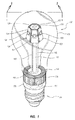
図1および2を参照すると、複数のパネル102と、前記パネル102に取り付けられ、空間照明(即ち、白熱電球を使用して提供されるのと類似した非一方向性の照明)のために中心軸の周りに有利に配置されたLED103とを有するLED照明装置100を示す本発明の一実施形態が図示されている。前記照明装置100からの照明は、前記複数のLED103によって提供される。ガラス製若しくはプラスチック製の電球(または透明なハウジング)106は、前記LED、および組み立てられた前記照明装置100を具現化する種々の構成要素を収容し、当該電球106は従来の電球に類似したサイズとなっている。所望であれば、前記電球は、つや消しされ、着色され、または透明であってもよく、これによって前記照明装置100を従来の光源の外観に類似させることがさらに可能となる。
With reference to FIGS. 1 and 2, a plurality of
一実施形態において、前記パネル102は多面フレーム124に取り付けられている。伝熱管105が上記に参照した中心軸に実質的に沿って延伸し、近位端部120と遠位端部122とを含んでいる。一般的に、前記伝熱管とは、高温から低温に熱を伝導することのできる任意の構造体または材料を指す。前記フレーム124は、前記伝熱管105の近位端部120に固定されている。前記フレーム124は上面部126と下面部128とを有し、これらの面部には、前記伝熱管105の棒状部130に前記フレーム124を取り付けるために、当該面部を通って延伸する穴部132が設けられている。前記フレーム124は、前記パイプ105の外面と前記穴部132の内面との間に強固な摩擦嵌合若しくは熱伝導性ペーストを用いて、又は好適な接着剤若しくは締結具を用いて、前記伝熱管105に固定することができる。
In one embodiment, the
さらに、熱負荷または重量要件によって、前記フレーム124は中実または中空であってよい。比較的軽量の照明装置、例えば前記フレーム124は、例えばアルミニウムまたはその他任意の熱伝導性材料などの薄板金属素材で有利に構成されており、前記シート素材上の折り目を利用して所望の前記3次元多面形状または設計になるように構成されている。一方、比較的重い照明装置に関しては、前記フレームは、前記所望の多面形状または設計に鋳造され、若しくは機械加工され、あるいは別の方法で成形された金属スラグ、またはその他任意の熱伝導性材料を用いて構成することができる。前記中空の設計を採用した実施形態は、前記フレーム124を前記伝熱管105に接続させて前記フレームから前記パイプへの熱伝達を向上させる、例えばロッドまたはフィンなどの熱伝導手段を含んでもよい。前記フレーム124の小面部は、前記照明装置100の所望の光線断面および前記構成要素LEDの発光パターンに応じて、垂直であってもよいし、または、正若しくは負に傾斜してもよい。
Further, the
図1および2にさらに示すように、前記複数のパネル102およびLED103は、前記多面フレーム124の1若しくはそれ以上の面に固定されている。一実施形態において、一対のネジ134により、前記フレーム124の各面に対して、この各面に対応するパネル102が固定されている。各LED103の発光部は前記パネル102の穴部を通って延伸し、一方、前記LEDの裏面は前記パネル102若しくは前記フレームの面のどちらか、またはその両方に、熱伝導性ペースト144を用いて取着されている。一実施形態において、前記LED103は、結線104を用いて各LED103から対応する正および負のリードを接続することによって直列に結線されている。前記LEDはまた、使用される前記構成要素および前記電子駆動部の要件によって、直列および並列回路の組み合わせを用いて接続することもできる。一対の電力伝導用結線140、142が、電子駆動部145から前記LED103に電力を供給する。前記電子駆動部145は、AC入力をLEDの駆動に一般的に必要なDC出力に変換し、前記装置の各種構成要素を相互に電気的に絶縁し、前記LEDの動作を制御(例えば調光を制御)するために使用される。前記電子駆動部145は、前記照明装置100の標準的なエジソンベース111内に配置されており、一般的に導線246、247を介してAC電力を受け取る前記エジソンベースに接続されている。但し、前記フレーム124上のLEDをAC電力によって直接駆動できる場合は、前記電子駆動部145はこの実施形態では必要ない。ネジ山付きベース部は通常、標準的なネジ山付きエジソンベースと関連する構成要素およびサイズを有し、例えば、サイズE27であり、E5〜E40の範囲である。外部電源と接続するうえで、ネジ山付きベース部が一般的に好ましいが、例えばピンまたはプロングのような他の接続手段も本発明の範囲内であるとみなされる。前述の実施形態には表面実装型LEDが一般的に好ましく、当業者であれば、上述の説明は前記LEDの直列結線を参照しているものの、前記LEDはまた並列に結線することも、または直列回路および並列回路の組み合わせを用いて結線することも容易であることを理解するであろう。
As further shown in FIGS. 1 and 2, the plurality of
引き続き図1および2を参照すると、前記伝熱管105の遠位端部122は、ヒートシンク108内に延伸している。前記ヒートシンク108は、熱の放散のためのフィン110を有するように図示されているが、ロッドまたはその他の構成の放熱手段を使用してもよい。前記フィン110は、前記伝熱管105の遠位端部から前記フィン110に向って熱を放出させる伝熱スラグ(slug)112から延出している。一実施形態において、前記ヒートシンク108の下にファンアセンブリ114が位置しており、前記ヒートシンク108のフィン110を通過する冷却用空気の流れを方向づけている。図2に示すように、前記電球106を完全に封止してもよい。このような場合、前記冷却用空気の流れは、前記フィン110および前記電球106の外周面に方向付けられる。あるいは、前記電球106は、前記フィン110に隣接した開口部を含んでもよく、この場合、前記冷却用空気の流れは、前記フィン110を通過し、前記電球106の内部に向かって方向づけられる。ファン114が使用される実施形態を参照すると、前記照明装置100の内部、通常前記ネジ山付きベース部111の上方かつ前記ヒートシンク108の下方に、収容空間116が設けられている。
With continued reference to FIGS. 1 and 2, the
図3を参照すると、一実施形態において、本発明に使用する伝熱管150は、シールされた円筒管152と、吸上げ構造体(wicking structure)154と、前記吸上げ構造内の作動流体152と、前記吸上げ構造体154の内部の中空空間156とを含む。前記伝熱管150の近位端部170に熱が加えられると、その加熱された場所において前記作動流体が気体状態に気化し、気化潜熱を取り込む。この時点でより高い気圧を有する前記気体が、前記中空空間156に沿ってより温度の低い遠位端部172の方向に移動し、そこで液化して液体状態に戻り、前記気化潜熱を前記伝熱管150の遠位端部172に向けて放出する。前記液化した作動流体は、次に前記吸上げ構造体152に沿って前記近位端部170の方向に戻り、この過程が繰り返えされる。
Referring to FIG. 3, in one embodiment, the heat transfer tube 150 used in the present invention includes a sealed
代替の実施形態において、前記伝熱管は、当該伝熱管の作製に使用される材料の融点よりも低い融点を有する内部固体材料を収容する内部区画を含んでもよい。このような場合、前記内部材料の溶融潜熱を利用して、前記内部材料の相が固体から液体に変化するときに、前記LEDによって発生する熱の一部を貯蔵できる。例えば一実施形態において、前記伝熱管はアルミニウムまたは銅で作製されており、どちらも銅およびアルミニウムの双方の融点よりもかなり低い融点を示す、すずまたは鉛を含む内部材料を収容している。また、前記内部材料に好適な金属として、ガリウムを使用してもよい。またさらに別の方法としては、上述のより従来型の伝熱管を、例えばアルミニウムまたは銅のような良好な熱伝導特性を有する材料を使用して作製された中実のロッドに置き換える方法がある。 In an alternative embodiment, the heat transfer tube may include an internal compartment that contains an internal solid material having a melting point that is lower than the melting point of the material used to make the heat transfer tube. In such a case, a part of heat generated by the LED can be stored when the phase of the internal material changes from solid to liquid using the latent heat of fusion of the internal material. For example, in one embodiment, the heat transfer tube is made of aluminum or copper and contains an internal material containing tin or lead, both of which have a melting point much lower than the melting points of both copper and aluminum. Further, gallium may be used as a metal suitable for the internal material. Yet another alternative is to replace the above-described more conventional heat transfer tube with a solid rod made using a material with good thermal conductivity, such as aluminum or copper.
一実施形態において、前記伝熱管は、長さ約2〜約3インチ、直径約1/4〜約3/4インチの円筒状のロッドであり、銅で作製される。前記熱スラグ112を含む前記ヒートシンク108は、直径約1/2〜約1インチで、厚さ約1/4〜約1インチであり、アルミニウムで作製される。前記フレームはアルミニウム製シートで作製された6面からなる6角形状の中空フレームであり、平均直径約1/2〜約1インチ、長さ約1/4〜約1インチ、およびシートの厚さ約1/32〜約1/4インチを有する。前記電球106の形状は、標準的なE27ネジ山付きエジソンベースを有する標準的な100Wの白熱電球の形状に近似している。
In one embodiment, the heat transfer tube is a cylindrical rod having a length of about 2 to about 3 inches and a diameter of about 1/4 to about 3/4 inch, and is made of copper. The
ここで図4を参照すると、本発明の別の実施形態が図示されている。LED照明装置200が、多面フレーム224に取り付けられ、空間照明のために中心軸の周りに有利に配置された複数のLEDチップ203を含んでいる。前記複数のLEDチップ203によって、前記照明装置200からの照明が提供される。本実施形態の照明は、表面実装型LEDではなく多面リードフレーム224上に取り付けられたLEDチップによって提供される点を除けば、この照明構成は図1および2に関して上述したものと同様である。本発明に使用するうえで好適な様々な典型的なチップは、その参照によりその開示が以前に組み込まれている米国特許第6,719,446号明細書(Cao)の中で開示されている。図に示したように、前記LEDチップ203は、前記多面フレーム224に直接取り付けられている。各チップを前記フレーム224に取り付けるために、エポキシなどの好適な接着剤を使用してもよい。ガラス製またはプラスチック製電球206は、前記LEDおよびフレーム224、および以下に詳述する組み立てられた前記照明装置200を具現化する種々の構成要素を収容する。
Referring now to FIG. 4, another embodiment of the present invention is illustrated. An
望ましい場合、1若しくはそれ以上の前記LEDチップ203は、任意選択的な蛍光物質の層250内に収容される。前記蛍光物質の層は、例えば一実施形態において、白色光または白色光の外見を生成するという点において有利である。例えば、このような白色光または白色光の外見は、紫外線LEDチップを使用して白色発光蛍光物質を刺激することにより、または青色LEDチップを使用して黄色発光蛍光物質を刺激し、その黄色光が目の赤および緑受容体を刺激してその結果白色光の外見を提供する赤、緑、および青の混合色を得ることにより生成される。一実施形態において、白色光またはその外見は、セリウムをドープしたイットリウム・アルミニウム・ガーネット結晶からなる帯黄色の蛍光物質の層で覆われた、複数の450〜470nm青色窒化ガリウムLEDチップを使用することによって生成される。
If desired, one or more of the
一実施形態において、前記LEDチップは、第1の結線210を使用して各チップの負の端子を前記フレーム224に接続し、第2の結線214を使用して各チップの正の端子を導電性キャップ212に接続することによって前記照明装置200内で電気的に接続されている。前記導電性キャップ212は、前記フレーム224の頂部に位置しており、エポキシ、AIO、または電気絶縁特性を有するその他任意の材料を用いて作製できる絶縁層216によって、前記フレーム224から電気的に絶縁されている。一対の導電結線240、242が、前記電球装置200の標準的なネジ山付きベース部211から前記LEDチップ203に電力を供給する。前記電力供給結線の対240、242はそれぞれ、前記ベース部211にある対応接触子から内部の電子駆動部245まで延伸している。上述のものと同様に、前記電子駆動部245は、AC入力をLED回路の駆動に一般的に必要なDC出力に変換し、前記装置の各種構成要素を相互に電気的に絶縁し、前記LEDの動作を制御(例えば調光を制御)するために使用される。前記電子駆動部245は、前記照明装置200の標準的なエジソンベース211内に配置されており、一般的に導線246、247を介してAC電力を受け取る前記エジソンベースに接続されている。但し、前記フレーム224上のLEDをAC電力によって直接駆動できる場合は、前記電子駆動部245はこの実施形態では必要ない。その意味では、前記LEDチップ203は並列に結線されている。しかしながら、前述の実施形態を参照して述べたように、この実施形態で開示した結線に対応する直列の結線は、当業者には容易に理解でき、本発明の範囲内であるとみなされる。望ましい場合、エポキシ製のキャップ208が使用され、前記照明装置のその他構成要素のうち、前記フレーム224、第1および第2の
結線210、214、LEDチップ203、および蛍光物質層250が被覆される。前記エポキシ製キャップ208は、光学レンズとして、また前記特定された各種の構成要素の保護層としての役割を果たす。
In one embodiment, the LED chip uses a
引き続き図4を参照すると、前記照明装置200の中心軸に実質的に沿って伝熱管205が延伸し、近位端部220と遠位端部222とを含んでいる。前記フレーム224は、前述の実施形態で上述したものと同様の方法で、前記伝熱管205の近位端部220に固定されている。同様に、前記伝熱管205の遠位端部222は、前述の実施形態で上述したものと同様に構成され、且つ配置されているヒートシンク208内に延伸している。上述の伝熱管およびヒートシンク(それらを冷却する手段を含めて)の各種実施形態は、図1および2を参照して説明した上記の実施形態に等しく適用される。
With continued reference to FIG. 4, the
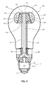
ここで図5および6を参照すると、本発明のさらなる実施形態が開示されている。LED照明装置300が、複数のパネル302と、前記パネル302に取り付けられ、空間照明のために中心軸の周りに有利に配置されたLED303を有している。前記照明装置300からの照明は、前記複数のLED303によって提供される。ガラス製またはプラスチック製の電球306が前記LED、および以下に詳述する、組み立てられた前記照明装置300を具現化する種々の構成要素を収容している。一実施形態において、前記パネル302は、上記に参照した実施形態に関して述べたように構成される多面フレーム324に取り付けられている。より具体的には、この実施形態のフレーム324の形状は電球に近似しており、各面に対して垂直に外側に向かうベクトルが、前記フレームによって形成される近似電球の経度方向および緯度方向の双方に伸び、これにより、よりレベルの高い全方向性空間照明が生成される(即ち、経度方向および緯度方向により多くの面を有するほどよりよい近似物が得られるため、球面方向外向きに発散する光により近くなる)。
With reference now to FIGS. 5 and 6, a further embodiment of the present invention is disclosed. The
前記照明装置300の中心軸に実質的に沿って伝熱管305が延伸し、近位端部320と遠位端部322とを含んでいる。前記フレーム324は、前述の実施形態で上述したものと同様の方法で前記伝熱管305の近位端部320に固定されている。同様に、前記伝熱管305の遠位端部322は、前述の実施形態で上述したものと同様に構成され、且つ配置されているヒートシンク308内に延伸している。上述の伝熱管およびヒートシンク(それらを冷却する手段を含めて)の各種実施形態は、上述の実施形態に等しく適用される。さらに、直列結線または並列結線の方法、蛍光物質またはエポキシによる被覆の任意選択的使用、および冷却ファンの任意選択的使用を含む、表面実装型LEDおよびLEDチップの使用に関する前記各種実施形態は、図5および6に示した実施形態で使用でき、またはそれらの中に組み込むことができることに注目されたい。
A
ここで図7を参照すると、本発明のさらなる実施形態が図示され開示されている。LED照明装置400は、円盤状のフレーム424の形態の第1のヒートシンクと、前記フレーム424に取り付けられ、指向性空間照明のために前記フレームの周りに有利に配置された複数のLED403とを含んでいる。前記照明装置400からの照明は、前記複数のLED403によって提供される。一実施形態において、前記LED403は接続結線404を使用して直列に結線されている。一対の導電線440、442が、前記照明装置400の標準的なネジ山付きベース部411から前記直列結線されたLED403に電力を供給する。前記ベース411内の電子駆動部が前記LEDに電力を提供する。前記フレーム424は、上記に参照した実施形態のフレーム要素に関して説明したように構成でき、即ち、前記フレームは中実または中空であることができる。代替の実施形態において、前記フレーム424は、第1のまたは上面451および第2のまたは下面452と、前記2つの面の間に配置された複数の放熱フィン453とを含んでいる。
Referring now to FIG. 7, a further embodiment of the present invention is shown and disclosed. The LED lighting device 400 includes a first heat sink in the form of a disk-shaped frame 424 and a plurality of
前記照明装置400の中心軸に実質的に沿って伝熱管405が延伸し、近位端部420と遠位端部422とを含んでいる。前記フレーム424は、前述の実施形態で上述したものと同様の方法で前記伝熱管405の近位端部420に固定されている。同様に、前記伝熱管405の遠位端部422は、前述の実施形態で上述したものと同様に構成され、且つ配置されているヒートシンク408内に延伸している。上述の伝熱管およびヒートシンク(それらを冷却する手段を含めて)の各種実施形態は、上述の実施形態に等しく適用される。さらに、直列結線または並列結線の方法、蛍光物質またはエポキシ被覆の任意選択的使用、および冷却ファンの任意選択的使用を含む表面実装型LEDおよびLEDチップの使用に関する各種実施形態の全てを、図7に示した実施形態で使用してもよく、またはそれらに組み込んでもよいことに注目されたい。 A heat transfer tube 405 extends substantially along the central axis of the lighting device 400 and includes a proximal end 420 and a distal end 422. The frame 424 is fixed to the proximal end 420 of the heat transfer tube 405 in the same manner as described above in the previous embodiment. Similarly, the distal end 422 of the heat transfer tube 405 extends into a heat sink 408 that is constructed and arranged similar to that described above in the previous embodiment. The various embodiments of the heat transfer tubes and heat sinks described above (including means for cooling them) apply equally to the embodiments described above. In addition, all of the various embodiments relating to the use of surface mount LEDs and LED chips, including serial or parallel connection methods, optional use of phosphors or epoxy coatings, and optional use of cooling fans are shown in FIG. Note that it may be used in or incorporated into the embodiments shown in FIG.
上述の照明装置を構成するために使用されるLED装置またはLEDチップは、単色若しくは複数色または白色を発光することができる。前記電球または収容カバーはまた、必要に応じてつや消しを施すこともでき、透明であることもでき、または蛍光物質で被覆してLEDからの光を異なる色に変換することもできる。本明細書内および添付の発明開示には、本発明を例示する目的で特定の実施形態および詳細が含まれているが、添付の特許請求の範囲に定義された本発明の範囲から逸脱せずに、本明細書内で開示された方法および装置に様々な変更を施してもよいことは、当業者であれば明らかである。 The LED device or LED chip used to constitute the above-described lighting device can emit single color, multiple colors, or white. The bulb or containment cover can also be frosted as needed, can be transparent, or can be coated with a fluorescent material to convert light from the LED to a different color. The specification and accompanying invention disclosure includes specific embodiments and details for the purpose of illustrating the invention, but without departing from the scope of the invention as defined in the appended claims. In addition, it will be apparent to those skilled in the art that various modifications may be made to the method and apparatus disclosed herein.
Claims (22)
フレームと、
前記フレームに取り付けられた複数のLED光源と、
前記フレームから離間して配置されたヒートシンクと、
前記フレームに接続された近位端部と前記ヒートシンクに接続された遠位端部とを有する伝熱管と、
前記ヒートシンクに近接して配置され、外部電源に接続するように構成された電子駆動部と、
前記電子駆動部を前記複数のLED光源に接続する第1および第2の導電線と
を有する照明装置。 A lighting device,
Frame,
A plurality of LED light sources attached to the frame;
A heat sink disposed away from the frame;
A heat transfer tube having a proximal end connected to the frame and a distal end connected to the heat sink;
An electronic driver disposed in proximity to the heat sink and configured to connect to an external power source;
A lighting device comprising: first and second conductive lines connecting the electronic drive unit to the plurality of LED light sources.
透明なハウジングを有するものである照明装置。 The lighting device according to claim 1, further comprising:
A lighting device having a transparent housing.
複数の面を有する多面伝熱フレームと、
LED光源が前記複数の面の各面に取り付けられた複数のLED光源と、
前記フレームから離間して配置されたヒートシンクと、
前記フレームに接続された近位端部と前記ヒートシンクに接続された遠位端部とを有する伝熱管と、
前記ヒートシンクに近接して配置され、外部電源に接続するように構成された電子駆動部と、
前記電気的接続を前記複数のLED光源および前記電子駆動部に提供する導電体と、
ハウジングと
を有する照明装置。 A lighting device,
A multi-surface heat transfer frame having a plurality of surfaces;
A plurality of LED light sources mounted on each of the plurality of surfaces;
A heat sink disposed away from the frame;
A heat transfer tube having a proximal end connected to the frame and a distal end connected to the heat sink;
An electronic driver disposed in proximity to the heat sink and configured to connect to an external power source;
A conductor providing the electrical connection to the plurality of LED light sources and the electronic driver;
A lighting device having a housing.
複数の面を有する多面伝熱フレームと、
LEDチップ光源が前記複数の面の各面に取り付けられた複数のLEDチップ光源と、
前記フレームから離間して配置され、複数の放熱部材を含み、且つアルミニウムで作製されたヒートシンクと、
前記フレームに接続された近位端部と前記ヒートシンクに接続された遠位端部とを有する伝熱管と、
前記ヒートシンクに近接して配置され、外部電源に接続するように構成されたネジ山付きエジソンベース内に配置された電子駆動部と、
前記電子駆動部を前記複数のLED光源に接続する導電体と、
ハウジングと
を有する照明装置。 A lighting device,
A multi-surface heat transfer frame having a plurality of surfaces;
A plurality of LED chip light sources mounted on each of the plurality of surfaces;
A heat sink disposed apart from the frame, including a plurality of heat dissipating members, and made of aluminum;
A heat transfer tube having a proximal end connected to the frame and a distal end connected to the heat sink;
An electronic driver disposed within a threaded Edison base disposed proximate to the heat sink and configured to connect to an external power source;
A conductor connecting the electronic driving unit to the plurality of LED light sources;
A lighting device having a housing.
フレームと、
前記フレーム上に取り付けられ、AC電源入力を直接受け取るように動作可能な複数のLED光源と、
前記フレームから離間して配置されたヒートシンクと、
前記フレームに接続された近位端部と前記ヒートシンクに接続された遠位端部とを有する伝熱管と、
前記ヒートシンクに近接して配置され、外部電源に接続するように構成された接続ベースと、
前記接続ベースを前記複数のLED光源に接続する第1および第2の導電線と
を有する照明装置。 A lighting device,
Frame,
A plurality of LED light sources mounted on the frame and operable to directly receive an AC power input;
A heat sink disposed away from the frame;
A heat transfer tube having a proximal end connected to the frame and a distal end connected to the heat sink;
A connection base disposed proximate to the heat sink and configured to connect to an external power source;
A lighting device comprising: first and second conductive lines connecting the connection base to the plurality of LED light sources.
Applications Claiming Priority (3)
| Application Number | Priority Date | Filing Date | Title |
|---|---|---|---|
| US20775109P | 2009-02-17 | 2009-02-17 | |
| US61/207,751 | 2009-02-17 | ||
| PCT/US2010/024489 WO2010096498A1 (en) | 2009-02-17 | 2010-02-17 | Led light bulbs for space lighting |
Publications (2)
| Publication Number | Publication Date |
|---|---|
| JP2012518254A true JP2012518254A (en) | 2012-08-09 |
| JP2012518254A5 JP2012518254A5 (en) | 2013-04-04 |
Family
ID=42559270
Family Applications (1)
| Application Number | Title | Priority Date | Filing Date |
|---|---|---|---|
| JP2011550324A Pending JP2012518254A (en) | 2009-02-17 | 2010-02-17 | LED bulbs for space lighting |
Country Status (6)
| Country | Link |
|---|---|
| US (1) | US8653723B2 (en) |
| EP (2) | EP3273161A1 (en) |
| JP (1) | JP2012518254A (en) |
| KR (1) | KR20110117090A (en) |
| CN (1) | CN102301181A (en) |
| WO (1) | WO2010096498A1 (en) |
Cited By (3)
| Publication number | Priority date | Publication date | Assignee | Title |
|---|---|---|---|---|
| JP2014146510A (en) * | 2013-01-29 | 2014-08-14 | Panasonic Corp | Light source for lighting and lighting device |
| TWI512232B (en) * | 2012-12-04 | 2015-12-11 | Advanced Optoelectronic Tech | Light emitting diode bulb |
| JP2017174828A (en) * | 2017-06-16 | 2017-09-28 | Necライティング株式会社 | Lighting device, heat sink and light-emitting element substrate |
Families Citing this family (198)
| Publication number | Priority date | Publication date | Assignee | Title |
|---|---|---|---|---|
| US6200134B1 (en) | 1998-01-20 | 2001-03-13 | Kerr Corporation | Apparatus and method for curing materials with radiation |
| US7728345B2 (en) | 2001-08-24 | 2010-06-01 | Cao Group, Inc. | Semiconductor light source for illuminating a physical space including a 3-dimensional lead frame |
| US7182597B2 (en) | 2002-08-08 | 2007-02-27 | Kerr Corporation | Curing light instrument |
| US10340424B2 (en) | 2002-08-30 | 2019-07-02 | GE Lighting Solutions, LLC | Light emitting diode component |
| US8113830B2 (en) | 2005-05-27 | 2012-02-14 | Kerr Corporation | Curing light instrument |
| US9412926B2 (en) | 2005-06-10 | 2016-08-09 | Cree, Inc. | High power solid-state lamp |
| US9066777B2 (en) | 2009-04-02 | 2015-06-30 | Kerr Corporation | Curing light device |
| US9072572B2 (en) | 2009-04-02 | 2015-07-07 | Kerr Corporation | Dental light device |
| US8791499B1 (en) | 2009-05-27 | 2014-07-29 | Soraa, Inc. | GaN containing optical devices and method with ESD stability |
| US20100301728A1 (en) * | 2009-06-02 | 2010-12-02 | Bridgelux, Inc. | Light source having a refractive element |
| US8922106B2 (en) * | 2009-06-02 | 2014-12-30 | Bridgelux, Inc. | Light source with optics to produce a spherical emission pattern |
| US8186852B2 (en) * | 2009-06-24 | 2012-05-29 | Elumigen Llc | Opto-thermal solution for multi-utility solid state lighting device using conic section geometries |
| CN102597618A (en) * | 2009-09-10 | 2012-07-18 | 哈米什·麦克伦南 | Improved light emitting diode (led) assembly and method of manufacturing the same |
| US8678618B2 (en) * | 2009-09-25 | 2014-03-25 | Toshiba Lighting & Technology Corporation | Self-ballasted lamp having a light-transmissive member in contact with light emitting elements and lighting equipment incorporating the same |
| US8593040B2 (en) | 2009-10-02 | 2013-11-26 | Ge Lighting Solutions Llc | LED lamp with surface area enhancing fins |
| US9243758B2 (en) | 2009-10-20 | 2016-01-26 | Cree, Inc. | Compact heat sinks and solid state lamp incorporating same |
| US9217542B2 (en) | 2009-10-20 | 2015-12-22 | Cree, Inc. | Heat sinks and lamp incorporating same |
| WO2011094901A1 (en) * | 2010-02-08 | 2011-08-11 | Chen Jenshyan | Led light source |
| US9316361B2 (en) | 2010-03-03 | 2016-04-19 | Cree, Inc. | LED lamp with remote phosphor and diffuser configuration |
| US8931933B2 (en) * | 2010-03-03 | 2015-01-13 | Cree, Inc. | LED lamp with active cooling element |
| US8882284B2 (en) | 2010-03-03 | 2014-11-11 | Cree, Inc. | LED lamp or bulb with remote phosphor and diffuser configuration with enhanced scattering properties |
| US9625105B2 (en) * | 2010-03-03 | 2017-04-18 | Cree, Inc. | LED lamp with active cooling element |
| US8632196B2 (en) * | 2010-03-03 | 2014-01-21 | Cree, Inc. | LED lamp incorporating remote phosphor and diffuser with heat dissipation features |
| US20110227102A1 (en) * | 2010-03-03 | 2011-09-22 | Cree, Inc. | High efficacy led lamp with remote phosphor and diffuser configuration |
| US9275979B2 (en) * | 2010-03-03 | 2016-03-01 | Cree, Inc. | Enhanced color rendering index emitter through phosphor separation |
| US9062830B2 (en) | 2010-03-03 | 2015-06-23 | Cree, Inc. | High efficiency solid state lamp and bulb |
| US9310030B2 (en) | 2010-03-03 | 2016-04-12 | Cree, Inc. | Non-uniform diffuser to scatter light into uniform emission pattern |
| US9500325B2 (en) * | 2010-03-03 | 2016-11-22 | Cree, Inc. | LED lamp incorporating remote phosphor with heat dissipation features |
| US9057511B2 (en) | 2010-03-03 | 2015-06-16 | Cree, Inc. | High efficiency solid state lamp and bulb |
| US9024517B2 (en) * | 2010-03-03 | 2015-05-05 | Cree, Inc. | LED lamp with remote phosphor and diffuser configuration utilizing red emitters |
| US10359151B2 (en) | 2010-03-03 | 2019-07-23 | Ideal Industries Lighting Llc | Solid state lamp with thermal spreading elements and light directing optics |
| US9052067B2 (en) | 2010-12-22 | 2015-06-09 | Cree, Inc. | LED lamp with high color rendering index |
| US8562161B2 (en) | 2010-03-03 | 2013-10-22 | Cree, Inc. | LED based pedestal-type lighting structure |
| US9157602B2 (en) | 2010-05-10 | 2015-10-13 | Cree, Inc. | Optical element for a light source and lighting system using same |
| US20110278633A1 (en) * | 2010-05-11 | 2011-11-17 | Scott Allen Clifford | LED Light Bulb With Integrated Heat Sink |
| US9599322B2 (en) * | 2010-05-11 | 2017-03-21 | Polybrite International, Inc. | High intensity LED replacement of incandescent lamps |
| JP4717148B1 (en) * | 2010-05-28 | 2011-07-06 | 株式会社スズデン | Lighting apparatus and method of manufacturing the lighting apparatus |
| US8227961B2 (en) | 2010-06-04 | 2012-07-24 | Cree, Inc. | Lighting device with reverse tapered heatsink |
| US8596821B2 (en) | 2010-06-08 | 2013-12-03 | Cree, Inc. | LED light bulbs |
| CN201696936U (en) * | 2010-06-13 | 2011-01-05 | 沈锦祥 | LED tower-shaped luminescent module |
| US10451251B2 (en) | 2010-08-02 | 2019-10-22 | Ideal Industries Lighting, LLC | Solid state lamp with light directing optics and diffuser |
| ES2531050T5 (en) * | 2010-09-08 | 2021-05-04 | Zhejiang Ledison Optoelectronics Co Ltd | LED bulb and LED light bar capable of emitting light above 4 PI |
| CN102401359A (en) * | 2010-09-15 | 2012-04-04 | 奇鋐科技股份有限公司 | Light emitting diode (LED) bulb radiating structure |
| US8272762B2 (en) * | 2010-09-28 | 2012-09-25 | Lighting Science Group Corporation | LED luminaire |
| US9279543B2 (en) | 2010-10-08 | 2016-03-08 | Cree, Inc. | LED package mount |
| US8803452B2 (en) | 2010-10-08 | 2014-08-12 | Soraa, Inc. | High intensity light source |
| CN102454966A (en) * | 2010-10-22 | 2012-05-16 | 富准精密工业(深圳)有限公司 | Heat radiation device and LED lamp applying same |
| TWM412319U (en) * | 2010-11-01 | 2011-09-21 | Parlux Optoelectronics Corp | LED illumination device |
| US9016900B2 (en) * | 2010-11-04 | 2015-04-28 | Panasonic Intellectual Property Management Co., Ltd. | Light bulb shaped lamp and lighting apparatus |
| JP5511977B2 (en) | 2010-11-04 | 2014-06-04 | パナソニック株式会社 | Light bulb shaped lamp and lighting device |
| TWI422776B (en) * | 2010-12-15 | 2014-01-11 | Cal Comp Electronics & Comm Co | Lighting apparatus |
| WO2012098600A1 (en) * | 2011-01-18 | 2012-07-26 | パナソニック株式会社 | Light bulb-type lamp and illumination device |
| JP5691542B2 (en) | 2011-01-18 | 2015-04-01 | トヨタ紡織株式会社 | Vehicle seat slide device |
| US9234655B2 (en) * | 2011-02-07 | 2016-01-12 | Cree, Inc. | Lamp with remote LED light source and heat dissipating elements |
| US9068701B2 (en) * | 2012-01-26 | 2015-06-30 | Cree, Inc. | Lamp structure with remote LED light source |
| US8829774B1 (en) | 2011-02-11 | 2014-09-09 | Soraa, Inc. | Illumination source with direct die placement |
| US10036544B1 (en) | 2011-02-11 | 2018-07-31 | Soraa, Inc. | Illumination source with reduced weight |
| US11251164B2 (en) | 2011-02-16 | 2022-02-15 | Creeled, Inc. | Multi-layer conversion material for down conversion in solid state lighting |
| US20120224371A1 (en) * | 2011-03-02 | 2012-09-06 | Kinpo Electronics, Inc. | Lighting apparatus |
| CN103597592B (en) * | 2011-03-17 | 2016-10-05 | 北京优格莱照明科技有限公司 | Liquid-cooling LED illuminating lamp |
| US8272766B2 (en) * | 2011-03-18 | 2012-09-25 | Abl Ip Holding Llc | Semiconductor lamp with thermal handling system |
| US8461752B2 (en) * | 2011-03-18 | 2013-06-11 | Abl Ip Holding Llc | White light lamp using semiconductor light emitter(s) and remotely deployed phosphor(s) |
| US8803412B2 (en) | 2011-03-18 | 2014-08-12 | Abl Ip Holding Llc | Semiconductor lamp |
| DE102011007221B4 (en) * | 2011-04-12 | 2022-05-19 | Ledvance Gmbh | lighting device |
| US10030863B2 (en) * | 2011-04-19 | 2018-07-24 | Cree, Inc. | Heat sink structures, lighting elements and lamps incorporating same, and methods of making same |
| US9470882B2 (en) | 2011-04-25 | 2016-10-18 | Cree, Inc. | Optical arrangement for a solid-state lamp |
| US10094548B2 (en) | 2011-05-09 | 2018-10-09 | Cree, Inc. | High efficiency LED lamp |
| US9797589B2 (en) | 2011-05-09 | 2017-10-24 | Cree, Inc. | High efficiency LED lamp |
| US9360202B2 (en) * | 2011-05-13 | 2016-06-07 | Lighting Science Group Corporation | System for actively cooling an LED filament and associated methods |
| US8414160B2 (en) * | 2011-06-13 | 2013-04-09 | Tsmc Solid State Lighting Ltd. | LED lamp and method of making the same |
| CN203771077U (en) * | 2011-07-22 | 2014-08-13 | 松下电器产业株式会社 | Lamp |
| US8746915B2 (en) * | 2011-07-29 | 2014-06-10 | Cree, Inc. | Light emitting die (LED) lamps, heat sinks and related methods |
| CN202140877U (en) * | 2011-08-02 | 2012-02-08 | 惠州市东扬科技有限公司 | SMD LED lamp bulb |
| USD736723S1 (en) | 2011-08-15 | 2015-08-18 | Soraa, Inc. | LED lamp |
| USD736724S1 (en) | 2011-08-15 | 2015-08-18 | Soraa, Inc. | LED lamp with accessory |
| KR101326518B1 (en) | 2011-09-02 | 2013-11-07 | 엘지이노텍 주식회사 | Lighting device |
| US9488324B2 (en) | 2011-09-02 | 2016-11-08 | Soraa, Inc. | Accessories for LED lamp systems |
| US9109760B2 (en) | 2011-09-02 | 2015-08-18 | Soraa, Inc. | Accessories for LED lamps |
| WO2013042662A1 (en) | 2011-09-20 | 2013-03-28 | シチズンホールディングス株式会社 | Led module and led lamp employing same |
| US8884517B1 (en) | 2011-10-17 | 2014-11-11 | Soraa, Inc. | Illumination sources with thermally-isolated electronics |
| CN108317407A (en) * | 2011-10-31 | 2018-07-24 | 晶元光电股份有限公司 | Led light source |
| KR101318432B1 (en) * | 2011-11-14 | 2013-10-16 | 아이스파이프 주식회사 | Led lighting apparatus |
| JP2013105711A (en) * | 2011-11-16 | 2013-05-30 | Toshiba Lighting & Technology Corp | Luminaire |
| KR20130058350A (en) * | 2011-11-25 | 2013-06-04 | 삼성전자주식회사 | Light emitting diode for automobile lamp |
| US9482421B2 (en) | 2011-12-30 | 2016-11-01 | Cree, Inc. | Lamp with LED array and thermal coupling medium |
| KR102017538B1 (en) | 2012-01-31 | 2019-10-21 | 엘지이노텍 주식회사 | Lighting device |
| TWI491830B (en) * | 2012-02-14 | 2015-07-11 | Av Tech Corp | Illuminating device with variable light beam and assemble method thereof |
| US20150023014A1 (en) * | 2012-02-16 | 2015-01-22 | Panasonic Corporation | Lamp and lighting apparatus |
| US9194556B1 (en) * | 2012-02-22 | 2015-11-24 | Theodore G. Nelson | Method of producing LED lighting apparatus and apparatus produced thereby |
| US9228728B2 (en) * | 2012-02-23 | 2016-01-05 | Koninklijke Philips N.V. | Luminaire module |
| US9488359B2 (en) * | 2012-03-26 | 2016-11-08 | Cree, Inc. | Passive phase change radiators for LED lamps and fixtures |
| US9022601B2 (en) | 2012-04-09 | 2015-05-05 | Cree, Inc. | Optical element including texturing to control beam width and color mixing |
| US9651240B2 (en) * | 2013-11-14 | 2017-05-16 | Cree, Inc. | LED lamp |
| US9310065B2 (en) | 2012-04-13 | 2016-04-12 | Cree, Inc. | Gas cooled LED lamp |
| US9322543B2 (en) | 2012-04-13 | 2016-04-26 | Cree, Inc. | Gas cooled LED lamp with heat conductive submount |
| US9234638B2 (en) | 2012-04-13 | 2016-01-12 | Cree, Inc. | LED lamp with thermally conductive enclosure |
| US9395051B2 (en) | 2012-04-13 | 2016-07-19 | Cree, Inc. | Gas cooled LED lamp |
| US9395074B2 (en) | 2012-04-13 | 2016-07-19 | Cree, Inc. | LED lamp with LED assembly on a heat sink tower |
| US9951909B2 (en) | 2012-04-13 | 2018-04-24 | Cree, Inc. | LED lamp |
| US9410687B2 (en) | 2012-04-13 | 2016-08-09 | Cree, Inc. | LED lamp with filament style LED assembly |
| US9310028B2 (en) | 2012-04-13 | 2016-04-12 | Cree, Inc. | LED lamp with LEDs having a longitudinally directed emission profile |
| US8757839B2 (en) | 2012-04-13 | 2014-06-24 | Cree, Inc. | Gas cooled LED lamp |
| US8985794B1 (en) | 2012-04-17 | 2015-03-24 | Soraa, Inc. | Providing remote blue phosphors in an LED lamp |
| US9500355B2 (en) | 2012-05-04 | 2016-11-22 | GE Lighting Solutions, LLC | Lamp with light emitting elements surrounding active cooling device |
| US8680755B2 (en) | 2012-05-07 | 2014-03-25 | Lg Innotek Co., Ltd. | Lighting device having reflectors for indirect light emission |
| US9360190B1 (en) | 2012-05-14 | 2016-06-07 | Soraa, Inc. | Compact lens for high intensity light source |
| US9310052B1 (en) | 2012-09-28 | 2016-04-12 | Soraa, Inc. | Compact lens for high intensity light source |
| US10436422B1 (en) | 2012-05-14 | 2019-10-08 | Soraa, Inc. | Multi-function active accessories for LED lamps |
| US9995439B1 (en) | 2012-05-14 | 2018-06-12 | Soraa, Inc. | Glare reduced compact lens for high intensity light source |
| EP2856023B1 (en) * | 2012-05-29 | 2018-04-25 | Philips Lighting Holding B.V. | Lighting device having a light source heat sink arranged separate from a driver |
| WO2013182973A1 (en) | 2012-06-04 | 2013-12-12 | Koninklijke Philips N.V. | Led lamp unit, in particular for automotive lamps |
| US10362679B2 (en) * | 2012-06-04 | 2019-07-23 | Signify Holding B.V. | Lamp comprising a flexible printed circuit board |
| CN102748622A (en) * | 2012-06-25 | 2012-10-24 | 歌尔声学股份有限公司 | LED (Light-Emitting Diode) bulb lamp |
| WO2014015484A1 (en) * | 2012-07-25 | 2014-01-30 | 深圳市益科光电技术有限公司 | Led automobile headlamp |
| US9097393B2 (en) | 2012-08-31 | 2015-08-04 | Cree, Inc. | LED based lamp assembly |
| US9097396B2 (en) | 2012-09-04 | 2015-08-04 | Cree, Inc. | LED based lighting system |
| US20140098528A1 (en) * | 2012-10-04 | 2014-04-10 | Tadd, LLC | Led retrofit lamp |
| US20140098568A1 (en) * | 2012-10-04 | 2014-04-10 | Tadd, LLC | Led retrofit lamp |
| US9134006B2 (en) | 2012-10-22 | 2015-09-15 | Cree, Inc. | Beam shaping lens and LED lighting system using same |
| KR20140056826A (en) | 2012-11-01 | 2014-05-12 | 삼성전자주식회사 | Light emitting device |
| CN102927476B (en) * | 2012-11-08 | 2014-08-20 | 浙江阳光照明电器集团股份有限公司 | Light emitting diode (LED) spherical lamp transmitting heat through liquid |
| US9215764B1 (en) | 2012-11-09 | 2015-12-15 | Soraa, Inc. | High-temperature ultra-low ripple multi-stage LED driver and LED control circuits |
| US9062863B2 (en) | 2012-12-10 | 2015-06-23 | Avago Technologies General Ip (Singapore) Pte. Ltd. | System, device, and method for adjusting color output through active cooling mechanism |
| CN102980163B (en) * | 2012-12-20 | 2015-07-22 | 纳晶科技股份有限公司 | Heat conduction connector for lamp and lamp including same |
| CN103047569B (en) * | 2012-12-20 | 2015-10-28 | 华南理工大学 | A kind of LED lamp bulb structure |
| US9570661B2 (en) | 2013-01-10 | 2017-02-14 | Cree, Inc. | Protective coating for LED lamp |
| US9303857B2 (en) | 2013-02-04 | 2016-04-05 | Cree, Inc. | LED lamp with omnidirectional light distribution |
| US9267661B1 (en) | 2013-03-01 | 2016-02-23 | Soraa, Inc. | Apportioning optical projection paths in an LED lamp |
| US9435525B1 (en) | 2013-03-08 | 2016-09-06 | Soraa, Inc. | Multi-part heat exchanger for LED lamps |
| US9664369B2 (en) | 2013-03-13 | 2017-05-30 | Cree, Inc. | LED lamp |
| US9052093B2 (en) | 2013-03-14 | 2015-06-09 | Cree, Inc. | LED lamp and heat sink |
| US9115870B2 (en) | 2013-03-14 | 2015-08-25 | Cree, Inc. | LED lamp and hybrid reflector |
| US8899794B2 (en) | 2013-03-15 | 2014-12-02 | Bby Solutions, Inc. | LED bulb optical system with uniform light distribution |
| US9243777B2 (en) | 2013-03-15 | 2016-01-26 | Cree, Inc. | Rare earth optical elements for LED lamp |
| US9657922B2 (en) | 2013-03-15 | 2017-05-23 | Cree, Inc. | Electrically insulative coatings for LED lamp and elements |
| US9435492B2 (en) | 2013-03-15 | 2016-09-06 | Cree, Inc. | LED luminaire with improved thermal management and novel LED interconnecting architecture |
| US9285082B2 (en) | 2013-03-28 | 2016-03-15 | Cree, Inc. | LED lamp with LED board heat sink |
| US8894252B2 (en) * | 2013-04-19 | 2014-11-25 | Technical Consumer Products, Inc. | Filament LED lamp |
| US10094523B2 (en) | 2013-04-19 | 2018-10-09 | Cree, Inc. | LED assembly |
| US9310031B2 (en) | 2013-06-06 | 2016-04-12 | Interlight Optotech Corporation | Light emitting diode bulb |
| TWI626395B (en) | 2013-06-11 | 2018-06-11 | 晶元光電股份有限公司 | Light emitting device |
| PL224281B1 (en) | 2013-08-05 | 2016-12-30 | Skrobotowicz Piotr Auto Power Electronic | Light bulb with LEDs |
| CN103471063A (en) * | 2013-09-23 | 2013-12-25 | 立达信绿色照明股份有限公司 | High heat-dissipating bulb |
| JP5617982B2 (en) * | 2013-09-25 | 2014-11-05 | 東芝ライテック株式会社 | Lamp with lamp and lighting equipment |
| US9541241B2 (en) | 2013-10-03 | 2017-01-10 | Cree, Inc. | LED lamp |
| CN203641941U (en) * | 2013-10-31 | 2014-06-11 | 陈清辉 | LED bulb |
| CN103574368B (en) * | 2013-11-12 | 2015-11-04 | 无锡天地合同能源管理有限公司 | LEDbulb lamp |
| CN104676289A (en) * | 2013-11-26 | 2015-06-03 | 苏州承源光电科技有限公司 | LED lighting lamp |
| TWI553266B (en) * | 2014-01-13 | 2016-10-11 | 國立臺灣科技大學 | Liquid cooled led light emitting device |
| US10030819B2 (en) | 2014-01-30 | 2018-07-24 | Cree, Inc. | LED lamp and heat sink |
| US9464802B2 (en) * | 2014-02-19 | 2016-10-11 | Ozyegin Universitesi | Flow controlled effective LED based lighting system |
| US9360188B2 (en) | 2014-02-20 | 2016-06-07 | Cree, Inc. | Remote phosphor element filled with transparent material and method for forming multisection optical elements |
| US9518704B2 (en) | 2014-02-25 | 2016-12-13 | Cree, Inc. | LED lamp with an interior electrical connection |
| US9759387B2 (en) | 2014-03-04 | 2017-09-12 | Cree, Inc. | Dual optical interface LED lamp |
| US9462651B2 (en) | 2014-03-24 | 2016-10-04 | Cree, Inc. | Three-way solid-state light bulb |
| US9562677B2 (en) | 2014-04-09 | 2017-02-07 | Cree, Inc. | LED lamp having at least two sectors |
| US9435528B2 (en) | 2014-04-16 | 2016-09-06 | Cree, Inc. | LED lamp with LED assembly retention member |
| US9488322B2 (en) | 2014-04-23 | 2016-11-08 | Cree, Inc. | LED lamp with LED board heat sink |
| US9618162B2 (en) | 2014-04-25 | 2017-04-11 | Cree, Inc. | LED lamp |
| US9951910B2 (en) | 2014-05-19 | 2018-04-24 | Cree, Inc. | LED lamp with base having a biased electrical interconnect |
| CN103982822A (en) * | 2014-05-28 | 2014-08-13 | 昆山生态屋建筑技术有限公司 | Reflector lamp with fan arranged on heat conduction pillar |
| US9618163B2 (en) | 2014-06-17 | 2017-04-11 | Cree, Inc. | LED lamp with electronics board to submount connection |
| TW201600790A (en) * | 2014-06-27 | 2016-01-01 | Formosa Optronics Co Ltd | Omnidirectional lamp |
| US9488767B2 (en) | 2014-08-05 | 2016-11-08 | Cree, Inc. | LED based lighting system |
| CN204141334U (en) * | 2014-10-10 | 2015-02-04 | 佛山燊业光电有限公司 | A kind of comprehensive LEDbulb lamp without blackening |
| CN104406070B (en) * | 2014-11-19 | 2017-01-11 | 广州荣基能亮节能科技有限公司 | Three-dimensional luminous LED (Light Emitting Diode) bulb lamp and preparation method thereof |
| KR101702186B1 (en) * | 2014-11-28 | 2017-02-13 | 백두산 | Lighting device |
| US9401468B2 (en) | 2014-12-24 | 2016-07-26 | GE Lighting Solutions, LLC | Lamp with LED chips cooled by a phase transformation loop |
| USD755414S1 (en) | 2015-02-12 | 2016-05-03 | Tadd, LLC | LED lamp |
| USD755415S1 (en) | 2015-03-03 | 2016-05-03 | Tadd, LLC | LED lamp |
| US10172215B2 (en) | 2015-03-13 | 2019-01-01 | Cree, Inc. | LED lamp with refracting optic element |
| US9702512B2 (en) | 2015-03-13 | 2017-07-11 | Cree, Inc. | Solid-state lamp with angular distribution optic |
| US9909723B2 (en) | 2015-07-30 | 2018-03-06 | Cree, Inc. | Small form-factor LED lamp with color-controlled dimming |
| US9551464B2 (en) * | 2015-03-23 | 2017-01-24 | Uniled Lighting Taiwan Inc. | Low profile LED lamp bulb |
| US10302278B2 (en) | 2015-04-09 | 2019-05-28 | Cree, Inc. | LED bulb with back-reflecting optic |
| USD777354S1 (en) | 2015-05-26 | 2017-01-24 | Cree, Inc. | LED light bulb |
| US9890940B2 (en) | 2015-05-29 | 2018-02-13 | Cree, Inc. | LED board with peripheral thermal contact |
| KR101603576B1 (en) * | 2015-06-03 | 2016-03-16 | 홍중곤 | air circulation type LED electric bulb assembly |
| US10082269B2 (en) * | 2015-06-08 | 2018-09-25 | Cree, Inc. | LED lamp |
| CN106439531A (en) * | 2015-08-07 | 2017-02-22 | 深圳市裕富照明有限公司 | Air inflation LED bulb |
| WO2017034366A1 (en) * | 2015-08-27 | 2017-03-02 | 주식회사 필룩스 | Electric bulb |
| US20170122498A1 (en) * | 2015-10-30 | 2017-05-04 | General Electric Company | Lamp design with led stem structure |
| JP6692417B2 (en) * | 2016-05-10 | 2020-05-13 | 三菱電機株式会社 | heatsink |
| WO2018034628A1 (en) * | 2016-08-19 | 2018-02-22 | Ozyegin Universitesi | Flow cooled solid state lighting with preferred optical and advanced sensing features |
| CN106402681A (en) * | 2016-10-17 | 2017-02-15 | 漳州立达信光电子科技有限公司 | LED (Light-emitting diode) lighting device |
| US10578510B2 (en) * | 2016-11-28 | 2020-03-03 | Applied Materials, Inc. | Device for desorbing molecules from chamber walls |
| CN110050157A (en) | 2016-12-09 | 2019-07-23 | 昕诺飞控股有限公司 | Lighting module and lamps and lanterns including lighting module |
| US10330263B2 (en) * | 2017-02-26 | 2019-06-25 | Leedarson America Inc. | Light apparatus |
| US10738946B2 (en) * | 2017-02-26 | 2020-08-11 | Xiamen Eco Lighting Co., Ltd. | LED light bulb |
| US10260683B2 (en) | 2017-05-10 | 2019-04-16 | Cree, Inc. | Solid-state lamp with LED filaments having different CCT's |
| US10605447B2 (en) * | 2018-04-24 | 2020-03-31 | Xiamen Eco Lighting Co. Ltd. | LED filament bulb apparatus |
| US10816145B2 (en) * | 2018-09-19 | 2020-10-27 | Ledvance Llc | Light emitting diode filament light source |
| US11408602B2 (en) | 2018-10-10 | 2022-08-09 | Elumigen, Llc | High intensity discharge light assembly |
| US11092325B2 (en) * | 2018-10-10 | 2021-08-17 | Elumigen, Llc | High intensity discharge light assembly |
| CN210267016U (en) * | 2019-07-03 | 2020-04-07 | 极光国际有限公司 | LED candle lamp |
| CN114341545A (en) * | 2019-07-08 | 2022-04-12 | 亮锐控股有限公司 | Support for light emitting elements and lighting devices |
| KR102099966B1 (en) * | 2019-08-28 | 2020-04-13 | 주식회사 한승 | LED Bulb with Reflector |
| WO2021225804A1 (en) * | 2020-05-07 | 2021-11-11 | Lumileds Llc | Lighting device comprising support structure with improved thermal and optical properties |
Citations (1)
| Publication number | Priority date | Publication date | Assignee | Title |
|---|---|---|---|---|
| JP2004296245A (en) * | 2003-03-26 | 2004-10-21 | Matsushita Electric Works Ltd | Led lamp |
Family Cites Families (107)
| Publication number | Priority date | Publication date | Assignee | Title |
|---|---|---|---|---|
| US1151377A (en) * | 1915-03-24 | 1915-08-24 | Arthur Douglas Nash | Light unit. |
| US4240090A (en) * | 1978-06-14 | 1980-12-16 | Rca Corporation | Electroluminescent semiconductor device with fiber-optic face plate |
| US4394679A (en) * | 1980-09-15 | 1983-07-19 | Rca Corporation | Light emitting device with a continuous layer of copper covering the entire header |
| US4675575A (en) * | 1984-07-13 | 1987-06-23 | E & G Enterprises | Light-emitting diode assemblies and systems therefore |
| JPH0416447Y2 (en) * | 1985-07-22 | 1992-04-13 | ||
| US4674011A (en) * | 1986-09-10 | 1987-06-16 | The United States Of America As Represented By The Secretary Of The Air Force | Alignment reference device |
| US5055892A (en) * | 1989-08-29 | 1991-10-08 | Hewlett-Packard Company | High efficiency lamp or light accepter |
| US5204871A (en) * | 1990-03-29 | 1993-04-20 | Larkins Eric C | Bistable optical laser based on a heterostructure pnpn thyristor |
| US5174646A (en) * | 1990-12-06 | 1992-12-29 | The Regents Of The University Of California | Heat transfer assembly for a fluorescent lamp and fixture |
| US5160200A (en) * | 1991-03-06 | 1992-11-03 | R & D Molded Products, Inc. | Wedge-base LED bulb housing |
| GB2270199B (en) * | 1992-08-25 | 1995-05-10 | Mitsubishi Cable Ind Ltd | Semiconductor light emitting element |
| US5655830A (en) * | 1993-12-01 | 1997-08-12 | General Signal Corporation | Lighting device |
| US5463280A (en) * | 1994-03-03 | 1995-10-31 | National Service Industries, Inc. | Light emitting diode retrofit lamp |
| JP2596709B2 (en) * | 1994-04-06 | 1997-04-02 | 都築 省吾 | Illumination light source device using semiconductor laser element |
| US5595438A (en) * | 1995-03-16 | 1997-01-21 | Burd David M | Reflective hybrid lamp assembly |
| US5721430A (en) * | 1995-04-13 | 1998-02-24 | Engelhard Sensor Technologies Inc. | Passive and active infrared analysis gas sensors and applicable multichannel detector assembles |
| US5575459A (en) * | 1995-04-27 | 1996-11-19 | Uniglo Canada Inc. | Light emitting diode lamp |
| US5765940A (en) * | 1995-10-31 | 1998-06-16 | Dialight Corporation | LED-illuminated stop/tail lamp assembly |
| US5707139A (en) * | 1995-11-01 | 1998-01-13 | Hewlett-Packard Company | Vertical cavity surface emitting laser arrays for illumination |
| US5688042A (en) * | 1995-11-17 | 1997-11-18 | Lumacell, Inc. | LED lamp |
| US6238077B1 (en) * | 1996-01-23 | 2001-05-29 | Advanced Optical Technologies, L.L.C. | Apparatus for projecting electromagnetic radiation with a tailored intensity distribution |
| US5806965A (en) * | 1996-01-30 | 1998-09-15 | R&M Deese, Inc. | LED beacon light |
| US5890794A (en) * | 1996-04-03 | 1999-04-06 | Abtahi; Homayoon | Lighting units |
| JP2909023B2 (en) * | 1996-05-01 | 1999-06-23 | 日吉電子株式会社 | Long light emitting device |
| US5803579A (en) * | 1996-06-13 | 1998-09-08 | Gentex Corporation | Illuminator assembly incorporating light emitting diodes |
| US6045240A (en) * | 1996-06-27 | 2000-04-04 | Relume Corporation | LED lamp assembly with means to conduct heat away from the LEDS |
| US5813752A (en) * | 1997-05-27 | 1998-09-29 | Philips Electronics North America Corporation | UV/blue LED-phosphor device with short wave pass, long wave pass band pass and peroit filters |
| US6015979A (en) * | 1997-08-29 | 2000-01-18 | Kabushiki Kaisha Toshiba | Nitride-based semiconductor element and method for manufacturing the same |
| US5947588A (en) * | 1997-10-06 | 1999-09-07 | Grand General Accessories Manufacturing Inc. | Light fixture with an LED light bulb having a conventional connection post |
| US5982092A (en) * | 1997-10-06 | 1999-11-09 | Chen; Hsing | Light Emitting Diode planar light source with blue light or ultraviolet ray-emitting luminescent crystal with optional UV filter |
| US6412971B1 (en) * | 1998-01-02 | 2002-07-02 | General Electric Company | Light source including an array of light emitting semiconductor devices and control method |
| US6504180B1 (en) * | 1998-07-28 | 2003-01-07 | Imec Vzw And Vrije Universiteit | Method of manufacturing surface textured high-efficiency radiating devices and devices obtained therefrom |
| DE29817609U1 (en) * | 1998-09-02 | 2000-01-13 | Derksen Gabriele | Illuminant |
| ES2289822T3 (en) * | 1998-09-17 | 2008-02-01 | Koninklijke Philips Electronics N.V. | LED LAMP. |
| US5941631A (en) * | 1998-10-29 | 1999-08-24 | Bright Yin Huey Co., Ltd. | Pendent lamp structure |
| US6149283A (en) * | 1998-12-09 | 2000-11-21 | Rensselaer Polytechnic Institute (Rpi) | LED lamp with reflector and multicolor adjuster |
| JP2000183407A (en) * | 1998-12-16 | 2000-06-30 | Rohm Co Ltd | Optical semiconductor device |
| JP3458823B2 (en) * | 1999-05-11 | 2003-10-20 | 日亜化学工業株式会社 | Surface emitting device |
| US6786625B2 (en) * | 1999-05-24 | 2004-09-07 | Jam Strait, Inc. | LED light module for vehicles |
| US6502952B1 (en) * | 1999-06-23 | 2003-01-07 | Fred Jack Hartley | Light emitting diode assembly for flashlights |
| US6357889B1 (en) * | 1999-12-01 | 2002-03-19 | General Electric Company | Color tunable light source |
| TW512214B (en) * | 2000-01-07 | 2002-12-01 | Koninkl Philips Electronics Nv | Luminaire |
| US6577073B2 (en) * | 2000-05-31 | 2003-06-10 | Matsushita Electric Industrial Co., Ltd. | Led lamp |
| US6580228B1 (en) * | 2000-08-22 | 2003-06-17 | Light Sciences Corporation | Flexible substrate mounted solid-state light sources for use in line current lamp sockets |
| US6635987B1 (en) * | 2000-09-26 | 2003-10-21 | General Electric Company | High power white LED lamp structure using unique phosphor application for LED lighting products |
| US6561680B1 (en) * | 2000-11-14 | 2003-05-13 | Kelvin Shih | Light emitting diode with thermally conductive structure |
| US6541800B2 (en) * | 2001-02-22 | 2003-04-01 | Weldon Technologies, Inc. | High power LED |
| US6402338B1 (en) * | 2001-04-05 | 2002-06-11 | Mitzel Machining Inc. | Enclosure illumination system |
| US6558021B2 (en) * | 2001-08-10 | 2003-05-06 | Leotek Electronics Corporation | Light emitting diode modules for illuminated signs |
| JP4076329B2 (en) * | 2001-08-13 | 2008-04-16 | エイテックス株式会社 | LED bulb |
| US6634771B2 (en) | 2001-08-24 | 2003-10-21 | Densen Cao | Semiconductor light source using a primary and secondary heat sink combination |
| US7224001B2 (en) * | 2001-08-24 | 2007-05-29 | Densen Cao | Semiconductor light source |
| US6465961B1 (en) | 2001-08-24 | 2002-10-15 | Cao Group, Inc. | Semiconductor light source using a heat sink with a plurality of panels |
| US7728345B2 (en) * | 2001-08-24 | 2010-06-01 | Cao Group, Inc. | Semiconductor light source for illuminating a physical space including a 3-dimensional lead frame |
| US6719446B2 (en) | 2001-08-24 | 2004-04-13 | Densen Cao | Semiconductor light source for providing visible light to illuminate a physical space |
| US6634770B2 (en) | 2001-08-24 | 2003-10-21 | Densen Cao | Light source using semiconductor devices mounted on a heat sink |
| US7976211B2 (en) * | 2001-08-24 | 2011-07-12 | Densen Cao | Light bulb utilizing a replaceable LED light source |
| US6866401B2 (en) * | 2001-12-21 | 2005-03-15 | General Electric Company | Zoomable spot module |
| US6682211B2 (en) * | 2001-09-28 | 2004-01-27 | Osram Sylvania Inc. | Replaceable LED lamp capsule |
| JP4100946B2 (en) * | 2002-03-27 | 2008-06-11 | 松下電器産業株式会社 | Lighting device |
| US6715900B2 (en) * | 2002-05-17 | 2004-04-06 | A L Lightech, Inc. | Light source arrangement |
| US6621222B1 (en) * | 2002-05-29 | 2003-09-16 | Kun-Liang Hong | Power-saving lamp |
| US7048412B2 (en) * | 2002-06-10 | 2006-05-23 | Lumileds Lighting U.S., Llc | Axial LED source |
| WO2004038759A2 (en) * | 2002-08-23 | 2004-05-06 | Dahm Jonathan S | Method and apparatus for using light emitting diodes |
| US6815241B2 (en) * | 2002-09-25 | 2004-11-09 | Cao Group, Inc. | GaN structures having low dislocation density and methods of manufacture |
| US20040095738A1 (en) * | 2002-11-15 | 2004-05-20 | Der-Ming Juang | Base plate for a light emitting diode chip |
| US6840654B2 (en) * | 2002-11-20 | 2005-01-11 | Acolyte Technologies Corp. | LED light and reflector |
| CN2618045Y (en) * | 2003-03-10 | 2004-05-26 | 许顺喜 | LED lamp bulb |
| US6903380B2 (en) * | 2003-04-11 | 2005-06-07 | Weldon Technologies, Inc. | High power light emitting diode |
| US6974233B1 (en) * | 2003-05-29 | 2005-12-13 | Truman Aubrey | Fluorescent lighting fixture assemblies |
| US20040264196A1 (en) * | 2003-06-30 | 2004-12-30 | Kuo-Fen Shu | LED spotlight (type I) |
| US6921181B2 (en) * | 2003-07-07 | 2005-07-26 | Mei-Feng Yen | Flashlight with heat-dissipation device |
| US6982518B2 (en) * | 2003-10-01 | 2006-01-03 | Enertron, Inc. | Methods and apparatus for an LED light |
| US6948829B2 (en) * | 2004-01-28 | 2005-09-27 | Dialight Corporation | Light emitting diode (LED) light bulbs |
| US20050169006A1 (en) * | 2004-01-30 | 2005-08-04 | Harvatek Corporation | Led chip lamp apparatus |
| KR200350484Y1 (en) * | 2004-02-06 | 2004-05-13 | 주식회사 대진디엠피 | Corn Type LED Light |
| MXPA06009703A (en) * | 2004-02-25 | 2007-03-30 | Michael Miskin | Ac light emitting diode and ac led drive methods and apparatus. |
| US7367692B2 (en) * | 2004-04-30 | 2008-05-06 | Lighting Science Group Corporation | Light bulb having surfaces for reflecting light produced by electronic light generating sources |
| US20050243550A1 (en) * | 2004-04-30 | 2005-11-03 | Albert Stekelenburg | LED bulb |
| TWI257991B (en) * | 2004-05-12 | 2006-07-11 | Kun-Lieh Huang | Lighting device with auxiliary heat dissipation functions |
| KR100593919B1 (en) * | 2004-07-01 | 2006-06-30 | 삼성전기주식회사 | Light emitting diode module for automobile headlight and automobile headlight having the same |
| US8569939B2 (en) * | 2004-09-15 | 2013-10-29 | Seoul Semiconductor Co., Ltd. | Luminous device with heat pipe and method of manufacturing heat pipe lead for luminous device |
| DE102005028748A1 (en) * | 2004-10-25 | 2006-05-04 | Osram Opto Semiconductors Gmbh | Electromagnetic radiation emitting semiconductor device and device package |
| US20070273290A1 (en) * | 2004-11-29 | 2007-11-29 | Ian Ashdown | Integrated Modular Light Unit |
| JP2008522349A (en) * | 2004-11-29 | 2008-06-26 | ティーアイアール システムズ リミテッド | Integrated module lighting unit |
| JP2006186158A (en) * | 2004-12-28 | 2006-07-13 | Sharp Corp | Light emitting diode lamp and light emitting diode display |
| JP2006244725A (en) * | 2005-02-28 | 2006-09-14 | Atex Co Ltd | Led lighting system |
| US7226189B2 (en) * | 2005-04-15 | 2007-06-05 | Taiwan Oasis Technology Co., Ltd. | Light emitting diode illumination apparatus |
| JP4582791B2 (en) * | 2005-08-24 | 2010-11-17 | スタンレー電気株式会社 | LED light source headlamp |
| CN2851830Y (en) * | 2005-11-16 | 2006-12-27 | 廖永强 | Desk lamp structure |
| US7196358B1 (en) * | 2005-11-25 | 2007-03-27 | Solidlite Corporation | Light emitting diode module with high heat dissipation |
| JP2007165803A (en) * | 2005-12-16 | 2007-06-28 | Sharp Corp | Light emitting device |
| US7549772B2 (en) * | 2006-03-31 | 2009-06-23 | Pyroswift Holding Co., Limited | LED lamp conducting structure with plate-type heat pipe |
| US20070253202A1 (en) * | 2006-04-28 | 2007-11-01 | Chaun-Choung Technology Corp. | LED lamp and heat-dissipating structure thereof |
| US7922359B2 (en) * | 2006-07-17 | 2011-04-12 | Liquidleds Lighting Corp. | Liquid-filled LED lamp with heat dissipation means |
| US7623026B2 (en) * | 2006-10-13 | 2009-11-24 | TotalFlare, Inc. | Omni directional universal mount hazard marker |
| JP2010511271A (en) * | 2006-11-30 | 2010-04-08 | ネオバルブ テクノロジーズ,インコーポレイテッド | Outdoor high-power LED lighting equipment |
| US20080149305A1 (en) * | 2006-12-20 | 2008-06-26 | Te-Chung Chen | Heat Sink Structure for High Power LED Lamp |
| US20080247177A1 (en) * | 2007-02-09 | 2008-10-09 | Toyoda Gosei Co., Ltd | Luminescent device |
| US20080197374A1 (en) * | 2007-02-15 | 2008-08-21 | Wen-Kung Sung | High-power light-emitting diode |
| US7581856B2 (en) * | 2007-04-11 | 2009-09-01 | Tamkang University | High power LED lighting assembly incorporated with a heat dissipation module with heat pipe |
| US7434964B1 (en) * | 2007-07-12 | 2008-10-14 | Fu Zhun Precision Industry (Shen Zhen) Co., Ltd. | LED lamp with a heat sink assembly |
| CN101349412A (en) * | 2007-07-18 | 2009-01-21 | 富准精密工业(深圳)有限公司 | LED lamp |
| US20090046464A1 (en) * | 2007-08-15 | 2009-02-19 | Fu Zhun Precision Industry (Shen Zhen) Co., Ltd. | Led lamp with a heat sink |
| US7588351B2 (en) * | 2007-09-27 | 2009-09-15 | Osram Sylvania Inc. | LED lamp with heat sink optic |
| US20090084435A1 (en) * | 2007-10-01 | 2009-04-02 | International Business Machines Corporation | Techniques for Cooling Solar Concentrator Devices |
| US20100033071A1 (en) * | 2008-07-15 | 2010-02-11 | Nuventix Inc. | Thermal management of led illumination devices with synthetic jet ejectors |
-
2010
- 2010-02-17 US US12/706,869 patent/US8653723B2/en active Active
- 2010-02-17 EP EP17186663.5A patent/EP3273161A1/en active Pending
- 2010-02-17 WO PCT/US2010/024489 patent/WO2010096498A1/en active Application Filing
- 2010-02-17 EP EP10744264.2A patent/EP2399070B1/en active Active
- 2010-02-17 KR KR1020117016828A patent/KR20110117090A/en active Search and Examination
- 2010-02-17 JP JP2011550324A patent/JP2012518254A/en active Pending
- 2010-02-17 CN CN2010800061679A patent/CN102301181A/en active Pending
Patent Citations (1)
| Publication number | Priority date | Publication date | Assignee | Title |
|---|---|---|---|---|
| JP2004296245A (en) * | 2003-03-26 | 2004-10-21 | Matsushita Electric Works Ltd | Led lamp |
Cited By (3)
| Publication number | Priority date | Publication date | Assignee | Title |
|---|---|---|---|---|
| TWI512232B (en) * | 2012-12-04 | 2015-12-11 | Advanced Optoelectronic Tech | Light emitting diode bulb |
| JP2014146510A (en) * | 2013-01-29 | 2014-08-14 | Panasonic Corp | Light source for lighting and lighting device |
| JP2017174828A (en) * | 2017-06-16 | 2017-09-28 | Necライティング株式会社 | Lighting device, heat sink and light-emitting element substrate |
Also Published As
| Publication number | Publication date |
|---|---|
| KR20110117090A (en) | 2011-10-26 |
| EP3273161A1 (en) | 2018-01-24 |
| CN102301181A (en) | 2011-12-28 |
| EP2399070A4 (en) | 2014-05-07 |
| EP2399070A1 (en) | 2011-12-28 |
| WO2010096498A1 (en) | 2010-08-26 |
| EP2399070B1 (en) | 2017-08-23 |
| US20100207502A1 (en) | 2010-08-19 |
| US8653723B2 (en) | 2014-02-18 |
Similar Documents
| Publication | Publication Date | Title |
|---|---|---|
| JP2012518254A (en) | LED bulbs for space lighting | |
| US10094523B2 (en) | LED assembly | |
| TWI615578B (en) | Led light lamps using stack effect for improving heat dissipation | |
| US10030819B2 (en) | LED lamp and heat sink | |
| US9068701B2 (en) | Lamp structure with remote LED light source | |
| KR100999843B1 (en) | An efficient high-power led lamp | |
| US9234655B2 (en) | Lamp with remote LED light source and heat dissipating elements | |
| JP5795632B2 (en) | LED bulb | |
| CN101457913B (en) | LED lamp | |
| CN1869504B (en) | LED cluster bulb | |
| JP5082083B2 (en) | LED lighting device | |
| US20100264799A1 (en) | Led lamp | |
| KR101007913B1 (en) | Radiator of helical type and LED lighting apparatus of bulb type using the same | |
| TW201024617A (en) | Electric lamp | |
| JP2006244725A (en) | Led lighting system | |
| TWI273858B (en) | Light-emitting diode cluster lamp | |
| US9664369B2 (en) | LED lamp | |
| EP2893254A1 (en) | Lamp with remote led light source and heat dissipating elements | |
| CN203413588U (en) | LED (Light Emitting Diode) light source board assembly, LED lamp wick and LED lighting device | |
| JP6206789B2 (en) | Illumination light source and illumination device | |
| US20130099668A1 (en) | Led lamp with an air-permeable shell for heat dissipation | |
| JP2012074344A (en) | Lighting system, lamp with base, and lighting fixture | |
| WO2014139046A1 (en) | Light-emitting diode lamp having heat dissipation structure | |
| TW201337166A (en) | LED lamp with thermo shield | |
| TW200928212A (en) | LED lamp |
Legal Events
| Date | Code | Title | Description |
|---|---|---|---|
| A521 | Request for written amendment filed |
Free format text: JAPANESE INTERMEDIATE CODE: A523 Effective date: 20130216 |
|
| A621 | Written request for application examination |
Free format text: JAPANESE INTERMEDIATE CODE: A621 Effective date: 20130216 |
|
| A977 | Report on retrieval |
Free format text: JAPANESE INTERMEDIATE CODE: A971007 Effective date: 20131118 |
|
| A131 | Notification of reasons for refusal |
Free format text: JAPANESE INTERMEDIATE CODE: A131 Effective date: 20131224 |
|
| A601 | Written request for extension of time |
Free format text: JAPANESE INTERMEDIATE CODE: A601 Effective date: 20140322 |
|
| A602 | Written permission of extension of time |
Free format text: JAPANESE INTERMEDIATE CODE: A602 Effective date: 20140331 |
|
| A601 | Written request for extension of time |
Free format text: JAPANESE INTERMEDIATE CODE: A601 Effective date: 20140424 |
|
| A602 | Written permission of extension of time |
Free format text: JAPANESE INTERMEDIATE CODE: A602 Effective date: 20140502 |
|
| A601 | Written request for extension of time |
Free format text: JAPANESE INTERMEDIATE CODE: A601 Effective date: 20140523 |
|
| A602 | Written permission of extension of time |
Free format text: JAPANESE INTERMEDIATE CODE: A602 Effective date: 20140530 |
|
| A521 | Request for written amendment filed |
Free format text: JAPANESE INTERMEDIATE CODE: A523 Effective date: 20140624 |
|
| A131 | Notification of reasons for refusal |
Free format text: JAPANESE INTERMEDIATE CODE: A131 Effective date: 20141104 |
|
| A601 | Written request for extension of time |
Free format text: JAPANESE INTERMEDIATE CODE: A601 Effective date: 20150204 |
|
| A601 | Written request for extension of time |
Free format text: JAPANESE INTERMEDIATE CODE: A601 Effective date: 20150304 |
|
| A601 | Written request for extension of time |
Free format text: JAPANESE INTERMEDIATE CODE: A601 Effective date: 20150404 |
|
| A521 | Request for written amendment filed |
Free format text: JAPANESE INTERMEDIATE CODE: A523 Effective date: 20150501 |
|
| A711 | Notification of change in applicant |
Free format text: JAPANESE INTERMEDIATE CODE: A711 Effective date: 20151013 |
|
| A02 | Decision of refusal |
Free format text: JAPANESE INTERMEDIATE CODE: A02 Effective date: 20151013 |
|
| A521 | Request for written amendment filed |
Free format text: JAPANESE INTERMEDIATE CODE: A523 Effective date: 20160212 |
|
| A911 | Transfer to examiner for re-examination before appeal (zenchi) |
Free format text: JAPANESE INTERMEDIATE CODE: A911 Effective date: 20160328 |
|
| A912 | Re-examination (zenchi) completed and case transferred to appeal board |
Free format text: JAPANESE INTERMEDIATE CODE: A912 Effective date: 20160603 |