EP4397435A2 - Verfahren zur montage einer kartusche für einen rauchartikel sowie zugehöriges system und vorrichtung - Google Patents
Verfahren zur montage einer kartusche für einen rauchartikel sowie zugehöriges system und vorrichtung Download PDFInfo
- Publication number
- EP4397435A2 EP4397435A2 EP24177141.9A EP24177141A EP4397435A2 EP 4397435 A2 EP4397435 A2 EP 4397435A2 EP 24177141 A EP24177141 A EP 24177141A EP 4397435 A2 EP4397435 A2 EP 4397435A2
- Authority
- EP
- European Patent Office
- Prior art keywords
- base
- carriage
- outer body
- assembly
- heating terminal
- Prior art date
- Legal status (The legal status is an assumption and is not a legal conclusion. Google has not performed a legal analysis and makes no representation as to the accuracy of the status listed.)
- Pending
Links
Images


Classifications
-
- B—PERFORMING OPERATIONS; TRANSPORTING
- B23—MACHINE TOOLS; METAL-WORKING NOT OTHERWISE PROVIDED FOR
- B23P—METAL-WORKING NOT OTHERWISE PROVIDED FOR; COMBINED OPERATIONS; UNIVERSAL MACHINE TOOLS
- B23P19/00—Machines for simply fitting together or separating metal parts or objects, or metal and non-metal parts, whether or not involving some deformation; Tools or devices therefor so far as not provided for in other classes
- B23P19/02—Machines for simply fitting together or separating metal parts or objects, or metal and non-metal parts, whether or not involving some deformation; Tools or devices therefor so far as not provided for in other classes for connecting objects by press fit or for detaching same
- B23P19/027—Machines for simply fitting together or separating metal parts or objects, or metal and non-metal parts, whether or not involving some deformation; Tools or devices therefor so far as not provided for in other classes for connecting objects by press fit or for detaching same using hydraulic or pneumatic means
-
- A—HUMAN NECESSITIES
- A24—TOBACCO; CIGARS; CIGARETTES; SIMULATED SMOKING DEVICES; SMOKERS' REQUISITES
- A24F—SMOKERS' REQUISITES; MATCH BOXES; SIMULATED SMOKING DEVICES
- A24F40/00—Electrically operated smoking devices; Component parts thereof; Manufacture thereof; Maintenance or testing thereof; Charging means specially adapted therefor
- A24F40/40—Constructional details, e.g. connection of cartridges and battery parts
-
- A—HUMAN NECESSITIES
- A24—TOBACCO; CIGARS; CIGARETTES; SIMULATED SMOKING DEVICES; SMOKERS' REQUISITES
- A24F—SMOKERS' REQUISITES; MATCH BOXES; SIMULATED SMOKING DEVICES
- A24F40/00—Electrically operated smoking devices; Component parts thereof; Manufacture thereof; Maintenance or testing thereof; Charging means specially adapted therefor
- A24F40/70—Manufacture
-
- A—HUMAN NECESSITIES
- A24—TOBACCO; CIGARS; CIGARETTES; SIMULATED SMOKING DEVICES; SMOKERS' REQUISITES
- A24F—SMOKERS' REQUISITES; MATCH BOXES; SIMULATED SMOKING DEVICES
- A24F47/00—Smokers' requisites not otherwise provided for
-
- B—PERFORMING OPERATIONS; TRANSPORTING
- B23—MACHINE TOOLS; METAL-WORKING NOT OTHERWISE PROVIDED FOR
- B23P—METAL-WORKING NOT OTHERWISE PROVIDED FOR; COMBINED OPERATIONS; UNIVERSAL MACHINE TOOLS
- B23P19/00—Machines for simply fitting together or separating metal parts or objects, or metal and non-metal parts, whether or not involving some deformation; Tools or devices therefor so far as not provided for in other classes
- B23P19/001—Article feeders for assembling machines
- B23P19/002—Article feeders for assembling machines orientating the articles
-
- B—PERFORMING OPERATIONS; TRANSPORTING
- B23—MACHINE TOOLS; METAL-WORKING NOT OTHERWISE PROVIDED FOR
- B23P—METAL-WORKING NOT OTHERWISE PROVIDED FOR; COMBINED OPERATIONS; UNIVERSAL MACHINE TOOLS
- B23P19/00—Machines for simply fitting together or separating metal parts or objects, or metal and non-metal parts, whether or not involving some deformation; Tools or devices therefor so far as not provided for in other classes
- B23P19/008—Machines for simply fitting together or separating metal parts or objects, or metal and non-metal parts, whether or not involving some deformation; Tools or devices therefor so far as not provided for in other classes the parts being continuously transported through the machine during assembling or disassembling
-
- B—PERFORMING OPERATIONS; TRANSPORTING
- B23—MACHINE TOOLS; METAL-WORKING NOT OTHERWISE PROVIDED FOR
- B23P—METAL-WORKING NOT OTHERWISE PROVIDED FOR; COMBINED OPERATIONS; UNIVERSAL MACHINE TOOLS
- B23P19/00—Machines for simply fitting together or separating metal parts or objects, or metal and non-metal parts, whether or not involving some deformation; Tools or devices therefor so far as not provided for in other classes
- B23P19/04—Machines for simply fitting together or separating metal parts or objects, or metal and non-metal parts, whether or not involving some deformation; Tools or devices therefor so far as not provided for in other classes for assembling or disassembling parts
-
- B—PERFORMING OPERATIONS; TRANSPORTING
- B23—MACHINE TOOLS; METAL-WORKING NOT OTHERWISE PROVIDED FOR
- B23P—METAL-WORKING NOT OTHERWISE PROVIDED FOR; COMBINED OPERATIONS; UNIVERSAL MACHINE TOOLS
- B23P19/00—Machines for simply fitting together or separating metal parts or objects, or metal and non-metal parts, whether or not involving some deformation; Tools or devices therefor so far as not provided for in other classes
- B23P19/10—Aligning parts to be fitted together
-
- B—PERFORMING OPERATIONS; TRANSPORTING
- B23—MACHINE TOOLS; METAL-WORKING NOT OTHERWISE PROVIDED FOR
- B23P—METAL-WORKING NOT OTHERWISE PROVIDED FOR; COMBINED OPERATIONS; UNIVERSAL MACHINE TOOLS
- B23P21/00—Machines for assembling a multiplicity of different parts to compose units, with or without preceding or subsequent working of such parts, e.g. with programme control
- B23P21/004—Machines for assembling a multiplicity of different parts to compose units, with or without preceding or subsequent working of such parts, e.g. with programme control the units passing two or more work-stations whilst being composed
-
- B—PERFORMING OPERATIONS; TRANSPORTING
- B65—CONVEYING; PACKING; STORING; HANDLING THIN OR FILAMENTARY MATERIAL
- B65G—TRANSPORT OR STORAGE DEVICES, e.g. CONVEYORS FOR LOADING OR TIPPING, SHOP CONVEYOR SYSTEMS OR PNEUMATIC TUBE CONVEYORS
- B65G35/00—Mechanical conveyors not otherwise provided for
-
- B—PERFORMING OPERATIONS; TRANSPORTING
- B65—CONVEYING; PACKING; STORING; HANDLING THIN OR FILAMENTARY MATERIAL
- B65G—TRANSPORT OR STORAGE DEVICES, e.g. CONVEYORS FOR LOADING OR TIPPING, SHOP CONVEYOR SYSTEMS OR PNEUMATIC TUBE CONVEYORS
- B65G47/00—Article or material-handling devices associated with conveyors; Methods employing such devices
- B65G47/74—Feeding, transfer, or discharging devices of particular kinds or types
- B65G47/82—Rotary or reciprocating members for direct action on articles or materials, e.g. pushers, rakes, shovels
-
- B—PERFORMING OPERATIONS; TRANSPORTING
- B65—CONVEYING; PACKING; STORING; HANDLING THIN OR FILAMENTARY MATERIAL
- B65G—TRANSPORT OR STORAGE DEVICES, e.g. CONVEYORS FOR LOADING OR TIPPING, SHOP CONVEYOR SYSTEMS OR PNEUMATIC TUBE CONVEYORS
- B65G47/00—Article or material-handling devices associated with conveyors; Methods employing such devices
- B65G47/74—Feeding, transfer, or discharging devices of particular kinds or types
- B65G47/90—Devices for picking-up and depositing articles or materials
- B65G47/91—Devices for picking-up and depositing articles or materials incorporating pneumatic, e.g. suction, grippers
- B65G47/914—Devices for picking-up and depositing articles or materials incorporating pneumatic, e.g. suction, grippers provided with drive systems incorporating rotary and rectilinear movements
-
- A—HUMAN NECESSITIES
- A24—TOBACCO; CIGARS; CIGARETTES; SIMULATED SMOKING DEVICES; SMOKERS' REQUISITES
- A24F—SMOKERS' REQUISITES; MATCH BOXES; SIMULATED SMOKING DEVICES
- A24F40/00—Electrically operated smoking devices; Component parts thereof; Manufacture thereof; Maintenance or testing thereof; Charging means specially adapted therefor
- A24F40/10—Devices using liquid inhalable precursors
-
- A—HUMAN NECESSITIES
- A24—TOBACCO; CIGARS; CIGARETTES; SIMULATED SMOKING DEVICES; SMOKERS' REQUISITES
- A24F—SMOKERS' REQUISITES; MATCH BOXES; SIMULATED SMOKING DEVICES
- A24F40/00—Electrically operated smoking devices; Component parts thereof; Manufacture thereof; Maintenance or testing thereof; Charging means specially adapted therefor
- A24F40/40—Constructional details, e.g. connection of cartridges and battery parts
- A24F40/42—Cartridges or containers for inhalable precursors
-
- H—ELECTRICITY
- H05—ELECTRIC TECHNIQUES NOT OTHERWISE PROVIDED FOR
- H05K—PRINTED CIRCUITS; CASINGS OR CONSTRUCTIONAL DETAILS OF ELECTRIC APPARATUS; MANUFACTURE OF ASSEMBLAGES OF ELECTRICAL COMPONENTS
- H05K13/00—Apparatus or processes specially adapted for manufacturing or adjusting assemblages of electric components
- H05K13/04—Mounting of components, e.g. of leadless components
- H05K13/0404—Pick-and-place heads or apparatus, e.g. with jaws
-
- Y—GENERAL TAGGING OF NEW TECHNOLOGICAL DEVELOPMENTS; GENERAL TAGGING OF CROSS-SECTIONAL TECHNOLOGIES SPANNING OVER SEVERAL SECTIONS OF THE IPC; TECHNICAL SUBJECTS COVERED BY FORMER USPC CROSS-REFERENCE ART COLLECTIONS [XRACs] AND DIGESTS
- Y10—TECHNICAL SUBJECTS COVERED BY FORMER USPC
- Y10T—TECHNICAL SUBJECTS COVERED BY FORMER US CLASSIFICATION
- Y10T29/00—Metal working
- Y10T29/53—Means to assemble or disassemble
- Y10T29/5313—Means to assemble electrical device
- Y10T29/53191—Means to apply vacuum directly to position or hold work part
Definitions
- the present disclosure relates to a cartridge for aerosol delivery devices such as electronic cigarettes, and more particularly to methods for assembling a cartridge for aerosol delivery devices including an atomizer, and associated systems and apparatuses.
- the atomizer may be configured to heat an aerosol precursor, which may be made or derived from tobacco or otherwise incorporate tobacco, to form an inhalable substance for human consumption.
- the feeder unit may include a rotary member configured to swivel between a first delivery position in which the rotary member is configured to deliver the first portion of the components to the first assembly unit and a second delivery position in which the rotary member is configured to deliver the second portion of the components to the second assembly unit.
- the rotary member may include a first engagement head and a second engagement head respectively configured to receive one of the components from the supply unit.
- the first engagement head may be configured to receive one of the components from the supply unit while the second engagement head feeds one of the components to the second assembly unit.
- the second engagement head may be configured to receive one of the components from the supply unit while the first engagement head feeds one of the components to the first assembly unit.
- the supply unit may include a vibratory arrangement defining a pathway configured to arrange the components in a serially-aligned stream and a singulator configured to singulate the components from the serially-aligned stream.
- the supply unit may further include an actuator configured to individually remove the components from the serially-aligned stream or realign the components when misaligned in a first direction.
- the pathway may define a gap configured to remove the components from the serially-aligned stream when the components are misaligned in a second direction.
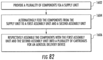
- an assembly method may include providing a plurality of components via a supply unit, alternatingly feeding a first portion of the components from the supply unit to a first assembly unit and a second portion of the components to a second assembly unit, and assembling the first portion of the components with the first assembly unit and the second portion of the components with the second assembly unit into a plurality of cartridges for an aerosol delivery device.
- alternatingly feeding the first portion of the components from the supply unit to the first assembly unit and the second portion of the components to the second assembly unit may include swiveling a rotary member between a first delivery position in which the rotary member is configured to deliver the first portion of the components to the first assembly unit and a second delivery position in which the rotary member is configured to deliver the second portion of the components to the second assembly unit.
- Swiveling the rotary member may include receiving one of the components from the supply unit in a first engagement head while a second engagement head feeds one of the components to the second assembly unit and receiving one of the components from the supply unit in the second engagement head while the first engagement head feeds one of the components to the first assembly unit.
- a system configured to assemble a plurality of cartridges for an aerosol delivery device.
- the system may include a plurality of assembly substations collectively configured to assemble a base and a plurality of additional components together.
- the base may extend between an inner end configured to receive the additional components during assembly of the cartridges and an attachment end defining an internal surface configured to engage a control body during usage of the aerosol delivery device.
- the system may further include a track extending between the assembly substations.
- the system may include a carriage configured to engage the track and to cooperate therewith to move between the assembly substations.
- the carriage may include an engagement head defining a plurality of sections configured to engage the internal surface of the attachment end of the base via an interference fit to provide the assembly substations with access to the inner end of the base to attach the additional components thereto.
- the carriage may define one or more alignment apertures and the track may include one or more locking pins configured to engage the alignment apertures to releasably lock the carriage at one or more of the assembly substations.
- the track further may further include a conveyor and a lifter mechanism.
- the lifter mechanism may include the locking pins and may be configured to lift the carriage from the conveyor.
- the carriage may include an electrostatic dissipative material.
- the carriage may further include a locator module including a ferromagnetic material.
- an assembly method may include providing a base and a plurality of additional components collectively configured to form a plurality of cartridges for an aerosol delivery device.
- the base may extend between an inner end configured to receive the additional components during assembly of the cartridges and an attachment end defining an internal surface configured to engage a control body during usage of the aerosol delivery device.
- the method may further include providing a plurality of assembly substations, a track, and a carriage comprising an engagement head defining a plurality of sections.
- the track may extend between the assembly substations, and the carriage may be configured to engage the track and to cooperate therewith to move between the assembly substations.
- the method may additionally include engaging the internal surface of the attachment end of the base with the sections of the engagement head via an interference fit to provide the assembly substations with access to the inner end of the base. Further, the method may include transporting the carriage by way of the track between the assembly substations and assembling the additional components with the inner end of the base at the assembly substations.
- engaging the base with the engagement head may include rotationally aligning the base with the engagement head.
- Rotationally aligning the base with the engagement head may include detecting a rotational orientation of the base based on image of the attachment end of the base.
- the method may include storing cartridge identification and status information in a storage module coupled to the carriage.
- the method may also include locking the carriage at one or more of the substations by directing one or more locking pins from the track into one or more alignment apertures defined in the carriage.
- Transporting the carriage by way of the track may include transporting the carriage by way of a conveyor, and wherein locking the carriage comprises lifting the carriage from the conveyor.
- the assembly substation may additionally include a suction system operably engaged with the outer body gripper of the robotic arm.
- the outer body gripper may be configured to apply a negative pressure supplied by the suction system longitudinally through the outer body to facilitate insertion of the partially-assembled cartridge into the outer body.
- the assembly substation may additionally include a bending mechanism configured to receive the partially-assembled cartridge therein so as to bend the liquid transport element against the negative heating terminal and the positive heating terminal.
- the assembly substation may also include a substrate gripper configured to wrap a reservoir substrate at least partially around the bending mechanism, The bending mechanism may be configured to retract relative to the partially-assembled cartridge following wrapping of the reservoir substrate such that the reservoir substrate is wrapped at least partially about the negative heating terminal and the positive heating terminal and in contact with the liquid transport element.
- the outer body gripper may include a piston.
- the piston may be in fluid communication with the suction system and configured to engage an end of the outer body to apply the negative pressure through the outer body.
- the piston may be configured to press the outer body into engagement with the base.
- the outer body gripper may be configured to receive the outer body therein while the bending mechanism receives the partially-assembled cartridge therein.
- the assembly method may further include inserting the partially-assembled cartridge in a bending mechanism to bend the liquid transport element against the negative heating terminal and the positive heating terminal.
- the assembly method may also include wrapping a reservoir substrate at least partially around the bending mechanism. Further, the assembly method may include retracting the bending mechanism relative to the partially-assembled cartridge following wrapping of the reservoir substrate such that the reservoir substrate is wrapped at least partially about the negative heating terminal and the positive heating terminal and in contact with the liquid transport element.
- applying the negative pressure to the outer body may include engaging an end of the outer body with a piston of the outer body gripper.
- the piston may be in fluid communication with the suction system and configured to apply the negative pressure through the outer body.
- the assembly method may additionally include pressing the outer body into engagement with the base with the piston.
- Embodiment 2 The assembly substation of any preceding or subsequent embodiment, wherein the feeder unit comprises a rotary member configured to swivel between a first delivery position in which the rotary member is configured to deliver the first portion of the components to the first assembly unit and a second delivery position in which the rotary member is configured to deliver the second portion of the components to the second assembly unit.
- Embodiment 4 The assembly substation of any preceding or subsequent embodiment, wherein the supply unit comprises a vibratory arrangement defining a pathway configured to arrange the components in a serially-aligned stream and a singulator configured to singulate the components from the serially-aligned stream.
- the supply unit comprises a vibratory arrangement defining a pathway configured to arrange the components in a serially-aligned stream and a singulator configured to singulate the components from the serially-aligned stream.
- Embodiment 5 The assembly substation of any preceding or subsequent embodiment, wherein the supply unit further comprises an actuator configured to individually remove the components from the serially-aligned stream or realign the components when misaligned in a first direction.
- Embodiment 8 The assembly method of any preceding or subsequent embodiment, wherein alternatingly feeding the first portion of the components from the supply unit to the first assembly unit and the second portion of the components to the second assembly unit comprises swiveling a rotary member between a first delivery position in which the rotary member is configured to deliver the first portion of the components to the first assembly unit and a second delivery position in which the rotary member is configured to deliver the second portion of the components to the second assembly unit.
- Embodiment 9 The assembly method of any preceding or subsequent embodiment, wherein swiveling the rotary member comprises receiving one of the components from the supply unit in a first engagement head while a second engagement head feeds one of the components to the second assembly unit and receiving one of the components from the supply unit in the second engagement head while the first engagement head feeds one of the components to the first assembly unit.
- Embodiment 10 The assembly method of any preceding or subsequent embodiment, wherein providing the components via the supply unit comprises directing the components along a pathway in a serially-aligned stream and singulating the components from the serially-aligned stream.
- Embodiment 11 The assembly method of any preceding or subsequent embodiment, further comprising individually removing the components from the serially-aligned stream or realigning the components when misaligned in a first direction.
- Embodiment 14 The system of any preceding or subsequent embodiment, wherein the assembly substations include a base load substation, the base load substation being configured to rotationally align the base with the engagement head of the carriage and engage the base with the engagement head.
- Embodiment 18 The system of any preceding or subsequent embodiment, wherein the track further comprises a conveyor and a lifter mechanism, the lifter mechanism comprising the locking pins and being configured to lift the carriage from the conveyor.
- Embodiment 21 An assembly method, comprising:
- Embodiment 24 The assembly method of any preceding or subsequent embodiment, wherein rotationally aligning the base with the engagement head comprises detecting a rotational orientation of the base based on image of the attachment end of the base.
- Embodiment 26 The assembly method of any preceding or subsequent embodiment, wherein transporting the carriage by way of the track comprises transporting the carriage by way of a conveyor, and wherein locking the carriage comprises lifting the carriage from the conveyor.
- Embodiment 27 An assembly substation, comprising:
- Embodiment 29 The assembly substation of any preceding or subsequent embodiment, wherein the outer body gripper is configured to receive the outer body therein while the bending mechanism receives the partially-assembled cartridge therein.
- Embodiment 30 The assembly substation of any preceding or subsequent embodiment, wherein the outer body gripper comprises a piston, the piston being in fluid communication with the suction system and configured to engage an end of the outer body to apply the negative pressure through the outer body.
- Embodiment 31 The assembly substation of any preceding or subsequent embodiment, wherein the piston is configured to press the outer body into engagement with the base.
- Embodiment 32 An assembly method, comprising:
- Embodiment 33 The assembly method of any preceding or subsequent embodiment, further comprising inserting the partially-assembled cartridge in a bending mechanism to bend the liquid transport element against the negative heating terminal and the positive heating terminal;
- Embodiment 34 The assembly method of any preceding or subsequent embodiment, wherein applying the negative pressure to the outer body comprises engaging an end of the outer body with a piston of the outer body gripper, the piston being in fluid communication with the suction system and configured to apply the negative pressure through the outer body.
- Embodiment 35 The assembly method of any preceding or subsequent embodiment, further comprising pressing the outer body into engagement with the base with the piston.
- the cartridge 200 and the control body 300 may be referred to as being disposable or as being reusable.
- the control body 300 may have a replaceable battery or a rechargeable battery and thus may be combined with any type of recharging technology, including connection to a typical alternating current electrical outlet, connection to a car charger (i.e., cigarette lighter receptacle), and connection to a computer, such as through a universal serial bus (USB) cable.
- the cartridge 200 may comprise a single-use cartridge, as disclosed in U.S. Pat. App. Pub. No. 2014/0060555 to Change et al. , which is incorporated herein by reference in its entirety.
- the indicator 318 may comprise one or more light emitting diodes.
- the indicator 318 can be in communication with the control component 312 through the connector circuit 320 and be illuminated, for example, during a user drawing on a cartridge coupled to the coupler 302, as detected by the flow sensor 310.
- the end cap 322 may be adapted to make visible the illumination provided thereunder by the indicator 318. Accordingly, the indicator 318 may be illuminated during use of the aerosol delivery device 100 to simulate the lit end of a smoking article.
- the indicator 318 can be provided in varying numbers and can take on different shapes and can even be an opening in the outer body (such as for release of sound when such indicators are present).
- the base shipping plug 202 may be configured to engage and protect the base 204 prior to use of the cartridge 200.
- the mouthpiece shipping plug 222 may be configured to engage and protect the mouthpiece 220 prior to use of the cartridge 200.
- the control component terminal 206, the electronic control component 208, the flow director 210, the atomizer 212, and the reservoir substrate 214 may be substantially entirely retained within the outer body 216.
- the label 218 may at least partially surround the outer body 216 and include information such as a product identifier thereon.
- the negative heating terminal 234 and the positive heating terminal 235 (e.g., positive and negative terminals) at the opposing ends of the heating element 240 are configured to form an electrical connection with the control body 300 when the cartridge 200 is connected thereto.
- the electronic control component 208 may form an electrical connection with the control body through the control component terminal 206.
- the control body 300 may thus employ the electronic control component 208 to determine whether the cartridge 200 is genuine and/or perform other functions. Further, various examples of electronic control components and functions performed thereby are described in U.S. Pat. App. Pub. No. 2014/009678 to Sears et al. , which is incorporated herein by reference in its entirety.
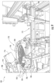
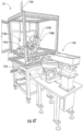
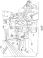
- FIG. 4 An example embodiment of the cartridge assembly subsystem 402 is schematically illustrated in FIG. 4 .
- the particular embodiments of substations and positions thereof may vary from those described below and illustrated in FIG. 4 .
- the particular operations employed as well as the order thereof may also vary.
- the equipment employed to assemble a cartridge may depend on the particular configuration of the end-product cartridge.
- the cartridge 200 described above and referenced hereinafter is discussed for example purposes only.
- the description generally refers to the portions of the cartridge assembly subsystem 402 as substations, it should be understood that the various assembly operations discussed herein may be performed by a single device, apparatus, or substation, or distributed across multiple devices, apparatuses, and substations.
- an indicator 730 may be illuminated to inform an operator that the base load substation 502 is running low on the bases 204, such that the operator may be informed that it is time to refill the vibratory hopper 708.
- the full sensor 726 and the low level sensor 728 may comprise optical sensors that include an emitter and a receiver configured to detect a presence or absence of a base 204 therebetween.
- FIG. 12 illustrates the rotary member 738 in a first receiving position
- FIG. 11 illustrates the rotary member in a second receiving position, between which the rotary member may be configured to swivel or rotate about a particular point.
- the first engagement head 740a In the first receiving position, the first engagement head 740a is positioned proximate the singulator 732. Thereby, a first base 204a may be singulated from the serially-aligned stream 720 and delivered into the first pocket 742a in the first engagement head 740a.
- a base load sensor 745 e.g., an optical sensor
- the carriage 604 may be directed past an initial locator sensor 758a configured to detect the locator module 626 and verify the presence and location of the carriage.
- An initial stop 760a may then stop the carriage 604 by engaging an initial stop pin 762a with the stop bar 628 on the carriage 604 (see, FIG. 7 ). Thereby, when a downstream carriage is clear, the carriage 604 may be released from the initial stop 760a by retracting the initial stop pin 762a.
- the substations downstream of the base load substation 502 may not perform additional operations that would be otherwise conducted on the first base 204a.
- the substations downstream of the base load substation 502 may not attempt to couple additional components to the base that should be on the carriage, so as to avoid damage to the remaining substations and waste of components.
- the second engagement head 740b is in the second receiving position at which the second engagement head is positioned proximate the singulator 732.
- one of the bases 204 may be singulated from the serially-aligned stream 720 and delivered into the second pocket 742b in the second engagement head 740b.
- the base load sensor 745 may detect that a base 204 (e.g., the second base 204b) has been delivered to the second engagement head 740b.
- the first engagement head 740a may feed the first base 204a received therein to the first assembly unit 706a in the manner described above.
- the rotary member 738 may then swivel (e.g., by rotating counterclockwise when viewed from above) back to the first receiving position such that the first engagement head 740a may receive another base 204.
- the second engagement head 740b may feed the second base 204b received therein to the second assembly unit 706b. Accordingly, the rotary member 738 may swivel back and forth such that the bases are individually delivered by the feeder unit 704 to the first assembly unit 706a and the second assembly unit 706b.
- the first receiving position may correspond to the second delivery position and the second receiving position may correspond to the first delivery position.
- the second assembly unit 706b may engage the second base 204b with the second engagement head 608b in the manner described above with respect to the first assembly unit 706a.
- the second robotic arm 746b may engage the second base 204b via the second end effector 748b, lift and rotate the second base to the proper orientation based on an image provided by the second rotational alignment imaging device 750b, and engage the second base with the second engagement head 608b in the proper orientation while the lifter mechanism 770b engages the carriage 604.
- the second end effector 746b may stop applying negative pressure, such that the second base 204b may release therefrom and remain in engagement with the second engagement head 608b.
- the second robotic arm 746b may return to an initial position proximate the rotary member 738.
- a second storage transceiver 776b may write code to the storage module 624 indicating whether or not the second base 204b was properly coupled to the second engagement head 608b.
- a component presence sensor 778b e.g., comprising a light emitter and receiver; see FIG. 15
- the component presence sensor 778b may detect whether or not the base 204b is present while the carriage 604 is lifted by the lifter mechanism 770b.
- the substations downstream of the base load substation 502 may not perform additional operations that would be otherwise conducted on the second base so as to avoid damage to the remaining substations and waste of components.
- the supply unit 802 may further comprise an orientation sensor 822 (e.g., a camera) configured to determine an alignment of the control component terminals 206 on the pathway 818, and the actuator 824 may be actuated in response thereto when a misaligned control component terminal is detected.
- an orientation sensor 822 e.g., a camera
- each of the control component terminals 206 in the serially-aligned stream 820 may be properly oriented downstream of the actuator 824.
- the control component terminals 206 removed by the actuator 824 may be directed back into the vibratory bowl 810 such that the control component terminals may be returned to the pathway 818.
- the pathway may define a gap or other feature configured to remove the components from the serially-aligned stream when the components are misaligned in a second direction.
- longitudinally oriented control component terminals 206 may fall through the gap 818a in the pathway 818 (see, FIG. 19 ).
- the supply unit 802 may include a singulator 832 configured to singulate the control component terminals 206 from the serially-aligned stream 820.
- the singulator 832 may include a stop 834 that stops the serially-aligned stream 820 of control component terminals 806 from further advancement.
- the singulator 832 may include a horizontal actuator 836. As illustrated in FIG. 21 , the horizontal actuator 836 may be configured to horizontally displace a terminal plunger 838 to singulate one of the control component terminals 206 from the serially-aligned stream 820.
- FIG. 22 illustrates a perspective view of the first assembly unit 806a and the second assembly unit 806b.
- the first assembly unit 806a may include a first robotic arm 846a and a first end effector 848a coupled thereto.
- the second assembly unit 806b may include a second robotic arm 846b and a second end effector 848b coupled thereto.
- the first end effector 848a may be configured to engage the control component terminal 206. As illustrated in FIG. 23 , in some embodiments the first end effector 848a may comprise first and second opposing portions 850, 852 configured to clamp the upper end 252 of the control component terminal 206 therebetween. Accordingly, the first end effector 848a may be configured to securely grasp each control component terminal 206.
- first end effector 848a may be configured to rotate between a horizontal configuration employed to grasp and remove the control component terminal 206 from the singulator 832 and a vertical configuration (see, FIG. 23 ) configured to insert the control component terminal into the first base 204a.
- FIG. 22 illustrates the first end effector 848a at an angle between the horizontal configuration and the vertical orientation during transition therebetween. Accordingly, the first robotic arm 846a and the first end effector 848a may prepare the control component terminal 206 for insertion into the base 204.
- a carriage 604 with the first and second bases 204a, 204b engaged therewith may be directed through the control component terminal coupling substation 504.
- the track 602 may direct each carriage 604 through a first processing portion 854a of the first assembly unit 806a and a second processing portion 854b of the second assembly unit 806b at the base load substation 502.
- each carriage 604 may first be directed through the first processing portion 854a followed by the second processing portion 854b. Operations relating to the first base 204a and a first control component terminal 206a are conducted at the first processing portion 854a, whereas operations relating to the second base 204b and a second control component terminal 206b (see, FIG. 25 ) are conducted at the second processing portion 854b.
- the first end effector 848a may release the first control component terminal 206a, such that the first control component terminal may remain in engagement with the first base 204a.
- the first robotic arm 846a may then return to the singulator 832 to engage an additional control component terminal for attachment with the first base on a subsequent carriage.
- a storage transceiver 876a may write code to the storage module 624 indicating whether or not the first control component terminal 206a was properly coupled to the first base 204a.
- a component presence sensor 878a e.g., comprising a light emitter and receiver
- the component presence sensor 878a may detect whether or not the first control component terminal 206a is present while the carriage 604 is lifted by the lifter mechanism 870a.
- a second storage transceiver 876b may write code to the storage module 624 indicating whether or not the second control component terminal 206b was properly engaged with the second base 204b.
- a component presence sensor 878b e.g., comprising a light emitter and receiver
- the component presence sensor 878b may detect whether or not the second control component terminal is present while the carriage 604 is lifted by the lifter mechanism 870b.
- a storage transceiver 876c may write code to the storage module 624 indicating whether or not the control component terminals 206a, 206b were properly pressed into the bases 204a, 204a (e.g., based on completion of a full downward stroke of the press 880).
- the press 880 may press the control component terminals 206a, 206b into full engagement with the bases 204a, 204b while other operations are ongoing, such as while the first robotic arm 846a couples the first control component terminal 206a to the first base 204a and the second robotic arm 846b receives the second control component terminal 206b from the singulator 832. Accordingly, rapid and efficient engagement of the control component terminals 206a, 206b with the bases 204a, 204b may be achieved.
- the negative heating terminal coupling substation 506 and the positive heating terminal coupling substation 508 may be positioned downstream from the control component terminal coupling substation 504.
- the negative heating terminal coupling substation 506 may be positioned downstream from the control component coupling substation 506 and the positive heating terminal coupling substation 508 may be positioned downstream of the negative heating terminal coupling substation.
- the negative heating terminal coupling substation 506 and the positive heating terminal coupling substation 508 may be substantially similar.
- the description provided below is directed to the negative heating terminal coupling substation 506, such description is applicable to both the negative heating terminal coupling substation and the positive heating terminal coupling substation 508, except as otherwise noted.
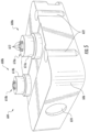
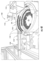
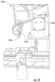
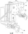
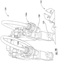
- FIG. 27 illustrates a perspective view of the negative heating terminal coupling substation 506.
- the negative heating terminal coupling substation 506 may include a supply unit 902, a feeder unit 904, a first assembly unit 906a, and a second assembly unit 906b.
- the supply unit 902 may be configured to provide a plurality of components (e.g., the negative heating terminals 234).
- the feeder unit 904 may be configured to receive the negative heating terminals 234 from the supply unit and alternatingly feed the negative heating terminals to the first assembly unit 906a and the second assembly unit 906b.
- the first assembly unit 906a and the second assembly unit 906b may each be configured to assemble the negative heating terminals 234 into cartridges 200 for an aerosol delivery device 100, for example, by engaging the negative heating terminals with the bases 204.
- the supply unit 902 may include a singulator 932 configured to singulate the negative heating terminals 234 from the serially-aligned stream 920.
- the singulator 932 may include a stop 934 (e.g., comprising a pin) that stops the serially-aligned stream 920 of negative heating terminals 234 from further advancement.
- a horizontal actuator 936 (see, FIG. 30 ) may be configured to move the stop 934 horizontally between a retracted position and an extended position. The horizontal actuator 936 may default to the extended position such that the stop 934 blocks the serially-aligned stream 920 of negative heater terminals 234 from moving.
- a biasing member 940 may engage the outermost negative heating terminal 234 such that the outermost negative heating terminal 234 is further separated from the remaining negative heating terminals.
- the biasing member 940 may be configured to extend upwardly to engage the downwardly-extending upper end 258 of the outermost negative heating terminal 234.
- the biasing member 940 may define an angled surface 942 that engages and presses outwardly on the upper end 258 of the outermost negative heating terminal 234 as the biasing member 940 extends upward.
- the first end effector 962 may be configured to engage the first negative heating terminal 234a.
- the first end effector 962a may comprise first and second opposing portions 964, 966 configured to clamp the first negative heating terminal 234a therebetween. Accordingly, the first end effector 962a may be configured to securely grasp each first negative heating terminal 234a.
- the singulator 932 may supply the first negative heating terminals 234a upside down, with the upper end 258 thereof pointing downwardly, and this orientation may be maintained by the supply unit 904, such that the first end effector 962a receives the first negative heating terminals in this inverted orientation.
- the first end effector 962a may grasp each first negative heating terminal 234a between the upper end 258 and the lower end 260, substantially at a middle thereof. The first end effector 962a may thereby rotate one hundred eighty degrees such that the lower end 260 of the first negative heating terminal 234a is pointed downwardly, as illustrated in FIG. 33 .
- Operations relating to the first base 204a and the first negative heating terminals 234a are conducted at the first processing portion 968a, whereas operations relating to the second base 204b and the second negative heating terminals 234b (see, e.g., FIG. 30 ) are conducted at the second processing portion 968b.
- a storage transceiver (not shown; see, e.g., storage transceiver 984b) may write code to the storage module 624 indicating whether or not the first negative heating terminal 234a was properly coupled to the first base 204a.
- a component presence sensor 986a e.g., comprising a light emitter and receiver
- the component presence sensor 986a may detect whether or not the first negative heating terminal 234a is present while the carriage 604 is lifted by the lifter mechanism 980a.
- the second negative heating terminal 234b may be singulated from the serially-aligned stream 920 of negative heating terminals.
- the second horizontal actuator 956 may extend the second stop 938 to the default extended configuration, the biasing member 940 may retract, and the horizontal actuator 936 (i.e., the first horizontal actuator) may retract the first stop 934 such that a negative heating terminal 234 (i.e., the second negative heating terminal 234b) advances to the second stop 938.
- the second gripper 948b of the feeder unit 904 may engage the second negative heating terminal 234b.
- the feeder unit 904 may swivel (e.g., by rotating counterclockwise when viewed from above), and position the second negative heating terminal 234b proximate the track 602.
- the second robotic arm 960b, the second end effector 962b, and a second pusher may then engage the second negative heating terminal 234b in the negative heating terminal aperture 248b of the second base 204b in the manner described above.
- the second storage transceiver 984b may write code to the storage module 624 indicating whether or not the second negative heating terminal 234b was properly engaged with the second base 204b.
- a component presence sensor 986b e.g., comprising a light emitter and receiver
- the component presence sensor 986b may detect whether or not the second negative heating terminal 234b is present while the carriage 604 is lifted by the lifter mechanism 980b.
- the first robotic arm 960a may receive the first negative heating terminal 234a from the rotary member 944. Accordingly, rapid and efficient engagement of the negative heating terminals 234a, 234b with the bases 204a, 204b may be achieved.
- the positive heating terminal coupling substation 508 may be substantially similar to the negative heating terminal coupling substation 506. Accordingly, a description of the various components of the positive heating terminal coupling substation 508 will not be repeated. However, in some embodiments the positive heating terminal coupling substation 508 may additionally include an inspection unit 988, which may be positioned downstream of the first and second assembly units thereof, which may be substantially similar to the first and second assembly units 906a, 906b of the negative heating terminal coupling substation 506, as noted above.
- the inspection unit 988 may include an inspection locator sensor 990, which may detect the presence of the carriage 604.
- a first inspection stop 992 may momentarily stop the carriage at a location at which the first base 204a is positioned proximate an imaging device 994 (e.g., a digital camera). Accordingly, the imaging device 994 may capture an image of the first control component terminal 206a, the first negative heating terminal 234a, and a first positive heating terminal (see, e.g., positive heating terminal 235 in FIG. 1 ).
- the carriage 604 may travel downstream on the track 602 and engage a second inspection stop 996, at which the second base 204b is positioned proximate the imaging device 994. Accordingly, the imaging device 994 may capture an image of the second control component terminal 206b, the second negative heating terminal 234b, and a second positive heating terminal (see, e.g., positive heating terminal 235 in FIG. 1 ).
- a backlight 998 may be positioned across from the imaging device 994, such that the terminals 206, 234, 235 are positioned between the imaging device and the backlight, to improve imaging of the terminals. Accordingly, the images captured by the imaging device 994 may be analyzed to determine whether the terminals 206, 234, 235 are missing or improperly engaged with the bases 204. For example, the height to which the terminals 206, 234, 235 extend from the base 204 may be determined and compared to a desired height of the terminals.
- a third storage transceiver 984c may write code to the storage module 624 indicating whether or not the terminals 206, 234, 235 are properly engaged with the bases 204.
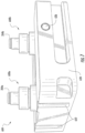
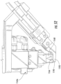
- the control component coupling substation 510 may be positioned downstream of the positive heating terminal coupling substation 508.
- FIG. 36 illustrates a perspective view of the control component coupling substation 510.
- the control component coupling substation 510 may include a supply unit 1002, a feeder unit 1004, a first assembly unit 1006a, and a second assembly unit 1006b.
- the supply unit 1002 may be configured to provide a plurality of components (in particular, electronic control components 208).
- the feeder unit 1004 may be configured to receive the electronic control components 208 from the supply unit and alternatingly feed the electronic control components 208 to the first assembly unit 1006a and the second assembly unit 1006b.
- the first assembly unit 1006a and the second assembly unit 1006b may each be configured to assemble the electronic control components 208 into cartridges 200 for an aerosol delivery device 100 (e.g., by engaging the electronic control components with the control component terminals 206).
- the supply unit 1002 may further comprise an orientation sensor 1028 (e.g., a camera) configured to determine an alignment of the electronic control components 208 on the pathway 1018, and the actuator 1024 may be actuated in response thereto when a misaligned electronic control component is detected.
- an orientation sensor 1028 e.g., a camera
- each of the electronic control components 208 may define a first longitudinal end 262 and a second longitudinal end 264.
- the first longitudinal end 262 may be oriented downstream of the second longitudinal end 264 in a proper orientation for performance of additional operations on the electronic control component 208 as described hereinafter.
- electronic control components defining a different orientation, as detected by the orientation sensor 1028 may be removed from the pathway 1018 by the nozzle 1026.
- the track 602 may move the carriage 604 such that the first base 204a is positioned for receipt of the first electronic control component 208a.
- a carriage 604 with the bases 204 engaged therewith, and the negative heating terminal 234, the positive heating terminal 235, and the control component terminal 206 engaged with the bases may be directed through the control component coupling substation 510.
- the track 602 may direct each carriage 604 through a first processing portion 1060a of the first assembly unit 1006a and a second processing portion 1060b of the second assembly unit 106b at the control component coupling substation 510.
- each carriage 604 may first be directed through the first processing portion 1060a followed by the second processing portion 1060b.
- Operations relating to the first base 204a and the first electronic control component 208a are conducted at the first processing portion 1060a, whereas operations relating to the second base 204b and the second electronic control component 208b (see, FIG. 40 ) are conducted at the second processing portion 1060b.
- a carriage 604 may be transported along the track 502 to the first processing portion 1060a.
- the carriage 604 may be directed past a carriage sensor 1062a, which may comprise a light emitter and detector, and which detects the presence of the carriage 604.
- the carriage 604 may be directed past an initial locator sensor 1064a configured to detect the locator module 626 and verify the presence and location of the carriage.
- An initial stop 1066a may then stop the carriage 604 in the manner described above with respect to the initial stop 760a of the base load substation 502 (see, FIG. 15 ). Thereafter, when any downstream carriage is clear, the carriage 604 may be released from the initial stop 1066a.
- the pivoting gripper 1074a may stop applying the negative pressure to the first electronic control component 208a, such that the first electronic control component remains in engagement with the control component terminal 206a between the negative and positive heating terminals 234a, 235a.
- the first robotic arm 1052a may then return to the feeder unit 1004 to engage an additional first electronic control component for attachment with the first base 204a on a subsequent carriage 604.
- a storage transceiver 1078a may write code to the storage module 624 indicating whether or not the first electronic control component 208a was properly coupled to the first base 204a.
- the storage transceiver 1078a may store information to the storage module 624 indicating that the electronic control component 208a is improperly attached unless each of the movements of the components of the first assembly unit 1006a are successfully completed, as detected by various motion sensors associated therewith.
- the substations downstream of the control component coupling substation 510 may not perform additional operations that would be otherwise conducted on the first base 204a.
- the substations downstream of the electronic control component coupling substation 510 may not attempt to couple additional components thereto, so as to avoid damage to the remaining substations and waste of components.
- the storage transceiver 1078a may read the code on the storage module 624 to determine that the partially-assembled cartridge is fit for further assembly prior to coupling the electronic control component 208a to the control component terminal 206 coupled to the first base 204a.
- the second processing portion 1060b may comprise the same components included in the first processing portion 1060a.
- the second processing portion 1060b may include a carriage sensor 1062b (see, FIG. 42 ), an initial locator sensor 1064b, an initial stop 1066b, a lift stop 1068b, a stop locator sensor 1070b, a lifter mechanism 1072b, and a storage transceiver 1078b. Accordingly, the second processing portion 1060b may operate in substantially the same manner as the first processing portion 1068a, and hence the description thereof will not be repeated.
- the second electronic control component 208b may be singulated from the serially-aligned stream 1020 of electronic control components in the manner described above and received in the second pocket 1046b in the second engagement head 1044b, as illustrated in FIG. 41 .
- the second electronic control component 208b may be received by the second assembly unit 1006b, which may then engage the second electronic control component 208b with the second base 204b in the manner described above.
- the lifter mechanism 1072b may lower the carriage 604 such that the track 602 transports the carriage downstream.
- an inspection unit 1080 may be positioned downstream of the second assembly unit 1006b.
- the inspection unit 1080 may include an inspection locator sensor 1082, which may detect the presence of the carriage 604.
- a lift stop 1084 may momentarily stop the carriage 604 at a location at which a lifter mechanism 1086 may lift the carriage 604 after the carriage is detected by the inspection locator sensor 1082.
- first and second component presence sensors 1088a, 1088b may detect the presence of the electronic control components 208a, 208b. Accordingly, a storage transceiver 1090 may write code to the storage module 624 indicating whether or not the electronic control components 208a, 208b are properly attached to a respective base 204a, 204b. In instances in which the electronic control components 208a, 208b are not properly engaged with a respective base 204a, 204b, the substations downstream of the control component coupling substation 510 may not perform additional operations that would be otherwise conducted on the base.
- the lifter mechanism 1086 may lower the carriage 604 such that the track 602 transports the carriage including the positive and negative heating terminals 234, 235, the control component terminal 206, and the electronic control component 208 respectively coupled to bases 204a, 204b downstream.
- the above-described operations may be conducted simultaneously.
- the second engagement head 1044b may receive the second electronic control component 208b from the singulator 1036.
- the first engagement head 1044a may receive the first electronic control component 208a from the singulator 1036.
- the first robotic arm 1052a couples the first electronic control component 208a to the first base 204a
- the second robotic arm 1052b may receive the second electronic control component 208b from the second engagement head 1044a.
- the first robotic arm 1052a may receive the first electronic control components 208a from the first engagement head 1044a. Accordingly, rapid and efficient engagement of the electronic control components 208a, 208b with the bases 204a, 204b may be achieved.
- the first assembly unit 1106a and the second assembly unit 1106b may each be configured to assemble the flow directors 210 into cartridges 200 for an aerosol delivery device 100, for example by positioning the flow directors between the negative and positive terminals 234, 235 and in engagement with the control component terminal 208.
- the flow directors 210 may be loaded directly into the vibratory bowl 1110, or a vibratory hopper 1114 may supply the flow directors 210 to the vibratory bowl in the manner described above.
- a component level sensor 1116 may activate vibration of the vibratory hopper 1114 based on the level of the flow directors 210 within the vibratory bowl 1110.
- the vibratory bowl 1110 may define a pathway 1118 configured to arrange the flow directors 210 in a serially-aligned stream 1120 (see, FIG. 49 ).
- the vibratory motion of the vibratory bowl 1110 may direct the flow directors 210 upwardly along the pathway 1118, which may narrow such that some flow directors fall therefrom and the flow directors that remain on the pathway become serially-aligned.
- the vibratory bowl 1110 may be configured to arrange the flow directors 210 generally vertically by the time the flow directors reach the supply track 1112.
- An actuator or gap (not shown) may be configured to individually remove or realign the flow directors 210 in the serially-aligned stream 1120 when the flow directors are misaligned in a direction, as discussed above.
- the supply track 1112 may include a full sensor 1132 configured to detect whether the supply track is full of the flow directors 210 and to thereby turn off the vibration of the vibratory bowl 1110, and a low level sensor 1134 configured to detect when the supply track is running low on the flow directors 210, to active an indicator 1130 (see, FIG. 47 ) to inform an operator that the flow director coupling substation 510 is running low on the flow directors.
- the full sensor 1132 and the low level sensor 1134 may comprise optical sensors that include an emitter and a receiver configured to detect whether a flow director 210 is positioned therebetween.
- the vertical actuator 1140 may momentarily retract the stop 1138 to the retracted position to allow one of the flow directors 210 to pass the stop.
- the vertical actuator 1140 may return the stop 1138 to the extended position inside of the subsequent flow director 210 after the outermost flow director passes thereunder.
- the flow director may contact a second stop 1144.
- a second vertical actuator 1146 may extend a guide pin 1148 into the longitudinal hole 210' extending through the flow director 210.
- the guide pin 1148 may guide the flow director 210 to the feeder unit 1104, such that the flow director is singulated from the serially-aligned stream 1120, and received by the feeder unit 1104.
- the feeder unit 1104 may comprise a rotary member 1152 having a first engagement head 1154a including a first pocket 1156a and a second engagement head 1154b including a second pocket 1156b each configured to receive one of the flow directors 210 from the supply unit 1102.
- the rotary member 1152 may comprise a first arm 1158a to which the first engagement head 1154a is mounted and a second arm 1158b to which the second engagement head 1154b is mounted.
- FIGS. 49 and 50 illustrate the rotary member 1152 in a first receiving position at which the first engagement head 1154a is positioned proximate the singulator 1136.
- the rotary member 1152 may be configured to swivel to a second receiving position at which the second engagement head 1154b is positioned proximate the singulator 1136.
- a singulation sensor 1160 e.g., an optical sensor
- the rotary member 1152 may swivel between the first receiving position (corresponding to a second delivery position) and a second receiving position (corresponding to a first delivery position) in the manner described above with respect to the other rotary members described herein.
- the singulated flow directors 210 may be delivered to the first assembly unit 1106a and the second assembly unit 1106b.
- FIG. 51 illustrates the second assembly unit 1106b.
- the second assembly unit 1106b may include a second robotic arm 1162b and a second end effector 1164b.
- the first assembly unit 1106a may include a first robotic arm 1162a (see, FIG. 47 ) and a first end effector 1164a (see, FIG. 52 ).
- the first end effector 1154b may be configured to engage a first flow director 210a (see, FIG.
- the first end effector 1154a may comprise first and second opposing portions 1166, 1168 configured to clamp the first flow director 210a therebetween.
- the track 602 may move the carriage 604 such that the first base 204a is positioned for receipt of the first flow director 210a and similarly, the second base 204b is positioned for receipt of the second flow director 210b.
- the track 602 may direct each carriage 604 through a first processing portion 1170a and a second processing portion 1170b at the flow director coupling substation 512.
- the first processing portion 1170a may include a carriage sensor (not shown; see, e.g., carriage sensor 1172b), an initial locator sensor 1174a, an initial stop 1176a, a lift stop 1178a, a stop locator sensor 1180a, and a lifter mechanism 1182a, which may function in the manner described above with respect to the same components at the other substations.
- the terminal pinchers 1190, 1192 may pinch the negative and positive heating terminals against the side of the first flow director 208a, such that the flow director is securely positioned therebetween.
- the lifter mechanism 1182a may lower the carriage 604 back onto the track 602.
- the carriage 604 may be directed downstream to the second processing portion 1170b, at which the second assembly unit 1106b may perform substantially the same operations discussed above with respect to the first assembly unit 1106a on the second base 204b, with the exception of terminal spreading which is conducted upstream at the terminal spreader 1184.
- the second processing portion 1170b at which the second assembly unit 1106b may perform substantially the same operations discussed above with respect to the first assembly unit 1106a on the second base 204b, with the exception of terminal spreading which is conducted upstream at the terminal spreader 1184.
- the above-described operations may be conducted simultaneously.
- the second engagement head 1154b may receive the second flow director 210b from the singulator 1136.
- the first engagement head 1154a may receive the first flow director 210a from the singulator 1136.
- the first robotic arm 1162a couples the first flow director 210a to the first base 204a
- the second robotic arm 1162b may receive the second flow director 210b from the second engagement head 1154b.
- the first robotic arm 1162a may receive the first flow director 210a from the first engagement head 1154a. Accordingly, rapid and efficient engagement of the flow directors 210a, 210b with the bases 204a, 204b may be achieved.
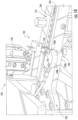
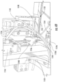
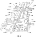
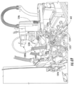
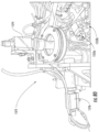
- the heating element coupling substation 514 may be positioned downstream of the flow director coupling substation 512.
- FIG. 54 illustrates a perspective view of the heating element coupling substation 514.
- the heating element coupling substation 514 may include a supply unit 1202.
- the supply unit 1202 may include a spool 1204 configured to supply a substantially continuous heating element input 1206.
- the substantially continuous heating element input 1206 may comprise a plurality of the heating elements 240 wound about an elongated liquid transport element 238, which may thereby be cut as described below to define a plurality of liquid transport elements 238 with a heating element 240 coupled thereto. Examples of heating elements wound about liquid transport elements are provided in U.S. Pat. App. Pub. Nos. 2014/0270730 to DePiano et al. and 2014/0157583 to Ward et al. , which are incorporated herein by reference in their entireties.
- the heating element coupling substation 514 may further include a casing 1208.
- the casing 1208 may be substantially enclosed and opaque so as to prevent laser beams/and or other potentially harmful light from exiting therefrom.
- welding and in particular laser welding, in addition to the various other operations discussed below, may be performed inside the casing 1208.
- FIG. 55 illustrates a view of a portion of the supply unit 1202 inside of the casing 1208.
- the supply unit 1202 may further comprise a moveable clamp 1210 configured to pull the substantially continuous heating element input 1206 from the spool 1204 into the casing 1206.
- the supply unit 1202 may additionally include a guide 1212 and a singulator 1214, which may comprise a cutter.
- the substantially continuous heating element input 1206 may be directed through the guide 1212 (e.g., through an aperture defined therethrough) and through the singulator 1214 to a feeder unit 1216.
- the supply unit 1202 may be configured to pull the substantially continuous heating element input 1206 until a desired length thereof is received by the feeder unit 1216.
- at least one imaging device may be configured to determine a length of the substantially continuous heating element input 1206 pulled from the spool 1202.
- the supply unit 1202 may include a first imaging device 1226a and the feeder unit may include a second imaging device 1226b.
- the first imaging device 1226a may determine a position of a heater area defined by the heating element 240 (e.g., a portion of the heating element at which a plurality of tightly-wound coils are positioned), and the moveable clamp 1210 may align a center of the heater area with the second imaging device 1226b.
- the moveable clamp 1210 may pull the substantially continuous heating element input 1206 from the spool 1204 and direct the substantially continuous heating element input through the second engagement head 1218b such that the second gripper 1220b may engage an end thereof.
- a second heating element 240 and second liquid transport element 238 may be singulated from the substantially continuous heating element input 1206 by the singulator 1214 in the manner described above.
- FIG. 59 illustrates an enlarged view of the first engagement head 1218a, which may be substantially similar to the second engagement head 1218b.
- the first engagement head 1218a may include a plurality of depressible buttons 1244.
- the buttons 1244 may be configured to recess into the first engagement head 1218a when engaged by the prongs 1240, 1242 of each of the opposing portions 1236, 1238 of the end effector 1234a.
- the first processing portion 1244a may include a terminal fixation mechanism 1258a and a laser 1260a.
- FIG. 61 illustrates an enlarged view of the terminal fixation mechanism 1258a.
- the terminal fixation mechanism 1258a may include a clamp 1262a.
- the clamp 1262a may include opposing terminal effectors 1264a and opposing base effectors 1266a coupled thereto. Accordingly, when the carriage 604 is lifted by the lifter mechanism 1256a, the clamp 1262a may act on the first base 204a and the negative and positive heating terminals 234a, 235a coupled thereto.
- the base effectors 1266a may clamp on opposing sides of the first base 204a such that the first base is centered therebetween. Further, the terminal effectors 1264a may clamp against opposing sides of the negative heating terminal 234a and the positive heating terminal 235a.
- a center portion 1272c of the protruding member 1268 may extend between the negative and positive heating terminals 234a, 235a.
- outer prongs 1274c defined by the recessed member 1270 may extend around the outside of the negative and positive heating terminals 234a, 235a. Accordingly, the center portion 1272c of the protruding member 1268 and the outer prongs 1274c of the recessed member 1270 may position the negative and positive heating terminals 234a, 235a at a fixed spacing corresponding to a desired spacing of the negative and positive heating terminals for attachment of the heating element 240 thereto.
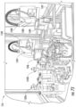
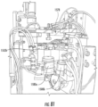
- the outer body supply unit 1306 may supply the outer bodies 216 (see, e.g., FIG. 1 ).
- the outer body supply unit 1306 may include a vibratory arrangement.
- the vibratory arrangement may include a vibratory bowl 1330 and a supply track 1332.
- the vibratory bowl 1330 and/or the supply track 1332 may be manufactured by Performance Feeders, Inc. of Oldsmar, FL.
- the supply track 1332 may include a full sensor 1342 configured to detect whether the supply track is full of the outer bodies 216 and to thereby turn off the vibration of the vibratory bowl 1330, and a low level sensor (not shown; see, e.g., the full sensor 1342) configured to detect when the supply track 1332 is running low on the outer bodies 216, to active an indicator 1346 (see, FIG. 63 ) to inform an operator that the reservoir and outer body coupling substation 516 is running low on the outer bodies 216.
- the full sensor 1342 and the low level sensor may comprise optical sensors that include an emitter and a receiver configured to detect each outer body 216 passing thereby.
- the indicator 1346 may alternatively or additionally be activated when one or both of the spools 1308a, 1308b runs low on the substantially continuous reservoir substrate input 1310.
- the first and second outer body and reservoir substrate feeders 1370a, 1370b may each include a rotary member 1372, first and second substrate grippers 1374', 1374" positioned at opposing ends of the rotary member, and first and second outer body supporters 1376', 1376" positioned at opposing ends of the rotary member.
- the outer body supporters 1376', 1376" may comprise upwardly extending pins.
- the engagement heads 1362a, 1362b of the initial body feeder 1360 may position and release the outer bodies 216 such that the outer body extenders 1376', 1376" extend at least partially through the outer bodies such that the outer bodies may be held in place.
- the rotary member 1372 may rotate such that the reservoir substrate and the outer body are positioned for receipt by a respective one of a first assembly unit 1380a and a second assembly unit 1380b, as illustrated in FIG. 69 .
- the first outer body and reservoir substrate feeder 1370a supplies the outer bodies 216 and reservoir substrates 214 to the first assembly unit 1380a and the second outer body and reservoir substrate feeder 1370b (see, FIG. 71 ) supplies the outer bodies and the reservoir substrates to the second assembly unit 1380b.
- the second assembly unit 1380b is positioned upstream of the first assembly unit 1380a. Accordingly, a reservoir substrate 214 and an outer body 216 may be assembled to the second partially-assembled cartridge including the second base 204b in advance of assembling a reservoir substrate and an outer body to the first partially-assembled cartridge including the first base 204a. However, as may be understood, this order may be reversed in other embodiments.
- the second processing portion 1382b may include a carriage sensor (not shown; see, e.g., carriage sensor 1384a), an initial locator sensor 1386b, an initial stop 1388b, a lift stop 1390b (not shown; see, e.g. lift stop 1390a in FIG. 70 ), a stop locator sensor 1392b, and a lifter mechanism 1394b.
- the carriage 604 may be directed along the track 602 to the second processing portion 1382b at which the second assembly unit 1380b assembles the reservoir substrate 214 and the outer body 216 to the second base 204b followed by the first processing portion 1382a at which the first assembly unit 1380a assembles the reservoir substrate and the outer body to the first base 204a.
- the indexing table 1550 is illustrated as rotated slightly counterclockwise from first angular stop 1554 at which the grippers 1552a, 1552b receive the partially-assembled cartridges from the first transfer unit 1504, so as to show the first reject chute 1556.
- the grippers 1552a, 1552b are positioned over the reject chute 1556, instead of displaced therefrom, in the first angular stop 1554.
- the indexing table 1550 may next index to a fourth angular stop 1578.
- the fourth angular stop 1578 may include first and second electrical testers 1580a, 1580b.
- the electrical testers 1580a, 1580b may be configured to ensure that the heating element 240 was properly welded to the negative and positive heating terminals 234, 235. Further, the electrical testers 1580a, 1580b may test the partially-assembled cartridges to make sure that the control component terminal 206, the negative heating terminal 234, and the positive heating terminal 235 are not grounded to the outer body 216. Further, in some embodiments the electrical testers 1580a, 1580b may upload code to the electronic control component 208 which may, for example, control a heating profile dictating how current is directed to the heating element 240 when a draw is detected on an associated control body.
- the non-transitory computer readable medium may comprise program code instructions for providing a plurality of components via a supply unit; program code instructions for alternatingly feeding a first portion of the components from the supply unit to a first assembly unit and a second portion of the components to a second assembly unit via a processor; and program code instructions for assembling the first portion of the components with the first assembly unit and the second portion of the components with the second assembly unit into a plurality of cartridges for an aerosol delivery device.
- the program code instructions for applying the negative pressure to the outer body may comprise program code instructions for engaging an end of the outer body with a piston of the outer body gripper, the piston being in fluid communication with the suction system and configured to apply the negative pressure through the outer body.
- the non-transitory computer readable medium may further comprise program code instructions for pressing the outer body into engagement with the base with the piston.
Landscapes
- Engineering & Computer Science (AREA)
- Mechanical Engineering (AREA)
- Automatic Assembly (AREA)
- Charge And Discharge Circuits For Batteries Or The Like (AREA)
- Packaging Of Annular Or Rod-Shaped Articles, Wearing Apparel, Cassettes, Or The Like (AREA)
- Containers And Packaging Bodies Having A Special Means To Remove Contents (AREA)
- Feeding Of Articles To Conveyors (AREA)
Applications Claiming Priority (3)
| Application Number | Priority Date | Filing Date | Title |
|---|---|---|---|
| US14/716,112 US10238145B2 (en) | 2015-05-19 | 2015-05-19 | Assembly substation for assembling a cartridge for a smoking article |
| EP16725342.6A EP3297465B1 (de) | 2015-05-19 | 2016-05-18 | Verfahren zum zusammenbau einer kartusche für einen rauchartikel sowie zugehöriges system und vorrichtung |
| PCT/US2016/033073 WO2016187297A2 (en) | 2015-05-19 | 2016-05-18 | Method for assembling a cartridge for a smoking article, and associated system and apparatus |
Related Parent Applications (1)
| Application Number | Title | Priority Date | Filing Date |
|---|---|---|---|
| EP16725342.6A Division EP3297465B1 (de) | 2015-05-19 | 2016-05-18 | Verfahren zum zusammenbau einer kartusche für einen rauchartikel sowie zugehöriges system und vorrichtung |
Publications (2)
| Publication Number | Publication Date |
|---|---|
| EP4397435A2 true EP4397435A2 (de) | 2024-07-10 |
| EP4397435A3 EP4397435A3 (de) | 2024-09-11 |
Family
ID=56081622
Family Applications (2)
| Application Number | Title | Priority Date | Filing Date |
|---|---|---|---|
| EP16725342.6A Active EP3297465B1 (de) | 2015-05-19 | 2016-05-18 | Verfahren zum zusammenbau einer kartusche für einen rauchartikel sowie zugehöriges system und vorrichtung |
| EP24177141.9A Pending EP4397435A3 (de) | 2015-05-19 | 2016-05-18 | Verfahren zur montage einer kartusche für einen rauchartikel sowie zugehöriges system und vorrichtung |
Family Applications Before (1)
| Application Number | Title | Priority Date | Filing Date |
|---|---|---|---|
| EP16725342.6A Active EP3297465B1 (de) | 2015-05-19 | 2016-05-18 | Verfahren zum zusammenbau einer kartusche für einen rauchartikel sowie zugehöriges system und vorrichtung |
Country Status (6)
| Country | Link |
|---|---|
| US (5) | US10238145B2 (de) |
| EP (2) | EP3297465B1 (de) |
| JP (2) | JP6914852B2 (de) |
| CN (3) | CN111109686B (de) |
| HK (1) | HK1250611A1 (de) |
| WO (1) | WO2016187297A2 (de) |
Families Citing this family (92)
| Publication number | Priority date | Publication date | Assignee | Title |
|---|---|---|---|---|
| US20160345631A1 (en) | 2005-07-19 | 2016-12-01 | James Monsees | Portable devices for generating an inhalable vapor |
| US10279934B2 (en) | 2013-03-15 | 2019-05-07 | Juul Labs, Inc. | Fillable vaporizer cartridge and method of filling |
| US10159282B2 (en) | 2013-12-23 | 2018-12-25 | Juul Labs, Inc. | Cartridge for use with a vaporizer device |
| USD825102S1 (en) | 2016-07-28 | 2018-08-07 | Juul Labs, Inc. | Vaporizer device with cartridge |
| USD842536S1 (en) | 2016-07-28 | 2019-03-05 | Juul Labs, Inc. | Vaporizer cartridge |
| US20160366947A1 (en) | 2013-12-23 | 2016-12-22 | James Monsees | Vaporizer apparatus |
| US10076139B2 (en) | 2013-12-23 | 2018-09-18 | Juul Labs, Inc. | Vaporizer apparatus |
| GB2560652B8 (en) | 2013-12-23 | 2018-12-19 | Juul Labs Uk Holdco Ltd | Vaporization device systems and methods |
| US10058129B2 (en) | 2013-12-23 | 2018-08-28 | Juul Labs, Inc. | Vaporization device systems and methods |
| EP3226704B1 (de) | 2014-12-05 | 2021-01-20 | Juul Labs, Inc. | Kalibrierte dosissteuerung |
| US11000069B2 (en) * | 2015-05-15 | 2021-05-11 | Rai Strategic Holdings, Inc. | Aerosol delivery device and methods of formation thereof |
| US10575557B2 (en) * | 2015-08-24 | 2020-03-03 | Philip Morris Products S.A. | Method for manufacturing multi-component aerosol forming articles |
| EP3413960B1 (de) | 2016-02-11 | 2021-03-31 | Juul Labs, Inc. | Füllbare verdampferkartusche und verfahren zum füllen |
| EP3419443A4 (de) | 2016-02-11 | 2019-11-20 | Juul Labs, Inc. | Sicheres befestigen von kartuschen für verdampfervorrichtungen |
| US10405582B2 (en) | 2016-03-10 | 2019-09-10 | Pax Labs, Inc. | Vaporization device with lip sensing |
| US10405579B2 (en) | 2016-04-29 | 2019-09-10 | Rai Strategic Holdings, Inc. | Methods for assembling a cartridge for an aerosol delivery device, and associated systems and apparatuses |
| USD849996S1 (en) | 2016-06-16 | 2019-05-28 | Pax Labs, Inc. | Vaporizer cartridge |
| USD851830S1 (en) | 2016-06-23 | 2019-06-18 | Pax Labs, Inc. | Combined vaporizer tamp and pick tool |
| USD836541S1 (en) | 2016-06-23 | 2018-12-25 | Pax Labs, Inc. | Charging device |
| USD848057S1 (en) | 2016-06-23 | 2019-05-07 | Pax Labs, Inc. | Lid for a vaporizer |
| US9795169B1 (en) * | 2016-07-05 | 2017-10-24 | Xiaochun Zhu | Replaceable vaporizer assembly and electronic cigarette having the same |
| DE102016115415B4 (de) * | 2016-08-19 | 2018-04-12 | Precitec Gmbh & Co. Kg | Isolationsteil zur isolierten Halterung einer elektrisch leitenden Düse und Laserbearbeitungskopf mit einem Sensor zur Erkennung eines derartigen Isolationsteils |
| US11660403B2 (en) | 2016-09-22 | 2023-05-30 | Juul Labs, Inc. | Leak-resistant vaporizer device |
| IT201600108303A1 (it) * | 2016-10-26 | 2018-04-26 | Gd Spa | Macchina confezionatrice per la realizzazione di cartucce monouso per sigarette elettroniche. |
| CA3045815A1 (en) | 2016-12-02 | 2018-06-07 | Vmr Products Llc | Combination vaporizer |
| US10701976B2 (en) | 2016-12-12 | 2020-07-07 | VMR Products, LLC | Vaporizer cartridge |
| US10759554B2 (en) * | 2017-02-02 | 2020-09-01 | Rai Strategic Holdings, Inc. | Dispenser unit for aerosol precursor |
| CN108620865B (zh) * | 2017-03-22 | 2024-03-08 | 浙江正泰电器股份有限公司 | 接触器生产线 |
| USD887632S1 (en) | 2017-09-14 | 2020-06-16 | Pax Labs, Inc. | Vaporizer cartridge |
| IT201700109192A1 (it) * | 2017-09-29 | 2019-03-29 | Gd Spa | Sistema di trasporto per componenti di sigarette elettroniche |
| IT201700116882A1 (it) * | 2017-10-17 | 2019-04-17 | Gd Spa | Stazione per l’assemblaggio di una cartuccia di una sigaretta elettronica |
| CN107813262A (zh) * | 2017-11-29 | 2018-03-20 | 深圳市源格林科技有限公司 | 一种烟嘴自动注油旋拧设备 |
| CN110403241B (zh) * | 2018-04-28 | 2021-02-23 | 深圳御烟实业有限公司 | 气溶胶生成装置和系统 |
| US11730199B2 (en) | 2018-06-07 | 2023-08-22 | Juul Labs, Inc. | Cartridges for vaporizer devices |
| CN108639715A (zh) * | 2018-06-25 | 2018-10-12 | 四川中烟工业有限责任公司 | 一种刮板式切前烟梗方向整理设备 |
| US10888125B2 (en) | 2018-06-27 | 2021-01-12 | Juul Labs, Inc. | Vaporizer device with subassemblies |
| WO2020017971A1 (en) * | 2018-07-19 | 2020-01-23 | Sluis Cigar Machinery B.V. | Processing line comprising processing modules for performing processing operations on a product or part thereof, and simulated smoking device manufacturing line |
| HUE060709T2 (hu) * | 2018-07-19 | 2023-04-28 | Sluis Cigar Machinery Bv | Rendszer dohányzást utánzó eszközök eszközelemeinek feldolgozására |
| US11241044B2 (en) | 2018-07-23 | 2022-02-08 | Juul Labs, Inc. | Airflow management for vaporizer device |
| EP3863436B1 (de) | 2018-10-08 | 2024-12-04 | Juul Labs, Inc. | Kartusche für eine verdampfervorrichtung und verdampfervorrichtung |
| US12256784B2 (en) | 2018-10-17 | 2025-03-25 | Juul Labs, Inc. | Cartridge for a vaporizer device |
| CN109333055B (zh) * | 2018-10-30 | 2023-09-29 | 广东硕泰智能装备有限公司 | 一种气股组件组装机 |
| JP7494170B2 (ja) | 2018-11-05 | 2024-06-03 | ジュール・ラブズ・インコーポレイテッド | 気化器デバイス用のカートリッジ |
| US11464921B2 (en) | 2018-11-05 | 2022-10-11 | Juul Labs, Inc. | Cartridges for vaporizer devices |
| GB201901210D0 (en) * | 2019-01-29 | 2019-03-20 | British American Tobacco Investments Ltd | Method and apparatus for manufacturing a consumable unit for an inhalation device, and a consumable unit for an inhalation device |
| CN109894858B (zh) * | 2019-02-20 | 2024-02-06 | 深圳市哈德胜精密科技股份有限公司 | 一种无线充电模组自动化组装方法 |
| CN109820254A (zh) * | 2019-04-11 | 2019-05-31 | 上海炘璞电子科技有限公司 | 一种电子烟控制方法、装置、电子烟及存储介质 |
| CN109875131A (zh) * | 2019-04-11 | 2019-06-14 | 上海炘璞电子科技有限公司 | 一种电子烟控制方法、装置、电子烟及存储介质 |
| CN110026764B (zh) * | 2019-04-16 | 2024-07-05 | 深圳市斯科尔科技有限公司 | 一种电子烟组装生产线 |
| FR3096598B1 (fr) * | 2019-05-29 | 2021-07-16 | Novares France | Dispositif de distribution de composants de type agrafe |
| KR102213838B1 (ko) * | 2019-06-14 | 2021-02-08 | 주식회사 케이티앤지 | 광학 모듈 및 이를 포함하는 에어로졸 생성 장치 |
| CN110405466B (zh) * | 2019-07-24 | 2021-06-08 | 电子科技大学中山学院 | 一种监控设备旋转接头自动组装机 |
| CN110614499B (zh) * | 2019-08-21 | 2020-08-11 | 芜湖东光大华机械制造有限公司 | 一种半自动销钉装配机构 |
| CN110524473B (zh) * | 2019-09-10 | 2021-02-26 | 桂林航天工业学院 | 一种混合动力汽车用电池组装设备 |
| CN110695685B (zh) * | 2019-10-17 | 2021-09-14 | 青岛铭青机电有限公司 | 一种生产效率高的组装设备 |
| CN110666514B (zh) * | 2019-10-31 | 2024-11-29 | 苏州富强科技有限公司 | 铜片组装装置 |
| WO2021141251A1 (en) | 2020-01-06 | 2021-07-15 | Kt&G Corporation | Aerosol generating device |
| JP7204924B2 (ja) | 2020-01-06 | 2023-01-16 | ケーティー アンド ジー コーポレイション | エアロゾル生成装置 |
| KR102446416B1 (ko) * | 2020-01-06 | 2022-09-23 | 주식회사 케이티앤지 | 에어로졸 생성 장치 |
| WO2021141259A1 (en) | 2020-01-06 | 2021-07-15 | Kt&G Corporation | Aerosol generating system |
| CN111185751B (zh) * | 2020-01-14 | 2021-03-19 | 重庆平江实业有限责任公司 | 真空泵机壳组装装置 |
| JP7153798B2 (ja) * | 2020-04-20 | 2022-10-14 | 雲南中煙工業有限責任公司 | ヒトの紙巻きタバコの喫煙過程及び喫煙環境をシミュレーションするマニピュレータ及びそのシミュレーション方法 |
| WO2021234801A1 (ja) * | 2020-05-19 | 2021-11-25 | 日本たばこ産業株式会社 | 吸引装置、情報処理装置、及び制御方法 |
| EP4094604A4 (de) * | 2020-05-25 | 2023-10-25 | Japan Tobacco Inc. | Inhalationsvorrichtung, steuerungsverfahren und programm |
| GB202011797D0 (en) * | 2020-07-29 | 2020-09-09 | British American Tobacco Investments Ltd | Method and apparatus for manufacturing a consumable unit for an inhalation device |
| CN111995003B (zh) * | 2020-09-11 | 2021-03-23 | 中山博力高电子有限公司 | 一种饮用水反渗透净水机过滤组件制造组装系统 |
| CN112122921B (zh) * | 2020-09-18 | 2021-08-03 | 内蒙古工业大学 | 旧式插排插座的自动化拆卸设备 |
| CN112276506A (zh) * | 2020-09-27 | 2021-01-29 | 苏州市金盾自动化系统有限公司 | 喷头组装装置 |
| CN113199229B (zh) * | 2021-05-19 | 2023-06-06 | 深圳市科瑞技术科技有限公司 | 组装装置及具有该装置的烟弹组装设备 |
| US12378018B2 (en) * | 2021-06-25 | 2025-08-05 | Technical Packaging Systems, Inc. | Cartridge filler and capping machine for filling and capping cartridges with consumable fluids |
| CN113816140A (zh) * | 2021-09-29 | 2021-12-21 | 苏州市朗电机器人有限公司 | 一种精益线体组装输送平台及其使用方法 |
| IT202100026081A1 (it) * | 2021-10-12 | 2023-04-12 | Gd Spa | Macchina e procedimento per il riempimento e la tappatura di cartucce per sigarette elettroniche |
| US12269730B2 (en) | 2021-10-15 | 2025-04-08 | Detroit Dispensing Solutions Llc | Cannabis concentrate dispensing system and method |
| US11858672B2 (en) | 2021-10-15 | 2024-01-02 | Detroit Dispensing Solutions Llc | Cartridge fluid filling system and method |
| ES1285924Y (es) * | 2021-11-24 | 2022-04-26 | Fruto De Las Ideas S L | Maquina de alimentacion de arandelas para la colocacion de ollaos |
| CN114406701B (zh) * | 2021-12-23 | 2023-01-06 | 浙江旗声电子科技股份有限公司 | 一种多焊盘长短轴扬声器外壳壳体成型装置及成型方法 |
| KR102723579B1 (ko) * | 2022-01-03 | 2024-10-31 | 주식회사 아이티엠반도체 | 전자 담배용 카트리지 제조 시스템 |
| KR102454138B1 (ko) * | 2022-01-05 | 2022-10-14 | 장용수 | 자동조립 과정에서 불량 제거 빈 공간 채움장치와 그 방법 |
| KR102454137B1 (ko) * | 2022-01-05 | 2022-10-14 | 장용수 | 상, 하부 부품을 턴테이블 형태로 자동조립하는 전자담배 카트리지 시스템 |
| KR102454136B1 (ko) * | 2022-01-05 | 2022-10-14 | 장용수 | 반제품을 자동조립해 중앙의 메인장비에서 턴테이블 형태로 완성하는 전자담배 카트리지 시스템과 그 조립방법 |
| KR102639677B1 (ko) * | 2022-02-14 | 2024-02-22 | 유현 | 전자 담배용 카트리지에 실리카윅 코일 자동 조립을 구현한 전기 부품 인입 장치 및 이를 포함하는 전기 부품 설치 시스템 |
| KR102673377B1 (ko) * | 2022-02-14 | 2024-06-11 | 주식회사 월드웰 | 자동화를 위한 전자 담배용 실리카윅 코일의 정렬 배치를 구현한 전기 부품 공급 장치 및 이를 포함하는 전기 부품 설치 시스템 |
| CN114506609B (zh) * | 2022-03-22 | 2024-02-27 | 合威智能装备(江苏)有限公司 | 一种锭子房用锭子自动装卸装置 |
| CN114799874B (zh) * | 2022-05-30 | 2023-07-25 | 深圳市纽维世科技有限公司 | 一种雾化器网状发热丝全自动组装机及其组装工艺 |
| CN115624207B (zh) * | 2022-10-12 | 2024-10-22 | 重庆中烟工业有限责任公司 | 一种排状烟支模拟抽吸盘 |
| IT202300001785A1 (it) * | 2023-02-03 | 2024-08-03 | Gd Spa | Metodo e macchina di produzione di un articolo |
| CN116495318B (zh) * | 2023-03-30 | 2025-09-09 | 厦门宏泰智能制造有限公司 | 用于香氛弹生产的生产设备 |
| CN116944825B (zh) * | 2023-07-10 | 2024-05-03 | 武义智能制造产业技术研究院 | 一种头壳组装系统 |
| CN117102862B (zh) * | 2023-08-31 | 2025-10-28 | 三和泰(无锡)半导体专用设备有限公司 | 一种电机pcb板组装设备 |
| CN117184768B (zh) * | 2023-09-15 | 2025-08-05 | 天津齐物科技有限公司 | 一种多通道托杯及电池传输装置 |
| CN119589350B (zh) * | 2025-02-11 | 2025-04-29 | 浙江恒亚电子科技有限公司 | 一种igbt模块用铜座针装配专用设备 |
| CN119867398B (zh) * | 2025-03-26 | 2025-08-26 | 苏州鑫捷顺精密科技股份有限公司 | 一种电子烟盖零件组装治具 |
Citations (84)
| Publication number | Priority date | Publication date | Assignee | Title |
|---|---|---|---|---|
| US4639368A (en) | 1984-08-23 | 1987-01-27 | Farmacon Research Corporation | Chewing gum containing a medicament and taste maskers |
| US4735217A (en) | 1986-08-21 | 1988-04-05 | The Procter & Gamble Company | Dosing device to provide vaporized medicament to the lungs as a fine aerosol |
| US4922901A (en) | 1988-09-08 | 1990-05-08 | R. J. Reynolds Tobacco Company | Drug delivery articles utilizing electrical energy |
| US4947874A (en) | 1988-09-08 | 1990-08-14 | R. J. Reynolds Tobacco Company | Smoking articles utilizing electrical energy |
| US4947875A (en) | 1988-09-08 | 1990-08-14 | R. J. Reynolds Tobacco Company | Flavor delivery articles utilizing electrical energy |
| US5060671A (en) | 1989-12-01 | 1991-10-29 | Philip Morris Incorporated | Flavor generating article |
| US5093894A (en) | 1989-12-01 | 1992-03-03 | Philip Morris Incorporated | Electrically-powered linear heating element |
| US5154192A (en) | 1989-07-18 | 1992-10-13 | Philip Morris Incorporated | Thermal indicators for smoking articles and the method of application of the thermal indicators to the smoking article |
| US5178878A (en) | 1989-10-02 | 1993-01-12 | Cima Labs, Inc. | Effervescent dosage form with microparticles |
| US5223264A (en) | 1989-10-02 | 1993-06-29 | Cima Labs, Inc. | Pediatric effervescent dosage form |
| US5224498A (en) | 1989-12-01 | 1993-07-06 | Philip Morris Incorporated | Electrically-powered heating element |
| US5228460A (en) | 1991-12-12 | 1993-07-20 | Philip Morris Incorporated | Low mass radial array heater for electrical smoking article |
| US5249586A (en) | 1991-03-11 | 1993-10-05 | Philip Morris Incorporated | Electrical smoking |
| US5261424A (en) | 1991-05-31 | 1993-11-16 | Philip Morris Incorporated | Control device for flavor-generating article |
| US5322075A (en) | 1992-09-10 | 1994-06-21 | Philip Morris Incorporated | Heater for an electric flavor-generating article |
| US5353813A (en) | 1992-08-19 | 1994-10-11 | Philip Morris Incorporated | Reinforced carbon heater with discrete heating zones |
| US5372148A (en) | 1993-02-24 | 1994-12-13 | Philip Morris Incorporated | Method and apparatus for controlling the supply of energy to a heating load in a smoking article |
| US5388594A (en) | 1991-03-11 | 1995-02-14 | Philip Morris Incorporated | Electrical smoking system for delivering flavors and method for making same |
| US5468936A (en) | 1993-03-23 | 1995-11-21 | Philip Morris Incorporated | Heater having a multiple-layer ceramic substrate and method of fabrication |
| US5498855A (en) | 1992-09-11 | 1996-03-12 | Philip Morris Incorporated | Electrically powered ceramic composite heater |
| US5498850A (en) | 1992-09-11 | 1996-03-12 | Philip Morris Incorporated | Semiconductor electrical heater and method for making same |
| US5530225A (en) | 1991-03-11 | 1996-06-25 | Philip Morris Incorporated | Interdigitated cylindrical heater for use in an electrical smoking article |
| US5573692A (en) | 1991-03-11 | 1996-11-12 | Philip Morris Incorporated | Platinum heater for electrical smoking article having ohmic contact |
| US5591368A (en) | 1991-03-11 | 1997-01-07 | Philip Morris Incorporated | Heater for use in an electrical smoking system |
| WO1997006786A1 (en) | 1995-08-18 | 1997-02-27 | R.P. Scherer Limited | Oral fast-dissolving compositions for dopamine agonists |
| US5665262A (en) | 1991-03-11 | 1997-09-09 | Philip Morris Incorporated | Tubular heater for use in an electrical smoking article |
| US5666977A (en) | 1993-06-10 | 1997-09-16 | Philip Morris Incorporated | Electrical smoking article using liquid tobacco flavor medium delivery system |
| US5934289A (en) | 1996-10-22 | 1999-08-10 | Philip Morris Incorporated | Electronic smoking system |
| US5954979A (en) | 1997-10-16 | 1999-09-21 | Philip Morris Incorporated | Heater fixture of an electrical smoking system |
| US5967148A (en) | 1997-10-16 | 1999-10-19 | Philip Morris Incorporated | Lighter actuation system |
| US6040560A (en) | 1996-10-22 | 2000-03-21 | Philip Morris Incorporated | Power controller and method of operating an electrical smoking system |
| US6053176A (en) | 1999-02-23 | 2000-04-25 | Philip Morris Incorporated | Heater and method for efficiently generating an aerosol from an indexing substrate |
| US6164287A (en) | 1998-06-10 | 2000-12-26 | R. J. Reynolds Tobacco Company | Smoking method |
| US6196218B1 (en) | 1999-02-24 | 2001-03-06 | Ponwell Enterprises Ltd | Piezo inhaler |
| US6772756B2 (en) | 2002-02-09 | 2004-08-10 | Advanced Inhalation Revolutions Inc. | Method and system for vaporization of a substance |
| US6803545B2 (en) | 2002-06-05 | 2004-10-12 | Philip Morris Incorporated | Electrically heated smoking system and methods for supplying electrical power from a lithium ion power source |
| US6810883B2 (en) | 2002-11-08 | 2004-11-02 | Philip Morris Usa Inc. | Electrically heated cigarette smoking system with internal manifolding for puff detection |
| US6854461B2 (en) | 2002-05-10 | 2005-02-15 | Philip Morris Usa Inc. | Aerosol generator for drug formulation and methods of generating aerosol |
| US6974590B2 (en) | 1998-03-27 | 2005-12-13 | Cima Labs Inc. | Sublingual buccal effervescent |
| US7040314B2 (en) | 2002-09-06 | 2006-05-09 | Philip Morris Usa Inc. | Aerosol generating devices and methods for generating aerosols suitable for forming propellant-free aerosols |
| US20060191548A1 (en) | 2003-11-07 | 2006-08-31 | Strickland James A | Tobacco compositions |
| US20060196518A1 (en) | 2003-04-29 | 2006-09-07 | Lik Hon | Flameless electronic atomizing cigarette |
| US7293565B2 (en) | 2003-06-30 | 2007-11-13 | Philip Morris Usa Inc. | Electrically heated cigarette smoking system |
| US7381667B2 (en) | 2002-12-27 | 2008-06-03 | Unilever Home & Personal Care Usa, Division Of Conopco, Inc. | Hydroentangled textile and use in a personal cleansing implement |
| US20090025741A1 (en) | 2007-07-16 | 2009-01-29 | Philip Morris Usa Inc. | Tobacco-free oral flavor delivery pouch product |
| US7513253B2 (en) | 2004-08-02 | 2009-04-07 | Canon Kabushiki Kaisha | Liquid medication cartridge and inhaler using the cartridge |
| US20090188490A1 (en) | 2006-11-10 | 2009-07-30 | Li Han | Aerosolizing Inhalation Device |
| WO2010003480A1 (en) | 2008-07-08 | 2010-01-14 | Philip Morris Products S.A. | A flow sensor system |
| US20100018539A1 (en) | 2008-07-28 | 2010-01-28 | Paul Andrew Brinkley | Smokeless tobacco products and processes |
| US20100028766A1 (en) | 2008-07-18 | 2010-02-04 | University Of Maryland | Thin flexible rechargeable electrochemical energy cell and method of fabrication |
| US20100024834A1 (en) | 2006-09-05 | 2010-02-04 | Oglesby & Butler Research & Development Limited | Container comprising vaporisable matter for use in a vaporising device for vaporising a vaporisable constituent thereof |
| US7726320B2 (en) | 2006-10-18 | 2010-06-01 | R. J. Reynolds Tobacco Company | Tobacco-containing smoking article |
| US20100170522A1 (en) | 2008-12-19 | 2010-07-08 | U.S. Smokeless Tobacco Company | Tobacco Granules and Method of Producing Tobacco Granules |
| WO2010091593A1 (zh) | 2009-02-11 | 2010-08-19 | Hon Lik | 一种改进的雾化电子烟 |
| US7832410B2 (en) | 2004-04-14 | 2010-11-16 | Best Partners Worldwide Limited | Electronic atomization cigarette |
| US20100307518A1 (en) | 2007-05-11 | 2010-12-09 | Smokefree Innotec Corporation | Smoking device, charging means and method of using it |
| US7896006B2 (en) | 2006-07-25 | 2011-03-01 | Canon Kabushiki Kaisha | Medicine inhaler and medicine ejection method |
| US20120055494A1 (en) | 2010-09-07 | 2012-03-08 | Rj Reynolds Tobacco Company | Smokeless Tobacco Product Comprising Effervescent Composition |
| US8156944B2 (en) | 2006-05-16 | 2012-04-17 | Ruyan Investments (Holdings) Limited | Aerosol electronic cigarette |
| US8205622B2 (en) | 2009-03-24 | 2012-06-26 | Guocheng Pan | Electronic cigarette |
| US20130008457A1 (en) | 2011-07-04 | 2013-01-10 | Junxiang Zheng | Kind of preparation method of e-cigarette liquid |
| US8402976B2 (en) | 2008-04-17 | 2013-03-26 | Philip Morris Usa Inc. | Electrically heated smoking system |
| WO2013089551A1 (en) | 2011-12-15 | 2013-06-20 | Foo Kit Seng | An electronic vaporisation cigarette |
| US20130213417A1 (en) | 2009-08-17 | 2013-08-22 | Chong Corporation | Tobacco Solution for Vaporized Inhalation |
| US20130255702A1 (en) | 2012-03-28 | 2013-10-03 | R.J. Reynolds Tobacco Company | Smoking article incorporating a conductive substrate |
| US20140000638A1 (en) | 2012-06-28 | 2014-01-02 | R.J. Reynolds Tobacco Company | Reservoir and heater system for controllable delivery of multiple aerosolizable materials in an electronic smoking article |
| US20140009678A1 (en) | 2011-04-08 | 2014-01-09 | Canon Kabushiki Kaish | Video display apparatus, video output appartus, control methods thereof, and video display sysyem |
| US20140060555A1 (en) | 2012-09-05 | 2014-03-06 | R.J. Reynolds Tobacco Company | Single-use connector and cartridge for a smoking article and related method |
| US20140060554A1 (en) | 2012-09-04 | 2014-03-06 | R.J. Reynolds Tobacco Company | Electronic smoking article comprising one or more microheaters |
| US8689804B2 (en) | 2008-12-24 | 2014-04-08 | Philip Morris Usa Inc. | Article including identification information for use in an electrically heated smoking system |
| US20140096782A1 (en) | 2012-10-08 | 2014-04-10 | R.J. Reynolds Tobacco Company | Electronic smoking article and associated method |
| US20140096781A1 (en) | 2012-10-08 | 2014-04-10 | R. J. Reynolds Tobacco Company | Electronic smoking article and associated method |
| US20140157583A1 (en) | 2012-12-07 | 2014-06-12 | R. J. Reynolds Tobacco Company | Apparatus and Method for Winding a Substantially Continuous Heating Element About a Substantially Continuous Wick |
| US8794231B2 (en) | 2008-04-30 | 2014-08-05 | Philip Morris Usa Inc. | Electrically heated smoking system having a liquid storage portion |
| US20140270729A1 (en) | 2013-03-15 | 2014-09-18 | R.J. Reynolds Tobacco Company | Heating elements formed from a sheet of a material and inputs and methods for the production of atomizers |
| US20140261495A1 (en) | 2013-03-15 | 2014-09-18 | R.J. Reynolds Tobacco Company | Cartridge and control body of an aerosol delivery device including anti-rotation mechanism and related method |
| US20140270727A1 (en) | 2013-03-15 | 2014-09-18 | R. J. Reynolds Tobacco Company | Heating control arrangement for an electronic smoking article and associated system and method |
| US20140270730A1 (en) | 2013-03-14 | 2014-09-18 | R.J. Reynolds Tobacco Company | Atomizer for an aerosol delivery device formed from a continuously extending wire and related input, cartridge, and method |
| US20140261408A1 (en) | 2013-03-15 | 2014-09-18 | R.J. Reynolds Tobacco Company | Cartridge for an aerosol delivery device and method for assembling a cartridge for a smoking article |
| US8851083B2 (en) | 2005-02-02 | 2014-10-07 | Oglesby & Butler Research & Development Limited | Device for vaporising vaporisable matter |
| WO2014182736A1 (en) | 2013-05-06 | 2014-11-13 | Ploom, Inc. | Nicotine salt formulations for aerosol devices and methods thereof |
| US8915254B2 (en) | 2005-07-19 | 2014-12-23 | Ploom, Inc. | Method and system for vaporization of a substance |
| US20150020830A1 (en) | 2013-07-22 | 2015-01-22 | Altria Client Services Inc. | Electronic smoking article |
| US20150020823A1 (en) | 2013-07-19 | 2015-01-22 | Altria Client Services Inc. | Liquid aerosol formulation of an electronic smoking article |
Family Cites Families (317)
| Publication number | Priority date | Publication date | Assignee | Title |
|---|---|---|---|---|
| US2057353A (en) | 1936-10-13 | Vaporizing unit fob therapeutic | ||
| US1771366A (en) | 1926-10-30 | 1930-07-22 | R W Cramer & Company Inc | Medicating apparatus |
| US2104266A (en) | 1935-09-23 | 1938-01-04 | William J Mccormick | Means for the production and inhalation of tobacco fumes |
| US2805669A (en) | 1955-02-07 | 1957-09-10 | Papel Para Cigarros S A | Refluxed tobacco extract and method of making the same |
| US3200819A (en) | 1963-04-17 | 1965-08-17 | Herbert A Gilbert | Smokeless non-tobacco cigarette |
| GB989703A (en) | 1963-04-29 | 1965-04-22 | British American Tobacco Co | Improvements relating to the processing of smoking tobacco |
| DE1532058C3 (de) | 1966-01-14 | 1975-01-23 | Hauni-Werke Koerber & Co Kg, 2050 Hamburg | Verfahren zum Zuführen eines Beimischungsgutes zu Tabak und Tabaksorttenorrichtung sowie Vorrichtung zum Ausüben des Verfahrens |
| DE1692938A1 (de) | 1966-03-05 | 1972-03-16 | Reemtsma H F & Ph | Verfahren zur Beeinflussung der geschmacklichen Eigenschaften des Tabakrauches |
| US3398754A (en) | 1966-06-27 | 1968-08-27 | Gallaher Ltd | Method for producing a reconstituted tobacco web |
| US3424171A (en) | 1966-08-15 | 1969-01-28 | William A Rooker | Tobacco aromatics enriched nontobacco smokable product and method of making same |
| US3570642A (en) * | 1968-12-04 | 1971-03-16 | Continental Can Co | Cap conveying chute with sorting means |
| NL7002786A (de) | 1970-02-26 | 1971-08-30 | ||
| DE2135637C3 (de) | 1971-07-16 | 1980-05-29 | Hauni-Werke Koerber & Co Kg, 2050 Hamburg | Verfahren und Vorrichtung zum Zusetzen einer Beimischung zu Tabak |
| GB1444461A (en) | 1973-02-02 | 1976-07-28 | Sigri Elektrographit Gmbh | Porous heating devices |
| US4131117A (en) | 1976-12-21 | 1978-12-26 | Philip Morris Incorporated | Method for removal of potassium nitrate from tobacco extracts |
| US4150677A (en) | 1977-01-24 | 1979-04-24 | Philip Morris Incorporated | Treatment of tobacco |
| US4219032A (en) | 1977-11-30 | 1980-08-26 | Reiner Steven H | Smoking device |
| US4190046A (en) | 1978-03-10 | 1980-02-26 | Baxter Travenol Laboratories, Inc. | Nebulizer cap system having heating means |
| US4284089A (en) | 1978-10-02 | 1981-08-18 | Ray Jon P | Simulated smoking device |
| US4259970A (en) | 1979-12-17 | 1981-04-07 | Green Jr William D | Smoke generating and dispensing apparatus and method |
| US4635651A (en) | 1980-08-29 | 1987-01-13 | Jacobs Allen W | Process for the inclusion of a solid particulate component into aerosol formulations of inhalable nicotine |
| US4303083A (en) | 1980-10-10 | 1981-12-01 | Burruss Jr Robert P | Device for evaporation and inhalation of volatile compounds and medications |
| US4449541A (en) | 1981-06-02 | 1984-05-22 | R. J. Reynolds Tobacco Company | Tobacco treatment process |
| IN158943B (de) | 1981-12-07 | 1987-02-21 | Mueller Adam | |
| US4874000A (en) | 1982-12-30 | 1989-10-17 | Philip Morris Incorporated | Method and apparatus for drying and cooling extruded tobacco-containing material |
| US4674519A (en) | 1984-05-25 | 1987-06-23 | Philip Morris Incorporated | Cohesive tobacco composition |
| US4793365A (en) | 1984-09-14 | 1988-12-27 | R. J. Reynolds Tobacco Company | Smoking article |
| SE8405479D0 (sv) | 1984-11-01 | 1984-11-01 | Nilsson Sven Erik | Sett att administrera flyktiga, fysiologiskt, aktiva emnen och anordning for detta |
| IT8454134V0 (it) * | 1984-12-07 | 1984-12-07 | Rotomors Spa | Dispositivo per il comando delle griffe di una piattaforma autocentrante pallet suscettibile di essere spostata tra le attrezzature di base porta pallet portate dalla stazione di carico e di scarico e dal la stazione di lavoro di una macchina utensile |
| US4928714A (en) | 1985-04-15 | 1990-05-29 | R. J. Reynolds Tobacco Company | Smoking article with embedded substrate |
| US4800903A (en) | 1985-05-24 | 1989-01-31 | Ray Jon P | Nicotine dispenser with polymeric reservoir of nicotine |
| US4917128A (en) | 1985-10-28 | 1990-04-17 | R. J. Reynolds Tobacco Co. | Cigarette |
| US4756318A (en) | 1985-10-28 | 1988-07-12 | R. J. Reynolds Tobacco Company | Smoking article with tobacco jacket |
| US4880018A (en) | 1986-02-05 | 1989-11-14 | R. J. Reynolds Tobacco Company | Extruded tobacco materials |
| US4708151A (en) | 1986-03-14 | 1987-11-24 | R. J. Reynolds Tobacco Company | Pipe with replaceable cartridge |
| US4771795A (en) | 1986-05-15 | 1988-09-20 | R. J. Reynolds Tobacco Company | Smoking article with dual burn rate fuel element |
| US4887619A (en) | 1986-11-28 | 1989-12-19 | R. J. Reynolds Tobacco Company | Method and apparatus for treating particulate material |
| DE3750772T2 (de) | 1986-12-11 | 1995-06-14 | Kowa Display Co | Zigarettenähnlicher Rauchartikel. |
| IT1201609B (it) * | 1986-12-17 | 1989-02-02 | Gd Spa | Apparecchiatura per il trasferimento di prodotti fra piu'macchine operatrici |
| US4819665A (en) | 1987-01-23 | 1989-04-11 | R. J. Reynolds Tobacco Company | Aerosol delivery article |
| US4830028A (en) | 1987-02-10 | 1989-05-16 | R. J. Reynolds Tobacco Company | Salts provided from nicotine and organic acid as cigarette additives |
| US4924888A (en) | 1987-05-15 | 1990-05-15 | R. J. Reynolds Tobacco Company | Smoking article |
| GB8713645D0 (en) | 1987-06-11 | 1987-07-15 | Imp Tobacco Ltd | Smoking device |
| US4870748A (en) * | 1987-07-17 | 1989-10-03 | R. J. Reynolds Tobacco Co. | Apparatus for assembling elements of a smoking article |
| US5019122A (en) | 1987-08-21 | 1991-05-28 | R. J. Reynolds Tobacco Company | Smoking article with an enclosed heat conductive capsule containing an aerosol forming substance |
| US4821749A (en) | 1988-01-22 | 1989-04-18 | R. J. Reynolds Tobacco Company | Extruded tobacco materials |
| US5005593A (en) | 1988-01-27 | 1991-04-09 | R. J. Reynolds Tobacco Company | Process for providing tobacco extracts |
| KR920002278B1 (ko) * | 1988-02-15 | 1992-03-20 | 다이요유덴 가부시끼가이샤 | 리드선이 없는 회로부품의 장착장치 |
| US5435325A (en) | 1988-04-21 | 1995-07-25 | R. J. Reynolds Tobacco Company | Process for providing tobacco extracts using a solvent in a supercritical state |
| JPH069497B2 (ja) | 1988-04-28 | 1994-02-09 | 大日精化工業株式会社 | 煙草成形体、その製造方法及びかぎ煙草 |
| US5360023A (en) | 1988-05-16 | 1994-11-01 | R. J. Reynolds Tobacco Company | Cigarette filter |
| US5159940A (en) | 1988-07-22 | 1992-11-03 | Philip Morris Incorporated | Smoking article |
| US5345951A (en) | 1988-07-22 | 1994-09-13 | Philip Morris Incorporated | Smoking article |
| US5076296A (en) | 1988-07-22 | 1991-12-31 | Philip Morris Incorporated | Carbon heat source |
| US4913168A (en) | 1988-11-30 | 1990-04-03 | R. J. Reynolds Tobacco Company | Flavor delivery article |
| US4917119A (en) | 1988-11-30 | 1990-04-17 | R. J. Reynolds Tobacco Company | Drug delivery article |
| US5211684A (en) | 1989-01-10 | 1993-05-18 | R. J. Reynolds Tobacco Company | Catalyst containing smoking articles for reducing carbon monoxide |
| US5271139A (en) | 1989-04-04 | 1993-12-21 | Walter Sticht | Production installation |
| US4986286A (en) | 1989-05-02 | 1991-01-22 | R. J. Reynolds Tobacco Company | Tobacco treatment process |
| EP0399252A3 (de) | 1989-05-22 | 1992-04-15 | R.J. Reynolds Tobacco Company | Rauchartikel mit Dämmstoff |
| US4972854A (en) | 1989-05-24 | 1990-11-27 | Philip Morris Incorporated | Apparatus and method for manufacturing tobacco sheet material |
| US4941484A (en) | 1989-05-30 | 1990-07-17 | R. J. Reynolds Tobacco Company | Tobacco processing |
| GB8914508D0 (en) | 1989-06-23 | 1989-08-09 | British American Tobacco Co | Improvements relating to the making of smoking articles |
| US5129409A (en) | 1989-06-29 | 1992-07-14 | R. J. Reynolds Tobacco Company | Extruded cigarette |
| US4945931A (en) | 1989-07-14 | 1990-08-07 | Brown & Williamson Tobacco Corporation | Simulated smoking device |
| US4987906A (en) | 1989-09-13 | 1991-01-29 | R. J. Reynolds Tobacco Company | Tobacco reconstitution process |
| US4941483A (en) | 1989-09-18 | 1990-07-17 | R. J. Reynolds Tobacco Company | Aerosol delivery article |
| US4938236A (en) | 1989-09-18 | 1990-07-03 | R. J. Reynolds Tobacco Company | Tobacco smoking article |
| US5056537A (en) | 1989-09-29 | 1991-10-15 | R. J. Reynolds Tobacco Company | Cigarette |
| US5144962A (en) | 1989-12-01 | 1992-09-08 | Philip Morris Incorporated | Flavor-delivery article |
| US5408574A (en) | 1989-12-01 | 1995-04-18 | Philip Morris Incorporated | Flat ceramic heater having discrete heating zones |
| US5269327A (en) | 1989-12-01 | 1993-12-14 | Philip Morris Incorporated | Electrical smoking article |
| US5121757A (en) | 1989-12-18 | 1992-06-16 | R. J. Reynolds Tobacco Company | Tobacco treatment process |
| US5060669A (en) | 1989-12-18 | 1991-10-29 | R. J. Reynolds Tobacco Company | Tobacco treatment process |
| US5099864A (en) | 1990-01-05 | 1992-03-31 | R. J. Reynolds Tobacco Company | Tobacco reconstitution process |
| US5042510A (en) | 1990-01-08 | 1991-08-27 | Curtiss Philip F | Simulated cigarette |
| US5022416A (en) | 1990-02-20 | 1991-06-11 | Philip Morris Incorporated | Spray cylinder with retractable pins |
| US5065775A (en) | 1990-02-23 | 1991-11-19 | R. J. Reynolds Tobacco Company | Tobacco processing |
| US5307481A (en) | 1990-02-28 | 1994-04-26 | Hitachi, Ltd. | Highly reliable online system |
| US5099862A (en) | 1990-04-05 | 1992-03-31 | R. J. Reynolds Tobacco Company | Tobacco extraction process |
| US5074319A (en) | 1990-04-19 | 1991-12-24 | R. J. Reynolds Tobacco Company | Tobacco extraction process |
| US5103842A (en) | 1990-08-14 | 1992-04-14 | Philip Morris Incorporated | Conditioning cylinder with flights, backmixing baffles, conditioning nozzles and air recirculation |
| US5097850A (en) | 1990-10-17 | 1992-03-24 | Philip Morris Incorporated | Reflector sleeve for flavor generating article |
| US5095921A (en) | 1990-11-19 | 1992-03-17 | Philip Morris Incorporated | Flavor generating article |
| US5179966A (en) | 1990-11-19 | 1993-01-19 | Philip Morris Incorporated | Flavor generating article |
| US5143097A (en) | 1991-01-28 | 1992-09-01 | R. J. Reynolds Tobacco Company | Tobacco reconstitution process |
| US5505214A (en) | 1991-03-11 | 1996-04-09 | Philip Morris Incorporated | Electrical smoking article and method for making same |
| US5479948A (en) | 1993-08-10 | 1996-01-02 | Philip Morris Incorporated | Electrical smoking article having continuous tobacco flavor web and flavor cassette therefor |
| US5726421A (en) | 1991-03-11 | 1998-03-10 | Philip Morris Incorporated | Protective and cigarette ejection system for an electrical smoking system |
| US5131415A (en) | 1991-04-04 | 1992-07-21 | R. J. Reynolds Tobacco Company | Tobacco extraction process |
| US5146934A (en) | 1991-05-13 | 1992-09-15 | Philip Morris Incorporated | Composite heat source comprising metal carbide, metal nitride and metal |
| US5318050A (en) | 1991-06-04 | 1994-06-07 | R. J. Reynolds Tobacco Company | Tobacco treatment process |
| US5159942A (en) | 1991-06-04 | 1992-11-03 | R. J. Reynolds Tobacco Company | Process for providing smokable material for a cigarette |
| US5235992A (en) | 1991-06-28 | 1993-08-17 | R. J. Reynolds Tobacco Company | Processes for producing flavor substances from tobacco and smoking articles made therewith |
| CA2069687A1 (en) | 1991-06-28 | 1992-12-29 | Chandra Kumar Banerjee | Tobacco smoking article with electrochemical heat source |
| US5285798A (en) | 1991-06-28 | 1994-02-15 | R. J. Reynolds Tobacco Company | Tobacco smoking article with electrochemical heat source |
| US5246018A (en) | 1991-07-19 | 1993-09-21 | Philip Morris Incorporated | Manufacturing of composite heat sources containing carbon and metal species |
| US5230354A (en) | 1991-09-03 | 1993-07-27 | R. J. Reynolds Tobacco Company | Tobacco processing |
| US5243999A (en) | 1991-09-03 | 1993-09-14 | R. J. Reynolds Tobacco Company | Tobacco processing |
| US5501237A (en) | 1991-09-30 | 1996-03-26 | R. J. Reynolds Tobacco Company | Tobacco reconstitution process |
| US5301694A (en) | 1991-11-12 | 1994-04-12 | Philip Morris Incorporated | Process for isolating plant extract fractions |
| GB9126828D0 (en) | 1991-12-18 | 1992-02-19 | British American Tobacco Co | Improvements relating to smoking articles |
| US5322076A (en) | 1992-02-06 | 1994-06-21 | R. J. Reynolds Tobacco Company | Process for providing tobacco-containing papers for cigarettes |
| US5220930A (en) | 1992-02-26 | 1993-06-22 | R. J. Reynolds Tobacco Company | Cigarette with wrapper having additive package |
| CA2090918C (en) | 1992-03-25 | 2006-01-17 | Robert Leonard Meiring | Components for smoking articles and process for making same |
| US5293883A (en) | 1992-05-04 | 1994-03-15 | Edwards Patrica T | Non-combustible anti-smoking device with nicotine impregnated mouthpiece |
| US5445169A (en) | 1992-08-17 | 1995-08-29 | R. J. Reynolds Tobacco Company | Process for providing a tobacco extract |
| US5339838A (en) | 1992-08-17 | 1994-08-23 | R. J. Reynolds Tobacco Company | Method for providing a reconstituted tobacco material |
| US5499636A (en) | 1992-09-11 | 1996-03-19 | Philip Morris Incorporated | Cigarette for electrical smoking system |
| US5613505A (en) | 1992-09-11 | 1997-03-25 | Philip Morris Incorporated | Inductive heating systems for smoking articles |
| US5666976A (en) | 1992-09-11 | 1997-09-16 | Philip Morris Incorporated | Cigarette and method of manufacturing cigarette for electrical smoking system |
| US5369723A (en) | 1992-09-11 | 1994-11-29 | Philip Morris Incorporated | Tobacco flavor unit for electrical smoking article comprising fibrous mat |
| US5692525A (en) | 1992-09-11 | 1997-12-02 | Philip Morris Incorporated | Cigarette for electrical smoking system |
| TW245766B (de) | 1992-09-11 | 1995-04-21 | Philip Morris Prod | |
| US5692526A (en) | 1992-09-11 | 1997-12-02 | Philip Morris Incorporated | Cigarette for electrical smoking system |
| SK139993A3 (en) | 1992-12-17 | 1994-09-07 | Philip Morris Prod | Method of impregnation and expanding of tobacco and device for its performing |
| US5441060A (en) | 1993-02-08 | 1995-08-15 | Duke University | Dry powder delivery system |
| PH30299A (en) | 1993-04-07 | 1997-02-20 | Reynolds Tobacco Co R | Fuel element composition |
| IT1265998B1 (it) | 1993-04-20 | 1996-12-16 | Comas Costruzioni Macchine Spe | Procedimento di profumazione del tabacco trinciato e apparecchiatura per effettuare il procedimento |
| US5377698A (en) | 1993-04-30 | 1995-01-03 | Brown & Williamson Tobacco Corporation | Reconstituted tobacco product |
| AU666447B2 (en) | 1993-05-28 | 1996-02-08 | Brown & Williamson Tobacco Corporation | Smoking article |
| US5468266A (en) | 1993-06-02 | 1995-11-21 | Philip Morris Incorporated | Method for making a carbonaceous heat source containing metal oxide |
| DK0706352T3 (da) | 1993-06-29 | 2002-07-15 | Ponwell Entpr Ltd | Dispenser |
| US5388574A (en) | 1993-07-29 | 1995-02-14 | Ingebrethsen; Bradley J. | Aerosol delivery article |
| CH686872A5 (de) | 1993-08-09 | 1996-07-31 | Disetronic Ag | Medizinisches Inhalationsgeraet. |
| DE4328243C1 (de) | 1993-08-19 | 1995-03-09 | Sven Mielordt | Rauch- oder Inhalationsvorrichtung |
| IE72523B1 (en) | 1994-03-10 | 1997-04-23 | Elan Med Tech | Nicotine oral delivery device |
| US5829453A (en) | 1995-06-09 | 1998-11-03 | R. J. Reynolds Tobacco Company | Low-density tobacco filler and a method of making low-density tobacco filler and smoking articles therefrom |
| US5649554A (en) | 1995-10-16 | 1997-07-22 | Philip Morris Incorporated | Electrical lighter with a rotatable tobacco supply |
| US5564442A (en) | 1995-11-22 | 1996-10-15 | Angus Collingwood MacDonald | Battery powered nicotine vaporizer |
| GB9602575D0 (en) | 1996-02-08 | 1996-04-10 | Imp Tobacco Co Ltd | A process for treatment of tobacco |
| US5880439A (en) | 1996-03-12 | 1999-03-09 | Philip Morris Incorporated | Functionally stepped, resistive ceramic |
| DE69724559T2 (de) | 1996-06-17 | 2004-07-15 | Japan Tobacco Inc. | Aromaerzeugender artikel |
| WO1997048295A1 (en) | 1996-06-17 | 1997-12-24 | Japan Tobacco Inc. | Flavor generating product and flavor generating tool |
| US6089857A (en) | 1996-06-21 | 2000-07-18 | Japan Tobacco, Inc. | Heater for generating flavor and flavor generation appliance |
| US6033623A (en) | 1996-07-11 | 2000-03-07 | Philip Morris Incorporated | Method of manufacturing iron aluminide by thermomechanical processing of elemental powders |
| KR100288713B1 (ko) | 1996-11-01 | 2001-06-01 | 미즈노 마사루 | 자동끽연기 |
| US5878752A (en) | 1996-11-25 | 1999-03-09 | Philip Morris Incorporated | Method and apparatus for using, cleaning, and maintaining electrical heat sources and lighters useful in smoking systems and other apparatuses |
| US5865186A (en) | 1997-05-21 | 1999-02-02 | Volsey, Ii; Jack J | Simulated heated cigarette |
| US5901444A (en) * | 1997-07-01 | 1999-05-11 | Ford Global Technologies, Inc. | Assist method for fitting close tolerance valves into bores |
| KR100289448B1 (ko) | 1997-07-23 | 2001-05-02 | 미즈노 마사루 | 향미발생장치 |
| EP1129741B1 (de) | 1997-11-19 | 2006-04-12 | Microflow Engineering SA | Sprühvorrichtung für einen Inhalator |
| CN1044314C (zh) | 1997-12-01 | 1999-07-28 | 蒲邯名 | 健身香烟 |
| US6095153A (en) | 1998-06-19 | 2000-08-01 | Kessler; Stephen B. | Vaporization of volatile materials |
| US6234167B1 (en) | 1998-10-14 | 2001-05-22 | Chrysalis Technologies, Incorporated | Aerosol generator and methods of making and using an aerosol generator |
| US20040047765A1 (en) * | 1998-10-16 | 2004-03-11 | Gordon Steven J. | Automated robotic workstation and methods of operation thereof |
| US6116247A (en) | 1998-10-21 | 2000-09-12 | Philip Morris Incorporated | Cleaning unit for the heater fixture of a smoking device |
| EP0997772B1 (de) * | 1998-10-26 | 2007-01-03 | Fuji Photo Film Co., Ltd. | Verfahren und Vorrichtung zum Reinigen eines Objektivs sowie Verfahren und Vorrichtung zum Wiederverwenden einer Mehrweg Kamera |
| US6119700A (en) | 1998-11-10 | 2000-09-19 | Philip Morris Incorporated | Brush cleaning unit for the heater fixture of a smoking device |
| WO2000027232A1 (en) | 1998-11-10 | 2000-05-18 | Philip Morris Products Inc. | Brush cleaning unit for the heater fixture of a smoking device |
| US6125866A (en) | 1998-11-10 | 2000-10-03 | Philip Morris Incorporated | Pump cleaning unit for the heater fixture of a smoking device |
| SE9900369D0 (sv) | 1999-02-04 | 1999-02-04 | Siemens Elema Ab | Ultrasonic nebuliser |
| US6349729B1 (en) | 1999-05-17 | 2002-02-26 | Pop Up Nails, Inc. | Portable nail polish table |
| US6216706B1 (en) | 1999-05-27 | 2001-04-17 | Philip Morris Incorporated | Method and apparatus for producing reconstituted tobacco sheets |
| US6289898B1 (en) | 1999-07-28 | 2001-09-18 | Philip Morris Incorporated | Smoking article wrapper with improved filler |
| US6354301B2 (en) | 1999-08-02 | 2002-03-12 | Mccoy Mark Scott | Two-piece smoking pipe vaporization chamber with directed heat intake |
| EP1214153A1 (de) | 1999-09-22 | 2002-06-19 | MicroCoating Technologies, Inc. | Vefahren und vorrichtung zur zerstäubung von flüssigkeiten |
| DE60139307D1 (de) | 2000-03-23 | 2009-09-03 | Pmpi Llc | Elektrisches rauchsystem und verfahren |
| US6446426B1 (en) | 2000-05-03 | 2002-09-10 | Philip Morris Incorporated | Miniature pulsed heat source |
| US6701936B2 (en) | 2000-05-11 | 2004-03-09 | Philip Morris Incorporated | Cigarette with smoke constituent attenuator |
| US7559324B2 (en) | 2000-06-21 | 2009-07-14 | Fisher & Paykel Healthcare Limited | Conduit with heated wick |
| EP1408780A2 (de) | 2000-11-10 | 2004-04-21 | Vector Tobacco Ltd. | Verfahren und produkt zur entfernung von karzinogenen aus tabakrauch |
| DE10105012A1 (de) * | 2001-01-29 | 2002-08-01 | Hauni Maschinenbau Ag | Überführungsmittel für Maschinen zur Herstellung von Filtern für Produkte der tabakverarbeitenden Industrie |
| DE50103621D1 (de) | 2001-04-05 | 2004-10-21 | C T R | Vorrichtung zum Verdampfen von flüchtigen Substanzen, insbesondere von Insektiziden und/oder Duftstoffen |
| US7011096B2 (en) | 2001-08-31 | 2006-03-14 | Philip Morris Usa Inc. | Oxidant/catalyst nanoparticles to reduce carbon monoxide in the mainstream smoke of a cigarette |
| US6730832B1 (en) | 2001-09-10 | 2004-05-04 | Luis Mayan Dominguez | High threonine producing lines of Nicotiana tobacum and methods for producing |
| US6532965B1 (en) | 2001-10-24 | 2003-03-18 | Brown & Williamson Tobacco Corporation | Smoking article using steam as an aerosol-generating source |
| US6598607B2 (en) | 2001-10-24 | 2003-07-29 | Brown & Williamson Tobacco Corporation | Non-combustible smoking device and fuel element |
| CA2471732C (en) | 2001-12-28 | 2008-11-18 | Japan Tobacco Inc. | Smoking article |
| US6615840B1 (en) | 2002-02-15 | 2003-09-09 | Philip Morris Incorporated | Electrical smoking system and method |
| US7431570B2 (en) | 2002-02-19 | 2008-10-07 | Vapore, Inc. | Capillary pumps for vaporization of liquids |
| US7173322B2 (en) | 2002-03-13 | 2007-02-06 | Mitsui Mining & Smelting Co., Ltd. | COF flexible printed wiring board and method of producing the wiring board |
| WO2003086832A1 (fr) * | 2002-04-16 | 2003-10-23 | Kabushiki Kaisha Sankyo Seiki Seisakusho | Systeme de transport d'ouvrage, palette de transport d'ouvrage utilisee avec ledit systeme, et procede de connexion sur rails dans un systeme susmentionne |
| KR101072668B1 (ko) | 2002-10-31 | 2011-10-11 | 필립모리스 프로덕츠 에스.에이. | 배출제어되는 향미제를 포함하는 전기적으로 가열되는 담배 |
| US20050172976A1 (en) | 2002-10-31 | 2005-08-11 | Newman Deborah J. | Electrically heated cigarette including controlled-release flavoring |
| US7025066B2 (en) | 2002-10-31 | 2006-04-11 | Jerry Wayne Lawson | Method of reducing the sucrose ester concentration of a tobacco mixture |
| US7163015B2 (en) | 2003-01-30 | 2007-01-16 | Philip Morris Usa Inc. | Opposed seam electrically heated cigarette smoking system |
| US6803550B2 (en) | 2003-01-30 | 2004-10-12 | Philip Morris Usa Inc. | Inductive cleaning system for removing condensates from electronic smoking systems |
| US6994096B2 (en) | 2003-01-30 | 2006-02-07 | Philip Morris Usa Inc. | Flow distributor of an electrically heated cigarette smoking system |
| US7185659B2 (en) | 2003-01-31 | 2007-03-06 | Philip Morris Usa Inc. | Inductive heating magnetic structure for removing condensates from electrical smoking device |
| CN100381082C (zh) | 2003-03-14 | 2008-04-16 | 韩力 | 一种非可燃性电子雾化香烟 |
| JP2004283982A (ja) * | 2003-03-24 | 2004-10-14 | Seiko Epson Corp | 給材組込装置及び電子機器の製造方法 |
| US20040255965A1 (en) | 2003-06-17 | 2004-12-23 | R. J. Reynolds Tobacco Company | Reconstituted tobaccos containing additive materials |
| JP2005034021A (ja) | 2003-07-17 | 2005-02-10 | Seiko Epson Corp | 電子タバコ |
| US7290549B2 (en) | 2003-07-22 | 2007-11-06 | R. J. Reynolds Tobacco Company | Chemical heat source for use in smoking articles |
| US7392809B2 (en) | 2003-08-28 | 2008-07-01 | Philip Morris Usa Inc. | Electrically heated cigarette smoking system lighter cartridge dryer |
| US7234470B2 (en) | 2003-08-28 | 2007-06-26 | Philip Morris Usa Inc. | Electromagnetic mechanism for positioning heater blades of an electrically heated cigarette smoking system |
| US20050066986A1 (en) | 2003-09-30 | 2005-03-31 | Nestor Timothy Brian | Smokable rod for a cigarette |
| ITBO20030769A1 (it) * | 2003-12-22 | 2005-06-23 | Gd Spa | Metodo e dispositivo per realizzare filtri per articoli da fumo |
| US20050274390A1 (en) | 2004-06-15 | 2005-12-15 | Banerjee Chandra K | Ultra-fine particle catalysts for carbonaceous fuel elements |
| US7775459B2 (en) | 2004-06-17 | 2010-08-17 | S.C. Johnson & Son, Inc. | Liquid atomizing device with reduced settling of atomized liquid droplets |
| US20060016453A1 (en) | 2004-07-22 | 2006-01-26 | Kim In Y | Cigarette substitute device |
| CN1739414B (zh) * | 2004-08-26 | 2012-07-18 | 环宇工程U.N.I.有限责任公司 | 过滤嘴输送装置 |
| CN100539882C (zh) | 2004-10-25 | 2009-09-16 | 日本烟草产业株式会社 | 用于制造热源棒的制造机器及其制造方法 |
| US7879128B2 (en) | 2004-10-25 | 2011-02-01 | Philip Morris Usa Inc. | Palladium-containing nanoscale catalysts |
| US20060162733A1 (en) | 2004-12-01 | 2006-07-27 | Philip Morris Usa Inc. | Process of reducing generation of benzo[a]pyrene during smoking |
| DE102004061883A1 (de) | 2004-12-22 | 2006-07-06 | Vishay Electronic Gmbh | Heizeinrichtung für ein Inhalationsgerät, Inhalationsgerät und Erwärmungsverfahren |
| US20060185687A1 (en) | 2004-12-22 | 2006-08-24 | Philip Morris Usa Inc. | Filter cigarette and method of making filter cigarette for an electrical smoking system |
| US7878211B2 (en) | 2005-02-04 | 2011-02-01 | Philip Morris Usa Inc. | Tobacco powder supported catalyst particles |
| WO2006091477A2 (en) * | 2005-02-21 | 2006-08-31 | International Resistive Company, Inc. | System, method and tube assembly for heating automotive fluids |
| US7878209B2 (en) | 2005-04-13 | 2011-02-01 | Philip Morris Usa Inc. | Thermally insulative smoking article filter components |
| DE102005034169B4 (de) | 2005-07-21 | 2008-05-29 | NjoyNic Ltd., Glen Parva | Rauchfreie Zigarette |
| US7647932B2 (en) | 2005-08-01 | 2010-01-19 | R.J. Reynolds Tobacco Company | Smoking article |
| US20070215167A1 (en) | 2006-03-16 | 2007-09-20 | Evon Llewellyn Crooks | Smoking article |
| US20070074734A1 (en) | 2005-09-30 | 2007-04-05 | Philip Morris Usa Inc. | Smokeless cigarette system |
| US20070102013A1 (en) | 2005-09-30 | 2007-05-10 | Philip Morris Usa Inc. | Electrical smoking system |
| US8881738B2 (en) | 2005-10-26 | 2014-11-11 | Gary Bryman | Integrated smoking device |
| WO2007078273A1 (en) | 2005-12-22 | 2007-07-12 | Augite Incorporation | No-tar electronic smoking utensils |
| FR2895644B1 (fr) | 2006-01-03 | 2008-05-16 | Didier Gerard Martzel | Substitut de cigarette |
| US7594424B2 (en) | 2006-01-20 | 2009-09-29 | Cincinnati Test Systems, Inc. | Automated timer and setpoint selection for pneumatic test equipment |
| DE102006004484A1 (de) | 2006-01-29 | 2007-08-09 | Karsten Schmidt | Technische Lösung zum Betreiben von rauchfreien Zigaretten |
| JP2008035742A (ja) | 2006-08-03 | 2008-02-21 | British American Tobacco Pacific Corporation | 揮発装置 |
| US7734159B2 (en) | 2006-08-31 | 2010-06-08 | S.C. Johnson & Son, Inc. | Dispersion device for dispersing multiple volatile materials |
| DE102006041042B4 (de) | 2006-09-01 | 2009-06-25 | W + S Wagner + Söhne Mess- und Informationstechnik GmbH & Co.KG | Vorrichtung zur Abgabe eines nikotinhaltigen Aerosols |
| DE102007026979A1 (de) | 2006-10-06 | 2008-04-10 | Friedrich Siller | Inhalationsvorrichtung |
| US8042550B2 (en) | 2006-11-02 | 2011-10-25 | Vladimir Nikolaevich Urtsev | Smoke-simulating pipe |
| EP2083642A4 (de) | 2006-11-06 | 2013-02-20 | Rock Sci Intellectual Llc | Mechanisch reguliertes verdampfungsrohr |
| CN100536951C (zh) | 2006-11-11 | 2009-09-09 | 达福堡国际有限公司 | 肺内给药装置 |
| CN200997909Y (zh) | 2006-12-15 | 2008-01-02 | 王玉民 | 一次性电子纯净香烟 |
| ES2382165T3 (es) | 2007-03-16 | 2012-06-06 | Hans-Jürgen Hoffmann | Cigarrillo sin humos y procedimiento para su fabricación |
| US7845359B2 (en) | 2007-03-22 | 2010-12-07 | Pierre Denain | Artificial smoke cigarette |
| US8186360B2 (en) | 2007-04-04 | 2012-05-29 | R.J. Reynolds Tobacco Company | Cigarette comprising dark air-cured tobacco |
| US20080257367A1 (en) | 2007-04-23 | 2008-10-23 | Greg Paterno | Electronic evaporable substance delivery device and method |
| WO2009001082A1 (en) | 2007-06-25 | 2008-12-31 | Kind Consumer Limited | A simulated cigarette device |
| CN100593982C (zh) | 2007-09-07 | 2010-03-17 | 中国科学院理化技术研究所 | 具有纳米尺度超精细空间加热雾化功能的电子烟 |
| US20090065010A1 (en) | 2007-09-11 | 2009-03-12 | Shands Charles W | Power operated smoking device |
| CA2706928C (en) | 2007-11-30 | 2013-05-28 | Japan Tobacco Inc. | Aerosol-generating liquid for use in aerosol inhalator |
| WO2009084458A1 (ja) | 2007-12-27 | 2009-07-09 | Japan Tobacco Inc. | 炭素質加熱源を備えた非燃焼型喫煙物品 |
| US8123082B2 (en) | 2008-01-22 | 2012-02-28 | McNeil-AB | Hand-held dispensing device |
| FI121361B (fi) | 2008-01-22 | 2010-10-29 | Stagemode Oy | Tupakkatuote ja menetelmä sen valmistamiseksi |
| GB2466758B (en) | 2008-02-29 | 2011-09-07 | Yunqiang Xiu | Electronic simulated cigarette and atomizing liquid thereof, smoking set for electronic simulated cigarette and smoking liquid capsule thereof |
| EP2100525A1 (de) | 2008-03-14 | 2009-09-16 | Philip Morris Products S.A. | Elektrisch beheiztes Aerosolerzeugungssystem und Verfahren |
| KR101681895B1 (ko) * | 2008-03-20 | 2016-12-05 | 듀르 시스템스 게엠베하 | 도장 로봇 및 그 작동방법 |
| RU2360583C1 (ru) | 2008-04-28 | 2009-07-10 | Владимир Николаевич Урцев | Трубка для бездымного курения |
| US20090283103A1 (en) | 2008-05-13 | 2009-11-19 | Nielsen Michael D | Electronic vaporizing devices and docking stations |
| US20090293892A1 (en) | 2008-05-30 | 2009-12-03 | Vapor For Life | Portable vaporizer for plant material |
| WO2009155734A1 (zh) | 2008-06-27 | 2009-12-30 | Maas Bernard | 替代香烟 |
| US8617263B2 (en) | 2008-09-18 | 2013-12-31 | R. J. Reynolds Tobacco Company | Method for preparing fuel element for smoking article |
| US8469035B2 (en) | 2008-09-18 | 2013-06-25 | R. J. Reynolds Tobacco Company | Method for preparing fuel element for smoking article |
| AT507187B1 (de) | 2008-10-23 | 2010-03-15 | Helmut Dr Buchberger | Inhalator |
| CA2641869A1 (en) | 2008-11-06 | 2010-05-06 | Hao Ran Xia | Environmental friendly, non-combustible, atomizing electronic cigarette having the function of a cigarette substitute |
| CN101862038A (zh) | 2009-04-15 | 2010-10-20 | 中国科学院理化技术研究所 | 一种采用电容供电的加热雾化电子烟 |
| GB2469850A (en) | 2009-04-30 | 2010-11-03 | British American Tobacco Co | Volatilization device |
| EP2253233A1 (de) | 2009-05-21 | 2010-11-24 | Philip Morris Products S.A. | Elektrisch erhitztes Rauchsystem |
| CN101606758B (zh) | 2009-07-14 | 2011-04-13 | 方晓林 | 电子烟 |
| ITNA20090023U1 (it) | 2009-07-21 | 2011-01-22 | Rml S R L | Sigaretta elettronica con atomizzatore incorporato nel finto filtro. |
| DE202009010400U1 (de) | 2009-07-31 | 2009-11-12 | Asch, Werner, Dipl.-Biol. | Steuerung und Kontrolle von elektronischen Inhalations-Rauchapparaten |
| US20110036365A1 (en) | 2009-08-17 | 2011-02-17 | Chong Alexander Chinhak | Vaporized tobacco product and methods of use |
| WO2011081558A1 (ru) | 2009-08-21 | 2011-07-07 | Komissarov Jury Vladimirovich | Курительное устройство для отказа от табачного курения |
| US8490627B2 (en) | 2009-09-29 | 2013-07-23 | Steven Elliot Levin | Vaporizer with foil heat exchanger |
| EA022663B1 (ru) | 2009-10-09 | 2016-02-29 | Филип Моррис Продактс С.А. | Аэрозольный генератор, содержащий многокомпонентный фитиль |
| US8528567B2 (en) | 2009-10-15 | 2013-09-10 | Philip Morris Usa Inc. | Smoking article having exothermal catalyst downstream of fuel element |
| EP2319334A1 (de) | 2009-10-27 | 2011-05-11 | Philip Morris Products S.A. | Rauchsystem mit einem Flüssigkeitsspeicherteil |
| EP2316286A1 (de) | 2009-10-29 | 2011-05-04 | Philip Morris Products S.A. | Elektrisch erhitztes Rauchsystem mit verbesserter Heizvorrichtung |
| EP2327318A1 (de) | 2009-11-27 | 2011-06-01 | Philip Morris Products S.A. | Elektrisch erhitztes Rauchsystem mit interner oder externer Heizvorrichtung |
| EP2340730A1 (de) | 2009-12-30 | 2011-07-06 | Philip Morris Products S.A. | Geformtes Heizgerät für ein Aerosolerzeugungssystem |
| EP2340729A1 (de) | 2009-12-30 | 2011-07-06 | Philip Morris Products S.A. | Verbessertes Heizgerät für ein elektrisch beheiztes Aerosolerzeugungssystem |
| CN102970885B (zh) | 2010-04-30 | 2015-05-20 | 洛艾克有限公司 | 电子吸烟设备 |
| US20120042885A1 (en) | 2010-08-19 | 2012-02-23 | James Richard Stone | Segmented smoking article with monolithic substrate |
| US9259035B2 (en) | 2010-05-15 | 2016-02-16 | R. J. Reynolds Tobacco Company | Solderless personal vaporizing inhaler |
| US8314591B2 (en) | 2010-05-15 | 2012-11-20 | Nathan Andrew Terry | Charging case for a personal vaporizing inhaler |
| US8550069B2 (en) | 2010-08-24 | 2013-10-08 | Eli Alelov | Inhalation device including substance usage controls |
| CN201758770U (zh) * | 2010-08-27 | 2011-03-16 | 陈楚辉 | 一种电子烟烟弹全自动组装装置 |
| US8499766B1 (en) | 2010-09-15 | 2013-08-06 | Kyle D. Newton | Electronic cigarette with function illuminator |
| US9301547B2 (en) | 2010-11-19 | 2016-04-05 | Huizhou Kimree Technology Co., Ltd. Shenzhen Branch | Electronic cigarette, electronic cigarette smoke capsule and atomization device thereof |
| KR20120058138A (ko) | 2010-11-29 | 2012-06-07 | 삼성전자주식회사 | 마이크로 히터 및 마이크로 히터 어레이 |
| EP2460424A1 (de) | 2010-12-03 | 2012-06-06 | Philip Morris Products S.A. | Aerosolerzeugungssystem mit Leckagenschutz |
| EP2460423A1 (de) | 2010-12-03 | 2012-06-06 | Philip Morris Products S.A. | Elektrisch beheiztes Aerosolerzeugungssystem mit verbesserter Heizungssteuerung |
| EP2468116A1 (de) | 2010-12-24 | 2012-06-27 | Philip Morris Products S.A. | Aerosolerzeugungssystem mit Mitteln zur Steuerung des Verbrauchs eines Flüssigsubstrats |
| EP2468118A1 (de) | 2010-12-24 | 2012-06-27 | Philip Morris Products S.A. | Aerosolerzeugungssystem mit Mitteln zur Deaktivierung von Verbrauchsmaterial |
| BR112013018293A2 (pt) * | 2011-01-18 | 2016-11-16 | Leoni Kabel Holding Gmbh | dispositivo para a alimentação automatizada de elementos de ligação até uma unidade e processamento de ligação assim como mangueira de alimentação para os elementos de ligação |
| WO2012100523A1 (zh) | 2011-01-27 | 2012-08-02 | Tu Martin | 具储存装置的多功能吸入式电子烟雾产生器 |
| US20120231464A1 (en) | 2011-03-10 | 2012-09-13 | Instrument Technology Research Center, National Applied Research Laboratories | Heatable Droplet Device |
| AT511558B1 (de) * | 2011-05-30 | 2013-04-15 | Knapp Ag | Knickarmgreifer |
| US20120318882A1 (en) | 2011-06-16 | 2012-12-20 | Vapor Corp. | Vapor delivery devices |
| US8528569B1 (en) | 2011-06-28 | 2013-09-10 | Kyle D. Newton | Electronic cigarette with liquid reservoir |
| US9078473B2 (en) | 2011-08-09 | 2015-07-14 | R.J. Reynolds Tobacco Company | Smoking articles and use thereof for yielding inhalation materials |
| US9351522B2 (en) | 2011-09-29 | 2016-05-31 | Robert Safari | Cartomizer e-cigarette |
| US9289572B2 (en) | 2011-09-30 | 2016-03-22 | Carefusion 207, Inc. | Humidifying gas for respiratory therapy |
| CN102423128B (zh) * | 2011-11-02 | 2013-12-04 | 江苏智思机械集团有限公司 | 滚筒加料机 |
| US9854839B2 (en) * | 2012-01-31 | 2018-01-02 | Altria Client Services Llc | Electronic vaping device and method |
| US20130340775A1 (en) | 2012-04-25 | 2013-12-26 | Bernard Juster | Application development for a network with an electronic cigarette |
| US11517042B2 (en) | 2012-04-25 | 2022-12-06 | Altria Client Services Llc | Digital marketing applications for electronic cigarette users |
| CN103960781A (zh) | 2013-09-29 | 2014-08-06 | 深圳市麦克韦尔科技有限公司 | 电子烟 |
| US10058122B2 (en) | 2012-10-25 | 2018-08-28 | Matthew Steingraber | Electronic cigarette |
| HUE045570T2 (hu) * | 2012-12-31 | 2020-01-28 | Philip Morris Products Sa | Eljárás és berendezés dohányzási cikkekhez való szûrõk elõállítására |
| US8910640B2 (en) | 2013-01-30 | 2014-12-16 | R.J. Reynolds Tobacco Company | Wick suitable for use in an electronic smoking article |
| US10031183B2 (en) | 2013-03-07 | 2018-07-24 | Rai Strategic Holdings, Inc. | Spent cartridge detection method and system for an electronic smoking article |
| US20140250651A1 (en) | 2013-03-07 | 2014-09-11 | Cosmetic Laboratories Of America, Llc | Article assembly apparatus having rotary article pick and place |
| US20140261486A1 (en) | 2013-03-12 | 2014-09-18 | R.J. Reynolds Tobacco Company | Electronic smoking article having a vapor-enhancing apparatus and associated method |
| US20140261487A1 (en) | 2013-03-14 | 2014-09-18 | R. J. Reynolds Tobacco Company | Electronic smoking article with improved storage and transport of aerosol precursor compositions |
| EP2779786A1 (de) * | 2013-03-15 | 2014-09-17 | Philip Morris Products S.A. | Verfahren zur Herstellung einer Heizeranordnung zur Verwendung mit einer mit Flüssigkeit gefüllten Kartusche |
| KR102414448B1 (ko) * | 2013-03-15 | 2022-06-28 | 레이 스트라티직 홀딩스, 인크. | 재료 시트로 형성된 가열 요소, 복수의 애토마이저를 제조하기 위한 인풋 시트 및 방법, 에어로졸 송달 장치용 카트리지 및 흡연 물품용 카트리지를 조립하는 방법 |
| GB2514758B (en) | 2013-03-26 | 2015-06-24 | Kind Consumer Ltd | A Pressurised Refill Canister with an Outlet Valve |
| US9848645B2 (en) | 2013-07-24 | 2017-12-26 | Sis Resources Ltd. | Cartomizer structure for automated assembly |
| CN103750570B (zh) | 2014-01-15 | 2016-02-24 | 林光榕 | 方便注液的电子烟及制造方法和注液方法 |
| US9833019B2 (en) | 2014-02-13 | 2017-12-05 | Rai Strategic Holdings, Inc. | Method for assembling a cartridge for a smoking article |
| DE202014010358U1 (de) | 2014-03-06 | 2015-05-06 | Clariant International Ltd. | Verwendung von N-Methyl-N-acylglucamin als Korrosionsinhibitor |
| CN103803110B (zh) * | 2014-03-11 | 2015-12-16 | 湖南金能自动化设备有限公司 | 用于烟盒纸板垛的捆扎机及捆扎系统 |
| WO2015139186A1 (zh) | 2014-03-17 | 2015-09-24 | 昂纳自动化技术(深圳)有限公司 | 电子烟注油针 |
| US9963260B2 (en) | 2014-04-14 | 2018-05-08 | Altria Client Services Llc | Rotatable drum and method and system using the same for the automated production of E-vapor devices |
| CN106535678A (zh) | 2014-04-14 | 2017-03-22 | 奥驰亚客户服务有限责任公司 | 用于自动生产电子蒸发装置的方法及系统 |
| CN103896046B (zh) * | 2014-04-28 | 2016-04-13 | 厦门五福印务有限公司 | 香烟包装纸自动揉纸机 |
| CN204169065U (zh) | 2014-05-16 | 2015-02-25 | 惠州市吉瑞科技有限公司 | 一种用于装配电子烟电极连接头的装配设备 |
| WO2015172387A1 (zh) | 2014-05-16 | 2015-11-19 | 吉瑞高新科技股份有限公司 | 一种用于装配电子烟电极连接头的装配设备及装配方法 |
| CN205180355U (zh) | 2014-05-16 | 2016-04-27 | 惠州市吉瑞科技有限公司 | 一种装配设备 |
| WO2015172385A1 (zh) | 2014-05-16 | 2015-11-19 | 吉瑞高新科技股份有限公司 | 一种用于装配电子烟电极连接头的装配设备以及装配方法 |
| CN203986139U (zh) * | 2014-05-16 | 2014-12-10 | 惠州市吉瑞科技有限公司 | 一种物料固定座以及装配设备 |
| WO2015172389A1 (zh) | 2014-05-16 | 2015-11-19 | 吉瑞高新科技股份有限公司 | 一种电子烟电极连接头的装配设备及装配方法 |
| WO2015172384A1 (zh) | 2014-05-16 | 2015-11-19 | 吉瑞高新科技股份有限公司 | 一种抓取手臂、电子烟电极装配装置以及装配方法 |
| CN107613795A (zh) | 2014-05-16 | 2018-01-19 | 惠州市吉瑞科技有限公司 | 一种绝缘环拾取手臂、绝缘环装配装置以及装配方法 |
| WO2015180145A1 (zh) | 2014-05-30 | 2015-12-03 | 昂纳自动化技术(深圳)有限公司 | 一种台阶式电子烟注油装置 |
| WO2015196367A1 (zh) | 2014-06-24 | 2015-12-30 | 昂纳自动化技术(深圳)有限公司 | 一种电子烟雾化器密封圈装配质量检测装置及方法 |
| CN204108632U (zh) | 2014-07-09 | 2015-01-21 | 昂纳自动化技术(深圳)有限公司 | 一种电子烟雾化器注油贴标设备 |
| US9927452B2 (en) | 2014-08-20 | 2018-03-27 | Rai Strategic Holdings, Inc. | Pipetting system |
| GB201420649D0 (en) | 2014-11-20 | 2015-01-07 | Nicoventures Holdings Ltd | Apparatus and methods for monitoring aerosol delivery |
| GB201501061D0 (en) | 2015-01-22 | 2015-03-11 | Nicoventures Holdings Ltd | Apparatus and method for filling liquid into a cartridge for a vapour provision system |
-
2015
- 2015-05-19 US US14/716,112 patent/US10238145B2/en active Active
-
2016
- 2016-05-18 JP JP2017560169A patent/JP6914852B2/ja active Active
- 2016-05-18 EP EP16725342.6A patent/EP3297465B1/de active Active
- 2016-05-18 CN CN202010096547.1A patent/CN111109686B/zh active Active
- 2016-05-18 WO PCT/US2016/033073 patent/WO2016187297A2/en not_active Ceased
- 2016-05-18 HK HK18110027.6A patent/HK1250611A1/zh unknown
- 2016-05-18 CN CN202210454186.2A patent/CN114617312B/zh active Active
- 2016-05-18 EP EP24177141.9A patent/EP4397435A3/de active Pending
- 2016-05-18 CN CN201680041393.8A patent/CN107846978B/zh active Active
-
2019
- 2019-02-13 US US16/275,134 patent/US11006674B2/en active Active
- 2019-02-13 US US16/275,128 patent/US11135690B2/en active Active
- 2019-02-13 US US16/275,130 patent/US11065727B2/en active Active
-
2021
- 2021-03-30 JP JP2021056725A patent/JP7270663B2/ja active Active
- 2021-04-15 US US17/231,338 patent/US11607759B2/en active Active
Patent Citations (89)
| Publication number | Priority date | Publication date | Assignee | Title |
|---|---|---|---|---|
| US4639368A (en) | 1984-08-23 | 1987-01-27 | Farmacon Research Corporation | Chewing gum containing a medicament and taste maskers |
| US4735217A (en) | 1986-08-21 | 1988-04-05 | The Procter & Gamble Company | Dosing device to provide vaporized medicament to the lungs as a fine aerosol |
| US4922901A (en) | 1988-09-08 | 1990-05-08 | R. J. Reynolds Tobacco Company | Drug delivery articles utilizing electrical energy |
| US4947874A (en) | 1988-09-08 | 1990-08-14 | R. J. Reynolds Tobacco Company | Smoking articles utilizing electrical energy |
| US4947875A (en) | 1988-09-08 | 1990-08-14 | R. J. Reynolds Tobacco Company | Flavor delivery articles utilizing electrical energy |
| US5154192A (en) | 1989-07-18 | 1992-10-13 | Philip Morris Incorporated | Thermal indicators for smoking articles and the method of application of the thermal indicators to the smoking article |
| US5178878A (en) | 1989-10-02 | 1993-01-12 | Cima Labs, Inc. | Effervescent dosage form with microparticles |
| US5223264A (en) | 1989-10-02 | 1993-06-29 | Cima Labs, Inc. | Pediatric effervescent dosage form |
| US5224498A (en) | 1989-12-01 | 1993-07-06 | Philip Morris Incorporated | Electrically-powered heating element |
| US5093894A (en) | 1989-12-01 | 1992-03-03 | Philip Morris Incorporated | Electrically-powered linear heating element |
| US5060671A (en) | 1989-12-01 | 1991-10-29 | Philip Morris Incorporated | Flavor generating article |
| US5530225A (en) | 1991-03-11 | 1996-06-25 | Philip Morris Incorporated | Interdigitated cylindrical heater for use in an electrical smoking article |
| US5249586A (en) | 1991-03-11 | 1993-10-05 | Philip Morris Incorporated | Electrical smoking |
| US5665262A (en) | 1991-03-11 | 1997-09-09 | Philip Morris Incorporated | Tubular heater for use in an electrical smoking article |
| US5388594A (en) | 1991-03-11 | 1995-02-14 | Philip Morris Incorporated | Electrical smoking system for delivering flavors and method for making same |
| US5591368A (en) | 1991-03-11 | 1997-01-07 | Philip Morris Incorporated | Heater for use in an electrical smoking system |
| US5573692A (en) | 1991-03-11 | 1996-11-12 | Philip Morris Incorporated | Platinum heater for electrical smoking article having ohmic contact |
| US5261424A (en) | 1991-05-31 | 1993-11-16 | Philip Morris Incorporated | Control device for flavor-generating article |
| US5228460A (en) | 1991-12-12 | 1993-07-20 | Philip Morris Incorporated | Low mass radial array heater for electrical smoking article |
| US5353813A (en) | 1992-08-19 | 1994-10-11 | Philip Morris Incorporated | Reinforced carbon heater with discrete heating zones |
| US5322075A (en) | 1992-09-10 | 1994-06-21 | Philip Morris Incorporated | Heater for an electric flavor-generating article |
| US5498850A (en) | 1992-09-11 | 1996-03-12 | Philip Morris Incorporated | Semiconductor electrical heater and method for making same |
| US5659656A (en) | 1992-09-11 | 1997-08-19 | Philip Morris Incorporated | Semiconductor electrical heater and method for making same |
| US5498855A (en) | 1992-09-11 | 1996-03-12 | Philip Morris Incorporated | Electrically powered ceramic composite heater |
| US5372148A (en) | 1993-02-24 | 1994-12-13 | Philip Morris Incorporated | Method and apparatus for controlling the supply of energy to a heating load in a smoking article |
| US5468936A (en) | 1993-03-23 | 1995-11-21 | Philip Morris Incorporated | Heater having a multiple-layer ceramic substrate and method of fabrication |
| US5666977A (en) | 1993-06-10 | 1997-09-16 | Philip Morris Incorporated | Electrical smoking article using liquid tobacco flavor medium delivery system |
| WO1997006786A1 (en) | 1995-08-18 | 1997-02-27 | R.P. Scherer Limited | Oral fast-dissolving compositions for dopamine agonists |
| US5934289A (en) | 1996-10-22 | 1999-08-10 | Philip Morris Incorporated | Electronic smoking system |
| US6040560A (en) | 1996-10-22 | 2000-03-21 | Philip Morris Incorporated | Power controller and method of operating an electrical smoking system |
| US5954979A (en) | 1997-10-16 | 1999-09-21 | Philip Morris Incorporated | Heater fixture of an electrical smoking system |
| US5967148A (en) | 1997-10-16 | 1999-10-19 | Philip Morris Incorporated | Lighter actuation system |
| US6974590B2 (en) | 1998-03-27 | 2005-12-13 | Cima Labs Inc. | Sublingual buccal effervescent |
| US6164287A (en) | 1998-06-10 | 2000-12-26 | R. J. Reynolds Tobacco Company | Smoking method |
| US6053176A (en) | 1999-02-23 | 2000-04-25 | Philip Morris Incorporated | Heater and method for efficiently generating an aerosol from an indexing substrate |
| US6196218B1 (en) | 1999-02-24 | 2001-03-06 | Ponwell Enterprises Ltd | Piezo inhaler |
| US6772756B2 (en) | 2002-02-09 | 2004-08-10 | Advanced Inhalation Revolutions Inc. | Method and system for vaporization of a substance |
| US6854461B2 (en) | 2002-05-10 | 2005-02-15 | Philip Morris Usa Inc. | Aerosol generator for drug formulation and methods of generating aerosol |
| US6803545B2 (en) | 2002-06-05 | 2004-10-12 | Philip Morris Incorporated | Electrically heated smoking system and methods for supplying electrical power from a lithium ion power source |
| US7040314B2 (en) | 2002-09-06 | 2006-05-09 | Philip Morris Usa Inc. | Aerosol generating devices and methods for generating aerosols suitable for forming propellant-free aerosols |
| US6810883B2 (en) | 2002-11-08 | 2004-11-02 | Philip Morris Usa Inc. | Electrically heated cigarette smoking system with internal manifolding for puff detection |
| US7381667B2 (en) | 2002-12-27 | 2008-06-03 | Unilever Home & Personal Care Usa, Division Of Conopco, Inc. | Hydroentangled textile and use in a personal cleansing implement |
| US20060196518A1 (en) | 2003-04-29 | 2006-09-07 | Lik Hon | Flameless electronic atomizing cigarette |
| US7293565B2 (en) | 2003-06-30 | 2007-11-13 | Philip Morris Usa Inc. | Electrically heated cigarette smoking system |
| US20060191548A1 (en) | 2003-11-07 | 2006-08-31 | Strickland James A | Tobacco compositions |
| US7832410B2 (en) | 2004-04-14 | 2010-11-16 | Best Partners Worldwide Limited | Electronic atomization cigarette |
| US7513253B2 (en) | 2004-08-02 | 2009-04-07 | Canon Kabushiki Kaisha | Liquid medication cartridge and inhaler using the cartridge |
| US8851083B2 (en) | 2005-02-02 | 2014-10-07 | Oglesby & Butler Research & Development Limited | Device for vaporising vaporisable matter |
| US8915254B2 (en) | 2005-07-19 | 2014-12-23 | Ploom, Inc. | Method and system for vaporization of a substance |
| US8925555B2 (en) | 2005-07-19 | 2015-01-06 | Ploom, Inc. | Method and system for vaporization of a substance |
| US8156944B2 (en) | 2006-05-16 | 2012-04-17 | Ruyan Investments (Holdings) Limited | Aerosol electronic cigarette |
| US8375957B2 (en) | 2006-05-16 | 2013-02-19 | Ruyan Investment (Holdings) Limited | Electronic cigarette |
| US7896006B2 (en) | 2006-07-25 | 2011-03-01 | Canon Kabushiki Kaisha | Medicine inhaler and medicine ejection method |
| US20100024834A1 (en) | 2006-09-05 | 2010-02-04 | Oglesby & Butler Research & Development Limited | Container comprising vaporisable matter for use in a vaporising device for vaporising a vaporisable constituent thereof |
| US7726320B2 (en) | 2006-10-18 | 2010-06-01 | R. J. Reynolds Tobacco Company | Tobacco-containing smoking article |
| US8079371B2 (en) | 2006-10-18 | 2011-12-20 | R.J. Reynolds Tobacco Company | Tobacco containing smoking article |
| US20090188490A1 (en) | 2006-11-10 | 2009-07-30 | Li Han | Aerosolizing Inhalation Device |
| US20100307518A1 (en) | 2007-05-11 | 2010-12-09 | Smokefree Innotec Corporation | Smoking device, charging means and method of using it |
| US20090025741A1 (en) | 2007-07-16 | 2009-01-29 | Philip Morris Usa Inc. | Tobacco-free oral flavor delivery pouch product |
| US8402976B2 (en) | 2008-04-17 | 2013-03-26 | Philip Morris Usa Inc. | Electrically heated smoking system |
| US8794231B2 (en) | 2008-04-30 | 2014-08-05 | Philip Morris Usa Inc. | Electrically heated smoking system having a liquid storage portion |
| WO2010003480A1 (en) | 2008-07-08 | 2010-01-14 | Philip Morris Products S.A. | A flow sensor system |
| US20100028766A1 (en) | 2008-07-18 | 2010-02-04 | University Of Maryland | Thin flexible rechargeable electrochemical energy cell and method of fabrication |
| US20100018539A1 (en) | 2008-07-28 | 2010-01-28 | Paul Andrew Brinkley | Smokeless tobacco products and processes |
| US20100170522A1 (en) | 2008-12-19 | 2010-07-08 | U.S. Smokeless Tobacco Company | Tobacco Granules and Method of Producing Tobacco Granules |
| US8689804B2 (en) | 2008-12-24 | 2014-04-08 | Philip Morris Usa Inc. | Article including identification information for use in an electrically heated smoking system |
| WO2010091593A1 (zh) | 2009-02-11 | 2010-08-19 | Hon Lik | 一种改进的雾化电子烟 |
| US8205622B2 (en) | 2009-03-24 | 2012-06-26 | Guocheng Pan | Electronic cigarette |
| US20130213417A1 (en) | 2009-08-17 | 2013-08-22 | Chong Corporation | Tobacco Solution for Vaporized Inhalation |
| US20120055494A1 (en) | 2010-09-07 | 2012-03-08 | Rj Reynolds Tobacco Company | Smokeless Tobacco Product Comprising Effervescent Composition |
| US20140009678A1 (en) | 2011-04-08 | 2014-01-09 | Canon Kabushiki Kaish | Video display apparatus, video output appartus, control methods thereof, and video display sysyem |
| US20130008457A1 (en) | 2011-07-04 | 2013-01-10 | Junxiang Zheng | Kind of preparation method of e-cigarette liquid |
| WO2013089551A1 (en) | 2011-12-15 | 2013-06-20 | Foo Kit Seng | An electronic vaporisation cigarette |
| US20130255702A1 (en) | 2012-03-28 | 2013-10-03 | R.J. Reynolds Tobacco Company | Smoking article incorporating a conductive substrate |
| US20140000638A1 (en) | 2012-06-28 | 2014-01-02 | R.J. Reynolds Tobacco Company | Reservoir and heater system for controllable delivery of multiple aerosolizable materials in an electronic smoking article |
| US20140060554A1 (en) | 2012-09-04 | 2014-03-06 | R.J. Reynolds Tobacco Company | Electronic smoking article comprising one or more microheaters |
| US8881737B2 (en) | 2012-09-04 | 2014-11-11 | R.J. Reynolds Tobacco Company | Electronic smoking article comprising one or more microheaters |
| US20140060555A1 (en) | 2012-09-05 | 2014-03-06 | R.J. Reynolds Tobacco Company | Single-use connector and cartridge for a smoking article and related method |
| US20140096781A1 (en) | 2012-10-08 | 2014-04-10 | R. J. Reynolds Tobacco Company | Electronic smoking article and associated method |
| US20140096782A1 (en) | 2012-10-08 | 2014-04-10 | R.J. Reynolds Tobacco Company | Electronic smoking article and associated method |
| US20140157583A1 (en) | 2012-12-07 | 2014-06-12 | R. J. Reynolds Tobacco Company | Apparatus and Method for Winding a Substantially Continuous Heating Element About a Substantially Continuous Wick |
| US20140270730A1 (en) | 2013-03-14 | 2014-09-18 | R.J. Reynolds Tobacco Company | Atomizer for an aerosol delivery device formed from a continuously extending wire and related input, cartridge, and method |
| US20140270727A1 (en) | 2013-03-15 | 2014-09-18 | R. J. Reynolds Tobacco Company | Heating control arrangement for an electronic smoking article and associated system and method |
| US20140261408A1 (en) | 2013-03-15 | 2014-09-18 | R.J. Reynolds Tobacco Company | Cartridge for an aerosol delivery device and method for assembling a cartridge for a smoking article |
| US20140261495A1 (en) | 2013-03-15 | 2014-09-18 | R.J. Reynolds Tobacco Company | Cartridge and control body of an aerosol delivery device including anti-rotation mechanism and related method |
| US20140270729A1 (en) | 2013-03-15 | 2014-09-18 | R.J. Reynolds Tobacco Company | Heating elements formed from a sheet of a material and inputs and methods for the production of atomizers |
| WO2014182736A1 (en) | 2013-05-06 | 2014-11-13 | Ploom, Inc. | Nicotine salt formulations for aerosol devices and methods thereof |
| US20150020823A1 (en) | 2013-07-19 | 2015-01-22 | Altria Client Services Inc. | Liquid aerosol formulation of an electronic smoking article |
| US20150020830A1 (en) | 2013-07-22 | 2015-01-22 | Altria Client Services Inc. | Electronic smoking article |
Non-Patent Citations (1)
| Title |
|---|
| "MISTIC MENTHOL", LORILLARD TECHNOLOGIES, article "R. J. Reynolds Vapor Company" |
Also Published As
| Publication number | Publication date |
|---|---|
| CN107846978B (zh) | 2021-01-08 |
| CN111109686B (zh) | 2023-07-18 |
| US11135690B2 (en) | 2021-10-05 |
| EP4397435A3 (de) | 2024-09-11 |
| US20210237214A1 (en) | 2021-08-05 |
| US10238145B2 (en) | 2019-03-26 |
| US11065727B2 (en) | 2021-07-20 |
| US20160338408A1 (en) | 2016-11-24 |
| JP2018524971A (ja) | 2018-09-06 |
| JP6914852B2 (ja) | 2021-08-04 |
| US11006674B2 (en) | 2021-05-18 |
| CN114617312A (zh) | 2022-06-14 |
| CN107846978A (zh) | 2018-03-27 |
| US20190183181A1 (en) | 2019-06-20 |
| JP2021112187A (ja) | 2021-08-05 |
| EP3297465B1 (de) | 2024-05-22 |
| US20190174830A1 (en) | 2019-06-13 |
| WO2016187297A3 (en) | 2017-03-02 |
| US11607759B2 (en) | 2023-03-21 |
| WO2016187297A2 (en) | 2016-11-24 |
| EP3297465A2 (de) | 2018-03-28 |
| CN111109686A (zh) | 2020-05-08 |
| HK1250611A1 (zh) | 2019-01-11 |
| JP7270663B2 (ja) | 2023-05-10 |
| CN114617312B (zh) | 2025-03-25 |
| US20190174829A1 (en) | 2019-06-13 |
Similar Documents
| Publication | Publication Date | Title |
|---|---|---|
| EP3297465B1 (de) | Verfahren zum zusammenbau einer kartusche für einen rauchartikel sowie zugehöriges system und vorrichtung | |
| US12005184B2 (en) | Methods for assembling a cartridge for an aerosol delivery device, and associated systems and apparatuses | |
| US12495840B2 (en) | Method for assembling a cartridge for a smoking article |
Legal Events
| Date | Code | Title | Description |
|---|---|---|---|
| PUAI | Public reference made under article 153(3) epc to a published international application that has entered the european phase |
Free format text: ORIGINAL CODE: 0009012 |
|
| STAA | Information on the status of an ep patent application or granted ep patent |
Free format text: STATUS: THE APPLICATION HAS BEEN PUBLISHED |
|
| AC | Divisional application: reference to earlier application |
Ref document number: 3297465 Country of ref document: EP Kind code of ref document: P |
|
| AK | Designated contracting states |
Kind code of ref document: A2 Designated state(s): AL AT BE BG CH CY CZ DE DK EE ES FI FR GB GR HR HU IE IS IT LI LT LU LV MC MK MT NL NO PL PT RO RS SE SI SK SM TR |
|
| PUAL | Search report despatched |
Free format text: ORIGINAL CODE: 0009013 |
|
| REG | Reference to a national code |
Ref country code: DE Ref legal event code: R079 Free format text: PREVIOUS MAIN CLASS: B23P0019100000 Ipc: B65G0047710000 |
|
| AK | Designated contracting states |
Kind code of ref document: A3 Designated state(s): AL AT BE BG CH CY CZ DE DK EE ES FI FR GB GR HR HU IE IS IT LI LT LU LV MC MK MT NL NO PL PT RO RS SE SI SK SM TR |
|
| RIC1 | Information provided on ipc code assigned before grant |
Ipc: A24F 40/70 20200101ALI20240808BHEP Ipc: B23P 19/10 20060101ALI20240808BHEP Ipc: B23P 19/00 20060101ALI20240808BHEP Ipc: B23P 21/00 20060101ALI20240808BHEP Ipc: B23P 19/027 20060101ALI20240808BHEP Ipc: B65G 17/00 20060101ALI20240808BHEP Ipc: B65G 17/34 20060101ALI20240808BHEP Ipc: B65G 47/14 20060101ALI20240808BHEP Ipc: B65G 47/71 20060101AFI20240808BHEP |
|
| STAA | Information on the status of an ep patent application or granted ep patent |
Free format text: STATUS: REQUEST FOR EXAMINATION WAS MADE |
|
| 17P | Request for examination filed |
Effective date: 20250311 |
|
| P01 | Opt-out of the competence of the unified patent court (upc) registered |
Free format text: CASE NUMBER: APP_12085/2025 Effective date: 20250312 |
|
| REG | Reference to a national code |
Ref country code: DE Ref legal event code: R079 Free format text: PREVIOUS MAIN CLASS: B65G0047710000 Ipc: A24F0040700000 |
|
| GRAP | Despatch of communication of intention to grant a patent |
Free format text: ORIGINAL CODE: EPIDOSNIGR1 |
|
| STAA | Information on the status of an ep patent application or granted ep patent |
Free format text: STATUS: GRANT OF PATENT IS INTENDED |
|
| RIC1 | Information provided on ipc code assigned before grant |
Ipc: A24F 40/70 20200101AFI20251001BHEP Ipc: A24F 40/10 20200101ALN20251001BHEP Ipc: A24F 40/42 20200101ALN20251001BHEP |
|
| RIC1 | Information provided on ipc code assigned before grant |
Ipc: A24F 40/70 20200101AFI20251008BHEP Ipc: A24F 40/10 20200101ALN20251008BHEP Ipc: A24F 40/42 20200101ALN20251008BHEP |
|
| INTG | Intention to grant announced |
Effective date: 20251022 |