EP4339645A2 - Richtungsgeschwindigkeits- und entfernungssensor - Google Patents
Richtungsgeschwindigkeits- und entfernungssensor Download PDFInfo
- Publication number
- EP4339645A2 EP4339645A2 EP23211786.1A EP23211786A EP4339645A2 EP 4339645 A2 EP4339645 A2 EP 4339645A2 EP 23211786 A EP23211786 A EP 23211786A EP 4339645 A2 EP4339645 A2 EP 4339645A2
- Authority
- EP
- European Patent Office
- Prior art keywords
- transmit
- sensor
- signal
- pulse
- vehicle
- Prior art date
- Legal status (The legal status is an assumption and is not a legal conclusion. Google has not performed a legal analysis and makes no representation as to the accuracy of the status listed.)
- Pending
Links
- 238000000034 method Methods 0.000 claims abstract description 109
- 238000001914 filtration Methods 0.000 claims abstract description 12
- 230000008859 change Effects 0.000 claims description 51
- 238000001514 detection method Methods 0.000 claims description 38
- 238000005259 measurement Methods 0.000 claims description 32
- 230000005540 biological transmission Effects 0.000 claims description 19
- 230000033001 locomotion Effects 0.000 claims description 18
- 230000008569 process Effects 0.000 claims description 13
- 238000006243 chemical reaction Methods 0.000 claims description 9
- 230000001276 controlling effect Effects 0.000 claims description 9
- 238000012544 monitoring process Methods 0.000 claims description 9
- 238000003384 imaging method Methods 0.000 claims description 6
- 230000000694 effects Effects 0.000 claims description 5
- 230000001105 regulatory effect Effects 0.000 claims description 5
- 238000012806 monitoring device Methods 0.000 claims description 4
- 230000001427 coherent effect Effects 0.000 claims description 3
- 239000003989 dielectric material Substances 0.000 claims description 3
- 230000010363 phase shift Effects 0.000 claims description 3
- 241000269627 Amphiuma means Species 0.000 claims description 2
- 238000004891 communication Methods 0.000 description 17
- 238000010586 diagram Methods 0.000 description 14
- 238000001228 spectrum Methods 0.000 description 8
- 238000012545 processing Methods 0.000 description 7
- 239000003570 air Substances 0.000 description 6
- 238000009434 installation Methods 0.000 description 6
- 239000006096 absorbing agent Substances 0.000 description 5
- 239000000463 material Substances 0.000 description 5
- 230000008901 benefit Effects 0.000 description 4
- 230000001413 cellular effect Effects 0.000 description 4
- 238000005516 engineering process Methods 0.000 description 4
- 230000006870 function Effects 0.000 description 4
- 230000007246 mechanism Effects 0.000 description 4
- 230000001172 regenerating effect Effects 0.000 description 4
- 238000002604 ultrasonography Methods 0.000 description 4
- 238000011144 upstream manufacturing Methods 0.000 description 4
- 238000000926 separation method Methods 0.000 description 3
- 230000001052 transient effect Effects 0.000 description 3
- 230000000007 visual effect Effects 0.000 description 3
- 238000013459 approach Methods 0.000 description 2
- 230000001934 delay Effects 0.000 description 2
- 238000013461 design Methods 0.000 description 2
- 230000010354 integration Effects 0.000 description 2
- 238000012423 maintenance Methods 0.000 description 2
- 230000007257 malfunction Effects 0.000 description 2
- 238000012986 modification Methods 0.000 description 2
- 230000004048 modification Effects 0.000 description 2
- 230000002085 persistent effect Effects 0.000 description 2
- 238000011084 recovery Methods 0.000 description 2
- 230000004044 response Effects 0.000 description 2
- CWYNVVGOOAEACU-UHFFFAOYSA-N Fe2+ Chemical compound [Fe+2] CWYNVVGOOAEACU-UHFFFAOYSA-N 0.000 description 1
- 230000004913 activation Effects 0.000 description 1
- 238000001994 activation Methods 0.000 description 1
- 230000006978 adaptation Effects 0.000 description 1
- 239000012080 ambient air Substances 0.000 description 1
- 238000003491 array Methods 0.000 description 1
- 230000004888 barrier function Effects 0.000 description 1
- 230000001143 conditioned effect Effects 0.000 description 1
- 230000003750 conditioning effect Effects 0.000 description 1
- 239000004035 construction material Substances 0.000 description 1
- 230000003111 delayed effect Effects 0.000 description 1
- 238000011156 evaluation Methods 0.000 description 1
- 230000004907 flux Effects 0.000 description 1
- 230000036541 health Effects 0.000 description 1
- 230000006698 induction Effects 0.000 description 1
- 238000000691 measurement method Methods 0.000 description 1
- 239000002184 metal Substances 0.000 description 1
- 230000000116 mitigating effect Effects 0.000 description 1
- 230000002688 persistence Effects 0.000 description 1
- 238000013442 quality metrics Methods 0.000 description 1
- 230000005855 radiation Effects 0.000 description 1
- 230000003252 repetitive effect Effects 0.000 description 1
- 238000005070 sampling Methods 0.000 description 1
- 230000035945 sensitivity Effects 0.000 description 1
- 238000004088 simulation Methods 0.000 description 1
- 230000003595 spectral effect Effects 0.000 description 1
- 230000001360 synchronised effect Effects 0.000 description 1
- 238000012360 testing method Methods 0.000 description 1
- 238000001931 thermography Methods 0.000 description 1
- 230000007306 turnover Effects 0.000 description 1
Images


Classifications
-
- G—PHYSICS
- G01—MEASURING; TESTING
- G01S—RADIO DIRECTION-FINDING; RADIO NAVIGATION; DETERMINING DISTANCE OR VELOCITY BY USE OF RADIO WAVES; LOCATING OR PRESENCE-DETECTING BY USE OF THE REFLECTION OR RERADIATION OF RADIO WAVES; ANALOGOUS ARRANGEMENTS USING OTHER WAVES
- G01S7/00—Details of systems according to groups G01S13/00, G01S15/00, G01S17/00
- G01S7/02—Details of systems according to groups G01S13/00, G01S15/00, G01S17/00 of systems according to group G01S13/00
- G01S7/28—Details of pulse systems
- G01S7/285—Receivers
- G01S7/292—Extracting wanted echo-signals
- G01S7/2923—Extracting wanted echo-signals based on data belonging to a number of consecutive radar periods
- G01S7/2926—Extracting wanted echo-signals based on data belonging to a number of consecutive radar periods by integration
-
- B—PERFORMING OPERATIONS; TRANSPORTING
- B60—VEHICLES IN GENERAL
- B60Q—ARRANGEMENT OF SIGNALLING OR LIGHTING DEVICES, THE MOUNTING OR SUPPORTING THEREOF OR CIRCUITS THEREFOR, FOR VEHICLES IN GENERAL
- B60Q9/00—Arrangement or adaptation of signal devices not provided for in one of main groups B60Q1/00 - B60Q7/00, e.g. haptic signalling
- B60Q9/002—Arrangement or adaptation of signal devices not provided for in one of main groups B60Q1/00 - B60Q7/00, e.g. haptic signalling for parking purposes, e.g. for warning the driver that his vehicle has contacted or is about to contact an obstacle
-
- G—PHYSICS
- G01—MEASURING; TESTING
- G01S—RADIO DIRECTION-FINDING; RADIO NAVIGATION; DETERMINING DISTANCE OR VELOCITY BY USE OF RADIO WAVES; LOCATING OR PRESENCE-DETECTING BY USE OF THE REFLECTION OR RERADIATION OF RADIO WAVES; ANALOGOUS ARRANGEMENTS USING OTHER WAVES
- G01S13/00—Systems using the reflection or reradiation of radio waves, e.g. radar systems; Analogous systems using reflection or reradiation of waves whose nature or wavelength is irrelevant or unspecified
- G01S13/02—Systems using reflection of radio waves, e.g. primary radar systems; Analogous systems
- G01S13/06—Systems determining position data of a target
- G01S13/08—Systems for measuring distance only
- G01S13/10—Systems for measuring distance only using transmission of interrupted, pulse modulated waves
- G01S13/103—Systems for measuring distance only using transmission of interrupted, pulse modulated waves particularities of the measurement of the distance
-
- G—PHYSICS
- G01—MEASURING; TESTING
- G01S—RADIO DIRECTION-FINDING; RADIO NAVIGATION; DETERMINING DISTANCE OR VELOCITY BY USE OF RADIO WAVES; LOCATING OR PRESENCE-DETECTING BY USE OF THE REFLECTION OR RERADIATION OF RADIO WAVES; ANALOGOUS ARRANGEMENTS USING OTHER WAVES
- G01S13/00—Systems using the reflection or reradiation of radio waves, e.g. radar systems; Analogous systems using reflection or reradiation of waves whose nature or wavelength is irrelevant or unspecified
- G01S13/02—Systems using reflection of radio waves, e.g. primary radar systems; Analogous systems
- G01S13/06—Systems determining position data of a target
- G01S13/08—Systems for measuring distance only
- G01S13/10—Systems for measuring distance only using transmission of interrupted, pulse modulated waves
- G01S13/12—Systems for measuring distance only using transmission of interrupted, pulse modulated waves wherein the pulse-recurrence frequency is varied to provide a desired time relationship between the transmission of a pulse and the receipt of the echo of a preceding pulse
-
- G—PHYSICS
- G01—MEASURING; TESTING
- G01S—RADIO DIRECTION-FINDING; RADIO NAVIGATION; DETERMINING DISTANCE OR VELOCITY BY USE OF RADIO WAVES; LOCATING OR PRESENCE-DETECTING BY USE OF THE REFLECTION OR RERADIATION OF RADIO WAVES; ANALOGOUS ARRANGEMENTS USING OTHER WAVES
- G01S13/00—Systems using the reflection or reradiation of radio waves, e.g. radar systems; Analogous systems using reflection or reradiation of waves whose nature or wavelength is irrelevant or unspecified
- G01S13/88—Radar or analogous systems specially adapted for specific applications
- G01S13/91—Radar or analogous systems specially adapted for specific applications for traffic control
-
- G—PHYSICS
- G01—MEASURING; TESTING
- G01S—RADIO DIRECTION-FINDING; RADIO NAVIGATION; DETERMINING DISTANCE OR VELOCITY BY USE OF RADIO WAVES; LOCATING OR PRESENCE-DETECTING BY USE OF THE REFLECTION OR RERADIATION OF RADIO WAVES; ANALOGOUS ARRANGEMENTS USING OTHER WAVES
- G01S13/00—Systems using the reflection or reradiation of radio waves, e.g. radar systems; Analogous systems using reflection or reradiation of waves whose nature or wavelength is irrelevant or unspecified
- G01S13/88—Radar or analogous systems specially adapted for specific applications
- G01S13/93—Radar or analogous systems specially adapted for specific applications for anti-collision purposes
- G01S13/931—Radar or analogous systems specially adapted for specific applications for anti-collision purposes of land vehicles
-
- G—PHYSICS
- G01—MEASURING; TESTING
- G01S—RADIO DIRECTION-FINDING; RADIO NAVIGATION; DETERMINING DISTANCE OR VELOCITY BY USE OF RADIO WAVES; LOCATING OR PRESENCE-DETECTING BY USE OF THE REFLECTION OR RERADIATION OF RADIO WAVES; ANALOGOUS ARRANGEMENTS USING OTHER WAVES
- G01S7/00—Details of systems according to groups G01S13/00, G01S15/00, G01S17/00
- G01S7/003—Transmission of data between radar, sonar or lidar systems and remote stations
-
- G—PHYSICS
- G01—MEASURING; TESTING
- G01S—RADIO DIRECTION-FINDING; RADIO NAVIGATION; DETERMINING DISTANCE OR VELOCITY BY USE OF RADIO WAVES; LOCATING OR PRESENCE-DETECTING BY USE OF THE REFLECTION OR RERADIATION OF RADIO WAVES; ANALOGOUS ARRANGEMENTS USING OTHER WAVES
- G01S7/00—Details of systems according to groups G01S13/00, G01S15/00, G01S17/00
- G01S7/02—Details of systems according to groups G01S13/00, G01S15/00, G01S17/00 of systems according to group G01S13/00
- G01S7/28—Details of pulse systems
- G01S7/285—Receivers
- G01S7/292—Extracting wanted echo-signals
- G01S7/2923—Extracting wanted echo-signals based on data belonging to a number of consecutive radar periods
- G01S7/2927—Extracting wanted echo-signals based on data belonging to a number of consecutive radar periods by deriving and controlling a threshold value
-
- G—PHYSICS
- G01—MEASURING; TESTING
- G01S—RADIO DIRECTION-FINDING; RADIO NAVIGATION; DETERMINING DISTANCE OR VELOCITY BY USE OF RADIO WAVES; LOCATING OR PRESENCE-DETECTING BY USE OF THE REFLECTION OR RERADIATION OF RADIO WAVES; ANALOGOUS ARRANGEMENTS USING OTHER WAVES
- G01S7/00—Details of systems according to groups G01S13/00, G01S15/00, G01S17/00
- G01S7/02—Details of systems according to groups G01S13/00, G01S15/00, G01S17/00 of systems according to group G01S13/00
- G01S7/40—Means for monitoring or calibrating
-
- G—PHYSICS
- G07—CHECKING-DEVICES
- G07C—TIME OR ATTENDANCE REGISTERS; REGISTERING OR INDICATING THE WORKING OF MACHINES; GENERATING RANDOM NUMBERS; VOTING OR LOTTERY APPARATUS; ARRANGEMENTS, SYSTEMS OR APPARATUS FOR CHECKING NOT PROVIDED FOR ELSEWHERE
- G07C1/00—Registering, indicating or recording the time of events or elapsed time, e.g. time-recorders for work people
- G07C1/30—Parking meters
-
- G—PHYSICS
- G08—SIGNALLING
- G08G—TRAFFIC CONTROL SYSTEMS
- G08G1/00—Traffic control systems for road vehicles
- G08G1/09—Arrangements for giving variable traffic instructions
-
- G—PHYSICS
- G08—SIGNALLING
- G08G—TRAFFIC CONTROL SYSTEMS
- G08G1/00—Traffic control systems for road vehicles
- G08G1/14—Traffic control systems for road vehicles indicating individual free spaces in parking areas
-
- G—PHYSICS
- G01—MEASURING; TESTING
- G01S—RADIO DIRECTION-FINDING; RADIO NAVIGATION; DETERMINING DISTANCE OR VELOCITY BY USE OF RADIO WAVES; LOCATING OR PRESENCE-DETECTING BY USE OF THE REFLECTION OR RERADIATION OF RADIO WAVES; ANALOGOUS ARRANGEMENTS USING OTHER WAVES
- G01S13/00—Systems using the reflection or reradiation of radio waves, e.g. radar systems; Analogous systems using reflection or reradiation of waves whose nature or wavelength is irrelevant or unspecified
- G01S13/02—Systems using reflection of radio waves, e.g. primary radar systems; Analogous systems
- G01S13/06—Systems determining position data of a target
- G01S13/08—Systems for measuring distance only
- G01S13/10—Systems for measuring distance only using transmission of interrupted, pulse modulated waves
- G01S13/14—Systems for measuring distance only using transmission of interrupted, pulse modulated waves wherein a voltage or current pulse is initiated and terminated in accordance respectively with the pulse transmission and echo reception
-
- G—PHYSICS
- G01—MEASURING; TESTING
- G01S—RADIO DIRECTION-FINDING; RADIO NAVIGATION; DETERMINING DISTANCE OR VELOCITY BY USE OF RADIO WAVES; LOCATING OR PRESENCE-DETECTING BY USE OF THE REFLECTION OR RERADIATION OF RADIO WAVES; ANALOGOUS ARRANGEMENTS USING OTHER WAVES
- G01S13/00—Systems using the reflection or reradiation of radio waves, e.g. radar systems; Analogous systems using reflection or reradiation of waves whose nature or wavelength is irrelevant or unspecified
- G01S13/02—Systems using reflection of radio waves, e.g. primary radar systems; Analogous systems
- G01S13/06—Systems determining position data of a target
- G01S13/08—Systems for measuring distance only
- G01S13/32—Systems for measuring distance only using transmission of continuous waves, whether amplitude-, frequency-, or phase-modulated, or unmodulated
-
- G—PHYSICS
- G01—MEASURING; TESTING
- G01S—RADIO DIRECTION-FINDING; RADIO NAVIGATION; DETERMINING DISTANCE OR VELOCITY BY USE OF RADIO WAVES; LOCATING OR PRESENCE-DETECTING BY USE OF THE REFLECTION OR RERADIATION OF RADIO WAVES; ANALOGOUS ARRANGEMENTS USING OTHER WAVES
- G01S13/00—Systems using the reflection or reradiation of radio waves, e.g. radar systems; Analogous systems using reflection or reradiation of waves whose nature or wavelength is irrelevant or unspecified
- G01S13/88—Radar or analogous systems specially adapted for specific applications
- G01S13/93—Radar or analogous systems specially adapted for specific applications for anti-collision purposes
- G01S13/931—Radar or analogous systems specially adapted for specific applications for anti-collision purposes of land vehicles
- G01S2013/9314—Parking operations
-
- G—PHYSICS
- G01—MEASURING; TESTING
- G01S—RADIO DIRECTION-FINDING; RADIO NAVIGATION; DETERMINING DISTANCE OR VELOCITY BY USE OF RADIO WAVES; LOCATING OR PRESENCE-DETECTING BY USE OF THE REFLECTION OR RERADIATION OF RADIO WAVES; ANALOGOUS ARRANGEMENTS USING OTHER WAVES
- G01S13/00—Systems using the reflection or reradiation of radio waves, e.g. radar systems; Analogous systems using reflection or reradiation of waves whose nature or wavelength is irrelevant or unspecified
- G01S13/88—Radar or analogous systems specially adapted for specific applications
- G01S13/93—Radar or analogous systems specially adapted for specific applications for anti-collision purposes
- G01S13/931—Radar or analogous systems specially adapted for specific applications for anti-collision purposes of land vehicles
- G01S2013/9316—Radar or analogous systems specially adapted for specific applications for anti-collision purposes of land vehicles combined with communication equipment with other vehicles or with base stations
-
- G—PHYSICS
- G01—MEASURING; TESTING
- G01S—RADIO DIRECTION-FINDING; RADIO NAVIGATION; DETERMINING DISTANCE OR VELOCITY BY USE OF RADIO WAVES; LOCATING OR PRESENCE-DETECTING BY USE OF THE REFLECTION OR RERADIATION OF RADIO WAVES; ANALOGOUS ARRANGEMENTS USING OTHER WAVES
- G01S13/00—Systems using the reflection or reradiation of radio waves, e.g. radar systems; Analogous systems using reflection or reradiation of waves whose nature or wavelength is irrelevant or unspecified
- G01S13/88—Radar or analogous systems specially adapted for specific applications
- G01S13/93—Radar or analogous systems specially adapted for specific applications for anti-collision purposes
- G01S13/931—Radar or analogous systems specially adapted for specific applications for anti-collision purposes of land vehicles
- G01S2013/9329—Radar or analogous systems specially adapted for specific applications for anti-collision purposes of land vehicles cooperating with reflectors or transponders
Definitions
- a directional speed and distance measurement sensor based on a time of flight ranging technique that can be used to detect objects in a zone of interest such as automobiles near an intersection stop bar, access control device, or a parking space.
- the sensor can also act as a transponder and can be combined with in-vehicle devices and other transponders and can be deployed as a network.
- time-of-flight technology in the field of slow moving vehicles or persons in a narrow and defined zone of interest in close proximity to the sensor is not common.
- Light travels at slightly less than 1 foot per nanosecond in air.
- the pulse width needs to be very short, otherwise there will not be a separation between the transmit pulse and receive pulse.
- aircraft radar's pulse widths tend to be in the microseconds range and they do not work for nearby objects, such as when the planes are low overhead.
- parking sensors need to have a transmit pulse oftypically 1-3 nanoseconds duration to have adequate separation between transmit and receive windows. At these pulse widths, the emitted spectrum becomes very broad up to or above 1 GHz.
- the described invention is better suited for certain measurements, especially using a battery operated device to detect and measure objects such as automobiles or persons that can can either be moving or stationary.
- Other sensing technologies exist, such as Doppler techniques with Radar, Laser, or Ultrasound, Frequency Modulated Continuous Wave techniques with Radar, Laser, Infrared, or Ultrasound, Time of flight ranging with Ultrasound, etc., but these techniques do not lend themselves well to situations that have slow or stationery objects and in outdoor environments.
- True time-of-flight ranging with radar or laser has been not possible until now to adapt for these measurements due to the proximity of the object being sensed, which imposes extremely tight tolerances for the transmit pulse and receive windows and the difficulties in separating the transmit burst from the received signal.
- the present invention discloses techniques that make it possible for a time-of-flight ranging sensor to be used for detection and measurement of properties of objects such as automobiles in a defined zone of interest, especially in outdoor environments such as a parking space or roadway. For many applications, narrowly defining a zone of interest and being able to discriminate whether an object is present within that zone and measure its properties is important.
- One elegant, economical, and effective way of accomplishing this is to combine the sensor's low power transmission with data and achieve one way or two communications with a compatible in-vehicle device.
- the disclosed invention makes this possible by combining a range of disclosed features including low power transmissions that are repeated frequently, highly localized transmissions in the zone of interest, techniques that use the transmission and reception capabilities in the radar to also communicate low data rate information such as an unique vehicle identification, and techniques that enables the sensor to distinguish between target object radar signatures from transmissions from the in-vehicle devices.
- the disclosed techniques also make it possible for very low powered in-vehicle devices that can operate on small battery or solar power.
- a true time-of-flight radar essentially transmits a pulse of a radio frequency carrier wave using a transmit antenna and then waits for a receive echo and measures the time between the transmit (Tx) and receive (Rx) pulses.
- Time of flight Radar and Laser ranging technology is extensively used for a variety of applications, including the detection and range measurement of airborne or sea surface objects, distance measurement from space, etc.
- measurement errors caused by the transmit pulse duration, receive burst timing errors, etc. are not significant and the transmit burst can be of a long enough duration to contain the spectral width of the transmission within a relatively small range.
- ranging with objects at a short distance, say less than 20 feet places significant limitations on the measurement techniques that are not easily overcome.
- Doppler techniques using radar or infrared laser can be very accurate for measurement of velocity and are widely used in speed radar applications, but are unable to detect a slow moving or stationery vehicle or object.
- Magnetic flux measurements are often used to determine the presence or absence of a vehicle in a parking spot, but these suffer from lack of spatial resolution as the measurement area cannot be tightly constrained within a defined space and these cannot work with objects with small or no ferrous content.
- Magnetic induction techniques require considerable power to operate and are not suitable for battery operated areas, such as a remote installation, a roadside installation, or in any areas where electric grid supply is not available or not economically feasible.
- Frequency modulated continuous wave ranging techniques using infrared laser and radar suffer from the inability to differentiate spurious reflections and clutter from reflections from the target object.
- Ultrasound techniques suffer from inaccuracies due to changes in ambient air density and interference from ambient noise sources.
- Thermal imaging techniques suffer if the object is not guaranteed to have a thermal signature, such a car that is parked for a length of time and has cooled down to the surrounding temperature or a heavily clothed person not exposing any warm skin.
- Visual imaging suffers from processing complexity and interference from changing ambient lighting conditions and extraneous light sources.
- the disclosed invention uses techniques that make it possible for true time of flight ranging to be used for detection and measurement of objects such as automobiles from short distances. Many challenges in time of flight ranging need to be overcome to fit this purpose, which is accomplished by this invention.
- Radio waves and infrared light travel in air at close to the speed of light in vacuum, i.e., slightly less than 1 foot per nanosecond.
- the transmit burst should be completely silenced and the device needs to be ready to listen for the reflected signal in the receive mode. Since the waves travel the path from a sensor to the target and back, they travel twice the ranging distance which can be approximated to one foot of measured distance per two nanoseconds. This factor establishes the minimum pulse width of the transmit pulse and the tradeoffs involved between near object measurement and pulse length. In practice however, the transmit pulse needs to be quite smaller than the minimum range to be measured to provide for a sufficient gap between the transmit burst and receive window as well as to ensure adequate range resolution.
- the transmit and receive windows overlap or a single window is used, for example, with a regenerative detector. Since the phase of the received signal is uncontrolled with respect to the transmit, there is a chance that the received signal would work to cancel the transmit and prevent detection of the object.
- this problem is overcome by either using a plurality of radiating elements so that a plurality of distances to the target object can be measured or to modulate the transmit pulse using frequency or phase modulation.
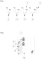
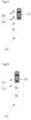
- Figure 1 shows a representation transmit pulses 2 and the receive windows.
- a large number of transmit pulses are sent and the receive windows adjusted or sweptin relation to the transmit pulse.
- the receive window timing shown by a, b, c and a (3, 4, 5, and 6 respectively).
- the change in the receive window timing with respect to the transmit pulse is shown with 3, 4, 5, and 6 of different magnitudes.
- FIG. 2 shows as example deployment of a directional sensor 30 according to the present invention (referred to hereinafter as "sensor”) in a roadside parking or moving vehicle application.
- Element 10 denotes a parking lane and 8 and 9 are sensor locations.
- Element 7 shows a representation of a bubble in the zone of interest. It will be appreciated that the directional sensor 30 of the present invention id provided for the purposes of detecting the presence of a vehicle or an object within a zone of interest on a roadway or in a parking space.
- FIG. 3 shows the ability of the sensor 30 to be mounted differently thus adapting to different geometries and installation requirements.
- Element 11 shows a pole mount, where the sensor 30 is mounted on a pole. The pole may be shared with parking meter or other street infrastructure.
- Element 12 denotes the sensor 30 mounted on a curb face or a curb top.
- Element 13 shows the sensor 30 embedded under the surface. This type of mounting can also be used when the bubble is directed at an angle.
- Figure 4 shows the sensor 30 integrated with wireless communications in any of the exemplary locations, 14, 15, and 16, communicating via a gateway or repeater 17, or via cellular network, represented by a tower 18.
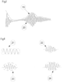
- a transmit pulse train is employed that includes a brief burst of a carrier wave, not more than 6 nanoseconds, but more typically 1-3 nanoseconds effective window width. While ideally this transmit burst may have the carrier wave at full amplitude instantaneously and have a rectangular envelope, in practice, the carrier wave envelope may take a triangular, trapezoidal, or another shape (for example, 23). See Figures 5 and 6 for examples of these different wave envelopes. Specifically, Figure 5 shows an illustration of a video output 20 if receive windows timing is continually swept in relation to the transmit for a fixed object and its envelope 19. Figure 6 shows examples of transmit bursts. Element 21 shows an burst with a rectangular envelope, and elements 22, 23, and 24 show triangular, sinusoidal, and other envelope shapes.
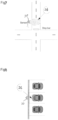
- Figure 7 shows an example location of the sensor 30 on top of a pole with a bubble 26 that overlaps an area immediately upstream of an intersection stop bar.
- Figure 8 shows the sensor 30 mounted adjacent to a parking space with the bubble 26 that is contained within a parking space being monitored.
- Figure 9 shows a parking space monitoring application wherein the sensor 30 (with the bubble 26) is positioned to detect the change in ranging distance as the vehicle is approaching or receding.
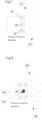
- Figures 10 and 11 illustrate profiles of data points obtained by successive ranging samples by elements 27 and 28 for a vehicle entry and exit event respectively.
- a very short transmit burst of the order of a few nanoseconds will occupy a very large portion of the radio spectrum.
- the transmit power levels need to be extremely low. This typically means that the received energy from just one or several bursts is not sufficient to make a reliable determination due to low signal to noise ratios.
- a large number of samples which may be in the thousands to over a hundred thousand samples or more need to be integrated. This needs to be accomplished within a reasonable measurement time.
- the duty cycle of the device needs to be adjusted to maximize the signal to noise ratio while still being a low duty cycle device.
- the receive window timing can be continuously swept in relation to the transmit pulse (see elements 3, 4, 5, 6 in FIG. 1 ) in order to generate a modulated video waveform with a fixed or adjustable sweep rate.
- Precise and repetitive control over the receive window's timing in relation to the transmit pulse is critical and can either be achieved by using the transmit burst's timing as a reference or using precision clocking circuitry.
- an adjustable receive window so as to be able to control the receive window to a desired range of interest and adjust the integration period for a particular range window is an advantage.
- a long receive window of the order of 10-20 ns can be employed just to scan if there is any received signal within this window and when a signal is found, the receive window can be further narrowed down to more precisely range the target vehicle.
- the advantage of this technique is that it will shorten the duration of the sensor active time when the space is vacant or there is no change in state, which will be the vast majority of the time, and hence will enable the sensor operation with significantly lower power consumption and is one of the disclosed adaptations that will help a longer battery life.
- a software controlled intelligent sensor to range only a narrow window of interest or selected discrete time ranges. This will enable the sensor to detect a narrower set of ranges in turn reducing the amount of time the sensor is active and reducing power consumption.
- a two or three dimensional bubble can be defined and the sensor can only be ranging at the edges of the bubble to detect if there is any vehicle entering the bubble; or if a vehicle is parked, as an example, 3 feet distance from the sensor, the sensor can normally range only around that previously measured vehicle distance and only upon a change in status, the sensor can range other ranges.
- the adjustable range capability can be used by software control to integrate selected range windows over longer or shorter periods of time to provide higher or lower signal to noise ratios. For example, in a noisy environment, if potential reflections are seen at a given range, but the object reflections do not clearly differentiate form the noise, the software can hover over that and adjacent range windows for longer periods of time and get a less noisier signal in order to make a determination of the object's presence and range.
- Figure 12 shows an example implementation wherein the time window of the receive window with respect to the transmit is fixed and in which the receive may be larger than the transmit pulse duration; phase variation in the reflected signal relative to the transmit pulse caused by the target's movement can be used to measure vehicle speed and also a corroborative evidence of a vehicle movement event. For example, this can be used to definitively exclude reflected signals from stationery targets.
- Figure 13 shows a block diagram illustration of a wired connection between a parking meter and the sensor 30. The sensor 30 may be attached to the meter or may be a modular detachable part. Element 29 represents a wired connection such as through discrete wires or a cable.
- Figure 14 shows a configuration in which the sensor 30 is embedded within a parking meter, access control device, or any other device that can be active or passive, including a parking space marking sign or a communications device.
- Figure 15 shows a plurality of the sensors 30 (in locations 31 and 32) that are wirelessly coupled to a plurality of network elements such as gateways, cellular towers, parking meters, access control devices, imaging devices, and to remote servers and databases.
- Figure 16 shows an example in which the transmit pulses are frequency modulated for the purposes of using an overlapping or fixed receive window with respect to the transmit or communicating low data rate information to or from an in-vehicle device.
- the integrator output can be digitized for many applications.
- the integrator output can be treated as an analog input voltage into an analog to digital converter and digitized.
- a modulated video waveform is generated with the envelope containing the object signature.
- the digitized signal can then be evaluated via software or hardware to see if it meets the criteria of an object signature and to extract presence and range information from the digitized signal.
- the center of the object profile or it is beginning or another point can be used for range determination.
- a one-bit digitizer can be used comprising of a comparator and indicate whether the integrator output exceeds a certain threshold level when sampling a desired range window.
- the circuitry for digitalization and evaluation can employ components such as, but not limited to, microcontrollers, analog to digital converter integrated circuits, field programmable gate arrays and other programmable logic devices, analog comparators and operational amplifiers, or simple active or passive components.
- Envelope information can be generated using a demodulator, low pass filter circuit or similar or by a variety of software algorithms based on filtering, peak detection or other techniques.
- This calls for special techniques to digitize the decay and comparing the decay to known profiles using profile matching or curve fitting techniques in software and determining the variance from a predefined decay model in order to extract object signatures from said integrator output.
- a differential technique may also be employed here by comparing the object profile with a simulated free space profile.
- the free space simulation can be accomplished using an absorber material that ensures there is no reflected signal. This can be accomplished by mechanically inserting an absorber material in the radiative path, but is more easily accomplished using an additional antenna element that may be coupled with an additional transmitting element.
- Drift in integrator output for example, can be detected by computing the average of the sample, detecting flat regions of the integrator response and comparing with previous measurements, or using a known range window that is guaranteed not to have an object present.
- Drift in integrator output for example, can be detected by computing the average of the sample, detecting flat regions of the integrator response and comparing with previous measurements, or using a known range window that is guaranteed not to have an object present.
- a parking space detection application for example, it is often not possible to clear out the parking space when installing, testing, or performing maintenance on a sensor.
- an RF or Infrared absorbing medium depending on the type of sensor, to simulate a no target object condition.
- a plurality of RF stages and antenna elements that can be switched can be used and an RF absorbing medium can block all radiation from one of the antenna elements.
- a device When switched to this element, a device can simulate a free space condition and thereby serve as a calibration reference.
- a material that is a known dielectric can be used to fill the spaces inside or just outside the antenna to help shape the antenna beam width to be optimal for the application.
- Such "beamforming" techniques allow us to use smaller antennas and shape the antenna field of view to best match the spatial area of interest and will help in achieving a narrow, defined spatial zone of interest.Also a plurality of antenna elements in combination with one or a plurality of RF stages may be used in an arrangement where some of them are may be switched to be able to steer the antenna.
- two adjacent spaces are being monitored by a sensor, that may be accomplished using two antenna elements that are switched based upon the desired space to monitor; or five antenna elements can be used to detecting 5 sub-zones across two parking spaces can help identify a variety of conditions, such as overlapped parking, bad parking situations, etc. This technique is especially useful when detecting vehicles in unmarked parking spaces.
- Clutter around the transmitter is a major source of error.
- Many sources can contribute to clutter including cables and wires around the sensor, the sensor housing, nearby objects that may get moved into the bubble but do not by themselves make the space being monitored unusable for the targets of interest.
- the sensor will be able to detect a permanent changed condition and ignore the clutter and get object signatures in relation to the clutter.
- This approach will provide some mitigation against clutter.
- Software algorithms and heuristics may be employed to determine which changes in returned signal profiles represent clutter and which changes represent the intended target and it is important in some cases to separate the two. Such determination can be done by using data related to strength of the reflected signal, the duration and persistence of the object, the distance from the sensor, etc.
- a stationery object it is important to distinguish between a stationery object from transient objects that are slow moving. For example, in a parking occupancy detection application, it may be desirable to count only automobiles that are fully parked and ignore sensor activations from persons walking across the spaces or shopping carts being moved across. Successive profiles from the sensor may be compared to ensure that the object signature is present and consistent for a period of time and classify the target as stationery or transient and apply suitable business rules.
- Apriori knowledge about expected probability of an object state change can be used in some cases to dynamically adjust the interval between data samples as a way of reducing battery life. For example, in a parking application, if the peak hours or high turnover hours for parking are known beforehand the sensing in those hours can be more frequent than others. At night time or during unregulated parking hours, when the data is less important, the samples can be stopped or taken at a reduced frequency. In some cases, this data can be self-generated at the sensor by analyzing historical patterns thus making the sensor self-adaptive.
- various software filters are employed in conjunction with the digitization of the video or the envelope signal.
- the video waveform's signal to noise ratio can be enhanced by a narrow bandpass filter and further low pass filtering or peak detection techniques can generate a low noise envelope waveform that contains information about the object profile.
- Such filtering can be performed with in time domain or in frequency domain. It should be noted that the filtering and envelope detection can be generated using hardware techniques as well. If the envelope signal is digitized or computed by software filters, it can also be further filtered using low pass or bandpass filters to reduce noise and obtain the object signature.
- determining the speed and direction of travel of the target object within the detection zone is important. This can be accomplished using multiple successive range measurements to discern whether the object is moving closer to or away from the sensor. This can be used very effectively in a parking monitoring situation to determine whether a vehicle is arriving at a space or leaving the space.
- the multiple successive range measurements combine to form of profile of the object's movement within the area of interest.
- This information can be communicated to a remote system using wired or wireless means and be used as further evidence of the object's movement.
- the additional information can be used as corroborative evidence in an administrative adjudication process or in a court of law.
- this method can be used to determine their direction of travel. This is also useful in situations where there is travel in more than one direction within the area of interest and only objects traveling in some of those directions are being monitored. For example, in an automated gate operation application, vehicles coming in towards the gate need to be identified separately from those moving away from the gate.
- the practical installation of the sensors imposes many challenges on the design. Places where the sensors are mounted such as roadways, walkways, etc. differ in construction materials, physical geometry and available mounting locations and other site specific considerations such as drainage, other uses, etc. It is important that the sensor design is flexible so as to be able to work at a particular site.
- the sensor may interface using wired or wireless means to other devices, such as parking meters, cameras, or gate control devices.
- a sensor that can be configured for various mounting locations would be highly desirable. This can be accomplished by means of separate enclosures, optimal direction of the antenna, and software configurations such that the detected object and clutter profiles are appropriate for the particular mounting arrangement.
- Figure 17 shows a sensor with a plurality of radiating elements 34, each radiating preferentially in a different direction so as to cover multiple zones of interest 33 or multiple regions within a zone of interest.
- Figure 18 shows a sensor configuration with a plurality of radiating elements 34, at least one of which has a radio frequency absorber material used for the purposed of calibrating the sensor.
- Figure 19 shows a vehicle 42 with an in-vehicle device within range of the sensor 30 to enable one-way or two-way communication.
- Figure 20 shows some of possible locations 38 for locating the in-vehicle device which include inside the vehicle chassis or outside near the front or rear of the vehicle 42.
- Figure 21 shows a plurality of the sensors 30 deployed close to each other with some of the bubbles 26 overlapping used in an unmarked parking application.
- Figure 22 shows a subterranean deployment of the sensors 30, each with a plurality of radiating elements positioned to detect occupancy and vehicle movement with apriori expectation of the vehicle's position. A plurality of the sensors 30 so deployed could cover the unmarked set of parking spaces.
- the directional sensor 30 for the purposes of detecting the presence of a vehicle or an object within a zone of interest on a roadway or in a parking space, according to the present invention, is schematically shown in Figure 23 and comprises:
- An exemplary schematic diagram of the sensor 30, shown in Figure 23 comprises a directional antenna 43 and a core timing generator 44 capable of generating sharp pulses with rise and fall times less than about 3 ns each and small pulse widths, typically less than 10 ns.
- the timing generator 44 may in turn be controlled or synchronized via a digital signal controller (or a microprocessor) 46.
- the core timing generator 44 may use an internal reference oscillator.
- the timing generator 44 controls the transmit and receive windows and their relative timing and depending on the embodiment, provides sweep, fixed, or discrete or arbitrarily adjustable capabilities.
- the sensor 30 further comprises a Mixer and Regenerative receiver 48 that represents an RF block including an RF oscillator tuned to a desired center frequency, a low noise amplifier, to amplify incoming reflected signals, a mixer/detector that can use regenerative techniques to generate a low frequency voltage that is a function of the reflected RF and amplified by the low noise amplifier.
- the low frequency voltage or current is further filtered through analog signal conditioning means 50.
- a digitizer 52 can be a single bit digitizer using a comparator or an analog-to-digital converter (ADC) circuit.
- the ADC 52 can be integral to a microcontroller or a digital signal controller or be a part of a circuit block on its own.
- the digitized signals can be further filtered, conditioned and processed through digital filtering/processing means 54 and software means 56.
- digital filtering/processing means 54 and software means 56 Various business rules and heuristics such as for reconfirmation checks, vehicle based rules, and others are executed through the software means 56.
- a power management and control block 58 is used to regulate one or more voltages required by the various parts of the circuit as well as to turn off power to the parts of the circuits in idle mode when they are not required, including in-between samples.
- the sensor output can be a data stream, or a digital or analog indication of vehicle presence or absence.
- This signal can be electrically coupled to another device including but not limited to parking meters, cameras, or gates, or can be coupled to a communication device such as a wireless modem or repeater.
- the information from the sensor including presence detection, range, direction, and profiles, can be sent to remote server for storage and further processing.
- a figure of merit related to the confidence level of the object detection and measurement can be calculated using one or more of the data available in the sensor, including the returned signal strength, consistency in readings in multiple readings, distance of object detected, signal to noise ratio calculated in the device.
- the calculated confidence level can be transmitted to a remote server along with the detection and measurement results and used by an end system such as an enforcement camera, parking meter, or an adjudication process.
- the receive window is kept constant with respect to the transmit during a part of or the whole measurement duration.
- a phase variation of the reflected RF is caused by the movement of the vehicle.
- This phase variation is sampled using analog or digital means and is used to compute the velocity of the vehicle.
- this information can be used as corroborative data to definitely establish a vehicle ingress or an egress event in an administrative adjudication process or in a court of law.
- the receive window may be adjusted to overlap with the transmit or a single window may be used for both receive and transmit with a suitable pulse width.
- This mode is particularly useful for detecting objects at very close range, for example, within 2 feet from the sensor.
- a plurality of RF stages and antenna elements can be used in a switched manner such that the RF path to the object traverses a plurality of lengths and if an object is present, at least of the lengths will result in a suitable phase difference between the reflected and the transmitted pulses to enable detection using a regenerative circuit or other means.
- the sensors are typically deployed as a network of sensors covering a plurality of parking spaces or road lanes.
- the wireless or wired communication means electrically coupled to the sensor can be considered as a part of the sensor network communicating to one or more remote servers and databases.
- the sensors may contain baseline profiles that are a function of the ranging distance, temperature, the integration time, or other parameters available from the sensor. Such profiles may use a combination of constant pre-determined data and data derived from the sensor either one time prior to installation or dynamically through a processor means.
- the sensor may be programmed with distances to range, time intervals that correspond to ranging distances, or geometrical properties of the zone of interest.
- the software means in the sensor can be used to derive pulse timing information or sweep rate information from the programmed data and this may further be used to control the sensor operation in the desired mode of operation.
- the programmable parts of the sensor and its configuration, including profiles, zone information, bubble and ranging information, sensitivity and threshold values, and the software executable code and its configurable elements can all be wirelessly downloaded using an appropriate protocol from a remote server. Such wireless downloads can be initiated by the server when the wireless module electrically coupled to the sensor is active. Such downloads may also be initiated by the processor means electrically coupled to the sensor querying the server for suitable downloads. For example, the sensor may be programmed to query the server once a day to check for any updates of executable or configuration elements and upon server response commence the download protocol.
- the sensor processor means may further contain a hardware or software watchdog to detect software or hardware malfunctions and automatically reset itself.
- a backup copy of an older or proven executable and configuration elements may be stored in persistent storage coupled to the processor means and in case of any malfunctions, the processor means may be programmed to try the backup copy.
- the low power features and battery operation in the present invention lend the sensor to be permanently installed in the road pavement or in the curb.
- the directional nature of the sensor enables us to configure the sensor for a wide range of geometries, and to locate the sensor on the curb or on a meter pole, outside the zone of interest.
- the ability to deploy the sensor based on the site characteristics is of great value in operating the sensor.
- the sensor may be programmed to send its diagnostic data periodically to a remote server using the wired or wireless communication means that is coupled to the processor means. Such information may be used to reconcile the sensing data and monitor the health of the sensor.
- Example data elements that can be sent for this purpose include occupancy time or ratio, counts of vehicle entry and exit events, battery voltage, count of samples taken, sensor active times, signal strength or quality metrics of the wireless link and other data available at the sensor.
- the sensor signals or data communicated through the wired or wireless means can be used by a parking meter to provide free time or to remove time from the meter or to provide information for enforcement personnel. For example, when a vehicle enters a parking space near a retail establishment, it may be desirable to provide s set amount of free time, say 15 minutes and the patron can be allowed to pay a meter to add to that.
- the data or signals it communicates using wired or wireless means can update the meter time. This can be accomplished whether the sensor first communicates to a remote server via a wireless network, including any gateway components, or the sensor send the signals or data to a parking meter using wireless or wired means.
- the senor can also act as a transponder to communicate with in-vehicle devices or handheld devices of maintenance and enforcement personnel.
- Modulation techniques to modulate a stream of pulses are well known, including pulse position modulation, pulse width modulation, phase modulation, frequency modulation, etc.
- the sensor pulses can be modulated to transmit information indicating the sensor operation or other data such as the lane number, space number and enforcement hours and tariff to in-vehicle or handheld devices.
- the senor can further be wirelessly coupled with an in-vehicle device capable of transmitting back to the sensor pertinent information, such as vehicle type, a unique identification of the vehicle, or classification of the vehicle.
- the in-vehicle device may be mounted in the interior or exterior of the vehicle chassis and may have a plurality of antennas. Alternatively, a plurality of in-vehicle devices may be used to cover the front and back of a vehicle. Since in some parking spaces, vehicles can park either in a front-in or a back-in configuration, a single in-vehicle device with antenna may not be sufficient.
- the in-vehicle device can use an RF amplifier to amplify the transmitted pulses and at least one fixed or programmable delay element and retransmit the amplified RF.
- This technique enables mirroring the incoming RF from the sensor and simulates a target at various ranges.
- the received profile from such a delayed mirror transmission can be easily distinguished from a physical target by its profile as well as the specific time slots that the in-vehicle device transmits.
- the in-vehicle device may transmit a code at specific ranging intervals, that will form a unique signature of an in-vehicle device.
- the code can contain a specific identification of the device that indicates unique vehicle identification, vehicle class, etc.
- the in-vehicle device can have a dynamically programmable delay code to transmit bits of data back to the sensor across multiple time sequences. This method will enable a longer code to be transmitted to the sensor.
- the senor can adjust the receive window to prevent an unfavorable fixed phase between the return signal and the transmit such that they cancel each other and prevent detection.
- the in-vehicle device may contain circuitry or logic to alter the delay to avoid this issue.
- the identification of the vehicle can be used by devices that are coupled with the sensor or a sensor network to grant preferential or differential treatment to the vehicle or to apply business or enforcement rules.
- This can be in the form of a gate access, lane access, discount schemes in a toll lane or a parking application, or to apply different business rules based on the vehicle identification or vehicle class received.
- the data can also be encrypted between the in-vehicle device and the sensor to prevent tampering.
- the exchange of information between the sensor and an in-vehicle device may be packaged as or may conform to a communications protocol.
- the senor can have a plurality of antenna elements with either a single RF stage or a plurality of RF stages.
- This capability also serves multiple purposes. For example, in a parking situation, two spaces may be covered by a single sensor. In another example, two zones covering the two edges of a parking space and another covering the middle may be used. If a vehicle is parked improperly in the space, two of the three zones will be occupied. If two adjacent vehicles are parked too close to the space under detection, the two edges will be occupied and the middle will be vacant. In a roadway configuration, a similar technique may be used to accurately determine the lane of travel. There are many applications where the parking spaces are unmarked. In these situations, it is not possible to predict where a vehicle will park in relation to the sensor. The available parking surface can be sampled as multiple smaller zones with one or more sensors and the resulting data can accurately determine the occupancy status and where a vehicle is located.
- the senor is used as a low power monitoring device in a roadway or an entry way.
- the sensor detects a vehicle or an object it is used to power on or wake up one or more additional devices, such as radar, Lidar, imagers, physical access control devices such as gates or barriers, electronic access controls, and communication devices.
- additional devices such as radar, Lidar, imagers, physical access control devices such as gates or barriers, electronic access controls, and communication devices.
- This is very useful in a battery powered application, such as portable traffic counting, portable speed enforcement, or surveillance application on a roadway or an entryway.
- the processor means, software means, timing and digital control circuitry, analog filters and processing circuitry, RF circuitry and antenna elements and other functional modules can reside in one or more boards that may be directly connected or interlinked through cables and connectors.
- the present invention provides a method of detecting change in occupancy state over a defined zone of interest on a roadway or parking space by computing the distance in 2 or 3 spatial dimensions from a directional ranging sensor to each boundary point of the zone of interest and adjusting the range monitoring parameters to monitor at or near the boundary distances to quickly detect when any vehicle enters the zone boundary, wherein the distance computation to the boundary may be manually set in hardware, preset in software, or dynamically computed in software logic.
- the present invention further provides a method of programming a directional ranging sensor used to detect the occupancy of a zone of interest in a roadway or parking space with programmable parameters such as location of sensor, width of traffic lane or parking space, that correspond to the geometric properties of the roadway zone of interest or parking space and the sensor programatically computing the monitoring parameters for optimal detection.
- the present invention provides a method of using a roadway or parking space sensor that modulates the transmit pulses of the sensor with additional information, such as lane number, maximum speed, space number, hours of operation, maximum duration of stay, or other pertinent information.
- Theinvention further defines the step of using any of pulse position modulation, phase modulation, frequency modulation, pulse width modulation or similar techniques.
- an in-vehicle device is capable of receiving the transmissions and sending a time-coded signal to the sensor that simulates range information is used with the in-vehicle device locking phase and frequency with the sensor transmission.
- the in-vehicle device transmits a unique vehicle identification data to the sensor.
- the sensor transmits information back to the in-vehicle device that is all or in part derived from all or a portion of the vehicle identification data obtained from the in-vehicle device. Additionally, at least one of the sensor transmission and the transmission from the in-vehicle device may be encrypted for security purposes.
- the unique vehicle identification is used to automatically provide roadway or parking services such as preferential access, permitted access, discounts, or other services. Additionally, the unique vehicle identification is used to detect scofflaw, stolen vehicles, or other vehicles of interest.
- the sensor transmission rate may be increased when a vehicle ingress event is detected to receive the information from the in-vehicle device.
- the in-vehicle device may incudes a low-noise radio frequency front-end amplifier and at least one delay circuit.
- a plurality of sensors and a plurality of in-vehicle devices may have communications compatibility in order for a given sensor to communicate with any of the vehicles with such capability.
- the in-vehicle device may include two or more antenna elements to cover the front and back of a vehicle.
- the plurality of in-vehicle devices may be used within a vehicle and they share all or a part of their unique identification number in order to determine that they belong to the same vehicle.
- a method of using a roadway or parking space sensor that combines or colocates the sensor with a radio frequency transmission device to transmit additional information, such as lane number, maximum speed, space number, hours of operation, maximum duration of stay, sensor operational status, or other pertinent information.
- the invention provides a method of using a directional, radio frequency time of flight sensor for the purposes of detection of the motion or the presence or absence of an automobile on a zone of interest on a roadway or in a parking space that includes a plurality of antenna elements, aligned in a plurality of directions, with the ability to switch between the elements to detect multiple zones of interest or multiple portions of a given zone of interest.
- the invention further includes selectively giving more weight to some zones or portions of a zone as detected by the plurality of antenna elements.
- the plurality of antenna elements may be provided with an RF absorber element to be used as a calibration reference.
- a software means may be used to compute the difference between the calibration reference and the measured profile of a target object in order to determine the presence and range of the target object.
- the sensor may contain any combination of a processor means, a software means, timing means, digital or analog filter means, and power management means where in each of these functions may reside on a plurality of circuit boards that are electrically coupled using connectors and cable means.
- a plurality of sensors may be deployed in unmarked parking spaces with a separation less than one car length in order to detect vehicles parked in unmarked spaces.
- the plurality of sensors each with a plurality of antenna elements may be deployed in unmarked parking spaces such that the combines zones cover the full area of parking spaces and the software means is used to discriminate vehicle position and occupancy status.
- the sensor is operated by at least one of battery power or solar power.
- the sensor may be embedded permanently within the roadsurface or curb or attached permanently to the curb.
- the sensor may be programmed to use variable sample rates based on estimated frequency of activity in the zone of interest, speed of movement within the zone of interest, or time of day.
- the sensor can be programmed to send diagnostic data to a remote server or meter periodically.
- the occupancy information from the sensors is used to detect lane use or parking violations and transmitted wirelessly to any field devices including, field enforcement aids, or dynamic street signage.
- the processing means maybe coupled with a failure recovery mechanisms including hardware or software watchdog mechanism to detect device failures and backup copies of executable code and configuration elements in persistent storage.
- a failure recovery mechanisms including hardware or software watchdog mechanism to detect device failures and backup copies of executable code and configuration elements in persistent storage.
- Successive profiles may be obtained using a set of ranging samples are compared for a period of time to determine whether the target object detected is stationery or a transient object.
- Figure 24 shows exemplary pulses used for the transmit pulse and the local oscillator pulse used in a receiver local oscillator corresponding to the receive window; the timings indicated are for example purposes only, while Figure 25 shows an exemplary spectrum of emission generated by a short pulse.
- Figure 25 shows an example schematic of the timing circuitry using a clock edge synchronization and a Pulse Width Modulation generator with two channels.
- the first channel is used with an adjustable delay to generate the transmit pulse of fixed or adjustable width.
- the second channel has an adjustable delay in relation to the same reference clock edge and has an adjustable pulse width.
- the two pulses may be added together to generate the transmit and receive windows control for the RF stages.
- Figure 26 shows a schematic of a timing generator to generate the transmit pulses and synchronize the receive windows with respect to the transmit window.
- Figure 26 shows an exemplary discrete digital timing generator with a discrete receive window width that is digitally controlled by a microprocessor.
- This implementation incorporates a reference oscillator to serve as the clock source, a fixed first pulse to for the transmit pulse and selectable delays that can be selected by a processor means and combining the two pulses to form a single pulse stream of transmit and receive pulses.
- Figure 27 shows an example discrete digital timing generator with a discrete receive window timings that are digitally controlled by a microprocessor. Specifically, Figure 27 shows an exemplary digitally controlled timing generator controlled by a digital signal controller. The transmit and the receive pulses are generated by the digital signal controller and use programmable pulse widths and timings.
- Figure 28 shows an example of a digitally controlled timing generator controlled by a digital signal controller
- Figure 29 shows an example of an analog timing generator that can be used with both the base frequency as well as the reference voltages controlling the pulse widths are set by a microprocessor
- Figure 28 shows an exemplary analog timing generator that can be used with both the base frequency as well as the reference voltages controlling the pulse widths are set by a microprocessor through an analog-to-digital converter that may be integrated within the microprocessor or be an external component.
- the first comparator generates an edge with fast slope to serve as a timing reference.
- the reference voltages set at the second and third comparators determine the time delay in their respective outputs relative to the first comparator output. The difference in time delays realized through the logic gate enables controlled and narrow pulse widths.
- the sensor unit that detects a characteristic change (e.g., of frequency and/or amplitude) of the signals that it processes.
- a change of one or more signal characteristics is associated with a change in status as to whether a vehicle is present or not.
- the sensor unit may take several readings per second. In one embodiment of the sensor unit, each new reading of the sensor unit is compared with the previous reading of the sensor unit.
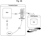
- the sensor 30 when the sensor 30 detects a change, relative to a previous reading, of one or more signal characteristics (associated with a change of a vehicle being present to a vehicle being not present, or from a vehicle being not present to a vehicle being present), the sensor data is formatted, and the sensor data that is associated with the current status (of a vehicle being present or not) is transmitted from the sensor unit to either the payment system (e.g., a parking meter) or a remote server, as described further below.
- Figures 38-40 also show that the data associated with a vehicle being present (or absent) are transmitted from the sensor unit to either the payment system (e.g., a parking meter) or a remote server.
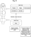
- Figures 41 and 42 show how the sensor circuit and the meter circuit are separate circuits, and not two logical portions of a single circuit.
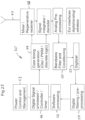
- Figure 31 shows a block diagram of the operation of a payment system (parking meter).
- the sensor unit when the sensor unit detects a change in status from a parking space being vacant to being occupied, the sensor unit will zero out any time that may be remaining on a parking meter from a vehicle that was previously occupying the parking space associated with that parking meter.
- the meter When the time on the meter elapses, the meter provides a visual indication that the parking space is unpaid and unoccupied.
- the payment system provides the visual indication apart from the sensor unit which, as described above, only detects a change in status that is associated with a change of a vehicle being present to a vehicle being not present, or from vehicle being not present to a vehicle being present.
- the presence indication and meter payment data are also transmitted from the parking meter to a server via the Internet.
- the sensor unit itself does not store data associated with a vehicle being present (or absent), and that the sensor unit is not designed for the purpose of storing the sensor data.
- the sensor unit is designed and intended to transmit the data indicative of a change in status to a parking meter (or to a server via the Internet in other embodiments) as fast as the sensor unit is able to do so.
- Figure 32 shows that the sensor unit may have a hardwired interconnect to the payment system (parking meter).
- Figure 32 also indicates that in an optional configuration, the sensor unit can be detached from the payment system, which is the case with multi-space meters.
- the payment system queries the sensor unit to obtain sensor data, and that the meter (and not the sensor unit) utilizes the sensor data to determine if there is a change in status that is associated with a change of a vehicle being present to a vehicle being not present, or from vehicle being not present to a vehicle being present.
- Figure 39 shows that the sensor unit can be attached to and communicate with the payment system (parking meter), and
- Figures 38 and 40 show that the sensor unit can be detached from the payment system and communicate with a server system.
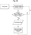
- Figure 33 shows a sensor unit that is detached from the payment system, and is positioned within or just below the surface of the street to detect the change in status that is associated with whether a vehicle is present or not.
- the sensor unit detects a change in status
- the sensor unit transmits the change of status wirelessly to the payment system or to a server by using a wireless interface to communicate with the server.
- the sensor unit initiates the transmission of data associated with a change of status that is associated with whether a vehicle being present to a vehicle being not present, or from vehicle being not present to a vehicle being present, upon detecting such a change, and that the data are transmitted to and stored in the parking meter or server.
- Figure 34 illustrates a block diagram of a sensor unit that is attached to the parking meter, and generally corresponds to Figure 32 .
- Figure 35 illustrates a block diagram of a sensor unit that is detached from the parking meter, and generally corresponds to Figure 33 .
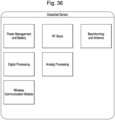
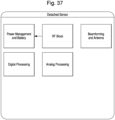
- FIGs 36 and 37 are respective sensor block diagrams of the detached sensor and the attached sensor embodiments.
- the detached sensor schematic differs from the attached sensor schematic ( Figure 37 ) in that the detached sensor schematic has a power management and battery block, whereas the attached sensor schematic only has a power management block.
- the attached sensor embodiment does not require a separate battery because it is powered by the same power source that is utilized by the parking meter.
- the detached sensor unit has a wireless communication module that allows the detached sensor unit to transmit data to the parking meter or the server, as indicated, for example, on Figure 33 .
- the following description of detached sensor configuration also applies to the attached sensor configuration.
- the detached sensor block diagram includes blocks or modules for power management and battery, RF (radio frequency), beamforming and antenna, digital processing, analog processing, and wireless communication functions.
- the power management and battery block is used to manage and control the power used by the detached sensor unit in order to extend the life of the battery used by the detached sensor unit. For example, the power management and battery block would ensure that the wireless communication module is not constantly transmitting to a parking meter or to the server, as such a transmission would shorten the life of the battery.
- the method according to the present invention uses a directional sensor for the purposes of detecting the presence of a vehicle or an object within a zone of interest on a roadway or in a parking space.
- This method according to the present invention comprises the following steps:
- At least one of the pulse repetition frequency, transmit pulse width, receive window duration, and the interval between the transmit and receive windows is adjustable using a digitally controlled circuit or under software control from a microprocessor.
- the receive window is adjusted by software control in order to dwell on a particular receive time slice region of interest so as to increase the signal to noise ratio of the received measurement.
- the receive window is also kept longer than the transmit pulse duration when the roadway or parking space being monitored is vacant and when an occupancy change is detected the receive window is made smaller to more precisely range the vehicle
- the interval between the transmit and receive windows is continuously adjusted using an analog or digital hardware sweep circuit or under software control.
- the software is programmed to adjust the interval between the transmit and receive windows to a programatically determined zone of interest.
- the zone of interest is based on the expected region where a change in occupancy state will happen, including the previously measured distance of an occupying stationery vehicle, a programmed maximum distance if the detection zone was previously vacant, or a predicted zone of occupancy if a vehicle is moving.
- the receive window is adjusted by software control in order to dwell on a particular receive time slice region of interest so as to increase the signal to noise ratio of the received measurement.
- the senor is placed at one of (a) a location below the surface of the zone of interest, (b) a location above the surface and in contact with the zone of interest, (c) a location near the surface and adjacent to the zone of interest oriented to radiate preferentially towards the zone of interest, (d) a location on a raised fixture near the zone of interest oriented to radiate preferentially towards the zone of interest, (e) a location embedded within a parking meter or an access control device, and (f) a location embedded within a parking space number sign.
- the receive window is continuously swept at a fixed or adjustable rate with respect to the transmit window in order to generate a video waveform output and optimize the detection latency and signal to noise ratio, wherein the video waveform output is digitized using an analog to digital conversion process using a circuit that is electrically coupled to the receiver and integrator and the digitized output is suitably filtered and compared to a preset or dynamically computed threshold profiles in order to discern whether there is sufficient returned signal from an object in the field of view of the sensor.
- the transmit and receive windows are pulsed at a rate between 5 MHz and 50 MHz in order to optimize the signal to noise while ensuring compliance with regulatory limits. Also, when a change of state is determined from the returned signal, successive sets of samples are taken in quick succession to confirm or deny the first determination of change and a confidence level is computed based on the consistency in readings.
- the filter is one of a hardware filter electrically coupled to the receiver and integrator, and a software algorithm using digitized signals. Moreover, a software or hardware envelope detector is used to extract a lower frequency profile of the received signal from a generated video.
- the method according to the present invention can further comprise a mode in which the interval between the transmit and receive windows is kept fixed and the vehicle movement will result in a Doppler effect on the returned signal due to the phase shift of the returned signal in relation to the transmit and a phase coherent detection is performed returned signal phase varying in relation to the transmit pulse with vehicle movement and the resulting phase difference to combine destructively or constructively with the transmit pulse at the detector.
- Ranging and Doppler detection is used as corroborative data to increase the confidence of measurement, and the Doppler signal is further processed to determine whether a change in state event is an ingress or an egress event.
- change in occupancy state and any of the other data elements or available in the sensor on the roadway or parking space is communicated to an external host using wired or wireless means, wherein a plurality of sensors are communicating to at least one external host using wired or wireless means forming a network of sensors that communicate with the host for the purposes of data transmission from the sensors, and configuration, monitoring and control of the sensors.
- the transmit and receive windows are fully or partially overlapping in order to detect vehicles at very close distances and the transmit pulse frequency is varied by using one of (a) frequency modulating the transmit pulse (b) discrete frequency control of the transmit oscillator to generate at least two distinct frequencies and (c) incorporating a known amount of frequency noise or drift in the transmit oscillator.
- successive ranging samples are used to determine whether there is a gradual change in object range in order to discern whether a change in state event is an ingress or an egress event and a profile of the ingress or egress is captured by multiple ranging samples, wherein the profile obtained is transmitted to an external host using wired or wireless means for storage.
- the time of flight ranging is used as a low power monitoring device and the change of state determined from the received signal is used to wake one or more additional devices, such as a speed measurement device or an imaging device in order to manage the power consumption of those devices.
- a high dielectric material is used inside or near the antenna element to enable a narrow beamwidth in a small antenna package.
- the method of the present invention further comprises a baseline profile that includes the transmit burst, initial clutter around the sensor and integrator decay so as to discern the signatures of close-in objects whose signals are mixed in with the transmit burst, initial clutter, or the integrator decay.
- the method of the present invention further comprises a temperature compensation of the baseline profile, including for the initial clutter, integrator decay and noise thresholds.
Applications Claiming Priority (4)
| Application Number | Priority Date | Filing Date | Title |
|---|---|---|---|
| US201161549029P | 2011-10-19 | 2011-10-19 | |
| US201261638173P | 2012-04-25 | 2012-04-25 | |
| PCT/US2012/036615 WO2013058830A1 (en) | 2011-10-19 | 2012-05-04 | Directional speed and distance sensor |
| EP12726928.0A EP2769235B1 (de) | 2011-10-19 | 2012-05-04 | Gerichteter geschwindigkeits- und abstandssensor |
Related Parent Applications (1)
| Application Number | Title | Priority Date | Filing Date |
|---|---|---|---|
| EP12726928.0A Division EP2769235B1 (de) | 2011-10-19 | 2012-05-04 | Gerichteter geschwindigkeits- und abstandssensor |
Publications (1)
| Publication Number | Publication Date |
|---|---|
| EP4339645A2 true EP4339645A2 (de) | 2024-03-20 |
Family
ID=46246169
Family Applications (2)
| Application Number | Title | Priority Date | Filing Date |
|---|---|---|---|
| EP12726928.0A Active EP2769235B1 (de) | 2011-10-19 | 2012-05-04 | Gerichteter geschwindigkeits- und abstandssensor |
| EP23211786.1A Pending EP4339645A2 (de) | 2011-10-19 | 2012-05-04 | Richtungsgeschwindigkeits- und entfernungssensor |
Family Applications Before (1)
| Application Number | Title | Priority Date | Filing Date |
|---|---|---|---|
| EP12726928.0A Active EP2769235B1 (de) | 2011-10-19 | 2012-05-04 | Gerichteter geschwindigkeits- und abstandssensor |
Country Status (7)
| Country | Link |
|---|---|
| US (7) | US8878697B2 (de) |
| EP (2) | EP2769235B1 (de) |
| KR (1) | KR101528117B1 (de) |
| CN (3) | CN110441742A (de) |
| AU (1) | AU2012325362B2 (de) |
| HK (1) | HK1203092A1 (de) |
| WO (1) | WO2013058830A1 (de) |
Families Citing this family (114)
| Publication number | Priority date | Publication date | Assignee | Title |
|---|---|---|---|---|
| US8513832B2 (en) | 2007-03-30 | 2013-08-20 | Ips Group Inc. | Power supply unit |
| CA2745365C (en) | 2008-12-23 | 2013-01-08 | J.J. Mackay Canada Limited | Low power wireless parking meter and parking meter network |
| CA2773132C (en) | 2009-09-04 | 2015-11-03 | Ips Group Inc. | Location-aware advertising to parking location users |
| US8749403B2 (en) | 2009-09-04 | 2014-06-10 | Ips Group Inc. | Parking meter communications for remote payment with updated display |
| CA3178279A1 (en) | 2011-03-03 | 2012-09-03 | J.J. Mackay Canada Limited | Parking meter with contactless payment |
| US9127964B2 (en) | 2011-07-25 | 2015-09-08 | Ips Group Inc. | Low power vehicle detection |
| EP2769235B1 (de) * | 2011-10-19 | 2023-11-29 | Balu Subramanya | Gerichteter geschwindigkeits- und abstandssensor |
| CN104115197A (zh) * | 2011-12-05 | 2014-10-22 | 布莱特瓦维森有限公司 | 智能交通标志系统与方法 |
| US20140005961A1 (en) * | 2012-06-29 | 2014-01-02 | TCS International, Inc. | Occupancy sensing |
| US8686874B2 (en) | 2012-07-24 | 2014-04-01 | Sentry Protection Llc | Corner sensor assembly |
| US11004337B2 (en) | 2012-12-28 | 2021-05-11 | Balu Subramanya | Advanced parking management system |
| US9596901B1 (en) * | 2013-01-25 | 2017-03-21 | Kiomars Anvari | Helmet with wireless sensor using intelligent main shoulder pad |
| WO2014118872A1 (ja) * | 2013-01-29 | 2014-08-07 | 有限会社ラムロック映像技術研究所 | 監視システム |
| DE102013102683A1 (de) * | 2013-03-15 | 2014-09-18 | Jenoptik Robot Gmbh | Verfahren zur Erfassung von Verkehrsverstößen in einem Ampelbereich durch Heckanmessung mit einem Radargerät |
| US9696420B2 (en) * | 2013-04-09 | 2017-07-04 | Ford Global Technologies, Llc | Active park assist object detection |
| PL2804013T3 (pl) * | 2013-05-13 | 2015-10-30 | Kapsch Trafficcom Ag | Urządzenie do pomiaru położenia pojazdu albo jego powierzchni |
| PT2804014E (pt) * | 2013-05-13 | 2015-09-10 | Kapsch Trafficcom Ag | Dispositivo e método para determinar uma característica de um veículo |
| DE102013215208A1 (de) * | 2013-08-02 | 2015-02-05 | Ford Global Technologies, Llc | Verfahren und Vorrichtung zur Einparkunterstützung eines Fahrzeuges |
| EP2865575B1 (de) | 2013-10-22 | 2022-08-24 | Honda Research Institute Europe GmbH | Vertrauensschätzung für prädiktive Fahrerunterstützungssysteme auf Basis von Plausibilitätsregeln |
| EP2865576B1 (de) * | 2013-10-22 | 2018-07-04 | Honda Research Institute Europe GmbH | Zusammengesetzte Vertrauensschätzung für prädiktive Fahrerunterstützungssysteme |
| US9330568B2 (en) * | 2013-10-30 | 2016-05-03 | Xerox Corporation | Methods, systems and processor-readable media for parking occupancy detection utilizing laser scanning |
| DE102014208386A1 (de) * | 2014-05-06 | 2015-11-12 | Robert Bosch Gmbh | Verfahren und Vorrichtung zum Überwachen eines immobilen Raumbereichs |
| US10025890B2 (en) * | 2014-07-11 | 2018-07-17 | Advanced Testing Technologies, Inc. | Phase noise simulation model for pulse doppler radar target detection |
| US9463706B2 (en) | 2014-07-23 | 2016-10-11 | Ford Global Technologies, Llc | Infrared triangulation method for locating vehicles for hands-free electric vehicle charging |
| US9476968B2 (en) * | 2014-07-24 | 2016-10-25 | Rosemount Aerospace Inc. | System and method for monitoring optical subsystem performance in cloud LIDAR systems |
| USD749000S1 (en) | 2014-07-24 | 2016-02-09 | Ips Group Inc. | Radar enhanced parking meter |
| US9420620B2 (en) * | 2014-09-30 | 2016-08-16 | Honeywell International Inc. | Systems and methods for aircraft on-ground determination |
| US9508198B1 (en) | 2014-12-23 | 2016-11-29 | Ips Group Inc. | Meters and upgraded meter cover with sensor |
| CN106199738A (zh) * | 2015-02-15 | 2016-12-07 | 鲍星合 | 物体存在检测装置及方法 |
| DE102015202788A1 (de) * | 2015-02-17 | 2016-08-18 | Robert Bosch Gmbh | System und Verfahren zur Erkennung eines Belegungszustandes von Parkplätzen |
| GB201503855D0 (en) * | 2015-03-06 | 2015-04-22 | Q Free Asa | Vehicle detection |
| USD756807S1 (en) | 2015-03-18 | 2016-05-24 | Ips Group Inc. | Radar enhanced parking meter |
| USD756808S1 (en) | 2015-03-23 | 2016-05-24 | Ips Group Inc. | Radar enhanced parking meter |
| US10043307B2 (en) | 2015-04-17 | 2018-08-07 | General Electric Company | Monitoring parking rule violations |
| US10380430B2 (en) | 2015-04-17 | 2019-08-13 | Current Lighting Solutions, Llc | User interfaces for parking zone creation |
| DE102015211054B4 (de) * | 2015-06-16 | 2021-09-02 | Robert Bosch Gmbh | Steuerung eines Parkplatzsensors |
| DE102015211053B4 (de) * | 2015-06-16 | 2021-09-02 | Robert Bosch Gmbh | Steuerung eines Parkplatzsensors |
| CA2894350C (en) | 2015-06-16 | 2023-03-28 | J.J. Mackay Canada Limited | Coin chute with anti-fishing assembly |
| RU2602891C1 (ru) * | 2015-07-08 | 2016-11-20 | Борис Григорьевич Татарский | Радиолокационная система мониторинга открытых автомобильных стоянок и определения свободных мест для парковки автомобилей |
| USRE48566E1 (en) | 2015-07-15 | 2021-05-25 | J.J. Mackay Canada Limited | Parking meter |
| CN105162197B (zh) * | 2015-09-09 | 2018-06-15 | 北京无线电测量研究所 | 一种边界层风廓线雷达的供电系统及方法 |
| US10397546B2 (en) | 2015-09-30 | 2019-08-27 | Microsoft Technology Licensing, Llc | Range imaging |
| USD813059S1 (en) | 2016-02-24 | 2018-03-20 | J.J. Mackay Canada Limited | Parking meter |
| CN105891811A (zh) * | 2015-10-16 | 2016-08-24 | 乐卡汽车智能科技(北京)有限公司 | 车联网中的车辆距离确定方法和装置 |
| US11164452B2 (en) * | 2015-10-27 | 2021-11-02 | Municipal Parking Services, Inc. | Parking space detection method and system |
| ES2615164B1 (es) * | 2015-11-05 | 2018-03-28 | Ontech Security Sl | Sistema y método de seguridad para vehículos |
| CN105631400A (zh) * | 2015-11-25 | 2016-06-01 | 东莞酷派软件技术有限公司 | 信息处理方法、信息处理装置、智能模块和车载终端 |
| DE102015226443A1 (de) * | 2015-12-22 | 2017-06-22 | Robert Bosch Gmbh | Radarsensor, entsprechendes Betriebsverfahren und Fahrzeug |
| US10523923B2 (en) | 2015-12-28 | 2019-12-31 | Microsoft Technology Licensing, Llc | Synchronizing active illumination cameras |
| DE102016202608A1 (de) * | 2016-02-19 | 2017-08-24 | Siemens Aktiengesellschaft | Verkehrsüberwachungssystem mit einer Wellenleiteinrichtung zur Überwachung einer Verkehrsfläche |
| DE102016202936A1 (de) * | 2016-02-25 | 2017-08-31 | Robert Bosch Gmbh | Vorrichtung zum Ermitteln von Betriebsdaten für einen Radarsensor |
| US10299018B1 (en) * | 2016-02-29 | 2019-05-21 | Ips Group Inc. | Pole-mounted vehicle sensor |
| US10509121B2 (en) * | 2016-03-04 | 2019-12-17 | Uatc, Llc | Dynamic range setting for vehicular radars |
| US10462452B2 (en) | 2016-03-16 | 2019-10-29 | Microsoft Technology Licensing, Llc | Synchronizing active illumination cameras |
| DE102016107995A1 (de) * | 2016-04-29 | 2017-11-02 | Cleverciti Systems Gmbh | Parkplatzüberwachungssystem |
| KR102384875B1 (ko) * | 2016-05-11 | 2022-04-08 | 삼성전자주식회사 | 거리 센서의 칼리브레이션 방법, 장치 및 시스템 |
| TWI579578B (zh) * | 2016-05-30 | 2017-04-21 | 均利科技股份有限公司 | 停車位狀態感測系統與方法 |
| US10411716B2 (en) * | 2016-06-06 | 2019-09-10 | Richwave Technology Corp. | Subsampling motion detector for detecting motion of object under measurement |
| TW201800775A (zh) * | 2016-06-21 | 2018-01-01 | 安研科技股份有限公司 | 車輛變動判斷系統及其方法 |
| US10604120B2 (en) | 2016-07-07 | 2020-03-31 | Nio Usa, Inc. | Sensor cleaning devices and systems |
| CN107640090A (zh) * | 2016-07-22 | 2018-01-30 | 中兴通讯股份有限公司 | 一种行车安全控制方法及装置 |
| DE102016213982A1 (de) * | 2016-07-29 | 2018-02-01 | Robert Bosch Gmbh | Konzept zum Überwachen eines Parkplatzes für Kraftfahrzeuge |
| CN107784852B (zh) * | 2016-08-31 | 2021-03-30 | 奥迪股份公司 | 用于车辆的电子控制装置及方法 |
| US10317511B2 (en) * | 2016-11-15 | 2019-06-11 | Veoneer Us, Inc. | Systems and methods for synchronizing processor operations over a communications network |
| EP3543736A4 (de) * | 2016-11-21 | 2020-07-29 | LG Electronics Inc. -1- | Fahrzeugradarvorrichtung und fahrzeug |
| US10515390B2 (en) * | 2016-11-21 | 2019-12-24 | Nio Usa, Inc. | Method and system for data optimization |
| CA3046381A1 (en) * | 2016-12-09 | 2018-06-14 | Rumbo Mobile Inc. | System and method for monitoring occupancy at each of a plurality of locations |
| DE102017200706A1 (de) * | 2017-01-18 | 2018-07-19 | Robert Bosch Gmbh | Mehrfach unterabgetastetes Chirp-Sequence-Radar |
| DE102017201219A1 (de) * | 2017-01-26 | 2018-07-26 | Robert Bosch Gmbh | Verfahren und System zum Erkennen von Objekten anhand von Ultraschallsignalen |
| FR3062500A1 (fr) * | 2017-02-02 | 2018-08-03 | Valeo Systemes D'essuyage | Procede de suivi de l'utilisation d'un systeme d'essuyage d'un vehicule automobile |
| EP3896868A1 (de) * | 2017-03-28 | 2021-10-20 | QUALCOMM Incorporated | Bereichsbasierte getriebeparametereinstellung |
| US10386856B2 (en) * | 2017-06-29 | 2019-08-20 | Uber Technologies, Inc. | Autonomous vehicle collision mitigation systems and methods |
| US10065638B1 (en) | 2017-08-03 | 2018-09-04 | Uber Technologies, Inc. | Multi-model switching on a collision mitigation system |
| US10914110B2 (en) * | 2017-11-02 | 2021-02-09 | Magna Closures Inc. | Multifunction radar based detection system for a vehicle liftgate |
| CN108169755A (zh) * | 2017-12-14 | 2018-06-15 | 中国航空工业集团公司洛阳电光设备研究所 | 一种高精度远程激光测距机及测距方法 |
| CN108288391A (zh) * | 2018-01-31 | 2018-07-17 | 四川驿停车智慧科技有限公司 | 一种停车场出口车流量预警系统 |
| TW201935429A (zh) * | 2018-02-08 | 2019-09-01 | 和碩聯合科技股份有限公司 | 警示器及可移動載具組件 |
| EP3531167B1 (de) * | 2018-02-21 | 2021-04-07 | Ibeo Automotive Systems GmbH | Verfahren und vorrichtung zur optischen distanzmessung |
| EP3561958B1 (de) * | 2018-04-24 | 2023-10-18 | Fundacion Centro De Tecnologias De Interaccion Visual Y Comunicaciones Vicomtech | Verfahren zum ausrichten von reflektoren eines terahertz-kommunikationssystems |
| US10836762B2 (en) * | 2018-06-20 | 2020-11-17 | Quixotic Holdings LLC | Network-centric sensor coverage management |
| DE102018213940A1 (de) * | 2018-08-17 | 2020-02-20 | Robert Bosch Gmbh | Vorrichtung mit einer Sensoreinheit und einer Selbstkalibrierungsfunktion |
| JP2020057869A (ja) * | 2018-09-28 | 2020-04-09 | パナソニックi−PROセンシングソリューションズ株式会社 | 撮像装置 |
| CH715491A1 (de) * | 2018-10-23 | 2020-04-30 | Greatcom Ag | Überwachungssystem und Verfahren zum Erfassen von Verkehrsteilnehmern in einem Erfassungsbereich. |
| US10725175B2 (en) | 2018-10-30 | 2020-07-28 | United States Of America As Represented By The Secretary Of The Air Force | Method, apparatus and system for receiving waveform-diverse signals |
| US11693423B2 (en) * | 2018-12-19 | 2023-07-04 | Waymo Llc | Model for excluding vehicle from sensor field of view |
| CN109714703B (zh) * | 2018-12-24 | 2021-06-01 | 武汉长江通信产业集团股份有限公司 | 基于云平台的车载终端定位精度的测量方法、装置及系统 |
| CN109637185B (zh) * | 2018-12-28 | 2022-04-05 | 张明荣 | 一种充电桩车位管理方法与系统 |
| CN109541631A (zh) * | 2019-01-07 | 2019-03-29 | 杭州蓝芯科技有限公司 | 一种基于光飞行时间的大视场面阵探测雷达 |
| CN109572428A (zh) * | 2019-01-16 | 2019-04-05 | 谢宝建 | 一种新型车辆进出入厂区自动限速解决方案 |
| US11922756B2 (en) | 2019-01-30 | 2024-03-05 | J.J. Mackay Canada Limited | Parking meter having touchscreen display |
| CA3031936A1 (en) | 2019-01-30 | 2020-07-30 | J.J. Mackay Canada Limited | Spi keyboard module for a parking meter and a parking meter having an spi keyboard module |
| USD911857S1 (en) | 2019-02-20 | 2021-03-02 | Ips Group Inc. | Sensor enhanced parking meter |
| CN110308441A (zh) * | 2019-07-04 | 2019-10-08 | 唐山迪安自动化设备有限公司 | 退火炉内钢带位置测量传感器 |
| EP3888276B1 (de) * | 2019-08-30 | 2023-05-31 | Baidu.com Times Technology (Beijing) Co., Ltd. | Überprüfung der zeitsteuerung von sensoren in autonom fahrenden fahrzeugen |
| CN111323757B (zh) * | 2019-12-30 | 2022-04-05 | 北京海兰信数据科技股份有限公司 | 一种航海雷达目标检测方法及装置 |
| CN111047868B (zh) * | 2020-01-17 | 2020-12-11 | 深圳市戴升智能科技有限公司 | 道路车辆流量检测方法、装置、计算机设备及存储介质 |
| DE102020102851A1 (de) * | 2020-02-05 | 2021-08-05 | Dspace Digital Signal Processing And Control Engineering Gmbh | Prüfvorrichtung zum Test eines mit Ultraschallwellen arbeitenden Abstandssensors |
| US11194044B2 (en) | 2020-02-13 | 2021-12-07 | Tymphany Acoustic Technology (Huizhou) Co., Ltd. | Object movement detection based on ultrasonic sensor data analysis |
| CN111295025B (zh) * | 2020-03-07 | 2021-04-06 | 湖南正美光电科技有限公司 | 一种采用LoRa技术的节能型城市智慧路灯 |
| CN111653105B (zh) * | 2020-04-30 | 2022-03-15 | 南京理工大学 | 一种道路两侧基于无源被动技术的车辆测速方法及系统 |
| CN111580125B (zh) * | 2020-05-28 | 2022-09-09 | Oppo广东移动通信有限公司 | 飞行时间模组及其控制方法、电子设备 |
| CN111815962A (zh) * | 2020-07-08 | 2020-10-23 | 支付宝(杭州)信息技术有限公司 | 车辆身份的识别方法、装置、主设备和从设备 |
| US11550029B2 (en) * | 2020-07-16 | 2023-01-10 | Analog Devices International Unlimited Company | Delay calibration for a stepped frequency continuous wave digital signal chain |
| US11703563B2 (en) * | 2020-09-24 | 2023-07-18 | Integrated Device Technology, Inc. | Sliding window and DC offset correction technique for pulse doppler radar systems |
| USD1011933S1 (en) | 2020-10-01 | 2024-01-23 | Ips Group Inc. | Pole-mounted sensor |
| USD986084S1 (en) | 2020-10-01 | 2023-05-16 | Ips Group Inc. | Pole-mounted sensor |
| CN112242010B (zh) * | 2020-10-26 | 2022-06-28 | 厦门中卡科技股份有限公司 | 一种城市道路停车etc巡查车收费系统及收费方法 |
| USD996237S1 (en) | 2020-11-19 | 2023-08-22 | Ips Group Inc. | Sensor enhanced meter |
| USD959299S1 (en) | 2020-11-19 | 2022-08-02 | Ips Group Inc. | Meter cover |
| USD959298S1 (en) | 2020-11-19 | 2022-08-02 | Ips Group Inc. | Meter cover |
| USD986082S1 (en) | 2020-11-19 | 2023-05-16 | Ips Group Inc. | Sensor enhanced meter |
| USD959997S1 (en) | 2020-11-19 | 2022-08-09 | Ips Group Inc. | Meter cover |
| US20220319297A1 (en) * | 2021-04-02 | 2022-10-06 | United States Postal Service | Detecting an Obstruction to a Feature of a Building and Warning of the Obstruction |
| CN114018266B (zh) * | 2021-10-28 | 2023-11-17 | 北京信息科技大学 | 基于fpga和dsp的多串口通信导航计算装置 |
Family Cites Families (181)
| Publication number | Priority date | Publication date | Assignee | Title |
|---|---|---|---|---|
| US3126540A (en) | 1964-03-24 | Mixer | ||
| US2709252A (en) | 1948-08-20 | 1955-05-24 | Gilfillan Bros Inc | Multi-plane tracking in ground controlled approach system |
| US2921301A (en) | 1956-07-06 | 1960-01-12 | Parsons Co Ralph M | Distance measuring system |
| US3241106A (en) | 1960-05-09 | 1966-03-15 | Lab For Electronics Inc | Traffic actuated control apparatus |
| US3182312A (en) | 1962-01-11 | 1965-05-04 | Lab For Electronics Inc | Vehicle detection and counting system |
| US3174146A (en) | 1962-10-12 | 1965-03-16 | Bell Aerospace Corp | Automatic landing systems |
| US4227195A (en) | 1963-09-19 | 1980-10-07 | The United States Of America As Represented By The Secretary Of The Army | Fuze |
| FR1478429A (fr) | 1966-02-09 | 1967-04-28 | Automatisme Cie Gle | Procédé et dispositif de mesure de la concentration de la circulation automobile |
| US3626413A (en) | 1970-02-02 | 1971-12-07 | Howard C Zachmann | Traffic surveillance and control system |
| FR2202332B1 (de) | 1972-10-05 | 1979-02-09 | Labo Cent Telecommunicat | |
| US3976999A (en) | 1973-10-19 | 1976-08-24 | Vega Precision Laboratories, Inc. | Airborne target recognition system |
| US4190882A (en) | 1977-05-05 | 1980-02-26 | Hughes Aircraft Company | System for reducing the effects of power supply switching |
| US4167735A (en) | 1978-08-18 | 1979-09-11 | The United States Of America As Represented By The Secretary Of The Navy | Aircraft orientation determining means |
| US4620192A (en) | 1983-09-29 | 1986-10-28 | Raytheon Company | Continuous wave radar with ranging capability |
| JPS60122067A (ja) | 1983-12-02 | 1985-06-29 | Hitachi Ltd | 懸濁液処理装置 |
| JPH0135699Y2 (de) | 1986-02-20 | 1989-10-31 | ||
| JPS6435699A (en) | 1987-07-30 | 1989-02-06 | Omron Tateisi Electronics Co | On-road device |
| US4901083A (en) | 1988-06-20 | 1990-02-13 | Delco Electronics Corporation | Near obstacle detection system |
| US5189425A (en) | 1990-09-14 | 1993-02-23 | Dabbs John W T | Method and apparatus for monitoring vehicular traffic |
| US5075680A (en) | 1990-09-14 | 1991-12-24 | Dabbs John W T | Method and apparatus for monitoring vehicular traffic |
| US5274271A (en) | 1991-07-12 | 1993-12-28 | Regents Of The University Of California | Ultra-short pulse generator |
| CA2113454A1 (en) | 1992-05-18 | 1993-11-25 | Werner Sieprath | Process for monitoring a zone |
| US5471162A (en) | 1992-09-08 | 1995-11-28 | The Regents Of The University Of California | High speed transient sampler |
| US5337082A (en) | 1992-12-07 | 1994-08-09 | Whelen Technologies, Inc. | Traffic management system |
| US5774091A (en) | 1993-04-12 | 1998-06-30 | The Regents Of The University Of California | Short range micro-power impulse radar with high resolution swept range gate with damped transmit and receive cavities |
| US5767953A (en) | 1993-04-12 | 1998-06-16 | The Regents Of The University Of California | Light beam range finder |
| US5361070B1 (en) * | 1993-04-12 | 2000-05-16 | Univ California | Ultra-wideband radar motion sensor |
| US5345471A (en) | 1993-04-12 | 1994-09-06 | The Regents Of The University Of California | Ultra-wideband receiver |
| US5757320A (en) | 1993-04-12 | 1998-05-26 | The Regents Of The University Of California | Short range, ultra-wideband radar with high resolution swept range gate |
| US5519400A (en) | 1993-04-12 | 1996-05-21 | The Regents Of The University Of California | Phase coded, micro-power impulse radar motion sensor |
| US5457394A (en) | 1993-04-12 | 1995-10-10 | The Regents Of The University Of California | Impulse radar studfinder |
| US5517198A (en) | 1993-04-12 | 1996-05-14 | The Regents Of The University Of California | Ultra-wideband directional sampler |
| US5661490A (en) | 1993-04-12 | 1997-08-26 | The Regents Of The University Of California | Time-of-flight radio location system |
| US5510800A (en) | 1993-04-12 | 1996-04-23 | The Regents Of The University Of California | Time-of-flight radio location system |
| US5523760A (en) | 1993-04-12 | 1996-06-04 | The Regents Of The University Of California | Ultra-wideband receiver |
| US5374932A (en) | 1993-08-02 | 1994-12-20 | Massachusetts Institute Of Technology | Airport surface surveillance system |
| US5519618A (en) | 1993-08-02 | 1996-05-21 | Massachusetts Institute Of Technology | Airport surface safety logic |
| US5465094A (en) | 1994-01-14 | 1995-11-07 | The Regents Of The University Of California | Two terminal micropower radar sensor |
| CA2170737A1 (en) | 1994-02-07 | 1995-08-10 | Harold Ii Pace | Mobile location reporting apparatus and methods |
| US5804921A (en) | 1994-02-09 | 1998-09-08 | The Regents Of The University Of California | Soliton quenching NLTL impulse circuit with a pulse forming network at the output |
| US5422607A (en) | 1994-02-09 | 1995-06-06 | The Regents Of The University Of California | Linear phase compressive filter |
| US7359782B2 (en) * | 1994-05-23 | 2008-04-15 | Automotive Technologies International, Inc. | Vehicular impact reactive system and method |
| US5573012A (en) | 1994-08-09 | 1996-11-12 | The Regents Of The University Of California | Body monitoring and imaging apparatus and method |
| US5682164A (en) | 1994-09-06 | 1997-10-28 | The Regents Of The University Of California | Pulse homodyne field disturbance sensor |
| US5589838A (en) | 1994-09-06 | 1996-12-31 | The Regents Of The University Of California | Short range radio locator system |
| US5521600A (en) | 1994-09-06 | 1996-05-28 | The Regents Of The University Of California | Range-gated field disturbance sensor with range-sensitivity compensation |
| US5576627A (en) | 1994-09-06 | 1996-11-19 | The Regents Of The University Of California | Narrow field electromagnetic sensor system and method |
| US5581256A (en) | 1994-09-06 | 1996-12-03 | The Regents Of The University Of California | Range gated strip proximity sensor |
| US5497100A (en) | 1994-10-17 | 1996-03-05 | Hughes Aircraft Company | Surface condition sensing system |
| US5609059A (en) | 1994-12-19 | 1997-03-11 | The Regents Of The University Of California | Electronic multi-purpose material level sensor |
| JP3294726B2 (ja) * | 1994-12-20 | 2002-06-24 | 本田技研工業株式会社 | レーダ装置 |
| SE504005C2 (sv) * | 1995-02-14 | 1996-10-14 | Ericsson Telefon Ab L M | Förfarande och anordning vid signalbehandling i ett radarsystem |
| US7610146B2 (en) | 1997-10-22 | 2009-10-27 | Intelligent Technologies International, Inc. | Vehicle position determining system and method |
| US5563605A (en) | 1995-08-02 | 1996-10-08 | The Regents Of The University Of California | Precision digital pulse phase generator |
| DE19535962C1 (de) | 1995-09-27 | 1997-02-13 | Siemens Ag | Dopplerradarmodul |
| US5751747A (en) * | 1995-12-20 | 1998-05-12 | California Institute Of Technology | Linear swept frequency generator |
| JP3527362B2 (ja) * | 1995-12-21 | 2004-05-17 | 新明和工業株式会社 | 駐車場内人体検知装置 |
| US5777951A (en) * | 1996-01-19 | 1998-07-07 | Digital Pioneer Technologies Corp. | Parking meter |
| US5754144A (en) | 1996-07-19 | 1998-05-19 | The Regents Of The University Of California | Ultra-wideband horn antenna with abrupt radiator |
| US6037880A (en) * | 1996-09-23 | 2000-03-14 | Manion; Jeffrey Charles | Integrated parking meter system |
| US8209120B2 (en) * | 1997-10-22 | 2012-06-26 | American Vehicular Sciences Llc | Vehicular map database management techniques |
| WO1999035630A1 (en) | 1998-01-09 | 1999-07-15 | Orincon Technologies, Inc. | System and method for classifying and tracking aircraft and vehicles on the grounds of an airport |
| DE19801617A1 (de) | 1998-01-17 | 1999-07-22 | Daimler Chrysler Ag | Radarsignal-Verarbeitungsverfahren |
| US5986600A (en) | 1998-01-22 | 1999-11-16 | Mcewan; Thomas E. | Pulsed RF oscillator and radar motion sensor |
| DE19803660C2 (de) | 1998-01-30 | 2001-07-05 | Siemens Ag | Kraftfahrzeugradar |
| US5883591A (en) | 1998-02-27 | 1999-03-16 | The Regents Of The University Of California | Ultra-wideband impedance sensor |
| US5966090A (en) | 1998-03-16 | 1999-10-12 | Mcewan; Thomas E. | Differential pulse radar motion sensor |
| US6060915A (en) | 1998-05-18 | 2000-05-09 | Mcewan; Thomas E. | Charge transfer wideband sample-hold circuit |
| US6055287A (en) | 1998-05-26 | 2000-04-25 | Mcewan; Thomas E. | Phase-comparator-less delay locked loop |
| US6278965B1 (en) | 1998-06-04 | 2001-08-21 | The United States Of America As Represented By The Administrator Of The National Aeronautics And Space Administration | Real-time surface traffic adviser |
| US6031504A (en) | 1998-06-10 | 2000-02-29 | Mcewan; Thomas E. | Broadband antenna pair with low mutual coupling |
| US6031421A (en) | 1998-07-22 | 2000-02-29 | Mcewan; Thomas E. | Controlled gain amplifier with variable control exponent |
| US6137438A (en) | 1998-07-22 | 2000-10-24 | Thomas E. McEwan | Precision short-range pulse-echo systems with automatic pulse detectors |
| US6505774B1 (en) * | 1998-12-09 | 2003-01-14 | Miti Manufacturing Company | Automated fee collection and parking ticket dispensing machine |
| DE19904303A1 (de) | 1999-01-28 | 2000-08-24 | Bosch Gmbh Robert | Gehäuse für ein elektronisches Gerät in der Mikrowellentechnik |
| US6191724B1 (en) | 1999-01-28 | 2001-02-20 | Mcewan Thomas E. | Short pulse microwave transceiver |
| US6373428B1 (en) | 1999-04-01 | 2002-04-16 | Mcewan Technologies, Llc | Self locking dual frequency clock system |
| US6452467B1 (en) | 1999-04-01 | 2002-09-17 | Mcewan Technologies, Llc | Material level sensor having a wire-horn launcher |
| US6072427A (en) | 1999-04-01 | 2000-06-06 | Mcewan; Thomas E. | Precision radar timebase using harmonically related offset oscillators |
| US6891852B1 (en) * | 1999-04-08 | 2005-05-10 | Lucent Technologies Inc. | Method of dynamically adjusting the duration of a burst transmission in wireless communication systems |
| US20060074546A1 (en) | 1999-04-19 | 2006-04-06 | Dekock Bruce W | System for providing traffic information |
| DE19919227A1 (de) * | 1999-04-28 | 2000-11-02 | Valeo Schalter & Sensoren Gmbh | Flexible Ansteuerung für KFZ-Nahbereichs-Pulsradar |
| US7592944B2 (en) | 1999-06-14 | 2009-09-22 | Time Domain Corporation | System and method for intrusion detection using a time domain radar array |
| US6121919A (en) | 1999-07-23 | 2000-09-19 | Eaton-Vorad Technologies, L.L.C. | Method and apparatus for range correction in a radar system |
| US6492933B1 (en) | 1999-09-02 | 2002-12-10 | Mcewan Technologies, Llc | SSB pulse Doppler sensor and active reflector system |
| CA2352968C (en) | 1999-09-27 | 2014-09-23 | Frederick L. Mitschele | Parking meter |
| US6414627B1 (en) | 1999-10-12 | 2002-07-02 | Mcewan Technologies, Llc | Homodyne swept-range radar |
| DE19949737A1 (de) | 1999-10-15 | 2001-04-26 | Apm Gmbh Airport Equipment | Vorrichtung zur Führung von Luftfahrzeugen auf Landeplätzen |
| US6359583B1 (en) | 1999-12-16 | 2002-03-19 | Trw Inc. | Ground based millimeter wave imaging system |
| US6644114B1 (en) | 1999-12-30 | 2003-11-11 | Mcewan Technologies, Llc | Direct PWM reflectometer |
| US6750787B2 (en) | 2000-03-17 | 2004-06-15 | Herbert A. Hutchinson | Optronic system for the measurement of vehicle traffic |
| US6642854B2 (en) | 2000-06-14 | 2003-11-04 | Mcmaster Steven James | Electronic car park management system |
| US6466168B1 (en) | 2000-08-17 | 2002-10-15 | Mcewen Technologies, Llc | Differential time of flight measurement system |
| US6462705B1 (en) | 2000-08-17 | 2002-10-08 | Mcewan Technologies, Llc | Spread spectrum radar clock |
| US6535161B1 (en) | 2000-11-28 | 2003-03-18 | Mcewan Technologies, Llc | Loop powered radar rangefinder |
| CN1355612A (zh) * | 2000-11-29 | 2002-06-26 | 华矽半导体股份有限公司 | 无线电接收控制装置及其方法 |
| JP2002190043A (ja) | 2000-12-07 | 2002-07-05 | Lg Electronics Inc | Dsrc方式を利用した駐車料金の精算装置及びその方法 |
| PT2079062E (pt) | 2001-02-07 | 2010-11-30 | Vehiclesense Inc | Sistema de gestão de estacionamento |
| US6426716B1 (en) | 2001-02-27 | 2002-07-30 | Mcewan Technologies, Llc | Modulated pulse doppler sensor |
| US6486825B1 (en) | 2001-05-02 | 2002-11-26 | Omaha Airport Authority | Runway incursion detection and warning system |
| US6662099B2 (en) | 2001-05-22 | 2003-12-09 | Massachusetts Institute Of Technology | Wireless roadway monitoring system |
| CA2387540C (en) * | 2001-05-30 | 2010-04-06 | Ralph G. Ferguson | Electronic parking meter system |
| US6456231B1 (en) | 2001-06-01 | 2002-09-24 | Mcewan Technologies, Llc | Radar sensor having a CFAR detector |
| US20020189336A1 (en) | 2001-06-15 | 2002-12-19 | Mcewan Technologies, Llc | Radar monitoring system for tires and wheels |
| US6856276B2 (en) | 2001-07-26 | 2005-02-15 | Codar Ocean Sensors, Ltd. | Multi-station HF FMCW radar frequency sharing with GPS time modulation multiplexing |
| US6531977B2 (en) | 2001-08-03 | 2003-03-11 | Mcewan Technologies, Llc | Pulse center detector for radars and reflectometers |
| US7148791B2 (en) | 2001-09-21 | 2006-12-12 | Time Domain Corp. | Wireless danger proximity warning system and method |
| US6747599B2 (en) | 2001-10-11 | 2004-06-08 | Mcewan Technologies, Llc | Radiolocation system having writing pen application |
| KR100981267B1 (ko) * | 2001-12-14 | 2010-09-10 | 레이티언 캄파니 | 백업 보조 표시기 |
| JP3801068B2 (ja) | 2002-02-19 | 2006-07-26 | 株式会社デンソー | Fmcwレーダ装置,プログラム |
| US6587072B1 (en) * | 2002-03-22 | 2003-07-01 | M/A-Com, Inc. | Pulse radar detection system |
| US6975206B2 (en) * | 2002-08-30 | 2005-12-13 | Intellectual Property, Llc | Method for communication between central terminal and multiple transponders |
| DE10249866B4 (de) | 2002-10-25 | 2012-02-16 | Continental Automotive Gmbh | Vorrichtung zur Positionsbestimmung wenigstens einer zweiten Sende- und Empfangseinrichtung bezüglich einer ersten Sende- und Empfangseinrichtung in einem GHz-Bereich arbeitenden passiven Zugangskontrollsystem |
| JP3975883B2 (ja) | 2002-10-25 | 2007-09-12 | 株式会社デンソー | 距離予測方法、及びレーダ装置 |
| DE10256330A1 (de) | 2002-12-03 | 2004-06-24 | Robert Bosch Gmbh | Radarsensor sowie Verfahren zum Betrieb eines Radarsensors |
| US6914552B1 (en) | 2003-06-25 | 2005-07-05 | The Regents Of The University Of California | Magneto-radar detector and method |
| US7230545B2 (en) | 2003-11-07 | 2007-06-12 | Nattel Group, Inc. | Automobile communication and registry system |
| DE602004028870D1 (de) | 2004-01-20 | 2010-10-07 | Bae Systems Information | Verfahren und vorrichtung zur erkennung durch die wand unter verwendung von cw-radar |
| EP1706758B1 (de) | 2004-01-20 | 2016-08-03 | BAE SYSTEMS Information and Electronic Systems Integration Inc. | Kombinierte radar- und kommunikationsverbindung |
| US7224944B2 (en) | 2004-01-22 | 2007-05-29 | Mcewan Technologies, Llc | RF transceiver having a directly radiating transistor |
| JP4566572B2 (ja) | 2004-02-04 | 2010-10-20 | 三菱電機株式会社 | 車載レーダ装置 |
| US7180428B1 (en) | 2004-03-03 | 2007-02-20 | Levan Martin | Compact radar vehicle speed monitor |
| US20050262081A1 (en) | 2004-05-19 | 2005-11-24 | Newman Ronald L | System, method and computer program product for organization and annotation of related information |
| US7002487B1 (en) | 2004-06-14 | 2006-02-21 | Montgomery Sr Phil | Parking violation surveillance system |
| US7474959B2 (en) | 2004-10-08 | 2009-01-06 | Scenera Technologies, Llc | Method for providing recommendations using image, location data, and annotations |
| KR100472080B1 (ko) * | 2004-11-12 | 2005-03-14 | 건아정보기술 주식회사 | 차량 속도감지 시스템를 이용한 교통정보 수집시스템 및방법 |
| CN101218601A (zh) * | 2004-12-06 | 2008-07-09 | 综合停车解决方案公司 | 车辆检测器和车辆停放管理系统 |
| US20060152349A1 (en) | 2005-01-05 | 2006-07-13 | Nitesh Ratnakar | Smart Parking Meter |
| US7489265B2 (en) * | 2005-01-13 | 2009-02-10 | Autoliv Asp, Inc. | Vehicle sensor system and process |
| US7057550B1 (en) | 2005-02-16 | 2006-06-06 | Applied Concepts, Inc. | System and method for calibrating a vehicular traffic surveillance Doppler radar |
| US7068210B1 (en) | 2005-02-25 | 2006-06-27 | The United States Of America As Represented By The Secretary Of The Air Force | Low-cost position-adaptive UAV radar design with state-of-the-art cots technology |
| WO2006096848A2 (en) | 2005-03-09 | 2006-09-14 | Marcus J Cooper | Automated parking lot system, method, and computer program product |
| JP4747652B2 (ja) | 2005-04-15 | 2011-08-17 | 株式会社デンソー | Fmcwレーダ |
| JP5342099B2 (ja) | 2005-04-18 | 2013-11-13 | 古河電気工業株式会社 | 測距・通信複合システム |
| KR101407152B1 (ko) * | 2005-08-29 | 2014-06-13 | 프레더릭 엘. 미셜 | 유료 주차 시스템 및 방법 |
| US7616149B2 (en) | 2005-09-28 | 2009-11-10 | Raytheon Company | Methods and apparatus for radar time sensor |
| JP4703348B2 (ja) * | 2005-10-07 | 2011-06-15 | セイコープレシジョン株式会社 | 移動体検知装置及び移動体検知方法 |
| EP1946146A2 (de) | 2005-10-14 | 2008-07-23 | BAE SYSTEMS Information and Electronic Systems Integration Inc. | Bewegungsdetektionssystem mit cw-radar in kombination mit zusätzlichen sensoren |
| WO2007047418A2 (en) | 2005-10-14 | 2007-04-26 | Bae Systems Information And Electronic Systems Integration Inc. | Through-the-wall motion detector with improved antenna |
| US7573400B2 (en) | 2005-10-31 | 2009-08-11 | Wavetronix, Llc | Systems and methods for configuring intersection detection zones |
| GB0523676D0 (en) | 2005-11-21 | 2005-12-28 | Plextek Ltd | Radar system |
| CA2631699C (en) | 2005-12-02 | 2016-02-23 | Ips Group Inc. | A parking meter and a device therefor |
| US7551703B2 (en) | 2006-01-30 | 2009-06-23 | Mcewan Technologies, Llc | Rate locked loop radar timing system |
| US20070192391A1 (en) | 2006-02-10 | 2007-08-16 | Mcewan Thomas E | Direct digital synthesis radar timing system |
| US7379016B1 (en) * | 2006-02-16 | 2008-05-27 | Mcewan Technologies, Llc | Carrier phase detection system for radar sensors |
| US7345623B2 (en) | 2006-02-24 | 2008-03-18 | Mcewan Technologies, Llc | Reflection free launcher for electromagnetic guide wire |
| US20070276600A1 (en) | 2006-03-06 | 2007-11-29 | King Timothy I | Intersection collision warning system |
| US20070210935A1 (en) | 2006-03-10 | 2007-09-13 | Intellipark, Llc | Electronic parking meter with vehicle detecting sensor |
| US7446699B2 (en) | 2006-03-10 | 2008-11-04 | Mcewan Thomas Edward | Error corrector for radar timing systems |
| WO2007122873A1 (ja) * | 2006-04-20 | 2007-11-01 | Anritsu Corporation | 短パルスレーダ及びその制御方法 |
| US7446695B2 (en) | 2006-08-22 | 2008-11-04 | Mcewan Thomas Edward | Precision pulse detection system for radar sensors |
| US7877209B2 (en) * | 2006-09-26 | 2011-01-25 | Harris Steven M | Radar collison warning system for rooftop mounted cargo |
| JP4977443B2 (ja) | 2006-10-31 | 2012-07-18 | 日立オートモティブシステムズ株式会社 | レーダ装置及びレーダ検出方法 |
| JP4871104B2 (ja) | 2006-11-24 | 2012-02-08 | 日立オートモティブシステムズ株式会社 | レーダ装置及び信号処理方法 |
| US7868784B2 (en) | 2006-12-22 | 2011-01-11 | Industrial Technology Research Institute | System and apparatus for parking management |
| JP4994023B2 (ja) * | 2006-12-25 | 2012-08-08 | 富士重工業株式会社 | パルスレーダ、車載レーダおよび着陸アシストレーダ |
| MX2008002669A (es) | 2007-02-27 | 2009-02-25 | Ips Group Inc | Parquimetro. |
| US8115673B1 (en) | 2007-08-11 | 2012-02-14 | Mcewan Technologies, Llc | Self-oscillating UWB emitter-detector |
| US7864100B2 (en) | 2007-08-13 | 2011-01-04 | Mcewan Technologies, Llc | Self-referencing radar pulse detector |
| CN101398958B (zh) * | 2007-09-25 | 2011-05-18 | 孙浩 | 一种具有行动通讯终端付费功能的停车计时收费器系统 |
| US20110221624A1 (en) | 2007-12-05 | 2011-09-15 | Sensys Networks, Inc | Apparatus and Method Using a Radar in a Wireless and/or Wireline Sensor Node and Operating Radar In the Ground to Detect and Count Vehicles in Roadway, Parking Lot and Airport Applications |
| EP2234085B1 (de) | 2007-12-18 | 2011-11-30 | Honda Motor Co., Ltd. | Gerät zur Beurteilung der Parkplatzverfügbarkeit für Fahrzeuge |
| AU2009227968B2 (en) | 2008-03-26 | 2014-04-10 | Software System Solutions Fc-Llc | Automated parking guidance and management system |
| DE102008001648A1 (de) * | 2008-05-08 | 2009-11-12 | Robert Bosch Gmbh | Fahrerassistenzverfahren zum Bewegen eines Kraftfahrzeugs und Fahrerassistenzvorrichtung |
| CN101354836A (zh) * | 2008-09-17 | 2009-01-28 | 中国科学院上海微系统与信息技术研究所 | 一种基于无线传感器网络的城市停车信息服务系统 |
| US8466831B2 (en) | 2008-09-18 | 2013-06-18 | Selex Sistemi Integrati S.P.A. | Switchable delays optical fibre transponder with optical generation of doppler shift |
| US7889118B1 (en) * | 2008-09-22 | 2011-02-15 | Rockwell Collins, Inc. | Radar system and method using pulse compression |
| US8629779B2 (en) * | 2008-11-11 | 2014-01-14 | Siemens Aktiengesellschaft | Adapting a scanning point of a sample and hold circuit of an optical smoke detector |
| US9489776B2 (en) | 2009-02-05 | 2016-11-08 | fybr | Gen II meter system |
| US7952515B2 (en) | 2009-02-26 | 2011-05-31 | Mcewan Technologies, Llc | Range gated holographic radar |
| US7994968B2 (en) | 2009-02-26 | 2011-08-09 | Mcewan Technologies, Llc | RF magnitude sampler for holographic radar |
| IT1393868B1 (it) * | 2009-04-01 | 2012-05-11 | Elsag Datamat Spa | Sensore di prossimita' per area di parcheggio |
| CA2773132C (en) * | 2009-09-04 | 2015-11-03 | Ips Group Inc. | Location-aware advertising to parking location users |
| ITTO20100684A1 (it) * | 2010-08-09 | 2012-02-10 | Elsag Datamat Spa | Metodo e sistema di determinazione dello stato di occupazione di uno stallo di sosta |
| EP2428814A1 (de) * | 2010-09-13 | 2012-03-14 | France Telecom | Verfahren, Vorrichtung und System zur Objekterkennung |
| US8620549B2 (en) | 2010-09-14 | 2013-12-31 | GM Global Technology Operations LLC | Vehicle safety systems and methods |
| US8799037B2 (en) | 2010-10-14 | 2014-08-05 | Palto Alto Research Center Incorporated | Computer-implemented system and method for managing motor vehicle parking reservations |
| US8766818B2 (en) * | 2010-11-09 | 2014-07-01 | International Business Machines Corporation | Smart spacing allocation |
| US9196097B2 (en) | 2011-05-10 | 2015-11-24 | Duncan Parking Technologies, Inc. | Electronic parking meter with vehicle sensor |
| EP2769235B1 (de) | 2011-10-19 | 2023-11-29 | Balu Subramanya | Gerichteter geschwindigkeits- und abstandssensor |
| US8264401B1 (en) | 2011-12-29 | 2012-09-11 | Sensys Networks, Inc. | Micro-radar, micro-radar sensor nodes, networks and systems |
-
2012
- 2012-05-04 EP EP12726928.0A patent/EP2769235B1/de active Active
- 2012-05-04 CN CN201910583681.1A patent/CN110441742A/zh active Pending
- 2012-05-04 US US13/464,706 patent/US8878697B2/en active Active
- 2012-05-04 EP EP23211786.1A patent/EP4339645A2/de active Pending
- 2012-05-04 AU AU2012325362A patent/AU2012325362B2/en not_active Ceased
- 2012-05-04 WO PCT/US2012/036615 patent/WO2013058830A1/en active Application Filing
- 2012-05-04 CN CN201610165082.4A patent/CN105891786B/zh active Active
- 2012-05-04 CN CN201280063118.8A patent/CN104105981B/zh active Active
- 2012-05-04 KR KR1020147013446A patent/KR101528117B1/ko active IP Right Grant
-
2013
- 2013-03-14 US US13/804,957 patent/US8872674B1/en active Active
-
2014
- 2014-07-22 US US14/337,380 patent/US9964636B1/en active Active
- 2014-09-24 US US14/494,784 patent/US9415721B2/en active Active
-
2015
- 2015-04-13 HK HK15103575.0A patent/HK1203092A1/zh not_active IP Right Cessation
-
2016
- 2016-07-14 US US15/209,900 patent/US10124726B2/en active Active
-
2019
- 2019-05-29 US US16/425,935 patent/US11420556B2/en active Active
-
2020
- 2020-01-28 US US16/774,644 patent/US20230311758A1/en active Pending
Also Published As
| Publication number | Publication date |
|---|---|
| US20150009049A1 (en) | 2015-01-08 |
| US10124726B2 (en) | 2018-11-13 |
| CN105891786B (zh) | 2019-07-26 |
| KR101528117B1 (ko) | 2015-06-11 |
| AU2012325362B2 (en) | 2014-08-07 |
| US8872674B1 (en) | 2014-10-28 |
| US11420556B2 (en) | 2022-08-23 |
| CN105891786A (zh) | 2016-08-24 |
| CN110441742A (zh) | 2019-11-12 |
| EP2769235B1 (de) | 2023-11-29 |
| US20170129400A1 (en) | 2017-05-11 |
| US20130099943A1 (en) | 2013-04-25 |
| US9964636B1 (en) | 2018-05-08 |
| US8878697B2 (en) | 2014-11-04 |
| EP2769235C0 (de) | 2023-11-29 |
| HK1203092A1 (zh) | 2015-10-16 |
| AU2012325362A1 (en) | 2014-06-05 |
| KR20140081881A (ko) | 2014-07-01 |
| WO2013058830A1 (en) | 2013-04-25 |
| US20200148106A1 (en) | 2020-05-14 |
| CN104105981B (zh) | 2016-04-20 |
| US20230311758A1 (en) | 2023-10-05 |
| CN104105981A (zh) | 2014-10-15 |
| US9415721B2 (en) | 2016-08-16 |
| EP2769235A1 (de) | 2014-08-27 |
Similar Documents
| Publication | Publication Date | Title |
|---|---|---|
| US11420556B2 (en) | Directional speed and distance sensor | |
| US10504363B2 (en) | Vehicle detection | |
| JP6906952B2 (ja) | 分散型遠隔感知システム感知装置 | |
| US9418551B2 (en) | Position and/or distance measurement, parking and/or vehicle detection, apparatus, networks, operations and/or systems | |
| US20020158790A1 (en) | System and method for intrusion detection using a time domain radar array | |
| JPH06258425A (ja) | 送受信機位置決定および追跡システムおよび方法 | |
| AU2023201610A1 (en) | Directional speed and distance sensor | |
| AU2018275022B2 (en) | Directional speed and distance sensor | |
| CN110363995B (zh) | 一种车辆存在综合检测系统及其检测方法 | |
| US20180276987A1 (en) | Method and Device for the Normalisation of Ultrasonic Echo Signal Data | |
| KR20030067298A (ko) | 무인 주차관리 시스템 및 그 방법 | |
| HU188652B (en) | Method and apparatus for determining, storing and/or further processing of data relating to the traffic of a path of motion e.g. of public road or transport path |
Legal Events
| Date | Code | Title | Description |
|---|---|---|---|
| PUAI | Public reference made under article 153(3) epc to a published international application that has entered the european phase |
Free format text: ORIGINAL CODE: 0009012 |
|
| STAA | Information on the status of an ep patent application or granted ep patent |
Free format text: STATUS: THE APPLICATION HAS BEEN PUBLISHED |
|
| AC | Divisional application: reference to earlier application |
Ref document number: 2769235 Country of ref document: EP Kind code of ref document: P |
|
| AK | Designated contracting states |
Kind code of ref document: A2 Designated state(s): AL AT BE BG CH CY CZ DE DK EE ES FI FR GB GR HR HU IE IS IT LI LT LU LV MC MK MT NL NO PL PT RO RS SE SI SK SM TR |