EP4101804A1 - Klemmvorrichtung und stapelvorrichtung - Google Patents
Klemmvorrichtung und stapelvorrichtung Download PDFInfo
- Publication number
- EP4101804A1 EP4101804A1 EP20917483.8A EP20917483A EP4101804A1 EP 4101804 A1 EP4101804 A1 EP 4101804A1 EP 20917483 A EP20917483 A EP 20917483A EP 4101804 A1 EP4101804 A1 EP 4101804A1
- Authority
- EP
- European Patent Office
- Prior art keywords
- gripping
- article
- sensor
- tire
- pair
- Prior art date
- Legal status (The legal status is an assumption and is not a legal conclusion. Google has not performed a legal analysis and makes no representation as to the accuracy of the status listed.)
- Pending
Links
Images










Classifications
-
- B—PERFORMING OPERATIONS; TRANSPORTING
- B65—CONVEYING; PACKING; STORING; HANDLING THIN OR FILAMENTARY MATERIAL
- B65G—TRANSPORT OR STORAGE DEVICES, e.g. CONVEYORS FOR LOADING OR TIPPING, SHOP CONVEYOR SYSTEMS OR PNEUMATIC TUBE CONVEYORS
- B65G61/00—Use of pick-up or transfer devices or of manipulators for stacking or de-stacking articles not otherwise provided for
-
- B—PERFORMING OPERATIONS; TRANSPORTING
- B66—HOISTING; LIFTING; HAULING
- B66C—CRANES; LOAD-ENGAGING ELEMENTS OR DEVICES FOR CRANES, CAPSTANS, WINCHES, OR TACKLES
- B66C13/00—Other constructional features or details
- B66C13/18—Control systems or devices
- B66C13/46—Position indicators for suspended loads or for crane elements
-
- B—PERFORMING OPERATIONS; TRANSPORTING
- B65—CONVEYING; PACKING; STORING; HANDLING THIN OR FILAMENTARY MATERIAL
- B65G—TRANSPORT OR STORAGE DEVICES, e.g. CONVEYORS FOR LOADING OR TIPPING, SHOP CONVEYOR SYSTEMS OR PNEUMATIC TUBE CONVEYORS
- B65G47/00—Article or material-handling devices associated with conveyors; Methods employing such devices
- B65G47/74—Feeding, transfer, or discharging devices of particular kinds or types
- B65G47/90—Devices for picking-up and depositing articles or materials
- B65G47/901—Devices for picking-up and depositing articles or materials provided with drive systems with rectilinear movements only
-
- B—PERFORMING OPERATIONS; TRANSPORTING
- B65—CONVEYING; PACKING; STORING; HANDLING THIN OR FILAMENTARY MATERIAL
- B65G—TRANSPORT OR STORAGE DEVICES, e.g. CONVEYORS FOR LOADING OR TIPPING, SHOP CONVEYOR SYSTEMS OR PNEUMATIC TUBE CONVEYORS
- B65G47/00—Article or material-handling devices associated with conveyors; Methods employing such devices
- B65G47/74—Feeding, transfer, or discharging devices of particular kinds or types
- B65G47/90—Devices for picking-up and depositing articles or materials
- B65G47/905—Control arrangements
-
- B—PERFORMING OPERATIONS; TRANSPORTING
- B65—CONVEYING; PACKING; STORING; HANDLING THIN OR FILAMENTARY MATERIAL
- B65G—TRANSPORT OR STORAGE DEVICES, e.g. CONVEYORS FOR LOADING OR TIPPING, SHOP CONVEYOR SYSTEMS OR PNEUMATIC TUBE CONVEYORS
- B65G57/00—Stacking of articles
- B65G57/02—Stacking of articles by adding to the top of the stack
- B65G57/03—Stacking of articles by adding to the top of the stack from above
-
- B—PERFORMING OPERATIONS; TRANSPORTING
- B65—CONVEYING; PACKING; STORING; HANDLING THIN OR FILAMENTARY MATERIAL
- B65G—TRANSPORT OR STORAGE DEVICES, e.g. CONVEYORS FOR LOADING OR TIPPING, SHOP CONVEYOR SYSTEMS OR PNEUMATIC TUBE CONVEYORS
- B65G57/00—Stacking of articles
- B65G57/02—Stacking of articles by adding to the top of the stack
- B65G57/16—Stacking of articles of particular shape
- B65G57/20—Stacking of articles of particular shape three-dimensional [3D], e.g. cubiform or cylindrical
-
- B—PERFORMING OPERATIONS; TRANSPORTING
- B65—CONVEYING; PACKING; STORING; HANDLING THIN OR FILAMENTARY MATERIAL
- B65G—TRANSPORT OR STORAGE DEVICES, e.g. CONVEYORS FOR LOADING OR TIPPING, SHOP CONVEYOR SYSTEMS OR PNEUMATIC TUBE CONVEYORS
- B65G57/00—Stacking of articles
- B65G57/30—Stacking of articles by adding to the bottom of the stack
- B65G57/301—Stacking of articles by adding to the bottom of the stack by means of reciprocatory or oscillatory lifting and holding or gripping devices
- B65G57/303—Stacking of articles by adding to the bottom of the stack by means of reciprocatory or oscillatory lifting and holding or gripping devices the stack being lowered by mobile grippers or holders onto added articles
-
- B—PERFORMING OPERATIONS; TRANSPORTING
- B66—HOISTING; LIFTING; HAULING
- B66C—CRANES; LOAD-ENGAGING ELEMENTS OR DEVICES FOR CRANES, CAPSTANS, WINCHES, OR TACKLES
- B66C1/00—Load-engaging elements or devices attached to lifting or lowering gear of cranes or adapted for connection therewith for transmitting lifting forces to articles or groups of articles
- B66C1/10—Load-engaging elements or devices attached to lifting or lowering gear of cranes or adapted for connection therewith for transmitting lifting forces to articles or groups of articles by mechanical means
- B66C1/42—Gripping members engaging only the external or internal surfaces of the articles
- B66C1/44—Gripping members engaging only the external or internal surfaces of the articles and applying frictional forces
- B66C1/445—Gripping members engaging only the external or internal surfaces of the articles and applying frictional forces motor actuated
-
- B—PERFORMING OPERATIONS; TRANSPORTING
- B66—HOISTING; LIFTING; HAULING
- B66C—CRANES; LOAD-ENGAGING ELEMENTS OR DEVICES FOR CRANES, CAPSTANS, WINCHES, OR TACKLES
- B66C1/00—Load-engaging elements or devices attached to lifting or lowering gear of cranes or adapted for connection therewith for transmitting lifting forces to articles or groups of articles
- B66C1/10—Load-engaging elements or devices attached to lifting or lowering gear of cranes or adapted for connection therewith for transmitting lifting forces to articles or groups of articles by mechanical means
- B66C1/62—Load-engaging elements or devices attached to lifting or lowering gear of cranes or adapted for connection therewith for transmitting lifting forces to articles or groups of articles by mechanical means comprising article-engaging members of a shape complementary to that of the articles to be handled
-
- B—PERFORMING OPERATIONS; TRANSPORTING
- B66—HOISTING; LIFTING; HAULING
- B66C—CRANES; LOAD-ENGAGING ELEMENTS OR DEVICES FOR CRANES, CAPSTANS, WINCHES, OR TACKLES
- B66C13/00—Other constructional features or details
- B66C13/18—Control systems or devices
- B66C13/22—Control systems or devices for electric drives
-
- B—PERFORMING OPERATIONS; TRANSPORTING
- B66—HOISTING; LIFTING; HAULING
- B66C—CRANES; LOAD-ENGAGING ELEMENTS OR DEVICES FOR CRANES, CAPSTANS, WINCHES, OR TACKLES
- B66C13/00—Other constructional features or details
- B66C13/18—Control systems or devices
- B66C13/48—Automatic control of crane drives for producing a single or repeated working cycle; Program control
-
- B—PERFORMING OPERATIONS; TRANSPORTING
- B66—HOISTING; LIFTING; HAULING
- B66C—CRANES; LOAD-ENGAGING ELEMENTS OR DEVICES FOR CRANES, CAPSTANS, WINCHES, OR TACKLES
- B66C5/00—Base supporting structures with legs
- B66C5/02—Fixed or travelling bridges or gantries, i.e. elongated structures of inverted L or of inverted U shape or tripods
-
- B—PERFORMING OPERATIONS; TRANSPORTING
- B29—WORKING OF PLASTICS; WORKING OF SUBSTANCES IN A PLASTIC STATE IN GENERAL
- B29D—PRODUCING PARTICULAR ARTICLES FROM PLASTICS OR FROM SUBSTANCES IN A PLASTIC STATE
- B29D30/00—Producing pneumatic or solid tyres or parts thereof
- B29D30/0016—Handling tyres or parts thereof, e.g. supplying, storing, conveying
-
- B—PERFORMING OPERATIONS; TRANSPORTING
- B65—CONVEYING; PACKING; STORING; HANDLING THIN OR FILAMENTARY MATERIAL
- B65G—TRANSPORT OR STORAGE DEVICES, e.g. CONVEYORS FOR LOADING OR TIPPING, SHOP CONVEYOR SYSTEMS OR PNEUMATIC TUBE CONVEYORS
- B65G2201/00—Indexing codes relating to handling devices, e.g. conveyors, characterised by the type of product or load being conveyed or handled
- B65G2201/02—Articles
- B65G2201/0273—Tires
-
- B—PERFORMING OPERATIONS; TRANSPORTING
- B65—CONVEYING; PACKING; STORING; HANDLING THIN OR FILAMENTARY MATERIAL
- B65G—TRANSPORT OR STORAGE DEVICES, e.g. CONVEYORS FOR LOADING OR TIPPING, SHOP CONVEYOR SYSTEMS OR PNEUMATIC TUBE CONVEYORS
- B65G2203/00—Indexing code relating to control or detection of the articles or the load carriers during conveying
- B65G2203/02—Control or detection
- B65G2203/0208—Control or detection relating to the transported articles
- B65G2203/0233—Position of the article
-
- B—PERFORMING OPERATIONS; TRANSPORTING
- B65—CONVEYING; PACKING; STORING; HANDLING THIN OR FILAMENTARY MATERIAL
- B65G—TRANSPORT OR STORAGE DEVICES, e.g. CONVEYORS FOR LOADING OR TIPPING, SHOP CONVEYOR SYSTEMS OR PNEUMATIC TUBE CONVEYORS
- B65G2203/00—Indexing code relating to control or detection of the articles or the load carriers during conveying
- B65G2203/04—Detection means
- B65G2203/042—Sensors
-
- B—PERFORMING OPERATIONS; TRANSPORTING
- B65—CONVEYING; PACKING; STORING; HANDLING THIN OR FILAMENTARY MATERIAL
- B65G—TRANSPORT OR STORAGE DEVICES, e.g. CONVEYORS FOR LOADING OR TIPPING, SHOP CONVEYOR SYSTEMS OR PNEUMATIC TUBE CONVEYORS
- B65G2203/00—Indexing code relating to control or detection of the articles or the load carriers during conveying
- B65G2203/04—Detection means
- B65G2203/042—Sensors
- B65G2203/044—Optical
-
- B—PERFORMING OPERATIONS; TRANSPORTING
- B65—CONVEYING; PACKING; STORING; HANDLING THIN OR FILAMENTARY MATERIAL
- B65G—TRANSPORT OR STORAGE DEVICES, e.g. CONVEYORS FOR LOADING OR TIPPING, SHOP CONVEYOR SYSTEMS OR PNEUMATIC TUBE CONVEYORS
- B65G2814/00—Indexing codes relating to loading or unloading articles or bulk materials
- B65G2814/03—Loading or unloading means
- B65G2814/0301—General arrangements
- B65G2814/0304—Stacking devices
- B65G2814/0305—Adding to the top
Definitions
- the present invention relates generally to a gripping apparatus, and more specially to a gripping apparatus that clamps a round-shaped article.
- a tire griping apparatus that grips and moves a tire is well known (for example, refer to Patent Literature 1).
- the tire griping apparatus of Patent Literature 1 which is incorporated into an overhead traveling vehicle, includes a lifting platform, chucking claws, and sensors provided on the chucking claws.
- the chucking claw of the overhead traveling vehicle placed inside a tire holds the tire from the inside.
- Patent Literature 1 Japanese Unexamined Patent Application Publication No. Hei 11-228070
- the conventional tire griping apparatus includes a hand to grip a tire and a mechanical detector to detect a position of a tire, such as a detection plate detector including a detection plate and a spring.
- a mechanical detector to detect a position of a tire, such as a detection plate detector including a detection plate and a spring.
- Such mechanical detector generally increases the number of its parts or components.
- Embodiments of the present invention provide a gripping apparatus that reduce the number of parts or components of the mechanical detector.
- a gripping apparatus includes a placement section, a pair of gripping members, sensors, and a controller.
- the placement section holds a round-shaped article.
- the pair of gripping members grip a side of the article placed on the placement section and include an abutment surface having a bent portion and capable of abutting the side of the article.
- the sensor crosses the bent portion and includes a light axis in the direction along the article.
- the controller moves the pair of gripping members close to each other to a first position where the article is not clamped but detected with the sensor, and receives a detection signal from the sensor. Next, the controller further moves the pair of gripping members close to each other to a second position where the article is gripped.
- the shape of the bent portion may be, for example, a part of a circular arc or a part of a V-shape in a plan view.
- the bent portion is an arc of the circular arc or a bent part of the V-shape.
- the bent portion enables the pair of gripping members to abut along the side of the round shaped article and further enables the article to be detected before the article comes in contact with the abutment surface.
- the controller may confirm detection of the article with the sensor after stopping the pair of gripping members at the first position.
- the controller may confirm detection of the article with the sensor without stopping the pair of gripping members at the first position. In this case, if the detection of the article cannot be confirmed, the pair of gripping members stop moving after the gripping members pass through the first position.
- the abutment surfaces of the pair of gripping members include the bent portion and the article has a round shape, thus the article can be detected in a non-contact manner before being gripped. Therefore, even if a diameter of the gripped article is different, the article can be detected correctly.
- the senor is of a non-contact type, thus reducing its components and parts.
- the abutment surface is circular-arc-shaped in a plan view.
- the sensor may be arranged such that the light axis intersects two points of the circular arc.
- the light axis may be parallel to or coincide with the line linking an end portion to another end portion of the circular arc.
- the abutment surfaces of the pair of gripping members are circular arc-shaped and the article has a round shape, so that the article can be detected in a non-contact manner before being gripped. Therefore, if a diameter of the gripped article is different, the article can be detected correctly.
- the sensor of the gripping apparatus is of a non-contact type, thus reducing its components and parts.
- the light axis may be orthogonal to the movement direction of the pair of gripping members.
- the light axis may link an end portion side to another end portion side of the circular arcs of a first gripping member and a second gripping member in a plan view, respectively.
- the article can be detected at a position distanced away from the abutment surface in a non-contact manner, thus the article is sure to be detected.
- the article may be a tire having a side surface on which grooves extending in a horizontal direction are formed.
- the sensor may be arranged such that the light axis is inclined upward against a horizontal direction.
- the light axis is so inclined that the light axis does not insert in the groove of a tire easily. Thus, the tire can be detected correctly.
- the above 'grooves extending in a horizontal direction' may be lines extending in a horizontal direction in general, such as straight lines or zigzag lines.
- the controller may stop movement of the gripping member provided with the sensor out of the pair of gripping members.
- the controller may continue to move the gripping members provided with the sensor out of the pair of gripping members. If one of the pair of gripping members moves over the predetermined distance and the article is not detected, the controller may stop movement of the gripping member and perform an abnormality handling.
- the controller moves the gripping members close to the first position and stops them at the first position.
- the controller may move the gripping members close to each other to the second position where the article is gripped.
- the controller may move the pair of gripping members to the second position without stopping them at the first position so as to grip the second article.
- the controller may check with the sensor that the second article is gripped.
- the second article which is gripped secondarily or later is not stopped at the first position, thus reducing the cycle time.
- the controller moves the pair of gripping members close to each other, stops them at the first position, thus, memorizing the first position allows the controller to determine how far the pair of gripping members move to the second position. This eliminates a need for the second article to stop at the first position.
- the senor is used to stop the pair of gripping members at the first position.
- the sensor is used to confirm that the pair of gripping members grip the article at the second position.
- a stacker includes the above gripping apparatus and a driving device to drive the pair of gripping members horizontally and vertically.
- the gripping apparatus according to the present invention is capable of reducing components or parts of an article detector.
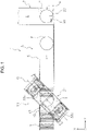
- FIG.1 is a schematic plan view of the carrying system of the first embodiment.
- a carrying system 1 has a function to carry a tire T (an example of an article) one by one, to stack a plurality of the tires T, and then to carry the stacked tires T.
- the carrying system 1 has a conveyer apparatus 3, which carries the tire T having a plurality of different-sized types.
- the conveyer apparatus 3 includes a first conveyer 5, a second conveyer 7, and a convertor 9.
- the convertor 9 is disposed between the first conveyer 5 and the second conveyer 7.
- the tire T are carried in the order of the second conveyer 7, the convertor 9 and the first conveyer 5.
- the first conveyer 5 and the second conveyer 7 are orthogonal to each other and the convertor 9 changes the conveying direction of tire T from the conveyer 7 to the conveyer 5.
- the first conveyer 5 and the second conveyer 7 are of a known technique, such as a roller conveyer, and have a carry surface 5a on which the tires T are conveyed.
- the convertor 9, which is of a known technique, is made of, for example, a roller conveyor and chain conveyors movable between the rollers of the roller conveyer. Members of the each device are omitted appropriately in order to simplify the drawings.
- an extending direction of the first conveyor 5 is referred to as a first direction (a Y direction) and an extending direction of the second conveyer 7 is referred to as a second direction (an X direction).
- the carrying system 1 has a centering stack device 11.
- the centering stack device 11 stacks the tires T while centering them.
- the stacked tires T are carried into a rack (not shown) directly by use of a robot arm (not shown). Unless each of the tires T is centered accurately, the plurality of tires T may incline and collapse when being gripped by the robot arm. Accordingly, an accurate centering is required.
- the embodiment of the present invention provides the centering stack device 11 that can solve the above-described issue (to be described later).
- the centering stack device 11 has a first positioning device 13, which defines a position of an end portion of the tire T carried by the first conveyer 5 as a first predetermined position in the first direction.
- the first positioning device 13 has a first stopper 15, which is provided at the first conveyer 5.
- the first stopper 15 protrudes upward from the carry surface 5a (an example of a placement section) of the first conveyer 5 and is capable of abutting against the tire T carried by the first conveyer 5 in the first direction.
- the first stopper 15 extends to the second direction.
- FIGS.2 and 3 are schematic side views of the first positioning device.
- the first positioning device 13 has a first stopper driver 17 which causes the first stopper 15 to move between an abutment position ( FIG.2 ) protruding upward from the carry surface 5a and a retreat position ( FIG.3 ) below the carry surface 5a distanced away obliquely downward from the abutment position at a downstream side in a conveyance direction of the tire T.
- the first stopper driver 17 is, for example, a pneumatic cylinder.
- the first stopper 15 of the carrying system 1 moves from the abutment position to the retreat position after the tire T abuts against the first stopper 15.
- the retreat position is so far from the tire T abutment position in the first direction that the load is not applied easily from the first stopper 15 to the tire T. Therefore, the position or direction of tire T is not changed easily. If rotation or wear of tire T is not considered, the first stopper may move only in the vertical direction.
- the centering stack device 11 has a second positioning device 23, which defines the end portion of the tire T in the second direction as a second predetermined position.
- the second positioning device 23 has a second stopper 25, which is disposed at one side of the second direction (the bottom of the FIG.1 ) on the converter 9.
- the second stopper 25 protrudes upward from the carry surface 9a of the convertor 9 and is capable of abutting against one side of the tire T.
- the second positioning device 23 has a driver 77 (refer to FIG.10 ) which moves the second stopper 25 between the abutment position protruding upward from the carry surface 5a and the retreat position distanced away from the abutment position against the tire T in the second direction.
- the driver 77 may have the same or similar structure as the one of the first stopper driver 17 of the first positioning device 13, or may have a structure that allows the second stopper 25 to retreat in the lateral direction. If rotation of the tire T is not considered, the second stopper 25 does not need to be retreated.
- the convertor 9 moves the tire T to one side of the second direction (the side of the second stopper 25 on the bottom of FIG.1 ) at the upstream side in conveyance direction from the first positioning device 13. This enables the tire T to abut against the second stopper 25 so as to be positioned in the second direction. Then the second stopper 25 moves from the abutment position to the retreat position. The abutment position against tire T is distanced far from the retreat position in the second direction, thus a load from the second stopper 25 is not applied easily to the tire T. Therefore, the position or direction of the tire T cannot be changed easily. Then the tire T is carried on the first conveyer 5 toward the first positioning device 13 in the first direction. In this process, the tire T is carried without changing the posture or the position determined in the second direction since no guide is provided at the back side (bottom side of FIG.1 ) of the first conveyer 5 in the second direction.
- the tire T is positioned in the first direction with the first stopper 15 at a stack position 61, which is a position where the tire T is stopped and occupied at the upstream side in a conveyance direction of the first stopper 15. As described above, the tire T is stopped at the stack position 61 on the first conveyer 5 with the first stopper 15 in a state in that the tire T is positioned in each of the first and second directions.
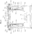
- FIG.4 is a schematic perspective view of the stacker and FIG.5 is a schematic front view of the stacker.
- the centering stack device 11 has a stacker 31 (an example of a gripping apparatus).
- the stacker 31 is used to stack a centered tire T.
- the stacker 31 has a pair of masts 31a and a ceiling 31b which connects the masts 31a with each other at the top.
- the pair of masts 31a are disposed at both sides of the first conveyer 5 across the stack position 61 of the first conveyer 5.
- the stacker 31 has a first gripping member 33a and a second gripping member 33b, which grip the sides of one or more tires T.
- the first gripping member 33a and the second gripping member 33b have a predetermined length in the vertical direction and circular-arc-shaped abutment surfaces 33a1 and 33b1 (an example of bent portions) in a plan view.
- the first gripping member 33a and the second gripping member 33b can grip and hold a tire T or two through ten stacked tires T at a time.
- the first gripping member 33a is placed at the same side as the second positioning device 23 in the second direction.
- the abutment surfaces 33a1 and 33b1 are bent parts and, thus, enable the first gripping member 33a and the second gripping member 33b to abut along the sides of the tire T.
- the stacker 31 has a first horizontal direction driver 34a and a second horizontal direction driver 34b to move the first gripping member 33a and the second gripping member 33b in the horizontal direction, respectively.
- the first horizontal direction driver 34a and the second horizontal direction driver 34b have a first vehicle 35a and a second vehicle 35b, a first chain 36a and a second chain 36b which drive the first vehicle 35a and the second vehicle 35b in a horizontal direction, a first sprocket 37a and a second sprocket 37b, a third sprocket 38a and a fourth sprocket 38b, and a first grip motor 39a and a second grip motor 39b, respectively.
- the stacker 31 has a first elevator 41a and a second elevator 41b.
- the first elevator 41a and the second elevator 41b are a pair of devices to elevate the first gripping member 33a and the second gripping member 33b, respectively.
- the first elevator 41a and the second elevator 41b are provided at the lower side of the first horizontal direction driver 34a and the second horizontal direction driver 34b, respectively.
- the first elevator 41a has a first lower sprocket 42a arranged at a lower side in a vertical direction, a first upper sprocket 43a arranged at an upper side in the vertical direction, and a first chain 44a to couple the first lower sprocket 42a and the first upper sprocket 43a to each other.
- the first gripping member 33a is fixed to the first chain 44a.
- the first elevator 41a further has a first elevator motor 45a to drive the first upper sprocket 43a so as to move the first gripping member 33a between an upper position and a lower position.
- the first elevator 41a further has a first guide 46a to guide the first gripping member 33a in a vertical direction.
- the second elevator 41b has a second lower sprocket 42b arranged at a lower side in a vertical direction, a second upper sprocket 43b arranged at an upper side in a vertical direction, and a second chain 44b to couple the second lower sprocket 42b and the second upper sprocket 43b to each other.
- the second gripping member 33b is fixed to the second chain 44b.
- the second elevator 41b further has a second elevator motor 45b to drive the second upper sprocket 43b so as to move the second gripping member 33b between the upper position and the lower position.
- the second elevator 41b further has a second guide 46b to guide the second gripping member 33b in a vertical direction.
- the above 'the upper position' of the first gripping member 33a and the second gripping member 33b means that the bottom ends of the first gripping member 33a and the second gripping member 33b are placed at a height that does not interfere with the lowermost tire T.
- the upper position may be based on a width of the biggest tire T or based on the types of tire T.
- the above 'the lower position' of the first gripping member 33a and the second gripping member 33b is a position where the bottom ends of the first gripping member 33a and the second gripping member 33b do not interfere with the first conveyer 5 when the first gripping member 33a and the second gripping member 33b grip a tire T placed on the first conveyer 5.
- the first gripping member 33a and the second gripping member 33b are positioned such that the bottom ends thereof are lower than the first lower sprocket 42a and the second lower sprocket 42b at the lower position. Therefore, even the bottommost one of a plurality of the tires T is able to be gripped by the first gripping member 33a and the second gripping member 33b.
- the first lower sprocket 42a and the second lower sprocket 42b are disposed at a position higher than the top surface of the highest tire T.
- the first lower sprocket 42a and the second lower sprocket 42b are disposed above the first conveyer 5
- the first lower sprocket 42a and the second lower sprocket 42b do not interrupt conveyance of the tire T.
- the stacker 31 includes a first sensor 73a and a second sensor 73b (examples of sensors) (Refer to FIGS. 6 , 10 ), which detect the tires T placed at the predetermined distance from the abutment surfaces 33a1, 33b1 of the first gripping member 33a and the second gripping member 33b, respectively.
- the first sensor 73a and the second sensor 73b which are optical transmission type sensor, include a light emitting section and a light receiving section provided at both right-left ends of the abutment surfaces 33a1, 33b1 of the first gripping member 33a and the second gripping member 33b.
- the abutment surfaces 33a1, 33ab have holes (not shown) through which the light axes of the first sensor 73a and the second sensor 73b passes.
- the light axes of the first sensor 73a and the second sensor 73b which are orthogonal to the movement direction of the first gripping member 33a and the second gripping member 33b, connect one end portion with another end portion of the circular arc of first gripping member 33a and second gripping member 33b in a plan view, respectively.
- the light axis crosses the circular arc by intersecting at the two points of the circular arc in a plan view, whereby the light axis is required to extend in the direction along the tire T. Therefore, for example, the light axis may be parallel to the line described above. In the present embodiment, the light axis extends in a horizontal direction.
- the stacker 31 has a tire height sensor 74 ( FIG.10 ) to detect the height of tire T.
- the type of the sensor 74 is not specifically limited.
- the tire height sensor 74 may be a plurality of optical transmission type or optical reflection sensors lined up in the height direction, or a distance measuring sensor disposed above the tire T. Further, the position of sensor is not specifically limited.
- the height of a tire T may be included in the tire information obtained from the upper controller (not shown).
- a controller 71 controls a drive amount of the first elevator motor 45a and the second elevator motor 45b in accordance with the height of tire T. This enables an elevation amount of the first gripping member 33a and the second gripping member 33b to be minimalized. As a result, an operational efficiency is improved.
- the stacker 31 has a tire arrival sensor 75 ( FIG.10 ) to detect that a tire T arrives at the stack position 61.
- the sensor 75 is an optical transmission type or light reflection type sensor or optical reflective type sensor installed at both sides of the first conveyer 5.
- the type of sensors is not specifically limited.
- a touch sensor installed at the first stopper 15 and detecting a contact with tire T is applicable.
- FIG.6 is a schematic partial plan view showing a gripping operation of a stacker.
- FIG. 6 shows a plurality of types of tires T1 to T5. These tires include a first tire portion t1 and a second tire portion t2.
- the first tire portion t1 is an end portion side determined with the first positioning device 13 and the second tire portion t2 is an end portion side determined with the second positioning device 23 after abutting against the first stopper 15 of the first positioning device 13.
- the position of the first tire portion t1 in the first direction is determined with the first stopper 15.
- the position of the second tire portion t2 in the second direction is determined with the second stopper 25 of the second positioning device 23 previously.
- the tire T does not rotate on the first conveyer 5 so that a portion of the tire T that abuts against the second stopper 25 becomes the second tire portion t2 at the stack position 61.
- FIG.6 shows only the first tire portion t1 and the second tire portion t2 of the tire T5.
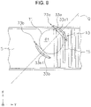
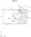
- FIGS. 7 to 9 are schematic partial plan views showing the stacker gripping operations.
- the tire T1 has the smallest size, that is, the shortest outside diameter.
- the first gripping member 33a and the second gripping member 33b pass between the first tire portion t1 and the second tire portion t2 of the tire T1 to grip the sides of the tire T.
- the first gripping member 33a and the second gripping member 33b grip the tire T obliquely against the first direction at the midpoint of a direct line P connecting the first tire portion t1 with the second tire portion t2.
- the first gripping member 33a and the second gripping member 33b may grip the tire T in the third direction (the extending direction of a direct line Q, clamp direction) horizontally orthogonal to the straight-line P. Further more specifically, the first gripping member 33a and the second gripping member 33b pass between the first tire portion t1 and the second tire portion t2 (on the straight-line P) and may grip the tire T obliquely at a 45-degree angle against the first direction. As described above, the center of the gripping direction coincides with the center of the tire T, so that the first gripping member 33a and the second gripping member 33b can grip correctly the tire T1 having a different-sized outside diameter. Further, the first positioning device 13 and the stacker 31 can be compact. In the present embodiment, regardless of the type of tire T, the center of the gripping direction is consistent with the center of tire T1, because the tire T is round-shaped and the center can be determined by positioning two points.
- the tire T1 is positioned by the first stopper 15.
- the first gripping member 33a and the second gripping member 33b move to the first position close to the side of the tire T1.
- the arrival at the first position is detected with the detection signal from the first sensor 73a and the second sensor 73b.
- the first gripping member 33a and the second gripping member 33b which have the first sensor 73a and the second sensor 73b, respectively, are bend and this enables the tire T1 to be detected before the first gripping member 33a and the second gripping member 33b abut against the tire T1.
- the first gripping member 33a and the second gripping member 33b arrive at the second position where the gripping members 33a and 33b abut against the side of the tire T1 to grip the tire T1.
- the detection signal from the first sensor 73a and the second sensor 73b confirms that the first gripping member 33a and the second gripping member 33b are gripping the tire T1.
- the tire T having a different-sized outside diameter can be detected in a non-contact manner before being gripped since the abutment surfaces 33a1, 33b1 of the first gripping member 33a and the second gripping member 33b are arc-shaped in a plan view. Further, the first sensor 73a and the second sensor 73b are non-contact sensors, so that mechanical parts or components of the tire detector can be reduced.
- the stacker 31 has a controller 71 (an example of a controller), which is a computer system including a processor, such as CPU, a memory device, such as ROM, RAM, HDD, and SSD, and various interfaces, such as A/D convertor, D/A convertor, and communication interface.
- the controller 71 runs a program stored in a memory (corresponding to a part or all of memory areas of a memory device) to perform various control operations.
- the controller 71 may be made of a single processor or a plurality of independent processors for each control.
- Each element of the controller 71 may function partially or in whole as a program executable with a computer system included in the controller 71.
- the functions of each element of the controller 71 may be partially made up of a custom IC.
- the controller 71 is connected to the first stopper driver 17, the first elevator motor 45a, the second elevator motor 45b, the first grip motor 39a, the second grip motor 39b, the first sensor 73a, the second sensor 73b, the tire height sensor 74, and the tire arrival sensor 75.
- the controller 71 is connected with a sensor (not shown) to detect the size, the shape, or the position of the tire T, a sensor (not shown) and a switch (not shown) to detect the condition of each device, and an information input device (not shown).
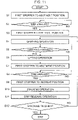
- FIG.11 is a flowchart showing stack controlling operations.
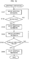
- FIG.12 is a flowchart showing tire gripping operations.
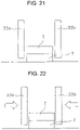
- FIGS. 13 to 25 are schematic diagrams showing an operating status of a pair of gripping members during stack operations.
- control flowchart described below is an example and each step can be removed or replaced as appropriate.
- a plurality of steps can be executed at a time or a part or all of steps can be executed together.
- Each step of the control flowchart is not limited to a single control operation and can be replaced by a plurality of control operations represented by a plurality of steps.
- the operation of each device, which is a result of instructions from the controller 71 to each device, is represented by each step of the software application.
- a series of operations are performed to stack the same size (type) tires T. After the series of operations are finished, tires of a different size (type) are stacked. However, the size (type) of tires does not need to be changed every operation.
- the tire T is positioned in the second direction with the second positioning device 23.
- the first stopper 15 moves to the abutment position.
- the controller 71 controls the first stopper driver 17 to move the first stopper 15 to the abutment position.
- step S2 the controller 71 detects the tire T arrival at the stack position 61 based on the detection signal from the tire arrival sensor 75. As shown in FIGS. 13 to 14 , after the tire T arrives, the process goes to step S3.
- the first stopper moves to the retreat position.
- the controller 71 controls the first stopper drive 17 to execute the above operation.
- the first gripping member 33a and the second gripping member 33b grip the tire T.
- step S101 the first gripping member 33a moves toward the tire T.
- step 102 whether the tire T is detected or not with the first sensor 73a is judged. If detected (if controller receives a detection signal from the first sensor 73a), the process goes to step S103. If not detected, the process returns to step S101.
- step S103 as shown in FIG.15 , the first gripping member 33a stops at the first position close to the side of tire T (the tire T is not gripped).
- step S104 as the condition for transferring from step S103 to step S104, status of the second gripping member 33b needs to be checked in order to prevent the second gripping member 33b from pushing the tire T when gripping.
- step S104 the first gripping member 33a further approaches the tire T and then, as shown in FIG. 16 , arrives at the second position to abut against the side of the tire T.
- step S105 whether the torque value of the first grip motor 39a reaches or not the specified value is judged. If it is reached, the process goes to step S106. If it is not reached, the process returns to step S104. At step S106, the movement of the first gripping member 33a is stopped.
- step S5 of FIG.11 completion of the gripping operations is awaited.
- the controller 71 judges the completion of gripping operations, for example, based on a torque of the first grip motor 39a and the second grip motor 39b.
- step S6 as shown in FIG.17 , the first gripping member 33a and the second gripping member 33b will go up to lift the tire T.
- the controller 71 controls the first elevator motor 45a and the second elevator motor 45b to perform the above operation.
- step S7 the first stopper 15 moves to the abutment position.
- step S8 the next tire T arrives at the stack position 61.
- the controller 71 judges the arrival based on the detection signal from the tire arrival sensor. As shown in FIG.18 , the process goes to step S9 in response to arrival of the next tire T.
- the first stopper 15 moves to the retreat position.
- step S10 as shown in FIG.19 , descending of the first gripping member 33a and the second gripping member 33b moves a gripped tire T down to another tire located thereunder.
- the controller 71 controls the first elevator motor 45a and the second elevator motor 45b to perform the above operation.
- the tires T are positioned at two points with the first positioning device 13 and the second positioning device 23, thus enabling the same to be stacked and centered precisely to each other.
- step S11 as shown in FIG.20 , an outward moving of the first gripping member 33a and the second gripping member 33b releases the grip.
- the controller 71 controls the first grip motor 39a and the second grip motor 39b to perform the above operation.
- the movement distance of the first gripping member 33a and the second gripping member 33b may be controlled with a timer.
- the first gripping member 33a and the second gripping member 33b are separated in the same or different distance.
- step S12 whether stacking operations are completed or not is judged. If completed, the process is finished. If not, the process returns to step S4.
- the first conveyer 5 conveys the stacked tires to the downstream side in the conveyance direction.
- Step S4 operations to grip a tire is performed.
- the detection signal from the first sensor 73a and the second sensor 73b is used only for confirming the existence of the tire T (to be described later).
- step S6 as shown in FIG. 24
- step S8 as shown in FIG. 25 , further next tire T is awaited.
- the position of tire T in the first direction is determined with the first positioning device 13 and the position in the second direction is determined with the second positioning device 23.
- the tire T is gripped between the first portion t1 of a tire and the second portion t2 of a tire with the first gripping member 33a and the second gripping member 33b. Accordingly, even the tire T with a different-sized outer diameter can be gripped correctly.
- the controller moves the first gripping member 33a and the second gripping member 33b close to each other and stop them at the first position. Then, the controller can memory the stop position and the grip position to determine the movement distance to the second position. Therefore, for the tire T carried in secondarily or later, the controller may move the first gripping member 33a and the second gripping member 33b to the second position without stopping at the first position to grip the tires T. After the first gripping member 33a and the second gripping member 33b stop at the second position for the tire T carried in secondarily or later, the controller 51 confirms using the first sensor 73a and the second sensor 73b that the tire T is gripped.
- the tire T carried in secondarily or later is not stopped at the first position, thus reducing the cycle time.
- the first sensor 73a and the second sensor 73b are used to stop the first gripping member 33a and the second gripping member 33b at the first position.
- the first sensor 73a and the second sensor 73b are used to confirm that the first gripping member 33a and the second gripping member 33b grip the tire T at the second position.
- the above control is usable for tire stacking and tire unstacking operations.
- the tire T carried in firstly is a first article and the tire T carried in secondarily or later is a second article.
- the bottommost tire T of the stacked tires T is a first article and the second and subsequent tires T from the bottom is a second article.
- tires T are stacked, for example, the stacked tires T are conveyed together by using a carrier which holds tires T at the inside or the lower side of the tires T. Although the stacked tire T is closer to one side in the second direction, the center of the tire T can be adjusted to the transfer position due to the same mechanism as a second direction adjustment conveyor.
- the carrier can hold the tire T at the fixed position.
- the light axis of the first sensor and the second sensor in the first embodiment is horizontal, however, may slant in a vertical direction.
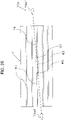
- FIG.26 is a schematic side view showing an association between a tire and light axes of sensors according to the second embodiment.
- the basic structures and operations are the same as those of the first embodiment and different points will now be described as follows.
- the first sensor 73a and the second sensor 73b have the same structures, thus only details of the first sensor 73a will be described.
- the first sensor 73a detects a tire T located at the predetermined distance from the abutment surface of the first gripping member 33a and the second gripping member 33b.
- the light axis 76 of the first sensor 73a is located so as to slant upward with respect to horizontal direction.
- a light emitting section 73a1 and a light receiving section 73a2 are installed on the upper side and the lower side, respectively. They may be installed upside down.
- a slanting angle of the light axis 76 is at approximately 5 degrees. The above angle can prevent the light axis 76 from penetrating into a groove 81 (to be described later) of tire T so as to ensure to detect a larger outer surface of the tire T.
- the tire T shown in FIG.26 has a plurality of grooves 81 extending in the circumference direction.
- the light axis 76 of the first sensor 73a is slant, which prevents the light axis 73 from penetrating into the groove 81.
- the tire T can be correctly detected.
- a detection area 83 on the top of gripping direction of the tire T is detected with the sensor.
- areas 85, 87 at both sides of the detection area 83 therewithin are detected.
- the light axis will penetrate into the grooves within the detection area and detection of the tire T will be delayed, so that the detected position may be incorrect.
- detection delay is avoidable.
- a controller confirms the detection of tire T with a sensor after a pair of gripping members stop at the first position.
- a controller may confirm the detection of tire T with a sensor without stopping the gripping members at the first position. In this case, if the detection of tire T cannot be confirmed, the pair of gripping members are stopped after passing the first position.
- FIG.27 is a flowchart showing a gripping operation in the third embodiment.
- step S101 the first gripping member 33a moves toward the tire T.
- step S102 whether the first sensor 73a has detected the tire T or not is judged. If detected, the process goes to step S105, and if not detected, the process goes to the step S107.
- the status of the second gripping member 33b is checked in order to prevent the tire T from being pushed when being gripped. As a result, the first gripping member 33a moves to the second position to abut the sides of the tire T.
- step 105 whether the torque value of the first grip motor 39a has achieved the specified value or not is judged. If achieved, the process goes to step S106. If not achieved, operation of step S105 is performed again.
- step 106 movement of the first gripping member 33a is stopped, and at step 107, whether the movement distance of the first gripping member 33a is over the predetermined distance or not is judged. If over the predetermined distance, the process goes to step S 108. If not, the process returns to step S101. At step S108, the movement of first gripping member 33a is stopped and an abnormality handling is performed.
- the above 'predetermined distance' is determined, for example, for each tire T.
- the 'predetermined distance' is defined such that the distance between the first gripping member 33a and the second gripping member 33b is the same as or smaller than the width that allows the tire T to be detected with non-contact, or the same as or smaller than the diameter of the tire T.
- the gripping apparatus such as a stacker 31, includes a placement section, a pair of gripping members, sensors, and a controller.
- the placement section such as a carry surface 5a, holds round-shaped articles, such as tires T.
- the pair of gripping members such as a first gripping member 33a and a second gripping member 33b grip the sides of an article placed on the placement section and include an abutment surface (such as abutment surfaces 33a1, 33b1) including a bent part and capable of abutting against the side of the article.
- an abutment surface such as abutment surfaces 33a1, 33b1
- the sensors such as a first sensor 73a and a second sensor 73b crosses a bent portion and have a light axis in the direction along an article.
- the controller such as a controller 50, moves the pair of gripping members close to each other toward the first position (for example, FIG.8 ) where an article is not gripped.
- the controller moves the pair of gripping members close to each other to the second position where the article is gripped (for example, FIG.9 ).
- the pair of gripping members have the bent portion and the article is round-shaped, so that the article can be detected with non-contact before being gripped. Therefore, even the article having a different-sized diameter can be correctly detected.
- the senor is of a non-contact type, thus enabling to reduce parts or components of a tire detector.
- first gripping member and second gripping member Abutment surfaces of a first gripping member and a second gripping member may have a V-shape in a plan view.
- the controller moves a pair of gripping members toward a tire at a time.
- the controller may move the pair of gripping members at different times. For example, one gripping member may move to abut against a tire and then the other gripping member moves to abut against the tire to grip the tire.
- a gripping apparatus may be used for the devices other than a stacker.
- the embodiment of the present invention may be applied to not only article stacking operations but also article unstacking operations. For example, positioning operations may be performed for the unstacking operations in the same way as that for the stacking operations.
- a round-shaped article is not limited to a tire.
- the embodiments of the present invention are widely applicable to a gripping apparatus to grip a round-shaped article.
Landscapes
- Engineering & Computer Science (AREA)
- Mechanical Engineering (AREA)
- Automation & Control Theory (AREA)
- Civil Engineering (AREA)
- Structural Engineering (AREA)
- Tyre Moulding (AREA)
- Load-Engaging Elements For Cranes (AREA)
- Stacking Of Articles And Auxiliary Devices (AREA)
- Automobile Manufacture Line, Endless Track Vehicle, Trailer (AREA)
Applications Claiming Priority (2)
| Application Number | Priority Date | Filing Date | Title |
|---|---|---|---|
| JP2020018905 | 2020-02-06 | ||
| PCT/JP2020/035017 WO2021157117A1 (ja) | 2020-02-06 | 2020-09-16 | 挟持装置及び段積み装置 |
Publications (2)
| Publication Number | Publication Date |
|---|---|
| EP4101804A1 true EP4101804A1 (de) | 2022-12-14 |
| EP4101804A4 EP4101804A4 (de) | 2024-02-28 |
Family
ID=77199812
Family Applications (1)
| Application Number | Title | Priority Date | Filing Date |
|---|---|---|---|
| EP20917483.8A Pending EP4101804A4 (de) | 2020-02-06 | 2020-09-16 | Klemmvorrichtung und stapelvorrichtung |
Country Status (7)
| Country | Link |
|---|---|
| US (1) | US11858755B2 (de) |
| EP (1) | EP4101804A4 (de) |
| JP (1) | JP7276520B2 (de) |
| KR (1) | KR102682380B1 (de) |
| CN (1) | CN115038663B (de) |
| TW (1) | TWI840651B (de) |
| WO (1) | WO2021157117A1 (de) |
Families Citing this family (3)
| Publication number | Priority date | Publication date | Assignee | Title |
|---|---|---|---|---|
| JP7192960B2 (ja) * | 2019-02-19 | 2022-12-20 | 村田機械株式会社 | 搬送システム |
| JP7448040B2 (ja) * | 2021-01-21 | 2024-03-12 | 村田機械株式会社 | タイヤ搬送装置 |
| CN116142957B (zh) * | 2023-04-21 | 2023-07-04 | 河南钰润建筑工程有限公司 | 一种预制柱吊装装置 |
Family Cites Families (25)
| Publication number | Priority date | Publication date | Assignee | Title |
|---|---|---|---|---|
| JPS59353B2 (ja) * | 1980-07-24 | 1984-01-06 | ファナック株式会社 | 把持装置 |
| US4507078A (en) * | 1983-03-28 | 1985-03-26 | Silicon Valley Group, Inc. | Wafer handling apparatus and method |
| USH65H (en) * | 1983-05-27 | 1986-05-06 | At&T Bell Laboratories | Dynamic optical sensing: Robotic system and manufacturing method utilizing same |
| JPH072530B2 (ja) * | 1984-07-25 | 1995-01-18 | 株式会社ブリヂストン | タイヤの段積み装置 |
| JPS6171302A (ja) * | 1984-09-14 | 1986-04-12 | Toshiba Corp | ロボットハンド用近接センサ装置 |
| JPS61176187U (de) * | 1985-04-22 | 1986-11-04 | ||
| US4849643A (en) * | 1987-09-18 | 1989-07-18 | Eaton Leonard Technologies | Optical probe with overlapping detection fields |
| US5008555A (en) * | 1988-04-08 | 1991-04-16 | Eaton Leonard Technologies, Inc. | Optical probe with overlapping detection fields |
| US5177563A (en) * | 1989-02-01 | 1993-01-05 | Texas A&M University System | Method and apparatus for locating physical objects |
| JP3734607B2 (ja) * | 1997-08-01 | 2006-01-11 | 本田技研工業株式会社 | タイヤの位置決め搬送装置 |
| JPH11228070A (ja) * | 1998-02-19 | 1999-08-24 | Murata Mach Ltd | 天井走行車 |
| JP2000247569A (ja) * | 1999-03-01 | 2000-09-12 | Nkk Corp | 金属帯コイル運搬用リフタ− |
| TW558058U (en) * | 2002-05-03 | 2003-10-11 | Nanya Technology Corp | Wafer carrying apparatus |
| CN201012864Y (zh) * | 2007-03-12 | 2008-01-30 | 江苏天奇物流系统工程股份有限公司 | 轮胎堆垛机 |
| US8078315B2 (en) * | 2008-05-08 | 2011-12-13 | Cascade Corporation | Control system for a load handling clamp |
| US9310791B2 (en) * | 2011-03-18 | 2016-04-12 | Siemens Healthcare Diagnostics Inc. | Methods, systems, and apparatus for calibration of an orientation between an end effector and an article |
| CN202967877U (zh) * | 2012-12-12 | 2013-06-05 | 武汉钢铁(集团)公司 | 卧卷夹钳防夹伤装置 |
| EP2832676B1 (de) * | 2013-07-29 | 2016-10-19 | Siemens Aktiengesellschaft | Rotorblattgreifvorrichtung |
| JP2015119066A (ja) * | 2013-12-19 | 2015-06-25 | 株式会社安川電機 | 検出システムおよび検出方法 |
| JP6270595B2 (ja) * | 2014-04-01 | 2018-01-31 | 鈴鹿エンヂニヤリング株式会社 | ベールゴムの吊り揚げ搬送方法及びその装置 |
| JP6256702B2 (ja) * | 2014-12-25 | 2018-01-10 | 株式会社ダイフク | 物品搬送用容器昇降搬送装置 |
| JP2019028010A (ja) * | 2017-08-03 | 2019-02-21 | 株式会社ミツトヨ | パイプ測定装置 |
| US10662002B2 (en) | 2017-12-26 | 2020-05-26 | Cynergy Ergonomics, Inc. | Tire manipulator |
| CN209957229U (zh) * | 2019-01-17 | 2020-01-17 | 南通申东裕浩轮胎有限公司 | 一种大型轮胎夹具 |
| JP7192960B2 (ja) * | 2019-02-19 | 2022-12-20 | 村田機械株式会社 | 搬送システム |
-
2020
- 2020-09-16 WO PCT/JP2020/035017 patent/WO2021157117A1/ja not_active Ceased
- 2020-09-16 US US17/796,711 patent/US11858755B2/en active Active
- 2020-09-16 KR KR1020227030541A patent/KR102682380B1/ko active Active
- 2020-09-16 CN CN202080095444.1A patent/CN115038663B/zh active Active
- 2020-09-16 JP JP2021575600A patent/JP7276520B2/ja active Active
- 2020-09-16 EP EP20917483.8A patent/EP4101804A4/de active Pending
-
2021
- 2021-01-29 TW TW110103353A patent/TWI840651B/zh active
Also Published As
| Publication number | Publication date |
|---|---|
| CN115038663A (zh) | 2022-09-09 |
| TW202134163A (zh) | 2021-09-16 |
| US20230109072A1 (en) | 2023-04-06 |
| JP7276520B2 (ja) | 2023-05-18 |
| WO2021157117A1 (ja) | 2021-08-12 |
| CN115038663B (zh) | 2025-10-31 |
| TWI840651B (zh) | 2024-05-01 |
| KR102682380B1 (ko) | 2024-07-04 |
| US11858755B2 (en) | 2024-01-02 |
| EP4101804A4 (de) | 2024-02-28 |
| KR20220136415A (ko) | 2022-10-07 |
| JPWO2021157117A1 (de) | 2021-08-12 |
Similar Documents
| Publication | Publication Date | Title |
|---|---|---|
| EP4101804A1 (de) | Klemmvorrichtung und stapelvorrichtung | |
| CN113348143B (zh) | 输送系统 | |
| CA2472434A1 (en) | Materials handling system | |
| US20070248448A1 (en) | Apparatus and process for the automatic palletising and/or depalletising of containers | |
| TWI740999B (zh) | 物品搬送設備 | |
| CN112455988A (zh) | 出库分拣设备及其控制方法 | |
| CN104192551A (zh) | 料管处理装置 | |
| WO2024016476A1 (zh) | 一种裸瓶预编组成垛装置、成垛方法及包装设备 | |
| CN104973418A (zh) | 工件输送系统 | |
| US10471602B2 (en) | Magazine transfer unit gripper | |
| CN215881680U (zh) | 一种抓手装置及机械臂 | |
| EP4687172A1 (de) | Waferausrichter | |
| KR20130134317A (ko) | 슬라브 포지션 확인장치 | |
| KR100971597B1 (ko) | 사이드 에지 클램프형 멀티 핑거 로봇 | |
| JP2002326721A (ja) | タイヤの受渡し装置 | |
| JP2023126020A (ja) | 整列システム | |
| CN204173549U (zh) | 料管处理装置 | |
| JPH0750653Y2 (ja) | ワーク寸法検出装置 | |
| JP2002179244A (ja) | 整列装置 | |
| JP3830617B2 (ja) | フリーフローコンベアにおける搬送パレットの分離・セットの方法とシステム | |
| JPH11314759A (ja) | 平板段積装置 | |
| JPH05286544A (ja) | ロボットパレタイザ用ワーク位置決め装置 | |
| JP2018024096A (ja) | ワーク搬送システム |
Legal Events
| Date | Code | Title | Description |
|---|---|---|---|
| STAA | Information on the status of an ep patent application or granted ep patent |
Free format text: STATUS: THE INTERNATIONAL PUBLICATION HAS BEEN MADE |
|
| PUAI | Public reference made under article 153(3) epc to a published international application that has entered the european phase |
Free format text: ORIGINAL CODE: 0009012 |
|
| STAA | Information on the status of an ep patent application or granted ep patent |
Free format text: STATUS: REQUEST FOR EXAMINATION WAS MADE |
|
| 17P | Request for examination filed |
Effective date: 20220802 |
|
| AK | Designated contracting states |
Kind code of ref document: A1 Designated state(s): AL AT BE BG CH CY CZ DE DK EE ES FI FR GB GR HR HU IE IS IT LI LT LU LV MC MK MT NL NO PL PT RO RS SE SI SK SM TR |
|
| DAV | Request for validation of the european patent (deleted) | ||
| DAX | Request for extension of the european patent (deleted) | ||
| A4 | Supplementary search report drawn up and despatched |
Effective date: 20240129 |
|
| RIC1 | Information provided on ipc code assigned before grant |
Ipc: B65G 57/30 20060101ALI20240123BHEP Ipc: B65G 57/03 20060101ALI20240123BHEP Ipc: B65G 47/90 20060101ALI20240123BHEP Ipc: B29D 30/00 20060101ALI20240123BHEP Ipc: B25J 15/08 20060101ALI20240123BHEP Ipc: B66C 13/22 20060101ALI20240123BHEP Ipc: B66C 1/28 20060101AFI20240123BHEP |
|
| STAA | Information on the status of an ep patent application or granted ep patent |
Free format text: STATUS: EXAMINATION IS IN PROGRESS |
|
| 17Q | First examination report despatched |
Effective date: 20250814 |