EP4016775B1 - Verbinder für vorrichtung - Google Patents
Verbinder für vorrichtung Download PDFInfo
- Publication number
- EP4016775B1 EP4016775B1 EP21207992.5A EP21207992A EP4016775B1 EP 4016775 B1 EP4016775 B1 EP 4016775B1 EP 21207992 A EP21207992 A EP 21207992A EP 4016775 B1 EP4016775 B1 EP 4016775B1
- Authority
- EP
- European Patent Office
- Prior art keywords
- electric wire
- holding portion
- connector
- housing
- tube
- Prior art date
- Legal status (The legal status is an assumption and is not a legal conclusion. Google has not performed a legal analysis and makes no representation as to the accuracy of the status listed.)
- Active
Links
Images




Classifications
-
- H—ELECTRICITY
- H01—ELECTRIC ELEMENTS
- H01B—CABLES; CONDUCTORS; INSULATORS; SELECTION OF MATERIALS FOR THEIR CONDUCTIVE, INSULATING OR DIELECTRIC PROPERTIES
- H01B17/00—Insulators or insulating bodies characterised by their form
- H01B17/56—Insulating bodies
- H01B17/58—Tubes, sleeves, beads, or bobbins through which the conductor passes
- H01B17/583—Grommets; Bushings
-
- H—ELECTRICITY
- H01—ELECTRIC ELEMENTS
- H01R—ELECTRICALLY-CONDUCTIVE CONNECTIONS; STRUCTURAL ASSOCIATIONS OF A PLURALITY OF MUTUALLY-INSULATED ELECTRICAL CONNECTING ELEMENTS; COUPLING DEVICES; CURRENT COLLECTORS
- H01R13/00—Details of coupling devices of the kinds covered by groups H01R12/70 or H01R24/00 - H01R33/00
- H01R13/58—Means for relieving strain on wire connection, e.g. cord grip, for avoiding loosening of connections between wires and terminals within a coupling device terminating a cable
- H01R13/5804—Means for relieving strain on wire connection, e.g. cord grip, for avoiding loosening of connections between wires and terminals within a coupling device terminating a cable comprising a separate cable clamping part
- H01R13/5812—Means for relieving strain on wire connection, e.g. cord grip, for avoiding loosening of connections between wires and terminals within a coupling device terminating a cable comprising a separate cable clamping part the cable clamping being achieved by mounting the separate part on the housing of the coupling device
-
- H—ELECTRICITY
- H01—ELECTRIC ELEMENTS
- H01R—ELECTRICALLY-CONDUCTIVE CONNECTIONS; STRUCTURAL ASSOCIATIONS OF A PLURALITY OF MUTUALLY-INSULATED ELECTRICAL CONNECTING ELEMENTS; COUPLING DEVICES; CURRENT COLLECTORS
- H01R13/00—Details of coupling devices of the kinds covered by groups H01R12/70 or H01R24/00 - H01R33/00
- H01R13/62—Means for facilitating engagement or disengagement of coupling parts or for holding them in engagement
- H01R13/639—Additional means for holding or locking coupling parts together, after engagement, e.g. separate keylock, retainer strap
-
- H—ELECTRICITY
- H01—ELECTRIC ELEMENTS
- H01B—CABLES; CONDUCTORS; INSULATORS; SELECTION OF MATERIALS FOR THEIR CONDUCTIVE, INSULATING OR DIELECTRIC PROPERTIES
- H01B17/00—Insulators or insulating bodies characterised by their form
- H01B17/56—Insulating bodies
- H01B17/66—Joining insulating bodies together, e.g. by bonding
-
- H—ELECTRICITY
- H01—ELECTRIC ELEMENTS
- H01R—ELECTRICALLY-CONDUCTIVE CONNECTIONS; STRUCTURAL ASSOCIATIONS OF A PLURALITY OF MUTUALLY-INSULATED ELECTRICAL CONNECTING ELEMENTS; COUPLING DEVICES; CURRENT COLLECTORS
- H01R13/00—Details of coupling devices of the kinds covered by groups H01R12/70 or H01R24/00 - H01R33/00
- H01R13/46—Bases; Cases
-
- H—ELECTRICITY
- H01—ELECTRIC ELEMENTS
- H01R—ELECTRICALLY-CONDUCTIVE CONNECTIONS; STRUCTURAL ASSOCIATIONS OF A PLURALITY OF MUTUALLY-INSULATED ELECTRICAL CONNECTING ELEMENTS; COUPLING DEVICES; CURRENT COLLECTORS
- H01R13/00—Details of coupling devices of the kinds covered by groups H01R12/70 or H01R24/00 - H01R33/00
- H01R13/58—Means for relieving strain on wire connection, e.g. cord grip, for avoiding loosening of connections between wires and terminals within a coupling device terminating a cable
- H01R13/5804—Means for relieving strain on wire connection, e.g. cord grip, for avoiding loosening of connections between wires and terminals within a coupling device terminating a cable comprising a separate cable clamping part
- H01R13/5816—Means for relieving strain on wire connection, e.g. cord grip, for avoiding loosening of connections between wires and terminals within a coupling device terminating a cable comprising a separate cable clamping part for cables passing through an aperture in a housing wall, the separate part being captured between cable and contour of aperture
-
- H—ELECTRICITY
- H01—ELECTRIC ELEMENTS
- H01R—ELECTRICALLY-CONDUCTIVE CONNECTIONS; STRUCTURAL ASSOCIATIONS OF A PLURALITY OF MUTUALLY-INSULATED ELECTRICAL CONNECTING ELEMENTS; COUPLING DEVICES; CURRENT COLLECTORS
- H01R13/00—Details of coupling devices of the kinds covered by groups H01R12/70 or H01R24/00 - H01R33/00
- H01R13/62—Means for facilitating engagement or disengagement of coupling parts or for holding them in engagement
-
- H—ELECTRICITY
- H02—GENERATION; CONVERSION OR DISTRIBUTION OF ELECTRIC POWER
- H02G—INSTALLATION OF ELECTRIC CABLES OR LINES, OR OF COMBINED OPTICAL AND ELECTRIC CABLES OR LINES
- H02G15/00—Cable fittings
- H02G15/007—Devices for relieving mechanical stress
-
- H—ELECTRICITY
- H02—GENERATION; CONVERSION OR DISTRIBUTION OF ELECTRIC POWER
- H02G—INSTALLATION OF ELECTRIC CABLES OR LINES, OR OF COMBINED OPTICAL AND ELECTRIC CABLES OR LINES
- H02G3/00—Installations of electric cables or lines or protective tubing therefor in or on buildings, equivalent structures or vehicles
- H02G3/02—Details
- H02G3/06—Joints for connecting lengths of protective tubing or channels, to each other or to casings, e.g. to distribution boxes; Ensuring electrical continuity in the joint
- H02G3/0616—Joints for connecting tubing to casing
- H02G3/0625—Joints for connecting tubing to casing with means for preventing disengagement of conductors
-
- H—ELECTRICITY
- H01—ELECTRIC ELEMENTS
- H01B—CABLES; CONDUCTORS; INSULATORS; SELECTION OF MATERIALS FOR THEIR CONDUCTIVE, INSULATING OR DIELECTRIC PROPERTIES
- H01B17/00—Insulators or insulating bodies characterised by their form
- H01B17/26—Lead-in insulators; Lead-through insulators
- H01B17/265—Fastening of insulators to support
Definitions
- the present invention relates to a connector for device.
- a wide variety of electronic devices are mounted on automobiles, and wire harnesses are wired to transmit electric power, control signals and the like to the electronic devices.
- the wire harness includes a plurality of electric wires and a connector, and the connector is fitted to a connector of the electronic device or to a connector of another wire harness for connection with said electronic device or said another wire harness.
- a connector used for the wire harness as described above there is disclosed a connector including a connector housing that houses a terminal connected to an end of an electric wire and a rear holder that is attached to the connector housing (see Patent Document 1).
- a connector housing that houses a terminal connected to an end of an electric wire and a rear holder that is attached to the connector housing
- a conventional connector disclosed in Patent Document 1 includes a connector housing that houses a terminal connected to an end of an electric wire and a rear holder that is attached to the connector housing.
- the rear holder includes a pair of divided portions and a hinge for connecting the pair of divided portions.
- Each divided portion has a plate-shaped divided portion body and a gutter-shaped portion standing from the divided portion body. That is, the gutter-shaped portion is standing in a direction away from the connector housing.
- the pair of divided portions is configured such that, in a state where they are brought close to each other, the gutter-shaped portions form an electric wire holding portion in which the electric wire is inserted and held.
- Patent Document 1 JP 2015-125846 A
- the electric wire holding portion is provided so as to stand (project) in the direction away from the connector housing (the direction in which the electric wire extends).
- its outermost shape is defined by the electric wire holding portion, which causes an increase in size.
- An object of the present invention is to provide a connector for device which is downsized.
- the present invention provides a connector for device according to the features of claim 1.
- the electric wire holding portion of the front holder does not project to the outside of the device housing, thereby downsizing the connector for device in the direction in which the electric wire extends.
- the electric wire holding portion is positioned inside the housing, an access thereto from the outside is blocked and thus the electric wire holding portion is protected.
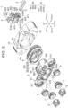
- FIG. 1 is a perspective view showing a connector for device 1 according to an embodiment of the present invention, in which the connector for device 1 is attached to a device housing 10 having an opening 10a (hole).
- FIG. 2 is a cross-sectional view of FIG. 1 .
- FIG. 3 is an exploded perspective view showing the connector for device 1.
- the connector for device 1 according to this embodiment is configured to be attached to the opening 10a (a hole shown in FIG. 2 ) of the device housing 10 to constitute a wire harness to be wired on an automobile or the like.
- the connector for device 1 is fixed to the device housing 10 by bolts 11 and in this state it is mounted on a vehicle.
- the connector for device 1 is configured to hold a pair of electric wires 2, 2 (shown in FIG. 2 ) inserted into the opening 10a of the device housing 10, and includes a housing 3 into which the electric wires 2 are inserted and which is fixed to the device housing 10, a front holder 4 configured to be engaged with the housing 3, and a binding band 5 configured to be wound around the front holder 4 such that the electric wires 2 are held to the front holder 4.
- a direction in which the opening 10a (hole) penetrates the device housing 10 may be referred to as "front-back direction”
- one direction which is orthogonal to “front-back direction” may be referred to as “left-right direction”
- another direction orthogonal to "front-back direction” may be referred to as “up-down direction”.
- the housing 3 includes a plate-shaped device fixing portion 31 and a tube-shaped insertion portion 32 which are integrally formed.
- the plate-shaped device fixing portion 31 is configured to be fixed, by bolts, to a front face of the device housing 10, and the tube-shaped insertion portion 32 is formed to extend forward in a tube shape from the device fixing portion 31 and communicates with a later-described pair of electric wire insertion portions 310, 310 of the device fixing portion 31, and the tube-shaped insertion portion 32 is configured to be inserted into the opening 10a of the device housing 10.
- the device fixing portion 31 is provided with a pair of bolt insertion portions 311, 311 into which a pair of bolts 11, 11 (shown in FIG. 2 ) is inserted, respectively, and the pair of electric wire insertion portions 310, 310 into which the pair of electric wires 2, 2 is inserted, respectively.
- the pair of electric wire insertion portions 310, 310 is disposed adjacent to each other in the right-left direction, and the pair of bolt insertion portions 311, 311 is disposed on both right and left sides of the pair of electric wire insertion portions 310, 310.
- each bolt insertion portion 311 is formed in a circular tube shape and is arranged such that an axis thereof extends in the front-back direction.
- Each bolt insertion portion 311 is configured such that, in a state where the device fixing portion 31 is placed on the front face of the device housing 10, the bolt 11 is inserted into each bolt insertion portion 311 and is screwed to a screw hole 101 of the device housing 10.
- a bolt sealing member 6 is interposed between each bolt insertion portion 311 and the bolt 11.
- each electric wire insertion portion 310 is formed in a circular tube shape and is arranged such that an axis thereof extends in the front-back direction.
- An electric wire sealing member 7 and an electric wire exterior member 8 that is disposed behind the electric wire sealing member 7 are provided inside each electric wire insertion portion 310.
- the electric wire sealing member 7 is configured to be press-fitted into the electric wire insertion portion 310 with the electric wire 2 being inserted into the electric wire sealing member 7.
- the electric wire exterior member 8 is configured to be engaged with a rear edge 310a of the electric wire insertion portion 310 with the electric wire 2 being inserted into the electric wire exterior member 8.
- the tube-shaped insertion portion 32 is formed in an oblong tube shape and includes a pair of flat plate portions 321, 321 opposing in the up-down direction (only one of which is shown in FIG. 3 ) and a pair of arcuate portions 322, 322 that is continuous with the pair of flat plate portions 321, 321.
- the tube-shaped insertion portion 32 communicates with the pair of electric wire insertion portions 310, 310, so the electric wires 2 are inserted therein.
- the tube-shaped insertion portion 32 is configured to be inserted into the opening 10a of the device housing 10 in a state where the device fixing portion 31 is placed on the surface of the device housing 10. Further, the tube-shaped insertion portion 32 is inserted into a device packing 9. With the tube-shaped insertion portion 32 being inserted into the device packing 9, the tube-shaped insertion portion 32 is inserted into the opening 10a of the device housing 10.
- the tube-shaped insertion portion 32 is provided with a to-be-locked portion 323 with which a locking portion 42 of the front holder 4 is engaged.
- the to-be-locked portion 323 is disposed at a front end of the tube-shaped insertion portion 32 and is configured to be exposed in a state where the tube-shaped insertion portion 32 is inserted into the device packing 9.
- the to-be-locked portion 323 is constituted of four to-be-locked holes 323A (only two of which are shown in FIG. 3 ).
- the four to-be-locked holes 323A are provided such that two of which are provided to each flat plate portion 321, and the two to-be-locked holes 323A, 323A provided in each flat plate portion 321 are arranged side by side in the right-left direction.
- the front holder 4 includes the electric wire holding portion 41 and the locking portion 42 which are integrally formed.
- the electric wire holding portion 41 is configured such that the binding band 5 (shown in FIG. 2 ) is wound around it to hold respective electric wires 2 (shown by a chain line in FIG. 4 ) on both right and left sides.
- the locking portion 42 is continuous with the front side of the electric wire holding portion 41 and is configured to be engaged with the to-be-locked portion 323 of the tube-shaped insertion portion 32 of the housing 3.
- the electric wire holding portion 41 includes a holding portion body 411 and each pair of electric wire supporting portions 412R (412L), 412R (412L) projecting to the right direction and to the left direction from both ends in the front-back direction of the holding portion body 411.
- the pair of electric wire supporting portions 412R, 412R is disposed on the right side of the holding portion body 411, and the pair of electric wire supporting portions 412L, 412L is disposed on the left side of the holding portion body 411.
- the pair of electric wire supporting portions 412R, 412R and the pair of electric wire supporting portions 412L, 412L have the same function or the same configuration, thus the pair of electric wire supporting portions 412L, 412L will be explained below and the explanation of the pair of electric wire supporting portions 412R, 412R is omitted.
- the holding portion body 411 is formed in a plate shape extending in the front-back direction between the pair of electric wire supporting portions 412L, 412L.
- the holding portion body 411 is provided with a flat face (hereinafter referred to as the bottom face 4A) extending in the front-back direction and in the up-down direction.
- the pair of electric wire supporting portions 412L, 412L is provided to project to the left from the bottom face 4A of the holding portion body 411. That is, the bottom face 4A is a face on which a basal portion of each electric wire supporting portion 412L is provided.
- each electric wire supporting portion 412L is formed in a plate shape extending in a plane direction including the up-down direction and the right-left direction (i.e., a plane direction intersecting a direction in which the electric wire 2 extends), and a left edge of each electric wire supporting portion 412L (i.e., an edge thereof in the projecting direction) is cut out to form a recessed portion 413 for accommodating each electric wire 2.
- each recessed portion 413 is formed in a semicircular shape having substantially the same curvature as an outer diameter of the electric wire 2, and in each recessed portion 413, a bottom portion 413a (shown in FIG.
- the locking portion 42 includes a standing portion 421 standing toward the front of the electric wire holding portion 41, a plate-shaped portion 422 continuous with the standing portion 421 and extending in the plane direction including the up-down direction and the right-left direction, and locking pieces 423 which are formed to extend backward from respective upper and lower edges of the plate-shaped portion 422 so as to be engaged with the to-be-locked portion 323 of the housing 3.
- each recessed portion 426 is formed in a semicircular shape having substantially the same curvature as the outer diameter of the electric wire 2.
- Each recessed portion 426 is arranged linearly in front of each recessed portion 413.
- each locking piece 423 includes a plate-shaped extended piece 424 which is formed to extend backward from the upper and lower edges of the plate-shaped portion 422, and a locking projection 425 which is provided at the extended piece 424 to be engaged with the to-be-locked hole 323A of the housing 3.
- the extended piece 424 is provided to face an outer face of each flat plate portion 321 of the tube-shaped insertion portion 32 of the housing 3, and when the locking projection 425 is fitted into the to-be-locked hole 323A, the to-be-locked portion 323 of the tube-shaped insertion portion 32 is engaged with the locking portion 42 of the front holder 4.
- the tube-shaped insertion portion 32 of the housing 3 is inserted into the device packing 9 so the device packing 9 is mounted on the tube-shaped insertion portion 32.
- the electric wire 2 is inserted into the electric wire sealing member 7 and the electric wire exterior member 8 such that the electric wire exterior member 8 is positioned behind the electric wire sealing member 7.
- a part of each electric wire 2 located on the front with respect to the electric wire sealing member 7 is sequentially inserted into each electric wire insertion portion 310 of the device fixing portion 31 and into the tube-shaped insertion portion 32 of the housing 3, and is drawn out to the front of the tube-shaped insertion portion 32.
- the respective electric wires 2 are positioned on both left and right sides of the holding portion body 411 of the electric wire holding portion 41 of the front holder 4, and the electric wires 2 are accommodated in the respective recessed portions 413 of the pair of electric wire supporting portions 412L, 412L and accommodated in the respective recessed portions 413 of the pair of electric wire supporting portions 412R, 412R.
- the binding band 5 is wound around the holding portion body 411 and around the pair of electric wires 2, 2.
- the binding band 5 is wound around the holding portion body 411 such that an axis thereof is arranged in the front-back direction.
- the binding band 5 squeezes the respective electric wires 2 such that the electric wires 2 approach the bottom face 4A of the holding portion body 411, thereby bending the respective electric wires 2 such that the electric wires 2 approach the bottom face 4A of the holding portion body 411.
- the pair of electric wires 2, 2 is held to the electric wire holding portion 41 of the front holder 4.
- the front holder 4 is moved close to the tube-shaped insertion portion 32 of the housing 3.
- the respective locking projections 425 of the locking pieces 423 abut on the front edges of the pair of flat plate portions 321, 321 of the tube-shaped insertion portion 32, and the extended pieces 424 are bent outward so the respective locking projections 425 get onto the respective flat plate portions 321, and then the locking projections 425 are engaged with the to-be-locked holes 323A.
- the locking portion 42 is engaged with the tube-shaped insertion portion 32 of the housing 3.
- the electric wire holding portion 41 of the front holder 4 is positioned inside the housing 3 in a state where the locking portion 42 is engaged with the housing 3.
- each electric wire sealing member 7 and each electric wire exterior member 8 are moved forward with respect to each electric wire 2.
- Each electric wire sealing member 7 and each electric wire exterior member 8 are inserted into (press fitted to) each electric wire insertion hole 310, and each electric wire exterior member 8 is engaged with the rear edge 310a of each electric wire insertion portion 310.
- the electric wire sealing member 7 and the electric wire exterior member 8 are installed at a predetermined position on each electric wire 2, thereby supporting each electric wire 2 on the electric wire insertion portion 310. In this way, the connector for device 1 is assembled.
- each electric wire 2 located on the front with respect to the front holder 4 is inserted into the opening 10a of the device housing 10 from the back side and is drawn out to the front of the opening 10a of the device housing 10, and the tube-shaped insertion portion 32 of the housing 3 is inserted into the opening 10a of the device housing 10 from the back side to place the device fixing portion 31 on the surface of the device housing 10.
- the bolt sealing member 6 is inserted into each bolt insertion portion 311, and the bolt 11 is inserted into the bolt insertion portion 311 and screwed to the screw hole 101 of the device housing 10.
- the connector for device 1 is attached to the device housing 10.
- the front holder 4 is configured such that, in a state where the locking portion 42 is engaged with the housing 3, the electric wire holding portion 41 is positioned inside the tube-shaped insertion portion 32 that is to be inserted into the opening 10a of the device housing 10 of the housing 3.
- the electric wire holding portion 41 since the electric wire holding portion 41 is positioned inside the tube-shaped insertion portion 32 of the housing 3, the electric wire holding portion 41 does not project to the outside (i.e., to the front) of the device housing 10 in the state where the connector for device 1 is attached to the device housing 10, thus the connector projecting height from the device housing 10 is reduced and the downsizing in the front-back direction (the direction in which the electric wire 2 extends) can be achieved. Further, since the electric wire holding portion 41 is positioned inside the housing 3, an access thereto from the outside is blocked and thus the electric wire holding portion 41 can be protected.
- the electric wire holding portion 41 includes the holding portion body 411 and the electric wire supporting portions 412L (412R), 412L (412R) which are provided in a pair at the holding portion body 411 in the direction in which the electric wires 2 extend (the front-back direction) and which project toward the electric wires 2 from the holding portion body 411 to support the electric wires 2. Further, in the state where the electric wires 2 are being supported by the pair of electric wire supporting portions 412L (412R), 412L (412R), the binding band 5 is wound around the electric wire holding portion 41 and around the electric wires 2 such that the electric wires 2 are held to the electric wire holding portion 41.
- the electric wire 2 is supported by the pair of electric wire supporting portions 412L, 412L at two points with a gap in the direction in which the electric wire 2 extends, and the binding band 5 is wound around the electric wire 2, the electric wire 2 can be prevented from moving in the direction in which the electric wire 2 extends (the front-back direction).
- the pair of electric wire supporting portions 412L (412R), 412L (412R) is formed in a plate shape extending in the plane direction intersecting the front-back direction (the direction in which the electric wire 2 extends), and the edges thereof in the projecting direction (in the right-left direction) are cut out to form the respective recessed portions 413 for accommodating the electric wires 2.
- the electric wires 2 can be prevented from being displaced in the up-down direction in the state where the electric wires 2 are held to the electric wire holding portion 41.
- the electric wires 2 are squeezed by the binding band 5 and are bent so as to approach the holding portion body 411.
- the electric wires 2 are held to the electric wire holding portion 41 with the electric wires 2 bent so as to approach the bottom face 4A of the holding portion body 411, the electric wires 2 are held to the electric wire holding portion 41 in a manner the electric wires 2 cannot move in the direction in which the electric wires 2 extend (the front-back direction).
- the electric wire holding portion 41 includes the holding portion body 411 and the pair of electric wire supporting portions 412L (412R), 412L (412R) projecting toward the electric wires 2 from the holding portion body 411 to support the electric wires 2, and the electric wires 2 are supported by the pair of electric wire supporting portions 412L (412R), 412L (412R) at two points; however, the present invention is not limited thereto.
- the electric wire supporting portion may be provided at one place or plurality of places adjacent to each other in the direction in which the electric wires 2 extend (the front-back direction).
- the electric wires 2 are held to the electric wire holding portion 41 with the binding band 5 wound around the electric wires 2 and the electric wires 2 bent so as to approach the bottom face 4A of the holding portion body 411.
- the electric wires 2 are held such that the movement thereof in the direction in which the electric wires 2 extend (the front-back direction) is prevented.
Landscapes
- Engineering & Computer Science (AREA)
- Architecture (AREA)
- Civil Engineering (AREA)
- Structural Engineering (AREA)
- Details Of Connecting Devices For Male And Female Coupling (AREA)
Claims (2)
- Verbinder für eine Vorrichtung (1), der dazu eingerichtet ist, an einem Vorrichtungsgehäuse (10) angebracht zu werden, das ein Loch (10a) umfasst, und der dazu eingerichtet ist, einen Leitungsdraht (2) zu halten, der in das Loch (10a) eingeführt ist, wobei der Verbinder für die Vorrichtung (1) umfasst:ein röhrenförmiges Gehäuse (3), in das der Leitungsdraht (2) in einer Vorwärts-Rückwärts-Richtung einführbar ist und das dazu eingerichtet ist, in ein Ende des Lochs (10a) des Vorrichtungsgehäuses (10) eingeführt zu werden; undeinen vorderen Halter (4), der dazu eingerichtet ist, mit einem Ende des röhrenförmigen Gehäuses (3) in Eingriff gebracht zu werden,wobei der vordere Halter (4) einen Leitungsdraht-Halteabschnitt (41) umfasst, an dem der Leitungsdraht (2) gehalten werden kann,wobei der Leitungsdraht-Halteabschnitt (41) derart eingerichtet ist, dass ein Bindeband (5) um den Leitungsdraht-Halteabschnitt (41) gewickelt werden kann, um den Leitungsdraht (2) zu halten, undeinen Verriegelungsabschnitt (42), der mit einer Vorderseite des Leitungsdraht-Halteabschnitts (41) zusammenhängt und dazu eingerichtet ist, mit dem röhrenförmigen Gehäuse (3) in Eingriff gebracht zu werden, wobeider Leitungsdraht-Halteabschnitt (41) innerhalb des röhrenförmigen Gehäuses (3) in einem Zustand positioniert ist, in dem der Verriegelungsabschnitt (42) mit dem röhrenförmigen Gehäuse (3) in Eingriff ist,der Leitungsdraht-Halteabschnitt (41) einen Halteabschnittskörper (411) umfasst, der sich in der Vorwärts-Rückwärts-Richtung erstreckt undwenigstens einen Leitungsdrahtstützabschnitt (412L, 412R), der an dem Halteabschnittskörper (411) vorgesehen ist und von dem Halteabschnittskörper (411) derart vorsteht, dass er in Richtung des Leitungsdrahtes (2) vorsteht, um den Leitungsdraht (2) zu stützen, wenn der Leitungsdraht (2) installiert wird, und,in einem Zustand, in dem der Leitungsdraht (2) durch den Leitungsdrahtstützabschnitt (412L, 412R) gestützt wird, das Bindeband (5) um den Halteabschnittskörper (411) und um den Leitungsdraht (2) gewickelt werden kann, so dass der Leitungsdraht (2) an dem Leitungsdrahthalteabschnitt (41) gehalten wird,dadurch gekennzeichnet, dassder Leitungsdrahtstützabschnitt (412L, 412R) in einer Plattenform ausgebildet ist, die sich in einer ebenen Richtung erstreckt, die die Vorwärts-Rückwärts-Richtung schneidet, undder Leitungsdraht-Halteabschnitt (412L, 412R) einen vertieften Abschnitt (413) zur Aufnahme des Leitungsdrahts (2) aufweist, wobei der vertiefte Abschnitt (413) durch Ausschneiden einer Kante des Leitungsdraht-Halteabschnitts (412L, 412R) ausgebildet ist, die sich in einer Richtung befindet, in der der Leitungsdraht-Halteabschnitt (412L, 412R) vorsteht.
- Verbinder für eine Vorrichtung (1) nach Anspruch 1, bei dem der Leitungsdraht (2), wenn er installiert wird, durch das Bindeband (5) zusammengedrückt und so gebogen wird, dass er sich dem Körper des Halteabschnitts (411) nähert.
Applications Claiming Priority (1)
| Application Number | Priority Date | Filing Date | Title |
|---|---|---|---|
| JP2020208284A JP7271498B2 (ja) | 2020-12-16 | 2020-12-16 | 機器用コネクタ |
Publications (2)
| Publication Number | Publication Date |
|---|---|
| EP4016775A1 EP4016775A1 (de) | 2022-06-22 |
| EP4016775B1 true EP4016775B1 (de) | 2023-06-07 |
Family
ID=78617306
Family Applications (1)
| Application Number | Title | Priority Date | Filing Date |
|---|---|---|---|
| EP21207992.5A Active EP4016775B1 (de) | 2020-12-16 | 2021-11-12 | Verbinder für vorrichtung |
Country Status (4)
| Country | Link |
|---|---|
| US (1) | US11682503B2 (de) |
| EP (1) | EP4016775B1 (de) |
| JP (1) | JP7271498B2 (de) |
| CN (1) | CN114639994B (de) |
Families Citing this family (3)
| Publication number | Priority date | Publication date | Assignee | Title |
|---|---|---|---|---|
| JP2024068362A (ja) * | 2022-11-08 | 2024-05-20 | 矢崎総業株式会社 | 固定構造 |
| US20240280123A1 (en) * | 2023-02-16 | 2024-08-22 | Illinois Tool Works Inc. | Compressing Snap Grommet |
| CN118712818B (zh) * | 2024-08-30 | 2024-11-29 | 四川准达信息技术股份有限公司 | 一种光伏储能电站输送电缆连接装置 |
Citations (1)
| Publication number | Priority date | Publication date | Assignee | Title |
|---|---|---|---|---|
| US7064272B2 (en) * | 2004-09-13 | 2006-06-20 | Bridgeport Fittings, Inc. | Snap in electrical connector assembly with unidirectional wire conductor retainer ring |
Family Cites Families (91)
| Publication number | Priority date | Publication date | Assignee | Title |
|---|---|---|---|---|
| US4704091A (en) * | 1986-06-19 | 1987-11-03 | Owens Rick L | Connector system |
| JP2725751B2 (ja) * | 1992-11-24 | 1998-03-11 | 矢崎総業株式会社 | コネクタ |
| US5775930A (en) * | 1996-12-13 | 1998-07-07 | General Motors Corporation | Electrical connector with locking connector position assurance member |
| JP3290387B2 (ja) * | 1997-09-04 | 2002-06-10 | 矢崎総業株式会社 | 電気接続箱 |
| TW383910U (en) * | 1997-12-17 | 2000-03-01 | Primax Electronics Ltd | Structure of electrode lead plate for double-side & multiple slots socket |
| JP4064537B2 (ja) * | 1998-06-30 | 2008-03-19 | 矢崎総業株式会社 | リアカバー及びリアカバーにおける弾性シール部材の形成方法 |
| US6355884B1 (en) * | 1999-08-13 | 2002-03-12 | Arlington Industries, Inc. | Duplex connector |
| JP3755654B2 (ja) * | 2002-04-17 | 2006-03-15 | タイコエレクトロニクスアンプ株式会社 | 電気コネクタ組立体および電線保護具 |
| GB0213705D0 (en) * | 2002-06-14 | 2002-07-24 | Powerlogic Internat Bv | Electrical connectors |
| US7104840B2 (en) * | 2003-06-27 | 2006-09-12 | Yazaki Corporation | Electrical connector |
| JP4151510B2 (ja) * | 2003-08-07 | 2008-09-17 | 株式会社豊田自動織機 | シールドケーブル及び該シールドケーブルの製造方法並びに該シールドケーブルを用いたコンプレッサユニット |
| JP4335103B2 (ja) * | 2004-09-07 | 2009-09-30 | 矢崎総業株式会社 | レバー嵌合式コネクタ |
| US7358448B2 (en) * | 2004-09-13 | 2008-04-15 | Bridgeport Fittings, Inc. | Electrical connector assembly with frusto-conical snap fit retaining ring for enhancing electrical grounding of the connector assembly to an electrical box and installation tool therefor |
| DE602007012961D1 (de) * | 2006-06-30 | 2011-04-21 | Sumitomo Wiring Systems | Elektrischer Verbinder |
| US7465192B2 (en) * | 2006-09-11 | 2008-12-16 | J.S.T. Corporation | In-line sealed electrical connector apparatus |
| DE102007026582B3 (de) * | 2007-06-08 | 2008-12-04 | Tyco Electronics Amp Gmbh | Steckverbindergehäuse mit einer Fixierung für ein elektrisches Kontaktelement und eine elektrische Leitung |
| KR100958409B1 (ko) * | 2007-10-01 | 2010-05-18 | 김진민 | 플렉시블관의 연결장치 |
| DE102008035328B3 (de) * | 2008-07-29 | 2009-10-22 | Wabco Gmbh | Gehäuse für eine Anschlusseinheit |
| US7806714B2 (en) * | 2008-11-12 | 2010-10-05 | Tyco Electronics Corporation | Push-pull connector |
| JP5182941B2 (ja) * | 2008-11-26 | 2013-04-17 | 矢崎総業株式会社 | 複合コネクタ |
| KR101520926B1 (ko) * | 2009-04-15 | 2015-05-15 | 한국단자공업 주식회사 | 커넥터조립체 |
| JP5687459B2 (ja) * | 2010-09-21 | 2015-03-18 | 矢崎総業株式会社 | 端子台構造 |
| JP5598384B2 (ja) * | 2011-03-04 | 2014-10-01 | 住友電装株式会社 | コネクタ |
| JP5751875B2 (ja) * | 2011-03-22 | 2015-07-22 | 矢崎総業株式会社 | シールドコネクタ |
| JP5763424B2 (ja) * | 2011-06-02 | 2015-08-12 | 矢崎総業株式会社 | コネクタ |
| JP5778509B2 (ja) * | 2011-07-19 | 2015-09-16 | 矢崎総業株式会社 | ジョイントコネクタ |
| KR101801396B1 (ko) * | 2011-08-29 | 2017-11-27 | 엘에스전선 주식회사 | 전기자동차 충전장치의 커넥터 |
| JP5790492B2 (ja) * | 2011-12-28 | 2015-10-07 | 住友電装株式会社 | 電線固定部材 |
| JP5952076B2 (ja) * | 2012-05-09 | 2016-07-13 | 矢崎総業株式会社 | プロテクタ付コネクタ |
| JP5863181B2 (ja) * | 2012-05-16 | 2016-02-16 | 矢崎総業株式会社 | コネクタ |
| JP5941374B2 (ja) * | 2012-08-24 | 2016-06-29 | 矢崎総業株式会社 | 挿抜力軽減コネクタ |
| JP5947684B2 (ja) * | 2012-09-07 | 2016-07-06 | 矢崎総業株式会社 | 樹脂成形部品のロック機構 |
| EP2955796A4 (de) * | 2013-03-19 | 2016-02-24 | Sumitomo Wiring Systems | Fahrzeugseitenstecker |
| JP6098012B2 (ja) * | 2013-03-28 | 2017-03-22 | パナソニックIpマネジメント株式会社 | プラグ |
| WO2014209254A1 (en) * | 2013-06-24 | 2014-12-31 | 3M Innovative Properties Company | Strain relief device for low friction drop cable |
| JP2015079710A (ja) * | 2013-10-18 | 2015-04-23 | 住友電装株式会社 | コネクタ |
| JP6065228B2 (ja) * | 2013-11-27 | 2017-01-25 | 住友電装株式会社 | コネクタ |
| JP6061148B2 (ja) * | 2013-11-28 | 2017-01-18 | 住友電装株式会社 | コネクタ |
| FR3015133B1 (fr) * | 2013-12-12 | 2017-04-07 | Delphi Int Operations Luxembourg Sarl | Dispositif de serrage de cable et connecteur electrique muni d'un tel dispositif |
| US9477049B2 (en) * | 2013-12-20 | 2016-10-25 | Senko Advanced Components, Inc. | Lockable connectors and connection assemblies |
| JP6212384B2 (ja) | 2013-12-26 | 2017-10-11 | 矢崎総業株式会社 | リアホルダ |
| JP6182093B2 (ja) * | 2014-03-10 | 2017-08-16 | ホシデン株式会社 | コネクタ及びこれを備えた電子機器 |
| JP6263064B2 (ja) * | 2014-03-26 | 2018-01-17 | 矢崎総業株式会社 | コネクタ |
| DE102015012325A1 (de) * | 2014-10-03 | 2016-04-07 | Sumitomo Wiring Systems, Ltd. | Verbinder und Zusammenbauverfahren |
| DE102015012327A1 (de) * | 2014-10-03 | 2016-04-07 | Sumitomo Wiring Systems, Ltd. | Verbinder und Verfahren zum Zusammenbauen desselben |
| JP6204394B2 (ja) * | 2015-03-18 | 2017-09-27 | 矢崎総業株式会社 | ストレート型コネクタ |
| DE102015104378B4 (de) * | 2015-03-24 | 2016-12-01 | Lisa Dräxlmaier GmbH | Steckerteil, Steckverbindung und Verfahren zum Herstellen eines Steckerteils |
| US9608417B2 (en) * | 2015-04-07 | 2017-03-28 | Bridgeport Fittings, Inc. | Electrical fitting for non-metallic electrical cable |
| USD775590S1 (en) * | 2015-04-07 | 2017-01-03 | Bridgeport Fittings, Inc. | Electrical fitting for non-metallic electrical cable |
| DE102015005282A1 (de) * | 2015-04-24 | 2016-10-27 | Kostal Kontakt Systeme Gmbh | Elektrisches Steckverbinderteil |
| JP2017073217A (ja) | 2015-10-05 | 2017-04-13 | 住友電装株式会社 | コネクタ |
| JP6508015B2 (ja) * | 2015-11-20 | 2019-05-08 | 住友電装株式会社 | ワイヤーハーネス、電線保護部材及び電線ホルダ |
| JP6324364B2 (ja) * | 2015-12-11 | 2018-05-16 | 矢崎総業株式会社 | コネクタのワイヤカバー |
| JP6243897B2 (ja) * | 2015-12-15 | 2017-12-06 | 矢崎総業株式会社 | コネクタ |
| US10295753B2 (en) * | 2016-01-28 | 2019-05-21 | Senko Advanced Components, Inc | Fiber optic hybrid adapter and connector assemblies |
| JP6540567B2 (ja) * | 2016-03-23 | 2019-07-10 | 住友電装株式会社 | コネクタ |
| JP6523221B2 (ja) * | 2016-07-29 | 2019-05-29 | 矢崎総業株式会社 | コネクタ |
| JP6417369B2 (ja) * | 2016-07-29 | 2018-11-07 | 矢崎総業株式会社 | コネクタ |
| JP6401752B2 (ja) * | 2016-07-29 | 2018-10-10 | 矢崎総業株式会社 | コネクタ |
| JP6445495B2 (ja) * | 2016-07-29 | 2018-12-26 | 矢崎総業株式会社 | コネクタ |
| JP6467383B2 (ja) * | 2016-08-10 | 2019-02-13 | 矢崎総業株式会社 | コネクタ |
| JP6434938B2 (ja) * | 2016-08-10 | 2018-12-05 | 矢崎総業株式会社 | コネクタ |
| US10367312B2 (en) * | 2016-11-04 | 2019-07-30 | Corning Optical Communications Rf Llc | Connector for a coaxial cable |
| DE102016125029B4 (de) * | 2016-12-20 | 2019-03-14 | Te Connectivity Germany Gmbh | Kontakteinrichtung und Kontaktsystem |
| JP6571700B2 (ja) * | 2017-02-01 | 2019-09-04 | 矢崎総業株式会社 | コネクタ |
| JP6527908B2 (ja) * | 2017-05-25 | 2019-06-05 | 矢崎総業株式会社 | コネクタ装置 |
| JP6618509B2 (ja) * | 2017-06-06 | 2019-12-11 | 矢崎総業株式会社 | レバー式コネクタ |
| JP6590866B2 (ja) * | 2017-06-09 | 2019-10-16 | 矢崎総業株式会社 | パッキン配置構造 |
| JP6882941B2 (ja) * | 2017-06-16 | 2021-06-02 | ヒロセ電機株式会社 | 同軸コネクタ組立体 |
| US9954347B1 (en) * | 2017-06-19 | 2018-04-24 | Delphi Technologies, Inc. | Wire harness assembly and seal retainer therefore |
| DE112018004678B4 (de) * | 2017-08-31 | 2025-02-06 | Yazaki Corporation | Stecker |
| JP6708355B2 (ja) * | 2017-09-11 | 2020-06-10 | 矢崎総業株式会社 | コネクタカバー |
| CN111344908B (zh) * | 2017-11-13 | 2022-07-05 | 纯船舶公司 | 用于海洋推进的电缆连接组件以及相关的系统和方法 |
| USD884644S1 (en) * | 2017-11-13 | 2020-05-19 | Pure Watercraft, Inc. | Power connector |
| JP6649937B2 (ja) * | 2017-12-20 | 2020-02-19 | 矢崎総業株式会社 | コネクタ及びコネクタ付き電線 |
| JP6919577B2 (ja) * | 2018-01-16 | 2021-08-18 | 株式会社オートネットワーク技術研究所 | コネクタ |
| JP6730353B2 (ja) * | 2018-03-20 | 2020-07-29 | 矢崎総業株式会社 | コネクタ |
| DE112019002510B4 (de) * | 2018-05-17 | 2026-02-05 | Sumitomo Wiring Systems, Ltd. | Verbinder |
| FR3081264B1 (fr) * | 2018-05-18 | 2021-07-30 | Tyco Electronics France Sas | Dispositif de serrage de cable pour connecteur electrique etanche et connecteur electrique |
| JP6820291B2 (ja) * | 2018-06-19 | 2021-01-27 | 矢崎総業株式会社 | コネクタ装置 |
| JP6793687B2 (ja) * | 2018-07-02 | 2020-12-02 | 矢崎総業株式会社 | コネクタ装置 |
| JP6800921B2 (ja) * | 2018-08-01 | 2020-12-16 | 矢崎総業株式会社 | コネクタ |
| DE102018119068A1 (de) * | 2018-08-06 | 2020-02-06 | Xenon Automatisierungstechnik Gmbh | Zugentlastungselement und Medienzuführungseinrichtung |
| JP6752256B2 (ja) * | 2018-08-30 | 2020-09-09 | 矢崎総業株式会社 | インナー付きグロメット |
| JP6865725B2 (ja) * | 2018-10-31 | 2021-04-28 | 矢崎総業株式会社 | コネクタ |
| JP6793168B2 (ja) * | 2018-11-09 | 2020-12-02 | 矢崎総業株式会社 | 嵌合コネクタ |
| CN111384636A (zh) * | 2018-12-28 | 2020-07-07 | 江苏英曼电子工业有限公司 | 一种电插塞连接器及其上的卡线装置 |
| JP7272032B2 (ja) * | 2019-03-20 | 2023-05-12 | 住友電装株式会社 | コネクタ |
| JP6974381B2 (ja) * | 2019-03-25 | 2021-12-01 | 矢崎総業株式会社 | コネクタ |
| JP6898380B2 (ja) * | 2019-04-04 | 2021-07-07 | 矢崎総業株式会社 | コネクタ |
| KR102756037B1 (ko) * | 2019-12-18 | 2025-01-21 | 한국단자공업 주식회사 | 커넥터 |
-
2020
- 2020-12-16 JP JP2020208284A patent/JP7271498B2/ja active Active
-
2021
- 2021-11-12 EP EP21207992.5A patent/EP4016775B1/de active Active
- 2021-11-15 US US17/526,670 patent/US11682503B2/en active Active
- 2021-12-10 CN CN202111505143.4A patent/CN114639994B/zh active Active
Patent Citations (1)
| Publication number | Priority date | Publication date | Assignee | Title |
|---|---|---|---|---|
| US7064272B2 (en) * | 2004-09-13 | 2006-06-20 | Bridgeport Fittings, Inc. | Snap in electrical connector assembly with unidirectional wire conductor retainer ring |
Also Published As
| Publication number | Publication date |
|---|---|
| EP4016775A1 (de) | 2022-06-22 |
| CN114639994B (zh) | 2023-08-01 |
| JP7271498B2 (ja) | 2023-05-11 |
| CN114639994A (zh) | 2022-06-17 |
| US11682503B2 (en) | 2023-06-20 |
| JP2022095133A (ja) | 2022-06-28 |
| US20220189662A1 (en) | 2022-06-16 |
Similar Documents
| Publication | Publication Date | Title |
|---|---|---|
| EP4016775A1 (de) | Verbinder für vorrichtung | |
| EP3061161B1 (de) | Elektrischer kabelverbinder | |
| EP2652841B1 (de) | Anschlussbuchse | |
| KR101798349B1 (ko) | 플러그 타입 커넥터용 보유 프레임 | |
| JP5751194B2 (ja) | コネクタ及びワイヤハーネス | |
| JP5619471B2 (ja) | ワイヤハーネス用固定具 | |
| US9455525B2 (en) | Connector with flexible conductive member to isolate terminal from vibrations in a wire | |
| EP2700128B1 (de) | Anschlussstück | |
| US20110092093A1 (en) | Electrical terminal device | |
| EP2624366A1 (de) | Klemmenanschlussstruktur | |
| CN114447664B (zh) | 连接器和包括该连接器的具有电线的连接器 | |
| JP7354886B2 (ja) | コネクタ装置 | |
| US20090258532A1 (en) | Module having terminals for actuators and/or sensors | |
| US5800219A (en) | Stamped battery terminal | |
| JP7125653B2 (ja) | コネクタ | |
| US7399922B2 (en) | Wiring fixing member | |
| EP3745540B1 (de) | Verbinder und kabelbaum | |
| CN103026570A (zh) | 端子对 | |
| US9231338B2 (en) | Variable wire strain relief connector | |
| KR100993105B1 (ko) | 통전용 탄성편 및 이를 구비한 차폐 커넥터 세트 | |
| JP4895715B2 (ja) | 編組シールド被覆電線の保持装置 | |
| EP3037304B1 (de) | Elektrischer verteilerkasten für fahrzeug | |
| JP2022182738A (ja) | コネクタ | |
| JP2019186075A (ja) | 端子とその端子が仮固定された部材を備えた組立体、及び、その組立体の製造方法 | |
| JP6350876B2 (ja) | コネクタ |
Legal Events
| Date | Code | Title | Description |
|---|---|---|---|
| PUAI | Public reference made under article 153(3) epc to a published international application that has entered the european phase |
Free format text: ORIGINAL CODE: 0009012 |
|
| STAA | Information on the status of an ep patent application or granted ep patent |
Free format text: STATUS: REQUEST FOR EXAMINATION WAS MADE |
|
| 17P | Request for examination filed |
Effective date: 20211112 |
|
| AK | Designated contracting states |
Kind code of ref document: A1 Designated state(s): AL AT BE BG CH CY CZ DE DK EE ES FI FR GB GR HR HU IE IS IT LI LT LU LV MC MK MT NL NO PL PT RO RS SE SI SK SM TR |
|
| RBV | Designated contracting states (corrected) |
Designated state(s): AL AT BE BG CH CY CZ DE DK EE ES FI FR GB GR HR HU IE IS IT LI LT LU LV MC MK MT NL NO PL PT RO RS SE SI SK SM TR |
|
| STAA | Information on the status of an ep patent application or granted ep patent |
Free format text: STATUS: EXAMINATION IS IN PROGRESS |
|
| 17Q | First examination report despatched |
Effective date: 20220824 |
|
| GRAP | Despatch of communication of intention to grant a patent |
Free format text: ORIGINAL CODE: EPIDOSNIGR1 |
|
| STAA | Information on the status of an ep patent application or granted ep patent |
Free format text: STATUS: GRANT OF PATENT IS INTENDED |
|
| INTG | Intention to grant announced |
Effective date: 20230322 |
|
| GRAS | Grant fee paid |
Free format text: ORIGINAL CODE: EPIDOSNIGR3 |
|
| GRAA | (expected) grant |
Free format text: ORIGINAL CODE: 0009210 |
|
| STAA | Information on the status of an ep patent application or granted ep patent |
Free format text: STATUS: THE PATENT HAS BEEN GRANTED |
|
| AK | Designated contracting states |
Kind code of ref document: B1 Designated state(s): AL AT BE BG CH CY CZ DE DK EE ES FI FR GB GR HR HU IE IS IT LI LT LU LV MC MK MT NL NO PL PT RO RS SE SI SK SM TR |
|
| RAP3 | Party data changed (applicant data changed or rights of an application transferred) |
Owner name: YAZAKI CORPORATION |
|
| REG | Reference to a national code |
Ref country code: GB Ref legal event code: FG4D |
|
| REG | Reference to a national code |
Ref country code: CH Ref legal event code: EP Ref country code: AT Ref legal event code: REF Ref document number: 1577770 Country of ref document: AT Kind code of ref document: T Effective date: 20230615 |
|
| REG | Reference to a national code |
Ref country code: DE Ref legal event code: R096 Ref document number: 602021002790 Country of ref document: DE |
|
| REG | Reference to a national code |
Ref country code: LT Ref legal event code: MG9D |
|
| REG | Reference to a national code |
Ref country code: NL Ref legal event code: MP Effective date: 20230607 |
|
| PG25 | Lapsed in a contracting state [announced via postgrant information from national office to epo] |
Ref country code: SE Free format text: LAPSE BECAUSE OF FAILURE TO SUBMIT A TRANSLATION OF THE DESCRIPTION OR TO PAY THE FEE WITHIN THE PRESCRIBED TIME-LIMIT Effective date: 20230607 Ref country code: NO Free format text: LAPSE BECAUSE OF FAILURE TO SUBMIT A TRANSLATION OF THE DESCRIPTION OR TO PAY THE FEE WITHIN THE PRESCRIBED TIME-LIMIT Effective date: 20230907 Ref country code: ES Free format text: LAPSE BECAUSE OF FAILURE TO SUBMIT A TRANSLATION OF THE DESCRIPTION OR TO PAY THE FEE WITHIN THE PRESCRIBED TIME-LIMIT Effective date: 20230607 |
|
| REG | Reference to a national code |
Ref country code: AT Ref legal event code: MK05 Ref document number: 1577770 Country of ref document: AT Kind code of ref document: T Effective date: 20230607 |
|
| PG25 | Lapsed in a contracting state [announced via postgrant information from national office to epo] |
Ref country code: RS Free format text: LAPSE BECAUSE OF FAILURE TO SUBMIT A TRANSLATION OF THE DESCRIPTION OR TO PAY THE FEE WITHIN THE PRESCRIBED TIME-LIMIT Effective date: 20230607 Ref country code: NL Free format text: LAPSE BECAUSE OF FAILURE TO SUBMIT A TRANSLATION OF THE DESCRIPTION OR TO PAY THE FEE WITHIN THE PRESCRIBED TIME-LIMIT Effective date: 20230607 Ref country code: LV Free format text: LAPSE BECAUSE OF FAILURE TO SUBMIT A TRANSLATION OF THE DESCRIPTION OR TO PAY THE FEE WITHIN THE PRESCRIBED TIME-LIMIT Effective date: 20230607 Ref country code: LT Free format text: LAPSE BECAUSE OF FAILURE TO SUBMIT A TRANSLATION OF THE DESCRIPTION OR TO PAY THE FEE WITHIN THE PRESCRIBED TIME-LIMIT Effective date: 20230607 Ref country code: HR Free format text: LAPSE BECAUSE OF FAILURE TO SUBMIT A TRANSLATION OF THE DESCRIPTION OR TO PAY THE FEE WITHIN THE PRESCRIBED TIME-LIMIT Effective date: 20230607 Ref country code: GR Free format text: LAPSE BECAUSE OF FAILURE TO SUBMIT A TRANSLATION OF THE DESCRIPTION OR TO PAY THE FEE WITHIN THE PRESCRIBED TIME-LIMIT Effective date: 20230908 |
|
| PG25 | Lapsed in a contracting state [announced via postgrant information from national office to epo] |
Ref country code: FI Free format text: LAPSE BECAUSE OF FAILURE TO SUBMIT A TRANSLATION OF THE DESCRIPTION OR TO PAY THE FEE WITHIN THE PRESCRIBED TIME-LIMIT Effective date: 20230607 |
|
| PG25 | Lapsed in a contracting state [announced via postgrant information from national office to epo] |
Ref country code: SK Free format text: LAPSE BECAUSE OF FAILURE TO SUBMIT A TRANSLATION OF THE DESCRIPTION OR TO PAY THE FEE WITHIN THE PRESCRIBED TIME-LIMIT Effective date: 20230607 |
|
| PG25 | Lapsed in a contracting state [announced via postgrant information from national office to epo] |
Ref country code: IS Free format text: LAPSE BECAUSE OF FAILURE TO SUBMIT A TRANSLATION OF THE DESCRIPTION OR TO PAY THE FEE WITHIN THE PRESCRIBED TIME-LIMIT Effective date: 20231007 |
|
| PG25 | Lapsed in a contracting state [announced via postgrant information from national office to epo] |
Ref country code: SM Free format text: LAPSE BECAUSE OF FAILURE TO SUBMIT A TRANSLATION OF THE DESCRIPTION OR TO PAY THE FEE WITHIN THE PRESCRIBED TIME-LIMIT Effective date: 20230607 Ref country code: SK Free format text: LAPSE BECAUSE OF FAILURE TO SUBMIT A TRANSLATION OF THE DESCRIPTION OR TO PAY THE FEE WITHIN THE PRESCRIBED TIME-LIMIT Effective date: 20230607 Ref country code: RO Free format text: LAPSE BECAUSE OF FAILURE TO SUBMIT A TRANSLATION OF THE DESCRIPTION OR TO PAY THE FEE WITHIN THE PRESCRIBED TIME-LIMIT Effective date: 20230607 Ref country code: PT Free format text: LAPSE BECAUSE OF FAILURE TO SUBMIT A TRANSLATION OF THE DESCRIPTION OR TO PAY THE FEE WITHIN THE PRESCRIBED TIME-LIMIT Effective date: 20231009 Ref country code: IS Free format text: LAPSE BECAUSE OF FAILURE TO SUBMIT A TRANSLATION OF THE DESCRIPTION OR TO PAY THE FEE WITHIN THE PRESCRIBED TIME-LIMIT Effective date: 20231007 Ref country code: EE Free format text: LAPSE BECAUSE OF FAILURE TO SUBMIT A TRANSLATION OF THE DESCRIPTION OR TO PAY THE FEE WITHIN THE PRESCRIBED TIME-LIMIT Effective date: 20230607 Ref country code: CZ Free format text: LAPSE BECAUSE OF FAILURE TO SUBMIT A TRANSLATION OF THE DESCRIPTION OR TO PAY THE FEE WITHIN THE PRESCRIBED TIME-LIMIT Effective date: 20230607 Ref country code: AT Free format text: LAPSE BECAUSE OF FAILURE TO SUBMIT A TRANSLATION OF THE DESCRIPTION OR TO PAY THE FEE WITHIN THE PRESCRIBED TIME-LIMIT Effective date: 20230607 |
|
| PG25 | Lapsed in a contracting state [announced via postgrant information from national office to epo] |
Ref country code: PL Free format text: LAPSE BECAUSE OF FAILURE TO SUBMIT A TRANSLATION OF THE DESCRIPTION OR TO PAY THE FEE WITHIN THE PRESCRIBED TIME-LIMIT Effective date: 20230607 |
|
| REG | Reference to a national code |
Ref country code: DE Ref legal event code: R097 Ref document number: 602021002790 Country of ref document: DE |
|
| PLBE | No opposition filed within time limit |
Free format text: ORIGINAL CODE: 0009261 |
|
| STAA | Information on the status of an ep patent application or granted ep patent |
Free format text: STATUS: NO OPPOSITION FILED WITHIN TIME LIMIT |
|
| PG25 | Lapsed in a contracting state [announced via postgrant information from national office to epo] |
Ref country code: DK Free format text: LAPSE BECAUSE OF FAILURE TO SUBMIT A TRANSLATION OF THE DESCRIPTION OR TO PAY THE FEE WITHIN THE PRESCRIBED TIME-LIMIT Effective date: 20230607 |
|
| PG25 | Lapsed in a contracting state [announced via postgrant information from national office to epo] |
Ref country code: SI Free format text: LAPSE BECAUSE OF FAILURE TO SUBMIT A TRANSLATION OF THE DESCRIPTION OR TO PAY THE FEE WITHIN THE PRESCRIBED TIME-LIMIT Effective date: 20230607 |
|
| 26N | No opposition filed |
Effective date: 20240308 |
|
| PG25 | Lapsed in a contracting state [announced via postgrant information from national office to epo] |
Ref country code: SI Free format text: LAPSE BECAUSE OF FAILURE TO SUBMIT A TRANSLATION OF THE DESCRIPTION OR TO PAY THE FEE WITHIN THE PRESCRIBED TIME-LIMIT Effective date: 20230607 Ref country code: IT Free format text: LAPSE BECAUSE OF FAILURE TO SUBMIT A TRANSLATION OF THE DESCRIPTION OR TO PAY THE FEE WITHIN THE PRESCRIBED TIME-LIMIT Effective date: 20230607 |
|
| PG25 | Lapsed in a contracting state [announced via postgrant information from national office to epo] |
Ref country code: MC Free format text: LAPSE BECAUSE OF FAILURE TO SUBMIT A TRANSLATION OF THE DESCRIPTION OR TO PAY THE FEE WITHIN THE PRESCRIBED TIME-LIMIT Effective date: 20230607 |
|
| PG25 | Lapsed in a contracting state [announced via postgrant information from national office to epo] |
Ref country code: LU Free format text: LAPSE BECAUSE OF NON-PAYMENT OF DUE FEES Effective date: 20231112 |
|
| PG25 | Lapsed in a contracting state [announced via postgrant information from national office to epo] |
Ref country code: MC Free format text: LAPSE BECAUSE OF FAILURE TO SUBMIT A TRANSLATION OF THE DESCRIPTION OR TO PAY THE FEE WITHIN THE PRESCRIBED TIME-LIMIT Effective date: 20230607 Ref country code: LU Free format text: LAPSE BECAUSE OF NON-PAYMENT OF DUE FEES Effective date: 20231112 |
|
| REG | Reference to a national code |
Ref country code: BE Ref legal event code: MM Effective date: 20231130 |
|
| REG | Reference to a national code |
Ref country code: IE Ref legal event code: MM4A |
|
| PG25 | Lapsed in a contracting state [announced via postgrant information from national office to epo] |
Ref country code: IE Free format text: LAPSE BECAUSE OF NON-PAYMENT OF DUE FEES Effective date: 20231112 |
|
| PG25 | Lapsed in a contracting state [announced via postgrant information from national office to epo] |
Ref country code: BE Free format text: LAPSE BECAUSE OF NON-PAYMENT OF DUE FEES Effective date: 20231130 |
|
| PG25 | Lapsed in a contracting state [announced via postgrant information from national office to epo] |
Ref country code: FR Free format text: LAPSE BECAUSE OF NON-PAYMENT OF DUE FEES Effective date: 20231130 |
|
| PG25 | Lapsed in a contracting state [announced via postgrant information from national office to epo] |
Ref country code: IE Free format text: LAPSE BECAUSE OF NON-PAYMENT OF DUE FEES Effective date: 20231112 Ref country code: FR Free format text: LAPSE BECAUSE OF NON-PAYMENT OF DUE FEES Effective date: 20231130 Ref country code: BE Free format text: LAPSE BECAUSE OF NON-PAYMENT OF DUE FEES Effective date: 20231130 |
|
| PG25 | Lapsed in a contracting state [announced via postgrant information from national office to epo] |
Ref country code: BG Free format text: LAPSE BECAUSE OF FAILURE TO SUBMIT A TRANSLATION OF THE DESCRIPTION OR TO PAY THE FEE WITHIN THE PRESCRIBED TIME-LIMIT Effective date: 20230607 |
|
| PG25 | Lapsed in a contracting state [announced via postgrant information from national office to epo] |
Ref country code: BG Free format text: LAPSE BECAUSE OF FAILURE TO SUBMIT A TRANSLATION OF THE DESCRIPTION OR TO PAY THE FEE WITHIN THE PRESCRIBED TIME-LIMIT Effective date: 20230607 |
|
| REG | Reference to a national code |
Ref country code: CH Ref legal event code: PL |
|
| REG | Reference to a national code |
Ref country code: CH Ref legal event code: PL |
|
| PG25 | Lapsed in a contracting state [announced via postgrant information from national office to epo] |
Ref country code: CH Free format text: LAPSE BECAUSE OF NON-PAYMENT OF DUE FEES Effective date: 20241130 |
|
| PG25 | Lapsed in a contracting state [announced via postgrant information from national office to epo] |
Ref country code: CY Free format text: LAPSE BECAUSE OF FAILURE TO SUBMIT A TRANSLATION OF THE DESCRIPTION OR TO PAY THE FEE WITHIN THE PRESCRIBED TIME-LIMIT; INVALID AB INITIO Effective date: 20211112 |
|
| PG25 | Lapsed in a contracting state [announced via postgrant information from national office to epo] |
Ref country code: TR Free format text: LAPSE BECAUSE OF FAILURE TO SUBMIT A TRANSLATION OF THE DESCRIPTION OR TO PAY THE FEE WITHIN THE PRESCRIBED TIME-LIMIT Effective date: 20230607 |
|
| PGFP | Annual fee paid to national office [announced via postgrant information from national office to epo] |
Ref country code: DE Payment date: 20250930 Year of fee payment: 5 |
|
| PG25 | Lapsed in a contracting state [announced via postgrant information from national office to epo] |
Ref country code: HU Free format text: LAPSE BECAUSE OF FAILURE TO SUBMIT A TRANSLATION OF THE DESCRIPTION OR TO PAY THE FEE WITHIN THE PRESCRIBED TIME-LIMIT; INVALID AB INITIO Effective date: 20211112 |