EP3968085B1 - Architekturen und verfahren zur ausgabe von licht mit verschiedenen wellenlängen aus wellenleitern - Google Patents
Architekturen und verfahren zur ausgabe von licht mit verschiedenen wellenlängen aus wellenleitern Download PDFInfo
- Publication number
- EP3968085B1 EP3968085B1 EP21203807.9A EP21203807A EP3968085B1 EP 3968085 B1 EP3968085 B1 EP 3968085B1 EP 21203807 A EP21203807 A EP 21203807A EP 3968085 B1 EP3968085 B1 EP 3968085B1
- Authority
- EP
- European Patent Office
- Prior art keywords
- light
- waveguide
- wavelengths
- optical element
- outcoupling
- Prior art date
- Legal status (The legal status is an assumption and is not a legal conclusion. Google has not performed a legal analysis and makes no representation as to the accuracy of the status listed.)
- Active
Links
Images

Classifications
-
- G—PHYSICS
- G02—OPTICS
- G02B—OPTICAL ELEMENTS, SYSTEMS OR APPARATUS
- G02B27/00—Optical systems or apparatus not provided for by any of the groups G02B1/00 - G02B26/00, G02B30/00
- G02B27/0081—Optical systems or apparatus not provided for by any of the groups G02B1/00 - G02B26/00, G02B30/00 with means for altering, e.g. enlarging, the entrance or exit pupil
-
- G—PHYSICS
- G02—OPTICS
- G02B—OPTICAL ELEMENTS, SYSTEMS OR APPARATUS
- G02B27/00—Optical systems or apparatus not provided for by any of the groups G02B1/00 - G02B26/00, G02B30/00
- G02B27/01—Head-up displays
- G02B27/017—Head mounted
- G02B27/0172—Head mounted characterised by optical features
-
- G—PHYSICS
- G02—OPTICS
- G02B—OPTICAL ELEMENTS, SYSTEMS OR APPARATUS
- G02B27/00—Optical systems or apparatus not provided for by any of the groups G02B1/00 - G02B26/00, G02B30/00
- G02B27/42—Diffraction optics, i.e. systems including a diffractive element being designed for providing a diffractive effect
- G02B27/4205—Diffraction optics, i.e. systems including a diffractive element being designed for providing a diffractive effect having a diffractive optical element [DOE] contributing to image formation, e.g. whereby modulation transfer function MTF or optical aberrations are relevant
-
- G—PHYSICS
- G02—OPTICS
- G02B—OPTICAL ELEMENTS, SYSTEMS OR APPARATUS
- G02B6/00—Light guides; Structural details of arrangements comprising light guides and other optical elements, e.g. couplings
- G02B6/0001—Light guides; Structural details of arrangements comprising light guides and other optical elements, e.g. couplings specially adapted for lighting devices or systems
- G02B6/0011—Light guides; Structural details of arrangements comprising light guides and other optical elements, e.g. couplings specially adapted for lighting devices or systems the light guides being planar or of plate-like form
- G02B6/0013—Means for improving the coupling-in of light from the light source into the light guide
- G02B6/0023—Means for improving the coupling-in of light from the light source into the light guide provided by one optical element, or plurality thereof, placed between the light guide and the light source, or around the light source
- G02B6/0025—Diffusing sheet or layer; Prismatic sheet or layer
-
- G—PHYSICS
- G02—OPTICS
- G02B—OPTICAL ELEMENTS, SYSTEMS OR APPARATUS
- G02B6/00—Light guides; Structural details of arrangements comprising light guides and other optical elements, e.g. couplings
- G02B6/0001—Light guides; Structural details of arrangements comprising light guides and other optical elements, e.g. couplings specially adapted for lighting devices or systems
- G02B6/0011—Light guides; Structural details of arrangements comprising light guides and other optical elements, e.g. couplings specially adapted for lighting devices or systems the light guides being planar or of plate-like form
- G02B6/0013—Means for improving the coupling-in of light from the light source into the light guide
- G02B6/0023—Means for improving the coupling-in of light from the light source into the light guide provided by one optical element, or plurality thereof, placed between the light guide and the light source, or around the light source
- G02B6/0026—Wavelength selective element, sheet or layer, e.g. filter or grating
-
- G—PHYSICS
- G02—OPTICS
- G02B—OPTICAL ELEMENTS, SYSTEMS OR APPARATUS
- G02B6/00—Light guides; Structural details of arrangements comprising light guides and other optical elements, e.g. couplings
- G02B6/0001—Light guides; Structural details of arrangements comprising light guides and other optical elements, e.g. couplings specially adapted for lighting devices or systems
- G02B6/0011—Light guides; Structural details of arrangements comprising light guides and other optical elements, e.g. couplings specially adapted for lighting devices or systems the light guides being planar or of plate-like form
- G02B6/0033—Means for improving the coupling-out of light from the light guide
- G02B6/005—Means for improving the coupling-out of light from the light guide provided by one optical element, or plurality thereof, placed on the light output side of the light guide
-
- G—PHYSICS
- G02—OPTICS
- G02B—OPTICAL ELEMENTS, SYSTEMS OR APPARATUS
- G02B6/00—Light guides; Structural details of arrangements comprising light guides and other optical elements, e.g. couplings
- G02B6/0001—Light guides; Structural details of arrangements comprising light guides and other optical elements, e.g. couplings specially adapted for lighting devices or systems
- G02B6/0011—Light guides; Structural details of arrangements comprising light guides and other optical elements, e.g. couplings specially adapted for lighting devices or systems the light guides being planar or of plate-like form
- G02B6/0075—Arrangements of multiple light guides
- G02B6/0076—Stacked arrangements of multiple light guides of the same or different cross-sectional area
-
- G—PHYSICS
- G02—OPTICS
- G02B—OPTICAL ELEMENTS, SYSTEMS OR APPARATUS
- G02B27/00—Optical systems or apparatus not provided for by any of the groups G02B1/00 - G02B26/00, G02B30/00
- G02B27/01—Head-up displays
- G02B27/0101—Head-up displays characterised by optical features
- G02B2027/0112—Head-up displays characterised by optical features comprising device for genereting colour display
- G02B2027/0114—Head-up displays characterised by optical features comprising device for genereting colour display comprising dichroic elements
-
- G—PHYSICS
- G02—OPTICS
- G02B—OPTICAL ELEMENTS, SYSTEMS OR APPARATUS
- G02B27/00—Optical systems or apparatus not provided for by any of the groups G02B1/00 - G02B26/00, G02B30/00
- G02B27/01—Head-up displays
- G02B27/0101—Head-up displays characterised by optical features
- G02B2027/0127—Head-up displays characterised by optical features comprising devices increasing the depth of field
-
- G—PHYSICS
- G02—OPTICS
- G02B—OPTICAL ELEMENTS, SYSTEMS OR APPARATUS
- G02B27/00—Optical systems or apparatus not provided for by any of the groups G02B1/00 - G02B26/00, G02B30/00
- G02B27/01—Head-up displays
- G02B27/0101—Head-up displays characterised by optical features
- G02B2027/0132—Head-up displays characterised by optical features comprising binocular systems
- G02B2027/0134—Head-up displays characterised by optical features comprising binocular systems of stereoscopic type
-
- G—PHYSICS
- G02—OPTICS
- G02B—OPTICAL ELEMENTS, SYSTEMS OR APPARATUS
- G02B27/00—Optical systems or apparatus not provided for by any of the groups G02B1/00 - G02B26/00, G02B30/00
- G02B27/01—Head-up displays
- G02B27/0101—Head-up displays characterised by optical features
- G02B2027/014—Head-up displays characterised by optical features comprising information/image processing systems
-
- G—PHYSICS
- G02—OPTICS
- G02B—OPTICAL ELEMENTS, SYSTEMS OR APPARATUS
- G02B27/00—Optical systems or apparatus not provided for by any of the groups G02B1/00 - G02B26/00, G02B30/00
- G02B27/01—Head-up displays
- G02B27/017—Head mounted
- G02B27/0172—Head mounted characterised by optical features
- G02B2027/0174—Head mounted characterised by optical features holographic
-
- G—PHYSICS
- G02—OPTICS
- G02B—OPTICAL ELEMENTS, SYSTEMS OR APPARATUS
- G02B27/00—Optical systems or apparatus not provided for by any of the groups G02B1/00 - G02B26/00, G02B30/00
- G02B27/01—Head-up displays
- G02B2027/0192—Supplementary details
- G02B2027/0194—Supplementary details with combiner of laminated type, for optical or mechanical aspects
Definitions
- the present disclosure relates to virtual reality and augmented reality imaging and visualization systems.
- the present invention relates to an optical system.
- a virtual reality, or "VR”, scenario typically involves presentation of digital or virtual image information without transparency to other actual real-world visual input;
- an augmented reality, or "AR”, scenario typically involves presentation of digital or virtual image information as an augmentation to visualization of the actual world around the user.
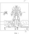
- an augmented reality scene 1 is depicted wherein a user of an AR technology sees a real-world park-like setting 1100 featuring people, trees, buildings in the background, and a concrete platform 1120.
- the user of the AR technology also perceives that he "sees" a robot statue 1110 standing upon the real-world platform 1120, and a cartoon-like avatar character 1130 flying by which seems to be a personification of a bumble bee, even though these elements 1130, 1110 do not exist in the real world.
- the human visual perception system is complex, it is challenging to produce a VR or AR technology that facilitates a comfortable, natural-feeling, rich presentation of virtual image elements amongst other virtual or real-world imagery elements.
- Known virtual and augmented reality systems are known from documents US2014/140654 and WO2010/067114 .
- VR and AR experiences can be provided by display systems having displays in which images corresponding to a plurality of depth planes are provided to a viewer.
- the images may be different for each depth plane (e.g. provide slightly different presentations of a scene or object) and may be separately focused by the viewer's eyes, thereby helping to provide the user with depth cues based on the accommodation of the eye required to bring into focus different image features for the scene located on different depth plane and/or based on observing different image features on different depth planes being out of focus.
- depth cues provide credible perceptions of depth.
- a full color image may be formed for the various depth planes by overlaying component images that each have a particular component color. For example, red, green, and blue images may each be outputted to form each full color image. As a result, each depth plane may have multiple component color images associated with it. As disclosed herein, the component color images may be outputted using waveguides that incouple light containing image information, distribute the incoupled light across the waveguides, and then outcouple light towards a viewer.
- Light may be incoupled to the waveguide using incoupling optical elements, such as diffractive elements, and then outcoupled out of the waveguide using outcoupling optical elements, which may also be diffractive elements.
- incoupling optical elements such as diffractive elements
- outcoupling optical elements which may also be diffractive elements.
- a pair of incoupling and outcoupling optical elements may be used.
- Such an arrangement can degrade image quality.
- such optical elements typically most efficiently deflect a particular design wavelength and, undesirably, a full color image formed by red, green, and blue component images fed through such a system may exhibit significant cropping and mis-focusing depending on wavelength (e.g., cropping and mis-focusing may occur for non-design wavelength channels).
- crosstalk, or ghosting may be caused by such the incoupling and outcoupling optical elements.
- a diffractive optical element optimized for one wavelength can cause ghost-like images to be formed when impinged upon by light of other wavelengths.
- a diffractive optical element that is designed to place a green image on a depth plane 1 meter from the viewer may place blue and red images on depth planes closer or farther than a meter. This crosstalk between depth planes can undermine the viewer's perception of depth and reduce image clarity.
- color balance may be adversely impacted by the tendency of incoupling and outcoupling optical elements such as diffractive optical elements to deflect some amount of light even at wavelengths that the optical elements are not specifically designed to deflect.
- incoupling and outcoupling optical elements such as diffractive optical elements to deflect some amount of light even at wavelengths that the optical elements are not specifically designed to deflect.
- color accuracy in the full color image and the range of colors that are available may be dependent on the ability to precisely regulate the amount of light of the component colors that reaches the viewer.
- Crosstalk between the different component color images may be undesirable.
- a full color image may be formed using component red, green, and blue images.
- a red component color image, formed using red-colored light, that also includes unintended green light or blue light is undesirable for, among other things, undermining the ability to precisely regulate the amount of green or blue light that makes up the final full color image. This can reduce the color accuracy of the full color image and also reduce the range of colors that are generated, since the ability to precisely and finely regulate proportions of the different colors of light is diminished by the crosstalk. Stated another way, the full color image may be of a higher quality when the component color images are each formed with light of a "pure" component color, rather than a "dirty" component color that include a range of other unintended colors.
- various embodiments disclosed herein provide low levels of cross-talk and unintended outcoupling behavior.
- various architectures are provided for selectively outputting light of different wavelengths with low levels of crosstalk.
- light is incoupled into a waveguide and deflected to propagate in different directions, depending on wavelength.
- the incoupled light is then outcoupled by one or more outcoupling optical elements that selectively outcouple light based on the direction of propagation of the light.
- color filters are provided between a waveguide and the one or more outcoupling elements on the surface of the waveguide. The color filters limit the wavelengths of light that interact with and are outcoupled by the one or more outcoupling elements.
- a different waveguide is provided for each range of wavelengths or colors to be outputted.
- One or more incoupling optical elements selectively incouple light of the appropriate range of wavelengths into a corresponding waveguide, from which the light is outcoupled.
- the waveguides may form direct view display devices or near-eye display devices, with the waveguides configured to receive input image information and generate an output image based on the input image information. These devices may be wearable and constitute eyewear.
- the input image information received by the waveguides can be encoded in multiplexed light streams of different wavelengths (e.g., red, green and blue light) which are incoupled into one or more waveguides.
- the incoupled light can be outcoupled (or outputted) from the waveguide by one or more outcoupling optical elements.
- the one or more outcoupling optical elements can include diffractive structures, such as, for example, an analog surface relief grating (ASR), binary surface relief structures (BSR), Volume Holographic Optical Elements (VHOE), Digital Surface Relief structures and/or volume phase holographic material (e.g., holograms recorded in volume phase holographic material), or a switchable diffractive optical element (e.g., Polymer Dispersed Liquid Crystal (PDLC) grating).
- ASR analog surface relief grating
- BSR binary surface relief structures
- VHOE Volume Holographic Optical Elements
- Digital Surface Relief structures and/or volume phase holographic material e.g., holograms recorded in volume phase holographic material
- PDLC Polymer Dispersed Liquid Crystal
- These structures may additively build functionality (e.g., one functionality may be a selectively for deflecting light of a particular wavelength or range of wavelengths, and another functionality may be a selectivity for deflecting light of another wavelength or range of wavelengths) through successive fabrication steps (e.g., in which a structure with one functionality is built on top of a structure with another functionality).
- Various embodiments described herein can include one or more gratings (e.g., linear grooves) that are configured such that light propagating along a direction substantially parallel to the grating is not sufficiently deflected from its path such that it is coupled out of the waveguide.
- light propagating along a direction that is at an angle with respect to the grating e.g., perpendicular to the grooves
- the waveguide includes one or more incoupling optical elements that can redirect light at different directions that are compatible with the orientation of the corresponding diffractive structures.
- Various embodiments described herein can include optical filters that transmit specific wavelengths of light.
- the filters can limit the wavelengths of light that interact with or impinge on the one or more outcoupling optical elements, thereby reducing the likelihood of the outcoupling of light of unintended wavelengths.
- embodiments disclosed herein may provide one or more of the following advantages.
- the outcoupling of light of unintended wavelengths may be reduced, thereby reducing the occurrence of ghosting, as discussed above. This reduction or elimination of ghosting can improve image clarity.
- the reduction in the outcoupling of light if unintended wavelengths can increase the perceived color quality of images formed using the light.
- the ability to specifically outcouple a desired wavelength or range of wavelengths of light can provide images with a high degree of color accuracy and precision.
- the range of colors that may be displayed may be increased, since a high degree of control over the outcoupling of individual wavelengths of light may provide a high degree of control over the ultimate proportions of particular wavelengths of light in a final full color image.
- the ability to precisely control proportions of different wavelengths of light can increase the number of repeatable combination of component colors possible, thereby increasing the number of colors (from mixtures of the component colors) that may be displayed.
- multiple wavelengths or colors of light may be outcoupled from the same waveguide, which can have advantages for improving manufacturability and yield and reducing device costs by, for example, reducing the number of parts utilized in a display system, thereby reducing the structural and electrical complexity of the display system.
- Embodiments disclosed herein may be implemented as display systems generally.
- the display systems take the form of eyewear (e.g., they are wearable), which may advantageously provide a more immersive VR or AR experience.
- displays containing waveguides for displaying multiple depth planes e.g. a stack of waveguides (one waveguide or set of waveguides for each depth plane), may be configured to be worn positioned in front of the eyes of a user, or viewer.
- multiple waveguides e.g. two stacks of waveguides, one for each eye of a viewer, may be utilized to provide different images to each eye.
- the microphone is configured to allow the user to provide inputs or commands to the system 80 (e.g., the selection of voice menu commands, natural language questions, etc.) and/or may allow audio communication with other persons (e.g., with other users of similar display systems).
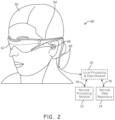
- the display 62 is operatively coupled 68, such as by a wired lead or wireless connectivity, to a local data processing module 70 which may be mounted in a variety of configurations, such as fixedly attached to the frame 64, fixedly attached to a helmet or hat worn by the user, embedded in headphones, or otherwise removably attached to the user 60 (e.g., in a backpack-style configuration, in a belt-coupling style configuration).
- the local processing and data module 70 may comprise a hardware processor, as well as digital memory, such as non-volatile memory (e.g., flash memory or hard disk drives), both of which may be utilized to assist in the processing, caching, and storage of data.
- the data include data a) captured from sensors (which may be, e.g., operatively coupled to the frame 64 or otherwise attached to the user 60), such as image capture devices (such as cameras), microphones, inertial measurement units, accelerometers, compasses, GPS units, radio devices, and/or gyros; and/or b) acquired and/or processed using remote processing module 72 and/or remote data repository 74, possibly for passage to the display 62 after such processing or retrieval.
- sensors which may be, e.g., operatively coupled to the frame 64 or otherwise attached to the user 60
- image capture devices such as cameras
- microphones such as cameras
- inertial measurement units such as cameras
- accelerometers compasses
- GPS units GPS units
- radio devices radio devices
- the local processing and data module 70 may be operatively coupled by communication links 76, 78, such as via a wired or wireless communication links, to the remote processing module 72 and remote data repository 74 such that these remote modules 72, 74 are operatively coupled to each other and available as resources to the local processing and data module 70.
- the location processing and data module 70 may include one or more of the image capture devices, microphones, inertial measurement units, accelerometers, compasses, GPS units, radio devices, and/or gyros. In some other embodiments, one or more of these sensors may be attached to the frame 64, or may be stand alone structures that communicate with the location processing and data module 70 by wired or wireless communication pathways.
- the remote processing module 72 may comprise one or more processors configured to analyze and process data and/or image information.
- the remote data repository 74 may comprise a digital data storage facility, which may be available through the internet or other networking configuration in a "cloud" resource configuration. In some embodiments, all data is stored and all computations are performed in the local processing and data module, allowing fully autonomous use from a remote module.
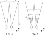
- FIG. 3 illustrates a conventional display system for simulating three-dimensional imagery for a user.
- the images 5, 7 are spaced from the eyes 4, 6 by a distance 10 along an optical or z-axis parallel to the line of sight of the viewer.
- the images 5, 7 are flat and the eyes 4, 6 may focus on the images by assuming a single accommodated state.
- Such systems rely on the human visual system to combine the images 5, 7 to provide a perception of depth for the combined image.
- vergence movements i.e., rolling movements of the pupils toward or away from each other to converge the lines of sight of the eyes to fixate upon an object
- vergence movements i.e., rolling movements of the pupils toward or away from each other to converge the lines of sight of the eyes to fixate upon an object
- vergence movements of the two eyes relative to each other are closely associated with focusing (or "accommodation") of the lenses of the eyes.
- Figure 4 illustrates aspects of an approach for simulating three-dimensional imagery using multiple depth planes.
- objects at various distances from eyes 4, 6 on the z-axis are accommodated by the eyes 4, 6 so that those objects are in focus.
- the eyes (4 and 6) assume particular accommodated states to bring into focus objects at different distances along the z-axis. Consequently, a particular accommodated state may be said to be associated with a particular one of depth planes 14, with has an associated focal distance, such that objects or parts of objects in a particular depth plane are in focus when the eye is in the accommodated state for that depth plane.
- three-dimensional imagery may be simulated by providing different presentations of an image for each of the eyes 4, 6, and also by providing different presentations of the image corresponding to each of the depth planes. While shown as being separate for clarity of illustration, it will be appreciated that the fields of view of the eyes 4, 6 may overlap, for example, as distance along the z-axis increases. Additionally, while shown as flat for ease of illustration, it will be appreciated that the contours of a depth plane may be curved in physical space, such that all features in a depth plane are in focus with the eye in a particular accommodated state.
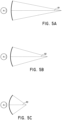
- the distance between an object and the eye 4 or 6 can also change the amount of divergence of light from that object, as viewed by that eye.
- Figures 5A-5C illustrates relationships between distance and the divergence of light rays.
- the distance between the object and the eye 4 is represented by, in order of decreasing distance, R1, R2, and R3.
- the light rays become more divergent as distance to the object decreases.
- the light rays become more collimated.
- the light field produced by a point has a spherical wavefront curvature, which is a function of how far away the point is from the eye of the user.
- the curvature increases with decreasing distance between the object and the eye 4. Consequently, at different depth planes, the degree of divergence of light rays is also different, with the degree of divergence increasing with decreasing distance between depth planes and the viewer's eye 4.
- eye 4 While only a single eye 4 is illustrated for clarity of illustration in Figures 5A-5C and other figures herein, it will be appreciated that the discussions regarding eye 4 may be applied to both eyes 4 and 6 of a viewer.
- the human eye typically can interpret a finite number of depth planes to provide depth perception. Consequently, a highly believable simulation of perceived depth may be achieved by providing, to the eye, different presentations of an image corresponding to each of these limited number of depth planes.
- the different presentations may be separately focused by the viewer's eyes, thereby helping to provide the user with depth cues based on the accommodation of the eye required to bring into focus different image features for the scene located on different depth plane and/or based on observing different image features on different depth planes being out of focus.
- FIG. 6 illustrates an example of a waveguide stack for outputting image information to a user.
- a display system 1000 includes a stack of waveguides, or stacked waveguide assembly, 178 that may be utilized to provide three-dimensional perception to the eye/brain using a plurality of waveguides 182, 184, 186, 188, 190.
- the display system 1000 is the system 80 of Figure 2 , with Figure 6 schematically showing some parts of that system 80 in greater detail.
- the waveguide assembly 178 may be part of the display 62 of Figure 2 .
- the waveguide assembly 178 may also include a plurality of features 198, 196, 194, 192 between the waveguides.
- the features 198, 196, 194, 192 may be lens.
- the waveguides 182, 184, 186, 188, 190 and/or the plurality of lenses 198, 196, 194, 192 may be configured to send image information to the eye with various levels of wavefront curvature or light ray divergence. Each waveguide level may be associated with a particular depth plane and may be configured to output image information corresponding to that depth plane.
- Image injection devices 200, 202, 204, 206, 208 may function as a source of light for the waveguides and may be utilized to inject image information into the waveguides 182, 184, 186, 188, 190, each of which may be configured, as described herein, to distribute incoming light across each respective waveguide, for output toward the eye 4.
- the input surfaces 382, 384, 386, 388, 390 may be an edge of a corresponding waveguide, or may be part of a major surface of the corresponding waveguide (that is, one of the waveguide surfaces directly facing the world 144 or the viewer's eye 4).
- a single beam of light e.g. a collimated beam
- a single one of the image injection devices 200, 202, 204, 206, 208 may be associated with and inject light into a plurality (e.g., three) of the waveguides 182, 184, 186, 188, 190.
- the image injection devices 200, 202, 204, 206, 208 are discrete displays that each produce image information for injection into a corresponding waveguide 182, 184, 186, 188, 190, respectively.
- the image injection devices 200, 202, 204, 206, 208 are the output ends of a single multiplexed display which may, e.g., pipe image information via one or more optical conduits (such as fiber optic cables) to each of the image injection devices 200, 202, 204, 206, 208.
- the image information provided by the image injection devices 200, 202, 204, 206, 208 may include light of different wavelengths, or colors (e.g., different component colors, as discussed herein).
- a controller 210 controls the operation of the stacked waveguide assembly 178 and the image injection devices 200, 202, 204, 206, 208.
- the controller 210 is part of the local data processing module 70.
- the controller 210 includes programming (e.g., instructions in a non-transitory medium) that regulates the timing and provision of image information to the waveguides 182, 184, 186, 188, 190 according to, e.g., any of the various schemes disclosed herein.
- the controller may be a single integral device, or a distributed system connected by wired or wireless communication channels.
- the controller 210 may be part of the processing modules 70 or 72 ( Figure 1 ) in some embodiments.
- the waveguides 182, 184, 186, 188, 190 may be configured to propagate light within each respective waveguide by total internal reflection (TIR).
- the waveguides 182, 184, 186, 188, 190 may each be planar or have another shape (e.g., curved), with major top and bottom surfaces and edges extending between those major top and bottom surfaces.
- the waveguides 182, 184, 186, 188, 190 may each include one or more outcoupling optical elements 282, 284, 286, 288, 290 that are configured to extract light out of a waveguide by redirecting the light, propagating within each respective waveguide, out of the waveguide to output image information to the eye 4.
- Extracted light may also be referred to as outcoupled light and the one or more outcoupling optical elements light may also be referred to light extracting optical elements.
- An extracted beam of light is outputted by the waveguide at locations at which the light propagating in the waveguide strikes a light extracting optical element.
- Some or all of the one or more outcoupling optical elements 282, 284, 286, 288, 290 may, for example, can be one or more gratings, including diffractive optical features, as discussed further herein.
- the one or more outcoupling optical elements 282, 284, 286, 288, 290 may be disposed at the top and/or bottom major surfaces, and/or may be disposed directly in the volume of the waveguides 182, 184, 186, 188, 190, as discussed further herein.
- the one or more outcoupling optical elements 282, 284, 286, 288, 290 may be formed in a layer of material that is attached to a transparent substrate to form the waveguides 182, 184, 186, 188, 190.
- the waveguides 182, 184, 186, 188, 190 may be a monolithic piece of material and the one or more outcoupling optical elements 282, 284, 286, 288, 290 may be formed on a surface and/or in the interior of that piece of material.
- each waveguide 182, 184, 186, 188, 190 is configured to output light to form an image corresponding to a particular depth plane.
- the waveguide 182 nearest the eye may be configured to deliver collimated light, as injected into such waveguide 182, to the eye 4.
- the collimated light may be representative of the optical infinity focal plane.
- the next waveguide up 184 may be configured to send out collimated light which passes through the first lens 192 (e.g., a negative lens) before it can reach the eye 4; such first lens 192 may be configured to create a slight convex wavefront curvature so that the eye/brain interprets light coming from that next waveguide up 184 as coming from a first focal plane closer inward toward the eye 4 from optical infinity.
- first lens 192 e.g., a negative lens
- the third up waveguide 186 passes its output light through both the first 192 and second 194 lenses before reaching the eye 4; the combined optical power of the first 192 and second 194 lenses may be configured to create another incremental amount of wavefront curvature so that the eye/brain interprets light coming from the third waveguide 186 as coming from a second focal plane that is even closer inward toward the person from optical infinity than was light from the next waveguide up 184. Other ways of producing these perceived colors may be possible.
- the other waveguide layers 188, 190 and lenses 196, 198 are similarly configured, with the highest waveguide 190 in the stack sending its output through all of the lenses between it and the eye for an aggregate focal power representative of the closest focal plane to the person.
- a compensating lens layer 180 may be disposed at the top of the stack to compensate for the aggregate power of the lens stack 198, 196, 194, 192 below.
- Such a configuration provides as many perceived focal planes as there are available waveguide/lens pairings.
- Both the one or more outcoupling optical elements of the waveguides and the focusing aspects of the lenses may be static (i.e., not dynamic or electro-active). In some alternative embodiments, either or both may be dynamic using electro-active features.
- two or more of the waveguides 182, 184, 186, 188, 190 may have the same associated depth plane.
- multiple waveguides 182, 184, 186, 188, 190 may be configured to output images set to the same depth plane, or multiple subsets of the waveguides 182, 184, 186, 188, 190 may be configured to output images set to the same plurality of depth planes, with one set for each depth plane. This can provide advantages for forming a tiled image to provide an expanded field of view at those depth planes.
- the one or more outcoupling optical elements 282, 284, 286, 288, 290 may be configured to both redirect light out of their respective waveguides and to output this light with the appropriate amount of divergence or collimation for a particular depth plane associated with the waveguide.
- waveguides having different associated depth planes may have different configurations of one or more outcoupling optical elements 282, 284, 286, 288, 290, which output light with a different amount of divergence depending on the associated depth plane.
- the features 198, 196, 194, 192 may not be lenses; rather, they may simply be spacers (e.g., cladding layers and/or structures for forming air gaps).
- the one or more outcoupling optical elements 282, 284, 286, 288, 290 are diffractive features that form a diffraction pattern, or "diffractive optical element" (also referred to herein as a "DOE").
- the DOE's have a sufficiently low diffraction efficiency so that only a portion of the light of the beam is deflected away toward the eye 4 with each intersection of the DOE, while the rest continues to move through a waveguide via total internal reflection.
- the light carrying the image information is thus divided into a number of related exit beams that exit the waveguide at a multiplicity of locations and the result is a fairly uniform pattern of exit emission toward the eye 4 for this particular collimated beam bouncing around within a waveguide.
- one or more DOEs may be switchable between "on” states in which they actively diffract, and "off” states in which they do not significantly diffract.
- a switchable DOE may comprise a layer of polymer dispersed liquid crystal, in which microdroplets comprise a diffraction pattern in a host medium, and the refractive index of the microdroplets can be switched to substantially match the refractive index of the host material (in which case the pattern does not appreciably diffract incident light) or the microdroplet can be switched to an index that does not match that of the host medium (in which case the pattern actively diffracts incident light).
- Figure 7 shows an example of exit beams outputted by a waveguide.
- One waveguide is illustrated, but it will be appreciated that other waveguides in the waveguide assembly 178 may function similarly, where the waveguide assembly 178 includes multiple waveguides.
- Light 400 is injected into the waveguide 182 at the input edge 382 of the waveguide 182 and propagates within the waveguide 182 by TIR. At points where the light 400 impinges on the DOE 282, a portion of the light exits the waveguide as exit beams 402.
- the exit beams 402 are illustrated as substantially parallel but, as discussed herein, they may also be redirected to propagate to the eye 4 at an angle (e.g., forming divergent exit beams), depending on the depth plane associated with the waveguide 182.
- substantially parallel exit beams may be indicative of a waveguide with one or more outcoupling optical elements that outcouple light to form images that appear to be set on a depth plane at a large distance (e.g., optical infinity) from the eye 4.
- Other waveguides or other sets of outcoupling optical elements may output an exit beam pattern that is more divergent, which would require the eye 4 to accommodate to a closer distance to bring it into focus on the retina and would be interpreted by the brain as light from a distance closer to the eye 4 than optical infinity.
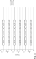
- FIG. 8 schematically illustrates an example of a stacked waveguide assembly in which each depth plane includes images formed using multiple different component colors.
- a full color image may be formed at each depth plane by overlaying images in each of the component colors, e.g., three or more component colors.
- the illustrated embodiment shows depth planes 14a - 14f, although more or fewer depths are also contemplated.
- Each depth plane may have three component color images associated with it: a first image of a first color, G; a second image of a second color, R; and a third image of a third color, B.
- Different depth planes are indicated in the figure by different numbers for diopters following the letters G, R, and B. Just as examples, the numbers following each of these letters indicate diopters (1/m), or distance of the depth plane from a viewer, and each box in the figures represents an individual component color image.
- each component color may be outputted by a single dedicated waveguide and, consequently, each depth plane may have multiple waveguides associated with it.
- each box in the figures including the letters G, R, or B may be understood to represent an individual waveguide, and three waveguides may be provided per depth plane where three component color images are provided per depth plane. While the waveguides associated with each depth plane are shown adjacent to one another in this schematic drawing for ease of description, it will be appreciated that, in a physical device, the waveguides may all be arranged in a stack with one waveguide per level. In some other embodiments, multiple component colors may be outputted by the same waveguide, such that, e.g., only a single waveguide may be provided per depth plane.
- G is the color green
- R is the color red
- B is the color blue.
- other colors including magenta and cyan, may be used in addition to or may replace one or more of red, green, or blue.
- references to a given color of light throughout this disclosure will be understood to encompass light of one or more wavelengths within a range of wavelengths of light that are perceived by a viewer as being of that given color.
- red light may include light of one or more wavelengths in the range of about 620-780 nm
- green light may include light of one or more wavelengths in the range of about 492-577 nm
- blue light may include light of one or more wavelengths in the range of about 435-493 nm.
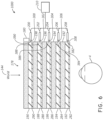
- the waveguide 905 can be planar, having a first major surface 905a, a second major surface 905b opposite the first major surface 905b and edges extending between those first and the second major surfaces 905a and 905b.
- the first and the second major surfaces 905a and 905b can extend in the x-y plane and a surface normal that intersects the first and the second major surfaces 905 and 905b can be oriented along the z-axis.
- the waveguide 905 can comprise an optical grade material that is configured to be transmissive to wavelengths in the visible spectrum or wavelengths corresponding to the component colors to be outputted by the waveguide 905.
- the waveguides disclose herein, including the waveguide 905 can be monolithic piece of material.
- the first and the second major surfaces 905a and 905b and the space between the two major surfaces 905a and 905b comprise the same material.
- the waveguides may include multiple layers of material.
- the space between the first and the second major surfaces 905a and 905b can include materials having a first refractive index and the space between the first and the second major surfaces 905a and 905b can include materials can include materials that have a different refractive index.
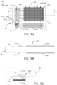
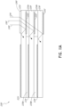
- the one or more outcoupling optical coupling elements can include a first optical coupling element 909a and a second optical coupling element 909b, as depicted in Figure 9B , which schematically illustrates an example of a cross-sectional view of the display device 900 along the axis A-A'.
- the first and the second outcoupling optical elements 909a and 909b can be combined together to form a single outcoupling optical element, e.g., on the same major surface or on both the first second major surfaces 905a and 905b.
- the incoupling optical element 907 is configured to incouple incident light of a first plurality of wavelengths such that they propagate through the waveguide 905 by total internal reflection along a first direction and incouple light incident of one or more second wavelengths such that they propagate through the waveguide 905 by total internal reflection along a second direction.
- the first and the second directions extend in a plane coplanar with the first or the second major surface 905a or 905b of the waveguide 905.
- Figure 9A when the waveguide 905 is viewed along a direction parallel to the surface normal to the first or the second major surface 905a or 905b (e.g., as seen in a top-down view when the waveguide 905 is oriented with the first major surface 905a pointing upwards), the first direction can be parallel to the y-axis and the second direction can be parallel to the x-axis. Accordingly, Figure 9A illustrates that the first and the second directions are orthogonal to each other in a plane coplanar with the first or the second major surface 905a or 905b.
- first and the second directions can be oriented with respect to each other at angles different from 90-degrees when viewed along a direction parallel to the surface normal to the first or the second major surface 905a or 905b.
- first and the second directions can be oriented with respect to each other at angles between about 60 degrees and 120 degrees, between about 70 degrees and about 110 degrees, between about 80 degrees and about 100 degrees, between about 85 degrees and about 95 degrees, or angles therebetween.
- the angle is chosen such that light propagating in the first direction is deflected at high efficiency by one of the outcoupling elements and low efficiency by the other of the outcoupling optical elements, and light propagating in the second direction is deflected at high efficiency by the former outcoupling element and low efficiency by the latter outcoupling optical element.
- the one or more second wavelengths can be different from the first plurality of wavelengths.
- light having multiple component colors e.g., red, green, blue
- the first outcoupling optical element 909a is configured to redirect, out of the waveguide 905, light of the first plurality of wavelengths that propagate through the waveguide 905 along the first direction
- the second outcoupling optical element 909b is configured to redirect, out of the waveguide 905, light of the one or more second wavelengths that propagate through the waveguide 905 along the second direction.
- the first plurality of wavelengths encompasses light of two component colors, e.g., red and blue; and the one or more second wavelengths encompasses light of a third component color, e.g., green.
- the two component colors have a greater difference between the wavelengths of those two component colors than the difference between either of the two component colors and the wavelength of the third color, which can facilitate reductions in crosstalk.
- the first outcoupling optical element 909a includes ASRs, which deflect light of each of the two component colors.
- the waveguide 905 may be part of the stack of waveguides in the display system 1000 ( Figure 6 ).
- the waveguide 905 may correspond to one of the waveguides 182, 184, 186, 188, 190
- the outcoupling optical elements 909a and 909b may correspond to the outcoupling optical elements 282, 284, 286, 288, 290 of Figure 6 .
- the incoupling optical element 907 can be a wavelength selective optical component that is configured to deflect different wavelengths of light such that they propagate along different directions through the waveguide 905 by TIR.
- the incoupling optical element 907 can comprise a first set of incoupling optical elements configured to interact with light at the first plurality of wavelengths and a second set of incoupling optical elements configured to interact with light at the one or more second wavelengths.
- the elements forming the incoupling optical element 907 can include one or more optical prism, or optical components including one or more diffractive elements and/or refractive elements.
- the incoupling optical element 907 can include one or more gratings that can interact with light at one or more wavelengths. For example, if the incident light comprises light at red, green and blue wavelengths, then the incoupling optical element 907 can include a grating that interacts with all three wavelengths or a first grating that interacts with red light, a second grating that interact with green light and a third grating that interacts with blue light. In some embodiments, the first grating that interacts with red light and the third grating that interacts with blue light can be combined in a single grating structure.
- the one or more gratings included in the incoupling optical element 907 can include one or more of analog surface relief grating (ASR), Binary surface relief structures (BSR), Volume Holographic Optical Elements (VHOE), Digital Surface Relief structures and/or volume phase holographic material (e.g., holograms recorded in volume phase holographic material), or switchable diffractive optical element (e.g., Polymer Dispersed Liquid Crystal (PDLC) grating).
- ASR analog surface relief grating
- BSR Binary surface relief structures
- VHOE Volume Holographic Optical Elements
- Digital Surface Relief structures and/or volume phase holographic material e.g., holograms recorded in volume phase holographic material
- switchable diffractive optical element e.g., Polymer Dispersed Liquid Crystal (PDLC) grating
- Other types of grating, holograms, and/or diffractive optical elements, providing the functionality disclosed herein, may also be used.
- the one or more gratings are configured to direct incident light in the first plurality of wavelengths - represented by rays 903i1 and 903i2 - such that the light in the first plurality of wavelengths propagates through the waveguide 905 along the first direction (e.g., along a direction parallel to the y-axis) and direct incident light at the one or more second wavelengths - represented by ray 903i3 - such that light at the one or more second wavelengths propagates through the waveguide along the second direction (e.g., along a direction parallel to the x-axis).
- the one or more gratings are configured to couple light into the waveguide 905 by deflecting light incident from a direction forward of the first major surface 905a or rearward of the second major surface 905b at appropriate angles that results in the incident light to undergo TIR in the waveguide 905.
- the incoupling optical element 907 can include a reflective grating and/or transmissive grating. In some embodiments including one or more reflective gratings, incoming light is incident on the grating from within the waveguide 905 and is diffracted along the first or the second directions of the waveguide 905.
- one or more wavelength selective filters 913a and 913b may be integrated with or disposed adjacent to the incoupling optical elements 907.
- the one or more wavelength selective filters 913a and 913b may be configured to filter out some portion of light at the one or more second wavelengths that may be propagating along the first direction and some portion of light at the first plurality of wavelengths that may be propagating along the second direction respectively.
- the wavelength selective filters 913a and 913b can be absorptive filters.
- the wavelength selective filters 1013a and 1013b can be color band absorbers.
- the wavelength selective filters 913a and 913b can include a dichroic filter.
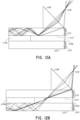
- Figure 9C illustrates an example of a dichroic wavelength selective filter 913b and depicts the operation of that dichroic wavelength selective filter.
- the dichroic wavelength selective filter 913b (or 913a) is configured to pass or transmit light at the first plurality of wavelengths (or the one or more second wavelengths) that is propagating along the second direction (or the first direction) by TIR and reflect the one or more second wavelengths (or the first plurality of wavelengths) propagating along the second direction (or the first direction) by TIR.
- the light that is passed through the dichroic wavelength selective filter 913b (or 913a) is absorbed by an absorber 915b that is integrated with or disposed adjacent to the dichroic wavelength selective filter 913b (or 913a).
- the incoupling optical element 907 either individually or in combination with the wavelength selective filter 913b (or 913a) and absorber 915b can increase the degree of isolation between incoupled light at the first plurality of wavelengths propagating through the waveguide 905 along the first direction and incoupled light at the one or more second wavelengths propagating through the waveguide 905 along the second direction.
- the incoupling optical element 907 either individually or in combination with the wavelength selective filter 913b (or 913a) and absorber 915b can, by limiting the amount of light of different wavelengths propagating through the waveguide 905, reduce crosstalk between incoupled light at the first plurality of wavelengths propagating through the waveguide 905 along the first direction and incoupled light at the one or more second wavelengths propagating through the waveguide 905 along the second direction.
- Reducing crosstalk between incoupled light at the first plurality of wavelengths propagating through the waveguide 905 along the first direction and incoupled light at the one or more second wavelengths propagating through the waveguide 905 along the second direction can be advantageous in improving the outcoupling efficiency of the first and the second outcoupling optical elements 909a and 909b and also improve the quality of the color image generated by the outcoupled light.
- the incoupling optical element 907 can be disposed adjacent the first or the second major surface 905a or 905b of the waveguide 905. In various embodiments, the incoupling optical element 907 can be disposed adjacent a corner of the waveguide 905. The incoupling optical element 907 can be distinct from the waveguide 905. Alternately, the incoupling optical element 907 can be integrated with one or both of the first or the second major surface 905a or 905b of the waveguide 905. In various embodiments, the incoupling optical element 907 and the waveguide 905 can be monolithically integrated. In various embodiments, the incoupling optical element 907 can be formed in a portion of the waveguide 905.
- the one or more gratings may be formed in a portion of the first and/or the second major surface 905a and/or 905b of the waveguide 905.
- the incoupling optical element 907 may be disposed in a layer of optical transmissive material which is disposed adjacent to the first and/or the second major surface 905a and/or 905b of the waveguide 905.
- the incoupling optical element 907 may be disposed in the bulk of waveguide 905.
- the display device 900 can include first light distributing element 911a disposed in the light path of the incoupled light at the first plurality of wavelengths propagating through the waveguide 905 along the first direction.
- the display device 900 can also include second light distributing element 911b disposed in the light path of the incoupled light at the one or more second wavelengths propagating through the waveguide 905 along the second direction.
- the first and the second light distributing elements 911a and 911b can be configured to distribute light of the first plurality of wavelengths and of the one or more second wavelengths along the first and the second direction respectively.
- the first and the second light distributing elements 911a and 911b can be configured to elongate light (e.g., spread light across the length) of the first plurality of wavelengths and of the one or more second wavelengths along the first and second directions respectively.
- the first and second light distributing elements 911a and 911b can be referred to as pupil expanders or orthogonal pupil expanders (OPEs) since by virtue of distributing light along the first and the second directions, they can advantageously increase the spot size of a first light beam including light at the first plurality of wavelengths and a second light beam including light at the one or more second wavelengths.
- the first and second light distributing elements 911a and 911b can also be useful to increase the size of the exit pupil of the display device 900.
- the first and the second light distributing elements 911a and 911b can include one or more gratings that are configured to direct light propagating along the first and the second direction respectively towards the first and the second outcoupling optical elements 909a and 909b.
- the one or more gratings can be configured, for example, to have a size (e.g., groove depth or groove height, shape, spacing, and/or periodicity) and an orientation that is configured to interact with light of the first plurality of wavelengths propagating along the first direction or light of the one or more second wavelengths propagating along the second direction.
- the first light distributing element 911a can include a grating that is configured to interact with red and blue light or a first grating that interacts with red light and a second grating that interacts with blue light.
- the second light distributing element 911b can include a grating that is configured to interact with green light.
- the first and the second light distributing elements 911a and 911b are each configured to redirect a portion of the light that impinges on the gratings at as the light every bounce as the incoupled light at the first plurality of wavelengths and at the one or more second wavelengths propagates through the waveguide by TIR.
- the first and the second light distributing elements 911a and 911b can divide the first and the second light beams propagating along the first and the second directions into multiple related beams that are redirected towards the first and the second outcoupling optical elements 909a and 909b.
- the multiple related beams can be copies of each other.
- the first and the second light distributing elements 911a and 911b can be configured to uniformly or substantially uniformly illuminate a larger area of the first and the second outcoupling optical elements 909a and 909b which can result in a fairly uniform pattern of exit emission from the waveguide 905.
- the first and the second light distributing elements 911a and 911b can be configured to redirect light incident at a single wavelength or multiple wavelengths within a wavelength range.
- the one or more gratings included in the first and the second light distributing elements 911a and 911b can include one or more of an analog surface relief grating (ASR), Binary surface relief structures (BSR), a Volume Holographic Optical Element (VHOE), Digital Surface Relief structures and/or volume phase holographic material, or a switchable diffractive optical element (e.g., Polymer Dispersed Liquid Crystal (PDLC) grating).
- ASR analog surface relief grating
- BSR Binary surface relief structures
- VHOE Volume Holographic Optical Element
- PDLC Polymer Dispersed Liquid Crystal
- Other types of gratings, holograms, and/or diffractive optical elements, configured to provide the functionality disclosed herein, may also be used.
- the first and the second light distributing elements 911a and 911b can be disposed adjacent the first or the second major surface 905a or 905b of the waveguide 905.
- the first and the second light distributing elements 911a and 911b can be disposed such that they are spaced apart from the first and the outcoupling optical elements 909a and 909b, although the first and the second light distributing elements 911a and 911b need not be so configured in some embodiments.
- the first and the second light distributing elements 911a and 911b can be integrated with one or both of the first or the second major surface 905a or 905b of the waveguide 905.
- the first and the second light distributing elements 911a and 911b and the waveguide 905 can be monolithically integrated.
- the first and the second light distributing elements 911a and 911b can be formed in a portion of the first and/or the second major surface 905a and/or 905b of the waveguide 905.
- the first and the second light distributing elements 911a and 911b may be disposed in one or more layers of optical transmissive material which are disposed adjacent to the first and/or the second major surface 905a and/or 905b of the waveguide 905.
- the first and the second light distributing elements 911a and 911b may be disposed in the bulk of waveguide 905.
- the first outcoupling optical element 909a and the second outcoupling optical element 909b are configured to redirect incoupled light that is incident on them out of the plane of the waveguide 905.
- the first and the second outcoupling elements 909a and 909b are configured to redirect the incoupled light that is incident on the first and the second outcoupling elements 909a and 909b toward the viewer (e.g., eye 4, Figure 7 ) at appropriate angles to ensure proper overlay of light at different wavelengths such that the viewer can perceive a color image of good visual quality.
- the first and the second outcoupling optical elements 909a and 909b can have an optical power that provides a divergence to the light that exits through the waveguide 905 such that the image formed by the light that exits through the waveguide 905 appears to originate from a certain depth. Accordingly, the waveguide 905 may be considered to have an associated depth plane that is correlated with the optical power of the first and the second outcoupling optical elements 909a and 909b.
- various embodiments of display devices can include a plurality different waveguides similar to waveguide 905 described above - including the incoupling optical element 907 and the first and the second outcoupling optical elements 909a and 909b with different optical powers - that are stacked together.
- the different waveguides can be associated with different depth planes corresponding to the different optical powers of the first and the second outcoupling optical elements 909a and 909b including therein.
- Display devices including such plurality of different waveguides stacked together can be useful to generate 3D images and, in particular, light field based 3D images.
- the first outcoupling optical element 909a and the second outcoupling optical element 909b can include one or more gratings.
- the first outcoupling element 909a can include one or more gratings that are configured to interact with light of the first plurality of wavelengths and the second outcoupling element 909b can include one or more gratings that are configured to interact with light of the one or more second wavelengths.
- the first plurality of wavelengths includes red and blue wavelengths
- the first outcoupling element 909a can include a grating structure that interacts with both red and blue light or a first grating that interacts with red light and a second grating that interacts with blue light.
- the one or more second wavelengths includes green wavelength
- the second outcoupling element 909b can include a grating that interacts with green light.
- the first and the second outcoupling elements 909a and 909b can include linear grooves that are configured such that light propagating along a direction substantially parallel to the length of grooves is not sufficiently deflected from its path such that it is couple out of the waveguide.
- light propagating along a direction that is at an angle with respect to the grooves e.g., perpendicular to the length of the grooves
- the grooves in the first outcoupling element 909a are oriented along a direction parallel or substantially parallel to the second direction such that the light at the one or more second wavelengths propagating along the second direction are not sufficiently deflected by the first outcoupling optical element 909a to be outcoupled out of the waveguide 905 and light at the first plurality of wavelengths propagating along the first direction are sufficiently deflected by the first outcoupling optical element 909a to be outcoupled out of the waveguide 905.
- the grooves in the second outcoupling element 909b are oriented along a direction parallel or substantially parallel to the first direction such that the light at the first plurality of wavelengths propagating along the first direction are not sufficiently deflected by the second outcoupling optical element 909b to be outcoupled out of the waveguide 905 and light of one or more second wavelengths propagating along the second direction is sufficiently deflected by the second outcoupling optical element 909b to be outcoupled out of the waveguide 905.
- the first outcoupling optical element 909a and the second outcoupling optical element 909b can include analog surface relief grating (ASR), Binary surface relief structures (BSR), Volume Holographic Optical Elements (VHOE), Digital Surface Relief structures and/or volume phase holographic material (e.g., holograms recorded in volume phase holographic material), or switchable diffractive optical element (e.g., Polymer Dispersed Liquid Crystal (PDLC) grating). Other types of gratings, holograms, and/or diffractive optical elements, providing the functionality disclosed herein, may also be used.
- the first and the second outcoupling optical elements 909a and 909b can be integrated as a single outcoupling optical element 909.
- a single outcoupling optical element 909 including different holograms for different wavelengths (e.g., red, green and blue) recorded on top of each other can be disposed on one of the major surfaces 905a and 905b instead of two outcoupling optical elements 909a and 909b disposed on the first and the second major surface 905a and 905b as shown in Figure 9B .
- the first outcoupling optical element 909a can be disposed on one of the first or the second major surface 905a or 905b and the second outcoupling optical element 909b can be disposed on the other major surface.
- the first and the second outcoupling optical element 909a and 909b can be formed on one or both of the first and the second major surface 905a and 905b. In various embodiments, the first and the second outcoupling element can be formed on a layer that is disposed on one of the first or the second major surface 905a or 905b.
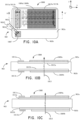
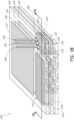
- Figure 10A schematically illustrates an example of a top view of a display device 1000 including a waveguide 905, incoupling optical element 1007, wavelength selective filters 1013a and 1013b, and first and second outcoupling optical elements 1009a and 1009b.
- Figures 10B and 10C illustrate examples of a cross-sectional view of the display device 1000 depicted in Figure 10A along the axis A-A'.
- the display device is configured such that incoming incident light of different wavelengths represented by rays 903i1, 903i2 and 903i3 are coupled into the waveguide 905 by the incoupling optical element 1007.
- the incoupling optical element 1007 can be configured to couple all wavelengths of the incident light into the waveguide 905 at appropriate angles that support propagation through the waveguide by virtue of TIR. In various embodiments, the incoupling optical element 1007 need not be configured to incouple the different wavelengths of incident light such that they propagate along different directions. Thus, in some embodiments, all the wavelengths of the incident light can be coupled into the waveguide 905 such that they propagate through the waveguide along a same direction.
- the incoupling optical element can include a plurality of gratings, such as, for example, analog surface relief grating (ASR), Binary surface relief structures (BSR), Volume Holographic Optical Elements (VHOE), Digital Surface Relief structures and/or volume phase holographic material (e.g., holograms recorded in volume phase holographic material), or switchable diffractive optical element (e.g., a Polymer Dispersed Liquid Crystal (PDLC) grating). Other types of gratings, holograms, and/or diffractive optical elements, providing the functionality disclosed herein, may also be used.
- the incoupling optical element 1007 can include one or more optical prisms, or optical components including one or more diffractive elements and/or refractive elements.
- the display device 1000 includes wavelength selective filters 1013a and 1013b, each wavelength selective filter 1013a and 1013b being associated with one of the outcoupling optical element 1009a and 1009b.
- wavelength selective filter 1013a is associated with outcoupling optical element 1009a
- wavelength selective filter 1013b is associated with outcoupling optical element 1009b.
- the wavelength selective filter 1013a includes a first rearward surface and a first forward surface opposite the first rearward surface.
- the wavelength selective filter 1013b includes a second rearward surface and a second forward surface opposite the second rearward surface.
- the wavelength selective filter 1013a can be disposed on the first major surface of the waveguide 905, in a recess, e.g., such that the first forward surface is on the same level as portions of the first major surface 905a of the waveguide 905, as illustrated in Figure 10B .
- the wavelength selective filter 1013a can be disposed such that the first rearward surface simply overlies the first major surface 905a (without being disposed in a recess) as illustrated in Figure 10C .
- the wavelength selective filter 1013b can be disposed in a recess in the second major surface of the waveguide 905, e.g., such that the second forward surface is on the same level as the second major surface 905b of the waveguide 905 as illustrated in Figure 10B .
- the wavelength selective filter 1013b can be disposed such that the second rearward surface simply underlies the second major surface 905b (without being disposed in a recess) as illustrated in Figure 10C . Light propagating in the waveguide 905 is incident on the first or the second rearward surface of the first or the second wavelength selective filter 1013a or 1013b respectively.
- the first and the second wavelength selective filter 1013a and 1013b are capable of reflecting a portion of the light transmitted through the first or the second rearward surface.
- the wavelength selective filter 1013a is configured to transmit a portion of light at a first plurality of wavelengths (e.g., light at red and blue wavelength ranges) that are propagating through the waveguide 905 by multiple reflections towards the respective outcoupling optical element 1009a that are configured to deflect the first plurality of wavelengths out of the waveguide 905.
- the wavelength selective filter 1013a is configured to reflect light at wavelengths different from the first plurality of wavelengths away from the outcoupling optical element 1009a.
- the wavelength selective filter 1013b is configured to transmit a portion of light of one or more second wavelengths (e.g., light in the green wavelength range) that are propagating through the waveguide 905 by multiple reflections towards the respective outcoupling optical element 1009b that are configured to deflect light of the one or more second wavelengths out of the waveguide 905.
- the wavelength selective filter 1013b is configured to reflect light at wavelengths different from the one or more second wavelengths away from the outcoupling optical element 1009b. In this manner, the wavelength selective filters 1013a and 1013b can reduce crosstalk between the different wavelengths of light that are coupled out of the waveguide 905 to generate the color image.
- the wavelength selective filters 1013a and 1013b can include one or more dichroic filters.
- the wavelength selective filters 1013a and 1013b can be disposed on the first and the second major surfaces 905a and 905b of the waveguide 905. Without any loss of generality, the wavelengths selective filters 1013a and 1013b can be configured to transmit light that is incident on the filters 1013a and 1013b at near normal angles.
- wavelength selective filters 1013a and 1013b when the wavelength selective filters 1013a and 1013b are disposed parallel to the first and the second major surfaces 905a and 905b, light that is incident at angles between, e.g., about 0 degrees and about 20 degrees with respect to a normal to the first and the second major surfaces 905a and 905b can be transmitted through the wavelength selective filters 1013a and 1013b. Accordingly, the wavelength selective filters 1013a and 1013b can be configured to transmit through light from the surrounding scene that is viewed by a viewer through the waveguide.
- the first and the second outcoupling optical elements 1009a and 1009b can be disposed on the corresponding wavelength selective filter 1013a and 1013b.
- the first outcoupling optical element 1009a is disposed on the corresponding wavelength selective filter 1013a and configured to outcouple light at the first plurality of wavelengths that are transmitted through the wavelength selective filter 1013a out of the waveguide 905.
- the second outcoupling optical element 1009b are disposed on the corresponding wavelength selective filter 1013b and configured to outcouple light of the one or more second wavelengths that are transmitted through the wavelength selective filter 1013b out of the waveguide 905.
- the first plurality of wavelengths encompasses light of two component colors, e.g., red and blue; and the one or more second wavelengths encompasses light of a third component color, e.g., green.
- the two component colors have a greater difference between the wavelengths of those two component colors than the difference between either of the two component colors and the wavelength of the third color, which can facilitate reductions in crosstalk.
- the first outcoupling optical element 1009a includes one or more ASRs, which deflect light of each of the two component colors and the second outcoupling optical element 1009b includes ASR, which deflects light of the third component color.
- the waveguide 905 may be part of the stack of waveguides in the display system 1000 ( Figure 6 ).
- the waveguide 905 may correspond to one of the waveguides 182, 184, 186, 188, 190, and the outcoupling optical elements 1009a, 1009b and wavelength selective filter 1013a, 1013b may correspond to the outcoupling optical elements 282, 284, 286, 288, 290 of Figure 6 .
- the first and the second outcoupling optical elements 1009a and 1009b can be physically and functionally similar to the first and the second outcoupling optical elements 909a and 909b described above with reference to Figures 9A and 9B .
- the first and the second outcoupling optical elements 1009a and 1009b can include diffractive structures, such as, for example, one or more of analog surface relief gratings (ASR), Binary surface relief structures (BSR), Volume Holographic Optical Elements (VHOE), Digital Surface Relief structures and/or volume phase holographic material (e.g., holograms recorded in volume phase holographic material), or switchable diffractive optical element (e.g., Polymer Dispersed Liquid Crystal (PDLC) grating).
- ASR analog surface relief gratings
- BSR Binary surface relief structures
- VHOE Volume Holographic Optical Elements
- Digital Surface Relief structures and/or volume phase holographic material e.g., holograms recorded in volume phase holographic material
- first and second outcoupling optical element 1009a and 1009b are configured to redirect incoupled light that is incident on them out of the plane of the waveguide 905 at appropriate angles and efficiencies to facilitate or ensure proper overlay of light at different wavelengths such that a viewer can perceive a color image of good visual quality.
- the first and the second outcoupling optical elements 1009a and 1009b can have an optical power that provides a divergence to the light that exits through the waveguide 905 such that the image formed by the light that exits through the waveguide 905 appears to originate from a certain depth.
- Light redistributing elements such as, for example, first and second light distributing elements 1011a and 1011b can be disposed in the optical path along which the different wavelengths of light propagate through the waveguide 905.
- the first and the second light distributing elements 1011a and 1011b can be physically and functionally similar to the first and second light distributing elements 911a and 911b described above with reference to Figures 9A and 9B .
- the first and the second light distributing elements 1011a and 1011b can include diffractive structures, such as, for example, one or more of analog surface relief grating (ASR), Binary surface relief structures (BSR), Volume Holographic Optical Elements (VHOE), Digital Surface Relief structures and/or volume phase holographic material (e.g., holograms recorded in volume phase holographic material), or switchable diffractive optical element (e.g., Polymer Dispersed Liquid Crystal (PDLC) grating).
- diffractive structures such as, for example, one or more of analog surface relief grating (ASR), Binary surface relief structures (BSR), Volume Holographic Optical Elements (VHOE), Digital Surface Relief structures and/or volume phase holographic material (e.g., holograms recorded in volume phase holographic material), or switchable diffractive optical element (e.g., Polymer Dispersed Liquid Crystal (PDLC) grating).
- ASR analog surface relief grating
- BSR Binary surface relief
- the first and the second light distributing elements 1011a and 1011b can be configured to redirect a portion of the light that interacts with them as it propagates through the waveguide 905 towards the first and the second outcoupling optical elements 1009a and 1009b thereby enlarging the beam size of the interacting light along the direction of propagation. Accordingly, the first and the second light distributing elements 1011a and 1011b may be advantageous in enlarging the exit pupil of the display device 1000 including the waveguide 905. In some embodiments, the first and the second light distributing elements 1011a and 1011b may thus function as orthogonal pupil expanders (OPE's).
- OPE's orthogonal pupil expanders
- the first and the second light distributing elements 1011a and 1011b can be disposed on one or both of the first and the second major surfaces 905a and 905b of the waveguide.
- the first light distributing elements 1011a is disposed on the first major surface 905a and the second light distributing elements 1011b is disposed on the second major surface 905b.
- the first and the second light distributing elements 1011a and 1011b can be disposed on the same major surface of the waveguide 905.
- the first and the second light distributing elements 1011a and 1011b can be combined to form a single light distributing optical element.
- the first and the second light distributing elements 1011a can be configured to be wavelength selective such that they have higher redirection efficiency for certain wavelengths of light than other wavelengths of light.
- the first light redistributing element 1011a can be configured to redirect light at the first plurality of wavelengths towards the first outcoupling optical element 1009a and the second light redistributing element 1011b can be configured to redirect light of the one or more second wavelengths towards the second outcoupling optical element 1009b.
- the first light distributing element 1011a can be disposed over the first wavelength selective filter 1013a and the second light distributing element 1011b can be disposed over the second wavelength selective filter 1013b.
- the amount of light at the one or more second (or first plurality of) wavelengths that is redirected towards the first (or second) outcoupling optical element 1009a (or 1009b) by the first (or second) light distributing elements 1011a (or 1011b) can be reduced.
- the first and the second outcoupling optical elements 909a, 909b, 1009a and 1009b can be configured to diffract light symmetrically on either side of the first or the second major surface that they are disposed on so that light from the waveguide is diffracted forward as well as rearward of the major surfaces 905a and 905b. Accordingly, the quality of color image is not compromised even if some of the colors of the color image are output by outcoupling elements disposed on one major surface of the waveguide and some other colors of the color image are generated by light output by outcoupling elements disposed on the other major surface of the waveguide.
- the various incoupling and outcoupling optical elements and the light distributing elements can be configured to interact with light at a plurality of different wavelengths by combining different sets of diffractive structures, each of the different sets of diffractive structures being configured to interact with light at a single wavelength.
- the different sets of diffractive structures can be disposed on the waveguide by using fabrication methods such as injection compression molding, UV replication or nano-imprinting of the diffractive structures.
- FIG. 11A an example is illustrated of a cross-sectional side view of a plurality or set 1200 of stacked waveguides that are each configured to output light of a different wavelength or range of wavelengths.
- the set 1200 of stacked waveguides includes waveguides 1210, 1220, and 1230.
- Each waveguide includes an associated incoupling optical element, with, e.g., incoupling optical element 1212 disposed on a major surface (e.g., a bottom major surface) of waveguide 1210, incoupling optical element 1224 disposed on a major surface (e.g., a bottom major surface) of waveguide 1220, and incoupling optical element 1232 disposed on a major surface (e.g., a bottom major surface) of waveguide 1230.
- one or more of the incoupling optical elements 1212, 1222, 1232 may be disposed on the top major surface of the respective waveguide 1210, 1220, 1230 (particularly where the one or more incoupling optical elements are transmissive, deflecting optical elements).
- the incoupling optical elements 1212, 1222, 1232 are disposed on the bottom major surface of their respective waveguide 1210, 1220, 1230 (or the top of the next lower waveguide). In some embodiments, the incoupling optical elements 1212, 1222, 1232 may be disposed in the body of the respective waveguide 1210, 1220, 1230.
- the incoupling optical elements 1212, 1222, 1232 are color filters, including filters that selectively reflect one or more wavelengths of light, while transmitting other wavelengths of light. Examples of colors filters include dichroic filters, as discussed herein.
- the incoupling optical elements 1212, 1222, 1232 may be disposed in other areas of their respective waveguide 1210, 1220, 1230 in some embodiments.
- Each waveguide also includes associated light distributing elements, with, e.g., light distributing elements 1214 disposed on a major surface (e.g., a top major surface) of waveguide 1210, light distributing elements 1224 disposed on a major surface (e.g., a top major surface) of waveguide 1220, and light distributing elements 1234 disposed on a major surface (e.g., a top major surface) of waveguide 1230.
- the light distributing elements 1214, 1224, 1234 may be disposed on a bottom major surface of associated waveguides 1210, 1220, 1230, respectively.
- the light distributing elements 1214, 1224, 1234 may be disposed on both top and bottom major surface of associated waveguides 1210, 1220, 1230, respectively; or the light distributing elements 1214, 1224, 1234, may be disposed on different ones of the top and bottom major surfaces in different associated waveguides 1210, 1220, 1230, respectively.
- the waveguides 1210, 1220, 1230 may be spaced apart and separated by gas and/or solid layers of material.
- layers 1216a and 1218a may separate waveguides 1210 and 1220; and layers 1216b and 1218b may separate waveguides 1220 and 1230.
- the layers 1216a and 1216b are formed of materials that are indexed matched with the materials forming the immediately adjacent one of waveguides 1210, 1220, 1230.
- the indexed matched layers 1216a and 1216b may facilitate the propagation of light through the thickness of the set 1200 of waveguides, such that light can travel, e.g., through the waveguides 1210, 1220 and 1230 to the incoupling optical element 1232 with little reflection or loss.
- the layers 1216b and 1218b are formed of low refractive index materials (that is, materials having a lower refractive index than the material forming the immediately adjacent one of waveguides 1210, 1220, 1230).
- the refractive index of the material forming the layers 1216b, 1218b is 0.05 or more, or 0.10 or more less than the refractive index of the material forming the waveguides 1210, 1220, 1230.
- the lower refractive index layers 1216b, 1218b may function as cladding layers that facilitate total internal reflection (TIR) of light through the waveguides 1210, 1220, 1230 (e.g., TIR between the top and bottom major surfaces of each waveguide).
- the layers 1216b, 1218b are formed of air. While not illustrated, it will be appreciated that the top and bottom of the illustrated set 1200 of waveguides may include immediately neighboring cladding layers.
- the material forming the waveguides 1210, 1220, 1230 are similar or the same, and the material forming the layers 1216b, 1218b are similar or the same.
- the material forming the waveguides 1210, 1220, 1230 may be different between one or more waveguides, and/or the material forming the layers 1216b, 1218b may be different, while still holding to the various refractive index relationships noted above.
- light rays 1240, 1242, 1244 are incident on the set 1200 of waveguides.
- the set 1200 of waveguides may be part of the stack of waveguides in the display system 1000 ( Figure 6 ).
- the waveguides 1210, 1220, 1230 may correspond to three of the waveguides 182, 184, 186, 188, 190, and the light rays 1240, 1242, 1244 may be injected into the waveguides 1210, 1220, 1230 by one or more image injection devices 200, 202, 204, 206, 208.
- the light rays 1240, 1242, 1244 have different properties, e.g., different wavelengths or ranges of wavelengths, which may correspond to different colors.
- the incoupling optical elements 1212, 122, 1232 selectively deflect the light rays 1240, 1242, 1244 based upon a particular feature of the property of light, while transmitting light that does not having that property or features.
- the property of light is wavelength and the incoupling optical elements 1212, 122, 1232 each selectively deflect one or more particular wavelengths of light, while transmitting other wavelengths to an underlying waveguide and associated incoupling optical element.
- incoupling optical element 1212 may be configured to selectively deflect (e.g., reflect) ray 1240, which has a first wavelength or range of wavelengths, while transmitting rays 1242 and 1244, which have different second and third wavelengths or ranges of wavelengths, respectively.
- the transmitted ray 1242 then impinges on and is deflected by the incoupling optical element 1222, which is configured to selectively deflect (e.g., reflect) light of second wavelength or range of wavelengths.
- the ray 1244 is transmitted by the incoupling optical element 1222 and continues on to impinge on and be deflected by the incoupling optical element 1232, which is configured to selectively deflect (e.g., reflect) light of third wavelength or range of wavelengths.
- the incoupling optical elements 1212, 1222, 1232 are reflective color filters, such as dichroic filters.
- the deflected light rays 1240, 1242, 1244 are deflected so that they propagate through a corresponding waveguide 1210, 1220, 1230; that is, the incoupling optical elements 1212, 1222, 1232 of each waveguide deflects light into that corresponding waveguide 1210, 1220, 1230 to incouple light into that corresponding waveguide.
- the light rays 1240, 1242, 1244 are deflected at angles that cause the light to propagate through the respective waveguide 1210, 1220, 1230 by TIR.
- an angle-modifying optical element 1260 may be provided to alter the angle at which the light rays 1240, 1242, 1244 strike the incoupling optical elements.
- the light rays 1240, 1242, 1244 may be incident on the angle-modifying optical element 1260 at an angle normal to the waveguide 1210.
- the angle-modifying optical element 1260 then changes the direction of propagation of the light rays 1240, 1242, 1244 so that they strike the incoupling optical elements 1212, 1222, 1232 at an angle of less than 90 degrees relative to the surface of waveguide 1210.
- the angle-modifying optical element 1260 is a grating. In some other embodiments, the angle-modifying optical element 1260 is a prism.
- the light rays 1240, 1242, 1244 propagate through the respective waveguide 1210, 1220, 1230 by TIR until impinging on the waveguide's corresponding light distributing elements 1214, 1224, 1234.
- the incoupled light rays 1240, 1242, 1244 are deflected by the incoupling optical elements 1212, 1222, 1232, respectively, and then propagate by TIR within the waveguides 1210, 1220, 1230, respectively.
- the light rays 1240, 1242, 1244 then impinge on the light distributing elements 1214, 1224, 1234, respectively.
- the light distributing elements 1214, 1224, 1234 deflect the light rays 1240, 1242, 1244 so that they propagate towards the outcoupling optical elements 1250, 1252, 1254, respectively.
- the light distributing elements 1214, 1224, 1234 are orthogonal pupil expanders (OPE's).
- OPE's both deflect or distribute light to the outcoupling optical elements 1250, 1252, 1254 and also increase the beam or spot size of this light as it propagates to the outcoupling optical elements.
- the light distributing elements 1214, 1224, 1234 may be omitted and the incoupling optical elements 1212, 1222, 1232 may be configured to deflect light directly to the outcoupling optical elements 1250, 1252, 1254.
- the light distributing elements 1214, 1224, 1234 may be replaced with outcoupling optical elements 1250, 1252, 1254, respectively, in some embodiments.
- the outcoupling optical elements 1250, 1252, 1254 may include diffractive structures, such as, for example, one or more of analog surface relief grating (ASR), Binary surface relief structures (BSR), Volume Holographic Optical Elements (VHOE), Digital Surface Relief structures and/or volume phase holograms, or a switchable diffractive optical element (e.g., Polymer Dispersed Liquid Crystal (PDLC) grating).
- ASR analog surface relief grating
- BSR Binary surface relief structures
- VHOE Volume Holographic Optical Elements
- PDLC Polymer Dispersed Liquid Crystal
- the outcoupling optical elements 1250, 1252, 1254 may be three of the outcoupling optical elements 282, 284, 286, 288, 290 of Figure 6 .
- the outcoupling optical elements 1250, 1252, 1254 are exit pupils (EP's) or exit pupil expanders (EPE's) that direct light in a viewer's eye 4 ( Figure 7 ).
- the set 1200 of waveguides includes a separate waveguide 1210, 1220, 1230; light distributing elements (e.g., OPE's) 1214, 1224, 1234; and outcoupling optical elements (e.g., EP's) 1250, 1252, 1254 for each component color.
- the three waveguide 1210, 1220, 1230 may be stacked with an air gap between each one, except where incoupling optical elements (e.g., color filters) 1212, 1222, 1232 are located.
- the color filters reflect the desired color into its appropriate waveguide, while transmitting light of other colors.
- light is initially coupled into the first waveguide 1210 by an angle-modifying optical element 1260, such as an incoupling grating or a prism.
- the light is then propagating at an angle which will result in TIR if the surface it encounters has a relative low refractive index material (e.g., air) on the other side of the surface, or it will reflect almost entirely if it hits an incoupling optical element (e.g., color filter) 1212, 1222, 1232, such as a properly designed dichroic filter when the light has the proper wavelength.
- an angle-modifying optical element 1260 such as an incoupling grating or a prism.
- light ray 1242 (e.g., green light) will reflect from the first incoupling optical element (e.g., color filter) 1212, and then continue to bounce down the waveguide, interacting with the light distributing element (e.g., OPE's) 1214 and then the outcoupling optical element (e.g., EPs) 1250, in a manner described earlier.
- the light rays 1242 and 1244 (e.g., blue and red light) will pass through the incoupling optical element (e.g., color filter) 1212 and into the next waveguide 1220.
- Light ray 1242 will reflect from the next incoupling optical element (e.g., color filter) 1222 and then bounce down the waveguide 1220 via TIR, proceeding on to its light distributing element (e.g., OPEs) 1224 and then the outcoupling optical element (e.g., EP's) 1252.
- light rays 1244 e.g., red light
- the incoupling optical element e.g., color filter
- waveguide 1230 where it propagates to its light distributing element (e.g., OPEs) 1234 and then the outcoupling optical element (e.g., EPs) 1254, finally coupling out to the viewer, along with the light from the other waveguides 1210, 1220.
- the angle-modifying optical element 1260 may include gratings that may, e.g., deflect light rays by diffraction.
- the angle-modifying optical element 1260 may be a prism, which may alter the direction or angle of propagation of light rays, e.g., by refraction.
- Figure 12A shows a wavelength band of light being incoupled through the prism 1260 and reflected from the incoupling optical element (e.g., color filter) 1212 and propagated by TIR within the first waveguide 1210.
- the incoupling optical element e.g., color filter
- Figure 12B shows a second wavelength band of light being transmitted though the incoupling optical element (e.g., color filter) 1212 and being reflected from the incoupling optical element (e.g., color filter) 1222 and propagated by TIR within the second waveguide 1220.
- the incoupling optical element e.g., color filter
- Figure 13 is a plot showing the expected impact of refractive index on field of view.
- Figure 13 illustrates simulation results from a single color eyepiece for the display 62, the eyepiece being significantly similar to one of the waveguides 1210, 1220, 1230 of Figures 11A-11B .
- the index of refraction of the waveguide was varied up to values associated with various resins (at the high end), down to a value representing fused silica (at the low end). A clear increase in usable field of view was found and is shown in the graph.
- the various waveguides disclosed herein may be formed of material providing a high refractive index waveguide.
- the various waveguides disclosed herein may be formed of glass, polymer, plastic, sapphire, resins, or other materials that are transmissive to wavelengths in the visible spectrum.
- waveguides comprising material with relatively high refractive index can have a higher usable field of view (FoV).
- the usable FoV can increase from about 35 degrees to about 60 degrees when the refractive index of the material of the waveguide increases from about 1.45 to about 1.75.
- various embodiments described herein may include waveguides comprising material with a refractive index greater than 1.5, between about 1.5 and 1.8, greater than 1.6, or greater than 1.8.
- the waveguides with diffractive structures (e.g., gratings) on the waveguides may be made, e.g., by injection compression molding, UV replication, or nano-imprinting of the diffractive structures on top of a high index substrate.
- diffractive structures e.g., gratings
- such methods may be used to form either ASR structure based designs or binary surface relief designs.
- the waveguides and related structures and modules disclosed herein may be applied to form a non-wearable display.
- the display 62 may be attached to a stand, mount, or other structure that supports the display 62 and allows the display 62 to provide images to a viewer 60 without being worn by the viewer 60 (e.g., as a desk or table-top monitor).
- a color filter such as the color filters 1013a, 1013b of Figures 10B &10C, may be provided between the outcoupling optical elements 909a, 909b, respectively, and the waveguide 905.
- a color filter similar to the colors filters 1013a, 1013b of Figures 10B &10C may be provided between the outcoupling optical elements 1214, 1224, 1234 and their respectively waveguide 1210, 1220, 1230. It will be appreciated, that for each outcoupling optical element, the color filter separating that element from its corresponding waveguide is configured to transmit the wavelength or wavelength of light that the outcoupling optical element is configured to outcouple, while reflecting other wavelengths of light.
- the invention includes methods that may be performed using the subject devices.
- the methods may comprise the act of providing such a suitable device. Such provision may be performed by the end user.
- the "providing" act merely requires the end user obtain, access, approach, position, setup, activate, power-up or otherwise act to provide the requisite device in the subject method.
- Methods recited herein may be carried out in any order of the recited events which is logically possible, as well as in the recited order of events.
- any optional feature of the inventive variations described may be set forth and claimed independently, or in combination with any one or more of the features described herein.
- Reference to a singular item includes the possibility that there are plural of the same items present. More specifically, as used herein and in claims associated hereto, the singular forms “a,” “an,” “said,” and “the” include plural referents unless the specifically stated otherwise.
- use of the articles allow for "at least one" of the subject item in the description above as well as claims associated with this disclosure.
- claims may be drafted to exclude any optional element. As such, this statement is intended to serve as antecedent basis for use of such exclusive terminology as “solely,” “only” and the like in connection with the recitation of claim elements, or use of a “negative” limitation.
Landscapes
- Physics & Mathematics (AREA)
- General Physics & Mathematics (AREA)
- Optics & Photonics (AREA)
- Diffracting Gratings Or Hologram Optical Elements (AREA)
- Liquid Crystal (AREA)
- Optical Filters (AREA)
- Optical Modulation, Optical Deflection, Nonlinear Optics, Optical Demodulation, Optical Logic Elements (AREA)
- Polarising Elements (AREA)
- Optical Integrated Circuits (AREA)
- Semiconductor Lasers (AREA)
Claims (13)
- Ein optisches System mit:einen Wellenleiter (182, 184, 186, 188, 190, 905), der eine erste Hauptoberfläche (905a) und eine zweite Hauptoberfläche (905b) umfasst, wobei der Wellenleiter so konfiguriert ist, dass er Licht durch interne Totalreflexion zwischen der ersten und der zweiten Hauptoberfläche weiterleitet;ein optisches Einkoppelelement (907), das so konfiguriert ist, dass es in den Wellenleiter einfallendes Licht mit einer ersten Vielzahl von Wellenlängen entlang einer ersten Richtung einkoppelt und in den Wellenleiter einfallendes Licht mit einer oder mehreren zweiten Wellenlängen entlang einer zweiten Richtung einkoppelt, gesehen in einer Ansicht des Wellenleiters von oben nach unten, wobei sich eingekoppeltes Licht der ersten Vielzahl von Wellenlängen durch Totalreflexion durch Wellenleiter entlang der ersten Richtung ausbreitet und sich eingekoppeltes Licht der einen oder mehreren zweiten Wellenlängen durch Totalreflexion durch den Wellenleiter entlang der zweiten Richtung ausbreitet; undein erstes optisches Auskoppelelement (909a, 282, 284, 286, 288, 290), das so konfiguriert ist, dass es das eingekoppelte Licht der ersten Vielzahl von Wellenlängen aus dem Wellenleiter auskoppelt;ein zweites optisches Auskoppelelement (909b, 282, 284, 286, 288, 290), das so konfiguriert ist, dass es das eingekoppelte Licht der einen oder mehreren zweiten Wellenlängen aus dem Wellenleiter auskoppelt;ein erstes wellenlängenselektives Filter (913a, 913b, 1013a, 1013b, 915b) in einem Lichtpfad, das sich in der ersten Richtung zwischen dem optisches Einkoppelelement und dem ersten optischen Auskoppelelement ausbreitet, wobei das erste wellenlängenselektive Filter ein Absorptionsfilter (913a, 913b, 1013a, 1013b, 915b) umfasst und so konfiguriert ist, dass es eingekoppeltes Licht der ersten Vielzahl von Wellenlängen, das sich entlang der ersten Richtung ausbreitet, reflektiert, während es Licht von anderen Wellenlängen als der ersten Vielzahl von Wellenlängen durchlässt; undein zweites wellenlängenselektives Filter (913a, 913b, 1013a, 1013b, 915b) in einem Lichtpfad, das sich in der zweiten Richtung zwischen dem optischen Einkoppelelement und dem zweiten optischen Auskoppelelement ausbreitet, wobei das zweite wellenlängenselektive Filter ein Absorptionsfilter (913a, 913b, 1013a, 1013b, 915b) umfasst und so konfiguriert ist, dass es eingekoppeltes Licht der einen oder mehreren zweiten Wellenlängen, das sich entlang der zweiten Richtung ausbreitet, reflektiert, während es Licht mit anderen Wellenlängen als der einen oder den mehreren zweiten Wellenlängen durchlässt.
- Optisches System nach Anspruch 1, wobei das optische Einkoppelelement ein oder mehrere diffraktive optische Elemente enthält; wobei das eine oder die mehreren diffraktiven optischen Elemente vorzugsweise ein oder mehrere analoge Oberflächenreliefgitter (ASR), eine binäre Oberflächenreliefstruktur (BSR), ein Hologramm und ein schaltbares diffraktives optisches Element umfassen; und wobei das schaltbare diffraktive optische Element vorzugsweise ein schaltbares PDLC-Gitter (Polymer Dispersed Liquid Crystal) ist.
- Optisches System nach Anspruch 1, wobei der erste und der zweite wellenlängenselektive Reflektor dichroitische Filter (913a, 913b) sind.
- Optisches System nach Anspruch 1, wobei das Licht der ersten Vielzahl von Wellenlängen rotes Licht und blaues Licht einschließt, und wobei das Licht der einen oder mehreren zweiten Wellenlängen vorzugsweise grünes Licht einschließt.
- Optisches System nach Anspruch 1, ferner umfassend:ein erstes Lichtverteilungselement (911a), das so konfiguriert ist, dass es eigekoppeltes Licht der ersten Vielzahl von Wellenlängen empfängt, das sich entlang der ersten Richtung ausbreitet, und das Licht der ersten Vielzahl von Wellenlängen auf die ersten optischen Auskoppelelemente verteilt; undein zweites Lichtverteilungselement (911b), das so konfiguriert ist, dass es eingekoppeltes Licht der einen oder mehreren zweiten Wellenlängen empfängt, das sich entlang der zweiten Richtung ausbreitet, und das Licht in der zweiten Vielzahl von Wellenlängen auf die zweiten optischen Auskoppelelemente verteilt.
- Optisches System nach Anspruch 5, wobei das erste und das zweite Lichtverteilungselement (911a, 911b) ein oder mehrere diffraktive optische Elemente umfassen, und wobei das eine oder die mehreren diffraktiven optischen Elemente vorzugsweise ein oder mehrere Gitter umfassen.
- Optisches System nach Anspruch 5, wobei das erste Lichtverteilungselement (911a) so konfiguriert ist, dass es Licht der ersten Vielzahl von Wellenlängen so umlenkt, dass es sich innerhalb des Wellenleiters entlang einer unterschiedlichen Richtung ausbreitet, in der das zweite Lichtverteilungselement (911b) konfiguriert ist, dass Licht der zweiten Vielzahl von Wellenlängen umzulenken.
- Optisches System nach Anspruch 7, wobei das erste Lichtverteilungselement (911a) so konfiguriert ist, dass es Licht der ersten Vielzahl von Wellenlängen so umlenkt, dass es sich innerhalb des Wellenleiters entlang der zweiten Richtung ausbreitet, und wobei das zweite Lichtverteilungselement (911b) so konfiguriert ist, dass es Licht der zweiten Vielzahl von Wellenlängen so umlenkt, dass es sich innerhalb des Wellenleiters entlang der ersten Richtung ausbreitet.
- Optisches System nach Anspruch 5, wobei das erste und das zweite Lichtverteilungselement orthogonale Pupillenerweiterungen sind.
- Optisches System nach Anspruch 1, wobei das erste optische Auskoppelelement (909a, 282, 284, 286, 288, 290) ein oder mehrere Gitter umfasst, die so konfiguriert sind, dass sie Licht der ersten Vielzahl von Wellenlängen aus dem Wellenleiter auskoppeln; und
wobei das zweite optische Auskoppelelement ein oder mehrere Gitter umfasst, die so konfiguriert sind, dass sie Licht der einen oder mehreren zweiten Wellenlängen aus dem Wellenleiter auskoppeln. - Optisches System nach Anspruch 10, wobei das eine oder die mehreren Gitter des ersten optischen Auskoppelelements auf der ersten Hauptoberfläche des Wellenleiters angeordnet sind und das eine oder die mehreren Gitter des zweiten optischen Auskoppelelements auf der zweiten Hauptoberfläche des Wellenleiters angeordnet sind.
- Optisches System nach Anspruch 10, wobei das eine oder die mehreren Gitter des ersten optischen Auskoppelelements und das eine oder die mehreren Gitter des zweiten optischen Auskoppelelements auf derselben Hauptfläche des Wellenleiters angeordnet sind.
- Optisches System nach Anspruch 10, wobei das eine oder die mehreren Gitter des ersten optischen Auskoppelelements eines oder mehrere aus einem analogen Oberflächenreliefgitter (ASR), einer binären Oberflächenreliefstruktur (BSR), einem Hologramm und einem schaltbaren diffraktiven optischen Element umfasst; wobei das schaltbare diffraktive optische Element vorzugsweise ein schaltbares Polymerdispersions-Flüssigkristall-Gitter (PDLC) umfasst.
Applications Claiming Priority (3)
| Application Number | Priority Date | Filing Date | Title |
|---|---|---|---|
| US201462057165P | 2014-09-29 | 2014-09-29 | |
| PCT/US2015/053016 WO2016054092A1 (en) | 2014-09-29 | 2015-09-29 | Architectures and methods for outputting different wavelength light out of waveguides |
| EP15847759.6A EP3201686B9 (de) | 2014-09-29 | 2015-09-29 | Architekturen und verfahren zur ausgabe von licht mit verschiedenen wellenlängen aus wellenleitern |
Related Parent Applications (2)
| Application Number | Title | Priority Date | Filing Date |
|---|---|---|---|
| EP15847759.6A Division EP3201686B9 (de) | 2014-09-29 | 2015-09-29 | Architekturen und verfahren zur ausgabe von licht mit verschiedenen wellenlängen aus wellenleitern |
| EP15847759.6A Division-Into EP3201686B9 (de) | 2014-09-29 | 2015-09-29 | Architekturen und verfahren zur ausgabe von licht mit verschiedenen wellenlängen aus wellenleitern |
Publications (2)
| Publication Number | Publication Date |
|---|---|
| EP3968085A1 EP3968085A1 (de) | 2022-03-16 |
| EP3968085B1 true EP3968085B1 (de) | 2025-05-14 |
Family
ID=55631384
Family Applications (2)
| Application Number | Title | Priority Date | Filing Date |
|---|---|---|---|
| EP21203807.9A Active EP3968085B1 (de) | 2014-09-29 | 2015-09-29 | Architekturen und verfahren zur ausgabe von licht mit verschiedenen wellenlängen aus wellenleitern |
| EP15847759.6A Active EP3201686B9 (de) | 2014-09-29 | 2015-09-29 | Architekturen und verfahren zur ausgabe von licht mit verschiedenen wellenlängen aus wellenleitern |
Family Applications After (1)
| Application Number | Title | Priority Date | Filing Date |
|---|---|---|---|
| EP15847759.6A Active EP3201686B9 (de) | 2014-09-29 | 2015-09-29 | Architekturen und verfahren zur ausgabe von licht mit verschiedenen wellenlängen aus wellenleitern |
Country Status (10)
| Country | Link |
|---|---|
| US (8) | US10261318B2 (de) |
| EP (2) | EP3968085B1 (de) |
| JP (6) | JP6863896B2 (de) |
| KR (5) | KR102295496B1 (de) |
| CN (3) | CN107111204B (de) |
| AU (2) | AU2015323940B2 (de) |
| CA (2) | CA3168318A1 (de) |
| IL (5) | IL291474B2 (de) |
| NZ (1) | NZ730509A (de) |
| WO (1) | WO2016054092A1 (de) |
Families Citing this family (294)
| Publication number | Priority date | Publication date | Assignee | Title |
|---|---|---|---|---|
| GB0522968D0 (en) | 2005-11-11 | 2005-12-21 | Popovich Milan M | Holographic illumination device |
| GB0718706D0 (en) | 2007-09-25 | 2007-11-07 | Creative Physics Ltd | Method and apparatus for reducing laser speckle |
| US9335604B2 (en) | 2013-12-11 | 2016-05-10 | Milan Momcilo Popovich | Holographic waveguide display |
| US11726332B2 (en) | 2009-04-27 | 2023-08-15 | Digilens Inc. | Diffractive projection apparatus |
| WO2011042711A2 (en) | 2009-10-09 | 2011-04-14 | Milan Momcilo Popovich | Compact edge illuminated diffractive display |
| US11204540B2 (en) | 2009-10-09 | 2021-12-21 | Digilens Inc. | Diffractive waveguide providing a retinal image |
| WO2012136970A1 (en) | 2011-04-07 | 2012-10-11 | Milan Momcilo Popovich | Laser despeckler based on angular diversity |
| US10670876B2 (en) | 2011-08-24 | 2020-06-02 | Digilens Inc. | Waveguide laser illuminator incorporating a despeckler |
| WO2016020630A2 (en) | 2014-08-08 | 2016-02-11 | Milan Momcilo Popovich | Waveguide laser illuminator incorporating a despeckler |
| US20140204455A1 (en) | 2011-08-24 | 2014-07-24 | Milan Momcilo Popovich | Wearable data display |
| WO2013102759A2 (en) | 2012-01-06 | 2013-07-11 | Milan Momcilo Popovich | Contact image sensor using switchable bragg gratings |
| WO2013163347A1 (en) | 2012-04-25 | 2013-10-31 | Rockwell Collins, Inc. | Holographic wide angle display |
| WO2013167864A1 (en) | 2012-05-11 | 2013-11-14 | Milan Momcilo Popovich | Apparatus for eye tracking |
| US9933684B2 (en) | 2012-11-16 | 2018-04-03 | Rockwell Collins, Inc. | Transparent waveguide display providing upper and lower fields of view having a specific light output aperture configuration |
| WO2014188149A1 (en) | 2013-05-20 | 2014-11-27 | Milan Momcilo Popovich | Holographic waveguide eye tracker |
| US9727772B2 (en) | 2013-07-31 | 2017-08-08 | Digilens, Inc. | Method and apparatus for contact image sensing |
| US10359736B2 (en) | 2014-08-08 | 2019-07-23 | Digilens Inc. | Method for holographic mastering and replication |
| US10241330B2 (en) | 2014-09-19 | 2019-03-26 | Digilens, Inc. | Method and apparatus for generating input images for holographic waveguide displays |
| US10423222B2 (en) | 2014-09-26 | 2019-09-24 | Digilens Inc. | Holographic waveguide optical tracker |
| CN107111204B (zh) | 2014-09-29 | 2021-02-09 | 奇跃公司 | 用于从波导中输出不同波长光的架构和方法 |
| US9459201B2 (en) | 2014-09-29 | 2016-10-04 | Zyomed Corp. | Systems and methods for noninvasive blood glucose and other analyte detection and measurement using collision computing |
| CN107873086B (zh) | 2015-01-12 | 2020-03-20 | 迪吉伦斯公司 | 环境隔离的波导显示器 |
| WO2016113533A2 (en) | 2015-01-12 | 2016-07-21 | Milan Momcilo Popovich | Holographic waveguide light field displays |
| EP3248026B1 (de) | 2015-01-20 | 2019-09-04 | DigiLens Inc. | Holographischer wellenleiter |
| US9632226B2 (en) | 2015-02-12 | 2017-04-25 | Digilens Inc. | Waveguide grating device |
| EP3062142B1 (de) | 2015-02-26 | 2018-10-03 | Nokia Technologies OY | Vorrichtung für augennahe Anzeige |
| CN107645921B (zh) | 2015-03-16 | 2021-06-22 | 奇跃公司 | 用于诊断和治疗健康疾病的方法和系统 |
| US10459145B2 (en) | 2015-03-16 | 2019-10-29 | Digilens Inc. | Waveguide device incorporating a light pipe |
| WO2016156776A1 (en) | 2015-03-31 | 2016-10-06 | Milan Momcilo Popovich | Method and apparatus for contact image sensing |
| AU2016278013B2 (en) | 2015-06-15 | 2021-10-21 | Magic Leap, Inc. | Display system with optical elements for in-coupling multiplexed light streams |
| US9910276B2 (en) | 2015-06-30 | 2018-03-06 | Microsoft Technology Licensing, Llc | Diffractive optical elements with graded edges |
| US10670862B2 (en) | 2015-07-02 | 2020-06-02 | Microsoft Technology Licensing, Llc | Diffractive optical elements with asymmetric profiles |
| US10038840B2 (en) | 2015-07-30 | 2018-07-31 | Microsoft Technology Licensing, Llc | Diffractive optical element using crossed grating for pupil expansion |
| US9864208B2 (en) * | 2015-07-30 | 2018-01-09 | Microsoft Technology Licensing, Llc | Diffractive optical elements with varying direction for depth modulation |
| US10073278B2 (en) | 2015-08-27 | 2018-09-11 | Microsoft Technology Licensing, Llc | Diffractive optical element using polarization rotation grating for in-coupling |
| EP3359999A1 (de) | 2015-10-05 | 2018-08-15 | Popovich, Milan Momcilo | Wellenleiteranzeige |
| US10429645B2 (en) | 2015-10-07 | 2019-10-01 | Microsoft Technology Licensing, Llc | Diffractive optical element with integrated in-coupling, exit pupil expansion, and out-coupling |
| US10241332B2 (en) | 2015-10-08 | 2019-03-26 | Microsoft Technology Licensing, Llc | Reducing stray light transmission in near eye display using resonant grating filter |
| US9946072B2 (en) * | 2015-10-29 | 2018-04-17 | Microsoft Technology Licensing, Llc | Diffractive optical element with uncoupled grating structures |
| US10359627B2 (en) * | 2015-11-10 | 2019-07-23 | Microsoft Technology Licensing, Llc | Waveguide coatings or substrates to improve intensity distributions having adjacent planar optical component separate from an input, output, or intermediate coupler |
| US9915825B2 (en) | 2015-11-10 | 2018-03-13 | Microsoft Technology Licensing, Llc | Waveguides with embedded components to improve intensity distributions |
| US9791696B2 (en) * | 2015-11-10 | 2017-10-17 | Microsoft Technology Licensing, Llc | Waveguide gratings to improve intensity distributions |
| US10234686B2 (en) | 2015-11-16 | 2019-03-19 | Microsoft Technology Licensing, Llc | Rainbow removal in near-eye display using polarization-sensitive grating |
| JP6720316B2 (ja) * | 2016-01-06 | 2020-07-08 | ビュージックス コーポレーションVuzix Corporation | 2色性レフレクタを有する2チャンネル結像光ガイド |
| JP6714704B2 (ja) | 2016-01-06 | 2020-06-24 | ビュージックス コーポレーションVuzix Corporation | 両面型のイメージング光ガイド |
| EP3398007B1 (de) | 2016-02-04 | 2024-09-11 | DigiLens, Inc. | Optischer wellenleitertracker |
| CA3014496A1 (en) | 2016-02-24 | 2017-08-31 | Magic Leap, Inc. | Polarizing beam splitter with low light leakage |
| AU2017224107B2 (en) | 2016-02-26 | 2021-11-04 | Magic Leap, Inc. | Display system having a plurality of light pipes for a plurality of light emitters |
| WO2017162999A1 (en) | 2016-03-24 | 2017-09-28 | Popovich Milan Momcilo | Method and apparatus for providing a polarization selective holographic waveguide device |
| US9554738B1 (en) | 2016-03-30 | 2017-01-31 | Zyomed Corp. | Spectroscopic tomography systems and methods for noninvasive detection and measurement of analytes using collision computing |
| US10815145B2 (en) | 2016-03-31 | 2020-10-27 | Corning Incorporated | High index glass and devices incorporating such |
| NZ747005A (en) | 2016-04-08 | 2020-04-24 | Magic Leap Inc | Augmented reality systems and methods with variable focus lens elements |
| EP3433658B1 (de) | 2016-04-11 | 2023-08-09 | DigiLens, Inc. | Holographische wellenleitervorrichtung für die projektion von strukturiertem licht |
| EP4235237A1 (de) * | 2016-05-12 | 2023-08-30 | Magic Leap, Inc. | Verteilte lichtmanipulation über einen abbildungswellenleiter |
| GB2550958B (en) | 2016-06-03 | 2022-02-23 | Bae Systems Plc | Waveguide structure |
| US11009704B2 (en) | 2016-06-20 | 2021-05-18 | Akonia Holographies LLC | Pupil expansion |
| EP3472828B1 (de) * | 2016-06-20 | 2022-08-10 | Magic Leap, Inc. | Anzeigesystem für erweiterte realität zur beurteilung und modifizierung von neurologischen erkrankungen einschliesslich visueller verarbeitungs- und wahrnehmungserkrankungen |
| CN109863446B (zh) * | 2016-08-22 | 2021-06-25 | 奇跃公司 | 纳米方法和设备 |
| IL307594B2 (en) * | 2016-08-22 | 2025-08-01 | Magic Leap Inc | Virtual, augmented, and mixed reality systems and methods |
| DE102016115938A1 (de) * | 2016-08-26 | 2018-03-01 | Carl Zeiss Jena Gmbh | Wellenleiter sowie Vorrichtungen zur Dateneinspiegelung |
| CN109804278B (zh) * | 2016-08-26 | 2022-04-29 | 分子印记公司 | 用于光学器件的边缘密封剂围限和光晕减轻 |
| WO2018043254A1 (ja) * | 2016-09-05 | 2018-03-08 | コニカミノルタ株式会社 | 映像表示装置と光学シースルーディスプレイ |
| WO2018049066A1 (en) | 2016-09-07 | 2018-03-15 | Magic Leap, Inc. | Virtual reality, augmented reality, and mixed reality systems including thick media and related methods |
| KR102786412B1 (ko) * | 2016-09-22 | 2025-03-25 | 매직 립, 인코포레이티드 | 증강 현실 분광기 |
| BR112018006747A2 (pt) | 2016-10-09 | 2018-10-16 | Lumus Ltd. | multiplicador de abertura usando um guia de ondas retangular |
| IL302405B2 (en) | 2016-10-21 | 2024-08-01 | Magic Leap Inc | System and method for displaying image content on multiple depth planes by providing multiple intrapupillary parallax fields of view |
| EP3532881A4 (de) | 2016-10-28 | 2019-11-13 | Magic Leap, Inc. | Verfahren und system für anzeige mit breitem sichtfeld und mit einem abtastreflektor |
| JP7116058B2 (ja) * | 2016-11-18 | 2022-08-09 | マジック リープ, インコーポレイテッド | 空間可変液晶回折格子 |
| CA3044242A1 (en) | 2016-11-18 | 2018-05-24 | Magic Leap, Inc. | Multilayer liquid crystal diffractive gratings for redirecting light of wide incident angle ranges |
| US11067860B2 (en) | 2016-11-18 | 2021-07-20 | Magic Leap, Inc. | Liquid crystal diffractive devices with nano-scale pattern and methods of manufacturing the same |
| JP7237830B2 (ja) | 2016-11-18 | 2023-03-13 | マジック リープ, インコーポレイテッド | 交差格子を用いた導波管光マルチプレクサ |
| EP3548941B1 (de) | 2016-11-30 | 2025-02-12 | Molecular Imprints, Inc. | Lichtfeldanzeige mit mehrfachwellenleiter |
| CA3045096C (en) * | 2016-12-02 | 2023-04-25 | Molecular Imprints, Inc. | Configuring optical layers in imprint lithography processes |
| US11513350B2 (en) | 2016-12-02 | 2022-11-29 | Digilens Inc. | Waveguide device with uniform output illumination |
| IL298620B2 (en) | 2016-12-08 | 2023-12-01 | Magic Leap Inc | Diffractive devices based on cholesteric liquid crystal |
| IL301448B2 (en) | 2016-12-14 | 2024-08-01 | Magic Leap Inc | Structures of liquid crystals through fine-imprint copying of surface alignment templates |
| US10371896B2 (en) | 2016-12-22 | 2019-08-06 | Magic Leap, Inc. | Color separation in planar waveguides using dichroic filters |
| US10650552B2 (en) | 2016-12-29 | 2020-05-12 | Magic Leap, Inc. | Systems and methods for augmented reality |
| EP4300160A3 (de) | 2016-12-30 | 2024-05-29 | Magic Leap, Inc. | Polychromatische lichtauskopplungsvorrichtung, augennahe anzeige damit und verfahren zur polychromatischen lichtauskopplung |
| US10473938B2 (en) * | 2016-12-30 | 2019-11-12 | Luminit Llc | Multi-part optical system for light propagation in confined spaces and method of fabrication and use thereof |
| WO2018125574A1 (en) * | 2016-12-31 | 2018-07-05 | Vuzix Corporation | Imaging light guide with expanded light distribution |
| WO2018129398A1 (en) | 2017-01-05 | 2018-07-12 | Digilens, Inc. | Wearable heads up displays |
| US10108014B2 (en) * | 2017-01-10 | 2018-10-23 | Microsoft Technology Licensing, Llc | Waveguide display with multiple focal depths |
| CN110431636A (zh) | 2017-01-11 | 2019-11-08 | 奇跃公司 | 医疗助理 |
| CN108873327B (zh) * | 2017-05-16 | 2021-03-05 | 中强光电股份有限公司 | 头戴式显示装置 |
| EP3571535B1 (de) * | 2017-01-23 | 2023-07-19 | Magic Leap, Inc. | Okular für systeme mit virtueller, erweiterter oder gemischter realität |
| US11243450B2 (en) * | 2017-01-30 | 2022-02-08 | The Charles Stark Draper Laboratory, Inc. | Saw modulator having optical power component for extended angular redirection of light |
| WO2018152235A1 (en) * | 2017-02-14 | 2018-08-23 | Optecks, Llc | Optical display system for augmented reality and virtual reality |
| CA3051014C (en) * | 2017-02-15 | 2024-02-13 | Magic Leap, Inc. | Projector architecture incorporating artifact mitigation |
| KR102481569B1 (ko) * | 2017-02-22 | 2022-12-26 | 루머스 리미티드 | 광 가이드 광학 어셈블리 |
| IL301881B2 (en) | 2017-02-23 | 2024-08-01 | Magic Leap Inc | Display system with variable power reflector |
| US11054581B2 (en) | 2017-03-01 | 2021-07-06 | Akonia Holographics Llc | Ducted pupil expansion |
| US11822078B2 (en) * | 2017-03-07 | 2023-11-21 | Apple Inc. | Head-mounted display system |
| WO2018169731A1 (en) * | 2017-03-14 | 2018-09-20 | Magic Leap, Inc. | Waveguides with light absorbing films and processes for forming the same |
| AU2018239357B2 (en) | 2017-03-21 | 2023-02-16 | Magic Leap, Inc. | Method and system for waveguide projector with wide field of view |
| CN115097625A (zh) | 2017-03-21 | 2022-09-23 | 奇跃公司 | 光学设备、头戴式显示器、成像系统和对对象成像的方法 |
| CN109416433B (zh) | 2017-03-22 | 2021-06-01 | 鲁姆斯有限公司 | 交叠的反射面构造 |
| US10969585B2 (en) * | 2017-04-06 | 2021-04-06 | Microsoft Technology Licensing, Llc | Waveguide display with increased uniformity and reduced cross-coupling between colors |
| US10436968B2 (en) * | 2017-04-18 | 2019-10-08 | Magic Leap, Inc. | Waveguides having reflective layers formed by reflective flowable materials |
| FI128831B (en) * | 2017-05-03 | 2021-01-15 | Dispelix Oy | Display element, personal display unit, procedure for producing an image on a personal display and use |
| WO2018209108A2 (en) * | 2017-05-11 | 2018-11-15 | Akonia Holographics Llc | Ducted pupil expansion |
| US10755481B2 (en) * | 2017-05-16 | 2020-08-25 | Magic Leap, Inc. | Systems and methods for mixed reality |
| CN107238928B (zh) * | 2017-06-09 | 2020-03-06 | 京东方科技集团股份有限公司 | 一种阵列波导 |
| CN113281839B (zh) * | 2017-06-13 | 2023-04-14 | 伊奎蒂公司 | 具有扩大光分布重叠光栅的图像光导 |
| US10393930B2 (en) * | 2017-06-30 | 2019-08-27 | Microsoft Technology Licensing, Llc | Large-field-of-view waveguide supporting red, green, and blue in one plate |
| US10859834B2 (en) | 2017-07-03 | 2020-12-08 | Holovisions | Space-efficient optical structures for wide field-of-view augmented reality (AR) eyewear |
| US10338400B2 (en) | 2017-07-03 | 2019-07-02 | Holovisions LLC | Augmented reality eyewear with VAPE or wear technology |
| US10578870B2 (en) | 2017-07-26 | 2020-03-03 | Magic Leap, Inc. | Exit pupil expander |
| US10859833B2 (en) | 2017-08-18 | 2020-12-08 | Tipd, Llc | Waveguide image combiner for augmented reality displays |
| US11698492B2 (en) | 2017-08-18 | 2023-07-11 | A9.Com, Inc. | Waveguide image combiners for augmented reality displays |
| US11789265B2 (en) | 2017-08-18 | 2023-10-17 | A9.Com, Inc. | Waveguide image combiners for augmented reality displays |
| US11668935B2 (en) | 2017-08-18 | 2023-06-06 | A9.Com, Inc. | Waveguide image combiners for augmented reality displays |
| US12117628B2 (en) * | 2017-09-12 | 2024-10-15 | Lg Chem, Ltd. | Diffraction light guide plate and method of manufacturing diffraction light guide plate |
| EP4296753A3 (de) | 2017-09-21 | 2024-06-12 | Magic Leap, Inc. | Anzeige der erweiterten realität mit wellenleiter zur erfassung von bildern des auges und/oder der umgebung |
| WO2019066429A1 (ko) * | 2017-09-26 | 2019-04-04 | 주식회사 엘지화학 | 광학 필름, 광학 소자 및 영상 장치 |
| IL273522B2 (en) * | 2017-09-28 | 2025-09-01 | Magic Leap Inc | Methods and devices for reducing stray light emission from an eyepiece of an optical imaging system |
| WO2019067385A2 (en) * | 2017-09-28 | 2019-04-04 | The Charles Stark Draper Laboratory, Inc. | SYSTEM AND METHOD FOR DIFFRACTION ORIENTATION OF ELECTROMAGNETIC RADIATION |
| US10534176B1 (en) * | 2017-10-09 | 2020-01-14 | Facebook Technologies, Llc | Waveguide display with gratings for improved diffraction efficiency |
| CN116149058A (zh) | 2017-10-16 | 2023-05-23 | 迪吉伦斯公司 | 用于倍增像素化显示器的图像分辨率的系统和方法 |
| AU2018351321B9 (en) | 2017-10-20 | 2023-09-21 | Magic Leap, Inc. | Configuring optical layers in imprint lithography processes |
| CN111065942B (zh) * | 2017-10-24 | 2022-01-07 | 株式会社Lg化学 | 衍射导光板和制造衍射导光板的方法 |
| KR102005508B1 (ko) | 2017-12-01 | 2019-07-30 | 김태경 | 이미지 표시 광학장치 및 이를 위한 이미지 생성 방법 |
| JP7282090B2 (ja) * | 2017-12-10 | 2023-05-26 | マジック リープ, インコーポレイテッド | 光学導波管上の反射防止性コーティング |
| US12372793B2 (en) | 2017-12-11 | 2025-07-29 | Magic Leap, Inc. | Illumination layout for compact projection system |
| EP4660760A3 (de) * | 2017-12-11 | 2026-02-11 | Magic Leap, Inc. | Wellenleiter-beleuchtungsvorrichtung |
| IL303076A (en) | 2017-12-15 | 2023-07-01 | Magic Leap Inc | Eyepieces for an augmented reality display system |
| CN111712751B (zh) | 2017-12-20 | 2022-11-01 | 奇跃公司 | 用于增强现实观看设备的插入件 |
| FI129586B (en) * | 2017-12-22 | 2022-05-13 | Dispelix Oy | Waveguide display element with many pupils and display device |
| US10732569B2 (en) | 2018-01-08 | 2020-08-04 | Digilens Inc. | Systems and methods for high-throughput recording of holographic gratings in waveguide cells |
| CN111615655B (zh) | 2018-01-08 | 2023-03-21 | 迪吉伦斯公司 | 用于制造波导单元的系统和方法 |
| EP3710894B1 (de) | 2018-01-08 | 2025-07-30 | Digilens Inc. | Verfahren zur herstellung von lichtwellenleitern |
| WO2019136476A1 (en) | 2018-01-08 | 2019-07-11 | Digilens, Inc. | Waveguide architectures and related methods of manufacturing |
| EP3740735A4 (de) | 2018-01-16 | 2021-11-24 | Pacific Light&Hologram, Inc. | Dreidimensionale anzeigen mit verwendung von berechnungen elektromagnetischer felder |
| US10942355B2 (en) | 2018-01-22 | 2021-03-09 | Facebook Technologies, Llc | Systems, devices, and methods for tiled multi-monochromatic displays |
| WO2019157986A1 (zh) * | 2018-02-13 | 2019-08-22 | 成都理想境界科技有限公司 | 单眼大视场近眼显示模组、显示方法及头戴式显示设备 |
| US11971549B2 (en) * | 2018-03-12 | 2024-04-30 | Magic Leap, Inc. | Very high index eyepiece substrate-based viewing optics assembly architectures |
| EP4415355A3 (de) | 2018-03-15 | 2024-09-04 | Magic Leap, Inc. | Bildkorrektur durch deformation von komponenten einer betrachtungsvorrichtung |
| WO2019178614A1 (en) | 2018-03-16 | 2019-09-19 | Digilens Inc. | Holographic waveguides incorporating birefringence control and methods for their fabrication |
| US11480467B2 (en) | 2018-03-21 | 2022-10-25 | Magic Leap, Inc. | Augmented reality system and method for spectroscopic analysis |
| CN108803026A (zh) * | 2018-03-26 | 2018-11-13 | 成都理想境界科技有限公司 | 一种近眼显示系统 |
| FI128573B (en) * | 2018-03-28 | 2020-08-14 | Dispelix Oy | Waveguide display element |
| FI130178B (en) * | 2018-03-28 | 2023-03-29 | Dispelix Oy | Waveguide element and waveguide stack for display use |
| EP4550031A3 (de) | 2018-04-02 | 2025-07-16 | Magic Leap, Inc. | Wellenleiter mit integrierten optischen elementen |
| US11886000B2 (en) | 2018-04-02 | 2024-01-30 | Magic Leap, Inc. | Waveguides having integrated spacers, waveguides having edge absorbers, and methods for making the same |
| CN108681067A (zh) * | 2018-05-16 | 2018-10-19 | 上海鲲游光电科技有限公司 | 一种扩展视场角的波导显示装置 |
| WO2019221128A1 (ja) | 2018-05-18 | 2019-11-21 | Agc株式会社 | ガラス基板および光学部品 |
| US11609441B1 (en) * | 2018-05-30 | 2023-03-21 | Snap Inc. | Eyewear waveguide with reflector |
| US11204491B2 (en) | 2018-05-30 | 2021-12-21 | Magic Leap, Inc. | Compact variable focus configurations |
| JP7319303B2 (ja) | 2018-05-31 | 2023-08-01 | マジック リープ, インコーポレイテッド | レーダ頭部姿勢位置特定 |
| EP3804306B1 (de) | 2018-06-05 | 2023-12-27 | Magic Leap, Inc. | Homografietransformationsmatrizen auf der basis von temperaturkalibrierung eines betrachtungssystems |
| EP3803545B1 (de) | 2018-06-08 | 2025-02-26 | Magic Leap, Inc. | Betrachter mit erweiterter realität mit automatisierter oberflächenauswahlplatzierung und inhaltsausrichtungsplatzierung |
| US11513372B2 (en) | 2018-06-12 | 2022-11-29 | Magic Leap, Inc. | Edge sealant application for optical devices |
| EP3807699B1 (de) | 2018-06-15 | 2023-09-13 | Continental Automotive Technologies GmbH | Verfahren zum ansteuern eines lichtwellenleiters und gerät zum generieren eines virtuellen bildes |
| EP3807695B1 (de) * | 2018-06-15 | 2024-04-24 | Continental Automotive Technologies GmbH | Lichtwellenleiter für ein anzeigegerät |
| US10546523B2 (en) * | 2018-06-22 | 2020-01-28 | Microsoft Technology Licensing, Llc | Display system with a single plate optical waveguide and independently adjustable micro display arrays |
| US11579441B2 (en) | 2018-07-02 | 2023-02-14 | Magic Leap, Inc. | Pixel intensity modulation using modifying gain values |
| US11510027B2 (en) | 2018-07-03 | 2022-11-22 | Magic Leap, Inc. | Systems and methods for virtual and augmented reality |
| US11856479B2 (en) | 2018-07-03 | 2023-12-26 | Magic Leap, Inc. | Systems and methods for virtual and augmented reality along a route with markers |
| EP3821340B1 (de) | 2018-07-10 | 2025-07-09 | Magic Leap, Inc. | Verfahren und computerlesbares medium für befehlssatzarchitekturübergreifende prozeduraufrufe |
| CN117310920A (zh) | 2018-07-23 | 2023-12-29 | 奇跃公司 | 用于边缘密封剂和层压坝的光学装置通气间隙 |
| WO2020023543A1 (en) | 2018-07-24 | 2020-01-30 | Magic Leap, Inc. | Viewing device with dust seal integration |
| EP3827224B1 (de) | 2018-07-24 | 2023-09-06 | Magic Leap, Inc. | Temperaturabhängige kalibrierung von bewegungsdetektionseinrichtungen |
| WO2020023546A1 (en) * | 2018-07-24 | 2020-01-30 | Magic Leap, Inc. | Diffractive optical elements with mitigation of rebounce-induced light loss and related systems and methods |
| US11402801B2 (en) | 2018-07-25 | 2022-08-02 | Digilens Inc. | Systems and methods for fabricating a multilayer optical structure |
| US11112862B2 (en) | 2018-08-02 | 2021-09-07 | Magic Leap, Inc. | Viewing system with interpupillary distance compensation based on head motion |
| JP7438188B2 (ja) | 2018-08-03 | 2024-02-26 | マジック リープ, インコーポレイテッド | ユーザ相互作用システムにおけるトーテムの融合姿勢の非融合姿勢ベースのドリフト補正 |
| US12016719B2 (en) | 2018-08-22 | 2024-06-25 | Magic Leap, Inc. | Patient viewing system |
| KR102781637B1 (ko) | 2018-08-26 | 2025-03-13 | 루머스 리미티드 | 근안 디스플레이에서의 반사 억제 |
| TWI865343B (zh) * | 2018-09-09 | 2024-12-01 | 以色列商魯姆斯有限公司 | 包括具有二維擴展的光導光學元件的光學系統 |
| US11141645B2 (en) | 2018-09-11 | 2021-10-12 | Real Shot Inc. | Athletic ball game using smart glasses |
| US11103763B2 (en) | 2018-09-11 | 2021-08-31 | Real Shot Inc. | Basketball shooting game using smart glasses |
| JP2020042212A (ja) * | 2018-09-12 | 2020-03-19 | ソニー株式会社 | 表示装置、表示制御方法及び記録媒体 |
| EP3627175B1 (de) * | 2018-09-19 | 2020-07-22 | Sick Ag | Optoelektronischer sensor und verfahren zur ablenkung eines lichtstrahls |
| US11454809B2 (en) * | 2018-10-16 | 2022-09-27 | Meta Platforms Technologies LLC | Display waveguide assembly with color cross-coupling |
| EP3867674A1 (de) * | 2018-10-16 | 2021-08-25 | Facebook Technologies, LLC. | Anzeigewellenleiteranordnung mit farbkreuzkopplung |
| EP4653927A3 (de) | 2018-10-16 | 2025-12-17 | Magic Leap, Inc. | Verfahren und vorrichtungen zum giessen von polymerprodukten |
| US10911743B2 (en) | 2018-10-19 | 2021-02-02 | Facebook Technologies, Llc | Field of view expansion by color separation |
| US10935799B2 (en) * | 2018-10-23 | 2021-03-02 | Applied Materials, Inc. | Optical component having depth modulated angled gratings and method of formation |
| WO2020102412A1 (en) | 2018-11-16 | 2020-05-22 | Magic Leap, Inc. | Image size triggered clarification to maintain image sharpness |
| CN113302546A (zh) | 2018-11-20 | 2021-08-24 | 奇跃公司 | 用于增强现实显示系统的目镜 |
| WO2020122128A1 (ja) * | 2018-12-11 | 2020-06-18 | 富士フイルム株式会社 | 導光素子、画像表示装置およびセンシング装置 |
| WO2020132484A1 (en) | 2018-12-21 | 2020-06-25 | Magic Leap, Inc. | Air pocket structures for promoting total internal reflection in a waveguide |
| US11302248B2 (en) | 2019-01-29 | 2022-04-12 | Osram Opto Semiconductors Gmbh | U-led, u-led device, display and method for the same |
| US20200225471A1 (en) | 2019-01-14 | 2020-07-16 | Digilens Inc. | Holographic Waveguide Display with Light Control Layer |
| US11656458B2 (en) | 2019-01-23 | 2023-05-23 | Fusao Ishii | Optics of a display using an optical light guide |
| US11156759B2 (en) | 2019-01-29 | 2021-10-26 | Osram Opto Semiconductors Gmbh | μ-LED, μ-LED device, display and method for the same |
| CN113646827A (zh) | 2019-01-29 | 2021-11-12 | 奥斯兰姆奥普托半导体股份有限两合公司 | 视频墙、驱动器电路、控制系统及其方法 |
| US11610868B2 (en) | 2019-01-29 | 2023-03-21 | Osram Opto Semiconductors Gmbh | μ-LED, μ-LED device, display and method for the same |
| US11271143B2 (en) | 2019-01-29 | 2022-03-08 | Osram Opto Semiconductors Gmbh | μ-LED, μ-LED device, display and method for the same |
| US20200247017A1 (en) | 2019-02-05 | 2020-08-06 | Digilens Inc. | Methods for Compensating for Optical Surface Nonuniformity |
| JP7515489B2 (ja) | 2019-02-06 | 2024-07-12 | マジック リープ, インコーポレイテッド | 複数のプロセッサによって発生される総熱を限定するための標的意図ベースのクロック速度の決定および調節 |
| DE112020000762A5 (de) | 2019-02-11 | 2021-10-28 | Osram Opto Semiconductors Gmbh | Optoelektronisches bauelement, optoelektronische anordnung und verfahren |
| US20220283377A1 (en) | 2019-02-15 | 2022-09-08 | Digilens Inc. | Wide Angle Waveguide Display |
| KR20250150160A (ko) | 2019-02-15 | 2025-10-17 | 디지렌즈 인코포레이티드. | 일체형 격자를 이용하여 홀로그래픽 도파관 디스플레이를 제공하기 위한 방법 및 장치 |
| EP3931625B1 (de) | 2019-02-28 | 2024-09-18 | Magic Leap, Inc. | Anzeigesystem und verfahren zur bereitstellung von variablen akkommodationsreizen mittels mehrerer, von lichtemitteranordnungen geformter parallaxer intra-pupillen-ansichten |
| JP2022523852A (ja) | 2019-03-12 | 2022-04-26 | マジック リープ, インコーポレイテッド | 第1および第2の拡張現実ビューア間でのローカルコンテンツの位置合わせ |
| KR20210134763A (ko) | 2019-03-12 | 2021-11-10 | 디지렌즈 인코포레이티드. | 홀로그래픽 도파관 백라이트 및 관련된 제조 방법 |
| SG11202107341WA (en) * | 2019-04-16 | 2021-11-29 | Dispelix Oy | Novel grating arrangements |
| US11538852B2 (en) | 2019-04-23 | 2022-12-27 | Osram Opto Semiconductors Gmbh | μ-LED, μ-LED device, display and method for the same |
| DE112020002077A5 (de) | 2019-04-23 | 2022-01-05 | OSRAM Opto Semiconductors Gesellschaft mit beschränkter Haftung | Led modul, led displaymodul und verfahren zu dessen herstellung |
| CN120812326A (zh) | 2019-05-01 | 2025-10-17 | 奇跃公司 | 内容提供系统和方法 |
| TWI880746B (zh) | 2019-05-06 | 2025-04-11 | 以色列商魯姆斯有限公司 | 用於觀看場景的透明光導和近眼顯示器 |
| CN114303236A (zh) | 2019-05-13 | 2022-04-08 | 奥斯兰姆奥普托半导体股份有限两合公司 | 多芯片承载结构 |
| WO2020233873A1 (de) | 2019-05-23 | 2020-11-26 | Osram Opto Semiconductors Gmbh | Beleuchtungsanordnung, lichtführungsanordnung und verfahren |
| KR20220016990A (ko) | 2019-06-07 | 2022-02-10 | 디지렌즈 인코포레이티드. | 투과 및 반사 격자를 통합하는 도파관 및 관련 제조 방법 |
| CN116184651A (zh) * | 2019-06-14 | 2023-05-30 | 奇跃公司 | 使用光栅耦合器的单侧图案化的光学目镜 |
| CN114286962A (zh) | 2019-06-20 | 2022-04-05 | 奇跃公司 | 用于增强现实显示系统的目镜 |
| EP3987329A4 (de) | 2019-06-24 | 2023-10-11 | Magic Leap, Inc. | Wellenleiter mit integrierten abstandshaltern sowie verwandte systeme und verfahren |
| US12535685B2 (en) | 2019-06-24 | 2026-01-27 | Magic Leap, Inc. | Waveguides having integral spacers and related systems and methods |
| EP3987330B1 (de) * | 2019-06-24 | 2026-01-21 | Magic Leap, Inc. | Kundenspezifische beugungswellenleiterstapel aus polymer/glas für anwendungen der erweiterten realität/gemischten realität |
| CN114080558B (zh) | 2019-07-04 | 2024-06-11 | 鲁姆斯有限公司 | 具有对称光束倍增的图像波导 |
| CN112213855B (zh) * | 2019-07-11 | 2022-07-12 | 苏州苏大维格科技集团股份有限公司 | 显示装置及光波导镜片 |
| CN114174895B (zh) | 2019-07-26 | 2025-07-08 | 奇跃公司 | 用于增强现实的系统和方法 |
| EP4004646A4 (de) | 2019-07-29 | 2023-09-06 | Digilens Inc. | Verfahren und vorrichtung zum multiplizieren der bildauflösung und des sichtfeldes einer pixelierten anzeige |
| JP2021021880A (ja) * | 2019-07-30 | 2021-02-18 | セイコーエプソン株式会社 | 画像表示装置 |
| EP4018231B1 (de) | 2019-08-21 | 2024-09-11 | Magic Leap, Inc. | Flache spektrale reaktionsgitter unter verwendung von materialien mit hohem brechungsindex |
| KR20250030038A (ko) | 2019-08-29 | 2025-03-05 | 디지렌즈 인코포레이티드. | 진공 격자 및 이의 제조 방법 |
| TWI696851B (zh) * | 2019-09-12 | 2020-06-21 | 揚明光學股份有限公司 | 光源模組 |
| KR102917257B1 (ko) * | 2019-09-16 | 2026-01-22 | 루머스 리미티드 | 빔 증배를 갖는 이미지 디스플레이 시스템 |
| CN110764261B (zh) * | 2019-09-18 | 2022-03-11 | 深圳市光舟半导体技术有限公司 | 一种光波导结构、ar设备光学成像系统及ar设备 |
| DE112020004395A5 (de) | 2019-09-20 | 2022-06-02 | Osram Opto Semiconductors Gmbh | Optoelektronisches bauelement, optoelektronische anordnung und verfahren |
| KR102601442B1 (ko) | 2019-10-07 | 2023-11-13 | 주식회사 엘지화학 | 홀로그래픽 도광판 |
| EP4042231A4 (de) | 2019-10-08 | 2023-10-25 | Magic Leap, Inc. | Farbselektive wellenleiter für augmented-reality/mixed-reality-anwendungen |
| US11460701B2 (en) | 2019-10-25 | 2022-10-04 | Meta Platforms Technologies LLC | Display waveguide with a high-index portion |
| WO2021097318A1 (en) | 2019-11-14 | 2021-05-20 | Magic Leap, Inc. | Systems and methods for virtual and augmented reality |
| EP4058979A4 (de) | 2019-11-15 | 2023-01-11 | Magic Leap, Inc. | Betrachtungssystem zur verwendung in einer chirurgischen umgebung |
| CN117943933B (zh) | 2019-11-25 | 2025-12-02 | 鲁姆斯有限公司 | 可调节安装装置以及包括其的装置 |
| WO2021134674A1 (zh) * | 2019-12-31 | 2021-07-08 | 诚瑞光学(常州)股份有限公司 | 近眼显示装置 |
| CN111240015B (zh) * | 2020-01-17 | 2020-12-18 | 北京理工大学 | 双侧对射出光均匀的衍射波导 |
| US11709363B1 (en) | 2020-02-10 | 2023-07-25 | Avegant Corp. | Waveguide illumination of a spatial light modulator |
| IL294538B2 (en) | 2020-02-24 | 2025-12-01 | Lumus Ltd | Mixed reality combiner |
| WO2021174062A1 (en) | 2020-02-28 | 2021-09-02 | Magic Leap, Inc. | Method of fabricating molds for forming eyepieces with integrated spacers |
| JP7728592B2 (ja) | 2020-04-30 | 2025-08-25 | ルムス エルティーディー. | 光学材料のサンプルの光学試験のための装置 |
| EP4325277A3 (de) | 2020-05-24 | 2024-06-19 | Lumus Ltd. | Verfahren zur herstellung von optischen verbundelementen für lichtleiter |
| EP4158397A4 (de) | 2020-06-01 | 2024-01-31 | Lumus Ltd. | Virtuelles bildbereitstellungssystem für augennahe anzeigen |
| KR102813794B1 (ko) * | 2020-06-19 | 2025-05-27 | 선전 옵티아크 세미컨닥터 테크놀러지스 리미티드 | 광학 디바이스, 표시 장치 및 이의 광 출력 및 이미지 표시 방법 |
| KR20230054841A (ko) | 2020-08-23 | 2023-04-25 | 루머스 리미티드 | 도파관으로부터의 글린트 및 고스트를 감소시키는 이미지의 2차원 확장을 위한 광학 시스템 |
| US11347185B2 (en) * | 2020-09-17 | 2022-05-31 | Pacific Light & Hologram, Inc. | Displaying three-dimensional objects |
| WO2022060734A1 (en) * | 2020-09-17 | 2022-03-24 | Pacific Light & Hologram, Inc. | Reconstructing objects with display zero order light suppression |
| US11709422B2 (en) | 2020-09-17 | 2023-07-25 | Meta Platforms Technologies, Llc | Gray-tone lithography for precise control of grating etch depth |
| KR20230112611A (ko) | 2020-09-29 | 2023-07-27 | 아브간트 코포레이션 | 디스플레이 패널을 조명하는 구조 |
| CN116368413A (zh) | 2020-10-01 | 2023-06-30 | 鲁姆斯有限公司 | 复合光导光学元件 |
| WO2022075820A1 (ko) | 2020-10-08 | 2022-04-14 | 삼성전자주식회사 | 증강현실장치용 도파로의 회절광학소자 아키텍처 |
| US11747621B2 (en) | 2020-11-07 | 2023-09-05 | Microsoft Technology Licensing, Llc | Dichroic coatings to improve display uniformity and light security in an optical combiner |
| JP2022092719A (ja) * | 2020-12-11 | 2022-06-23 | ソニーグループ株式会社 | 画像表示装置および画像表示方法 |
| US11947314B2 (en) | 2020-12-15 | 2024-04-02 | A9.Com, Inc. | Volume holographic optical elements with expanded angular acceptance |
| US12222499B2 (en) | 2020-12-21 | 2025-02-11 | Digilens Inc. | Eye glow suppression in waveguide based displays |
| WO2022147547A1 (en) * | 2021-01-04 | 2022-07-07 | Meta Platforms Technologies, Llc | Layered pupil-replicating waveguide |
| US11656464B2 (en) | 2021-01-04 | 2023-05-23 | Meta Platforms Technologies, Llc | Layered pupil-replicating waveguide |
| CN112817153B (zh) * | 2021-01-05 | 2022-12-02 | 深圳市光舟半导体技术有限公司 | 一种大视场角的光学扩瞳装置、显示装置及方法 |
| US12399326B2 (en) | 2021-01-07 | 2025-08-26 | Digilens Inc. | Grating structures for color waveguides |
| US20240094456A1 (en) * | 2021-01-22 | 2024-03-21 | Vuzix Corporation | Image light guide with compound in-coupling diffractive optic |
| US11796729B2 (en) * | 2021-02-25 | 2023-10-24 | Lumus Ltd. | Optical aperture multipliers having a rectangular waveguide |
| US12032195B1 (en) | 2023-03-19 | 2024-07-09 | Lumus Ltd. | Optical aperture multipliers having a rectangular waveguide |
| EP4237903B1 (de) | 2021-03-01 | 2024-09-04 | Lumus Ltd. | Optisches system mit kompakter kopplung eines projektors in einen wellenleiter |
| US20240231004A9 (en) * | 2021-03-04 | 2024-07-11 | Vuzix Corporation | Image light guide with multi-wavelength in-coupling diffractive optic |
| US12158612B2 (en) | 2021-03-05 | 2024-12-03 | Digilens Inc. | Evacuated periodic structures and methods of manufacturing |
| US20220291437A1 (en) * | 2021-03-10 | 2022-09-15 | Facebook Technologies, Llc | Light redirection feature in waveguide display |
| EP4338001A1 (de) * | 2021-05-14 | 2024-03-20 | BAE SYSTEMS plc | Wellenleiter |
| US12259686B2 (en) * | 2021-05-21 | 2025-03-25 | Amazon Technologies, Inc. | Waveguide geometry for improved display performance |
| US20240231099A1 (en) * | 2021-06-15 | 2024-07-11 | Lumus Ltd. | Encapsulated Light-Guide Optical Elements for Near Eye Display |
| JP7480870B2 (ja) | 2021-07-09 | 2024-05-10 | コニカミノルタ株式会社 | 固定端末装置、制御方法、および制御プログラム |
| CN117651892B (zh) | 2021-08-23 | 2024-12-24 | 鲁姆斯有限公司 | 具有嵌入式耦入反射器的复合光导光学元件的制造方法 |
| WO2023038280A1 (en) * | 2021-09-13 | 2023-03-16 | Samsung Electronics Co., Ltd. | Diffractive optical elements-based waveguide architecture for augmented reality glasses with wide field of view |
| CN117813542A (zh) | 2021-09-13 | 2024-04-02 | 三星电子株式会社 | 用于具有宽视场的增强现实眼镜的基于衍射光学元件的波导架构 |
| EP4381340A4 (de) * | 2021-09-22 | 2024-11-20 | Samsung Electronics Co., Ltd. | Vorrichtung für erweiterte realität auf basis eines wellenleiters mit variabler krümmung, verfahren zum betrieb der vorrichtung für erweiterte realität, brille für erweiterte realität, optischer kompensator |
| FI131598B1 (en) * | 2021-10-13 | 2025-08-01 | Nanocomp Oy Ltd | Light guide |
| KR20230077518A (ko) | 2021-11-25 | 2023-06-01 | 삼성전자주식회사 | 도파관 광학 장치 및 이를 포함한 근안 디스플레이 장치 |
| CN114236819B (zh) * | 2021-12-29 | 2022-09-27 | 东南大学 | 一种基于偏振体全息光栅的波导显示二维扩瞳方法 |
| WO2023136861A1 (en) * | 2022-01-11 | 2023-07-20 | Google Llc | Multiple incoupler waveguide and method |
| US20230341688A1 (en) * | 2022-04-20 | 2023-10-26 | Google Llc | High-reliability stacked waveguide with reduced sensitivity to pupil walk |
| WO2023214329A1 (en) | 2022-05-04 | 2023-11-09 | Lumus Ltd. | Modified color and slope mediating layer |
| CN115327773B (zh) * | 2022-07-19 | 2024-02-06 | 深圳市光途显示科技有限公司 | 显示设备、应用显示设备的车辆及显示虚拟图像的方法 |
| JP2026503425A (ja) | 2023-01-17 | 2026-01-29 | ルムス エルティーディー. | カラーカメラを備える光学システムの性能の特徴付け |
| US20240329416A1 (en) * | 2023-03-27 | 2024-10-03 | Ii-Vi Delaware, Inc. | Display device comprising guide with reflective coatings |
| US12315403B2 (en) | 2023-05-12 | 2025-05-27 | Pacific Light & Hologram, Inc. | Holographically displaying three-dimensional objects |
| US12293687B2 (en) | 2023-05-12 | 2025-05-06 | Pacific Light & Hologram, Inc. | Holographically displaying live scenes including three-dimensional objects |
| US12374247B2 (en) | 2023-05-12 | 2025-07-29 | Pacific Light & Hologram, Inc. | Holographically displaying live scenes including three-dimensional objects |
| US12266280B2 (en) | 2023-05-12 | 2025-04-01 | Pacific Light & Hologram, Inc. | Holographically displaying three-dimensional objects |
| US12236816B2 (en) | 2023-05-12 | 2025-02-25 | Pacific Light & Hologram, Inc. | Holographically displaying live scenes including three-dimensional objects |
| US12243453B2 (en) | 2023-05-12 | 2025-03-04 | Pacific Light & Hologram, Inc. | Holographically displaying three-dimensional objects |
| US12288490B2 (en) | 2023-05-12 | 2025-04-29 | Pacific Light & Hologram, Inc. | Holographically displaying three-dimensional objects |
| US12300132B2 (en) | 2023-05-12 | 2025-05-13 | Pacific Light & Hologram, Inc. | Holographically displaying three-dimensional objects |
| US12266279B2 (en) | 2023-05-12 | 2025-04-01 | Pacific Light & Hologram, Inc. | Holographically displaying three-dimensional objects with optical devices having in-coupling and out-coupling diffractive structures |
| US12272279B2 (en) | 2023-05-12 | 2025-04-08 | Pacific Light & Hologram, Inc. | Holographically displaying three-dimensional objects |
| US12254798B2 (en) | 2023-05-12 | 2025-03-18 | Pacific Light & Hologram, Inc. | Holographically displaying three-dimensional objects |
| US11900842B1 (en) | 2023-05-12 | 2024-02-13 | Pacific Light & Hologram, Inc. | Irregular devices |
| US12230176B2 (en) | 2023-05-12 | 2025-02-18 | Pacific Light & Hologram, Inc. | Holographically displaying three-dimensional objects |
| US12254797B2 (en) | 2023-05-12 | 2025-03-18 | Pacific Light & Hologram, Inc. | Holographically displaying live scenes including three-dimensional objects |
| WO2024254374A1 (en) * | 2023-06-09 | 2024-12-12 | Applied Materials, Inc. | Split input coupler grating for multi-sheet diffractive waveguides with single-pupil light engines |
| US20250022234A1 (en) * | 2023-07-13 | 2025-01-16 | Applied Materials, Inc. | Dispersion compensation in diffractive augmented reality systems |
| US12281984B1 (en) | 2023-12-21 | 2025-04-22 | Pacific Light & Hologram, Inc. | Optical measurements |
| CN118226565B (zh) * | 2024-04-02 | 2025-10-14 | 谷东科技有限公司 | 提高光效的波导器件、近眼显示系统及近眼显示方法 |
| US12332454B1 (en) * | 2024-11-25 | 2025-06-17 | Darwin Hu | Display glasses using single imager |
Family Cites Families (177)
| Publication number | Priority date | Publication date | Assignee | Title |
|---|---|---|---|---|
| SE389691B (sv) | 1971-10-04 | 1976-11-15 | Deere & Co | Sett vid tillverkning av gjutmodeller, kernlador och liknande foremal |
| US4693544A (en) * | 1982-12-14 | 1987-09-15 | Nippon Sheet Glass Co., Ltd. | Optical branching device with internal waveguide |
| GB8318863D0 (en) | 1983-07-12 | 1983-08-10 | Secr Defence | Thermochromic liquid crystal displays |
| EP0204980A1 (de) | 1985-06-03 | 1986-12-17 | Siemens Aktiengesellschaft | Verfahren zum Herstellen von drei- oder mehrtorigen Lichtwellenleiterkopplern nach dem Strahlteilerprinzip |
| US4718055A (en) | 1985-09-17 | 1988-01-05 | Siemens Aktiengesellschaft | Wave-division multiplex component for an optical network comprising monomode transmission fibers |
| JPS62269174A (ja) * | 1986-05-18 | 1987-11-21 | Ricoh Co Ltd | カラ−複写機における光路分割・色分解光学装置 |
| JPH0384516A (ja) * | 1989-08-29 | 1991-04-10 | Fujitsu Ltd | 3次元表示装置 |
| US6222525B1 (en) | 1992-03-05 | 2001-04-24 | Brad A. Armstrong | Image controllers with sheet connected sensors |
| US5544268A (en) * | 1994-09-09 | 1996-08-06 | Deacon Research | Display panel with electrically-controlled waveguide-routing |
| DE19522591A1 (de) | 1995-06-19 | 1997-01-02 | Hertz Inst Heinrich | Optoelektronische integrierte Schaltung |
| US5670988A (en) | 1995-09-05 | 1997-09-23 | Interlink Electronics, Inc. | Trigger operated electronic device |
| JPH10160964A (ja) | 1996-11-27 | 1998-06-19 | Idec Izumi Corp | 光デバイス、光導入装置および光検出装置 |
| US5915051A (en) * | 1997-01-21 | 1999-06-22 | Massascusetts Institute Of Technology | Wavelength-selective optical add/drop switch |
| US6181393B1 (en) | 1997-12-26 | 2001-01-30 | Kabushiki Kaisha Toshiba | Liquid crystal display device and method of manufacturing the same |
| US6785447B2 (en) * | 1998-10-09 | 2004-08-31 | Fujitsu Limited | Single and multilayer waveguides and fabrication process |
| US6690845B1 (en) * | 1998-10-09 | 2004-02-10 | Fujitsu Limited | Three-dimensional opto-electronic modules with electrical and optical interconnections and methods for making |
| US6334960B1 (en) | 1999-03-11 | 2002-01-01 | Board Of Regents, The University Of Texas System | Step and flash imprint lithography |
| US6723396B1 (en) | 1999-08-17 | 2004-04-20 | Western Washington University | Liquid crystal imprinting |
| US6873087B1 (en) | 1999-10-29 | 2005-03-29 | Board Of Regents, The University Of Texas System | High precision orientation alignment and gap control stages for imprint lithography processes |
| US7460200B2 (en) | 2000-03-27 | 2008-12-02 | Helwett-Packard Development Company, L.P. | Liquid crystal alignment |
| US6433911B1 (en) * | 2000-05-19 | 2002-08-13 | Massachusetts Institute Of Technology | Frustrated total internal reflection-based micro-opto-electro-mechanical modulator/demodulator |
| CA2412194A1 (en) | 2000-06-09 | 2001-12-20 | Nanovation Technologies, Inc. | Mems device having multiple dwdm filters |
| IL137625A0 (en) * | 2000-08-01 | 2001-10-31 | Sensis Ltd | Detector for an electrophoresis apparatus |
| TW540228B (en) | 2000-11-03 | 2003-07-01 | Actuality Systems Inc | Three-dimensional display systems |
| WO2002061500A2 (en) | 2001-01-09 | 2002-08-08 | Strategic Light, Inc. | Tunable optical filter and method of filtering optical radiation |
| US6795138B2 (en) | 2001-01-11 | 2004-09-21 | Sipix Imaging, Inc. | Transmissive or reflective liquid crystal display and novel process for its manufacture |
| EP1227347A1 (de) | 2001-01-29 | 2002-07-31 | Rolic AG | Optische Vorrichtung und Verfahren zu deren Herstellung |
| DE10108254A1 (de) | 2001-02-21 | 2002-08-22 | Leica Microsystems | Optische Betrachtungseinrichtung mit Vorrichtung zur partiellen Reduktion der Intensität der Beleuchtung |
| US6735224B2 (en) * | 2001-03-01 | 2004-05-11 | Applied Optoelectronics, Inc. | Planar lightwave circuit for conditioning tunable laser output |
| KR100701442B1 (ko) | 2001-05-10 | 2007-03-30 | 엘지.필립스 엘시디 주식회사 | 잉크젯 방식 액정 도포방법 |
| US6542671B1 (en) * | 2001-12-12 | 2003-04-01 | Super Light Wave Corp. | Integrated 3-dimensional multi-layer thin-film optical couplers and attenuators |
| US6998196B2 (en) | 2001-12-28 | 2006-02-14 | Wavefront Technology | Diffractive optical element and method of manufacture |
| GB0201132D0 (en) | 2002-01-18 | 2002-03-06 | Epigem Ltd | Method of making patterned retarder |
| JP3768901B2 (ja) * | 2002-02-28 | 2006-04-19 | 松下電器産業株式会社 | 立体光導波路の製造方法 |
| US6900881B2 (en) | 2002-07-11 | 2005-05-31 | Molecular Imprints, Inc. | Step and repeat imprint lithography systems |
| US7070405B2 (en) | 2002-08-01 | 2006-07-04 | Molecular Imprints, Inc. | Alignment systems for imprint lithography |
| JP2005536900A (ja) | 2002-08-26 | 2005-12-02 | カール・ツァイス・エスエムティー・アーゲー | 極紫外線リソグラフィーシステム内で所定の帯域の放射線を取り除く格子ベースのスペクトルフィルター |
| US6805490B2 (en) | 2002-09-30 | 2004-10-19 | Nokia Corporation | Method and system for beam expansion in a display device |
| JP4059066B2 (ja) * | 2002-11-15 | 2008-03-12 | セイコーエプソン株式会社 | プロジェクタ |
| JP3551187B2 (ja) | 2002-11-28 | 2004-08-04 | セイコーエプソン株式会社 | 光学素子及び照明装置並びに投射型表示装置 |
| JP2004271803A (ja) * | 2003-03-07 | 2004-09-30 | Hitachi Ltd | 光導波路装置及びそれを用いた光システム |
| DE602004016998D1 (de) * | 2003-06-06 | 2008-11-20 | Gen Hospital Corp | Wellenlängenabstimmbare lichtquelle |
| EP1639394A2 (de) | 2003-06-10 | 2006-03-29 | Elop Electro-Optics Industries Ltd. | Verfahren und system zum anzeigen eines informativen bildes vor einem hintergrundbild |
| US7492992B1 (en) | 2003-08-08 | 2009-02-17 | Neophotonics Corporation | Bi-directional PLC transceiver device |
| US7400447B2 (en) * | 2003-09-03 | 2008-07-15 | Canon Kabushiki Kaisha | Stereoscopic image display device |
| US7058261B2 (en) * | 2003-09-04 | 2006-06-06 | Sioptical, Inc. | Interfacing multiple wavelength sources to thin optical waveguides utilizing evanescent coupling |
| US7122482B2 (en) | 2003-10-27 | 2006-10-17 | Molecular Imprints, Inc. | Methods for fabricating patterned features utilizing imprint lithography |
| US7430355B2 (en) * | 2003-12-08 | 2008-09-30 | University Of Cincinnati | Light emissive signage devices based on lightwave coupling |
| US8076386B2 (en) | 2004-02-23 | 2011-12-13 | Molecular Imprints, Inc. | Materials for imprint lithography |
| US20050232530A1 (en) | 2004-04-01 | 2005-10-20 | Jason Kekas | Electronically controlled volume phase grating devices, systems and fabrication methods |
| US7140861B2 (en) | 2004-04-27 | 2006-11-28 | Molecular Imprints, Inc. | Compliant hard template for UV imprinting |
| JP2005316314A (ja) | 2004-04-30 | 2005-11-10 | Casio Comput Co Ltd | 撮像装置 |
| JP4631308B2 (ja) * | 2004-04-30 | 2011-02-16 | ソニー株式会社 | 画像表示装置 |
| KR101193918B1 (ko) | 2004-06-03 | 2012-10-29 | 몰레큘러 임프린츠 인코퍼레이티드 | 나노-스케일 제조공정을 위한 유체 배분방법과 필요에 따른액적 배분방법 |
| USD514570S1 (en) | 2004-06-24 | 2006-02-07 | Microsoft Corporation | Region of a fingerprint scanning device with an illuminated ring |
| US8248458B2 (en) | 2004-08-06 | 2012-08-21 | University Of Washington Through Its Center For Commercialization | Variable fixation viewing distance scanned light displays |
| US20060066557A1 (en) | 2004-09-27 | 2006-03-30 | Floyd Philip D | Method and device for reflective display with time sequential color illumination |
| US20060106501A1 (en) | 2004-11-12 | 2006-05-18 | General Electric Company | NEURAL MODELING FOR NOx GENERATION CURVES |
| US7206107B2 (en) | 2004-12-13 | 2007-04-17 | Nokia Corporation | Method and system for beam expansion in a display device |
| US7585424B2 (en) | 2005-01-18 | 2009-09-08 | Hewlett-Packard Development Company, L.P. | Pattern reversal process for self aligned imprint lithography and device |
| JP2006215212A (ja) * | 2005-02-02 | 2006-08-17 | Omron Corp | 光合分波器とその製造方法 |
| WO2006092758A2 (en) | 2005-03-01 | 2006-09-08 | Dutch Polymer Institute | Polarization gratings in mesogenic films |
| US7573640B2 (en) * | 2005-04-04 | 2009-08-11 | Mirage Innovations Ltd. | Multi-plane optical apparatus |
| EP1882209A2 (de) | 2005-05-18 | 2008-01-30 | Douglas S. Hobbs | Mikrostrukturierte optische vorrichtung zur polarisierung und wellenlängenfilterung |
| EP1922579B1 (de) | 2005-09-07 | 2015-08-19 | BAE Systems PLC | Projektionsanzeige mit zwei plattenartigen coplanaren, gitter enthaltenden wellenleitern |
| US11428937B2 (en) | 2005-10-07 | 2022-08-30 | Percept Technologies | Enhanced optical and perceptual digital eyewear |
| US8696113B2 (en) | 2005-10-07 | 2014-04-15 | Percept Technologies Inc. | Enhanced optical and perceptual digital eyewear |
| US20070081123A1 (en) | 2005-10-07 | 2007-04-12 | Lewis Scott W | Digital eyewear |
| ITTO20060303A1 (it) | 2006-04-26 | 2007-10-27 | Consiglio Nazionale Ricerche | Lettera di incarico segue |
| KR100802199B1 (ko) * | 2006-05-25 | 2008-03-17 | 정경희 | 광모듈 및 그 제조방법 |
| US20080043166A1 (en) | 2006-07-28 | 2008-02-21 | Hewlett-Packard Development Company Lp | Multi-level layer |
| IL177618A (en) | 2006-08-22 | 2015-02-26 | Lumus Ltd | Optical component in conductive substrate |
| JP4893200B2 (ja) | 2006-09-28 | 2012-03-07 | ブラザー工業株式会社 | 光束転送用の光学系、及び、これを用いた網膜走査型ディスプレイ |
| WO2008071830A1 (en) | 2006-12-14 | 2008-06-19 | Nokia Corporation | Display device having two operating modes |
| US7394841B1 (en) * | 2007-01-18 | 2008-07-01 | Epicrystals Oy | Light emitting device for visual applications |
| US8254029B2 (en) | 2007-02-14 | 2012-08-28 | Aztec Systems, Inc. | Surface relief volume reflective diffractive structure |
| WO2008132914A1 (ja) | 2007-04-13 | 2008-11-06 | Sony Chemical & Information Device Corporation | ポリイミド組成物及びフレキシブル配線板 |
| CN103472521B (zh) | 2007-04-16 | 2017-03-01 | 北卡罗莱纳州立大学 | 低扭曲手性液晶偏振光栅和相关制造方法 |
| US8314819B2 (en) * | 2007-06-14 | 2012-11-20 | Nokia Corporation | Displays with integrated backlighting |
| US20140300695A1 (en) * | 2007-08-11 | 2014-10-09 | Massachusetts Institute Of Technology | Full-Parallax Acousto-Optic/Electro-Optic Holographic Video Display |
| JP4395802B2 (ja) | 2007-11-29 | 2010-01-13 | ソニー株式会社 | 画像表示装置 |
| EP2225592B1 (de) | 2007-12-18 | 2015-04-22 | Nokia Technologies OY | Ausgangspupillenerweiterungsvorrichtungen mit grossem sichtfeld |
| JP5151518B2 (ja) | 2008-02-07 | 2013-02-27 | ソニー株式会社 | 光学装置及び画像表示装置 |
| US8757812B2 (en) | 2008-05-19 | 2014-06-24 | University of Washington UW TechTransfer—Invention Licensing | Scanning laser projection display devices and methods for projecting one or more images onto a surface with a light-scanning optical fiber |
| JP5062432B2 (ja) | 2008-07-22 | 2012-10-31 | 大日本印刷株式会社 | ヘッドマウントディスプレイ |
| EP2196729A1 (de) * | 2008-12-12 | 2010-06-16 | BAE Systems PLC | Verbesserungen an oder im Zusammenhang mit Wellenleitern |
| ES2717200T3 (es) * | 2008-12-12 | 2019-06-19 | Bae Systems Plc | Mejoras en las guías de ondas o relacionadas con estas |
| WO2010067114A1 (en) | 2008-12-12 | 2010-06-17 | Bae Systems Plc | Improvements in or relating to waveguides |
| JP2010271565A (ja) * | 2009-05-22 | 2010-12-02 | Seiko Epson Corp | 頭部装着型表示装置 |
| US8178011B2 (en) | 2009-07-29 | 2012-05-15 | Empire Technology Development Llc | Self-assembled nano-lithographic imprint masks |
| JP2011071500A (ja) | 2009-08-31 | 2011-04-07 | Fujifilm Corp | パターン転写装置及びパターン形成方法 |
| US8233204B1 (en) | 2009-09-30 | 2012-07-31 | Rockwell Collins, Inc. | Optical displays |
| US11320571B2 (en) | 2012-11-16 | 2022-05-03 | Rockwell Collins, Inc. | Transparent waveguide display providing upper and lower fields of view with uniform light extraction |
| US8633968B2 (en) * | 2009-12-11 | 2014-01-21 | Dish Network L.L.C. | Three-dimensional recording and display system using near- and distal-focused images |
| US20120249797A1 (en) * | 2010-02-28 | 2012-10-04 | Osterhout Group, Inc. | Head-worn adaptive display |
| US20120206485A1 (en) * | 2010-02-28 | 2012-08-16 | Osterhout Group, Inc. | Ar glasses with event and sensor triggered user movement control of ar eyepiece facilities |
| US8467133B2 (en) * | 2010-02-28 | 2013-06-18 | Osterhout Group, Inc. | See-through display with an optical assembly including a wedge-shaped illumination system |
| JP5631776B2 (ja) | 2010-03-03 | 2014-11-26 | 株式会社東芝 | 照明装置およびこれを備えた液晶表示装置 |
| US9753297B2 (en) * | 2010-03-04 | 2017-09-05 | Nokia Corporation | Optical apparatus and method for expanding an exit pupil |
| US9766381B2 (en) | 2010-03-12 | 2017-09-19 | Nokia Technologies Oy | Light-guiding structures |
| JP5953311B2 (ja) | 2010-11-08 | 2016-07-20 | シーリアル テクノロジーズ ソシエテ アノニムSeereal Technologies S.A. | 表示装置 |
| US9304319B2 (en) | 2010-11-18 | 2016-04-05 | Microsoft Technology Licensing, Llc | Automatic focus improvement for augmented reality displays |
| US10156722B2 (en) | 2010-12-24 | 2018-12-18 | Magic Leap, Inc. | Methods and systems for displaying stereoscopy with a freeform optical system with addressable focus for virtual and augmented reality |
| US9348143B2 (en) | 2010-12-24 | 2016-05-24 | Magic Leap, Inc. | Ergonomic head mounted display device and optical system |
| AU2012206073B2 (en) | 2011-01-14 | 2015-04-02 | Jx Nippon Oil & Energy Corporation | Method for producing mold for fine pattern transfer, method for producing diffraction grating using same, and method for manufacturing organic EL element which comprises the diffraction grating |
| BR112013034009A2 (pt) | 2011-05-06 | 2017-02-07 | Magic Leap Inc | mundo de presença digital remota simultânea massiva |
| US8548290B2 (en) * | 2011-08-23 | 2013-10-01 | Vuzix Corporation | Dynamic apertured waveguide for near-eye display |
| JP2013057782A (ja) | 2011-09-08 | 2013-03-28 | Seiko Epson Corp | 電子機器 |
| US8998414B2 (en) * | 2011-09-26 | 2015-04-07 | Microsoft Technology Licensing, Llc | Integrated eye tracking and display system |
| US10795448B2 (en) | 2011-09-29 | 2020-10-06 | Magic Leap, Inc. | Tactile glove for human-computer interaction |
| GB201117480D0 (en) | 2011-10-10 | 2011-11-23 | Palikaras George | Filter |
| CA3164530C (en) | 2011-10-28 | 2023-09-19 | Magic Leap, Inc. | System and method for augmented and virtual reality |
| WO2013066306A1 (en) * | 2011-10-31 | 2013-05-10 | Hewlett-Packard Development Company, L.P. | Luminescent stacked waveguide display |
| BR112014012615A2 (pt) | 2011-11-23 | 2017-06-13 | Magic Leap Inc | sistema de exibição de realidade aumentada e virtual tridimensional |
| US8665178B1 (en) * | 2012-03-01 | 2014-03-04 | Google, Inc. | Partially-reflective waveguide stack and heads-up display using same |
| JP5957972B2 (ja) | 2012-03-07 | 2016-07-27 | セイコーエプソン株式会社 | 虚像表示装置 |
| US8848289B2 (en) | 2012-03-15 | 2014-09-30 | Google Inc. | Near-to-eye display with diffractive lens |
| US9871948B2 (en) * | 2012-03-29 | 2018-01-16 | Ecole polytechnique fédérale de Lausanne (EPFL) | Methods and apparatus for imaging with multimode optical fibers |
| KR102095330B1 (ko) | 2012-04-05 | 2020-03-31 | 매직 립, 인코포레이티드 | 능동 포비에이션 능력을 갖는 와이드-fov(field of view) 이미지 디바이스들 |
| WO2013163347A1 (en) * | 2012-04-25 | 2013-10-31 | Rockwell Collins, Inc. | Holographic wide angle display |
| CN102683803B (zh) | 2012-04-28 | 2015-04-22 | 深圳光启高等理工研究院 | 一种基于超材料卫星天线的商业液晶显示屏 |
| US20130314765A1 (en) | 2012-05-25 | 2013-11-28 | The Trustees Of Boston College | Metamaterial Devices with Environmentally Responsive Materials |
| US8989535B2 (en) * | 2012-06-04 | 2015-03-24 | Microsoft Technology Licensing, Llc | Multiple waveguide imaging structure |
| US9671566B2 (en) | 2012-06-11 | 2017-06-06 | Magic Leap, Inc. | Planar waveguide apparatus with diffraction element(s) and system employing same |
| EP4130820B1 (de) | 2012-06-11 | 2024-10-16 | Magic Leap, Inc. | Dreidimensionale anzeige mit mehreren tiefenebenen mit einem wellenleiterreflektorarrayprojektor |
| US8885997B2 (en) | 2012-08-31 | 2014-11-11 | Microsoft Corporation | NED polarization system for wavelength pass-through |
| CA2884663A1 (en) | 2012-09-11 | 2014-03-20 | Magic Leap, Inc. | Ergonomic head mounted display device and optical system |
| US9933684B2 (en) * | 2012-11-16 | 2018-04-03 | Rockwell Collins, Inc. | Transparent waveguide display providing upper and lower fields of view having a specific light output aperture configuration |
| WO2014120325A2 (en) | 2012-11-19 | 2014-08-07 | The Arizona Board Of Regents On Behalf Of The Universiy Of Arizona | Optical elements comprising cholesteric liquid crystal polymers |
| WO2014091204A1 (en) * | 2012-12-10 | 2014-06-19 | Bae Systems Plc | Display comprising an optical waveguide and switchable diffraction gratings and method of producing the same |
| US8947783B2 (en) | 2013-01-02 | 2015-02-03 | Google Inc. | Optical combiner for near-eye display |
| KR102507206B1 (ko) | 2013-01-15 | 2023-03-06 | 매직 립, 인코포레이티드 | 초고해상도 스캐닝 섬유 디스플레이 |
| US8873149B2 (en) * | 2013-01-28 | 2014-10-28 | David D. Bohn | Projection optical system for coupling image light to a near-eye display |
| CN105188516B (zh) | 2013-03-11 | 2017-12-22 | 奇跃公司 | 用于增强和虚拟现实的系统与方法 |
| NZ735754A (en) | 2013-03-15 | 2019-04-26 | Magic Leap Inc | Display system and method |
| US9846307B2 (en) * | 2013-03-25 | 2017-12-19 | Intel Corporation | Method and apparatus for head worn display with multiple exit pupils |
| US10150918B2 (en) | 2013-04-15 | 2018-12-11 | Kent State University | Patterned liquid crystal alignment using ink-jet printed nanoparticles and use thereof to produce patterned, electro-optically addressable devices; ink-jet printable compositions |
| US9874749B2 (en) | 2013-11-27 | 2018-01-23 | Magic Leap, Inc. | Virtual and augmented reality systems and methods |
| US10262462B2 (en) | 2014-04-18 | 2019-04-16 | Magic Leap, Inc. | Systems and methods for augmented and virtual reality |
| US9664905B2 (en) | 2013-06-28 | 2017-05-30 | Microsoft Technology Licensing, Llc | Display efficiency optimization by color filtering |
| US10295338B2 (en) | 2013-07-12 | 2019-05-21 | Magic Leap, Inc. | Method and system for generating map data from an image |
| KR102089661B1 (ko) | 2013-08-27 | 2020-03-17 | 삼성전자주식회사 | 와이어 그리드 편광판 및 이를 구비하는 액정 표시패널 및 액정 표시장치 |
| JP6479785B2 (ja) | 2013-10-16 | 2019-03-06 | マジック リープ, インコーポレイテッドMagic Leap,Inc. | 調節可能な瞳孔間距離を有する仮想または拡張現実ヘッドセット |
| US9857591B2 (en) | 2014-05-30 | 2018-01-02 | Magic Leap, Inc. | Methods and system for creating focal planes in virtual and augmented reality |
| CN107219628B (zh) | 2013-11-27 | 2020-05-01 | 奇跃公司 | 虚拟和增强现实系统与方法 |
| US9836122B2 (en) * | 2014-01-21 | 2017-12-05 | Osterhout Group, Inc. | Eye glint imaging in see-through computer display systems |
| KR102177133B1 (ko) | 2014-01-31 | 2020-11-10 | 매직 립, 인코포레이티드 | 멀티-포컬 디스플레이 시스템 및 방법 |
| NZ722903A (en) | 2014-01-31 | 2020-05-29 | Magic Leap Inc | Multi-focal display system and method |
| US10203762B2 (en) | 2014-03-11 | 2019-02-12 | Magic Leap, Inc. | Methods and systems for creating virtual and augmented reality |
| JP2015194549A (ja) | 2014-03-31 | 2015-11-05 | セイコーエプソン株式会社 | 光学デバイス、画像投影装置及び電子機器 |
| EP3140780B1 (de) | 2014-05-09 | 2020-11-04 | Google LLC | Systeme und verfahren zur unterscheidung von augensignalen und zur kontinuierlichen biometrischen identifizierung |
| USD759657S1 (en) | 2014-05-19 | 2016-06-21 | Microsoft Corporation | Connector with illumination region |
| NZ764905A (en) | 2014-05-30 | 2022-05-27 | Magic Leap Inc | Methods and systems for generating virtual content display with a virtual or augmented reality apparatus |
| USD752529S1 (en) | 2014-06-09 | 2016-03-29 | Comcast Cable Communications, Llc | Electronic housing with illuminated region |
| US10746994B2 (en) * | 2014-08-07 | 2020-08-18 | Microsoft Technology Licensing, Llc | Spherical mirror having a decoupled aspheric |
| KR102213662B1 (ko) * | 2014-08-22 | 2021-02-08 | 삼성전자주식회사 | 음향광학 소자 어레이 |
| US20160077338A1 (en) * | 2014-09-16 | 2016-03-17 | Steven John Robbins | Compact Projection Light Engine For A Diffractive Waveguide Display |
| US9494799B2 (en) | 2014-09-24 | 2016-11-15 | Microsoft Technology Licensing, Llc | Waveguide eye tracking employing switchable diffraction gratings |
| CN107111204B (zh) | 2014-09-29 | 2021-02-09 | 奇跃公司 | 用于从波导中输出不同波长光的架构和方法 |
| US20160097930A1 (en) * | 2014-10-06 | 2016-04-07 | Steven John Robbins | Microdisplay optical system having two microlens arrays |
| EP3224673B1 (de) | 2014-11-24 | 2021-04-28 | LensVector Inc. | Flüssigkristallvorrichtung zur strahlsteuerung mit verbessertem zonenübergang und verfahren zur herstellung davon |
| EP3062142B1 (de) | 2015-02-26 | 2018-10-03 | Nokia Technologies OY | Vorrichtung für augennahe Anzeige |
| CN107645921B (zh) | 2015-03-16 | 2021-06-22 | 奇跃公司 | 用于诊断和治疗健康疾病的方法和系统 |
| US10591869B2 (en) * | 2015-03-24 | 2020-03-17 | Light Field Lab, Inc. | Tileable, coplanar, flat-panel 3-D display with tactile and audio interfaces |
| US10371951B2 (en) | 2015-04-02 | 2019-08-06 | University Of Rochester | Freeform nanostructured surface for virtual and augmented reality near eye display |
| USD758367S1 (en) | 2015-05-14 | 2016-06-07 | Magic Leap, Inc. | Virtual reality headset |
| AU2016278013B2 (en) | 2015-06-15 | 2021-10-21 | Magic Leap, Inc. | Display system with optical elements for in-coupling multiplexed light streams |
| KR102390375B1 (ko) | 2015-08-26 | 2022-04-25 | 삼성전자주식회사 | 백라이트 유닛 및 이를 포함한 입체 영상 표시 장치 |
| KR102404944B1 (ko) | 2015-11-06 | 2022-06-08 | 삼성디스플레이 주식회사 | 표시 기판 및 이를 포함하는 액정 표시 장치 |
| WO2017145158A1 (en) | 2016-02-22 | 2017-08-31 | Real View Imaging Ltd. | Zero order blocking and diverging for holographic imaging |
| USD805734S1 (en) | 2016-03-04 | 2017-12-26 | Nike, Inc. | Shirt |
| USD794288S1 (en) | 2016-03-11 | 2017-08-15 | Nike, Inc. | Shoe with illuminable sole light sequence |
| EP3779740B1 (de) | 2016-03-22 | 2021-12-08 | Magic Leap, Inc. | Zum austausch von biometrischen informationen konfiguriertes kopfmontiertes anzeigesystem |
| EP4235237A1 (de) | 2016-05-12 | 2023-08-30 | Magic Leap, Inc. | Verteilte lichtmanipulation über einen abbildungswellenleiter |
| US11067860B2 (en) | 2016-11-18 | 2021-07-20 | Magic Leap, Inc. | Liquid crystal diffractive devices with nano-scale pattern and methods of manufacturing the same |
| US11243450B2 (en) * | 2017-01-30 | 2022-02-08 | The Charles Stark Draper Laboratory, Inc. | Saw modulator having optical power component for extended angular redirection of light |
| IL270856B2 (en) | 2017-05-30 | 2023-12-01 | Magic Leap Inc | Power supply assembly with fan assembly for electronic device |
-
2015
- 2015-09-29 CN CN201580058936.2A patent/CN107111204B/zh active Active
- 2015-09-29 IL IL291474A patent/IL291474B2/en unknown
- 2015-09-29 AU AU2015323940A patent/AU2015323940B2/en active Active
- 2015-09-29 CN CN202110105065.2A patent/CN112925100B/zh active Active
- 2015-09-29 EP EP21203807.9A patent/EP3968085B1/de active Active
- 2015-09-29 NZ NZ730509A patent/NZ730509A/en unknown
- 2015-09-29 EP EP15847759.6A patent/EP3201686B9/de active Active
- 2015-09-29 KR KR1020177011776A patent/KR102295496B1/ko active Active
- 2015-09-29 KR KR1020217026876A patent/KR102417136B1/ko active Active
- 2015-09-29 CA CA3168318A patent/CA3168318A1/en active Pending
- 2015-09-29 JP JP2017536233A patent/JP6863896B2/ja active Active
- 2015-09-29 KR KR1020237044517A patent/KR102688893B1/ko active Active
- 2015-09-29 WO PCT/US2015/053016 patent/WO2016054092A1/en not_active Ceased
- 2015-09-29 KR KR1020247024759A patent/KR20240116866A/ko active Pending
- 2015-09-29 CA CA2962899A patent/CA2962899C/en active Active
- 2015-09-29 CN CN202311378295.1A patent/CN117452641A/zh active Pending
- 2015-09-29 KR KR1020227022519A patent/KR102619410B1/ko active Active
- 2015-09-29 US US14/869,537 patent/US10261318B2/en active Active
-
2017
- 2017-03-28 IL IL251433A patent/IL251433B/en active IP Right Grant
- 2017-07-21 US US15/656,283 patent/US10156725B2/en active Active
-
2018
- 2018-12-12 US US16/218,242 patent/US11016300B2/en active Active
-
2019
- 2019-02-25 IL IL265050A patent/IL265050B/en active IP Right Grant
- 2019-02-26 IL IL265072A patent/IL265072B/en active IP Right Grant
- 2019-04-15 US US16/384,639 patent/US10901219B2/en active Active
- 2019-04-15 US US16/384,363 patent/US11042032B2/en active Active
-
2021
- 2021-02-21 IL IL280979A patent/IL280979B/en unknown
- 2021-04-01 JP JP2021062638A patent/JP7057459B2/ja active Active
- 2021-06-17 US US17/350,656 patent/US11796814B2/en active Active
- 2021-08-19 AU AU2021218126A patent/AU2021218126A1/en not_active Abandoned
-
2022
- 2022-04-07 JP JP2022063930A patent/JP7375092B2/ja active Active
-
2023
- 2023-09-01 US US18/241,772 patent/US12181676B2/en active Active
- 2023-10-25 JP JP2023183054A patent/JP7506242B2/ja active Active
-
2024
- 2024-06-13 JP JP2024096048A patent/JP7633456B2/ja active Active
- 2024-11-20 US US18/953,953 patent/US20250076663A1/en active Pending
-
2025
- 2025-02-06 JP JP2025018376A patent/JP2025069415A/ja active Pending
Also Published As
Similar Documents
| Publication | Publication Date | Title |
|---|---|---|
| US12181676B2 (en) | Architectures and methods for outputting different wavelength light out of waveguides | |
| CA3014496A1 (en) | Polarizing beam splitter with low light leakage | |
| NZ745107B2 (en) | Architectures and methods for outputting different wavelength light out of waveguides |
Legal Events
| Date | Code | Title | Description |
|---|---|---|---|
| PUAI | Public reference made under article 153(3) epc to a published international application that has entered the european phase |
Free format text: ORIGINAL CODE: 0009012 |
|
| STAA | Information on the status of an ep patent application or granted ep patent |
Free format text: STATUS: THE APPLICATION HAS BEEN PUBLISHED |
|
| AC | Divisional application: reference to earlier application |
Ref document number: 3201686 Country of ref document: EP Kind code of ref document: P |
|
| AK | Designated contracting states |
Kind code of ref document: A1 Designated state(s): AL AT BE BG CH CY CZ DE DK EE ES FI FR GB GR HR HU IE IS IT LI LT LU LV MC MK MT NL NO PL PT RO RS SE SI SK SM TR |
|
| STAA | Information on the status of an ep patent application or granted ep patent |
Free format text: STATUS: REQUEST FOR EXAMINATION WAS MADE |
|
| 17P | Request for examination filed |
Effective date: 20220913 |
|
| RBV | Designated contracting states (corrected) |
Designated state(s): AL AT BE BG CH CY CZ DE DK EE ES FI FR GB GR HR HU IE IS IT LI LT LU LV MC MK MT NL NO PL PT RO RS SE SI SK SM TR |
|
| STAA | Information on the status of an ep patent application or granted ep patent |
Free format text: STATUS: EXAMINATION IS IN PROGRESS |
|
| 17Q | First examination report despatched |
Effective date: 20230606 |
|
| 17Q | First examination report despatched |
Effective date: 20230713 |
|
| GRAP | Despatch of communication of intention to grant a patent |
Free format text: ORIGINAL CODE: EPIDOSNIGR1 |
|
| STAA | Information on the status of an ep patent application or granted ep patent |
Free format text: STATUS: GRANT OF PATENT IS INTENDED |
|
| INTG | Intention to grant announced |
Effective date: 20241217 |
|
| GRAS | Grant fee paid |
Free format text: ORIGINAL CODE: EPIDOSNIGR3 |
|
| GRAA | (expected) grant |
Free format text: ORIGINAL CODE: 0009210 |
|
| STAA | Information on the status of an ep patent application or granted ep patent |
Free format text: STATUS: THE PATENT HAS BEEN GRANTED |
|
| AC | Divisional application: reference to earlier application |
Ref document number: 3201686 Country of ref document: EP Kind code of ref document: P |
|
| AK | Designated contracting states |
Kind code of ref document: B1 Designated state(s): AL AT BE BG CH CY CZ DE DK EE ES FI FR GB GR HR HU IE IS IT LI LT LU LV MC MK MT NL NO PL PT RO RS SE SI SK SM TR |
|
| P01 | Opt-out of the competence of the unified patent court (upc) registered |
Free format text: CASE NUMBER: APP_16279/2025 Effective date: 20250403 |
|
| REG | Reference to a national code |
Ref country code: GB Ref legal event code: FG4D |
|
| REG | Reference to a national code |
Ref country code: CH Ref legal event code: EP |
|
| REG | Reference to a national code |
Ref country code: NL Ref legal event code: FP Ref country code: DE Ref legal event code: R096 Ref document number: 602015091682 Country of ref document: DE |
|
| REG | Reference to a national code |
Ref country code: IE Ref legal event code: FG4D |
|
| PGFP | Annual fee paid to national office [announced via postgrant information from national office to epo] |
Ref country code: NL Payment date: 20250820 Year of fee payment: 11 |
|
| PG25 | Lapsed in a contracting state [announced via postgrant information from national office to epo] |
Ref country code: PT Free format text: LAPSE BECAUSE OF FAILURE TO SUBMIT A TRANSLATION OF THE DESCRIPTION OR TO PAY THE FEE WITHIN THE PRESCRIBED TIME-LIMIT Effective date: 20250915 Ref country code: ES Free format text: LAPSE BECAUSE OF FAILURE TO SUBMIT A TRANSLATION OF THE DESCRIPTION OR TO PAY THE FEE WITHIN THE PRESCRIBED TIME-LIMIT Effective date: 20250514 Ref country code: FI Free format text: LAPSE BECAUSE OF FAILURE TO SUBMIT A TRANSLATION OF THE DESCRIPTION OR TO PAY THE FEE WITHIN THE PRESCRIBED TIME-LIMIT Effective date: 20250514 |
|
| PGFP | Annual fee paid to national office [announced via postgrant information from national office to epo] |
Ref country code: DE Payment date: 20250820 Year of fee payment: 11 |
|
| REG | Reference to a national code |
Ref country code: LT Ref legal event code: MG9D |
|
| PG25 | Lapsed in a contracting state [announced via postgrant information from national office to epo] |
Ref country code: NO Free format text: LAPSE BECAUSE OF FAILURE TO SUBMIT A TRANSLATION OF THE DESCRIPTION OR TO PAY THE FEE WITHIN THE PRESCRIBED TIME-LIMIT Effective date: 20250814 Ref country code: GR Free format text: LAPSE BECAUSE OF FAILURE TO SUBMIT A TRANSLATION OF THE DESCRIPTION OR TO PAY THE FEE WITHIN THE PRESCRIBED TIME-LIMIT Effective date: 20250815 |
|
| PG25 | Lapsed in a contracting state [announced via postgrant information from national office to epo] |
Ref country code: PL Free format text: LAPSE BECAUSE OF FAILURE TO SUBMIT A TRANSLATION OF THE DESCRIPTION OR TO PAY THE FEE WITHIN THE PRESCRIBED TIME-LIMIT Effective date: 20250514 |
|
| REG | Reference to a national code |
Ref country code: AT Ref legal event code: MK05 Ref document number: 1795286 Country of ref document: AT Kind code of ref document: T Effective date: 20250514 |
|
| PG25 | Lapsed in a contracting state [announced via postgrant information from national office to epo] |
Ref country code: BG Free format text: LAPSE BECAUSE OF FAILURE TO SUBMIT A TRANSLATION OF THE DESCRIPTION OR TO PAY THE FEE WITHIN THE PRESCRIBED TIME-LIMIT Effective date: 20250514 |
|
| PGFP | Annual fee paid to national office [announced via postgrant information from national office to epo] |
Ref country code: BE Payment date: 20250820 Year of fee payment: 11 Ref country code: GB Payment date: 20250822 Year of fee payment: 11 |
|
| PG25 | Lapsed in a contracting state [announced via postgrant information from national office to epo] |
Ref country code: HR Free format text: LAPSE BECAUSE OF FAILURE TO SUBMIT A TRANSLATION OF THE DESCRIPTION OR TO PAY THE FEE WITHIN THE PRESCRIBED TIME-LIMIT Effective date: 20250514 |
|
| PG25 | Lapsed in a contracting state [announced via postgrant information from national office to epo] |
Ref country code: AT Free format text: LAPSE BECAUSE OF FAILURE TO SUBMIT A TRANSLATION OF THE DESCRIPTION OR TO PAY THE FEE WITHIN THE PRESCRIBED TIME-LIMIT Effective date: 20250514 |
|
| PGFP | Annual fee paid to national office [announced via postgrant information from national office to epo] |
Ref country code: FR Payment date: 20250821 Year of fee payment: 11 |
|
| PG25 | Lapsed in a contracting state [announced via postgrant information from national office to epo] |
Ref country code: RS Free format text: LAPSE BECAUSE OF FAILURE TO SUBMIT A TRANSLATION OF THE DESCRIPTION OR TO PAY THE FEE WITHIN THE PRESCRIBED TIME-LIMIT Effective date: 20250814 |
|
| PG25 | Lapsed in a contracting state [announced via postgrant information from national office to epo] |
Ref country code: IS Free format text: LAPSE BECAUSE OF FAILURE TO SUBMIT A TRANSLATION OF THE DESCRIPTION OR TO PAY THE FEE WITHIN THE PRESCRIBED TIME-LIMIT Effective date: 20250914 |
|
| PG25 | Lapsed in a contracting state [announced via postgrant information from national office to epo] |
Ref country code: LV Free format text: LAPSE BECAUSE OF FAILURE TO SUBMIT A TRANSLATION OF THE DESCRIPTION OR TO PAY THE FEE WITHIN THE PRESCRIBED TIME-LIMIT Effective date: 20250514 |
|
| PG25 | Lapsed in a contracting state [announced via postgrant information from national office to epo] |
Ref country code: DK Free format text: LAPSE BECAUSE OF FAILURE TO SUBMIT A TRANSLATION OF THE DESCRIPTION OR TO PAY THE FEE WITHIN THE PRESCRIBED TIME-LIMIT Effective date: 20250514 Ref country code: SM Free format text: LAPSE BECAUSE OF FAILURE TO SUBMIT A TRANSLATION OF THE DESCRIPTION OR TO PAY THE FEE WITHIN THE PRESCRIBED TIME-LIMIT Effective date: 20250514 |
|
| PG25 | Lapsed in a contracting state [announced via postgrant information from national office to epo] |
Ref country code: CZ Free format text: LAPSE BECAUSE OF FAILURE TO SUBMIT A TRANSLATION OF THE DESCRIPTION OR TO PAY THE FEE WITHIN THE PRESCRIBED TIME-LIMIT Effective date: 20250514 |
|
| PG25 | Lapsed in a contracting state [announced via postgrant information from national office to epo] |
Ref country code: EE Free format text: LAPSE BECAUSE OF FAILURE TO SUBMIT A TRANSLATION OF THE DESCRIPTION OR TO PAY THE FEE WITHIN THE PRESCRIBED TIME-LIMIT Effective date: 20250514 |
|
| PG25 | Lapsed in a contracting state [announced via postgrant information from national office to epo] |
Ref country code: SK Free format text: LAPSE BECAUSE OF FAILURE TO SUBMIT A TRANSLATION OF THE DESCRIPTION OR TO PAY THE FEE WITHIN THE PRESCRIBED TIME-LIMIT Effective date: 20250514 Ref country code: RO Free format text: LAPSE BECAUSE OF FAILURE TO SUBMIT A TRANSLATION OF THE DESCRIPTION OR TO PAY THE FEE WITHIN THE PRESCRIBED TIME-LIMIT Effective date: 20250514 |
|
| PG25 | Lapsed in a contracting state [announced via postgrant information from national office to epo] |
Ref country code: IT Free format text: LAPSE BECAUSE OF FAILURE TO SUBMIT A TRANSLATION OF THE DESCRIPTION OR TO PAY THE FEE WITHIN THE PRESCRIBED TIME-LIMIT Effective date: 20250514 |