US10650552B2 - Systems and methods for augmented reality - Google Patents
Systems and methods for augmented reality Download PDFInfo
- Publication number
- US10650552B2 US10650552B2 US15/859,277 US201715859277A US10650552B2 US 10650552 B2 US10650552 B2 US 10650552B2 US 201715859277 A US201715859277 A US 201715859277A US 10650552 B2 US10650552 B2 US 10650552B2
- Authority
- US
- United States
- Prior art keywords
- user
- pose
- virtual
- head
- sensor
- Prior art date
- Legal status (The legal status is an assumption and is not a legal conclusion. Google has not performed a legal analysis and makes no representation as to the accuracy of the status listed.)
- Active, expires
Links
Images


Classifications
-
- G—PHYSICS
- G06—COMPUTING OR CALCULATING; COUNTING
- G06T—IMAGE DATA PROCESSING OR GENERATION, IN GENERAL
- G06T7/00—Image analysis
- G06T7/70—Determining position or orientation of objects or cameras
- G06T7/73—Determining position or orientation of objects or cameras using feature-based methods
- G06T7/74—Determining position or orientation of objects or cameras using feature-based methods involving reference images or patches
-
- G—PHYSICS
- G06—COMPUTING OR CALCULATING; COUNTING
- G06F—ELECTRIC DIGITAL DATA PROCESSING
- G06F3/00—Input arrangements for transferring data to be processed into a form capable of being handled by the computer; Output arrangements for transferring data from processing unit to output unit, e.g. interface arrangements
- G06F3/01—Input arrangements or combined input and output arrangements for interaction between user and computer
- G06F3/011—Arrangements for interaction with the human body, e.g. for user immersion in virtual reality
- G06F3/012—Head tracking input arrangements
-
- G—PHYSICS
- G06—COMPUTING OR CALCULATING; COUNTING
- G06F—ELECTRIC DIGITAL DATA PROCESSING
- G06F3/00—Input arrangements for transferring data to be processed into a form capable of being handled by the computer; Output arrangements for transferring data from processing unit to output unit, e.g. interface arrangements
- G06F3/01—Input arrangements or combined input and output arrangements for interaction between user and computer
- G06F3/011—Arrangements for interaction with the human body, e.g. for user immersion in virtual reality
- G06F3/013—Eye tracking input arrangements
-
- G—PHYSICS
- G06—COMPUTING OR CALCULATING; COUNTING
- G06F—ELECTRIC DIGITAL DATA PROCESSING
- G06F3/00—Input arrangements for transferring data to be processed into a form capable of being handled by the computer; Output arrangements for transferring data from processing unit to output unit, e.g. interface arrangements
- G06F3/01—Input arrangements or combined input and output arrangements for interaction between user and computer
- G06F3/011—Arrangements for interaction with the human body, e.g. for user immersion in virtual reality
- G06F3/014—Hand-worn input/output arrangements, e.g. data gloves
-
- G—PHYSICS
- G06—COMPUTING OR CALCULATING; COUNTING
- G06F—ELECTRIC DIGITAL DATA PROCESSING
- G06F3/00—Input arrangements for transferring data to be processed into a form capable of being handled by the computer; Output arrangements for transferring data from processing unit to output unit, e.g. interface arrangements
- G06F3/01—Input arrangements or combined input and output arrangements for interaction between user and computer
- G06F3/03—Arrangements for converting the position or the displacement of a member into a coded form
- G06F3/033—Pointing devices displaced or positioned by the user, e.g. mice, trackballs, pens or joysticks; Accessories therefor
- G06F3/0346—Pointing devices displaced or positioned by the user, e.g. mice, trackballs, pens or joysticks; Accessories therefor with detection of the device orientation or free movement in a three-dimensional [3D] space, e.g. 3D mice, 6-DOF [six degrees of freedom] pointers using gyroscopes, accelerometers or tilt-sensors
-
- G—PHYSICS
- G06—COMPUTING OR CALCULATING; COUNTING
- G06F—ELECTRIC DIGITAL DATA PROCESSING
- G06F3/00—Input arrangements for transferring data to be processed into a form capable of being handled by the computer; Output arrangements for transferring data from processing unit to output unit, e.g. interface arrangements
- G06F3/01—Input arrangements or combined input and output arrangements for interaction between user and computer
- G06F3/048—Interaction techniques based on graphical user interfaces [GUI]
- G06F3/0481—Interaction techniques based on graphical user interfaces [GUI] based on specific properties of the displayed interaction object or a metaphor-based environment, e.g. interaction with desktop elements like windows or icons, or assisted by a cursor's changing behaviour or appearance
- G06F3/04815—Interaction with a metaphor-based environment or interaction object displayed as three-dimensional [3D], e.g. changing the user viewpoint with respect to the environment or object
-
- G—PHYSICS
- G06—COMPUTING OR CALCULATING; COUNTING
- G06F—ELECTRIC DIGITAL DATA PROCESSING
- G06F3/00—Input arrangements for transferring data to be processed into a form capable of being handled by the computer; Output arrangements for transferring data from processing unit to output unit, e.g. interface arrangements
- G06F3/01—Input arrangements or combined input and output arrangements for interaction between user and computer
- G06F3/048—Interaction techniques based on graphical user interfaces [GUI]
- G06F3/0481—Interaction techniques based on graphical user interfaces [GUI] based on specific properties of the displayed interaction object or a metaphor-based environment, e.g. interaction with desktop elements like windows or icons, or assisted by a cursor's changing behaviour or appearance
- G06F3/0482—Interaction with lists of selectable items, e.g. menus
-
- G—PHYSICS
- G06—COMPUTING OR CALCULATING; COUNTING
- G06F—ELECTRIC DIGITAL DATA PROCESSING
- G06F3/00—Input arrangements for transferring data to be processed into a form capable of being handled by the computer; Output arrangements for transferring data from processing unit to output unit, e.g. interface arrangements
- G06F3/01—Input arrangements or combined input and output arrangements for interaction between user and computer
- G06F3/048—Interaction techniques based on graphical user interfaces [GUI]
- G06F3/0481—Interaction techniques based on graphical user interfaces [GUI] based on specific properties of the displayed interaction object or a metaphor-based environment, e.g. interaction with desktop elements like windows or icons, or assisted by a cursor's changing behaviour or appearance
- G06F3/0483—Interaction with page-structured environments, e.g. book metaphor
-
- G—PHYSICS
- G06—COMPUTING OR CALCULATING; COUNTING
- G06F—ELECTRIC DIGITAL DATA PROCESSING
- G06F3/00—Input arrangements for transferring data to be processed into a form capable of being handled by the computer; Output arrangements for transferring data from processing unit to output unit, e.g. interface arrangements
- G06F3/01—Input arrangements or combined input and output arrangements for interaction between user and computer
- G06F3/048—Interaction techniques based on graphical user interfaces [GUI]
- G06F3/0484—Interaction techniques based on graphical user interfaces [GUI] for the control of specific functions or operations, e.g. selecting or manipulating an object, an image or a displayed text element, setting a parameter value or selecting a range
- G06F3/04842—Selection of displayed objects or displayed text elements
-
- G—PHYSICS
- G06—COMPUTING OR CALCULATING; COUNTING
- G06T—IMAGE DATA PROCESSING OR GENERATION, IN GENERAL
- G06T19/00—Manipulating three-dimensional [3D] models or images for computer graphics
- G06T19/006—Mixed reality
-
- G—PHYSICS
- G06—COMPUTING OR CALCULATING; COUNTING
- G06T—IMAGE DATA PROCESSING OR GENERATION, IN GENERAL
- G06T7/00—Image analysis
- G06T7/20—Analysis of motion
- G06T7/277—Analysis of motion involving stochastic approaches, e.g. using Kalman filters
-
- G—PHYSICS
- G06—COMPUTING OR CALCULATING; COUNTING
- G06T—IMAGE DATA PROCESSING OR GENERATION, IN GENERAL
- G06T7/00—Image analysis
- G06T7/70—Determining position or orientation of objects or cameras
- G06T7/73—Determining position or orientation of objects or cameras using feature-based methods
-
- G—PHYSICS
- G06—COMPUTING OR CALCULATING; COUNTING
- G06T—IMAGE DATA PROCESSING OR GENERATION, IN GENERAL
- G06T2207/00—Indexing scheme for image analysis or image enhancement
- G06T2207/10—Image acquisition modality
- G06T2207/10016—Video; Image sequence
-
- G—PHYSICS
- G06—COMPUTING OR CALCULATING; COUNTING
- G06T—IMAGE DATA PROCESSING OR GENERATION, IN GENERAL
- G06T2207/00—Indexing scheme for image analysis or image enhancement
- G06T2207/10—Image acquisition modality
- G06T2207/10024—Color image
-
- G06T3/0093—
-
- G—PHYSICS
- G06—COMPUTING OR CALCULATING; COUNTING
- G06T—IMAGE DATA PROCESSING OR GENERATION, IN GENERAL
- G06T3/00—Geometric image transformations in the plane of the image
- G06T3/18—Image warping, e.g. rearranging pixels individually
Definitions
- the present disclosure relates to systems and methods to localize position and orientation of one or more objects in the context of augmented reality systems.
- a virtual reality, or “VR”, scenario typically involves presentation of digital or virtual image information without transparency to other actual real-world visual input;
- an augmented reality, or “AR”, scenario typically involves presentation of digital or virtual image information as an augmentation to visualization of the actual world around the user.
- an augmented reality scene ( 4 ) is depicted wherein a user of an AR technology sees a real-world park-like setting ( 6 ) featuring people, trees, buildings in the background, and a concrete platform ( 1120 ).
- the user of the AR technology also perceives that he “sees” a robot statue ( 1110 ) standing upon the real-world platform ( 1120 ), and a cartoon-like avatar character ( 2 ) flying by which seems to be a personification of a bumble bee, even though these elements ( 2 , 1110 ) do not exist in the real world.
- the human visual perception system is very complex, and producing a VR or AR technology that facilitates a comfortable, natural-feeling, rich presentation of virtual image elements amongst other virtual or real-world imagery elements is challenging.
- head-worn AR displays typically are at least loosely coupled to a user's head, and thus move when the user's head moves. If the user's head motions are detected by the display system, the data being displayed can be updated to take the change in head pose into account.
- a user wearing a head-worn display views a virtual representation of a three-dimensional (3D) object on the display and walks around the area where the 3D object appears, that 3D object can be re-rendered for each viewpoint, giving the user the perception that he or she is walking around an object that occupies real space.
- the head-worn display is used to present multiple objects within a virtual space (for instance, a rich virtual world)
- measurements of head pose i.e., the location and orientation of the user's head
- detection or calculation of head pose can facilitate the display system to render virtual objects such that they appear to occupy a space in the real world in a manner that makes sense to the user.
- detection of the position and/or orientation of a real object such as handheld device (which also may be referred to as a “totem”), haptic device, or other real physical object, in relation to the user's head or AR system may also facilitate the display system in presenting display information to the user to enable the user to interact with certain aspects of the AR system efficiently.
- the virtual objects may be re-rendered as a function of head pose, such that the virtual objects appear to remain stable relative to the real world.
- placement of virtual objects in spatial relation to physical objects e.g., presented to appear spatially proximate a physical object in two- or three-dimensions
- placement of virtual objects in spatial relation to physical objects may be anon-trivial problem.
- head movement may significantly complicate placement of virtual objects in a view of an ambient environment. Such is true whether the view is captured as an image of the ambient environment and then projected or displayed to the end user, or whether the end user perceives the view of the ambient environment directly. For instance, head movement will likely cause a field of view of the end user to change, which will likely require an update to where various virtual objects are displayed in the field of the view of the end user.
- head movements may occur within a large variety of ranges and speeds.
- Head movement speed may vary not only between different head movements, but within or across the range of a single head movement. For instance, head movement speed may initially increase (e.g., linearly or not) from a starting point, and may decrease as an ending point is reached, obtaining a maximum speed somewhere between the starting and ending points of the head movement. Rapid head movements may even exceed the ability of the particular display or projection technology to render images that appear uniform and/or as smooth motion to the end user.
- Head tracking accuracy and latency i.e., the elapsed time between when the user moves his or her head and the time when the image gets updated and displayed to the user
- head tracking accuracy and latency have been challenges for VR and AR systems.
- the latency is high, the system can create a mismatch between the user's vestibular and visual sensory systems, and generate a user perception scenario that can lead to motion sickness or simulator sickness.
- the system latency is high, the apparent location of virtual objects will appear unstable during rapid head motions.
- head-worn display systems In addition to head-worn display systems, other display systems can benefit from accurate and low latency head pose detection. These include head-tracked display systems in which the display is not worn on the user's body, but is, e.g., mounted on a wall or other surface. The head-tracked display acts like a window onto a scene, and as a user moves his head relative to the “window” the scene is re-rendered to match the user's changing viewpoint. Other systems include a head-worn projection system, in which a head-worn display projects light onto the real world.
- AR systems may be designed to be interactive with the user. For example, multiple users may play a ball game with a virtual ball and/or other virtual objects. One user may “catch” the virtual ball, and throw the ball back to another user.
- a first user may be provided with a totem (e.g., a real bat communicatively coupled to the AR system) to hit the virtual ball.
- a virtual user interface may be presented to the AR user to allow the user to select one of many options. The user may use totems, haptic devices, wearable components, or simply touch the virtual screen to interact with the system.
- Detecting head pose and orientation of the user, and detecting a physical location of real objects in space enable the AR system to display virtual content in an effective and enjoyable manner.
- these capabilities are key to an AR system, they are difficult to achieve.
- the AR system must recognize a physical location of a real object (e.g., user's head, totem, haptic device, wearable component, user's hand, etc.) and correlate the physical coordinates of the real object to virtual coordinates corresponding to one or more virtual objects being displayed to the user.
- This requires highly accurate sensors and sensor recognition systems that track a position and orientation of one or more objects at rapid rates.
- Current approaches do not perform localization at satisfactory speed or precision standards.
- the present invention relates to systems and methods to optimally interpret data input from multiple sensors; in other words, embodiments described herein refine multiple inputs into a common coherent output with less computational resources than to correct a single sensor input.
- data input from a first sensor is updated by a correction data input point from a second sensor.
- noisy data is collected, such as by a high frequency IMU, it is periodically updated or adjusted to prevent excessive error or drift from negatively affecting system performance or interpretation of that data.
- a first sensor's inputs are reset to originate from a corrective input point as provided by a lower frequency and more accurate second sensor, such as radar or vision system.
- a corrective input point as provided by a lower frequency and more accurate second sensor, such as radar or vision system.
- more accurate sensors are operated at lower frequency to preserve computing cycles otherwise necessary to operate them at full capacity, as their input need only be to periodically ground, or update and correct the noisier data the lower frequency operation does not affect system performance.
- noisy data is adjusted by a coefficient value to pre-emptively adjust incoming data points a sensor provides.
- the system “steers” the incoming noisy data towards the corrective input point rather than completely adjusting the noisy data to the corrective input point.
- pose prediction is made by estimating a future position of a user and accessing features and points expected at that future position. For example, if a user is walking around a square table, features such as corners of the table or lines of objects on the table are “fetched” by the system based on where the system estimates the user will be at a future time. When the user is at that location, an image is collected and the fetched features are projected onto that image to determine a correlation and determine a specific pose.
- FIG. 1 illustrates an augmented reality scenario with certain virtual reality object according to some embodiments.
- FIGS. 2A-2D illustrates various configurations of components comprising a visual display system according to some embodiments.
- FIG. 3 illustrates remote interaction with cloud computing assets according to some embodiments.
- FIG. 4 illustrates an electromagnetic tracking system according to some embodiments.
- FIG. 5 depicts a method of electromagnetic tracking according to some embodiments.
- FIG. 6 illustrates an electromagnetic tracking system coupled to a visual display system according to some embodiments.
- FIG. 7 depicts a method of determining metrics of a visual display system coupled to an electromagnetic emitter according to some embodiments.
- FIG. 8 illustrates a visual display system comprising various sensing components and accessories according to some embodiments.
- FIGS. 9A-9F illustrate various control modules according to various embodiments.
- FIG. 10 illustrates a head mounted visual display with a minimized form factor according to some embodiments.
- FIGS. 11A-11B illustrate various configurations of electromagnetic sensing modules.
- FIGS. 12A-12E illustrate various configurations for electromagnetic sensor cores according to some embodiments.
- FIGS. 13A-13C illustrate various time division multiplexing of electromagnetic sensing according to some embodiments.
- FIGS. 14-15 depict methods of combining various sensor data upon initiation of a visual display system according to some embodiments.
- FIGS. 16A-16B illustrate a visual display system comprising various sensing and imaging components and accessories according to some embodiments.
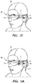
- FIGS. 17A-17G illustrate various configurations of transmission coils in electromagnetic tracking systems according to some embodiments.
- FIGS. 18A-18C illustrate signal interference effects from various system inputs according to some embodiments.
- FIG. 19 illustrate a calibration configuration according to some embodiments.
- FIGS. 20A-20C illustrate various summing amplifier configurations as between multiple subsystems.
- FIG. 21 illustrates signal overlap of multiple inputs with various signal frequencies.
- FIGS. 22A-22C illustrate various arrays of electromagnetic sensing modules according to some embodiments.
- FIGS. 23A-23C illustrate recalibration of sensors with a given known input according to some embodiments.
- FIGS. 24A-24D illustrate determining a variable in a calibration protocol according to some embodiments.
- FIGS. 25A-25B illustrate potential false readings given certain sensor inputs.
- FIG. 26 illustrates feature matching as between two images according to some embodiments.
- FIGS. 27A-27B depict methods of determining pose given sensor input according to some embodiments.
- FIGS. 28A-28G illustrates various sensor fusion corrections according to some embodiments.
- FIG. 29 illustrates a single pathway multiple layer convolutional computing architecture according to some embodiments.
- FIGS. 30A-30E illustrate various coil configurations for an electromagnetic tracking system according to some embodiments.
- FIGS. 31A-32C illustrate various thermal management configurations according to some embodiments.
- FIGS. 33-34D illustrate placement of virtual content for interaction by a user according to some embodiments.
- FIG. 35 illustrates driving assistance by placement of virtual content according to some embodiments.
- FIG. 36 illustrates virtual highlighting of content within a field of view with select information presented as a virtual display element according to some embodiments.
- FIG. 37 illustrates virtual location assistance pertinent to identify within settings that are difficult to visualize according to some embodiments.
- FIGS. 38A-38D illustrates various internal settings with placement of virtual content according to some embodiments.
- FIG. 39 illustrates various external sensors of a visual display system according to some embodiments.
- FIGS. 40A-40C illustrate teleconferencing interfaces according to some embodiments.
- FIGS. 41A-45D illustrate delivery of an “emojibomb” of various visual icons according to some embodiments.
- FIGS. 46A-46D illustrate depiction of visual themes applied to a third person according to some embodiments.
- FIGS. 47-48B illustrates translations of external inputs into readable formats according to some embodiments.
- FIG. 49 illustrates two users observing virtual content according to some embodiments.
- FIGS. 50A-50G illustrate various entertainment uses of a visual display system according to some embodiments.
- FIGS. 51A-51J illustrate various gaming environments through the aid of a visual display system according to some embodiments.
- FIGS. 52A-52I illustrate a two dimensional or three dimensional gaming instantiation according to some embodiments.
- FIGS. 53A-53C illustrate various interaction modes according to some embodiments.
- FIG. 54 illustrates an interaction content according to some embodiments.
- FIGS. 55A-55F illustrate various image presentation arrangements according to some embodiments.
- FIGS. 56A-56E illustrate various planar oriented three dimensional content interaction according to some embodiments.
- FIGS. 57A-57F illustrate various aspects of augmented reality document examination according to some embodiments.
- FIGS. 58A-58C illustrate various gaming scenarios featuring three dimensional virtual presentation according to some embodiments.
- FIGS. 59A-59C illustrate various viewing scenarios according to some embodiments.
- FIGS. 60A-60C illustrate various sporting activity enhancements according to some embodiments.
- FIGS. 61A-61F illustrate various interactions of artistic elements according to some embodiments.
- FIGS. 62A-62G illustrate various interactions in a work setting according to some embodiments.
- FIGS. 63A-63D illustrate customizable interfaces according to some embodiments.
- FIG. 64 illustrates a collaborative augmented reality session according to some embodiments.
- FIGS. 65A-65J illustrate enhanced visualizations for a workplace according to some embodiments.
- FIGS. 66A-66B illustrate augmented reality security interactions according to some embodiments.
- FIGS. 67A-67N illustrate various purchasing environments through augmented reality according to some embodiments.
- FIGS. 68A-68B illustrate augmented reality in a restaurant environment according to some embodiments.
- FIGS. 69A-69B illustrate an auxiliary wrist band coupled to an augmented reality system to display certain information according to some embodiments.
- FIG. 70 illustrates exercise conditions depicted as augmented reality to a physical setting according to some embodiments.
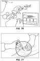
- FIGS. 71-77 illustrate various medical settings enhanced by augmented reality according to some embodiments.
- FIG. 78 illustrates an augmented reality home control setting interface according to some embodiments.
- FIG. 79 illustrates virtual representation of output of an audio device according to some embodiments.
- FIGS. 80A-80K illustrate various augmented reality presentations to a user through variations of the subject system to visualize and utilize various types of information through the portable computing capability of the subject system according to some embodiments.
- FIGS. 81A-81B illustrate enhancement of physical objects by augmented reality according to some embodiments.
- FIG. 82A-82B illustrate financial metrics interaction by augmented reality according to some embodiments.
- FIG. 83A-83H illustrate various teaching environments by augmented reality according to some embodiments.
- FIGS. 84A-84B illustrate geometric alignment of virtual content according to some embodiments.
- FIGS. 85A-85C illustrate display of remote live conditions according to some embodiments.
- FIG. 86 illustrates an augmented reality gaming scenario according to some embodiments.
- FIG. 87 illustrates a collaborative augmented reality scenario with an avatar according to some embodiments.
- FIG. 88 illustrates an augmented reality avatar presentation protocol according to some embodiments.
- FIGS. 2A-2D some general componentry options are illustrated.
- various systems, subsystems, and components are presented for addressing the objectives of providing a high-quality, comfortably-perceived display system for human VR and/or AR.
- an AR system user ( 60 ) is depicted wearing head mounted component ( 58 ) featuring a frame ( 64 ) structure coupled to a display system ( 62 ) positioned in front of the eyes of the user.
- a speaker ( 66 ) is coupled to the frame ( 64 ) in the depicted configuration and positioned adjacent the ear canal of the user (in one embodiment, another speaker, not shown, is positioned adjacent the other ear canal of the user to provide for stereo/shapeable sound control).
- the display ( 62 ) is operatively coupled ( 68 ), such as by a wired lead or wireless connectivity, to a local processing and data module ( 70 ) which may be mounted in a variety of configurations, such as fixedly attached to the frame ( 64 ), fixedly attached to a helmet or hat ( 80 ) as shown in the embodiment of FIG. 2B , embedded in headphones, removably attached to the torso ( 82 ) of the user ( 60 ) in a backpack-style configuration as shown in the embodiment of FIG. 2C , or removably attached to the hip ( 84 ) of the user ( 60 ) in a belt-coupling style configuration as shown in the embodiment of FIG. 2D .
- the local processing and data module ( 70 ) may comprise a power-efficient processor or controller, as well as digital memory, such as flash memory, both of which may be utilized to assist in the processing, caching, and storage of data a) captured from sensors which may be operatively coupled to the frame ( 64 ), such as image capture devices (such as cameras), microphones, inertial measurement units, accelerometers, compasses, GPS units, radio devices, and/or gyros; and/or b) acquired and/or processed using the remote processing module ( 72 ) and/or remote data repository ( 74 ), possibly for passage to the display ( 62 ) after such processing or retrieval.
- image capture devices such as cameras
- microphones such as inertial measurement units
- accelerometers compasses
- GPS units GPS units
- radio devices radio devices
- the local processing and data module ( 70 ) may be operatively coupled ( 76 , 78 ), such as via a wired or wireless communication links, to the remote processing module ( 72 ) and remote data repository ( 74 ) such that these remote modules ( 72 , 74 ) are operatively coupled to each other and available as resources to the local processing and data module ( 70 ).
- the remote processing module ( 72 ) may comprise one or more relatively powerful processors or controllers configured to analyze and process data and/or image information.
- the remote data repository ( 74 ) may comprise a relatively large-scale digital data storage facility, which may be available through the internet or other networking configuration in a “cloud” resource configuration. In one embodiment, all data is stored and all computation is performed in the local processing and data module, allowing fully autonomous use from any remote modules.
- FIG. 3 a schematic illustrates coordination between the cloud computing assets ( 46 ) and local processing assets, which may, for example reside in head mounted componentry ( 58 ) coupled to the user's head ( 120 ) and a local processing and data module ( 70 ), coupled to the user's belt ( 308 ; therefore the component 70 may also be termed a “belt pack” 70 ), as shown in FIG. 3 .
- the cloud ( 46 ) assets such as one or more server systems ( 110 ) are operatively coupled ( 115 ), such as via wired or wireless networking (wireless being preferred for mobility, wired being preferred for certain high-bandwidth or high-data-volume transfers that may be desired), directly to ( 40 , 42 ) one or both of the local computing assets, such as processor and memory configurations, coupled to the user's head ( 120 ) and belt ( 308 ) as described above.
- These computing assets local to the user may be operatively coupled to each other as well, via wired and/or wireless connectivity configurations ( 44 ), such as the wired coupling ( 68 ) discussed below in reference to FIG. 8 .
- primary transfer between the user and the cloud ( 46 ) may be via the link between the subsystem mounted at the belt ( 308 ) and the cloud, with the head mounted ( 120 ) subsystem primarily data-tethered to the belt-based ( 308 ) subsystem using wireless connectivity, such as ultra-wideband (“UWB”) connectivity, as is currently employed, for example, in personal computing peripheral connectivity applications.
- wireless connectivity such as ultra-wideband (“UWB”) connectivity
- a map of the world may be continually updated at a storage location which may partially reside on the user's AR system and partially reside in the cloud resources.
- the map also referred to as a “passable world model” may be a large database comprising raster imagery, 3-D and 2-D points, parametric information and other information about the real world. As more and more AR users continually capture information about their real environment (e.g., through cameras, sensors, IMUs, etc.), the map becomes more and more accurate and complete.
- one person actually present in the park near the statue may take a remotely-located friend for a walk in that park, with the friend joining through virtual and augmented reality.
- the system will need to know where the street is, wherein the trees are, where the statue is—but with that information on the cloud, the joining friend can download from the cloud aspects of the scenario, and then start walking along as an augmented reality local relative to the person who is actually in the park.
- 3-D points may be captured from the environment, and the pose (i.e., vector and/or origin position information relative to the world) of the cameras that capture those images or points may be determined, so that these points or images may be “tagged”, or associated, with this pose information.
- points captured by a second camera may be utilized to determine the pose of the second camera.
- this knowledge may be utilized to extract textures, make maps, and create a virtual copy of the real world (because then there are two cameras around that are registered).
- a person-worn system can be utilized to capture both 3-D points and the 2-D images that produced the points, and these points and images may be sent out to a cloud storage and processing resource. They may also be cached locally with embedded pose information (i.e., cache the tagged images); so the cloud may have on the ready (i.e., in available cache) tagged 2-D images (i.e., tagged with a 3-D pose), along with 3-D points. If a user is observing something dynamic, he may also send additional information up to the cloud pertinent to the motion (for example, if looking at another person's face, the user can take a texture map of the face and push that up at an optimized frequency even though the surrounding world is otherwise basically static).
- One approach to achieve high precision localization may involve the use of an electromagnetic field coupled with electromagnetic sensors that are strategically placed on the user's AR head set, belt pack, and/or other ancillary devices (e.g., totems, haptic devices, gaming instruments, etc.).
- ancillary devices e.g., totems, haptic devices, gaming instruments, etc.
- Electromagnetic tracking systems typically comprise at least an electromagnetic field emitter and at least one electromagnetic field sensor.
- the sensors may measure electromagnetic fields with a known distribution. Based on these measurements a position and orientation of a field sensor relative to the emitter is determined.
- the electromagnetic tracking system comprises an electromagnetic field emitter 402 which is configured to emit a known magnetic field.
- the electromagnetic field emitter may be coupled to a power supply 410 (e.g., electric current, batteries, etc.) to provide power to the emitter 402 .
- the electromagnetic field emitter 402 comprises several coils (e.g., at least three coils positioned perpendicular to each other to produce field in the x, y and z directions) that generate magnetic fields.
- This magnetic field is used to establish a coordinate space. This allows the system to map a position of the sensors in relation to the known magnetic field, and helps determine a position and/or orientation of the sensors.
- the electromagnetic sensors 404 a , 404 b , etc. may be attached to one or more real objects.
- the electromagnetic sensors 404 may comprise smaller coils in which current may be induced through the emitted electromagnetic field.
- the “sensor” components ( 404 ) may comprise small coils or loops, such as a set of three differently-oriented (i.e., such as orthogonally oriented relative to each other) coils coupled together within a small structure such as a cube or other container, that are positioned/oriented to capture incoming magnetic flux from the magnetic field emitted by the emitter ( 402 ), and by comparing currents induced through these coils, and knowing the relative positioning and orientation of the coils relative to each other, relative position and orientation of a sensor relative to the emitter may be calculated.
- One or more parameters pertaining to a behavior of the coils and inertial measurement unit (“IMU”) components operatively coupled to the electromagnetic tracking sensors may be measured to detect a position and/or orientation of the sensor (and the object to which it is attached to) relative to a coordinate system to which the electromagnetic field emitter is coupled.
- multiple sensors may be used in relation to the electromagnetic emitter to detect a position and orientation of each of the sensors within the coordinate space.
- the electromagnetic tracking system may provide positions in three directions (i.e., X, Y and Z directions), and further in two or three orientation angles.
- measurements of the IMU may be compared to the measurements of the coil to determine a position and orientation of the sensors.
- both electromagnetic (EM) data and IMU data may be combined to determine the position and orientation.
- This information may be transmitted (e.g., wireless communication, Bluetooth, etc.) to the controller 406 .
- pose or position and orientation
- an electromagnetic emitter is coupled to a relatively stable and large object, such as a table, operating table, wall, or ceiling, and one or more sensors are coupled to smaller objects, such as medical devices, handheld gaming components, or the like.
- a relatively stable and large object such as a table, operating table, wall, or ceiling
- one or more sensors are coupled to smaller objects, such as medical devices, handheld gaming components, or the like.
- various features of the electromagnetic tracking system may be employed to produce a configuration wherein changes or deltas in position and/or orientation between two objects that move in space relative to a more stable global coordinate system may be tracked; in other words, a configuration is shown in FIG.
- a variation of an electromagnetic tracking system may be utilized to track position and orientation delta between a head-mounted component and a hand-held component, while head pose relative to the global coordinate system (say of the room environment local to the user) is determined otherwise, such as by simultaneous localization and mapping (“SLAM”) techniques using outward-capturing cameras which may be coupled to the head mounted component of the system.
- SLAM simultaneous localization and mapping
- the controller 406 may control the electromagnetic field generator 402 , and may also capture data from the various electromagnetic sensors 404 . It should be appreciated that the various components of the system may be coupled to each other through any electro-mechanical or wireless/Bluetooth means.
- the controller 406 may also comprise data regarding the known magnetic field, and the coordinate space in relation to the magnetic field. This information is then used to detect the position and orientation of the sensors in relation to the coordinate space corresponding to the known electromagnetic field.
- electromagnetic tracking systems produce highly accurate tracking results with minimal latency and high resolution. Additionally, the electromagnetic tracking system does not necessarily rely on optical trackers, and sensors/objects not in the user's line-of-vision may be easily tracked.
- the strength of the electromagnetic field v drops as a cubic function of distance r from a coil transmitter (e.g., electromagnetic field emitter 402 ).
- an algorithm may be required based on a distance away from the electromagnetic field emitter.
- the controller 406 may be configured with such algorithms to determine a position and orientation of the sensor/object at varying distances away from the electromagnetic field emitter.
- the electromagnetic field emitter is powered by electric current (e.g., plug-in power supply) and has sensors located within 20 ft radius away from the electromagnetic field emitter. A shorter radius between the sensors and field emitter may be more desirable in many applications, including AR applications.
- the magnetic field emitter may generate magnetic fields each coil may generate an electric field in one direction (e.g., x, y or z).
- the magnetic fields may be generated with an arbitrary waveform.
- each of the axes may oscillate at a slightly different frequency.
- a coordinate space corresponding to the electromagnetic field may be determined.
- the control 406 of FIG. 4 may automatically determine a coordinate space around the emitter based on the electromagnetic field.
- a behavior of the coils at the sensors may be detected. For example, a current induced at the coils may be calculated. In other embodiments, a rotation of coils, or any other quantifiable behavior may be tracked and measured.
- this behavior may be used to detect a position and orientation of the sensor(s) and/or known object.
- the controller 406 may consult a mapping table that correlates a behavior of the coils at the sensors to various positions or orientations. Based on these calculations, the position in the coordinate space along with the orientation of the sensors may be determined.
- one or more components of the electromagnetic tracking system may need to be modified to facilitate accurate tracking of mobile components.
- tracking the user's head pose and orientation is crucial in many AR applications.
- Accurate determination of the user's head pose and orientation allows the AR system to display the right virtual content to the user.
- the virtual scene may comprise a monster hiding behind a real building.
- the view of the virtual monster may need to be modified such that a realistic AR experience is provided.
- a position and/or orientation of a totem, haptic device or some other means of interacting with a virtual content may be important in enabling the AR user to interact with the AR system.
- the AR system must detect a position and orientation of a real object in relation to virtual content. Or, when displaying a virtual interface, a position of a totem, user's hand, haptic device or any other real object configured for interaction with the AR system must be known in relation to the displayed virtual interface in order for the system to understand a command, etc.
- Conventional localization methods including optical tracking and other methods are typically plagued with high latency and low resolution problems, which makes rendering virtual content challenging in many augmented reality applications.
- the electromagnetic tracking system discussed in relation to FIGS. 4 and 5 may be adapted to the AR system to detect position and orientation of one or more objects in relation to an emitted electromagnetic field.
- Typical electromagnetic systems tend to have a large and bulky electromagnetic emitters (e.g., 402 in FIG. 4 ), which is problematic for AR devices.
- smaller electromagnetic emitters e.g., in the millimeter range
- an electromagnetic tracking system may be incorporated with an AR system as shown, with an electromagnetic field emitter 602 incorporated as part of a hand-held controller 606 .
- the hand-held controller may be a totem to be used in a gaming scenario.
- the hand-held controller may be a haptic device.
- the electromagnetic field emitter may simply be incorporated as part of the belt pack 70 .
- the hand-held controller 606 may comprise a battery 610 or other power supply that powers that electromagnetic field emitter 602 .
- the electromagnetic field emitter 602 may also comprise or be coupled to an IMU 650 component configured to assist in determining positioning and/or orientation of the electromagnetic field emitter 602 relative to other components. This may be especially important in cases where both the field emitter 602 and the sensors ( 604 ) are mobile. Placing the electromagnetic field emitter 602 in the hand-held controller rather than the belt pack, as shown in the embodiment of FIG. 6 , ensures that the electromagnetic field emitter is not competing for resources at the belt pack, but rather uses its own battery source at the hand-held controller 606 .
- the electromagnetic sensors 604 may be placed on one or more locations on the user's headset, along with other sensing devices such as one or more IMUs or additional magnetic flux capturing coils 608 .
- sensors ( 604 , 608 ) may be placed on either side of the head set ( 58 ). Since these sensors are engineered to be rather small (and hence may be less sensitive, in some cases), having multiple sensors may improve efficiency and precision.
- one or more sensors may also be placed on the belt pack 70 or any other part of the user's body.
- the sensors 604 , 608 ) may communicate wirelessly or through Bluetooth to a computing apparatus that determines a pose and orientation of the sensors (and the AR headset to which it is attached).
- the computing apparatus may reside at the belt pack 70 .
- the computing apparatus may reside at the headset itself, or even the hand-held controller 606 .
- the computing apparatus may in turn comprise a mapping database (e.g., passable world model, coordinate space, etc.) to detect pose, to determine the coordinates of real objects and virtual objects, and may even connect to cloud resources and the passable world model, in one or more embodiments.
- a mapping database e.g., passable world model, coordinate space, etc.
- the electromagnetic field emitter may be engineered to be compact, using smaller coils compared to traditional systems.
- a shorter radius between the electromagnetic sensors 604 and the electromagnetic field emitter 602 may reduce power consumption when compared to conventional systems such as the one detailed in FIG. 4 .
- This aspect may either be utilized to prolong the life of the battery 610 that may power the controller 606 and the electromagnetic field emitter 602 , in one or more embodiments. Or, in other embodiments, this aspect may be utilized to reduce the size of the coils generating the magnetic field at the electromagnetic field emitter 602 . However, in order to get the same strength of magnetic field, the power may be need to be increased. This allows for a compact electromagnetic field emitter unit 602 that may fit compactly at the hand-held controller 606 .
- IMU-based pose tracking may be used in the sensors.
- the IMUs must remain as stable as possible in order to increase an efficiency of the pose detection process.
- the IMUs may be engineered such that they remain stable up to 50-100 milliseconds.
- IMUs may utilize an outside pose estimator module (i.e., IMUs may drift over time) that may enable pose updates to be reported at a rate of 10-20 Hz. By keeping the IMUs stable at a reasonable rate, the rate of pose updates may be dramatically decreased to 10-20 Hz (as compared to higher frequencies in conventional systems).
- the electromagnetic tracking system can be run at a 10% duty cycle (e.g., only pinging for ground truth every 100 milliseconds), this would be another way to save power at the AR system. This would mean that the electromagnetic tracking system wakes up every 10 milliseconds out of every 100 milliseconds to generate a pose estimate. This directly translates to power consumption savings, which may, in turn, affect size, battery life and cost of the AR device.
- this reduction in duty cycle may be strategically utilized by providing two hand-held controllers (not shown) rather than just one.
- the user may be playing a game that requires two totems, etc.
- two users may have their own totems/hand-held controllers to play the game.
- the controllers may operate at offset duty cycles.
- the same concept may also be applied to controllers utilized by two different users playing a multi-player game, for example.
- the hand-held controller emits a magnetic field.
- the electromagnetic sensors (placed on headset, belt pack, etc.) detect the magnetic field.
- a position and orientation of the headset/belt is determined based on a behavior of the coils/IMUs at the sensors.
- the pose information is conveyed to the computing apparatus (e.g., at the belt pack or headset).
- a mapping database e.g., passable world model
- virtual content may be delivered to the user at the AR headset.
- an electromagnetic tracking system similar to the one outlined in FIG. 6 enables pose tracking (e.g., head position and orientation, position and orientation of totems, and other controllers). This allows the AR system to project virtual content with a higher degree of accuracy, and very low latency when compared to optical tracking techniques.
- pose tracking e.g., head position and orientation, position and orientation of totems, and other controllers.
- a head mounted wearable component ( 58 ) is shown operatively coupled ( 68 ) to a local processing and data module ( 70 ), such as a belt pack, here using a physical multicore lead which also features a control and quick release module ( 86 ) as described below in reference to FIGS. 9A-9F .
- the local processing and data module ( 70 ) is operatively coupled ( 100 ) to a hand held component ( 606 ), here by a wireless connection such as low power Bluetooth; the hand held component ( 606 ) may also be operatively coupled ( 94 ) directly to the head mounted wearable component ( 58 ), such as by a wireless connection such as low power Bluetooth.
- a high-frequency connection is desirable, such as in the range of hundreds or thousands of cycles/second or higher; tens of cycles per second may be adequate for electromagnetic localization sensing, such as by the sensor ( 604 ) and transmitter ( 602 ) pairings.
- a global coordinate system ( 10 ) representative of fixed objects in the real world around the user, such as a wall ( 8 ).
- Cloud resources ( 46 ) also may be operatively coupled ( 42 , 40 , 88 , 90 ) to the local processing and data module ( 70 ), to the head mounted wearable component ( 58 ), to resources which may be coupled to the wall ( 8 ) or other item fixed relative to the global coordinate system ( 10 ), respectively.
- the resources coupled to the wall ( 8 ) or having known positions and/or orientations relative to the global coordinate system ( 10 ) may include a WiFi transceiver ( 114 ), an electromagnetic emitter ( 602 ) and/or receiver ( 604 ), a beacon or reflector ( 112 ) configured to emit or reflect a given type of radiation, such as an infrared LED beacon, a cellular network transceiver ( 110 ), a RADAR emitter or detector ( 108 ), a LIDAR emitter or detector ( 106 ), a GPS transceiver ( 118 ), a poster or marker having a known detectable pattern ( 122 ), and a camera ( 124 ).
- a WiFi transceiver 114
- an electromagnetic emitter 602
- receiver 604
- a beacon or reflector 112
- a given type of radiation such as an infrared LED beacon
- a RADAR emitter or detector 108
- the head mounted wearable component ( 58 ) features similar components, as illustrated, in addition to lighting emitters ( 130 ) configured to assist the camera ( 124 ) detectors, such as infrared emitters ( 130 ) for an infrared camera ( 124 ); also featured on the head mounted wearable component ( 58 ) are one or more strain gauges ( 116 ), which may be fixedly coupled to the frame or mechanical platform of the head mounted wearable component ( 58 ) and configured to determine deflection of such platform in between components such as electromagnetic receiver sensors ( 604 ) or display elements ( 62 ), wherein it may be valuable to understand if bending of the platform has occurred, such as at a thinned portion of the platform, such as the portion above the nose on the eyeglasses-like platform depicted in FIG.
- the head mounted wearable component ( 58 ) also features a processor ( 128 ) and one or more IMUs ( 102 ). Each of the components preferably are operatively coupled to the processor ( 128 ).
- the hand held component ( 606 ) and local processing and data module ( 70 ) are illustrated featuring similar components. As shown in FIG. 8 , with so many sensing and connectivity means, such a system is likely to be heavy, power hungry, large, and relatively expensive. However, for illustrative purposes, such a system may be utilized to provide a very high level of connectivity, system component integration, and position/orientation tracking.
- the various main mobile components ( 58 , 70 , 606 ) may be localized in terms of position relative to the global coordinate system using WiFi, GPS, or Cellular signal triangulation; beacons, electromagnetic tracking (as described above), RADAR, and LIDIR systems may provide yet further location and/or orientation information and feedback. Markers and cameras also may be utilized to provide further information regarding relative and absolute position and orientation.
- the various camera components ( 124 ) such as those shown coupled to the head mounted wearable component ( 58 ), may be utilized to capture data which may be utilized in simultaneous localization and mapping protocols, or “SLAM”, to determine where the component ( 58 ) is and how it is oriented relative to other components.
- SLAM simultaneous localization and mapping protocols
- FIGS. 9A-9F various aspects of the control and quick release module ( 86 ) are depicted.
- FIG. 9A two outer housing components are coupled together using a magnetic coupling configuration which may be enhanced with mechanical latching. Buttons ( 136 ) for operation of the associated system may be included.
- FIG. 9B illustrates a partial cutaway view with the buttons ( 136 ) and underlying top printed circuit board ( 138 ) shown.
- FIG. 9C with the buttons ( 136 ) and underlying top printed circuit board ( 138 ) removed, a female contact pin array ( 140 ) is visible.
- FIG. 9A two outer housing components are coupled together using a magnetic coupling configuration which may be enhanced with mechanical latching. Buttons ( 136 ) for operation of the associated system may be included.
- FIG. 9B illustrates a partial cutaway view with the buttons ( 136 ) and underlying top printed circuit board ( 138 ) shown.
- FIG. 9C with the buttons ( 136 ) and underlying top printed circuit board (
- the lower printed circuit board ( 142 ) is visible. With the lower printed circuit board ( 142 ) removed, as shown in FIG. 9E , a male contact pin array ( 144 ) is visible.
- the pins may be termed “pogo pins” and generally comprise a highly conductive material, such as copper or gold.
- the illustrated configuration mates 46 male pins with female pins, and the entire assembly may be quick-release decoupled in half by manually pulling it apart and overcoming a magnetic interface ( 146 ) load which may be developed using north and south magnets oriented around the perimeters of the pin arrays ( 140 , 144 ).
- a magnetic interface ( 146 ) load which may be developed using north and south magnets oriented around the perimeters of the pin arrays ( 140 , 144 ).
- an approximate 2 kg load from compressing the 46 pogo pins is countered with a closure maintainance force of about 4 kg.
- the pins in the array may be separated by about 1.3 mm, and the pins may be operatively coupled to conductive lines of various types, such as twisted pairs or other combinations to support USB 3.0, HDMI 2.0, I2S signals, GPIO, and MIPI configurations, and high current analog lines and grounds configured for up to about 4 amps/5 volts in one embodiment.
- FIG. 11A an electromagnetic sensing coil assembly ( 604 , i.e., 3 individual coils coupled to a housing) is shown coupled to a head mounted component ( 58 ); such a configuration adds additional geometry to the overall assembly which may not be desirable.
- FIG. 11B rather than housing the coils in a box or single housing as in the configuration of FIG. 11A , the individual coils may be integrated into the various structures of the head mounted component ( 58 ), as shown in FIG. 11B .
- FIGS. 12A-12E illustrate various configurations for featuring a ferrite core coupled to an electromagnetic sensor to increase field sensitivity; the embodiments of FIGS. 12B-12E are lighter in weight than the solid core configuration of FIG. 12A and may be utilized to save mass.
- time division multiplexing may be utilized to save mass as well.
- TDM time division multiplexing
- FIG. 13A a conventional local data processing configuration is shown for a 3-coil electromagnetic receiver sensor, wherein analog currents come in from each of the X, Y, and Z coils, go into a pre-amplifier, go into a band pass filter, through analog-to-digital conversion, and ultimately to a digital signal processor.
- time division multiplexing may be utilized to share hardware, such that each coil sensor chain doesn't require its own amplifiers, etc.
- signal to noise ratios may be increased by having more than one set of electromagnetic sensors, each set being relatively small relative to a single larger coil set; also the low-side frequency limits, which generally are needed to have multiple sensing coils in close proximity, may be improved to facilitate bandwidth requirement improvements. Also, there is a tradeoff with multiplexing, in that multiplexing generally spreads out the reception of radiofrequency signals in time, which results in generally dirtier signals; thus larger coil diameter may be required for multiplexed systems.
- a multiplexed system may require a 9 mm-side dimension cubic coil sensor box
- a nonmultiplexed system may only require a 7 mm-side dimension cubic coil box for similar performance; thus there are tradeoffs in minimizing geometry and mass.
- the system may be configured to selectively utilize the sensor and emitter pairing that are closest to each other to optimize the performance of the system.
- a head mounted component assembly may capture a combination of IMU and camera data (the camera data being used, for example, for SLAM analysis, such as at the belt pack processor where there may be more raw processing horsepower present) to determine and update head pose (i.e., position and orientation) relative to a real world global coordinate system ( 162 ).
- the user may also activate a handheld component to, for example, play an augmented reality game ( 164 ), and the handheld component may comprise an electromagnetic transmitter operatively coupled to one or both of the belt pack and head mounted component ( 166 ).
- One or more electromagnetic field coil receiver sets (i.e., a set being 3 differently-oriented individual coils) coupled to the head mounted component to capture magnetic flux from the transmitter, which may be utilized to determine positional or orientational difference (or “delta”), between the head mounted component and handheld component ( 168 ).
- the combination of the head mounted component assisting in determining pose relative to the global coordinate system, and the hand held assisting in determining relative location and orientation of the handheld relative to the head mounted component allows the system to generally determine where each component is relative to the global coordinate system, and thus the user's head pose, and handheld pose may be tracked, preferably at relatively low latency, for presentation of augmented reality image features and interaction using movements and rotations of the handheld component ( 170 ).
- FIG. 15 an embodiment is illustrated that is somewhat similar to that of FIG. 14 , with the exception that the system has many more sensing devices and configurations available to assist in determining pose of both the head mounted component ( 172 ) and a hand held component ( 176 , 178 ), such that the user's head pose, and handheld pose may be tracked, preferably at relatively low latency, for presentation of augmented reality image features and interaction using movements and rotations of the handheld component ( 180 ).
- FIGS. 16A and 16B various aspects of a configuration similar to that of FIG. 8 are shown.
- the configuration of FIG. 16A differs from that of FIG. 8 in that in addition to a LIDAR ( 106 ) type of depth sensor, the configuration of FIG. 16A features a generic depth camera or depth sensor ( 154 ) for illustrative purposes, which may, for example, be either a stereo triangulation style depth sensor (such as a passive stereo depth sensor, a texture projection stereo depth sensor, or a structured light stereo depth sensor) or a time or flight style depth sensor (such as a LIDAR depth sensor or a modulated emission depth sensor); further, the configuration of FIG.
- a stereo triangulation style depth sensor such as a passive stereo depth sensor, a texture projection stereo depth sensor, or a structured light stereo depth sensor
- a time or flight style depth sensor such as a LIDAR depth sensor or a modulated emission depth sensor
- FIG. 16A has an additional forward facing “world” camera ( 124 , which may be a grayscale camera, having a sensor capable of 720 p range resolution) as well as a relatively high-resolution “picture camera” ( 156 , which may be a full color camera, having a sensor capable of 2 megapixel or higher resolution, for example).
- FIG. 16B shows a partial orthogonal view of the configuration of FIG. 16A for illustrative purposes, as described further below in reference to FIG. 16B .
- each of these depth sensor types may be employed with a wearable computing solution as disclosed herein, although each has various advantages and disadvantages.
- many depth sensors have challenges with black surfaces and shiny or reflective surfaces.
- Passive stereo depth sensing is a relatively simplistic way of getting triangulation for calculating depth with a depth camera or sensor, but it may be challenged if a wide field of view (“FOV”) is required, and may require relatively significant computing resource; further, such a sensor type may have challenges with edge detection, which may be important for the particular use case at hand.
- Passive stereo may have challenges with textureless walls, low light situations, and repeated patterns.
- Passive stereo depth sensors are available from manufacturers such as Intel® and Aquifi®.
- Stereo with texture projection also known as “active stereo”
- a texture projector broadcasts a projection pattern onto the environment, and the more texture that is broadcasted, the more accuracy is available in triangulating for depth calculation.
- Active stereo may also require relatively high compute resource, present challenges when wide FOV is required, and be somewhat suboptimal in detecting edges, but it does address some of the challenges of passive stereo in that it is effective with textureless walls, is good in low light, and generally does not have problems with repeating patterns.
- Active stereo depth sensors are available from manufacturers such as Intel® and Aquifi®.
- Stereo with structured light such as the systems developed by Primesense, Inc.® and available under the tradename Kinect®, as well as the systems available from Mantis Vision, Inc®, generally utilize a single camera/projector pairing, and the projector is specialized in that it is configured to broadcast a pattern of dots that is known apriori. In essence, the system knows the pattern that is broadcasted, and it knows that the variable to be determined is depth.
- Such configurations may be relatively efficient on compute load, and may be challenged in wide FOV requirement scenarios as well as scenarios with ambient light and patterns broadcasted from other nearby devices, but can be quite effective and efficient in many scenarios.
- an emitter may be configured to send out a wave, such as a sine wave, of amplitude modulated light; a camera component, which may be positioned nearby or even overlapping in some configurations, receives a returning signal on each of the pixels of the camera component and depth mapping may be determined/calculated.
- a wave such as a sine wave
- a camera component which may be positioned nearby or even overlapping in some configurations, receives a returning signal on each of the pixels of the camera component and depth mapping may be determined/calculated.
- Such configurations may be relatively compact in geometry, high in accuracy, and low in compute load, but may be challenged in terms of image resolution (such as at edges of objects), multi-path errors (such as wherein the sensor is aimed at a reflective or shiny corner and the detector ends up receiving more than one return path, such that there is some depth detection aliasing.
- Direct time of flight sensors which also may be referred to as the aforementioned LIDAR, are available from suppliers such as LuminAR® and Advanced Scientific Concepts, Inc.®. With these time of flight configurations, generally a pulse of light (such as a picosecond, nanosecond, or femtosecond long pulse of light) is sent out to bathe the world oriented around it with this light ping; then each pixel on a camera sensor waits for that pulse to return, and knowing the speed of light, the distance at each pixel may be calculated.
- Such configurations may have many of the advantages of modulated time of flight sensor configurations (no baseline, relatively wide FOV, high accuracy, relatively low compute load, etc) and also relatively high framerates, such as into the tens of thousands of Hertz. They may also be relatively expensive, have relatively low resolution, be sensitive to bright light, and susceptible to multi-path errors; they may also be relatively large and heavy.
- FIG. 16B a partial top view is shown for illustrative purposes featuring a user's eyes ( 12 ) as well as cameras ( 14 , such as infrared cameras) with fields of view ( 28 , 30 ) and light or radiation sources ( 16 , such as infrared) directed toward the eyes ( 12 ) to facilitate eye tracking, observation, and/or image capture.
- the three outward-facing world-capturing cameras ( 124 ) are shown with their FOVs ( 18 , 20 , 22 ), as is the depth camera ( 154 ) and its FOV ( 24 ), and the picture camera ( 156 ) and its FOV ( 26 ).
- the depth information garnered from the depth camera ( 154 ) may be bolstered by using the overlapping FOVs and data from the other forward-facing cameras.
- the system may end up with something like a sub-VGA image from the depth sensor ( 154 ), a 720p image from the world cameras ( 124 ), and occasionally a 2 megapixel color image from the picture camera ( 156 ).
- Such a configuration has 4 cameras sharing common FOV, two of them with heterogeneous visible spectrum images, one with color, and the third one with relatively low-resolution depth.
- the system may be configured to do a segmentation in the grayscale and color images, fuse those two and make a relatively high-resolution image from them, get some stereo correspondences, use the depth sensor to provide hypotheses about stereo depth, and use stereo correspondences to get a more refined depth map, which may be significantly better than what was available from the depth sensor only.
- Such processes may be run on local mobile processing hardware, or can run using cloud computing resources, perhaps along with the data from others in the area (such as two people sitting across a table from each other nearby), and end up with quite a refined mapping.
- all of the above sensors may be combined into one integrated sensor to accomplish such functionality.
- FIGS. 17A-17G aspects of a dynamic transmission coil tuning configuration are shown for electromagnetic tracking, to facilitate the transmission coil to operate optimally at multiple frequencies per orthogonal axis, which allows for multiple users to operate on the same system.
- an electromagnetic tracking transmitter will be designed to operate at fixed frequencies per orthogonal axis.
- each transmission coil is tuned with a static series capacitance that creates resonance only at the frequency of operation. Such resonance allows for the maximum possible current flow through the coil which, in turn, maximizes the magnetic flux generated.
- FIG. 17A illustrates a typical resonant circuit used to create resonance.
- Element “L 1 ” represents a single axis transmission coil at 1 mH, and with capacitance set to 52 nF, resonance is created at 22 kHz, as shown in FIG. 17B .
- FIG. 17C shows the current through the system plotted versus frequency, and it may be seen that the current is maximum at the resonant frequency. If this system is expected to operate any other frequency, the operating circuit will not be at the possible maximum.
- FIG. 17D illustrates an embodiment of a dynamically tunable configuration. The dynamic frequency tuning may be set to achieve resonance on the coil to get maximum current flow; an example of a tunable circuit is shown in FIG. 17E , where one capacitor (“C 4 ”) may be tuned to produce simulated data, as shown in FIG. 17F . As shown in FIG. 17F , one of the orthogonal coils of an electromagnetic tracker is simulated as “L 1 ” and a static capacitor (“C 5 ”) is a fixed high voltage capacitor.
- FIG. 17F illustrates the resonance achieved with the higher plots ( 248 ) versus the lower plots ( 250 ); as C 4 is varied in the simulation, the resonance is changed, and it is notable that the voltage across C 5 (Vmid-Vout) is higher than that across C 4 (Vout). This generally will allow for a smaller package part on C 4 since multiples of this generally will be needed for the system, one per frequency of operation.
- FIG. 17G illustrates that the maximum current achieved follows the resonance regardless of voltage across capacitors.
- an electromagnetic tracking system may be bounded to work below about 30 KHz, which is slightly higher than the audible range for human hearing.
- FIG. 18A there may be some audio systems which create noise in the usable frequencies for such electromagnetic tracking systems.
- audio speakers typically have magnetic fields and one or more coils which also may interfere with electromagnetic tracking systems.
- FIG. 18B a block diagram is shown for a noise cancelling configuration for elecromagnetic tracking interference. Since the unintentional interference is a known entity, this knowledge can be used to cancel the interference and improve performance. In other words, the audio generated by the system may be utilized to eliminate the effects received by the receiver coil.
- the noise cancelling circuit may be configured to accept the corrupted signals from the EM amplifier as well as the signal from the audio system, and the noise cancelling system will cancel out the noise received from the audio speaker.
- FIG. 18C illustrates a plot to show an example of the how the signal can be inverted and added to cancel the interferer. V(vnoise), the top plot, is the noise added to the system by the audio speaker. Referring to FIG.
- a known pattern (such as a circular pattern) of lights or other emitters may be utilized to assist in calibration of vision systems.
- the circular pattern may be utilized as a fiducial; as a camera or other capture device with known orientation captures the shape of the pattern while the object coupled to the pattern is reoriented, the orientation of the object, such as a hand held totem device, may be determined; such orientation may be compared with that which comes from an associated IMU device for error determination and use in calibration.
- FIGS. 20A-20C a configuration is shown with a summing amplifier to simplify circuitry between two subsystems or components of a wearable computing configuration such as a head mounted component and belt-pack component.
- a summing amplifier to simplify circuitry between two subsystems or components of a wearable computing configuration such as a head mounted component and belt-pack component.
- each of the coils (on the left of FIG. 20A ) of an electromagnetic tracking sensor is associated with an amplifier, and three distinct amplified signals would be sent through the cabling to the other component.
- the three three distinct amplified signals may be directed to a summing amplifier, which produces one amplified signal that is directed down an advantageously simplified cable, each signal at a different frequency.
- the summing amplifier may be configured to amplify all three signals coming in; then the receiving digital signal processor, after analog-to-digital conversion, separates the signals at the other end.
- FIG. 20C illustrates a filter for each frequency—so the signals may be separated back out at such stage.
- electromagnetic (“EM”) tracking updating is relatively “expensive” in terms of power for a portable system, and may not be capable of very high frequency updating.
- EM electromagnetic
- sensor fusion more frequently updated localization information or other dynamic inputs (measurable metrics that change over time) from another sensor such as an IMU may be combined, along with data from another sensor, such as an optical sensor (such as a camera or depth camera), which may or may not be at a relatively high frequency; the net of fusing all of these inputs places a lower demand upon the EM system and provides for quicker updating.
- dynamic inputs include temperature fluctuations, audio volume, sizing such as dimensions of or distance to certain objects, and not merely position or orientation of a user.
- a set of dynamic inputs represents a collection of those inputs as a function of a given variable (such as time).
- a distributed sensor coil configuration was shown.
- a configuration with a single electromagnetic sensor device ( 604 ), such as a box containing three orthogonal coils, one for each direction of X, Y, Z, may be coupled to the wearable component ( 58 ) for 6 degree of freedom tracking, as described above.
- a device may be dis-integrated, with the three sub-portions (i.e., coils) attached at different locations of the wearable component ( 58 ), as shown in FIG. 22B .
- each individual coil may be replaced with a group of similarly oriented coils, such that the overall magnetic flux for any given orthogonal direction is captured by the group ( 148 , 150 , 152 ) rather than by a single coil for each orthogonal direction.
- a group of smaller coils may be utilized and their signals aggregated to form the signal for that orthogonal direction.
- FIGS. 23A-23C it may be useful to recalibrate a wearable computing system such as those discussed herein from time to time, and in one embodiment, ultrasonic signals at the transmitter, along with a microphone at the receiver and acoustic time of flight calculation, may be utilized to determine sound propagation delay.
- FIG. 23A shows that in one embodiment, 3 coils on the transmitter are energized with a burst of sinewaves, and at the same time an ultrasonic transducer may be energized with a burst of sinewave, preferably of the same frequency as one of the coils.
- FIG. 23B illustrates that a receiver may be configured to receive the 3 EM waves using sensor coils, and the ultrasonic wave using a microphone device.
- Total distance may be calculated from the amplitude of the 3 EM signals; then time of flight may be calculated by comparing the timing of the microphone response with that of the EM coils ( FIG. 23C ). This may be used to calculate distance and calibrate the EM correction factors.
- the distance may be calculated by measuring the size in pixels of a known-size feature on another device such as a handheld controller.
- the distance may be calculated by such depth sensor and reported directly to the controller.
- a depth sensor such as an infrared (“IR”) depth sensor
- either the camera or the depth sensor can be used to determine position in space.
- the augmented reality system may be configured to project one or more virtual targets to the user.
- the user may align the controller to the targets, and the system calculates position from both the EM response, and from the direction of the virtual targets plus the previously calculated distance.
- Roll angle calibration may be done by aligning a known feature on the controller with a virtual target projected to the user; yaw and Pitch angle may be calibrated by presenting a virtual target to the user and having the user align two features on the controller with the target (much like sighting a rifle).
- a receiver would generate a similar response in two diagonally opposed locations around the transmitter. Such a challenge is particularly relevant in systems wherein both the transmitter and receiver may be mobile relative to each other.
- one may use an IMU sensor to see if you're on the plus or the negative side of the symmetry axis.
- info to detect whether a handheld component is in the positive side or negative side of the reference axis; if the handheld is outside of the field of view of the camera and/or depth sensor, the system may be configured to decide (or the user may decide) that it must be in the 180 zone directly in back of the user, for example.
- outward-oriented camera devices ( 124 , 154 , 156 ) are coupled to a system component such as a head mounted component ( 58 )
- the position and orientation of the head coupled to such head mounted component ( 58 ) may be determined using information gathered from these camera devices, using techniques such as simultaneous localization and mapping, or “SLAM” techniques (also known as parallel tracking and mapping, or “PTAM” techniques).
- SLAM simultaneous localization and mapping
- PTAM parallel tracking and mapping
- a typical SLAM or PTAM configuration involves extracting features from incoming image information and using this to triangulate 3-D mapping points, and then tracking against those 3-D mapping points.
- SLAM techniques have been utilized in many implementations, such as in self-driving cars, where computing, power, and sensing resources may be relatively plentiful when compared with those which might be available on board a wearable computing device, such as a head mounted component ( 58 ).
- a wearable computing device such as a head mounted component ( 58 ) may comprise two outward-facing cameras producing two camera images (left— 204 , right— 206 ).
- a relatively lightweight, portable, and power efficient embedded processor such as those sold by Movidius®, Intel®, Qualcomm®, or Ceva®, may comprise part of the head mounted component ( 58 ) and be operatively coupled to the camera devices.
- the embedded processor may be configured to first extract features ( 210 , 212 ) from the camera images ( 204 , 206 ).
- the system can triangulate ( 214 ) 3-D mapping points of those features, resulting in a set of sparse 3-D map points ( 202 ). This may be stored as the “map”, and these first frames may be utilized to establish the “world” coordinate system origin ( 208 ).
- the system may be configured to project the 3-D map points into the new image information, and compare with locations of 2-D features that have been detected in the image information.
- the system may be configured to attempt to establish a 2-D to 3-D correspondence, and using a group of such correspondences, such as about six of them, the pose of the user's head (which is, of course, coupled to the head mounted device 58 ) may be estimated.
- a greater number of correspondences such as more than six, generally means a better job of estimating the pose.
- this analysis relies upon having some sense of where the user's head was (i.e., in terms of position and orientation) before the current images being examined.
- the system may use the pose estimate from the most immediately previous time to estimate where the head is for the most current data.
- the system may be configured to estimate that the user's head is not far from that in terms of position and/or orientation, and may search around that to find correspondences for the current time interval. Such is a basis of one embodiment of a tracking configuration.
- one or both camera images ( 204 , 206 ) may start to lose the map points in the newly incoming images (for example, if the user's head is rotating right in space, the original map points may start to disappear to the left and may only appear in the left image, and then not at all with more rotation).
- the system may be configured to create new map points, such as by using a process similar to that described above (detect features, create new map points)—this is how the system may be configured to keep populating the map.
- this process may be repeated again every 10 to 20 frames, depending upon how much the user is translating and/or rotating his head relative to his environment, and thereby translating and/or rotating the associated cameras.
- Frames associated with newly created mapping points may be deemed “key frames,” and the system may be configured to delay the feature detection process with key frames, or alternatively, feature detection may be conducted upon each frame to try to establish matches, and then when the system is ready to create a new key frame, the system already has that associated feature detection completed.
- the basic paradigm is to start off creating a map, and then track, track, track until the system needs to create another map or additional portion thereof.
- vision based pose calculation may be split into 5 stages (pre-tracking 216 , tracking 218 , low-latency mapping 220 , latency-tolerant mapping 222 , post mapping/cleanup 224 ) to assist with precision and optimization for embedded processor configurations wherein computation, power, and sensing resources may be limited.
- the system may be configured to identify which map points project into the image before the image information arrives.
- the system may be configured to identify which map points would project into the image given that the system knows where the user was before, and has a sense or where the user is going.
- one of the inputs that the system may get from a sensor fusion module or functionality may be “post estimation” information, at a relatively fast rate, such as at 250 Hz from an inertial measurement unit (“IMU”) or other sensor or device (this is a high rate relative to, say, 30 Hz, at which the vision based pose calculation operation may be providing updates).
- IMU inertial measurement unit
- the data from devices such as IMUs tends to be somewhat noisy and susceptible to pose estimation drift, as discussed below.
- the IMU data may be quite useful in predicting pose, and, again, when combined with other data in a sensor fusion configuration, an optimized overall result may be determined. For example, and as explained in greater detail below with reference to FIG. 28B-28G , a propagation path of collected points may be adjusted, and from that adjustment a pose at a later time may be estimated/informed by where sensor fusion determines a future point may be based on the adjusted propagation path.
- Pose information coming from a sensor fusion module or functionality may be termed “pose prior”, and this pose prior may be utilized by the system to estimate which sets of points are going to project into the current image.
- the system is configured in a “pre tracking” step ( 216 ) to pre-fetch those map points and conduct some pre-processing that helps to reduce latency of overall processing.
- Each of the 3-D map points may be associated with a descriptor, so that the system may identify them uniquely and match them to regions in the image.
- the system may be configured to maintain some semblance of that patch along with the map point, so that when the map point is seen projected onto other images, the system can look back at the original image used to create the map, examine the patch correlation, and determine if they are the same point.
- the system may be configured to do some amount of fetching of map points, and some amount of pre-processing associated with the patches associated with those map points.
- the system may be configured to pre-fetch map points, and pre-warp image patches (a “warp” of an image may be done to ensure that the system can match the patch associated with the map point with the current image; it's a way to make sure that the data being compared is compatible).
- a tracking stage may comprise several components, such as feature detection, optical flow analysis, feature matching, and pose estimation. While detecting features in the incoming image data, the system may be configured to utilize optical flow analysis to save computational time in feature detection by trying to follow features from one or more previous images. Once features have been identified in the current image, the system may be configured to try to match the features with projected map points—this may be deemed the “feature matching” portion of the configuration.
- the system preferably has already identified which map points are of interest, and fetched them; in feature mapping, they are projected into the current image and the system tries to match them with the features.
- the output of feature mapping is the set of 2-D to 3-D correspondences, and with that in hand, the system is configured to estimate the pose.
- the system preferably is configured to identify if the user is looking at a new region of the environment or not, to determine whether a new key frame is needed. In one embodiment, such analysis of whether a new key frame is needed may be almost purely based upon geometry; for example, the system may be configured to look at the distance (translational distance; also field-of-view capture reorientation—the user's head may be close translationally but re-oriented such that completely new map points are required, for example) from the current frame to the remaining key frames.
- the mapping stage may be started.
- the system may be configured to operate mapping as three different operations (low-latency mapping, latency-tolerant mapping, post/mapping or cleanup), as opposed to a single mapping operation more likely seen in a conventional SLAM or PTAM operation.
- Low-latency mapping ( 220 ), which may be thought of in a simplistic form as triangulation and creation of new map points, is a critical stage, with the system preferably configured to conduct such stage immediately, because the paradigm of tracking discussed herein relies upon map points, with the system only finding a position if there are map points available to track against.
- the “low-latency” denomination refers to the notion that there is no tolerance for unexcused latency (in other words, this part of the mapping needs to be conducted as quickly as possible or the system has a tracking problem).
- Latency-tolerant mapping ( 222 ) may be thought of in a simplistic form as an optimization stage.
- the overall process does not absolutely require low latency to conduct this operation known as “bundle adjustment”, which provides a global optimization in the result.
- the system may be configured to examine the positions of 3-D points, as well as where they were observed from. There are many errors that can chain together in the process of creating map points.
- the bundle adjustment process may take, for example, particular points that were observed from two different view locations and use all of this information to gain a better sense of the actual 3-D geometry.
- the result may be that the 3-D points and also the calculated trajectory (i.e., location, path of the capturing cameras) may be adjusted by a small amount. It is desirable to conduct these kinds of processes to not accumulate errors through the mapping/tracking process.
- the post mapping/cleanup ( 224 ) stage is one in which the system may be configured to remove points on the map that do not provide valuable information in the mapping and tracking analysis. In this stage, these points that do not provide useful information about the scene are removed, and such analysis is helpful in keeping the entire mapping and tracking process scaleable.
- semantic segmentation and/or object detection techniques may be utilized to remove moving objects from the pertinent field, such as humans, moving vehicles, and the like, so that features for mapping and tracking are not extracted from these regions of the various images.
- deep learning techniques such as those described below, may be utilized for segmenting out these non-static objects.
- pose data is received over time, such that an estimated pose at a future time may be extrapolated at 2730 .
- Extrapolation may be simple constant value extrapolation from given inputs, or corrected extrapolation based on correction input points as described below with reference to sensor fusion.
- the system accesses a feature map for that position. For example, if a user is walking while wearing a head mounted component, the system may extrapolate a future position based on the pace of the user and access a feature map for that extrapolated/estimated position. In some embodiments, this step is pre-fetching as described above with reference to step ( 216 ) of FIG. 27A .
- this step is pre-fetching as described above with reference to step ( 216 ) of FIG. 27A .
- specific points of the feature map are extracted, and in some embodiments, patches surrounding the points are extracted as well.
- the extracted points are processed. In some embodiments, processing comprises warping the points to match an estimated orientation or find a nomography of the extracted points or patches.
- a sensor fusion configuration may be utilized to benefit from one source of information coming from a sensor with relatively high update frequency (such as an IMU updating gyro, accelerometer, and/or magnetometer data pertinent to head pose at a frequency such as 250 Hz) and another information source updating at a lower frequency (such as a vision based head pose measurement process updating at a frequency such as 30 Hz).
- a sensor with relatively high update frequency such as an IMU updating gyro, accelerometer, and/or magnetometer data pertinent to head pose at a frequency such as 250 Hz
- another information source updating at a lower frequency such as a vision based head pose measurement process updating at a frequency such as 30 Hz.
- the system may be configured to use an extended Kalman filter (“EKF”, 232 ) and to track a significant amount of information regarding the device. For example, in one embodiment, it may account for 32 states, such as angular velocity (i.e., from the IMU gyroscope), translational acceleration (i.e., from the IMU accelerometers), calibration information for the IMU itself (i.e., coordinate systems and calibration factors for the gyros and accelerometers; the IMU may also comprise one or more magnetometers).
- EKF extended Kalman filter
- the system may be configured to take in IMU measurements at a relatively high update frequency ( 226 ), such as 250 Hz, as well as data from some other source at a lower update frequency (i.e., calculated vision pose measurement, odometry data, etc), here vision pose measurement ( 228 ) at an update frequency such as 30 Hz.
- a relatively high update frequency 226
- data from some other source at a lower update frequency
- vision pose measurement 228
- an update frequency such as 30 Hz.
- the system may be configured to integrate the angular velocity information to get rotational information (i.e., the integral of angular velocity (change in rotational position over change in time) is angular position (change in angular position)); likewise for translational information (in other words, by doing a double integral of the translational acceleration, the system will get position data).
- rotational information i.e., the integral of angular velocity (change in rotational position over change in time) is angular position (change in angular position)
- translational information in other words, by doing a double integral of the translational acceleration, the system will get position data.
- DOF degree-of-freedom
- the system is configured to get 6 degree-of-freedom (“DOF”) pose information from the head (translation in X, Y, Z; orientation for the three rotational axes)—at the high frequency from the IMU (i.e., 250 Hz in one embodiment).
- DOF degree-of-freedom
- the system is configured to not rely on such data which is susceptible to “drift” due to noise for too long a time window, such as any longer than about 100 milliseconds in one embodiment.
- the incoming lower frequency (i.e., updated at about 30 Hz in one embodiment) data from the vision pose measurement ( 228 ) may be utilized to operate as a correction factor with the EKF ( 232 ), producing a corrected output ( 230 ).
- FIGS. 28B-28F illustrate how the data from one source at a higher update frequency may be combined with the data from another source at a lower update frequency.
- a first group of dynamic input points ( 234 ) for example from a from an IMU at a higher frequency, such as 250 Hz, is shown, with a correction input point ( 238 ) coming in at a lower frequency, such as 30 Hz, such as from a vision pose calculation process.
- the system may be configured to correct ( 242 ) to the vision pose calculation point when such information is available, and then continue forward with a second set of dynamic input points ( 236 ) such as points from the IMU data and another correction ( 244 ) from another correction input point ( 240 ) available from the vision pose calculation process.
- a second set of dynamic input points such as points from the IMU data and another correction ( 244 ) from another correction input point ( 240 ) available from the vision pose calculation process.
- the high frequency dynamic inputs collected from a first sensor may be periodically adjusted by a low frequency corrective input collected from a second sensor.
- a propagation path may adjusted by changing a rate of change (i.e. slope of points ( 236 ) in FIG. 28B ) for the second set of dynamic inputs by a calculated coefficient. These adjustments may reduce jitter in the system by interpreting new data collection as less severe differences from a corrective input.
- a coefficient is applied to second set of dynamic input points ( 236 ) such that the origin of the propagation path is the same as the last point of the propagation path of the first set of dynamic input points ( 234 ), but sloped less severe as compared to the rate of change of first set of dynamic input points ( 234 ).
- the size of corrections ( 242 ) and ( 242 ) changes, but not as severe as if there had been no correction input at time T N , and depending on the computing resource and sensor, making two full corrections at T N and T N+M as shown in FIG.
- correction input points ( 238 ) and ( 240 ) are in the same location; if those points were also moving, a user may benefit from having a slope adjustment of dynamic input points that places the last point of propagation path ( 236 ) closer to correction input point ( 240 ), as compared to an origination adjustment.
- FIG. 28G depicts method 2800 of collecting a first set of dynamic points at ( 2810 ), and then collecting a correction input point at ( 2820 ).
- method 2800 proceeds to step ( 2830 a ) where a second set of dynamic points is collected, and the resulting propagation path of those collected points are adjusted at ( 2830 b ) based on the correction input (such as by adjusting a recorded rate of change, or adjusting an origin of that propagation path).
- an adjustment is determined at ( 2830 b ) to be applied to dynamic points collected thereafter and at ( 2830 a ), as second set of dynamic input points are collected the propagation path is adjusted in real time.
- the data from the second source may come in not only at a lower update frequency, but also with some latency—meaning that the system preferably is configured to navigate a time domain adjustment as the information from IMU and vision pose calculation are integrated.
- a buffer of IMU data may be maintained, to go back, to a time (say “Tx”) in the IMU data to do the fusion and calculate the “update” or adjustment at the time pertinent to the input from the vision pose calculation, and then account for that in forward propagation to the current time (say “Tcurrent”), which leaves a gap between the adjusted position and/or orientation data and the most current data coming from the IMU.
- Tx time
- Tcurrent current time
- weighted averaging techniques which may be linear, nonlinear, exponential, etc., to eventually drive the fused datastream down to the adjusted path.
- weighted averaging techniques may be utilized over the time domain between T 0 and T 1 to drive the signal from the unadjusted path ( 252 ; i.e., coming straight from the IMU) to the adjusted path ( 254 ; i.e., based upon data coming from the visual pose calculation process); one example is shown in FIG.
- a fused result ( 260 ) is shown starting at the unadjusted path ( 252 ) and time T 0 and moving exponentially to the adjusted path ( 254 ) by T 1 .
- a series of correction opportunities is shown with an exponential time domain correction of the fused result ( 260 ) toward the lower path from the upper path in each sequence (first correction is from the first path 252 , say from the IMU, to the second path 254 , say from vision based pose calculation; then continuing with the similar pattern forward, using the continued IMU data while correcting, down in this example toward successive corrected lower paths 256 , 258 based upon successive points from vision pose, using each incoming vision based pose calculation point).
- FIG. 28F with short enough time windows between the “updates” or corrections, the overall fused result ( 260 ) functionally may be perceived as a relatively smooth patterned result ( 262 ).
- the system may be configured to examine the derivative EKF; in other words, rather than using vision pose calculation result directly, the system uses the change in vision pose from the current time to the previous time.
- Such a configuration may be pursued, for example, if the amount of noise in the vision pose difference is a lot less than the amount of noise in the absolute vision pose measurement. It is preferable to not have instantaneous errors throwing off the fused result, because the output of all of this is pose, which gets sent back as the “pose prior” values to the vision system.
- a request of the Pose Service is the current pose, or some other pose that is in the buffer, then it may be outputted immediately; in certain configurations, the Pose Service will receive a request for: what is the pose going to be 20 milliseconds forward in time from now (for example, in a video game content rendering scenario—it may be desirable for a related service to know that it needs to be rendering something in a given position and/or orientation slightly in the future from now).
- the system may be configured to use a constant velocity prediction model (i.e., assume that the user's head is moving with a constant velocity and/or angular velocity); in another model for producing a future pose value, the system may be configured to use a constant acceleration prediction model (i.e. assume that the user's head is translating and/or rotating with constant acceleration).
- a constant velocity prediction model i.e., assume that the user's head is moving with a constant velocity and/or angular velocity
- the system may be configured to use a constant acceleration prediction model (i.e. assume that the user's head is translating and/or rotating with constant acceleration).
- the data in the data buffer may be utilized to extrapolate where the pose will be using such models.
- a constant acceleration model uses a bit longer tail into the data of the buffer for prediction than does a constant velocity model, and we have found that the subject systems can predict into the range of 20 milliseconds in the future without substantial degradation.
- the Pose Service may be configured to have a data buffer going back in time, as well as about 20 milliseconds or more going forward, in terms of data that may be utilized to output pose.
- content operations generally will be configured to identify when the next frame draw is going to be coming in time (for example, it will either try to draw at a time T, or at a time T+N, the N being the next interval of updated data available from the Pose Service).
- user-facing cameras such as those depicted in FIG. 16B ( 14 ) may be utilized to conduct eye tracking, as described, for example, in U.S. patent application Ser. Nos. 14/707,000 and 15/238,516, which are incorporated by reference herein in their entirety.
- the system may be configured to conduct several steps in eye tracking, such as first taking an image of the eye of the user; then using segmenting analysis to segment anatomy of the eye (for example, to segment the pupil, from the iris, from the sclera, from the surrounding skin); then the system may be configured to estimate the pupil center using glint locations identified in the images of the eye, the glints resulting from small illumination sources ( 16 ), such as LEDs, which may be placed around the inward-facing side of the head mounted component ( 58 ); from these steps, the system may be configured to use geometric relationships to determine an accurate estimate regarding where in space the particular eye is gazing.
- Such processes are fairly computationally intensive for two eyes, particularly in view of the resources available on a portable system, such as a head mounted component ( 58 ) featuring on on-board embedded processor and limited power. Deep learning techniques may be trained and utilized to address these and other computational challenges.
- a deep learning network may be utilized to conduct the segmentation portion of the aforementioned eye tracking paradigm (i.e., a deep convolutional network may be utilized for robust pixel-wise segmentation of the left and right eye images into iris, pupil, sclera, and rest classes), with everything else remaining the same; such a configuration takes one of the large computationally intensive portions of the process and makes it significantly more efficient.
- one joint deep learning model may be trained and utilized to conduct segmentation, pupil detection, and glint detection (i.e., a deep convolutional network may be utilized for robust pixel-wise segmentation of the left and right eye images into iris, pupil, sclera, and rest classes; eye segmentation may then be utilized to narrow down the 2-D glint locations of active inward-facing LED illumination sources); then the geometry calculations to determine gaze may be conducted.
- a deep convolutional network may be utilized for robust pixel-wise segmentation of the left and right eye images into iris, pupil, sclera, and rest classes; eye segmentation may then be utilized to narrow down the 2-D glint locations of active inward-facing LED illumination sources); then the geometry calculations to determine gaze may be conducted.
- a paradigm also streamlines computation.
- a deep learning model may be trained and utilized to directly estimate gaze based upon the two images of the eyes coming from the inward-facing cameras (i.e., in such an embodiment, a deep learning model solely using the pictures of the user's eyes may be configured to tell the system where the user is gazing in three dimensional space; a deep convolutional network may be utilized for robust pixel-wise segmentation of the left and right eye images into iris, pupil, sclera, and rest classes; eye segmentation may then be utilized to narrow down the 2-D glint locations of active inward-facing LED illumination sources; the 2-D glint locations along with 3-D LED locations may be utilized to detect the cornea center in 3-D; note that all 3-D locations may be in the respective camera coordinate system; then eye segmentation may also be utilized to detect the pupil center in the 2-D image using ellipse fitting; using offline calibration information, the 2-D pupil center may be mapped to a 3-D gaze point, with depth being determined during calibration; the line connecting the cornea 3-D
- deep learning models may be included for biometric identification using images of the user's iris from the inward-facing cameras. Such models may also be utilized to determine if a user is wearing a contact lens—because the model will jump out in the Fourier transform of the image data from the inward-facing cameras.
- outward-facing cameras such as those depicted in FIG. 16A ( 124 , 154 , 156 ) may be utilized to conduct SLAM or PTAM analysis for the determination of pose, such as the pose of a user's head relative to the environment in which he is present wearing a head-mounted component ( 58 ), as described above.
- pose such as the pose of a user's head relative to the environment in which he is present wearing a head-mounted component ( 58 ), as described above.
- Most SLAM techniques are dependent upon tracking and matching of geometric features, as described in the embodiments above.
- Deep learning networks may be incorporated into various embodiments to observe differences in image data, and based upon training and configuration, play a key role in the SLAM analysis (in the context of SLAM, the deep networks herein may be deemed “DeepSLAM” networks) of variations of the subject system.
- a DeepSLAM network may be utilized to estimate pose between a pair of frames captured from cameras coupled to a component to be tracked, such as the head mounted component ( 58 ) of an augmented reality system.
- the system may comprise a convolutional neural network configured to learn transformation of pose (for example, the pose of a head mounted component 58 ) and apply this in a tracking manner.
- the system may be configured to start looking at a particular vector and orientation, such as straight ahead at a known origin (so 0, 0, 0 as X, Y, Z). Then the user's head may be moved, for example, to the right a bit, then to the left a bit between frame 0 and frame 1 with the goal of seeking the pose transform or relative pose transformation.
- the associated deep network may be trained on a pair of images, for example, wherein we know pose A and pose B, and image A and image B; this leads to a certain pose transformation. With the pose transformation determined, one may then integrate associated IMU data (from accelerometers, gyros, etc—as discussed above) into the pose transformation and continue tracking as the user moves away from the origin, around the room, and at whatever trajectory.
- Such a system may be termed a “relative pose net”, which as noted above, is trained based upon pairs of frames wherein the known pose information is available (the transformation is determined from one frame to the other, and based upon the variation in the actual images, the system learns what the pose transformation is in terms of translation and rotation). Deep nomography estimation, or relative pose estimation, has been discussed, for example, in U.S. Patent Application Ser. No. 62/339,799, which is incorporated by reference herein in its entirety.
- the system may be configured to determine if it has been in a particular place before—and if so, then the predicted pose information should make sense in view of the previous pose information for the same location.
- the system may be configured such that anytime it sees a frame on the map that has been seen before, it relocalizes; if the translation is off, say by 5 mm in the X direction, and the rotation is off, say by 5 degrees in the theta direction, then the system fixes this discrepancy along with those of the other associated frames; thus the trajectory becomes the true one, as opposed to the wrong one. Relocalization is discussed in U.S. Patent Application Ser. No. 62/263,529, which is incorporated by reference herein in its entirety.
- the smoothing issue may be addressed using recurrent neural networks, or RNNs, which are akin to a long short term memory network.
- RNNs recurrent neural networks
- the system may be configured to build up the convolutional neural net, and on top of that, the RNN is placed.
- Traditional neural nets are feed forward in design, static in time; given an image or pair of images, they give you an answer.
- the output of a layer is added to the next input and fed back into the same layer again—which typically is the only layer in the net; can be envisioned as a “passage through time”—at each point in time, the same net layer is reconsidering a slightly temporally tuned input, and this cycle is repeated.
- an RNN can receive a sequence of values as an input (i.e., sequenced over time)—and can also produce a sequence of values as output.
- the simple structure of the RNN with built in feedback loop that allows it to behave like a forecasting engine, and the result when combined with the convolutional neural net in this embodiment is that the system can take relatively noisy trajectory data from the convolutional neural net, push it through the RNN, and it will output a trajectory that is much smoother, much more like human motion, such as motion of a user's head which may be coupled to a head mounted component ( 58 ) of a wearable computing system.
- the system may also be configured to determine depth of an object from a stereo pair of images, wherein you have a deep network and left and right images are input.
- the convolutional neural net may be configured to output the disparity between left and right cameras (such as between left eye camera and right eye camera on a head mounted component 58 ); the determined disparity is the inverse of the depth if the focal distance of the cameras is known, so the system can be configured to efficiently calculate depth having the disparity information; then meshing and other processes may be conducted without involving alternative components for sensing depth, such as depth sensors, which may require relatively high computing and power resource loads.
- the system is configured to recognize certain gestures by a user's hands to control the system.
- the embedded processor may be configured to utilize what are known as “random forests” along with sensed depth information to recognize certain gestures by the user.
- a random forest model is a nondeterministic model which may require a fairly large library of parameters, and may require a relatively large processing and therefore power demand.
- depth sensors may not always be optimally suited for reading hand gestures with certain backgrounds, such as desk or tabletops or walls which are near to the depth of the subject hand, due to noise limitations with certain depth sensors and inabilities to determine differences between, for example, 1 or 2 cm in depth accurately.
- random forest type of gesture recognition may be replaced with deep learning networks.
- One of the challenges in utilizing deep networks for such a configuration is in labelling portions of the image information, such as pixels, as “hand” or “not hand”; training and utilizing deep networks with such segmentation challenges may require doing segmentations with millions of images, which is very expensive and time consuming.
- a thermal camera such as those available for military or security purposes, may be coupled to the conventional outward-facing camera, such that the thermal camera essentially does the segmentation of “hand” and “no hand” itself by showing which portions of the image are hot enough to be human hand, and which are not.
- understanding who is around the user may be of relatively high value—not only for simply identifying other nearby persons, but also for adjusting the information presented (for example, if the system identifies a nearby person as an adult friend, it may suggest that you play chess and assist in that; if the system identifies a nearby person as your child, it may suggest that you go and play soccer and may assist in that; if the system fails to identify a nearby person, or identifies them as a known danger, the user may be inclined to avoid proximity with such person).
- deep neural network configurations may be utilized to assist with face recognition, in a manner similar to that discussed above in relation to deep relocalization.
- the model may be trained with a plurality of different faces pertinent to the user's life, and then when a face comes near the system, such as near the head mounted component ( 58 ), the system can take that face image in pixel space, translate it, for example, into a 128-dimensional vector, and then use vectors as points in high dimensional space to figure out whether this person is present in your known list of people or not.
- the system may be configured to do a “nearest neighbor” search in that space, and as it turns out, such a configuration can be very accurate, with false positive rates running in the 1 out of 1,000 range.
- a deep neural network incorporated which will tell the user about the space they are in from a 3-dimensional perspective (i.e., not only walls, floors, ceiling, but also objects populating the room, such as couches, chairs, cabinets, and the like—not just from a traditional 2-dimensional sense, but from a true 3-dimensional sense).
- a user it is desirable for a user to have a model which understands the true volumetric bounds of a couch in the room—so that the user knows what volume is occupied by the volume of the couch in the event that a virtual ball or other object is to be thrown, for example.
- a deep neural network model may be utilized to form a cuboid model with a high level of sophistication.
- deep reinforcement networks may be utilized to learn effectively what an agent should be doing in a specific context, without the user ever having to directly tell the agent. For example, if a user wants to always have a virtual representation of his dog walking around the room that he is occupying, but he wants the dog representation to always be visible (i.e., not hidden behind a wall or cabinet), a deep reinforcement approach may turn the scenario into a game of sorts, wherein the virtual agent (here a virtual dog) is allowed to roam around in the physical space near the user, but during training time, a reward is given if the dog stays in acceptable locations from, say T 0 to T 1 , and a penalty is given if the user's view of the dog becomes occluded, lost, or bumps into a wall or object.
- the deep network starts learning what it needs to do to win points rather than lose points, and pretty soon it knows what it needs to know to provide the desired function.
- the system may also be configured to address lighting of the virtual world in a manner that approximates or matches the lighting of the actual world around the user. For example, to make a virtual perception blend in as optimally as possible with actual perception in augmented reality, lighting color, shadowing, and lighting vectoring is reproduced as realistically as possible with the virtual objects. In other words, if a virtual opaque coffee cup is to be positioned upon an actual tabletop in a room with yellow-ish tinted light coming from one particular corner of the room that creates shadowing from the real world objects on the real world table, then optimally the light tinting and shadowing of the virtual coffee cup would match the actual scenario.
- a deep learning model may be utilized to learn the illumination of an actual environment in which the system component is placed.
- a model may be utilized that, given an image or sequences of images from the actual environment, learns the illumination of the room to determine factors such as brightness, hue, and vectoring by one or more light sources.
- a model may be trained from synthetic data, and from images captured from the user's device, such as from the user's head mounted component ( 58 ).
- a deep learning network architecture which may be called a “Hydra” architecture ( 272 ) is illustrated.
- inputs such as IMU data (from accelerometers, gyros, magnetometers), outward-facing camera data, depth sensing camera data, and/or sound or voice data
- a multilayer centralized processing resource having a group of lower layers ( 268 ) which conduct a significant portion of the overall processing, pass their results to a group of middle layers ( 266 ), and ultimately to one or more of a plurality of associated “heads” ( 264 ) representing various process functionalities, such as face recognition, visual search, gesture identification, semantic segmentation, object detection, lighting detection/determination, SLAM, relocalization, and/or depth estimation (such as from stereo image information, as discussed above).
- process functionalities such as face recognition, visual search, gesture identification, semantic segmentation, object detection, lighting detection/determination, SLAM, relocalization, and/or depth estimation (such as from stereo image information, as discussed above).
- an algorithm when using deep networks to achieve various tasks, an algorithm will be built for each task. Thus if it desired to recognize automobiles, then an algorithm will be built for that; if it is desired to recognize faces, then an algorithm will be built for that; and these algorithms may be run simultaneously. If unlimited or high levels of power and computation resource are available, then such a configuration will work well and get results; but in many scenarios, such as the scenario of a portable augmented reality system with a limited power supply and limited processing capability in an embedded processor, computing and power resources can be relatively limited, and it may be desirable to process certain aspects of the tasks together. Further, there is evidence that if one algorithm has knowledge from another, then it makes the second algorithm better. For example, if one deep network algorithm knows about dogs and cats, knowledge transfer (also termed “domain adaptation”) from that may help another algorithm recognize shoes better. So there is reason to have some kind of crosstalk between algorithms during training and inference.
- the depicted Hydra architecture ( 272 ) may be utilized to address these challenges, as well as the computing and power efficiency challenge, because as noted above, it is the case that there are common aspects of certain computing processes that can be shared.
- inputs ( 270 ) such as image information from one or more cameras, may be brought into the lower layers ( 268 ) where feature extraction on a relatively low level may be conducted.
- Hydra architecture is a high-level paradigm which allows knowledge sharing across algorithms to make each better, it allows for feature sharing so that computation can be shared, reduced, and not redundant, and allows one to be able to expand the suite of capabilities without having to rewrite everything—rather, new capabilities may be stacked upon the foundation with the existing capabilities.
- the Hydra architecture represents a deep neural network that has one unified pathway.
- the bottom layers ( 268 ) of the network are shared, and they extract basic units of visual primitives from input images and other inputs ( 270 ).
- the system may be configured to go through a few layers of convolutions to extract edges, lines, contours, junctions, and the like.
- the basic components that programmers used to feature-engineer, now become learned by the deep network. As it turns out, these features are useful for many algorithms, whether the algorithm is face recognition, tracking, etc.
- the first few layers may be no pooling to retain the highest resolution data; mid layers may have pooling processes because at that point, super high resolution is not needed (for example, super high resolution is not needed to know where the wheel of a car is in a middle layer; one really just needs to know where the nut and bolt is located from the lower levels in high resolution, and then the image data can be significantly shrunk as it is passed to the middle layers for location of the wheel of the car).
- the middle layers ( 266 ) may be configured to start learning parts, for example—object parts, face features, and the like; so rather than simple Gabor functions, the middle layers are processing more complex constructs (i.e., squiggly shapes, shading, etc). Then as the process moves higher toward the top, there are split-offs into the unique head components ( 264 ), some of which may have many layers, and some of which may have few.
- the scalability and efficiency is largely due to the fact that a large portion, such as 90%, of the processing flops are within the lower layers ( 268 ), then a small portion, such as 5% of the flops, are at the middle layers ( 266 ), and another 5% is in the heads ( 264 ).
- Such networks may be pre-trained using information that already exists. For example, in one embodiment, ImageNet, a large group (in the range of 10 million) of images from a large group of classes (in the range of 1,000) may be utilized to train all of the classes. In one embodiment, once it's trained, the top layer that distinguishes the classes may be thrown out, but all of the weights learned in the training process are kept.
- ImageNet a large group (in the range of 10 million) of images from a large group of classes (in the range of 1,000) may be utilized to train all of the classes.
- the top layer that distinguishes the classes may be thrown out, but all of the weights learned in the training process are kept.
- a pair of coils ( 302 , 304 ) is shown in a configuration with a particular radius and spacing therebetween, which may be known as a “Helmholtz coil.”
- Helmholtz coils come in various configuration (here a pair a round coils are shown) and are known for producing a relatively uniform magnetic field through a given volume, such as that depicted in FIG. 30B ( 306 ); magnetic field lines are shown with arrows about the cross sectional views of the coils ( 302 , 304 ) of FIG. 30B .
- FIG. 30C illustrates a three-axis Helmholtz coil configuration wherein three pairs ( 310 , 312 , 314 ) are orthogonally oriented as shown.
- Other variations of Helmholtz or Merritt coils, such as those featuring squared coils, also may be utilized to create predictable and relatively uniform magnetic fields through given volumes.
- a Helmholtz type coil may be utilized to assist in calibrating the orientation determining relationship between two sensors operatively coupled to a head mounted component ( 58 ) such as those described above.
- head mounted component ( 58 ) coupled to an IMU ( 102 ) and electromagnetic field sensor ( 604 ), as described above may be placed within a known magnetic field volume of a Helmholtz coil pair ( 302 , 304 ). With current applied through the coil pair ( 302 , 304 ), the coils may be configured to generate magnetic fields at selectable frequencies.
- the system may be configured to energize the coils at a direct current level to produce a directly-readable output from the magnetometer component of the IMU ( 102 ); then the coils may be energized at an alternating current level, for example, to produce a directly-readable output from the electromagnetic localization receiver coil ( 604 ). Since those applied fields in such a configuration are generated by the same physical coils ( 302 , 304 ), they are registered with each other and we know that the fields must have the same orientation.
- the head mounted component ( 58 ) may be electromechanically reoriented for further testing relative to the coil set ( 302 , 304 ).
- the coil set ( 302 , 304 ) may be electromechanically reoriented for further testing relative to the head mounted component ( 58 ).
- the head mounted component ( 58 ) and coil set ( 302 , 304 ) may be electromechanically reorientable relative to each other.
- a three-axis Helmholtz coil such as that depicted in FIG. 30C , or other more sophisticated magnetic field producing coil, may be utilized to generate magnetic fields and components without the need for reorientation of the head mounted component ( 58 ) relative to the coil set ( 302 , 304 ) for additional testing data.
- the system or subsystem being utilized in such calibration configurations to produce a predictable magnetic field may have one or more optical fiducials ( 316 ) coupled thereto, such that the one or more cameras ( 124 ) which may comprise the head mounted component ( 58 ) may view such fiducials.
- a pair of coils 302 , 304
- a Helmholtz type of configuration may have one or more optical fiducials ( 316 ) coupled thereto, such that the one or more cameras ( 124 ) which may comprise the head mounted component ( 58 ) may view such fiducials.
- an articulated coordinate measurement machine may be utilized to establish the precise X, Y, Z coordinates of each fiducial location 316 ).
- the optical fiducials ( 316 ) may comprise flat features such as checkerboards, aruco markers, textured or otherwise three-dimensional features.
- the optical fiducials may also be dynamic, such as in a configuration wherein small displays, such as LCD displays, are utilized; they may be static and printed out; they may be etched with lasers or chemistry into a substrate material; they may comprise coatings or anodizing or other features recognizable by the cameras ( 124 ).
- a plurality of calibration systems such as those described herein, may be located adjacent one another, and may be timed such that adjacent systems do not produce magnetic fields that would interfere with readings at an adjacent system.
- a group of calibration stations may be time sequenced; in another embodiment every other, or every second, or every third, and so on, may be simultaneously operated to provide functional separation.
- the head mounted wearable component ( 58 ) may comprise composite materials, such as carbon fiber strands and/or fabric combined with one of more matrix materials such as epoxy. Such a construct may be engineered to have specific structural moduli over various portions of the head mounted wearable component ( 58 ), and may be relatively low in mass.
- a mechanical inner structure ( 370 ) may be created to serve in limiting deflection in select areas, and to provide mechanical means for transferring heat, while an outer shell component ( 372 ) may comprise a plurality of layers of composite material, such as that comprising fabric bound to epoxy or resin.
- mechanical inner structures ( 376 ) may be provided to serve as deflection limiters in select areas where relative stiffness is desired; these may also provide for a mechanical means of transferring heat.
- Strategic cuts or gaps ( 374 ) may be formed in various layers of the construct to serve in limiting deflection to certain areas or zones (such as in the case of what is known as a “living hinge” configuration across a portion of the construct), and to provide mechanical means for transferring heat away.
- One of the challenges with certain composite materials is that while some of the materials, typically the fibers or fabric, may have relatively high thermal conductivity properties, matrix materials such as epoxy typically have low thermal conductivity properties, making an overall composite have a somewhat low thermal conductivity.
- matrix materials such as epoxy typically have low thermal conductivity properties, making an overall composite have a somewhat low thermal conductivity.
- FIG. 32A with a conventional layered configuration of a composite member, layers of matrix ( 384 ) are combined with layers of fiber or fabric ( 386 ), and while the fiber or fabric ( 386 ) may have relatively high thermal conductivity, the matrix ( 384 ) typically has low thermal conductivity, thus preventing efficient escape or transfer of heat ( 380 ) due to the repeated and symmetric layering.
- asymmetries of various types may be engineered into composite constructs to more optimally transfer heat across, and at specified geometric positions.
- an internal mechanical structure ( 388 ) having a relatively high thermal conductivity is shown extending across a substantial portion of the composite construct at a specified “thermal via” ( 390 ) location to specifically focus heat transfer from the source ( 380 ) across the composite structure at such location (refer, for example, to the sample heat profile plot 383 ).
- 32C illustrates an implementation of such a configuration with an internal mechanical structure ( 388 ) which may be exposed to relatively high heat ( 380 ), such as from an embedded processor, camera, or other exothermic component; such heat may be directed away from such component using a thermal via ( 390 ) which may comprise a relatively high thermal conductivity material.
- relatively high thermal conductivity fibers or fabrics include carbon fiber (thermal conductivity between about 21 and 180 W/mk, the units representing watts per meter kelvin); high modulus mesophase pitch carbon fiber, in the fiber direction (500 W/mk). Glass has a thermal conductivity of about 1 W/mk.
- Typical epoxy matrix materials have relatively low thermal conductivity, as noted above (between about 0.5 and 1.5 W/mk), although certain other components may be added to epoxy matrix to increase the thermal conductivity.
- carbon nanotube material theoretical thermal conductivity of 3,500 W/mk
- Graphene theoretical thermal conductivity of 5,020 W/mk
- diamond thermal conductivity of 2,500 W/mk
- metallic components such as aluminum, copper, gold, or silver (210 W/mK, 398 W/mk, 315 W/mk, 428 W/mk, respectively), may be added to a matrix material (i.e., to be combined with a fiber or fabric in a composite configuration, and/or to be utilized as a thermal via structure) to improve its over thermal conductivity to assist in moving heat away from the device and away from the user's head.
- strands or leads of electrically conductive material may be layered into an overall composite structure to provide not only enhanced thermal conductivity, but also electrical conductivity, to function as a power, signal, or other lead that is built or integrated into such structure.
- the engineered composite structures disclosed herein may be hand-manufactured layer by layer, or may be robotically constructed.
- a mold may be created, into which the various layers of fiber and/or fabric, and matrix material, may be placed for combination and curing.
- a powder coating layer may be placed first against the mold, and last against the other side of the mold, such that upon removal of the cured component, both sides of such component are powder coated. Powder coating or other coating, sealing, or painting materials may be specifically selected for relatively high thermal conductivity, to facilitate in the exiting of heat away from such componentry.
- various components may be coupled to a head mounted wearable component ( 58 ).
- such components may be physically integrated within the layers of a composite such that they are embedded within such components.
- it may be desirable to have one or more copper loop magnetic flux capturing circuits embedded at specific positions adjacent an outer surface for electromagnetic tracking.
- the fiber and/or fabric positioning may be specifically engineered to provide annular structural enhancement around locations of apertures to be created within a construct, such as for a camera lens or other device.
- the various thermal components may be specifically engineered to not only move heat away from certain components and away from the user, but also to eliminate certain conventional components such as air vents, fans, and the like.
- FIGS. 33-140 various embodiments are illustrated featuring various aspects of the aforementioned system configurations, such that augmented reality, or “mixed reality” may be utilized to assist with various aspects of modern life of the user.
- augmented reality or “mixed reality” may be utilized to assist with various aspects of modern life of the user.
- a subject system may be configured to assist a user in virtually experiencing a map of the solar system in an indoor environment.
- Such a configuration may be used for mapping, teaching, navigation, and the like. Similar configurations are shown in FIGS. 34A-34D and may be utilized for mapping, teaching, and “Street view”® type of functionalities, amongst many others.
- FIG. 35 illustrates various features of example driving assistance configurations, with virtual presentation of vehicle, music control, and other functionalities.
- FIG. 36 illustrates an embodiment featuring virtual highlighting (i.e., by presenting a haze upon other viewable items) of a selected route, along with navigation information presented as a virtual display element in the augmented reality system configuration.
- FIG. 37 illustrates an embodiment featuring virtual location assistance pertinent to identified friends of a user who may be in a crowd and otherwise difficult to visualize.
- FIGS. 38A-38D illustrate various users wearing head mounted components ( 58 ) in indoor environments to be able to utilize computing to experience enhanced visualization and collaboration, such as by presentation of various virtual features, such as planar displays, three-dimensional virtual objects, passable world components (i.e., such as portions of a room or hand held objects), avatars of specific persons, and the like.
- various virtual features such as planar displays, three-dimensional virtual objects, passable world components (i.e., such as portions of a room or hand held objects), avatars of specific persons, and the like.
- certain aspects of a given indoor environment may be configured to feature various sensors, such as cameras, in various locations within a space, to assist in locating and monitoring a person or other objects.
- Certain embodiments feature adjustable mounting devices which may incorporate magnetic mounting interfaces for cameras and other devices.
- FIGS. 40A-40C illustrate embodiments of audio and/or video conferencing configurations which may be operated by a user having a head mounted system to start a conferencing app, select a conferencing counterparty, and engaging in a discussion, all through the subject wearable system configuration.
- FIGS. 41A-41D illustrate aspects of an “emojibomb” functionality which may be utilized for entertainment, collaboration, or the like.
- various images or feature thereof such as emojis, may be configured to be presented in three dimensions to users, and also be dynamic (i.e., to move, rotate, change size, change color, etc).
- FIGS. 43A-43D illustrate aspects of an “emojibomb” functionality which may be utilized for entertainment, collaboration, or the like.
- FIGS. 44A-44D illustrate aspects of a “multiple emojibomb” functionality which may be utilized for entertainment, collaboration, or the like.
- FIGS. 45A-45D illustrate aspects of a music listening and engagement functionality which may be utilized for entertainment, collaboration, or the like.
- one user may be able to select another person and virtually associate or“stick” certain images or artwork to that person, as shown in FIGS. 48A-48D .
- a user wearing a head mounted component ( 58 ) may benefit from system functionality configured to interpret and translate sign language presented in front of the user, such as by a person approaching at a counter in a hotel concierge environment. As shown in FIGS. 48A-48B , translation may also be utilized to assist a user in understanding signage in the local environment.
- FIGS. 50A-50F illustrate embodiments wherein users wearing head mounted components ( 58 ) are able to experience highly augmented visual presentations, such as in tabletop gaming, theme park, roller coaster, and many other environments for entertainment, learning, and other types of information-rich experiences.
- FIG. 50F illustrates a theme park configuration wherein head mounted components ( 58 ) are configured to be utilized by each user that occupies a seat on the ride, for maximum augmented reality entertainment presentation and experience.
- FIGS. 51A-51L illustrate a various configurations of gaming instantiations; such as wherein users with their head mounted components ( 58 ) are able to step between actual room features (such as floor mats) and experience dramatic virtual features below, as shown in FIGS. 51A-51B .
- FIGS. 51C-51J illustrate additional various gaming instantiations, with users able to observe virtual features in three dimensions, and remote spectators also able to experience certain aspects of the scenario, depending upon the connectivity and capture capabilities of the local scenario.
- the persons shown in FIG. 51F are able to virtually observe and participate in certain aspects of the game being played in three dimensions in FIG. 51F .
- a game such as “Monster Battle” ® may be configured and played, in a two dimensional and/or three dimensional presentation to the user with the subject configurations.
- FIGS. 53A-53C illustrate a user scenario wherein a person utilizing a head mounted component ( 58 ) may read and configure presentation of a book on an airplane through a virtual presentation in two and/or three dimensions (i.e., certain aspects may desirably be presented within a plane, while other features may or may not be presented in the same plane).
- FIG. 54 illustrates an augmented birthday card configuration wherein upon opening an actual birthday card, a user wearing his or her head mounted component ( 58 ) may experience additional virtual presentation.
- FIGS. 55A-55F illustrate various image selection, presentation, and filters for use with a head mounted component ( 58 ).
- FIGS. 55A-55B illustrate various aspects of a configuration wherein a user may customize presentation of images within an actual (i.e., it may actually be an empty frame mounted on the wall in reality) picture frame for persons in the vicinity of the frame who are wearing head mounted components ( 58 ).
- FIGS. 56A-56E illustrate various aspects of tabletop or desktop presentation of augmented reality to users wearing head mounted components ( 58 ) who may be reading a book, examining a tabletop item, etc.
- FIGS. 57A-57F and 58A-58C illustrate various aspects of an example augmented reality document examination and/or gaming scenario featuring three dimensional virtual presentation of objects to a user.
- FIGS. 59A-59C illustrate various views of embodiments of the subject system wherein users wearing head mounted components ( 58 ) are able to engage with music, television, movies, sports viewing, and other activities in highly enhanced ways from their environments.
- FIGS. 60A-60C illustrate that embodiments of the subject technology may be utilized to assist with and enhance the participation in sports, such as mountain biking, tennis, or boxing ( FIG. 60C illustrates an embodiment featuring texture projection to monitor the dynamics/movement of each player in their environment, location A and location B).
- FIGS. 61A-61F illustrate that users with head mounted components ( 58 ) may participate in artistic activities using virtual components, such as art observation and creation functionality features. Such users may also experience the creations of others, such as in museums, rock concerts ( FIGS. 61A-61B ), and other presentations live or virtual, using the enhanced presentation through their head mounted components ( 58 ).
- FIGS. 62A-62G virtual presentation with an augmented reality system for users with head mounted components ( 58 ) may be very helpful for workers in various work environments who are examining data of various types, objects, images, etc—whether such presentation is planar and/or nonplanar.
- FIG. 62G illustrates one embodiment of an augmented reality whiteboard configuration which may be shared.
- FIG. 63A illustrates an augmented view of one embodiment of a particular user's computing desktop.
- FIGS. 63B-63C illustrate one embodiment of a file manipulation configuration.
- certain two or three dimensional virtual objects may be augmented to presentation of information through a conventional means, such as through the display of a tablet computer.
- FIG. 64 illustrates collaborators visualizing certain aspects of a challenge virtually through their head mounted components ( 58 ) from the same room.
- FIGS. 65A-65J illustrate further embodiments of augmented reality configurations for the workplace or homes setting to enhance visualization and problem solving through the use of head mounted components ( 58 ) and connected computing resources, such as architectural evaluations work place tasks through the use of head mounted components ( 58 ) and connected computing resources.
- FIG. 66A illustrates a conventional security checkpoint engagement
- FIG. 66B illustrates that a user may gain significant advantage through the user of augmented reality display of connected information using a head mounted component ( 58 ).
- FIGS. 67A-67N illustrate various aspects of augmented reality shopping configurations, or in various aspects of their daily life and associated tasks.
- augmented reality presentation may be very desirable in a restaurant environment, to gain customers and work with them once they are in the restaurant.
- FIGS. 69A-69B illustrate a user wearing a band on her wrist, and a system configured to utilize engagement with the wrist band to present various augmented objects, such as menus, heart rate, mapped locations, and the like.
- FIG. 70 illustrates a user operating an actual exercise bike, but wearing a connected head mounted component ( 58 ) to experience an augmented reality presentation of environmental factors (such as virtual reality scenery, a presentation of herself in front of her clocked at her personal best time so that she can try to keep up or pass that performance, etc).
- environmental factors such as virtual reality scenery, a presentation of herself in front of her clocked at her personal best time so that she can try to keep up or pass that performance, etc).
- FIGS. 71-77 illustrate various healthcare-related configurations wherein augmented reality embodiments may enhance a user's experiences.
- FIG. 71 illustrates a pregnant user visualizing information regarding her fetus and other related information.
- FIG. 72 illustrates presentation of virtual information in association with an actual scale in the room of the user.
- FIGS. 73-77 illustrate healthcare participants using an augmented reality head mounted component ( 58 ) to visualize certain aspects of anatomy or other information pertinent to care of a patient.
- FIG. 74 illustrates a configuration wherein a surgeon uses an augmented reality system to conduct remotely-located manipulations (i.e., remotely manipulated by a robot or other remote actuation system) on a remote patient by visualizing the patient's anatomy and the surgical tools and manipulation locally.
- remotely-located manipulations i.e., remotely manipulated by a robot or other remote actuation system
- FIG. 78 illustrates presentation of virtual features in an augmented reality viewing system environment that are configured to allow the user to efficiently control and operate aspects of his or her home, such as lighting, security, blinds, entertainment, and cooking systems which may be connected through the internet.
- FIG. 79 illustrates an embodiment wherein a virtual representation of the volume of an actual speaker is presented alongside the speaker, along with a virtual control interface so that the user may turn up or turn down the volume, for example, using such virtual visualization and control features.
- FIGS. 80A-80K illustrate various embodiments of augmented reality presentation to the user through variations of the subject system to visualize and utilize various types of information through the portable computing capability of the subject system.
- FIGS. 81A-81B illustrate that virtual presentation of information may enhance the use of actual objects such as credit cards.
- FIGS. 82A-82B illustrate an embodiment of an virtual reality assisted savings system configured to automatically order something that a user wants once enough money has been saved, with visual presentation of status and success with a piggy bank type of object.
- FIGS. 83A-83H illustrate various teaching embodiments, such as how to play an instrument (such as FIG. 83A and indicating which piano key to press), or astronomy, or cooking.
- FIGS. 84A and 84B illustrate that certain menus may be geometrically tied to certain elements (for example, a toy gun gaming menu may be tied to the physical location of a toy gun; or certain home-control or media related menus may be configured to be tied to a certain coffee table location).
- a toy gun gaming menu may be tied to the physical location of a toy gun; or certain home-control or media related menus may be configured to be tied to a certain coffee table location).
- FIGS. 85A-85C illustrate the presentation of various weather patterns within a user's kitchen (sunny, raining, snowing); these may be tied to the weather at a particular location, such as at the user's second home location.
- FIG. 86 illustrates a gaming environment which may be executed using the augmented reality aspects of certain embodiments of the subject system.
- FIG. 87 illustrates a collaborative work environment wherein a user is able to virtually “share” a work environment with a remote person represented locally by a selected avatar.
- Deep neural networks are universal function approximators. As such, the can be incorporated into any functional framework for visual environment understanding, perception, decision making, etc. In the framework of augmented or mixed reality, we may define a very sophisticated paradigm of computing interaction.
- a system embodiment may be envisioned as comprising six parts, each of which in turn in implemented with various implementations and formulations of deep neural networks, ranging from simpler convolutional neural networks, to recurrent networks capturing the dynamics of processes, to deep reinforcement learning to help train and guide intelligent virtual avatars or agents.
- the six components of the illustrated paradigm may be termed:
- the mixed reality ready environment consists of the three dimensional semantic world understanding as well as the environment illumination estimation. This may be referred to as “hydra” type functionality, as noted in the descriptions above.
- all of these tasks may be solved in a unifying model to realize computational, power, and speed constraints. For example, by solving all tasks jointly, the required resources may be amortized and an efficient (such as from computational and power perspectives) solution may be achieved. Furthermore, by sharing features, i.e. intermediate representations, the model may achieve robustness and be able to generalize to novel and unseen contexts. Such a model may be implemented using variations of recurrent convolutional neural networks.
- the subject system embodiment Upon completion of MRRE, the subject system embodiment is able to integrate knowledge of the visual world (MRRE), state of the user (MRRE), and universal knowledge (for example, information from sources such as Google®, Facebook®, etc). First the state of the user and associated avatar may be defined.
- MRRE visual world
- MRRE state of the user
- universal knowledge for example, information from sources such as Google®, Facebook®, etc.
- the above 3 formulations facilitate integrating the physical environment with its semantic attributes with the users reaction and/or intent to provide the foundations of avatar computing.
- a visually coherent virtual avatar may be configured to navigate the environment it is in.
- Avatar may interact with the user or other avatars.
- the avatar may be configured to learn enough of the physical world that it is able to adjust its appearance and behavior such that it becomes indistinguishable from other humans in the real world, in one embodiment without haptic feedback (in other embodiments, various haptics may be presented, such as through hand-held device components).
- recorded signals in a remote location may be the input to a generative model.
- the output may be a virtual representation of the remote physical content in the physical world of the user.
- the ability to record and visualize thoughts, conscious and not (dreams), may be configured to greatly affect a user's cognitive abilities (both intelligence and creativity)
- a user's cognitive abilities both intelligence and creativity
- activations of the human brain may be recorded with wearable sensors (EEG, MEG, wearable MRI), interpreted with discriminative models, and finally visualized by generative processes.
- Visual representation of various aspects of thoughts and dreams may be used to understand, share, and interact with a user's own thoughts and ideas.
- Telepresence including but not limited to gesture-based sign language
- Messaging including but not limited to gesture-based sign language
- Emojis in mixed reality Personal recognition, virtually “sticking” or anchoring things to people (such as virtual masks, sticky notes, comments, artwork, etc), Avatar chat functionalities.
- the invention includes methods that may be performed using the subject devices.
- the methods may comprise the act of providing such a suitable device. Such provision may be performed by the end user.
- the “providing” act merely requires the end user obtain, access, approach, position, set-up, activate, power-up or otherwise act to provide the requisite device in the subject method.
- Methods recited herein may be carried out in any order of the recited events which is logically possible, as well as in the recited order of events.
- any optional feature of the inventive variations described may be set forth and claimed independently, or in combination with any one or more of the features described herein.
- Reference to a singular item includes the possibility that there are plural of the same items present. More specifically, as used herein and in claims associated hereto, the singular forms “a,” “an,” “said,” and “the” include plural referents unless the specifically stated otherwise.
- use of the articles allow for “at least one” of the subject item in the description above as well as claims associated with this disclosure. It is further noted that such claims may be drafted to exclude any optional element. As such, this statement is intended to serve as antecedent basis for use of such exclusive terminology as “solely,” “only” and the like in connection with the recitation of claim elements, or use of a “negative” limitation.
Landscapes
- Engineering & Computer Science (AREA)
- Theoretical Computer Science (AREA)
- General Engineering & Computer Science (AREA)
- Physics & Mathematics (AREA)
- General Physics & Mathematics (AREA)
- Human Computer Interaction (AREA)
- Computer Vision & Pattern Recognition (AREA)
- Multimedia (AREA)
- Computer Graphics (AREA)
- Computer Hardware Design (AREA)
- Software Systems (AREA)
- User Interface Of Digital Computer (AREA)
Abstract
Description
-
- 1. MRRE—mixed reality ready environment
- 2. AC_V1—intro to avatar computing
- 3. AC_V2—intelligent avatars
- 4. AC_V3—Touring-complete avatar
- 5. ICP—immersive co-presence
- 6. VI—visualization of invisible (visualization of signals within the brain, such as during unconscious periods of sleep, that may pertain to thoughts/dreams of the user)
-
- 1.1 Semantic World
- 1. Object Detection
- 2. Semantic Segmentation
- 3. DSLAM
- 4. Dense Mesh/3d Reconstruction
- 5. Eye Tracking/Iris ID/User Emotions
- 6. People Context
- 7. Location Context
- 1.2 Environment Illumination
- 1.1 Semantic World
-
- 1. User state: What/how are you (user) feeling?
- 2. Avatar definition:
- a. Avatar Personality: Who is my avatar?
- b. Avatar Kinetics: How do we map the avatar personality into the MR world representation?
- c. Avatar reactions: How does the avatar answer your questions and assists your productivity?
- 3. Avatar Interaction:
- a. Interaction by attention: How do you interact with the avatar in the MR world? (touching, looking, speaking, moving, etc.)
- b. Programmatic interaction: How do applications/content interact with avatars in the MR world?
-
- 1. Enhanced V1 avatar.
- 2. Avatar duplication: how avatars may copy themselves with different attributes and interact with each other.
-
- 1. An avatar may be configured to learn by example. In one embodiment it may be preferred to have many users, such as over 10 million.
-
- 1. Telepresence and environment mapping.
-
- 1. Visualize and interact with the invisible. Replay thoughts and dreams.
-
- 1. Navigation (inputs may include MRRE, GPS)
-
- 2. Communication (inputs may include MRRE, ICP, VI)
-
- 3. Entertainment (inputs may include MRRE, AC_V1, AC_V2) Art, Media, Games, Theme Park, Theater, Music, 2d/3d mix Sports.
- 4. Work Environments (inputs may include MRRE, AC V2, VI)
-
- 5. Shopping functionalities (inputs may include MRRE, AC V1)
-
- 6. Advertising functionalities (inputs may include MRRE, AC V1) In-Home advertising, Billboard (Street), Kiosk, Restaurant (advertising specials etc), in stores, (all contextual).
- 7. Health-related functionalities (inputs may include MRRE, AC V1, AC V3)
-
- 8. Efficiency functionalities for daily life of the user (inputs may include MRRE, AC V1)
-
- 9. Education related functionalities (inputs may include MRRE, AC V2, VI)
-
- 10. Additional avatar-related functionalities (inputs may include MRRE, AC V3, VI)—as noted above and described in relation to
FIG. 88 and others. - 11. Visualizing things that previously were invisible, such as signals detectable within the central nervous system of the user: (inputs may include MRRE, AC_V1, AC_V2, AV_V3, VI)
- 10. Additional avatar-related functionalities (inputs may include MRRE, AC V3, VI)—as noted above and described in relation to
Claims (9)
Priority Applications (5)
| Application Number | Priority Date | Filing Date | Title |
|---|---|---|---|
| US15/859,277 US10650552B2 (en) | 2016-12-29 | 2017-12-29 | Systems and methods for augmented reality |
| US16/833,093 US11210808B2 (en) | 2016-12-29 | 2020-03-27 | Systems and methods for augmented reality |
| US17/522,561 US11790554B2 (en) | 2016-12-29 | 2021-11-09 | Systems and methods for augmented reality |
| US18/455,459 US12131500B2 (en) | 2016-12-29 | 2023-08-24 | Systems and methods for augmented reality |
| US18/830,108 US20240428453A1 (en) | 2016-12-29 | 2024-09-10 | Systems and methods for augmented reality |
Applications Claiming Priority (2)
| Application Number | Priority Date | Filing Date | Title |
|---|---|---|---|
| US201662440320P | 2016-12-29 | 2016-12-29 | |
| US15/859,277 US10650552B2 (en) | 2016-12-29 | 2017-12-29 | Systems and methods for augmented reality |
Related Child Applications (1)
| Application Number | Title | Priority Date | Filing Date |
|---|---|---|---|
| US16/833,093 Continuation US11210808B2 (en) | 2016-12-29 | 2020-03-27 | Systems and methods for augmented reality |
Publications (2)
| Publication Number | Publication Date |
|---|---|
| US20180300897A1 US20180300897A1 (en) | 2018-10-18 |
| US10650552B2 true US10650552B2 (en) | 2020-05-12 |
Family
ID=63790791
Family Applications (5)
| Application Number | Title | Priority Date | Filing Date |
|---|---|---|---|
| US15/859,277 Active 2038-05-22 US10650552B2 (en) | 2016-12-29 | 2017-12-29 | Systems and methods for augmented reality |
| US16/833,093 Active 2038-01-06 US11210808B2 (en) | 2016-12-29 | 2020-03-27 | Systems and methods for augmented reality |
| US17/522,561 Active US11790554B2 (en) | 2016-12-29 | 2021-11-09 | Systems and methods for augmented reality |
| US18/455,459 Active US12131500B2 (en) | 2016-12-29 | 2023-08-24 | Systems and methods for augmented reality |
| US18/830,108 Pending US20240428453A1 (en) | 2016-12-29 | 2024-09-10 | Systems and methods for augmented reality |
Family Applications After (4)
| Application Number | Title | Priority Date | Filing Date |
|---|---|---|---|
| US16/833,093 Active 2038-01-06 US11210808B2 (en) | 2016-12-29 | 2020-03-27 | Systems and methods for augmented reality |
| US17/522,561 Active US11790554B2 (en) | 2016-12-29 | 2021-11-09 | Systems and methods for augmented reality |
| US18/455,459 Active US12131500B2 (en) | 2016-12-29 | 2023-08-24 | Systems and methods for augmented reality |
| US18/830,108 Pending US20240428453A1 (en) | 2016-12-29 | 2024-09-10 | Systems and methods for augmented reality |
Country Status (1)
| Country | Link |
|---|---|
| US (5) | US10650552B2 (en) |
Cited By (10)
| Publication number | Priority date | Publication date | Assignee | Title |
|---|---|---|---|---|
| US10878590B2 (en) * | 2018-05-25 | 2020-12-29 | Microsoft Technology Licensing, Llc | Fusing disparity proposals in stereo matching |
| USD926197S1 (en) * | 2018-12-26 | 2021-07-27 | Leica Biosystems Melbourne Pty Ltd | Display screen with graphical user interface for an automated staining apparatus or portion thereof |
| USD931870S1 (en) * | 2018-12-26 | 2021-09-28 | Leica Biosystems Melbourne Pty Ltd | Display screen with graphical user interface for an automated staining apparatus or portion thereof |
| US11187823B2 (en) * | 2019-04-02 | 2021-11-30 | Ascension Technology Corporation | Correcting distortions |
| US11449841B1 (en) | 2021-04-15 | 2022-09-20 | Bank Of America Corporation | Information security system and method for augmented reality check realization |
| US11719850B2 (en) * | 2019-06-20 | 2023-08-08 | Sony Interactive Entertainment Inc. | Detecting and compensating for magnetic interference in electromagnetic (EM) positional tracking |
| US11893551B2 (en) | 2021-04-15 | 2024-02-06 | Bank Of America Corporation | Information security system and method for augmented reality check generation |
| US12079384B2 (en) | 2022-04-21 | 2024-09-03 | Universal City Studios Llc | Artificial intelligence (AI)-assisted and dynamic ride profile head tracking systems and methods |
| US12149511B2 (en) | 2022-08-12 | 2024-11-19 | Bank Of America Corporation | Provisioning secured data access to authorized users through light fidelity (LiFi) data transmission and a virtual reality device |
| US12560996B2 (en) | 2022-04-21 | 2026-02-24 | Universal City Studios Llc | Artificial intelligence (AI)-assisted and dynamic ride profile head tracking systems and methods |
Families Citing this family (64)
| Publication number | Priority date | Publication date | Assignee | Title |
|---|---|---|---|---|
| US9836895B1 (en) | 2015-06-19 | 2017-12-05 | Waymo Llc | Simulating virtual objects |
| USD794069S1 (en) * | 2015-08-26 | 2017-08-08 | Branch Banking And Trust Company | Portion of a display screen with icon |
| US10962780B2 (en) * | 2015-10-26 | 2021-03-30 | Microsoft Technology Licensing, Llc | Remote rendering for virtual images |
| US10867445B1 (en) * | 2016-11-16 | 2020-12-15 | Amazon Technologies, Inc. | Content segmentation and navigation |
| US10768425B2 (en) * | 2017-02-14 | 2020-09-08 | Securiport Llc | Augmented reality monitoring of border control systems |
| GB2560004B (en) * | 2017-02-24 | 2020-11-25 | Sony Interactive Entertainment Inc | Virtual reality |
| WO2018197381A1 (en) * | 2017-04-27 | 2018-11-01 | Robert Bosch Gmbh | Vehicle mounted virtual visor system and method thereof |
| WO2019038757A2 (en) * | 2017-08-21 | 2019-02-28 | Infinity Augmented Reality Israel Ltd. | A dual-precision sensor system using high-precision sensor data to train low-precision sensor data for object localization in a virtual environment |
| JP7123554B2 (en) * | 2017-12-25 | 2022-08-23 | グリー株式会社 | Game device, control method and control program |
| WO2019135634A1 (en) * | 2018-01-05 | 2019-07-11 | Samsung Electronics Co., Ltd. | Method and apparatus to navigate a virtual content displayed by a virtual reality (vr) device |
| US10586344B2 (en) * | 2018-02-21 | 2020-03-10 | Beijing Jingdong Shangke Information Technology Co., Ltd. | System and method for feature screening in SLAM |
| US11189379B2 (en) * | 2018-03-06 | 2021-11-30 | Digital Surgery Limited | Methods and systems for using multiple data structures to process surgical data |
| JP6785385B2 (en) * | 2018-03-07 | 2020-11-18 | マジック リープ, インコーポレイテッドMagic Leap,Inc. | Visual tracking of peripheral devices |
| USD898761S1 (en) * | 2018-04-26 | 2020-10-13 | Lg Electronics Inc. | Display screen with graphical user interface |
| EP3811182A4 (en) | 2018-06-22 | 2021-07-28 | Magic Leap, Inc. | Method and system for performing eye tracking using an off-axis camera |
| US11151793B2 (en) | 2018-06-26 | 2021-10-19 | Magic Leap, Inc. | Waypoint creation in map detection |
| US10867164B2 (en) * | 2018-06-29 | 2020-12-15 | Intel Corporation | Methods and apparatus for real-time interactive anamorphosis projection via face detection and tracking |
| US10937191B2 (en) * | 2018-10-23 | 2021-03-02 | Dell Products, Lp | Predictive simultaneous localization and mapping system using prior user session positional information |
| SE542887C2 (en) | 2018-10-31 | 2020-08-11 | Tobii Ab | Gaze tracking using mapping of pupil center position |
| US11902677B2 (en) | 2018-11-12 | 2024-02-13 | Magic Leap, Inc. | Patch tracking image sensor |
| WO2020101891A1 (en) | 2018-11-12 | 2020-05-22 | Magic Leap, Inc. | Depth based dynamic vision sensor |
| US11809613B2 (en) | 2018-11-12 | 2023-11-07 | Magic Leap, Inc. | Event-based camera with high-resolution frame output |
| WO2020102110A1 (en) | 2018-11-13 | 2020-05-22 | Magic Leap, Inc. | Event-based ir camera |
| WO2020129034A1 (en) * | 2018-12-19 | 2020-06-25 | INDIAN INSTITUTE OF TECHNOLOGY MADRAS (IIT Madras) | Robotic surgery systems and surgical guidance methods thereof |
| JP7720783B2 (en) | 2019-02-07 | 2025-08-08 | マジック リープ, インコーポレイテッド | A lightweight cross-reality device with passive depth extraction |
| EP3922011A4 (en) | 2019-02-07 | 2022-10-26 | Magic Leap, Inc. | Lightweight and low power cross reality device with high temporal resolution |
| EP3693834A1 (en) * | 2019-02-11 | 2020-08-12 | Siemens Aktiengesellschaft | Method and system for viewing virtual elements |
| US11065549B2 (en) * | 2019-03-15 | 2021-07-20 | Sony Interactive Entertainment Inc. | AI modeling for video game coaching and matchmaking |
| US10936057B2 (en) * | 2019-04-09 | 2021-03-02 | Samsung Electronics Co., Ltd. | System and method for natural three-dimensional calibration for robust eye tracking |
| WO2020214272A1 (en) * | 2019-04-15 | 2020-10-22 | Magic Leap, Inc. | Sensor fusion for electromagnetic tracking |
| US11436492B2 (en) * | 2019-05-07 | 2022-09-06 | Johnson Controls Tyco IP Holdings LLP | Transfer learning of deep neural network for HVAC heat transfer dynamics |
| US20220245829A1 (en) * | 2019-05-27 | 2022-08-04 | Nippon Telegraph And Telephone Corporation | Movement status learning apparatus, movement status recognition apparatus, model learning method, movement status recognition method and program |
| US11508141B2 (en) * | 2019-07-03 | 2022-11-22 | Magic Leap, Inc. | Simple environment solver using planar extraction |
| US11698529B2 (en) * | 2019-07-09 | 2023-07-11 | Meta Platforms Technologies, Llc | Systems and methods for distributing a neural network across multiple computing devices |
| US11568562B1 (en) * | 2019-08-16 | 2023-01-31 | Meta Platforms Technologies, Llc | Self-tracked controller |
| JP7638962B2 (en) * | 2019-08-19 | 2025-03-04 | マジック リープ, インコーポレイテッド | Eye Tracking and Gaze Estimation Using an Off-Axis Camera |
| WO2021079615A1 (en) * | 2019-10-21 | 2021-04-29 | ソニー株式会社 | Information processing device, information processing system, information processing method, and program |
| CN113124852B (en) * | 2019-12-31 | 2023-07-25 | 北京凌宇智控科技有限公司 | Multi-sensor fusion positioning system and positioning method |
| US20210225525A1 (en) * | 2020-01-16 | 2021-07-22 | Peter Lund | Virtual reality-based systems and methods |
| US11320896B2 (en) * | 2020-08-03 | 2022-05-03 | Facebook Technologies, Llc. | Systems and methods for object tracking using fused data |
| US11436755B2 (en) * | 2020-08-09 | 2022-09-06 | Google Llc | Real-time pose estimation for unseen objects |
| US11113894B1 (en) * | 2020-09-11 | 2021-09-07 | Microsoft Technology Licensing, Llc | Systems and methods for GPS-based and sensor-based relocalization |
| CN112509047B (en) * | 2020-12-10 | 2024-07-09 | 北京地平线信息技术有限公司 | Pose determining method and device based on image, storage medium and electronic equipment |
| FI130773B1 (en) * | 2021-01-05 | 2024-03-11 | Teknologian Tutkimuskeskus Vtt Oy | LOCAL NODE FOR A WASTE MANAGEMENT SYSTEM |
| CN114740967A (en) * | 2021-01-07 | 2022-07-12 | 华为技术有限公司 | Handle correction method, electronic device, chip and readable storage medium |
| EP4050459A1 (en) * | 2021-02-24 | 2022-08-31 | V-Labs SA | Calibration of a display device |
| US11632454B2 (en) * | 2021-04-19 | 2023-04-18 | Meta Platforms Technologies, Llc | Head-worn wearable devices for automatically ceasing the capture of video data, and methods of use thereof |
| EP4309374A1 (en) | 2021-04-19 | 2024-01-24 | Meta Platforms Technologies, Llc | Wrist-wearable device for automatically switching between video and other calling modes based on sensor data at the wrist-wearable device, head-worn wearable devices for use therewith and for coordinated video capturing with the wrist-wearable device, and methods of use thereof |
| US12405662B2 (en) | 2021-07-21 | 2025-09-02 | Dolby Laboratories Licensing Corporation | Screen interaction using EOG coordinates |
| US11933621B2 (en) * | 2021-10-06 | 2024-03-19 | Qualcomm Incorporated | Providing a location of an object of interest |
| US11861801B2 (en) * | 2021-12-30 | 2024-01-02 | Snap Inc. | Enhanced reading with AR glasses |
| CN114413909A (en) * | 2022-01-25 | 2022-04-29 | 台州学院 | Indoor mobile robot positioning method and system |
| CN117178298A (en) * | 2022-02-25 | 2023-12-05 | 厦门大学 | Methods and motion capture systems for capturing and optimizing human movements in scenes |
| NL2031747B1 (en) * | 2022-04-29 | 2023-11-13 | Dimenco Holding B V | Latency reduction in an eye tracker of an autostereoscopic display device |
| US20230393223A1 (en) * | 2022-06-03 | 2023-12-07 | Weinberg Medical Physics, Inc. | Apparatus and method for imaging and conducting image-guided procedures with position-sensing oculus |
| GB2619552B (en) * | 2022-06-10 | 2024-09-18 | Sony Interactive Entertainment Europe Ltd | Computer implemented method and system for providing an augmented reality entertainment environment |
| US12135742B1 (en) * | 2022-07-15 | 2024-11-05 | Mobileye Vision Technologies, Ltd. | Systems and methods for searching an image database |
| US20240062425A1 (en) * | 2022-08-17 | 2024-02-22 | Meta Platforms Technologies, Llc | Automatic Colorization of Grayscale Stereo Images |
| US12417585B2 (en) * | 2022-12-13 | 2025-09-16 | Snap Inc. | Content creation platform for XR devices |
| US12608837B2 (en) * | 2023-09-14 | 2026-04-21 | Htc Corporation | Method of pose tracking and device using the same |
| US12613609B2 (en) * | 2023-09-18 | 2026-04-28 | Apple Inc. | Systems and methods of motion-based user interfaces |
| TWI874102B (en) * | 2024-01-16 | 2025-02-21 | 開曼群島商沛嘻科技股份有限公司 | Method and system for triggering an intelligent dialogue through an augmented-reality image |
| CN118052963B (en) * | 2024-04-16 | 2024-06-25 | 山东金东数字创意股份有限公司 | Method, medium and system for reducing XR long-time error accumulation |
| US20250328012A1 (en) * | 2024-04-22 | 2025-10-23 | Microsoft Technology Licensing, Llc | Selective sensor activation based on multi-chirp fmcw radar |
Citations (1)
| Publication number | Priority date | Publication date | Assignee | Title |
|---|---|---|---|---|
| EP3236211A1 (en) * | 2016-04-21 | 2017-10-25 | Thomson Licensing | Method and apparatus for estimating a pose of a rendering device |
Family Cites Families (580)
| Publication number | Priority date | Publication date | Assignee | Title |
|---|---|---|---|---|
| US3236211A (en) * | 1961-07-26 | 1966-02-22 | Yokoyama Kogyo Kabushiki Kaish | Steam boiler |
| US6541736B1 (en) | 2001-12-10 | 2003-04-01 | Usun Technology Co., Ltd. | Circuit board/printed circuit board having pre-reserved conductive heating circuits |
| US4344092A (en) | 1980-10-21 | 1982-08-10 | Circon Corporation | Miniature video camera means for video system |
| US4652930A (en) | 1984-11-19 | 1987-03-24 | Rca Corporation | Television camera structure |
| US4810080A (en) | 1987-09-03 | 1989-03-07 | American Optical Corporation | Protective eyewear with removable nosepiece and corrective spectacle |
| US5142684A (en) | 1989-06-23 | 1992-08-25 | Hand Held Products, Inc. | Power conservation in microprocessor controlled devices |
| US4997268A (en) | 1989-07-24 | 1991-03-05 | Dauvergne Hector A | Corrective lens configuration |
| US5074295A (en) | 1989-08-03 | 1991-12-24 | Jamie, Inc. | Mouth-held holder |
| JPH0712944Y2 (en) | 1989-08-24 | 1995-03-29 | 株式会社アドバンテスト | Electronic component mounting board temperature protection structure |
| US5007727A (en) | 1990-02-26 | 1991-04-16 | Alan Kahaney | Combination prescription lens and sunglasses assembly |
| US5396635A (en) | 1990-06-01 | 1995-03-07 | Vadem Corporation | Power conservation apparatus having multiple power reduction levels dependent upon the activity of the computer system |
| US5240220A (en) | 1990-09-12 | 1993-08-31 | Elbex Video Ltd. | TV camera supporting device |
| EP0504930B1 (en) | 1991-03-22 | 1998-06-10 | Nikon Corporation | Optical apparatus for correcting image deviation |
| WO1993001743A1 (en) | 1991-07-22 | 1993-02-04 | Adair Edwin Lloyd | Sterile video microscope holder for operating room |
| US5251635A (en) | 1991-09-03 | 1993-10-12 | General Electric Company | Stereoscopic X-ray fluoroscopy system using radiofrequency fields |
| US5224198A (en) | 1991-09-30 | 1993-06-29 | Motorola, Inc. | Waveguide virtual image display |
| CA2061117C (en) | 1991-12-02 | 1998-09-29 | Neta J. Amit | Apparatus and method for distributed program stack |
| US5497463A (en) | 1992-09-25 | 1996-03-05 | Bull Hn Information Systems Inc. | Ally mechanism for interconnecting non-distributed computing environment (DCE) and DCE systems to operate in a network system |
| US5410763A (en) | 1993-02-11 | 1995-05-02 | Etablissments Bolle | Eyeshield with detachable components |
| US5937202A (en) | 1993-02-11 | 1999-08-10 | 3-D Computing, Inc. | High-speed, parallel, processor architecture for front-end electronics, based on a single type of ASIC, and method use thereof |
| US5682255A (en) | 1993-02-26 | 1997-10-28 | Yeda Research & Development Co. Ltd. | Holographic optical devices for the transmission of optical signals of a plurality of channels |
| US6023288A (en) | 1993-03-31 | 2000-02-08 | Cairns & Brother Inc. | Combination head-protective helmet and thermal imaging apparatus |
| EP0632360A1 (en) | 1993-06-29 | 1995-01-04 | Xerox Corporation | Reducing computer power consumption by dynamic voltage and frequency variation |
| US5455625A (en) | 1993-09-23 | 1995-10-03 | Rosco Inc. | Video camera unit, protective enclosure and power circuit for same, particularly for use in vehicles |
| US5689669A (en) | 1994-04-29 | 1997-11-18 | General Magic | Graphical user interface for navigating between levels displaying hallway and room metaphors |
| US6016147A (en) | 1995-05-08 | 2000-01-18 | Autodesk, Inc. | Method and system for interactively determining and displaying geometric relationships between three dimensional objects based on predetermined geometric constraints and position of an input device |
| US5835061A (en) | 1995-06-06 | 1998-11-10 | Wayport, Inc. | Method and apparatus for geographic-based communications service |
| CA2180899A1 (en) | 1995-07-12 | 1997-01-13 | Yasuaki Honda | Synchronous updating of sub objects in a three dimensional virtual reality space sharing system and method therefore |
| US5826092A (en) | 1995-09-15 | 1998-10-20 | Gateway 2000, Inc. | Method and apparatus for performance optimization in power-managed computer systems |
| US5737533A (en) | 1995-10-26 | 1998-04-07 | Wegener Internet Projects Bv | System for generating a virtual reality scene in response to a database search |
| US6219045B1 (en) | 1995-11-13 | 2001-04-17 | Worlds, Inc. | Scalable virtual world chat client-server system |
| US5864365A (en) | 1996-01-26 | 1999-01-26 | Kaman Sciences Corporation | Environmentally controlled camera housing assembly |
| US6064749A (en) | 1996-08-02 | 2000-05-16 | Hirota; Gentaro | Hybrid tracking for augmented reality using both camera motion detection and landmark tracking |
| US5854872A (en) | 1996-10-08 | 1998-12-29 | Clio Technologies, Inc. | Divergent angle rotator system and method for collimating light beams |
| US8005254B2 (en) | 1996-11-12 | 2011-08-23 | Digimarc Corporation | Background watermark processing |
| US6012811A (en) | 1996-12-13 | 2000-01-11 | Contour Optik, Inc. | Eyeglass frames with magnets at bridges for attachment |
| JP3651204B2 (en) | 1996-12-18 | 2005-05-25 | トヨタ自動車株式会社 | Stereoscopic image display device, stereoscopic image display method, and recording medium |
| JP3465528B2 (en) | 1997-04-22 | 2003-11-10 | 三菱瓦斯化学株式会社 | New resin for optical materials |
| JPH10309381A (en) | 1997-05-13 | 1998-11-24 | Yoshimasa Tanaka | Amusement system for mobile object |
| US6271843B1 (en) | 1997-05-30 | 2001-08-07 | International Business Machines Corporation | Methods systems and computer program products for transporting users in three dimensional virtual reality worlds using transportation vehicles |
| EP1008959B1 (en) | 1997-08-29 | 2006-11-08 | Kabushiki Kaisha Sega doing business as Sega Corporation | Image processing system and image processing method |
| JPH11142783A (en) | 1997-11-12 | 1999-05-28 | Olympus Optical Co Ltd | Image display device |
| US6243091B1 (en) | 1997-11-21 | 2001-06-05 | International Business Machines Corporation | Global history view |
| US6385735B1 (en) | 1997-12-15 | 2002-05-07 | Intel Corporation | Method and apparatus for limiting processor clock frequency |
| US6079982A (en) | 1997-12-31 | 2000-06-27 | Meader; Gregory M | Interactive simulator ride |
| US6191809B1 (en) | 1998-01-15 | 2001-02-20 | Vista Medical Technologies, Inc. | Method and apparatus for aligning stereo images |
| US6362817B1 (en) | 1998-05-18 | 2002-03-26 | In3D Corporation | System for creating and viewing 3D environments using symbolic descriptors |
| US6076927A (en) | 1998-07-10 | 2000-06-20 | Owens; Raymond L. | Adjustable focal length eye glasses |
| US6119147A (en) | 1998-07-28 | 2000-09-12 | Fuji Xerox Co., Ltd. | Method and system for computer-mediated, multi-modal, asynchronous meetings in a virtual space |
| JP2000099332A (en) | 1998-09-25 | 2000-04-07 | Hitachi Ltd | Remote procedure call optimization method and program execution method using the same |
| US6414679B1 (en) | 1998-10-08 | 2002-07-02 | Cyberworld International Corporation | Architecture and methods for generating and displaying three dimensional representations |
| US6415388B1 (en) | 1998-10-30 | 2002-07-02 | Intel Corporation | Method and apparatus for power throttling in a microprocessor using a closed loop feedback system |
| US6918667B1 (en) | 1998-11-02 | 2005-07-19 | Gary Martin Zelman | Auxiliary eyewear attachment apparatus |
| US6487319B1 (en) | 1998-11-18 | 2002-11-26 | Sarnoff Corporation | Apparatus and method for identifying the location of a coding unit |
| US7111290B1 (en) | 1999-01-28 | 2006-09-19 | Ati International Srl | Profiling program execution to identify frequently-executed portions and to assist binary translation |
| US6556245B1 (en) | 1999-03-08 | 2003-04-29 | Larry Allan Holmberg | Game hunting video camera |
| US6396522B1 (en) | 1999-03-08 | 2002-05-28 | Dassault Systemes | Selection navigator |
| US7119819B1 (en) | 1999-04-06 | 2006-10-10 | Microsoft Corporation | Method and apparatus for supporting two-dimensional windows in a three-dimensional environment |
| WO2000060444A1 (en) | 1999-04-06 | 2000-10-12 | Microsoft Corporation | Method and apparatus for supporting two-dimensional windows in a three-dimensional environment |
| US6375369B1 (en) | 1999-04-22 | 2002-04-23 | Videolarm, Inc. | Housing for a surveillance camera |
| GB9930850D0 (en) | 1999-12-24 | 2000-02-16 | Koninkl Philips Electronics Nv | 3D environment labelling |
| US6621508B1 (en) | 2000-01-18 | 2003-09-16 | Seiko Epson Corporation | Information processing system |
| AU2001233019A1 (en) | 2000-01-28 | 2001-08-07 | Intersense, Inc. | Self-referenced tracking |
| JP4921634B2 (en) | 2000-01-31 | 2012-04-25 | グーグル インコーポレイテッド | Display device |
| US9129034B2 (en) | 2000-02-04 | 2015-09-08 | Browse3D Corporation | System and method for web browsing |
| KR20000030430A (en) | 2000-02-29 | 2000-06-05 | 김양신 | Internet advertisement system using virtual space based on 3 dimension graphic |
| JP2002015222A (en) | 2000-04-27 | 2002-01-18 | Nakajima Tsushinki Kogyo Kk | Web information providing system |
| JP4479051B2 (en) | 2000-04-28 | 2010-06-09 | ソニー株式会社 | Information processing apparatus and method, and recording medium |
| US6784901B1 (en) | 2000-05-09 | 2004-08-31 | There | Method, system and computer program product for the delivery of a chat message in a 3D multi-user environment |
| KR100487543B1 (en) | 2000-09-01 | 2005-05-03 | 엘지전자 주식회사 | Cpu scheduling method |
| US7788323B2 (en) | 2000-09-21 | 2010-08-31 | International Business Machines Corporation | Method and apparatus for sharing information in a virtual environment |
| JP4646374B2 (en) | 2000-09-29 | 2011-03-09 | オリンパス株式会社 | Image observation optical system |
| US7168051B2 (en) | 2000-10-10 | 2007-01-23 | Addnclick, Inc. | System and method to configure and provide a network-enabled three-dimensional computing environment |
| TW522256B (en) | 2000-12-15 | 2003-03-01 | Samsung Electronics Co Ltd | Wearable display system |
| US6715089B2 (en) | 2001-01-22 | 2004-03-30 | Ati International Srl | Reducing power consumption by estimating engine load and reducing engine clock speed |
| US20020108064A1 (en) | 2001-02-07 | 2002-08-08 | Patrick Nunally | System and method for optimizing power/performance in network-centric microprocessor-controlled devices |
| US6807352B2 (en) | 2001-02-11 | 2004-10-19 | Georgia Tech Research Corporation | Optical waveguides with embedded air-gap cladding layer and methods of fabrication thereof |
| US6931596B2 (en) | 2001-03-05 | 2005-08-16 | Koninklijke Philips Electronics N.V. | Automatic positioning of display depending upon the viewer's location |
| US7176942B2 (en) | 2001-03-23 | 2007-02-13 | Dassault Systemes | Collaborative design |
| US20020140848A1 (en) | 2001-03-30 | 2002-10-03 | Pelco | Controllable sealed chamber for surveillance camera |
| EP1249717A3 (en) | 2001-04-10 | 2005-05-11 | Matsushita Electric Industrial Co., Ltd. | Antireflection coating and optical element using the same |
| JPWO2002088913A1 (en) | 2001-04-27 | 2004-08-19 | インターナショナル・ビジネス・マシーンズ・コーポレーションInternational Business Maschines Corporation | Method and apparatus for controlling the operating speed of a processor |
| US6961055B2 (en) | 2001-05-09 | 2005-11-01 | Free Radical Design Limited | Methods and apparatus for constructing virtual environments |
| JP4682470B2 (en) | 2001-07-16 | 2011-05-11 | 株式会社デンソー | Scan type display device |
| US6622253B2 (en) | 2001-08-02 | 2003-09-16 | Scientific-Atlanta, Inc. | Controlling processor clock rate based on thread priority |
| US6762845B2 (en) | 2001-08-23 | 2004-07-13 | Zygo Corporation | Multiple-pass interferometry |
| WO2003027754A1 (en) | 2001-09-25 | 2003-04-03 | Cambridge Flat Projection Displays | Flat-panel projection display |
| US6833955B2 (en) | 2001-10-09 | 2004-12-21 | Planop Planar Optics Ltd. | Compact two-plane optical device |
| AU2002361572A1 (en) | 2001-10-19 | 2003-04-28 | University Of North Carolina At Chape Hill | Methods and systems for dynamic virtual convergence and head mountable display |
| JP3834615B2 (en) | 2001-11-02 | 2006-10-18 | 独立行政法人産業技術総合研究所 | Image display method and system |
| US7076674B2 (en) | 2001-12-19 | 2006-07-11 | Hewlett-Packard Development Company L.P. | Portable computer having dual clock mode |
| JP2003329873A (en) | 2001-12-27 | 2003-11-19 | Fujikura Ltd | Optical fiber gripper with positioning mechanism, optical fiber adapter, and optical fiber processing device |
| US6592220B1 (en) | 2002-01-30 | 2003-07-15 | Lak Cheong | Eyeglass frame with removably mounted lenses |
| US7305020B2 (en) | 2002-02-04 | 2007-12-04 | Vizionware, Inc. | Method and system of reducing electromagnetic interference emissions |
| US7038694B1 (en) | 2002-03-11 | 2006-05-02 | Microsoft Corporation | Automatic scenery object generation |
| US6999087B2 (en) | 2002-03-12 | 2006-02-14 | Sun Microsystems, Inc. | Dynamically adjusting sample density in a graphics system |
| EP1351117A1 (en) | 2002-04-03 | 2003-10-08 | Hewlett-Packard Company | Data processing system and method |
| AU2003223746A1 (en) | 2002-04-25 | 2003-11-10 | Arc International | Apparatus and method for managing integrated circuit designs |
| US6849558B2 (en) | 2002-05-22 | 2005-02-01 | The Board Of Trustees Of The Leland Stanford Junior University | Replication and transfer of microstructures and nanostructures |
| KR100382232B1 (en) | 2002-05-31 | 2003-05-09 | Palm Palm Tech | Mobile terminal having enhanced power managing function and power managing method thereof |
| US7046515B1 (en) | 2002-06-06 | 2006-05-16 | Raytheon Company | Method and apparatus for cooling a circuit component |
| US7155617B2 (en) | 2002-08-01 | 2006-12-26 | Texas Instruments Incorporated | Methods and systems for performing dynamic power management via frequency and voltage scaling |
| US6714157B2 (en) | 2002-08-02 | 2004-03-30 | The Boeing Company | Multiple time-interleaved radar operation using a single radar at different angles |
| US20040113887A1 (en) | 2002-08-27 | 2004-06-17 | University Of Southern California | partially real and partially simulated modular interactive environment |
| KR100480786B1 (en) | 2002-09-02 | 2005-04-07 | 삼성전자주식회사 | Integrated type optical head with coupler |
| AU2003265891A1 (en) | 2002-09-04 | 2004-03-29 | Mentor Graphics (Holdings) Ltd. | Polymorphic computational system and method in signals intelligence analysis |
| US8458028B2 (en) | 2002-10-16 | 2013-06-04 | Barbaro Technologies | System and method for integrating business-related content into an electronic game |
| AU2003283680A1 (en) | 2002-12-04 | 2004-06-23 | Koninklijke Philips Electronics N.V. | Software-based control of microprocessor power dissipation |
| US20050128212A1 (en) | 2003-03-06 | 2005-06-16 | Edecker Ada M. | System and method for minimizing the amount of data necessary to create a virtual three-dimensional environment |
| US7306337B2 (en) | 2003-03-06 | 2007-12-11 | Rensselaer Polytechnic Institute | Calibration-free gaze tracking under natural head movement |
| DE10311972A1 (en) | 2003-03-18 | 2004-09-30 | Carl Zeiss | Head-mounted display (HMD) apparatus for use with eyeglasses, has optical projector that is fastened to rack, and under which eyeglasses are positioned when rack and eyeglasses are attached together |
| AU2003901272A0 (en) | 2003-03-19 | 2003-04-03 | Martin Hogan Pty Ltd | Improvements in or relating to eyewear attachments |
| US7294360B2 (en) | 2003-03-31 | 2007-11-13 | Planar Systems, Inc. | Conformal coatings for micro-optical elements, and method for making the same |
| US20040205757A1 (en) | 2003-04-09 | 2004-10-14 | Pering Trevor A. | Performance scheduling using multiple constraints |
| CN100416340C (en) | 2003-04-25 | 2008-09-03 | 微型光学公司 | binocular viewing system |
| EP1639394A2 (en) | 2003-06-10 | 2006-03-29 | Elop Electro-Optics Industries Ltd. | Method and system for displaying an informative image against a background image |
| US20040268159A1 (en) | 2003-06-30 | 2004-12-30 | Microsoft Corporation | Power profiling |
| US7467356B2 (en) | 2003-07-25 | 2008-12-16 | Three-B International Limited | Graphical user interface for 3d virtual display browser using virtual display windows |
| US7134031B2 (en) | 2003-08-04 | 2006-11-07 | Arm Limited | Performance control within a multi-processor system |
| JP3931336B2 (en) | 2003-09-26 | 2007-06-13 | マツダ株式会社 | Vehicle information providing device |
| US7434083B1 (en) | 2004-01-06 | 2008-10-07 | Apple Inc. | Method and apparatus for the generation and control of clock signals |
| JP4699699B2 (en) | 2004-01-15 | 2011-06-15 | 株式会社東芝 | Beam light scanning apparatus and image forming apparatus |
| US7269590B2 (en) | 2004-01-29 | 2007-09-11 | Yahoo! Inc. | Method and system for customizing views of information associated with a social network user |
| US7418170B2 (en) | 2004-03-29 | 2008-08-26 | Sony Corporation | Optical device and virtual image display device |
| CN100350792C (en) | 2004-04-14 | 2007-11-21 | 奥林巴斯株式会社 | Image capturing apparatus |
| JP4364047B2 (en) | 2004-04-14 | 2009-11-11 | オリンパス株式会社 | Display device, imaging device |
| US7219245B1 (en) | 2004-06-03 | 2007-05-15 | Advanced Micro Devices, Inc. | Adaptive CPU clock management |
| US20060019723A1 (en) | 2004-06-29 | 2006-01-26 | Pieter Vorenkamp | Automatic control of power save operation in a portable communication device utilizing historical usage information |
| US7382288B1 (en) | 2004-06-30 | 2008-06-03 | Rockwell Collins, Inc. | Display of airport signs on head-up display |
| US7211986B1 (en) * | 2004-07-01 | 2007-05-01 | Plantronics, Inc. | Inductive charging system |
| GB0416038D0 (en) | 2004-07-16 | 2004-08-18 | Portland Press Ltd | Document display system |
| EP1769275A1 (en) | 2004-07-22 | 2007-04-04 | Pirelli & C. S.p.A. | Integrated wavelength selective grating-based filter |
| US7542040B2 (en) | 2004-08-11 | 2009-06-02 | The United States Of America As Represented By The Secretary Of The Navy | Simulated locomotion method and apparatus |
| WO2006016366A2 (en) | 2004-08-12 | 2006-02-16 | Elop Electro-Optical Industries Ltd. | Integrated retinal imager and method |
| US9030532B2 (en) | 2004-08-19 | 2015-05-12 | Microsoft Technology Licensing, Llc | Stereoscopic image display |
| US7029114B2 (en) | 2004-09-03 | 2006-04-18 | E'lite Optik U.S. L.P. | Eyewear assembly with auxiliary frame and lens assembly |
| EP2990839B1 (en) | 2004-09-16 | 2020-11-18 | Nikon Corporation | Optical system with mgf2 optical thin film |
| US20060090092A1 (en) | 2004-10-25 | 2006-04-27 | Verhulst Anton H | Clock timing adjustment |
| US7536567B2 (en) | 2004-12-10 | 2009-05-19 | Hewlett-Packard Development Company, L.P. | BIOS-based systems and methods of processor power management |
| US20060126181A1 (en) | 2004-12-13 | 2006-06-15 | Nokia Corporation | Method and system for beam expansion in a display device |
| US8619365B2 (en) | 2004-12-29 | 2013-12-31 | Corning Incorporated | Anti-reflective coating for optical windows and elements |
| GB0502453D0 (en) | 2005-02-05 | 2005-03-16 | Cambridge Flat Projection | Flat panel lens |
| US7573640B2 (en) | 2005-04-04 | 2009-08-11 | Mirage Innovations Ltd. | Multi-plane optical apparatus |
| US20060250322A1 (en) | 2005-05-09 | 2006-11-09 | Optics 1, Inc. | Dynamic vergence and focus control for head-mounted displays |
| US7948683B2 (en) | 2006-05-14 | 2011-05-24 | Holochip Corporation | Fluidic lens with manually-adjustable focus |
| US7644148B2 (en) | 2005-05-16 | 2010-01-05 | Hewlett-Packard Development Company, L.P. | Historical data based workload allocation |
| CN101228483B (en) | 2005-06-03 | 2010-05-26 | 诺基亚公司 | A Universal Diffractive Optics Method for Expanding the Exit Pupil |
| US7364306B2 (en) | 2005-06-20 | 2008-04-29 | Digital Display Innovations, Llc | Field sequential light source modulation for a digital display system |
| US10198521B2 (en) | 2005-06-27 | 2019-02-05 | Google Llc | Processing ambiguous search requests in a geographic information system |
| JP4776285B2 (en) | 2005-07-01 | 2011-09-21 | ソニー株式会社 | Illumination optical device and virtual image display device using the same |
| JP4763439B2 (en) * | 2005-08-08 | 2011-08-31 | オリンパス株式会社 | Medical device magnetic guidance and position detection system |
| JP4660787B2 (en) | 2005-08-25 | 2011-03-30 | 隆広 西岡 | glasses |
| US7739524B2 (en) | 2005-08-29 | 2010-06-15 | The Invention Science Fund I, Inc | Power consumption management |
| US20080043334A1 (en) | 2006-08-18 | 2008-02-21 | Mirage Innovations Ltd. | Diffractive optical relay and method for manufacturing the same |
| US20070058248A1 (en) | 2005-09-14 | 2007-03-15 | Nguyen Minh T | Sport view binocular-zoom lens focus system |
| US7869128B2 (en) | 2005-09-27 | 2011-01-11 | Konica Minolta Holdings, Inc. | Head mounted display |
| EP1938141A1 (en) | 2005-09-28 | 2008-07-02 | Mirage Innovations Ltd. | Stereoscopic binocular system, device and method |
| US7817150B2 (en) | 2005-09-30 | 2010-10-19 | Rockwell Automation Technologies, Inc. | Three-dimensional immersive system for representing an automation control environment |
| US7835785B2 (en) | 2005-10-04 | 2010-11-16 | Ascension Technology Corporation | DC magnetic-based position and orientation monitoring system for tracking medical instruments |
| US11428937B2 (en) | 2005-10-07 | 2022-08-30 | Percept Technologies | Enhanced optical and perceptual digital eyewear |
| US20070081123A1 (en) | 2005-10-07 | 2007-04-12 | Lewis Scott W | Digital eyewear |
| US8696113B2 (en) | 2005-10-07 | 2014-04-15 | Percept Technologies Inc. | Enhanced optical and perceptual digital eyewear |
| US9658473B2 (en) | 2005-10-07 | 2017-05-23 | Percept Technologies Inc | Enhanced optical and perceptual digital eyewear |
| KR101193331B1 (en) | 2005-10-14 | 2012-10-19 | 엘지전자 주식회사 | Power Consumption Management System and Method in the Graphic Apparatus |
| US20090128902A1 (en) | 2005-11-03 | 2009-05-21 | Yehuda Niv | Binocular Optical Relay Device |
| EP1949147B1 (en) | 2005-11-18 | 2012-03-21 | Nanocomp Oy Ltd. | Method of producing a diffraction grating element |
| US20070171328A1 (en) | 2005-11-21 | 2007-07-26 | Freeman Mark O | Substrate-guided display |
| US8570274B1 (en) * | 2005-11-29 | 2013-10-29 | Navisense | Navigation device providing sensory feedback |
| US7917573B2 (en) | 2005-11-30 | 2011-03-29 | International Business Machines Corporation | Measuring and reporting processor capacity and processor usage in a computer system with processors of different speed and/or architecture |
| JP2007199841A (en) | 2006-01-24 | 2007-08-09 | Seiko Epson Corp | Electronic device controller, bus control device |
| WO2007085682A1 (en) | 2006-01-26 | 2007-08-02 | Nokia Corporation | Eye tracker device |
| EP1981410A1 (en) | 2006-01-30 | 2008-10-22 | Zimmer GmbH | Rongeur |
| KR20060059992A (en) | 2006-01-31 | 2006-06-02 | 닛토덴코 가부시키가이샤 | Interference optical filter |
| JP2007219106A (en) | 2006-02-16 | 2007-08-30 | Konica Minolta Holdings Inc | Optical device for expanding diameter of luminous flux, video display device and head mount display |
| US7461535B2 (en) | 2006-03-01 | 2008-12-09 | Memsic, Inc. | Multi-temperature programming for accelerometer |
| IL174170A (en) | 2006-03-08 | 2015-02-26 | Abraham Aharoni | Device and method for binocular alignment |
| US7353134B2 (en) * | 2006-03-09 | 2008-04-01 | Dean A. Cirielli | Three-dimensional position and motion telemetry input |
| CN101449270B (en) | 2006-03-15 | 2011-11-16 | 谷歌公司 | Automatic display of resized images |
| JP2007273733A (en) | 2006-03-31 | 2007-10-18 | Tdk Corp | Manufacturing method of solid state electrolytic capacitor |
| WO2007141587A1 (en) | 2006-06-02 | 2007-12-13 | Nokia Corporation | Color distribution in exit pupil expanders |
| EP1868149B1 (en) | 2006-06-14 | 2019-08-07 | Dassault Systèmes | Improved computerized collaborative work |
| US7692855B2 (en) | 2006-06-28 | 2010-04-06 | Essilor International Compagnie Generale D'optique | Optical article having a temperature-resistant anti-reflection coating with optimized thickness ratio of low index and high index layers |
| US9015501B2 (en) | 2006-07-13 | 2015-04-21 | International Business Machines Corporation | Structure for asymmetrical performance multi-processors |
| US7724980B1 (en) | 2006-07-24 | 2010-05-25 | Adobe Systems Incorporated | System and method for selective sharpening of images |
| US8214660B2 (en) | 2006-07-26 | 2012-07-03 | International Business Machines Corporation | Structure for an apparatus for monitoring and controlling heat generation in a multi-core processor |
| KR100809479B1 (en) | 2006-07-27 | 2008-03-03 | 한국전자통신연구원 | Face Wearable Display Devices for Mixed Reality Environments |
| US20080030429A1 (en) | 2006-08-07 | 2008-02-07 | International Business Machines Corporation | System and method of enhanced virtual reality |
| US7640449B2 (en) | 2006-08-17 | 2009-12-29 | Via Technologies, Inc. | Systems and methods for dynamic clock frequencies for low power design |
| US9582060B2 (en) | 2006-08-31 | 2017-02-28 | Advanced Silicon Technologies Llc | Battery-powered device with reduced power consumption based on an application profile data |
| JP4861105B2 (en) | 2006-09-15 | 2012-01-25 | 株式会社エヌ・ティ・ティ・ドコモ | Spatial bulletin board system |
| US20080125218A1 (en) | 2006-09-20 | 2008-05-29 | Kelly James Collins | Method of use for a commercially available portable virtual reality system |
| US20080068557A1 (en) | 2006-09-20 | 2008-03-20 | Gilbert Menduni | Lens holding frame |
| CN101512413B (en) | 2006-09-28 | 2012-02-15 | 诺基亚公司 | Beam spread using three-dimensional diffraction element |
| US20090300528A1 (en) | 2006-09-29 | 2009-12-03 | Stambaugh Thomas M | Browser event tracking for distributed web-based processing, spatial organization and display of information |
| CN105445835B (en) | 2006-10-31 | 2021-07-27 | 莫迪里斯控股有限责任公司 | Lighting device and lighting system |
| US20080146942A1 (en) | 2006-12-13 | 2008-06-19 | Ep Medsystems, Inc. | Catheter Position Tracking Methods Using Fluoroscopy and Rotational Sensors |
| WO2008071830A1 (en) | 2006-12-14 | 2008-06-19 | Nokia Corporation | Display device having two operating modes |
| JP4847351B2 (en) | 2007-01-11 | 2011-12-28 | キヤノン株式会社 | Diffractive optical element and diffraction grating using the same |
| US7418368B2 (en) | 2007-01-18 | 2008-08-26 | International Business Machines Corporation | Method and system for testing processor cores |
| JP4348441B2 (en) | 2007-01-22 | 2009-10-21 | 国立大学法人 大阪教育大学 | Position detection apparatus, position detection method, data determination apparatus, data determination method, computer program, and storage medium |
| US8726681B2 (en) | 2007-01-23 | 2014-05-20 | Hewlett-Packard Development Company, L.P. | Method and system of cooling components of a computer system |
| US8374673B2 (en) | 2007-01-25 | 2013-02-12 | Warsaw Orthopedic, Inc. | Integrated surgical navigational and neuromonitoring system having automated surgical assistance and control |
| US20090017910A1 (en) | 2007-06-22 | 2009-01-15 | Broadcom Corporation | Position and motion tracking of an object |
| JP2010146030A (en) | 2007-03-29 | 2010-07-01 | Access Co Ltd | Search system, portable information device, and search program |
| JP5194530B2 (en) | 2007-04-09 | 2013-05-08 | 凸版印刷株式会社 | Image display device and image display method |
| US7733439B2 (en) | 2007-04-30 | 2010-06-08 | Qualcomm Mems Technologies, Inc. | Dual film light guide for illuminating displays |
| EP3667399A1 (en) | 2007-06-04 | 2020-06-17 | Magic Leap, Inc. | A diffractive beam expander |
| US8060759B1 (en) | 2007-06-29 | 2011-11-15 | Emc Corporation | System and method of managing and optimizing power consumption in a storage system |
| US9387402B2 (en) | 2007-09-18 | 2016-07-12 | Disney Enterprises, Inc. | Method and system for converting a computer virtual environment into a real-life simulation environment |
| JP2009090689A (en) | 2007-10-03 | 2009-04-30 | Calsonic Kansei Corp | Head-up display |
| US8368721B2 (en) | 2007-10-06 | 2013-02-05 | Mccoy Anthony | Apparatus and method for on-field virtual reality simulation of US football and other sports |
| US7844724B2 (en) | 2007-10-24 | 2010-11-30 | Social Communications Company | Automated real-time data stream switching in a shared virtual area communication environment |
| US20110041083A1 (en) | 2007-12-12 | 2011-02-17 | Oz Gabai | System and methodology for providing shared internet experience |
| US8508848B2 (en) | 2007-12-18 | 2013-08-13 | Nokia Corporation | Exit pupil expanders with wide field-of-view |
| DE102008005817A1 (en) | 2008-01-24 | 2009-07-30 | Carl Zeiss Ag | Optical display device |
| CN101945612B (en) | 2008-02-14 | 2013-09-25 | 诺基亚公司 | Device and method for determining gaze direction |
| JP2009244869A (en) | 2008-03-11 | 2009-10-22 | Panasonic Corp | Display apparatus, display method, goggle-type head-mounted display, and vehicle |
| US8296196B2 (en) | 2008-05-15 | 2012-10-23 | International Business Machines Corporation | Tag along shopping |
| US9400212B2 (en) | 2008-06-13 | 2016-07-26 | Barco Inc. | Smart pixel addressing |
| JP5181860B2 (en) | 2008-06-17 | 2013-04-10 | セイコーエプソン株式会社 | Pulse width modulation signal generation apparatus, image display apparatus including the same, and pulse width modulation signal generation method |
| JP5027746B2 (en) | 2008-07-01 | 2012-09-19 | 株式会社トプコン | POSITION MEASUREMENT METHOD, POSITION MEASUREMENT DEVICE, AND PROGRAM |
| US8250389B2 (en) | 2008-07-03 | 2012-08-21 | International Business Machines Corporation | Profiling an application for power consumption during execution on a plurality of compute nodes |
| US10885471B2 (en) | 2008-07-18 | 2021-01-05 | Disney Enterprises, Inc. | System and method for providing location-based data on a wireless portable device |
| US7850306B2 (en) | 2008-08-28 | 2010-12-14 | Nokia Corporation | Visual cognition aware display and visual data transmission architecture |
| US8229800B2 (en) | 2008-09-13 | 2012-07-24 | At&T Intellectual Property I, L.P. | System and method for an enhanced shopping experience |
| US7885506B2 (en) | 2008-09-26 | 2011-02-08 | Nokia Corporation | Device and a method for polarized illumination of a micro-display |
| EP2350774A4 (en) | 2008-10-14 | 2014-11-05 | Oblong Ind Inc | MULTI-PROCESS INTERACTIVE SYSTEMS AND METHODS |
| EP2348982B1 (en) | 2008-12-03 | 2020-03-25 | St. Jude Medical, Atrial Fibrillation Division, Inc. | System for determining the positioin of the tip of a medical catheter within the body of a patient |
| JP2010139575A (en) | 2008-12-09 | 2010-06-24 | Brother Ind Ltd | See-through type head-mounted display device |
| US20100153934A1 (en) | 2008-12-12 | 2010-06-17 | Peter Lachner | Prefetch for systems with heterogeneous architectures |
| US8325088B2 (en) | 2009-02-04 | 2012-12-04 | Google Inc. | Mobile device battery management |
| US8539359B2 (en) | 2009-02-11 | 2013-09-17 | Jeffrey A. Rapaport | Social network driven indexing system for instantly clustering people with concurrent focus on same topic into on-topic chat rooms and/or for generating on-topic search results tailored to user preferences regarding topic |
| US8411086B2 (en) | 2009-02-24 | 2013-04-02 | Fuji Xerox Co., Ltd. | Model creation using visual markup languages |
| US8699141B2 (en) | 2009-03-13 | 2014-04-15 | Knowles Electronics, Llc | Lens assembly apparatus and method |
| JP5121764B2 (en) | 2009-03-24 | 2013-01-16 | 株式会社東芝 | Solid-state imaging device |
| US9095436B2 (en) | 2009-04-14 | 2015-08-04 | The Invention Science Fund I, Llc | Adjustable orthopedic implant and method for treating an orthopedic condition in a subject |
| US20100274567A1 (en) | 2009-04-22 | 2010-10-28 | Mark Carlson | Announcing information about payment transactions of any member of a consumer group |
| US20100274627A1 (en) | 2009-04-22 | 2010-10-28 | Mark Carlson | Receiving an announcement triggered by location data |
| US9383823B2 (en) | 2009-05-29 | 2016-07-05 | Microsoft Technology Licensing, Llc | Combining gestures beyond skeletal |
| US20110010636A1 (en) | 2009-07-13 | 2011-01-13 | International Business Machines Corporation | Specification of a characteristic of a virtual universe establishment |
| US20110022870A1 (en) | 2009-07-21 | 2011-01-27 | Microsoft Corporation | Component power monitoring and workload optimization |
| US8758125B2 (en) | 2009-07-24 | 2014-06-24 | Wms Gaming, Inc. | Controlling event-driven behavior of wagering game objects |
| JP2011033993A (en) | 2009-08-05 | 2011-02-17 | Sharp Corp | Information presenting apparatus and method for presenting information |
| JP5316391B2 (en) | 2009-08-31 | 2013-10-16 | ソニー株式会社 | Image display device and head-mounted display |
| US8738949B2 (en) | 2009-08-31 | 2014-05-27 | Empire Technology Development Llc | Power management for processor |
| US20110050640A1 (en) | 2009-09-03 | 2011-03-03 | Niklas Lundback | Calibration for a Large Scale Multi-User, Multi-Touch System |
| US11320571B2 (en) | 2012-11-16 | 2022-05-03 | Rockwell Collins, Inc. | Transparent waveguide display providing upper and lower fields of view with uniform light extraction |
| CN102741828B (en) | 2009-10-30 | 2015-12-09 | 英特尔公司 | Bi-directional communication support for heterogeneous processors of computer platforms |
| US8305502B2 (en) | 2009-11-11 | 2012-11-06 | Eastman Kodak Company | Phase-compensated thin-film beam combiner |
| US8605209B2 (en) | 2009-11-24 | 2013-12-10 | Gregory Towle Becker | Hurricane damage recording camera system |
| US8909962B2 (en) | 2009-12-16 | 2014-12-09 | Qualcomm Incorporated | System and method for controlling central processing unit power with guaranteed transient deadlines |
| US9244533B2 (en) | 2009-12-17 | 2016-01-26 | Microsoft Technology Licensing, Llc | Camera navigation for presentations |
| US8751854B2 (en) | 2009-12-21 | 2014-06-10 | Empire Technology Development Llc | Processor core clock rate selection |
| US8565554B2 (en) | 2010-01-09 | 2013-10-22 | Microsoft Corporation | Resizing of digital images |
| KR101099137B1 (en) | 2010-01-29 | 2011-12-27 | 주식회사 팬택 | Method and Apparatus for Providing Augmented Reality Information in Mobile Communication System |
| US8549339B2 (en) | 2010-02-26 | 2013-10-01 | Empire Technology Development Llc | Processor core communication in multi-core processor |
| US11275482B2 (en) | 2010-02-28 | 2022-03-15 | Microsoft Technology Licensing, Llc | Ar glasses with predictive control of external device based on event input |
| US8467133B2 (en) | 2010-02-28 | 2013-06-18 | Osterhout Group, Inc. | See-through display with an optical assembly including a wedge-shaped illumination system |
| WO2011107831A1 (en) | 2010-03-04 | 2011-09-09 | Nokia Corporation | Optical apparatus and method for expanding an exit pupil |
| US9547910B2 (en) | 2010-03-04 | 2017-01-17 | Honeywell International Inc. | Method and apparatus for vision aided navigation using image registration |
| JP5499854B2 (en) | 2010-04-08 | 2014-05-21 | ソニー株式会社 | Optical position adjustment method for head mounted display |
| US8118499B2 (en) | 2010-05-19 | 2012-02-21 | LIR Systems, Inc. | Infrared camera assembly systems and methods |
| US20110291964A1 (en) | 2010-06-01 | 2011-12-01 | Kno, Inc. | Apparatus and Method for Gesture Control of a Dual Panel Electronic Device |
| JP5923696B2 (en) | 2010-06-08 | 2016-05-25 | アキム株式会社 | Table device for angular velocity sensor inspection |
| JP2012015774A (en) | 2010-06-30 | 2012-01-19 | Toshiba Corp | Stereoscopic image processing device and stereoscopic image imaging method |
| US8560876B2 (en) | 2010-07-06 | 2013-10-15 | Sap Ag | Clock acceleration of CPU core based on scanned result of task for parallel execution controlling key word |
| US8601288B2 (en) | 2010-08-31 | 2013-12-03 | Sonics, Inc. | Intelligent power controller |
| US8854594B2 (en) | 2010-08-31 | 2014-10-07 | Cast Group Of Companies Inc. | System and method for tracking |
| KR101479262B1 (en) | 2010-09-02 | 2015-01-12 | 주식회사 팬택 | Method and apparatus for authorizing use of augmented reality information |
| JP5632693B2 (en) | 2010-09-28 | 2014-11-26 | 任天堂株式会社 | Information processing program, information processing apparatus, information processing method, and information processing system |
| US20120081392A1 (en) | 2010-09-30 | 2012-04-05 | Apple Inc. | Electronic device operation adjustment based on face detection |
| US8688926B2 (en) | 2010-10-10 | 2014-04-01 | Liqid Inc. | Systems and methods for optimizing data storage among a plurality of solid state memory subsystems |
| KR101260576B1 (en) | 2010-10-13 | 2013-05-06 | 주식회사 팬택 | User Equipment and Method for providing AR service |
| JP2014500522A (en) | 2010-10-26 | 2014-01-09 | オプトチューン アクチエンゲゼルシャフト | Variable focus lens with two liquid chambers |
| US9406166B2 (en) | 2010-11-08 | 2016-08-02 | Seereal Technologies S.A. | Display device, in particular a head-mounted display, based on temporal and spatial multiplexing of hologram tiles |
| US20120113235A1 (en) | 2010-11-08 | 2012-05-10 | Sony Corporation | 3d glasses, systems, and methods for optimized viewing of 3d video content |
| JP5854593B2 (en) | 2010-11-17 | 2016-02-09 | キヤノン株式会社 | Multilayer diffractive optical element |
| US9304319B2 (en) | 2010-11-18 | 2016-04-05 | Microsoft Technology Licensing, Llc | Automatic focus improvement for augmented reality displays |
| US9213405B2 (en) | 2010-12-16 | 2015-12-15 | Microsoft Technology Licensing, Llc | Comprehension and intent-based content for augmented reality displays |
| US10391277B2 (en) | 2011-02-18 | 2019-08-27 | Voxel Rad, Ltd. | Systems and methods for 3D stereoscopic angiovision, angionavigation and angiotherapeutics |
| US20160187654A1 (en) | 2011-02-28 | 2016-06-30 | Microsoft Technology Licensing, Llc | See-through near-eye display glasses with a light transmissive wedge shaped illumination system |
| US8949637B2 (en) | 2011-03-24 | 2015-02-03 | Intel Corporation | Obtaining power profile information with low overhead |
| US9142062B2 (en) | 2011-03-29 | 2015-09-22 | Qualcomm Incorporated | Selective hand occlusion over virtual projections onto physical surfaces using skeletal tracking |
| US8856571B2 (en) | 2011-04-05 | 2014-10-07 | Apple Inc. | Adjusting device performance over multiple time domains |
| KR101210163B1 (en) | 2011-04-05 | 2012-12-07 | 엘지이노텍 주식회사 | Optical sheet and method of fabricating the same |
| US8856355B2 (en) | 2011-05-09 | 2014-10-07 | Samsung Electronics Co., Ltd. | Systems and methods for facilitating communication between mobile devices and display devices |
| JP2012235036A (en) | 2011-05-09 | 2012-11-29 | Shimadzu Corp | Thick copper foil printed wiring board for mounting heating component and manufacturing method of the same |
| US20150077312A1 (en) | 2011-05-13 | 2015-03-19 | Google Inc. | Near-to-eye display having adaptive optics |
| WO2012166135A1 (en) | 2011-06-01 | 2012-12-06 | Empire Technology Development,Llc | Structured light projection for motion detection in augmented reality |
| US9087267B2 (en) | 2011-06-10 | 2015-07-21 | Image Vision Labs, Inc. | Image scene recognition |
| US10606066B2 (en) | 2011-06-21 | 2020-03-31 | Gholam A. Peyman | Fluidic light field camera |
| US20120326948A1 (en) | 2011-06-22 | 2012-12-27 | Microsoft Corporation | Environmental-light filter for see-through head-mounted display device |
| EP2723240B1 (en) | 2011-06-27 | 2018-08-08 | Koninklijke Philips N.V. | Live 3d angiogram using registration of a surgical tool curve to an x-ray image |
| US9100587B2 (en) | 2011-07-22 | 2015-08-04 | Naturalpoint, Inc. | Hosted camera remote control |
| US8548290B2 (en) | 2011-08-23 | 2013-10-01 | Vuzix Corporation | Dynamic apertured waveguide for near-eye display |
| US10670876B2 (en) | 2011-08-24 | 2020-06-02 | Digilens Inc. | Waveguide laser illuminator incorporating a despeckler |
| US9342610B2 (en) | 2011-08-25 | 2016-05-17 | Microsoft Technology Licensing, Llc | Portals: registered objects as virtualized, personalized displays |
| WO2013033274A1 (en) | 2011-08-29 | 2013-03-07 | Vuzix Corporation | Controllable waveguide for near-eye display applications |
| US9213163B2 (en) | 2011-08-30 | 2015-12-15 | Microsoft Technology Licensing, Llc | Aligning inter-pupillary distance in a near-eye display system |
| US9025252B2 (en) | 2011-08-30 | 2015-05-05 | Microsoft Technology Licensing, Llc | Adjustment of a mixed reality display for inter-pupillary distance alignment |
| KR101407670B1 (en) | 2011-09-15 | 2014-06-16 | 주식회사 팬택 | Mobile terminal, server and method for forming communication channel using augmented reality |
| US8998414B2 (en) | 2011-09-26 | 2015-04-07 | Microsoft Technology Licensing, Llc | Integrated eye tracking and display system |
| US9835765B2 (en) | 2011-09-27 | 2017-12-05 | Canon Kabushiki Kaisha | Optical element and method for manufacturing the same |
| US8847988B2 (en) | 2011-09-30 | 2014-09-30 | Microsoft Corporation | Exercising applications for personal audio/visual system |
| US9125301B2 (en) | 2011-10-18 | 2015-09-01 | Integrated Microwave Corporation | Integral heater assembly and method for carrier or host board of electronic package assembly |
| US8782454B2 (en) | 2011-10-28 | 2014-07-15 | Apple Inc. | System and method for managing clock speed based on task urgency |
| US9678102B2 (en) | 2011-11-04 | 2017-06-13 | Google Inc. | Calibrating intertial sensors using an image sensor |
| US8891918B2 (en) | 2011-11-17 | 2014-11-18 | At&T Intellectual Property I, L.P. | Methods, systems, and products for image displays |
| CN104067316B (en) | 2011-11-23 | 2017-10-27 | 奇跃公司 | 3D virtual and augmented reality display system |
| WO2013101842A1 (en) | 2011-12-27 | 2013-07-04 | Zoom Focus Eyewear | Spectacles with removable optics |
| US8608309B2 (en) | 2011-12-30 | 2013-12-17 | A New Vision Llc | Eyeglass system |
| WO2013101273A1 (en) | 2011-12-30 | 2013-07-04 | St. Jude Medical, Atrial Fibrillation Division, Inc. | System and method for detection and avoidance of collisions of robotically-controlled medical devices |
| CN104205087B (en) | 2012-02-04 | 2018-01-16 | 英派尔科技开发有限公司 | Core stage dynamic electric voltage and frequency regulation in chip multi-processor |
| JP5942456B2 (en) | 2012-02-10 | 2016-06-29 | ソニー株式会社 | Image processing apparatus, image processing method, and program |
| GB2499635B (en) | 2012-02-23 | 2014-05-14 | Canon Kk | Image processing for projection on a projection screen |
| US9704220B1 (en) | 2012-02-29 | 2017-07-11 | Google Inc. | Systems, methods, and media for adjusting one or more images displayed to a viewer |
| EP2688060A4 (en) | 2012-03-22 | 2015-08-05 | Sony Corp | DISPLAY DEVICE, IMAGE PROCESSING DEVICE, AND IMAGE PROCESSING METHOD, AND COMPUTER PROGRAM |
| US10013511B2 (en) | 2012-04-09 | 2018-07-03 | Purdue Research Foundation | System and method for energy usage accounting in software applications |
| US20130278633A1 (en) | 2012-04-20 | 2013-10-24 | Samsung Electronics Co., Ltd. | Method and system for generating augmented reality scene |
| US10627623B2 (en) | 2012-05-03 | 2020-04-21 | Nokia Technologies Oy | Image providing apparatus, method and computer program |
| WO2013177310A2 (en) | 2012-05-22 | 2013-11-28 | Xockets IP, LLC | Offloading of computation for rack level servers and corresponding methods and systems |
| US8989535B2 (en) | 2012-06-04 | 2015-03-24 | Microsoft Technology Licensing, Llc | Multiple waveguide imaging structure |
| US9671566B2 (en) | 2012-06-11 | 2017-06-06 | Magic Leap, Inc. | Planar waveguide apparatus with diffraction element(s) and system employing same |
| US9113291B2 (en) | 2012-06-18 | 2015-08-18 | Qualcomm Incorporated | Location detection within identifiable pre-defined geographic areas |
| US8848741B2 (en) | 2012-06-21 | 2014-09-30 | Breakingpoint Systems, Inc. | High-speed CLD-based TCP segmentation offload |
| US9696547B2 (en) | 2012-06-25 | 2017-07-04 | Microsoft Technology Licensing, Llc | Mixed reality system learned input and functions |
| US9767720B2 (en) | 2012-06-25 | 2017-09-19 | Microsoft Technology Licensing, Llc | Object-centric mixed reality space |
| US9645394B2 (en) | 2012-06-25 | 2017-05-09 | Microsoft Technology Licensing, Llc | Configured virtual environments |
| JP5538483B2 (en) | 2012-06-29 | 2014-07-02 | 株式会社ソニー・コンピュータエンタテインメント | Video processing apparatus, video processing method, and video processing system |
| TW201403299A (en) | 2012-07-04 | 2014-01-16 | Acer Inc | Central processor control method |
| US8605764B1 (en) | 2012-07-09 | 2013-12-10 | Microvision, Inc. | Laser diode junction temperature compensation |
| US9031283B2 (en) | 2012-07-12 | 2015-05-12 | Qualcomm Incorporated | Sensor-aided wide-area localization on mobile devices |
| US9841563B2 (en) | 2012-08-04 | 2017-12-12 | Paul Lapstun | Shuttered waveguide light field display |
| US9860522B2 (en) | 2012-08-04 | 2018-01-02 | Paul Lapstun | Head-mounted light field display |
| US9923840B2 (en) | 2012-08-20 | 2018-03-20 | Donald Kevin Cameron | Improving performance and security of multi-processor systems by moving thread execution between processors based on data location |
| CN102829880B (en) | 2012-08-23 | 2014-04-16 | 江苏物联网研究发展中心 | High-performance MEMS (Micro Electro Mechanical System) thermopile infrared detector based on black silicon and preparation method thereof |
| CN104603673B (en) | 2012-09-03 | 2017-03-15 | Smi创新传感技术有限公司 | Head-mounted system and the method for being calculated using head-mounted system and rendering digital image stream |
| BR112015004958A8 (en) | 2012-09-12 | 2019-08-13 | Sony Corp | image display device and method, and computer readable recording media. |
| KR101923723B1 (en) | 2012-09-17 | 2018-11-29 | 한국전자통신연구원 | Metaverse client terminal and method for providing metaverse space for user interaction |
| US9177404B2 (en) | 2012-10-31 | 2015-11-03 | Qualcomm Incorporated | Systems and methods of merging multiple maps for computer vision based tracking |
| JP2014090386A (en) | 2012-10-31 | 2014-05-15 | Sony Corp | Information processing system, information processing device, and program |
| US9576183B2 (en) | 2012-11-02 | 2017-02-21 | Qualcomm Incorporated | Fast initialization for monocular visual SLAM |
| US9584382B2 (en) | 2012-11-28 | 2017-02-28 | At&T Intellectual Property I, L.P. | Collecting and using quality of experience information |
| US20140168260A1 (en) | 2012-12-13 | 2014-06-19 | Paul M. O'Brien | Waveguide spacers within an ned device |
| US8988574B2 (en) | 2012-12-27 | 2015-03-24 | Panasonic Intellectual Property Corporation Of America | Information communication method for obtaining information using bright line image |
| US20140340498A1 (en) | 2012-12-20 | 2014-11-20 | Google Inc. | Using distance between objects in touchless gestural interfaces |
| EP2939065A4 (en) | 2012-12-31 | 2016-08-10 | Esight Corp | APPARATUS AND METHOD FOR ATTACHING VISION FIELD INCREASE VISIOCASQUE SYSTEMS |
| US10716469B2 (en) | 2013-01-25 | 2020-07-21 | Wesley W. O. Krueger | Ocular-performance-based head impact measurement applied to rotationally-centered impact mitigation systems and methods |
| US9336629B2 (en) | 2013-01-30 | 2016-05-10 | F3 & Associates, Inc. | Coordinate geometry augmented reality process |
| GB201301764D0 (en) | 2013-01-31 | 2013-03-20 | Adlens Ltd | Actuation of fluid-filled lenses |
| WO2014124706A1 (en) | 2013-02-15 | 2014-08-21 | Adlens Limited | Adjustable lens and article of eyewear |
| US8884663B2 (en) | 2013-02-25 | 2014-11-11 | Advanced Micro Devices, Inc. | State machine for low-noise clocking of high frequency clock |
| US10437591B2 (en) | 2013-02-26 | 2019-10-08 | Qualcomm Incorporated | Executing an operating system on processors having different instruction set architectures |
| US9600068B2 (en) | 2013-03-13 | 2017-03-21 | Sony Interactive Entertainment Inc. | Digital inter-pupillary distance adjustment |
| US9854014B2 (en) | 2013-03-14 | 2017-12-26 | Google Inc. | Motion data sharing |
| US9779517B2 (en) | 2013-03-15 | 2017-10-03 | Upskill, Inc. | Method and system for representing and interacting with augmented reality content |
| KR20160005680A (en) | 2013-03-15 | 2016-01-15 | 임미 인크. | Head mounted display with non-pupil forming optical path |
| WO2014156033A1 (en) | 2013-03-26 | 2014-10-02 | Seiko Epson Corporation | Head-mounted display device, control method of head-mounted display device, and display system |
| JP6337418B2 (en) | 2013-03-26 | 2018-06-06 | セイコーエプソン株式会社 | Head-mounted display device and method for controlling head-mounted display device |
| US9079399B2 (en) | 2013-05-16 | 2015-07-14 | Océ-Technologies B.V. | Method for operating a printing system |
| US9235395B2 (en) | 2013-05-30 | 2016-01-12 | National Instruments Corporation | Graphical development and deployment of parallel floating-point math functionality on a system with heterogeneous hardware components |
| US10262462B2 (en) * | 2014-04-18 | 2019-04-16 | Magic Leap, Inc. | Systems and methods for augmented and virtual reality |
| JP6232763B2 (en) | 2013-06-12 | 2017-11-22 | セイコーエプソン株式会社 | Head-mounted display device and method for controlling head-mounted display device |
| JP5967597B2 (en) | 2013-06-19 | 2016-08-10 | パナソニックIpマネジメント株式会社 | Image display device and image display method |
| US9256987B2 (en) | 2013-06-24 | 2016-02-09 | Microsoft Technology Licensing, Llc | Tracking head movement when wearing mobile device |
| US9998863B2 (en) | 2013-08-19 | 2018-06-12 | Estimote Polska Sp. Z O. O. | System and method for providing content using beacon systems |
| US9753303B2 (en) | 2013-08-27 | 2017-09-05 | Frameri Inc. | Removable eyeglass lens and frame platform |
| US9965014B2 (en) | 2013-09-27 | 2018-05-08 | Intel Corporation | Techniques for tracing wakelock usage |
| US9256072B2 (en) | 2013-10-02 | 2016-02-09 | Philip Scott Lyren | Wearable electronic glasses that detect movement of a real object copies movement of a virtual object |
| US20150123966A1 (en) | 2013-10-03 | 2015-05-07 | Compedia - Software And Hardware Development Limited | Interactive augmented virtual reality and perceptual computing platform |
| US20150097719A1 (en) | 2013-10-03 | 2015-04-09 | Sulon Technologies Inc. | System and method for active reference positioning in an augmented reality environment |
| US9996797B1 (en) | 2013-10-31 | 2018-06-12 | Leap Motion, Inc. | Interactions with virtual objects for machine control |
| KR102189115B1 (en) | 2013-11-11 | 2020-12-09 | 삼성전자주식회사 | System on-chip having a symmetric multi-processor, and method of determining a maximum operating clock frequency for the same |
| US9286725B2 (en) | 2013-11-14 | 2016-03-15 | Nintendo Co., Ltd. | Visually convincing depiction of object interactions in augmented reality images |
| CN105706028B (en) | 2013-11-19 | 2018-05-29 | 麦克赛尔株式会社 | Projection type image display device |
| US10234699B2 (en) | 2013-11-26 | 2019-03-19 | Sony Corporation | Head-mounted display |
| KR102651578B1 (en) | 2013-11-27 | 2024-03-25 | 매직 립, 인코포레이티드 | Virtual and augmented reality systems and methods |
| US9285872B1 (en) | 2013-12-12 | 2016-03-15 | Google Inc. | Using head gesture and eye position to wake a head mounted device |
| WO2015100714A1 (en) | 2014-01-02 | 2015-07-09 | Empire Technology Development Llc | Augmented reality (ar) system |
| US9524580B2 (en) | 2014-01-06 | 2016-12-20 | Oculus Vr, Llc | Calibration of virtual reality systems |
| US11103122B2 (en) | 2014-07-15 | 2021-08-31 | Mentor Acquisition One, Llc | Content presentation in head worn computing |
| US10228562B2 (en) | 2014-02-21 | 2019-03-12 | Sony Interactive Entertainment Inc. | Realtime lens aberration correction from eye tracking |
| US9383630B2 (en) | 2014-03-05 | 2016-07-05 | Mygo, Llc | Camera mouth mount |
| US9871741B2 (en) | 2014-03-10 | 2018-01-16 | Microsoft Technology Licensing, Llc | Resource management based on device-specific or user-specific resource usage profiles |
| US9251598B2 (en) | 2014-04-10 | 2016-02-02 | GM Global Technology Operations LLC | Vision-based multi-camera factory monitoring with dynamic integrity scoring |
| US11137601B2 (en) | 2014-03-26 | 2021-10-05 | Mark D. Wieczorek | System and method for distanced interactive experiences |
| US20170123775A1 (en) | 2014-03-26 | 2017-05-04 | Empire Technology Development Llc | Compilation of application into multiple instruction sets for a heterogeneous processor |
| JP6442149B2 (en) | 2014-03-27 | 2018-12-19 | オリンパス株式会社 | Image display device |
| US20150301955A1 (en) | 2014-04-21 | 2015-10-22 | Qualcomm Incorporated | Extending protection domains to co-processors |
| US10424103B2 (en) | 2014-04-29 | 2019-09-24 | Microsoft Technology Licensing, Llc | Display device viewer gaze attraction |
| US9626802B2 (en) | 2014-05-01 | 2017-04-18 | Microsoft Technology Licensing, Llc | Determining coordinate frames in a dynamic environment |
| EP3140779A4 (en) | 2014-05-09 | 2017-11-29 | Google LLC | Systems and methods for using eye signals with secure mobile communications |
| US9727136B2 (en) | 2014-05-19 | 2017-08-08 | Microsoft Technology Licensing, Llc | Gaze detection calibration |
| NZ764905A (en) | 2014-05-30 | 2022-05-27 | Magic Leap Inc | Methods and systems for generating virtual content display with a virtual or augmented reality apparatus |
| EP2952850A1 (en) | 2014-06-03 | 2015-12-09 | Optotune AG | Optical device, particularly for tuning the focal length of a lens of the device by means of optical feedback |
| JP2017153498A (en) | 2014-06-17 | 2017-09-07 | 日本電産コパル電子株式会社 | Pressure-sensitive sensor and pressure-sensitive catheter |
| US9918058B2 (en) | 2014-07-01 | 2018-03-13 | Sony Corporation | Information processing to allow projector units to project images in cooperation |
| RU2603238C2 (en) | 2014-07-15 | 2016-11-27 | Самсунг Электроникс Ко., Лтд. | Light-guide structure, holographic optical device and imaging system |
| US9865089B2 (en) | 2014-07-25 | 2018-01-09 | Microsoft Technology Licensing, Llc | Virtual reality environment with real world objects |
| CN106575299A (en) | 2014-08-01 | 2017-04-19 | 索尼公司 | Information processing device, information processing method, and program |
| US9615806B2 (en) | 2014-08-20 | 2017-04-11 | David Byron Douglas | Method and apparatus for creation and display of artifact-corrected three dimentional (3D) volumetric data from biplane fluoroscopic image acquisition |
| WO2016031417A1 (en) | 2014-08-28 | 2016-03-03 | ソニー株式会社 | Image processing device and image processing system |
| US20160077338A1 (en) | 2014-09-16 | 2016-03-17 | Steven John Robbins | Compact Projection Light Engine For A Diffractive Waveguide Display |
| US9494799B2 (en) | 2014-09-24 | 2016-11-15 | Microsoft Technology Licensing, Llc | Waveguide eye tracking employing switchable diffraction gratings |
| US10176625B2 (en) | 2014-09-25 | 2019-01-08 | Faro Technologies, Inc. | Augmented reality camera for use with 3D metrology equipment in forming 3D images from 2D camera images |
| US20160093269A1 (en) | 2014-09-26 | 2016-03-31 | Pixtronix, Inc. | Laser-Pumped Phosphor Backlight and Methods |
| AU2015323940B2 (en) | 2014-09-29 | 2021-05-20 | Magic Leap, Inc. | Architectures and methods for outputting different wavelength light out of waveguides |
| US9977573B2 (en) | 2014-10-31 | 2018-05-22 | Microsoft Technology Licensing, Llc | Facilitating interaction between users and their environments using a headset having input mechanisms |
| US10371936B2 (en) | 2014-11-10 | 2019-08-06 | Leo D. Didomenico | Wide angle, broad-band, polarization independent beam steering and concentration of wave energy utilizing electronically controlled soft matter |
| US20170243403A1 (en) | 2014-11-11 | 2017-08-24 | Bent Image Lab, Llc | Real-time shared augmented reality experience |
| IL235642B (en) | 2014-11-11 | 2021-08-31 | Lumus Ltd | Compact head-mounted display system protected by a hyperfine structure |
| KR20160059406A (en) | 2014-11-18 | 2016-05-26 | 삼성전자주식회사 | Wearable device and method for outputting virtual image |
| US20160163063A1 (en) | 2014-12-04 | 2016-06-09 | Matthew Ashman | Mixed-reality visualization and method |
| US10794728B2 (en) | 2014-12-19 | 2020-10-06 | Invensense, Inc. | Device and method for sensor calibration |
| WO2016106220A1 (en) | 2014-12-22 | 2016-06-30 | Dimensions And Shapes, Llc | Headset vision system for portable devices |
| JP2016126134A (en) | 2014-12-26 | 2016-07-11 | シャープ株式会社 | Display device and wearable device |
| US10154239B2 (en) | 2014-12-30 | 2018-12-11 | Onpoint Medical, Inc. | Image-guided surgery with surface reconstruction and augmented reality visualization |
| US10018844B2 (en) | 2015-02-09 | 2018-07-10 | Microsoft Technology Licensing, Llc | Wearable image display system |
| US9696795B2 (en) | 2015-02-13 | 2017-07-04 | Leap Motion, Inc. | Systems and methods of creating a realistic grab experience in virtual reality/augmented reality environments |
| KR102358110B1 (en) | 2015-03-05 | 2022-02-07 | 삼성디스플레이 주식회사 | Display apparatus |
| US10180734B2 (en) | 2015-03-05 | 2019-01-15 | Magic Leap, Inc. | Systems and methods for augmented reality |
| WO2016146963A1 (en) | 2015-03-16 | 2016-09-22 | Popovich, Milan, Momcilo | Waveguide device incorporating a light pipe |
| US9955862B2 (en) | 2015-03-17 | 2018-05-01 | Raytrx, Llc | System, method, and non-transitory computer-readable storage media related to correction of vision defects using a visual display |
| US20160287337A1 (en) | 2015-03-31 | 2016-10-06 | Luke J. Aram | Orthopaedic surgical system and method for patient-specific surgical procedure |
| EP3078994B1 (en) | 2015-04-07 | 2020-07-29 | Magic Leap, Inc. | Method of manufacture of a diffraction grating |
| US9779554B2 (en) * | 2015-04-10 | 2017-10-03 | Sony Interactive Entertainment Inc. | Filtering and parental control methods for restricting visual activity on a head mounted display |
| CN111506132B (en) | 2015-04-20 | 2022-04-05 | 深圳市大疆创新科技有限公司 | System and method for thermal conditioning of sensor operation |
| CN107533255A (en) | 2015-04-23 | 2018-01-02 | 镭亚股份有限公司 | Backlight based on double light guide gratings and the electronic console using the backlight |
| EP3289430B1 (en) | 2015-04-27 | 2019-10-23 | Snap-Aid Patents Ltd. | Estimating and using relative head pose and camera field-of-view |
| US10909464B2 (en) | 2015-04-29 | 2021-02-02 | Microsoft Technology Licensing, Llc | Semantic locations prediction |
| US9664569B2 (en) | 2015-05-15 | 2017-05-30 | Google Inc. | Circuit board configurations facilitating operation of heat sensitive sensor components |
| KR20160139727A (en) | 2015-05-28 | 2016-12-07 | 엘지전자 주식회사 | Glass type terminal and method of controlling the same |
| GB2539009B (en) | 2015-06-03 | 2021-07-21 | Tobii Ab | Gaze detection method and apparatus |
| US10178560B2 (en) | 2015-06-15 | 2019-01-08 | The Invention Science Fund I Llc | Methods and systems for communication with beamforming antennas |
| US10832479B2 (en) | 2015-06-15 | 2020-11-10 | Sony Corporation | Information processing apparatus, information processing method, and program |
| FR3037672B1 (en) | 2015-06-16 | 2017-06-16 | Parrot | DRONE COMPRISING IMPROVED COMPENSATION MEANS THROUGH THE INERTIAL CENTER BASED ON TEMPERATURE |
| US9519084B1 (en) | 2015-06-18 | 2016-12-13 | Oculus Vr, Llc | Securing a fresnel lens to a refractive optical element |
| WO2017004695A1 (en) | 2015-07-06 | 2017-01-12 | Frank Jones | Methods and devices for demountable head mounted displays |
| US11190681B1 (en) | 2015-07-10 | 2021-11-30 | Snap Inc. | Systems and methods for DSP fast boot |
| US20170100664A1 (en) | 2015-10-12 | 2017-04-13 | Osterhout Group, Inc. | External user interface for head worn computing |
| US20170038607A1 (en) | 2015-08-04 | 2017-02-09 | Rafael Camara | Enhanced-reality electronic device for low-vision pathologies, and implant procedure |
| US9781246B2 (en) | 2015-08-28 | 2017-10-03 | Qualcomm Incorporated | Augmenting reality using a small cell |
| US9489027B1 (en) | 2015-08-31 | 2016-11-08 | Wave Resource Strategies, Inc. | System and method for the accurate recordation of power consumption in a computing device utilizing power profiles |
| WO2017039308A1 (en) | 2015-08-31 | 2017-03-09 | Samsung Electronics Co., Ltd. | Virtual reality display apparatus and display method thereof |
| US9880611B2 (en) | 2015-08-31 | 2018-01-30 | Google Llc | Energy saving mode for electronic devices |
| JP6615541B2 (en) | 2015-09-02 | 2019-12-04 | 株式会社バンダイナムコアミューズメント | Projection system |
| US20150378407A1 (en) | 2015-09-04 | 2015-12-31 | Mediatek Inc. | Loading-Based Dynamic Voltage And Frequency Scaling |
| KR102161161B1 (en) | 2015-09-11 | 2020-09-29 | 아마존 테크놀로지스, 인크. | System, method and computer-readable storage medium for customizable event-triggered computation at edge locations |
| CN108778113B (en) | 2015-09-18 | 2022-04-15 | 奥瑞斯健康公司 | Navigation of tubular networks |
| WO2017051595A1 (en) | 2015-09-25 | 2017-03-30 | ソニー株式会社 | Information processing device, information processing method and program |
| US10082865B1 (en) | 2015-09-29 | 2018-09-25 | Rockwell Collins, Inc. | Dynamic distortion mapping in a worn display |
| GB2542853B (en) | 2015-10-02 | 2021-12-15 | Cambridge Consultants | Processing apparatus and methods |
| US10241332B2 (en) | 2015-10-08 | 2019-03-26 | Microsoft Technology Licensing, Llc | Reducing stray light transmission in near eye display using resonant grating filter |
| US10067346B2 (en) | 2015-10-23 | 2018-09-04 | Microsoft Technology Licensing, Llc | Holographic display |
| US9983709B2 (en) | 2015-11-02 | 2018-05-29 | Oculus Vr, Llc | Eye tracking using structured light |
| WO2017079329A1 (en) | 2015-11-04 | 2017-05-11 | Magic Leap, Inc. | Dynamic display calibration based on eye-tracking |
| US9671615B1 (en) | 2015-12-01 | 2017-06-06 | Microsoft Technology Licensing, Llc | Extended field of view in near-eye display using wide-spectrum imager |
| US10445860B2 (en) | 2015-12-08 | 2019-10-15 | Facebook Technologies, Llc | Autofocus virtual reality headset |
| US10025060B2 (en) | 2015-12-08 | 2018-07-17 | Oculus Vr, Llc | Focus adjusting virtual reality headset |
| DE102015122055B4 (en) | 2015-12-17 | 2018-08-30 | Carl Zeiss Ag | Optical system and method for transmitting a source image |
| US10426338B2 (en) * | 2015-12-22 | 2019-10-01 | Facebook Technologies, Llc | Scleral coil eye tracking system |
| US20170185261A1 (en) | 2015-12-28 | 2017-06-29 | Htc Corporation | Virtual reality device, method for virtual reality |
| EP3190447B1 (en) | 2016-01-06 | 2020-02-05 | Ricoh Company, Ltd. | Light guide and virtual image display device |
| WO2017120475A1 (en) | 2016-01-06 | 2017-07-13 | University Of Utah Research Foundation | Low-power large aperture adaptive lenses for smart eyeglasses |
| US9978180B2 (en) | 2016-01-25 | 2018-05-22 | Microsoft Technology Licensing, Llc | Frame projection for augmented reality environments |
| WO2017127897A1 (en) | 2016-01-27 | 2017-08-03 | Paul Lapstun | Shuttered waveguide light field display |
| US10429639B2 (en) | 2016-01-31 | 2019-10-01 | Paul Lapstun | Head-mounted light field display |
| US9891436B2 (en) | 2016-02-11 | 2018-02-13 | Microsoft Technology Licensing, Llc | Waveguide-based displays with anti-reflective and highly-reflective coating |
| JP6686504B2 (en) | 2016-02-15 | 2020-04-22 | セイコーエプソン株式会社 | Head-mounted image display device |
| JP6686505B2 (en) | 2016-02-15 | 2020-04-22 | セイコーエプソン株式会社 | Head-mounted image display device |
| CN109348738B (en) | 2016-02-18 | 2021-11-16 | 富士电机株式会社 | Signal transmission device |
| US10667981B2 (en) | 2016-02-29 | 2020-06-02 | Mentor Acquisition One, Llc | Reading assistance system for visually impaired |
| US9880441B1 (en) | 2016-09-08 | 2018-01-30 | Osterhout Group, Inc. | Electrochromic systems for head-worn computer systems |
| US20170256096A1 (en) | 2016-03-07 | 2017-09-07 | Google Inc. | Intelligent object sizing and placement in a augmented / virtual reality environment |
| CN111329552B (en) | 2016-03-12 | 2021-06-22 | P·K·朗 | Augmented reality visualization for guided bone resection including robotics |
| US10223605B2 (en) | 2016-03-18 | 2019-03-05 | Colorvision International, Inc. | Interactive virtual aquarium simulation system and associated methods |
| CN108882892A (en) | 2016-03-31 | 2018-11-23 | Zoll医疗公司 | Systems and methods for tracking patient movement |
| WO2017176861A1 (en) | 2016-04-07 | 2017-10-12 | Magic Leap, Inc. | Systems and methods for augmented reality |
| US10197804B2 (en) | 2016-04-25 | 2019-02-05 | Microsoft Technology Licensing, Llc | Refractive coating for diffractive optical elements |
| NZ747815A (en) | 2016-04-26 | 2023-05-26 | Magic Leap Inc | Electromagnetic tracking with augmented reality systems |
| US20170312032A1 (en) | 2016-04-27 | 2017-11-02 | Arthrology Consulting, Llc | Method for augmenting a surgical field with virtual guidance content |
| JP6961619B2 (en) | 2016-05-06 | 2021-11-05 | マジック リープ, インコーポレイテッドMagic Leap, Inc. | Meta-surface with asymmetric lattice for redirecting light and manufacturing method |
| US10241346B2 (en) | 2016-05-07 | 2019-03-26 | Microsoft Technology Licensing, Llc | Degrees of freedom for diffraction elements in wave expander |
| US10215986B2 (en) | 2016-05-16 | 2019-02-26 | Microsoft Technology Licensing, Llc | Wedges for light transformation |
| US11228770B2 (en) | 2016-05-16 | 2022-01-18 | Qualcomm Incorporated | Loop sample processing for high dynamic range and wide color gamut video coding |
| GB201609027D0 (en) | 2016-05-23 | 2016-07-06 | Bae Systems Plc | Waveguide manufacturing method |
| US10078377B2 (en) | 2016-06-09 | 2018-09-18 | Microsoft Technology Licensing, Llc | Six DOF mixed reality input by fusing inertial handheld controller with hand tracking |
| US9939647B2 (en) | 2016-06-20 | 2018-04-10 | Microsoft Technology Licensing, Llc | Extended field of view in near-eye display using optically stitched imaging |
| US10114440B2 (en) | 2016-06-22 | 2018-10-30 | Razer (Asia-Pacific) Pte. Ltd. | Applying power management based on a target time |
| US10372184B2 (en) | 2016-06-28 | 2019-08-06 | Renesas Electronics America Inc. | Method and apparatus for implementing power modes in microcontrollers using power profiles |
| JP6717377B2 (en) | 2016-07-04 | 2020-07-01 | ソニー株式会社 | Information processing device, information processing method, and program |
| CN109417608B (en) | 2016-07-07 | 2021-02-02 | 日立乐金光科技株式会社 | Image display device |
| TW201803289A (en) * | 2016-07-11 | 2018-01-16 | 原相科技股份有限公司 | Wireless transceiver apparatus and method capable of controlling gain(s) of amplifier(s) by detecting power of interference signal in the air with considerations of power saving and smaller circuit area |
| AU2017301435B2 (en) | 2016-07-25 | 2022-07-14 | Magic Leap, Inc. | Imaging modification, display and visualization using augmented and virtual reality eyewear |
| EP3494695B1 (en) | 2016-08-04 | 2023-09-27 | Dolby Laboratories Licensing Corporation | Single depth tracked accommodation-vergence solutions |
| EP3943888A1 (en) | 2016-08-04 | 2022-01-26 | Reification Inc. | Methods for simultaneous localization and mapping (slam) and related apparatus and systems |
| US10334577B2 (en) | 2016-08-12 | 2019-06-25 | Qualcomm Incorporated | Downlink control channel structure for low latency applications |
| US10676345B2 (en) | 2016-08-15 | 2020-06-09 | Y-Sensors Ltd. | Temperature stabilized MEMS device |
| WO2018039273A1 (en) | 2016-08-22 | 2018-03-01 | Magic Leap, Inc. | Dithering methods and apparatus for wearable display device |
| US10690936B2 (en) | 2016-08-29 | 2020-06-23 | Mentor Acquisition One, Llc | Adjustable nose bridge assembly for headworn computer |
| US20180067779A1 (en) | 2016-09-06 | 2018-03-08 | Smartiply, Inc. | AP-Based Intelligent Fog Agent |
| EP4613232A3 (en) | 2016-09-16 | 2025-12-03 | Zimmer, Inc. | Augmented reality surgical technique guidance |
| US11839433B2 (en) | 2016-09-22 | 2023-12-12 | Medtronic Navigation, Inc. | System for guided procedures |
| US10534043B2 (en) | 2016-09-26 | 2020-01-14 | Magic Leap, Inc. | Calibration of magnetic and optical sensors in a virtual reality or augmented reality display system |
| US10838482B2 (en) | 2016-10-10 | 2020-11-17 | International Business Machines Corporation | SLA-based power management in disaggregated computing systems |
| US10134192B2 (en) * | 2016-10-17 | 2018-11-20 | Microsoft Technology Licensing, Llc | Generating and displaying a computer generated image on a future pose of a real world object |
| US10373297B2 (en) | 2016-10-26 | 2019-08-06 | Valve Corporation | Using pupil location to correct optical lens distortion |
| US11065059B2 (en) | 2016-11-02 | 2021-07-20 | Intuitive Surgical Operations, Inc. | Systems and methods of continuous registration for image-guided surgery |
| US10735691B2 (en) | 2016-11-08 | 2020-08-04 | Rockwell Automation Technologies, Inc. | Virtual reality and augmented reality for industrial automation |
| EP3320829B1 (en) | 2016-11-10 | 2026-04-08 | E-Health Technical Solutions, S.L. | System for integrally measuring clinical parameters of visual function |
| KR102573744B1 (en) | 2016-11-23 | 2023-09-01 | 삼성디스플레이 주식회사 | Display device and method of driving the same |
| CN110192390A (en) | 2016-11-24 | 2019-08-30 | 华盛顿大学 | The light-field capture of head-mounted display and rendering |
| JP6917701B2 (en) | 2016-11-30 | 2021-08-11 | キヤノン株式会社 | Information processing device, control method and program of information processing device |
| WO2018101394A1 (en) | 2016-12-01 | 2018-06-07 | ソニー株式会社 | Information processing device, information processing method, and program |
| US10185151B2 (en) | 2016-12-20 | 2019-01-22 | Facebook Technologies, Llc | Waveguide display with a small form factor, a large field of view, and a large eyebox |
| WO2018113740A1 (en) | 2016-12-21 | 2018-06-28 | Zyetric Technologies Limited | Combining virtual reality and augmented reality |
| US10203252B2 (en) | 2016-12-29 | 2019-02-12 | Industrial Technology Research Institute | Microelectromechanical apparatus having a measuring range selector |
| EP3563215A4 (en) | 2016-12-29 | 2020-08-05 | Magic Leap, Inc. | Automatic control of wearable display device based on external conditions |
| EP3563343A4 (en) | 2017-01-02 | 2020-08-19 | Gauss Surgical, Inc. | Tracking surgical items with prediction of duplicate imaging of items |
| US10489975B2 (en) | 2017-01-04 | 2019-11-26 | Daqri, Llc | Environmental mapping system |
| US10782316B2 (en) | 2017-01-09 | 2020-09-22 | Delta Design, Inc. | Socket side thermal system |
| US10436594B2 (en) | 2017-01-17 | 2019-10-08 | Blind InSites, LLC | Devices, systems, and methods for navigation and usage guidance in a navigable space using wireless communication |
| US9978118B1 (en) | 2017-01-25 | 2018-05-22 | Microsoft Technology Licensing, Llc | No miss cache structure for real-time image transformations with data compression |
| WO2018140502A1 (en) | 2017-01-27 | 2018-08-02 | Magic Leap, Inc. | Antireflection coatings for metasurfaces |
| US20180218545A1 (en) | 2017-01-31 | 2018-08-02 | Daqri, Llc | Virtual content scaling with a hardware controller |
| US12153723B2 (en) | 2017-03-06 | 2024-11-26 | Universal City Studios Llc | Systems and methods for layered virtual features in an amusement park environment |
| US20180260218A1 (en) | 2017-03-07 | 2018-09-13 | Vinodh Gopal | Instruction set architectures for fine-grained heterogeneous processing |
| EP3376279B1 (en) | 2017-03-13 | 2022-08-31 | Essilor International | Optical device for a head-mounted display, and head-mounted device incorporating it for augmented reality |
| US10452123B2 (en) | 2017-03-30 | 2019-10-22 | Google Llc | Predictive power saving and screen dimming for computing devices |
| JP7116410B2 (en) | 2017-03-31 | 2022-08-10 | 株式会社バンダイナムコエンターテインメント | Program and image generation system |
| US10642045B2 (en) | 2017-04-07 | 2020-05-05 | Microsoft Technology Licensing, Llc | Scanner-illuminated LCOS projector for head mounted display |
| US10241545B1 (en) | 2017-06-01 | 2019-03-26 | Facebook Technologies, Llc | Dynamic distortion correction for optical compensation |
| US11132533B2 (en) | 2017-06-07 | 2021-09-28 | David Scott Dreessen | Systems and methods for creating target motion, capturing motion, analyzing motion, and improving motion |
| US11236993B1 (en) | 2017-06-08 | 2022-02-01 | Facebook Technologies, Llc | Depth sensing using a time of flight system including a scanning beam in combination with a single photon avalanche diode array |
| GB201709199D0 (en) | 2017-06-09 | 2017-07-26 | Delamont Dean Lindsay | IR mixed reality and augmented reality gaming system |
| ES2770177T3 (en) | 2017-06-18 | 2020-06-30 | Moovit App Global Ltd | System and method to determine transit stop location |
| US20190196690A1 (en) | 2017-06-23 | 2019-06-27 | Zyetric Virtual Reality Limited | First-person role playing interactive augmented reality |
| US10022192B1 (en) | 2017-06-23 | 2018-07-17 | Auris Health, Inc. | Automatically-initialized robotic systems for navigation of luminal networks |
| US10402448B2 (en) | 2017-06-28 | 2019-09-03 | Google Llc | Image retrieval with deep local feature descriptors and attention-based keypoint descriptors |
| US10578870B2 (en) | 2017-07-26 | 2020-03-03 | Magic Leap, Inc. | Exit pupil expander |
| US20190056591A1 (en) | 2017-08-18 | 2019-02-21 | Microsoft Technology Licensing, Llc | Optical waveguide with multiple antireflective coatings |
| WO2019040493A1 (en) | 2017-08-21 | 2019-02-28 | The Trustees Of Columbia University In The City Of New York | Systems and methods for augmented reality guidance |
| US9948612B1 (en) | 2017-09-27 | 2018-04-17 | Citrix Systems, Inc. | Secure single sign on and conditional access for client applications |
| US10437065B2 (en) | 2017-10-03 | 2019-10-08 | Microsoft Technology Licensing, Llc | IPD correction and reprojection for accurate mixed reality object placement |
| US20190137788A1 (en) | 2017-11-08 | 2019-05-09 | Interstol Trading Co. Inc. | Lens assembly including magnet assembly components for mounting onto an eye glass frame |
| US10317680B1 (en) | 2017-11-09 | 2019-06-11 | Facebook Technologies, Llc | Optical aberration correction based on user eye position in head mounted displays |
| PL3482802T3 (en) | 2017-11-13 | 2021-08-16 | Vr Coaster Gmbh & Co. Kg | Device for experiencing a virtual reality simulation in an underwater world |
| US10599259B2 (en) | 2017-11-20 | 2020-03-24 | Google Llc | Virtual reality / augmented reality handheld controller sensing |
| KR102411287B1 (en) | 2017-11-22 | 2022-06-22 | 삼성전자 주식회사 | Apparatus and method for controlling media output level |
| WO2019108651A1 (en) | 2017-12-01 | 2019-06-06 | Rhodan Marine Systems Of Florida, Llc | Dynamic augmented reality headset system |
| US10916059B2 (en) | 2017-12-06 | 2021-02-09 | Universal City Studios Llc | Interactive video game system having an augmented virtual representation |
| US10636198B2 (en) | 2017-12-28 | 2020-04-28 | Beijing Jingdong Shangke Information Technology Co., Ltd. | System and method for monocular simultaneous localization and mapping |
| US10620430B2 (en) | 2018-01-12 | 2020-04-14 | Microsoft Technology Licensing, Llc | Geometrically multiplexed RGB lasers in a scanning MEMS display system for HMDS |
| US10773169B2 (en) | 2018-01-22 | 2020-09-15 | Google Llc | Providing multiplayer augmented reality experiences |
| US11348257B2 (en) | 2018-01-29 | 2022-05-31 | Philipp K. Lang | Augmented reality guidance for orthopedic and other surgical procedures |
| WO2019152617A1 (en) | 2018-02-03 | 2019-08-08 | The Johns Hopkins University | Calibration system and method to align a 3d virtual scene and 3d real world for a stereoscopic head-mounted display |
| US10422989B2 (en) | 2018-02-06 | 2019-09-24 | Microsoft Technology Licensing, Llc | Optical systems including a single actuator and multiple fluid-filled optical lenses for near-eye-display devices |
| GB201805301D0 (en) | 2018-03-29 | 2018-05-16 | Adlens Ltd | Improvements In Or Relating To Variable Focusing Power Optical Devices |
| US10997746B2 (en) | 2018-04-12 | 2021-05-04 | Honda Motor Co., Ltd. | Feature descriptor matching |
| US10504288B2 (en) | 2018-04-17 | 2019-12-10 | Patrick Piemonte & Ryan Staake | Systems and methods for shared creation of augmented reality |
| JP6779939B2 (en) | 2018-04-19 | 2020-11-04 | グリー株式会社 | Game device, control method and control program |
| US10969486B2 (en) | 2018-04-26 | 2021-04-06 | SCRRD, Inc. | Augmented reality platform and method for use of same |
| US10740966B2 (en) | 2018-05-14 | 2020-08-11 | Microsoft Technology Licensing, Llc | Fake thickness on a two-dimensional object |
| US10825424B2 (en) | 2018-06-05 | 2020-11-03 | Magic Leap, Inc. | Homography transformation matrices based temperature calibration of a viewing system |
| WO2019245862A1 (en) | 2018-06-19 | 2019-12-26 | Tornier, Inc. | Visualization of intraoperatively modified surgical plans |
| US11510027B2 (en) | 2018-07-03 | 2022-11-22 | Magic Leap, Inc. | Systems and methods for virtual and augmented reality |
| CN109223121A (en) | 2018-07-31 | 2019-01-18 | 广州狄卡视觉科技有限公司 | Based on medical image Model Reconstruction, the cerebral hemorrhage puncturing operation navigation system of positioning |
| US10854004B2 (en) | 2018-08-24 | 2020-12-01 | Facebook, Inc. | Multi-device mapping and collaboration in augmented-reality environments |
| US10902678B2 (en) | 2018-09-06 | 2021-01-26 | Curious Company, LLC | Display of hidden information |
| CN110942518B (en) | 2018-09-24 | 2024-03-29 | 苹果公司 | Contextual Computer Generated Reality (CGR) digital assistant |
| US11017217B2 (en) | 2018-10-09 | 2021-05-25 | Midea Group Co., Ltd. | System and method for controlling appliances using motion gestures |
| US10838488B2 (en) | 2018-10-10 | 2020-11-17 | Plutovr | Evaluating alignment of inputs and outputs for virtual environments |
| US10516853B1 (en) | 2018-10-10 | 2019-12-24 | Plutovr | Aligning virtual representations to inputs and outputs |
| US10678323B2 (en) | 2018-10-10 | 2020-06-09 | Plutovr | Reference frames for virtual environments |
| US10776933B2 (en) | 2018-12-06 | 2020-09-15 | Microsoft Technology Licensing, Llc | Enhanced techniques for tracking the movement of real-world objects for improved positioning of virtual objects |
| US10970547B2 (en) | 2018-12-07 | 2021-04-06 | Microsoft Technology Licensing, Llc | Intelligent agents for managing data associated with three-dimensional objects |
| US11216150B2 (en) | 2019-06-28 | 2022-01-04 | Wen-Chieh Geoffrey Lee | Pervasive 3D graphical user interface with vector field functionality |
| WO2021007581A1 (en) | 2019-07-11 | 2021-01-14 | Elo Labs, Inc. | Interactive personal training system |
| US11174153B2 (en) | 2019-08-21 | 2021-11-16 | Invensense, Inc. | Package level thermal gradient sensing |
| US11209656B1 (en) | 2020-10-05 | 2021-12-28 | Facebook Technologies, Llc | Methods of driving light sources in a near-eye display |
-
2017
- 2017-12-29 US US15/859,277 patent/US10650552B2/en active Active
-
2020
- 2020-03-27 US US16/833,093 patent/US11210808B2/en active Active
-
2021
- 2021-11-09 US US17/522,561 patent/US11790554B2/en active Active
-
2023
- 2023-08-24 US US18/455,459 patent/US12131500B2/en active Active
-
2024
- 2024-09-10 US US18/830,108 patent/US20240428453A1/en active Pending
Patent Citations (1)
| Publication number | Priority date | Publication date | Assignee | Title |
|---|---|---|---|---|
| EP3236211A1 (en) * | 2016-04-21 | 2017-10-25 | Thomson Licensing | Method and apparatus for estimating a pose of a rendering device |
Cited By (10)
| Publication number | Priority date | Publication date | Assignee | Title |
|---|---|---|---|---|
| US10878590B2 (en) * | 2018-05-25 | 2020-12-29 | Microsoft Technology Licensing, Llc | Fusing disparity proposals in stereo matching |
| USD926197S1 (en) * | 2018-12-26 | 2021-07-27 | Leica Biosystems Melbourne Pty Ltd | Display screen with graphical user interface for an automated staining apparatus or portion thereof |
| USD931870S1 (en) * | 2018-12-26 | 2021-09-28 | Leica Biosystems Melbourne Pty Ltd | Display screen with graphical user interface for an automated staining apparatus or portion thereof |
| US11187823B2 (en) * | 2019-04-02 | 2021-11-30 | Ascension Technology Corporation | Correcting distortions |
| US11719850B2 (en) * | 2019-06-20 | 2023-08-08 | Sony Interactive Entertainment Inc. | Detecting and compensating for magnetic interference in electromagnetic (EM) positional tracking |
| US11449841B1 (en) | 2021-04-15 | 2022-09-20 | Bank Of America Corporation | Information security system and method for augmented reality check realization |
| US11893551B2 (en) | 2021-04-15 | 2024-02-06 | Bank Of America Corporation | Information security system and method for augmented reality check generation |
| US12079384B2 (en) | 2022-04-21 | 2024-09-03 | Universal City Studios Llc | Artificial intelligence (AI)-assisted and dynamic ride profile head tracking systems and methods |
| US12560996B2 (en) | 2022-04-21 | 2026-02-24 | Universal City Studios Llc | Artificial intelligence (AI)-assisted and dynamic ride profile head tracking systems and methods |
| US12149511B2 (en) | 2022-08-12 | 2024-11-19 | Bank Of America Corporation | Provisioning secured data access to authorized users through light fidelity (LiFi) data transmission and a virtual reality device |
Also Published As
| Publication number | Publication date |
|---|---|
| US20180300897A1 (en) | 2018-10-18 |
| US20220067965A1 (en) | 2022-03-03 |
| US20230401743A1 (en) | 2023-12-14 |
| US11790554B2 (en) | 2023-10-17 |
| US12131500B2 (en) | 2024-10-29 |
| US11210808B2 (en) | 2021-12-28 |
| US20200226785A1 (en) | 2020-07-16 |
| US20240428453A1 (en) | 2024-12-26 |
Similar Documents
| Publication | Publication Date | Title |
|---|---|---|
| US12131500B2 (en) | Systems and methods for augmented reality | |
| US12235451B2 (en) | Systems and methods for augmented reality | |
| US11403827B2 (en) | Method and system for resolving hemisphere ambiguity using a position vector | |
| US11797078B2 (en) | Augmented reality display device with deep learning sensors | |
| US20190155374A1 (en) | Systems and methods for augmented reality | |
| US20210248358A1 (en) | Augmented reality deep gesture network | |
| US20200192094A1 (en) | Systems and methods for augmented reality |
Legal Events
| Date | Code | Title | Description |
|---|---|---|---|
| FEPP | Fee payment procedure |
Free format text: ENTITY STATUS SET TO UNDISCOUNTED (ORIGINAL EVENT CODE: BIG.); ENTITY STATUS OF PATENT OWNER: LARGE ENTITY |
|
| AS | Assignment |
Owner name: MAGIC LEAP, INC., FLORIDA Free format text: ASSIGNMENT OF ASSIGNORS INTEREST;ASSIGNORS:WOODS, MICHAEL JANUSZ;RABINOVICH, ANDREW;SIGNING DATES FROM 20180305 TO 20180314;REEL/FRAME:045353/0576 |
|
| STPP | Information on status: patent application and granting procedure in general |
Free format text: DOCKETED NEW CASE - READY FOR EXAMINATION |
|
| STPP | Information on status: patent application and granting procedure in general |
Free format text: NON FINAL ACTION MAILED |
|
| AS | Assignment |
Owner name: JP MORGAN CHASE BANK, N.A., NEW YORK Free format text: PATENT SECURITY AGREEMENT;ASSIGNORS:MAGIC LEAP, INC.;MOLECULAR IMPRINTS, INC.;MENTOR ACQUISITION ONE, LLC;REEL/FRAME:050138/0287 Effective date: 20190820 |
|
| STPP | Information on status: patent application and granting procedure in general |
Free format text: RESPONSE TO NON-FINAL OFFICE ACTION ENTERED AND FORWARDED TO EXAMINER |
|
| STPP | Information on status: patent application and granting procedure in general |
Free format text: NON FINAL ACTION MAILED |
|
| AS | Assignment |
Owner name: CITIBANK, N.A., NEW YORK Free format text: ASSIGNMENT OF SECURITY INTEREST IN PATENTS;ASSIGNOR:JPMORGAN CHASE BANK, N.A.;REEL/FRAME:050967/0138 Effective date: 20191106 |
|
| STPP | Information on status: patent application and granting procedure in general |
Free format text: RESPONSE TO NON-FINAL OFFICE ACTION ENTERED AND FORWARDED TO EXAMINER |
|
| STPP | Information on status: patent application and granting procedure in general |
Free format text: NOTICE OF ALLOWANCE MAILED -- APPLICATION RECEIVED IN OFFICE OF PUBLICATIONS |
|
| STCF | Information on status: patent grant |
Free format text: PATENTED CASE |
|
| MAFP | Maintenance fee payment |
Free format text: PAYMENT OF MAINTENANCE FEE, 4TH YEAR, LARGE ENTITY (ORIGINAL EVENT CODE: M1551); ENTITY STATUS OF PATENT OWNER: LARGE ENTITY Year of fee payment: 4 |
|
| AS | Assignment |
Owner name: CITIBANK, N.A., AS COLLATERAL AGENT, NEW YORK Free format text: SECURITY INTEREST;ASSIGNORS:MAGIC LEAP, INC.;MENTOR ACQUISITION ONE, LLC;MOLECULAR IMPRINTS, INC.;REEL/FRAME:073388/0027 Effective date: 20240426 |