JP6442149B2 - Image display device - Google Patents
Image display device Download PDFInfo
- Publication number
- JP6442149B2 JP6442149B2 JP2014066604A JP2014066604A JP6442149B2 JP 6442149 B2 JP6442149 B2 JP 6442149B2 JP 2014066604 A JP2014066604 A JP 2014066604A JP 2014066604 A JP2014066604 A JP 2014066604A JP 6442149 B2 JP6442149 B2 JP 6442149B2
- Authority
- JP
- Japan
- Prior art keywords
- optical system
- plane
- image
- light
- image light
- Prior art date
- Legal status (The legal status is an assumption and is not a legal conclusion. Google has not performed a legal analysis and makes no representation as to the accuracy of the status listed.)
- Expired - Fee Related
Links
Images


Classifications
-
- G—PHYSICS
- G03—PHOTOGRAPHY; CINEMATOGRAPHY; ANALOGOUS TECHNIQUES USING WAVES OTHER THAN OPTICAL WAVES; ELECTROGRAPHY; HOLOGRAPHY
- G03B—APPARATUS OR ARRANGEMENTS FOR TAKING PHOTOGRAPHS OR FOR PROJECTING OR VIEWING THEM; APPARATUS OR ARRANGEMENTS EMPLOYING ANALOGOUS TECHNIQUES USING WAVES OTHER THAN OPTICAL WAVES; ACCESSORIES THEREFOR
- G03B21/00—Projectors or projection-type viewers; Accessories therefor
- G03B21/14—Details
- G03B21/147—Optical correction of image distortions, e.g. keystone
-
- G—PHYSICS
- G02—OPTICS
- G02B—OPTICAL ELEMENTS, SYSTEMS OR APPARATUS
- G02B27/00—Optical systems or apparatus not provided for by any of the groups G02B1/00 - G02B26/00, G02B30/00
- G02B27/0081—Optical systems or apparatus not provided for by any of the groups G02B1/00 - G02B26/00, G02B30/00 with means for altering, e.g. enlarging, the entrance or exit pupil
-
- G—PHYSICS
- G02—OPTICS
- G02B—OPTICAL ELEMENTS, SYSTEMS OR APPARATUS
- G02B27/00—Optical systems or apparatus not provided for by any of the groups G02B1/00 - G02B26/00, G02B30/00
- G02B27/01—Head-up displays
- G02B27/017—Head mounted
- G02B27/0172—Head mounted characterised by optical features
-
- G—PHYSICS
- G02—OPTICS
- G02B—OPTICAL ELEMENTS, SYSTEMS OR APPARATUS
- G02B6/00—Light guides; Structural details of arrangements comprising light guides and other optical elements, e.g. couplings
-
- G—PHYSICS
- G02—OPTICS
- G02B—OPTICAL ELEMENTS, SYSTEMS OR APPARATUS
- G02B6/00—Light guides; Structural details of arrangements comprising light guides and other optical elements, e.g. couplings
- G02B6/0001—Light guides; Structural details of arrangements comprising light guides and other optical elements, e.g. couplings specially adapted for lighting devices or systems
- G02B6/0011—Light guides; Structural details of arrangements comprising light guides and other optical elements, e.g. couplings specially adapted for lighting devices or systems the light guides being planar or of plate-like form
- G02B6/0013—Means for improving the coupling-in of light from the light source into the light guide
- G02B6/0023—Means for improving the coupling-in of light from the light source into the light guide provided by one optical element, or plurality thereof, placed between the light guide and the light source, or around the light source
- G02B6/0031—Reflecting element, sheet or layer
-
- G—PHYSICS
- G02—OPTICS
- G02B—OPTICAL ELEMENTS, SYSTEMS OR APPARATUS
- G02B6/00—Light guides; Structural details of arrangements comprising light guides and other optical elements, e.g. couplings
- G02B6/0001—Light guides; Structural details of arrangements comprising light guides and other optical elements, e.g. couplings specially adapted for lighting devices or systems
- G02B6/0011—Light guides; Structural details of arrangements comprising light guides and other optical elements, e.g. couplings specially adapted for lighting devices or systems the light guides being planar or of plate-like form
- G02B6/0033—Means for improving the coupling-out of light from the light guide
- G02B6/0035—Means for improving the coupling-out of light from the light guide provided on the surface of the light guide or in the bulk of it
- G02B6/0036—2-D arrangement of prisms, protrusions, indentations or roughened surfaces
-
- G—PHYSICS
- G02—OPTICS
- G02B—OPTICAL ELEMENTS, SYSTEMS OR APPARATUS
- G02B6/00—Light guides; Structural details of arrangements comprising light guides and other optical elements, e.g. couplings
- G02B6/0001—Light guides; Structural details of arrangements comprising light guides and other optical elements, e.g. couplings specially adapted for lighting devices or systems
- G02B6/0011—Light guides; Structural details of arrangements comprising light guides and other optical elements, e.g. couplings specially adapted for lighting devices or systems the light guides being planar or of plate-like form
- G02B6/0033—Means for improving the coupling-out of light from the light guide
- G02B6/0035—Means for improving the coupling-out of light from the light guide provided on the surface of the light guide or in the bulk of it
- G02B6/0045—Means for improving the coupling-out of light from the light guide provided on the surface of the light guide or in the bulk of it by shaping at least a portion of the light guide
- G02B6/0046—Tapered light guide, e.g. wedge-shaped light guide
-
- G—PHYSICS
- G02—OPTICS
- G02B—OPTICAL ELEMENTS, SYSTEMS OR APPARATUS
- G02B6/00—Light guides; Structural details of arrangements comprising light guides and other optical elements, e.g. couplings
- G02B6/0001—Light guides; Structural details of arrangements comprising light guides and other optical elements, e.g. couplings specially adapted for lighting devices or systems
- G02B6/0011—Light guides; Structural details of arrangements comprising light guides and other optical elements, e.g. couplings specially adapted for lighting devices or systems the light guides being planar or of plate-like form
- G02B6/0033—Means for improving the coupling-out of light from the light guide
- G02B6/0056—Means for improving the coupling-out of light from the light guide for producing polarisation effects, e.g. by a surface with polarizing properties or by an additional polarizing elements
-
- G—PHYSICS
- G02—OPTICS
- G02B—OPTICAL ELEMENTS, SYSTEMS OR APPARATUS
- G02B6/00—Light guides; Structural details of arrangements comprising light guides and other optical elements, e.g. couplings
- G02B6/0001—Light guides; Structural details of arrangements comprising light guides and other optical elements, e.g. couplings specially adapted for lighting devices or systems
- G02B6/0011—Light guides; Structural details of arrangements comprising light guides and other optical elements, e.g. couplings specially adapted for lighting devices or systems the light guides being planar or of plate-like form
- G02B6/0075—Arrangements of multiple light guides
- G02B6/0076—Stacked arrangements of multiple light guides of the same or different cross-sectional area
-
- G—PHYSICS
- G02—OPTICS
- G02B—OPTICAL ELEMENTS, SYSTEMS OR APPARATUS
- G02B6/00—Light guides; Structural details of arrangements comprising light guides and other optical elements, e.g. couplings
- G02B6/0001—Light guides; Structural details of arrangements comprising light guides and other optical elements, e.g. couplings specially adapted for lighting devices or systems
- G02B6/0011—Light guides; Structural details of arrangements comprising light guides and other optical elements, e.g. couplings specially adapted for lighting devices or systems the light guides being planar or of plate-like form
- G02B6/0081—Mechanical or electrical aspects of the light guide and light source in the lighting device peculiar to the adaptation to planar light guides, e.g. concerning packaging
- G02B6/0086—Positioning aspects
- G02B6/0088—Positioning aspects of the light guide or other optical sheets in the package
-
- G—PHYSICS
- G02—OPTICS
- G02B—OPTICAL ELEMENTS, SYSTEMS OR APPARATUS
- G02B6/00—Light guides; Structural details of arrangements comprising light guides and other optical elements, e.g. couplings
- G02B6/10—Light guides; Structural details of arrangements comprising light guides and other optical elements, e.g. couplings of the optical waveguide type
- G02B6/12—Light guides; Structural details of arrangements comprising light guides and other optical elements, e.g. couplings of the optical waveguide type of the integrated circuit kind
- G02B6/12004—Combinations of two or more optical elements
-
- G—PHYSICS
- G03—PHOTOGRAPHY; CINEMATOGRAPHY; ANALOGOUS TECHNIQUES USING WAVES OTHER THAN OPTICAL WAVES; ELECTROGRAPHY; HOLOGRAPHY
- G03B—APPARATUS OR ARRANGEMENTS FOR TAKING PHOTOGRAPHS OR FOR PROJECTING OR VIEWING THEM; APPARATUS OR ARRANGEMENTS EMPLOYING ANALOGOUS TECHNIQUES USING WAVES OTHER THAN OPTICAL WAVES; ACCESSORIES THEREFOR
- G03B21/00—Projectors or projection-type viewers; Accessories therefor
- G03B21/14—Details
- G03B21/28—Reflectors in projection beam
-
- G—PHYSICS
- G02—OPTICS
- G02B—OPTICAL ELEMENTS, SYSTEMS OR APPARATUS
- G02B27/00—Optical systems or apparatus not provided for by any of the groups G02B1/00 - G02B26/00, G02B30/00
- G02B27/01—Head-up displays
- G02B27/0101—Head-up displays characterised by optical features
- G02B2027/0123—Head-up displays characterised by optical features comprising devices increasing the field of view
- G02B2027/0125—Field-of-view increase by wavefront division
-
- G—PHYSICS
- G02—OPTICS
- G02B—OPTICAL ELEMENTS, SYSTEMS OR APPARATUS
- G02B27/00—Optical systems or apparatus not provided for by any of the groups G02B1/00 - G02B26/00, G02B30/00
- G02B27/01—Head-up displays
- G02B27/017—Head mounted
- G02B27/0172—Head mounted characterised by optical features
- G02B2027/0174—Head mounted characterised by optical features holographic
Description
本発明は、射出瞳を拡大して画像を投影する表示装置に関する。 The present invention relates to a display device that projects an image by enlarging an exit pupil.
2次元画像を観察者の視野内に投影する装置として、無限遠に表示画像の虚像を投影する投影光学系から射出される画像光を、導光板に入射させ当該導光板内で反射を繰り返させながら画像光を伝播させつつ、導光板の一方の面から一部の画像光を観察者側に向けて偏向させ出射させることにより射出瞳を拡大する、種々の画像表示装置が知られている。(例えば、特許文献1参照)。特許文献1によれば、導光板に入射する光束幅を、導光層の厚みおよび伝播角度で規定することにより、瞳位置が移動した場合でも輝度ムラが生じにくい構成としている。
As a device for projecting a two-dimensional image into the field of view of an observer, image light emitted from a projection optical system that projects a virtual image of a display image at infinity is incident on a light guide plate and repeatedly reflected in the light guide plate. Various image display devices are known that enlarge an exit pupil by propagating image light while deflecting and emitting a part of the image light from one surface of the light guide plate toward the viewer. (For example, refer to Patent Document 1). According to
しかしながら、従来の画像表示装置では、画像表示装置が再生する画像の画角は、投影光学系の投影する画角に等しくなる。このため、表示画角を大きくするためには、投影光学系を大きくしなければならず、その結果、画像表示装置全体も大きくなるという問題点があった。 However, in the conventional image display device, the angle of view of the image reproduced by the image display device is equal to the angle of view projected by the projection optical system. For this reason, in order to increase the display angle of view, the projection optical system has to be increased, and as a result, there has been a problem that the entire image display apparatus is also increased.
したがって、これらの点に着目してなされた本発明の目的は、表示画像の画角の大きさを確保しつつ投影光学系を小さくすることにある。 Accordingly, an object of the present invention made by paying attention to these points is to reduce the projection optical system while ensuring the size of the angle of view of the display image.
上記目的を達成する画像表示装置の発明は、
任意の画像に対応する画像光を無限遠に投影する投影光学系と、
第1の伝播光学系と、を備え、
前記第1の伝播光学系が、
前記投影光学系から射出された画像光を回折させる第1の入力偏向部と、
互いに平行且つ対向する第1の平面および第2の平面を有する板状に形成され、前記第1の平面および前記第2の平面の間で、前記第1の入力偏向部で偏向された前記画像光を、反射を繰返しながら第1の方向に伝播させる第1の導光部と、
前記第1の導光部を伝播する画像光の一部を前記第1の平面に実質的に垂直な方向に、反射または屈折により偏向させる第1の出力偏向部と、を備え、
前記第1の入力偏向部と前記第1の出力偏向部とは、前記画像光が前記第1の伝播光学系へ入射する入射角に対して、該画像光が前記第1の出力偏向部により偏向され前記第1の伝播光学系から射出する射出角を拡大し、前記入射角と前記射出角との関係は非線形性を有することを特徴とするものである。
The invention of an image display device that achieves the above object is as follows.
A projection optical system that projects image light corresponding to an arbitrary image to infinity;
A first propagation optical system,
The first propagation optical system is
A first input deflection unit that diffracts image light emitted from the projection optical system;
The image formed in a plate shape having a first plane and a second plane that are parallel to and opposed to each other, and is deflected by the first input deflection unit between the first plane and the second plane. A first light guide that propagates light in a first direction while repeating reflection;
Some of the image light propagating through the first light guide portion in a direction substantially perpendicular to said first plane, comprising a first output deflecting unit for deflecting the reflected or refracted, and
The first input deflection unit and the first output deflection unit are configured such that the image light is incident on the first propagation optical system by the first output deflection unit with respect to an incident angle at which the image light is incident on the first propagation optical system. The exit angle that is deflected and exits from the first propagation optical system is enlarged, and the relationship between the entrance angle and the exit angle has nonlinearity .
前記投影光学系は、前記画像光が前記第1の伝播光学系へ入射する入射角と、該画像光が前記第1の出力偏向部により偏向され前記第1の伝播光学系から射出する射出角との非線形性に基づいて、補正された画像光を投影することが好ましい。 Injection the projection optical system, for emitting an incident angle of the image light is incident on said first propagation optical system, from the first propagation optical system is deflected by the first output deflecting unit the image light prior Symbol It is preferable to project the corrected image light based on nonlinearity with the corner.
さらに、好ましくは、画像表示装置は、
第2の伝播光学系を更に備え、
前記第2の伝播光学系は、
前記第1の出力偏向部により偏向され、前記第1の伝播光学系から射出された前記画像光を回折させる第2の入力偏向部と、
互いに平行且つ対向する第3の平面および第4の平面を有する板状に形成され、前記第3の平面および前記第4の平面の間で、前記第2の入力偏向部で偏向された前記画像光を、反射を繰返しながら前記第1の方向に実質的に直交する第2の方向に伝播させる第2の導光部と、
前記第2の導光部を伝播する前記画像光の一部を前記第3の平面に実質的に垂直な方向に、反射または屈折により偏向させる第2の出力偏向部と、を備えている。
Furthermore, preferably, the image display device includes:
A second propagation optical system;
The second propagation optical system includes:
A second input deflection unit that diffracts the image light deflected by the first output deflection unit and emitted from the first propagation optical system;
The image formed in a plate shape having a third plane and a fourth plane that are parallel to and opposed to each other, and is deflected by the second input deflection unit between the third plane and the fourth plane. A second light guide that propagates light in a second direction substantially orthogonal to the first direction while repeating reflection;
A second output deflecting unit configured to deflect a part of the image light propagating through the second light guide unit in a direction substantially perpendicular to the third plane by reflection or refraction.
前記投影光学系は、前記画像光が前記第1の伝播光学系へ入射する入射角と、該画像光が前記第2の出力偏向部により偏向され前記第2の伝播光学系から射出する射出角との非線形性に基づいて、補正された画像光を投影することが好ましい。 Injection the projection optical system, for emitting an incident angle of the image light is incident on the first propagation optical system, from the second propagation optical system is deflected by the image light prior Symbol second output deflecting unit It is preferable to project the corrected image light based on nonlinearity with the corner.
また、前記第1の入力偏向部は、前記第1の方向に周期的に配列された回折格子パターンを有する。 The first input deflecting unit has a diffraction grating pattern periodically arranged in the first direction.
本発明によれば、投影光学系から射出された画像光を、回折させる第1の入力偏向部と、第1の導光部を伝播する画像光の一部を第1の平面に実質的に垂直な方向に、反射または屈折により偏向させる第1の出力偏向部とを備えるので、表示画像の画角の大きさを確保しつつ投影光学系を小さくすることができる。 According to the present invention, the first input deflection unit that diffracts the image light emitted from the projection optical system and the part of the image light propagating through the first light guide unit are substantially arranged on the first plane. Since the first output deflection unit that deflects by reflection or refraction in the vertical direction is provided, the projection optical system can be made small while ensuring the angle of view of the display image.
以下、本発明の実施の形態について、図面を参照して説明する。 Embodiments of the present invention will be described below with reference to the drawings.
(第1実施の形態)
図1は、第1実施の形態に係る画像表示装置の斜視図である。
(First embodiment)
FIG. 1 is a perspective view of the image display apparatus according to the first embodiment.
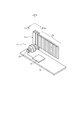
図1に示すように、画像表示装置10は、投影光学系11および瞳拡大光学系12を含んで構成される。本実施形態において、投影光学系11の光軸に沿った方向をz方向、z方向に垂直且つ互いに垂直な2方向をx方向(第1の方向)およびy方向(第2の方向)とする。図1においては、上方向をx方向とする。また、図1において、瞳拡大光学系12近傍においては、右斜め下方をy方向、左斜め下方をz方向とする。
As shown in FIG. 1, the
投影光学系11は、任意の画像に対応する画像光を無限遠に投影する。瞳拡大光学系12は、投影光学系11が投影する画像光を受光し、射出瞳を拡大して射出する。拡大された射出瞳の投影領域PA内の何れかの位置に目を合わせることにより、観察者は画像を観察可能である。
The projection
次に、投影光学系11の構成について説明する。図2に示すように、投影光学系11は、LCD13、少数のレンズより構成されるコリメータ14を含んで構成される。また、LCD13は、画像制御部16に接続される。LCD13は画像制御部16からの信号に基づいて、表示画像を表示する。なお、LCD13に代えて、有機EL素子など他の表示素子を用いても良い。コリメータ14は、LCD13の各画素から射出される拡散光を、平行光にする。コリメータ14がつくる射出瞳15は、瞳拡大光学系12の入射面に一致するように配置される。また、図1の画像制御部16は、後述するように、瞳拡大光学系12の第1の伝播光学系22及び第2の伝播光学系24が生じさせる画像の歪みを補正するように予め処理した画像信号をLCD13に出力する。
Next, the configuration of the projection
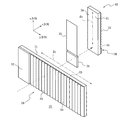
次に、瞳拡大光学系12の構成について、図3を用いて説明する。瞳拡大光学系12は、偏光子21、第1の伝播光学系22、1/2波長板23、および第2の伝播光学系24を含んで構成される。図3においては、説明のために、偏光子21、第1の伝播光学系22、1/2波長板23、および第2の伝播光学系24を大きく離間させた状態で表示されるが、実際には、図1に示すように、近接して配置される。
Next, the configuration of the pupil enlarging
偏光子21は、投影光学系11の射出瞳15および投影光学系11の間に配置され、投影光学系11から出射される画像光を受光して、S偏光を出射する。第1の伝播光学系22は、後述する第1の導光部25の第1の平面S1(図4参照)の入射領域と投影光学系11の射出瞳15が合わさるように配置され、偏光子21によりS偏光として投影される射出瞳をx方向に拡大して出射する(符号“Ex”参照)。1/2波長板23は、x方向に拡大された画像光の偏光面を90°回転させる。偏光面を90°回転させることにより、第2の伝播光学系24にS偏光で画像光を入射させることが可能である。第2の伝播光学系24は、1/2波長板23により偏光面が回転した画像光をy方向に拡大して出射する(符号“Ey”参照)。
The
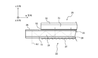
次に、第1の伝播光学系22による射出瞳の拡大機能について、第1の伝播光学系22の構成とともに説明する。図4に示すように、第1の伝播光学系22は、第1の導光部25、第1の回折素子26(第1の入力偏向部)、第1の三角プリズムアレイ27(第1の出力偏向部)、第1の偏光ビームスプリット膜28を含んで構成される。なお、第1の偏光ビームスプリット膜28は、後述するように、第1の導光部25に蒸着されており、互いに分離できない。
Next, the function of enlarging the exit pupil by the first propagation
第1の導光部25は、互いに平行且つ対向する第1の平面S1および第2の平面S2を有し、透過性を有する平板である。第1の回折素子26は、第1の導光部25の第2の平面S2の画像光の入射側端部に透明接着剤により接合されている。また、第1の導光部25の第2の平面S2の第1の回折素子26が接合されていない残りの部分には、第1の三角プリズムアレイ27が、第1の偏光ビームスプリット膜を挟んで透明接着剤により接合される。投影光学系11からの画像光は、第1の平面S1の第1の回折素子26に対向する領域に入射するので、この領域を入射領域と呼び、第1の平面S1の第1の三角プリズムアレイ27と対向する領域は、第1の導光部25を伝播する画像光が射出される領域であり、射出領域と呼ぶ。
The 1st
第1の偏光ビームスプリット膜28は、実質的に垂直な方向から入射する光を透過し、斜方から入射する光の大部分を反射するように設計された多層膜である。このような特性を、ローパス型またはバンドパス型の分光反射特性を有する薄膜は有し得る。
The first polarization
また、第1の偏光ビームスプリット膜28は、x方向に沿った位置に応じて変動する、斜入射光に対する透過率を有する。例えば、第1の偏光ビームスプリット膜28の、入射領域側の一端からの距離に応じて等比級数的に透過率が増加するように、第1の偏光ビームスプリット膜28が形成される。蒸着によってこのような膜を形成するには、例えば蒸着源からの距離が入射領域からの平面状の距離に応じて変化するように配置し、その距離の差(製膜される膜厚の差)によるそれぞれの位置において所望の反射特性をもつように予め設計することにより、成膜可能である。
The first polarization
第1の導光部25は、x方向に長く(例えば60mm)y方向に短い(例えば20mm)矩形の板状部材であり、数mm(例えば3mm)の厚み、すなわちz方向の長さを有する部材であり、材質としては石英(透明媒質)が用いられる。第1の導光部25に石英を用いることにより、第1の偏光ビームスプリット膜28を蒸着させるときの加熱に対して耐熱性を有し、硬質であるため膜応力に対して反りにくくなる利点を有する。また、第1の導光部25の第1の平面S1には、AR膜(図示せず)が形成される。AR膜は垂直な方向から入射する画像光の反射を抑制する。
The first
第1の回折素子26は、第1の導光部25の入射領域から入射した画像光を、x方向に傾けて回折させる反射型の回折素子である。第1の回折素子26は、画像光の波長に対して1次の回折方向に高い回折効率を有するように設計されている。第1の回折素子26の例としては、鋸歯状の断面を有しy方向に延びる溝をx方向に配列したブレーズド回折格子等を用いることができる。第1の回折素子26は、入射領域から入射して第1の回折素子26で回折を受けて偏向された画像光が、第1の導光部25内で第1の平面S1により全反射されるように、格子定数等のパラメータが設計される。すなわち、第1の導光部25内を伝播する画像光の第1の平面S1に対する入射角度は、臨界角より大きい。例えば、第1の導光部25を石英で形成した場合には、臨界角は43.6°である。
The first
第1の三角プリズムアレイ27は、xz断面が三角形のy方向に長い三角プリズムを、x方向に配列した形状となっている。各三角プリズムは、第2の平面S2に接する面、第2の平面S2にほぼ垂直な面、および、斜面Soにより構成される。三角プリズムは、透明な媒体、例えばアクリルより成り射出成型により形成する。また、各三角プリズムの斜面Soは、アルミが蒸着され、法線を入射領域側に向けて傾いている。斜面Soの傾きは、画像光のうち入射領域に垂直入射して、第1の回折素子26で一次回折を受け、第1の導光部25内を伝播して第1の偏向ビームスプリット膜28を透過して、第1の三角プリズムアレイ27に入射する光線が、第1の平面S1に向けて垂直に反射されるように決定される。
The first
上述のように構成および配置した第1の伝播光学系22において、図4に示すように、第1の平面S1の入射領域に垂直に入射した第1の光線b1(図4において破線で示す)は、第2の平面S2に接合された第1の回折素子26で一次回折を受けて反射し、第1の導光部25内をxz平面に平行かつ第1の平面S1に傾斜して第1の平面S1に向かう。第1の平面S1に向かった第1の光線b1は、第1の平面S1に対して臨界角を越える角度で入射して全反射される。全反射された第1の光線b1は、第2の平面S2へ向かい第2の平面S2上に形成された第1の偏光ビームスプリット膜28に斜方から入射し、所定の割合の光量だけ透過し、残りの光量は反射する。第1の偏光ビームスプリット膜28に反射された第1の光線b1は、再び第1の平面S1に臨界角を超える角度で入射し、全反射される。以後、第1の光線b1は、第1の偏光ビームスプリット膜28における一部反射と、第1の平面S1における全反射とを繰返しながら、第1の導光部25のx方向に伝播される。ただし、第1の偏光ビームスプリット膜28に入射するたびに、所定の割合で透過し、第1の三角プリズムアレイ27に出射する。
In the first propagation
第1の三角プリズムアレイ27に出射された第1の光線b1は、第1の三角プリズムアレイ27の斜面Soの反射膜により再び第1の導光部25の第2の平面S2に垂直な方向に反射される。垂直な方向に反射された第1の光線b1は、第1の導光部25を通り第1の平面S1から外部に出射される。
The first light beam b1 emitted to the first
1/2波長板23(図3参照)は、第1の平面S1の出射領域と実質的に同じサイズの形状に形成される。1/2波長板23は、第1の平面S1の出射領域と対向する位置において、空隙を設けて配置される。したがって、第1の導光部25内で臨界角以上の入射角で第1の平面S1に入射する光束は、第1の平面S1を透過すること無く、全反射が保障される。前述のように、1/2波長板23は、第1の伝播光学系22から出射する光束の偏光面を90°回転させる。
The half-wave plate 23 (see FIG. 3) is formed in a shape that is substantially the same size as the emission region of the first plane S1. The half-
第2の伝播光学系24のサイズおよび配置以外の構成は、第1の伝播光学系22と同じである。図3に示すように、第2の伝播光学系24は、第2の導光部31、第2の偏光ビームスプリット膜(図示せず)、第2の回折素子32(第2の入力偏向部)、および第2の三角プリズムアレイ33(第2の出力偏向部)を含んで構成される。第1の伝播光学系22と同様に、これらの構成部材は一体化された平板状であり、第2の伝播光学系24および第2の導光部31の幅方向(図3における“x方向”)および長さ方向(図3における“y方向”)の長さは、それぞれ、例えば50mmおよび110mmである。また、第2の伝播光学系24における第2の偏光ビームスプリット膜の長手方向(y方向)の長さは、例えば100mmである。また、第2の回折素子32のy方向の長さは、例えば10mmである。第2の導光部31、第2の偏光ビームスプリット膜、第2の回折素子32、および第2の三角プリズムアレイ33の機能は、それぞれ第1の導光部25、第1の偏光ビームスプリット膜28、第1の回折素子26、および第1の三角プリズムアレイ27と同様である。
The configuration other than the size and arrangement of the second propagation
第2の伝播光学系24は、第1の伝播光学系22の第1の平面S1の出射領域と第2の伝播光学系24の第3の平面S3の入射領域とが対向し、第2の伝播光学系24を第1の伝播光学系22に対してz方向に平行な直線を軸に90°回転させた姿勢で、配置される(図3参照)。したがって、第2の伝播光学系24は、第1の伝播光学系22から出射する画像光をy方向に拡大して出射する。このようにして、射出瞳が拡大する。
In the second propagation
次に、図4を参照して、第1の伝播光学系22の入射領域に、入射角θiで入射した第2の光線b2の光路について説明する。第2の光線b2は、第1の回折素子26により射出領域方向へ偏向され、第1の導光部25内を第1の平面S1に臨界角以上の角度で入射して全反射される。第1の平面S1で全反射された第2の光線b2は、第2の平面S2に入射し、一部の光量が第1の偏光ビームスプリット膜28を透過して、第1の三角プリズムアレイ27の斜面Soで反射される。斜面Soで反射された第2の光線b2は、第2の平面S2上の第1の偏光ビームスプリット膜28を透過して、第1の導光部25を通り、第1の平面S1から出射する。ここで、第2の光線b2は入射角θiに応じて傾斜した射出角θoで、第1の平面S1から出射する。
Next, with reference to FIG. 4, the optical path of the second light beam b2 that has entered the incident area of the first propagation
例えば、回折次数(m)を−1、画像光の波長を(λ)を532nm、第1の三角プリズムアレイ27の屈折率(n)を1.51、回折格子周期(d)を450nmとした場合、入射角θiと射出角θoとの関係は、表1のようになる。
For example, the diffraction order (m) is −1, the wavelength of the image light is (λ) is 532 nm, the refractive index (n) of the first

表1から明らかなように、入射領域における画像光の偏向に第1の回折格子素子26を用いたことによって、入射角θiよりも射出角θoの方が大きくなる。このような、射出角の拡大効果は、第1および第2の導光部25,31への入射領域および射出領域における画像光の偏向のために、双方ともにミラーやハーフミラーを用いた場合には見られない。入射領域および射出領域の双方にミラーを用いた場合は、入射角θiと射出角θoとが等しくなる。また、入射領域および射出領域の双方に回折素子を用いた場合も、入射角θiと射出角θoとは等しくなる。このように、射出角θoを拡大できることによって、入射角θiを相対的に小さくすることができる。すなわち、投影光学系11から入射する画像光の画角を小さくすることができる。
As is apparent from Table 1, the use of the first
図5(a)は、本実施の形態の投影光学系11の概略構成を示す図であり、その構成は図2を用いて説明したとおりである。ここで、θ1はLCD13から射出された画像光の広がりを示し、θ2はコリメータ14を透過後の射出瞳へ投影される画像光の画角を示す。画像表示装置が表示可能な画像の画角は、射出瞳での投影光学系11の無限遠虚像を投影する画角であるθ2と関連する。通常、画像表示装置10の表示画角と投影光学系11の画角は同じであるから、従来の画像表示装置10では図5(b)で示すように、投影光学系11の画角θ4を広げるために、コリメータ36を、収差を抑えるための多数の光学要素を配置して構成している。これに対して、本発明の画像表示装置10は、瞳拡大光学系12の第1の伝播光学系22および第2の伝播光学系24が、射出角を広げる効果、すなわち射出瞳の画角を広げ、入射した画像光よりも大きな視野角の画像を表示することが可能になる。よって、図5(a)のようにレンズ枚数の削減、あるいは、焦点距離の縮小による小型化が可能になる。
FIG. 5A is a diagram illustrating a schematic configuration of the projection
また、図6(a)は、図1の瞳拡大光学系12の画像光の伝播を説明する図であり、図6(b)は、従来例の瞳拡大光学系12aの画像光の伝播を説明する図である。これらの図は、瞳拡大光学系12、12aをz方向に見た図となっている。また、図6(b)において、第1実施の形態と同様の機能を有する構成要素には、第1実施の形態と同一の符号に「a」を付して示している。
FIG. 6A is a diagram for explaining the propagation of the image light of the pupil enlarging
従来の瞳拡大光学系12aでは、投影光学系からの画像光の画角が大きいために、第1の伝播光学系22aを伝播する画像光の光束は、図6(b)の最も+y方向へシフトする光束p4、最も−y方向にシフトする光束p5で示すように、y方向に大きくシフトする成分を有している。このため、光線のケラレや画像のムラを生じさせないために、第1の伝播光学系22aの画像光入射領域A3(すなわち、第1の導光部25aの入射領域)をy方向に広く取り、+y方向および−y方向の画像光が重なる範囲でy方向の幅を限定して、第1の伝播光学系22aの射出領域A4(すなわち、第1の導光部25aの射出領域)を設定する必要があった。その結果、投影光学系11から入射した画像光の多くを、第1の伝播光学系22で失っていた。
In the conventional pupil enlarging optical system 12a, since the angle of view of the image light from the projection optical system is large, the luminous flux of the image light propagating through the first propagation
これに対して、本実施の形態の瞳拡大光学系12では、投影光学系11からの画像光の画角が狭く、第1の導光部25を伝播するy方向の画角は投影光学系11からの画像光の画角に等しいため(第1の伝播光学系22において射出角の拡大効果はx方向のみであるため)、図6(a)に示すように、第1の伝播光学系22を伝播する画像光の光束は、最も+y方向にシフトする光束p1および最も−y方向にシフトする光束p2ともに、y方向にシフトする量は、図6(b)に比べ相対的に小さい。このため、第1の伝播光学系22の画像光入射領域A1(すなわち、第1の導光部25の入射領域)を、小さくすることができる。その結果、第1の伝播光学系22を小型に構成することが可能になる。さらに、投影光学系11から入射した画像光を、第1の伝播光学系22で失うことなく、高い効率で第2伝播光学系24に光束p3として伝播させることができる。さらに、瞳拡大光学系12の入射瞳が小さくても良いので、投影光学系11をさらに小型に構成することができる。
On the other hand, in the pupil enlarging
ここで、再び表1を参照すると、入射角θiと射出角θoとの関係は非線形性を有している。このことは、LCD13に表示される画像が、本願の第1の伝播光学系22および第2の伝播光学系24を伝播することによって、歪みを生じることを意味する。そこで、図1の画像制御部16は、LCD13に表示する画像の画像信号として、これら第1の伝播光学系22および第2の伝播光学系24により生じる歪みを補正するように、予め反対の歪みを与えた画像信号を出力する。このようにすることによって、歪みのない画像表示が可能となる。なお、歪みを補正する方法はこれに限られず、例えば、画像制御部16を設けることに代えて、第1の伝播光学系22および第2の伝播光学系24により生じる歪みに応じて、LCDの画素を非線形に配列することによって、歪みを補正することもできる。
Here, referring to Table 1 again, the relationship between the incident angle θi and the exit angle θo has nonlinearity. This means that the image displayed on the
以上説明したように、本実施の形態によれば、第1の伝播光学系22および第2の伝播光学系24において、入射側の偏向を回折により行い、射出側の偏向を反射によりおこなうようにしたので、画像表示装置10の表示画角の大きさを確保しながら、投影光学系11の部品点数を削減し小型化することができる。
As described above, according to the present embodiment, in the first propagation
なお、上記第1実施の形態では、投影光学系11でLCD13の画像を投影していたが、投影光学系11はMEMSミラーを採用した構成も可能である。この場合の投影光学系の構成、作用、効果を、図7を用いて説明する。投影光学系以外の構成は、第1実施の形態と同様である。
In the first embodiment, the image on the
図7の投影光学系は、光源37、MEMSミラー38、ビームエキスパンダ39を含んで構成される。光源37は、レーザ光源であり高速にON/OFFを切替えることができる。MEMSミラー38は高周波数で繰返し2次元走査を行うミラー素子である。光源37は、MEMSミラー38のミラー面に合わせてビーム径を拡大して、MEMSミラー38に照射する。ビームエキスパンダ39は、MEMSミラー38と瞳拡大光学系12との間に配置され、MEMSミラー38で反射された光線を拡大して、瞳拡大光学系12の入射瞳、すなわち、第1の導光部25の入射領域に伝達する。MEMSミラー38と、第1の導光部25の入射領域とは、光学的に共役関係にある。
The projection optical system in FIG. 7 includes a
光源37は、図示しない制御装置によって制御され、MEMSミラー38の傾動に応じて、表示すべき画像に対応した発光タイミングで発光を行う。ビームエキスパンダ39は、第1の導光部25の入射領域に対応して、MEMSミラー38で反射されるビーム径を拡大する。第1の導光部25の入射領域に入射した画像光は、第1実施の形態で説明したように、瞳拡大光学系12によって射出瞳が拡大され、観察者に向けて射出される。
The
ここで、図7の投影光学系を用いた場合、ビームエキスパンダ39でビーム径を拡大すると、入射角θ5に対してビームエキスパンダからの画像光の射出角θ6が縮小する。このため、従来の画像表示装置であれば、画像表示装置10で大きな画角を得るためには、MEMSミラー38を大型化する必要があった。しかし、MEMSミラー38のミラー面積を大きくすると、一般に、ミラー走査の周波数やミラーの振れ角を大きくすることができない。
Here, when the projection optical system of FIG. 7 is used, when the beam diameter is enlarged by the
一方、本発明では、瞳拡大光学系12に入射する画像光の入射画角が、第1および第2の伝播光学系22、24で拡大され射出されるので、投影光学系で大きな面積のMEMSミラーを用いたり、MEMSミラーの振れ角を大きくしたりする必要が無い。したがって、投影光学系を小型に構成することが可能になる。さらに、高周波数でMEMSミラーを走査することができるので、フレームレートが高い画像を表示することが可能になる。
On the other hand, in the present invention, since the incident field angle of the image light incident on the pupil enlarging
(第2実施の形態)
図8は、第2実施の形態に係る画像表示装置の概略構成を示す図であり、図8(a)は正面図、図8(b)は上面図である。第2の実施形態に係る画像表示装置は、第1の実施とは異なり、伝播光学系42(第1の伝播光学系)によりx方向のみに射出瞳を拡大する。
(Second Embodiment)
8A and 8B are diagrams showing a schematic configuration of the image display apparatus according to the second embodiment. FIG. 8A is a front view and FIG. 8B is a top view. Unlike the first embodiment, the image display apparatus according to the second embodiment enlarges the exit pupil only in the x direction by the propagation optical system 42 (first propagation optical system).
投影光学系41は、光源45とMEMSミラー46とビームエキスパンダ47とを備える。この構成は、図7の投影光学系と同様なので説明を省略する。伝播光学系42は、導光部48、回折素子49、三角プリズムアレイ50、偏光ビームスプリット膜51により構成される。導光部48は、第1実施の形態の第1の導光部25と同様の平板状の部材である。また、回折素子49も、第1実施の形態の第1の回折素子26と同様に、導光部48の画像光の入射領域に対向する面(第2の平面S2)の入射側端部に設けられ、同様の機能を有している。さらに、偏光ビームスプリット膜51と三角プリズムアレイ50は、第1実施の形態の第1の偏光ビームスプリット膜28および第1の三角プリズムアレイ27と同様の形状、特性を有しているが、第1実施の形態とは異なり導光部48の画像光の入射側の面(第1の平面S1)の入射領域以外の部分に設けられている。なお、投影光学系41から伝播光学系42に入射する画像光はS偏光である。投影光学系41と伝播光学系42との間には、図示しない偏光子が配置しても良い。
The projection
以上のような構成によって、投影光学系41から射出された画像光は、導光部48の第の平面S1から導光部48に入射し、第2の平面S2に接合された回折素子49の回折面で回折を受け、導光部48内をx方向に伝播される。導光部48内で第1の平面に向けて回折された画像光は、一部の光量が第1の平面S1上の偏光ビームスプリット膜51を透過して、三角プリズムアレイ50で第1の平面S1に垂直な方向に反射され、導光部48内を通り第2の平面S2より射出される。また、偏光ビームスプリット膜51で反射された画像光は、導光部48内をx方向に対して傾斜して進み、第2の平面S2で再び全反射され第1の平面方向へ進み、以下これを繰り返す。
With the configuration as described above, the image light emitted from the projection
これによって、導光部48の第2の平面S2から、x方向に射出瞳が拡大された画像光が射出される。このように、一方向に画像光を伝播する伝播光学系42を用いた場合でも、画像光の伝播方向に瞳を拡大する効果がある。さらに、導光部48の入射側の画像光の偏向に回折素子を用い、射出側の偏向にミラー面として機能する三角プリズムアレイ50を用いたので、第1実施の形態と同様に入射光の画角を拡大して射出する効果がある。
As a result, image light whose exit pupil is enlarged in the x direction is emitted from the second plane S2 of the
図9は、図8(a)の伝播光学系の入射部分を画像光の経路とともに示す上面図である。第1の光線b1は、導光部48に垂直に入射する画像光を示し、第2の光線b2は入射角θiで入射する画像光を示している。第2の光線b2が導光部48から射出される際の射出角をθoとするとき、入射角θiと射出角θoとの関係は、表1のようになる。
FIG. 9 is a top view showing an incident portion of the propagation optical system of FIG. 8A together with a path of image light. The first light beam b1 indicates image light incident perpendicularly to the
表2から解るように、導光部48の入射側の面と射出側の面とが異なる場合でも、射出角θoは、入射角θiよりも大きくなっている。したがって、入射角θiを相対的に小さい角度にすることができ、投影光学系41を小型化することができる。また、MEMSミラー46は小型で良いので、高周波数で走査させることが可能になる。
As can be seen from Table 2, even when the incident-side surface and the exit-side surface of the
なお、このような一次元方向に瞳を拡大する伝播光学系としては、種々の態様のものが存在する。以下にその態様の例を説明する。 There are various types of propagation optical systems that expand the pupil in such a one-dimensional direction. The example of the aspect is demonstrated below.
図10は、伝播光学系の変形例を示している。この伝播光学系の構成では、導光部52への画像光の入射側の第1の平面S1に透過型の回折素子53を接続している。さらに、導光部52の画像光の入射側の第1の平面S1に偏光ビームスプリット膜55と三角プリズムアレイ54とを設けている。これにより、画像光は第1の平面S1に入射し、第2の平面S2から射出される。
FIG. 10 shows a modification of the propagation optical system. In this configuration of the propagation optical system, a transmission type
図11は、伝播光学系の他の変形例を示す図である。この伝播光学系の構成によれば、導光部56の画像光の入射側の第1の平面S1に対向する第2の平面S2に、画像光の入射領域に対向して反射型の回折素子57が設けられる。また、第2の平面S2には偏光ビームスプリット膜59が蒸着され、さらにその上に研磨面により構成された三角プリズムアレイ58が配列される。この三角プリズムアレイ58の斜面は、第1、第2実施の形態の三角プリズムアレイとは異なり、アルミ蒸着されず画像光を透過させるように構成されている。導光部の第2の平面S2に入射して偏光ビームスプリット膜59を透過した一部の画像光は、三角プリズムの斜面による屈折を受けて偏向され、第2の平面と略垂直方向に射出される。
FIG. 11 is a diagram showing another modification of the propagation optical system. According to this configuration of the propagation optical system, the reflection type diffractive element faces the incident area of the image light on the second plane S2 facing the first plane S1 of the
図12は、伝播光学系の更なる変形例を示す図である。この伝播光学系の構成によれば、導光部60の画像光の入射側の第1の平面S1の入射領域を斜めに切り欠き、法線をx方向に傾けるように傾斜させた斜面とし、該斜面上に透過型の回折素子61が設けられる。また、第1の平面S1の他の部分には偏光ビームスプリット膜63が蒸着され、さらにその上に三角プリズムアレイ62が接続される。この伝播光学系に入射する画像光は、斜面に形成された回折素子61による回折を受けて偏向され、第2実施の形態と同様に導光部60内を伝播しつつ、第2の平面S2から第2の平面S2に略垂直方向に射出される。
FIG. 12 is a diagram showing a further modification of the propagation optical system. According to the configuration of this propagation optical system, the incident area of the first plane S1 on the incident side of the image light of the
(第3実施の形態)
第2実施の形態に示した、画像光の入射面と射出面とが異なる透過型の伝播光学系を2つ組み合わせるようにして、第1実施の形態のようなx方向およびy方向に瞳を拡大する瞳拡大光学系を構成することも可能である。図13はこのようにして構成した、第3実施の形態の瞳拡大光学系の断面を画像光の光路とともに示す図である。図13の構成は、第1実施の形態の瞳拡大光学系12の構成と類似するので、同様の構成要素には同一の符号を付している。同一の符号を付した構成要素は、特に説明しない限り第1実施の形態と同様の構成となっている。
(Third embodiment)
By combining two transmission type propagation optical systems having different incident surfaces and exit surfaces for image light as shown in the second embodiment, the pupil is placed in the x and y directions as in the first embodiment. It is also possible to configure an enlarged pupil enlarging optical system. FIG. 13 is a diagram showing a cross section of the pupil enlarging optical system of the third embodiment configured as described above together with the optical path of image light. Since the configuration of FIG. 13 is similar to the configuration of the pupil enlarging
本実施の形態では、第1の伝播光学系22および第2の伝播光学系24は、図9に示した伝播光学系48と同様の入射面と射出面とが異なる透過型の伝播光学系である。第1の伝播光学系22と第2の伝播光学系24との間には、1/2波長板23が設けられる。第1の伝播光学系22の第1の導光部25は、第2実施の形態の図9の導光部48とは、第1の偏光ビームスプリット膜28が、第1の導光部25の画像光の入射側の面より内側に形成されている点においてのみ異なっている。このような第1の導光部25は、2枚の透明な板状の部材の一方の部材の一面に偏光ビームスプリット膜を蒸着し、この偏向ビームスプリット面が形成された面に他方の部材を透明接着材などで接合することにより形成できる。
In the present embodiment, the first propagation
第1の導光部25に入射した画像光は、第1の回折格子26で回折され、第1の偏光ビームスプリット膜28で一部の光量が透過し、残りの光量が反射され、第2の平面S2では全反射される。そして、第1の偏向ビームスプリット膜28と第2の平面S2との間を、反射を繰り返しながらx方向に伝播される。よって、本実施の形態では、第1の偏光ビームスプリット膜28が形成された平面が、第1の平面S1に相当する。第1の偏向ビームスプリット膜28を透過した画像光は、第1の三角プリズムアレイ27で反射され、第1の導光部25内を通過して第2の平面S2から、第2の平面に略垂直方向に射出される。
The image light incident on the first
第2の平面S2から射出された画像光は、1/2波長板23で偏光方向を90度回転され、S偏光として第2の伝播光学系24に入射する。第2の伝播光学系24も、大きさ及び向きを除き本実施の形態の第1の伝播光学系22と同様に構成される。これにより、第2の伝播光学系24に入射し第2の回折素子32で回折された画像光は、第2の導光部31内で反射を繰り返しながら、y方向に画像光を伝播しながら、入射側の面に対向する第4の平面S4から射出される。
The image light emitted from the second plane S2 is rotated by 90 degrees in the polarization direction by the half-
以上説明したように、本実施の形態によれば、第1実施の形態と同様に、x方向およびy方向に射出瞳を拡大した、画像表示装置を提供することができる。そして、第1の伝播光学系22および第2の伝播光学系24において、入射側の偏向を回折により行い、射出側の偏向を反射により行うようにしたので、画像表示装置の表示画角を確保しながら投影光学系の部品点数を削減したり、小型化したりすることができる。
As described above, according to the present embodiment, it is possible to provide an image display device in which the exit pupil is enlarged in the x direction and the y direction, as in the first embodiment. In the first propagation
本発明を諸図面や実施例に基づき説明してきたが、当業者であれば本開示に基づき種々の変形や修正を行うことが容易であることに注意されたい。従って、これらの変形や修正は本発明の範囲に含まれることに留意されたい。例えば、各実施形態に記載された各構成要素の寸法、形状、配置等は例示であって、本発明の範囲内で種々の寸法、形状、配置等をとることができる。第1および第2の伝播光学系は、例示のものに限られず、入射側の偏向に回折素子を用い射出側の偏向に反射や屈折素子を用いたものであれば本発明の範囲に含まれる。 Although the present invention has been described based on the drawings and examples, it should be noted that those skilled in the art can easily make various modifications and corrections based on the present disclosure. Therefore, it should be noted that these variations and modifications are included in the scope of the present invention. For example, the dimensions, shapes, arrangements, and the like of the constituent elements described in the embodiments are examples, and various dimensions, shapes, arrangements, and the like can be taken within the scope of the present invention. The first and second propagating optical systems are not limited to those illustrated, and any diffractive element may be used for incident side deflection and a reflective or refracting element may be used for exit side deflection. .
10 画像表示装置
11 投影光学系
12 瞳拡大光学系
13 LCD
14 コリメータ
15 射出瞳
16 画像制御部
21 偏光子
22 第1の伝播光学系
23 1/2波長板
24 第2の伝播光学系
25 第1の導光部
26 第1の回折素子
27 第1の三角プリズムアレイ
28 第1の偏光ビームスプリット膜
31 第2の導光部
32 第2の回折素子
33 第2の三角プリズムアレイ
36 コリメータ
37、45 光源
38、46 MEMSミラー
39、47 ビームエキスパンダ
41 投影光学系
42 伝播光学系
48,52,56,60 導光部
49,53,57,61 回折素子
50,54,58,62, 三角プリズムアレイ
51,55,59,63 偏光ビームスプリット膜
DESCRIPTION OF
DESCRIPTION OF
Claims (7)
第1の伝播光学系と、を備え、
前記第1の伝播光学系が、
前記投影光学系から射出された画像光を回折させる第1の入力偏向部と、
互いに平行且つ対向する第1の平面および第2の平面を有する板状に形成され、前記第1の平面および前記第2の平面の間で、前記第1の入力偏向部で偏向された前記画像光を、反射を繰返しながら第1の方向に伝播させる第1の導光部と、
前記第1の導光部を伝播する画像光の一部を前記第1の平面に実質的に垂直な方向に、反射または屈折により偏向させる第1の出力偏向部と、を備え、
前記第1の入力偏向部と前記第1の出力偏向部とは、前記画像光が前記第1の伝播光学系へ入射する入射角に対して、該画像光が前記第1の出力偏向部により偏向され前記第1の伝播光学系から射出する射出角を拡大し、前記入射角と前記射出角との関係は非線形性を有する
画像表示装置。 A projection optical system that projects image light corresponding to an arbitrary image to infinity;
A first propagation optical system,
The first propagation optical system is
A first input deflection unit that diffracts image light emitted from the projection optical system;
The image formed in a plate shape having a first plane and a second plane that are parallel to and opposed to each other, and is deflected by the first input deflection unit between the first plane and the second plane. A first light guide that propagates light in a first direction while repeating reflection;
A first output deflection unit that deflects a part of the image light propagating through the first light guide unit in a direction substantially perpendicular to the first plane by reflection or refraction,
The first input deflection unit and the first output deflection unit are configured such that the image light is incident on the first propagation optical system by the first output deflection unit with respect to an incident angle at which the image light is incident on the first propagation optical system. An image display apparatus that enlarges an exit angle that is deflected and exits from the first propagation optical system, and the relationship between the entrance angle and the exit angle has nonlinearity.
請求項1に記載の画像表示装置。 The projection optical system includes an incident angle at which the image light is incident on the first propagation optical system, and an emission angle at which the image light is deflected by the first output deflection unit and is emitted from the first propagation optical system. The image display apparatus according to claim 1, wherein the corrected image light is projected on the basis of the non-linearity between the image display apparatus and the image display apparatus.
前記第2の伝播光学系は、
前記第1の出力偏向部により偏向され、前記第1の伝播光学系から射出された前記画像光を回折させる第2の入力偏向部と、
互いに平行且つ対向する第3の平面および第4の平面を有する板状に形成され、前記第3の平面および前記第4の平面の間で、前記第2の入力偏向部で偏向された前記画像光を、反射を繰返しながら前記第1の方向に実質的に直交する第2の方向に伝播させる第2の導光部と、
前記第2の導光部を伝播する前記画像光の一部を前記第3の平面に実質的に垂直な方向に、反射または屈折により偏向させる第2の出力偏向部と、を備えている
請求項1に記載の画像表示装置。 A second propagation optical system;
The second propagation optical system includes:
A second input deflection unit that diffracts the image light deflected by the first output deflection unit and emitted from the first propagation optical system;
The image formed in a plate shape having a third plane and a fourth plane that are parallel to and opposed to each other, and is deflected by the second input deflection unit between the third plane and the fourth plane. A second light guide that propagates light in a second direction substantially orthogonal to the first direction while repeating reflection;
A second output deflecting unit configured to deflect a part of the image light propagating through the second light guide unit by reflection or refraction in a direction substantially perpendicular to the third plane. Item 4. The image display device according to Item 1.
請求項3に記載の画像表示装置。 The projection optical system includes an incident angle at which the image light is incident on the first propagation optical system, and an exit angle at which the image light is deflected by the second output deflection unit and is emitted from the second propagation optical system. The image display apparatus according to claim 3, wherein the corrected image light is projected based on the non-linearity of the image.
請求項1から4の何れか一項に記載の画像表示装置。 5. The image display device according to claim 1, wherein the first input deflection unit includes a diffraction grating pattern periodically arranged in the first direction. 6.
第1の伝播光学系と、を備え、
前記第1の伝播光学系が、
前記投影光学系から射出された画像光を、回折させる第1の入力偏向部と、
互いに平行且つ対向する第1の平面および第2の平面を有する板状に形成され、前記第1の平面および前記第2の平面の間で、前記第1の入力偏向部で偏向された前記画像光を、反射を繰返しながら第1の方向に伝播させる第1の導光部と、
前記第1の導光部を伝播する画像光の一部を前記第1の平面に実質的に垂直な方向に、回折させること無く反射または屈折により偏向させる第1の出力偏向部と
を備え、
前記第1の入力偏向部と前記第1の出力偏向部とは、前記投影光学系から射出され前記第1の伝播光学系に入射する画像光の入射角に対して、前記第1の出力偏向部により偏向され、前記第1の伝播光学系から射出される画像光の射出角を広げるように構成される画像表示装置。 A projection optical system that projects image light corresponding to an arbitrary image to infinity;
A first propagation optical system,
The first propagation optical system is
A first input deflection unit that diffracts image light emitted from the projection optical system;
The image formed in a plate shape having a first plane and a second plane that are parallel to and opposed to each other, and is deflected by the first input deflection unit between the first plane and the second plane. A first light guide that propagates light in a first direction while repeating reflection;
A first output deflection unit configured to deflect a part of image light propagating through the first light guide unit by reflection or refraction without being diffracted in a direction substantially perpendicular to the first plane ;
Equipped with a,
The first input deflection unit and the first output deflection unit are configured to output the first output deflection with respect to an incident angle of image light emitted from the projection optical system and incident on the first propagation optical system. An image display device configured to widen an emission angle of image light deflected by the unit and emitted from the first propagation optical system .
第1の伝播光学系と、
第2の伝播光学系と、
を備え、
前記第1の伝播光学系が、
前記投影光学系から射出された画像光を、回折させる第1の入力偏向部と、
互いに平行且つ対向する第1の平面および第2の平面を有する板状に形成され、前記第1の平面および前記第2の平面の間で、前記第1の入力偏向部で偏向された前記画像光を、反射を繰返しながら第1の方向に伝播させる第1の導光部と、
前記第1の導光部を伝播する画像光の一部を前記第1の平面に実質的に垂直な方向に、回折させること無く反射または屈折により偏向させる第1の出力偏向部と
を備え、
前記第2の伝播光学系は、
前記第1の出力偏向部により偏向され、前記第1の伝播光学系から射出された前記画像光を回折させる第2の入力偏向部と、
互いに平行且つ対向する第3の平面および第4の平面を有する板状に形成され、前記第3の平面および前記第4の平面の間で、前記第2の入力偏向部で偏向された前記画像光を、反射を繰返しながら前記第1の方向に実質的に直交する第2の方向に伝播させる第2の導光部と、
前記第2の導光部を伝播する前記画像光の一部を前記第3の平面に実質的に垂直な方向に、回折させること無く反射または屈折により偏向させる第2の出力偏向部と、
を備える画像表示装置。 A projection optical system that projects image light corresponding to an arbitrary image to infinity;
A first propagation optical system;
A second propagation optical system;
With
The first propagation optical system is
A first input deflection unit that diffracts image light emitted from the projection optical system;
The image formed in a plate shape having a first plane and a second plane that are parallel to and opposed to each other, and is deflected by the first input deflection unit between the first plane and the second plane. A first light guide that propagates light in a first direction while repeating reflection;
A first output deflection unit configured to deflect a part of image light propagating through the first light guide unit by reflection or refraction without being diffracted in a direction substantially perpendicular to the first plane;
With
The second propagation optical system includes:
A second input deflection unit that diffracts the image light deflected by the first output deflection unit and emitted from the first propagation optical system;
The image formed in a plate shape having a third plane and a fourth plane that are parallel to and opposed to each other, and is deflected by the second input deflection unit between the third plane and the fourth plane. A second light guide that propagates light in a second direction substantially orthogonal to the first direction while repeating reflection;
A second output deflecting unit configured to deflect a part of the image light propagating through the second light guide unit by reflection or refraction without diffracting in a direction substantially perpendicular to the third plane;
An image display device comprising:
Priority Applications (3)
| Application Number | Priority Date | Filing Date | Title |
|---|---|---|---|
| JP2014066604A JP6442149B2 (en) | 2014-03-27 | 2014-03-27 | Image display device |
| PCT/JP2015/000877 WO2015145963A1 (en) | 2014-03-27 | 2015-02-23 | Image display device |
| US15/253,793 US20160370693A1 (en) | 2014-03-27 | 2016-08-31 | Image display device |
Applications Claiming Priority (1)
| Application Number | Priority Date | Filing Date | Title |
|---|---|---|---|
| JP2014066604A JP6442149B2 (en) | 2014-03-27 | 2014-03-27 | Image display device |
Publications (3)
| Publication Number | Publication Date |
|---|---|
| JP2015191032A JP2015191032A (en) | 2015-11-02 |
| JP2015191032A5 JP2015191032A5 (en) | 2017-04-20 |
| JP6442149B2 true JP6442149B2 (en) | 2018-12-19 |
Family
ID=54194521
Family Applications (1)
| Application Number | Title | Priority Date | Filing Date |
|---|---|---|---|
| JP2014066604A Expired - Fee Related JP6442149B2 (en) | 2014-03-27 | 2014-03-27 | Image display device |
Country Status (3)
| Country | Link |
|---|---|
| US (1) | US20160370693A1 (en) |
| JP (1) | JP6442149B2 (en) |
| WO (1) | WO2015145963A1 (en) |
Families Citing this family (40)
| Publication number | Priority date | Publication date | Assignee | Title |
|---|---|---|---|---|
| US10073264B2 (en) | 2007-08-03 | 2018-09-11 | Lumus Ltd. | Substrate-guide optical device |
| US10261321B2 (en) | 2005-11-08 | 2019-04-16 | Lumus Ltd. | Polarizing optical system |
| IL232197B (en) | 2014-04-23 | 2018-04-30 | Lumus Ltd | Compact head-mounted display system |
| IL235642B (en) | 2014-11-11 | 2021-08-31 | Lumus Ltd | Compact head-mounted display system protected by a hyperfine structure |
| EP3062142B1 (en) | 2015-02-26 | 2018-10-03 | Nokia Technologies OY | Apparatus for a near-eye display |
| JP6597196B2 (en) * | 2015-11-05 | 2019-10-30 | セイコーエプソン株式会社 | Virtual image display measures |
| CN106101512B (en) * | 2016-08-11 | 2021-08-13 | 李炳华 | Hemispherical multi-angle intelligent shooting system and method |
| JP2018054671A (en) * | 2016-09-26 | 2018-04-05 | セイコーエプソン株式会社 | Beam diameter enlargement device, and display device |
| KR102528646B1 (en) * | 2016-10-09 | 2023-05-03 | 루머스 리미티드 | Aperture multiplier using a rectangular waveguide |
| EP3371635B1 (en) | 2016-11-08 | 2022-05-04 | Lumus Ltd. | Light-guide device with optical cutoff edge and corresponding production methods |
| US10650552B2 (en) | 2016-12-29 | 2020-05-12 | Magic Leap, Inc. | Systems and methods for augmented reality |
| EP3343267B1 (en) | 2016-12-30 | 2024-01-24 | Magic Leap, Inc. | Polychromatic light out-coupling apparatus, near-eye displays comprising the same, and method of out-coupling polychromatic light |
| US10409066B2 (en) * | 2017-01-19 | 2019-09-10 | Coretronic Corporation | Head-mounted display device with waveguide elements |
| KR102338472B1 (en) | 2017-02-22 | 2021-12-14 | 루머스 리미티드 | light guide optical assembly |
| WO2018173035A1 (en) | 2017-03-22 | 2018-09-27 | Lumus Ltd. | Overlapping facets |
| IL251645B (en) | 2017-04-06 | 2018-08-30 | Lumus Ltd | Light-guide optical element and method of its manufacture |
| WO2018213388A1 (en) * | 2017-05-16 | 2018-11-22 | Magic Leap, Inc. | Systems and methods for mixed reality |
| KR20200022508A (en) * | 2017-07-13 | 2020-03-03 | 시리얼 테크놀로지즈 에스.에이. | Display device for expanding the field of view |
| US10578870B2 (en) | 2017-07-26 | 2020-03-03 | Magic Leap, Inc. | Exit pupil expander |
| DE102017122353A1 (en) * | 2017-09-26 | 2019-03-28 | Carl Zeiss Ag | Optical transmission device for transmitting a source image |
| CN111448497B (en) | 2017-12-10 | 2023-08-04 | 奇跃公司 | Antireflective coating on optical waveguides |
| AU2018392482A1 (en) | 2017-12-20 | 2020-07-02 | Magic Leap, Inc. | Insert for augmented reality viewing device |
| US10551544B2 (en) | 2018-01-21 | 2020-02-04 | Lumus Ltd. | Light-guide optical element with multiple-axis internal aperture expansion |
| CN112136152A (en) | 2018-03-15 | 2020-12-25 | 奇跃公司 | Image correction caused by deformation of components of a viewing device |
| WO2019224764A1 (en) | 2018-05-23 | 2019-11-28 | Lumus Ltd. | Optical system including light-guide optical element with partially-reflective internal surfaces |
| US11885871B2 (en) | 2018-05-31 | 2024-01-30 | Magic Leap, Inc. | Radar head pose localization |
| US11579441B2 (en) | 2018-07-02 | 2023-02-14 | Magic Leap, Inc. | Pixel intensity modulation using modifying gain values |
| US11856479B2 (en) | 2018-07-03 | 2023-12-26 | Magic Leap, Inc. | Systems and methods for virtual and augmented reality along a route with markers |
| WO2020023545A1 (en) | 2018-07-24 | 2020-01-30 | Magic Leap, Inc. | Temperature dependent calibration of movement detection devices |
| WO2020023543A1 (en) | 2018-07-24 | 2020-01-30 | Magic Leap, Inc. | Viewing device with dust seal integration |
| EP3831058A4 (en) | 2018-08-02 | 2022-04-20 | Magic Leap, Inc. | A viewing system with interpupillary distance compensation based on head motion |
| EP3830631A4 (en) | 2018-08-03 | 2021-10-27 | Magic Leap, Inc. | Unfused pose-based drift correction of a fused pose of a totem in a user interaction system |
| EP3939030A4 (en) | 2019-03-12 | 2022-11-30 | Magic Leap, Inc. | Registration of local content between first and second augmented reality viewers |
| JP2022538957A (en) | 2019-06-27 | 2022-09-07 | ルーマス リミテッド | Apparatus and method for eye tracking based on imaging the eye through light guide optics |
| US11737832B2 (en) | 2019-11-15 | 2023-08-29 | Magic Leap, Inc. | Viewing system for use in a surgical environment |
| CN114746797A (en) | 2019-12-08 | 2022-07-12 | 鲁姆斯有限公司 | Optical system with compact image projector |
| US11860369B2 (en) | 2021-03-01 | 2024-01-02 | Lumus Ltd. | Optical system with compact coupling from a projector into a waveguide |
| US11822088B2 (en) | 2021-05-19 | 2023-11-21 | Lumus Ltd. | Active optical engine |
| IL309966B1 (en) | 2021-07-04 | 2024-03-01 | Lumus Ltd | Display with stacked light-guide elements providing different parts of field of view |
| TW202309570A (en) | 2021-08-23 | 2023-03-01 | 以色列商魯姆斯有限公司 | Methods of fabrication of compound light-guide optical elements having embedded coupling-in reflectors |
Family Cites Families (22)
| Publication number | Priority date | Publication date | Assignee | Title |
|---|---|---|---|---|
| ATE254291T1 (en) * | 1998-04-02 | 2003-11-15 | Elop Electrooptics Ind Ltd | OPTICAL HOLOGRAPHIC DEVICES |
| EP1430351B1 (en) * | 2001-09-25 | 2006-11-29 | Cambridge Flat Projection Displays Limited | Flat-panel projection display |
| IL148804A (en) * | 2002-03-21 | 2007-02-11 | Yaacov Amitai | Optical device |
| US20060132914A1 (en) * | 2003-06-10 | 2006-06-22 | Victor Weiss | Method and system for displaying an informative image against a background image |
| WO2006025317A1 (en) * | 2004-08-31 | 2006-03-09 | Nikon Corporation | Light flux expanding optical system and imag display unit |
| EP1922580B1 (en) * | 2005-09-07 | 2009-11-04 | BAE Systems PLC | A projection display with a rod-like, rectangular cross-section waveguide and a plate-like waveguide, each of them having a diffraction grating |
| WO2007029032A1 (en) * | 2005-09-07 | 2007-03-15 | Bae Systems Plc | A projection display with two plate-like, co-planar waveguides including gratings |
| WO2008148927A1 (en) * | 2007-06-04 | 2008-12-11 | Nokia Corporation | A diffractive beam expander and a virtual display based on a diffractive beam expander |
| WO2009077772A1 (en) * | 2007-12-18 | 2009-06-25 | Bae Systems Plc | Improvemements in or relating to display projectors |
| EP2225601A1 (en) * | 2007-12-18 | 2010-09-08 | BAE Systems PLC | Improvements in or relating to projection displays |
| WO2009127849A1 (en) * | 2008-04-14 | 2009-10-22 | Bae Systems Plc | Improvements in or relating to waveguides |
| US7570859B1 (en) * | 2008-07-03 | 2009-08-04 | Microvision, Inc. | Optical substrate guided relay with input homogenizer |
| US7613373B1 (en) * | 2008-07-03 | 2009-11-03 | Microvision, Inc. | Substrate guided relay with homogenizing input relay |
| JP4706737B2 (en) * | 2008-08-18 | 2011-06-22 | ソニー株式会社 | Image display device |
| US8493662B2 (en) * | 2008-09-16 | 2013-07-23 | Bae Systems Plc | Waveguides |
| EP2376970A1 (en) * | 2008-12-12 | 2011-10-19 | BAE Systems PLC | Improvements in or relating to waveguides |
| JP5929031B2 (en) * | 2011-08-05 | 2016-06-01 | セイコーエプソン株式会社 | Virtual image display device |
| JP5901192B2 (en) * | 2011-09-13 | 2016-04-06 | オリンパス株式会社 | Optical mechanism |
| JP5884502B2 (en) * | 2012-01-18 | 2016-03-15 | ソニー株式会社 | Head mounted display |
| WO2013135943A1 (en) * | 2012-03-16 | 2013-09-19 | Nokia Corporation | Image providing apparatus and method |
| JP5929567B2 (en) * | 2012-07-03 | 2016-06-08 | ソニー株式会社 | Image signal processing apparatus, image signal processing method, and program |
| JP6241762B2 (en) * | 2013-03-28 | 2017-12-06 | パナソニックIpマネジメント株式会社 | Image display device |
-
2014
- 2014-03-27 JP JP2014066604A patent/JP6442149B2/en not_active Expired - Fee Related
-
2015
- 2015-02-23 WO PCT/JP2015/000877 patent/WO2015145963A1/en active Application Filing
-
2016
- 2016-08-31 US US15/253,793 patent/US20160370693A1/en not_active Abandoned
Also Published As
| Publication number | Publication date |
|---|---|
| WO2015145963A1 (en) | 2015-10-01 |
| JP2015191032A (en) | 2015-11-02 |
| US20160370693A1 (en) | 2016-12-22 |
Similar Documents
| Publication | Publication Date | Title |
|---|---|---|
| JP6442149B2 (en) | Image display device | |
| JP7424635B2 (en) | Optical system including light-guiding optical element with two-dimensional expansion | |
| AU2022202969B2 (en) | Aperture multiplier using a rectangular waveguide | |
| CN111183393B (en) | Augmented reality display | |
| WO2015136850A1 (en) | Display device | |
| KR102350385B1 (en) | Exit pupil expanding diffractive optical waveguiding device | |
| CN107209372B (en) | Display system | |
| JP6265805B2 (en) | Image display device | |
| WO2014009717A1 (en) | Head up displays | |
| US10012833B2 (en) | Displaying apparatus including optical image projection system and two plate-shaped optical propagation systems | |
| US9880383B2 (en) | Display device | |
| US11269189B2 (en) | Image display device | |
| JP5989092B2 (en) | Optical element | |
| US20210278686A1 (en) | Method and system for fiber scanning projector with angled eyepiece | |
| KR20230077721A (en) | Composite Light Guide Optical Elements | |
| JP6296841B2 (en) | Display device | |
| TWI750411B (en) | Optical device for use in an augmented reality or virtual reality device | |
| TWI571656B (en) | Illumination module and displaying device | |
| US11275240B2 (en) | Image display device |
Legal Events
| Date | Code | Title | Description |
|---|---|---|---|
| A521 | Request for written amendment filed |
Free format text: JAPANESE INTERMEDIATE CODE: A523 Effective date: 20170313 |
|
| A621 | Written request for application examination |
Free format text: JAPANESE INTERMEDIATE CODE: A621 Effective date: 20170313 |
|
| A131 | Notification of reasons for refusal |
Free format text: JAPANESE INTERMEDIATE CODE: A131 Effective date: 20180116 |
|
| A521 | Request for written amendment filed |
Free format text: JAPANESE INTERMEDIATE CODE: A523 Effective date: 20180316 |
|
| A131 | Notification of reasons for refusal |
Free format text: JAPANESE INTERMEDIATE CODE: A131 Effective date: 20180717 |
|
| A521 | Request for written amendment filed |
Free format text: JAPANESE INTERMEDIATE CODE: A523 Effective date: 20180806 |
|
| TRDD | Decision of grant or rejection written | ||
| A01 | Written decision to grant a patent or to grant a registration (utility model) |
Free format text: JAPANESE INTERMEDIATE CODE: A01 Effective date: 20181113 |
|
| A61 | First payment of annual fees (during grant procedure) |
Free format text: JAPANESE INTERMEDIATE CODE: A61 Effective date: 20181126 |
|
| R151 | Written notification of patent or utility model registration |
Ref document number: 6442149 Country of ref document: JP Free format text: JAPANESE INTERMEDIATE CODE: R151 |
|
| LAPS | Cancellation because of no payment of annual fees |