WO2014041871A1 - Image display device, image display method, and recording medium - Google Patents
Image display device, image display method, and recording medium Download PDFInfo
- Publication number
- WO2014041871A1 WO2014041871A1 PCT/JP2013/068002 JP2013068002W WO2014041871A1 WO 2014041871 A1 WO2014041871 A1 WO 2014041871A1 JP 2013068002 W JP2013068002 W JP 2013068002W WO 2014041871 A1 WO2014041871 A1 WO 2014041871A1
- Authority
- WO
- WIPO (PCT)
- Prior art keywords
- image
- display
- display device
- user
- unit
- Prior art date
Links
Images


Classifications
-
- G—PHYSICS
- G02—OPTICS
- G02B—OPTICAL ELEMENTS, SYSTEMS OR APPARATUS
- G02B27/00—Optical systems or apparatus not provided for by any of the groups G02B1/00 - G02B26/00, G02B30/00
- G02B27/01—Head-up displays
- G02B27/017—Head mounted
- G02B27/0172—Head mounted characterised by optical features
-
- G—PHYSICS
- G06—COMPUTING; CALCULATING OR COUNTING
- G06F—ELECTRIC DIGITAL DATA PROCESSING
- G06F3/00—Input arrangements for transferring data to be processed into a form capable of being handled by the computer; Output arrangements for transferring data from processing unit to output unit, e.g. interface arrangements
- G06F3/01—Input arrangements or combined input and output arrangements for interaction between user and computer
- G06F3/011—Arrangements for interaction with the human body, e.g. for user immersion in virtual reality
- G06F3/012—Head tracking input arrangements
-
- G—PHYSICS
- G06—COMPUTING; CALCULATING OR COUNTING
- G06F—ELECTRIC DIGITAL DATA PROCESSING
- G06F3/00—Input arrangements for transferring data to be processed into a form capable of being handled by the computer; Output arrangements for transferring data from processing unit to output unit, e.g. interface arrangements
- G06F3/01—Input arrangements or combined input and output arrangements for interaction between user and computer
- G06F3/011—Arrangements for interaction with the human body, e.g. for user immersion in virtual reality
- G06F3/013—Eye tracking input arrangements
-
- G—PHYSICS
- G06—COMPUTING; CALCULATING OR COUNTING
- G06F—ELECTRIC DIGITAL DATA PROCESSING
- G06F3/00—Input arrangements for transferring data to be processed into a form capable of being handled by the computer; Output arrangements for transferring data from processing unit to output unit, e.g. interface arrangements
- G06F3/01—Input arrangements or combined input and output arrangements for interaction between user and computer
- G06F3/011—Arrangements for interaction with the human body, e.g. for user immersion in virtual reality
- G06F3/015—Input arrangements based on nervous system activity detection, e.g. brain waves [EEG] detection, electromyograms [EMG] detection, electrodermal response detection
-
- G—PHYSICS
- G09—EDUCATION; CRYPTOGRAPHY; DISPLAY; ADVERTISING; SEALS
- G09G—ARRANGEMENTS OR CIRCUITS FOR CONTROL OF INDICATING DEVICES USING STATIC MEANS TO PRESENT VARIABLE INFORMATION
- G09G5/00—Control arrangements or circuits for visual indicators common to cathode-ray tube indicators and other visual indicators
- G09G5/10—Intensity circuits
-
- H—ELECTRICITY
- H04—ELECTRIC COMMUNICATION TECHNIQUE
- H04N—PICTORIAL COMMUNICATION, e.g. TELEVISION
- H04N13/00—Stereoscopic video systems; Multi-view video systems; Details thereof
- H04N13/30—Image reproducers
- H04N13/332—Displays for viewing with the aid of special glasses or head-mounted displays [HMD]
- H04N13/344—Displays for viewing with the aid of special glasses or head-mounted displays [HMD] with head-mounted left-right displays
-
- H—ELECTRICITY
- H04—ELECTRIC COMMUNICATION TECHNIQUE
- H04N—PICTORIAL COMMUNICATION, e.g. TELEVISION
- H04N13/00—Stereoscopic video systems; Multi-view video systems; Details thereof
- H04N13/30—Image reproducers
- H04N13/398—Synchronisation thereof; Control thereof
-
- G—PHYSICS
- G02—OPTICS
- G02B—OPTICAL ELEMENTS, SYSTEMS OR APPARATUS
- G02B27/00—Optical systems or apparatus not provided for by any of the groups G02B1/00 - G02B26/00, G02B30/00
- G02B27/01—Head-up displays
- G02B27/0101—Head-up displays characterised by optical features
- G02B2027/0112—Head-up displays characterised by optical features comprising device for genereting colour display
-
- G—PHYSICS
- G02—OPTICS
- G02B—OPTICAL ELEMENTS, SYSTEMS OR APPARATUS
- G02B27/00—Optical systems or apparatus not provided for by any of the groups G02B1/00 - G02B26/00, G02B30/00
- G02B27/01—Head-up displays
- G02B27/0101—Head-up displays characterised by optical features
- G02B2027/0118—Head-up displays characterised by optical features comprising devices for improving the contrast of the display / brillance control visibility
-
- G—PHYSICS
- G09—EDUCATION; CRYPTOGRAPHY; DISPLAY; ADVERTISING; SEALS
- G09G—ARRANGEMENTS OR CIRCUITS FOR CONTROL OF INDICATING DEVICES USING STATIC MEANS TO PRESENT VARIABLE INFORMATION
- G09G2360/00—Aspects of the architecture of display systems
- G09G2360/14—Detecting light within display terminals, e.g. using a single or a plurality of photosensors
- G09G2360/144—Detecting light within display terminals, e.g. using a single or a plurality of photosensors the light being ambient light
-
- H—ELECTRICITY
- H04—ELECTRIC COMMUNICATION TECHNIQUE
- H04N—PICTORIAL COMMUNICATION, e.g. TELEVISION
- H04N5/00—Details of television systems
- H04N5/64—Constructional details of receivers, e.g. cabinets or dust covers
Definitions
- the technology disclosed in the present specification relates to an image display device and an image display method that are worn on the head and used for viewing an image, and a recording medium, and in particular, an observer displays a display image as an enlarged virtual image by a virtual image optical system.
- the present invention relates to an image display device, an image display method, and a recording medium that are displayed so as to be observed.
- Head-mounted image display devices that are worn on the head and used for viewing images, that is, head-mounted displays are known.
- the head-mounted image display device has an image display unit for each of the left and right eyes, and is configured to control vision and hearing by using in combination with headphones.
- the head-mounted image display device can also display different images on the left and right eyes, and can display a three-dimensional image by displaying an image with parallax on the left and right eyes.
- the head-mounted image display device is equipped with a high-resolution display panel made of, for example, a liquid crystal or an organic EL (Electro-Luminescence) element as a display unit for the left and right eyes.
- the head-mounted image display device can also be classified into a light-shielding type and a transmissive type.
- the light-shielding head-mounted image display device is configured so as to directly cover the user's eyes when mounted on the head, thereby increasing the immersive feeling when viewing the image. Enlarge and project the display screen using a virtual image optical system to allow the user to observe it as an enlarged virtual image with an appropriate angle of view, and to reproduce the multi-channel with headphones, reproduce the realism as seen in a movie theater (For example, see Patent Document 1).
- the user can view the outside scene through the image (that is, see-through) while the user is wearing the head and displaying the image (for example, see-through) (for example, (See Patent Document 2), and when using outdoors or while walking, the user can avoid dangers such as collision with an obstacle.
- the double-sided display device can display the same content on both sides, or can display different content on both sides. Since the user can observe images on both the front side and the back side of the apparatus main body, the double-sided display device can be a good information providing tool.
- the head-mounted image display device described above can display an image on the front side, that is, facing the eyes of the wearer, but does not display an image on the back side, that is, outside the image display device. .
- the surrounding person cannot confirm what the wearer is seeing at all.
- the wearer's eyes are obscured, it is difficult for the surrounding people to grasp the wearer's condition (for example, whether or not to talk to the wearer).
- Head-mounted image display device is one of the ultimate personal displays.
- a person other than the user who wears the device cannot know the state of the person, what the person himself is doing, what he / she is watching, and the degree of concentration or immersion in viewing.
- the user himself / herself wants to notify his / her state to the surroundings, to notify the content being viewed to the outside, or to convey useful information related to the content. Otherwise, you will not be able to tell them and your viewing will be interrupted.
- An object is to be worn on the head and used for viewing images, and for various people such as what the wearer is looking at and the current state of the wearer.
- An object is to provide an excellent image display device, an image display method, and a recording medium capable of presenting information.
- the present application has been made in consideration of the above-described problems, and the technology according to claim 1 is an image display device used by being mounted on a user's head or face, A first display unit for displaying an inner image visible from the user side; A second display unit that displays an outer image that is visible from the outside of the image display device; A control unit for controlling display of the inner image and the outer image; Is an image display device.
- the display unit of the image display device displays a single display device that displays the inner image and the outer image, and displays on the display device.
- a light guide unit that guides the generated inner image to a place visible from the user side and guides the outer image displayed on the display device to a place visible from the outside of the image display device.
- the image display device further includes a projection unit that projects the outer image toward the outside of the image display device.
- the image display device further includes an input operation unit on which the user performs an input operation.
- the said control part is comprised so that the display of the said inner side image and the said outer side image may be controlled according to the input operation by the said user.
- control unit of the image display device may be configured to output the inner image or the outer image according to an input operation performed on the input operation unit by the user. It is configured to perform display on / off, color adjustment of the inner image or the outer image, luminance adjustment of the inner image or the outer image, switching of the display size of the outer image, or movement of the display area of the outer image. ing.
- control unit of the image display device is configured to use the inner image as the outer image in response to an input operation performed on the input operation unit by the user. At least one of the same image, an image different from the inner image, information on the surrounding environment, and the current state of the user, or the outer image is displayed as the inner image. .
- control unit of the image display device is configured to perform the operation of the outer image in accordance with an input operation based on the user's blink operation or eye movement. It is configured to switch the display.
- control unit of the image display device is configured to continuously display and intermittently display the outer image according to an input operation performed on the input operation unit by the user. It is configured to perform either display or display at every predetermined time.
- the image display device further includes an environment information acquisition unit that acquires information related to the surrounding environment of the image display device.
- the control unit is configured to control display of the inner image and the outer image based on the surrounding environment.
- control unit of the image display device controls the brightness of the outer image in response to detecting a change in brightness of ambient light. It is configured as follows.
- control unit of the image display device controls intermittent display or timer display of the outer image in response to the elapse of the current time. It is configured.
- control unit of the image display device is configured to display on / off of the outer image, the luminance level, and the display area according to the number of people around. , Configured to control the display size.
- the image display device further includes a state information acquisition unit that acquires information regarding the state of the user.
- the said control part is comprised so that the display of the said inner side image and the said outer side image may be controlled based on the said user's state.
- control unit of the image display device includes the current work state, action state, mental state of the user acquired by the state information acquisition unit, Alternatively, the physiological state is displayed as the outer image.
- control unit of the image display device specifies the mental state of the user based on the information of the blink operation of the user, and the mental The display of the outer image is controlled according to the state.
- control unit of the image display device horizontally converts character information in the outer image according to a lateral inclination of the user's head. It is configured to control so as to keep.
- control unit of the image display device maintains the position of the inner image or the outer image according to the rotation of the head of the user. It is comprised so that it may control.
- the image display device further includes a content information acquisition unit that acquires content information related to the image content displayed on the inner display unit.
- the said control part is comprised so that the display of the said outer side image may be controlled according to the said content information.
- the technology according to claim 19 of the present application is an image display method used by being worn on a user's head or face, A first display step of displaying an inner image visible from the user side; A second display step of displaying an outer image visible from the outside of the image display device; A control step for controlling display of the inner image and the outer image; Is an image display method.
- the technology according to claim 20 of the present application is a computer-readable recording medium that records a computer program for controlling an image display device used by being mounted on a user's head or face.
- the computer program A first display unit for displaying an inner image visible from the user side; A second display unit for displaying an outer image visible from the outside of the image display device; A control unit for controlling display of the inner image and the outer image; As a recording medium.
- an excellent image display device, image display method, and recording medium that can present information can be provided.
- the head-mounted image display device includes an outer display portion that can be seen from the outside in addition to the inner display portion that can be seen from the side of the user who wears it.
- the same image, the state of the wearer, and the like can be displayed on the outer display unit to provide various information to the outside.
- FIG. 1 is a diagram showing a user wearing a light-shielding type head-mounted image display device 1 as viewed from the front.
- FIG. 2 is a diagram showing a light-shielding type head-mounted image display device 1 as viewed from above.
- FIG. 3 is a view showing a user wearing a transmissive type head-mounted image display device 3 as viewed from the front.
- FIG. 4 is a diagram showing a state in which the transmissive type head-mounted image display device 3 is viewed from above.
- FIG. 5 is a diagram schematically illustrating a functional configuration of the light-shielding type head-mounted image display device 1 illustrated in FIGS. 1 and 2.
- FIG. 1 is a diagram showing a user wearing a light-shielding type head-mounted image display device 1 as viewed from the front.
- FIG. 2 is a diagram showing a light-shielding type head-mounted image display device 1 as viewed from above.
- FIG. 3 is a view showing
- FIG. 6 is a diagram schematically illustrating a functional configuration of the transmissive type head-mounted image display device 3 illustrated in FIGS. 3 and 4.
- FIG. 7 is a diagram illustrating the display interval between the inner image and the outer image.
- FIG. 8 is a diagram illustrating a configuration example of the virtual image / real image optical unit 612.
- FIG. 9 is a diagram illustrating the polarization characteristics of the display light immediately after being emitted from the display panel 611 in the virtual image / real image optical unit 612 illustrated in FIG. 8.
- FIG. 10 is a diagram showing the polarization characteristics of the display light that has passed through the half-wave plate 802 with the optical axis direction set to 0 degrees in the virtual image / real image optical unit 612 shown in FIG.
- FIG. 11 is a diagram showing the polarization characteristics of the display light that has passed through the half-wave plate 802 with the optical axis direction inclined by 45 degrees in the virtual image / real image optical unit 612 shown in FIG.
- FIG. 12 is a diagram showing the polarization characteristics of the display light transmitted through the polarization beam splitter 804 in the virtual image / real image optical unit 612 shown in FIG.
- FIG. 13 is a diagram showing the polarization characteristics of the display light that is reflected and collected by the concave mirror 806 and then transmitted through the polarization beam splitter 804 in the virtual image / real image optical unit 612 shown in FIG.
- FIG. 14 is a diagram illustrating an operation example of the optical axis orientation of the half-wave plate 802.
- FIG. 15 is a diagram showing a display operation example of the display panel 611 synchronized with the operation of the optical axis direction of the half-wave plate 802.
- FIG. 16 is a diagram illustrating a state where the optical axis direction of the half-wave plate 802 is set to an angle ⁇ between 0 degrees and 45 degrees.
- FIG. 17 is a diagram showing S-polarized light components emitted when the optical axis direction of the half-wave plate 802 is set to the angle ⁇ .
- FIG. 18 is a diagram showing a P-polarized component emitted when the optical axis direction of the half-wave plate 802 is set to an angle ⁇ .
- FIG. 19 is a diagram showing a state where the P-polarized light component shown in FIG.
- FIG. 18 passes through the quarter-wave plate 805 and is converted into circularly polarized light.
- FIG. 20 is a diagram showing a state in which the circularly polarized light shown in FIG. 19 passes through the quarter-wave plate 805 and is converted to S-polarized light.
- FIG. 21 is a diagram illustrating another configuration example of the virtual image / real image optical unit 612.
- FIG. 22 is a diagram illustrating another configuration example of the virtual image / real image optical unit 612.
- FIG. 23 is a state transition diagram illustrating an operation example of the head-mounted image display device 1 or 3 in response to an instruction from the user via the input operation unit 502.
- FIG. 24 is a flowchart showing an operation example of the head-mounted image display device 1 or 3 according to the environment information.
- FIG. 25 is a flowchart illustrating an operation example of the head-mounted image display device 1 or 3 according to the user status information.
- FIG. 26 is a diagram illustrating a display example of icons representing a state where the eyelids are closed (the degree of opening of the eyes).
- FIG. 27 is a diagram illustrating a display example of an icon representing the direction of the line of sight (the direction of the pupil).
- FIG. 28 is a diagram exemplifying a method for determining the number of blinks per hour detected by the electrooculography and the mental state (wakefulness / drowsiness / concentration) of the user according to the blink time.
- FIG. 26 is a diagram illustrating a display example of icons representing a state where the eyelids are closed (the degree of opening of the eyes).
- FIG. 27 is a diagram illustrating a display example of an icon representing the direction of the line of sight (the direction of the pupil).
- FIG. 28 is a diagram exemplifying a method for determining
- FIG. 29 is a diagram exemplifying a method for determining the user's mental state (wakefulness / drowsiness / concentration) according to the blink interval and blink time detected by the electrooculographic method.
- FIG. 30 is a diagram illustrating a determination method of the user's mental state (wakefulness / drowsiness / concentration) according to the blink interval and blink time detected by the imaging method.
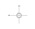
- FIG. 31 is a diagram showing a state in which the character information 3101 displayed in the outer image is controlled to be kept horizontal.
- FIG. 32 is a diagram illustrating a state in which control is performed so as to maintain the position of the inner image or the outer image mapped in the real space.
- FIG. 33 is a flowchart showing an operation example of the head-mounted image display device 1 or 3 according to the content information.
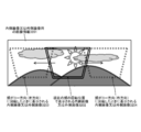
- FIG. 34 is a diagram showing a state in which the display image of the head-mounted image display device 1 or 3 is projected on the wall surface.
- head-mounted image display devices are classified into a light-shielding type (for example, see Patent Document 1) and a light-transmitting type (for example, see Patent Document 2). be able to.
- a light-shielding type for example, see Patent Document 1
- a light-transmitting type for example, see Patent Document 2.
- FIG. 1 shows a state in which a user wearing a light-shielding type head-mounted image display device 1 is viewed from the front.
- the user wears an opaque head-mounted image display device 1 and the left and right eyes are directly covered.
- the side facing the user's face of the head-mounted image display device 1 main body is defined as “inside”, and the opposite side is defined as “outside”.
- An inner display unit (not shown in FIG. 1) that a user observes is disposed at a position facing the left and right eyes inside the apparatus 1 main body.
- an outside display unit that can be observed by an outside person is disposed outside the apparatus main body 1.
- the inner display unit and the outer display unit are configured by a micro display such as an organic EL element or a liquid crystal display.
- FIG. 2 shows a state where the light-shielding type head-mounted image display device 1 is viewed from above.
- the head-mounted image display device 1 has inner display portions for the left eye and the right eye on the inner side, that is, the side surface facing the user's face.
- the inner display unit is configured by a micro display such as an organic EL element or a liquid crystal display.
- the display image of the inner display unit is observed by the user as an enlarged virtual image by passing through the virtual image optical unit.
- the head-mounted image display device 1 is equipped with an eye width adjustment mechanism that adjusts the eye width between the display unit for the right eye and the display unit for the left eye.
- the head-mounted image display device 1 has the outer display unit disposed at a position that is in a front-back relationship with the inner display unit, but the outer display unit is displayed at other locations. Parts may be arranged.
- the head-mounted image display device 1 includes a pair of left and right outer display units, but may include a single or three or more outer display units.
- the head-mounted image display device 1 includes a sound output unit that outputs sound accompanying the image.
- the head-mounted image display device 1 includes a mounting unit (not shown) that mounts the device 1 on the user's head or face. For example, it is fixed to the head by a member such as a belt wound around the back of the head of the wearing user (see, for example, Japanese Patent Application No. 2011-48424 already assigned to the present applicant).
- the head-mounted image display device 1 shown in FIG. 1 and FIG. 2 is a binocular type in which both left and right eyes are provided with a display unit. It is also possible to configure.
- FIG. 3 shows a state in which a user wearing a transparent, see-through type head-mounted image display device 3 is viewed from the front.
- the head-mounted image display device 3 has a structure similar to eyesight correction glasses.
- the side facing the user's face of the head-mounted image display device 3 main body is defined as “inside”, and the opposite side is defined as “outside”.
- a virtual image optical unit including a transparent light guide unit is disposed at a position of the apparatus 3 main body facing the left and right eyes of the user, and an image observed by the user is displayed inside the virtual image optical unit.
- an outside image that can be observed by an outside person is displayed outside the virtual image optical unit.
- the virtual image optical unit is supported by, for example, a spectacle frame-shaped support.
- FIG. 4 shows a state in which the head-mounted image display device 3 is viewed from above.
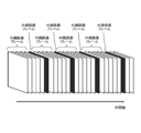
- display panels for displaying and outputting images for the left eye and the right eye are arranged at the left and right ends of the head-mounted image display device 3.
- Each display panel is composed of a micro display such as a liquid crystal display or an organic EL element.
- the display panels multiplex and display the left and right eye inner and outer image frames, for example, by time division.
- the left and right display images are guided to the vicinity of the left and right eyes by the virtual image optical unit and separated into an inner image and an outer image.
- the enlarged virtual image of the inner image is formed on the user's pupil, and the enlarged virtual image of the outer image is formed on a screen disposed outside the virtual image optical unit.
- the details of the configuration in which the virtual image optical unit guides the output image of the display panel to separate the inner image and the outer image and form an enlarged virtual image will be described later.
- the head-mounted image display device 3 has the outer image display area disposed at a position that is in a front-back relationship with the inner image display area. An outside image may be displayed at the place.
- the head-mounted image display device 3 displays the outer image at a pair of left and right locations, but may display the outer image at a single location or at three or more locations.
- the head-mounted image display device 3 includes an audio output unit that outputs audio accompanying the image.
- the head-mounted image display device 3 includes a mounting unit that mounts the device 3 on the user's head or face.
- a temple portion (not shown) rotatably supported at the left and right ends of the main body of the device 3 having a shape similar to a spectacle frame is attached to the head by being hooked on the left and right auricles of the user.
- the head-mounted image display device 3 shown in FIG. 3 and FIG. 4 is a binocular type in which both left and right eyes are provided with a display unit. It is also possible to configure.
- FIG. 5 schematically shows a functional configuration of the light-shielding type head-mounted image display device 1 shown in FIGS. 1 and 2.
- the head-mounted image display device 1 has a function of displaying an inner image seen from the user wearing the device 1 and an outer image seen from the outside of the device.
- each part will be described.
- the control unit 501 includes a ROM (Read Only Memory) 501A and a RAM (Random Access Memory) 501B.
- the ROM 501A stores program codes executed by the control unit 501 and various data.
- the control unit 501 executes the program loaded into the RAM 501B, thereby starting the display control of the inner image seen from the user wearing the device 1 and the outer image seen from the outside, and comprehensively controlling the operation of the device 1 as a whole.
- Examples of data stored in the ROM 501A include device identification information for identifying the device 1 and other device-specific information.
- the input operation unit 502 includes one or more operation elements that the user performs input operations such as keys, buttons, and switches, receives a user instruction via the operation elements, and outputs the instruction to the control unit 501.
- the input operation unit 502 similarly accepts a user instruction including a remote control command received by the remote control reception unit 503 and outputs it to the control unit 501.
- the input operation unit 502 may accept a user instruction through eye movement or blinking movement obtained from a state sensor (described later) such as an electromyographic sensor or an electrooculographic sensor.
- control unit 501 displays an inner image that can be seen from the user wearing the device 1 and an outer image that can be seen from the outside of the device, in response to an instruction from the user via the input operation unit 502.
- Control For example, the control unit 501 displays on / off of the outer image and a display method (display image size, brightness, contrast, hue, display position, continuous display, intermittent display, etc.) in accordance with an instruction from the user.
- Control information Further, the control unit 501 controls the outer image linked or linked with the content to be displayed as the inner image in accordance with an instruction from the user.
- the environment information acquisition unit 504 acquires information about the environment outside the head-mounted image display device 1 and outputs the information to the control unit 501.
- the environment information acquisition unit 504 acquires, for example, environment light intensity, sound intensity, position or location, temperature, weather, time, surrounding image, number of people outside, and the like as environment information.
- the environment information acquisition unit 504 acquires a light amount sensor, a microphone, a GPS (Global Positioning System) sensor, a temperature sensor, a humidity sensor, a clock, an image sensor (camera), and a radiation sensor in order to acquire the environment information.
- Various environmental sensors (all not shown in FIG. 5) may be provided. The environmental information acquired from these environmental sensors is temporarily stored in, for example, the RAM 501B.
- the control unit 501 performs display operations of an inner image that is visible from the user wearing the device 1 and an outer image that is visible from the outside of the device, according to the environment information acquired by the environment information acquisition unit 504. To control. For example, the control unit 501 turns on / off the outer image, the display method (display image size, brightness, contrast, hue, display position, continuous display, intermittent display, etc.) and information to be displayed according to the environment information. To control. Further, the control unit 501 controls the outer image linked or linked to the content to be displayed as the inner image according to the environment information.
- the state information acquisition unit 505 acquires information on the state of the observer wearing the head-mounted image display device 1 and outputs the information to the control unit 501.
- the state information acquisition unit 505 includes, as the state information, for example, the user's work state (whether the user is wearing), the user's action state (the posture of the user's head being worn, movement such as walking, opening / closing state of the heel) ), Mental state (exciting level, arousal level, feelings, emotions, etc., such as whether you are immersed or focused while viewing the inner image) To do.
- the state information acquisition unit 505 acquires the state information from the user by using a wearing sensor such as a mechanical switch, a gyro sensor, an acceleration sensor, a speed sensor, a pressure sensor, a body temperature sensor, a sweat sensor, a muscle sensor
- a wearing sensor such as a mechanical switch, a gyro sensor, an acceleration sensor, a speed sensor, a pressure sensor, a body temperature sensor, a sweat sensor, a muscle sensor
- state sensors (all not shown in FIG. 5) such as an electric sensor, an electrooculogram sensor, and an electroencephalogram sensor may be provided.
- the state information acquired from these state sensors is temporarily stored in, for example, the RAM 501B.
- the control unit 501 includes an inner image that can be seen from the user wearing the device 1 and an outer image that can be seen from the outside of the device according to the current state information of the user acquired by the state information acquisition unit 505. Control the display behavior of. For example, the control unit 501 displays on / off of the outer image and a display method (display image size, brightness, contrast, hue, display position, continuous display, intermittent display, etc.) according to the user status information. Controls information (display of icons and character information expressing the degree of eye opening and line of sight). Further, the control unit 501 controls the outer image linked or linked to the content to be displayed as the inner image according to the user status information.
- the communication unit 506 performs communication processing with other devices, modulation / demodulation of communication signals, and encoding / decoding processing.
- the communication unit 506 receives an image signal to be displayed and output as an inner image from an external device (not shown) serving as an image source.
- the communication unit 506 can also receive an outer image different from the inner image from the external device.
- the inner image or the outer image received by the communication unit 506 and demodulated and decoded, or other received data is supplied to the control unit 501.
- the control unit 501 sends transmission data to the external device from the communication unit 506.
- the configuration of the communication unit 506 is arbitrary.
- the communication unit 506 can be configured according to a communication standard used for transmission / reception operations with an external device serving as a communication partner.
- the communication standard may be either wired or wireless.
- Communication standards such as MHL (Mobile High-definition Link), USB (Universal Serial Bus), HDMI (registered trademark) (Multidefinition Multimedia Interface), Bluetooth (registered trademark) communication, and other infrared communication can be used. .
- the content information acquisition unit 507 acquires image content information input via the communication unit 506.
- the content information acquisition unit 507 is realized by a program executed in the control unit 501, but the content information acquisition unit 507 can be configured as dedicated hardware outside the control unit 501.
- the content information acquisition unit 507 for example, metadata (content title, genre, detailed information, URL of related site (Uniform Resource Locator), etc.) associated with the image content, the total playback time of the image content, and the current playback position Alternatively, content information such as remaining playback time, parental control, and other usage restrictions is acquired.
- the content information acquisition unit 507 includes a decoder that decodes data such as a character string that is encoded and embedded in the image content body.
- the control unit 501 performs display operations of an inner image that can be seen from the user wearing the device 1 and an outer image that can be seen from the outside of the device, according to the content information acquired by the content information acquisition unit 507.
- the control unit 501 turns on / off the outer image, the display method (display image size, brightness, contrast, hue, display position, continuous display, intermittent display, etc.), and information to be displayed (content display).
- a character string such as a URL that provides detailed information of content and related information, or a QR code (registered trademark) obtained by encoding the character string is controlled.
- the control unit 501 controls the outer image linked or linked to the content to be displayed as the inner image according to the content information.
- the image processing unit 508 includes an inner image generation unit 508-1 that generates an inner image based on the image signal output from the control unit 501, and an outer image that generates an outer image based on the image signal output from the control unit 501.
- An image generation unit 508-2 is included to further perform signal processing such as image quality correction on the generated inner image and outer image, and to match the screens of the inner image display panel 511 and the outer image display panel 512, respectively. Convert to resolution. However, when the same image as the inner image is displayed outside, the outer image generation unit 508-2 is omitted.
- the display drive units 509 and 510 sequentially select the pixels of the inner image display panel 511 and the outer image display panel 512 for each row, perform line sequential scanning, and pixel signals based on the image signals that have undergone signal processing. Supply.
- the inner image display panel 511 and the outer image display panel 512 are constituted by, for example, a micro display such as an organic EL element or a liquid crystal display (the inner image display panel 511 and the outer image display panel 512 are made of the same material. Not necessary).
- the inner image display panel 511 is disposed inside the head-mounted image display device 1 (that is, on the side surface of the main body of the device 1 facing the user's face).
- a virtual image optical unit 513 is disposed in front of the display surface of the inner image display panel 511.
- the virtual image optical unit 513 enlarges and projects the display image of the inner image display panel 511 and is observed as an enlarged virtual image by the user.
- the outer image display panel 512 is disposed on the outer side of the head-mounted image display device 1 (that is, on the side surface of the main body of the device 1 opposite to the inner side).
- a projection optical unit 514 may be disposed in front of the display surface of the outer image display panel 512.
- the projection optical unit 514 enlarges and projects the real image of the outer image displayed on the outer image display panel 512 onto a wall surface (not shown) in the vicinity of the head-mounted image display device 1. That is, the head-mounted image display device 1 can be used as a small projector.
- FIG. 34 shows a state in which the display image of the head-mounted image display device 1 is projected onto the wall surface (provided that the inner image and the outer image are the same).
- FIG. 5 only one inner image display panel 511 and virtual image optical unit 513 are drawn for the sake of simplification. However, when the head-mounted image display device 1 is a binocular type, FIG. An inner image display panel 511 and a virtual image optical unit 513 are provided for each of the left and right eyes.
- FIG. 6 schematically shows a functional configuration of the head-mounted image display device 3 of the transmissive type shown in FIGS. 3 and 4.
- the head-mounted image display device 3 has a function of displaying an inner image seen from the user side wearing the device 3 and an outer image seen from the outside of the device.
- the same reference numerals are assigned to the same functional elements as those of the head-mounted image display device 1 shown in FIG. In the following, functional elements different from the head-mounted image display device 1 will be mainly described.
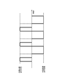
- the image multiplexing unit 609 multiplexes the inner image and outer image frames generated by the inner image generation unit 508-1 and the outer image generation unit 508-2, respectively, so as to be displayed and output on a single display panel 611.
- the multiplexing method is arbitrary, the following description will be made assuming that time division multiplexing is performed.
- the image multiplexing unit 609 inserts one outer image frame for every N inner image frames continuous on the time axis.
- the luminance ratio between the inner image and the outer image is simply N: 1 (assuming that the luminance when the inner image and the outer image are output is the same).
- N 4 in the illustrated example.
- the outer image finally displayed and output becomes a brighter and clearer image.
- the multiplexing process in the image multiplexing unit 609 is omitted.
- the transmissive or see-through type head-mounted image display device 3 receives, as an image display system, a display panel 611 that multiplexes and displays an inner image and an outer image, and display light displayed on the display panel 611. Then, it is separated into an inner image and an outer image, and a virtual image / real image optical unit 612 that guides an enlarged virtual image of the inner image to the observer's pupil and guides a real image of the outer image to the outside is provided.
- the display panel 611 includes a micro display such as an organic EL (Electro Luminescence) display, an inorganic EL display, and a liquid crystal display (LCD).
- a micro display such as an organic EL (Electro Luminescence) display, an inorganic EL display, and a liquid crystal display (LCD).
- the following description is based on the assumption that a liquid crystal display that outputs image light composed of linearly polarized light is applied to the display panel 611.
- the display driver 610 sequentially selects pixels of the display panel 611 for each row, performs line sequential scanning, and supplies a pixel signal based on the image signal subjected to signal processing.
- the virtual image / real image optical unit 612 separates the multiplexed inner image and outer image by, for example, optical action, forms a virtual image obtained by enlarging the inner image on the pupil of the user, and arranges the real image of the outer image outside.
- the image is formed on the screen (see FIG. 4).
- a projection optical unit 514 may be further disposed in front of the screen on which the real image of the outer image is projected.
- the projection optical unit 514 enlarges and projects the real image of the outer image displayed on the outer image display panel 512 onto a wall surface (not shown) in the vicinity of the head-mounted image display device 1 (same as above). That is, the head-mounted image display device 3 can be used as a small projector (see FIG. 34).
- FIG. 8 shows a configuration example of the virtual image / real image optical unit 612.
- the illustrated virtual image / real image optical unit 612 is arranged inside a collimating optical unit 801, a half wave plate (HWP) 802, a light guide unit 803, and a light guide unit 803.
- the screen 807 for projecting is provided.
- the polarization beam splitter 804 is disposed with an inclination of 45 degrees with respect to the optical axis of the incident light from the display panel 611.
- the quarter-wave plate 805 is disposed so as to be orthogonal to the optical axis of the incident light from the display panel 611.
- the concave mirror 806 is formed on the end surface of the light guide 803 that is opposite to the display light incident side from the display panel 611.
- the collimating optical unit 801 is composed of, for example, a convex lens, and is an optical system that allows a light beam emitted from each pixel of the display panel 611 to enter into a parallel light beam group. Be placed.
- the parallel light flux groups emitted from the collimating optical unit 801 are incident on the light guide unit 803 via the half-wave plates 802, respectively.
- the display light immediately after being emitted from the display panel 611 is composed of only the S-polarized component (see FIG. 9).
- a half-wave plate 802 is disposed between the display panel 611 and the polarization beam splitter 804.
- the display light emitted from the display panel 611 is incident on the half-wave plate 802 after becoming a parallel light flux group in the collimating optical unit 801.
- the half-wave plate 802 used here can dynamically polarize its optical axis direction.
- An example of a half-wave plate 802 that can dynamically polarize the optical axis direction is an optical doubler composed of ferroelectric liquid crystal (see, for example, Patent Document 5).
- the optical axis direction of the half-wave plate 802 when the optical axis direction of the half-wave plate 802 is set to 0 degree, the display light composed of S-polarized light passes through the half-wave plate 802 as it is (see FIG. 10). Further, when the optical axis direction of the half-wave plate 802 is inclined by 45 degrees, the display light converted into P-polarized light passes from the half-wave plate 802 (see FIG. 11). Therefore, by changing the angle of the optical axis of the half-wave plate 802, the polarization of the display light passing through the half-wave plate 802 can be switched alternately between S-polarized light and P-polarized light. Further, the duty of the S-polarized light and the P-polarized light passing through the half-wave plate 802 can be arbitrarily adjusted by switching the angle setting period of the optical axis of the half-wave plate 802.
- the light guide 803 is made of a substantially transparent material.
- the parallel light flux group composed of S-polarized light or P-polarized light after passing through the half-wave plate 802 is incident from one end face of the light guide unit 803, it is totally reflected inside the light guide unit 803 and travels straight. Propagate to.
- the polarization beam splitter 804 is disposed on the optical path of the parallel light flux group so as to be inclined by 45 degrees with respect to the optical axis of the incident light from the display panel 611.
- the polarization beam splitter 804 has a property of transmitting P-polarized light and reflecting S-polarized light (well known). As described above, the parallel light flux group is alternately switched between the S-polarized light and the P-polarized light by changing the angle of the optical axis of the half-wave plate 802.
- the optical axis direction of the half-wave plate 802 When the optical axis direction of the half-wave plate 802 is set to 0 degree and the passing light becomes S-polarized light, it is reflected on the front side of the polarizing beam splitter 804 (reflected light A in FIG. 8).
- the reflected light A is emitted from the inner side surface of the light guide unit 803 and then observed by the observer's pupil as an enlarged virtual image of the display image on the display panel 611. Therefore, the optical axis direction of the half-wave plate 802 may be set to 0 degrees at the timing of displaying the inner image on the display panel 611.
- the optical axis direction of the half-wave plate 802 is inclined by 45 degrees and the passing light is P-polarized light, it passes through the polarization beam splitter 804.
- This transmitted light is once converted into circularly polarized light by the rear quarter-wave plate 805 (see FIG. 12).
- the circularly polarized light is reflected and collected by the concave mirror 806 formed on the other end face of the light guide unit 803, and then passes through the quarter-wave plate 805 again to be converted to S-polarized light (see FIG. 13).
- this S-polarized light is reflected on the back side of the polarizing beam splitter 804 (reflected light B in FIG. 8), it proceeds to the opposite side, that is, to the outside of the observer's pupil.
- a screen 807 made of a scatterer is disposed on the opposite side of the observer's pupil, that is, outside.
- the S-polarized light B reflected from the back side of the polarization beam splitter 804 is emitted from the outer side surface of the light guide unit 803 and then projected onto the screen 807 to project and display a real image of the display image on the display panel 611.
- the timing of displaying the outer image on the display panel 611 may be set so that the optical axis direction of the half-wave plate 802 is inclined by 45 degrees.
- the reflectance of the polarization beam splitter 804 is increased, and preferably the reflectance is 90% or more.
- the size of the screen 807 is not so large and is preferably 2 inches or less.
- the gain of the screen 807 is increased, and is preferably 2 or more (the gain at the time of complete diffusion is 1, and the diffusion characteristic is such that the front luminance is twice or more compared to the gain 1).
- a polymer dispersed liquid crystal (Polymer Dispersed Liquid Crystal: PDLC) can be used.
- the PDLC can scatter light by inducing an irregular state of liquid crystal molecules by the action of a polymer network according to an applied voltage. Therefore, only when the outside image is displayed on the display panel 611 and the display light is converted to P-polarized light by the half-wave plate 802 and the real image is projected and displayed, the scattering action of the screen 807 can be caused. That's fine.
- the transparency of the head-mounted image display device 3 that is, the see-through characteristics can be utilized.
- a hologram screen can be used as the screen 807.
- the hologram screen is composed of a structure in which interference fringes are laminated on a resin film, and has a property of diffracting light of a specific wavelength and being transparent to light of other wavelengths. Therefore, only when the outside image is displayed on the display panel 611 and the display light is converted into P-polarized light by the half-wave plate 802 and the real image is projected and displayed, the display image on the display panel 611 is displayed at a specific wavelength. Output.
- the display panel 611 is displayed.
- the display image is displayed at a wavelength other than the specific wavelength, the transparency of the screen 807 can be maintained and the transparency of the head-mounted image display device 3, that is, the see-through characteristic can be utilized.
- a projection optical unit 514 may be further disposed in front of the screen 807.
- the projection optical unit 514 enlarges and projects the real image of the outer image displayed on the display panel 611 onto a wall surface in the vicinity of the head-mounted image display device 3 (see FIG. 34). That is, the head-mounted image display device 3 can also be used as a small projector (described above).
- the optical axis direction of the half-wave plate 802 when the optical axis direction of the half-wave plate 802 is set to 0 degrees, an enlarged virtual image of the display image on the display panel 611 is observed by the observer.
- the optical axis direction of the half-wave plate 802 when the optical axis direction of the half-wave plate 802 is inclined by 45 degrees, a real image of the display image on the display panel 611 is projected on the screen 807. Therefore, in synchronization with the change in the angle of the optical axis of the half-wave plate 802, the inner image and the outer image are alternately switched on the display panel 611 so that the inner image is an enlarged virtual image on the observer's pupil.
- the outside image can be output as a real image on the screen 807.
- the inner image is displayed on the display panel 611 in synchronization with the period in which the optical axis direction of the half-wave plate 802 is set to 0 degrees, and the optical axis direction of the half-wave plate 802 is set to 45 degrees.
- the outer image may be displayed on the display panel 611 in synchronism with the tilting period.
- FIG. 14 shows an operation example of the optical axis orientation of the half-wave plate 802.
- a section in which the optical axis direction of the half-wave plate 802 is set to 0 degrees and a section in which the half-wave plate 802 is set to 45 degrees are alternately switched.
- the S-polarized light emitted from the display panel 611 is incident on the polarization beam splitter 802, and an enlarged virtual image of the display image on the display panel 611 is observed by the observer.
- the virtual image display section observed in Therefore, the inner image may be displayed on the display panel 611 in synchronization with the virtual image display section.
- the P-polarized light emitted from the display panel 611 is incident on the polarization beam splitter 802, and the real image of the display image on the display panel 611 is applied to the screen 807.
- the projected real image display section. Therefore, the outer image may be displayed on the display panel 611 in synchronization with the real image display section.
- the display panel 611 should display the inner image within the virtual image display section in which the optical axis direction of the half-wave plate 802 is set to 0 degrees, but it is not necessary to light the image over the entire section.
- FIG. 15 shows a display operation example of the display panel 611 synchronized with the operation of the optical axis direction of the half-wave plate 802.
- the display panel 611 lights up the virtual image, that is, the inner image only in a part of the virtual image display section.
- the brightness of the magnified virtual image observed by the observer can be adjusted by the ratio of the lighting time of the image in the virtual image display section.
- the outer image is a projected image projected on the screen 807, and since the luminance is relatively low, it is considered that the display unit 611 preferably lights up the image over the entire real image display section.
- the inner image or the outer image is alternately time-divisionally switched by switching the optical axis direction of the half-wave plate 802 in two stages of 0 degree and 45 degrees.
- the example to be displayed on has been described.
- the optical axis direction of the half-wave plate 802 by setting the optical axis direction of the half-wave plate 802 to an angle ⁇ between 0 ° and 45 ° (see FIG. 16), the S-polarized component and the P-polarized component of the emitted light.
- the ratio of can be adjusted.
- the half-wave plate 802 itself may be physically rotated.
- the display panel 611 Is observed as an enlarged virtual image of the display image.
- the P-polarized light component after passing through the half-wave plate 802 (see FIG. 18) is transmitted through the polarization beam splitter 804 and once converted into circularly polarized light by the rear quarter-wave plate 805. After being converted (see FIG. 19), after being reflected by the concave mirror 806 and again passing through the quarter wave plate 805, it is converted to S-polarized light (see FIG. 20), and then the polarized beam Since it is reflected on the back side of the splitter 804 (reflected light B in FIG. 8), it is projected on the screen 807 as an outer image.
- the ratio of the S-polarized component and the P-polarized component in other words, the luminance ratio between the inner image and the outer image is cos 2 ⁇ : sin 2 ⁇ .
- the luminance of the outer image can be adjusted by changing the optical axis direction ⁇ of the half-wave plate 802.
- the multiplexed inner image and outer image are separated, so that an outer image different from the inner image can be presented.
- the configuration of the virtual image / real image optical unit 612 can be simplified.
- FIG. 21 shows another configuration example of the virtual image / real image optical unit 612.
- the illustrated virtual image / real image optical unit 612 connects the inner image with the light guide unit 2101, the half mirror 2102 disposed inside the light guide unit, and the concave mirror 2103 formed on the end surface of the light guide unit 2101.
- a collimating optical unit 2104 for imaging and a screen 2105 for projecting an outside image are provided.
- Display light emitted from the display panel 611 is incident from one end face of the light guide unit 2101.
- the half mirror 2102 is arranged to be inclined by 45 degrees with respect to the optical axis of the incident light from the display panel 611, and reflects a part of the incident display light and transmits a part thereof.
- the reflected light and the transmitted light have substantially the same intensity, for example, the intensity of the reflected light may be adjusted to be larger.
- the display light reflected on the front side of the half mirror 2102 (reflected light A in FIG. 21) is emitted from the inner side surface of the light guide unit 2101 and then collected by the collimating optical unit 2104 and displayed on the display panel 611. It is observed as an enlarged virtual image of the observer's pupil.
- the light that has passed through the half mirror 2102 is reflected and collected by the concave mirror 2103 formed on the other end face of the light guide unit 2101 and then reflected by the back side of the half mirror 2102 (in FIG. 21).
- Reflected light B The reflected light B is emitted from the outer side surface of the light guide unit 2101 and then projected onto the screen 2105 to project and display a real image of the display image on the display panel 611.
- the reflectance of the half mirror 2102 is increased, and preferably the reflectance is 90% or more.
- the size of the screen 2105 is not so large, and is preferably 2 inches or less.
- the gain of the screen 2105 is increased, and is preferably 2 or more (the gain at the time of complete diffusion is 1, and the diffusion characteristic is such that the front luminance is twice or more compared to the gain 1).
- FIG. 22 shows still another configuration example of the virtual image / real image optical unit 612.
- the illustrated virtual image / real image optical unit 612 includes a light guide unit 2201, a half mirror 2202 disposed inside the light guide unit 2201, a plane mirror 2203 formed on the end surface of the light guide unit 2201, and an inner image.
- a collimating optical unit 2204 for forming an image, a projection optical unit 2205 for projecting an outside image, and a screen 2206 are provided.
- Display light emitted from the display panel 611 is incident from one end face of the light guide unit 2201.
- the half mirror 2202 is arranged to be inclined by 45 degrees with respect to the optical axis of the incident light from the display panel 611, and reflects a part of the incident display light and transmits a part (the same as above).
- the reflected light and the transmitted light have substantially the same intensity, for example, the intensity of the reflected light may be adjusted to be larger.
- the display light reflected on the front side of the half mirror 2202 (reflected light A in FIG. 22) is emitted from the inner side surface of the light guide unit 2201, and then collected by the collimating optical unit 2204, and is displayed on the display panel 611. It is observed as an enlarged virtual image of the observer's pupil.
- the light that has passed through the half mirror 2202 is totally reflected by the plane mirror 2203 formed on the other end face of the light guide unit 2201, and then reflected by the back side of the half mirror 2202, so that the light of the light guide unit 2201.
- the light is emitted from the outer side surface (reflected light B in FIG. 22).
- the reflected light B is enlarged and projected on the screen 2206 by the projection optical unit 2205 to display a projected image of the display image.
- the reflectance of the half mirror 2202 is increased, and the size of the screen 2206 is not increased so much, and the gain of the screen 2206 is increased. Is preferred (same as above).
- the head-mounted image display device can be said to be one of the ultimate displays of an individual.
- the conventional head-mounted image display device does not include a means for transmitting information to the outside, the surrounding persons cannot receive any information from the wearing user. Also, the user himself / herself cannot transmit information to the outside unless the device is once removed and content viewing is interrupted.
- the head-mounted image display devices 1 and 3 also have a function of displaying an outer image visible from the outside of the device in addition to the inner image visible from the user wearing the device. ing. Accordingly, the surrounding person can know the state of the user himself / herself, what he / she is doing, what he / she is watching, and the degree of concentration or immersion in viewing through the outer image. In addition, the user himself / herself can transmit information regarding his / her state and the content being viewed through the outer image even when the apparatus is worn (that is, while viewing the content is continued).
- control unit 501 switches on / off of the outer image and the display method (the size of the display image, the brightness, and the like) in accordance with an instruction from the user via the input operation unit 502. (Contrast, hue, display position, continuous display or intermittent display, etc.) and the information to be displayed. Further, the control unit 501 controls the outer image linked or linked with the content to be displayed as the inner image in accordance with an instruction from the user.
- An example of a display control method for the outer image and the inner video in accordance with an instruction from the user is summarized in Table 1 below.
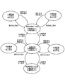
- FIG. 23 illustrates an operation example of the head-mounted image display device 1 or 3 according to an instruction from the user via the input operation unit 502 in the form of a state transition diagram.
- the head-mounted image display device 1 or 3 is set to the inner image on and the outer image off.
- the outside image is turned on and the both-side image on state is entered.
- the display of the outer image is instructed to be off in the both-side image on state, the outer image is turned off and the initial state is restored.
- both-side image ON state in accordance with an instruction from the user via the input operation unit 502, switching control of images to be displayed as the outer image and the inner image, color adjustment of the outer image and the inner image, the outer image, and the inner image Brightness control, switching of the display size of the outside image, movement of the display area of the outside image, etc. (full display, display on either the left or right side, display using a part of the screen, etc.)
- the inner image In the initial state, when the display of the inner image is instructed through the input operation unit 502, the inner image is turned off and the both-side image off state is entered. Further, when the display of the inner image is instructed in the both-side image off state, the inner image is turned on and the initial state is restored.
- the same image as the inner image or a dedicated outer image different from the inner image is displayed as the outer image (for example, when the user is currently viewing
- the replaced image content is displayed as the outside image.
- information on the surrounding environment acquired by the environment sensor (described above), the user status acquired by the state sensor (described above), and the like can be displayed as the outside image.
- information to be displayed as an outer image in accordance with an instruction from the user via the input operation unit 502 (including blink operation and eye movement detected by an electromyographic sensor or an electrooculographic sensor) (for example, a slide show) As well as).
- the outer image may be displayed on the inner side so that the user who is wearing the device can visually confirm the outer image.
- the control unit 501 may cause one of continuous display, intermittent display, and timer display to be performed in response to an instruction from the user via the input operation unit 502.
- the image control control unit 501 according to the surrounding environment, according to the environment information acquired by the environment information acquisition unit 504, an inner image that can be seen from the user wearing the device 1 or 3, and an outer image that can be seen from the outside of the device Control the display behavior of.
- An example of the display control method of the outer image and the inner video according to the environmental information is summarized in Table 2 below.
- FIG. 24 illustrates an operation example of the head-mounted image display device 1 or 3 according to the environment information in the form of a flowchart.
- the illustrated processing operation is started periodically, for example.
- the environmental information acquisition unit 504 acquires output information of various environmental sensors (described above) as environmental information (step S2401). Then, the control unit 501 analyzes the acquired environment information (step S2402), identifies the surrounding environment, and checks whether an environment change in which switching between the inner image and the outer image has occurred (step S2403). ).
- control part 501 controls the display of the outer image according to the present environment (step S2404).
- control unit 501 adjusts the brightness level of the outer image so as to suit the current surrounding environment by determining that it is during the day or after sunset according to the current time measured by the clock.
- control unit 501 may perform intermittent display of the outer image and timer display according to the current time measured by the clock.
- control unit 501 determines whether there is a person around the head-mounted image display device 1 or 3 based on the recognition result of the captured image of the surrounding camera, and in response to the appearance of the person, Start displaying the outside image. Further, the control unit 501 controls the display area and display size of the outer image according to the place (orientation) and distance where the person who has appeared is present. In addition, the control unit 501 controls the display area and display size of the outer image according to the number of people around. Since it is assumed that when the number of people is large, the confidential level of the image is lowered, the control unit 501 may control the luminance level of the external image according to the number of people around.
- the image control control unit 501 according to the user state, the inner image that can be seen from the user side wearing the device 1 or 3, the device 1 or 3, according to the current state information of the user acquired by the state information acquisition unit 505. 3 controls the display operation of the outside image visible from the outside.
- An example of a display control method for the outer image and the inner video according to the state information is summarized in Table 3 below.
- FIG. 25 illustrates an example of the operation of the head-mounted image display device 1 or 3 according to the user status information in the form of a flowchart.
- the illustrated processing operation is started periodically, for example.
- the state information acquisition unit 505 acquires output information of various state sensors (described above) as state information (step S2501). And the control part 501 analyzes the acquired state information (step S2502), specifies a user's present working state, action state, mental state, and physiological state, and the user state that should be notified to surrounding persons Is checked (step S2503).
- control unit 501 controls the display of the outer image according to the user state (step S2504).
- control unit 501 specifies the state of the eyelid or the direction of the line of sight based on output information from state sensors such as an electromyographic sensor, an electrooculogram sensor, or a camera, the state where the eyelid is closed (the degree of opening of the eyes)
- state sensors such as an electromyographic sensor, an electrooculogram sensor, or a camera
- an icon for example, see FIGS. 26 and 27
- icons as shown in FIG. 26 and FIG. 27 may be displayed superimposed on the outer image that is the same as the inner image.
- control unit 501 identifies the mental state of the user (exciting degree such as whether the inner image is immersed or concentrated while observing the inner image, arousal degree, emotion or emotion) based on the output information of the state sensor, An icon (not shown) representing the mental state is displayed on the outer image. Furthermore, based on the mental state, it is determined whether the user may speak to the user, or the viewing of the inner image may be interrupted or disturbed, and an icon (not shown) that represents the determined situation. Alternatively, a message sentence such as “Immerse Now” or “Don't Speak!” Is displayed on the outer image.
- blink movement can be detected based on output information from state sensors such as myoelectric sensors and electrooculogram sensors.
- the control unit 501 can determine the mental state of the user according to the number of blinks per hour and the blink time.
- FIG. 28 illustrates a method for determining the number of blinks per hour detected by the electrooculography and the mental state (wakefulness / drowsiness / concentration) of the user according to the blink time.
- control unit 501 can determine the mental state of the user according to the blink interval and the blink time.
- FIG. 29 illustrates a determination method of the user's mental state (wakefulness / drowsiness / concentration) according to the blink interval and blink time detected by the electrooculographic method.
- the blink time detected by the electrooculogram is tb and the blink interval is ti.
- the blink time threshold is Thb
- the blink interval threshold is Thi
- the blink interval maximum threshold is Mi
- the average blink time A (tb) and the average blink interval A (ti) are each set at a sampling number n. Calculation is performed as in the following formulas (1) and (2).
- the state is estimated in the following detection priority order.
- FIG. 30 illustrates a determination method of the user's mental state (wakefulness / drowsiness / concentration) according to the blink interval and blink time detected by the photographing method.
- the state is estimated in the following order of detection priority based on the average blink time A (tb) and the average blink interval A (ti) calculated according to the above equations (1) and (2). .
- the electroencephalogram when the eye is closed can be acquired from the electrooculogram electrode.
- An alpha wave component (frequency about 10 Hz, amplitude of several tens of ⁇ V) can be observed from the brain wave when the eyes are closed, but the alpha wave disappears from the brain wave during sleep.
- control unit 501 when the control unit 501 specifies the user's behavior state based on the output information of the state sensor, the control unit 501 displays the outer image and the inner image so as to match the behavior state.
- the posture of the user's head (or the head-mounted image display device 1 or 3 worn by the user) can be detected based on output information from a state sensor such as a gyro sensor, an acceleration sensor, or a camera. .
- a state sensor such as a gyro sensor, an acceleration sensor, or a camera.
- control unit 501 When it is detected that the head is tilted sideways (roll direction), the control unit 501 performs control so that the character information 3101 displayed in the outer image is kept horizontal (see FIG. 31).
- the control unit 501 keeps the position of the inner image or the outer image mapped in the real space. For example, it is assumed that an image indicated by reference number 3201 in FIG. 32 is prepared for displaying an inner image or an outer image, and an area indicated by reference number 3202 is displayed at the current head rotation position. In such a case, when the head rotates in the yaw direction (leftward), the head moves to the display area indicated by reference numeral 3203. When the head rotates in the yaw direction (rightward), the head moves to the display area indicated by reference numeral 3204.
- the user can determine behavioral states such as rest (including standing, sitting, and standing), walking, running, and moving on a moving object. Can be detected.
- the control unit 501 performs control so that the display of the outer image is adapted to such a behavior state.
- the image control control unit 501 corresponding to the display content includes an inner image that can be seen from the user wearing the device 1 or 3 and an outer image that can be seen from the outside of the device, according to information on the content displayed as the inner image. Control display behavior.
- An example of a display control method for the outer image and the inner video according to the content information is summarized in Table 5 below.
- FIG. 33 illustrates an example of the operation of the head-mounted image display device 1 or 3 according to the content information in the form of a flowchart.
- the illustrated processing operation is started periodically, for example.
- step S3302 when the content information acquisition unit 507 acquires content information (step S3301), the control unit 501 analyzes the acquired state information (step S3302).
- the content information acquisition unit 507 for example, metadata (content title, genre, detailed information, URL of related site (Uniform Resource Locator), etc.) associated with the image content, the total playback time of the image content, and the current playback position Alternatively, content information such as remaining playback time, parental control, and other usage restrictions is acquired.
- metadata content title, genre, detailed information, URL of related site (Uniform Resource Locator), etc.
- URL of related site Uniform Resource Locator
- control unit 501 checks whether or not content information to be notified to surrounding persons has been acquired (step S3103).
- step S3303 when the content information to be notified to the surrounding persons can be acquired (Yes in step S3303), the control unit 501 is the user wearing the apparatus 1 according to the content information acquired by the content information acquisition unit 507. The display operation of the inner image seen from the side and the outer image seen from the outside of the device is controlled (step S3304).
- control unit 501 turns on / off the outer image, the display method (display image size, brightness, contrast, hue, display position, continuous display, intermittent display, etc.), and information to be displayed (content display).
- a character string such as a URL that provides detailed information of content and related information, or a QR code (registered trademark) obtained by encoding these character strings is controlled.
- control unit 501 controls the outer image linked or linked to the content to be displayed as the inner image according to the content information.
- An image display device used by being mounted on a user's head or face the first display unit displaying an inner image visible from the user side, and an outer image visible from the outside of the image display device
- An image display device comprising: (2) The display unit is disposed in a place visible from the user side and displays the inner image, and is disposed in a place visible from the outside of the image display device and displays the outer image.
- the image display device according to (1) including a second display device.
- the display unit guides the inner image displayed on the display device to a place visible from the user side and displays the inner image displayed on the display device while displaying the inner image and the outer image.
- the image display device further including a light guide unit that guides the formed outside image to a place that can be seen from the outside of the image display device.
- the image display device further including a projection unit that projects the outer image toward the outside of the image display device.
- the apparatus further including an input operation unit in which the user performs an input operation, wherein the control unit controls display of the inner image and the outer image according to the input operation by the user.
- Image display device (6)
- the control unit turns on / off the display of the inner image or the outer image, adjusts the color of the inner image or the outer image, the inner image or the outer image according to an input operation on the input operation unit by the user.
- the image display device wherein brightness adjustment of the outer image, display size switching of the outer image, or display area movement of the outer image is performed.
- the control unit in response to an input operation performed on the input operation unit by the user, the control unit, as the outer image, is the same image as the inner image, an image different from the inner image, information on the surrounding environment, the user's information.
- the control unit switches display of the outer image in accordance with an input operation based on the user's blink operation or eyeball movement.
- the image display device (9) The image display device according to (5), wherein the control unit displays the outer image as the inner image in response to an input operation performed on the input operation unit by the user. (10) The image according to (5), wherein the control unit prohibits or cancels the operation on the outer image or the inner image in accordance with an input operation on the input operation unit by the user. Display device. (11) In the above (5), the control unit causes the external image to be continuously displayed, intermittently displayed, or displayed at predetermined time intervals in accordance with an input operation to the input operation unit by the user. The image display device described. (12) The image processing apparatus further includes an environment information acquisition unit that acquires information related to the surrounding environment of the image display device, and the control unit controls display of the inner image and the outer image based on the surrounding environment.
- the image display device according to 1).
- the control unit controls the luminance of the outer image in response to detecting a change in brightness of ambient light.
- the control unit controls intermittent display or timer display of the outer image in response to elapse of a current time.
- the control unit controls display on / off, a luminance level, a display area, and a display size of the outer image according to the number of people around.
- the apparatus further including a state information acquisition unit that acquires information related to the state of the user, wherein the control unit controls display of the inner image and the outer image based on the state of the user.
- the image display device according to (16), wherein the control unit performs control so as to maintain a position of the inner image or the outer image according to rotation of the user's head.
- a content information acquisition unit that acquires content information related to image content to be displayed on the inner display unit, and the control unit controls display of the outer image according to the content information.
- Image display device (23) An image display method used by being mounted on a user's head or face, the first display step displaying an inner image visible from the user side, and an outer image visible from the outside of the image display device An image display method comprising: a second display step for displaying the image; and a control step for controlling display of the inner image and the outer image.
- a computer-readable recording medium storing a computer program for controlling an image display device used by being mounted on a user's head or face, wherein the computer program stores the computer as the user
- a first display unit that displays an inner image visible from the side
- a second display unit that displays an outer image viewed from the outside of the image display device
- a control unit that controls display of the inner image and the outer image.
- Head-mounted image display devices can be classified into a light-shielding type and a light-transmissive type, but the technology disclosed in this specification can be applied to any of these types. Further, the head-mounted image display device can be classified into a binocular type having a display unit in both the left and right eyes, and a monocular type having a display unit in only one of the left and right. The technology disclosed in this document can be applied to any of these types. Of course, the head-mounted image display device may be a glasses-type or an ear-hook type.
- Head-mounted image display device (light-shielding type) 3... Head-mounted image display device (transmissible type) 501 ... Control unit, 501A ... ROM, 501B ... RAM 502 ... Input operation unit, 503 ... Remote control receiving unit 504 ... Environment information acquisition unit, 505 ... Status information acquisition unit 506 ... Communication unit, 507 ... Content information acquisition unit 508 ... Image processing unit 508-1 ... Inner image generation unit, 508 -2 ... outside image generation unit 509, 510 ... display drive unit 511, 512 ... display panel 513 ... virtual image optical unit, 514 ... projection optical unit 609 ... image multiplexing unit, 610 ... display drive unit 611 ... display panel, 612 ...
- Virtual image / real image optical unit 801 ... collimating optical unit, 802 ... half-wave plate 803 ... light guide unit, 804 ... polarization beam splitter 805 ... quarter-wave plate, 806 ... concave mirror 807 ... screen 2101 ... light guide Part 2102 ... half mirror 2103 ... concave mirror, 2104 ... collimating optical part 2105 ... screen 2201 ... light guide part, 202 ... half-mirror 2203 ... concave mirror, 2204 ... collimated optical section 2205 ... the projection optical unit, 2206 ... screen
Landscapes
- Engineering & Computer Science (AREA)
- Physics & Mathematics (AREA)
- Theoretical Computer Science (AREA)
- General Physics & Mathematics (AREA)
- General Engineering & Computer Science (AREA)
- Multimedia (AREA)
- Signal Processing (AREA)
- Human Computer Interaction (AREA)
- Optics & Photonics (AREA)
- Biomedical Technology (AREA)
- Health & Medical Sciences (AREA)
- Dermatology (AREA)
- General Health & Medical Sciences (AREA)
- Neurology (AREA)
- Neurosurgery (AREA)
- Computer Hardware Design (AREA)
- Controls And Circuits For Display Device (AREA)
- Transforming Electric Information Into Light Information (AREA)
- Testing, Inspecting, Measuring Of Stereoscopic Televisions And Televisions (AREA)
- User Interface Of Digital Computer (AREA)
Abstract
Description
前記ユーザー側から見える内側画像を表示する第1の表示部と、
前記画像表示装置の外部から見える外側画像を表示する第2の表示部と、
前記内側画像と前記外側画像の表示を制御する制御部と、
を具備する画像表示装置置である。 The present application has been made in consideration of the above-described problems, and the technology according to claim 1 is an image display device used by being mounted on a user's head or face,
A first display unit for displaying an inner image visible from the user side;
A second display unit that displays an outer image that is visible from the outside of the image display device;
A control unit for controlling display of the inner image and the outer image;
Is an image display device.
前記ユーザー側から見える内側画像を表示する第1の表示ステップと、
前記画像表示装置の外部から見える外側画像を表示する第2の表示ステップと、
前記内側画像と前記外側画像の表示を制御する制御ステップと、
を有する画像表示方法である。 Further, the technology according to claim 19 of the present application is an image display method used by being worn on a user's head or face,
A first display step of displaying an inner image visible from the user side;
A second display step of displaying an outer image visible from the outside of the image display device;
A control step for controlling display of the inner image and the outer image;
Is an image display method.
前記ユーザー側から見える内側画像を表示させる第1の表示部、
前記画像表示装置の外部から見える外側画像を表示させる第2の表示部、
前記内側画像と前記外側画像の表示を制御する制御部、
として機能させる、記録媒体である。 Further, the technology according to claim 20 of the present application is a computer-readable recording medium that records a computer program for controlling an image display device used by being mounted on a user's head or face. The computer program
A first display unit for displaying an inner image visible from the user side;
A second display unit for displaying an outer image visible from the outside of the image display device;
A control unit for controlling display of the inner image and the outer image;
As a recording medium.
図1には、遮光性のタイプの頭部装着型画像表示装置1を装着したユーザーを正面から眺めた様子を示している。 A. Device Configuration FIG. 1 shows a state in which a user wearing a light-shielding type head-mounted image display device 1 is viewed from the front.
図8には、虚像・実像光学部612の構成例を示している。図示の虚像・実像光学部612は、コリメート光学部801と、2分の1波長板(Half Wave Plate:HWP)802と、導光部(wave guide)803と、導光部803の内部に配設された偏光ビーム・スプリッター(Poparization Beam Splitter:PBS)804及び4分の1波長板(Quarter Wave Plate)805と、導光部803の端面に形成された凹面鏡(concave mirror)806と、外側画像を投影するためのスクリーン807を備えている。 B. Configuration of Optical System in Transparent Head-Mounted Image Display Device FIG. 8 shows a configuration example of the virtual image / real image optical unit 612. The illustrated virtual image / real image optical unit 612 is arranged inside a collimating
頭部装着型画像表示装置は、個人の究極のディスプレイの1つということができる。しかしながら、従来の頭部装着型画像表示装置は、外部に対して情報を伝達する手段を備えていないので、周囲の者は、装着したユーザーから何ら情報を受け取ることができない。また、ユーザー本人も、一旦装置を外し、コンテンツの視聴を中断しないと、外部に情報を伝えることはできない。 C. Image display to the outside in the head-mounted image display device The head-mounted image display device can be said to be one of the ultimate displays of an individual. However, since the conventional head-mounted image display device does not include a means for transmitting information to the outside, the surrounding persons cannot receive any information from the wearing user. Also, the user himself / herself cannot transmit information to the outside unless the device is once removed and content viewing is interrupted.
上述したように、制御部501は、入力操作部502を介したユーザーからの指示に応じて、外側画像のオン/オフや、表示方法(表示画像のサイズ、輝度、コントラスト、色合い、表示位置、連続表示又は間欠表示など)、表示する情報をコントロールする。また、制御部501は、内側画像として表示するコンテンツに連動又は連携した外側画像を、ユーザーからの指示に応じてコントロールする。ユーザーからの指示に応じた外側画像及び内側映像の表示制御方法の一例を、以下の表1にまとめておく。 C-1. Image Control According to User Operation As described above, the control unit 501 switches on / off of the outer image and the display method (the size of the display image, the brightness, and the like) in accordance with an instruction from the user via the input operation unit 502. (Contrast, hue, display position, continuous display or intermittent display, etc.) and the information to be displayed. Further, the control unit 501 controls the outer image linked or linked with the content to be displayed as the inner image in accordance with an instruction from the user. An example of a display control method for the outer image and the inner video in accordance with an instruction from the user is summarized in Table 1 below.

制御部501は、環境情報取得部504が取得した環境情報に応じて、当該装置1又は3を装着したユーザー側から見える内側画像と、当該装置の外側から見える外側画像の表示動作をコントロールする。環境情報に応じた外側画像及び内側映像の表示制御方法の一例を、以下の表2にまとめておく。 C-2. The image control control unit 501 according to the surrounding environment, according to the environment information acquired by the environment information acquisition unit 504, an inner image that can be seen from the user wearing the device 1 or 3, and an outer image that can be seen from the outside of the device Control the display behavior of. An example of the display control method of the outer image and the inner video according to the environmental information is summarized in Table 2 below.

制御部501は、状態情報取得部505が取得したユーザーの現在の状態情報に応じて、当該装置1又は3を装着したユーザー側から見える内側画像と、当該装置1又は3の外側から見える外側画像の表示動作をコントロールする。状態情報に応じた外側画像及び内側映像の表示制御方法の一例を、以下の表3にまとめておく。 C-3. The image control control unit 501 according to the user state, the inner image that can be seen from the user side wearing the device 1 or 3, the device 1 or 3, according to the current state information of the user acquired by the state


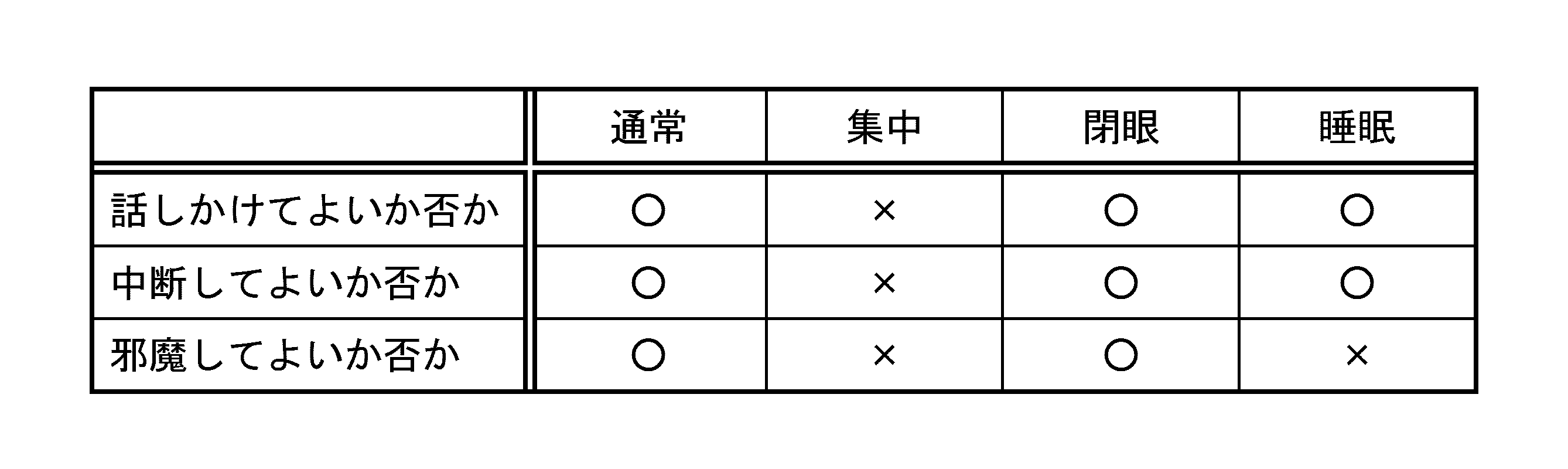
制御部501は、内側画像として表示されるコンテンツの情報に応じて、当該装置1又は3を装着したユーザー側から見える内側画像と、当該装置の外側から見える外側画像の表示動作をコントロールする。コンテンツ情報に応じた外側画像及び内側映像の表示制御方法の一例を、以下の表5にまとめておく。 C-4. The image control control unit 501 corresponding to the display content includes an inner image that can be seen from the user wearing the device 1 or 3 and an outer image that can be seen from the outside of the device, according to information on the content displayed as the inner image. Control display behavior. An example of a display control method for the outer image and the inner video according to the content information is summarized in Table 5 below.

本明細書の開示の技術は、以下のような構成をとることも可能である。 D. Configuration Example of Technology Disclosed in this Specification The technology disclosed in this specification can also take the following configurations.
を具備する画像表示装置。
(2)前記表示部は、前記ユーザー側から見える場所に配設され前記内側画像を表示する第1の表示デバイスと、前記画像表示装置の外側から見える場所に配設され前記外側画像を表示する第2の表示デバイスを備える、上記(1)に記載の画像表示装置。
(3)前記表示部は、前記内側画像及び前記外側画像を表示する単一の表示デバイスと、前記表示デバイスに表示された前記内側画像を前記ユーザー側から見える場所に導くとともに前記表示デバイスに表示された外側画像を前記画像表示装置の外側から見える場所に導く導光部を備える、上記(1)に記載の画像表示装置。
(4)前記外側画像を前記画像表示装置の外側に向けて投影する投影部をさらに備える、上記(1)に記載の画像表示装置。
(5)前記ユーザーが入力操作を行なう入力操作部をさらに備え、前記制御部は、前記ユーザーによる入力操作に応じて、前記内側画像並びに前記外側画像の表示を制御する、上記(1)に記載の画像表示装置。
(6)前記制御部は、前記ユーザーの前記入力操作部に対する入力操作に応じて、前記内側画像又は前記外側画像の表示オン/オフ、前記内側画像又は前記外側画像の色調整、前記内側画像又は前記外側画像の輝度調整、前記外側画像の表示サイズ切り換え、又は、前記外側画像の表示エリア移動を行なう、上記(5)に記載の画像表示装置。
(7)前記制御部は、前記ユーザーの前記入力操作部に対する入力操作に応じて、前記外側画像として、前記内側画像と同じ画像、前記内側画像とは異なる画像、周囲環境の情報、前記ユーザーの現在の状態のうち少なくとも1つを表示させる、上記(5)に記載の画像表示装置。
(8)前記制御部は、前記ユーザーの瞬目動作又は眼球の運動に基づく入力操作に応じて、前記外側画像の表示を切り替える、上記(5)に記載の画像表示装置。
(9)前記制御部は、前記ユーザーの前記入力操作部に対する入力操作に応じて、前記外側画像を前記内側画像として表示させる、上記(5)に記載の画像表示装置。
(10)前記制御部は、前記ユーザーの前記入力操作部に対する入力操作に応じて、前記外側画像又は前記内側画像に対する操作を禁止し、又は、禁止を解除する、上記(5)に記載の画像表示装置。
(11)前記制御部は、前記ユーザーの前記入力操作部に対する入力操作に応じて、前記外側画像の連続表示、間欠表示、又は所定時間毎の表示のいずれかを行なわせる、上記(5)に記載の画像表示装置。
(12)前記画像表示装置の周囲環境に関する情報を取得する環境情報取得部をさらに備え、前記制御部は、前記周囲環境に基づいて、前記内側画像と前記外側画像の表示を制御する、上記(1)に記載の画像表示装置。
(13)前記制御部は、環境光の明暗変化を検出したことに応答して、前記外側画像の輝度を制御する、上記(12)に記載の画像表示装置。
(14)前記制御部は、現在時刻の経過に応答して、前記外側画像の間欠表示又はタイマー表示を制御する、上記(12)に記載の画像表示装置。
(15)前記制御部は、周囲にいる人数に応じて、前記外側画像の表示オン/オフ、輝度レベル、表示エリア、表示サイズを制御する、上記(12)に記載の画像表示装置。
(16)前記ユーザーの状態に関する情報を取得する状態情報取得部をさらに備え、前記制御部は、前記ユーザーの状態に基づいて、前記内側画像と前記外側画像の表示を制御する、上記(1)に記載の画像表示装置。
(17)前記制御部は、前記状態情報取得部が取得した前記ユーザーの現在の作業状態、行動状態、精神状態、又は生理状態を、前記外側画像として表示する、上記(16)に記載の画像表示装置。
(18)前記制御部は、前記ユーザーの瞬目動作の情報に基づいて前記ユーザーの精神状態を特定し、前記精神状態に応じて前記外側画像の表示を制御する、上記(16)に記載の画像表示装置。
(19)前記制御部は、前記状態情報取得部が取得した前記ユーザーの現在の行動状態に適合するように前記外側画像の表示を制御する、上記(16)に記載の画像表示装置。
(20)前記制御部は、前記ユーザーの頭部の横の傾きに応じて、前記外側画像内の文字情報を水平に保つように制御する、上記(16)に記載の画像表示装置。
(21)前記制御部は、前記ユーザーの頭部の回転に応じて、前記内側画像又は前記外側画像の位置を保つように制御する、上記(16)に記載の画像表示装置。
(22)前記内側表示部に表示する画像コンテンツに関するコンテンツ情報を取得するコンテンツ情報取得部をさらに備え、前記制御部は、前記コンテンツ情報に応じて、前記外側画像の表示を制御する、上記(1)に記載の画像表示装置。
(23)ユーザーの頭部又は顔部に装着して用いられる画像表示方法であって、前記ユーザー側から見える内側画像を表示する第1の表示ステップと、前記画像表示装置の外部から見える外側画像を表示する第2の表示ステップと、前記内側画像と前記外側画像の表示を制御する制御ステップと、を有する画像表示方法。
(24)ユーザーの頭部又は顔部に装着して用いられる画像表示装置を制御するコンピューター・プログラムを記録したコンピューターに読み取り可能な記録媒体であって、前記コンピューター・プログラムは前記コンピューターを、前記ユーザー側から見える内側画像を表示させる第1の表示部、前記画像表示装置の外部から見える外側画像を表示させる第2の表示部、前記内側画像と前記外側画像の表示を制御する制御部、として機能させる、記録媒体。 (1) An image display device used by being mounted on a user's head or face, the first display unit displaying an inner image visible from the user side, and an outer image visible from the outside of the image display device A second display unit that displays, a control unit that controls display of the inner image and the outer image,
An image display device comprising:
(2) The display unit is disposed in a place visible from the user side and displays the inner image, and is disposed in a place visible from the outside of the image display device and displays the outer image. The image display device according to (1), including a second display device.
(3) The display unit guides the inner image displayed on the display device to a place visible from the user side and displays the inner image displayed on the display device while displaying the inner image and the outer image. The image display device according to (1), further including a light guide unit that guides the formed outside image to a place that can be seen from the outside of the image display device.
(4) The image display device according to (1), further including a projection unit that projects the outer image toward the outside of the image display device.
(5) The apparatus according to (1), further including an input operation unit in which the user performs an input operation, wherein the control unit controls display of the inner image and the outer image according to the input operation by the user. Image display device.
(6) The control unit turns on / off the display of the inner image or the outer image, adjusts the color of the inner image or the outer image, the inner image or the outer image according to an input operation on the input operation unit by the user. The image display device according to (5), wherein brightness adjustment of the outer image, display size switching of the outer image, or display area movement of the outer image is performed.
(7) In response to an input operation performed on the input operation unit by the user, the control unit, as the outer image, is the same image as the inner image, an image different from the inner image, information on the surrounding environment, the user's information The image display device according to (5), wherein at least one of current states is displayed.
(8) The image display device according to (5), wherein the control unit switches display of the outer image in accordance with an input operation based on the user's blink operation or eyeball movement.
(9) The image display device according to (5), wherein the control unit displays the outer image as the inner image in response to an input operation performed on the input operation unit by the user.
(10) The image according to (5), wherein the control unit prohibits or cancels the operation on the outer image or the inner image in accordance with an input operation on the input operation unit by the user. Display device.
(11) In the above (5), the control unit causes the external image to be continuously displayed, intermittently displayed, or displayed at predetermined time intervals in accordance with an input operation to the input operation unit by the user. The image display device described.
(12) The image processing apparatus further includes an environment information acquisition unit that acquires information related to the surrounding environment of the image display device, and the control unit controls display of the inner image and the outer image based on the surrounding environment. The image display device according to 1).
(13) The image display device according to (12), wherein the control unit controls the luminance of the outer image in response to detecting a change in brightness of ambient light.
(14) The image display device according to (12), wherein the control unit controls intermittent display or timer display of the outer image in response to elapse of a current time.
(15) The image display device according to (12), wherein the control unit controls display on / off, a luminance level, a display area, and a display size of the outer image according to the number of people around.
(16) The apparatus according to (1), further including a state information acquisition unit that acquires information related to the state of the user, wherein the control unit controls display of the inner image and the outer image based on the state of the user. The image display device described in 1.
(17) The image according to (16), wherein the control unit displays the user's current work state, action state, mental state, or physiological state acquired by the state information acquisition unit as the outer image. Display device.
(18) The control unit according to (16), wherein the control unit specifies the mental state of the user based on information on the user's blink operation, and controls display of the outer image according to the mental state. Image display device.
(19) The image display device according to (16), wherein the control unit controls display of the outer image so as to conform to the current behavior state of the user acquired by the state information acquisition unit.
(20) The image display device according to (16), wherein the control unit controls the character information in the outer image to be kept horizontal according to a horizontal inclination of the user's head.
(21) The image display device according to (16), wherein the control unit performs control so as to maintain a position of the inner image or the outer image according to rotation of the user's head.
(22) A content information acquisition unit that acquires content information related to image content to be displayed on the inner display unit, and the control unit controls display of the outer image according to the content information. ) Image display device.
(23) An image display method used by being mounted on a user's head or face, the first display step displaying an inner image visible from the user side, and an outer image visible from the outside of the image display device An image display method comprising: a second display step for displaying the image; and a control step for controlling display of the inner image and the outer image.
(24) A computer-readable recording medium storing a computer program for controlling an image display device used by being mounted on a user's head or face, wherein the computer program stores the computer as the user A first display unit that displays an inner image visible from the side, a second display unit that displays an outer image viewed from the outside of the image display device, and a control unit that controls display of the inner image and the outer image. Let the recording medium.
3…頭部装着型画像表示装置(透過性タイプ)
501…制御部、501A…ROM、501B…RAM
502…入力操作部、503…リモコン受信部
504…環境情報取得部、505…状態情報取得部
506…通信部、507…コンテンツ情報取得部
508…画像処理部
508-1…内側画像生成部、508-2…外側画像生成部
509、510…表示駆動部
511、512…表示パネル
513…虚像光学部、514…投影光学部
609…画像多重化部、610…表示駆動部
611…表示パネル、612…虚像・実像光学部
801…コリメート光学部、802…2分の1波長板
803…導光部、804…偏光ビーム・スプリッター
805…4分の1波長板、806…凹面鏡
807…スクリーン
2101…導光部、2102…ハーフ・ミラー
2103…凹面鏡、2104…コリメート光学部
2105…スクリーン
2201…導光部、2202…ハーフ・ミラー
2203…凹面鏡、2204…コリメート光学部
2205…投影光学部、2206…スクリーン 1. Head-mounted image display device (light-shielding type)
3… Head-mounted image display device (transmissible type)
501 ... Control unit, 501A ... ROM, 501B ... RAM
502 ... Input operation unit, 503 ... Remote control receiving unit 504 ... Environment information acquisition unit, 505 ... Status
Claims (20)
- ユーザーの頭部又は顔部に装着して用いられる画像表示装置であって、
前記ユーザー側から見える内側画像を表示する第1の表示部と、
前記画像表示装置の外部から見える外側画像を表示する第2の表示部と、
前記内側画像と前記外側画像の表示を制御する制御部と、
を具備する画像表示装置。 An image display device used on a user's head or face,
A first display unit for displaying an inner image visible from the user side;
A second display unit that displays an outer image that is visible from the outside of the image display device;
A control unit for controlling display of the inner image and the outer image;
An image display device comprising: - 前記表示部は、前記内側画像及び前記外側画像を表示する単一の表示デバイスと、前記表示デバイスに表示された前記内側画像を前記ユーザー側から見える場所に導くとともに、前記表示デバイスに表示された外側画像を前記画像表示装置の外側から見える場所に導く導光部を備える、
請求項1に記載の画像表示装置。 The display unit displays a single display device that displays the inner image and the outer image, and guides the inner image displayed on the display device to a location that is visible from the user side, and is displayed on the display device. A light guide unit that guides an outside image to a place visible from outside the image display device;
The image display device according to claim 1. - 前記外側画像を前記画像表示装置の外側に向けて投影する投影部をさらに備える、
請求項1に記載の画像表示装置。 A projection unit that projects the outside image toward the outside of the image display device;
The image display device according to claim 1. - 前記ユーザーが入力操作を行なう入力操作部をさらに備え、
前記制御部は、前記ユーザーによる入力操作に応じて、前記内側画像並びに前記外側画像の表示を制御する、
請求項1に記載の画像表示装置。 Further comprising an input operation unit for the user to perform an input operation,
The control unit controls display of the inner image and the outer image in accordance with an input operation by the user.
The image display device according to claim 1. - 前記制御部は、前記ユーザーの前記入力操作部に対する入力操作に応じて、前記内側画像又は前記外側画像の表示オン/オフ、前記内側画像又は前記外側画像の色調整、前記内側画像又は前記外側画像の輝度調整、前記外側画像の表示サイズ切り換え、又は、前記外側画像の表示エリア移動を行なう、
請求項4に記載の画像表示装置。 The control unit is configured to turn on / off display of the inner image or the outer image, color adjustment of the inner image or the outer image, the inner image, or the outer image according to an input operation performed on the input operation unit by the user. Brightness adjustment, switching the display size of the outer image, or moving the display area of the outer image,
The image display device according to claim 4. - 前記制御部は、前記ユーザーの前記入力操作部に対する入力操作に応じて、前記外側画像として、前記内側画像と同じ画像、前記内側画像とは異なる画像、周囲環境の情報、前記ユーザーの現在の状態のうち少なくとも1つを表示させ、又は、前記外側画像を前記内側画像として表示させる、
請求項4に記載の画像表示装置。 The control unit, as the outer image, the same image as the inner image, an image different from the inner image, information on the surrounding environment, the current state of the user, according to an input operation on the input operation unit by the user Display at least one of them, or display the outer image as the inner image,
The image display device according to claim 4. - 前記制御部は、前記ユーザーの瞬目動作又は眼球の運動に基づく入力操作に応じて、前記外側画像の表示を切り替える、
請求項4に記載の画像表示装置。 The control unit switches the display of the outer image according to an input operation based on the user's blink operation or eye movement.
The image display device according to claim 4. - 前記制御部は、前記ユーザーの前記入力操作部に対する入力操作に応じて、前記外側画像の連続表示、間欠表示、又は所定時間毎の表示のいずれかを行なわせる、
請求項4に記載の画像表示装置。 The control unit causes the outside image to be continuously displayed, intermittently displayed, or displayed at predetermined time intervals in response to an input operation performed on the input operation unit by the user.
The image display device according to claim 4. - 前記画像表示装置の周囲環境に関する情報を取得する環境情報取得部をさらに備え、
前記制御部は、前記周囲環境に基づいて、前記内側画像と前記外側画像の表示を制御する、
請求項1に記載の画像表示装置。 An environment information acquisition unit that acquires information about the surrounding environment of the image display device;
The control unit controls display of the inner image and the outer image based on the surrounding environment.
The image display device according to claim 1. - 前記制御部は、環境光の明暗変化を検出したことに応答して、前記外側画像の輝度を制御する、
請求項9に記載の画像表示装置。 In response to detecting a change in brightness of ambient light, the control unit controls the brightness of the outer image.
The image display device according to claim 9. - 前記制御部は、現在時刻の経過に応答して、前記外側画像の間欠表示又はタイマー表示を制御する、
請求項9に記載の画像表示装置。 The control unit controls intermittent display or timer display of the outer image in response to the elapse of the current time.
The image display device according to claim 9. - 前記制御部は、周囲にいる人数に応じて、前記外側画像の表示オン/オフ、輝度レベル、表示エリア、表示サイズを制御する、
請求項9に記載の画像表示装置。 The control unit controls display on / off, brightness level, display area, and display size of the outer image according to the number of people around.
The image display device according to claim 9. - 前記ユーザーの状態に関する情報を取得する状態情報取得部をさらに備え、
前記制御部は、前記ユーザーの状態に基づいて、前記内側画像と前記外側画像の表示を制御する、
請求項1に記載の画像表示装置。 A state information acquisition unit for acquiring information on the state of the user;
The control unit controls display of the inner image and the outer image based on the state of the user.
The image display device according to claim 1. - 前記制御部は、前記状態情報取得部が取得した前記ユーザーの現在の作業状態、行動状態、精神状態、又は生理状態を、前記外側画像として表示する、
請求項13に記載の画像表示装置。 The control unit displays the user's current working state, behavioral state, mental state, or physiological state acquired by the state information acquisition unit as the outer image.
The image display device according to claim 13. - 前記制御部は、前記ユーザーの瞬目動作の情報に基づいて前記ユーザーの精神状態を特定し、前記精神状態に応じて前記外側画像の表示を制御する、
請求項13に記載の画像表示装置。 The control unit identifies the user's mental state based on information on the user's blink operation, and controls display of the outer image according to the mental state.
The image display device according to claim 13. - 前記制御部は、前記ユーザーの頭部の横の傾きに応じて、前記外側画像内の文字情報を水平に保つように制御する、
請求項13に記載の画像表示装置。 The control unit controls the character information in the outer image to be kept horizontal according to the horizontal inclination of the user's head.
The image display device according to claim 13. - 前記制御部は、前記ユーザーの頭部の回転に応じて、前記内側画像又は前記外側画像の位置を保つように制御する、
請求項13に記載の画像表示装置。 The control unit controls the position of the inner image or the outer image according to the rotation of the user's head,
The image display device according to claim 13. - 前記内側表示部に表示する画像コンテンツに関するコンテンツ情報を取得するコンテンツ情報取得部をさらに備え、
前記制御部は、前記コンテンツ情報に応じて、前記外側画像の表示を制御する、
請求項1に記載の画像表示装置。 A content information acquisition unit that acquires content information related to image content to be displayed on the inner display unit;
The control unit controls display of the outer image according to the content information.
The image display device according to claim 1. - ユーザーの頭部又は顔部に装着して用いられる画像表示方法であって、
前記ユーザー側から見える内側画像を表示する第1の表示ステップと、
前記画像表示装置の外部から見える外側画像を表示する第2の表示ステップと、
前記内側画像と前記外側画像の表示を制御する制御ステップと、
を有する画像表示方法。 An image display method used by wearing on a user's head or face,
A first display step of displaying an inner image visible from the user side;
A second display step of displaying an outer image visible from the outside of the image display device;
A control step for controlling display of the inner image and the outer image;
An image display method comprising: - ユーザーの頭部又は顔部に装着して用いられる画像表示装置を制御するコンピューター・プログラムを記録したコンピューターに読み取り可能な記録媒体であって、前記コンピューター・プログラムは前記コンピューターを、
前記ユーザー側から見える内側画像を表示させる第1の表示部、
前記画像表示装置の外部から見える外側画像を表示させる第2の表示部、
前記内側画像と前記外側画像の表示を制御する制御部、
として機能させる、記録媒体。 A computer-readable recording medium recording a computer program for controlling an image display device used by being mounted on a user's head or face, wherein the computer program stores the computer,
A first display unit for displaying an inner image visible from the user side;
A second display unit for displaying an outer image visible from the outside of the image display device;
A control unit for controlling display of the inner image and the outer image;
As a recording medium.
Priority Applications (7)
| Application Number | Priority Date | Filing Date | Title |
|---|---|---|---|
| BR112015004958A BR112015004958A8 (en) | 2012-09-12 | 2013-07-01 | image display device and method, and computer readable recording media. |
| KR1020157001384A KR102044054B1 (en) | 2012-09-12 | 2013-07-01 | Image control device and image control method |
| CN201380046423.0A CN104603675B (en) | 2012-09-12 | 2013-07-01 | Image display, image display method and recording medium |
| US14/426,203 US9798144B2 (en) | 2012-09-12 | 2013-07-01 | Wearable image display device to control display of image |
| JP2014535407A JP6350283B2 (en) | 2012-09-12 | 2013-07-01 | Image display device, image display method, and recording medium |
| EP13836975.6A EP2896986B1 (en) | 2012-09-12 | 2013-07-01 | Image display device, image display method, and recording medium |
| US15/708,782 US20180003983A1 (en) | 2012-09-12 | 2017-09-19 | Image display device, image display method, and recording medium |
Applications Claiming Priority (2)
| Application Number | Priority Date | Filing Date | Title |
|---|---|---|---|
| JP2012-200902 | 2012-09-12 | ||
| JP2012200902 | 2012-09-12 |
Related Child Applications (2)
| Application Number | Title | Priority Date | Filing Date |
|---|---|---|---|
| US14/426,203 A-371-Of-International US9798144B2 (en) | 2012-09-12 | 2013-07-01 | Wearable image display device to control display of image |
| US15/708,782 Continuation US20180003983A1 (en) | 2012-09-12 | 2017-09-19 | Image display device, image display method, and recording medium |
Publications (1)
| Publication Number | Publication Date |
|---|---|
| WO2014041871A1 true WO2014041871A1 (en) | 2014-03-20 |
Family
ID=50278005
Family Applications (1)
| Application Number | Title | Priority Date | Filing Date |
|---|---|---|---|
| PCT/JP2013/068002 WO2014041871A1 (en) | 2012-09-12 | 2013-07-01 | Image display device, image display method, and recording medium |
Country Status (7)
| Country | Link |
|---|---|
| US (2) | US9798144B2 (en) |
| EP (1) | EP2896986B1 (en) |
| JP (2) | JP6350283B2 (en) |
| KR (1) | KR102044054B1 (en) |
| CN (1) | CN104603675B (en) |
| BR (1) | BR112015004958A8 (en) |
| WO (1) | WO2014041871A1 (en) |
Cited By (6)
| Publication number | Priority date | Publication date | Assignee | Title |
|---|---|---|---|---|
| CN104951259A (en) * | 2014-03-28 | 2015-09-30 | 索尼公司 | Display device and display control method thereof |
| JP2016109760A (en) * | 2014-12-03 | 2016-06-20 | 日本電信電話株式会社 | Display device and display method |
| US20180088452A1 (en) * | 2015-04-20 | 2018-03-29 | Sony Corporation | Light source device, projection display unit, and display system |
| JP2021512402A (en) * | 2018-02-02 | 2021-05-13 | インターデジタル シーイー パテント ホールディングス | Multi-viewing virtual reality user interface |
| US11125998B2 (en) * | 2014-01-02 | 2021-09-21 | Nokia Technologies Oy | Apparatus or method for projecting light internally towards and away from an eye of a user |
| JP7459375B2 (en) | 2020-09-26 | 2024-04-01 | アップル インコーポレイテッド | Systems, methods, and graphical user interfaces for updating a device's display relative to a user's body |
Families Citing this family (119)
| Publication number | Priority date | Publication date | Assignee | Title |
|---|---|---|---|---|
| US9298007B2 (en) | 2014-01-21 | 2016-03-29 | Osterhout Group, Inc. | Eye imaging in head worn computing |
| US9229233B2 (en) | 2014-02-11 | 2016-01-05 | Osterhout Group, Inc. | Micro Doppler presentations in head worn computing |
| US9965681B2 (en) | 2008-12-16 | 2018-05-08 | Osterhout Group, Inc. | Eye imaging in head worn computing |
| US9952664B2 (en) | 2014-01-21 | 2018-04-24 | Osterhout Group, Inc. | Eye imaging in head worn computing |
| WO2014041872A1 (en) * | 2012-09-12 | 2014-03-20 | ソニー株式会社 | Image display device |
| KR20150041453A (en) * | 2013-10-08 | 2015-04-16 | 엘지전자 주식회사 | Wearable glass-type image display device and control method thereof |
| CN103646587B (en) * | 2013-12-05 | 2017-02-22 | 北京京东方光电科技有限公司 | deaf-mute people |
| US20150228119A1 (en) | 2014-02-11 | 2015-08-13 | Osterhout Group, Inc. | Spatial location presentation in head worn computing |
| US9829707B2 (en) | 2014-08-12 | 2017-11-28 | Osterhout Group, Inc. | Measuring content brightness in head worn computing |
| US9594246B2 (en) | 2014-01-21 | 2017-03-14 | Osterhout Group, Inc. | See-through computer display systems |
| US9746686B2 (en) | 2014-05-19 | 2017-08-29 | Osterhout Group, Inc. | Content position calibration in head worn computing |
| US10254856B2 (en) | 2014-01-17 | 2019-04-09 | Osterhout Group, Inc. | External user interface for head worn computing |
| US20160019715A1 (en) | 2014-07-15 | 2016-01-21 | Osterhout Group, Inc. | Content presentation in head worn computing |
| US10649220B2 (en) | 2014-06-09 | 2020-05-12 | Mentor Acquisition One, Llc | Content presentation in head worn computing |
| US9299194B2 (en) | 2014-02-14 | 2016-03-29 | Osterhout Group, Inc. | Secure sharing in head worn computing |
| US9575321B2 (en) | 2014-06-09 | 2017-02-21 | Osterhout Group, Inc. | Content presentation in head worn computing |
| US9841599B2 (en) | 2014-06-05 | 2017-12-12 | Osterhout Group, Inc. | Optical configurations for head-worn see-through displays |
| US10684687B2 (en) | 2014-12-03 | 2020-06-16 | Mentor Acquisition One, Llc | See-through computer display systems |
| US10191279B2 (en) | 2014-03-17 | 2019-01-29 | Osterhout Group, Inc. | Eye imaging in head worn computing |
| US9939934B2 (en) | 2014-01-17 | 2018-04-10 | Osterhout Group, Inc. | External user interface for head worn computing |
| US11103122B2 (en) | 2014-07-15 | 2021-08-31 | Mentor Acquisition One, Llc | Content presentation in head worn computing |
| US11669163B2 (en) | 2014-01-21 | 2023-06-06 | Mentor Acquisition One, Llc | Eye glint imaging in see-through computer display systems |
| US12093453B2 (en) | 2014-01-21 | 2024-09-17 | Mentor Acquisition One, Llc | Eye glint imaging in see-through computer display systems |
| US9811159B2 (en) | 2014-01-21 | 2017-11-07 | Osterhout Group, Inc. | Eye imaging in head worn computing |
| US9532715B2 (en) | 2014-01-21 | 2017-01-03 | Osterhout Group, Inc. | Eye imaging in head worn computing |
| US9811152B2 (en) | 2014-01-21 | 2017-11-07 | Osterhout Group, Inc. | Eye imaging in head worn computing |
| US20150205135A1 (en) | 2014-01-21 | 2015-07-23 | Osterhout Group, Inc. | See-through computer display systems |
| US11892644B2 (en) | 2014-01-21 | 2024-02-06 | Mentor Acquisition One, Llc | See-through computer display systems |
| US11737666B2 (en) | 2014-01-21 | 2023-08-29 | Mentor Acquisition One, Llc | Eye imaging in head worn computing |
| US9494800B2 (en) | 2014-01-21 | 2016-11-15 | Osterhout Group, Inc. | See-through computer display systems |
| US11487110B2 (en) | 2014-01-21 | 2022-11-01 | Mentor Acquisition One, Llc | Eye imaging in head worn computing |
| US9766463B2 (en) | 2014-01-21 | 2017-09-19 | Osterhout Group, Inc. | See-through computer display systems |
| US9836122B2 (en) | 2014-01-21 | 2017-12-05 | Osterhout Group, Inc. | Eye glint imaging in see-through computer display systems |
| US9753288B2 (en) | 2014-01-21 | 2017-09-05 | Osterhout Group, Inc. | See-through computer display systems |
| US9746676B2 (en) | 2014-01-21 | 2017-08-29 | Osterhout Group, Inc. | See-through computer display systems |
| US9401540B2 (en) | 2014-02-11 | 2016-07-26 | Osterhout Group, Inc. | Spatial location presentation in head worn computing |
| US9852545B2 (en) | 2014-02-11 | 2017-12-26 | Osterhout Group, Inc. | Spatial location presentation in head worn computing |
| US20160187651A1 (en) | 2014-03-28 | 2016-06-30 | Osterhout Group, Inc. | Safety for a vehicle operator with an hmd |
| US9651787B2 (en) | 2014-04-25 | 2017-05-16 | Osterhout Group, Inc. | Speaker assembly for headworn computer |
| US10853589B2 (en) | 2014-04-25 | 2020-12-01 | Mentor Acquisition One, Llc | Language translation with head-worn computing |
| US10663740B2 (en) | 2014-06-09 | 2020-05-26 | Mentor Acquisition One, Llc | Content presentation in head worn computing |
| US9684172B2 (en) | 2014-12-03 | 2017-06-20 | Osterhout Group, Inc. | Head worn computer display systems |
| USD751552S1 (en) | 2014-12-31 | 2016-03-15 | Osterhout Group, Inc. | Computer glasses |
| US9740282B1 (en) * | 2015-01-05 | 2017-08-22 | Amazon Technologies, Inc. | Gaze direction tracking |
| US10878775B2 (en) * | 2015-02-17 | 2020-12-29 | Mentor Acquisition One, Llc | See-through computer display systems |
| US20160239985A1 (en) * | 2015-02-17 | 2016-08-18 | Osterhout Group, Inc. | See-through computer display systems |
| EP3059658A1 (en) * | 2015-02-18 | 2016-08-24 | Nokia Technologies OY | Apparatus, methods and computer programs for providing images |
| EP3062142B1 (en) | 2015-02-26 | 2018-10-03 | Nokia Technologies OY | Apparatus for a near-eye display |
| KR101648017B1 (en) * | 2015-03-23 | 2016-08-12 | 현대자동차주식회사 | Display apparatus, vehicle and display method |
| US9939644B2 (en) * | 2015-06-25 | 2018-04-10 | Intel Corporation | Technologies for controlling vision correction of a wearable computing device |
| US10545714B2 (en) | 2015-09-04 | 2020-01-28 | Samsung Electronics Co., Ltd. | Dual screen head mounted display |
| CN107615134B (en) * | 2015-10-23 | 2020-03-24 | 深圳市柔宇科技有限公司 | Head-mounted display device |
| WO2017067002A1 (en) * | 2015-10-23 | 2017-04-27 | 深圳市柔宇科技有限公司 | Head-mounted display device |
| DE102015014450B4 (en) * | 2015-11-07 | 2017-11-23 | Audi Ag | Virtual reality glasses and method of operating a virtual reality glasses |
| US20170230640A1 (en) * | 2016-02-05 | 2017-08-10 | Samsung Electronics Co., Ltd. | Portable image device with external display |
| US10591728B2 (en) | 2016-03-02 | 2020-03-17 | Mentor Acquisition One, Llc | Optical systems for head-worn computers |
| US10667981B2 (en) | 2016-02-29 | 2020-06-02 | Mentor Acquisition One, Llc | Reading assistance system for visually impaired |
| EP3625724B1 (en) | 2016-05-18 | 2023-07-26 | COLOP Digital GmbH | A method to authenticate a substrate using speckle patterns and a device to perform the method |
| US10522109B2 (en) * | 2016-06-14 | 2019-12-31 | Lenovo (Singapore) Pte. Ltd. | Adjusting brightness settings based on context data |
| US10268438B2 (en) * | 2016-06-30 | 2019-04-23 | Sony Interactive Entertainment Inc. | Display screen front panel of HMD for viewing by users viewing the HMD player |
| KR20180050143A (en) | 2016-11-04 | 2018-05-14 | 삼성전자주식회사 | Method and device for acquiring information by capturing eye |
| US10650552B2 (en) | 2016-12-29 | 2020-05-12 | Magic Leap, Inc. | Systems and methods for augmented reality |
| EP3343267B1 (en) | 2016-12-30 | 2024-01-24 | Magic Leap, Inc. | Polychromatic light out-coupling apparatus, near-eye displays comprising the same, and method of out-coupling polychromatic light |
| JP2018142857A (en) * | 2017-02-28 | 2018-09-13 | セイコーエプソン株式会社 | Head mounted display device, program, and control method of head mounted display device |
| US10183231B1 (en) * | 2017-03-01 | 2019-01-22 | Perine Lowe, Inc. | Remotely and selectively controlled toy optical viewer apparatus and method of use |
| US10488920B2 (en) * | 2017-06-02 | 2019-11-26 | Htc Corporation | Immersive headset system and control method thereof |
| US11861255B1 (en) | 2017-06-16 | 2024-01-02 | Apple Inc. | Wearable device for facilitating enhanced interaction |
| CN107065196B (en) * | 2017-06-16 | 2019-03-15 | 京东方科技集团股份有限公司 | A kind of augmented reality display device and augmented reality display methods |
| CN107422478B (en) * | 2017-06-21 | 2023-07-25 | 深圳传音通讯有限公司 | Virtual reality head-mounted device capable of being observed externally |
| US10578870B2 (en) | 2017-07-26 | 2020-03-03 | Magic Leap, Inc. | Exit pupil expander |
| EP3672697B1 (en) * | 2017-08-24 | 2024-08-07 | Vuzix Corporation | Waterproof ar goggle system |
| JP7282090B2 (en) | 2017-12-10 | 2023-05-26 | マジック リープ, インコーポレイテッド | Antireflection coating on optical waveguide |
| KR20200100720A (en) * | 2017-12-20 | 2020-08-26 | 매직 립, 인코포레이티드 | Insert for augmented reality viewing device |
| US11435583B1 (en) * | 2018-01-17 | 2022-09-06 | Apple Inc. | Electronic device with back-to-back displays |
| WO2019178567A1 (en) | 2018-03-15 | 2019-09-19 | Magic Leap, Inc. | Image correction due to deformation of components of a viewing device |
| CN108668008B (en) * | 2018-03-30 | 2021-04-16 | Oppo广东移动通信有限公司 | Electronic device, display parameter adjusting method and device, and computer-readable storage medium |
| JP2019184807A (en) * | 2018-04-10 | 2019-10-24 | 株式会社ジャパンディスプレイ | Head mount display |
| US10345902B1 (en) * | 2018-04-24 | 2019-07-09 | Dell Products, Lp | Method and apparatus for maintaining a secure head-mounted display session |
| US10747309B2 (en) * | 2018-05-10 | 2020-08-18 | Microsoft Technology Licensing, Llc | Reconfigurable optics for switching between near-to-eye display modes |
| WO2019231850A1 (en) | 2018-05-31 | 2019-12-05 | Magic Leap, Inc. | Radar head pose localization |
| US10642369B2 (en) * | 2018-06-14 | 2020-05-05 | Dell Products, L.P. | Distinguishing between one-handed and two-handed gesture sequences in virtual, augmented, and mixed reality (xR) applications |
| US10962783B2 (en) | 2018-06-19 | 2021-03-30 | Apple Inc. | Electronic devices having electrically adjustable optical layers |
| WO2020010097A1 (en) | 2018-07-02 | 2020-01-09 | Magic Leap, Inc. | Pixel intensity modulation using modifying gain values |
| US11856479B2 (en) | 2018-07-03 | 2023-12-26 | Magic Leap, Inc. | Systems and methods for virtual and augmented reality along a route with markers |
| US11510027B2 (en) | 2018-07-03 | 2022-11-22 | Magic Leap, Inc. | Systems and methods for virtual and augmented reality |
| WO2020023543A1 (en) | 2018-07-24 | 2020-01-30 | Magic Leap, Inc. | Viewing device with dust seal integration |
| US11598651B2 (en) | 2018-07-24 | 2023-03-07 | Magic Leap, Inc. | Temperature dependent calibration of movement detection devices |
| WO2020028834A1 (en) | 2018-08-02 | 2020-02-06 | Magic Leap, Inc. | A viewing system with interpupillary distance compensation based on head motion |
| JP7438188B2 (en) | 2018-08-03 | 2024-02-26 | マジック リープ, インコーポレイテッド | Unfused pose-based drift correction of fused poses of totems in user interaction systems |
| EP3840645A4 (en) | 2018-08-22 | 2021-10-20 | Magic Leap, Inc. | Patient viewing system |
| US11982809B2 (en) * | 2018-09-17 | 2024-05-14 | Apple Inc. | Electronic device with inner display and externally accessible input-output device |
| US11899214B1 (en) | 2018-09-18 | 2024-02-13 | Apple Inc. | Head-mounted device with virtually shifted component locations using a double-folded light path |
| CN109188700B (en) * | 2018-10-30 | 2021-05-11 | 京东方科技集团股份有限公司 | Optical display system and AR/VR display device |
| EP3881279A4 (en) * | 2018-11-16 | 2022-08-17 | Magic Leap, Inc. | Image size triggered clarification to maintain image sharpness |
| CN111323919A (en) * | 2018-12-17 | 2020-06-23 | 施轩杰 | Structure scheme for sharing display and double-sided imaging |
| JP7543274B2 (en) | 2018-12-21 | 2024-09-02 | マジック リープ, インコーポレイテッド | Air pocket structures for enhancing total internal reflection in waveguides. |
| CN113168800A (en) * | 2018-12-28 | 2021-07-23 | 深圳市柔宇科技股份有限公司 | Screen control method and terminal of display screen and computer readable storage medium |
| CN113544766A (en) | 2019-03-12 | 2021-10-22 | 奇跃公司 | Registering local content between first and second augmented reality viewers |
| CN110162248A (en) * | 2019-04-22 | 2019-08-23 | 西安万像电子科技有限公司 | Display processing method, apparatus and system |
| WO2020235306A1 (en) * | 2019-05-17 | 2020-11-26 | 株式会社東海理化電機製作所 | Control system and presentation system |
| JP2022542363A (en) | 2019-07-26 | 2022-10-03 | マジック リープ, インコーポレイテッド | Systems and methods for augmented reality |
| US11740742B2 (en) * | 2019-09-23 | 2023-08-29 | Apple Inc. | Electronic devices with finger sensors |
| CN114730490A (en) | 2019-11-14 | 2022-07-08 | 奇跃公司 | System and method for virtual reality and augmented reality |
| WO2021097323A1 (en) | 2019-11-15 | 2021-05-20 | Magic Leap, Inc. | A viewing system for use in a surgical environment |
| US11347060B2 (en) * | 2019-12-02 | 2022-05-31 | Arm Limited | Device and method of controlling device |
| WO2021142015A1 (en) * | 2020-01-06 | 2021-07-15 | Sourcepicture, Inc. | Systems and methods for adapting playback device for content display |
| US20210390784A1 (en) * | 2020-06-15 | 2021-12-16 | Snap Inc. | Smart glasses with outward-facing display |
| US11380022B2 (en) * | 2020-10-22 | 2022-07-05 | Sony Group Corporation | Content modification in a shared session among multiple head-mounted display devices |
| JP2022102681A (en) * | 2020-12-25 | 2022-07-07 | ソフトバンク株式会社 | Spectacle-type device, program, and control method |
| US11796801B2 (en) * | 2021-05-24 | 2023-10-24 | Google Llc | Reducing light leakage via external gaze detection |
| US11852822B2 (en) | 2021-07-09 | 2023-12-26 | Realwear, Inc. | Convertible waveguide optical engine assembly for head-mounted device |
| US11940627B2 (en) * | 2021-07-09 | 2024-03-26 | Realwear, Inc. | Opaque waveguide optical engine assembly for head-mounted device |
| US11808945B2 (en) * | 2021-09-07 | 2023-11-07 | Meta Platforms Technologies, Llc | Eye data and operation of head mounted device |
| US12092822B2 (en) | 2022-06-30 | 2024-09-17 | Vuzix Corporation | Multi-antenna augmented reality display |
| WO2024043519A1 (en) * | 2022-08-24 | 2024-02-29 | 삼성전자주식회사 | Method for controlling multiple displays and electronic device supporting same |
| WO2024058472A1 (en) * | 2022-09-15 | 2024-03-21 | 삼성전자주식회사 | Wearable device for providing information on application through external display and method for controlling same |
| WO2024071537A1 (en) * | 2022-09-26 | 2024-04-04 | 엘지전자 주식회사 | Vehicle imaging device with large aspect ratio using projection optical system |
| US20240281056A1 (en) * | 2023-02-16 | 2024-08-22 | Microsoft Technology Licensing, Llc | Muscle group movement tracking using rf sensors |
| US11972526B1 (en) | 2023-03-31 | 2024-04-30 | Apple Inc. | Rendering of enrolled user's face for external display |
Citations (11)
| Publication number | Priority date | Publication date | Assignee | Title |
|---|---|---|---|---|
| JPH05328257A (en) * | 1992-05-26 | 1993-12-10 | Olympus Optical Co Ltd | Head mount type display device |
| JP2000075815A (en) | 1998-08-31 | 2000-03-14 | Toppan Printing Co Ltd | Double-sided liquid crystal display device |
| US6198523B1 (en) | 1999-10-28 | 2001-03-06 | Hewlett-Packard Co. | Ferroelectric liquid crystal light doubler with temperature and voltage controlled tilt angle |
| JP2001100144A (en) * | 1999-09-30 | 2001-04-13 | Olympus Optical Co Ltd | Face mounted type video display device for medical treatment |
| JP2007251331A (en) | 2006-03-14 | 2007-09-27 | Seiko Epson Corp | Double sided display apparatus for video image, and sound output method |
| JP2008065169A (en) * | 2006-09-08 | 2008-03-21 | Sony Corp | Display device and display method |
| JP2010139688A (en) * | 2008-12-11 | 2010-06-24 | Panasonic Corp | Image projection device |
| JP2011048424A (en) | 2009-08-25 | 2011-03-10 | Square Enix Co Ltd | Server, method and program for community support |
| JP2012042654A (en) | 2010-08-18 | 2012-03-01 | Sony Corp | Display device |
| JP2012093767A (en) * | 2011-11-28 | 2012-05-17 | Olympus Corp | Information display apparatus |
| JP2012141461A (en) | 2010-12-29 | 2012-07-26 | Sony Corp | Head mount display |
Family Cites Families (50)
| Publication number | Priority date | Publication date | Assignee | Title |
|---|---|---|---|---|
| FR2647556B1 (en) * | 1989-05-23 | 1993-10-29 | Thomson Csf | OPTICAL DEVICE FOR INTRODUCING A COLLIMATED IMAGE INTO THE VISUAL FIELD OF AN OBSERVER AND HELMET COMPRISING AT LEAST ONE SUCH DEVICE |
| US5130794A (en) * | 1990-03-29 | 1992-07-14 | Ritchey Kurtis J | Panoramic display system |
| US5991085A (en) * | 1995-04-21 | 1999-11-23 | I-O Display Systems Llc | Head-mounted personal visual display apparatus with image generator and holder |
| US5880733A (en) * | 1996-04-30 | 1999-03-09 | Microsoft Corporation | Display system and method for displaying windows of an operating system to provide a three-dimensional workspace for a computer system |
| EP0818701B1 (en) * | 1996-07-09 | 2002-10-02 | Harness System Technologies Research, Ltd. | Display device |
| US6118888A (en) * | 1997-02-28 | 2000-09-12 | Kabushiki Kaisha Toshiba | Multi-modal interface apparatus and method |
| JP4245750B2 (en) * | 1999-10-15 | 2009-04-02 | オリンパス株式会社 | Stereoscopic observation device |
| US7233908B1 (en) * | 2000-11-03 | 2007-06-19 | Quality Data Management, Inc. | Method and system for presentation of survey and report data |
| JP2004199027A (en) | 2002-10-24 | 2004-07-15 | Seiko Epson Corp | Display device and electronic equipment |
| KR100580619B1 (en) * | 2002-12-11 | 2006-05-16 | 삼성전자주식회사 | Apparatus and method of managing dialog between user and agent |
| WO2004109349A2 (en) * | 2003-06-10 | 2004-12-16 | Elop Electro-Optics Industries Ltd. | Method and system for displaying an informative image against a background image |
| JP4600290B2 (en) * | 2004-01-29 | 2010-12-15 | コニカミノルタホールディングス株式会社 | Visual auxiliary display device |
| WO2006086223A2 (en) * | 2005-02-08 | 2006-08-17 | Blue Belt Technologies, Inc. | Augmented reality device and method |
| CA2605239A1 (en) * | 2005-05-02 | 2006-11-09 | University Of Virginia Patent Foundation | Systems, devices, and methods for interpreting movement |
| US20070035546A1 (en) * | 2005-08-11 | 2007-02-15 | Kim Hyun O | Animation composing vending machine |
| US7493566B2 (en) * | 2005-12-19 | 2009-02-17 | International Business Machines Corporation | Display of information for two oppositely situated users |
| US20070176847A1 (en) * | 2005-12-30 | 2007-08-02 | Shah Kamalesh R | Method and system to reduce display power consumption |
| US9101279B2 (en) * | 2006-02-15 | 2015-08-11 | Virtual Video Reality By Ritchey, Llc | Mobile user borne brain activity data and surrounding environment data correlation system |
| US7853566B2 (en) * | 2006-08-04 | 2010-12-14 | Apple Inc. | Navigation of electronic backups |
| EP2053963A2 (en) * | 2006-08-17 | 2009-05-06 | Koninklijke Philips Electronics N.V. | Dynamic body state display device |
| JP2008067219A (en) * | 2006-09-08 | 2008-03-21 | Sony Corp | Imaging apparatus and imaging method |
| JP4901534B2 (en) * | 2007-03-02 | 2012-03-21 | 株式会社デンソー | Information communication system, facility side device, user side device, state detection device, update device, facility side device program, user side device program, state detection device program, and update device program |
| US20090024050A1 (en) * | 2007-03-30 | 2009-01-22 | Searete Llc, A Limited Liability Corporation Of The State Of Delaware | Computational user-health testing |
| US9317110B2 (en) * | 2007-05-29 | 2016-04-19 | Cfph, Llc | Game with hand motion control |
| US8099392B2 (en) * | 2007-06-08 | 2012-01-17 | Apple Inc. | Electronic backup of applications |
| US8217995B2 (en) * | 2008-01-18 | 2012-07-10 | Lockheed Martin Corporation | Providing a collaborative immersive environment using a spherical camera and motion capture |
| US20090213038A1 (en) * | 2008-02-25 | 2009-08-27 | Joseph Huang | Head Mounted Display and Real-Time Video Device |
| US8957835B2 (en) * | 2008-09-30 | 2015-02-17 | Apple Inc. | Head-mounted display apparatus for retaining a portable electronic device with display |
| JP2010134057A (en) * | 2008-12-02 | 2010-06-17 | Brother Ind Ltd | Head-mounted display |
| JP5262688B2 (en) * | 2008-12-24 | 2013-08-14 | ブラザー工業株式会社 | Presentation system and program thereof |
| EP2254109A1 (en) * | 2009-05-20 | 2010-11-24 | Dialog Semiconductor GmbH | Tagged multi line address driving |
| JP5287683B2 (en) * | 2009-11-26 | 2013-09-11 | セイコーエプソン株式会社 | Head mounted display |
| KR101673032B1 (en) * | 2010-01-25 | 2016-11-04 | 엘지전자 주식회사 | Video communication method and digital television thereof |
| US8503539B2 (en) * | 2010-02-26 | 2013-08-06 | Bao Tran | High definition personal computer (PC) cam |
| US9994228B2 (en) * | 2010-05-14 | 2018-06-12 | Iarmourholdings, Inc. | Systems and methods for controlling a vehicle or device in response to a measured human response to a provocative environment |
| TW201142778A (en) * | 2010-05-18 | 2011-12-01 | Ind Tech Res Inst | Pixel structure and circuit of pixel having multi-display-medium |
| US8384770B2 (en) * | 2010-06-02 | 2013-02-26 | Nintendo Co., Ltd. | Image display system, image display apparatus, and image display method |
| EP2418865A3 (en) * | 2010-08-09 | 2014-08-06 | LG Electronics Inc. | 3D viewing device, image display apparatus, and method for operating the same |
| US8819726B2 (en) * | 2010-10-14 | 2014-08-26 | Cyandia, Inc. | Methods, apparatus, and systems for presenting television programming and related information |
| US9690099B2 (en) * | 2010-12-17 | 2017-06-27 | Microsoft Technology Licensing, Llc | Optimized focal area for augmented reality displays |
| EP4036630A1 (en) * | 2010-12-24 | 2022-08-03 | Magic Leap, Inc. | Image display system |
| US9898556B2 (en) * | 2011-06-20 | 2018-02-20 | Ford Global Technology, Llc | Immersive dimensional variation |
| CN106961621A (en) * | 2011-12-29 | 2017-07-18 | 英特尔公司 | Use the communication of incarnation |
| US20130169545A1 (en) * | 2011-12-29 | 2013-07-04 | Research In Motion Corporation | Cooperative displays |
| US8982471B1 (en) * | 2012-01-04 | 2015-03-17 | Google Inc. | HMD image source as dual-purpose projector/near-eye display |
| US8862104B2 (en) * | 2012-06-29 | 2014-10-14 | Intel Corporation | System and method for gesture-based management |
| KR101958778B1 (en) * | 2012-08-31 | 2019-03-15 | 엘지전자 주식회사 | A Head Mounted Display and a Method for Controlling a Digital Device Using the Same |
| JP6094190B2 (en) * | 2012-12-10 | 2017-03-15 | ソニー株式会社 | Information processing apparatus and recording medium |
| US9335547B2 (en) * | 2013-03-25 | 2016-05-10 | Seiko Epson Corporation | Head-mounted display device and method of controlling head-mounted display device |
| JP2015069443A (en) * | 2013-09-30 | 2015-04-13 | 株式会社東芝 | Electronic apparatus and support method |
-
2013
- 2013-07-01 BR BR112015004958A patent/BR112015004958A8/en not_active Application Discontinuation
- 2013-07-01 CN CN201380046423.0A patent/CN104603675B/en not_active Expired - Fee Related
- 2013-07-01 EP EP13836975.6A patent/EP2896986B1/en active Active
- 2013-07-01 JP JP2014535407A patent/JP6350283B2/en not_active Expired - Fee Related
- 2013-07-01 WO PCT/JP2013/068002 patent/WO2014041871A1/en active Application Filing
- 2013-07-01 KR KR1020157001384A patent/KR102044054B1/en active IP Right Grant
- 2013-07-01 US US14/426,203 patent/US9798144B2/en active Active
-
2017
- 2017-09-13 JP JP2017176226A patent/JP6569707B2/en not_active Expired - Fee Related
- 2017-09-19 US US15/708,782 patent/US20180003983A1/en not_active Abandoned
Patent Citations (11)
| Publication number | Priority date | Publication date | Assignee | Title |
|---|---|---|---|---|
| JPH05328257A (en) * | 1992-05-26 | 1993-12-10 | Olympus Optical Co Ltd | Head mount type display device |
| JP2000075815A (en) | 1998-08-31 | 2000-03-14 | Toppan Printing Co Ltd | Double-sided liquid crystal display device |
| JP2001100144A (en) * | 1999-09-30 | 2001-04-13 | Olympus Optical Co Ltd | Face mounted type video display device for medical treatment |
| US6198523B1 (en) | 1999-10-28 | 2001-03-06 | Hewlett-Packard Co. | Ferroelectric liquid crystal light doubler with temperature and voltage controlled tilt angle |
| JP2007251331A (en) | 2006-03-14 | 2007-09-27 | Seiko Epson Corp | Double sided display apparatus for video image, and sound output method |
| JP2008065169A (en) * | 2006-09-08 | 2008-03-21 | Sony Corp | Display device and display method |
| JP2010139688A (en) * | 2008-12-11 | 2010-06-24 | Panasonic Corp | Image projection device |
| JP2011048424A (en) | 2009-08-25 | 2011-03-10 | Square Enix Co Ltd | Server, method and program for community support |
| JP2012042654A (en) | 2010-08-18 | 2012-03-01 | Sony Corp | Display device |
| JP2012141461A (en) | 2010-12-29 | 2012-07-26 | Sony Corp | Head mount display |
| JP2012093767A (en) * | 2011-11-28 | 2012-05-17 | Olympus Corp | Information display apparatus |
Cited By (7)
| Publication number | Priority date | Publication date | Assignee | Title |
|---|---|---|---|---|
| US11125998B2 (en) * | 2014-01-02 | 2021-09-21 | Nokia Technologies Oy | Apparatus or method for projecting light internally towards and away from an eye of a user |
| CN104951259A (en) * | 2014-03-28 | 2015-09-30 | 索尼公司 | Display device and display control method thereof |
| CN104951259B (en) * | 2014-03-28 | 2019-10-18 | 索尼公司 | Show equipment and its display control method |
| JP2016109760A (en) * | 2014-12-03 | 2016-06-20 | 日本電信電話株式会社 | Display device and display method |
| US20180088452A1 (en) * | 2015-04-20 | 2018-03-29 | Sony Corporation | Light source device, projection display unit, and display system |
| JP2021512402A (en) * | 2018-02-02 | 2021-05-13 | インターデジタル シーイー パテント ホールディングス | Multi-viewing virtual reality user interface |
| JP7459375B2 (en) | 2020-09-26 | 2024-04-01 | アップル インコーポレイテッド | Systems, methods, and graphical user interfaces for updating a device's display relative to a user's body |
Also Published As
| Publication number | Publication date |
|---|---|
| EP2896986B1 (en) | 2021-02-24 |
| BR112015004958A2 (en) | 2017-07-04 |
| JP6569707B2 (en) | 2019-09-04 |
| CN104603675B (en) | 2019-01-18 |
| BR112015004958A8 (en) | 2019-08-13 |
| JP2018026832A (en) | 2018-02-15 |
| CN104603675A (en) | 2015-05-06 |
| US20180003983A1 (en) | 2018-01-04 |
| JP6350283B2 (en) | 2018-07-04 |
| KR102044054B1 (en) | 2019-11-12 |
| KR20150056521A (en) | 2015-05-26 |
| US20150253573A1 (en) | 2015-09-10 |
| EP2896986A1 (en) | 2015-07-22 |
| JPWO2014041871A1 (en) | 2016-08-18 |
| EP2896986A4 (en) | 2016-05-11 |
| US9798144B2 (en) | 2017-10-24 |
Similar Documents
| Publication | Publication Date | Title |
|---|---|---|
| JP6569707B2 (en) | Image control apparatus and image control method | |
| JP6260536B2 (en) | Image display device | |
| US11298288B2 (en) | Providing enhanced images for navigation | |
| US10009542B2 (en) | Systems and methods for environment content sharing | |
| KR102182605B1 (en) | Systems and methods for gaze-based media selection and editing | |
| US11320655B2 (en) | Graphic interface for real-time vision enhancement | |
| CN105934730B (en) | Automated content rolls | |
| JP5351311B1 (en) | Stereoscopic image observation device and transmittance control method | |
| EP3310047B1 (en) | Method for displaying 3d image and device for same | |
| Kiyokawa | Trends and vision of head mounted display in augmented reality | |
| TW201220819A (en) | Method, shutter glasses, and apparatus for controlling environment brightness received by shutter glasses | |
| JP2013114123A (en) | Transmission type display device, display method and display program | |
| JP2017079389A (en) | Display device, display device control method, and program | |
| CN106990534B (en) | Virtual reality glasses | |
| JP2014010460A (en) | Video observing device and method for controlling transmission factor |
Legal Events
| Date | Code | Title | Description |
|---|---|---|---|
| 121 | Ep: the epo has been informed by wipo that ep was designated in this application |
Ref document number: 13836975 Country of ref document: EP Kind code of ref document: A1 |
|
| ENP | Entry into the national phase |
Ref document number: 2014535407 Country of ref document: JP Kind code of ref document: A |
|
| ENP | Entry into the national phase |
Ref document number: 20157001384 Country of ref document: KR Kind code of ref document: A |
|
| WWE | Wipo information: entry into national phase |
Ref document number: 14426203 Country of ref document: US |
|
| NENP | Non-entry into the national phase |
Ref country code: DE |
|
| REG | Reference to national code |
Ref country code: BR Ref legal event code: B01A Ref document number: 112015004958 Country of ref document: BR |
|
| ENP | Entry into the national phase |
Ref document number: 112015004958 Country of ref document: BR Kind code of ref document: A2 Effective date: 20150305 |