JP2008067219A - Imaging apparatus and imaging method - Google Patents
Imaging apparatus and imaging method Download PDFInfo
- Publication number
- JP2008067219A JP2008067219A JP2006244687A JP2006244687A JP2008067219A JP 2008067219 A JP2008067219 A JP 2008067219A JP 2006244687 A JP2006244687 A JP 2006244687A JP 2006244687 A JP2006244687 A JP 2006244687A JP 2008067219 A JP2008067219 A JP 2008067219A
- Authority
- JP
- Japan
- Prior art keywords
- imaging
- user
- unit
- control
- information
- Prior art date
- Legal status (The legal status is an assumption and is not a legal conclusion. Google has not performed a legal analysis and makes no representation as to the accuracy of the status listed.)
- Abandoned
Links
Images


Classifications
-
- G—PHYSICS
- G02—OPTICS
- G02B—OPTICAL ELEMENTS, SYSTEMS OR APPARATUS
- G02B27/00—Optical systems or apparatus not provided for by any of the groups G02B1/00 - G02B26/00, G02B30/00
- G02B27/0093—Optical systems or apparatus not provided for by any of the groups G02B1/00 - G02B26/00, G02B30/00 with means for monitoring data relating to the user, e.g. head-tracking, eye-tracking
-
- G—PHYSICS
- G02—OPTICS
- G02B—OPTICAL ELEMENTS, SYSTEMS OR APPARATUS
- G02B27/00—Optical systems or apparatus not provided for by any of the groups G02B1/00 - G02B26/00, G02B30/00
- G02B27/01—Head-up displays
- G02B27/017—Head mounted
-
- G—PHYSICS
- G06—COMPUTING; CALCULATING OR COUNTING
- G06F—ELECTRIC DIGITAL DATA PROCESSING
- G06F3/00—Input arrangements for transferring data to be processed into a form capable of being handled by the computer; Output arrangements for transferring data from processing unit to output unit, e.g. interface arrangements
- G06F3/01—Input arrangements or combined input and output arrangements for interaction between user and computer
- G06F3/011—Arrangements for interaction with the human body, e.g. for user immersion in virtual reality
- G06F3/012—Head tracking input arrangements
-
- G—PHYSICS
- G06—COMPUTING; CALCULATING OR COUNTING
- G06F—ELECTRIC DIGITAL DATA PROCESSING
- G06F3/00—Input arrangements for transferring data to be processed into a form capable of being handled by the computer; Output arrangements for transferring data from processing unit to output unit, e.g. interface arrangements
- G06F3/01—Input arrangements or combined input and output arrangements for interaction between user and computer
- G06F3/011—Arrangements for interaction with the human body, e.g. for user immersion in virtual reality
- G06F3/013—Eye tracking input arrangements
-
- G—PHYSICS
- G06—COMPUTING; CALCULATING OR COUNTING
- G06F—ELECTRIC DIGITAL DATA PROCESSING
- G06F3/00—Input arrangements for transferring data to be processed into a form capable of being handled by the computer; Output arrangements for transferring data from processing unit to output unit, e.g. interface arrangements
- G06F3/01—Input arrangements or combined input and output arrangements for interaction between user and computer
- G06F3/011—Arrangements for interaction with the human body, e.g. for user immersion in virtual reality
- G06F3/015—Input arrangements based on nervous system activity detection, e.g. brain waves [EEG] detection, electromyograms [EMG] detection, electrodermal response detection
-
- G—PHYSICS
- G06—COMPUTING; CALCULATING OR COUNTING
- G06F—ELECTRIC DIGITAL DATA PROCESSING
- G06F3/00—Input arrangements for transferring data to be processed into a form capable of being handled by the computer; Output arrangements for transferring data from processing unit to output unit, e.g. interface arrangements
- G06F3/01—Input arrangements or combined input and output arrangements for interaction between user and computer
- G06F3/017—Gesture based interaction, e.g. based on a set of recognized hand gestures
-
- H—ELECTRICITY
- H04—ELECTRIC COMMUNICATION TECHNIQUE
- H04N—PICTORIAL COMMUNICATION, e.g. TELEVISION
- H04N23/00—Cameras or camera modules comprising electronic image sensors; Control thereof
- H04N23/60—Control of cameras or camera modules
- H04N23/63—Control of cameras or camera modules by using electronic viewfinders
-
- G—PHYSICS
- G02—OPTICS
- G02B—OPTICAL ELEMENTS, SYSTEMS OR APPARATUS
- G02B27/00—Optical systems or apparatus not provided for by any of the groups G02B1/00 - G02B26/00, G02B30/00
- G02B27/01—Head-up displays
- G02B27/0101—Head-up displays characterised by optical features
- G02B2027/0138—Head-up displays characterised by optical features comprising image capture systems, e.g. camera
-
- G—PHYSICS
- G02—OPTICS
- G02B—OPTICAL ELEMENTS, SYSTEMS OR APPARATUS
- G02B27/00—Optical systems or apparatus not provided for by any of the groups G02B1/00 - G02B26/00, G02B30/00
- G02B27/01—Head-up displays
- G02B27/0179—Display position adjusting means not related to the information to be displayed
- G02B2027/0187—Display position adjusting means not related to the information to be displayed slaved to motion of at least a part of the body of the user, e.g. head, eye
-
- H—ELECTRICITY
- H04—ELECTRIC COMMUNICATION TECHNIQUE
- H04N—PICTORIAL COMMUNICATION, e.g. TELEVISION
- H04N23/00—Cameras or camera modules comprising electronic image sensors; Control thereof
- H04N23/60—Control of cameras or camera modules
- H04N23/67—Focus control based on electronic image sensor signals
Abstract
Description
本発明は、例えば眼鏡型もしくは頭部装着型の装着ユニットなどによりユーザに装着された状態で、ユーザが視認する方向を被写体方向として撮像する撮像装置と撮像方法に関する。 The present invention relates to an image pickup apparatus and an image pickup method for picking up an image with a direction visually recognized by a user as a subject direction in a state where the user wears the eyeglass-type or head-mounted attachment unit.
例えば上記各特許文献1のように、眼鏡型もしくは頭部装着型の装着ユニットに小型のカメラを取り付け、ユーザの視線方向の光景を撮像できるようにした装置が提案されている。
For example, as in each of the above-mentioned
しかしながら従来の装置では、ユーザが操作キー等の操作子の操作を不要としたうえで、ユーザの意志や状況に応じて、ユーザが見ている光景を、多様な撮像動作態様で的確に撮像する装置は開発されていない。
そこで本発明では、ユーザの状況(意志や身体状況等)に応じて、的確な撮像動作制御が行われるようにすることを目的とする。
However, in the conventional apparatus, the user does not need to operate the operation elements such as the operation keys, and the sight that the user is viewing is accurately imaged in various imaging operation modes according to the user's intention and situation. The device has not been developed.
Therefore, an object of the present invention is to perform accurate imaging operation control according to the user's situation (will, physical condition, etc.).
本発明の撮像装置は、使用者が視認する方向を被写体方向として撮像するようにされる撮像手段と、使用者の動作又は身体の状況に関する情報を取得する使用者情報取得手段と、上記使用者情報取得手段で取得された情報から使用者の意志又は状況を判定し、判定結果に基づいて上記撮像手段の動作を制御する制御手段とを備える。
また、上記撮像手段で撮像された画像を表示する表示手段を更に備える。
また上記撮像手段で撮像された画像を記録媒体に記録する記録手段を更に備える。またこの場合、上記制御手段は、上記使用者情報取得手段で取得された情報に基づいて、上記記録手段での記録開始又は記録終了の制御を行う。
また、上記撮像手段で撮像された画像を外部機器に送信する送信手段を更に備える。又この場合、上記制御手段は、上記使用者情報取得手段で取得された情報に基づいて、上記送信手段での送信開始又は送信終了の制御を行う。
また上記撮像手段は、撮像素子としてCCDセンサもしくはCMOSセンサを用いて構成されている。
An imaging device according to the present invention includes an imaging unit configured to image a direction visually recognized by a user as a subject direction, a user information acquisition unit that acquires information relating to a user's movement or body condition, and the user Control means for determining the user's will or situation from the information acquired by the information acquisition means, and controlling the operation of the imaging means based on the determination result.
Further, the display device further includes display means for displaying an image picked up by the image pickup means.
The image recording apparatus further includes recording means for recording the image picked up by the image pickup means on a recording medium. In this case, the control means controls the start or end of recording by the recording means based on the information acquired by the user information acquisition means.
The image processing apparatus further includes a transmission unit that transmits an image captured by the imaging unit to an external device. In this case, the control means controls transmission start or transmission end by the transmission means based on the information acquired by the user information acquisition means.
The imaging means is configured using a CCD sensor or a CMOS sensor as an imaging element.
また上記使用者情報取得手段は、加速度、角速度、又は振動を検出するセンサである。
また上記使用者情報取得手段は、使用者の頭部の動き、又は腕部の動き、又は手の動き、又は脚部の動き、又は身体全体の動きを検出するセンサである。
また上記使用者情報取得手段は、使用者の非歩行状態と歩行状態と走行状態とを検出するセンサである。
また上記使用者情報取得手段は、使用者の視覚情報を検出する視覚センサである。
また上記使用者情報取得手段は、使用者の視覚情報として、使用者の視線方向、又は使用者の焦点距離、又は使用者の瞳孔の状態、又は使用者の眼底パターン、又は使用者のまぶたの動きを検出するためのセンサである。
また上記使用者情報取得手段は、使用者の生体情報を検出する生体センサである。
また上記使用者情報取得手段は、使用者の生体情報として、使用者の、心拍情報、又は脈拍情報、又は発汗情報、又は脳波情報、又は皮膚電気反応、又は血圧情報、又は体温情報、又は呼吸活動情報を検出するセンサである。
また上記使用者情報取得手段は、使用者の緊張状態もしくは興奮状態を表す情報を検出する生体センサである。
The user information acquisition means is a sensor that detects acceleration, angular velocity, or vibration.
The user information acquisition means is a sensor that detects the movement of the user's head, the movement of the arm, the movement of the hand, the movement of the leg, or the movement of the entire body.
The user information acquisition means is a sensor that detects the non-walking state, the walking state, and the running state of the user.
The user information acquisition means is a visual sensor that detects the visual information of the user.
In addition, the user information acquisition means includes, as the user's visual information, the user's gaze direction, the user's focal length, the user's pupil state, the user's fundus pattern, or the user's eyelid. It is a sensor for detecting movement.
The user information acquisition means is a biological sensor that detects the biological information of the user.
In addition, the user information acquisition means includes, as the user's biological information, heartbeat information, pulse information, sweating information, electroencephalogram information, skin electrical response, blood pressure information, body temperature information, or breathing of the user. It is a sensor that detects activity information.
The user information acquisition means is a biological sensor that detects information representing the tension state or the excitement state of the user.
また上記制御手段は、上記撮像手段における撮像動作の開始又は終了の制御を行う。
また上記制御手段は、上記撮像手段における望遠撮像から広角撮像の可変制御を行う。
また上記制御手段は、上記撮像手段における焦点制御を行う。
また上記制御手段は、上記撮像手段における撮像感度の可変制御を行う。
また上記制御手段は、上記撮像手段における赤外線撮像感度の可変制御を行う。
また上記制御手段は、上記撮像手段における紫外線撮像感度の可変制御を行う。
また上記制御手段は、上記撮像手段におけるフレームレートの可変制御を行う。
また上記制御手段は、上記撮像手段における撮像レンズ系の動作制御を行う。
また上記制御手段は、上記撮像手段における撮像素子で得られる撮像信号の処理を行う撮像信号処理部の動作制御を行う。
また上記被写体方向に対して照明を行う照明手段を更に備え、上記制御手段は、上記使用者情報取得手段で取得された情報に基づいて、上記照明手段による照明動作の制御を行う。
The control means controls the start or end of the imaging operation in the imaging means.
The control means performs variable control from telephoto imaging to wide-angle imaging in the imaging means.
The control means performs focus control in the imaging means.
The control means performs variable control of imaging sensitivity in the imaging means.
The control means performs variable control of infrared imaging sensitivity in the imaging means.
The control means performs variable control of ultraviolet imaging sensitivity in the imaging means.
The control means performs variable control of the frame rate in the imaging means.
The control means controls the operation of the imaging lens system in the imaging means.
The control means controls the operation of an imaging signal processing unit that processes an imaging signal obtained by the imaging device in the imaging means.
In addition, illumination means for illuminating the subject direction is further provided, and the control means controls the illumination operation by the illumination means based on the information acquired by the user information acquisition means.
本発明の撮像方法は、眼鏡型もしくは頭部装着型の装着ユニットに配置され、該装着ユニットを装着した使用者が視認する方向を被写体方向として撮像するようにされる撮像手段を備えた撮像装置の撮像方法として、使用者の動作又は身体の状況に関する情報を取得する使用者情報取得ステップと、上記使用者情報取得ステップで取得された情報から使用者の意志又は状況を判定し、判定結果に基づいて上記撮像手段の動作を制御する制御ステップとを備える。 An imaging method of the present invention is an imaging apparatus provided with an imaging unit that is arranged in a spectacle-type or head-mounted mounting unit and that captures an image with a direction visually recognized by a user wearing the mounting unit as a subject direction. As the imaging method, a user information acquisition step for acquiring information related to the user's movement or physical condition, and the user's will or situation is determined from the information acquired in the user information acquisition step, and the determination result is obtained. And a control step for controlling the operation of the imaging means based on the control step.
以上の本発明では、使用者(ユーザ)が、眼鏡型もしくは頭部装着型の装着ユニットを装着することで、撮像手段はユーザの視線方向の光景を撮像する状態となる。そして撮像手段で撮像された画像は、表示手段で表示されたり、記録手段で記録媒体に記録されたり、送信手段で外部機器に送信される。
ここで、撮像動作のオン/オフや、撮像動作態様、例えばズーム状態、フォーカス状態、撮像感度調整や輝度レベル等の信号処理、撮像時のフレームレートなど、各種の撮像動作制御としてユーザの意志や状況に応じた適切な制御が行われることが好ましいが、本発明では、これらをユーザの操作子の操作ではなく、ユーザの動作又は身体の状況に関する情報を取得し、その情報から使用者の意志又は状況を判定し、判定結果に基づいて各種適切な制御を行うようにする。
In the present invention described above, when the user (user) wears the spectacle-type or head-mounted type mounting unit, the imaging unit enters a state of capturing a scene in the user's line-of-sight direction. The image picked up by the image pickup means is displayed on the display means, recorded on the recording medium by the recording means, or transmitted to the external device by the transmission means.
Here, the user's will as various imaging operation control such as on / off of the imaging operation, imaging operation mode, for example, zoom processing, focus status, signal processing such as imaging sensitivity adjustment and luminance level, frame rate at the time of imaging, etc. It is preferable that appropriate control according to the situation is performed. However, in the present invention, instead of the operation of the user's operation element, information on the user's movement or physical condition is acquired, and the user's will is determined from the information. Alternatively, the situation is determined, and various appropriate controls are performed based on the determination result.
本発明によれば、撮像手段でユーザの視線方向の光景を撮像するが、この場合に、ユーザの動作又は身体の状況に関する情報に基づいてユーザの意志又は状況を判定して制御することで、ユーザに操作負担がないまま、ユーザの意志又は状況に応じた的確な撮像動作が実行される。これによりユーザの視界方向の光景が的確なタイミングや態様で撮像されるという効果がある。また撮像された画像データを記録媒体に保存したり、外部機器に送信することで、或るユーザの視界の光景を複数の人の間で共有したり、後にユーザの視界光景を再生させて視聴できる。 According to the present invention, the imaging means captures a scene in the direction of the user's line of sight, and in this case, by determining and controlling the user's will or situation based on information related to the user's movement or body condition, An accurate imaging operation according to the user's will or situation is executed without any burden on the user. As a result, there is an effect that the scene in the user's field of view is imaged at an accurate timing and manner. In addition, the captured image data can be stored in a recording medium or transmitted to an external device, so that the scene of a user's field of view can be shared among multiple people, or the user's field of view can be reproduced and viewed later. it can.
以下、本発明の撮像装置、撮像方法の実施の形態を、次の順序で説明する。
[1.撮像装置の外観例]
[2.撮像装置の構成例]
[3.撮像画像例]
[4.ユーザ状況の判定]
[5.各種動作例]
[6.実施の形態の効果、変形例及び拡張例]
Hereinafter, embodiments of an imaging apparatus and an imaging method of the present invention will be described in the following order.
[1. Appearance example of imaging device]
[2. Configuration example of imaging apparatus]
[3. Example of captured image]
[4. Judgment of user status]
[5. Examples of various operations]
[6. Effect, modification and extension of embodiment]
[1.撮像装置の外観例]
実施の形態として、図1に眼鏡型ディスプレイカメラとした撮像装置1の外観例を示す。撮像装置1は、例えば両側頭部から後頭部にかけて半周回するようなフレームの構造の装着ユニットを持ち、図のように両耳殻にかけられることでユーザに装着される。
そしてこの撮像装置1は、図1のような装着状態において、ユーザの両眼の直前、即ち通常の眼鏡におけるレンズが位置する場所に、左眼用途右眼用の一対の表示部2、2が配置される構成とされている。この表示部2には、例えば液晶パネルが用いられ、透過率を制御することで、図のようなスルー状態、即ち透明又は半透明の状態とできる。表示部2がスルー状態とされることで、眼鏡のようにユーザが常時装着していても、通常の生活には支障がない。
[1. Appearance example of imaging device]
As an embodiment, FIG. 1 shows an example of the appearance of an
In the wearing state as shown in FIG. 1, the
またユーザが装着した状態において、ユーザが視認する方向を被写体方向として撮像するように、前方に向けて撮像レンズ3aが配置されている。
また撮像レンズ3aによる撮像方向に対して照明を行う発光部4aが設けられる。発光部4aは例えばLED(Light Emitting Diode)により形成される。
また、図では左耳側しか示されていないが、装着状態でユーザの右耳孔及び左耳孔に挿入できる一対のイヤホンスピーカ5aが設けられる。
また右眼用の表示部2の右方と、左眼用の表示部2の左方に、外部音声を集音するマイクロホン6a,6bが配置される。
In addition, the
Moreover, the
Although only the left ear side is shown in the figure, a pair of
なお図1は一例であり、撮像装置1をユーザが装着するための構造は多様に考えられる。一般に眼鏡型、或いは頭部装着型とされる装着ユニットで形成されればよく、少なくとも本実施の形態としては、ユーザの眼の前方に近接して表示部2が設けられ、また撮像レンズ3aによる撮像方向がユーザが視認する方向、つまりユーザの前方となるようにされていればよい。また表示部2は、両眼に対応して一対設けられる他、片側の眼に対応して1つ設けられる構成でもよい。
またイヤホンスピーカ5aは、左右のステレオスピーカとせずに、一方の耳にのみ装着するために1つ設けられるのみでもよい。またマイクロホンも、マイクロホン6a,6bのうちの一方でもよい。さらには、撮像装置1としてマイクロホンやイヤホンスピーカを備えない構成も考えられる。
また発光部4aを設けない構成も考えられる。
FIG. 1 is an example, and various structures for the user to wear the
Further, the
A configuration in which the
図1の撮像装置1は、撮像のための構成部分と撮像した画像をモニタできる表示部2が一体に形成された例であるが、図2の撮像装置1Aは、表示部2が別体とされている例である。
図2の撮像装置1Aは、所定の装着フレームにより頭部に装着される。そして装着状態においてユーザが視認する方向を被写体方向として撮像するように、前方に向けて撮像レンズ3aが配置されている。
また撮像レンズ3aによる撮像方向に対して照明を行う発光部4aが設けられる。発光部4aは例えばLEDにより形成される。
また外部音声を集音するマイクロホン6aが配置される。
The
2 is mounted on the head by a predetermined mounting frame. In addition, the
Moreover, the
A
この場合、後述するが撮像装置1Aの内部には撮像した画像データを外部機器に送信する通信部が設けられている。例えば外部機器の一例として携帯用の表示装置30が想定され、撮像装置1Aはこの表示装置30に撮像画像データを送信する。表示装置30は受信した撮像画像データを表示画面31に表示させる。
ユーザは、このように携帯用の表示装置30を所持することで、撮像画像のモニタリングを行うことができる。
In this case, as will be described later, a communication unit that transmits captured image data to an external device is provided in the imaging apparatus 1A. For example, a portable display device 30 is assumed as an example of an external device, and the
The user can monitor the captured image by possessing the portable display device 30 in this way.
なお、ここでは別体の表示装置30として携帯用の表示装置を挙げているが、例えば据置型の表示装置、コンピュータ装置、テレビジョン受像器、携帯電話機、PDA(Personal Digital Assistant)などを想定することもできる。即ち撮像装置1A自体にモニタ表示機能を備えない場合(或いは図1の撮像装置1のようにモニタ表示機能を備えていたとしても)、外部の表示装置で撮像された画像データのモニタリングを行う使用形態が想定される。
また、撮像装置1(又は1A)が通信機能により撮像した画像データを送信する先の外部機器としては、上記の各種表示デバイスだけでなく、ビデオストレージ機器、コンピュータ装置、サーバ装置などであってもよい。つまり外部機器で撮像画像データを保存したり、配信することも想定される。
Here, although a portable display device is cited as the separate display device 30, for example, a stationary display device, a computer device, a television receiver, a mobile phone, a PDA (Personal Digital Assistant), etc. are assumed. You can also. That is, when the imaging apparatus 1A itself does not have a monitor display function (or even if it has a monitor display function like the
Further, as an external device to which image data captured by the imaging device 1 (or 1A) is transmitted by the communication function, not only the above-described various display devices but also a video storage device, a computer device, a server device, and the like. Good. That is, it is assumed that captured image data is stored or distributed by an external device.
[2.撮像装置の構成例]
図3に撮像装置1の内部構成例を示す。この図3は、図1のように眼鏡型ディスプレイカメラとして撮像機能と表示機能を一体的に備えた場合の構成例である
システムコントローラ10は、例えばCPU(Central Processing Unit)、ROM(Read Only Memory)、RAM(Random Access Memory)、不揮発性メモリ部、インターフェース部を備えたマイクロコンピュータにより構成され、撮像装置1の全体を制御する制御部とされる。
このシステムコントローラ10はユーザの状況に基づいて、撮像装置1内の各部の制御を行う。つまりユーザの状況を検知判定し、それに応じて各部の動作制御を実行するようにされた動作プログラムに従って動作する。このため機能的に見れば、図示するようにユーザの状況を判定するユーザ状況判定機能10aと、ユーザ状況判定機能10aの判定結果に従って各部に制御指示を行う動作制御機能10bを有することになる。
[2. Configuration example of imaging apparatus]
FIG. 3 shows an internal configuration example of the
The
撮像装置1内では、ユーザの前方の光景の撮像のための構成として、撮像部3、撮像制御部11、撮像信号処理部15が設けられる。
撮像部3は、図1に示した撮像レンズ3aや、絞り、ズームレンズ、フォーカスレンズなどを備えて構成されるレンズ系や、レンズ系に対してフォーカス動作やズーム動作を行わせるための駆動系、さらにレンズ系で得られる撮像光を検出し、光電変換を行うことで撮像信号を生成する固体撮像素子アレイなどが設けられる。固体撮像素子アレイは、例えばCCD(Charge Coupled Device)センサアレイや、CMOS(Complementary Metal Oxide Semiconductor)センサアレイとされる。
In the
The imaging unit 3 includes a lens system including the
撮像信号処理部15は、撮像部3の固体撮像素子によって得られる信号に対するゲイン調整や波形整形を行うサンプルホールド/AGC(Automatic Gain Control)回路や、ビデオA/Dコンバータを備え、デジタルデータとしての撮像信号を得る。また撮像信号処理部15は、撮像信号に対してホワイトバランス処理、輝度処理、色信号処理、ぶれ補正処理なども行う。
The imaging
撮像制御部11は、システムコントローラ10からの指示に基づいて、撮像部3及び撮像信号処理部15の動作を制御する。例えば撮像制御部11は、撮像部3,撮像信号処理部15の動作のオン/オフを制御する。また撮像制御部11は撮像部3に対して、オートフォーカス、自動露出調整、絞り調整、ズームなどの動作を実行させるための制御(モータ制御)を行うものとされる。
また撮像制御部11はタイミングジェネレータを備え、固体撮像素子及び撮像信号処理部11のサンプルホールド/AGC回路、ビデオA/Dコンバータに対しては、タイミングジェネレータにて生成されるタイミング信号により信号処理動作を制御する。また、このタイミング制御により撮像フレームレートの可変制御も可能とされる。
さらに撮像制御部11は、固体撮像素子及び撮像信号処理部15における撮像感度や信号処理の制御を行う。例えば撮像感度制御として固体撮像素子から読み出される信号のゲイン制御を行ったり、黒レベル設定制御や、デジタルデータ段階の撮像信号処理の各種係数制御、ぶれ補正処理における補正量制御などを行うことができる。撮像感度に関しては、特に波長帯域を考慮しない全体的な感度調整や、例えば赤外線領域、紫外線領域など、特定の波長帯域の撮像感度を調整する感度調整なども可能である。波長に応じた感度調整は、撮像レンズ系における波長フィルタの挿入や、撮像信号に対する波長フィルタ演算処理により可能である。これらの場合、撮像制御部11は、波長フィルタの挿入制御や、フィルタ演算係数の指定等により、感度制御を行うことができる。
The
In addition, the
Further, the
撮像部3で撮像され、撮像信号処理部15で処理された撮像信号(撮像による画像データ)は画像入出力コントロール部27に供給される。
画像入出力コントロール部27は、システムコントローラ10の制御に応じて、画像データの転送を制御する。即ち撮像系(撮像信号処理部15)、撮像モニタ表示系(表示画像処理部12)、ストレージ部25、通信部26の間の画像データの転送を制御する。
例えば画像入出力コントロール部27は、撮像信号処理部15で処理された撮像信号としての画像データを、表示画像処理部12に供給したり、ストレージ部25に供給したり、通信部26に供給する動作を行う。
また画像入出力コントロール部27は例えばストレージ部25から再生された画像データを、表示画像処理部12に供給したり、通信部26に供給する動作を行う。
また画像入出力コントロール部27は例えば通信部26で受信された画像データを、表示画像処理部12に供給したり、ストレージ部25に供給する動作を行う。
An imaging signal (image data obtained by imaging) captured by the imaging unit 3 and processed by the imaging
The image input /
For example, the image input /
The image input /
Further, the image input /
撮像装置1においてユーザに対して表示を行う構成としては、表示部2、表示画像処理部12、表示駆動部13,表示制御部14が設けられる。
撮像部3で撮像され、撮像信号処理部15で処理された撮像信号は、画像入出力コントロール部27を介して表示画像処理部12に供給することができる。表示画像処理部12は、例えばいわゆるビデオプロセッサとされ、供給された撮像信号に対して各種表示処理を実行できる部位とされる。例えば撮像信号の輝度レベル調整、色補正、コントラスト調整、シャープネス(輪郭強調)調整などを行うことができる。また表示画像処理部12は、撮像信号の一部を拡大した拡大画像の生成、或いは縮小画像の生成や、撮像画像の分割表示のための画像の分離や合成、キャラクタ画像やイメージ画像の生成や、生成した画像を撮像画像に合成する処理なども行うことができる。つまり撮像信号としてのデジタル映像信号に対しての各種処理を行うことができる。
As a configuration for displaying to the user in the
The imaging signal captured by the imaging unit 3 and processed by the imaging
表示駆動部13は、表示画像処理部12から供給される画像信号を、例えば液晶ディスプレイとされる表示部2において表示させるための画素駆動回路で構成されている。即ち表示部2においてマトリクス状に配置されている各画素について、それぞれ所定の水平/垂直駆動タイミングで映像信号に基づく駆動信号を印加し、表示を実行させる。また表示駆動部13は、表示部2の各画素の透過率を制御して、スルー状態とすることもできる。
表示制御部14は、システムコントローラ10の指示に基づいて、表示画像処理部12の処理動作や表示駆動部13の動作を制御する。即ち表示画像処理部12に対しては、上記の各種処理を実行させる。また表示駆動部13に対してはスルー状態、画像表示状態の切り換えが行われるように制御する。
なお以下では、表示部2を透明もしくは半透明とする「スルー状態」に対して、表示部2で画像表示を行っている動作(及びその状態)を「モニタ表示」(「モニタ表示状態」)と言うこととする。
The
The display control unit 14 controls the processing operation of the display
In the following, for the “through state” in which the
なお、ストレージ部25で再生された画像データや、通信部26で受信された画像データも、画像入出力コントロール部27を介して表示画像処理部12に供給できる。その場合、表示画像処理部12、表示駆動部13の上記動作により、表示部2において再生画像や受信画像が出力されることになる。
Note that image data reproduced by the
また撮像装置1には、音声入力部6、音声信号処理部16,音声出力部5が設けられる。
音声入力部6は、図1に示したマイクロホン6a,6bと、そのマイクロホン6a,6bで得られた音声信号を増幅処理するマイクアンプ部やA/D変換器を有し、音声データを出力する。
In addition, the
The audio input unit 6 includes the
音声入力部6で得られた音声データは音声入出力コントロール部28に供給される。
音声入出力コントロール部28は、システムコントローラ10の制御に応じて、音声データの転送を制御する。即ち音声入力部6、音声信号処理部16、ストレージ部25、通信部26の間の音声信号の転送を制御する。
例えば音声入出力コントロール部28は、音声入力部6で得られた音声データを、音声信号処理部16に供給したり、ストレージ部25に供給したり、通信部26に供給する動作を行う。
また音声入出力コントロール部28は例えばストレージ部25で再生された音声データを、音声信号処理部16に供給したり、通信部26に供給する動作を行う。
また音声入出力コントロール部28は例えば通信部26で受信された音声データを、音声信号処理部16に供給したり、ストレージ部25に供給する動作を行う。
The audio data obtained by the audio input unit 6 is supplied to the audio input /
The voice input /
For example, the audio input /
Further, the audio input /
The audio input /
音声信号処理部16は、例えばデジタルシグナルプロセッサ、D/A変換器などからなる。この音声信号処理部16には、音声入力部6で得られた音声データや、ストレージ部25、或いは通信部26からの音声データが、音声入出力コントロール部28を介して供給される。音声信号処理部16は、供給された音声データに対して、システムコントローラ10の制御に応じて、音量調整、音質調整、音響エフェクト等の処理を行う。そして処理した音声データをアナログ信号に変換して音声出力部2に供給する。なお、音声信号処理部16は、デジタル信号処理を行う構成に限られず、アナログアンプやアナログフィルタによって信号処理を行うものでも良い。
音声出力部5は、図1に示した一対のイヤホンスピーカ5aと、そのイヤホンスピーカ5aに対するアンプ回路を有する。
この音声入力部6、音声信号処理部16,音声出力部5により、ユーザは外部音声を聞いたり、ストレージ部25で再生された音声を聞いたり、通信部26で受信された音声を聞くことができる。
なお音声出力部5は、いわゆる骨伝導スピーカとして構成されてもよい。
The audio
The audio output unit 5 includes a pair of
With the audio input unit 6, the audio
The audio output unit 5 may be configured as a so-called bone conduction speaker.
ストレージ部25は、所定の記録媒体に対してデータの記録再生を行う部位とされる。例えばHDD(Hard Disc Drive)として実現される。もちろん記録媒体としては、フラッシュメモリ等の固体メモリ、固定メモリを内蔵したメモリカード、光ディスク、光磁気ディスク、ホログラムメモリなど各種考えられ、ストレージ部25としては採用する記録媒体に応じて記録再生を実行できる構成とされればよい。
撮像部3で撮像され、撮像信号処理部15で処理された撮像信号としての画像データや、通信部26で受信した画像データは、画像入出力コントロール部27を介してストレージ部25に供給することができる。また音声入力部6で得られた音声データや、通信部26で受信した音声データは、音声入出力コントロール部28を介してストレージ部25に供給することができる。
ストレージ部25はシステムコントローラ10の制御に従って、供給された画像データや音声データに対して、記録媒体への記録のためのエンコード処理を行い、記録媒体に記録する。
またストレージ部25はシステムコントローラ10の制御に従って、記録した画像データや音声データを再生する。再生した画像データは画像入出力コントロール部27へ出力し、また再生した音声データは音声入出力コントロール部28へ出力する。
The
Image data as an imaging signal captured by the imaging unit 3 and processed by the imaging
Under the control of the
Further, the
通信部26は外部機器との間でのデータの送受信を行う。上述したように外部機器としては、図2に示した表示装置30や、コンピュータ装置、ビデオ機器、携帯電話機、PDA、サーバ装置など、各種の機器が考えられる。
通信部26は、無線LAN、ブルートゥースなどの方式で、例えばネットワークアクセスポイントに対する近距離無線通信を介してネットワーク通信を行う構成としても良いし、対応する通信機能を備えた外部機器との間で直接無線通信を行うものでもよい。
The
The
撮像部3で撮像され、撮像信号処理部15で処理された撮像信号としての画像データや、ストレージ部25で再生した画像データは、画像入出力コントロール部27を介して通信部26に供給することができる。また音声入力部6で得られた音声データや、ストレージ部25で再生された音声データは、音声入出力コントロール部28を介して通信部26に供給することができる。
通信部26はシステムコントローラ10の制御に従って、供給された画像データや音声データに対して、送信のためのエンコード処理、変調処理等を行い、外部機器に送信する。
また通信部26は外部機器からのデータ受信動作を行う。受信復調した画像データは画像入出力コントロール部27へ出力し、また受信復調した音声データは音声入出力コントロール部28へ出力する。
Image data captured by the imaging unit 3 and processed as an imaging signal processed by the imaging
Under the control of the
The
撮像装置1には照明部4と照明制御部18が設けられる。照明部4は、図1に示した発光部4aとその発光部4(例えばLED)を発光させる発光回路から成る。照明制御部18は、システムコントローラ10の指示に基づいて、照明部4に発光動作を実行させる。
照明部4における発光部4aが図1に示したように前方に対する照明を行うものとして取り付けられていることで、照明部4はユーザの視界方向に対する照明動作を行うことになる。
The
Since the
この撮像装置1は、使用者情報を取得するための構成として、視覚センサ19、加速度センサ20、ジャイロ21、生体センサ22を有する。
視覚センサ19は、ユーザの視覚に関する情報を検出する。視覚センサ19は、例えばユーザの視線方向、焦点距離、瞳孔の開き具合、眼底パターン、まぶたの開閉など、視覚に関する情報を検知することができるセンサである。
加速度センサ20、及びジャイロ21は、ユーザの動きに応じた信号を出力する。例えば頭部の動き、首の動き、全身の動き、腕部の動き、脚部の動きなどを検出するためのセンサである。
生体センサ22は、ユーザの生体情報を検出する。例えば生体センサ22は、ユーザの心拍情報、脈拍情報、発汗情報、脳波情報、又は皮膚電気反応(GSR)、体温、血圧、呼吸活動情報等を検出するセンサである。これらの生体センサ22の検出信号は、例えばユーザの緊張状態や興奮状態、穏やかな状態、うとうとしている状態、快適、不快な状態などを判定できる情報となる。
The
The
The
The
これら視覚センサ19、加速度センサ20、ジャイロ21、生体センサ22、及び入力部17により、撮像装置1を装着したユーザの動作又は身体の状況に関する情報(使用者情報)が取得され、システムコントローラ10に供給される。
システムコントローラ10はユーザ状況判定機能10aの処理により、取得した使用者情報からユーザの意志又は状況を判定する。そしてシステムコントローラ10は判定したユーザの意志又は状況に応じて動作制御機能10bの処理により、撮像動作や表示動作に関する制御を行う。即ちシステムコントローラ10は撮像制御部11に指示して撮像部3や撮像信号処理部15の動作を制御し、また表示制御部14に指示して表示画像処理部12や表示駆動部13の動作を制御する。
Information (user information) regarding the operation or physical condition of the user wearing the
The
なお、使用者情報を取得するための構成として、視覚センサ19、加速度センサ20、ジャイロ21、生体センサ22を示したが、これらは必ずしも全てを備える必要はない。また、ユーザの声を検知するセンサ、唇の動きを検知するセンサなど、他のセンサが設けられても良い。
In addition, although the
次に図4は、例えば図2のようにモニタ表示機能を有しない撮像装置1Aの構成例を示すものである。なお、図3と同一機能のブロックには同一符号を付し、重複説明を避ける。
この図4の構成は、図3の構成から、表示部2、表示画像処理部12、表示駆動部13,表示制御部14、音声信号処理部16、音声出力部5を省いたものとなっている。
Next, FIG. 4 shows a configuration example of an imaging apparatus 1A that does not have a monitor display function as shown in FIG. In addition, the same code | symbol is attached | subjected to the block of the same function as FIG. 3, and duplication description is avoided.
The configuration of FIG. 4 is obtained by omitting the
そして例えば撮像部3で撮像され、撮像信号処理部15で処理された撮像信号としての画像データや、通信部26で受信した画像データは、画像入出力コントロール部27を介してストレージ部25に供給することができる。また音声入力部6で得られた音声データや、通信部26で受信した音声データは、音声入出力コントロール部28を介してストレージ部25に供給することができる。
ストレージ部25はシステムコントローラ10の制御に従って、供給された画像データや音声データに対して、記録媒体への記録のためのエンコード処理を行い、記録媒体に記録する。
またストレージ部25はシステムコントローラ10の制御に従って、記録した画像データや音声データを再生する。再生した画像データは画像入出力コントロール部27へ出力し、また再生した音声データは音声入出力コントロール部28へ出力する。
For example, image data as an imaging signal captured by the imaging unit 3 and processed by the imaging
Under the control of the
Further, the
また撮像部3で撮像され、撮像信号処理部15で処理された撮像信号としての画像データや、ストレージ部25で再生された画像データは、画像入出力コントロール部27を介して通信部26に供給することができる。また音声入力部6で得られた音声データや、ストレージ部25で再生した音声データは、音声入出力コントロール部28を介して通信部26に供給することができる。
通信部26はシステムコントローラ10の制御に従って、供給された画像データや音声データに対して、送信のためのエンコード処理、変調処理等を行い、外部機器に送信する。例えば撮像部3で撮像され、撮像信号処理部15で処理された撮像信号としての画像データを図2の表示装置30に送信することで、表示装置30において撮像画像のモニタリングを行うことができる。
また通信部26は外部機器からのデータ受信動作を行う。受信復調した画像データは画像入出力コントロール部27へ出力し、また受信復調した音声データは音声入出力コントロール部28へ出力する。
Further, image data as an imaging signal captured by the imaging unit 3 and processed by the imaging
Under the control of the
The
この図4の構成の場合も、使用者情報を取得するための構成として、視覚センサ19、加速度センサ20、ジャイロ21、生体センサ22が設けられる。但し、図2のような装着フレーム構造であって、装着時に筐体ユニットが側頭部に配置される構造の場合、ユーザの視覚情報を検知する視覚センサ19を設けることは困難になるが、例えば眼鏡型の装着フレーム構造を採用すれば、ユーザの眼を撮像するような視覚センサ19を設けることもできる。
もちろんこの構成の場合も、ユーザの声を検知するセンサ、唇の動きを検知するセンサなど、他のセンサが設けられても良い。
In the case of the configuration of FIG. 4 as well, a
Of course, in this configuration, other sensors such as a sensor for detecting the voice of the user and a sensor for detecting the movement of the lips may be provided.
[3.撮像画像例]
本例の撮像装置1(1A)ではシステムコントローラ10が、ユーザの意志又は状況に応じて撮像動作に関する制御を行うことで、ユーザがキー操作、ダイヤル操作等の操作子の操作を行わないまま、的確な撮像を実現する。
ここでは図5から図9により、各種の撮像画像の例を示す。
[3. Example of captured image]
In the imaging apparatus 1 (1A) of this example, the
Here, FIGS. 5 to 9 show examples of various captured images.
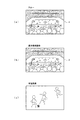
図5(a)は、特に図1(図3)のように表示部2を有する撮像装置1の場合において、表示部2にがスルー状態となっている場合(表示部2を介してユーザが視認する光景)を示しているとする。つまり、表示部2は単なる透明の板状体となっており、ユーザが視界光景を透明の表示部2を介して見ている状態である。
図5(b)は、モニタ表示状態として、撮像部3で撮像した画像が表示部2に表示された状態である。例えば図5(a)の状態で撮像部3,撮像信号処理部15,表示画像処理部12,表示駆動部13が動作し、これらの部位が撮像画像を通常に表示部2に表示した状態である。この場合の表示部2に表示される撮像画像(通常撮像画像)は、スルー状態の場合とほぼ同様となる。つまりユーザにとっては、通常の視界を、撮像された画像として見ている状態である。
FIG. 5A shows a case where the
FIG. 5B shows a state in which an image captured by the imaging unit 3 is displayed on the
図5(c)は、システムコントローラ10が撮像制御部11を介して撮像部3に望遠撮像を実行させた場合の撮像画像例である。例えばこのような望遠撮像としての画像撮像を行うことで、ユーザは図1の表示部2や図2の表示装置30において、望遠画像を見ることができる。またこのような画像をストレージ部25において記録したり、通信部26で外部機器に送信して外部機器側で保存することができる。
図示しないが、逆にシステムコントローラ10が撮像制御部11を介して撮像部3に広角撮像を実行させれば、近距離の光景が広角に映し出された画像が表示部2に表示されることになる。なお、望遠−広角の制御は、撮像部3におけるズームレンズの駆動制御の他、撮像信号処理部15での信号処理でも可能である。
FIG. 5C is an example of a captured image when the
Although not shown, conversely, if the
図6(a)は通常撮像画像を示し、図6(b)は拡大画像を示している。図6(a)のような光景を撮像している場合に、システムコントローラ10が、撮像制御部11を介して撮像信号処理部15に対して画像拡大処理を指示することで、図6(b)のような拡大撮像画像を得ることができる。
6A shows a normal captured image, and FIG. 6B shows an enlarged image. When a scene such as that shown in FIG. 6A is being imaged, the
図7(a)は通常撮像画像が示しているが、特に周囲が薄暗く、通常撮像画像は暗い画像となっている状態を示している。
このような場合に、システムコントローラ10は撮像制御部11(撮像部3,撮像信号処理部15)に対して撮像感度を上げることを指示したり、撮像信号処理における輝度レベル、コントラスト、シャープネス調整を指示することなどにより、図7(b)のように、よりはっきりした明るい撮像画像とすることができる。なお、照明部4に照明動作を実行させることも、このような撮像を行う場合に好適となる。
FIG. 7A shows a normal captured image. In particular, the periphery is dim and the normal captured image is a dark image.
In such a case, the
図8(a)は、例えばユーザが、子供が寝ている暗い寝室に居る場合の通常撮像画像を示している。この場合、暗い部屋の中であるため、通常撮像画像では、子供の姿等がはっきり現れない状況である。
このときにシステムコントローラ10が、撮像制御部11(撮像部3,撮像信号処理部15)に対して赤外線撮像感度の上昇を指示することで、図8(b)のように赤外線撮像画像が得られ、暗い部屋で子供の寝顔などを確認できる撮像画像となる。
FIG. 8A shows a normal captured image when the user is in a dark bedroom where a child is sleeping, for example. In this case, since it is in a dark room, the child's figure does not appear clearly in the normal captured image.
At this time, when the
図9(a)は通常撮像画像であるが、システムコントローラ10が、撮像制御部11(撮像部3,撮像信号処理部15)に対して紫外線撮像感度の上昇を指示することで、図9(b)のように紫外光成分を表した撮像画像が得られる。
FIG. 9A shows a normal captured image, but the
ここまで各種の撮像画像例を示したが、これらは一例にすぎない。本例においては、撮像部3,撮像信号処理部15の各処理や動作を制御することで、多様な撮像態様での撮像画像が実現される。
例えば、望遠撮像画像、広角撮像画像、望遠から広角までの間のズームインもしくはズームアウトを行いながらの撮像画像、拡大撮像画像、縮小撮像画像、フレームレートの可変撮像画像(高フレームレートでの撮像や低フレームレートでの撮像など)、高輝度撮像画像、低輝度撮像画像、コントラスト可変撮像画像、シャープネス可変撮像画像、撮像感度上昇状態の撮像画像、赤外線撮像感度上昇状態の撮像画像、紫外線撮像感度上昇状態の撮像画像、特定波長帯域をカットした撮像画像、モザイク画像/輝度反転画像/ソフトフォーカス/画像内の一部の強調表示/画像全体の色の雰囲気の可変などの画像エフェクトを加えた撮像画像、静止画撮像画像など、非常に多様な撮像画像態様が想定される。
Various examples of captured images have been shown so far, but these are only examples. In this example, by controlling each process and operation of the imaging unit 3 and the imaging
For example, a telephoto image, a wide-angle image, a captured image zoomed in or out from the telephoto to wide-angle, an enlarged image, a reduced image, a variable frame rate image (such as an image captured at a high frame rate) Low-frame-rate imaging, etc.), high-brightness captured image, low-brightness captured image, variable contrast captured image, sharpness variable captured image, captured image with increased imaging sensitivity, captured image with increased infrared imaging sensitivity, increased ultraviolet imaging sensitivity Captured image of the state, captured image with a specific wavelength band cut, captured image with added image effects such as mosaic image / inverted brightness image / soft focus / partial highlighting in image / variable color atmosphere of entire image A great variety of captured image modes such as a still image captured image are assumed.
[4.ユーザ状況の判定]
上述したように本例の撮像装置1(1A)は、使用者情報を取得するための構成として、視覚センサ19、加速度センサ20、ジャイロ21、生体センサ22を有する。
[4. Judgment of user status]
As described above, the imaging apparatus 1 (1A) of the present example includes the
視覚センサ19は、ユーザの視覚に関する情報を検出するものとするが、この視覚センサ19は、一例としては、例えば図1の撮像装置1において表示部2の近辺に配置されてユーザの眼部を撮像するようにされた撮像部により形成できる。そして該撮像部が撮像したユーザの眼部の画像をシステムコントローラ10が取り込み、ユーザ状況判定機能10aが画像解析を行うことで、視線方向、焦点距離、瞳孔の開き具合、眼底パターン、まぶたの開閉などを検出でき、これた基づいてユーザの状況や意志を判定できる。
或いは視覚センサ19は、表示部2の近辺に配置されてユーザの眼部に光を照射する発光部と、眼部からの反射光を受光する受光部により形成できる。例えば受光信号からユーザの水晶体の厚みを検知することでユーザの眼の焦点距離を検出することも可能である。
The
Alternatively, the
ユーザの視線方向を検出することで、システムコントローラ10は例えば表示部2に表示された画像においてユーザが注目している部分を判定できる。
またシステムコントローラ10は、ユーザの視線方向を、操作入力として認識することも可能である。例えばユーザが視線を左右に動かすことを、撮像装置1に要求する所定の操作入力とするなどである。
ユーザの焦点距離を検出することで、ユーザが注目している光景が遠方か近傍かを判別でき、それに応じてズーム制御、拡大/縮小制御などを行うことも可能である。例えばユーザが遠くを見たときに望遠撮像を行うなどである。
ユーザの瞳孔の開き具合を検出すれば、スルー状態であれば周囲の明るさの状態、またモニタ表示状態であれば表示している画像に対してユーザが感じているまぶしさ等を判定でき、それに応じて輝度調整、撮像感度調整などを行うことができる。
ユーザの眼底パターンの検出は、例えばユーザの個人認証に用いることができる。眼底パターンは各人に固有のパターンであるため、眼底パターンによって装着したユーザを判定し、そのユーザに適した制御を行うこと、或いは特定のユーザの場合にのみ撮像動作を実行できるようにすることなどの制御が可能である。
ユーザのまぶたの開閉動作を検出することで、ユーザが感じているまぶしさや眼の疲れを判定できる。また、まぶたの開閉を、ユーザの意識的な操作入力として認識することも可能である。例えばユーザが3回まばたきをすることを、所定の操作入力と判定するなどである。
By detecting the direction of the user's line of sight, the
The
By detecting the focal length of the user, it is possible to determine whether the scene that the user is paying attention to is far or near, and it is also possible to perform zoom control, enlargement / reduction control, and the like accordingly. For example, telephoto imaging is performed when the user looks far away.
By detecting the degree of pupil opening of the user, it is possible to determine the brightness of the surroundings if it is a through state, the glare that the user feels for the displayed image if it is a monitor display state, Accordingly, brightness adjustment, imaging sensitivity adjustment, and the like can be performed.
The detection of the fundus pattern of the user can be used for personal authentication of the user, for example. Since the fundus pattern is unique to each person, it is possible to determine the user wearing the fundus pattern and perform control suitable for the user, or to perform an imaging operation only for a specific user. Such control is possible.
By detecting the opening / closing operation of the user's eyelids, it is possible to determine the user's feeling of glare or eye fatigue. It is also possible to recognize opening / closing of the eyelid as a user's conscious operation input. For example, it is determined that the user blinks three times as a predetermined operation input.
加速度センサ20、及びジャイロ21は、ユーザの動きに応じた信号を出力する。例えば加速度センサ20は直線方向の動きを検出し、ジャイロ21により回転系の動きや振動を検出する場合に適している。
加速度センサ20やジャイロ21の配置位置にもよるが、加速度センサ20やジャイロ21によって、ユーザの身体全体もしくは身体の各部の動きを検知できる。
例えば図1のような眼鏡型の撮像装置1の内部に取り付けられた場合、つまり加速度センサ20及びジャイロ21がユーザの頭部の動きを検出するものとされた場合は、加速度センサ20の情報は、ユーザの頭部或いは全身の動きとしての加速度情報となり、またジャイロ21はユーザの頭部或いは全身の動きとしての角速度や振動の情報となる。
これによって、ユーザが首から頭部を動かす挙動を検知できる。例えば上方を向いている状態や下方を向いている状態を判定できる。下方を向いているときとは、ユーザが読書など近傍を見ていると判断することも可能である。逆に上方を向いているときは、遠方を見ていると判断することもできる。
またシステムコントローラ10はユーザの首から頭部を動かす挙動を検出したら、それをユーザの意識的な操作と認識することもできる。例えば左に2回首を振ったら、それが所定の操作入力とするなどである。
また加速度センサ20及びジャイロ21によっては、ユーザが静止状態(非歩行状態)であるか、歩行状態であるか、走行状態であるかなどの判断も可能である。また立っている状態から座った場合、或いは立ち上がった場合などの検出も可能である。
また、加速度センサ20やジャイロ21が、頭部に装着する装着ユニットとは別体に設けられ、腕や足に取り付けられるようにすれば、腕のみの挙動、足のみの挙動も検知できる。
The
Although depending on the arrangement positions of the
For example, when it is attached inside the eyeglass-
Thereby, it is possible to detect the behavior of the user moving the head from the neck. For example, it is possible to determine a state facing upward or a state facing downward. When facing down, it can be determined that the user is looking in the vicinity, such as reading. Conversely, when looking upward, it can be determined that the user is looking far away.
Further, when the
Further, depending on the
Further, if the
生体センサ22は、ユーザの生体情報として例えば心拍情報(心拍数)、脈拍情報(脈拍数)、発汗情報、脳波情報(例えばα波、β波、θ波、δ波の情報)、又は皮膚電気反応、体温、血圧、呼吸活動(例えば呼吸の速さ、深さ、換気量など)等を検出するが、これらの情報からシステムコントローラ10は、ユーザが緊張状態や興奮状態にあること、或いは感情的に穏やかな状態にあること、或いは快適な状態か不快な状態にあることなどを判定できる。
また撮像装置1をユーザが装着したことの検知も、生体情報により可能である。例えばシステムコントローラ10は、ユーザが撮像装置1を装着していない時には生体情報検知のみをおこなうスタンバイ状態に制御し、生体情報によりユーザが撮像装置1を装着したことを検知したら、電源オン状態とすることや、逆にユーザが撮像装置1の装着を外したらスタンバイ状態に戻すなどの制御も可能である。
さらに生体センサ22による検出情報は、ユーザの個人認証(装着者個人の識別)にも利用できる。
なお生体センサ22は、例えば眼鏡型の撮像装置1の装着フレーム内側に配置することで、例えばユーザの側頭部や後頭部において、上記情報を検知できるようにしてもよいし、撮像装置1(又は1A)の装着フレーム部分とは別体として、身体の所定箇所に装着されるようにしてもよい。
The
In addition, it is possible to detect that the user wears the
Furthermore, the detection information by the
The
[5.各種動作例]
本実施の形態の撮像装置1(1A)は、以上のように視覚センサ19、加速度センサ20、ジャイロ21、生体センサ22から検出されるユーザの情報に応じて、システムコントローラ10が撮像動作を制御することで、ユーザの意志や状況に応じた適切な撮像を実現するものである。
このためのシステムコントローラ10の制御に基づく各種動作例を説明していく。
[5. Examples of various operations]
In the imaging apparatus 1 (1A) of the present embodiment, the
Various operation examples based on the control of the
なお、撮像装置1(1A)においては、電源オン状態において撮像処理系(撮像部13,撮像信号処理部15、撮像制御部11)は常時撮像動作を行うようにしても良いし、電源オン状態において撮像開始のトリガが発生した場合に撮像を開始するようにしてもよい。
つまり電源オン制御と撮像開始制御は同時でも良いし、別のタイミングでもよい。
例えば上述したようにユーザが撮像装置1を装着したことを検知して、システムコントローラ10が電源オンとする処理を行うものとする場合には、電源オンとなった後、所定の撮像開始トリガによって撮像を開始させる例が考えられる。
また、例えばシステムコントローラ10は、所定の撮像開始トリガを検知することによって装置の電源をオンとすると共に撮像を開始させる例も考えられる。
In the imaging apparatus 1 (1A), the imaging processing system (the
That is, the power-on control and the imaging start control may be performed simultaneously or at different timings.
For example, when it is detected that the user has attached the
For example, the
まず図10,図11,図12で、システムコントローラ10の動作制御機能10bとしての制御処理例を示す。
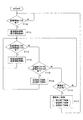
図10は、撮像動作の実行中は、モニタ表示動作、ストレージ部25での記録動作、通信部26からの送信動作の一部又は全部を同時的に行う例である。
なお、ここで述べるモニタ表示動作とは、図1の撮像装置1の場合は、表示部2に撮像画像を表示させる動作であり、図2の撮像装置1Aの場合は、通信部26から表示装置30に撮像画像データを送信し、表示装置30においてモニタ表示を実行できる状態とする動作である。
またここで述べる通信部26からの送信動作とは、表示装置30に限らず、上述したように想定される多様な外部機器に対して、撮像信号としての画像データ及び音声データを送信する動作である。送信先の機器で画像データ及び音声データがどのように処理されるか(例えば表示/音声出力されるか、記録されるか、さらに他の機器に転送・配信されるかなど)は送信先の機器によるものとなる。
First, FIG. 10, FIG. 11 and FIG. 12 show control processing examples as the
FIG. 10 illustrates an example in which a part or all of the monitor display operation, the recording operation in the
The monitor display operation described here is an operation for displaying a captured image on the
The transmission operation from the
図10のステップF101では、システムコントローラ10は撮像開始トリガが発生したか否かを確認している。ここでは撮像開始トリガの発生とは、ユーザ状況判定機能10aによって判定されたユーザの意志又は状況により、撮像動作を開始させるとシステムコントローラ10自身が判断することを意味している。ユーザの意識的な動作、又はユーザの無意識な動作、或いはユーザの状態(ユーザの身体状況やユーザ個人の認識など)によって、システムコントローラ10は撮像開始トリガの有無を判断する。具体例は後述する。
In step F101 of FIG. 10, the
撮像開始トリガがあったと判別した場合は、システムコントローラ10は処理をステップF102に進め、撮像開始制御を行う。即ち撮像制御部11に撮像開始を指示して撮像部3及び撮像信号処理部15の通常撮像動作を実行させる。
またこのときシステムコントローラ10は表示開始制御、記録開始制御、送信開始制御の一部又は全部を実行する。
表示開始制御とは、図1、図3の撮像装置1の場合、表示制御部14に指示して、表示画像処理部12及び表示駆動部13に、撮像信号を通常撮像画像の態様で表示部2に表示させる動作を実行させることになる。また図2,図4の撮像装置1Aの場合、通信部26から外部の表示装置30に対して撮像された画像データ及び音声データを送信する動作を実行させる制御となる。
記録開始制御とは、撮像された画像データ及び音声データの記録をストレージ部25に開始させる制御となる。
送信開始制御とは、撮像された画像データ及び音声データの外部機器に対する送信を通信部26に開始させる制御となる。
If it is determined that there has been an imaging start trigger, the
At this time, the
In the case of the
The recording start control is control for causing the
The transmission start control is control for causing the
撮像を開始させた後は、システムコントローラ10は、ステップF103で撮像動作制御トリガが発生したか否かを監視し、またステップF104で撮像終了トリガが発生したか否かを監視する。
撮像動作制御トリガの発生とは、ユーザ状況判定機能10aによって判定されたユーザの意志又は状況により、撮像動作態様の変更を行うとシステムコントローラ10自身が判断することを意味している。また撮像終了トリガの発生とは、ユーザ状況判定機能10aによって判定されたユーザの意志又は状況により、撮像動作を終了するとシステムコントローラ10自身が判断することを意味している。ユーザの意識的な動作、又はユーザの無意識な動作や状態(ユーザの身体状況やユーザ個人の認識など)によって、システムコントローラ10は撮像終了トリガの有無を判断する。これらについても具体例は後述する。
After starting the imaging, the
The occurrence of the imaging operation control trigger means that the
撮像動作制御トリガの発生と判断した場合は、システムコントローラ10は処理をステップF103からF105に進め、撮像動作に関しての制御を行う。つまり撮像制御部11に指示し、その時点のユーザの意志又は状況に応じた態様の撮像動作を実行させる。
ステップF105で撮像動作態様に関しての制御を行った後も、ステップF103,F104でトリガ発生の監視を行う。
If it is determined that an imaging operation control trigger has occurred, the
Even after the control relating to the imaging operation mode is performed in step F105, the trigger generation is monitored in steps F103 and F104.
撮像終了トリガの発生と判断した場合は、システムコントローラ10は処理をステップF104からF106に進め、撮像終了制御を行う。即ち撮像制御部11に撮像終了を指示して撮像部3及び撮像信号処理部15の撮像動作を終了させる。
またこのときシステムコントローラ10は表示終了制御、記録終了制御、送信終了制御の一部又は全部を実行する。
即ちステップF102でモニタ表示を開始させていた場合は、その開始させた動作を終了させる。また記録動作を開始させていた場合は、ストレージ部25における記録動作を終了させる。また送信動作を開始させていた場合は、通信部26における送信動作を終了させる。
そしてシステムコントローラ10はステップF101に戻る。
If it is determined that an imaging end trigger has occurred, the
At this time, the
That is, when the monitor display has been started in step F102, the started operation is ended. If the recording operation has been started, the recording operation in the
Then, the
次に図11は、撮像動作の実行タイミングとは別に、ストレージ部25での記録動作、通信部26からの送信動作の実行タイミングを制御する例である。なお、撮像開始制御、撮像終了制御、表示開始制御、表示終了制御、記録開始制御、記録終了制御、送信開始制御、送信終了制御の各制御の内容は図10と同様である。
Next, FIG. 11 is an example of controlling the execution timing of the recording operation in the
図11のステップF110では、システムコントローラ10は撮像開始トリガが発生したか否かを確認している。
撮像開始トリガがあったと判別した場合は、システムコントローラ10は処理をステップF111に進め、撮像開始制御を行う。またこのときシステムコントローラ10は表示開始制御を行う。
In step F110 of FIG. 11, the
If it is determined that there has been an imaging start trigger, the
撮像を開始させた後は、システムコントローラ10は、ステップF112で記録開始トリガ(又は送信開始トリガ)が発生したか否かを監視し、またステップF113では記録終了トリガ(又は送信終了トリガ)が発生したか否かを監視し、またステップF114で撮像終了トリガが発生したか否かを監視する。
記録開始トリガの発生とは、ユーザ状況判定機能10aによって判定されたユーザの意志又は状況により、ストレージ部25での記録動作を開始するとシステムコントローラ10自身が判断することを意味している。
また記録終了トリガの発生とは、ユーザ状況判定機能10aによって判定されたユーザの意志又は状況により、ストレージ部25での記録動作を終了するとシステムコントローラ10自身が判断することを意味している。
送信開始トリガの発生とは、ユーザ状況判定機能10aによって判定されたユーザの意志又は状況により、通信部26からの送信動作を開始するとシステムコントローラ10自身が判断することを意味している。
送信終了トリガの発生とは、ユーザ状況判定機能10aによって判定されたユーザの意志又は状況により、通信部26からの送信動作を終了するとシステムコントローラ10自身が判断することを意味している。
なお、例えば図2,図4の撮像装置1Aの場合、ステップF111で表示開始制御を行うことが、通信部26からの表示装置30への送信開始の制御を行うことに相当するため、送信開始トリガ、送信終了トリガの発生とは図1,図3の撮像装置1を想定した場合の処理となる。但し、図2,図4の撮像装置1Aであっても、モニタリング用の表示装置30以外の他の外部機器に送信することを想定すれば、送信開始トリガ、送信終了トリガは、そのような送信についての送信制御のトリガと考えることができる。
After starting imaging, the
The occurrence of the recording start trigger means that the
Further, the occurrence of the recording end trigger means that the
The occurrence of the transmission start trigger means that the
The occurrence of the transmission end trigger means that the
For example, in the case of the
記録開始トリガの発生と判断した場合は、システムコントローラ10は処理をステップF112からF115に進め、ストレージ部25に撮像による画像データ及び音声データの記録を開始させる制御を行う。
また送信開始トリガの発生と判断した場合も、システムコントローラ10は処理をステップF112からF115に進め、通信部26から外部機器に対して、撮像による画像データ及び音声データの送信を開始させる制御を行う。
記録開始制御又は送信開始制御を行ったら、システムコントローラ10はステップF112,F113,F114のトリガ監視ループに戻る。
If it is determined that a recording start trigger has occurred, the
Even when it is determined that a transmission start trigger has occurred, the
When the recording start control or the transmission start control is performed, the
記録終了トリガの発生と判断した場合は、システムコントローラ10は処理をステップF113からF116に進め、ストレージ部25における記録動作を終了させる制御を行う。
また送信終了トリガの発生と判断した場合も、システムコントローラ10は処理をステップF113からF116に進め、通信部26から外部機器に対する、撮像による画像データ及び音声データの送信を終了させる制御を行う。
記録終了制御又は送信終了制御を行ったら、システムコントローラ10はステップF112,F113,F114のトリガ監視ループに戻る。
If it is determined that a recording end trigger has occurred, the
Also, when it is determined that a transmission end trigger has occurred, the
When the recording end control or the transmission end control is performed, the
撮像終了トリガの発生と判断した場合は、システムコントローラ10は処理をステップF114からF117に進め、撮像終了制御を行う。即ち撮像制御部11に撮像終了を指示して撮像部3及び撮像信号処理部15の撮像動作を終了させる。またこのときシステムコントローラ10は表示終了制御を実行する。
なお、撮像終了トリガが発生した時点で、記録動作や送信動作が終了されていない場合は、このときに記録終了制御や送信終了制御も行うことになる。
そしてシステムコントローラ10はステップF110に戻る。
If it is determined that an imaging end trigger has occurred, the
If the recording operation or the transmission operation is not completed when the imaging end trigger is generated, the recording end control and the transmission end control are also performed at this time.
Then, the
次に図12は、撮像動作の実行タイミングとは別に、ストレージ部25での記録動作、通信部26からの送信動作の実行タイミングを制御し、さらに撮像動作態様の制御も行う例である。なお、撮像開始制御、撮像終了制御、表示開始制御、表示終了制御、記録開始制御、記録終了制御、送信開始制御、送信終了制御の各制御の内容は図10、図11と同様である。
Next, FIG. 12 is an example in which the recording operation in the
図12のステップF120では、システムコントローラ10は撮像開始トリガが発生したか否かを確認している。
撮像開始トリガがあったと判別した場合は、システムコントローラ10は処理をステップF121に進め、撮像開始制御を行う。またこのときシステムコントローラ10は表示開始制御を行う。
In step F120 of FIG. 12, the
If it is determined that there has been an imaging start trigger, the
撮像を開始させた後は、システムコントローラ10は、ステップF122で記録開始トリガ(又は送信開始トリガ)が発生したか否かを監視し、またステップF123では記録終了トリガ(又は送信終了トリガ)が発生したか否かを監視し、またステップF124で撮像動作制御トリガが発生したか否かを監視し、またステップF125で撮像終了トリガが発生したか否かを監視する。
After starting imaging, the
記録開始トリガの発生と判断した場合は、システムコントローラ10は処理をステップF122からF126に進め、ストレージ部25に撮像による画像データ及び音声データの記録を開始させる制御を行う。
また送信開始トリガの発生と判断した場合も、システムコントローラ10は処理をステップF122からF126に進め、通信部26から外部機器に対して、撮像による画像データ及び音声データの送信を開始させる制御を行う。
記録開始制御又は送信開始制御を行ったら、システムコントローラ10はステップF122,F123,F124,F125のトリガ監視ループに戻る。
If it is determined that a recording start trigger has occurred, the
Even when it is determined that a transmission start trigger has occurred, the
After performing the recording start control or the transmission start control, the
記録終了トリガの発生と判断した場合は、システムコントローラ10は処理をステップF123からF127に進め、ストレージ部25における記録動作を終了させる制御を行う。
また送信終了トリガの発生と判断した場合も、システムコントローラ10は処理をステップF123からF127に進め、通信部26から外部機器に対する、撮像による画像データ及び音声データの送信を終了させる制御を行う。
記録終了制御又は送信終了制御を行ったら、システムコントローラ10はステップF122,F123,F124,F125のトリガ監視ループに戻る。
If it is determined that a recording end trigger has occurred, the
Even when it is determined that a transmission end trigger has occurred, the
When the recording end control or the transmission end control is performed, the
撮像動作制御トリガの発生と判断した場合は、システムコントローラ10は処理をステップF124からF128に進め、撮像動作に関しての制御を行う。つまり撮像制御部11に指示し、その時点のユーザの意志又は状況に応じた態様の撮像動作を実行させる。
ステップF128で撮像動作態様に関しての制御を行った後も、システムコントローラ10はステップF122,F123,F124,F125のトリガ監視ループに戻る。
If it is determined that an imaging operation control trigger has occurred, the
Even after controlling the imaging operation mode in step F128, the
撮像終了トリガの発生と判断した場合は、システムコントローラ10は処理をステップF125からF129に進め、撮像終了制御を行う。即ち撮像制御部11に撮像終了を指示して撮像部3及び撮像信号処理部15の撮像動作を終了させる。またこのときシステムコントローラ10は表示終了制御を実行する。
なお、撮像終了トリガが発生した時点で、記録動作や送信動作が終了されていない場合は、このときに記録終了制御や送信終了制御も行うことになる。
そしてシステムコントローラ10はステップF120に戻る。
If it is determined that an imaging end trigger has occurred, the
If the recording operation or the transmission operation is not completed when the imaging end trigger is generated, the recording end control and the transmission end control are also performed at this time.
Then, the
システムコントローラ10は動作制御機能10bにより例えば以上の図10又は図11又は図12の処理を行って撮像開始/終了や撮像動作態様の切換制御、さらには記録動作や送信動作の開始/終了制御を行う。
なお、ここでは撮像開始/終了制御と表示開始/終了制御を同じタイミングで実行するものとして説明したが、例えば図1,図3のように表示部3がユーザの両眼の直前に配置される構成の場合、撮像を行っている期間にモニタ表示を行わないようにする場合もある。例えばユーザの意志や状況に応じて、表示部2をスルー状態に切り換える制御も考えられる。例えば図11、図12の処理例では、撮像動作と、記録動作又は送信動作を別のタイミングで実行制御しているが、この記録動作又は送信動作のように、モニタ表示開始トリガ、モニタ表示終了トリガの判断を行うものとしてモニタ表示動作の実行制御を行うようにしてもよい。
The
Here, the imaging start / end control and the display start / end control are described as being executed at the same timing. However, for example, the display unit 3 is arranged immediately in front of the user's eyes as shown in FIGS. In the case of the configuration, there is a case where the monitor display is not performed during the imaging period. For example, a control for switching the
そしてこれら図10,図11,図12の処理においては、撮像開始トリガ、撮像動作制御トリガ、撮像終了トリガ、記録開始トリガ、記録終了トリガ、送信開始トリガ、送信終了トリガの判断に基づく制御を行っているが、これらのトリガ判断と制御内容の具体例について図13以降で説明していく。 10, 11, and 12, control based on the determination of the imaging start trigger, the imaging operation control trigger, the imaging end trigger, the recording start trigger, the recording end trigger, the transmission start trigger, and the transmission end trigger is performed. However, specific examples of trigger determination and control contents will be described with reference to FIG.
図13から図20は、システムコントローラ10のユーザ状況判定機能10aとしての処理例を示しており、これらは動作制御機能10bによる上記図10又は図11又は図12の処理と並列的に実行されているとする。なお並列的な処理とは、例えばシステムコントローラ10が図10の処理を実行している期間中に、図13〜図20のような検知処理が定期的に割込処理としてに行われればよいものである。これら図13〜図20のような処理のプログラムは、図10又は図11又は図12の処理を実行するプログラムに組み込まれていても良いし、定期的に呼び出される別のプログラムとされても良い。つまりプログラムの形態が限定されるものではない。
13 to 20 show processing examples as the user situation determination function 10a of the
まず図13,図14で、撮像開始トリガの判断についての例を述べる。
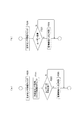
図13(a)(b)は、ユーザの挙動を撮像開始トリガとして検知する例である。
図13(a)のステップF200では、システムコントローラ10が加速度センサ20、又はジャイロ21からの検出情報(加速度信号、角速度信号)を監視する処理を示している。
例えば首を縦に2回振る、左右に1往復振る、首を1周回す・・など、特定の動作を、ユーザが撮像開始を求める操作であると設定されているとする。システムコントローラ10は、加速度センサ20又はジャイロ21(又はその両方)からの検出情報により、そのような撮像開始の意志を示す特定の動作に相当する動作があったと判別した場合は、処理をステップF201からF202に進め、撮像開始トリガ発生と判別する。
First, an example of determination of an imaging start trigger will be described with reference to FIGS.
FIGS. 13A and 13B are examples in which the user's behavior is detected as an imaging start trigger.
Step F200 in FIG. 13A shows a process in which the
For example, it is assumed that a specific operation such as shaking the neck twice in the vertical direction, swinging once in the right and left directions, and turning the neck once, is an operation for the user to start imaging. If the
このようにステップF202で撮像開始トリガ発生と判別することにより、例えば上記図10の処理はステップF101からF102に進むことになり(図11の処理の場合はステップF110からF111に進み、図12の処理の場合はステップF120からF121に進む)、システムコントローラ10は撮像制御部11に撮像開始を指示することになる。
なお加速度センサ20又はジャイロ21からの情報で検出する、モニタ表示を求める操作となるユーザの特定の挙動としては、例えばジャンプする、手を振る、腕をゆらす、足をゆらすなど、他にも各種考えられる。
In this way, by determining that the imaging start trigger is generated in step F202, for example, the process in FIG. 10 proceeds from step F101 to F102 (in the case of the process in FIG. 11, the process proceeds from step F110 to F111, and FIG. In the case of processing, the process proceeds from step F120 to F121), and the
The user's specific behavior that is detected by the information from the
図13(b)は、視覚センサ19の情報に基づいて撮像開始トリガを判別する例である。
システムコントローラ10はステップF210で、視覚センサ19からの情報を解析する。例えば視覚センサ19としてユーザの眼部を撮像する撮像部が設けられている場合、その撮像画像を解析する。
例えばまばたきを3回連続して行うという特定の動作を、ユーザが撮像開始を求める操作であると設定されているとすると、システムコントローラ10は、画像解析によりこの挙動を監視することになる。
そしてシステムコントローラ10は、ユーザがまばたきを3回連続して行ったことを検知したら、処理をステップF211からF212に進め、撮像開始トリガ発生と判別する。
ステップF212で撮像開始トリガ発生と判別することにより、上記図10のステップF103(又は図11のステップF111、又は図12のステップF121)で、システムコントローラ10は撮像制御部11に撮像開始を指示することになる。
なお視覚センサ19からの情報で検出する、モニタ表示を求める操作となるユーザの特定の挙動としては、例えば眼球を回す、眼球を左右又は上下に2往復させるなど、他にも各種考えられる。
FIG. 13B is an example of determining an imaging start trigger based on information from the
In step F210, the
For example, if it is set that the specific operation of performing blinking three times in succession is an operation for the user to start imaging, the
When the
By determining that an imaging start trigger has occurred in step F212, the
In addition, as the specific behavior of the user, which is detected by information from the
図14(a)は、ユーザの無意識の挙動や身体状況により撮像開始トリガを判別する例である。
システムコントローラ10はステップF220で、生体センサ22からの脳波、心拍数、発汗量、血圧などの情報をチェックする。
またステップF221では、システムコントローラ10は加速度センサ20、又はジャイロ21からの検出情報(加速度信号、角速度信号)を監視する処理を示している。
そしてステップF222でシステムコントローラ10は、生体センサ22からの情報や、ユーザの挙動に基づいて、ユーザが平静状態であるか、或いは平静ではない状態、例えば緊張又は興奮したり、何らかの事象に注意や興味を向けたりしたような状態にあるかを判断する。例えば発汗状況、心拍数、脈拍、脳波、血圧等の検出値の変化や、急に首を別の方向に向けたり、走り出す、ジャンプするなどの突発的な挙動による、加速度や振動としての検出値の変化により、平静状態からの変化を判別する。
システムコントローラ10はユーザが平静状態でなくなったと判別した場合は、処理をステップF222からF223に進め、撮像開始トリガ発生と判別する。
このようにステップF223で撮像開始トリガ発生と判別することにより、上記図10のステップF103(又は図11のステップF111、又は図12のステップF121)で、システムコントローラ10は撮像制御部11に撮像開始を指示することになる。
この場合、ユーザが通常とは異なる心理状況や身体状況となった場合に、自動的に撮像が開始されるものとなる。
FIG. 14A is an example in which the imaging start trigger is determined based on the user's unconscious behavior and physical condition.
In step F220, the
In step F221, the
In step F222, based on information from the
If the
In this way, by determining that the imaging start trigger is generated in step F223, the
In this case, imaging is automatically started when the user has an unusual psychological situation or physical situation.
なお、ユーザの無意識的な挙動や身体状況によって撮像開始トリガを判別する処理として他にも各種想定される。
例えば視覚センサ19からの情報で、ユーザの視線が急に動いた場合に撮像開始トリガ発生と判断するなど、視覚センサ19の情報を用いたり、また音声入力部6からの入力音声に基づいて撮像開始トリガ発生を判断することも考えられる。
Various other processes are conceivable for determining the imaging start trigger based on the user's unconscious behavior and physical condition.
For example, the information from the
図14(b)は、ユーザが撮像装置1(1A)を装着すること自体を、撮像開始のトリガとする例である。
システムコントローラ10はステップF230で、生体センサ22からの脳波、心拍数、皮膚電気反応などの情報をチェックする。
そしてステップF231でシステムコントローラ10は、生体センサ22からの情報に基づいて、ユーザが撮像装置1(1A)を装着したか否かを判断する。生体センサ22により人体からの情報が得られる状態になったか否かによりユーザの装着を検知できる。
システムコントローラ10はユーザが撮像装置1(1A)を装着したと判別した場合は、処理をステップF231からF232に進め、撮像開始トリガ発生と判別する。
このようにステップF232で撮像開始トリガ発生と判別することにより、上記図10のステップF103(又は図11のステップF111、又は図12のステップF121)で、システムコントローラ10は撮像制御部11に撮像開始を指示することになる。
このように例えば生体センサ22の反応により、ユーザによる装着を検出できるため、生体センサ22による生体反応として、例えば脈拍、脳波、皮膚反応等の検出が開始されたことを撮像開始トリガ発生とする。これにより、ユーザが装着している期間に撮像を行うという動作制御を実行できる。
FIG. 14B is an example in which the user itself wears the imaging device 1 (1A) as a trigger for starting imaging.
In step F230, the
In step F231, the
If the
In this manner, by determining that the imaging start trigger is generated in step F232, the
Thus, for example, since the user's wearing can be detected by the reaction of the
なお、不特定のユーザの装着ではなく、特定のユーザが装着したら、撮像を開始するという制御ことも考えられる。上述のように視覚センサ19で検出する眼底パターンや生体センサ22による検出信号によっては、ユーザの個人を識別できる。例えば予め使用するユーザについて眼底パターンや生体情報を登録しておくことで、システムコントローラ10は、特定のユーザが装着しているか否かを判別することが可能である。
従って、システムコントローラ10は、撮像装置1が或るユーザに装着された際に個人認証を行い、特定のユーザを認識した場合に、それを撮像開始トリガと判別し、撮像開始制御を行うこともできる。
Note that it is also conceivable to start imaging when a specific user wears instead of wearing an unspecified user. As described above, the individual of the user can be identified by the fundus pattern detected by the
Accordingly, the
なお、以上の図13,図14では、撮像開始トリガの発生判断の例について述べたが、図11,図12の処理例における記録開始トリガや送信開始トリガの発生判断も、これら図13,図14の例のように、ユーザの意識的な挙動、無意識の挙動、身体状況、個人認証などに基づいて行えばよい。 In FIGS. 13 and 14, the example of determining the occurrence of the imaging start trigger has been described. However, the generation determination of the recording start trigger and the transmission start trigger in the processing examples of FIGS. As in the example of FIG. 14, it may be performed based on the user's conscious behavior, unconscious behavior, physical condition, personal authentication, and the like.
次に、図10のステップF103や図12のステップF124としての、撮像動作制御トリガ発生の判断に関する処理例を図15から図18で説明する。
図15(a)は、ユーザの視線の動きによりズーム制御を行う例である。
システムコントローラ10は図15(a)のステップF300で、視覚センサ19からの情報を解析する。例えば視覚センサ19としてユーザの眼部を撮像する撮像部が設けられている場合、その撮像画像を解析する。
ここで、システムコントローラ10は、ユーザの視線方向が下方に移動したことを検知したら、ステップF301からF302に進め、ズームアップ(広角ズーム)撮像への切換の撮像動作制御トリガの発生と判別する。
ステップF302で広角ズームの撮像動作制御トリガ発生と判別することにより、上記図10の処理はステップF103からF105に進むことになり(図12の処理の場合はステップF124からF128に進む)、システムコントローラ10は撮像制御部11にズームアップ動作を指示する。
ユーザの視線が下方に向くときは、新聞や書籍を読んだり、目の前の非常に近い位置を見ようとしているときであるため、このようにズームアップ撮像が行われることで、ユーザの近傍をはっきり示す撮像画像が得られることになる。
Next, processing examples relating to the determination of the occurrence of the imaging operation control trigger as step F103 in FIG. 10 and step F124 in FIG. 12 will be described with reference to FIGS.
FIG. 15A is an example in which zoom control is performed by the movement of the user's line of sight.
The
When the
When it is determined in step F302 that an imaging operation control trigger for wide-angle zoom has occurred, the process in FIG. 10 proceeds from step F103 to F105 (in the case of the process in FIG. 12, the process proceeds from step F124 to F128). 10 instructs the
When the user's line of sight faces downward, it is when reading a newspaper or book or looking at a very close position in front of his eyes. A clearly shown captured image is obtained.
図15(b)はユーザの首(頭部)の動きと眼の焦点距離に基づいて、ズーム制御を行う例である。
システムコントローラ10は図15(b)のステップF310で、視覚センサ19からの情報を解析し、ユーザの眼の焦点距離や視線方向を検出する。またステップF311でシステムコントローラ10は加速度センサ20、ジャイロ21からの検出情報(加速度信号、角速度信号)を監視し、ユーザの首の動きを判別する。
そしてシステムコントローラ10はステップF312,F313で、焦点距離及び首の向きの検出結果から、ユーザが近傍を見る状態にあるか、遠方を見る状態にあるかを判別する。
FIG. 15B is an example in which zoom control is performed based on the movement of the user's neck (head) and the focal length of the eyes.
In step F310 of FIG. 15B, the
In steps F312 and F313, the
システムコントローラ10は、ユーザが近傍を見ていると判別したらステップF312からF314に進んで、ズームアップ(広角ズーム)表示への撮像動作制御トリガの発生と判別する。そしてステップF316で、その際の焦点距離とユーザの首(頭部)の向きから適切なズーム倍率を算出する。
またシステムコントローラ10は、ユーザが遠方を見ていると判別したらステップF313からF315に進んで、望遠ズーム表示への撮像動作制御トリガの発生と判別する。そしてステップF316で、その際の焦点距離とユーザの首(頭部)の向きから適切なズーム倍率を算出する。
このステップF314,F316、もしくはステップF315、F316の処理が行われることで、システムコントローラ10の図10の処理はステップF104からF106(図12の処理の場合はステップF124からF128)に進むことになり、撮像制御部11に計算した倍率でのズーム動作を指示する。
これによりユーザが見ようとしている光景に応じてズームアップ画像や、例えば図5(c)のような望遠画像が撮像されることになる。
If the
If the
The processing in FIG. 10 of the
As a result, a zoomed-in image or a telephoto image such as that shown in FIG. 5C is picked up according to the scene that the user wants to see.
なお、図15(a)(b)では撮像部13のズーム動作により撮像画像を変化させる例を述べたが、視線方向、焦点距離、首の向きなどに応じて、撮像信号処理部15に画像拡大/縮小処理などを実行させるようにしてもよい。
In FIGS. 15A and 15B, the example in which the captured image is changed by the zoom operation of the
図16は、ユーザにとって快適な画像の撮像や、周囲が暗い状況に対応できるようにする例である。例えば図1,図3の撮像装置1によりユーザが眼前の表示部2で撮像画像をモニタリングしているような状況において特に好適である。
FIG. 16 is an example in which it is possible to capture an image comfortable for the user and to cope with a dark environment. For example, it is particularly suitable in a situation where the user is monitoring a captured image on the
システムコントローラ10は図16のステップF400で、視覚センサ19からの情報を解析し、ユーザの眼の瞳孔の開き具合やまばたきの状況(単位時間あたりのまばたき回数など)を検出する。
またステップF401で、生体センサ22からの脳波、心拍数、発汗量、血圧などの情報をチェックする。
システムコントローラ10は、これらの視覚センサ19や生体センサ22からの情報に基づいて、表示部2でモニタ表示されている撮像画像に対してユーザが快適な状態であるか不快な状態であるか否かを判断する。
そしてシステムコントローラ10は、ユーザの画像感知状況が快適ではないと判断した場合は、処理をステップF402からF403に進め、撮像画像の調整制御の撮像動作制御トリガ発生と判別する。
その場合ステップF404で、ユーザの状況に応じて快適と考えられる調整値、例えば撮像感度、輝度レベル、コントラスト、シャープネス、照明の明るさなどの調整値を算出する。
In step F400 of FIG. 16, the
In step F401, information such as an electroencephalogram, a heart rate, a sweat rate, and a blood pressure from the
The
If the
In that case, in step F404, adjustment values that are considered comfortable according to the user's situation, for example, adjustment values such as imaging sensitivity, luminance level, contrast, sharpness, and brightness of illumination are calculated.
このステップF403,F404の処理により、システムコントローラ10の図10の処理はステップF103からF105(図12の処理の場合はステップF124からF128)に進むことになり、この場合は撮像部13の撮像感度の調整や、撮像信号処理部15に対する輝度調整、コントラスト調整、シャープネス調整などの処理を指示する。この処理により、撮像画像の画質が調整され、ユーザにとって快適な撮像及びモニタリング表示画像を得ることができる。例えば図7(b)のような撮像画像を得ることができる。
また瞳孔の開き具合から暗い状況と判断した場合は、システムコントローラ10は照明部4に照明を実行させる制御を行っても良い。
例えばユーザの視覚感覚や快適/不快の感覚を検知してこのような処理が行われることで、ユーザにとって快適な撮像画像を得ることができる状態に制御できる。
Through the processing of steps F403 and F404, the processing of FIG. 10 of the
Further, when it is determined that the situation is dark from the degree of pupil opening, the
For example, such processing is performed by detecting the user's sense of sight and comfort / discomfort, so that a captured image comfortable for the user can be obtained.
ここまでの図15,図16の処理は、ユーザが特に意識的な操作を行うことなく、無意識のうちに、システムコントローラ10がユーザの状況を判断して、撮像動作態様を制御する例を述べたが、図17,図18では、ユーザの意識的な挙動を画像制御のトリガ(もしくはトリガの条件の1つ)とする例を述べる。
The processing of FIGS. 15 and 16 described so far describes an example in which the
図17はユーザの首(頭部)の動きを操作とみなす処理である。
システムコントローラ10はステップF500で、加速度センサ20、ジャイロ21からの検出情報(加速度信号、角速度信号)を監視し、ステップF501でユーザの頭部の動きを判定する。例えばここでは、後ろに2回頭部を傾ける動作があったか、又は前に2回頭部を傾ける動作があったか、又は2回左に首を振る動作があったかを判定する。
後ろに2回頭部を傾ける動作を検出した場合、システムコントローラ10は処理をステップF502からF505に進め、望遠倍率2倍への切換の撮像動作制御トリガ発生と判別する。
この場合、システムコントローラ10は図10のステップF105(又は図12のステップF128)で、撮像制御部11に倍率2倍のズーム動作を指示する。これにより2倍の望遠倍率の画像撮像が行われることになる。
FIG. 17 shows a process in which the movement of the user's neck (head) is regarded as an operation.
In step F500, the
When detecting an operation of tilting the head twice, the
In this case, the
また前に2回頭部を傾ける動作を検出したら、システムコントローラ10は処理をステップF503からF506に進め、望遠倍率1/2倍への切換の撮像動作制御トリガ発生と判別する。この場合、システムコントローラ10は図10のステップF105(又は図12のステップF128)で、撮像制御部11に倍率1/2倍のズーム動作を指示する。これにより2倍の望遠倍率の画像撮像が行われる。
If the motion of tilting the head twice is detected before, the
また2回左に首を振る動作を検出したら、システムコントローラ10は処理をステップF504からF507に進め、望遠倍率をリセットするという意味の撮像動作制御トリガ発生と判別する。この場合、システムコントローラ10は図10のステップF105(又は図12のステップF128)で、撮像制御部11に標準倍率のズーム動作を指示する。これにより標準倍率に戻された画像撮像が行われることになる。
Further, when detecting the motion of swinging the head to the left twice, the
このようにユーザの意識的な動きをトリガと判断し、撮像動作態様が切り換えられるようにすることで、ユーザが求める撮像画像を得ることができる。
もちろん首の挙動以外にも、ジャンプなど身体全体の挙動や、手、腕、脚部の動きを、それぞれ所定の操作と判定するようにしてもよい。
またユーザの挙動に応じては、ズーム制御ではなく、図6(b)のような画像の拡大や、画像縮小の制御、撮像感度の制御、撮像フレームレートの切換、図8(b)のような赤外線感度向上表示の制御、図9(b)のような紫外線感度向上表示の制御など、他の撮像動作態様に切り換える制御を行うようにしても良い。
Thus, by determining the user's conscious movement as a trigger and switching the imaging operation mode, a captured image desired by the user can be obtained.
Of course, in addition to the behavior of the neck, the behavior of the entire body such as a jump, and the movements of the hands, arms, and legs may be determined as predetermined operations.
Depending on the user's behavior, not zoom control but image enlargement, image reduction control, imaging sensitivity control, imaging frame rate switching as shown in FIG. 6B, as shown in FIG. 8B. Control for switching to another imaging operation mode, such as control of infrared sensitivity improvement display and control of ultraviolet sensitivity improvement display as shown in FIG. 9B, may be performed.
図18(a)は、図8で述べた赤外線感度を上昇させた撮像を行う場合の処理例であるが、特にユーザの挙動による操作を、ユーザの身体状況に応じて、有効もしくは無効とする例である。
図18(a)において、システムコントローラ10はステップF700で、加速度センサ20、ジャイロ21からの検出情報(加速度信号、角速度信号)を監視し、ユーザの首の動きや全身の動作などを判別する。
またステップF701で、生体センサ22からの脳波、心拍数、発汗量、血圧などの情報をチェックする。システムコントローラ10は、生体センサ22からの情報に基づいて、ユーザが緊張又は興奮状態にあるか否かを判断する。
そしてシステムコントローラ10は、ユーザが赤外線撮像を指示する特定の挙動(例えば首を2回振るなど)を行ったことを検知したら、処理をステップF702からF703に進め、このときユーザが緊張又は興奮状態にあるか否かを判定する。
緊張又は興奮状態ではないと判断したら、ユーザの挙動を、有効な操作とし、ステップF704に進んで、赤外線感度上昇撮像の撮像動作制御トリガ発生と判断する。
このステップF704の処理により、システムコントローラ10は図10のステップF105(図12のステップF128)で、撮像部3の赤外線撮像感度の上昇を指示する。これにより図8(b)のような撮像画像が得られることになる。
一方、ステップF703でユーザが緊張又は興奮状態と判断した場合は、赤外線感度上昇撮像のトリガが発生したとは判断しないものとしている。つまりユーザの挙動による操作を無効とする。
このように、ユーザの身体状況を条件に入れた上で、挙動による操作の有効性を判断する例も考えられる。例えば、赤外線感度上昇撮像などの特殊撮像機能が悪用されるような事態の防止に有効である。
FIG. 18A is a processing example in the case of performing imaging with increased infrared sensitivity as described in FIG. 8. In particular, the operation based on the user's behavior is enabled or disabled according to the user's physical condition. It is an example.
In FIG. 18A, in step F700, the
In step F701, information such as an electroencephalogram, a heart rate, a sweat rate, and a blood pressure from the
When the
If it is determined that the user is not in a state of tension or excitement, the user's behavior is determined as an effective operation, and the process proceeds to step F704 to determine that an imaging operation control trigger for infrared sensitivity increased imaging has occurred.
With the processing in step F704, the
On the other hand, if it is determined in step F703 that the user is in a tension or excitement state, it is not determined that an infrared sensitivity increase imaging trigger has occurred. In other words, operations based on user behavior are invalidated.
As described above, an example in which the effectiveness of the operation based on the behavior is determined after considering the user's physical condition is also conceivable. For example, it is effective in preventing a situation in which a special imaging function such as infrared sensitivity increased imaging is abused.
図18(b)は、図9で述べた紫外線感度を上昇させた撮像を行う場合の処理例である。
図18(b)において、システムコントローラ10はステップF710で、加速度センサ20、ジャイロ21からの検出情報(加速度信号、角速度信号)を監視し、ユーザの首の動きや全身の動作などを判別する。
そしてシステムコントローラ10は、ユーザが紫外線撮像を指示する特定の挙動を行ったことを検知したら、処理をステップF711からF712に進め、紫外線感度上昇撮像の撮像動作制御トリガ発生と判断する。
このステップF712の処理により、システムコントローラ10は図10のステップF105(図12のステップF128)で、撮像部3の紫外線撮像感度の上昇を指示する。これにより図9(b)のような撮像画像が得られる。
FIG. 18B is a processing example in the case of performing imaging with increased ultraviolet sensitivity described in FIG.
In FIG. 18B, in step F710, the
If the
Through the processing in step F712, the
以上、画像撮像態様を切り換える撮像動作制御トリガや制御の例を述べてきたが、もちろんこれらは一例であり、更に多様な例が想定されることは言うまでもない。
例えば加速度センサ20、ジャイロ21の情報からユーザの非方向状態、歩行状態、走行状態を検出し、これらの検出を撮像動作制御トリガとし、静止/歩行/走行に応じて撮像信号処理部15でのブレ補正量を可変調整する制御を行ったり、撮像フレームレートの変更制御を行うなどの処理も考えられる。
また、図15〜図18で述べたような例を、記録開始トリガや送信開始トリガの発生と判断する例も考えられる。
例えば図17の頭部の動きなどを、ユーザが記録や送信を求める動作と判定して、記録開始トリガや送信開始トリガの発生と判別しても良い。
また、撮像画像データについて、その1フレームを静止画データとしてストレージ部25において記録させるという処理も考えられ、その場合、例えば上記したユーザの挙動や身体状況に応じて記録トリガ(シャッタタイミング)を判別し、そのタイミングでの1フレームの画像データ(静止画データ)を記録するようにしても良い。
As mentioned above, although the example of the imaging operation control trigger and control which switches an image imaging mode has been described, it is needless to say that these are merely examples, and various examples are assumed.
For example, the user's non-directional state, walking state, and running state are detected from information of the
Further, an example in which the examples described with reference to FIGS. 15 to 18 are determined as the occurrence of a recording start trigger or a transmission start trigger can be considered.
For example, the movement of the head in FIG. 17 or the like may be determined as an operation in which the user requests recording or transmission, and it may be determined that a recording start trigger or a transmission start trigger has occurred.
Also, a process of recording one frame of the captured image data as still image data in the
続いて、図10のステップF104(又は図11のステップF114、又は図12のステップF125)として検出する撮像終了トリガの判断についての例を図19,図20で述べる。
図19(a)は、ユーザが意識的な挙動により撮像を終了させる処理例である。
図19(a)において、システムコントローラ10はステップF800で、加速度センサ20、ジャイロ21からの検出情報を監視し、ユーザの首の動きや全身の動作などを判別する。
そしてシステムコントローラ10は、ユーザが撮像の終了を指示する特定の挙動を行ったことを検知したら、処理をステップF801からF802に進め、撮像画像のモニタ表示の終了トリガ発生と判断する。
このステップF802の処理により、システムコントローラ10の処理は図10のステップF106(又は図11のステップF117、又は図12のステップF129)に進むことになり、撮像終了制御を行う。
Subsequently, an example of the determination of the imaging end trigger detected as Step F104 in FIG. 10 (or Step F114 in FIG. 11 or Step F125 in FIG. 12) will be described with reference to FIGS.
FIG. 19A shows a processing example in which imaging is terminated by a user's conscious behavior.
In FIG. 19A, the
When the
By the processing in step F802, the processing of the
図19(b)も、ユーザの意識的な挙動によりモニタ表示を終了させる処理例である。
システムコントローラ10は図19(b)のステップF810で、視覚センサ19からの情報を解析する。例えばまばたきを3回連続して行うという特定の動作を、ユーザが撮像の終了を求める操作であると設定されているとすると、システムコントローラ10は、画像解析によりこの挙動を監視することになる。
そしてシステムコントローラ10は、ユーザがまばたきを3回連続して行ったことを検知したら、処理をステップF811からF812に進め、撮像終了トリガ発生と判別する。
このステップF812の処理により、システムコントローラ10の処理は図10のステップF106(又は図11のステップF117、又は図12のステップF129)に進むことになり、撮像終了制御を行う。
FIG. 19B is also a processing example in which the monitor display is terminated by the user's conscious behavior.
The
When the
By the processing in step F812, the processing of the
この図19(a)(b)のような処理により、ユーザが撮像終了を求めた場合に、撮像動作が終了されるという、ユーザの意志に応じた制御が実行される。
もちろん、撮像終了トリガと判別するユーザの挙動は、他にも各種考えられる。
19A and 19B, control according to the user's will is executed such that the imaging operation is ended when the user requests the end of imaging.
Of course, there are various other user behaviors that are determined as the imaging end trigger.
図20(a)は、ユーザの動作(操作を意識しない動作)に応じて自動的にスルー状態に戻す処理例である。
図20(a)において、システムコントローラ10はステップF900で、加速度センサ20、ジャイロ21からの検出情報を監視し、ユーザの全身の動作を判別する。特にユーザが静止状態を保っているか、或いは歩行状態又は走行状態となったかを検知する。
そしてシステムコントローラ10は、ユーザが歩行又は走行を開始したと判断した場合は、処理をステップF901からF902に進め、撮像終了トリガ発生と判断する。
このステップF902の処理により、システムコントローラ10は図10のステップF106(又は図11のステップF117、又は図12のステップF129)で撮像終了制御を行う。
FIG. 20A shows an example of processing for automatically returning to the through state according to the user's operation (operation not aware of the operation).
In FIG. 20A, the
If the
Through the processing in step F902, the
なお、ここでは歩行又は走行状態になったら、撮像動作を終了させるとしたが、逆に歩行又は走行状態になったら、撮像開始トリガ発生と判断し、撮像動作を開始させるような制御も考えられる。
また、図1,図3の撮像装置1のように眼前に表示部2を配置する場合、歩行又は走行状態になったら、表示部2をスルー状態にもどすこと好ましい。そのため歩行又は走行を検知したら、撮像動作は継続するが、モニタ表示を終了させるトリガと判断するようにしてもよい。
或いは、歩行又は走行状態においては、スルー状態と同様のモニタ表示が行われるように、図3(b)のような通常撮像画像が得られる状態に切り換えるようにしてもよい。
Here, the imaging operation is terminated when the walking or running state is entered, but conversely, when the walking or running state is entered, it may be determined that an imaging start trigger has occurred and the imaging operation is started. .
Moreover, when arrange | positioning the
Alternatively, in the walking or running state, it may be switched to a state in which a normal captured image as shown in FIG. 3B is obtained so that the same monitor display as in the through state is performed.
図20(b)は、ユーザの身体状況に応じて自動的に撮像動作を終了させる処理例であるが、特に赤外線撮像の悪用を防止する意味を持つ処理例である。
図20(b)において、システムコントローラ10はステップF910で、生体センサ22からの情報、例えば脳波、心拍数、発汗量、血圧などの情報をチェックする。システムコントローラ10は、生体センサ22からの情報に基づいて、ユーザが緊張又は興奮状態にあるか否かを判断する。
そして、赤外線感度上昇撮像を実行中である場合は、ステップF911からF912に進み、ユーザが緊張又は興奮状態にあるか否かを判定する。
緊張又は興奮状態ではないと判断した場合は、そのまま赤外線感度上昇撮像を続行許可するが、ユーザが緊張又は興奮状態であると判断した場合は、ステップF913に進み、その時点で撮像終了トリガ発生と判断する。
このステップF913の処理により、システムコントローラ10は図10のステップF106(又は図11のステップF117、又は図12のステップF129)で撮像終了制御を行う。
FIG. 20B is an example of processing that automatically ends the imaging operation in accordance with the user's physical condition, and is particularly an example of processing that has the meaning of preventing abuse of infrared imaging.
20B, in step F910, the
If infrared sensitivity increasing imaging is being executed, the process advances from step F911 to F912 to determine whether or not the user is in a tension or excitement state.
When it is determined that it is not in a tension or excitement state, the infrared sensitivity-enhanced imaging is allowed to continue, but when it is determined that the user is in a tension or excitement state, the process proceeds to step F913, and an imaging end trigger is to decide.
By the processing in step F913, the
このようにユーザの身体状況に応じて赤外線感度上昇撮像を終了させることは、ユーザが赤外線感度上昇撮像を悪用することの防止の意味で好適である。
また、この場合も、撮像動作を終了させるとして説明したが、例えば赤外線感度上昇撮像を終了させて通常撮像に切り換えるようにしてもよい。
Ending the infrared sensitivity-enhanced imaging according to the user's physical condition in this manner is preferable in terms of preventing the user from misusing the infrared sensitivity-enhanced imaging.
In this case as well, the imaging operation has been described as being terminated. However, for example, infrared sensitivity-enhanced imaging may be terminated and switched to normal imaging.
なお、以上の図19,図20では、撮像終了トリガの発生判断の例について述べたが、図11,図12の処理例における記録終了トリガや送信終了トリガの発生判断も、これら図19,図20の例のように、ユーザの意識的な挙動、無意識の挙動、身体状況などに基づいて行えばよい。
In FIGS. 19 and 20, the example of the determination of the occurrence of the imaging end trigger has been described. However, the generation determination of the recording end trigger and the transmission end trigger in the processing examples of FIGS. As in the example of 20, it may be performed based on the user's conscious behavior, unconscious behavior, physical condition, and the like.
[6.実施の形態の効果、変形例及び拡張例]
以上、実施の形態を説明してきたが、実施の形態によれば、眼鏡型もしくは頭部装着型の装着ユニットに配置された撮像部3による、ユーザが視認する方向を被写体方向とした画像撮像動作の開始、終了、撮像態様を、ユーザの挙動又は身体の状況に関する情報に基づいてユーザの意志又は状況を判定して制御することで、ユーザに操作負担をかけずに、ユーザの意志又は状況に応じた的確な撮像動作が実行される。これによりユーザの視線方向の光景が的確なタイミングや態様で撮像されるという効果がある。また同様にユーザの挙動や身体状況に応じて撮像画像データや音声データのストレージ部25での記録や、通信部26からの外部機器への送信を行うことで、或るユーザの視界の光景を複数の人の間で共有したり、後にユーザの視界光景を再生させて視聴できる。つまり撮像装置1(1A)を装着したユーザの見ている視界光景を多様に活用できる。
[6. Effect, modification and extension of embodiment]
As described above, the embodiment has been described. According to the embodiment, the imaging unit 3 disposed in the spectacle-type or head-mounted type mounting unit performs the image capturing operation in which the direction viewed by the user is the subject direction. By determining the user's will or situation based on information on the user's behavior or physical condition, and controlling the start, end, and imaging mode, the user's will or situation can be adjusted without imposing a burden on the user. The appropriate imaging operation according to the response is executed. As a result, there is an effect that a scene in the user's line of sight is imaged at an accurate timing and manner. Similarly, by recording the captured image data and audio data in the
なお、実施の形態では撮像部3の撮像動作や撮像信号処理部15の信号処理の制御によって実現される撮像動作に関する制御を主に説明したが、例えば電源オン/オフ/スタンバイの切換や、表示画像処理部12の信号処理制御、音声出力部5から出力される音声の音量や音質の制御などを、ユーザの挙動や身体状況に基づいて行っても良い。例えば生体センサ22の情報からユーザの快適性を考慮して音量調整を行うことなども考えられる。
In the embodiment, the control related to the imaging operation realized by the imaging operation of the imaging unit 3 and the signal processing control of the imaging
また、撮像装置1(1A)の外観や構成は図1,図2,図3,図4の例に限定されるものではなく、各種の変形例が考えられる。
例えばストレージ部25、通信部26の一方のみを備える構成としたり、これらを設けずにモニタ表示系を備える構成なども考えられる。
また、画像内における文字を認識する文字認識部と、音声合成処理を行う音声合成部を設け、撮像画像に文字が含まれている場合に、音声合成部で、その読み上げ音声の音声信号を生成し、音声出力部5から出力させるようにすることも考えられる。
また、撮像画像1として眼鏡型或いは頭部装着型の装着ユニットを有する例を述べたが、本発明の撮像装置は、ユーザの視界方向を撮像することができるように構成されればよく、例えばヘッドホン型、ネックバンドタイプ、耳掛け式など、どのような装着ユニットでユーザに装着されるものであってもよい。さらには、例えば通常の眼鏡やバイザー、或いはヘッドホン等に、クリップなどの取付具で取り付けることでユーザに装着されるような形態であってもよい。また、撮像装置はユーザの身体のどこに装着されるものであってもよい。
Further, the appearance and configuration of the imaging device 1 (1A) are not limited to the examples of FIGS. 1, 2, 3, and 4, and various modifications can be considered.
For example, a configuration including only one of the
In addition, a character recognition unit that recognizes characters in the image and a speech synthesis unit that performs speech synthesis processing are provided, and when the captured image contains characters, the speech synthesis unit generates a speech signal for the read-out speech However, it is also conceivable to output from the audio output unit 5.
Moreover, although the example which has a spectacles type or a head mounted type mounting unit was described as the captured
1,1A 撮像装置、2 表示部、3 撮像部、4 照明部、5 音声出力部、6 音声入力部、10 システムコントローラ、11 撮像制御部、12 表示画像処理部、13 表示駆動部、14 表示制御部、15 撮像信号処理部、16 音声信号処理部、17 入力部、19 視覚センサ、20 加速度センサ、21 ジャイロ、22 生体センサ、25 ストレージ部、26 通信部 1, 1A imaging device, 2 display unit, 3 imaging unit, 4 illumination unit, 5 audio output unit, 6 audio input unit, 10 system controller, 11 imaging control unit, 12 display image processing unit, 13 display drive unit, 14 display Control unit, 15 imaging signal processing unit, 16 audio signal processing unit, 17 input unit, 19 visual sensor, 20 acceleration sensor, 21 gyro, 22 biosensor, 25 storage unit, 26 communication unit
Claims (26)
使用者の動作又は身体の状況に関する情報を取得する使用者情報取得手段と、
上記使用者情報取得手段で取得された情報から使用者の意志又は状況を判定し、判定結果に基づいて上記撮像手段の動作を制御する制御手段と、
を備えることを特徴とする撮像装置。 An imaging means configured to image a direction viewed by a user as a subject direction;
User information acquisition means for acquiring information on the user's movement or physical condition;
Control means for determining the user's will or situation from the information acquired by the user information acquisition means, and controlling the operation of the imaging means based on the determination result;
An imaging apparatus comprising:
上記制御手段は、上記使用者情報取得手段で取得された情報に基づいて、上記照明手段による照明動作の制御を行うことを特徴とする請求項1に記載の撮像装置。 Further comprising illumination means for illuminating the subject direction,
The imaging apparatus according to claim 1, wherein the control unit controls an illumination operation by the illumination unit based on information acquired by the user information acquisition unit.
使用者の動作又は身体の状況に関する情報を取得する使用者情報取得ステップと、
上記使用者情報取得ステップで取得された情報から使用者の意志又は状況を判定し、判定結果に基づいて上記撮像手段の動作を制御する制御ステップと、
を備えることを特徴とする撮像方法。 As an imaging method of an imaging apparatus including an imaging unit configured to capture an image in a direction that is visually recognized by a user,
A user information acquisition step for acquiring information on the user's movement or physical condition;
A control step of determining the user's will or situation from the information acquired in the user information acquisition step, and controlling the operation of the imaging means based on the determination result;
An imaging method comprising:
Priority Applications (4)
| Application Number | Priority Date | Filing Date | Title |
|---|---|---|---|
| JP2006244687A JP2008067219A (en) | 2006-09-08 | 2006-09-08 | Imaging apparatus and imaging method |
| US11/838,632 US20080062291A1 (en) | 2006-09-08 | 2007-08-14 | Image pickup apparatus and image pickup method |
| EP07016764A EP1898632A1 (en) | 2006-09-08 | 2007-08-27 | Image pickup apparatus and image pickup method |
| CNA2007101536270A CN101141568A (en) | 2006-09-08 | 2007-09-07 | Image pickup apparatus and image pickup method |
Applications Claiming Priority (1)
| Application Number | Priority Date | Filing Date | Title |
|---|---|---|---|
| JP2006244687A JP2008067219A (en) | 2006-09-08 | 2006-09-08 | Imaging apparatus and imaging method |
Publications (2)
| Publication Number | Publication Date |
|---|---|
| JP2008067219A true JP2008067219A (en) | 2008-03-21 |
| JP2008067219A5 JP2008067219A5 (en) | 2009-10-08 |
Family
ID=38774611
Family Applications (1)
| Application Number | Title | Priority Date | Filing Date |
|---|---|---|---|
| JP2006244687A Abandoned JP2008067219A (en) | 2006-09-08 | 2006-09-08 | Imaging apparatus and imaging method |
Country Status (4)
| Country | Link |
|---|---|
| US (1) | US20080062291A1 (en) |
| EP (1) | EP1898632A1 (en) |
| JP (1) | JP2008067219A (en) |
| CN (1) | CN101141568A (en) |
Cited By (21)
| Publication number | Priority date | Publication date | Assignee | Title |
|---|---|---|---|---|
| JP2011130180A (en) * | 2009-12-17 | 2011-06-30 | Olympus Imaging Corp | Imaging apparatus |
| JP2011237716A (en) * | 2010-05-13 | 2011-11-24 | Olympus Imaging Corp | Digital camera and method for controlling the same |
| WO2012060039A1 (en) * | 2010-11-02 | 2012-05-10 | Necカシオモバイルコミュニケーションズ株式会社 | Information processing system and information processing method |
| JP2014102517A (en) * | 2014-01-20 | 2014-06-05 | Nikon Corp | Electronic apparatus |
| JP2014143595A (en) * | 2013-01-24 | 2014-08-07 | Nikon Corp | Image recorder |
| JP2014171196A (en) * | 2013-03-05 | 2014-09-18 | Olympus Corp | Image processing device, image processing method, and program therefor |
| JP2014183897A (en) * | 2013-03-22 | 2014-10-02 | Casio Comput Co Ltd | Image determination device, image determination system, image identification system, transmission terminal, reception terminal, image determination method, image identification method, and program |
| JP2015087523A (en) * | 2013-10-30 | 2015-05-07 | セイコーエプソン株式会社 | Head-mounted display device, method for controlling head-mounted display device, and image display system |
| US9113064B2 (en) | 2009-11-05 | 2015-08-18 | Olympus Corporation | Image pickup apparatus and image acquisition method |
| JP2016019210A (en) * | 2014-07-10 | 2016-02-01 | カシオ計算機株式会社 | Imaging apparatus, image generating method and program |
| JP2016509380A (en) * | 2012-11-29 | 2016-03-24 | チェイス, スティーヴンCHASE, Stephen | Video headphones, systems, platforms, methods, equipment, and media |
| WO2016092950A1 (en) * | 2014-12-11 | 2016-06-16 | ソニー株式会社 | Spectacle-type display device for medical use, information processing device, and information processing method |
| JP2016161734A (en) * | 2015-03-02 | 2016-09-05 | セイコーエプソン株式会社 | Display device, method for controlling display device, and program |
| JP2016189616A (en) * | 2016-06-17 | 2016-11-04 | オリンパス株式会社 | Portable apparatus, display method, and program |
| JP2016195310A (en) * | 2015-03-31 | 2016-11-17 | Necソリューションイノベータ株式会社 | Wearable terminal, control method, and program |
| JPWO2015068440A1 (en) * | 2013-11-08 | 2017-03-09 | ソニー株式会社 | Information processing apparatus, control method, and program |
| WO2017057106A1 (en) * | 2015-09-28 | 2017-04-06 | 日本電気株式会社 | Input device, input method, and program |
| JP2017201827A (en) * | 2009-02-27 | 2017-11-09 | ファウンデーション プロダクションズ エルエルシー | Communication platform based on headset |
| WO2017212958A1 (en) * | 2016-06-10 | 2017-12-14 | ソニー株式会社 | Information processing device, information processing method, and program |
| KR20190050676A (en) * | 2017-11-03 | 2019-05-13 | 박재홍 | Apparatus for processing images and method thereof |
| US10638046B2 (en) | 2014-02-21 | 2020-04-28 | Sony Corporation | Wearable device, control apparatus, photographing control method and automatic imaging apparatus |
Families Citing this family (57)
| Publication number | Priority date | Publication date | Assignee | Title |
|---|---|---|---|---|
| JP5228305B2 (en) | 2006-09-08 | 2013-07-03 | ソニー株式会社 | Display device and display method |
| JP4961914B2 (en) * | 2006-09-08 | 2012-06-27 | ソニー株式会社 | Imaging display device and imaging display method |
| JP5017989B2 (en) | 2006-09-27 | 2012-09-05 | ソニー株式会社 | Imaging apparatus and imaging method |
| JP2008096868A (en) | 2006-10-16 | 2008-04-24 | Sony Corp | Imaging display device, and imaging display method |
| JP4462329B2 (en) * | 2007-10-31 | 2010-05-12 | ソニー株式会社 | Imaging apparatus and imaging method |
| JP4725595B2 (en) * | 2008-04-24 | 2011-07-13 | ソニー株式会社 | Video processing apparatus, video processing method, program, and recording medium |
| JP5617246B2 (en) * | 2010-01-12 | 2014-11-05 | ソニー株式会社 | Image processing apparatus, object selection method, and program |
| US8941560B2 (en) | 2011-09-21 | 2015-01-27 | Google Inc. | Wearable computer with superimposed controls and instructions for external device |
| WO2013111471A1 (en) | 2012-01-24 | 2013-08-01 | ソニー株式会社 | Display device |
| JP6145966B2 (en) | 2012-05-09 | 2017-06-14 | ソニー株式会社 | Display device |
| US8953850B2 (en) * | 2012-08-15 | 2015-02-10 | International Business Machines Corporation | Ocular biometric authentication with system verification |
| JP6260536B2 (en) * | 2012-09-12 | 2018-01-17 | ソニー株式会社 | Image display device |
| KR102044054B1 (en) * | 2012-09-12 | 2019-11-12 | 소니 주식회사 | Image control device and image control method |
| US20140111558A1 (en) * | 2012-10-23 | 2014-04-24 | Semiconductor Energy Laboratory Co., Ltd. | Display device and program |
| JP2014092941A (en) * | 2012-11-02 | 2014-05-19 | Sony Corp | Information processor and information processing method and computer program |
| JP6123342B2 (en) | 2013-02-20 | 2017-05-10 | ソニー株式会社 | Display device |
| KR102032541B1 (en) * | 2013-02-26 | 2019-11-08 | 삼성전자주식회사 | Apparatus and method for processing a image in device |
| US8902303B2 (en) * | 2013-03-15 | 2014-12-02 | Orcam Technologies Ltd. | Apparatus connectable to glasses |
| US10302944B2 (en) * | 2013-06-28 | 2019-05-28 | Seiko Epson Corporation | Head-mount type display device and method of controlling head-mount type display device |
| JP2015023512A (en) * | 2013-07-22 | 2015-02-02 | オリンパスイメージング株式会社 | Imaging apparatus, imaging method and imaging program for imaging apparatus |
| CN103499885B (en) * | 2013-09-30 | 2014-10-08 | 北京智谷睿拓技术服务有限公司 | Imaging device and method |
| DE102013222795A1 (en) * | 2013-11-08 | 2015-05-13 | Sommer-Hugendubel-Pollack-Strauss Gbr (Vertretungsberechtigter Gesellschafter: Till Strauss, 10119 Berlin) | Method and device for generating an artificial coupling between an input variable and an output variable |
| EP3070585A4 (en) * | 2013-11-13 | 2017-07-05 | Sony Corporation | Display control device, display control method and program |
| US9794475B1 (en) | 2014-01-29 | 2017-10-17 | Google Inc. | Augmented video capture |
| TWI500966B (en) * | 2014-02-20 | 2015-09-21 | 中強光電股份有限公司 | Head-up display |
| JP6391952B2 (en) | 2014-03-17 | 2018-09-19 | ソニー株式会社 | Display device and optical device |
| KR102174470B1 (en) | 2014-03-31 | 2020-11-04 | 삼성전자주식회사 | System and method for controlling picture based on category recognition |
| DE102014005759A1 (en) | 2014-04-17 | 2015-10-22 | Audi Ag | Display control, display device, vehicle and display method for displaying image information |
| US10142598B2 (en) * | 2014-05-30 | 2018-11-27 | Sony Corporation | Wearable terminal device, photographing system, and photographing method |
| US20150373293A1 (en) * | 2014-06-24 | 2015-12-24 | Sony Corporation | Video acquisition with adaptive frame rate |
| US9533687B2 (en) * | 2014-12-30 | 2017-01-03 | Tk Holdings Inc. | Occupant monitoring systems and methods |
| US10614328B2 (en) | 2014-12-30 | 2020-04-07 | Joyson Safety Acquisition LLC | Occupant monitoring systems and methods |
| US10532659B2 (en) | 2014-12-30 | 2020-01-14 | Joyson Safety Systems Acquisition Llc | Occupant monitoring systems and methods |
| USD751437S1 (en) | 2014-12-30 | 2016-03-15 | Tk Holdings Inc. | Vehicle occupant monitor |
| CN104683691B (en) * | 2015-02-02 | 2017-11-14 | 上海小蚁科技有限公司 | Image pickup method, device and equipment |
| JP2016191845A (en) * | 2015-03-31 | 2016-11-10 | ソニー株式会社 | Information processor, information processing method and program |
| US9860452B2 (en) * | 2015-05-13 | 2018-01-02 | Lenovo (Singapore) Pte. Ltd. | Usage of first camera to determine parameter for action associated with second camera |
| US10383568B2 (en) | 2015-09-30 | 2019-08-20 | Apple Inc. | Confirming sleep based on secondary indicia of user activity |
| CN108605102B (en) * | 2015-12-09 | 2021-11-23 | 前视红外系统股份公司 | Method for improving image quality and thermal imaging device |
| US9916866B2 (en) * | 2015-12-22 | 2018-03-13 | Intel Corporation | Emotional timed media playback |
| JP2017136142A (en) * | 2016-02-02 | 2017-08-10 | セイコーエプソン株式会社 | Information terminal, motion evaluation system, motion evaluation method, motion evaluation program, and recording medium |
| CN106020483A (en) * | 2016-05-30 | 2016-10-12 | 京东方科技集团股份有限公司 | Head-mounted intelligent device |
| CN105791728A (en) * | 2016-05-30 | 2016-07-20 | 北京视友科技有限责任公司 | Holographic stereo projection system controlled through electroencephalograph |
| US10395428B2 (en) * | 2016-06-13 | 2019-08-27 | Sony Interactive Entertainment Inc. | HMD transitions for focusing on specific content in virtual-reality environments |
| CN106203032A (en) * | 2016-06-27 | 2016-12-07 | 广州杰赛科技股份有限公司 | The speech output method of Intelligent worn device and Intelligent worn device |
| DE102016221123A1 (en) * | 2016-10-26 | 2018-04-26 | Bayerische Motoren Werke Aktiengesellschaft | Method and device for operating a display system with data glasses |
| KR20180052330A (en) * | 2016-11-10 | 2018-05-18 | 삼성전자주식회사 | Method for providing haptic effect and electronic device thereof |
| US10122990B2 (en) * | 2016-12-01 | 2018-11-06 | Varjo Technologies Oy | Imaging system and method of producing context and focus images |
| JP6837942B2 (en) * | 2017-08-09 | 2021-03-03 | オムロンヘルスケア株式会社 | Measuring device, transmission method and program |
| US11642431B2 (en) * | 2017-12-08 | 2023-05-09 | Sony Corporation | Information processing apparatus, control method of the same, and recording medium |
| CN108337430A (en) * | 2018-02-07 | 2018-07-27 | 北京联合大学 | 360 degree without dead angle intelligent glasses |
| US10986287B2 (en) | 2019-02-19 | 2021-04-20 | Samsung Electronics Co., Ltd. | Capturing a photo using a signature motion of a mobile device |
| JP7330507B2 (en) * | 2019-12-13 | 2023-08-22 | 株式会社Agama-X | Information processing device, program and method |
| CN113126487B (en) * | 2019-12-31 | 2023-04-18 | 钟国诚 | Control device and method for controlling variable physical parameters |
| CN111372166B (en) * | 2020-02-21 | 2021-10-01 | 华为技术有限公司 | Intelligent left and right ear identification method and related equipment |
| US11792500B2 (en) * | 2020-03-18 | 2023-10-17 | Snap Inc. | Eyewear determining facial expressions using muscle sensors |
| CN114442811A (en) * | 2022-01-29 | 2022-05-06 | 联想(北京)有限公司 | Control method and device |
Family Cites Families (8)
| Publication number | Priority date | Publication date | Assignee | Title |
|---|---|---|---|---|
| US5333029A (en) * | 1990-10-12 | 1994-07-26 | Nikon Corporation | Camera capable of detecting eye-gaze |
| JPH07294844A (en) * | 1994-04-22 | 1995-11-10 | Canon Inc | Display device |
| WO1999023524A1 (en) * | 1997-10-30 | 1999-05-14 | The Microoptical Corporation | Eyeglass interface system |
| DE10251933B4 (en) * | 2002-11-08 | 2006-12-14 | Ludwig-Maximilians-Universität München (Körperschaft des öffentlichen Rechts) | Recording device for the head-based image acquisition and method for controlling the recording device |
| US20040196399A1 (en) * | 2003-04-01 | 2004-10-07 | Stavely Donald J. | Device incorporating retina tracking |
| US20040196400A1 (en) * | 2003-04-07 | 2004-10-07 | Stavely Donald J. | Digital camera user interface using hand gestures |
| JP2005318973A (en) * | 2004-05-07 | 2005-11-17 | Sony Corp | Biological sensor apparatus, content reproducing method and content reproducing apparatus |
| JP5515192B2 (en) | 2005-02-17 | 2014-06-11 | セイコーエプソン株式会社 | Image recording apparatus, image recording method, and control program |
-
2006
- 2006-09-08 JP JP2006244687A patent/JP2008067219A/en not_active Abandoned
-
2007
- 2007-08-14 US US11/838,632 patent/US20080062291A1/en not_active Abandoned
- 2007-08-27 EP EP07016764A patent/EP1898632A1/en not_active Withdrawn
- 2007-09-07 CN CNA2007101536270A patent/CN101141568A/en active Pending
Cited By (28)
| Publication number | Priority date | Publication date | Assignee | Title |
|---|---|---|---|---|
| JP2017201827A (en) * | 2009-02-27 | 2017-11-09 | ファウンデーション プロダクションズ エルエルシー | Communication platform based on headset |
| US9113064B2 (en) | 2009-11-05 | 2015-08-18 | Olympus Corporation | Image pickup apparatus and image acquisition method |
| JP2011130180A (en) * | 2009-12-17 | 2011-06-30 | Olympus Imaging Corp | Imaging apparatus |
| JP2011237716A (en) * | 2010-05-13 | 2011-11-24 | Olympus Imaging Corp | Digital camera and method for controlling the same |
| JP5870929B2 (en) * | 2010-11-02 | 2016-03-01 | 日本電気株式会社 | Information processing system, information processing apparatus, and information processing method |
| WO2012060039A1 (en) * | 2010-11-02 | 2012-05-10 | Necカシオモバイルコミュニケーションズ株式会社 | Information processing system and information processing method |
| JPWO2012060039A1 (en) * | 2010-11-02 | 2014-05-12 | Necカシオモバイルコミュニケーションズ株式会社 | Information processing system and information processing method |
| US9014754B2 (en) | 2010-11-02 | 2015-04-21 | Nec Casio Mobile Communications, Ltd. | Information processing system and information processing method |
| EP2637078A4 (en) * | 2010-11-02 | 2017-05-17 | NEC Corporation | Information processing system and information processing method |
| JP2016509380A (en) * | 2012-11-29 | 2016-03-24 | チェイス, スティーヴンCHASE, Stephen | Video headphones, systems, platforms, methods, equipment, and media |
| JP2014143595A (en) * | 2013-01-24 | 2014-08-07 | Nikon Corp | Image recorder |
| JP2014171196A (en) * | 2013-03-05 | 2014-09-18 | Olympus Corp | Image processing device, image processing method, and program therefor |
| JP2014183897A (en) * | 2013-03-22 | 2014-10-02 | Casio Comput Co Ltd | Image determination device, image determination system, image identification system, transmission terminal, reception terminal, image determination method, image identification method, and program |
| JP2015087523A (en) * | 2013-10-30 | 2015-05-07 | セイコーエプソン株式会社 | Head-mounted display device, method for controlling head-mounted display device, and image display system |
| JPWO2015068440A1 (en) * | 2013-11-08 | 2017-03-09 | ソニー株式会社 | Information processing apparatus, control method, and program |
| JP2014102517A (en) * | 2014-01-20 | 2014-06-05 | Nikon Corp | Electronic apparatus |
| US10638046B2 (en) | 2014-02-21 | 2020-04-28 | Sony Corporation | Wearable device, control apparatus, photographing control method and automatic imaging apparatus |
| JP2016019210A (en) * | 2014-07-10 | 2016-02-01 | カシオ計算機株式会社 | Imaging apparatus, image generating method and program |
| WO2016092950A1 (en) * | 2014-12-11 | 2016-06-16 | ソニー株式会社 | Spectacle-type display device for medical use, information processing device, and information processing method |
| JP2016161734A (en) * | 2015-03-02 | 2016-09-05 | セイコーエプソン株式会社 | Display device, method for controlling display device, and program |
| JP2016195310A (en) * | 2015-03-31 | 2016-11-17 | Necソリューションイノベータ株式会社 | Wearable terminal, control method, and program |
| US10168769B2 (en) | 2015-09-28 | 2019-01-01 | Nec Corporation | Input apparatus, input method, and program |
| WO2017057106A1 (en) * | 2015-09-28 | 2017-04-06 | 日本電気株式会社 | Input device, input method, and program |
| JPWO2017057106A1 (en) * | 2015-09-28 | 2018-07-05 | 日本電気株式会社 | Input device, input method, and program |
| WO2017212958A1 (en) * | 2016-06-10 | 2017-12-14 | ソニー株式会社 | Information processing device, information processing method, and program |
| JP2016189616A (en) * | 2016-06-17 | 2016-11-04 | オリンパス株式会社 | Portable apparatus, display method, and program |
| KR20190050676A (en) * | 2017-11-03 | 2019-05-13 | 박재홍 | Apparatus for processing images and method thereof |
| KR101986681B1 (en) * | 2017-11-03 | 2019-06-07 | 박재홍 | Apparatus for processing images and method thereof |
Also Published As
| Publication number | Publication date |
|---|---|
| EP1898632A1 (en) | 2008-03-12 |
| US20080062291A1 (en) | 2008-03-13 |
| CN101141568A (en) | 2008-03-12 |
Similar Documents
| Publication | Publication Date | Title |
|---|---|---|
| JP5228305B2 (en) | Display device and display method | |
| JP2008067219A (en) | Imaging apparatus and imaging method | |
| JP4961914B2 (en) | Imaging display device and imaging display method | |
| JP5309448B2 (en) | Display device and display method | |
| JP2013077013A (en) | Display device and display method | |
| JP4367663B2 (en) | Image processing apparatus, image processing method, and program | |
| JP5228307B2 (en) | Display device and display method | |
| EP1921844B1 (en) | Imaging apparatus and method | |
| JP2008124885A (en) | Imaging system, and imaging method | |
| EP2060231A2 (en) | Imaging and display | |
| JP5904246B2 (en) | Head-mounted display device and display method | |
| JP4826485B2 (en) | Image storage device and image storage method | |
| JP2013210643A (en) | Display device and display method | |
| JP2009021914A (en) | Imaging display system, imaging display device, and control method of imaging display device | |
| JP6160654B2 (en) | Display device, display method, and program | |
| JP2008288821A (en) | Imaging apparatus and imaging method | |
| JP2013083994A (en) | Display unit and display method |
Legal Events
| Date | Code | Title | Description |
|---|---|---|---|
| A521 | Request for written amendment filed |
Free format text: JAPANESE INTERMEDIATE CODE: A523 Effective date: 20090826 |
|
| A621 | Written request for application examination |
Free format text: JAPANESE INTERMEDIATE CODE: A621 Effective date: 20090826 |
|
| A762 | Written abandonment of application |
Free format text: JAPANESE INTERMEDIATE CODE: A762 Effective date: 20090902 |