EP2196729A1 - Verbesserungen an oder im Zusammenhang mit Wellenleitern - Google Patents
Verbesserungen an oder im Zusammenhang mit Wellenleitern Download PDFInfo
- Publication number
- EP2196729A1 EP2196729A1 EP08275084A EP08275084A EP2196729A1 EP 2196729 A1 EP2196729 A1 EP 2196729A1 EP 08275084 A EP08275084 A EP 08275084A EP 08275084 A EP08275084 A EP 08275084A EP 2196729 A1 EP2196729 A1 EP 2196729A1
- Authority
- EP
- European Patent Office
- Prior art keywords
- light
- waveguide
- channel
- substrate
- waveguide element
- Prior art date
- Legal status (The legal status is an assumption and is not a legal conclusion. Google has not performed a legal analysis and makes no representation as to the accuracy of the status listed.)
- Ceased
Links
Images


Classifications
-
- G—PHYSICS
- G02—OPTICS
- G02B—OPTICAL ELEMENTS, SYSTEMS OR APPARATUS
- G02B27/00—Optical systems or apparatus not provided for by any of the groups G02B1/00 - G02B26/00, G02B30/00
- G02B27/01—Head-up displays
- G02B27/017—Head mounted
- G02B27/0172—Head mounted characterised by optical features
-
- G—PHYSICS
- G02—OPTICS
- G02B—OPTICAL ELEMENTS, SYSTEMS OR APPARATUS
- G02B27/00—Optical systems or apparatus not provided for by any of the groups G02B1/00 - G02B26/00, G02B30/00
- G02B27/01—Head-up displays
- G02B27/0101—Head-up displays characterised by optical features
-
- G—PHYSICS
- G02—OPTICS
- G02B—OPTICAL ELEMENTS, SYSTEMS OR APPARATUS
- G02B27/00—Optical systems or apparatus not provided for by any of the groups G02B1/00 - G02B26/00, G02B30/00
- G02B27/42—Diffraction optics, i.e. systems including a diffractive element being designed for providing a diffractive effect
- G02B27/4272—Diffraction optics, i.e. systems including a diffractive element being designed for providing a diffractive effect having plural diffractive elements positioned sequentially along the optical path
-
- G—PHYSICS
- G02—OPTICS
- G02B—OPTICAL ELEMENTS, SYSTEMS OR APPARATUS
- G02B27/00—Optical systems or apparatus not provided for by any of the groups G02B1/00 - G02B26/00, G02B30/00
- G02B27/01—Head-up displays
- G02B27/0101—Head-up displays characterised by optical features
- G02B2027/0112—Head-up displays characterised by optical features comprising device for genereting colour display
-
- G—PHYSICS
- G02—OPTICS
- G02B—OPTICAL ELEMENTS, SYSTEMS OR APPARATUS
- G02B27/00—Optical systems or apparatus not provided for by any of the groups G02B1/00 - G02B26/00, G02B30/00
- G02B27/01—Head-up displays
- G02B27/0101—Head-up displays characterised by optical features
- G02B2027/0123—Head-up displays characterised by optical features comprising devices increasing the field of view
- G02B2027/0125—Field-of-view increase by wavefront division
-
- G—PHYSICS
- G02—OPTICS
- G02B—OPTICAL ELEMENTS, SYSTEMS OR APPARATUS
- G02B5/00—Optical elements other than lenses
- G02B5/18—Diffraction gratings
-
- G—PHYSICS
- G02—OPTICS
- G02B—OPTICAL ELEMENTS, SYSTEMS OR APPARATUS
- G02B6/00—Light guides; Structural details of arrangements comprising light guides and other optical elements, e.g. couplings
-
- G—PHYSICS
- G02—OPTICS
- G02B—OPTICAL ELEMENTS, SYSTEMS OR APPARATUS
- G02B6/00—Light guides; Structural details of arrangements comprising light guides and other optical elements, e.g. couplings
- G02B6/0001—Light guides; Structural details of arrangements comprising light guides and other optical elements, e.g. couplings specially adapted for lighting devices or systems
- G02B6/0011—Light guides; Structural details of arrangements comprising light guides and other optical elements, e.g. couplings specially adapted for lighting devices or systems the light guides being planar or of plate-like form
- G02B6/0013—Means for improving the coupling-in of light from the light source into the light guide
- G02B6/0015—Means for improving the coupling-in of light from the light source into the light guide provided on the surface of the light guide or in the bulk of it
- G02B6/0016—Grooves, prisms, gratings, scattering particles or rough surfaces
-
- G—PHYSICS
- G02—OPTICS
- G02B—OPTICAL ELEMENTS, SYSTEMS OR APPARATUS
- G02B6/00—Light guides; Structural details of arrangements comprising light guides and other optical elements, e.g. couplings
- G02B6/0001—Light guides; Structural details of arrangements comprising light guides and other optical elements, e.g. couplings specially adapted for lighting devices or systems
- G02B6/0011—Light guides; Structural details of arrangements comprising light guides and other optical elements, e.g. couplings specially adapted for lighting devices or systems the light guides being planar or of plate-like form
- G02B6/0013—Means for improving the coupling-in of light from the light source into the light guide
- G02B6/0023—Means for improving the coupling-in of light from the light source into the light guide provided by one optical element, or plurality thereof, placed between the light guide and the light source, or around the light source
- G02B6/0028—Light guide, e.g. taper
-
- G—PHYSICS
- G02—OPTICS
- G02B—OPTICAL ELEMENTS, SYSTEMS OR APPARATUS
- G02B6/00—Light guides; Structural details of arrangements comprising light guides and other optical elements, e.g. couplings
- G02B6/0001—Light guides; Structural details of arrangements comprising light guides and other optical elements, e.g. couplings specially adapted for lighting devices or systems
- G02B6/0011—Light guides; Structural details of arrangements comprising light guides and other optical elements, e.g. couplings specially adapted for lighting devices or systems the light guides being planar or of plate-like form
- G02B6/0033—Means for improving the coupling-out of light from the light guide
- G02B6/0035—Means for improving the coupling-out of light from the light guide provided on the surface of the light guide or in the bulk of it
-
- G—PHYSICS
- G02—OPTICS
- G02B—OPTICAL ELEMENTS, SYSTEMS OR APPARATUS
- G02B6/00—Light guides; Structural details of arrangements comprising light guides and other optical elements, e.g. couplings
- G02B6/0001—Light guides; Structural details of arrangements comprising light guides and other optical elements, e.g. couplings specially adapted for lighting devices or systems
- G02B6/0011—Light guides; Structural details of arrangements comprising light guides and other optical elements, e.g. couplings specially adapted for lighting devices or systems the light guides being planar or of plate-like form
- G02B6/0075—Arrangements of multiple light guides
- G02B6/0076—Stacked arrangements of multiple light guides of the same or different cross-sectional area
Definitions
- This invention relates to a waveguide and a projection display for displaying an image to an observer, which is particularly, but not exclusively, suitable for use in a head up display, a helmet mounted display or head mounted display.
- prior art International patent application publication number W02007/029032 teaches a projection display 10 for displaying an image to an observer 12 that uses waveguide techniques to generate a collimated display defining a large exit pupil at the point of the observer 12 and a large field of view, whilst using a small image-providing light source device.
- the projection display 10 uses a first plate-like waveguide 14 made of light transmissive material such as glass or plastic and a second plate-like waveguide 16 made from a light transmissive and light transparent material such as glass or plastic.
- the projection display 10 additionally includes an image-providing light source device, not shown, located to inject image bearing light into the first plate-like waveguide 14 through a first face 18.
- the image-providing light source device includes a micro-display arranged to provide information to be displayed to the observer 12. Additionally the image-providing light source device includes a collimating optical arrangement located between the micro-display and the first face 18 of the first plate-like waveguide 14. The collimating optical arrangement is operable to collimate light received from the micro-display and to inject the collimated image bearing light into the first plate-like waveguide 14 through the first face 18.
- the collimated image bearing light produced by the collimating optical arrangement has a small exit pupil and is fed into the first plate-like waveguide 14, which performs the function of stretching the horizontal pupil of the final display.
- the output from the first plate-like waveguide 14 is fed into the second plate-like waveguide 16, which is arranged to stretch the vertical pupil of the final display and also to act as a combiner for the projection display 10 through which the observer 12 views an outside world scene 20 along a line of sight 22 of the observer 12 through the second plate-like waveguide 16 with information to be displayed to the observer 12 overlaid on the outside world scene 20.
- the image to be displayed to the observer 12 looking through the second plate-like waveguide 16 defines a large exit pupil and a large field of view whilst using a small image generating light source.
- Image bearing light injected into the first plate-like waveguide 14, via first face 18 is incident on a first grating 24 arranged internally within the first plate-like waveguide 14 and substantially parallel with the first face 18.
- Light impinging on the first grating 24 diffracts therefrom such that the incidence angle of the light on the internal surfaces of the first plate-like waveguide 14 is greater than the critical angle for the material from which the first plate-like waveguide 14 is made.
- the image bearing light is constrained within the first plate-like waveguide 14 to propagate along the first plate-like waveguide 14 reflecting from each internal surface in turn to follow a predefined light path 26.
- the relative field angles of the light incident on the first plate-like waveguide 14 at the first face 18 are preserved within the first plate-like waveguide 14 and the information required to regenerate the original image is preserved.
- the first grating 24 also serves to radiate the image bearing light out of the first plate-like waveguide 14.
- the first grating 24 is a low efficiency grating which diffracts a small amount of light out of the first plate-like waveguide 14 on each interaction with incident image bearing light.
- the second plate-like waveguide 16 is located with a first face 28 parallel with a second face 30 of the first plate-like waveguide 14 and is arranged to receive the image bearing light exiting the second face 30 of the first plate-like waveguide 14.
- the second face 30 is parallel to the first face 18 of the first plate-like waveguide 14.
- the first face 28 of the second plate-like waveguide 16 is located adjacent and close to the second face 30 of the first plate-like waveguide 14.
- the second plate-like waveguide 16 includes a second grating 32 located therein arranged substantially parallel to the first face 28 of the second plate-like waveguide 16 and the second grating 32 is operable to diffract each impinging ray of image bearing light received from the first grating 24 of the first plate-like waveguide 14 at an angle that is larger than the critical angle for the material from which the second plate-like waveguide 16 is made. Accordingly, received image bearing light will propagate inside the second plate-like waveguide 16 to follow the predefined light path 26. The image bearing light continues along the light path 26 to a third grating 34 arranged on or within the second plate-like waveguide 16, which is arranged to diffract the received image bearing light out of the second plate-like waveguide 16 towards the observer 12.
- the second grating 32 is arranged such that its diffractive power is rotated through 90 degrees to that of the diffractive power of the parallel first grating 24 to rotate incident image bearing light towards the third grating 34.
- the third grating 34 is a low efficiency grating, such that as image bearing light propagates along the light path 26 within the second plate-like waveguide 16, each interaction with the third grating 34 causes a small proportion of the image bearing light to be diffracted out of the second plate-like waveguide 16. Image bearing light which is not diffracted out of the second plate-like waveguide 16 continues to propagate within the second plate-like waveguide 16. Accordingly, a large number of parallel rays of image bearing light exit the second plate-like waveguide 16 through the third grating 34 towards the observer 12, which originated at discrete points on the micro-display forming the image generating light source device. As the relative field angles of the image bearing light have been preserved within the first and second plate-like waveguides 14, 16, the correct image to be conveyed to the observer 12 is presented for viewing when the observer 12 views an outside world scene 20 through the second plate-like waveguide 16.
- Such a projection display 10 is only arranged to present a single colour image to the observer 12.
- a waveguide apparatus includes a substrate of material, at least one layer arranged within the substrate of material, the layer being arranged to define separate channels within the substrate of material and each channel is arranged to transmit light in that channel under total internal reflection and a grating associated with each channel, wherein each grating is arranged to diffract a portion of light incident thereon out of the substrate of material and to allow the remainder of the light incident thereon to be transmitted in its associated channel under total internal reflection.
- image bearing light injected into the substrate of material is maintained in separation dependent on wavelength, for example red, green and blue wavelengths of light, and the image bearing light within each channel is transmitted by total internal reflection within the substrate of material. Accordingly, image bearing light of different wavelengths can be transmitted in separate channels within the substrate, each channel being optimised to transmit a particular wavelength of image bearing light, thereby mitigating chromatic dispersion or colour unevenness associated with injecting image bearing light of a wide wavelength into a single channel prior art projection display.
- Each channel may be arranged to transmit light of a predefined wavelength.
- a first channel may be arranged to carry the red wavelength of light
- a second channel may be arranged to arranged to carry the green wavelength of light
- a third channel may be arranged to carry the blue wavelength of light.
- At least one filter may be arranged to separate light dependent on wavelength prior to transmission within a channel. At least one filter may be carried on or within the substrate of material.
- light may be separated dependent on wavelength prior to injection into the substrate of material.
- Each grating may be arranged to diffract light out of the substrate of material the light being substantially parallel with light diffracted out of the substrate of material by each other grating within another channel.
- the grating may be a holographic optical element.
- image bearing light injected into the first waveguide element is maintained in separation dependent on wavelength, for example red, green and blue wavelengths of light, and the image bearing light is transmitted by total internal reflection within a separate channel in both the first and the second waveguides dependent on the wavelength of the image bearing light. Accordingly, a colour field of view of the image can be conveyed to an observer.
- Each channel of the first and second waveguides can be optimised to transmit a particular wavelength of image bearing light, thereby mitigating chromatic dispersion or colour unevenness.
- a waveguide apparatus 40 includes a substrate of material 42 having first and second layers 44 and 46 arranged within the substrate of material 42 so as to define separate first, second and third channels 48, 50 and 52.
- the first and second layers can be formed from a thin film dielectric coating.
- Each of the channels, 48, 50, 52 are arranged to transmit light of a given wavelength within the channel 48, 50, 52 under total internal reflection.
- the first channel 48 is arranged to transmit the red wavelengths of image bearing light R
- the second channel 50 is arranged to transmit the green wavelengths of image bearing light G
- the third channel 52 is arranged to transmit the blue wavelengths of image bearing light B.
- Each channel 48, 50, 52 has a grating 54, 56, 58 within the channel 48, 50, 52 that is arranged to diffract a portion of image bearing light incident thereon out of the substrate of material 42 and to allow the remainder of the image bearing light incident thereon to be transmitted in its respective channel 48, 50, 52 under total internal reflection.
- Image bearing light passing through the grating 54, 56, 58 continues along a light path 60, 62, 64 towards a distal end 66 of the substrate of material 42 to further interact with the grating 54, 56, 58 associate with the channel 48, 50, 52.
- the image bearing light interacts with the grating 54, such that a portion R1, R2, R3, R4 is diffracted out of the substrate of material 42 upon each interaction.
- the image bearing light interacts with the grating 56, such that a portion G1, G2, G3, G4 is diffracted out of the substrate of material 42 upon each interaction.
- the blue wavelengths of image bearing light B follow the light path 64 under total internal reflection between the second layer 46 and second face 70 of the substrate of material 42.
- the image bearing light interacts with the grating 58, such that a portion B1, B2, B3, B4 is diffracted out of the substrate of material 42 upon each interaction.
- a number of pupils of image bearing light 72, 74, 76, 78 are formed by the red, green and blue outputs from the substrate of material 42, that is pupil 72 is formed from R1, G1 and B1, pupil 74 is formed from R2, G2 and B2, pupil 76 is formed from R3, G3 and B3 and pupil 78 is formed from R4, G4 and B4. It will be understood that the pupils of image bearing light 72, 74, 76, 78 when viewed by an observer, not shown, will convey an image to the observer.
- image bearing light is injected into the substrate of material 42 via separate optical elements for each channel 48, 50, 52. That is, the red, green and blue wavelengths of image bearing light R, G, B, are separated prior to injection into the appropriate channel 48, 50, 52 of the substrate of material 42.
- the red wavelengths of image bearing light R enter the first channel 48 via a reflective element 80 and follow light path 60 between first face 68 of the substrate of material 42 and the first layer 44.
- the green wavelengths of image bearing light G enter the second channel 50 via a reflective element 82 and follow light path 62 between first layer 44 and second layer 46.
- the blue wavelengths of image bearing light B enter the third channel 52 via a reflective element 84 and follow light path 64 between the second layer 46 and the second face 70 of the substrate of material 42.
- an apparatus 90 to separate an image to be conveyed to an observer, not shown, into red, green and blue wavelengths of image bearing light A suitable image-providing light source device 92 is arranged to inject image bearing light into the apparatus 90.
- the image bearing light is split or filtered to provide a red channel R by a first optical element 94.
- the image bearing light associated with the red channel R is then reflected by a suitable mirror 96 to allow injection into the waveguide apparatus, for example 40 of Figure 4 .
- the green and blue components of the image bearing light pass through the first optical element 94 and is split or filtered to provide separate green and blue channels G, B by a second optical element 98.
- the image bearing light associated with the green channel G passes through the second optical element 98 and the image bearing light associated with the blue channel B is reflected by a suitable mirror 100 to allow injection into the waveguide apparatus 40.
- image bearing light is injected into the substrate of material 42 via a single point.
- the red, green and blue wavelengths of image bearing light are separated by optical elements associated with each channel as the image bearing light passes into the channel 48, 50, 52.
- the red, green and blue wavelengths of image bearing light R, G, B enter the first channel 48 and are filtered or split by a first optical element 102 such that the green and blue wavelengths of image bearing light G, B pass through the first optical element 102 into the second channel 50, whilst the red wavelengths of image bearing light R follow light path 60 between first face 68 of the substrate of material 42 and the first layer 44.
- the green and blue wavelengths of image bearing light G,B enter the second channel 50 and are filtered or split by a second optical element 104 such that the blue wavelengths of image bearing light B pass through the second optical element 104 into the third channel 52, whilst the green wavelengths of image bearing light G follow light path 62 between first layer 44 and second layer 46.
- the blue wavelengths of image bearing light B enter the third channel 52 and are reflected by a third optical element 106 such that the blue wavelengths of image bearing light B follow light path 64 between the second layer 46 and the second face 70 of the substrate of material 42.
- the injection of image bearing light into a waveguide element 40 can be via one or more reflective, transmissive or refractive optical elements.
- the grating elements 54, 56, 58 can be reflective, thereby being arranged on or near an internal surface of a channel 48, 50, 52 or transmissive, thereby being arranged towards the centre of the channel 48, 50, 52.
- a substrate of material 42 having three channels 48, 50, 52 can have a crosstalk component associated with each of the wavelengths of image bearing light required to pass through a channel 48, 50, 52 and its associated grating 54, 56, 58 which is arranged to transmit another wavelength of image bearing light.
- blue wavelengths of image bearing light B OUT will have to cross second channel 50, its associated grating 56, first channel 48 and its associated grating 54 to exit the substrate of material 42.
- the green wavelengths of image bearing light G will have to cross the first channel 48 and its associated grating 54 to exit the substrate of material 42.
- Crosstalk can be caused by unwanted interaction of image bearing with the grating 54, 56, 58 of another channel 48, 50, 52.
- the grating 58 is arranged to diffract seven percent (7%) of incident image bearing light out of the channel 52, as indicated by reference B OUT , and five percent (5%) of image bearing light diffracted out of the channel 52 couples into an adjacent channel 48, 50 due to crosstalk, as indicated by the references B R and B G , then only five percent of seven percent (0.35%) of the blue wavelengths of image bearing light will couple into either the red or green channels 48, 50. This small amount of crosstalk should not affect the performance of the waveguide apparatus 40 and can be ignored.
- a grating 54, 56, 58 can be optimised such that if image bearing light from another channel is coupled into a channel 48, 50, 52, then the grating 54, 56, 58 will diffract light from another channel off axis to the primary axis of the waveguide apparatus 40, as indicated by reference B OUT .
- the blue wavelengths of image bearing light B if the gratings 54 and 56 of the first and second channels 48 and 50 are arranged to diffract blue wavelengths of image bearing light B off axis to the primary axis B OUT of the waveguide apparatus 40, as indicated by the references B R and B G , then an observer, not shown, will not perceive such off axis blue wavelengths of image bearing light B R and B G .
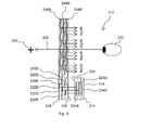
- a projection display 210 for displaying an image to an observer 212 that uses waveguide techniques to generate a display defining a large exit pupil at the point of the observer 212 and a large field of view, whilst using a small image-providing light source device.
- the projection display 210 uses a first plate-like waveguide 214 made of light transmissive material such as glass or plastic and a second plate-like waveguide 216 made from a light transmissive and light transparent material such as glass or plastic.
- the projection display 210 additionally includes an image-providing light source device, not shown, located to inject image bearing light into the first plate-like waveguide 214 through a first face 218.
- the image-providing light source device includes a micro-display arranged to provide information to be displayed to the observer 212. Additionally the image-providing light source device may include a collimating optical arrangement located between the micro-display and the first face 218 of the first plate-like waveguide 214. If used, the collimating optical arrangement is operable to collimate light received from the micro-display and to inject the collimated image bearing light into the first plate-like waveguide 214 through the first face 218.
- Image bearing light produced by the image-providing light source device has a small exit pupil and is fed into the first plate-like waveguide 214, which performs the function of stretching the horizontal pupil of the final display.
- the output from the first plate-like waveguide 214 is fed into the second plate-like waveguide 216, which is arranged to stretch the vertical pupil of the final display and also to act as a combiner for the projection display 210 through which the observer 212 views an outside world scene 220 along a line of sight 222 of the observer 212 through the second plate-like waveguide 216 with information to be displayed to the observer 212 overlaid on the outside world scene 220.
- the image to be displayed to the observer 12 looking through the second plate-like waveguide 216 defines a large exit pupil and a large field of view whilst using a small image generating light source.
- the image bearing light is comprised of three wavelengths, red, green and blue and each of these wavelengths is substantially isolated from one another throughout its passage through the projection display 210 in individual channels as indicated by referenced R, G and B.
- Image bearing light injected into the first plate-like waveguide 214, via first face 218 is incident on one of three first grating 224R, 224G, 224B, each arranged internally within the first plate-like waveguide 214 and substantially parallel with the first face 218 and one each associated with an individual channel R, G, B.
- first gratings 224R, 224G, 224B diffracts therefrom such that the incidence angle of the light on the internal surfaces of channel R, G, B is greater than the critical angle for the material from which the channel R, G, B is formed.
- the image bearing light is constrained within the channel R, G, B to propagate along the first plate-like waveguide 214 reflecting from each internal surface in turn to follow a predefined light path 226R, 226G, 226B.
- the relative field angles of the light incident on the first plate-like waveguide 214 at the first face 218 are preserved within each channel R, G, B and the information required to regenerate the original image is preserved.
- the first gratings 224R, 224G, 224B also serve to radiate the image bearing light out of the first plate-like waveguide 214.
- Each first grating 224 is a low efficiency grating which diffracts a small amount of light out of the first plate-like waveguide 214 on each interaction with incident image bearing light.
- the second plate-like waveguide 216 is located with a first face 228 parallel with a second face 230 of the first plate-like waveguide 214 and is arranged to receive the image bearing light exiting the second face 230 from each channel R, G, B of the first plate-like waveguide 214.
- the second face 230 is parallel to the first face 218 of the first plate-like waveguide 214.
- the first face 228 of the second plate-like waveguide 216 is located adjacent and close to the second face 230 of the first plate-like waveguide 214.
- the second plate-like waveguide 216 includes separate channels R, G, B each having a second grating 232R, 232G, 232B located therein arranged substantially parallel to the first face 228 of the second plate-like waveguide 216 and each second grating 232R, 232G, 232B is operable to diffract impinging image bearing light received from an associated first grating 224R, 224G, 224B of the first plate-like waveguide 214 at an angle that is larger than the critical angle for the material from which the channel R, G, B is formed. Accordingly, received image bearing light will propagate inside one of the channels R, G, B of the second plate-like waveguide 216 to follow the predefined light path 226R, 226G, 226B.
- the image bearing light continues along the light path 226R, 226G, 226B to a third grating 234R, 234G, 234B arranged within each channel R, G, B of the second plate-like waveguide 216 which is arranged to diffract the received image bearing light out of the second plate-like waveguide 216 towards the observer 212.
- Each second grating 232R, 232G, 232B is arranged such that its diffractive power is rotated through 90 degrees to that of the diffractive power of its associated parallel first grating 224R, 224G, 224B to rotate incident image bearing light towards its associated third grating 234R, 234G, 234B.
- Each third grating 234R, 234G, 234B is a low efficiency grating, such that as image bearing light propagates along a light path 226R, 226G, 226B within a channel R, G, B of the second plate-like waveguide 216, each interaction with the third grating 234R, 234G, 234B causes a small proportion of the image bearing light to be diffracted out of the second plate-like waveguide 216. Image bearing light which is not diffracted out of the second plate-like waveguide 216 continues to propagate within its channel R, G, B within the second plate-like waveguide 216.
- a large number of parallel rays of image bearing light exit the second plate-like waveguide 216 via one of the third gratings 234R, 234G, 234B towards the observer 212, which originated at discrete points on the micro-display forming the image generating light source device.
- the correct image to be conveyed to the observer 212 is presented for viewing when the observer 212 views an outside world scene 220 through the second plate-like waveguide 216.
Landscapes
- Physics & Mathematics (AREA)
- General Physics & Mathematics (AREA)
- Optics & Photonics (AREA)
Priority Applications (5)
| Application Number | Priority Date | Filing Date | Title |
|---|---|---|---|
| EP08275084A EP2196729A1 (de) | 2008-12-12 | 2008-12-12 | Verbesserungen an oder im Zusammenhang mit Wellenleitern |
| PCT/GB2009/051676 WO2010067114A1 (en) | 2008-12-12 | 2009-12-09 | Improvements in or relating to waveguides |
| US13/133,278 US8965152B2 (en) | 2008-12-12 | 2009-12-09 | Waveguides |
| ES09768226T ES2721600T5 (es) | 2008-12-12 | 2009-12-09 | Mejoras en o relacionadas con guías de onda |
| EP09768226.4A EP2373924B2 (de) | 2008-12-12 | 2009-12-09 | Verbesserungen an oder im zusammenhang mit wellenleitern |
Applications Claiming Priority (1)
| Application Number | Priority Date | Filing Date | Title |
|---|---|---|---|
| EP08275084A EP2196729A1 (de) | 2008-12-12 | 2008-12-12 | Verbesserungen an oder im Zusammenhang mit Wellenleitern |
Publications (1)
| Publication Number | Publication Date |
|---|---|
| EP2196729A1 true EP2196729A1 (de) | 2010-06-16 |
Family
ID=40688325
Family Applications (1)
| Application Number | Title | Priority Date | Filing Date |
|---|---|---|---|
| EP08275084A Ceased EP2196729A1 (de) | 2008-12-12 | 2008-12-12 | Verbesserungen an oder im Zusammenhang mit Wellenleitern |
Country Status (1)
| Country | Link |
|---|---|
| EP (1) | EP2196729A1 (de) |
Cited By (55)
| Publication number | Priority date | Publication date | Assignee | Title |
|---|---|---|---|---|
| WO2014036537A1 (en) * | 2012-08-31 | 2014-03-06 | Nguyen Ian A | Polarization system for wavelength pass-through in a near-to-eye display |
| GB2529003A (en) * | 2014-08-03 | 2016-02-10 | Wave Optics Ltd | Optical device |
| CN106125308A (zh) * | 2012-04-25 | 2016-11-16 | 罗克韦尔柯林斯公司 | 用于显示图像的装置和方法 |
| US9507149B2 (en) | 2010-10-19 | 2016-11-29 | Bae Systems Plc | Image combiner |
| WO2017139176A1 (en) * | 2016-02-11 | 2017-08-17 | Microsoft Technology Licensing, Llc | Waveguide-based displays with anti-reflective and highly-reflective coating |
| CN107111204A (zh) * | 2014-09-29 | 2017-08-29 | 奇跃公司 | 用于从波导中输出不同波长光的架构和方法 |
| US9772446B2 (en) | 2014-03-14 | 2017-09-26 | Bae Systems Plc | Displays |
| CN107632406A (zh) * | 2016-07-18 | 2018-01-26 | 北京灵犀微光科技有限公司 | 全息波导、增强现实显示系统及显示方法 |
| WO2018096359A3 (en) * | 2016-11-28 | 2018-07-26 | Bae Systems Plc | Multiple waveguide structure for colour displays |
| CN108474879A (zh) * | 2016-01-06 | 2018-08-31 | 伊奎蒂公司 | 具有嵌入式二向色滤光器的双面成像光导 |
| WO2018164914A3 (en) * | 2017-03-07 | 2018-10-11 | Apple Inc. | Head-mounted display system |
| CN108700712A (zh) * | 2016-02-29 | 2018-10-23 | 奇跃公司 | 虚拟和增强现实系统及方法 |
| CN108803027A (zh) * | 2018-03-26 | 2018-11-13 | 成都理想境界科技有限公司 | 一种近眼显示系统 |
| US10247943B1 (en) | 2015-05-18 | 2019-04-02 | Rockwell Collins, Inc. | Head up display (HUD) using a light pipe |
| US10295824B2 (en) | 2017-01-26 | 2019-05-21 | Rockwell Collins, Inc. | Head up display with an angled light pipe |
| CN110036235A (zh) * | 2016-12-06 | 2019-07-19 | 微软技术许可有限责任公司 | 具有用于再循环光的外围侧面几何形状的波导 |
| WO2019143416A1 (en) * | 2018-01-22 | 2019-07-25 | Facebook Technologies, Llc | Systems, apparatuses, and methods for monochromatic display waveguides |
| EP3380878A4 (de) * | 2016-01-06 | 2019-07-31 | Vuzix Corporation | Zweikanaliger bildgebungslichtleiter mit dichroitischen reflektoren |
| CN110100200A (zh) * | 2016-12-22 | 2019-08-06 | 奇跃公司 | 使用二向滤波器在波导中进行颜色分离 |
| US10401620B1 (en) | 2011-09-30 | 2019-09-03 | Rockwell Collins, Inc. | Waveguide combiner system and method with less susceptibility to glare |
| EP3400476A4 (de) * | 2016-01-06 | 2019-09-04 | Vuzix Corporation | Doppelseitiger bildgebungslichtleiter |
| EP3547008A1 (de) * | 2018-03-30 | 2019-10-02 | Coretronic Corporation | Optische wellenleitervorrichtung und anzeige |
| KR20190136078A (ko) * | 2017-04-18 | 2019-12-09 | 매직 립, 인코포레이티드 | 반사 유동성 재료들에 의해 형성된 반사 층들을 갖는 도파관들 |
| US10509241B1 (en) | 2009-09-30 | 2019-12-17 | Rockwell Collins, Inc. | Optical displays |
| CN110651211A (zh) * | 2017-03-21 | 2020-01-03 | 奇跃公司 | 具有用于分体式光瞳的空间光调制器照射的显示系统 |
| WO2020088055A1 (zh) * | 2018-10-31 | 2020-05-07 | 东南大学 | 基于彩色偏振体光栅的全彩波导耦合近眼显示结构、制备方法及ar可穿戴设备 |
| US10698203B1 (en) | 2015-05-18 | 2020-06-30 | Rockwell Collins, Inc. | Turning light pipe for a pupil expansion system and method |
| CN111492273A (zh) * | 2017-12-22 | 2020-08-04 | 迪斯帕列斯有限公司 | 多层波导显示元件 |
| US10732407B1 (en) | 2014-01-10 | 2020-08-04 | Rockwell Collins, Inc. | Near eye head up display system and method with fixed combiner |
| US10746989B2 (en) | 2015-05-18 | 2020-08-18 | Rockwell Collins, Inc. | Micro collimator system and method for a head up display (HUD) |
| US10795160B1 (en) | 2014-09-25 | 2020-10-06 | Rockwell Collins, Inc. | Systems for and methods of using fold gratings for dual axis expansion |
| CN111766707A (zh) * | 2020-07-21 | 2020-10-13 | 谷东科技有限公司 | 二维扩瞳的波导显示装置和增强现实显示装置 |
| CN111902765A (zh) * | 2018-03-28 | 2020-11-06 | 迪斯帕列斯有限公司 | 波导显示元件 |
| US11086125B2 (en) | 2016-05-12 | 2021-08-10 | Magic Leap, Inc. | Distributed light manipulation over imaging waveguide |
| US11300795B1 (en) | 2009-09-30 | 2022-04-12 | Digilens Inc. | Systems for and methods of using fold gratings coordinated with output couplers for dual axis expansion |
| US11307432B2 (en) | 2014-08-08 | 2022-04-19 | Digilens Inc. | Waveguide laser illuminator incorporating a Despeckler |
| US11314084B1 (en) | 2011-09-30 | 2022-04-26 | Rockwell Collins, Inc. | Waveguide combiner system and method with less susceptibility to glare |
| US11320571B2 (en) | 2012-11-16 | 2022-05-03 | Rockwell Collins, Inc. | Transparent waveguide display providing upper and lower fields of view with uniform light extraction |
| US11366316B2 (en) | 2015-05-18 | 2022-06-21 | Rockwell Collins, Inc. | Head up display (HUD) using a light pipe |
| US11448937B2 (en) | 2012-11-16 | 2022-09-20 | Digilens Inc. | Transparent waveguide display for tiling a display having plural optical powers using overlapping and offset FOV tiles |
| EP3903143A4 (de) * | 2018-12-28 | 2022-10-12 | Magic Leap, Inc. | Anzeigesystem mit variabler pixeldichte mit mechanisch betätigtem bildprojektor |
| US11487131B2 (en) | 2011-04-07 | 2022-11-01 | Digilens Inc. | Laser despeckler based on angular diversity |
| US11543594B2 (en) | 2019-02-15 | 2023-01-03 | Digilens Inc. | Methods and apparatuses for providing a holographic waveguide display using integrated gratings |
| US11573356B2 (en) | 2018-03-13 | 2023-02-07 | Interdigital Ce Patent Holdings | Diffraction grating comprising double-materials structures |
| US11586046B2 (en) | 2017-01-05 | 2023-02-21 | Digilens Inc. | Wearable heads up displays |
| US11592614B2 (en) | 2019-08-29 | 2023-02-28 | Digilens Inc. | Evacuated gratings and methods of manufacturing |
| US11604363B2 (en) | 2018-03-13 | 2023-03-14 | Interdigital Ce Patent Holdings | Image sensor comprising a color splitter with two different refractive indexes |
| EP4206121A1 (de) * | 2018-05-04 | 2023-07-05 | Facebook Technologies, LLC | Beugungsgitter für wellenleiter-multiplexing |
| US11703645B2 (en) | 2015-02-12 | 2023-07-18 | Digilens Inc. | Waveguide grating device |
| US11726332B2 (en) | 2009-04-27 | 2023-08-15 | Digilens Inc. | Diffractive projection apparatus |
| US11740472B2 (en) | 2015-01-12 | 2023-08-29 | Digilens Inc. | Environmentally isolated waveguide display |
| US11747568B2 (en) | 2019-06-07 | 2023-09-05 | Digilens Inc. | Waveguides incorporating transmissive and reflective gratings and related methods of manufacturing |
| US11754842B2 (en) | 2015-10-05 | 2023-09-12 | Digilens Inc. | Apparatus for providing waveguide displays with two-dimensional pupil expansion |
| US11972508B2 (en) | 2018-07-02 | 2024-04-30 | Interdigital Ce Patent Holdings, Sas | Image sensor comprising a color splitter with two different refractive indexes, and different height |
| US12099194B2 (en) | 2023-01-11 | 2024-09-24 | Magic Leap, Inc. | Virtual and augmented reality systems and methods |
Citations (3)
| Publication number | Priority date | Publication date | Assignee | Title |
|---|---|---|---|---|
| WO2003081320A1 (en) * | 2002-03-21 | 2003-10-02 | Lumus Ltd. | Light guide optical device |
| EP1731943A1 (de) * | 2004-03-29 | 2006-12-13 | Sony Corporation | Optische einrichtung und virtuelle bildanzeigeeinrichtung |
| WO2007029032A1 (en) | 2005-09-07 | 2007-03-15 | Bae Systems Plc | A projection display with two plate-like, co-planar waveguides including gratings |
-
2008
- 2008-12-12 EP EP08275084A patent/EP2196729A1/de not_active Ceased
Patent Citations (3)
| Publication number | Priority date | Publication date | Assignee | Title |
|---|---|---|---|---|
| WO2003081320A1 (en) * | 2002-03-21 | 2003-10-02 | Lumus Ltd. | Light guide optical device |
| EP1731943A1 (de) * | 2004-03-29 | 2006-12-13 | Sony Corporation | Optische einrichtung und virtuelle bildanzeigeeinrichtung |
| WO2007029032A1 (en) | 2005-09-07 | 2007-03-15 | Bae Systems Plc | A projection display with two plate-like, co-planar waveguides including gratings |
Cited By (111)
| Publication number | Priority date | Publication date | Assignee | Title |
|---|---|---|---|---|
| US11726332B2 (en) | 2009-04-27 | 2023-08-15 | Digilens Inc. | Diffractive projection apparatus |
| US10509241B1 (en) | 2009-09-30 | 2019-12-17 | Rockwell Collins, Inc. | Optical displays |
| US11300795B1 (en) | 2009-09-30 | 2022-04-12 | Digilens Inc. | Systems for and methods of using fold gratings coordinated with output couplers for dual axis expansion |
| US9507149B2 (en) | 2010-10-19 | 2016-11-29 | Bae Systems Plc | Image combiner |
| US11487131B2 (en) | 2011-04-07 | 2022-11-01 | Digilens Inc. | Laser despeckler based on angular diversity |
| US11314084B1 (en) | 2011-09-30 | 2022-04-26 | Rockwell Collins, Inc. | Waveguide combiner system and method with less susceptibility to glare |
| US10401620B1 (en) | 2011-09-30 | 2019-09-03 | Rockwell Collins, Inc. | Waveguide combiner system and method with less susceptibility to glare |
| CN106125308B (zh) * | 2012-04-25 | 2019-10-25 | 罗克韦尔柯林斯公司 | 用于显示图像的装置和方法 |
| CN106125308A (zh) * | 2012-04-25 | 2016-11-16 | 罗克韦尔柯林斯公司 | 用于显示图像的装置和方法 |
| US11460621B2 (en) | 2012-04-25 | 2022-10-04 | Rockwell Collins, Inc. | Holographic wide angle display |
| US10690915B2 (en) | 2012-04-25 | 2020-06-23 | Rockwell Collins, Inc. | Holographic wide angle display |
| WO2014036537A1 (en) * | 2012-08-31 | 2014-03-06 | Nguyen Ian A | Polarization system for wavelength pass-through in a near-to-eye display |
| US8885997B2 (en) | 2012-08-31 | 2014-11-11 | Microsoft Corporation | NED polarization system for wavelength pass-through |
| US11448937B2 (en) | 2012-11-16 | 2022-09-20 | Digilens Inc. | Transparent waveguide display for tiling a display having plural optical powers using overlapping and offset FOV tiles |
| US11320571B2 (en) | 2012-11-16 | 2022-05-03 | Rockwell Collins, Inc. | Transparent waveguide display providing upper and lower fields of view with uniform light extraction |
| US10732407B1 (en) | 2014-01-10 | 2020-08-04 | Rockwell Collins, Inc. | Near eye head up display system and method with fixed combiner |
| US9772446B2 (en) | 2014-03-14 | 2017-09-26 | Bae Systems Plc | Displays |
| CN106575034B (zh) * | 2014-08-03 | 2018-11-23 | 威福光学有限公司 | 出射光瞳扩展的衍射光学波导装置 |
| US10114220B2 (en) | 2014-08-03 | 2018-10-30 | Wave Optics Ltd | Exit pupil expanding diffractive optical waveguiding device |
| GB2529003A (en) * | 2014-08-03 | 2016-02-10 | Wave Optics Ltd | Optical device |
| CN106575034A (zh) * | 2014-08-03 | 2017-04-19 | 威福光学有限公司 | 出射光瞳扩展的衍射光学波导装置 |
| GB2529003B (en) * | 2014-08-03 | 2020-08-26 | Wave Optics Ltd | Optical device |
| US10359635B2 (en) | 2014-08-03 | 2019-07-23 | Wave Optics Ltd. | Exit pupil expanding diffractive optical waveguiding device |
| US11709373B2 (en) | 2014-08-08 | 2023-07-25 | Digilens Inc. | Waveguide laser illuminator incorporating a despeckler |
| US11307432B2 (en) | 2014-08-08 | 2022-04-19 | Digilens Inc. | Waveguide laser illuminator incorporating a Despeckler |
| US10795160B1 (en) | 2014-09-25 | 2020-10-06 | Rockwell Collins, Inc. | Systems for and methods of using fold gratings for dual axis expansion |
| CN107111204A (zh) * | 2014-09-29 | 2017-08-29 | 奇跃公司 | 用于从波导中输出不同波长光的架构和方法 |
| US11042032B2 (en) | 2014-09-29 | 2021-06-22 | Magic Leap, Inc. | Architectures and methods for outputting different wavelength light out of waveguides |
| US11016300B2 (en) | 2014-09-29 | 2021-05-25 | Magic Leap, Inc. | Architectures and methods for outputting different wavelength light out of waveguides |
| CN107111204B (zh) * | 2014-09-29 | 2021-02-09 | 奇跃公司 | 用于从波导中输出不同波长光的架构和方法 |
| US10901219B2 (en) | 2014-09-29 | 2021-01-26 | Magic Leap, Inc. | Architectures and methods for outputting different wavelength light out of waveguides |
| US11796814B2 (en) | 2014-09-29 | 2023-10-24 | Magic Leap, Inc. | Architectures and methods for outputting different wavelength light out of waveguides |
| US11740472B2 (en) | 2015-01-12 | 2023-08-29 | Digilens Inc. | Environmentally isolated waveguide display |
| US11703645B2 (en) | 2015-02-12 | 2023-07-18 | Digilens Inc. | Waveguide grating device |
| US10247943B1 (en) | 2015-05-18 | 2019-04-02 | Rockwell Collins, Inc. | Head up display (HUD) using a light pipe |
| US10746989B2 (en) | 2015-05-18 | 2020-08-18 | Rockwell Collins, Inc. | Micro collimator system and method for a head up display (HUD) |
| US11366316B2 (en) | 2015-05-18 | 2022-06-21 | Rockwell Collins, Inc. | Head up display (HUD) using a light pipe |
| US10698203B1 (en) | 2015-05-18 | 2020-06-30 | Rockwell Collins, Inc. | Turning light pipe for a pupil expansion system and method |
| US11754842B2 (en) | 2015-10-05 | 2023-09-12 | Digilens Inc. | Apparatus for providing waveguide displays with two-dimensional pupil expansion |
| EP3400476A4 (de) * | 2016-01-06 | 2019-09-04 | Vuzix Corporation | Doppelseitiger bildgebungslichtleiter |
| US11275244B2 (en) | 2016-01-06 | 2022-03-15 | Vuzix Corporation | Double-sided imaging light guide |
| US10908360B2 (en) | 2016-01-06 | 2021-02-02 | Vuzix Corporation | Two channel imaging light guide with dichroic reflector |
| EP3400466A4 (de) * | 2016-01-06 | 2019-09-04 | Vuzix Corporation | Doppelseitiger bildgebungslichtleiter mit eingebetteten dichroitischen filtern |
| CN108474879A (zh) * | 2016-01-06 | 2018-08-31 | 伊奎蒂公司 | 具有嵌入式二向色滤光器的双面成像光导 |
| CN108474879B (zh) * | 2016-01-06 | 2020-11-03 | 伊奎蒂公司 | 具有嵌入式二向色滤光器的双面成像光导 |
| US10747001B2 (en) | 2016-01-06 | 2020-08-18 | Vuzix Corporation | Double-sided imaging light guide with embedded dichroic filters |
| EP3380878A4 (de) * | 2016-01-06 | 2019-07-31 | Vuzix Corporation | Zweikanaliger bildgebungslichtleiter mit dichroitischen reflektoren |
| US9891436B2 (en) | 2016-02-11 | 2018-02-13 | Microsoft Technology Licensing, Llc | Waveguide-based displays with anti-reflective and highly-reflective coating |
| WO2017139176A1 (en) * | 2016-02-11 | 2017-08-17 | Microsoft Technology Licensing, Llc | Waveguide-based displays with anti-reflective and highly-reflective coating |
| CN108431640A (zh) * | 2016-02-11 | 2018-08-21 | 微软技术许可有限责任公司 | 具有抗反射和高反射涂层的基于波导的显示器 |
| CN108431640B (zh) * | 2016-02-11 | 2020-08-25 | 微软技术许可有限责任公司 | 具有抗反射和高反射涂层的基于波导的显示器 |
| US10739593B2 (en) | 2016-02-29 | 2020-08-11 | Magic Leap, Inc. | Virtual and augmented reality systems and methods |
| CN108700712B (zh) * | 2016-02-29 | 2020-10-13 | 奇跃公司 | 虚拟和增强现实系统及方法 |
| EP4137874A1 (de) | 2016-02-29 | 2023-02-22 | Magic Leap, Inc. | Systeme und verfahren für virtuelle und erweiterte realitäten |
| US11586043B2 (en) | 2016-02-29 | 2023-02-21 | Magic Leap, Inc. | Virtual and augmented reality systems and methods |
| CN112051674A (zh) * | 2016-02-29 | 2020-12-08 | 奇跃公司 | 虚拟和增强现实系统及方法 |
| CN108700712A (zh) * | 2016-02-29 | 2018-10-23 | 奇跃公司 | 虚拟和增强现实系统及方法 |
| EP3423877A4 (de) * | 2016-02-29 | 2019-03-13 | Magic Leap, Inc. | Systeme und verfahren für virtuelle und erweiterte realitäten |
| IL261138B2 (en) * | 2016-02-29 | 2023-06-01 | Magic Leap Inc | Virtual and augmented reality systems and methods |
| US11086125B2 (en) | 2016-05-12 | 2021-08-10 | Magic Leap, Inc. | Distributed light manipulation over imaging waveguide |
| US11314091B2 (en) | 2016-05-12 | 2022-04-26 | Magic Leap, Inc. | Wavelength multiplexing in waveguides |
| CN107632406A (zh) * | 2016-07-18 | 2018-01-26 | 北京灵犀微光科技有限公司 | 全息波导、增强现实显示系统及显示方法 |
| US10795165B2 (en) | 2016-11-28 | 2020-10-06 | Bae Systems Plc | Multiple waveguide structure for colour displays |
| WO2018096359A3 (en) * | 2016-11-28 | 2018-07-26 | Bae Systems Plc | Multiple waveguide structure for colour displays |
| CN110036235B (zh) * | 2016-12-06 | 2020-11-03 | 微软技术许可有限责任公司 | 具有用于再循环光的外围侧面几何形状的波导 |
| CN110036235A (zh) * | 2016-12-06 | 2019-07-19 | 微软技术许可有限责任公司 | 具有用于再循环光的外围侧面几何形状的波导 |
| CN110100200A (zh) * | 2016-12-22 | 2019-08-06 | 奇跃公司 | 使用二向滤波器在波导中进行颜色分离 |
| US11586046B2 (en) | 2017-01-05 | 2023-02-21 | Digilens Inc. | Wearable heads up displays |
| US10295824B2 (en) | 2017-01-26 | 2019-05-21 | Rockwell Collins, Inc. | Head up display with an angled light pipe |
| US10705337B2 (en) | 2017-01-26 | 2020-07-07 | Rockwell Collins, Inc. | Head up display with an angled light pipe |
| WO2018164914A3 (en) * | 2017-03-07 | 2018-10-11 | Apple Inc. | Head-mounted display system |
| CN110352370A (zh) * | 2017-03-07 | 2019-10-18 | 苹果公司 | 头戴式显示系统 |
| US11822078B2 (en) | 2017-03-07 | 2023-11-21 | Apple Inc. | Head-mounted display system |
| US11467416B2 (en) | 2017-03-21 | 2022-10-11 | Magic Leap, Inc. | Display system with spatial light modulator illumination for divided pupils |
| US11703691B2 (en) | 2017-03-21 | 2023-07-18 | Magic Leap, Inc. | Display system with spatial light modulator illumination for divided pupils |
| CN110651211A (zh) * | 2017-03-21 | 2020-01-03 | 奇跃公司 | 具有用于分体式光瞳的空间光调制器照射的显示系统 |
| US11079603B2 (en) | 2017-03-21 | 2021-08-03 | Magic Leap, Inc. | Display system with spatial light modulator illumination for divided pupils |
| EP3612866A4 (de) * | 2017-04-18 | 2020-12-23 | Magic Leap, Inc. | Wellenleiter mit reflektierenden schichten aus reflektierenden fliessfähigen materialien |
| US11215744B2 (en) | 2017-04-18 | 2022-01-04 | Magic Leap, Inc. | Waveguides having reflective layers formed by reflective flowable materials |
| KR20190136078A (ko) * | 2017-04-18 | 2019-12-09 | 매직 립, 인코포레이티드 | 반사 유동성 재료들에 의해 형성된 반사 층들을 갖는 도파관들 |
| KR20220039834A (ko) * | 2017-04-18 | 2022-03-29 | 매직 립, 인코포레이티드 | 반사 유동성 재료들에 의해 형성된 반사 층들을 갖는 도파관들 |
| CN110753865A (zh) * | 2017-04-18 | 2020-02-04 | 奇跃公司 | 具有由反射可流动材料形成的反射层的波导 |
| CN111492273A (zh) * | 2017-12-22 | 2020-08-04 | 迪斯帕列斯有限公司 | 多层波导显示元件 |
| CN111492273B (zh) * | 2017-12-22 | 2023-08-22 | 迪斯帕列斯有限公司 | 多层波导显示元件 |
| US10942355B2 (en) | 2018-01-22 | 2021-03-09 | Facebook Technologies, Llc | Systems, devices, and methods for tiled multi-monochromatic displays |
| US11675199B1 (en) | 2018-01-22 | 2023-06-13 | Meta Platforms, Inc. | Systems, devices, and methods for tiled multi-monochromatic displays |
| WO2019143416A1 (en) * | 2018-01-22 | 2019-07-25 | Facebook Technologies, Llc | Systems, apparatuses, and methods for monochromatic display waveguides |
| US11112608B2 (en) | 2018-01-22 | 2021-09-07 | Facebook Technologies, Llc | Systems, apparatuses, and methods for image shifting in monochromatic display devices |
| US11112607B2 (en) | 2018-01-22 | 2021-09-07 | Facebook Technologies, Llc | Systems, apparatuses, and methods for monochromatic display waveguides |
| US11231588B1 (en) | 2018-01-22 | 2022-01-25 | Facebook Technologies, Llc | Systems, devices, and methods for tiled multi-monochromatic displays |
| US11493767B1 (en) | 2018-01-22 | 2022-11-08 | Meta Platforms Technologies, Llc | Systems, devices, and methods for tiled multi-monochromatic displays |
| US11573356B2 (en) | 2018-03-13 | 2023-02-07 | Interdigital Ce Patent Holdings | Diffraction grating comprising double-materials structures |
| US11604363B2 (en) | 2018-03-13 | 2023-03-14 | Interdigital Ce Patent Holdings | Image sensor comprising a color splitter with two different refractive indexes |
| CN108803027A (zh) * | 2018-03-26 | 2018-11-13 | 成都理想境界科技有限公司 | 一种近眼显示系统 |
| CN111902765A (zh) * | 2018-03-28 | 2020-11-06 | 迪斯帕列斯有限公司 | 波导显示元件 |
| CN111902765B (zh) * | 2018-03-28 | 2022-05-31 | 迪斯帕列斯有限公司 | 波导显示元件 |
| EP3547008A1 (de) * | 2018-03-30 | 2019-10-02 | Coretronic Corporation | Optische wellenleitervorrichtung und anzeige |
| CN110320588A (zh) * | 2018-03-30 | 2019-10-11 | 中强光电股份有限公司 | 光波导装置及显示器 |
| US10871613B2 (en) | 2018-03-30 | 2020-12-22 | Coretronic Corporation | Optical waveguide apparatus and display |
| EP4206121A1 (de) * | 2018-05-04 | 2023-07-05 | Facebook Technologies, LLC | Beugungsgitter für wellenleiter-multiplexing |
| US11972508B2 (en) | 2018-07-02 | 2024-04-30 | Interdigital Ce Patent Holdings, Sas | Image sensor comprising a color splitter with two different refractive indexes, and different height |
| WO2020088055A1 (zh) * | 2018-10-31 | 2020-05-07 | 东南大学 | 基于彩色偏振体光栅的全彩波导耦合近眼显示结构、制备方法及ar可穿戴设备 |
| US11640063B2 (en) | 2018-12-28 | 2023-05-02 | Magic Leap, Inc. | Variable pixel density display system with mechanically-actuated image projector |
| US12055722B2 (en) | 2018-12-28 | 2024-08-06 | Magic Leap, Inc. | Variable pixel density display system with mechanically-actuated image projector |
| EP3903143A4 (de) * | 2018-12-28 | 2022-10-12 | Magic Leap, Inc. | Anzeigesystem mit variabler pixeldichte mit mechanisch betätigtem bildprojektor |
| US11543594B2 (en) | 2019-02-15 | 2023-01-03 | Digilens Inc. | Methods and apparatuses for providing a holographic waveguide display using integrated gratings |
| US11747568B2 (en) | 2019-06-07 | 2023-09-05 | Digilens Inc. | Waveguides incorporating transmissive and reflective gratings and related methods of manufacturing |
| US11899238B2 (en) | 2019-08-29 | 2024-02-13 | Digilens Inc. | Evacuated gratings and methods of manufacturing |
| US11592614B2 (en) | 2019-08-29 | 2023-02-28 | Digilens Inc. | Evacuated gratings and methods of manufacturing |
| CN111766707A (zh) * | 2020-07-21 | 2020-10-13 | 谷东科技有限公司 | 二维扩瞳的波导显示装置和增强现实显示装置 |
| US12099194B2 (en) | 2023-01-11 | 2024-09-24 | Magic Leap, Inc. | Virtual and augmented reality systems and methods |
Similar Documents
| Publication | Publication Date | Title |
|---|---|---|
| EP2373924B1 (de) | Verbesserungen an oder im zusammenhang mit wellenleitern | |
| EP2196729A1 (de) | Verbesserungen an oder im Zusammenhang mit Wellenleitern | |
| US11815781B2 (en) | Transparent waveguide display | |
| US11927759B2 (en) | Exit pupil expander | |
| CN109656026B (zh) | 一种大视场角的全息光波导显示装置及方法 | |
| CA2844839C (en) | Projection display | |
| AU2017219414B2 (en) | Compact head-mounted display system | |
| US8493662B2 (en) | Waveguides | |
| US9465213B2 (en) | Waveguides | |
| EP2376971B1 (de) | Verbesserungen an oder im zusammenhang mit wellenleitern | |
| EP2269111B1 (de) | Verbesserungen im zusammenhang mit wellenleitern | |
| JP6171740B2 (ja) | 光学デバイス及び画像表示装置 | |
| EP2110701A1 (de) | Verbesserungen an oder im Zusammenhang mit Wellenleitern | |
| US20100246003A1 (en) | projection displays | |
| EP2196843A1 (de) | Verbesserungen an oder im Zusammenhang mit Wellenleitern | |
| EP2163924A1 (de) | Verbesserungen im Zusammenhang mit Wellenleitern | |
| US20210165216A1 (en) | Correction optical member and head-mounted display | |
| CN118140474A (zh) | 双面波导 | |
| EP4094116A1 (de) | Lichtleiter und vorrichtung zur anzeige virtueller bilder | |
| EP2196842A1 (de) | Verbesserungen an oder im Zusammenhang mit Wellenleitern | |
| CN117849932A (zh) | 一种增强现实显示组件及设备 |
Legal Events
| Date | Code | Title | Description |
|---|---|---|---|
| PUAI | Public reference made under article 153(3) epc to a published international application that has entered the european phase |
Free format text: ORIGINAL CODE: 0009012 |
|
| AK | Designated contracting states |
Kind code of ref document: A1 Designated state(s): AT BE BG CH CY CZ DE DK EE ES FI FR GB GR HR HU IE IS IT LI LT LU LV MC MT NL NO PL PT RO SE SI SK TR |
|
| AX | Request for extension of the european patent |
Extension state: AL BA MK RS |
|
| STAA | Information on the status of an ep patent application or granted ep patent |
Free format text: STATUS: THE APPLICATION HAS BEEN REFUSED |
|
| 18R | Application refused |
Effective date: 20100716 |